

Page 1
[MC850C Technical Data] (Specifications are subject to change without prior notice.)
MOUNTING PRECAUTIONS
Accessories
• Schottky diode (for motor)
• Capacitors (for motor)
• Double sided tape
• Silicone flex wire (Red,Black,Blue)
• Heatshrink tube, red (x1), black (x1)
• Miniature screwdriver
(Use to press the pushbutton switch.)
Important:
Because the MC850C has pure race competition specifications, it is
designed so that it is difficult to operate the protection circuits. Use at an
overload may cause trouble. Incorrect power supply polarity or a power
supply or motor short circuit may cause the MC850C to burn out.
Install the receiver and receiver antenna away from the
amp, motor cord, power cord, Nicd battery, and other parts
that carry a high current.
Metal and carbon chassis and other conductive parts
transfer switching noise. When mounting the receiver to
such a chassis, use thick double-sided tape to mount the
receiver as far away from the chassis as possible.
Always install a motor noise suppresser capacitor. Also, do
not forget to service the brushes, and other parts.
If noise causes the receiver to operate erroneously, control may be lost
and an extremely dangerous situation may occur
Insert the connectors firmly.
If vibrations while running cause the connectors to work loose, control
may be lost and an extremely dangerous situation may occur.
Do not run the vehicle in the rain or through puddles or on muddy
or snowy roads.
If moisture enters the amp, erroneous operation may cause loss of
control and an extremely dangerous situation may occur. It may also
cause amp trouble. Should moisture enter and cause erroneous
operation, send the MC850C out for repair and inspection.
Always turn the power switches on and off in the following order:
ON: Transmitter -> receiver (amp switch)
OFF: Receiver (amp switch) -> transmitter
If the power switches are operated in the opposite order, the vehicle
may run unexpectedly and an extremely dangerous situation may
occur.
When going to and returning from the circuit, and when
storing the model, always remove the Nicd battery.
If the switch is turned on erroneously, control may be lost or a fire may
start.
Always perform a check of operation before running.
When making adjustments, remove the motor, or place the
vehicle on a stand, so that it cannot run.
When not set up correctly, the vehicle may run unexpectedly and an
extremely dangerous situation may occur.
MC8
MC850C0C
I
NSTRUCTION
NSTRUCTION
M
ANUAL
ANUAL
1M23N17902
Serial communication function (Options)
The following settings and operations are possible with a Windows PC by using the optional interface unit (CIU-2).
*Windows is registered trademark of Microsoft Corporation.
Before using your MC850C, please read this manual thoroughly
and use the MC850C properly and safely. After reading this
manual, store it in a safe place.
• No part of this manual may be reproduced in any form
without prior permission.
• The contents of this manual are subject to change without
prior notice.
• This manual has been carefully written. Please write to
Futaba if you feel that any corrections or clarifications
should be made.
Thank you for purchasing an MC850C . The MC850C is a high-frequency drive FET speed control developed for model
electric cars. It is compact and light weight competition speed control, and uses a simple digital setting system.
Applicable motors (Number of turns is criteria.)
Use the MC850C with a motor with 5 turns or more.
*If a motor with a number of turns smaller than the above
is used, the heat protector and overcurrent protection
circuit may operate. The number of turns of the motor is
a criteria only. Depending on the running conditions, the
protection circuit may operate even if the condition
above is satisfied.
Power supply
Nicd, NiMH battery 4~7 cells
(4.8~8.4V)
FEATURES
• SMD MOSFETs with smallest internal resistance for
minimal losses and maximum power
• PWM frequency is Performed by load adaptive
•
The upper case made from aluminum
• Heat protector
• Low-voltage protection function
• Power left on alarm function
• External solder points with 12 AWG silicone flex wire
•
Terminal is Oxygen-Free-Copper
•
Serial communication function
INSTALLATION TIPS
• Mount the speed control in the model using the double-sided foam tape supplied.
• Provide plenty of cooling openings in the bodywork; this increases the performance and extends the life of all lectronic
components.
• Install the speed control in a location where it is protected from crash damage.
• The speed control should be installed in such a way that you have easy access to all connectors and the set-up button.
Important:
•Ensure that there is an adequate distance (approx. 3 cm) between the speed control and power cables and the receiver or receiver antenna. Avoid
direct contact between all power system components and the receiver or antenna, as this can cause interference. If you encounter interference
problems, re-position the components in the model.
•The antenna should be run vertically up and away from the receiver. Avoid contact with any parts made of carbon fibre or metal. See also the
instructions supplied with your radio control system.
• Operating system: Forward and brake (resolution:255)
• Power requirement: Nicd, NiMH battery 4~7 cells (4.8~8.4V)
• PWM frequency:
Forward:100Hz〜10kHz/Initial value:2.5kHz〜3.0kHz
Brake:2.0kHz
• BEC voltage: 6.0V (excluding at less than 6V)
• Setting: One-touch input by pushbutton switch.
• Current capacity (FET rating) :
Forward :840A (Momentary load: 3360A)
Brake :240A
• Case size: 28.7x26.2x14.5mm (excluding protruding parts)
• Silicon cord gauge size: AWG12 equivalent
• Weight: 17.5g (excluding connector, cords and switch)
Do not wrap your MC850C in foil.
It is important to provide a free flow of cooling air over it.
Do not remove the case of
MC850C
.
The MC850C may not be repairable.
Never reverse the battery polarity.
Reverse connection will immediately destroy the amp.
Mount the
MC850C
so that conductive parts do not directly touch
the solder parts of the input/output cord.
A short circuit may occur.
If a peddle or other foreign object gets caught in the gears
or the vehicle hits an obstruction, do not try to forcefully run
vehicle.
Forcefully running the vehicle will cause trouble.
Do not touch the motor or MC850C immediately after
running.
Touching the motor or amp immediately after running may result in
serious burns.
If the motor is connected to the speed control, you must not
run the motor by connecting a separate battery.
This will wreck the un
Turn the power switches on in the state where the vehicle is
floated.
When turnning on, depending on the receiver used, a motor may rotate
for a moment. Be careful not to injure a finger etc. by rotation of the
wheels.
MOUNTING PRECAUTIONS
Special Markings
Pay special attention to the
safety at the parts of this
manual that are indicated by
the following marks.
Mark Meaning
Procedures which may lead to a dangerous condition and cause death or serious injury to the user
if not carried out properly.
Procedures which may lead to a dangerous condition or cause death or serious injury to the user if
not carried out properly, or procedures where the probability of superficial injury or physical
damage is high.
Procedures where the possibility of serious injury to the user is small, but there is a danger of
injury, or physical damage, if not carried out properly.
Symbol:
:Prohibited
:Mandatory
• Data logging function data read and erase (Data logging memorizes the running current and power supply voltage for
approximately 8 minutes at 1 second intervals.)
• Variable frequency range setting: 100Hz ~ 10kHz (Sets the load response system variable frequency range.) Dead
band: ±2µs ~ ±55µs (The neutral point range can be set.)
•
Low battery protection voltage setting: 2.5V ~ 6.0V (Sets the voltage which cuts output to motor when the power
supply voltage is drops.)
• Current limiter: 50A ~ 300A, cancel (The current limit for suppressing wasted power can also be set and turned OFF.)
• Brake MAX duty: 0% ~ 100% (Sets the brake strength of the MAX brake point from neutral.)
• Neutral brake: 0% ~ 100% (Brake setting at the throttle neutral point)
Page 2
N
N
N
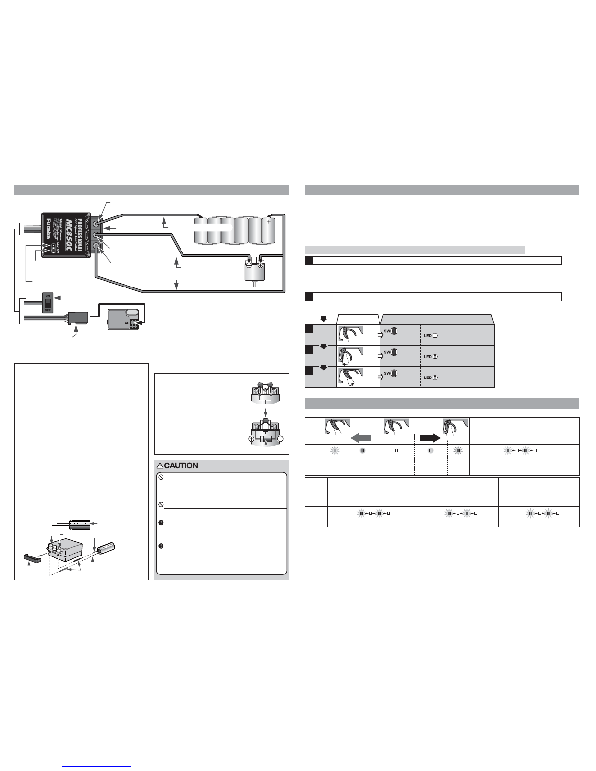
CONNECTION
LED DISPLAY
Negative (-M) motor
Positive (+B) battery
(+M) motor
Receiver connector
Connects to the receiver
throttle channel (CH2).
Power switch
Pushbutton switch
LED
Terminal cover
Negative (-B) battery
Negative terminal mark
POWER CAPACITORS
Power Capacitor stores battery energy and supplies this
to the motor additionally when extra power is required.
[Reference]
The MC850C has excellent acceleration and throttle
follow-up, but use this power capacitor when the course
to be run requires more than maximum power. However,
on a small technical course, not using the power
capacitor may also be effective.
[INSTALLATION]
See the pictures for the example of installation.
1 Remove the terminal cover from the MC850C.
2 Use the included heat shrink tube to isolate the pins of the
Power Capacitor. This will also make it easier to indicate the
polarity of the Power Capacitor. Place the red heat shrink tube
on the positive terminal and the black heat shrink tube on the
negative terminal.
3 The Power Capacitor needs to be soldered to the speed control
between + (positive = M.B.+ ) and - (negative = BAT.-).
4 Attach the terminal cover to the MC850C.
[Wiring Precautions]
• Always set the MC850C power switch to the OFF position before
performing any wiring.
• When stripping the covering of the silicon cord to the length
needed for soldering, be sure not to cut the center conductor with
the cutter or nippers.
• Refer to the diagram above and check the polarity before
performing wiring. (The 3 colors, red, blue, and black, of the
silicon cord indicate the polarity.)
• When soldering to the terminals of the MC850C, remove the
terminal cover. (After soldering, re-install the terminal cover.)
Heat shrink tube
(positive = red / negative = black)
Never reverse the capacitor,schottky diode and wires
polarity.
The capacitor may break or the capacitor electrolyte may leak.
The schottky diode breaks.
Reverse connection will immediately destroy the amp.
Never use solder containing acid flux.
Use solder containing rosin flux only. Do not inhale the solder
vapours. This might damage health.
Vibrationproof the capacitor by mounting it with thick
double sided tape.
If the pin of the capacitor is broken, it may short-circuit with the pin
between + and - terminal of the speed control.
Be careful when soldering to the tags on the speed control;
don’t overheat the tags with your soldering iron and take
great care to avoid short-circuits between two of the three
tags on the speed control.
Such a short-circuit would destroy the speed control.
Silicone flex wire Red
Silicone flex wire Blue
Silicone flex wireBlack
In set-up mode MC850C stores every step when you press the Set-up button. All the settings are stored in the unit even when the
speed control is subsequently disconnected from the battery. Set up the following basic functions on your transmitter (if present):
• High ATV, EPA (throttle travel) - maximum Low ATV, EPA, ATL (brake travel) - maximum
• EXP, EXPO (exponential) - start with 0
• SUB trim (neutral trim) - center TH trim - center
• Throttle reverse (servo reverse) - any setting; must not be changed after completion of set-up procedure.
• Asymmetrical stick travel is possible (2/3 throttle - 1/3 brake)
If your transmitter does not feature these set-up functions, it is already in “basic set-up” mode.
Remove the motor pinion, or ensure in some other way that the wheels of the model are free to rotate.
• Switch the transmitter on.
• Set the transmitter throttle stick to neutral, and then switch the speed control on.
•
Depending on the neutral position of the throttle stick, the red and green LED will blink simultaneously (orange) and a beeping
sound will be repeated. (Alarm: Waiting for neutral data)
Turn on the power in following order.
• The SET LED flashes green, to indicate that the unit is in set-up mode.
• This completes the set-up procedure.
Hold the SET button pressed in for at least 3 seconds using the small screwdriver supplied.
Motors with no suppressor capacitors, or
inadequate suppression, may cause the MC850C
to malfunction. Always solder the capacitors
supplied to your motor.
The schottky diode improves the efficiency of
the speed control / motor combination and
provides extra protection to the brake FETs. The
white ring must always face the positive side.
Schottky diode
Suppressor capacitors
Solder the suppressor capacitors and the
Schottky diode to the motor.
©FUTABA CORPORATION
2007,02 ①
MC850C
Protection Circuits
Heat protection:
After FET overheating is detected, the output to the motor is gradually lowered and when 125 degress is reached, a
protection circuit operation alarm is activated and output to the motor is cut. The protection circuit is automatically reset by a drop in
the FET temperature.
Low battery protection:
When the power supply voltage drops, the output current to the motor is limited and supply voltage to the
receiver is ensured. When the power supply voltage drops to the set voltage (initial setting 3.0V), a protection circuit operation alarm is
activated and output to the motor is cut. The protection circuit is automatically reset by recovery of the power supply voltage.
Terminal
cover
SET button operation LED
Neutral
point
setting
High
point
setting
Brake MAX
point
setting
• Neutral state
The MC850C operating state can be checked with the LED as shown below.
flashes red and the motor beeps.
*Not used with PCM receivers.
*When the transmitter if OFF, this function is not performed
in environments such that the servo operates erroneously
Off
On (green) On (red)
Neutral
point
High
point
Brake MAX
point
Brake Foward
On (red)
*Becomes
brighter nearer
the MAX point.
On (green)
*Becomes
brighter nearer
the high point.
LED
LED
* The confirmation beep sounds only when the motor was connected.
(-;negative)
(+;positive)
(-;negative)
(+;positive)
SET UP
• Full brake
state
• Full high
state
•
Press SET button
once.
•
Press SET button
once.
•
Press SET button
once.
LED goes out and the
motor beeps.
flashes green two times
and the motor beeps.
LED goes out
flashes orange and the motor beeps. flashes orange and the motor beeps.flashes red and the motor beeps.
flashes green three times
and the motor beeps.
LED goes out
* Since the data is read at the end of setting
of all points, the points cannot be set
independently.
* If the amp power was turned off during
setting, the setting points cannot be
memorized. (The previous settings are
retained.)
* The confirmation beep sounds only when
the motor was connected.
* If you make a mistake during the set-up
procedure, an setting is not completed.:
switch MC850C off and start again from
the first step.
* Check the operation by the following "LED
DISPLAY." When throttle operation and
the CHECKER LED DISPLAY are not
correct, set up again from the first step.
(Amp power left on alarm)
When the transmitter power
was turned off first.
*at Neutral Brake:
On (green or red)
*When the switch of speed control is turned ON
ahead of a transmitter.
*When the neutral position of a transmitter
differs from the last setup.
(Alarm when waiting for the data of a
neutral point)
Operation
Cause
(Protection circuit operation)
When a protection circuit operates.
(
Data error alarm
)
Displayed when an abnormal
signal was input.
Transmitter throttle
operation
3
4
5
1
2
FUTABA CORPORATION Makuhari Techno Garden Bldg., B6F 1-3 Nakase, Mihama-ku, Chiba 261-8555, Japan Phone: (043) 296-5119 Facsimile: (043) 296-5124
 Loading...