

Page 1

GYRO QUICK START
1M23N23902
Page 2

INTRODUCTION
The Futaba® GY701 is a heading hold AVCS gyro
and head speed governor in one box. Its cutting-edge
MEMS (Micro Electro Mechanical System) sensor
design, ultra high-speed processing and advanced
PID control algorithm put it a quantum leap ahead
of all other heading hold gyros in size, weight and
performance. The GY701 has been optimized for
model helicopter competition.
Please read through this guide completely before
fl ying the GY701. You must also read the instruction
manual in its entirety (including all of the precautions
and safety warnings). The goal of this quick start
guide is to get you up and fl ying with the GY701 in
a minimum number of steps. It is also recommended
that you fi nd the optimum settings using the gyro
mode only. Once you have found the optimum
settings and are satisfi ed with the fl ight performance,
please refer to the GY701 instruction manual to
begin governor setup. This quick start guide also
assumes that you are familiar with your transmitter
and programming functions.
The information within this manual will provide a
heading hold 3D setup that is mild overall. If you
feel any changes are necessary, please refer to the
GY701 instruction manual.
If you want to setup Normal Mode only (non
heading hold), then please refer to the GY701
Instruction Manual.
2
Page 3
MODEL PREPARATION
Prepare your model by installing the servos, receiver
and power system. Leave the servo arm off of the tail
rotor servo and do not connect the tail rotor servo
to the GY701 until you have completed the setup
later in this guide. Once the correct tail rotor servo
type has been selected, the servo can be connected
to the control box.
GYRO SENSOR INSTALLATION
The gyro sensor should be mounted on a rigid
platform, at least 6 in [152mm] away from a Nitro
Engine. It is not necessary to mount the gyro near the
main shaft of the helicopter, but it is very important
that the mounting area chosen is rigid. Please refer
to your helicopter manufacturer’s instructions for
recommended mounting locations.
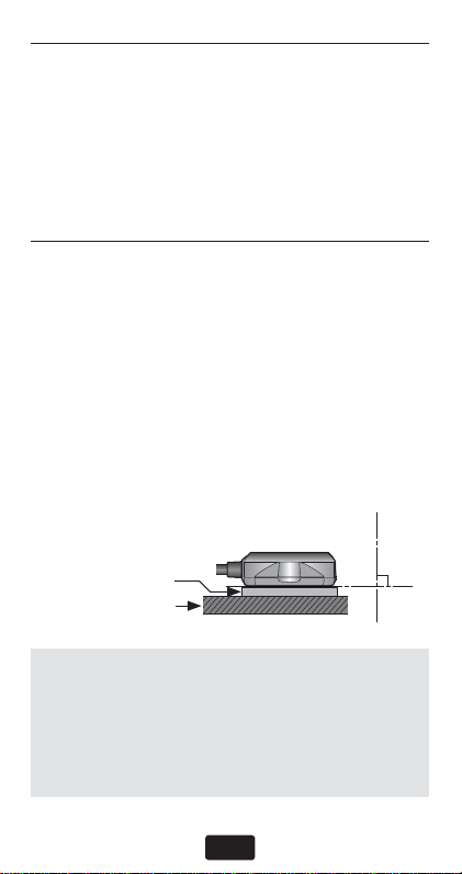
Installing the gyro sensor
When mounting the gyro in a larger electric or .50
through .91 size nitro helicopter, we recommend
using one 2mm Mounting Pad.
Gyro Sensor
2mm Mounting Pad
Gyro Mount
TROUBLESHOOTING
If you experience erratic gyro operation (drifting,
not holding well or inconsistent pirouette rate),
please follow the troubleshooting tips listed below.
1. Always verify that your model’s tail rotor
control and drive system are working correctly.
3
Page 4

GYRO SENSOR INSTALLATION
2. Electromagnetic interference could affect the
gyro or tail rotor servo. Mount the gyro in a
different location, away from the electronic
speed control, servos and drive motor.
3. The trouble may be caused by vibration.
Verify that your helicopter’s components are
balanced. If problems persist, try mounting
the gyro in a different location.
TAIL ROTOR SERVO INSTALLATION & SETUP
Follow your transmitter instructions and program
the transmitter as follows:
❑ Enable the gyro function within the transmitter .
❑ Set the gyro mode to AVCS (GY) within the
transmitter.
❑ Set the remote gyro gain to 70% AVCS in the
transmitter for the Normal and Hold fl ight
conditions. Use 60% AVCS for all idle up
conditions. See “Setting The Gain” section in
the instruction manual for more details.
❑ Set the Tail Rotor ATV/EPA to 100% for both
left and right.
❑ Set D/R to 75% for both left and right. This
will reduce the maximum pirouette rate. Make
adjustments to these values once the initial test
fl ight has been completed.
❑ It is recommended that you run 30%
softening expo on the tail rotor channel
within the transmitter.
WARNING
n
the gyro until the servo type has been selected. Operating
the servo using the incorrect setting may damage the
GY701 or the servo.
Do not connect the tail rotor servo to
l
4
Page 5
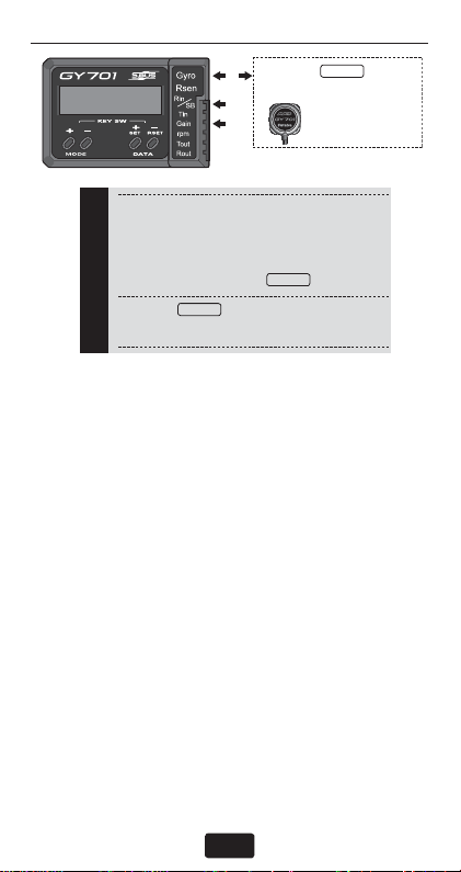
CONTROL BOX INSTALLATION
(1) Gyro:
1
s Connect the gyro sensor.
2
3
(2) Rin/SB:
s S.BUS receiver: Connect to the S.BUS out-
put of the receiver.
s Other than S.BUS receiver: Connect to the
rudder channel output.
Receiver
(3) Gain:
s Connect to the gyro gain channel output.
Gyro
Find a suitable location for the GY701 control box
and mount it using double sided tape. Connect the
gyro sensor to the [Gyro Rsen] connector on the
control box and ensure the clip is fi rmly engaged.
Connect the supplied extensions to the GY701
connecter. Route the wires through the helicopter
mechanics and connect them to the appropriate
receiver channels. If you are using a standard
receiver, then the only two connections needed
are Receiver Tail Rotor Channel ➞ GY701 [Rin]
connection and Receiver Gain Channel ➞ GY701
[Gain] connection. To determine the appropriate
receiver channels, please check your transmitter’s
instruction manual.
If using a Futaba S.Bus receiver, then only one
extension is needed between the S.Bus Receiver
connection and the GY701 [SB] connection. If
any other information is needed please see the
“S.Bus Basic Setting” section of the GY701
Instruction Manual.
Gyro
*Insert the sensor
connector until it is
firmly locked.
Gyro
5
Page 6

CONTROL BOX INSTALLATION
Using wire mounts, wiring fi xtures molded into
the helicopter, or hook and loop material, route the
extensions to the receiver. Ensure that the extensions
leading to the receiver cannot become entangled in
rotating components and make sure the extensions
are not rubbing against metal or carbon fi ber which
may damage the wires. Once the power system is
installed and connected, please move onto the next
step to learn how to program the gyro.
GY701 BASIC SETUP
Turn your transmitter on and allow it to initialize.
Switch the helicopter on and allow the GY701 to
initialize. During the initialization of the gyro, the
screen will show an animated helicopter. Once the
screen changes to show status, the initialization
is complete.
6
Page 7

Push DATA
+/– key
Push MODE
+/– key
MENU STRUCTURE
Max. revolution
Home
screen
Gyro Basic
Governor Basic
S.Bus Basic
Engine runtime
OLED display mode
LED display mode
Operation mode
Gyro Expert
Governor Expert
Push MODE +/– key
for 1 second
From the home screen the mode [+] and [–] button
will take you through the various status screens for
the gyro or governor. It also displays basic options.
7
Page 8

MENU STRUCTURE
From the home screen the data [+] and [–] button
will navigate the upper menus which include the
Home screen, Gyro Basic, Governor Basic and S.Bus
Basic menus. Once the menu you would like to enter
is selected (for example Gyro Basic), simply press
the mode [+] or [–] button to navigate the options.
Once you have found the option you would like
to change simply press the data [+] or [–] button.
Please take a few minutes to become accustomed
to navigating the interface.
To select an Expert menu (for example Gyro Expert
or Governor Expert) simply press either mode [+]
or [–] button and continue to hold for one second.
If you have performed this correctly the screen will
change to either Gyro Expert or Governor Expert.
Feel free to navigate the various menus and change
options since we will be completely resetting the
gyro and governor before beginning setup. Please
review the menu structure listed to become familiar
with the options available.
GY701 SETUP
Once you are done navigating the menus and have
become accustomed to the user interface it is time
to reset the gyro and governor. Cycle the receiver
power and allow the gyro to initialize. Press the data
[+] button until Gyro Basic is shown on the display.
Press and hold the mode [+] button for one second
to enter Gyro Expert Mode. Once the screen shows
Gyro Expert, press the mode [–] button until “Data
Reset?” is shown. Next press the data [+] button and
the display will change to show “Exec.??”. The gyro
is asking you for confi rmation before resetting the
gyro. Press the data [+] button again and the gyro will
8
Page 9

GY701 SETUP
be reset to the defaults and the screen will change to
“Exec.—“ to confi rm that the gyro has been reset.
Cycle the receiver power and allow the gyro to
initialize. T o disable the governor, press the mode [+]
button until “Opr.Mode Gyro+Gov” is shown. Press
the data [+] button until the screen shows “Opr.Mode
Gyro”. This indicates that the gyro only is operating
and the governor has been disabled. Press the mode
[+] button until the home screen is shown again.
Press the data [+] button until “Gyro Basic” is shown.
Press the mode [+] button to scroll through the menu
options until “ServoType” is displayed on the screen.
Press the mode [+] button until the proper servo type
has been selected.
Push MODE
+/– key
Servo type [default: DG:1520]
Selection of the servo type to be used. The
servo type is changed to Digital 1520tDigital
760tAnalog by pushing data [+] or [–] key.
DG 760: BLS251, S9256, S9251
DG 1520: BLS254, BLS257, S9254, S9257
9
Page 10

MENU STRUCTURE
WARNING
The servo type parameter must match the
type of servo you are using. Incorrect setting
may damage the GY701 or the servo, possibly
resulting in a loss of control during flight.
Turn the receiver and transmitter power off for now .
TAIL ROTOR SERVO INSTALLATION
❑ Install the tail rotor servo into the mechanics
and connect the servo to the gyro. Remove the
servo arm screw from the servo. Turn the receiver
power on and allow the gyro to initialize. Enter the
“Gyro Basic Setting” mode and go to parameter
(4) “Servo Limit Point Setting”. While in the
servo limit setting the servo will remain centered.
90°
❑ Place an appropriate servo arm onto the servo
and ensure that it is perpendicular to the tail rotor
pushrod as shown. Remove the unused sides of
the servo arm.
❑ Install the control ball supplied with your
helicopter onto the servo arm. For larger electric
models or nitro powered models we recommend
placing the ball 13.25mm from center. Once the
control ball has been installed, place the arm back
10
Page 11

TAIL ROTOR SERVO INSTALLATION
onto the servo ensuring that it is perpendicular to
the tail rotor pushrod. Install the servo arm screw.
13.25−16.5 mm
(Depending on T/R
linkage geometry)
Carefully hold the tail rotor pushrod ball link
onto the servo arm and verify that the tail rotor
operation matches the transmitter stick input. If
necessary, reverse the operation direction within
your transmitter.
Press the mode [+] key until “GY.Dir Normal”
is shown on the screen. Carefully hold the tail
rotor pushrod ball link onto the servo arm. Rotate
the helicopter counter clockwise (or what would
normally be left tail rotor) and ensure that the gyro
compensates by adding right tail rotor. If the gyro
compensates the incorrect direction, then press the
data [+] or [–] key until the gyro compensates the
correct direction.
Gyro direction [default: Normal]
The gyro compensation direction is changed
by pushing the data + or – key.
11
Page 12

TAIL ROTOR SERVO INSTALLATION
WARNING
Verify that the gyro compensates in the correct direction before flight. If the compensation
direction is incorrect the model will pirouette
uncontrollably, at a very high rate.
Next we need to set the servo limits within the gyro
to ensure the tail rotor servo does not travel too far,
causing binding. While performing this step, simply
hold the tail rotor pushrod link onto the tail rotor
servo ball link to ensure nothing can bind and cause
damage to the servo.
Enter the “Servo Limit” setting menu on the GY701.
From the home screen press the data [+] key until
Gyro Basic is shown on the screen. Now press the
mode [+] key until “Sv.Limit” is shown on the
screen. Move the tail rotor stick slowly towards full
left and full right while listening for servo binding.
Press the data [+] or data [–] key to increase or
decrease the servo travel limit. The goal is to have
maximum throw with no binding or servo buzzing
at the end points.
Limit setting [default: 100%, setting
range: 50 150%]
WARNING
When using the GY701 for the first time, or
when making changes in the throw of a servo,
always perform the limit setting operation.
12
Page 13

SELECTING THE FLIGHT MODE
Press the mode [+] key until “FL T .mode” is displayed
on the screen. It is recommended that you start with
the 3D fl ight mode even for beginners. The 3D mode
offers a higher pirouette rate and better pirouette
consistency. Press the data [+] key until “FLT .mode
3D” is displayed on the screen.
Flight mode [default: F3C]
Selection of the flight style. F3C mode is more
precise rudder control; the 3D mode is more
active rudder control; pirouette speed is faster
than F3C mode. The mode is changed by
pushing the data+ or – key.
Pirouette rate at AFR100% to full stick:
F3C = 450 deg/sec
3D = 720 deg/sec
SETTING THE PIROUETTE RATE
The pirouette rate of the GY701 is controlled by the
gyro rotation rate settings and the transmitter tail
rotor channel endpoints or dual rates. When using
the 3D fl ight mode it is recommended to reduce your
tail rotor channel end points or dual rates within
the transmitter to 75% and then test the pirouette
rate. If the pirouette rate is too slow, then increase
the tail rotor channel end point or dual rates within
the transmitter.
13
Page 14

FINISHING UP
Ensure that all extensions and servo wires are
attached and bundled within the helicopter and that
everything is plugged in correctly. Before the test
fl ight verify all settings and ensure that the gyro
compensates the proper direction.
Ensure that:
❑ the Transmitter and Receiver batteries are fully
charged.
❑ the gyro mounting pads are in good condition.
❑ the gyro wiring has some slack in it and all wires
are clear of the main frame.
❑ the GY701 servo type parameter matches the
servo you are using.
❑ the tail rotor servo arm is perpendicular to the
pushrod and the pitch slider is centered.
❑ the servo does not bind when full left or full right
tail rotor is applied.
❑ the gyro is operating in the correct mode (AVCS
or Normal).
❑ the tail rotor stick operates the tail rotor the correct
direction.
❑ the gyro compensates the correct direction when
the helicopter is rotated.
❑ the gain is set correctly and the gyro operates
in the correct mode (AVCS or Normal) in every
fl ight condition.
14
Page 15

FINISHING UP
WARNING
n
Always make small (1%) adjustments to the
tail rotor D/R or EPA once the value exceeds
100%. Over 100%, it is possible to exceed the
sensor’s Angular Velocity Sensing Range (+/1,200° per second). The gyro will then no longer
control the pirouette rate or consistency. The
pirouette rate can be extremely fast.
If you experiment with the ultra-fast pirouette
rate, make sure that your flight battery and
fuel tank are secure. Also be certain that your
model’s tail rotor drive train is up to the task.
The gain should be raised until the tail begins to
oscillate quickly (also called Tail Wag). Once this
point has been achieved, reduce the gain by a couple
of percent and test fl y the model again. Check and
set the gain for each fl ight mode. T ypically the gain
will be lower for the Idle up 1 and Idle up 2 fl ight
modes due to the higher head speed being used. The
gain for the Hold condition can also be much higher
than other fl ight modes since the head speed is lower
and the engine vibration is minimized.
The Tail Rotor AFR or D/R function within the
transmitter is used to adjust the pirouette rate of the
helicopter. For example at 100% D/R, with the gyro
set to F3C mode, the helicopter will achieve a 450
deg/sec pirouette rate. If you would like the model
to pirouette faster, then increase the AFR or D/R. If
you would like the model to pirouette slower, then
decrease the AFR or D/R.
15
Page 16

FINISHING UP
The tail rotor ratio, tail rotor pitch range and tail
blade length play a large part in achieving optimum
tail rotor performance. The gain value can vary
drastically from model to model and the exact value
should not play a part in the evaluation of the gyro’s
performance. How the gyro operates during fl ight
is the only concern of ours.
16
 Loading...