

Page 1

1M23N04302
AVCS GYRO
GY501
INSTRUCTION MANUAL
YAW-AXIS STABILIZER FOR MODEL HELICOPTER
(RATE GYRO)
Page 2

AVCS GYRO
GY501
INSTRUCTION MANUAL
YAW-AXIS STABILIZER FOR MODEL HELICOPTER
(RATE GYRO)
Page 3

4
Thank you for buying a GY501 AVCS gyro.
Before using your new gyro, please read this manual thoroughly and use the
gyro properly and safely. After reading this manual, store it in a safe place.
FOREWORD
Up to now, movement of the tail from side to side due to changes in the
wind, flight posture, and other disturbances during model helicopter flights
was minimized by increasing the sensitivity of the gyro. However, a bad
effect is that the sensitivity may be increased too much so there was a limit
on how much the tail could be controlled. Changes in F3C rules add
forward and reverse flight aerobatics and demand various flight positions so
that controlling the position of the tail has become more difficult.
The GY501 gyro uses the Futaba AVCS system and makes it possible to
theoretically correct this movement. This increases stabilization of the tail
against disturbances. Since F3C contest fliers who use the GY501 gyro
together with a high response servo, of course, achieve high stability against
wind and other disturbances, it has a large effect also for helicopter novices.
•No part of this manual may be reproduced in any form without prior permission.
•The contents of this manual are subject to change without prior notice.
•This manual has been carefully written. Please write to Futaba if you feel that any
corrections or clarifications should be made.
Page 4

TABLE OF CONTENTS
FOR SAFETY
- Meaning of Special Markings-------------------------------- 6
- Setting Precautions -------------------------------------------- 7
- Operating Precautions----------------------------------------- 8
- Fuselage Maintenance Precautions-------------------------10
BEFORE USE
- Set Contents ---------------------------------------------------11
- Name and Function of Each Part ---------------------------12
- Description of GY501 Operation --------------------------- 13
ASSEMBLY AND ADJUSTMENT
- Connections ---------------------------------------------------29
- Mounting the Gyro Sensor ----------------------------------30
- Use --------------------------------------------------------------31
DATA SETTING
- LCD Display and Edit Keys---------------------------------36
- Function Map--------------------------------------------------37
- Setting of Each Function ------------------------------------38
5
REFERENCE
- Specifications -------------------------------------------------43
- Definition of Abbreviations ---------------------------------44
- GY501 Parameters Sheet ------------------------------------45
- Repair Service-------------------------------------------------46
Page 5

FOR SAFETY
6
FOR SAFETY
To ensure safe use, observe the following precautions.
Meaning of Special Markings
Pay special attention to the safety at the parts of this manual that are
indicated by the following marks.
Mark Meaning
Procedures which may lead to a dangerous
condition and cause death or serious injury to
the user if not carried out properly.
Procedures which may lead to a dangerous
condition or cause death or serious injury to
the user if not carried out properly, or procedures where the probability of superficial
injury or physical damage is high.
Procedures where the possibility of serious
injury to the user is small, but there is a
danger of injury, or physical damage, if not
carried out properly.
Symbol:
; Prohibited ; Mandatory
Page 6

FOR SAFETY
Setting Precautions
Connector Connection
Insert the connectors fully and firmly.
If vibration, etc. causes a connector to work loose during flight, the
heli may crash.
Precautions When Turning on the Power Switch
During initialization, the message **INIT* appears on the GY501
LCD screen.
Do not move the helicopter until this message disappears (in
about 5 seconds).
Also, do not move the transmitter rudder stick from the neutral
position during this period.
7
Sensor Mounting
Always use the attached sensor tape to mount the gyro sensor.
Always reinstall the sensor tape if it has started to separate or tear.
Do not get fuel, waste oil, etc. on the gyro sensor.
The special paint may dissolve.
Page 7

8
FOR SAFETY
At linkage
When the rudder neutral position was changed by the linkage,
the rudder neutral position in the AVCS mode must always be
re-read before use.
Re-reading method:
Turn on the transmitter in the AVCS mode, then turn on the gyro .
Or quickly switch (interval of within 1 second) the remote gain channel
switch between the AVCS mode and Normal mode at least three
times with the transmitter in the ON state. This memorizes the new
rudder position inside the GY501.
Operating Precautions
Avoid sudden temperature changes.
Sudden temperature changes will cause the neutral position to
change. For example, in the winter, do not fly immediately after
removing the model from inside a heated car and in the summer, do
not fly immediately after removing the model from inside an air
conditioned car. Allow the model to stand for about 10 minutes and
turn on the power after the temperature inside the gyro has stabilized.
Also, if the gyro is exposed to direct sunlight or is mounted near the
engine, the temperature may change suddenly. Take suitable measures so that the gyro is not exposed to direct sunlight, etc.
Page 8
FOR SAFETY
Check the remaining receiver and gyro/servo nicd battery
operating time during the adjustment stage and decide how
many flights are remaining.
Never use the transmitter rudder trim in the AVCS mode.
When the rudder is trimmed during flight, the neutral position will
change.
When using the GY501 in the AVCS mode, set revolution mixing
to OFF.
9
Page 9
10
FOR SAFETY
Fuselage Maintenance Precautions
Mounting Precautions
Use a tale rotor drive tube or other part with a high torsion
performance for the tail drive.
Take the strength of the tail into account during inspection and
adjustment.
The amount of improvement of gyro performance has a considerable
effect on the fuselage vibration level or the size, type, linkage
method, looseness, etc. of the tail rotor.
Since a higher gain than usual can be used then the tail rotor is more
effective, the load on the tail is also greater.
Always perform proper maintenance for ultimate performance.
The rigidity of the fuselage tail has a large effect on gyro performance.
Make the fuselage vibration as small as possible.
Fuselage vibration has an adverse affect on gyro operation.
Page 10

BEFORE USE
Set Contents
After unpacking the GY501 set, first check if the following parts are
provided:
GY501 control amp
RATE GYRO
CONNECT
(x1)
BEFORE USE
11
GY501 sensor (x1)
S9205 servo (x1) (Only a set w/servo)
Accessories: Servo horn,
mounting parts
Sensor tape (x3)
Mini screwdriver (x1)
Page 11
12
BEFORE USE
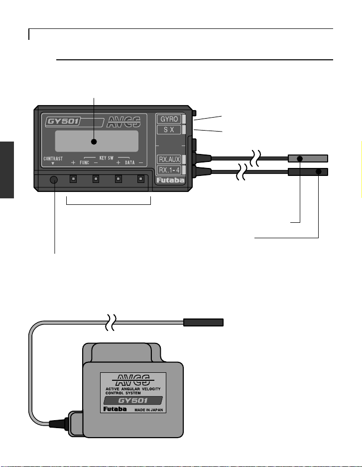
Name and Function of Each Part
GY501 control amp
LCD display
Displays the set data. (8 characters X 1 line)
(Input/output terminals)
RATE GYRO
Gyro sensor input
Rudder servo output
CONNECT
(Receiver connectors)
Edit keys
Used when setting data.
Operated by pushing with the
accessory mini screwdriver.
Remote gain input
Rudder input
LCD contrast trimmer
Allows adjustment of the contrast so that the LCD display is easiest to see.
It is adjusted with the accessory mini screwdriver.
GY501 gyro sensor
To control amp
Stick to the body using the accessory
sensor tape.
Page 12
BEFORE USE
Description of GY501 Operation
The GY501 gyro allows the operator to switch between the AVCS
mode (operation using AVCS function) and Normal mode (conventional gyro mode) from the transmitter. Of course, the GY501 can
also be used in the AVCS mode only.
Remote Gain Function
The remote gain function lets operator perform AVCS mode and
Normal mode sensitivity adjustment and operation mode switching
from the transmitter. The channel used here is called the "remote
gain channel".
(Channel 5 is used.)
13
(Remote Gain Function)
Transmitter
Gain/Mode Selection
• CH5 switch
• Idle-Up switch (T8Usuper)
• Flight condition (T9Z)
Gain Settings
• ATV function
• Gyro mixing (T8Usuper/T9Z)
• Programmable mixing (T9Z)
Receiver
GY501
Mode Settings
• Normal mode (NOR)
• AVCS mode (AVC)
• Selectable mode (CMT)
Gain Settings
• Gyro Gain Adjustment
Remote Gain Channel (CH5)
Page 13
14
BEFORE USE
When Using a T9Z World Champion Model Transmitter
Gyro Sense Mixing
The Gyro Sense Mixing (GYR) function lets operator perform two-point gain
adjustment at each condition. Set the sensitivity at all conditions.
[GY501 Settings]
Select the gyro operation mode at the GY501 Mode screen. (AVC, NOR, or
CMT)
[Transmitter Settings]
ATV function:
Adjust both the RATE A and RATE B rates to 100% at the transmitter ATV
function setup screen.
Gyro Sense Mixing function:
1. Select the Dual Mode (DUO) at the transmitter Gyro Sense Mixing setup
screen.
2. Set the GAIN1 and GAIN2 gains.
(The following page shows a setting example in the CMT mode.)
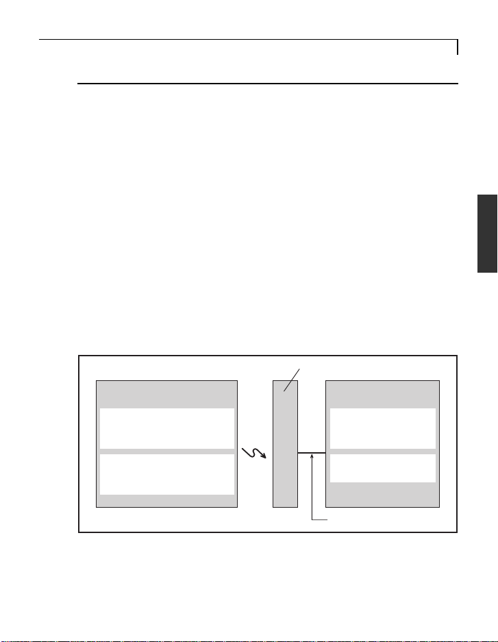
[Sensitivity Display]
The gain display indicates the actual gain at the GY501 G:1 and G:2 screen.
The following shows the relationship between transmitter and gyro setting
when GY501 sensitivity setting is 100% in both the G1 and G2 gain modes.
- Relationship between transmitter and gyro setting
Transmitter
settings
GY501mode
settings
Actual gain
GAIN1
GAIN2
NOR
AVC
CMT
0% - 50% - 100%
Normal mode
AVCS mode
Normal mode AVCS mode
(G2) (G1)
100% - 0% - 100%
Page 14
BEFORE USE
(Setting Example)
Adjust the gyro gain at the Gyro Sense Mixing setup screen at each
condition.
The following shows a setting example in the CMT mode.
Select the Dual Mode (DUO).
GYRO SENCE
DUAL : MODE
85 %
15 %
Use the following values as the sensitivity setting standard:
01 . MODEL-01. NORML HEL PCM 0: 23: 17
: GAIN 1
: GAIN 2
0 20 40 60 80 100
END
Sensitivity rate
Choose the GAIN1 or GAIN2 by the CH5 switch.
15
CH5 switch
Hovering Flight
GAIN1
setting
GAIN2
setting
Actual gain
85%
15%
70% 40%
70%
30%
AVCS side
Normal side
The GY501 sensitivity is 0% at 50%. When set over 50%, the GY501
operates in the AVCS mode and when set under 50%, the GY501
operates in the Normal mode. When setting is changed 1%, the gyro
sensitivity is changed 2%.
Page 15

16
BEFORE USE
When Using a T9Z Transmitter Programmable Mixing
The Programmable Mixing (PMX) function lets operator perform a gain
adjustment at each condition. Set the sensitivity at all conditions.
[GY501 Settings]
Select the gyro operation mode at the GY501 Mode screen. (AVC, NOR, or
CMT)
[Transmitter Settings]
Function Control:
Set the CH5 (GYR) switch to “NUL” at the transmitter Function Control
(FNC) setup screen.
ATV function:
Adjust both the RATE A and RATE B rates to 120% at the transmitter ATV
function setup screen.
Programmable Mixing function:
1. Select the “ACTIVE” mode (ACT) at the transmitter Programmable Mixing
setup screen.
2. Set the mixing type to “OFS”.
3.Set the slave channel to “GYR”.
4. Set the sensitivity rate (RATE).
(The following page shows a setting example in the CMT mode.)
[Sensitivity Display]
The gain display indicates the actual gain at the GY501 G:1 and G:2 screen.
The following shows the relationship between transmitter and gyro setting
when GY501 sensitivity setting is 100% in both the G1 and G2 gain modes.
- Relationship between transmitter and gyro setting
Transmitter
settings
GY501mode
settings
NOR
AVC
CMT
Actual gain
-100% - 0% - +100%
Normal mode
AVCS mode
Normal mode AVCS mode
(G2) (G1)
100% - 0% - 100%
Page 16

BEFORE USE
(Setting Example)
Adjust the gyro gain at the Programmable Mixing setup screen at each
condition. The following shows a setting example in the CMT mode.
Select the “ACTIVE”.
PROG MIX 1
ACTIVE : MODE ( ON) TRIM:
GYR
OFS
LIN
OFS
01 . MODEL-01. NORML HEL PCM 0: 23: 17
*** : MASTER
: SLAVE
: MIX TYPE
MSTR MIX MODE:
HOV CRV CTL
******
******
SWT
NXT
END
17
Select the “GYR”.
PROG MIX 1
Select the “OFS”.
01 . MODEL-01. NORML HEL PCM 0: 23: 17
: RATE+ 70 %
0 20 40 60 80 100
END
Sensitivity rate
Use the following values as the sensitivity setting standard:
Hovering Flight
AVCS mode
Normal mode
Actual gain
+70%
-70%
70% 40%
+40%
-40%
When set over 0%, the GY501 operates in the AVCS mode and when
set under 0%, the GY501 operates in the Normal mode.
Page 17

18
BEFORE USE
When Using a T8Usuper Transmitter
The Gyro Mixing (GYRO) function lets operator perform a gain adjustment at
each Idle-Up switch position.
[GY501 Settings]
Select the gyro operation mode at the GY501 Mode screen. (AVC, NOR, or
CMT)
[Transmitter Settings]
Gyro Mixing function:
1. Select the “ON” mode at the transmitter Gyro Mixing (GYRO) setup
screen.
2. Select the Idle-Up switch for the sensitivity selection.
3. Set the “NORM”, “IDL1” and “IDL2” gains.
(The following page shows a setting example in the CMT mode.)
[Sensitivity Display]
The gain display indicates the actual gain at the GY501 G:1 and G:2 screen.
The following shows the relationship between transmitter and gyro setting
when GY501 sensitivity setting is 100% in both the G1 and G2 gain modes.
- Relationship between transmitter and gyro setting
Transmitter
settings
GY501mode
settings
NORM
IDL1
IDL2
NOR
AVC
CMT
Actual gain
0% - 50% - 100%
Normal mode
AVCS mode
Normal mode AVCS mode
(G2) (G1)
100% - 0% - 100%
Page 18

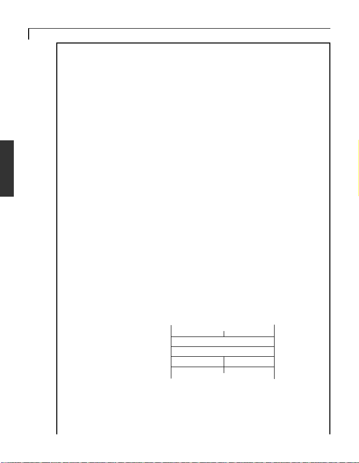
BEFORE USE
(Setting Example)
Adjust the gyro gain at each the Idle-Up swtch position at the Gyro Mixing
setup screen. The following shows a setting example in the CMT mode.
Select the “ON”
mode.
Select the Idle-Up
switch.
19
Switch position
Sensitivity rate
Set the “NORM”, “IDL1” and “IDL2” gains at each setup screen.
Use the following values as the sensitivity setting standard:
(NORM)(IDL1)(IDL2)
AVCS mode
Normal mode
Actual gain
Hovering
85%
15%
70% 40%
Flight
70%
30%
When set over 50%, the GY501 operates in the AVCS mode and when
set under 50%, the GY501 operates in the Normal mode.
Page 19

20
BEFORE USE
When Using a Transmitter ATV Function
The ATV function lets operator perform a gain adjustment at each CH5
switch position.
[GY501 Settings]
Select the gyro operation mode at the GY501 Mode screen. (AVC, NOR,
or CMT)
[Transmitter Settings]
ATV function:
Set the ATV rates at the transmitter CH5 ATV function.
[Sensitivity Display]
The gain display indicates the actual gain at the GY501 G:1 and G:2
screen.
The following shows the relationship between transmitter and gyro setting
when GY501 sensitivity setting is 100% in both the G1 and G2 gain
modes.
- Relationship between transmitter and gyro setting
CH5 Switch CH5 Switch
Transmitter
settings
GY501mode
settings
ATV rates
NOR
AVC
CMT
Forward side Front side
90% - 0% - 90%
Normal mode Normal mode
AVCS mode AVCS mode
Normal mode AVCS mode
(G2) (G1)
Actual gain
100% - 0% - 100%
Page 20

BEFORE USE
When Using a GY501 Gyro Gain Adjustment Function
[Transmitter Settings]
Adjust both the ATV rates to 90% at the transmitter Ch5 ATV function.
[GY501 Settings]
Operation Mode Setting function:
Select the gyro operation mode at the GY501 Mode screen. (AVC, NOR, or
CMT)
Gyro Gain Adjustment function:
Set the G:1 and G:2 gains at the GY501 G:x screen.
- Relationship between transmitter and gyro setting
CH5 Switch CH5 Switch
Transmitter
settings
ATV rates
Forward side Front side
90% (Fixed) 90% (Fixed)
21
GY501mode
settings
NOR
AVC
CMT
Actual gain
Normal mode Normal mode
AVCS mode AVCS mode
Normal mode AVCS mode
(G2) (G1)
100% - 0% - 100%
Page 21

22
BEFORE USE
Initialization
When the power switch is turned on, the GY501 automatically
obtains the reference signal for AVCS function correction and
initializes itself.
Precautions When Turning on the Power Switch
During initialization, the message **INIT* appears on the GY501
LCD screen.
Do not move the helicopter until this message disappears (in
about 5 seconds).
Also, do not move the transmitter rudder stick from the neutral
position during this period.
Page 22

BEFORE USE
AVCS Mode Rudder Trim Reset Function
When the GY501 is used in the AVCS mode only, the AVCS
function automatically detects the rudder neutral position and rudder
trim is essentially unnecessary. However, when the GY501 is used
in the Normal mode, the neutral position is set by conventional
rudder trimming.
In the AVCS mode, the rudder stick position when the power was
turned on is memorized as the neutral position and when the rudder
is trimmed during flight, the neutral position will change.
In the normal mode, when the rudder neutral position was reset, and
the GY501 was switched to the AVCS mode in this state, the neutral
position will change. To correct the difference in the neutral position
in the Normal mode and the AVCS mode, the GY501 reads the
rudder signal at the point at which it was switched from the Normal
mode to the AVCS mode as the neutral reference point. Therefore,
when switching the GY501 from the Normal mode to the AVCS
mode, the following precautions are necessary:
[At power ON]
- When the power was turned on in the Normal mode, the rudder
neutral position already memorized in the GY501 is used.
- When the power was turned on in the AVCS mode, the rudder
signal at that point is memorized and updated.
23
[During use]
- When using the GY501 in the AVCS mode, set revolution mixing
to OFF.
- When the rudder was re-trimmed in the Normal mode and the new
trim position also affects the AVC mode, the rudder trim neutral
position must be memorized in the GY501. In this case, quickly
switch (interval of within 1 second) the transmitter remote gain
switch between the Normal and AVCS sides at least three times at
Page 23

24
BEFORE USE
the neutral trim position set in the Normal mode. This memorizes the
new rudder neutral position in the GY501. When the transmitter has
a function that allows trim setting for each flight condition, such as
the T9Z, the AVCS mode trim position is fixed and this operation is
unnecessary.
Note: The rudder neutral position is memorized inside the GY501.
When the rudder neutral position was changed by the linkage, the
rudder neutral position in the AVCS mode must always be re-read
before use.
Re-reading method
Turn on the transmitter in the AVCS mode, then turn on the gyro .
Or quickly switch (interval of within 1 second) the remote gain
channel switch between the AVCS mode and Normal mode at least
three times with the transmitter in the ON state. This memorizes the
new rudder position inside the GY501.
Page 24

BEFORE USE
Differences Between AVCS Gyro and Conventional Gyro
Compared to a convention gyro, the AVCS gyro has a substantially
improved tail control capacity. Gyro operation also differs from that
of conventional systems in a number of ways.
The following sequentially describes the conventional gyro and the
AVCS gyro.
Conventional gyro
The conventional gyro detects movement of the helicopter's tail and
controls the rudder servo so that movement of the tail stops.
Now, consider hovering when the helicopter is exposed to a side
wind, the tail drifts. When the tail drifts, the gyro detects the tail
rotation angular velocity and operates the servo in the direction that
stops the tail from moving. Drifting of the tail is stopped by control
from the gyro. When the tail stops drifting, the control amount from
the gyro becomes zero. Since the helicopter is always exposed to
side wind, even in this state, the tail starts to drift again. When the
tail drifts, the gyro tries to stop it again. The "drifting stop" operation
is repeated and the tail continues to drift in the wind direction in this
manner. The higher the gyro sensitivity, the smaller the amount of
this drift. However, if the sensitivity is high, hunting will occur and,
therefore, the sensitivity amp has a limit.
25
• Drifting stop
Side wind
Forward
Page 25

26
BEFORE USE
AVCS gyro
This following describes how the AVCS system works when the
helicopter is exposed to a side wind while hovering, the same as the
preceding item. When the helicopter is exposed to a side wind, the
tail begins to drift. The gyro controls the servo so that the movement
of the tail stops, the same as a conventional gyro. At the same time, a
sensor is controlled so that the tail is rotated in the opposite direction
(returns to the original position). In short, the conventional gyro
performs an operation known as "drifting stop", but the AVCS
system performs an operation that "stops drifting and returns to
original position". The "return to original position" operation added
to the AVCS system improves rudder trim operation. In other words,
the gyro can automatically trim the rudder against side winds. This
also applies to reverse flight. When a helicopter is flying in the
forward and reverse directions, the rudder trim is changed to advance, but with the AVCS system, this trim change is performed
automatically and instantaneously so that the tail remains extremely
stable even during high-speed reverse flight.
The AVCS system requires a high-precision angular velocity sensor.
The GY501 realizes a high-precision angular velocity detection
function and extremely small output drift by using a new type of
gyro sensor. This minimizes rudder neutral position drift during
flight and eliminates the need to trim the rudder during flight.
• The tail remains extremely stable.
Side wind
Forward
Page 26

BEFORE USE
Differences in rudder control method
The following describes the differences between conventional gyro
and AVCS gyro rudder control.
The conventional gyro sends the rudder control signals from the
transmitter to the rudder servo and starts to move the tail. When the
tail moves, the gyro detects this movement and generates a signal to
stop it. If the tail continues to move even in this state, a rudder
control signal larger than the signal from the gyro must be applied
from the transmitter. That is, the difference between the rudder
control signal from the transmitter and the control signal that attempts to stop this from the gyro becomes the actual amount of
movement of the tail. Ordinarily, the rudder control signal is amplified several times over by the gyro amp and is balanced with the
gyro control signal so that the transmitter can be used at the normal
steering angle.
The AVCS system uses a different rudder control method. As
described in the preceding section, it has additional functions that
"attempt to return movement by external force to the original
position" and that generate an angular velocity proportional to the
rudder control signal. That is, it functionally controls the speed of
rotation of the tail. The original AVCS (Angular Vector Control
System) came from this. In the AVCS mode, when the transmitter
rudder stick is moved when the helicopter was stopped, the rudder
servo controls operation until the tail reaches the specified rotational
speed. Trim deviation of the rudder control signal also becomes a
signal that causes the tail to turn so that even a little trim deviation
causes the tail to move. Therefore, the rudder trim is made the same
in all flight states and must match the neutral reference signal at the
gyro. The method of reading the rudder neutral signal at the gyro
will be described separately. Since the rudder mixing signals from
the transmitter also become a tail rotation signal, all the rudder
mixing functions must be disabled.
27
Page 27

28
BEFORE USE
In the AVCS mode, the gyro automatically trims the rudder so that
linkage changes cannot be verified. Initially, the GY501 trims the
rudder by flying in the Normal mode to take the rudder linkage
neutral position. This centers the linkage. At this time, this rudder
neutral reference point is read to the GY501.
Giving the gyro the rudder neutral reference signal and performing
tail operation by referring to this signal in the AVCS mode in this
way is how the AVCS system differs from the conventional system.
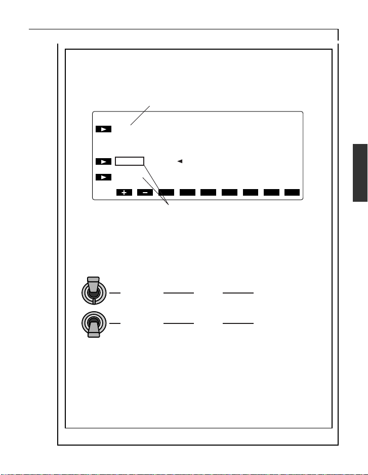
Page 28

ASSEMBLY AND ADJUSTMENT
CONNECT
RATE GYRO
ASSEMBLY AND ADJUSTMENT
Connections
Gyro Sensor (“GYRO”)
Rudder Servo (“SX”)
29
Rudder Channel
(“RX.1-4”)
Connector Connection
Insert the connectors fully and firmly.
If vibration, etc. causes a connector to work loose during flight, the
heli may crash.
Remote Gain Input
(“RX.AUX”)
Connect to receiver
sensitivity setting channel
(normally ch5).
Page 29

30
ASSEMBLY AND ADJUSTMENT
Mounting the Gyro Sensor
The gyro sensor is extremely sensitive to vibrations. Always use the
attached sensor tape to mount the gyro sensor. Stick the sensor tape
to the center of bottom of the sensor and firmly stick the sensor to a
flat part of the helicopter frame so that it does not touch the frame.
Mount the sensor so that the bottom of the sensor is level with the
rotating surface of the tail.
Gyro Sensor
Sensor Tape
Flat part
Always use the attached sensor tape to mount the gyro sensor.
Always reinstall the sensor tape if it has started to separate or tear.
Do not get fuel, waste oil, etc. on the gyro sensor.
The special paint may dissolve.
Page 30

ASSEMBLY AND ADJUSTMENT
Use
The following describes basic use of the GY501. Note that in the
AVCS mode, operation is somewhat different than that of a conventional gyro.
Initial setting
1) Set the gyro operating direction at the GDir screen.
(See page 39 for setting
method)
2) Set the servo operation limit range at the Lmtx screen.
(See page 42 for setting
method)
- Adjust the servo travel so that it is within the linkage range.
3) Set the gyro operation mode at the Mode screen.
(See page 42 for setting
method)
- To use the GY501 in the Normal mode only, set to "Nor". To use the
GY501 in the AVCS mode only, set to "AVC". When switching
between the AVCS mode and Normal mode, set to "CMT".
- When using the GY501 in the "CMT" mode, the AVCS and Normal
mode sensitivities must be set while hovering and during flight.
Therefore, a transmitter (T9Z, T8UHsuper, etc.) with a gyro mixing
function is necessary.
31
The following shows how to use the GY501 in the CMT mode.
4) Adjust the gyro gain.
(See page 39 for setting
method)
- The GY501 initial sensitivity is 100% for both the G1 and G2 gains.
Page 31

32
ASSEMBLY AND ADJUSTMENT
When using a T9Z transmitter, set the sensitivity at the transmitter
without changing the 100% reference value. Use the following
values as the sensitivity setting standard:
- Call the T9Z GYR setup screen.
- Adjust the sensitivity when hovering to 85% at the AVCS side and
15% at the normal side.
- Set the sensitivity during flight to 70% and 30% in the AVCS and
normal modes, respectively.
- At this time, 70% is displayed on the GY501 sensitivity display when
hovering and 40% is displayed on the GY501 sensitivity display
during flight.
*1: The GY501 sensitivity becomes 0% at 50%. When set over 50%,
the GY501 operates in the AVCS mode and when set under 50%, the
GY501 operates in the Normal mode. When setting is changed 1%,
the gyro sensitivity is changed 2%.
When using a transmitter that does not have a gyro sensitivity
switching function, connect the sensitivity setting connector to a
vacant channel and display the GY501 sensitivity setup screen and
set the G1 and G2 gains.
Sensitivity can also be fine adjusted using the transmitter ATV
function.
5) Check the transmitter settings in the AVCS mode.
- Set all the rudder mixing functions to INH.
- Set the hovering and flight rudder trimmers to the same position.
- Make the rudder ATV 100% at all conditions.
- Set the T9Z condition delay function to INH.
Page 32

ASSEMBLY AND ADJUSTMENT
Flight Adjustments
1) Turn on the transmitter power, then turn on the receiver power.
- Never move the model or rudder stick during the 5 seconds the
"INIT" display blinks.
2) Hover in the Normal mode and adjust the rudder neutral position.
- In the AVCS mode, the rudder neutral position is automatically set,
and linkage changes cannot be verified. First, perform rudder neutral
adjustment in the Normal mode.
- Move the transmitter trim lever and reset the neutral position. When
the rudder servo neutral position has changed considerably, readjust
the linkage.
3) When the transmitter rudder trim was adjusted, the rudder neutral
data must be read to the GY501. Therefore, always perform the
following operations:
- Switch the transmitter sensitivity switch quickly (internal of within 1
second) between AVCS and Normal at least three times. "****" is
displayed on the LCD screen to show that data is being memorized.
During this operation, never move the transmitter rudder stick from the
neutral position for at least 1 second immediately after switching the
switch in the state in which the model is on the ground. Memorization
and updating is executed only when the sensitivity switch is in the
AVCS mode position.
33
4) Set the sensitivity to the position at which hunting does not occur
during hovering and flight.
- In the AVCS mode, when the sensitivity is lower than the suitable
sensitivity, operation that resembles conventional hunting or operation that seems to be the opposite of operation of a conventional gyro,
such as a slight drifting of the tail when the sensitivity is high may
occur. Therefore, use a method that finds the suitable value by
checking neutral suppression and pirouette stopping by raising and
lowering the sensitivity.
Page 33

34
ASSEMBLY AND ADJUSTMENT
5) Adjust the hovering and flight rudder effect using the transmitter's
D/R or AFR function.
- Do not adjust with the ATV function. If the ATV function is used,
trimming may change.
(If necessary)
6) When you sense a difference in the rudder effect between the
AVCS and Normal modes, adjust using the GY501 rudder control
linkage.
(See page 40 for setting
method)
- Adjustment method
When the rudder effect in the AVCS is different from the rudder effect
in the Normal mode after adjustment was performed using the
transmitter's D/R or AFR function, adjust the difference using the
NCGx parameter.
7) Adjust the left and right pirouette stopping state by control delay
and tracking.
(See page 40 for setting
method)
(See page 41 for setting
method)
Page 34

ASSEMBLY AND ADJUSTMENT
- Adjustment using the delay function of the T9Z transmitter is also
possible. Since the gyro gain also has a large effect on the stopping
state, make this adjustment after adjusting the sensitivity.
8) When you want to use rudder mixing in the Normal mode, set the
transmitter so that rudder mixing is applied only during Normal
mode operation. Never use rudder mixing in the AVCS mode.
35
Page 35

DATA SETTING
C
36
DATA SETTING
LCD Display and Edit Keys
LCD display
Set data display and operation
status monitoring are possible.
RATE GYRO
Edit keys
Setup screen call
The setup screens can be sequentially called with the FUNC+ or
FUNC- key. For the order in which
the setup screens are called, see the
function map.
Data setting
Perform data setting with the DATA+
or DATA- key. When setting a value,
the data is increased when the
DATA+ key is pressed and is
decreased when the DATA- key is
pressed. The mode can also be
selected using either the DATA+ or
the DATA- key.
Low Battery Alarm
When the power supply voltage drops to 3.8V, "LOW Batt" is
displayed. When this message is displayed, quickly stop operation
and charge the Nicd battery.
Page 36

Function Map
FUNC
”-” key
DATA SETTING
37
Power ON
Initial screen at power on
(P38)
Power supply voltage display
(P38)
FUNC ”+” key
Gyro Gain Adjustment
(P39)
Gyro Reverse
(P39)
Rudder Control Gain
(P40)
Control Delay
(P40)
Gain Tracking
(P41)
Servo Frame Rate
(P41)
Operation Mode Setting
(P42)
Linkage Limit Setting
(P40)
Page 37

38
DATA SETTING
Setting of Each Function
Initial screen at power on
This is the initial screen at power on. When the transmitter power is
off, "*IDLE**" is displayed until the transmitter power is turned on.
After the transmitter power is turned on, "*INIT***" blinks for about
5 seconds to read the reference data. During this period, do not move
the transmitter rudder stick or the helicopter. If the transmitter rudder
stick or helicopter is moved by mistake, the rudder neutral position
will change.
Operation screen display / Power supply voltage display
Normal mode operation
Low battery alarm
Rudder neutral memorization updating
AVCS mode operation
Rudder neutral deviation display
Page 38

DATA SETTING
Displays the receiver power supply voltage.When the voltage drops
to 3.8V, "LOW BAT" is displayed. In the AVCS mode, "A" is
displayed. When the rudder neutral full reset operation was performed, the "****" mark, which indicates execution, is displayed. In
the AVCS mode, when there is a difference between the transmitter
rudder neutral position and the GY501 neutral data, the " " mark is
displayed.
Gyro Gain Adjustment
Initial value: 100%
Performs gyro sensitivity adjustment. Two-point gain adjustment is
possible. The setting range is 0 to 100%. When "A: or "N" is
displayed in accordance with operation mode setting, the GY501
operates in the AVC mode and Normal mode, respectively. The gain
display indicates the actual gain, and changes with transmitter
remote gain adjustment.
39
Gyro Reverse
Sets the direction of operation of the gyro.
Initial value: NOR
Page 39

40
DATA SETTING
Rudder Control Gain
Initial value: ACG:100%, NCG:100%
Sets the rudder stick operation gain. The gain can be set independently for the AVCS mode and Normal mode. When the operation
mode is AVCS, "ACGX" is displayed. In the Normal mode,
"NCGX" is displayed. The display is automatically changed to "A"
or "B" depending on the direction of the rudder stick. The gain of the
set direction can be set. This setting is used in tracking the rudder
operation sensitivity between the AVCS and Normal modes. The
setting range is 30% to 200%.
Control Delay
Initial value: 0%
Sets the rudder stick operation delay. The delay amount can be set
independently for left and right operation of the rudder stick. Adjust
by checking the left and right directions pirouette stopping state. For
instance, when pirouette stopping resembles hunting, increase the
CDI of that direction. On the other hand, to stop drifting, decrease
CDI. The setting range is 0 to 100%.
Page 40

DATA SETTING
Gain Tracking
Initial value: +0%
Adjusts left and right tail stopping. It is used at 0% as standard, but
use this adjustment when pirouette stopping cannot be adjusted using
the CDI parameter. For example, when pirouette stopping resembles
hunting, or right turn pirouette stopping drifts, shift Trk in the +
direction. In the reverse case, shift Trk in the - direction.
If Trk is large, a left and right pirouette speed difference will be
produced. Therefore, adjust gain tracking with the smallest possible
value. The setting range is -20% to +20%.
Servo Frame Rate
Initial value: NOR
Sets the servo output frame rate. The transmitter frame rate (Nor) or
1/2 the transmitter frame rate (High) can be set. Normally, use at
"Nor".
41
Page 41

42
DATA SETTING
Operation Mode Setting
Initial value: CMT
Sets the gyro operation mode. In the "NOR" mode, both G1 and G2
operate in the Normal mode. In the "AVC" mode, both G1 and G2
operate in the AVCS mode. In the "CMT" mode, G1 operates in the
AVCS mode and G2 operates in the Normal mode. In the "Nor"
mode, the GY501 operates the same as conventional gyros. In the
"AVC" mode, the GY501 always operates in the AVCS mode. In the
"CMT" mode, the GY501 can be used in both the AVCS and Normal
modes.
Linkage Limit Setting
Initial value: 100%
Sets the rudder servo travel limit. The linkage limit can be adjusted
by pressing the + and - keys so that the rudder stick is operated and
the servo operates up to the maximum linkage position. When
setting, rudder ATV automatically becomes 200% and the servo
deflection becomes large so that limit setting can be easily performed. A or B is displayed depending on the right or left direction.
Page 42

REFERENCE
Specifications
* Specifications are subject to change without prior notice.
GY501 Ratings
Yaw-axis stabilizer for helicopter (rate gyro)
Display device: 8-character dot matrix liquid crystal display
Operating voltage range: DC 3.8V to 6.0V
Current drain: 60mA (@4.8V, including sensor)
Operating temperature range: -10 to +50 degree C
Operating humidity range: 10 to 90%RH (no condensation)
Dimensions: 56.5 x 30.5 x 16mm (body)
Weight: 34g (body) + 55g (sensor)
S9205 Ratings
Speed: 0.11sec/60degree (@4.8V)
REFERENCE
43
Torque: 5.5kg-cm (@4.8V)
Dimensions: 40.5 x 20 x 37.5mm
Weight: 53g
Page 43

44
REFERENCE
Definition of Abbreviations
The following defines the abbreviations and symbols used in this
manual in alphabetical order. The function names are given on the
description pages.
A
ACGA/B Rudder control gain
(AVCS) p40
AFR AFR function.
ATV ATV function. Steering angle
adjustment function.
AVC AVCS mode.
AVCS AVCS system. AVCS mode.
C
CD1A/B Control delay. p40
CMT Normal/AVC switching mode.
D
D/R Dual rate function.
DUO T9Z dual gain control mode.
F
Frm Servo frame rate. p41
G
G:1A/N Gyro gain 1 side. p39
G:2A/N Gyro gain 2 side. p39
GDir Gyro reverse. p39
GYRO T9Z gyro sense mixing.
H
High High side (frame rate 1/2
side).
I
IDLE Transmitter power OFF state.
p38
INH Use inhibited state.
INIT Initialize. Initialization. p38
L
LCD Liquid crystal display screen.
LmtA/B Linkage limit setting. p42
LOW BAT Low battery error
display. p38
M
Mode Operation mode setting. p42
N
NCGA/B Rudder control gain
(Normal) p40
NOR Normal mode. Normal side.
P
PMIX Programmable mixing.
R
REV Reverse side.
T
Trk Tracking. p41
Page 44

REFERENCE
GY501 Parameters Sheet
* Copy and use.
Helicopter:
Date:
Parameter value value Remarks
G:xx
Gyro Gain Adjustment
Initial Set
G:1 100% 0-100%
G:2 100% 0-100%
45
GDir
Gyro Reverse
ACGx,NCGx
Rudder Control Gain
CD1x
Control Delay
Trk
Gain Tracking
Frm
Servo Frame Rate
Mode
Operation Mode Setting
Lmtx
Linkage Limit Setting
NOR NOR/REV
ACGA 100% 30-200%
ACGB 100% 30-200%
NCGA 100% 30-200%
NCGB 100% 30-200%
CD1A 0% 0-100%
CD1B 0% 0-100%
+0% -20-+20%
NOR NOR/High
CMT CMT/NOR/AVC
LmtA 100%
LmtB 100%
Page 45

46
REFERENCE
Repair Service
Before requesting repair, read this instruction manual again and
recheck your system. Should the problem continue, request repair
service as follows:
Describe the problem in as much detail as possible and send it with a
detailed packing list together with the parts that require service.
• Symptom (Including when the problem occurred)
• System(Transmitter, Receiver, Servo's and model numbers)
• Model (Model name)
• Model Numbers and Quantity
• Your Name, Address, and Telephone Number.
• Dated Proof of Purchase (For Warranty Claims)
Please read the warranty card supplied with your system.
When requesting warranty, please send the card along with some
type of dated proof of purchase.
If you have any questions regarding this product, please consult your
local hobby dealer or contact the Futaba Service Center. The address
and telephone number are listed below. (For U.S.A.) (Telephone
inquiries are accepted from 8:30 AM to 5:00 PM PST daily, except
on Saturday, Sunday and Holidays.)
Address(For U.S.A.)
Futaba Corp. of America
4 Studebaker
Irvine, CA 92618 (949) 455-9888
Makuhari Techno Garden Bldg., B6F 1-3 Nakase, Mihama-ku, Chiba 261-8555, Japan
FUTABA CORPORATION
Phone: (043) 296-5118 Facsimile: (043) 296-5124
©FUTABA CORPORATION 1998, 8
 Loading...