

Page 1

GOVERNOR FOR MODEL HELICOPTER
GV-1
INSTRUCTION MANUAL
33
3
33
Page 2

Thank you for purchasing a Futaba GV-1 governor.
To ensure safe use, please read this manual thoroughly before
using your new governor. After reading this manual, store it in a
safe place.
FOREWORD
The GV-1 is an engine governor for model helicopters.
The governor automatically maintains constant rotor R.P.M.due
to load changes (reaction to torque) by suppressing variations in
the engine speed. The GV-1 works very well in all maneuvers,
from hovering to flying.
-Engine speed can be set from both the GV-1 and the transmitter.
-A magnetic sensing system reads the engine speed.
-Fuel mixture control can be set.
-An LCD panel displays the engine speed and set data.
-No part of this manual may be reproduced in any form without prior permission.
-The contents of this manual are subject to change without prior notice.
-This manual has been carefully written. Please contact Futaba if you feel that any corrections or clarifications should be made to the contents of this manual.
-Futaba is not responsible for the results of use of this product by the customer.
44
4
44
Page 3

TABLE OF CONTENTS
PRECAUTIONS 6
Definition of symbols 6
Setting precautions 7
Operating precautions 9
BEFORE USE 10
Set contents 10
Nomenclature 11
Overview of GV-1 operation 12
Examples 14
ASSEMBLY & ADJUSTMENT 16
Mounting the magnet and sensor 16
GV-1 connections 21
Fuselage setting precautions 22
FUNCTIONS 24
LCD display and edit keys 24
Low battery alarm 24
Function map 25
Initial setting for governor operation 26
Description of functions 33
REFERENCE 47
Specifications 47
Glossary 48
GV-1 PARAMETERS SHEET 49
REPAIR SERVICE 50
55
5
55
Page 4
PRECAUTIONS
To ensure safe use, please observe the following precautions.
Definition of symbols
Pay close attention to the parts of this manual indicated by the following sym-
PRECAUTIONS
bols.
Symbol
Graphic symbols
; Operations that must not be performed.
; Operations that always must be performed.
Meaning
Indicates a procedure that could result
in serious injury or death to the user or
other persons if ignored and not performed properly.
Indicates a procedure that could result
in death or serious injury to the user or
other persons, as well as physical
damage, if ignored and not performed
properly.
Indicates a procedure that may result
in serious injury to the user or other
persons, or physical damage only, if ignored and not performed properly.
66
6
66
Page 5
Setting precautions
When using the GV-1 for the first time, or when making
changes in the throw of a servo, always perform the limit
setting operation.
(Setting method: Page 45)
Always set battery fail safe function at the GV-1.
(Setting method: Page 44)
Since the GV-1, when used, controls the throttle, the battery fail safe function
that is in a PCM transmitter will not be used.
Because the GV-1 controls the throttle, the throttle channel
fail safe function normally set in a PCM transmitter will not
be used. Set the fail safe function as described below.
Transmitter setting
Use the fail safe function for the channel that turns the governor on and
off to set the fail safe position to the point at which the governor is
turned off. With this setting, when the system enters the fail safe state,
the governor will be turned off and the receiver throttle signal will be
output directly.
PRECAUTIONS
77
7
77
Page 6
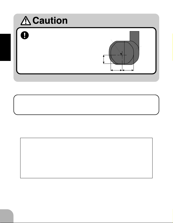
The center of the sensor is
2.2
mm
3.7mm 3.7mm
Center of sensor
is offset.
Sensor
case
different from the center of
the sensor case so be careful
when mounting the sensor.
(Setting method: Page 16)
PRECAUTIONS
When using the PCM1024Z transmitter
When using the condition hold (CHD) function, always set the
throttle servo maximum operating point (MAX THR) to 20% or
less.
Depending on the conditions, this setting will turn on the governor and
prevent the engine from exceeding the set speed even when condition
hold is set.
(Governor ON conditions)
The following conditions must be performed, to turn on the
governor:
-Governor ON/OFF switch set to ON position.
-Throttle stick set to 20% or more from slow position.
-Engine speed raised to 70% or more of set speed.
88
8
88
Page 7
Operating precautions
At the beginning of flight, keep the governor in the OFF
state by setting the throttle stick to no more than 20% from
the slow side.
While the engine is running, turn on the governor at the point which the throttle
stick is at least 20% from the slow side and the engine speed exceeds 70% of
the set speed.
When the model is on the ground, lower the pitch to the
position at which the model does not try to lift off. Do not
take your eyes off the model.
When the governor operates and the rotor speed increases the lift also increases causing the model to try lift off , depending on the pitch position.
Periodically check the sensor output.
(Check method: Page 46)
The magnet rotates at high speed and is subjected to a large centrifugal force.
Check the sensor output and mounting state about once every 10 flights.
If the model begins to shake during operation, immediately
turn off the governor.
(See "Governor on/off operation mode setting" on page
29.)
PRECAUTIONS
When engine speed is not stable at high R.P.M.'s
The carburetor design, etc. may cause the engine to operate
unstable. If this occurs, lower the maximum speed setting to the
range over which there is no problem.
99
9
99
Page 8
BEFORE USE
Set contents
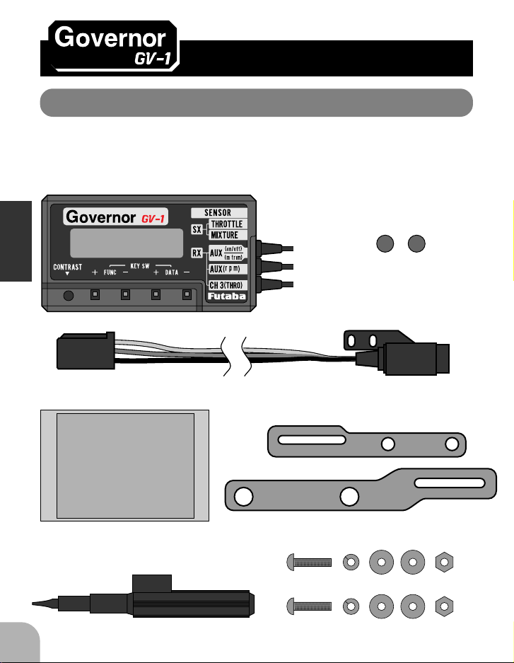
Immediately upon opening the carton, check if the following items are supplied.
GV-1 control amp
Magnet
BEFORE USE
GV-1 magnetic sensor
1010
10
1010
Seal
SENSOR
& Sx
Tx
GV-1
THRO MXTR
SENS.
r.p.m 1 r.p.m 2 r.p.m 3
m.trim GOV on GOV off
on / off
r.p.m THRO
m.trim
Miniature screwdriver
Sensor mounting stay
For 30 engine
For 60 engine
Sensor mounting screws
Page 9
SENSOR
THRO MXTR
r.p.m 1 r.p.m 2 r.p.m 3
m.trim GOV on GOV off
on / off
Tx
GV-1
& Sx
SENS.
r.p.m THRO
m.trim
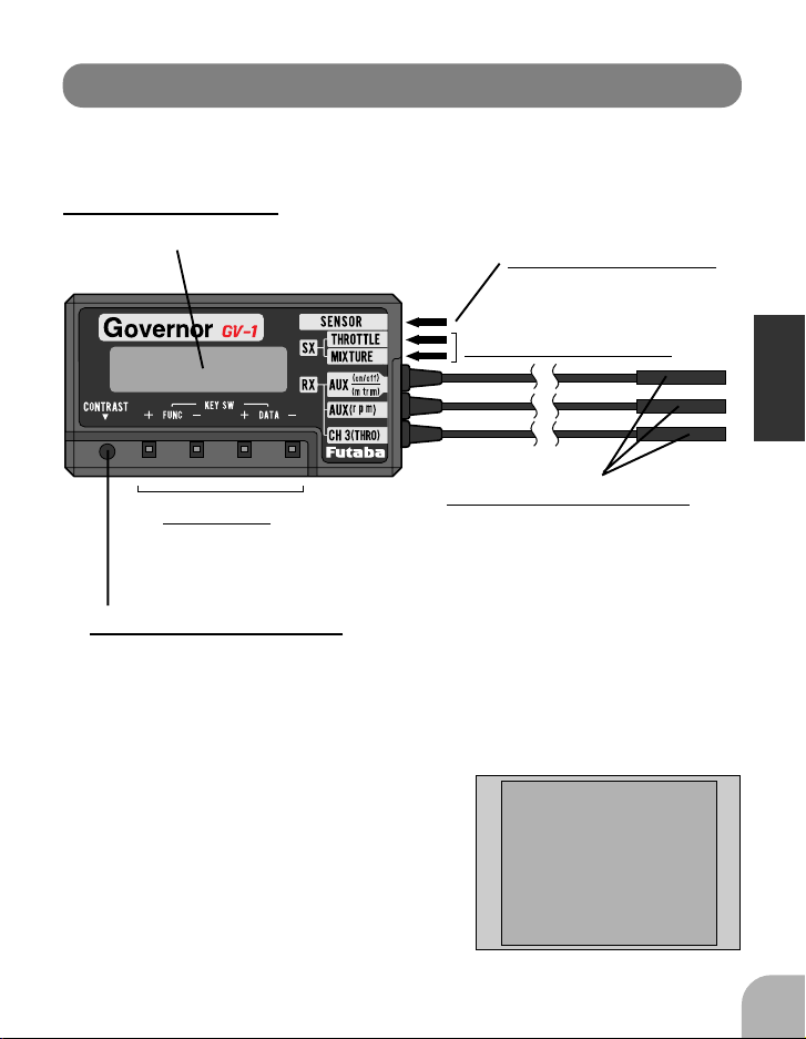
Nomenclature
Control amp
LCD display panel
Displays the speed and set data.
Sensor connector
Servo connectors
Edit keys
Receiver connectors
Used to set data. Press with the accessory miniature
screwdriver.
LCD contrast trimmer
The display contrast can be adjusted so that the LCD display is easy to
read. Adjust the contrast with the accessory miniature screwdriver.
Seal
Stick this seal to the sensor and servo connectors, transmitter switch, etc.
BEFORE USE
1111
11
1111
Page 10
Overview of GV-1 operation
The GV-1 operates from 1000 to 2100rpm main rotor speed . However, the
engine must be running at the set speed. The GV-1 turns off the governor
when the engine is starting or idling.
*Governor operation = Operation that stabilizes the engine speed at the set speed.
When governor turned on and off by switch (Normal
condition)
Setting the switch to the ON position turns on the governor. The following
describes this operation.
-Throttle stick set at least 20% from slow position and engine running at 70% or more of set
BEFORE USE
Governor can be turned
on and off by a switch.
When governor turned on and off by transmitter
throttle stick
The data is set so that the governor can be turned on and off with the transmitter throttle stick. The following describes this operation.
100%
15% or less
(OFF region)
(OFF at slow side)
0%
speed ->->-> ON
-Throttle stick set to maximum slow position ->>-> Remains ON
-Switch set to off position ->->-> OFF
-Throttle stick set at least 20% from slow side
and engine running at 70% or more of set
speed ->->-> ON
-Throttle stick held at 15% or more from slow
side ->->-> Remains ON
-Throttle stick lowered 15% or more from slow
side ->->-> OFF
(Governor operating point)
1212
12
1212
Set speed
20% or more of stick deflection
and 70% of set speed
Page 11
For safe operation, do not turn on the governor under the conditions
shown below. If satisfied while the governor is on, the following conditions will forcibly turn the governor off.
When the governor is off, the transmitter throttle stick controls the
throttle servo.
-Engine started while governor switch in ON position.
-Engine speed is 70% or less of set speed and throttle stick is set to
20% or less from slow side after engine started (governor starting
only).
-Speed set to 999rpm or less (OFF setting).
-Stick signal is lower than stop position setting.
-Engine stopped, or sensor signal abnormal.
-Throttle stick set 15% or less from slow side (only when function
that turns governor on and off by stick is set).
The following operations do not indicate trouble:
(When engine speed rises above the set speed)
A near-vertical dive may cause the engine speed to rise above the
set speed.
(Throttle operation speed and ON/OFF point)
If throttle operation exceeds 70% of the set speed and the rotor
speed rises to the set value, the ON/OFF point may seem to differ
with the operating speed. Delay operation to smoothen the switching operation causes this and does not mean that the ON/OFF point
has changed.
BEFORE USE
(Deviation from set speed)
The GV-1 stabilizes the engine speed to within +1% of the set
speed. For example, if the rotor R.P.M. is set to1500rpm, the Rotor
R.P.M. speed will deviate about +15rpm. However, this poses no
problem from the standpoint of practical use.
1313
13
1313
Page 12
1
2
3
F
N
F
F
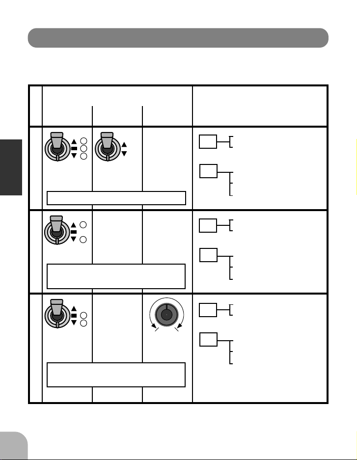
Examples
The GV-1 functions can be selected to match the transmitter used.
Select the functions by referring to the examples shown below.
Speed
switching
Three
positions
CH7(example)
Example 1
BEFORE USE
When used with PCM1024Z
Two positions
CH7(example)
When used with FF8 or PCM1024Z
Example 2
Two positions
CH7(example)
Example 3
When used with FF8 or PCM1024Z
Function
Governor
on/off
OF
O
ON/OFF
CH8(example)
Speed
1
switching
OF
position 1
3
used
(without mixture function)
Speed
OF
switching
2
position 1
3
used
control used
(with mixture function)
Mixture
function
None
None
Mixture
Connection
Sx
Rx
Sx
Rx
Sx
Rx
Throttle servo
Not connected
2P switch channel
3P switch channel
Throttle channel
Throttle servo
Not connected
Not connected
3P switch channel
Throttle channel
Throttle servo
Mixture servo
Volume channel
3P switch channel
Throttle channel
1414
14
1414
Page 13
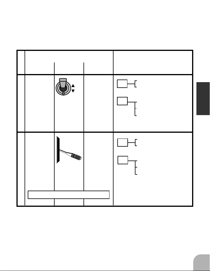
F
N
Speed
switching
Function
Governor
ON/OFF
Mixture
function
Connection
None None
Speed set at
governor side.
OF
O
on/off
Example 4
None None
Speed set at
governor side.
ON/OFF
Throttle stick
Example 5
When there is no vacant channel
Sx
Rx
Sx
Rx
Throttle servo
Not connected
2P switch channel
Not connected
Throttle channel
Throttle servo
Not connected
BEFORE USE
Not connected
Not connected
Throttle channel
1515
15
1515
Page 14
ASSEMBLY & ADJUSTMENT
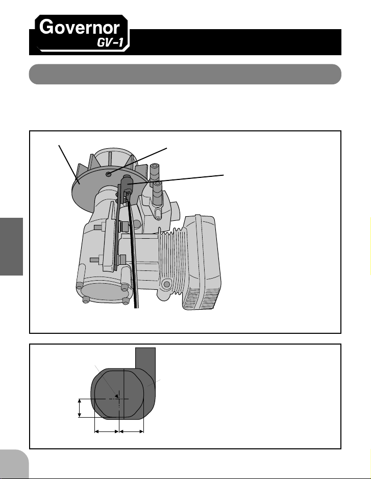
Mounting the magnet and sensor
Modify the cooling fan and install the accessory magnet and attach the magnetic sensor to the engine at the position shown below.
Cooling fan
ASSEMBLY & ADJUSTMENT
Magnet and sensor mounting
Offset the sensor
center position.
2.2
mm
3.7mm 3.7mm
Magnet (Embedded in cooling fan.)
Sensor (Attached to engine
flange through a stay.)
When installing the sensor
magnet to the muffler side,
also refer to the needle side
mounting.
Sensor case
Align the sensor center position and the
center of the magnet shown in the figure
at the left.
Sensor center position
1616
16
1616
Page 15
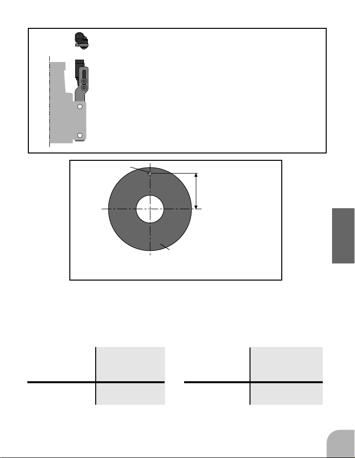
The sensor and stay mounting directions depend on the
sensor mounting position.
Direction of mounting the
sensor to the stay.
Magnet
Distance from center
of engine shaft
Cooling fan
Magnet mounting position
Magnet mounting method
The tables below show the magnet mounting position (example) for each engine.
60 engine
Mounting
position
Distance from
center of
engine shaft
Mounting
position
30 engine
Distance from
center of
engine shaft
Needle side Needle side
With a Kyosho 60 helicopter, do not use a stay. Mount the sensor directly to the
helicopter frame.
27.1-28.8mm
22.0-24.0mm
ASSEMBLY & ADJUSTMENT
1717
17
1717
Page 16
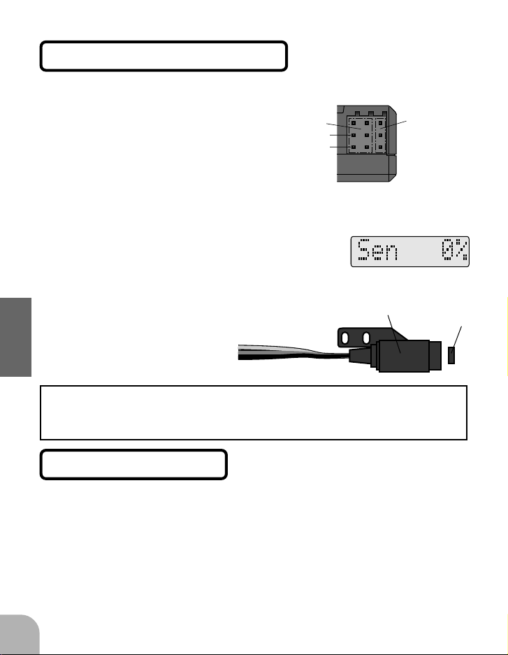
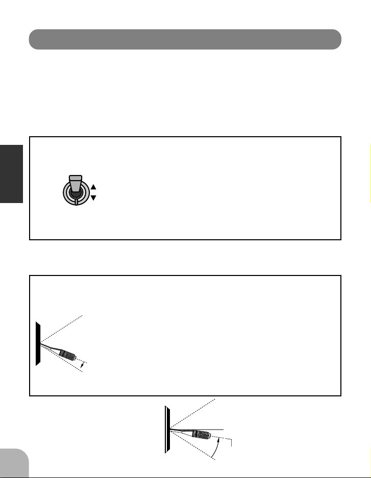
Magnet direction check
(Magnet operating side check)
1Connect the sensor to
the control amp.
Servo
connectors
+
-
2Connect a battery di-
rectly to one of the servo
connectors.
When a battery is connected to the servo
connectors, the control amp is activated.
(Control amp)
3Press the FUNC+ or FUNC- key
until the "sensor percentage"
screen is displayed
4Bring the magnet near the end
of the sensor and check the operating side.
ASSEMBLY & ADJUSTMENT
This is the side at which the displayed value increases. Install the magnet
with this side facing the sensor. Mark this side of the magnet with a felt tip
pen.
Sensor mounting
The sensor mounting method depends on the helicopter and engine.
Sensor
Sensor
connectors
Magnet
1818
18
1818
1Mount the sensor to the sensor stay. (Temporary
assembly)
2Drill a hole in the fan cover at the part correspond-
ing to the sensor so that the distance between the
sensor and magnet can be made 1 to 2mm.
Page 17
3Tighten the sensor stay together with the engine
mounting flange. (Temporary assembly)
4Select the mounting method so that the sensor
does not touch the frame, or other parts of the helicopter. Temporarily mount the sensor and select
the magnet mounting position.
-Install the sensor to the sensor stay using the accessory screws and washers.
-Tighten the sensor stay together with the engine using the engine mount
screw.
Magnet mounting
(Cooling fan modification)
1Drill a hole in the fan at the magnet mounting posi-
tion.
Make the hole about 4.1mm in diameter and 1.5 to 1.7mm deep.
2Embed the magnet in this hole in the direction in
which an output is obtained.
Use epoxy adhesive that cures in 30 minutes or longer.
Do not use epoxies that contain metal such as JB Weld.
Magnet
Cement the magnet to the cooling fan
so that the magnet is level with this side
of the cooling fan.
If the cooling fan is unbalanced and vibrates, etc., balance it by mounting
the spare magnet to the opposite side of the cooling fan in the opposite
polarity (so that it does not output a signal).
ASSEMBLY & ADJUSTMENT
1919
19
1919
Page 18
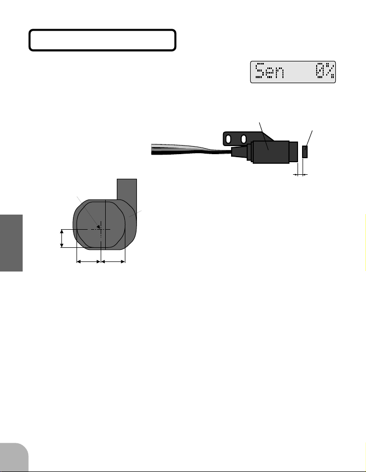
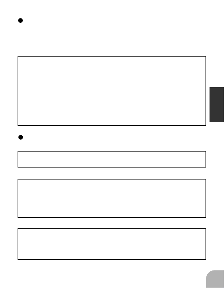
Sensor adjustment
1Call the "sensor percentage"
screen.
2Adjust the sensor position to ob-
tain a sensor output of at least
60%.
Sensor
Magnet
Center of sensor
is offset.
2.2
mm
3.7mm 3.7mm
ASSEMBLY & ADJUSTMENT
3Complete assembly of the sensor by securely
tightening the screws that were temporarily tightened.
4Recheck the sensor output.
2020
20
2020
Sensor
case
1-2mm
Align the sensor center position and
the center of the magnet shown in the
figure at the left.
Page 19

GV-1 connections
Magnetic sensor
Control amp
Throttle servo
Mixture servo
Connected only when
fuel mixture function
used.
Throttle
channel
Speed setting channel
Connected when speed set from
transmitter
Governor ON/OFF / Mixture trim channel
Connected when the governor is turned on and off
from transmitter and when mixture trim function is
used, or when mixture curve data sent from transmitter to governor
Receiver
ASSEMBLY & ADJUSTMENT
2121
21
2121
Page 20

Fuselage setting precautions
Throttle servo linkage precautions
To effectively use the governor, observe the following precautions when connecting the servo linkage.
-Make the servo operating range as wide as possible.
Make the throw of the transmitter ATV function, AFR function, and functions as close as possible to 100%. The governor will not operate at throws
lower than 50%.
-Do not use the throttle curve. Operate the throttle linearly.
-Fly with the governor turned OFF and adjust the needle so that the
engine smoothly reacts to movement of the transmitter stick.
If there is a point at which the reaction of the engine is considerably different due to a too rich or too lean mixture, the governor may not operate to
its maximum potential..
Fuselage vibration countermeasures
If the helicopter frame is weak, or the engine mount is deformed or not
ASSEMBLY & ADJUSTMENT
installed properly, the vibrations applied to the engine will increase.
Engine vibrations will lead to unstable speed and prevent the governor
from maximum performance. Therefore, make sure that the engine is
vibration free and that the carburetor is of good liner design because
the governor cannot correct engine problems.
Use of a tuned silencer
The use of a tuned pipe type silencer may cause the engine throttle
response to be substantially different from that with a normal muffler.
Adjust the needle (and pipe length) so that engine speed changes are
proportional to the throttle opening. If the engine speed does not
change linearly, the governor will not perform satisfactorily with a muffler or a pipe that does not allow the carburetion to be linear.
2222
22
2222
Page 21

Control amp mounting
Cushion the control amp with sponge rubber, the same as the receiver
and other parts.
ASSEMBLY & ADJUSTMENT
2323
23
2323
Page 22
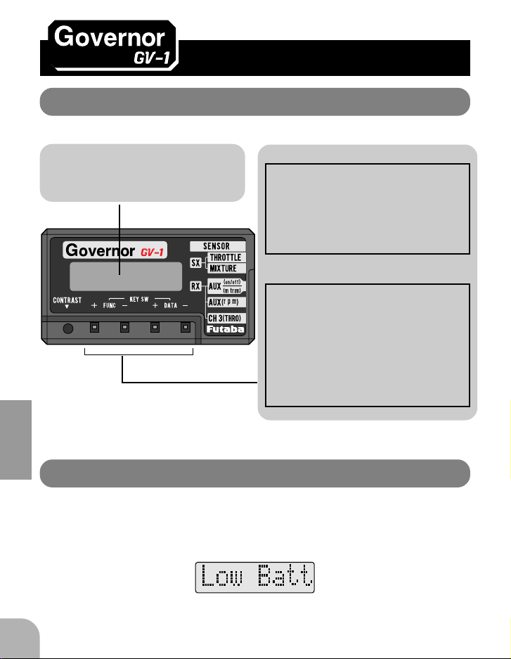
FUNCTIONS
LCD display and edit keys
LCD panel Edit keys
The set-up data can be displayed
and the governor operating state
can be monitored.
FUNCTIONS
Set-up screen call
The set-up screens can be sequentially called with the FUNC+ and
FUNC- keys. The order in which
the set-up screens are called,
please see the function map.
Data setting
Data is set with the DATA+ and
DATA- keys. During data setting,
the DATA+ key increases the
data and the DATA- key decreases the data. The mode can be
selected with either the DATA+
or DATA- key.
Low battery alarm
When the battery voltage drops to 3.8V, "Low Batt" is displayed. When this
message appears, immediately stop using the model and recharge the Nicd
battery.
2424
24
2424
Page 23

Function map
FUNC+ key FUNC- key
(Initial screen)
Note 1
Speed
functions
Governor
ON/OFF
functions
Battery
voltage check
Mixture
functions
Battery
fail safe
functions
Operating
range setting
functions
Sensor check
rpm
Max
rSx
Disp
GRt
SWPt
StSw
SWCd
GvOf
Volt
MxMD
MD
ATV
MSx
MTrm
B/FS
B/FD
Lmt
Tst
Sen
Speed display (monitor function) (P33)
MAX speed display (monitor function) (P33)
Speed setting (P34)
Speed display mode (P35)
Rotor gear ratio (P35)
Governor ON/OFF switch position setting (P36)
Governor ON/OFF stick operation setting (P37)
Governor ON/OFF condition (monitor function) (P37)
Governor OFF high point stick operation setting (P38)
Battery voltage display (monitor function) (P38)
Mixture servo operation mode (P39)
Mixture rate setting (P40)
Mixture ATV (P42)
Mixture servo reverse (P42)
Mixture trim (P43)
Battery fail safe (P44)
Battery fail safe position (P44)
Limit setting (P45)
Throttle servo operation test (P46)
Rotation sensor monitor (monitor function) (P46)
FUNCTIONS
Note 1.
The "Limit Set" screen is displayed only when the power is turned on for the
first time after the GV-1 is purchased. Once limit setting is performed, the
"Speed display" screen becomes the initial screen.
2525
25
2525
Page 24

Initial setting for governor operation
When using the governor for the first time, or when the throttle linkage or the
fuselage was changed, always perform this initial setting. The set data are
saved even when the power is turned off.
Throttle limit setting
(Governor idle/high/stop points setting)
1Call the "limit set" screen with the
FUNC+ or FUNC- key.
2Set the throttle stick to the maximum slow position
and press the DATA+ or DATA- key.
The "Idle" display stops flashing and changes to a steady light and
FUNCTIONS
the idle point is memorized.
3Set the throttle stick to the full high position and
press the DATA+ or DATA- key.
The "High" display stops flashing and changes to a steady light and
the high point is memorized.
4Set the throttle stick to the engine cut position and
press the DATA+ or DATA- key.
The "Stop" display stops flashing and changes to a steady light and
the stop point is memorized.
Setting error display
-Set the servo travel to ATV50% or more. If the servo travel is set to less
than 50%, "-ERR-" will be displayed. Increase the servo travel and reset
the throttle linkage. (Note: The closer to 100% ATV is the best condition)
-Always set the stop point to a position lower than the idle point. If the stop
point is set to a position higher than the idle point, "-ERR-" will be displayed. If this occurs, set the stop point to a position lower than the idle
point and reset the throttle limit.
2626
26
2626
Page 25
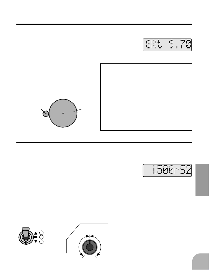
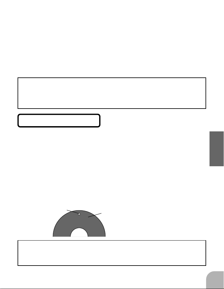
Rotor gear ratio setting
(Rotor gear ratio input)
1Call the "rotor gear ratio" screen
with the FUNC+ or FUNC- KEY.
2Input the gear ratio
from the DATA+ or
DATA- key.
The rotor gear ratio can be
input in 1/100 steps.
Engine
pinion gear
N2
Rotor
main gear
N1
Notes:
-If the gear ratio is not properly set, the set
speed and actual engine speed will be different.
-The gear ratio should be given in the helicopter instruction manual. If the helicopter instruction manual does not give the
gear ratio, calculate the gear ratio as fol-
lows:
Gear ratio = N1/N2
Carry values less than 1/1000 to the next
whole number.
Speed setting (Set at control amp)
Three speeds can be set. This is standard when the speed is switched by 3position switch. A 2-position switch and a VR channel can also be used.
1Call the "speed set-up" screen
with the FUNC+ or FUNC- key.
(When switch used)
2Set the switch to the de-
sired position and set the
speed with the DATA+ or
DATA- key.
1
3 points
2
can be set
3
clockwise
Center
Counter
(When VR channel used)
2Set the variable resistor
knob to the fully counterclockwise, center, or fully
clockwise position and
set the speed with the
DATA+ or DATA- key.
3 points
can be set
Clockwise
FUNCTIONS
2727
27
2727
Page 26

Set the speed of each point by repeating step "2".
The set points can be verified at "rSx" (x=1,2,3) of the
display screen.
Note:
When the speed setting channel travel (ATV, AFR) is made 20% or less,
points 1 and 3 cannot be set.
Speed setting points
The engine maximum speed range limits the maximum speed setting.
Test fly the helicopter with the governor turned off and tach the main rotor
R.P.M. while in horizonal flight. This is the maximum R.P.M. that can be
achieved with the engine and pitch setup that you are using. Please set the
governor maximum speed to approximately 50 R.P.M.'s less. (Example: If
1800 R.P.M.'s is max then set governor to 1750)
FUNCTIONS
The maximum speed can be verified at the MAX. speed display, however
this could show some unlocked main rotor condition which is not accurate.
Reference
The transmitter ATV function can also be used to change the point 1 and
point 3 speed settings to a certain extent. The amount of this change is
proportional to the difference between the point 1 and point 3 set speed and
the point 2 set speed. For example, if point 1 is set to 1300rpm and point 2
is set to 1500rpm, and the transmitter ATV is changed from 20 to 100%,
the point 1 speed will change from 1460 to 1300rpm. The transmitter ATV
function has very little effect on the point 2 speed setting.
2828
28
2828
Speed
Neutral
Point 1
rs1
Point 2
rs2
Speed setting
channel travel
Point 3
rs3
The speed changes linearly on a line
connecting points 1, 2, and 3.
Page 27
Governor ON/OFF operation mode setting
A. When governor turned on and off by on/off switch
1Call the "governor on/off switch
position set-up" screen with the
FUNC+ or FUNC- key.
2Operate the ON/OFF switch and verify the ON/
OFF directions at the LCD display.
3Use the DATA+ or DATA- key to change the
switch ON/OFF directions.
Reference
When you do not want to turn off the governor at the slow position of the
throttle stick to perform inverted flight, rolls, and other aerobatics, select
INH at the "governor ON/OFF stick operation set-up" (StSw) screen.
B. When using together with speed setting switch
(When using the mixture trim function and when there is no vacant
channel)
1Call the "speed set-up" screen
with the FUNC+ or a FUNC- key.
FUNCTIONS
2Set the switch to the position to be used as the off
position and set the speed to 1000rpm or less with
the DATA+ or DATA- key.
3"off" is displayed and the governor can be turned
off at that position.
2929
29
2929
Page 28

C. When linked with throttle stick
(When there is no vacant channel)
1Call the "governor on/off stick op-
eration set-up" screen with the
FUNC+ or FUNC- key.
2Switch the display from INH to on/off with the
DATA+ or DATA- key.
When the stick switch is operated, the display switches from
"off" to "on" and the switching point can be checked.
3When the throttle stick is set 15% or less from the
slow side, the governor is turned on.
FUNCTIONS
Until the start of flight, keep the governor in the off state
with the throttle stick at 15% or less from the slow side.
This is the engine starting, etc. mode. If the throttle stick is set to the ON position
when the engine speeds exceeds 70% of the set speed, the governor will be
unintentionally turned on.
Battery fail safe setting
Always perform battery fail safe setting at the governor.
When used, the governor controls the throttle. Therefore, the battery fail safe
function normally set in a PCM transmitter is not performed.
3030
30
3030
Page 29

1Call the "battery fail safe" screen
with the FUNC+ or FUNC- key.
2Set the battery fail safe window to
"ACT" with the DATA+ or DATAkey.
3Call the "battery fail safe position"
window with the FUNC+ or
FUNC- key.
4Set the throttle stick to the desired position and
press the DATA+ or DATA- key.
5The battery fail safe position is memorized.
When the throttle stick is operated, "*" is displayed at the set
position and the set position can be verified.
Fail safe data setting
Set the throttle channel fail safe function as described below.
When used, the governor controls the throttle. Therefore, the throttle channel
fail safe function normally set in a PCM transmitter is not performed.
FUNCTIONS
Transmitter side setting
Use the fail safe function of the channel that turns the governor on and off
to set the fail safe position to the point at which the governor is turned off.
With this setting, when the system enters the fail safe state, the governor is
turned off and the receiver throttle signal is output directly.
3131
31
3131
Page 30

Speed sensor output check
Check the sensor output not only when installing the sensor but periodically.
Since the magnet rotates at high speed, it is subjected to a large centrifugal
force. Check the magnet output and mounting state after about every 10 flights.
1Call the "sensor percentage"
screen with a the FUNC+ or
FUNC- key.
2Position the magnet directly below the sensor.
FUNCTIONS
If 60% or more is displayed on the Sen screen, the sensor
output is OK.
3Move the magnet away from the sensor.
If 10% or less is displayed on the Sen screen, the sensor
output is OK.
If the display is less than 60% when the magnet is directly below the sensor, bring the sensor closer to the magnet so that the 60% or more is displayed. The magnet and sensor gap criteria is approximately 1 to 2mm. If a
sensor output is not obtained even when the sensor is brought close to the
magnet, the magnet and sensor center positions may have changed.
3232
32
3232
Page 31
Description of functions
The following describes, in display order, the functions which can be set or
monitored with the GV1. The functions are described from the called state.
The functions can be sequentially called with the FUNC (+ or -) keys.
Speed display (monitor function) rpm
This function displays the engine speed or rotor speed.
When the governor is on, "rpm" is highlighted and flashed. When the speed
comes within about 2% of the set speed, "rpm" lights steadily. When the
speed reaches approximately +1% of the set speed, the display changes to
"rpL", which indicates the locked state.
When checking the speed, be sure not to get too close to
the helicopter.
The display can be switched between engine and rotor with the "speed
display mode" set-up screen.
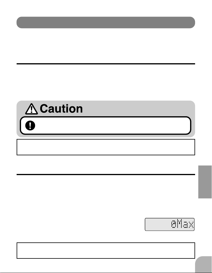
MAX speed display (monitor function) Max
This function displays the maximum engine speed or rotor speed. It can be
used to check the engine power. However, the maximum speed when the
throttle stick is 95% or more from the high side is memorized. The maximum
value is memorized while the power is on.
(Reset method)
FUNCTIONS
1Hold down the DATA+ or DATA-
key for at least 2 seconds, or turn
off the power.
The display can be switched between engine and rotor with the "speed
display mode" set-up screen.
3333
33
3333
Page 32
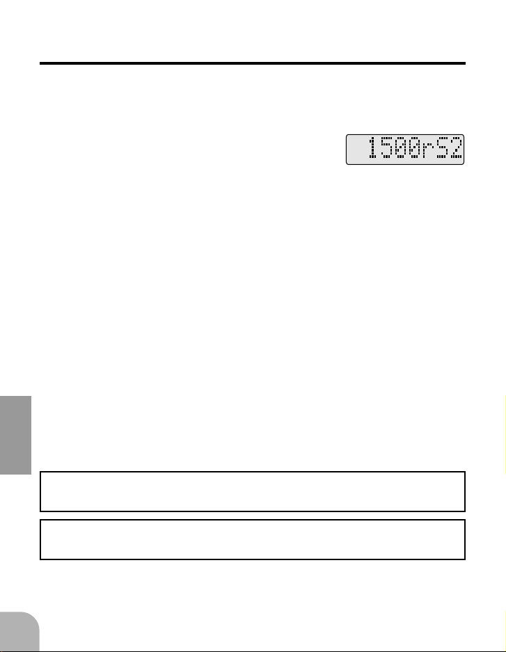
Speed setting rS1~rS3
The speed can be set for three points.
Connect the speed setting input "AUX(r.p.m)" to a receiver vacant channel.
(Set value check)
1Operate the switch (3-position), or
variable resistor knob.
The set values are displayed on the LCD screen in rS1->rS2>rS3 (slow->medium->high) order.
(Speed setting method)
1Set the switch or variable resistor knob to the de-
sired position and set the speed of that point by
pressing the DATA+ key (accelerate) or DATA-
FUNCTIONS
key (decelerate).
-When not using the speed setting channel, set rS2 only.
rS1 and rS3 are disabled.
-When using a 2-position switch, set rS1 and rS3 only. rS2 is
set to the initial value (1500rpm).
(Setting range) 1000~2100rpm
(Initial value) rS1:1300rpm rS2:1500rpm rS3:1700rpm
Reference
If the speed is set to 1000rpm or less, the display will change to "-Off-" and
the governor can be turned off at that switch position.
The engine and rotor displays can be switched with the "[speed display
mode" set-up screen.
3434
34
3434
Page 33
Speed display mode Disp
The speed display mode can be changed. Engine speed display (Eng) or rotor
speed display (Rot) can be selected.
(Mode switching)
1The display is switched each time
the DATA+ or DATA- key is
pressed.
(Initial value) Rot
Rotor gear ratio GRt
This function inputs the gear ratio between the main rotor and the engine to
display the rotor speed.
(Input method)
1Input the gear ratio by pressing
the DATA+ key (increase) or
DATA- key (decrease).
(Setting range) 3.00~15.00 in 1/100 steps
(Initial value) 9.70
FUNCTIONS
3535
35
3535
Page 34

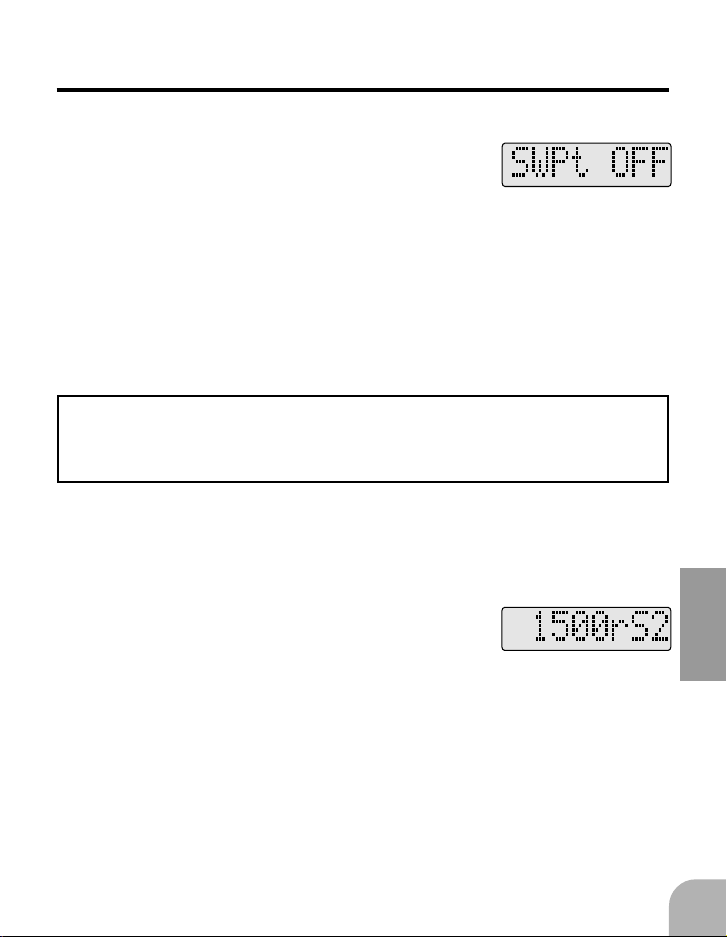
Governor ON/OFF switch position setting
This set-up screen sets the direction of operation of the
switch when the governor is turned on and off with the
transmitter switch. The governor on/off input "AUX(on/
off)" connects to a receiver vacant channel.
(Setting direction check)
SWPt
1Operate the switch.
The "off" or "on" set direction is displayed
on the LCD screen.
(Changing the direction)
1Change the direction by pressing the DATA+ or
DATA- key.
FUNCTIONS
(Initial value) Normal mode
Function priority
The "governor ON/OFF switch position set-up" and "mixture trim" functions cannot be enabled simultaneously. Therefore, when the "governor
ON/OFF switch position set-up" function was enabled, always INH the
"mixture trim" function. Moreover, always set the "mixture servo operation mode" to the "Gov" mode.
3636
36
3636
Page 35

Governor ON/OFF switch operation setting
If the governor is turned on and off by using the throttle
stick position, then by selecting. "INH" inhibit it willturn
off the governor at the maximum slow position. When this
function is set to the side at which on/off switching is performed, when "OFF" is displayed, the governor is off and
when "ON" is displayed, the governor is on and can be operated.
StSw
(Setting method)
1Switch the mode by pressing the
DATA+ or DATA- key.
(Initial value) INH
Governor ON/OFF condition
(monitor function) SWCd
This function displays the present governor on/off status. When the governor
can be operated, "ON" is displayed. This function checks all the conditions
for turning the governor on and off.
FUNCTIONS
3737
37
3737
Page 36

Setting of Governor OFF at high stick position
The governor can be turned off at the high side from the set
point. However, this function is only effective when the
speed is set to 1600rpm or more. It will not operate even if
the speed is set to a value lower than this.
(Setting method)
GvOf
1Set the point by pressing the
DATA+ key (increase) or DATAkey (decrease).
(Setting range) 70~100%
At 100%, the display changes to "INH" and the governor remains on all the time.
(Initial value) INH
FUNCTIONS
Note:
When the governor set speed and the engine speed at the point at which the
governor is turned off are considerably different, the speed variation when
the engine speed shifts from the governor off point back to the governor on
point will be large. Therefore, adjust the off point, or the set speed, so that
the governor off point speed and governor set speed are the same.
Battery voltage display (monitor function)
This function displays the present battery voltage.
When the battery voltage drops to 3.8V, the battery alarm
"Low Batt" flashes.
3838
38
3838
Volt
Page 37

Mixture servo operation mode MxMD
The mixture servo must operate in proportion to operation of the throttle
servo. When a governor is used, the throttle servo is controlled by the governor. Therefore, the governor must generate the mixture signal.
The mixture operation mode can be selected.
When the "Gov" mixture servo operation mode is selected, the mixture servo
operates on a 9-point curve set by the governor. Set the rate of each point with
the "mixture rate set-up" function.
The "Dir" mode sets the curve at the transmitter in the governor off state to
simplify mixture curve setting. It is used by setting the transmitter fuel mixture control function to "ACT". The curve data set at the transmitter controls
the mixture servo. The mixture servo can be operated by copying the mixture
curve. The AUX (m.trm) connector connects to the mixture channel. The setting of each point is called from the transmitter with the "mixture rate set-up"
function. In this mode, curve data from the transmitter can be set for nine
points.
The "Dir" mode is used in mixture curve initial setting. Since operation is
linked with the throttle stick and not with the governor, after curve setting,
switch to the "Gov" mode. Not all Futaba transmitters have Fuel Mixture
Function (FMC), however it is not necessary since the GV-1 has a mixture
control function.
(Mode selection)
FUNCTIONS
1Select the mode by pressing the
DATA+ or DATA- key.
(Initial value) Gov
3939
39
3939
Page 38

Note:
Setting the "Dir" mode disables the "governor ON/OFF switch" function.
In the "Dir" mode, always set the "mixture trim" function to INH.
In the "Gov" mode, when the mixture trim function is ACT, the AUX
(m.trm) connector becomes the mixture trim and when the mixture trim
function is INH, the AUX (m.trm) connector becomes the governor ON/
OFF switch input. Therefore, in the "Dir" mode, when the mixture curve
input signal was used, operation is performed with this signal.
Mixture rate setting MGx/MDx
Each point of the mixture curve can be set. When the "Gov" mode is set with
FUNCTIONS
the "mixture servo operation mode" function, "MGx" is displayed and when
the "Dir" mode is set with the "mixture servo operation mode" function,
"MDx" is displayed at each point. ("x"shows the number of characters of each
point.) Nine points can be set.
(Setting method)
1With the governor in the off state,
move the throttle stick to the set
point.
4040
40
4040
At points other than the set point, "->" or "-<" is displayed to
indicate the direction of offset from the set point.
When the set point is reached, the rate display changes from
flashing to a steady light to show that setting is possible.
Page 39

("Gov" mode)
("Dir" mode)
2Set the rate with the
DATA+ key (increase) or
DATA- key (decrease).
2Transfer the mixture
curve data of that point
from the transmitter by
pressing the DATA+ or
DATA- key.
However, to match the mixture
curve data with the transmitter
curve data as final servo output,
match the "ATV" data of the mixture channel set at the transmitter
and the governor side "mixture
ATV" data and servo reverse
function.
(Setting range) 0~100%
(Initial value) MD1:15% MD2:36% MD3:50% MD4:58% MD5:64%
MD6:68% MD7:73% MD8:76% MD9:80%
FUNCTIONS
4141
41
4141
Page 40

Mixture ATV ATV
Sets the mixture servo throw.
Set the operation angle in accordance with the mixture carburetor instruction
manual.
(Setting method)
1Operate the throttle stick and se-
lect "ATVA" (slow side) or "ATVB"
(high side.)
2Set the steering angle by pressing the DATA+ key
(increase) or DATA- key (decrease).
(Setting range) 10~140%
FUNCTIONS
(Initial value) ATVA100% ATVB100%
Mixture servo reverse MSx
The direction of operation of the mixture servo can be reversed.
(Setting method)
1Switch the direction by pressing
the DATA+ or DATA- key.
(Initial value) Norm
4242
42
4242
Page 41
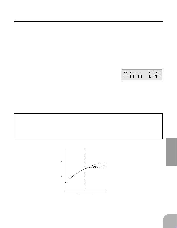
Mixture trim MTrm
Set when you want to use a vacant volume channel to use the mixture servo
trim function. "INH" disables the mixture trim function. To use the trim function, set MTrm to "ACT" and connect the AUX (m.trim) connector to the
vacant channel you want to use.
Trim operates when the mixture servo is above the neutral position. Adjust
the trim servo travel with ATV of the transmitter AUX channel.
(Setting method)
1Set the mode by pressing the
DATA+ or DATA- key.
(Initial value) INH
Functions priority
The "mixture trim" and "governor ON/OFF switch position setting" functions cannot be active at the same time. Therefore, when activating the
"mixture trim" function, inhibit the "governor ON/OFF switch position
setting" function.
FUNCTIONS
Close Open
Slow High
50%
Trim
deflection
Throttle
servo
4343
43
4343
Page 42

Battery fail safe B/FS
The battery fail safe function can be activated and inhibited.
"INH" inhibits the battery fail safe function and "ACT" activates the battery
safe function. When activating the battery fail safe function, set the servo
position with the "battery fail safe position" function.
(Setting method)
1Set the mode by pressing the
DATA+ or DATA- key.
(Initial value) INH
Battery fail safe position B/FD
This function sets the throttle position during battery fail safe operation.
When the battery voltage drops to 3.8V, the system enters the battery fail safe
FUNCTIONS
mode. Moving the throttle stick to the maximum slow position after battery
fail safe operation temporarily resets the battery fail safe function. However,
30 seconds later, the system enters the battery fail safe mode again. Once the
system enters the battery fail safe mode, this operation continues until the
power is turned off.
(Setting method)
1Move the throttle stick to the de-
sired position and memorize the
throttle position at battery fail safe
operation by pressing the DATA+
or DATA- key.
(Initial value) 20%
(Set point confirmation)
1When the throttle stick is operated, "*" is displayed
at the set point and the set point can be confirmed.
4444
44
4444
Page 43
Limit set Lmt
This function sets the governor control range.
When using the governor for the first time, and when the
servo throw was changed, always perform limit setting
again.
(Limit setting method)
1When"Idle" is flashing, set the
throttle stick to the maximum slow
position and press the DATA+ or
DATA- key.
About 1 second later, "High" begins to flash.
2When"High" is flashing, move the
throttle stick to the full high position and press the DATA+ or
DATA- key.
About 1 second later, "Stop" begins to flash.
FUNCTIONS
3When"Stop" is blinking, move the
throttle stick and cut switch to the
engine cut position and press a
DATA (+ or -) key.
This completes idle/high/stop point setting.
(Initial values) Low:1930us High:1110uS Stop:2070uS
4545
45
4545
Page 44

Error display
When adjusting the throttle linkage make sure that ATV and AFR are set to
50% or greater otherwise the GV-1 will not operate and "-ERR-" will be
displayed. Also when setting the "Stop"position make sure it is not higher
than idle or the "-ERR-" will be displayed.
Throttle servo operation test Tst
The servo operating position set with the "limit set" function can be checked.
(Check method)
1Each time the DATA+ or DATA-
key is pressed, the throttle servo
FUNCTIONS
moves to the Idle->High->Stop
point set position.
Rotation sensor monitor (monitor function)
The rotation sensor signal level can be checked.
(Monitoring method)
Sen
1Bring the magnet near the sensor.
4646
46
4646
The signal level is displayed on the LCD screen.If the display
is 60% or more, the speed can be normally picked up. If less
than 60% is displayed, adjust the sensor position.
Page 45

REFERENCE
Specifications and ratings are subject to change without prior notice.
Specifications
-Control system: Digital advanced control
-Speed pick-up: Direct detection of engine rotation by magnetic
sensor
-Control resolution: 0.1Hz (+6rpm: engine speed)
-Speed stability accuracy: 1%
-Control response: 20mS
-Speed control range: 1000~2100rpm (rotor speed)
-Speed setting: Key input (10 turns step) Transmitter setting (1
turn step)
-Display: 8 characters dot matrix liquid crystal display
-Mixture curve: 9 points settable
-Operating voltage range: DC 3.8V~6.0V
-Current drain: 40mA (at 4.8V, including sensor)
-Size: 56.5x30.5x16mm (body), 7.5x10x16mm (sensor)
-Weight: 34g (body), 4g (sensor)
REFERENCE
4747
47
4747
Page 46

Glossary
The Glossary gives the definition and the number of the page that describes
the related function for the symbols used in this manual.
2P 2-position (switch)
3P 3-position (switch)
A
ACT Activate
AFR AFR function
ATV ATV function P42
AUX Spare channel.
B
B/FS Battery fail safe P44
B/FD B/FS position setting P44
C
CH Channel
CONTRAST Contrast adjustment
D
DATA Data input key P24
DC Direct current
Dir Direct mode P39
Disp Speed display function P35
E
-ERR- Data setting error display
F
FUNC Function selection key P24
REFERENCE
G
Gov, GOV Governor
Governor Governor
GRt Rotor gear ratio P35
GV-1 Model No. of this governor
GvOf Governor off high point stick
position operation setting P38
H
High High point P45
I
Idle Idle point P45
INH Inhibits operation
K
KEYSW Edit key
L
LCD Liquid crystal display
Lmt Limit setting function P45
Low Batt Battery alarm
4848
48
4848
M
m.trim Mixture trim
Max MAX speed display function P33
MD Mixture rate setting function P40
MG Mixture rate setting function P40
MIXTURE Fuel mixture
MSx Mixture servo reverse P42
MTm Mixture trim P43
MxMD Mixture servo operation mode
P39
MXTR Mixture
N
Norm Normal side
O
on on
off off
P
PCM Pulse code modulation
R
Rev Reverse side
RH Relative humidity
rpm, r.p.m. Speed (revolutions)
rS1,rS2,rS3 Speed setting position
RX Receiver
S
Sen Rotation sensor monitor P46
SENSOR Sensor
Stop Stop point P45
Stsw Governor on/off stick operation
setting P37
SWCd Governor on/off condition P37
SWPt Governor on/off switch position
setting P36
SX Servo
T
THRO,THROTTLE Throttle
Tst Throttle servo operation test P46
Tx Transmitter
V
Volt Unit of voltage
VR Variable resistor
Page 47

GV-1 PARAMETERS SHEET
Helicopter:
Engine: Date:
Parameter Initial value Set value
Speed 1 (rS1)
Speed 2 (rS2)
Speed 3 (rS3)
Speed display (Disp)
Rotor gear ratio (GRt)
Mixture trim (MTrm)
Stick ON/OFF mode (StSw)
Governor high side off (GvoF)
Mixture rate
MD1
1300rpm
1500rpm
1700rpm
Rotor
9.70
INH
INH
INH
15%
*Please copy and use.
Remarks
rpm
rpm
rpm
%
MD2
MD3
MD4
MD5
MD6
MD7
MD8
MD9
Mixture servo reverse (MSx)
36%
50%
58%
64%
68%
73%
76%
80%
norm
%
%
%
%
%
%
%
%
REFERENCE
4949
49
4949
Page 48

REPAIR SERVICE
Before requesting repair, read this instruction manual again and recheck your
system. Should the problem continue, request repair service as follows:
Describe the problem in as much detail as possible and send it with
a detailed packing list together with the parts that require service.
• Symptom (Including when the problem occurred)
• System(Transmitter, Receiver, Servo's and model numbers)
• Model (Model name)
• Model Numbers and Quantity
• Your Name, Address, and Telephone Number.
• Dated Proof of Purchase (For Warranty Claims)
Please read the warranty card supplied with your system.
When requesting warranty, please send the card along with some
type of dated proof of purchase.
If you have any questions regarding this product, please consult
your local hobby dealer or contact the Futaba Service Center.
REFERENCE
5050
50
5050
Page 49

FUTABA CORPORATION
Makuhari Techno Garden Bldg., B6F 1-3 Nakase, Mihama-ku, Chiba 261-8555, Japan
Phone: (043) 296-5119 Facsimile: (043) 296-5124
REFERENCE
©FUTABA CORPORATION 1999,03
5151
51
5151
 Loading...