

Page 1

18-CHANNEL COMPUTER SYSTEMS
Condition 1
+0+0+0
+0 +0
'11/11/11
INSTRUCTION MANUAL
1M23N26403
Page 2
TABLE OF CONTENTS
INTRODUCTION............................................... 4
●Support and Service ......................................... 4
●Application, Export, and Modication ........... 5
●Denitions of Symbols ...................................... 6
●Safety Precautions (do not operate without
reading) ............................................................. 6
BEFORE USE ................................................... 10
●Features of 18MZ............................................ 10
●Contents and Technical Specications .......... 12
●Accessories ....................................................... 13
●Transmitter controls ....................................... 14
Cautions on handling antenna .......................... 14
LED monitor .................................................... 15
Switch reallocation (SA-SH) ........................... 15
Volume (LD, CD, RD) ..................................... 16
Slide Lever (LST, LS, RS, RST) ...................... 16
Digital trim (T1-T6) ......................................... 17
Touch panel / Rotary key / Direct key ............. 17
Stick Adjustment .............................................. 18
Battery exchange .............................................. 19
Back lid ............................................................ 21
Connector / Plug ............................................... 22
SD card / USB port .......................................... 23
Camera function ............................................... 24
BASIC OPERATION ....................................... 34
●Battery Charging ............................................ 34
●How to turn ON/OFF the transmitter ..........35
When turning on ............................................... 35
When turning off .............................................. 35
How to reset ..................................................... 36
●Registration of the user's name ..................... 36
●Home screen .................................................... 37
●Home 2 screen ................................................. 38
●User Menu ....................................................... 38
FUNCTIONS OF SYSTEM MENU ................ 39
Trainer .............................................................. 40
Display ............................................................. 43
Date & Time ..................................................... 44
User Name ........................................................ 45
Switch ............................................................... 46
H/W Setting ...................................................... 47
Sound Volume ................................................. 49
Player .............................................................. 50
Camera ............................................................. 51
S.BUS Servo ................................................... 52
Information ...................................................... 55
Range Check ................................................... 56
●Receiver R7008SB nomenclature .................. 25
Connector ......................................................... 25
S.BUS2 Connector ........................................... 25
Link / Mode Switch .......................................... 25
Extra Voltage Connector .................................. 25
R7008SB CH Mode ......................................... 26
●Servo(Option) / Toolbox ................................. 27
●Receiver's Antenna Installation .....................28
●Safety precautions when installing receiver and
servos ............................................................... 29
●S.BUS Installation ........................................... 30
●S.BUS Wiring example ..................................31
●S.BUS2 System.............................................. 32
●S.BUS device setting ..................................... 32
●Telemetry System ............................................ 33
TABLE OF CONTENTS
<
2
>
MODEL BASIC SETTING PROCEDURE ...57
●Airplane/glider basic setting procedure ........57
●Helicopter basic setting procedure ................ 59
●Receiver and servos connection ..................... 63
●Servo connection by model type .................... 64
FUNCTIONS OF LINKAGE MENU ............. 69
Servo Monitor .................................................. 70
Model Select .................................................... 71
Model Type ...................................................... 72
Picture .............................................................. 74
Sound ............................................................... 75
System Type ..................................................... 77
System Type selection
Receiver linking
.............................................
....................................................
77
77
Page 3
Dual receiver function
Telemetry function
D/L Interval
Battery fail-safe voltage setup
Linking method (T18MZ ↔ R7008SB)
The example for choosing System Type
..........................................................
............................................
.................................................
..................................
......................
......................
77
77
77
77
78
79
Function ........................................................... 80
Sub-Trim .......................................................... 82
Servo Reverse .................................................. 83
Fail Safe ........................................................... 84
End Point (ATV) .............................................. 85
Throttle Cut (Airplane/helicopter only) ........... 86
Idle Down (Airplane/helicopter only) .............. 87
Swash Ring (Helicopter only) .......................... 88
Swash (Helicopter only) ................................... 89
Timer ................................................................ 91
Dial Monitor ..................................................... 92
Function Name ................................................. 93
Telemetry .......................................................... 94
Sensor ............................................................... 97
Warning ............................................................ 99
Data Reset ...................................................... 100
Codition Hold (Helicopter only) .................... 101
Trim Mix 1/2 .................................................. 125
Airbrake ......................................................... 127
Gyro ............................................................... 129
V-tail ............................................................... 130
Ailevator ......................................................... 131
Winglet ........................................................... 132
Motor .............................................................. 133
RUD to ELE ................................................... 134
Snap Roll ........................................................ 135
Multi Engine .................................................. 136
Accelerration .................................................. 137
●Helicopter Functions .................................... 138
PIT Curve ....................................................... 139
THR Curve ..................................................... 142
Acceleration ................................................... 144
Throttle Hold .................................................. 145
Swash Mix ...................................................... 146
Throttle Mix ................................................... 147
PIT to Needle ................................................. 148
PIT to RUD .................................................... 149
Gyro ............................................................... 150
Governor ........................................................ 151
Throttle Limiter .............................................. 152
FUNCTIONS OF MODEL MENU ............... 102
Servo Monitor (Linkage Menu 70)
Condition Select ............................................. 103
AFR (D/R) ...................................................... 105
Prog. Mixes .................................................... 107
Fuel Mixture ................................................... 109
●Airplane/Glider/EP Glider Functions ......... 110
AIL Differential .............................................. 112
Flap Setting .................................................... 113
AIL to Camber FLP ........................................ 114
AIL to Brake FLP ........................................... 115
AIL to RUD .................................................... 116
Airbrake to ELE ............................................. 117
RUD to AIL .................................................... 118
Camber Mix ................................................... 119
ELE to Camber ............................................... 121
Camber FLP to ELE ....................................... 122
Buttery ......................................................... 123
COMMON OPERATIONS USED IN
FUNCTION SETUP SCREEN ......................153
UPDATING...................................................... 163
T14MZ →T18MZ MODEL DATA
CONVERSION ............................................... 164
TABLE OF CONTENTS
<
>
3
Page 4

INTRODUCTION
®
Thank you for purchasing a Futaba
FASSTest-2.4GHz* 18MZ series digital proportional R/C system. This
system is extremely versatile and may be used by beginners and pros alike. In order for you to make the best use
of your system and to y safely, please read this manual carefully. If you have any difculties while using your
system, please consult the manual, our online Frequently Asked Questions (on the web pages referenced below),
your hobby dealer, or the Futaba Service Center.
Due to unforeseen changes in production procedures, the information contained in this manual is subject to
change without notice.
Support and Service: It is recommended to have your Futaba equipment serviced annually during your hobby’s
“off season” to ensure safe operation.
IN NORTH AMERICA
Please feel free to contact the Futaba Service Center for assistance in operation, use and programming. Please
be sure to regularly visit the 18MZ Frequently Asked Questions web site at www.futaba-rc.com/faq/. This page
includes extensive programming, use, set up and safety information on the 18MZ radio system and is updated
regularly. Any technical updates and US manual corrections will be available on this web page. If you do not
nd the answers to your questions there, please see the end of our F.A.Q. area for information on contacting us
via email for the most rapid and convenient response.
Don’t have Internet access? Internet access is available at no charge at most public libraries, schools, and other
public resources. We nd internet support to be a fabulous reference for many modelers as items can be printed
and saved for future reference, and can be accessed at any hour of the day, night, weekend or holiday. If you do
not wish to access the internet for information, however, don’t worry. Our support teams are available Monday
through Friday 8-5 Central time to assist you.
FOR SERVICE ONLY:
Futaba Service Center
3002 N. Apollo Drive, Suite 1
Champaign, IL 61822
Phone: 217-398-0007
www.futaba-rc.com/service.html
(PROGRAMMING AND USER QUESTIONS)
Please start here for answers to most questions:
FOR SUPPORT :
www.futaba-rc.com/faq/
Fax: 217-398-7721
Phone: 217-398-8970 option 2
Email: service@futaba-rc.com
OUTSIDE NORTH AMERICA
Please contact your Futaba importer in your region of the world to assist you with any questions, problems or
service needs.
Please recognize that all information in this manual, and all support availability, is based upon the systems sold
in North America only. Products purchased elsewhere may vary. Always contact your region’s support center for
assistance.
<Introduction>
4
Page 5
Application, Export, and Modication
1. This product may be used for model airplane or surface (boat, car, robot) use. It is not intended for use in
any application other than the control of models for hobby and recreational purposes. The product is subject to
regulations of the Ministry of Radio/Telecommunications and is restricted under Japanese law to such purposes.
2. Exportation precautions:
(a) When this product is exported from the country of manufacture, its use is to be approved by the laws
governing the country of destination which govern devices that emit radio frequencies. If this product is then reexported to other countries, it may be subject to restrictions on such export. Prior approval of the appropriate
government authorities may be required. If you have purchased this product from an exporter outside your
country, and not the authorized Futaba distributor in your country, please contact the seller immediately to
determine if such export regulations have been met.
(b) Use of this product with other than models may be restricted by Export and Trade Control Regulations, and
an application for export approval must be submitted. This equipment must not be utilized to operate equipment
other than radio controlled models.
3. Modication, adjustment, and replacement of parts: Futaba is not responsible for unauthorized modication,
adjustment, and replacement of parts on this product. Any such changes may void the warranty.
Compliance Information Statement (for U.S.A.)
This device, trade name Futaba Corporation of America, model number R7008SB, complies with part 15 of the
FCC Rules. Operation is subject to the following two conditions:
(1) This device may not cause harmful interference, and
(2) This device must accept any interference received, including interference that may cause undesired
operation.
The responsible party of this device compliance is:
Futaba Service Center
3002 N Apollo Drive Suite 1, Champaign, IL 61822 U.S.A.
TEL (217)398-8970 or E-mail: support@futaba-rc.com (Support)
TEL (217)398-0007 or E-mail: service@futaba-rc.com (Service)
The RBRC. SEAL on the nickel-cadmium battery contained in Futaba products indicates that
Futaba Corporation of America is voluntarily participating in an industry-wide program to collect
and recycle these batteries at the end of their useful lives, when taken out of service within the
United States. The RBRC. program provides a convenient alternative to placing used nickelcadmium batteries into the trash or municipal waste system, which is illegal in some areas.
(for USA)
You may contact your local recycling center for information on where to return the spent battery. Please
call 1-800-8BATTERY for information on Ni-Cd battery recycling in your area. Futaba Corporation of
America's involvement in this program is part of its commitment to protecting our environment and conserving
natural resources.
*RBRC is a trademark of the Rechargeable Battery Recycling Corporation.
<Introduction>
5
Page 6
Federal Communications Commission Interference Statement (for U.S.A.)
This equipment has been tested and found to comply with the limits for a Class B digital device, pursuant to Part
15 of the FCC Rules. These limits are designed to provide reasonable protection against harmful interference in
a residential installation.
This equipment generates, uses and can radiate radio frequency energy and, if not installed and used in
accordance with the instructions, may cause harmful interference to radio communications. However, there is
no guarantee that interference will not occur in a particular installation. If this equipment does cause harmful
interference to radio or television reception, which can be determined by turning the equipment off and on, the
user is encouraged to try to correct the interference by one or more of the following measures:
--Reorient or relocate the receiving antenna.
--Increase the separation between the equipment and receiver.
--Connect the equipment into an outlet on a circuit different from that to which the receiver is connected.
--Consult the dealer or an experienced radio/TV technician for help.
CAUTION:
To assure continued FCC compliance:
Any changes or modifications not expressly approved by the grantee of this device could void the user's
authority to operate the equipment.
Exposure to Radio Frequency Radiation
To comply with FCC RF exposure compliance requirements, a separation distance of at least 20cm must be
maintained between the antenna of this device and all persons.
This device must not be co-located or operating in conjunction with any other antenna or transmitter.
Meaning of Special Markings
Pay special attention to safety where indicated by the following marks:
DANGER - Procedures which may lead to dangerous conditions and cause death/serious injury if not
carried out properly.
WARNING - Procedures which may lead to a dangerous condition or cause death or serious injury to
the user if not carried out properly, or procedures where the probability of supercial injury or physical
damage is high.
CAUTION - Procedures where the possibility of serious injury to the user is small, but there is a danger of
injury, or physical damage, if not carried out properly.
= Prohibited = Mandatory
Warning: Always keep electrical components away from small children.
FLYING SAFETY
WARNING
To ensure the safety of yourself and others, please observe the following precautions:
Have regular maintenance performed. Although your 18MZ protects the model memories with non-
volatile EEPROM memory (which does not require periodic replacement) and not a battery, the transmitter
still should have regular checkups for wear and tear. We recommend sending your system to the Futaba
Service Center annually during your non-ying-season for a complete checkup and service.
<Introduction>
6
Page 7
Battery
Charge the batteries! (See Charging the batteries, for details.) Always recharge the transmitter and
receiver batteries before each ying session. A low battery will soon die potentially, causing loss of control
and a crash. When you begin your ying session, reset your T18MZ’s built-in timer, and during the session
pay attention to the duration of usage.
Stop ying long before your batteries become low on charge. Do not rely on your radio’s low battery
warning systems, intended only as a precaution, to tell you when to recharge. Always check your
transmitter and receiver batteries prior to each ight.
Where to Fly
We recommend that you y at a recognized model airplane ying eld. You can nd model clubs and elds
by asking your nearest hobby dealer, or in the US by contacting the Academy of Model Aeronautics.
You can also contact the national Academy of Model Aeronautics (AMA), which has more than 2,500
chartered clubs across the country. Through any one of them, instructor training programs and insured
newcomer training are available. Contact the AMA at the address or toll-free phone number below.
Academy of Model Aeronautics
5161 East Memorial Drive
Muncie, IN 47302
Tele. (800) 435-9262
Fax (765) 289-4248
or via the Internet at http:\\www.modelaircraft.org
Always pay particular attention to the flying field’s rules, as well as the presence and location of
spectators, the wind direction, and any obstacles on the eld. Be very careful ying in areas near power
lines, tall buildings, or communication facilities as there may be radio interference in their vicinity.
<Introduction>
7
Page 8

Lithium polymer(Li-po) Battery Safety and Handling instructions
IMPORTANT!
Use only the Futaba special charger included with this set or other chargers approved by Futaba to
charge the Li-po batteries in the T18MZ transmitter included with this set.
It is important to understand the operating characteristics of Li-po batteries.Always read the specifications
printed on the label of your Li-po battery and charger prior to use. Failure to follow the proceeding precautions
can quickly result in severe, permanent damage to the batteries and its surroundings and possibly result in a
FIRE!
IMPORTANT PRECAUTIONS
Do not attempt to disassemble Li-po packs or cells.
Do not allow Li-po cells to come in contact with moisture or water at any time.
Always provide adequate ventilation around Li-po batteries during charge, discharge, while in use, and
during storage.
Do not leave a Li-po battery unattended at any time while being charged or discharged.
Do not attempt to charge Li-po batteries with a charger that is NOT designed for Li-po batteries, as
permanent damage to the battery and charger could result.
Always charge Li-po batteries in a reproof location. Do not charge or discharge Li-po batteries on carpet,
a cluttered workbench, near paper, plastic, vinyl, leather or wood, or inside an R/C model or full-sized
automobile! Monitor the charge area with a smoke or re alarm.
Do not charge Li-po batteries at currents greater than the “1C” rating of the battery (“C” equals the rated
capacity of the battery).
Do not allow Li-po cells to overheat at any time! Cells which reach greater than 140 degrees Fahrenheit
(60°C) should be placed in a reproof location.
Li-po cells will not charge fully when too cold or show full charge.
It is normal for the batteries to become warm during charging, but if the charger or battery becomes
excessively hot disconnect the battery from the charger immediately!! Always inspect a battery which has
previously overheated for potential damage, and do not re-use if you suspect it has been damaged in any
way.
Do not use a Li-po battery if you suspect physical damage has occurred to the pack. Carefully inspect the
battery for even the smallest of dents, cracks, splits, punctures or damage to the wiring and connectors. DO
NOT allow the battery’s internal electrolyte to get into eyes or on skin—wash affected areas immediately
if they come in contact with the electrolyte. If in doubt, place the battery in a re-proof location for at least
30 minutes.
Do not store batteries near an open ame or heater.
Do not discharge Li-po batteries at currents which exceed the discharge current rating of the battery.
Always store Li-po cells/packs in a secure location away from children.
Secure Digital (SD) Memory Card Handling Instructions
(SD card is not included with this set)
Never remove the SD card or turn off power while
entering data.
Never store the SD card where it may be subject
to strong static electricity or magnetic elds.
Do not expose the SD card to direct sunlight,
excessive humidity or corrosive environments.
<Introduction>
8
Do not expose the SD card to dirt, moisture, water
or uids of any kind.
Be certain to insert the SD card in the correct
direction.
Page 9
At the ying eld
To prevent possible damage to your radio gear, turn the power switches on and off in the proper sequence:
1. Pull throttle stick to idle position, or otherwise disarm your motor/engine.
2. Turn on the transmitter power and allow your transmitter to reach its home screen.
3. Conrm the proper model memory has been selected.
4. Turn on your receiver power.
5. Test all controls. If a servo operates abnormally, don’t attempt to y until you determine the cause of the
problem.
Test to ensure that the FailSafe settings are correct after adjusting them. Turn the transmitter off and
conrm the proper surface/throttle movements. Turn the transmitter back on.
6. Start your engine.
7. Complete a full range check.
8. After ying, bring your throttle stick to idle position, engage any kill switches or otherwise disarm your
motor/engine.
9. Turn off receiver power.
10. Turn off transmitter power.
If you do not turn on your system in this order, you may damage your servos or control surfaces, ood your
engine, or in the case of electric-powered or gasoline-powered models, the engine may unexpectedly turn on
and cause a severe injury.
While you are getting ready to y, if you place your transmitter on the ground, be sure that the wind
won't tip it over. If it is knocked over, the throttle stick may be accidentally moved, causing the engine to
speed up. Also, damage to your transmitter may occur.
In order to maintain complete control of your aircraft it is important that it remains visible at all times.
Flying behind large objects such as buildings, grain bins, etc. is not suggested. Doing so may result in the
reduction of the quality of the radio frequency link to the model.
Do not grasp the transmitter's antenna during ight. Doing so may degrade the quality of the radio
frequency transmission.
As with all radio frequency transmissions, the strongest area of signal transmission is from the sides of the
transmitter's antenna. As such, the antenna should not be pointed directly at the model. If your ying style
creates this situation, easily move the antenna to correct this situation.
As with all radio frequency transmissions, the strongest area of signal transmission is from the sides of the
transmitter's antenna. As such, the antenna should not be pointed directly at the model. If your ying style
creates this situation, easily move the antenna to correct this situation.
<Introduction>
9
Page 10
BEFORE USE
FEATURES
FASSTest system
The T18MZ transmitter adopted the newly developed bidirectional communication system "FASSTest"
Data from the receiver can be checked in your transmitter. FASSTest is a maximum 18 channels (linear 16
channels + switch 2 channels) 2.4GHz dedicated system.
S.BUS2 system
By using the S.BUS2 system multiple servos, gyros and telemetry sensors are easily installed with a
minimum amount of cables.
Windows CE
T18MZ utilizes the world famous Microsoft Windows CE, which offers outstanding dependability and
valuable resources.
Color LCD
T18MZ has a HVGA (640x240 pixels) full color Backlight LCD touchscreen. The screen is
manufactured of a transective construction which enables both indoor and outdoor visibility.
.
Music Play
T18MZ can playback WMA (Windows Media Audio) les on a SD-Card. You can enjoy music by the
internal speaker or stereo headphones from the earphone jack. A switch can be assigned to start/stop your
music.
Voice Recording
You can record your own voice using the internal microphone and then play back commands assigned to
certain switches. Recording time is 3 seconds maximum and 24 voice les can be stored.
Camera function + picture paste function
The transmitter has a 0.03M megapixels digital camera function. Picture les can be inserted as pictures
of each model, and shown on the home screen. Identication during model selection is easy and convenient.
(File type: bmp, JPEG, picture size: 158x80 pixels)
Secure Data (SD)
Model data, music les, voice les and picture les can be stored on optional SD card. The SD card is
also used when updating the software/features of the T18MZ.
High capacity lithium polymer battery (3500mAH)
The high capacity Lithium Polymer battery gives you extended ight time.
<Before Use>
10
USB connection
A USB connector is built in. A commercial PC mouse and keyboard can be used. The model data can
also be stored in a USB memory ash drive.
Page 11
Editing
The touch panel and rotary encoder editing system allows you to edit your model in the manner that is
easiest for you.
Functions
The internal dual processors operate the many 18MZ functions and optimize the response time. Most of
the mixing functions are operated by curves which give you very precise settings.
Stick
Each axis is supported by dual ball bearings. This allows for ner and more precise operation, the new
potentiometers also offer a very long lifespan.
Replaceable switches
You can replace 8 of the toggle switches on the right and left shoulder, with optional switches (two
position, three position, and momentary etc.).
Vibration function
Low voltage and other alarms are generated by a vibration motor. Alarms or vibrations to be used can be
selected by the owner.
R7008SB
The system comes with the R7008SB S.BUS2 Dual Antenna Diversity receiver featuring bi-directional
communication.
<Before Use>
11
Page 12
Contents and Technical Specications
(Specications and ratings are subject to change without notice.)
Your 18MZ (packaged with a S.BUS receiver) includes the following components:
• T18MZ Transmitter
• R7008SB Receiver
• LT2F3500XH Lithium-polymer battery & AC adaptor
• Switch harness
• Tool Box (includes special jig for adjustment)
• Neck strap
• Transmitter case
The set contents depend on the type of set.
Transmitter T18MZ
Operating system: 2-stick, 18 channels, 2.4GHz
FASSTest /FASST/S-FHSS system
Transmitting frequency: 2.4 GHz
Power supply: 7.4V LT2F3500 Li-polymer battery
Current drain: 1 ampere maximum (RF power on and
back light on) 700mA average
Receiver R7008SB
(FASSTest, S.BUS2, Diversity)
Receiving frequency: 2.4 GHz FASSTest system
Power requirement: 6.6 V Li-Fe battery
Current drain: 75 mA
Size: 24.9x47.3x14.3 mm
Weight: 10.9 g.
<Before Use>
12
Page 13

The following additional accessories are available from your dealer. Refer to a Futaba catalog for
more information:
• LT2F3500XH Transmitter battery pack - the (3500mAh) transmitter
easily exchanged with a fresh one to provide enough capacity for extended ying sessions.
• Trainer cord - the optional training cord may be used to help a beginning pilot learn to fly easily by
placing the instructor on a separate transmitter. Note that the T18MZ transmitter may be connected to
another T18MZ system, as well as to any other models of Futaba transmitters. The T18MZ transmitter
uses the newer “Micro” rectangular type cord plug. Both Micro- to-Micro and Micro-to-round plug style
trainer cords are available.
• Neckstrap - a neckstrap may be connected to your T18MZ system to make it easier to handle and improve
your ying precision since your hands won’t need to support the transmitter’s weight.
• Y-harnesses, servo extensions, etc - Genuine Futaba extensions and Y-harnesses, including a heavy-duty
version with heavier wire, are available to aid in your larger model and other installations.
• Gyros - a variety of genuine Futaba gyros are available for your aircraft or helicopter needs.
• Governor - for helicopter use. Automatically adjusts throttle servo position to maintain a constant head
speed regardless of blade pitch, load, weather, etc.
• Receivers - various models of Futaba receivers may be purchased for use in other models. (Receivers for
2.4GHz types are available.)
• Servos - there are various kinds of servos. Please choose from the servos of Futaba what suited the model
and the purpose of using you.
Lithium
-polymer battery pack may be
<Before Use>
13
Page 14
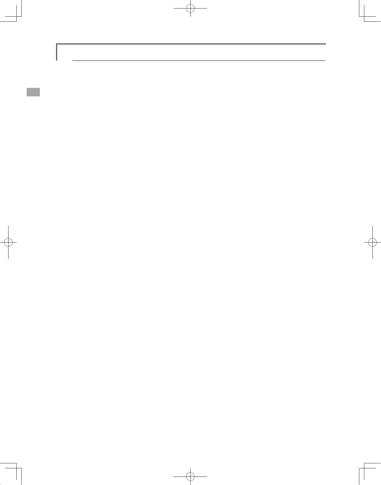
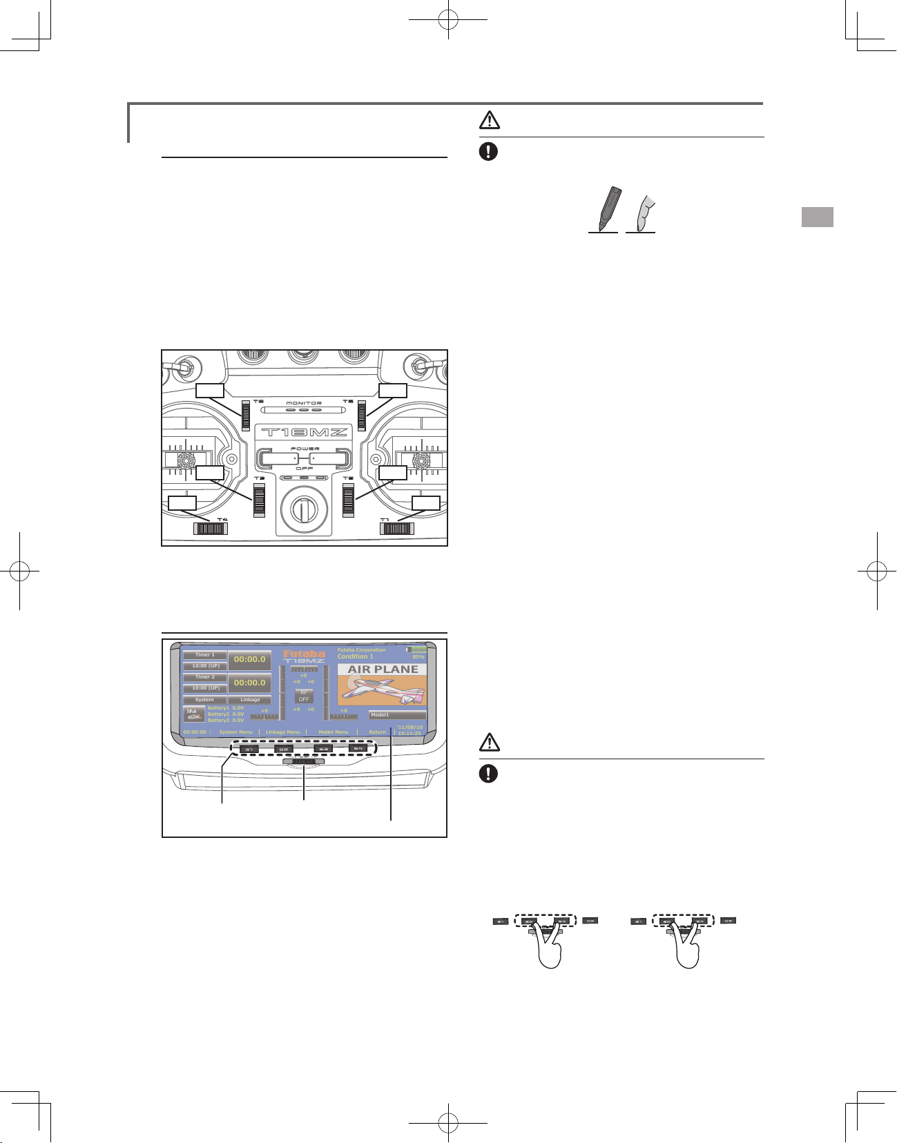
Transmitter controls
(LD,CD,RD)
●Switch Block
(SA,SB,SE,SF)
●Antenna
●Monitor LED
●Carrying Handle
●Volume
●Speaker
●Microphone
●Switch Block
(SC,SD,SG,SH)
●Slide
Lever
(LS,LST)
●Stick
(J3)
(J4)
●Digital
Trim
(T1-T6)
●Power
Switch
●Hook
●Direct Key
Cautions on handling antenna
(S1-S4)
●Rotary Key
●Slide Lever
(RST,RS)
●Stick
(J2)
(J1)
●LCD Display (Touch Panel)
<Before Use>
14
WARNING
Do not touch the antenna during operation.
*There is the danger of erroneous operation causing a
crash.
Do not carry the transmitter by the antenna.
*There is the danger that the antenna wire will break and
operation will become impossible.
Do not pull the antenna forcefully.
*There is the danger that the antenna wire will break and
operation will become impossible.
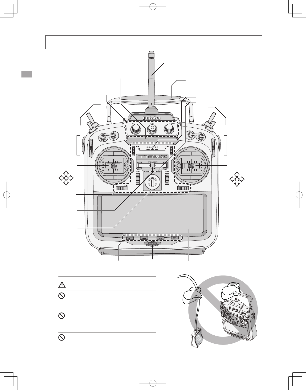
Page 15
•Rotating antenna
The antenna can be rotated 90 degrees and angled
90 degrees. Forcing the antenna further than this
can damage it. The antenna is not removable.
90°
LED monitor
The status of the transmitter is displayed by
changing the “MONITOR” section LED.
(LED Display)
▅FASSTest mode → Light Blue light
▅FASST mode → Green light
▅S-FHSS mode → yellow-green light
▅RF-OFF → Violet light
▅Starting → Red light
▅Trainer Student → Blue light
Switch reallocation
You can reallocate the toggle switches on the
shoulders of the transmitter, as you like.
90°
•Angle adjustment of the antenna
The antenna rotation and angle can be adjusted.
The antenna features weak radio waves in the
forward direction and strong radio waves in the
sideways directions. Adjust the antenna angle to
match your ying style.
Low power
High power High power
(Default settings)
• SA : 3 positions; Alternate; Short lever
• SB : 3 positions; Alternate; Long lever
• SC : 3 positions; Alternate; Long lever
• SD : 3 positions; Alternate; Short lever
• SE : 3 positions; Alternate; Short lever
• SF : 2 positions; Alternate; Long lever
• SG : 2 positions; Alternate; Short lever
• SH : 2 positions; Momentary; Long lever
*You can choose the Switch and the On/Off position in the
Switch Selection menu of your mix.
•When you change switches:
To relocate switches;
1. Make sure your transmitter is off, and use
the attached 2.5mm hexagonal wrench
(included) to turn the screw counterclockwise on the switch block and detach
the block. Remove the screw holding the
switch block. Pull up on the switch block to
remove it.
2. Disconnect the connectors of switches you
want to change.
<Before Use>
15
Page 16
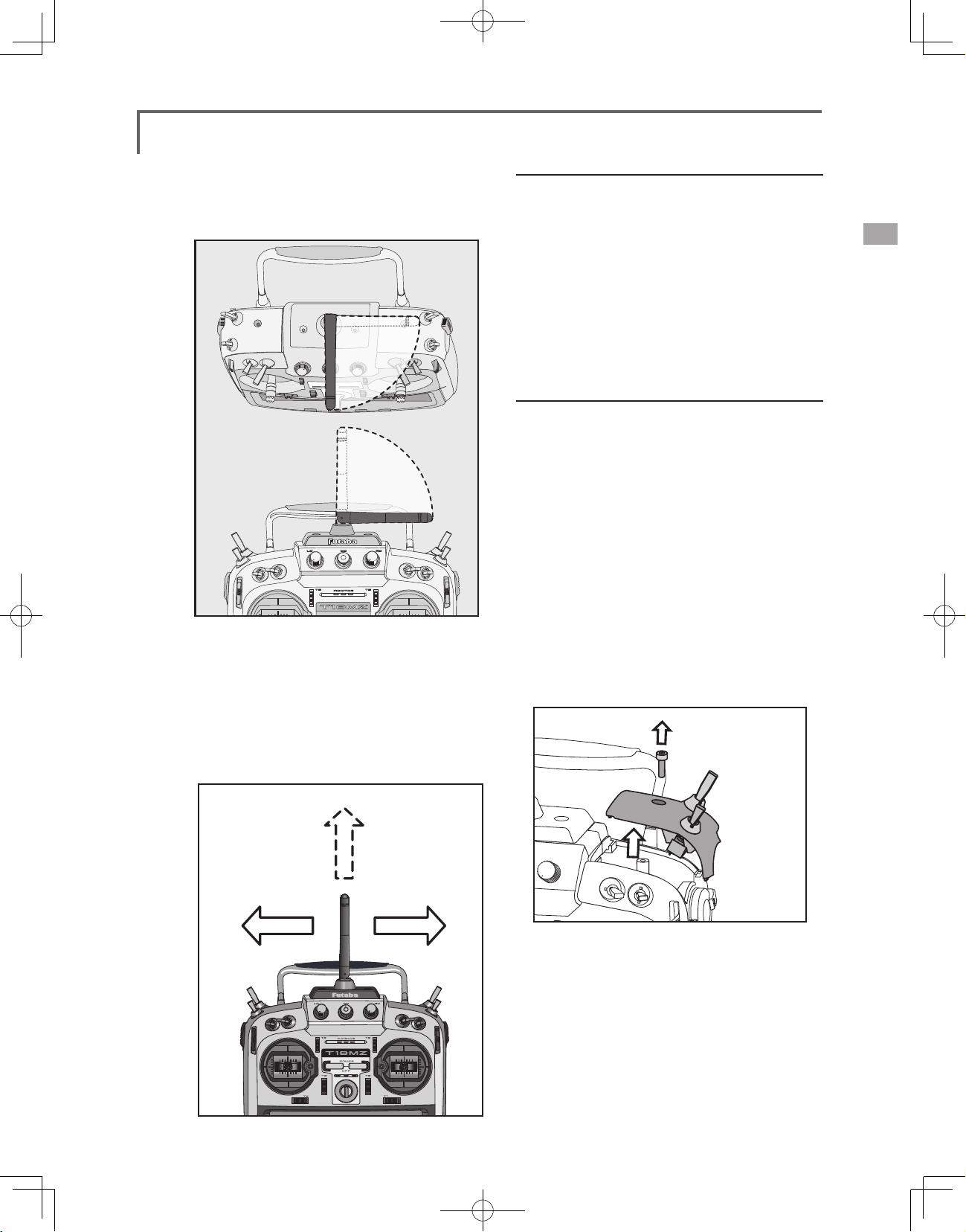
3. Use the attached jig (inside stylus) to turn the
Pushingdownoneither
theLDorRDvolumecontrol
willlockitin
thedown
position.
Pushingthevolumecontrol
againwillreleaseitsothatit
canadjusted.
face nuts counterclockwise, this will detach
the switches.
4. To re-attach, use the face nuts to attach
switches from other positions or optional
switches to the switch block.
5. Connect your connectors.
6. Insert the switch block so reconnect the
connectors that it ts correctly into the body
of the transmitter (as shown in the picture)
and use the hexagonal wrench to tighten
the screws.
Volume
Slide Lever
LeverLSbackandforth
movementlinkedoperation
LeverLSTindependentoperation
LST (Left), RST (right):
Outside levers
Volume LD, CD, and RD:
If you push the volume button in, it will be
locked in place. To release the volume button, push
it in lightly once more.
This volume is digital type (rotary encoder). This
volume works as both a volume and a push-switch.
*T18MZ beeps when the volume knob reaches center.
*You can check the volume position on the Dial Monitor
screen in the Linkage menu.
*You can use each setting screen of the mixing functions to
select volumes and dene the direction of its movement.
LS (Left), RS (right):
Inside levers: Each lever has two ends, one at the
front and the other at the back of the transmitter.
*It will beep when the lever is set to the center.
*You can check the lever position on the dial-monitor screen
in the linkage menu.
*You can select a slide lever and set the movement direction
on the setting screen of mixing functions.
16
<Before Use>
Page 17
Futaba Corporation
Condition 1
85%
Timer 1
10:00 (UP)
10:00 (UP)
00:00:00
Timer 2
System
System Menu
Battery1 0.0V
+0
+0 +0
+0
+0 +0
+0
Battery2 0.0V
Battery3 0.0V
Linkage
Linkage Menu Model Menu Return
ʻ11/08/10
15:11:25
Model1
00:00.0
00:00.0
RF
OFF
Caution
Digital trim
This transmitter is equipped with digital trims.
Each time you press a trim button, the trim position
moves one step. If you continue pressing it, the trim
position starts to move faster. In addition, when
the trim position returns to the center, the tone will
change. You can always monitor trim positions
graphics on the screen. To change the trim rate,
you must activate this through the function menu,
within the linkage menu. Touch the trim button and
you will access another screen which enables you
to change the trim percentages.
●T6 ●T5
●T3
●T2
●T4 ●T1
Note: The trim positions you have set will be stored in the
non-volatile memory and will remain there.
Touch Panel/ Rotary Key/ Direct Key
Touch softly the Touch Panel with the stylus
pen or your ngertips.
or
*Plastic lm is attached to the touch panel. Please be careful
so that you don't scratch the touch panel with anything hard
such as a metal object. Don't push the touch panel with
excessive force or drop anything on the panel.
*Although you may nd some air bubbles under the plastic
panel due to environmental changes such as temperature, it
is not a defect and will cause no problems.
Rotary key
In addition to touch panel, you can select items
by rotating the rotary keys to the left or to the right.
*There is a function which cannot be accessed by the Rotary
Key.
Direct key
You can directly call your favorite functions or
menu screens.
(The default setting at the factory)
S1: System menu
S2: Linkage menu
S3: Model menu
S4: Return
[How to change assignment of the direct key]
1. Open the screen you want to call. Then push
S1 and S4 keys simultaneously. (You will see
the direct key setting screen.)
2. Select the direct key.
3. The [Enter ]key is pressed.
4. The [Yes] key is pressed.
●Direct Key
(S1-S4)
●Rotary Key
●LCD Display (Touch Panel)
Touch panel, rotary keys and direct keys are used
for entering data.
Touch Panel
Touch the panel with your nger or the attached
stylus pen, which is also used as a toolbox, to enter
data.
Danger
The T18MZ's touch screen is very sensitive.
To avoid accidently activating it during a
ight, it is suggested that it be locked. Due to
the new sensitive type touch screen, if a neck
strap hook, servo extension, or even your hand
during a flight touches the screen, it could be
dangerous. Please use the touch panel lock for
added safety during ight.
●Direct Key
(S2-S3)
The touchpanellocked by
S2 and S3 pushed.
Locking the LCD touch screen.
* Maintain a touch-panel lock irrespective of ON/OFF of a
transmitter.
●Direct Key
(S2-S3)
The touchpanelunlocked by
S2and S3 pushed again.
<Before Use>
17
Page 18
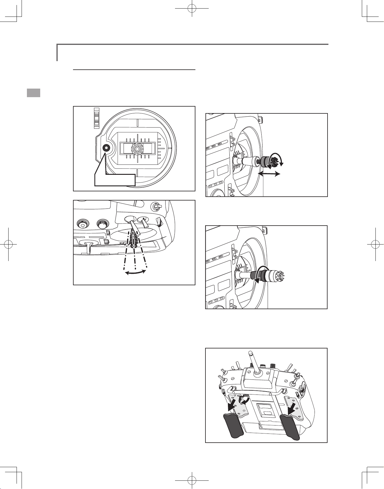
Stick Adjustment
Adjustment of the stick lever angle
You can make fine adjustments to the angle of
a stick lever either inwards or outwards from the
center stick position.
●Screw
[How to adjust the Stick length.]
1. Hold the lever head "B" and turn the lever
head "A" counter-clockwise, the lock will be
released.
2. Adjust the stick lever to the desired length by
turning lever head A.
. Securely lock the stick lever by holding
3
lever head A and turning lever head B
counterclockwise.
<Before Use>
18
Use the attached 1.5mm hexagonal wrench
(inside stylus) to turn the screw clockwise to adjust
the stick outwards, or counter-clockwise to tilt it
inward.
Note: Be careful not to turn the screw too far
counterclockwise as it could fall out.
Adjustment of the lever length
You can adjust the length of stick levers, as you
like. It is recommended to adjust the length of the
sticks in line with your hand size.
Adjustment of Stick Lever Tension
You can adjust the tension of stick-levers.
The rubber cover in the back is removed rst.
Page 19
●Retaining Force (J2)
(Mode 1/3)
●Stick
Tension
●Stick Tension(J2)
(Mode 2/4)
(J1)
●Stick Tension(J3)
(Mode 1/3)
●Retaining
Force (J3)
(Mode 2/4)
●Stick Tension(J4)
*This transmitter has two ratchet plates, one for airplane and
the other one for helicopter. If you tighten both screws, you
won't able to achieve the adjustment that you need because
of the overlap of those two adjustments.
*If you want to change the setting from airplane to helicopter
(or from helicopter to airplane), turn the ratchet screw
clockwise until the throttle stick moves freely. Then turn the
screw for the helicopter until you get the tension you like.
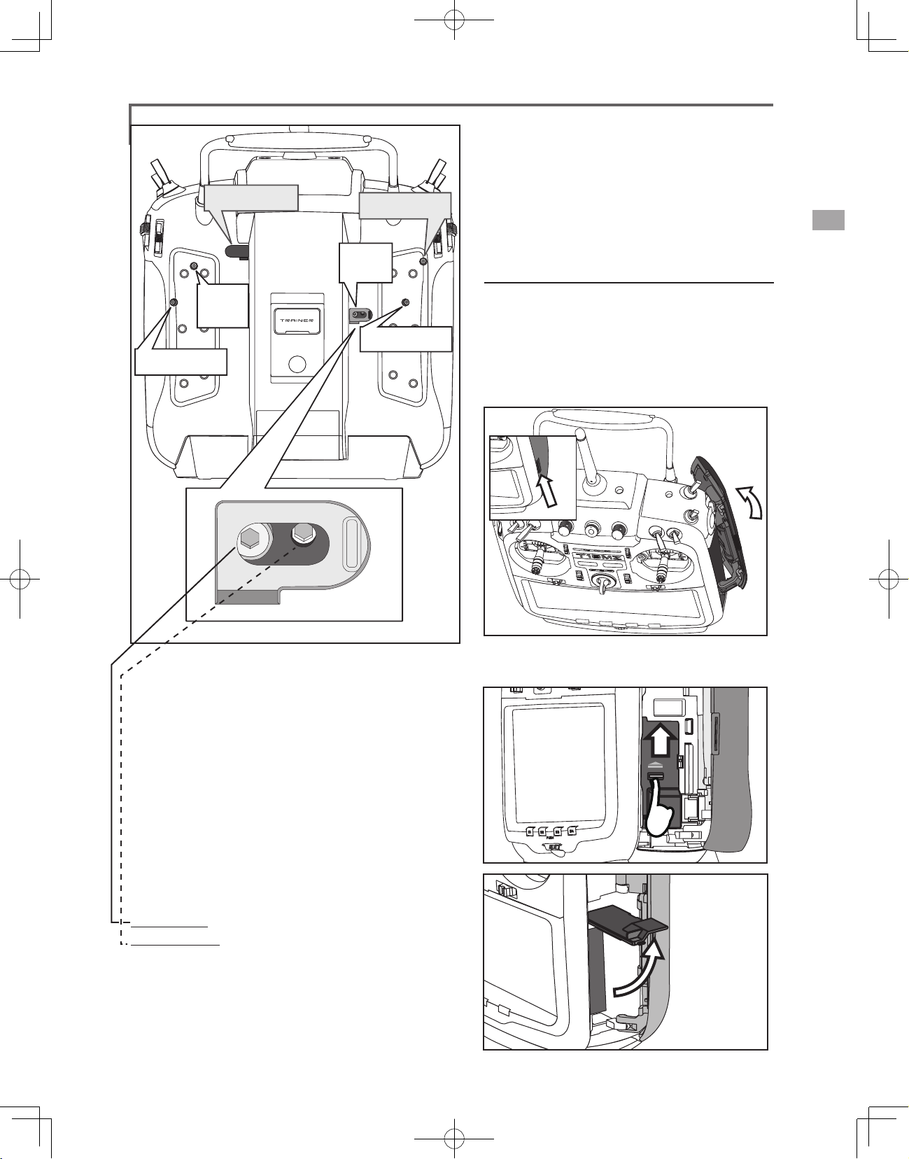
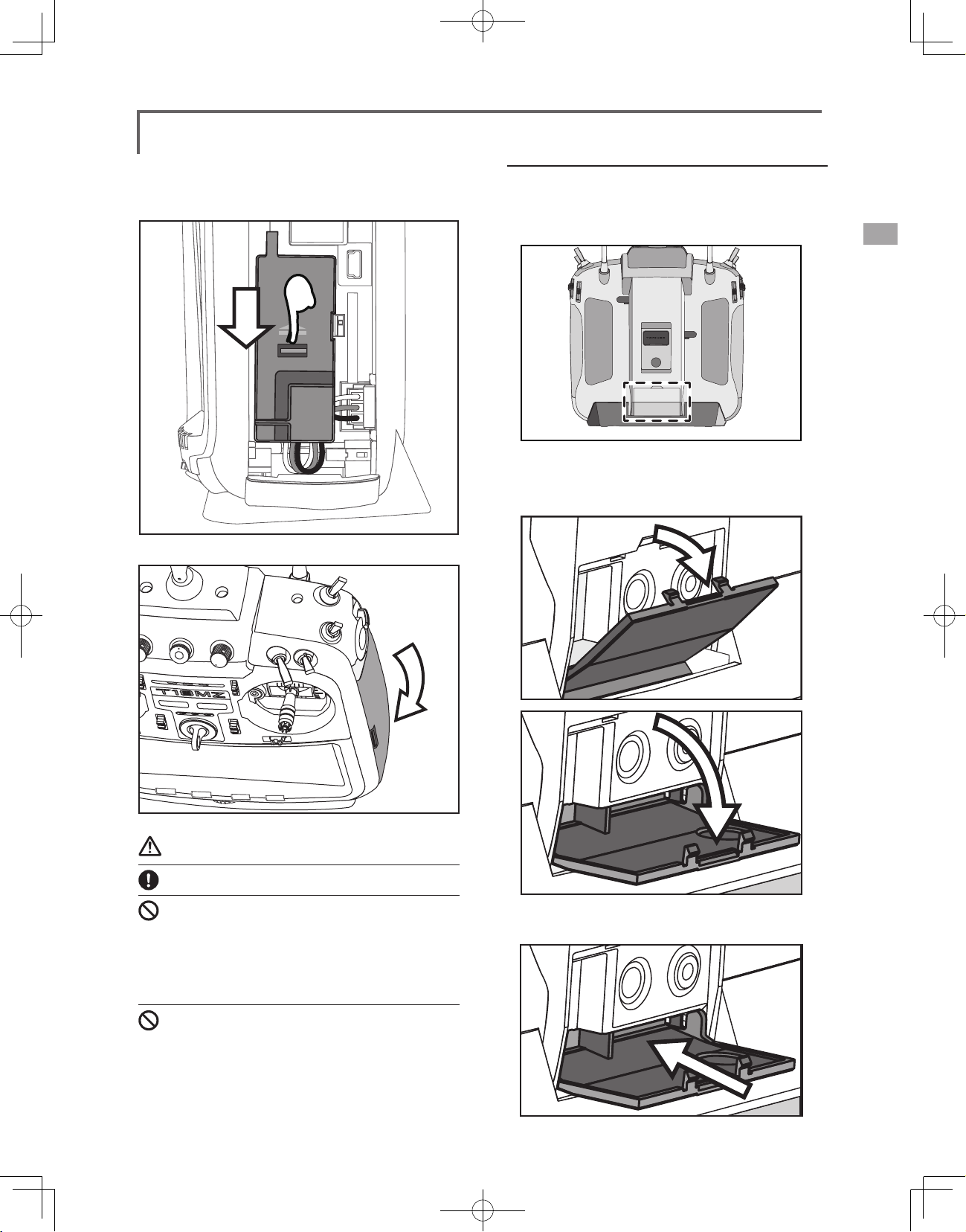
Battery exchange
Note: Detaching the battery while the power
is one can cause data you have recently edited to
be lost.
[How to remove battery LT2F3500XH]
1. Using the tabs at the side of the transmitter,
open the side door to the rear as shown in
the gure.
*In the Mode 1/3, arrangement of a screw is opposite.
[Adjustment of tension]
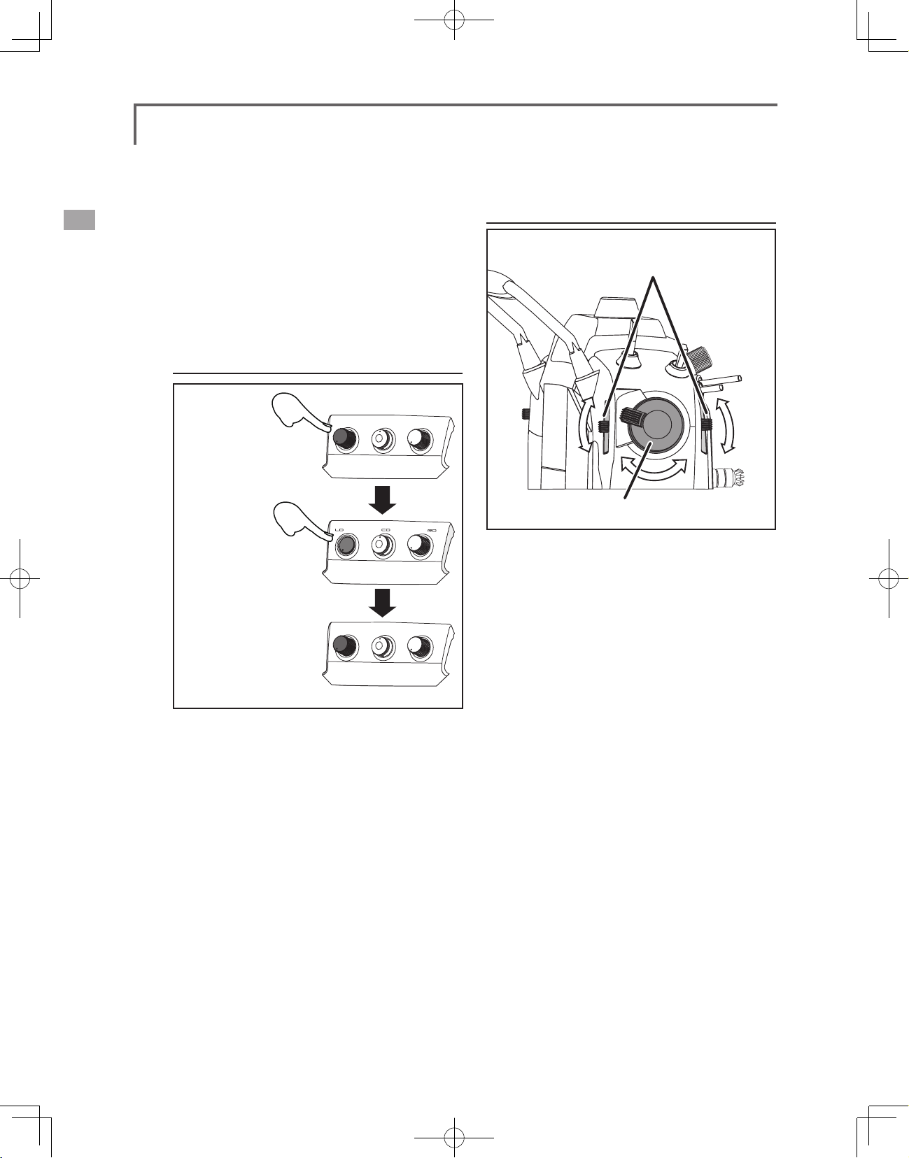
Adjustment of Throttle Stick (Ratchet System)
You can choose either airplane ratchet system or
helicopter-touch.
1. Open the dust protection cap on the back of the
transmitter that is covering the hole for throttle stick
adjustment.
2. Use the attached 1.5mm hexagonal wrench (inside
stylus) to turn the adjustment screw and set it as you
prefer. Turning the screw clockwise increases the
tension.
For airplanes: Adjust the screw on the left.
For helicopters: Adjust the screw on the right.
In changing the setting from airplane to helicopter (or
heli to airplane);
1. Turn the screw counter-clockwise until the throttle
stick moves freely, and turn the screw clockwise to
adjust it to the tension you prefer.
2.Open the battery cover inside the transmitter
by sliding it upward as shown in the gure.
<Before Use>
19
Page 20
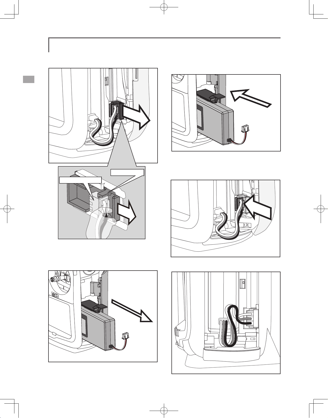
3. Pull up on the lip of the black "connector slider"
to remove the battery connector.
connector slider
Battery connector
[How to install battery LT2F3500XH]
1. Insert the battery into the transmitter.
2. Insert the battery with the battery connector
facing the direction shown in the gure. (Push
the battery housing, not the battery wiring. )
*Remove the connector by pulling up on
the lip of the slider, not the wiring.
4. Pull out the battery.
<Before Use>
20
. Arrange the battery wiring as shown in the
3
gure.
Page 21
Close the battery cover so that the wiring is
4.
not pinched and lock the cover by pushing
downward.
. Close the side door.
5
Back lid
The charging connector, earphone jack, and S.BUS
setting connector, charge LED are accessed by
opening the transmitter rear cover as shown in the
gure.
[How to open back lid.]
1. Open the transmitter rear cover as shown in
the gure.
Warning
Be careful to not drop the battery.
Never take out the battery from the T18MZ
transmitter while the LED monitor is blinking.
* Internal settings and memories can be destroyed.
* Do not use the transmitter if a “Backup Error” warning oc-
curs. Send it to the Futaba Service Center to be checked.
Don't pull battery wiring.
*When it short-circuits, there is danger of explosion ignition.
2. House the rear cover by pushing it into the
transmitter.
<Before Use>
21
Page 22
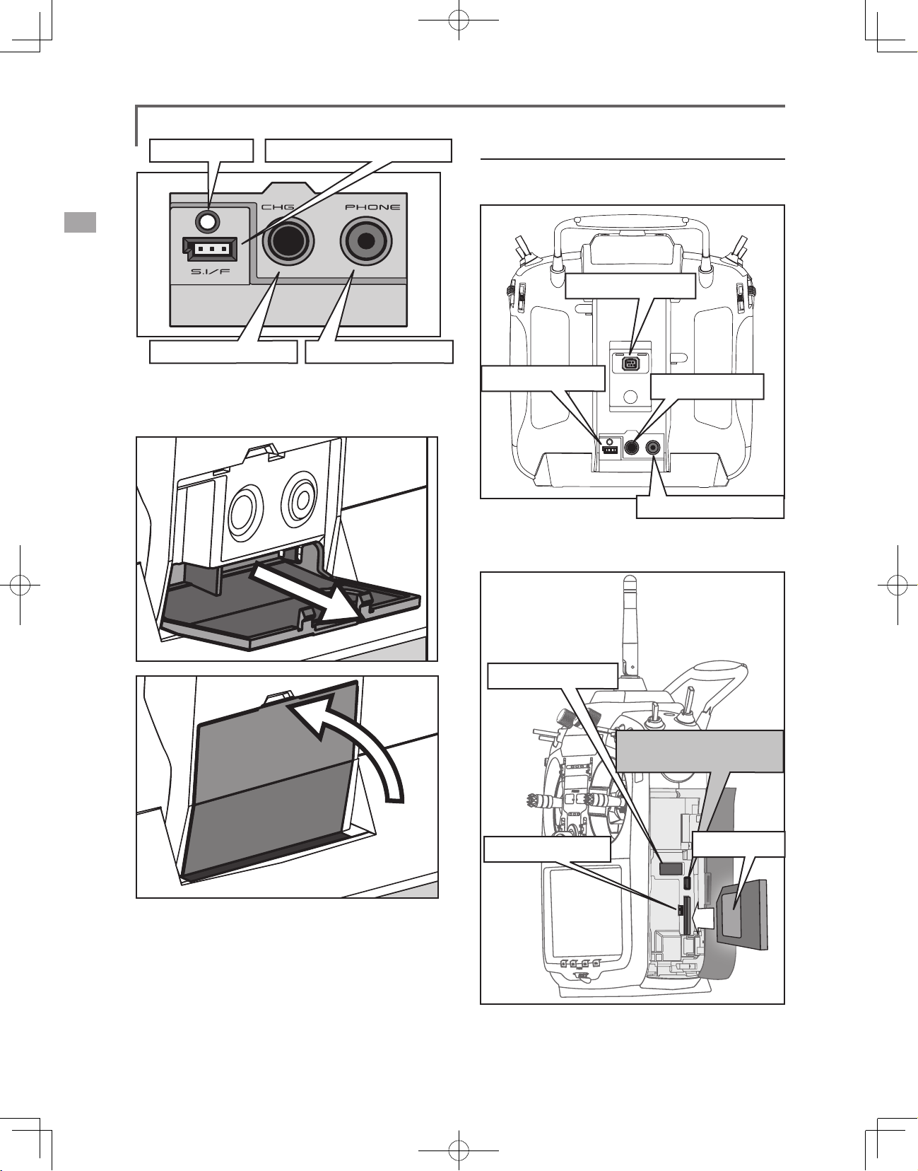
Charge LED
S.BUS setting connector
Connector/Plug
1. The back of transmitter.
Trainer Connector
Charge plug
3. When not using the connector, pull out and
close the rear cover.
.
Audio plug (PHONE)
S.BUS Connector
Charge Plug
Audio plug (PHONE)
2. Inside of transmitter of side cover
USB Connector
USB(mini-B) Connector
Unused
<Before Use>
22
Update Switch
SD Card
Page 23
SD Card (sold separately)
The SD card can store various files, such as
model data, music, sound files and pictures. Any
SD card on the market can be used with the
T18MZ. The card is locked when it is pushed in all
the way in. To remove the card, push in on the card
again, it will pop up allowing you to remove it.
Warning
Be sure to turn off the power to the transmitter
before inserting or removing the SD card.
As the SD card is a precision device, do not use
excessive force when inserting.
If model data generated by a new software
version transmitter is copied to an old software
version transmitter, the transmitter may
operate erroneously. Copy the model data after
updating the copy destination transmitter to the
new software version.
Read data from a PC
Saving music and image files edited by a PC
into the SD card, you can use those files on your
T18MZ transmitter. Equipment for reading and
writing SD cards are available at most electronics
stores.
Stored data
The life of the SD card is limited due to the use
of Flash memory. If you have a problem saving or
reading data such as picture data after a long period
of use you may need to purchase a new SD card.
*We are not responsible for, and cannot compensate for any
failure to the data stored in the memory card for any reason.
Be sure to keep a backup of your models and data in your
SD card.
*No necessity for backup; T18MZ transmitters and SD
cards are using nonvolatile memory devices so that the data
stored in those will not be destroyed even without a backup
battery. The clock for the transmitter depends on the Lithium
battery.
Update Switch
When using an SD card to update the T18MZ
software, set this switch to the up position. Then
input the software to be updated to the SD card
from the Futaba importers homepage and update
the software in accordance with the updating
procedure.
USB port
The following functions can be used with USB
connector.
• USB Mouse
When a mouse is connected, a cursor will
appear on the screen and the mouse can
be used instead of the touch panel.
• USB Keybord
When a keyboard is connected, the model
name and other data can be input by
keyboard.
• USB Memory
All model data, etc. can be saved to an
optional USB Memory stick.
Connector for trainer function (TRAINER)
When you use trainer function, connect the
optional trainer cable between the transmitters for
teacher and student.
*You can set the trainer function on the Trainer Function
screen in the system menu
Connector for DSC function (DSC)
You can operate the transmitter without
transmitting radio waves by connecting the
transmitter and the receiver to the DSC cable.
*Please refer to the section "Connection between Receiver/
Servo"
S.BUS connector (S.I/F)
When setting an S.BUS servo and telemetry
sensor, connect them both here.
(Supply power by 3-way hub or 2-way cord.)
Audio plug (PHONE)
Connecting a stereo headphone to this plug, you
can enjoy music les stored in the SD card.
Connector for battery charger (CHG)
You cannot use the charger that was included
with the transmitter, without using the AC adapter
that comes with this.
Danger
Do not connect any other chargers. The charger
for the receiver battery cannot be used for the
transmitter.
USB port (mini-B)
*This is for factory use only.
<Before Use>
23
Page 24
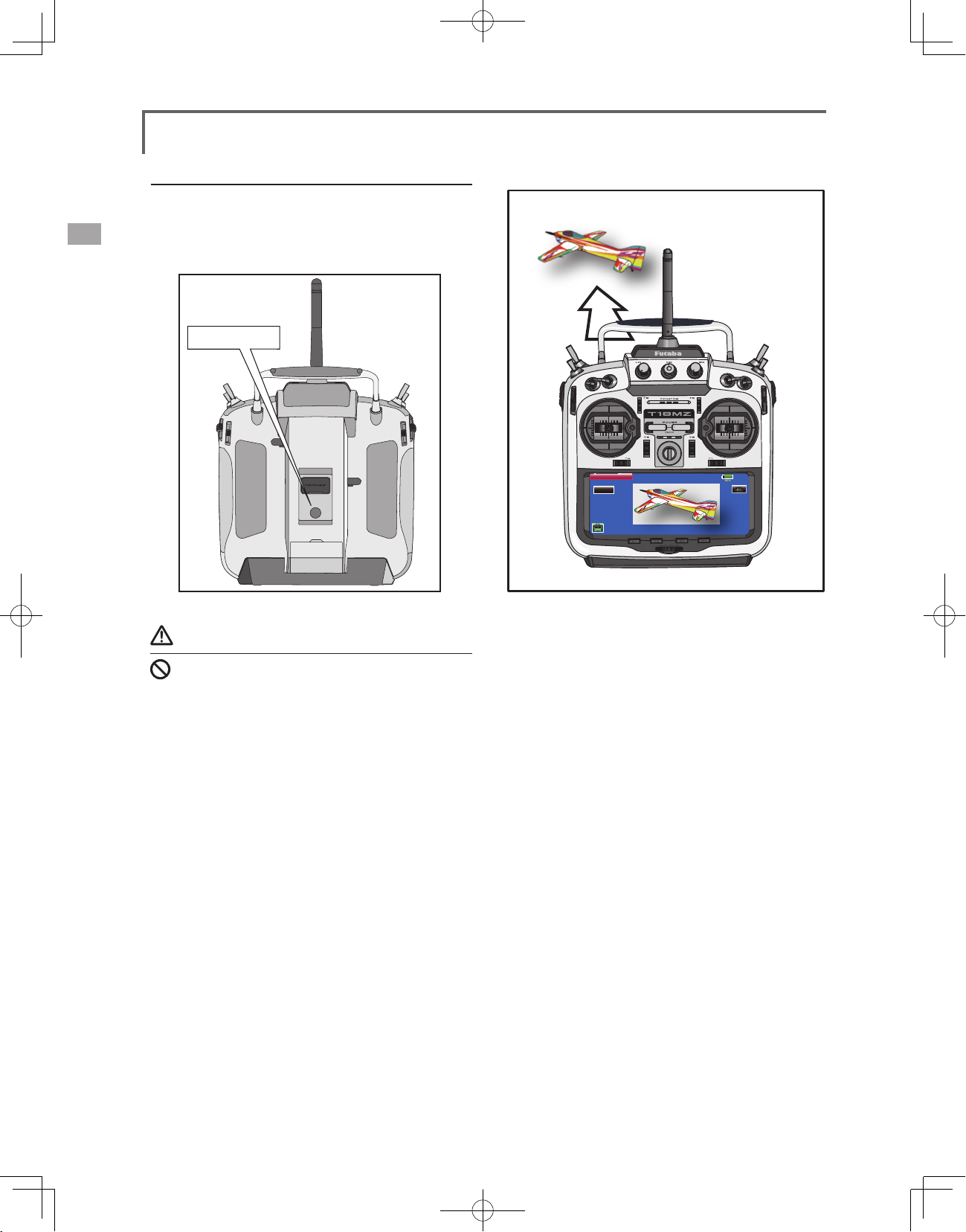
Camera function
This transmitter has a digital camera function.
A picture of your favorite model and other pictures
(0.03M megapixels) can be allocated to transmitter
model data.
Camera
Warning
Do not use the camera function during ight and
when starting the engine.
*It is dangerous to look away from or have your model out of
your line of sight while ying.
Model 1
Thumbnail
Save to...
Camera
85%
<Before Use>
24
Page 25
Receiver nomenclature
Before using the receiver, be sure to read the
precautions listed in the following pages.
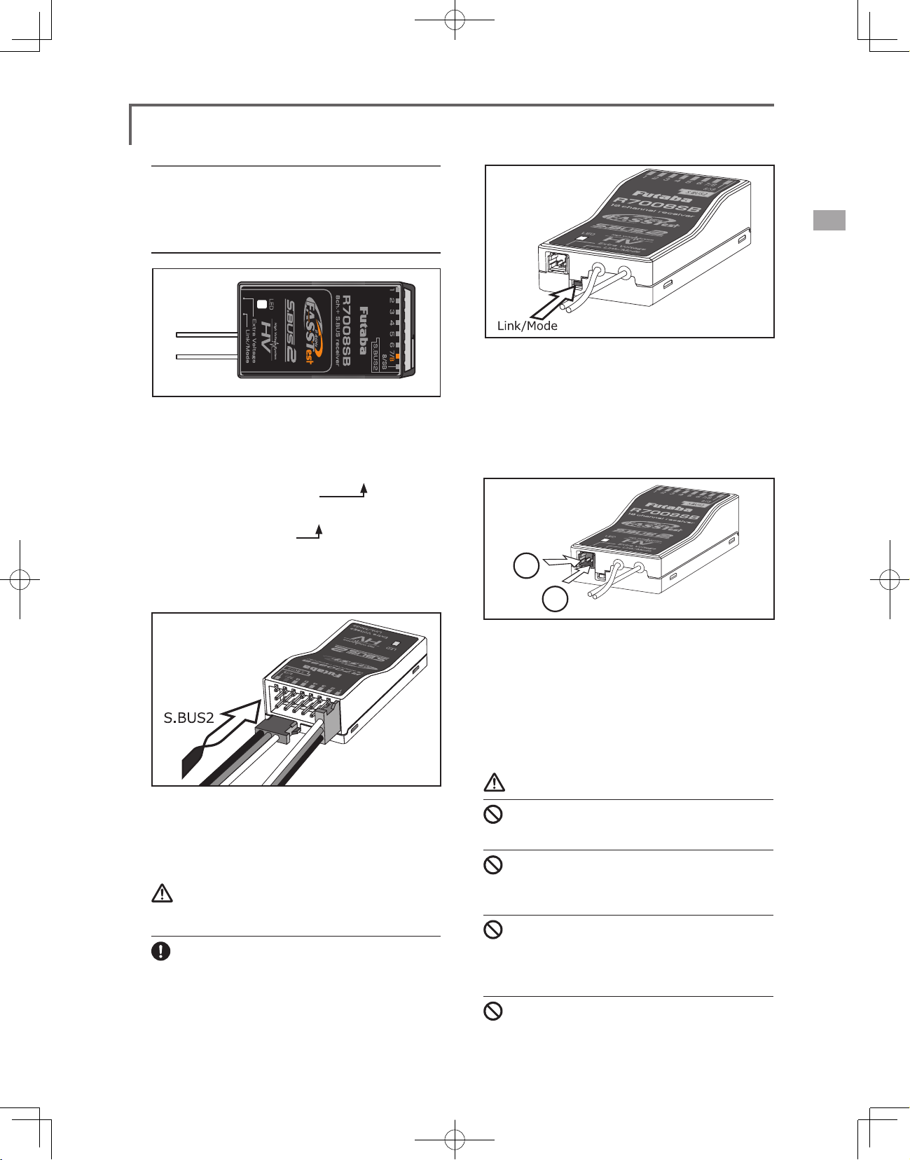
Receiver R7008SB
Connector
"1 through 6": outputs for the channels 1 through 6
"7/B": outputs of 7 channels and power.
"8/SB": outputs of 8 channels or S.BUS port.
[S.BUS Sevo S.BUS Gyro ]
"S.BUS2": outputs of S.BUS2 port.
[Telemetry Sensor ]
*When using 9 or more channels, use an S.Bus
function or use a second R7008SB and link both to
your transmitter.
Link/Mode Switch
Use the small plastic screw driver that was
included with your receiver.
The Link/Mode Switch is also used for the CH
mode selection.
(The button is not used to link the transmitter
and receiver together. )
+
−
Connector insertion
Firmly insert the connector in the direction
shown in the gure. Insert the S.BUS2 by turning it
90 degrees.
Warning
S.BUS2 connectors
Don't connect an S.BUS servo / gyro to BUS2
connector.
LED Monitor
This monitor is used to check the CH mode of
the receiver.
Extra Voltage Connector
Use this connector when using a voltage
telemetry device to send the battery voltage (DC0 ~
70V) from the receiver to the transmitter.
Please use an option is External voltage input
cable. Wire in an extra connector to you drive
batteries that mates with the extra voltage connector.
Danger
Don't touch wiring.
* There is a danger of receiving an electric shock.
Do not short-circuit the battery terminals.
* A short circuit across the battery terminals may cause
abnormal heating, re and burns.
Please double check your polarity ( + and -)
when hooking up your connectors.
* If + and - of wiring are mistaken, it will damage, ignite and
explode.
Don’t connection to Extra Voltage before
turning on a receiver power supply.
<Before Use>
25
Page 26
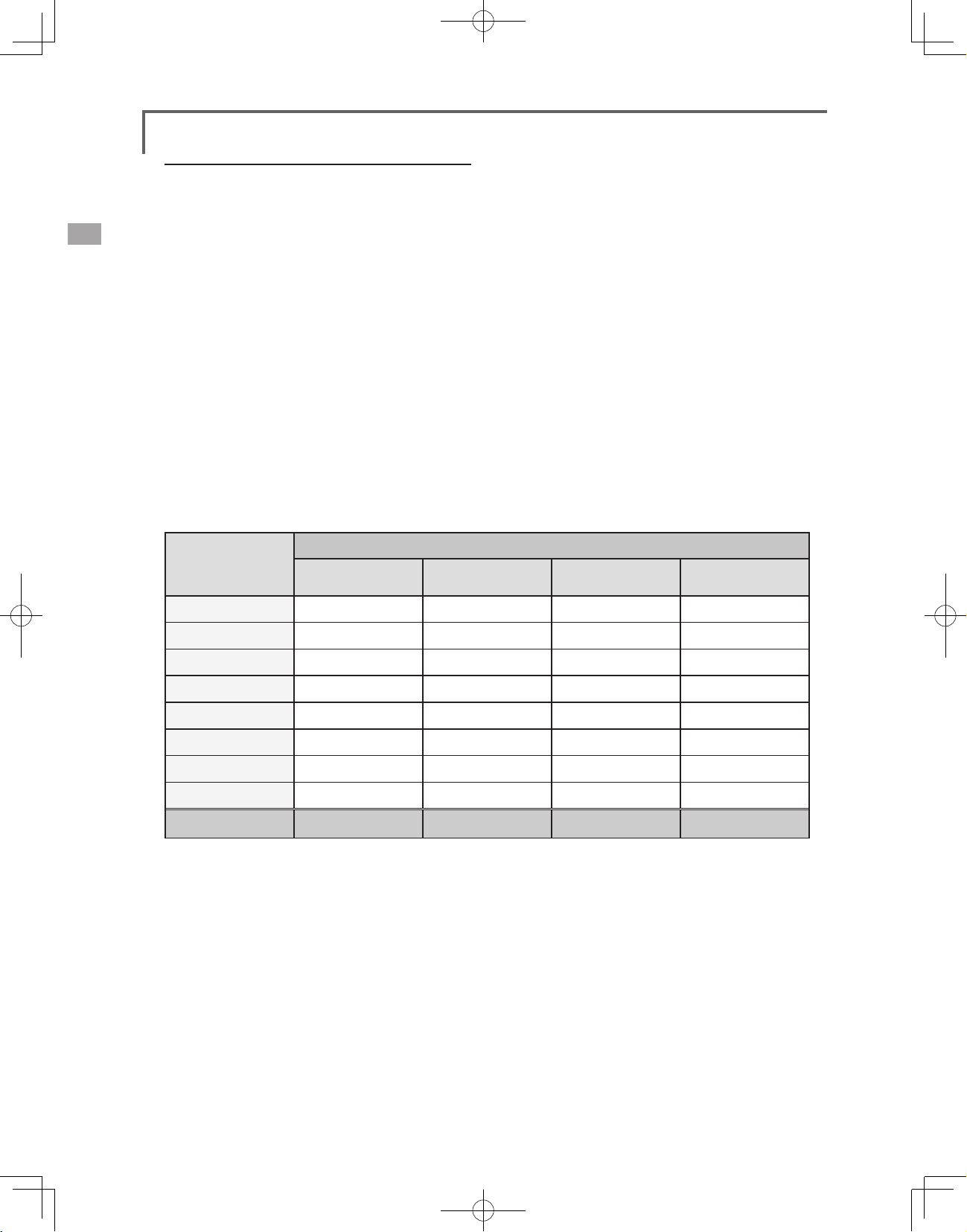
R7008SB CH Mode
The R7008SB receiver is a very versatile unit.
It has 8 PWM outputs, S.Bus and S.Bus2 outputs.
Additionally the PWM outputs can be changed
from channels 1-8 to channels 9-16. If you only
desire to use it as an 8 channel receiver (without
S.Bus), it can be used without any setting changes.
The T18MZ has the ability to link to two
R7008SB receivers. One of them outputting
channels 1-8 and the other outputting channels
9-16 giving you 16 PWM channels. Instructions
for this conguration and S.Bus operation follow.
R7008SB CH MODE TABLE
Receiver connector
1 1 1 9 9
Mode A
1 ~ 8CH
Mode B
1 ~ 7CH
[How to change the R7008SB Channel mode.]
1. Press and hold down the Link/Mode button
on the R7008SB receiver.
2. Turn the receiver on while holding down the
Link/Mode button. when the LED begins to
blink green/red the button may be released.
3. The LED should now be blinking red in one of
the patterns described by the chart below.
4. Each press of the Mode/Link button
advances the receiver to the next mode.
5. When you reach the mode that you wish to
operate in, press and hold the Mode/Link
button for more than 2 seconds.
6. Once locked into the correct mode the LED
will change to a solid color.
7. Please cycle the receiver(s) power off and
back on again after changing the Channel
Mode.
Setting channel
Mode C
9 ~ 16CH
Mode D
9 ~ 15CH
2 2 2 10 10
3 3 3 11 11
4 4 4 12 12
5 5 5 13 13
6 6 6 14 14
7/B 7 7 15 15
8/SB 8 S.BUS 16 S.BUS
Red LED blink 1time 2time 3time 4time
<Before Use>
26
Page 27
Servo(Option)・Toolbox
Servo(Option)
Purchase servos appropriate for their intended use.
*Analog servos may not be used when operating in the
FASSTest 12CH mode.
When operating in the FASSTest12Ch mode use digital servos,
this includes all brushless and S.Bus servos.
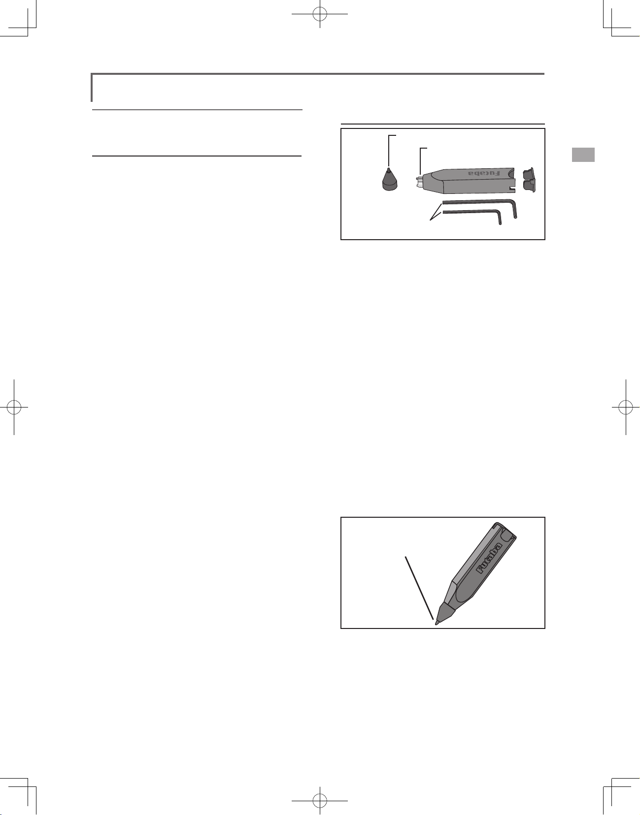
Toolbox
●Rubber Cap
●Tool for removing
decoration nuts
●Hex. Wrench (1.5mm and 2.5mm)
A special toolbox is included with your T18MZ.
This allows you to make off of the mechanical
adjustments that may be needed.
Hexagonal wrench (1.5mm and 2.5mm)
These wrenches are for adjustment of sticks,
replacement of the switches.
Tool for removing switch nuts.
This is used when changing or replacing
switches.
Stylus pen
A rubber cap is attached to the stylus pen/
toolbox. You may use this stylus with rubber cap
when operating the touch panel. The stylus allows
more precise operation than ngers without fear of
damaging the panels surface.
●You may use this tool
as a stylus pen.
<Before Use>
27
Page 28
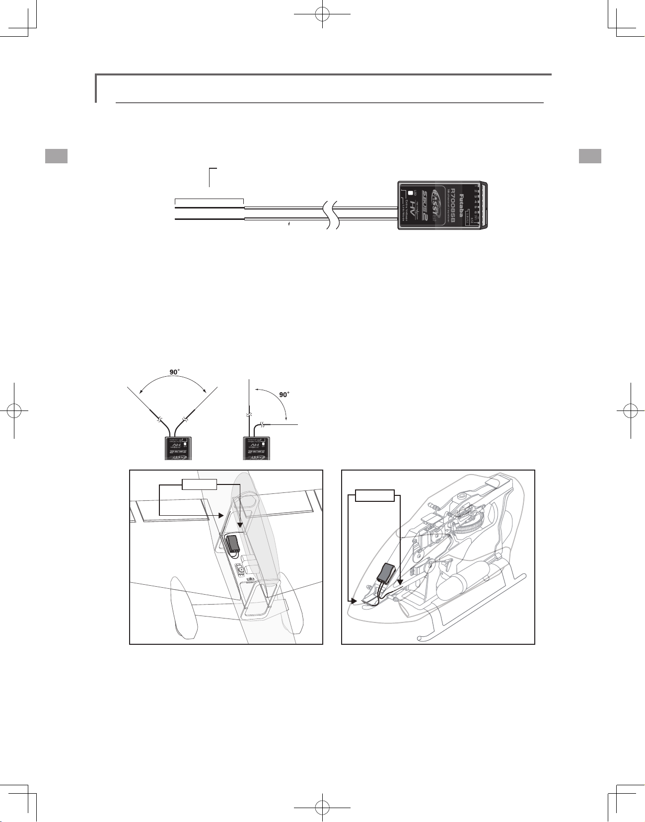
Receiver's Antenna Installation
The R7008SB has two antennas. In order to maximize signal reception and promote safe modeling
Futaba has adopted a diversity antenna system. This allows the receiver to obtain RF signals on both
antennas and y problem-free.
*Must be kept as straight as possible.
Antenna
Coaxial cable
To obtain the best results of the diversity
function, please refer to the following instructions:
1. The two antennas must be kept as straight as
possible. Otherwise it will reduce the effective
range.
2. The two antennas should be placed at 90
degrees to each other.
Antenna
R7008SB Receiver
This is not a critical figure, but the most
important thing is to keep the antennas
away from each other as much as possible.
Larger models can have large metal objects
that can attenuate the RF signal. In this case
the antennas should be placed at both
sides of the model. Then the best RF signal
condition is obtained at any ying attitude.
3. The antennas must be kept away from
conductive materials, such as metal, carbon
and fuel tank by at least a half inch. The
coaxial part of the antennas does not need
to follow these guidelines, but do not bend it
in a tight radius.
4. Keep the antennas away from the motor,
ESC, and other noise sources as much as
possible.
Antenna
<Before Use>
28
*The two antennas should be placed at 90 degrees to each other.
*The Illustration demonstrates how the antenna should be placed.
*Receiver Vibration and Waterproong: The receiver contains precision electronic parts. Be sure
to avoid vibration, shock, and temperature extremes. For protection, wrap the receiver in foam
rubber or other vibration-absorbing materials. It is also a good idea to waterproof the receiver
by placing it in a plastic bag and securing the open end of the bag with a rubber band before
wrapping it with foam rubber. If you accidentally get moisture or fuel inside the receiver, you
may experience intermittent operation or a crash. If in doubt, return the receiver to our service
center for service.
Page 29
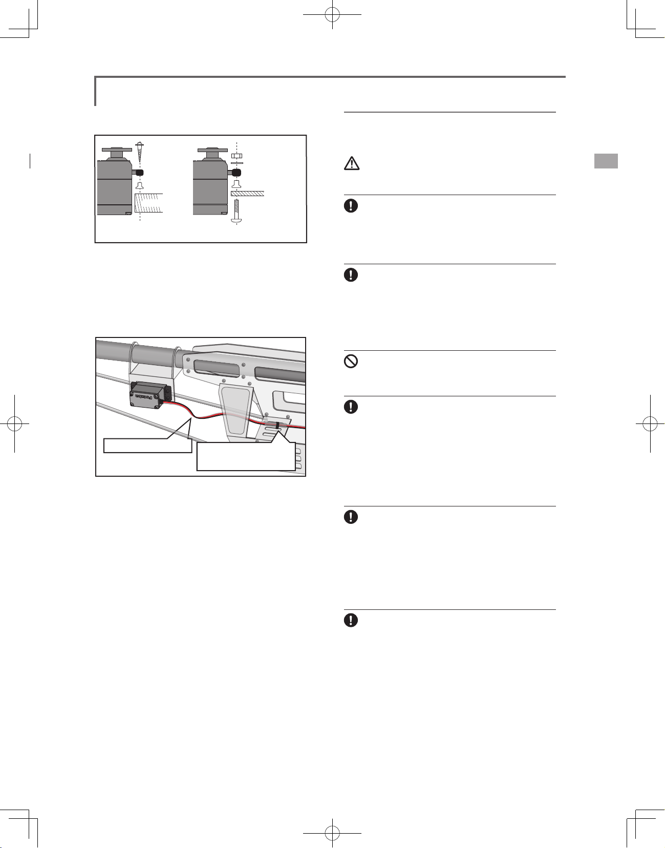
Rubber
grommet
Brass eyelet
Wood screw
Servo mount
2.3-2.6mm nut
washer
Rubber
grommet
Brass eyelet
Servo mount
2.3-2.6mm screw
(Helicopter)(Airplane/Glider)
Mounting the Servo
Servo lead wires
To prevent the servo lead cable from being
broken by vibration during flight, provide a
little slack in the cable and fasten it at suitable
points. Periodically check the cable during daily
maintenance.
Margin in the lead wire.
Fasten about 5-10cm
from the servo outlet so
that the lead wire is neat.
Safety precautions when you install
receiver and servos
Warning
Connecting connectors
Be sure to insert the connector until it stops at
the deepest point.
How to protect the receiver from vibration and
water
Wrap the receiver with something soft such
as foam rubber to avoid vibration. If there is
a chance of getting wet, put the receiver in a
waterproof bag or balloon to avoid water.
Receiver's antenna
Never cut the receiver's antenna. Do not bind
the receiver's antenna with the cables for
servos.
Locate the receiver's antenna as far as possible
from metals or carbon fiber components such
as frames, cables, etc.
*Cutting or binding the receiver's antenna will reduce the ra-
dio reception sensitivity and range, and may cause a crash.
Mounting the power switch
When mounting a power switch to an airframe,
make a rectangular hole that is a little larger than
the total stroke of the switch so that you can turn
the switch ON/OFF without binding.
Avoid mounting the switch where it can be
covered by engine oil and dust. In general, it is
recommended to mount the power switch on the
side of the fuselage that is opposite the mufer.
Servo throw
Adjust your system so that pushrods will not
bind or sag when operating the servos to the
full extent.
*If excessive force is continuously applied to a servo, the
servo could be damaged due to force on the gear train and/
or power consumption causing rapid battery drain.
Mounting servos
Use a vibration-proof rubber (such as rubber
grommet) under a servo when mounting the
servo on a servo mount. And be sure that the
servo cases do not touch directly to the metal
parts such as servo mount.
*If the servo case contacts the airframe directly, vibration
will travel to and possibly damage the servo.
<Before Use>
29
Page 30
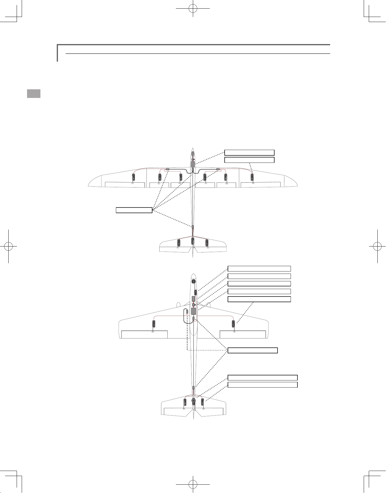
S.BUS Installation
This set uses the S.BUS system. The wiring is as simplified and clean mounting as possible, even with
models that use a large number of servos. In addition, the wings can be quickly installed to the fuselage
without any erroneous wiring by the use of only one simple wire, even when there are a large number of servos
used.
●When using S.BUS, special settings and mixes in your transmitter may be unnecessary.
●The S.BUS servos and S.BUS gyros memorize the number of channels themselves. (Settable with the
T18MZ)
●The S.BUS system and conventional system (receiver conventional CH used) can be mixed.
S.BUS GliderUsageexample
HUB×4(Optional)
S.BUSAerobaticAirplaneUsage
example
Receiver:R7008SB
Servo:S3171SB×9(Optional)
Throttleservo:S9070SB(Optional)
Battery:FR2F1800(Optional)
Switch:HSW-L
Receiver:R7008SB
Aileronservo:BLS174HV×2(Optional)
<Before Use>
30
HAB×3(Optional)
RudderServo:BLS175HV×1(Optional)
Elevatorservo:BLS171HV×2(Optional)
Page 31

S.BUS Wiring example
Receiver
S.BUS
Port
(8/SB)
GY520
Extension
cord
Battery
Switch
Terminal box
●S.BUSServo
Since the channel number is memorized by
the S.BUS itself, any connector can be used.
When the SBD-1 (sold separately) is used,
ordinary servos can be used with the
S.BUS system.
Terminal box
●
Four connectors can be inserted
HUB
S.BUS Servo
HUB HUB
S.BUS Servo
HUB
HUB
(Another power supply)
HUB
●Whenseparatepowersupplyused
When a large number of servos are used or
when high current servos are used, the servos
Battery
can be driven by a separate power supply by
using a separate Power Supply 3-way Hub.
Warning
Power supply
Please make sure that you use a battery
that can deliver enough capacity for
the number and kind of servos used.
Alkaline batteries cannot be used.
Green
Orange
HUB
Three connectors can be
inserted.
HUB
(Another power supply)
Used when using a separate
power supply battery.
<Before Use>
31
Page 32

S.BUS2 System
Using the S.Bus2 port an impressive array of telemetry sensors may be utilized.
S.BUS2 TABLE
Receiver connector
S.BUS Servo
S.BUS Gyro
telemetry sensor
S.BUS ○ ×
S.BUS2 × (※) ○
(※)
Don't connect S.BUS Servo,
S.BUS Gyro to BUS2 connector.
S.BUS device setting
S.BUS servos or a telemetry sensor can be connected directly to the T18MZ. Channel setting and other data
can be entered for the S.BUS servos or sensors.
1. Connect the S.BUS device and battery you
want to set with a 3-way hub or 2-way cord
as shown in the gure.
2. Turn on the transmitter power.
3. Call the setup screen.
Servo: System Menu → S.BUS Servo
Sensor: Linkage Menu → Sensor
3-way hub
or 2-way
T18MZ
4. Perform setting in accordance with each
screen.
5. This sets the channel and other data for each
S.BUS servo, or telemetry device to be used
with the S.BUS device or receiver.
<Before Use>
32
S.BUS device
(S.BUS Servo)
(telemetry sensor)
Receivers
Battery
Page 33

Telemetry System
The R7008SB receiver features bi-directional communication with a FASSTest Futaba transmitter using the
S.Bus2 port. Using the S.Bus2 port an impressive array of telemetry sensors may be utilized. It also includes
both standard PWM output ports and S.Bus output ports.
*Telemetry is available only in the FASSTest 18CH mode. (12CH mode displays only Receiver battery voltage
and Extra battery voltage.)
*The telemetry function requires the corresponding receiver (R7008SB).
* Telemetry display only T18MZ ID of R7008SB was remembered to be.
●Telemetrysensor(soldseparately)
Signal
S.BUS2
Connector
Info
Info
T18MZ
Receiver
Info
voltage
Switch
Your aircrafts data can be checked in the
transmitter by connecting various telemetry
sensors to the S.BUS2 connector of the
receiver.
Drivebatteryvoltageis
displayedatthetransmitter.
Batteryvoltageis
displayedatthetransmitter.
Temperature
Info
HUB
Sensor
RPM
Sensor
Altitude
Sensor
Slot1
Slot2
Slot3
Terminal box
●SlotNo.
Servos are classified by channel, but sensors
are classified by “slot” . Since the initial slot
No. of the T18MZ is preset at each sensor,
the sensors can be used as is by connecting
them. There are 1~31 slots.
Info
Info
HUB
HUB
Altitude
Sensor
Altitude
Sensor
Sensor
Sensor
S.BUS2 Tool
<Before Use>
Slot4
Slot5
Slot6
Slot7
Slot8
33
Page 34

BASIC OPERATION
Battery Charging
Before charging batteries, read the "Cautions for
handling battery and battery charger" in the section
"For your safety".
Charging the transmitter LT2F3500XH lithiumpolymer battery
Danger
The LT2F3500XH lithium-polymer battery is
for the T18MZ transmitter only. Do not use it
with other devices.
Always use the accessory AC adapter to charge
the battery.
The charging circuit is built into the T18MZ.
[Method of charging battery]
AC100V
Chargelamp
T18MZ
of the battery.
*If the battery is improperly installed or is faulty, the
transmitter monitor will not light and the battery will not
charge.
How to charge the Li-Fe battery
FR2F1800(Option) for the receiver
Use the battery charger that is included in the set.
[Method of charging battery]
●The connector of the battery is
connected with "2S" side of
AC100V
1. Connect the power cable of the charger to
the wall socket (AC outlet).
2. Connect the connector to the Li-Fe battery.
*Conrm that the charging indicator, red LED lights.
3. Remove the battery after the LED light turns
green.
*After completing the charge remove the battery from the
charger and remove the charger from the wall outlet.
the charger.
Charger LBC-4E5
LBC-4E5
Balance CHARGER
Red on, green off : Charging
Green on, red off : Charging Full
Intelligent LiFePO4 for 2S/3S Cells
MODEL :
3S2S
Red flash : Output short-circuit or wrong polarity
(2S sids)
1. Turn off the transmitter power.
2. Connect the power plug of the AC adapter
to an 110V outlet.
*Don't connect AC plug to the T18MZ without connecting
with a 110V outlet.
3. Open the back lid of the transmitter and
insert the plug of the AC adapter into the
CHG port.
4. The charging monitor of the transmitter lights
red.
*The LCD screen will come on for several seconds and then
go off. It may take several seconds for charging to start after
the AC adapter is connected.
5. When the battery is fully charged the
transmitter monitor will light green. Remove
the charge plug and AC adaptor.
*After using the AC adapter always disconnect the power
cord from the AC outlet.
*The time to charge a completely discharged battery pack
is approximately 2 hours 30 minutes. However, the actual
charging time may vary depending on temperature and state
Warning
The transmitter battery cannot be charged with
the receiver charger. Conversely the receiver
battery cannot be charged with the transmitter
charger.
<Basic Operation>
34
Page 35

How to turn ON/OFF the power of the
transmitter
Windows® CE is installed as a built-in operating
system in the T18MZ transmitter. Compared to the
conventional system, the T18MZ takes extra time
for internal processing when it is turned on/off.
The right switch is
pushed.
When turning on the power of the transmitter
1. Place the throttle stick below 1/3 closed.
2. Turn on the power switch.
*After initialization of the transmitter is complete, the LED
monitor turns Purple.
*If your throttle stick is not at 1/3 closed or fully closed, a
warning will sound. If you move the throttle to 1/3 closed
or fully closed, the warning will stop and will become a
"Transmit ?" screen.
*If you push the button "NO", then the transmitter will not
emit radio waves.
*If you push the button "Yes", then the transmitter will emit
radio waves..
*If a battery is removed and it re-connects, please switch on a
power supply, after 3 seconds or more pass.
Start-up time;
The time required to initialize the internal circuit
of the transmitter varies between the previous time
you turned the power off and then restarted the
transmitter. There are two “start up” modes for your
transmitter, see below:
Cold start;
If you turn on the transmitter more than four
hours after you last turned it off, the mode is “Cold
start”. “Cold start” is normal for the first initial
power up of the day. It will take about 30 seconds
to be ready for use, as it takes time to initialize the
internal circuit of the transmitter.
Hot start;
If you turn on the transmitter less than four hours
after you last turned it off, the mode is “Hot start”.
Since initialization has been partly completed, the
transmitter will be ready to use in several seconds.
“Hot start” takes place usually at a second ight or
later ight in the day.
Warning
Once you turn on the power, never shut off the
power switch until the power becomes stable (or
until the rst screen shows up). If you turn off
the power switch while the transmitter is going
through the initialization process, the data could
be damaged. Note: The start-up time may be a
little bit slower when the SD card is installed
compared to when the card is not.
How to stop the transmitter
Turn off the power switch of the transmitter. The
internal circuit of the transmitter starts the shut
down process including saving the set-up data.
It will turn off by
pushing both
pieces
simultaneously.
or
It will turn it off by
pushing one side
for a length of
time.
Once you turn off the power, never operate the
power switch until the power shutdown process
is fully completed. If you turn on the power
switch again while the transmitter is still in the
process of power shutdown, the data could be
damaged.
As the internal circuit of the transmitter
stays on the standby mode for 4 hours after turning
<Basic Operation>
35
Page 36

off the power, some part of the circuit is consuming
current. When you turn on the power during this
period, the power starts in “Hot mode”. But if more
than four hours pass after shutting down the power,
the power supply will completely shut down the
internal circuit. When you turn on the power after
this point, the power starts in “Cold start mode”.
How to reset software
If the screen freezes for some reason and you
cannot edit, the transmitter power supply is not
fully off even if you turn OFF the power switch.
You will need to remove the battery and reinsert
it again. In this case, the power restarts in “Cold
mode”. Even though the screen freezes, all the
other functions for radio control operation remain
operative.
Registration of the user's name
T18MZ transmitter can register user's name.
How to register user's name
1. Turn on the power of the transmitter.
2. Push the area of the user's name shown on
the home screen or the "user's name" in the
linkage menu. Then the User's Name Set
screen will pop up.
User Name
User Name
User ID
Secure Mode
3. Push the user's name. Then the keyboard will
pop up. You can use up to 32 characters
as a user's name. Use the keyboard on the
screen to enter user's name.
Piease input user name. (≦ 32 Characters )
Futaba Corporation
Model1
Futaba Corporation
0000
System
Enter and Exit : [Return] Key, Cancel and Exit : [ESC] Key
85%
space key
4. Push "Return" key to return to the previous
screen after entering the user's name.
(If you want to protect the user's name)
If you don't want anybody else to change your
user's name, set your ID in the following way.
*Please be aware that you will not able to change user's name
if you forget your password.
1. Make sure that the security mode is "User's
name", and then push the User ID button.
2. Enter your password, using keyboard on the
screen. You will need to enter your password
for changing the user's name, the next time
you turn on the power.
*Even if you enter the same character, your password will be
identified differently depending on whether you are using
"Transform" mode or "Direct" mode for inputting.
<Basic Operation>
36
Page 37

Home screen
This is the Home screen and descriptions of it's menus. Use your nger or included stylus pen to operate the
touch screen.
Timer
①
If one of two timer displays is pushed, you will
enter the Timer screen of a Linkage menu.
Menu Button
②
• System • Linkage
System Selection
③
• FASSTest 18CH • FASSTest 12CH
• FASST MULTI • FASST 7CH • S-FHSS 8CH
System timer/Reset
④
• This shows the total accumulated time
used for the transmitter. This can be reset.
(Hour):(Minute):(Second)
Push this area to reset the timer.
Voltage of Rx/Ext battery
⑤
Information from the receiver is displayed
when using a bidirectional system.
FASSTest Only.
Direct buttons
⑥
Select and press one of the direct buttons
to enter the menu.
Home2
⑦
A timer and Telemetry data change to
Home2 screen by which it was indicated
by expansion.
RF Indicator
⑧
"ON AIR" or "RF OFF"
Digital trim (T1 to T6, CD)
⑨
Push this area to enter the Dial Monitor
screen.
User's name
⑩
Push this area to enter the User's Name
Setting screen.
Condition
⑪
The condition name that is currently used
is displayed here.
• Push this area to enter the Condition
Select screen.
Battery Indicator
⑫
•When the remaining battery reaches 30%,
the alarm will beep. Land your aircraft
immediately.
Menu Button
⑬
• Model
Model Name
⑭
The model name that is currently used is
displayed here.
• Push this area to enter the Model Select
screen.
Clock
⑮
This shows the today's date and the
current time.
• Push this area for the Date & Time Setting
screen.
Warning
Be sure to confirm the model name before
ying your aircraft.
Check the remaining battery as often as
possible and try to charge the battery
regularly. If the battery alarm sounds and
its warning symbol is displayed, land your
aircraft immediately.
①
②
③
④
⑤
⑦ ⑧ ⑨ ⑩ ⑪ ⑫
⑥
<Basic Operation>
⑬
⑭
⑮
37
Page 38

22:15:10
Home 2 screen
If [Home2] is pushed, it will become the display to which the timer and the Telemetry data were
expanded.
● Return to home screen
Timer
If one of two timer
displays is pushed,
you will enter the
Timer screen of a
Linkage menu.
●Three telemetry data can be displayed.
If three either is pushed, it will move to a telemetry screen.
Three displays can be changed on a telemetry screen.
User Menu
T18MZ has a menu for each of the following:
System, Linkage, and Model. Also, you can
create a personalized User Menu that can include
all of the menus that you use most often.
The User menu can be created by pressing the
Rotary Key.
How to make a User Menu
1. From the home screen, press the Rotary
key for 2 seconds.
2. Touch here to select your rst choice.
3. Once pressed, 4 pages of choices will be
displayed.
4. Make your selection, press your choice
and the first of your "User Menu" will be
entered.
*Any change made to data entered from the
User Menu or from the normal method of
use are the same. Changes made in either
way are saved into the transmitter memory.
● To erase a selection from your User Menu, highlight the desired
menu and press Release. This will remove it from your personal
User Menu, but not from the basic menu. You can always go
back at a later date and re-enter this into your User Menu.
● Return to home screen
● Return to User Menu
● Return to home screen
<Basic Operation>
38
Page 39

SYSTEM MENU
The System Menu sets up functions of the
transmitter, this does not set up any model data.
● When the System Menu button is touched,
the menu shown below is called up. Touch
the function button that you want to enter.
●Return to Home screen
System Menu functions table
[Trainer]: Starts and sets the trainer system.
[Display]: Display adjustment and auto power off setting.
[Date & Time]: Sets the date and time (system clock setting) and resets the timer.
[User Name]: User name registration and ID Pin number.
[Switch]: Toggle switch type setting (Set when the switch is replaced.)
[H/W Setting]: Hardware reverse / Stick setting / Calibration.
[Sund Volume]: Adjust the volume of: Key Operation/Error Warning/Trim&Center Click/Timer Event
[Player]: Reproduction of music le.
[Camera]: Built in 0.3 megapixel camera.
[S.BUS Servo]: S.BUS servo setting.
[Information]: Displays the program version, SD card information, and product ID.
[Range Check]: The output of the transmitter is lowered, for Range checking.
<System Menu>
39
Page 40

Trainer
Trainer system set up and use.
T18MZ trainer system makes it possible for the
instructor to chose which channels and operation
modes that can be used in the students transmitter.
The function and rate of each channel can be
set, the training method can also be matched to
the student's skill level. Two transmitters must be
connected by an optional Trainer Cord, and the
Instructors’ transmitter should be programmed for
trainer operation, as described below.
When the Instructor activates the trainer switch,
the student has control of the aircraft (if MIX/
FUNC/NORM mode is turned on, the Instructor
can make corrections while the student has control).
When the switch is released the Instructor regains
control. This is very useful if the student gets the
aircraft into an undesirable situation.
Corresponding types of transmitters and trainer mode settings:
Types of transmitters
Instructor Student Mod. mode CH mode Mod. mode CH mode Mod. mode
T18MZ T18MZ Arbitrary 16CH Arbitrary 16CH -
T18MZ
T18MZ T8FG, FX-20 Arbitrary
T18MZ
T18MZ T10CG,T7CG Arbitrary 8CH Arbitrary - - 12FG
T18MZ T8J,T6J Arbitrary 8CH Arbitrary - -
T14MZ, FX-40,
T12Z, T12FG,
FX-30
T8FG, FX-20 T18MZ Arbitrary 12CH Arbitrary 12CH -
T10C, T10CG,
T9C, T7C,
T7CG,T8J
T14MZ, FX-40,
T12Z, T12FG,
FX-30
T10C, T9C,
T7C,T6EX,
T4EX
T18MZ Arbitrary 12CH Arbitrary 12CH -
T18MZ Arbitrary - Arbitrary 8CH -
Instructor's transmitter settings Student's transmitter settings
Freq. setting Trainer setting Freq. setting Trainer setting Trainer Cords
Arbitrary 12CH
Arbitrary 8CH PPM - - 12FG
● Setting data are stored to model data.
● Student rate can be adjusted at MIX/FUNC/
● Activated student channels can be selected
NOTE: This trainer system can be used in the
1. In the T18MZ (including FX-40, T12Z and
2. Be sure that all channels work correctly in
PCM-G3
2.4G
12CH FASST-MLT2
8CH FASST-MULT
NORM mode.
by switches.
following manner;
T12FG) transmitter and a conventional
transmitter, if the channel order is different.
It is necessary to match the channel order
in the Linkage Menu when connecting it
with other than a T18MZ.
both transmitters before ying.
Trainer
12CH PPM
- -
12FG/9C
Cords
Trainer Cords
Trainer Cords
12FG/9C
Cords
Trainer
● Touch the [Trainer] button in the System Menu to
call the setup screen. The setup screen for the
Teacher/Student mode is shown below.
●Return to System Menu
Trainer
Teacher/Student
Model 1
INHACT/INH
Student
8CHChannel
Student mode
1. Set "Teacher/ Student" button to "Student".
2. Change "ACT/INH" button from "INH" to "OFF"
or "ON".
3. Set the CH mode to "16CH/12CH" or "8CH",
see the above chart for the trainer mode
<System Menu>
40
85%
settings.
Note: In "student mode", only the teacher
side can turn on and off the power of the
student's transmitter. Keep the power switch
always at off position.
Page 41

●The setup screen for the instructor mode is
shown below.
●Return to System Menu
INHACT/INH
Teacher
8CHChannel
OFF
INHACT/INH
Teacher
8CHChannel
OFF
Model 1
CH Function Mode Switch Rate Stu.CH
1 AIL
2 ELE
3 THR
4 RUD
5 GYR
6 PIT
Model 1
CH Function Mode Switch Rate Stu.CH
1 AIL
2 ELE
3 THR
4 RUD
5 GYR
6 PIT
Trainer 1/3
Teacher/Student
Master SW
Trainer 1/3
Teacher/Student
Master SW
Teacher mode
1. Set "Teacher/Student" button to "Teacher".
2. Change "ACT/INH" button from "INH" to "OFF"
or "ON".
3. Set the CH mode to "16CH/12CH" or "8CH",
see the above-mentioned chart for the
trainer mode settings.
4. Call up the Switch Setting screen by touching
"Switch". Then set the desired switch and on/
off direction.
5. Select the switch mode. If you select "NORM",
the trainer function will be turned on or off
by a switch position. If you select "ALT", ON
and OFF of the trainer function switches
alternatively every time the switch is turned
on. This means the student side can be
operated without holding the switch lever.
6. The Instructor side selects the channel
for control. Three operating modes are
available.
"NORM" mode (Normal mode);
The student will have none of the settings
from the Teachers radio.
"MIX" mode;
Student has full advantage of all mixes and
settings in Teachers radio. Plus the Teacher has
the ability to override the student while the switch
is activated.
85%
OFF
OFF
OFF
OFF
OFF
OFF
OFF
OFF
● Student rate
85%
FUNC
NORM
MIX
OFF
OFF
OFF
OFF
OFF
NULL
NULL
NULL
+100
+100
+100
CH 1
CH 2
CH 3
"FUNC" mode (Function mode);
Student has control of all mixes and rate
settings of Teachers radio.
7. Set the switches and rates of each channel.
Switch to the details setup screen by
touching the page switching button [1/2]
at the top right-hand corner of the screen.
Student operation for each channel can be
set here.
[Switch]: The switches that can be operated
by the student can be set. SW-A~SWH, SS1,
and SS3 can be selected.
[Rate]: Servo travel versus student operation
can be set. (This can only be used in the
FUNC/MIX/NORM modes.)
Note: In "teacher mode", the trainer function
won’t show that is is activated unless the
Instructors' transmitter receives signals from
the student's transmitter via the trainer cord.
Be sure to conrm this after connecting your
trainer cable.
<System Menu>
41
Page 42

Trainer student channel setting function
The channel function can be selected and re-arranged for the
student transmitter (when using either "FUNC""MIX""NORM")
in the Trainer function of the transmitter. This makes trainer
connection easy even when the instructor and students channel
assignment are different.
<Example of student CH setting>
Studentside StudentCH
CH1 Aileron
CH2 Elevator
CH3 Throttle
CH4 Rudder
CH5 Gear
CH6 Flap
CH7 Aileron2
CH8 Aux5
CH9 Aux4
CH10 Aux3
CH11 Aux2
CH12 Aux1
Instructorside
CH2Elevator
CH4Rudder
CH3Throttle
CH1Aileron
--Aileron2
CH6Flap
CH5Gear
CH8Aux5
CH9Aux4
CH10Aux3
CH11Aux2
CH12Aux1
INHACT/INH
Teacher
8CHChannel
OFF
Model 1
CH Function Mode Switch Rate Stu.CH
1 AIL
2 ELE
3 THR
4 RUD
5 GYR
6 PIT
Trainer 1/3
Teacher/Student
Master SW
Student channel setting
1. Open the System Menu trainer screen.
2. Select [Teacher].
3. When [FUNC][MIX][NORM] is selected as the
mode of the channel to be set,the [Student
CH]setting button is displayed. (When
[OFF],[Student CH] setting is not performed.)
4. When the [Student CH] button is pressed, the
Channel Select screen is displayed. Select
the channel.
(16CH mode---1-16CH)
(12CH mode---1-12CH)
( 8CH mode---1- 8CH)
FUNC
MIX
OFF
NORM
OFF
OFF
OFF
OFF
NULL
NULL
NULL
+100
+100
+100
85%
CH 1
CH 2
CH 3
<System Menu>
42
Page 43

Display
LCD screen adjustment and auto power off setting
The following LCD screen adjustments and auto
power off setting are possible:
● Auto power off time setting
● Backlighting brightness adjustment
● Background color change
● Touch panel screen calibration correction
● Touch the [Display] button in the System Menu to
call the setup screen shown below.
Display
Auto Power off time
-
●Return to System Menu
Model 1
30Min.
+
85%
Backlight
Backlight decrease
Back color Touch screen
TEXT TEXT TEXT TEXT TEXT
Auto power off time setting
The function to prevent a battery from
discharging by failure of the power supply of
a transmitter to erase.
1. Adjust the auto power off time with the left
and right side buttons.
*When the time the transmitter is inactive reaches the set
time, the power is turned off automatically. This time can be
set up to 1 hour in 10 minutes increments. The auto power
off function can also be deactivated.
*An audible alarm is sounded and an alarm screen is
displayed from 3 minutes before auto power off and
the time remaining until auto power off is displayed.
When a stick or switch is operated while the alarm
screen is being displayed, the alarm is cleared and
the display is returned to the home screen.
Backlighting brightness adjustment
1. Adjust the backlighting brightness with the
left and right side buttons.
*When the right side button is touched, the backlighting
becomes brighter. When the left side button is touched, the
backlighting becomes darker.
Backlight decrease brightness adjustment
1. Adjust the backlight decrease brightness with
the left and right side buttons.
*When the right side button is touched, the backlighting
becomes brighter. When the left side button is touched, the
backlighting becomes darker.
*It cannot be made brighter than Backlighting brightness
adjustment.
Backlight decrease time
-
1Min.
+
Cal.
Backlight decrease time
You can set a time period to decrease the LCD
backlight. This function counts the period that
the touch panel has been not operated. This
time can be set by ten-second steps. You can
also turn off the backlight decrease” if you
like.
*The backlight consumes a large amount of power. We
recommend you to turn off the backlight by setting the
backlight power-off time to about one minute.
Background color
1. Touch the button of the color you want to
change.
*There are ve background colors.
Touch screen calibration
This function adjusts the location of touch
panel. Touch "Calibration" button and then
press "Yes", the calibration screen will pop
up. Touch the center of the cross hair cursor
on the screen with the stylus pen. As soon as
the system recognizes the position, the cursor
will move on to the next position. Repeat this
procedure as long as the cursor moves to next
position. You will do this ve times. Calibration
will be carried out based on the ve positions.
Disappearance of the cross hair cursor means
the calibration has been completed. Touch
any point on the screen to return to the
previous screen.
*In ordinary operation, this calibration is not necessary. If
you notice the touch panel is not functioning correctly after
long use, we recommend you to carry out this calibration.
<System Menu>
43
Page 44

Date and Time
Date and time setting (system clock setting) and integrating timer resetting
This function adjusts the system clock of the
T18MZ transmitter. Perform this setting when you
purchase the set and when adjustment is necessary.
● Touch the [Date and Time] button in the System
Menu to call the setup screen shown below.
●Return to System Menu ●If it pushes, a timer will reset.
Date and Time
August 2011
S M T W T F S
31 1 2 3 4 5 6
7 8 9 10
4 5 6
11 12 13
17
18 19 2014 15 16
24 25 26 2721 22 23
31 1 2 328 29 30
7 8 9 10
Model 1
Date
2011 8 17
Time
16
Total 00:17:48
35 52
System Timer
The integrating timer can also be reset.
*The integrating timer is displayed on the Home screen.
85%
●Total : Regardless of a model, addition time in case a power
supply is ON is displayed.
Model : The addition time when the power supply was set
to ON is displayed for every model.
Date setting
1. Touch the "Year", "Month", or "Day" button
and set the date by touching the [+] or [-]
button.
*The date can also be set by pressing the date on the calendar
shown at the left.
Time setting
1. Touch the "Hour" or "Minute" button, and set
the time by touching the [+] or [-] button.
2. When the "Second" button is touched, the
timer is set to "00" seconds.
Integrating timer reset
The integrating timer shows the total time
that has elapsed since the last "reset".
1. When the [System Timer] button is touched,
the timer is reset.
<System Menu>
44
Page 45

User Name
User name registration and PIN setting
This function registers the T18MZ user name.
A PIN can also be set to protect the set data or
user name.
● Touch the [User Name] button in the System Menu
to call the setup screen shown below.
●Return to System Menu
User Name
User Name
User ID
Secure Mode
Model1
Futaba Corporation
0000
System
*Set the PIN carefully. When a system PIN is set, if you
forget the PIN, none of the settings can be changed. In this
case, the system must be reset by the Futaba Service Center.
85%
User name registration
1. When the User Name box is touched, a
keyboard appears on the screen.
2. Enter the user name from this keyboard.
*A user name of up to 32 characters can be entered.
*The set user name is displayed on the Home screen.
(For a detailed description of the input method, see [User
Name Registration/Character Input Method] in the Basic
Operation section.)
User name or set data protection
1. Touch the Security Mode button and select
the mode. The mode is switched each time
the button is touched.
*User Name: Select when you want to protect the user name
only.
*System: Select when you want to protect all the set data.
2. When the user ID button is touched, a PIN
input screen appears. Input a PIN of up to 4
digits.
3. When the "Return" key is touched , the
display returns to the preceding screen.
4. When the transmitter power is turned off, the
set security mode becomes active.
*When a PIN is set for the user name, it must be entered the
each time the User Name screen is opened.
When a System PIN is set, a button displaying a key icon
appears on the Home screen.
When you want to change any settings, touch this button and
enter the PIN.
If you want to nullify your current password,
set the password to "0000" (default value).
<System Menu>
45
Page 46

Switch
Toggle switch type setting (Setting when the switch was replaced.)
If you modify the location of the switches on the
right and left (top) of the transmitter, you should
be sure to re-assign functions to the switches for
proper operation.
A “Lock” is included to prevent settings from
being modified by mistake. When you need to
change settings, unlock this by pressing “Lock” it
will then read ”Unlock” and you can make changes
as required.
● Touch the [Switch] button in the System
Menu to call up the setup screen shown below.
●Return to System Menu
Switch
SW Type Posi. Ait/Mom 3P Mom
Lever
SA
LeverSB2Posi. Alt.
LeverSC3Posi. Alt.
LeverSD3Posi. Alt.
3Posi. Alt.
85%
SW Type Posi. Ait/Mom 3P Mom
SE
SG
SH
Lever
LeverSF2Posi.
Lever
Lever
3Posi. Alt.
Alt.
2Posi.
2Posi.
Alt.
Mom.
Lock
Switch selection
1. Select the switch type by touching the [Type]
button corresponding to the switch to be
replaced.
[Lever]: Toggle switch
[Button]: Pushbutton
[Dial]: Knob
●Setting for toggle switch is shown above.
2/3 position selection
1. Touch the "Posi." button corresponding to the
switch and select the position type.
[2 Posi]: 2 position
[3 Posi]: 3 position
<System Menu>
46
[Alt/Mom] mode selection
1. Select the operation mode by touching
the [Alt/Mom] button corresponding to the
switch.
[Alt.]: Alternate type
[Mom.]: Self-return type
● Selection of the [Mom.] mode with a
3-position type switch is shown above.
"3P Mom" mode selection
1. Select the operation mode by touching
the "3P Mom" button corresponding to the
switch.
[Single]: One-side self-return type
[Dual]: Both directions self-return type
Page 47
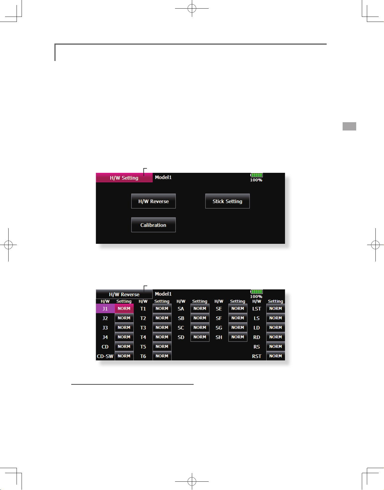
H/W Setting
Stick, switch, trim lever, and knob operation direction reversal (Hardware
reverse)/Stick response and hysterisis adjustment (Stick Setting)/Calibration
This function is for adjusting the sticks, switches,
and trim characteristics. It is not unless necessary.
H/W Reverse
This function reverses the operation signal of the
sticks, switches, trimmer levers, and knobs.
Note: This setting reverses the actual operation
signal, but does not change the display of
the indicators on the display. Use the Normal
mode as long as there is no special reason to
use the Reverse mode.
● Touch the [H/W Setting] button at the System
Menu to call the setup screen shown below.
●Return to System Menu
Stick Setting
This function sets the servo response and
hysteresis for stick operation for each condition.
The control feeling of the stick can be adjusted to
match the aerobatics.
Calibration
Usually, this calibration is unnecessary.
Please perform this calibration, only if a change
at the center of a stick should arise after prolonged
use.
● Touch the [H/W Reverse] button at the H/W
Setting Menu to call the setup screen shown
below.
●Return to H/W Setting Menu
Operation direction reversal method
1. Touch the setting button corresponding to
the H/W (Hardware) you want to reverse.
2. Reverse the H/W by touching [Yes]. (When
you want to stop operation, touch [No].)
[Normal]: Normal operation direction
[Reverse]: Reverses the operation direction.
<System Menu>
47
Page 48

● Touch the [Stick Setting] button at the H/W Setting
Menu to call the setup screen shown below.
●Return to H/W Setting Menu
● Group/single mode switching (Gr./Sngl)
(For more information, see the description at the back of this manual.)
Response adjustment
1. Touch the setting button corresponding to
the stick whose response you want to adjust.
Adjustment buttons appear on the righthand side of the stick setup screen.
2. Use the adjustment buttons to adjust the
response.
Initial value: 4
Adjustment range: 1~16 (When the
adjustment value is large, the response
becomes slow.)
● Touch the [Calibration] button at the H/W Setting
Menu to call the setup screen shown below.
●Return to H/W Setting Menu
Hysteresis adjustment
1. Touch the setting button corresponding to
the stick whose hysteresis you want to adjust.
Adjustment buttons appear on the righthand side of the stick setup screen.
2. Use the adjustment buttons to adjust the
hysteresis.
Initial value: 1
Adjustment range: 0~32 (When the
adjustment value is large, the hysteresis value
becomes large.)
How to Calibrate
1. Choose the stick to calibrate right and left.
2. The stick is set at neutral and the [neutral]
button is pushed.
3. The stick is held at full right and full bottom
(diagonal) the [Right/Bottom] button is
pushed.
4. The stick is held at full left and full top
(diagonal) the [Left/ Top] button is pushed.
<System Menu>
48
*Please do not press the stick too rmly in any direction when
doing the calibration.
*Check after calibration to make sure that neutral is 0% and
bottom right side will be +100%, and the top left side is
become -100%.
Page 49

Sound Volume
Sound Volume setting
This function can set the volume of "Key
Operation" "Error/Warning" "Trim&Center Click"
"Timer Event" respectively.
*If you have set the PIN try not to forget it. When a system
PIN is set, if you forget the PIN, none of the settings can be
changed or entered. In this case, the system must be reset by
the Futaba Service Center.
● Touch the [Sound Volume] button in the System
Menu to call the setup screen shown below.
●Return to System Menu
Sound Volume
Key Operation
Model 1
85%
Error/Warning
-
Trim & Center Click
-
+
+
Sound Volume Setting method
1. When the Sound Volume box is touched, the
above screen will appear.
2. You can change the sound volume by
touching the "+" "-" button of four items.
*If you touch "+", the volume will increase. If you touch the
"-", the volume will decrease.
-
Timer Event
-
+
+
<System Menu>
49
Page 50

Player
Music playback
The T18MZ transmitter can play back ".wma" music les stored in your SD card and USB memory. You
can listen to them through the built-in speaker or through the headphone jack with your own headphones.
[Important notice]
Before downloading les from your PC into the
SD card, insert the SD card into the transmitter
and turn on the power of the transmitter. Then
the following folders will be automatically
created in the SD card. When you download les
from you PC, copy and paste the les into their
corresponding les.
• BMP : picture les
• WMA : music les
• WAV : sound les
• Push the Music Playback button on the home
screen to call the following set-up screen.
• MODEL : model data les
• Return to the home screen
Player
00:00:00 / 00:00:00
-
Model 1
+
Buttons for music playback
• You can playback any music
files listed on the right side of
the screen.
• If you adjust the volume here, it
adjusts not only music playback
but also other applications.
Copy / Delete / Rename
1. Data is chosen from Playback File.
2. Selected data is pushed.
3. Copy / Delete / Rename is chosen from a
right display.
4. Next, it chooses in [Yes] and [No]. In Rename,
name is inputted into the keyboard which
appeared, and, nally it pushes Enter.
• Button to select either One-time
Playback or Repeat Playback
85%
Playback File
File not found !
Sel.SW
•Button to
select either
One Music
Playback or
Multiple Music
Playback
• SW selection button
Push this button to call the SW
select screen and choose the
Music playback switch.
(Refer to the description in the
end of this manual)
(Playback le list)
To playback
• All the music files saved in the T18MZ/SD
card/USB memory will be shown here.
1. Push the file name to select the music file
you want to hear.
2. Use the buttons on the left to playback or
stop the music.
<System Menu>
50
Page 51

Camera
Camera photography and picture storage
Pictures can be easily taken with the camera
in the T18MZ. The picture can be saved to the
T18MZ, SD card, and USB memory. Your favorite
model photographed by you can be displayed on
the Home screen, Start screen, and Model Select
screen.
● Call the following setting screen by pressing the
[Camera] button in the System Menu.
●Return to System Menu
Camera
Thumbnail
Save to...
●Picture data save destination (T18MZ, SD card, USB memory)
Model1
●To the thumbnail screen to view all pictures.
Shooting method
1. Turn on the transmitter and call [Camera]
from the System Menu.
2. Select the picture save destination. (T18MZ,
SD card, USB memory)
*Only when an SD card and USB memory are used will an
icon be displayed and this choice can be selected.
3. Point the camera at the back of the
transmitter toward the subject and press the
shutter button.
4. The picture can be checked with the
[Thumbnail] button. A picture can be copied
and deleted by pressing it.
Copy / Delete / Rename
1. [Thumbnail] button is pushed.
2. Data is chosen from Thumbnail.
3. Copy / Delete / Rename is chosen from a
right display.
4. Next, it chooses in [Yes] and [No]. In Rename,
name is inputted into the keyboard which
appeared, and, nally it pushes Enter.
Camera
●shutter button
85%
Display pictures at the model data
1. Call [Camera] from the System Menu.
2. Make the save destination the same place
as model data. If an SD card or USB memory
is not connected, the T18MZ becomes the
initial state.
3. Take the picture you want to display with the
T18MZ.
(Position the picture inside the frame.)
4. Select the model whose picture you want to
paste beforehand.
5. Press [Thumbnail] and then press the picture
you took earlier.
6. Press[Entry].
7. The message “Sure?” is displayed. Press [Yes].
<System Menu>
51
Page 52

S.BUS Servo
S.BUS servo setting
An S.BUS servo can memorize the channel
and various settings itself. Servo setting
can be performed on the T18MZ screen
by wiring the servo as shown in the figure.
●Servo ID number
Individual ID numbers are memorized for your
S.BUS servos in your T18MZ. When a servo is
used (as shown at the right), the servo ID number is
automatically read by the transmitter.
If you use multiple S.BUS servos and do not want
to change the settings on all that are mounted in a
fuselage, only the desired servo in the group can be
set by entering the ID of that specic servo.
HUB
orY-adapter
* S9070SB cannot be arranged by T18MZ.
* With S.BUS servos of use, there are a function which can be used, and an impossible
function and a display screen changes.
(Only the function which can be used by a servo is displayed.)
● Call the following setting screen by pressing the
[S.BUS Servo] button in the System Menu.
●Return to System Menu
S.BUSservo ReceiverBattery
Procedure for changing S.BUS servo setting
1. Select [S.BUS Servo] of the System Menu.
2. Wire the servo as shown in the gure above.
3. Press [Recall]. The ID and current setting of
that servo are displayed.
4. When multiple servos are connected change
[INH] at the right side of the ID number on the
screen to [ACT] and enter the ID of the servo
you want to set.
5. Set each item. (Please see the next page.)
6. Press [Write]. The settings are changed.
<System Menu>
52
Page 53

S.BUS Servo Description of function of each parameter
*There are a function which can be used according to the kind of servo, and an impossible function.
• ID
Displays the ID of the servo whose parameters are to be read. It cannot be changed.
• Channel
Channel of the
• Reverse
The direction in which the servo rotates can be changed.
• Servo type
When “Retractable” is selected and the servo has been continuously stopped for 30 seconds, the dead band
expands and unnecessary hold current due to external force is eliminated. When a new control signal enters,
normal operation is resumed. When using the servo as a landing gear servo, select “Retractable”. Also adjust the
servo travel to match the landing gear movement range.
• Soft Start
Restricts operation in the specified direction the instant the power is turned on. By using this setting, the first initial
movement when the power is turned on slowly moves the servo to the specified position.
• Stop Mode
The state of the servo when the servo input signal is lost can be specified. The "Hold" mode setting holds the
servo in its last commanded position even if using AM or FM system.
• Smoother
This function changes smoothness of the servo operation relative to stick movement changes. Smooth setting is
used for normal flight. Select the "OFF" mode when quick operation is necessary such as 3D.
• Neutral Offset
The neutral position can be changed. When the neutral offset is large value, the servo's range of travel is restricted
on one side.
• Speed Control
Speeds can be matched by specifying the operating speed. The speed of multiple servos can be matched without
being affected by motor fluctuations. This is effective for load torques below the maximum torque.
However, note that the maximum speed will not be exceed what the servo is capable of even if the servos
operating voltage is increased.
• Dead band
The dead band angle at stopping can be specified.
[Relationship between dead band set value and servo operation]
Small → Dead band angle is small and the servo is immediately operated by a small signal change.
Large → Dead band angle is large and the servo does not operate at small signal changes.
(Note) If the dead band angle is too small, the servo will operate continuously and the current consumption will
increase and the life of the servo will be shortened.
• Travel Adjust
The left and right travels centered about the neutral position can be set independently.
• Boost
The minimum current applied to the internal motor when starting the servo can be set. Since a small travel does
not start the motor, it essentially feels like the dead band was expanded. The motor can be immediately started by
adjusting the minimum current which can start the motor.
[Relationship between boost set value and servo operation]
Small → Motor reacts to a minute current and operation becomes smooth.
Large → Initial response improves and output torque increases. However, if the torque is too large, operation will
S.BUS
system assigned to the servo. Always assign a channel before use.
become rough.
<System Menu>
53
Page 54

• Boost ON/OFF
OFF : It is the boost ON at the time of low-speed operation.(In the case of usual)
ON : It is always the boost ON.(When quick operation is hope)
• Damper
The characteristic when the servo is stopped can be set.
When smaller than the standard value, the characteristic becomes an overshoot characteristic. If the value is
larger than the standard value, the brake is applied before the stop position.
Especially, when a large load is applied, overshoot, etc. are suppressed by inertia and hunting may occur,
depending on the conditions. If hunting (phenomena which cause the servo to oscillate) occurs even though the
Dead Band, Stretcher, Boost and other parameters are suitable, adjust this parameter to a value larger than the
initial value.
[Relationship between damper set value and servo operation]
Small → When you want to overshoot. Set so that hunting does not occur.
Large → When you want to operate so that braking is not applied. However, it will feel like the servo response has
(Note) If used in the hunting state, not only will the current consumption increase, but the life of the servo will also
be shortened.
worsened.
• Stretcher
The servo hold characteristic can be set. The torque which attempts to return the servo to the target position
when the current servo position has deviated from the target position can be adjusted.
This is used when stopping hunting, etc., but the holding characteristic changes as shown below.
[Relationship between stretcher and servo operation]
Small → Servo holding force becomes weaker.
Large → Servo holding force becomes stronger.
(Note) When this parameter is large, the current consumption increases.
• Buzzer
When the power supply of a servo is previously turned on at the time of a power supply injection without taking
transmit of a transmitter, the buzzer sound of about 2.5 Hz continues sounding from a servo.
(Even when the transmit of a transmitter is taken out previously, a buzzer becomes until the signal of a servo is
outputted normally, but it is not unusual.)
The transmitter has been turned OFF ahead of a servo power supply→ The buzzer sound of about 1.25 Hz
continues sounding as servo power supply end failure alarm.
(
Do not insert or remove the servo connector while the receiver power is ON. A buzzer may sound
by incorrect recognition.
Buzzer sound is generated by vibrating the motor of a servo.
*
Since current is consumed and a servo generates heat, please do not operate the number more than needed or
do not continue sounding a buzzer for a long time.
<System Menu>
54
)
Page 55

Information
The program version, CF card/USB memory data, and product ID are displayed.
The language used by the system can also be changed.
The Information screen displays the T18MZ
system program version information, T18MZ
,SD card and USB memory (memory size, vacant
capacity, number of model data, and number of
music les) information and product ID.
● Touch the [Information] button at the System
Menu to call the setup screen shown below.
●Return to System Menu
*When an SD card and USB memory are not inserted, their
information is not displayed.
<System Menu>
55
Page 56

Range Check
Before a ight ground range check.
The 'range check mode' reduces the transmission
range of the radio waves to allow for a ground
range check.
*The range check mode, when activated, will continue for90
seconds unless the user exits this mode early. When the
progress bar reaches 90 second mark, the RF transmission
automatically returns to the normal operating power.
Warning
Do not fly in the range check mode.
*Since the range of the radio waves is short, if the
model is too far from the transmitter, control will
be lost and the model will crash.
● Pushing [ S4 ]Key is continued. →Turn ON the transmitter's power switch
→[ S4 ]Key will be released if the screen of "Transmit?" comes out.
● Touch the [Range Check] button at the System
Menu to call the setup screen shown below.
● [NO] is pushed.
Rotation Range Check method
1. Pushing [ S4 ]Key is continued. →Turn ON the
transmitter's power switch. Select [No] .
*For safety, the RANGE CHECK mode can not be selected
while the RF transmission is active.
2. In the system menu, choose the 'Range
Check' selection from the menu options.
3. The Range Check screen is displayed. To
activate the Range Check mode press
the [Yes] button. During the Range Check
period, the RF power is reduced to allow the
ground range tests to be performed.
4. The Range Check function automatically
exits after the 90 second time limit has
expired. The progress bar is displayed on the
transmitter's screen. Should you complete
the range check before the 90 seconds has
pressed, press the [Exit] button.
*When the [RESTART] botton is pressed, the range check
mode timer is returned to 0.
<System Menu>
56
● [Yes] is pushed.
*Please note, upon expiration of the 90 seconds, or when [Exit]
is selected, the transmitter will automatically return to the
normal RF operation as noted on the display.
*Once the 18MZ is transmitting at full power, it is not
possible to enter the Range Check mode without first
switching the transmitter Off and back On. This has been
designed to prevent a modeler from inadvertently flying in
the Range Check mode.
5. When the [Exit] button is pressed, the Range
Check mode is disabled and the 18MZ will
begin transmitting at full power.
*After exiting the Range Check mode, the function cannot be
selected again. To select the Range Check mode again you
must cycle the transmitter power switch.
Page 57

MODEL BASIC SETTING PROCEDURE
Airplane/glider basic setting procedure
1. Model addition and call
Initial setting assigns one model to the T18MZ
transmitter. The Model Select function of the
Linkage Menu is used to add models and to select
models which have already been set.
This is convenient when calling a model after its
name has been registered. (Data can also be saved to
the accessory SD card and USB memory)
The currently called model name is displayed at the
top of the screen. Before flying and before changing
any settings, always conrm the model name.
When a new model was added, the Model type
select screen/System Type/Receiver link automatically
appear. Please be aware that the transmitter will stop
transmitting when you change the model.
3. Fuselage linkage
Link the ailerons, elevators, throttle, rudder, etc.
in accordance with the model's instruction manual.
For a description of the connection method, see the
Receiver and Servos Connection.
Note: The channel assignment of the T18MZ is
different from that of our existing systems. Note
that even for the same "airplane model", when the
wing type and tail type are different, the channel
assignment have been optimized and may be
different. (The channel assigned to each function
can be checked in the Function menu of the
Linkage Menu.)
2. Model type selection
Select the model type matched to the fuselage with
the Model Type select function of the Linkage Menu.
For an airplane, select the model type from among the
3 types: airplane, glider, and motor glider. When the
Wing type select screen is displayed and the wing type
is selected when selecting the model type, the Tail type
select screen is displayed. Select the tail type matched
to the fuselage.
There are 13 wing types and 3 tail types for airplane,
glider, and motor glider.
● When the direction of the linkage is reversed,
adjust the direction with the Servo Reverse
function in the Linkage Menu.
● Connect the throttle linkage so the carburetor
is open at full trim and full open so that the
throttle can be cut.
● Adjust the neutral position and rudder angle
with the linkage, and fine tune them with
the Sub Trim and End Point functions (rudder
angle adjustment). To protect the linkage, a
limit position can also be set with the End Point
function. The End Point function can adjust the
amount of up/down and left/right movement,
limit, and servo speed of each channel.
<Model Basic Setting Procedure>
57
Page 58

4. Throttle cut setting
Throttle cut can be performed with one touch by a
switch without changing the throttle trim position.
Set throttle cut with the Throttle Cut function of
the Linkage Menu. After activating the throttle cut
function and selecting the switch, adjust the throttle
position so that the carburetor becomes full open. For
safety, the throttle cut function operates the throttle
stick in the slow position.
5. Idle down setting
The idling speed can be lowered with one touch by
a switch without changing the throttle trim position.
Perform this setting with the Idle Down function of the
Linkage Menu. After activating the Idle Down function
and selecting the switch, adjust the idle down speed.
For safety, the idle down function acts only when the
throttle stick is in the slow position.
*While the Throttle Cut function is in operation, the Idle
Down function does not work.
6. AFR (D/R)
AFR function is used to adjust the throw and
operation curve of the stick, lever, and switch functions
for each flight condition. This is normally used after
End Point (ATV) has defined the maximum throw
directions (End Point acts on ALL flight condition
settings). When mixing is applied from one channel to
another channel, both channels can be adjusted at the
same time by adjusting the operation rate through the
AFR function.
The preset elevators and flaps (camber flap, brake
ap) offset amount can be activated by a switch.
The offset amount of the aileron, elevator, and ap
servos can be adjusted as needed. Also the speed of the
aileron, elevator, and ap servos can be adjusted. (IN
side/OUT side) A delay can be set for each condition,
and a Cut switch which will turn OFF the delay can be
chosen. Trim amounts can be fine-tuned by setting a
VR . You can also set the Auto Mode, which will link
Airbrake to a stick, switch, or dial. A separate stick
switch or dial can also be set as the ON/OFF switch.
8. Addition of ight conditions
The transmitter can install up to eight flight
conditions per model. You can assign all switches
including sticks, switches, trim levers and trim
switches as ight-condition selection switches. You
can also add delayed mixing to these functions in
order to avoid sudden changes. Moreover, you can
set priority order for ight conditions when you set
more than one condition. In addition, you can copy
conditions and/or change names of conditions. This
command may also be used to dene what switches
and/or controls are used to activate each flight
condition.
The Condition Select function automatically
allocates the Condition 1 for each model type.
Condition 1 is the default condition, also referred to
as Normal, and is the only one active when a new
model type is dened. This condition is always on,
and remains on until other conditions are activated
by switches.
The Condition Delay can be programmed for each
channel. The Condition Delay is used to change the
servo throw smoothly when switching conditions.
7. Airbrake
This function is used when an air brake is necessary
when taking off or diving, etc.
<Model Basic Setting Procedure>
58
*When a new condition is added, "Condition1" data is
automatically copied.
*Select the condition switch and set the new condition data
with the switch in the ON position. However, if the group
mode (Gr.) was selected in advance, the same data will be
input to all new conditions. Select the single mode (Sngl)
and adjust the condition you want to change.
Page 59

Helicopter basic setting procedure
1. Model addition and call
Default settings assign one model to the T18MZ
transmitter. To add new models or select previously
setup models, use the Model Select function in the
Linkage Menu.
This is convenient when calling a model after
registering the model names in advance. (Data can also
be saved to the accessory SD card and USB memory)
The currently called model is displayed at the top
of the screen. Before ying and before changing any
settings, always conrm the model name.
Please be aware that the transmitter will stop
transmitting when you change the model.
When a new model was added, the Model type select
screen/System mode/Receiver link automatically
appear. Please be aware that the transmitter will
stop transmitting when you change the model.
3. Flight condition addition
The transmitter can install up to eight flight
conditions per model. You can assign all switches
including sticks, switches, trim levers and trim switches
as flight-condition selection switches. You can also
add delayed mixing to these functions in order to
avoid sudden changes. Moreover, you can set priority
order for ight conditions when you set more than one
condition. In addition, you can copy conditions and/or
change names of conditions. This command may also
be used to define what switches and/or controls are
used to activate each ight condition.
The Condition Select function automatically
allocates the default Condition 0 (Normal) for each
model type. Condition 0 (Normal) is the only one active
when a new model type is defined. This condition is
always on, and remains on until other conditions are
activated by switches.
The Condition Delay can be programmed for each
channel. The Condition Delay is used to change the
servo throw smoothly when switching conditions.
2. Model type and swash type selection
When a separate model type is already selected,
select helicopter with the Model Type function of the
Linkage Menu, and then select the swash type matched
to the fuselage.
(General ight condition setting example)
● Normal: (Use initial setting conditions/operate
when switch OFF)
Use from engine starting to hovering.
● Idle up 1: (Switch setting example: Operate
at SW-E center)
Use in stall turn, loop, and other maneuvers.
● Idle up 2: (Switch setting example: Operate
at SW-E forward side)
Use in rolls.
● Throttle hold: (Switch setting example:
Operate at SW-G forward side)
Use in auto rotation.
The priority is throttle hold/idle up 2/idle up 1/
normal. Throttle hold has the highest priority.
Add other conditions, as required.
<Model Basic Setting Procedure>
59
Page 60

4. Fuselage linkage
Connect the throttle rudder, ailerons, elevators,
pitch, and other rudder linkages in accordance with
the kit instruction manual. For a description of
the connection method, see "Receiver and Servos
Connection".
*The channel assignment of the T18MZ is different from
that of our existing systems. (The channel assigned to
each function can be checked at the Function menu of the
Linkage Menu.)
● Swash plate correction (Except H-1 mode)
Operation of the swash plate near the hovering
point can be corrected by swash AFR function
correction mixing. Use this when pitch, aileron,
and elevator operation causes the swash plate to
deviate from the normal direction.
(Call the Swash setup→Swash details screen.)
Pitch slow side and high side linkage correction is
also possible. Adjust so that pitch operation causes
the swash plate to move up and down in the
horizontal state.
● When the direction of the linkage is reversed,
use the Reverse function of the Linkage
Menu. Also use the swash AFR function in any
swash set up other than the H-1 mode.
● Adjust the direction of operation of the gyro.
(Gyro side function)
● Connect the throttle linkage so that the
carburetor becomes full open at full trim
throttle cut is possible.
● Adjust the neutral position andrudder angle
at the linkage side and fine tune with the
Sub-Trim function and End Point function
(rudder angle adjustment). To protect the
linkage, a limit position can also be set with
the End Point function.
5. Throttle curve setting
This function adjusts the pitch operation curve
in relation to the movement of the throttle stick for
each condition.
(17 points curve)
The pitch curve can be freely selected from linear
operation curve to smooth curve, and adjusted to
match the curve you want by means of the T18MZ’s
powerful Curve Edit Function (6 types of curves can
be selected). Up to 17 points can be set for linear
or curve types. However, when using the 3 points
or 5 points specied to create a curve, a simple and
smooth curve can be created by selecting the curve
type and reducing the number of input points to 3
or 5, and then entering the specified value at the
corresponding points that you created.
<Setting example>
Call the throttle curve of each condition with the
condition select switch.
●Normal curve adjustment
Normal curve uses Normal (Linear) type and creates
a basic pitch curve centered near hovering. This
curve is adjusted together with the Throttle Curve
(Normal) so that the engine speed is constant and
up/down control is easiest.
●Idle up curve adjustment
The high side pitch curve sets the maximum pitch
regardless of the engine load. The low side pitch
curve creates a curve matched for aerobatics
(loop, roll, 3D, etc.).
Note: When the curve type is changed, the data is reset.
<Model Basic Setting Procedure>
60
Page 61

●Throttle hold curve adjustment
The throttle hold curve is used when performing
auto rotation dives.
Conrm that the rate of the slowest position (0%) of
the stick is 0% (initial setting).
Be sure that when set to high side 100%, the curve
of any condition does not exceed 100%.
Example of pitch curve setting:
1. Call the pitch curve of each condition with
the condition select switch.
*Pitch curve graph display can be switched to pitch angle
direct reading display.
A. Pitch curve (Normal)
Make the pitch at hovering approximately +5º~6º.
Set the pitch at hovering with the stick position at
the 50% point as the standard.
*Stability at hovering may be connected to the throttle curve.
Adjustment is easy by using the hovering throttle function
and hovering pitch function together.
B. Pitch curve (Idle up 1)
The idle up 1 pitch curve function creates a curve
matched to airborne ight.
Set to -7º~+12º as standard.
C. Pitch curve (Idle up 2)
The high side pitch setting is less than idle up 1.
The standard is +8º.
D. Pitch curve (Hold)
At auto rotation, use the maximum pitch at both
the high and low sides.
[Pitch angle setting example]
Throttle hold: -7º~+12
º
manipulation, the Auto mode can be set.
When you want to adjust the servo speed, adjust
[Speed].
7. Pitch to RUD mixing setting
Use this function when you want to suppress
the torque generated by the changes in the pitch
and speed of the main rotor during pitch operation.
Adjust it so that the nose does not swing in the
rudder direction. However, when using a heading
hold gyro like those shown below, do not use Pitch
to RUD mixing.
Note: When using a GY701, GY601, GY502, GY401,
or other heading hold gyro, this Pitch to RUD
mixing should not be used. The reaction torque is
corrected at the gyro side. When operating the
gyro in the AVCS mode, the mixed signal will cause
neutral deviation symptoms and the gyro will not
operate normally.
Call the Pitch to RUD mixing function from the
Model Menu, and set the curve for each condition.
(At initial setting, this function is in the "INH"
state. To use it, set it to the "ON" state.)
6. Throttle hold setting
Call the Throttle Hold function from the Model
Menu and switch to the throttle hold condition with
the condition select switch.
Note: At initial setting, the setting mode is the
group mode. Since this function is not used at other
conditions, switch to the single mode before setting.
●Setting to the state which activates the
function
The throttle hold function allows setting for throttle
cut and switching of the function xed at the idle
position by switch for training. Either one or both
functions can be performed.
●Hold position setting
This function sets the servo operation position at
throttle hold. (Throttle cut and idle positions)
●Other settings
When you want to link operation with stick
(17 points curve)
Curve setting of up to 17 points is possible.
However, in the following setting example, a
simple curve can be adjusted by using the [Linear]
curve type.
Note: At initial setting, the setting mode is the group
mode. In this mode, the same contents are set at in
all conditions. When you want to set the selected
condition only, switch to the single mode.
<Setting example>
Call the mixing curve of each condition with the
condition select switch.
<Model Basic Setting Procedure>
61
Page 62

1. A curve setting example is shown below.
A. Pitch to RUD mixing curve (Normal)
Use the hovering system and set this curve to
match take off and landing and vertical climb at
a constant speed.
*For this curve, use the initial setting [Linear] curve type and
adjust the left and right rates in the [Separate] mode.
B. Pitch to RUD mixing (Idle up 1)
Use this curve in stall turn, loop, and adjust it so the
fuselage is facing straight ahead when heading
into the wind.
*For this curve, [Linear] curve type can be used and the entire
curve can be lowered with the [Offset] button.
C. Pitch to RUD mixing (Hold)
This function is set so that the fuselage is facing
straight ahead during straight line auto rotation.
The pitch of the tail rotor becomes nearly 0º.
*For this curve, [Linear] curve type can be used and the entire
curve can be lowered with the [Offset] button.
●Other settings
The mixing rise characteristic of pitch operation
can be adjusted. An acceleration (ACLR) function,
which temporarily increases and decreases the
mixing amount, can be set.
8. Swash Mix corrects aileron, elevator and
pitch interaction
The swash mix function is used to correct the
swash plate in the aileron (roll) direction and
elevator (cyclic pitch) corresponding to each
operation of each condition.
The gyro sensitivity and mode switching
function is dedicated gyro mixing of the Model
Menu, and can be set for each condition.
●Normal condition (hovering): Gyro sensitivity
maximum
●Idle up 1/Idle up 2/Throttle hold: Gyro
sensitivity minimum
●However, at auto rotation of a tail-driven
helicopter, this function may not have any
affect at high gyro sensitivity.
11. Throttle cut setting
Throttle cut provides an easy way to stop the
engine, by ipping a switch with the throttle stick
at idle. The action is not functional at high throttle
to avoid accidental dead sticks. The switch’s
location and direction must be chosen, as it defaults
to NULL.
9. Throttle mixing setting
RPM loss caused by swash operation of aileron
or elevator can be corrected with the Throttle
Mix function in the Model Menu. The effects of
clockwise and counterclockwise torque is applied
when pirouetting can also be corrected.
10. Gyro sensitivity and mode switching
<Model Basic Setting Procedure>
62
*With throttle stick at idle, adjust the cut position
until the engine consistently shuts off, but throttle
linkage is not binding. When finished, touch the
“Throttle Cut” button to exit.
12. Other special mixings
●Pitch to Needle mixing
This mixing is used with engines with a construction
which allows needle control during ight (fuel-air
mixture adjustment). A needle curve can be set.
The needle servo rise characteristics at throttle
stick acceleration/deceleration operation can be
adjusted. (Acceleration function)
●Fuel mixture function
This mixing is used in needle adjustment of engines
which use a fuel mixture control carburetor.
●Governor mixing
This mixing is dedicated governor mixing when a
governor is used. Up to 3 rates (speeds) can be
switched for each condition.
Page 63

Receiver and servos connection
Connect the receiver and servos in accordance with the connection diagram shown below. Always read
[Precautions when mounting the receiver and servos] and [Before using]. When mounting the receiver and
servos to the fuselage, connect the necessary points in accordance with the kit instruction manual.
Receiver and servos connection diagram
●Always connect the necessary number of servos.
●The receiver channel assignment depends on the
model type. See the Servo connection by model
type tables.
R7008SB (output connector section)
(Receiver connectors)
●1~6: Output for conventional system CH1~6
●7/B: Output for conventional system CH7/Power supply
●8/SB: Output for conventional system CH8 or S.BUS port
●S.BUS2: S.BUS2 port
●Monitor LED
Telemetry sensor etc.
S.BUS not
using it
(CH1-8)
In S.BUS
use
(8/SB)
(7/B)
Receiver battery
Charging port
Receiver switch
Servos
●The Servo connection by model type tables are shown on the following pages.
Connect the servos to match the fuselage used.
<Model Basic Setting Procedure>
63
Page 64

Servo connection by model type
The T18MZ transmitter channels are automatically assigned for optimal combination according to the
type selected with the Model Type function of the Linkage Menu. The channel assignment (initial setting)
for each model type is shown below. Connect the receiver and servos to match the type used.
*The set channels can be checked at the Function screen of the Linkage Menu. The channel assignments can also be changed. For
more information, read the description of the Function menu.
Airplane/glider/motor glider
●Airplane and V tail
RX
CH
Airplane
1 Aileron Aileron Aileron Aileron Aileron Aileron Aileron Aileron Aileron Aileron Aileron Aileron
2 Elevator Elevator Elevator Elevator Elevator Elevator Elevator Elevator Elevator Elevator Elevator Elevator
3 Throttle Motor AUX7 Throttle Motor AUX7 Throttle Motor AUX7 Throttle Motor AUX7
4 Rudder Rudder Rudder Rudder Rudder Rudder Rudder Rudder Rudder Rudder Rudder Rudder
5 Gear AUX6 AUX6 Gear AUX6 AUX6 Gear AUX6 AUX6 Aileron2 Aileron2 Aileron2
6 Airbrake Airbrake Airbrake Aileron2 Aileron2 Aileron2 Aileron2 Aileron2 Aileron2 Flap Flap Flap
7 AUX5 AUX5 AUX5 AUX5 AUX5 AUX5 Flap Flap Flap Flap2 Flap2 Flap2
8 AUX4 AUX4 AUX4 AUX4 AUX4 AUX4 AUX5 AUX5 AUX5 Gear AUX6 AUX6
9 AUX3 AUX3 AUX3 AUX3 AUX3 AUX3 AUX4 AUX4 AUX4 AUX5 AUX5 AUX5
10 AUX2 AUX2 AUX2 AUX2 AUX2 AUX2 AUX3 AUX3 AUX3 AUX4 AUX4 AUX4
11 AUX1 AUX1 AUX1 AUX1 AUX1 AUX1 AUX2 AUX2 AUX2 AUX3 AUX3 AUX3
12 AUX1 AUX1 AUX1 AUX1 AUX1 AUX1 AUX1 AUX1 AUX1 AUX2 AUX2 AUX2
13 AUX1 AUX1 AUX1 AUX1 AUX1 AUX1 AUX1 AUX1 AUX1 AUX1 AUX1 AUX1
14 AUX1 AUX1 AUX1 AUX1 AUX1 AUX1 AUX1 AUX1 AUX1 AUX1 AUX1 AUX1
15 AUX1 AUX1 AUX1 AUX1 Buttery Buttery AUX1 Buttery Buttery AUX1 Buttery Buttery
16 AUX1 AUX1 AUX1 Camber Camber Camber Camber Camber Camber Camber Camber Camber
DG1 SW SW SW SW SW SW SW SW SW SW SW SW
DG2 SW SW SW SW SW SW SW SW SW SW SW SW
RX
CH
Airplane
1 Aileron Aileron Aileron Aileron Aileron Aileron Aileron Aileron Aileron
2 Elevator Elevator Elevator Elevator Elevator Elevator Elevator Elevator Elevator
3 Throttle Rudder Rudder Throttle Rudder Rudder Throttle Rudder Rudder
4 Rudder Aileron2 Aileron2 Rudder Aileron2 Aileron2 Rudder Aileron2 Aileron2
5 Gear Flap Flap Gear Aileron3 Aileron3 Gear Aileron3 Aileron3
6 Aileron2 Flap2 Flap2 Aileron2 Aileron4 Aileron4 Aileron2 Aileron4 Aileron4
7 Flap Flap3 Flap3 Aileron3 Flap Flap Aileron3 Flap Flap
8 Flap2 Flap4 Flap4 Aileron4 Flap2 Flap2 Aileron4 Flap2 Flap2
9 Flap3 Motor AUX7 Flap Motor AUX7 Flap Flap3 Flap3
10 Flap4 AUX6 AUX6 Flap2 AUX6 AUX6 Flap2 Flap4 Flap4
11 AUX5 AUX5 AUX5 AUX5 AUX5 AUX5 Flap3 Motor AUX7
12 AUX4 AUX4 AUX4 AUX4 AUX4 AUX4 Flap4 AUX6 AUX6
13 AUX3 AUX3 AUX3 AUX3 AUX3 AUX3 AUX5 AUX5 AUX5
14 AUX2 AUX2 AUX2 AUX2 AUX2 AUX2 AUX4 AUX4 AUX4
15 AUX1 Buttery Buttery AUX1 Buttery Buttery AUX3 Buttery Buttery
16 Camber Camber Camber Camber Camber Camber Camber Camber Camber
DG1 SW SW SW SW SW SW SW SW SW
DG2 SW SW SW SW SW SW SW SW SW
1AIL 2AIL 2AIL+1FLAP 2AIL+2FLAP
Glider
EP EP EP EP
Airplane
2AIL+4FLAP 4AIL+2FLAP 4AIL+4FLAP
Glider
EP EP EP
Airplane
Glider
Glider
Airplane
Airplane
Glider
Glider
Airplane
CH of each
system
FASST 7CH
S-FHSS
FASSTest 12CH
The output
FASSTest 18CH FASST MULT
Glider
FASST 7CH
CH of each
system
S-FHSS
FASSTest 12CH
The output
FASSTest 18CH FASST MULT
<Model Basic Setting Procedure>
64
Page 65

●Ailevator
RX
CH
Airplane
1 Aileron Aileron Aileron Aileron Aileron Aileron Aileron Aileron Aileron Aileron Aileron Aileron
2 Elevator Elevator Elevator Elevator Elevator Elevator Elevator Elevator Elevator Elevator Elevator Elevator
3 Throttle Motor AUX7 Throttle Motor AUX7 Throttle Motor AUX7 Throttle Motor AUX7
4 Rudder Rudder Rudder Rudder Rudder Rudder Rudder Rudder Rudder Rudder Rudder Rudder
5 Gear AUX6 AUX6 Gear AUX6 AUX6
6 Airbrake Airbrake Airbrake Aileron2 Aileron2 Aileron2 Aileron2 Aileron2 Aileron2 Aileron2 Aileron2 Aileron2
Elevator2 Elevator2 Elevator2 Elevator2 Elevator2 Elevator2
7
8 AUX5 AUX5 AUX5 AUX5 AUX5 AUX5 Gear AUX6 AUX6 Flap2 Flap2 Flap2
9 AUX4 AUX4 AUX4 AUX4 AUX4 AUX4 AUX5 AUX5 AUX5 Gear AUX6 AUX6
10 AUX3 AUX3 AUX3 AUX3 AUX3 AUX3 AUX4 AUX4 AUX4 AUX5 AUX5 AUX5
11 AUX2 AUX2 AUX2 AUX2 AUX2 AUX2 AUX3 AUX3 AUX3 AUX4 AUX4 AUX4
12 AUX1 AUX1 AUX1 AUX1 AUX1 AUX1 AUX2 AUX2 AUX2 AUX3 AUX3 AUX3
13 AUX1 AUX1 AUX1 AUX1 AUX1 AUX1 AUX1 AUX1 AUX1 AUX2 AUX2 AUX2
14 AUX1 AUX1 AUX1 AUX1 AUX1 AUX1 AUX1 AUX1 AUX1 AUX1 AUX1 AUX1
15 AUX1 AUX1 AUX1 AUX1 Buttery Buttery AUX1 Buttery Buttery AUX1 Buttery Buttery
16 AUX1 AUX1 AUX1 Camber Camber Camber Camber Camber Camber Camber Camber Camber
DG1 SW SW SW SW SW SW SW SW SW SW SW SW
DG2 SW SW SW SW SW SW SW SW SW SW SW SW
RX
CH
Airplane
1 Aileron Aileron Aileron Aileron Aileron Aileron Aileron Aileron Aileron
2 Elevator Elevator Elevator Elevator Elevator Elevator Elevator Elevator Elevator
3 Throttle Motor AUX7 Throttle Motor AUX7 Throttle Motor AUX7
4 Rudder Rudder Rudder Rudder Rudder Rudder Rudder Rudder Rudder
Elevator2 Elevator2 Elevator2 Elevator2 Elevator2 Elevator2 Elevator2 Elevator2 Elevator2
5
6 Aileron2 Aileron2 Aileron2 Aileron2 Aileron2 Aileron2 Aileron2 Aileron2 Aileron2
7 Flap Flap Flap Aileron3 Aileron3 Aileron3 Aileron3 Aileron3 Aileron3
8 Flap2 Flap2 Flap2 Aileron4 Aileron4 Aileron4 Aileron4 Aileron4 Aileron4
9 Flap3 Flap3 Flap3 Flap Flap Flap Flap Flap Flap
10 Flap4 Flap4 Flap4 Flap2 Flap2 Flap2 Flap2 Flap2 Flap2
11 Gear AUX6 AUX6 Gear AUX6 AUX6 Flap3 Flap3 Flap3
12 AUX5 AUX5 AUX5 AUX5 AUX5 AUX5 Flap4 Flap4 Flap4
13 AUX4 AUX4 AUX4 AUX4 AUX4 AUX4 Gear AUX6 AUX6
14 AUX3 AUX3 AUX3 AUX3 AUX3 AUX3 AUX5 AUX5 AUX5
15 AUX2 Buttery Buttery AUX2 Buttery Buttery AUX4 Buttery Buttery
16 Camber Camber Camber Camber Camber Camber Camber Camber Camber
DG1 SW SW SW SW SW SW SW SW SW
DG2 SW SW SW SW SW SW SW SW SW
1AIL 2AIL 2AIL+1FLAP 2AIL+2FLAP
Glider
EP EP EP EP
Airplane
2AIL+4FLAP 4AIL+2FLAP 4AIL+4FLAP
Glider
EP EP EP
Airplane
Glider
Glider
Airplane
Elevator2 Elevator2 Elevator2 Elevator2 Elevator2 Elevator2
Glider
Airplane
Flap Flap Flap Flap Flap Flap
The output
CH of each
system
Airplane
Glider
FASST 7CH
S-FHSS
FASSTest 12CH
Glider
FASSTest 18CH FASST MULT
CH of each
system
FASST 7CH
S-FHSS
FASSTest 12CH
The output
FASSTest 18CH FASST MULT
<Model Basic Setting Procedure>
65
Page 66

●Tailless wing
RX
Airplane
CH
1 Aileron Aileron Aileron Aileron Aileron Aileron Aileron Aileron Aileron
2 AUX4 AUX4 AUX4 AUX4 AUX4 AUX4 AUX4 AUX4 AUX4
3 Throttle Motor AUX7 Throttle Motor AUX7 Throttle Motor AUX7
4 Rudder Rudder Rudder Rudder Rudder Rudder Rudder Rudder Rudder
5 Gear AUX6 AUX6 Gear AUX6 AUX6 Aileron2 Aileron2 Aileron2
6 Aileron2 Aileron2 Aileron2 Aileron2 Aileron2 Aileron2 Flap Flap Flap
7 AUX5 AUX5 AUX5 Flap Flap Flap Flap2 Flap2 Flap2
8 AUX3 AUX3 AUX3 AUX5 AUX5 AUX5 Gear AUX6 AUX6
9 AUX2 AUX2 AUX2 AUX3 AUX3 AUX3 AUX5 AUX5 AUX5
10 AUX1 AUX1 AUX1 AUX2 AUX2 AUX2 AUX3 AUX3 AUX3
11 AUX1 AUX1 AUX1 AUX1 AUX1 AUX1 AUX2 AUX2 AUX2
12 AUX1 AUX1 AUX1 AUX1 AUX1 AUX1 AUX1 AUX1 AUX1
13 AUX1 AUX1 AUX1 AUX1 AUX1 AUX1 AUX1 AUX1 AUX1
14 AUX1 AUX1 AUX1 AUX1 Buttery Buttery AUX1 Buttery Buttery
15 Camber Camber Camber Camber Camber Camber Camber Camber Camber
16 Elevator Elevator Elevator Elevator Elevator Elevator Elevator Elevator Elevator
DG1 SW SW SW SW SW SW SW SW SW
DG2 SW SW SW SW SW SW SW SW SW
2AIL 2AIL+1FLAP 2AIL+2FLAP
Glider
EP EP EP
Airplane
Glider
Airplane
Glider
CH of each
system
FASST 7CH
S-FHSS
FASSTest 12CH
The output
FASSTest 18CH FASST MULT
RX
CH
2AIL+4FLAP 4AIL+2FLAP 4AIL+4FLAP
Airplane
Glider
EP EP EP
Airplane
Glider
Airplane
Glider
1 Aileron Aileron Aileron Aileron Aileron Aileron Aileron Aileron Aileron
2 Aileron2 Aileron2 Aileron2 Aileron2 Aileron2 Aileron2 Aileron2 Aileron2 Aileron2
3 Throttle Motor AUX7 Throttle Motor AUX7 Throttle Motor AUX7
4 Rudder Rudder Rudder Rudder Rudder Rudder Rudder Rudder Rudder
5 Flap Flap Flap Aileron3 Aileron3 Aileron3 Aileron3 Aileron3 Aileron3
6 Flap2 Flap2 Flap2 Aileron4 Aileron4 Aileron4 Aileron4 Aileron4 Aileron4
7 Flap3 Flap3 Flap3 Flap Flap Flap Flap Flap Flap
8 Flap4 Flap4 Flap4 Flap2 Flap2 Flap2 Flap2 Flap2 Flap2
9 AUX4 AUX4 AUX4 AUX4 AUX4 AUX4 Flap3 Flap3 Flap3
10 Gear AUX6 AUX6 Gear AUX6 AUX6 Flap4 Flap4 Flap4
11 AUX5 AUX5 AUX5 AUX5 AUX5 AUX5 AUX4 AUX4 AUX4
12 AUX3 AUX3 AUX3 AUX3 AUX3 AUX3 Gear AUX6 AUX6
13 AUX2 AUX2 AUX2 AUX2 AUX2 AUX2 AUX5 AUX5 AUX5
14 AUX1 Buttery Buttery AUX1 Buttery Buttery AUX3 Buttery Buttery
15 Camber Camber Camber Camber Camber Camber Camber Camber Camber
16 Elevator Elevator Elevator Elevator Elevator Elevator Elevator Elevator Elevator
DG1 SW SW SW SW SW SW SW SW SW
DG2 SW SW SW SW SW SW SW SW SW
CH of each
system
FASST 7CH
S-FHSS
FASSTest 12CH
The output
FASSTest 18CH FASST MULT
<Model Basic Setting Procedure>
66
Page 67

●Tailless wing Winglet 2Rudder
RX
Airplane
CH
1 Aileron Aileron Aileron Aileron Aileron Aileron Aileron Aileron Aileron
2 RUD2 RUD2 RUD2 RUD2 RUD2 RUD2 RUD2 RUD2 RUD2
3 Throttle Motor AUX7 Throttle Motor AUX7 Throttle Motor AUX7
4 Rudder Rudder Rudder Rudder Rudder Rudder Rudder Rudder Rudder
5 Gear AUX6 AUX6 Gear AUX6 AUX6 Aileron2 Aileron2 Aileron2
6 Aileron2 Aileron2 Aileron2 Aileron2 Aileron2 Aileron2 Flap Flap Flap
7 AUX5 AUX5 AUX5 Flap Flap Flap Flap2 Flap2 Flap2
8 AUX3 AUX3 AUX3 AUX5 AUX5 AUX5 Gear AUX6 AUX6
9 AUX2 AUX2 AUX2 AUX3 AUX3 AUX3 AUX5 AUX5 AUX5
10 AUX1 AUX1 AUX1 AUX2 AUX2 AUX2 AUX3 AUX3 AUX3
11 AUX1 AUX1 AUX1 AUX1 AUX1 AUX1 AUX2 AUX2 AUX2
12 AUX1 AUX1 AUX1 AUX1 AUX1 AUX1 AUX1 AUX1 AUX1
13 AUX1 AUX1 AUX1 AUX1 AUX1 AUX1 AUX1 AUX1 AUX1
14 AUX1 AUX1 AUX1 AUX1 Buttery Buttery AUX1 Buttery Buttery
15 Camber Camber Camber Camber Camber Camber Camber Camber Camber
16 Elevator Elevator Elevator Elevator Elevator Elevator Elevator Elevator Elevator
DG1 SW SW SW SW SW SW SW SW SW
DG2 SW SW SW SW SW SW SW SW SW
2AIL 2AIL+1FLAP 2AIL+2FLAP
Glider
EP EP EP
Airplane
Glider
Airplane
Glider
CH of each
system
FASST 7CH
S-FHSS
FASSTest 12CH
The output
FASSTest 18CH FASST MULT
RX
CH
2AIL+4FLAP 4AIL+2FLAP 4AIL+4FLAP
Airplane
Glider
EP EP EP
Airplane
Glider
Airplane
Glider
1 Aileron Aileron Aileron Aileron Aileron Aileron Aileron Aileron Aileron
2 Aileron2 Aileron2 Aileron2 Aileron2 Aileron2 Aileron2 Aileron2 Aileron2 Aileron2
3 Throttle Motor AUX7 Throttle Motor AUX7 Throttle Motor AUX7
4 Rudder Rudder Rudder Rudder Rudder Rudder Rudder Rudder Rudder
5 Flap Flap Flap Aileron3 Aileron3 Aileron3 Aileron3 Aileron3 Aileron3
6 Flap2 Flap2 Flap2 Aileron4 Aileron4 Aileron4 Aileron4 Aileron4 Aileron4
7 Flap3 Flap3 Flap3 Flap Flap Flap Flap Flap Flap
8 Flap4 Flap4 Flap4 Flap2 Flap2 Flap2 Flap2 Flap2 Flap2
9 RUD2 RUD2 RUD2 RUD2 RUD2 RUD2 Flap3 Flap3 Flap3
10 Gear AUX6 AUX6 Gear AUX6 AUX6 Flap4 Flap4 Flap4
11 AUX5 AUX5 AUX5 AUX5 AUX5 AUX5 RUD2 RUD2 RUD2
12 AUX3 AUX3 AUX3 AUX3 AUX3 AUX3 Gear AUX6 AUX6
13 AUX2 AUX2 AUX2 AUX2 AUX2 AUX2 AUX5 AUX5 AUX5
14 AUX1 Buttery Buttery AUX1 Buttery Buttery AUX3 Buttery Buttery
15 Camber Camber Camber Camber Camber Camber Camber Camber Camber
16 Elevator Elevator Elevator Elevator Elevator Elevator Elevator Elevator Elevator
DG1 SW SW SW SW SW SW SW SW SW
DG2 SW SW SW SW SW SW SW SW SW
* Output channels differ by each system of a table. When using a system with few channels, there
is a wing type which cannot be used. It cannot be used when there is a function required out of
the range of the arrow of a gure.
CH of each
system
FASST 7CH
S-FHSS
FASSTest 12CH
The output
FASSTest 18CH FASST MULT
<Model Basic Setting Procedure>
67
Page 68

Helicopter
●FASSTest 18CH / FASST MULTI / FASST 7CH / S-FHSS
CH of each
system
The output
CH
1
2
3
4
5
6
7
8
9
10
11
12
13
14
15
16
DG1
DG2
H-4/H-4X Swash
Aileron Aileron
Elevator Elevator
Throttle Throttle
Rudder Rudder
Gyro Gyro
Pitch Pitch
Governor
Elevator2
GYRO2 GYRO2
GYRO3 GYRO3
Governor2 Needle
Needle AUX5
All Other
Governor
Governor2
AUX4
AUX3
AUX2
AUX1
SW
FASST 7CH
S-FHSS
FASSTest 18CH FASST MULT
●FASSTest 12CH
CH
1
2
3
4
5
6
7
8
9
10
DG1
DG2
H-4/H-4X Swash
Aileron Aileron
Elevator Elevator
Throttle Throttle
Elevator2 Rudder
Pitch Pitch
Gyro Gyro
Governor
Rudder
GYRO2 GYRO2
GYRO3 GYRO3
All Other
Governor2
SW
Governor
CH of each
system
FASSTest 12CH
The output
<Model Basic Setting Procedure>
68
Page 69

FUNCTIONS OF LINKAGE MENU
The Linkage Menu has all of the functions you
will need to perform model addition, model type
selection, frequency setting, end point setting, and
The functions which can be selected depend on
which model type you are using. A typical menu
screen is shown below.
other model basic settings.
● When you touch the Linkage Menu button on the Home
screen, the menu shown below is called up. Touch the
button of the function you want to set.
●Return to Home screen
Linkage Menu
Servo Monitor
Sound
Servo Reverse
Idle Down
--Condition Hold
INH
System Menu
Model 1 Normal
Model Select Model Type Picture
System Type Function Sub-Trim
Fail Safe Throttle Cut
Swash Ring Swash
Linkage Menu Model Menu Cond.Hold
End Point(ATV)
Condition Hold function ON/OFF button
For a detailed description, see p.101(Condition Hold function).
85%
Timer
1/2
Linkage Menu functions table
[Servo Monitor]: Displays the servo test and operation position
[Model Select]: Model addition, call, deletion, copy, model name setting
[Model Type]: Model type, wing type, switch type, etc. selection
[Picture]: Picture selection and setting for each model
[Sound]: Sound recording and playback
[System Type]: System selection, receiver link, telemetry.
[Function]: Channel assignment of each function can be changed
[Sub-Trim]: Adjusts the neutral position of each servo
[Servo Reverse]: Servo direction reversal
[Fail Safe]: Fail safe function and battery fail safe function setting
[End Point (ATV)]: Servo basic rudder adjustment and limit setting
[Throttle Cut]: Stops the engine safely and easily (airplane and helicopter only)
[Idle Down]: Lowers the idle speed of the engine (airplane and helicopter only)
[Swash Ring]: Limits the swash travel within a xed range to prevent linkage damage (helicopter only)
[Swash]: Swash AFR and linkage correction function (helicopter only)
[Timer]: Timer setting and lap time display
[Dial Monitor]: Dial, slider, and digital trim position display and setting.
[Function Name]: Function Name can be changed
[Telemetry]: Displays various data sent from the receiver.
[Sensor]: Various telemetry sensors setting
[Warning]: Warning sound and vibration setting.
[Data Reset]: Model memory data reset (by various item)
<Linkage Menu>
69
Page 70

Servo Monitor
Servo Test & Graph Display / Displays servo positions.
This is used for testing servo movement. Touch
“Moving Test” (repetition mode) or “Neutral
Test” (fixed position mode) depending on which
one shows on the screen. To get from one to the
other, simply touch the field again, and you will
● Touch the [Servo Monitor] button in the Linkage Menu
to call the setup screen shown below.
●Return to Linkage Menu
move from “Moving Test” to “Neutral Test”
automatically. Next touch the “Test” on/off button
to start testing your servos. The “Neutral test” is
good for finding the neutral position of a servo
horn.
Control name
Servo test operation
1. Select a test mode ([Moving] or [Neutral]).
[Repeat]: Each servo repeats operation.
[Neutral]: Each servo is locked in the neutral
position.
2. When the [Test Off] button is touched, testing
begins in the selected mode.
Function name
WARNING
Don't set a servo test mode when the drive motor
is connected and the engine was started.
Inadvertent rotation of the motor or acceleration of the engine is
■
extremely dangerous.
<Linkage Menu>
70
Page 71

Model Select
The Model Selection function performs model addition, selection, deletion,
copy, and model name setting.
This function is used to load the settings of the
desired model into the T18MZ’s memory.
The settings may be selected from either the
transmitter’s built-in memory or a SD card/USB
memory.
The name of the model stored in the transmitter and
the SD card/USB memory may be changed. This can
be very useful to tell different models settings apart.
Each model name can be as long as 32 characters, and
● Touch the [Model Select] button in the Linkage Menu to call the setup screen shown below.
●Check mark
(Model list)
●Return to Linkage Menu
(The display screen is an example. The screen depends on the model type.)
Model call
1. Touch the "Location" icon, and select the
location to which the desired model is to be
saved.
Transmitter icon: Transmitter memory
SD card icon: SD card
USB memory icon: USB memory
2. Touch the desired model in the model list.
3. Touch the [Select] button.
4. Touch [Yes] to call the model. (When you
want to cancel model call, press [No].)
Model addition
1. Touch the [New] button.
2. Touch [Yes] to add the model. (When you
want to cancel model addition, touch [No].)
*When a new model is added, the Model Type screen is
automatically displayed. Check or change the model. If
there are no changes, touch the Model Type icons.
*The added model is displayed in the model list.
Model deletion
1. Touch the "Location" icon or the model you
want to delete in the model list. (The model
currently selected cannot be deleted.)
2. Touch the [Delete] button.
3. Touch [Yes]. (When you want to stop model
deletion, touch [No].)
the model name always appears in the display screen.
The Copy function is used to copy one set of model
data into a second memory within the transmitter and
the SD card/USB memory. It may be used for getting
a head-start on setting up models with almost the same
settings (only differences need to be modied, instead
of entering the complete model from scratch). Also,
this function may be used to make a backup copy of a
model setup before any changes are made.
●"Location"
●It can sort in order
of the date or a
name.
Model name change
1. Select the model by touching the "Location"
icon or the desired model in the model list.
2. When [Rename] is touched, a keyboard
appears on the screen.
3. Enter the model name from this keyboard.
*Up to 32 characters can be input at the model name.
Model copy
1. Select a model to copy from the list.
2. Check mark is attached to the model and a
"Copy" button is displayed on the right.
3. Touch the "Copy" button and Touch the
"Destination" button and select the copy
storage destination. (Transmitter or SD card/
USB memory)
4. Touch the center [Copy] button.
5. When [Yes] is touched, copying is executed.
(When you want to cancel copying, touch
[No].)
* If there is no model with the same name in the copy
destination, the name of the copied model is saved. If there
is a model of the same name, a number is added at the end
of the model name and the model is copied. You can change
the name later.
*When the model data is copied, the model dateis reset to the
date that the copy was done.
<Linkage Menu>
71
Page 72

Model Type
This function allows you to select the model type from among airplane,
helicopter, and glider.
Seven types of main wings and three types
of tail wings are available for airplanes. Eight
swash types are available for helicopters. Seven
types of main wings and three types of tail wings
are available for gliders. Functions and mixing
necessary for each model type are set in advance at
the factory.
● Touch the [Model Type] button in the Linkage Menu to
call the setup screen shown below.
●Return to Linkage Menu
Note: The Model Type function automatically
selects the optimal output channels, control
functions, and mixing functions for the chosen model
type. When the Model Type Selection is accessed, all
of settings in the active model are cleared. Be sure
that you don’t mind losing this data, or back it up to
memory using the copying functions.
(The display screen is an example. The screen depends on the model type.)
Model type selection
1. Set the Model type, Wing type, Tail type, or
Swash type by using the appropriate button.
2. Set the type you choose by touching [Yes] at
the conrmation screen. (When you want to
cancel model type selection, touch [No].)
Date changes after a swash type change
Data that has been set may change if the
swash type of your helicopter is changed.
(Refer to the following table) When data is
changed the [swash setting] screen is initialized.
Before After Data taking over
H-1, H-2, HE3,
HR3, HN3, H-3
H-4, H-4X H-4, H-4X
H-1, H-2, HE3,
HR3, HN3, H-3
H-4, H-4X
● When a data change will occur, the confirmation
screen of data initialization menu will be displayed.
A push on [yes] will initialize data and allow changes.
A push on [no] will stop data changes.
H-1, H-2, HE3,
HR3, HN3, H-3
H-4, H-4X
H-1, H-2, HE3,
HR3, HN3, H-3
OK
OK
NG
NG
<Linkage Menu>
72
Page 73

●Model type selection
Select the model type
from among airplane,
helicopter, glider, and motor
glider.
(Airplane, glider) (Helicopter)
Model type
●Wing type selection (1/2)
●Wing type selection (2/2)
●Rudder type selection
● Tail type selection
●Swash type selection
Helicopter swash type
Select from among H-1, H-2, H-4, HE3,
HR3, HN3, H-3, and H-4X.
Wing type (1/2) (Normal)
Select from among :
1 aileron, 2 ailerons, 2 ailerons + 1 ap,
2 ailerons + 2 aps, 2 ailerons + 4aps,
4 ailerons + 2 aps, 4 ailerons + 4 aps.
Wing type (2/2) (Tailless wing)
Selection from among:
2 ailerons, 2 ailerons + 1 ap,
2 ailerons + 2 aps, 2 ailerons + 4 aps,
4 ailerons + 2 aps, 4 ailerons + 4 aps.
*For tailless wing, the rudder type can be selected
from normal rudder and winglet.
Tail type
Select from normal, V tail, and elevator.
<Linkage Menu>
73
Page 74

Picture
A picture on the home screen can be set for each model. (Simplies identication of the
model data during screen operation.)
A photograph of the model taken with a T18MZ
camera, digital camera or other file can be pasted
as the screen display data for each model. This is
convenient in identifying models with the same
model name.
*The picture les which can be displayed on the screen are
size 168 x 80 pixels, file type .bmp (bit map picture)and
JPEG les. If a le larger than 168x80 is used, the picture
displayed will be reduced.
● Touch the [Picture] button in the Linkage Menu to call
the setup screen shown below.
●Return to Linkage Menu
When a picture is pasted, it is displayed as a
screen image in the following screens:
●Model Select screen
●Home screen
●Startup screen
The name of the pasted picture is displayed.
●
Pasting a picture
*Picture data is set to the model memory currently in use.
*You can choose to use a picture that is saved in these places:
T18MZ, SD card, USB memory.
1. Select the picture from the File List by
touching the desired picture data.
*Before selection, touch the scroll button at the top or bottom
of the Thumbnail and conrm the contents of the picture to
be saved by the preview screen.
2. To paste the picture, touch [Yes]. (When you
want to cancel pasting, touch [No].)
Copy/Delete/Release/Rename of picture
1. Select the picture from the [Thumbnail] by
touching the desired picture data.
2. To paste the picture, touch this screen is
displayed.
3. Copy (T18MZ/SD card/USB memory), Delete,
Release, Rename or selection.
*Release : It loses from Current File.
Delete : Picture data is deleted.
*If the data which is not pasted is chosen from a thumbnail,
the [Entry] button will appear, and if it is pushed, it can
pasted and do.
4. Next, it chooses in [Yes] and [No]. In Rename,
name is inputted into the keyboard which
appeared, and, nally it pushes Enter.
[Important]
Before reading data from the PC, insert the
SD card/USB memory into the transmitter and
turn on the power. The following folders are
automatically written. To read a le from the PC,
copy the le to a folder by le type.
●BMP: Picture le ●WAV: Audio le
●WMA: Music le ●MODEL: Model data
<Linkage Menu>
74
Page 75

Sound
Sound recording and playback.
Sounds recorded with the microphone built into
the transmitter or any audio les (.wav) can be set
to the power switch or any preset switch that you
choose.
*Only a .wav le saved in the same storage place (T18MZ,
SD card, a USB memory) as the current model can be
chosen.
*The maximum recording time from the microphone is 3
seconds. Twenty-four audio les can be saved.
*The only audio file type which can be recorded is .wav.
Only the sounds recorded with the built-in microphone or an
audio le saved from your PC to an SD card can be played
back.
Setup screens No. 3 to 24 can be individually
● Touch the [Sound] button in the Linkage Menu
to call the setup screen shown below.
●Return to Linkage Menu
assigned to audio file switches, etc. The playback
les can be switched each time the same switch is
operated. This can be used when playing back the
name of maneuvers, etc.
[Sound starting]
No. 1: When transmitter power switch turned on
No. 2: When transmitter power switch turned off
No. 3~24: Switch can be set.
[Important]
Before reading data from a PC, insert the
SD card/USB memory into the transmitter and
turn on the power. The following folders are
automatically written. When reading a file from
the PC, copy it to a holder by le type.
●BMP: Picture le ●WAV: Audio le
●WMA: Music le ●MODEL: Model data
(Saved sound le)
Voice Recording
1. Touch any REC button to call up the SOUND
RECORDER screen.
2. Touch the REC button to start recording.
(Recording time: 3 seconds)
3. Record your voice as you are facing the
transmitter’s microphone.
*Speak loudly and clearly.
4. To finish, press “CLOSE”. Also sound files
● Touch the le button
Copy/Delete/Entry/
Rename is made.
It is the same
procedure as the
picture of the
preceding clause.
created by your PC may be played back by
assigned switches. (File types; .wav le only)
*A voice le is saved automatically to the location of the
model you are currently using. Whether in the transmitter,
SD card,or USB memory. A le name is displayed on the
le button corresponding to a recording button.
<Linkage Menu>
75
Page 76

Assignment of audio les to switches
*Audio les can be saved beforehand.
1. Touch the le button of the No. you want to
set. A list of the les stored is displayed.
2. Select the audio le you want to play back
from the list of audio les.
*Since the audio files are played back when the audio file
names in the list are touched, the file contents can be
checked before assignment.
3. Touch the [File] button to assign the les.
4. (Switches are also selected for No. 3~24.)
Touch the [NULL] button to call the Switch select
screen.
5. Select the switch and its ON direction at the
Switch select screen.
(For a detailed description of the selection method,
see "Switch setting method" at the back of this
manual.)
Mode button
Playing back registered file
only once
Playing back registered file
repeatedly
Sequentially playing back
registered file each time
operated by 1 switch
Sound Model1
No Switch Mode
Start up
Power off
2
3
SG
4
5
6
File Rec 1No Switch Mode
7
8
9
10
11
12
85%
File Rec
Sequentially playing back registered le each
time operated by 1 switch
This is used when calling the order of
maneuvers, etc.
[Setting method]
1. After selecting the switch, press the [→]
button. The button display thereafter is
switched as shown in the screen above.
2. Assign the audio les in the order in which
you want to play them back.
The audio les are played back each time the
switch selected by the above setting is turned on.
1/2
<Linkage Menu>
76
Page 77

System Type
System mode setting, Receiver link
System Type selection
The T18MZ is for 2.4GHz only. The system can be
changed from among 5 choices: FASSTest 18CH,
FASSTest 12CH, FASST MULTI, FASST 7CH,
S-FHSS. Select the system matched to the type of
receiver you are using.u
*Even if it changes a System Type, other model data is not
reset.e
*If a system type is changed in the case of a helicopter, It
can choose out of two channel orders.
[Yes] : Selection sets the channel order suitable for System
Type. (We recommend here. )
[No] : The present channel order is maintained.
*After change should operate a model and should fully
check a direction and a motion.
Receiver linking
The receiver will only be controlled (without being
affected by other transmitters) by the transmitter it
is linked to. When using a receiver other than one
purchased as a set, linking is necessary.
Dual receiver function (only FASSTest 18CH
mode)
Dual receivers can be linked with the T18MZ.
Two receivers are recognized individually by ID
numbers. For example, in R7008SB, CH output
setting function is used, by setting the rst as as
"1-8CH", and setting the second as "9-16CH", two
sets of receivers can be used as a set in the model,
allowing you 16 channels. If a Dual receiver
function is used, the following function can set up
individually.
Telemetry function (FASSTest mode only)
To use the telemetry function, set “Telemetry” to
“ON”.
D/L Interval (FASSTest mode only)
When a telemetry function is enabled, the receiving
interval (down-link interval) of sensor data can be
changed.
If a D/L interval is increased, the response of
the sensor data display becomes slower, but stick
response will improve.
Battery fail-safe voltage setup (only FASSTest
mode)
The voltage which battery fail-safe activates, can
be set when you link. (3.5-8.4V) The receiver
memorizes the setting as it was at link.
Suggested setting voltages are as follows.
• 4 cells NiCd or NiMH (Normal: 4.8v) = 3.8 v
• 2 cells LiFe (Normal: 6.6 v) = 6.0 ~ 6.2 v
• 2 cells LiPo (Normal: 7.4 v) = 7.2 ~ 7.4 v
It is a rough reference value.
Since it changes with servos carried in the
condition and the model of a battery, please set to
your own model in a battery consumption current.
Battery fail-safe voltage setup
・
Telemetry function ON/OFF
・
Sensor setup
・
● Touch the [System Type] button in the Linkage
Menu to call the setup screen shown below.
●Return to Linkage Menu
<Linkage Menu>
77
Page 78

Linking method (T18MZ↔R7008SB)
1. Bring the receiver to be linked to within 50cm
of the transmitter.
2. Press the [Link] button in the [Link] box of
[System Type].
3. The transmitter emits a chime sound and enters
the link mode.
4. The receiver power is immediately turned
on.About 2 seconds after the power is turned
on the receiver enters the linking state.
(Receiver linking time is about 1 second)
5. If linking is successful, the receiver LED changes
from red to green, the link mode ends, and the
receiver ID code is displayed.
6. If linking fails, an error message is displayed.
Bring the transmitter closer to the receiver and
repeat the procedure above from Step 2.
● Touch the [Link] button in the System Type
Menu to call the setup screen shown below.
*Do not perform the linking operation when the drive motor is
connected or the engine is running.
* When you use two receivers, please be sure to setup a
"primary" and "secondary" in the "dual" mode.
*Since two sets of receivers cannot be individually recognized
without using a "primary" and "secondary" setup, it is
impossible to receive telemetry data correctly.
* You must link one receiver at a time. If both power supplies
to the receivers are switched on simultaneously, data is
received incorrectly by the transmitter.
* If a dual receiver function is used, in order to receive sensor
information correctly by both sets, telemetry data will be
slower compared to a single receiver setup.
* You cannot link three sets of receivers.
● Battery fail-safe voltage setup (only
FASSTest mode)
WARNING
Do not perform the linking operation when the
drive motor is connected and the engine was
started.
Inadvertent rotation of the motor or acceleration of the engine
■
is extremely dangerous.
Once the link operation is complete, please check
that your receiver can be operated with the linked
transmitter.
<Linkage Menu>
78
●Return to System Type
Menu
Check operation sufficiently before flying after
linking.
If the same receiver is sending in the vicinity, there is the danger
■
that the transmitter may be linked with that receiver.
CAUTIONS
Always turn on the transmitter power after linking
is complete.
When pairing with the transmitter, be sure that a
previously linked transmitter is not transmitting
Page 79

(ThetimeofDecember,2011)
The example for choosing System Type
-Wanttousemorechannels
-Wanttousealargenumber
oftelemetryfunctions
FASSTest18CH
R7008SB
-Responsespeedhas
priorityovernumber
ofchannels
-Telemetryrequires
onlythecurrent
receiverbattery
FASSTest12CH
R7008SB
-Wanttousea
previouslyused
receiverasis
FASSTMULTI
R608FS
R6008HS
R6108SB
R6208SB
R6014HS
R6014FS
R6203SB
R6203SBE
R6202SBW
-Wanttousea
miniaturereceiver
forindoorplanes
FASST7CH
R617FS
R6004FF
R616FFM
R6106HF
R6106HFC
R6203SB
R6203SBE
R6202SBW
(
Usablereceivers)
-Wanttousean
S-FHSSsystem
miniaturereceiver
S-FHSS
R2006GS
R2106GF
R2008SB
System Type
■ FASSTest 18CH ---
■ FASSTest 12CH ---
■ FASST MULTI ---
■ FASST 7CH --- FASST-7CH system receiver mode. Up to 7 channels can be used.
■ S-FHSS --- S-FHSS system receiver mode. Up to 8 channels can be used.
FASSTest system receiver mode. Applicable with the telemetry sensor unit. Up to
18 channels (linear 16+ON/OFF2) can be used.
FASSTest system receiver mode. Applicable with receiver voltage display. Up to 12
channels (linear10+ON/OFF2) can be used. Telemetry Sensor cannot be used, but
the response speed is a faster than that of the 18CH mode.
FASST-MULTI system receiver mode. Up to 18 channels (linear 16+ON/OFF2) can
be used.
<Linkage Menu>
79
Page 80

Function
Channel assignment for each function can be changed to suit your needs.
When you select model and wing (swash) types,
you will find that the optimized combinations of
servo output channels and functions have been
already preset. If you would like, on the functionsetting screen of the linkage menu, you can freely
change combinations of servo output channels,
functions (aileron, elevator, etc), and input
controllers (sticks, switches, trim levers and trim
switches). You can also assign the same function to
multiple servo output channels such as assigning
elevator function to CH2 and CH3.
● Touch the [Function] button in the Linkage
Menu to call the setup screen shown below.
●Return to Linkage Menu
DG1, DG2 (switch channels)
These two channels can be used as switch (On/
Off) channels. You can freely change combinations
between servo output channels and input controllers
(sticks, switches, trim levers and trim switches).
Channel restrictions by a System Type
FASSTest 18CH---16 CH+2 Switch
FASSTest 12CH---10 CH+2 Switch
FASST MULTI ---16 CH+2 Switch
FASST 7CH --- 7 CH
S-FHSS --- 8 CH
Function change
1. Touch the function button of the channel
you want to change to call the function list.
2. Select the function you want to change.
3. Touch [Yes]. The display returns to the original
screen. (When you want to cancel function
change, touch [No].)
*Multiple channels can be assigned to 1 function.
*Multiprop1,2 is an optional object for Multiprop decoders.
<CH which can be Multiprop set up.>
FASSTest 18CH---1-12CH
FASSTest 12CH---not set
FASST MULTI ---11,12CH
FASST 7CH ---not set
S-FHSS ---not set
<Linkage Menu>
80
(The display screen is an example. The screen depends on the model type.)
●to [SWAP]
Operation control change
1. Touch the control button of the channel
you want to change. A Control select
screen (stick, switch, knob, trim lever, etc.) is
displayed.
2. Select the control you want to operate.
3. Touch [Close]. The display returns to the
preceding screen.
*The same control can be assigned to multiple channels.
Page 81

SWAP
If [SWAP] is pushed, it will call up the following
screen. You can easily change two separate
functions, keeping the data that was set for each
channel.
1. Touch the Trim button two channels to
change is pushed.
2. If [OK] is pushed, two channels will
interchange.
*It can choose only to two.
Trim change
1. Touch the Trim button to call the Trim setup
screen.
2. The following items can be set at the Trim
setup screen.
● Hardware setting (Selection of switch, etc.
which controls trim) (The select screen is
called by touching the [H/W Select] button.)
● Rate setting
● Operation step setting
● Trim mode setting
Normal mode: Normal trim (linear) operation
ATL mode: ATL operation mode. (Works at only one
end of operation) Reverse is also possible.
CTRM mode: Maximum change near center by
center trim operation (Does not change at end of
the stick movement)
● Separate/combination mode: Trim data can
be set to different ight conditions
Separate mode: Trim adjustment for each separate
ight condition.
(The display screen is an example. The screen depends on the model type.)
<Linkage Menu>
81
Page 82

Sub-Trim
Setting of neutral position of each servo.
The Sub-Trim function is used to set the servo
neutral position, and may be used to make fine
adjustments to the control surface after linkages
and pushrods are hooked up. When you begin to set
up a model, be sure that the digital trims are set to
their center position.
● Touch the [Sub Trim] button in the Linkage Menu
to call the setup screen shown below.
●Return to Linkage Menu
+0
CH1
ELE
Sub-Trim
+0
CH2
RUD
+0
CH3
THR
+0
CH4
AIL
+0
CH5
GEA
Model1
+0
CH6
ABK
+0
CH7
AUX6
+0
CH8
AUX5
+0
CH9
AUX4
(The display screen is an example. The screen depends on the model type.)
Sub trim adjustment
1. Touch the trim display part of the channel
you want to adjust.
Adjustment buttons appears on the Sub Trim
menu screen.
2. Use the adjustment buttons to adjust the sub
trim.
●Initial value: 0
●Adjustment range: -240~+240 (steps)
*See above
3. Repeat this step for each channel.
+0
CH10
AUX3
+0
CH11
AUX2
+0
CH12
AUX1
+0
CH13
AUX1
+0
CH14
AUX1
+0
CH15
AUX1
85%
+0
CH16
AUX1
<Linkage Menu>
82
Page 83

Servo Reverse
Use to reverse the servo throw direction.
Servo Reverse changes the direction of an
individual servo’s response to a control stick
movement.
For CCPM helicopters, be sure to read the
section on Swash AFR before reversing any servos.
With CCPM helicopters, always complete your
servo reversing prior to any other programming.
If you use pre-built Airplane/Sailplane functions
that control multiple servos, it may be confusing
to tell whether the servo needs to be reversed or a
setting in the function needs to be reversed. See the
instructions for each specialized function for further
details. Always check servo direction prior to every
● Touch the [Servo Reverse] button in the Linkage
Menu to call the setup screen shown below.
●Return to Linkage Menu
ight as an additional precaution to conrm proper
model memory, hook ups, and radio function.
WARNING
Before a flight, it always check that your
models servo operation, the direction of control
surfaces, and switch setup are correct.
Default setting of the motor channel is always
reverse.
(The display screen is an example. The screen depends on the model type.)
Servo reversing procedure
After setting up a new model, be sure to
define all special menus. Be sure that all servos
are plugged into the proper receiver channels.
Now, determine whether you need to reverse any
channels by moving each stick and observing the
corresponding movement in the model’s controls.
1. Touch the desired channel’s Setting button
to choose the proper direction for the servo
2. Touch “Yes” in the next screen.
3. Repeat for each servo needing reversal.
When done, touch “Servo Reverse” to return to
the Linkage Menu.
<Linkage Menu>
83
Page 84

Fail Safe
Sets the servos operating position when transmitter signals can no longer be received or
when the receiver battery voltage drops.
The Failsafe function is used to set up positions
that the servos will move to in the case of radio
interference. Denes servo position when signals are
lost and when receiver battery voltage becomes low.
You may set either of two positions for each
channel: Hold, where the servo maintains its last
commanded position, or fail safe, where each servo
moves to a predetermined position. You may choose
either mode for each channel.
The T18MZ system also provides you with
an advanced battery monitoring function that
warns you when the receiver battery has only a
little power remaining. In this case, each servo is
moved to the dened failsafe position. The battery
failsafe may be released by operating a predened
control on the transmitter (default is throttle).
Do not continue to fly, land as soon as possible.
Remember, if the predefined control suddenly
● Touch the [Fail Safe] button in the Linkage
Menu to call the setup screen shown below.
●Return to Linkage Menu
moves to a position you did not command, land at
once and check your receiver battery.
Do not continue to y, land as soon as possible.
Defines servo position when signals are lost and
when receiver battery voltage becomes low.
WARNING
For safety, always set the fail safe functions.
●Especially set the throttle channel fail safe function so that
the servo moves to the maximum slow side for airplanes and
to the slow side from the hovering position for helicopters.
Crashing of the model at full high when normal radio waves
cannot be received due to interference, etc., is very dangerous.
●If fail safe is reset by throttle stick movement, the fail safe
may be mistaken as an engine malfunction and will be reset
at low throttle and the model will continue to y. If you have
any doubts, immediately land.
●To <Switch>
screen
Fail safe setting procedure
Decide which channels you want to go to preset
positions, and which ones you want to maintain
their last commanded position. To select the fail
safe mode you wish to set, use the F/S button. This
button toggles between the two modes. (Hold, F/S)
F/S mode setting:
1. Touch the F/S button of the channel you
want to set, and set that channel to the [F/S]
mode.
2. Hold the corresponding stick, control, slider,
or other control in the position you want
the servo to move to when the fail safe
function is activated, and touch the F/S
position button. That position is displayed in
percentage.
*When you want to return that channel to the Hold mode,
touch the [F/S] button again.
Battery fail safe setting procedure
To select the B.F/S mode, touch the [B.F/S]
button. Each time the button is touched, it toggles
<Linkage Menu>
84
(The display screen is an example. The screen depends on the model type.)
between [OFF] and [B.F/S].
B.F/S setting:
1. Touch the [B.F/S] button of the desired
channel to set it to the B.F/S mode.
2. Hold the corresponding stick, VR, slider, or other
control in the position you want the servo to
move to when the battery fail safe function is
activated, and touch the F/S position button.
This position is displayed in percentage.
*When you want to return that channel to OFF, touch the [B.F/
S] button again.
Battery Fail safe Release Function
This function releases the predefined control
from it's held position after indicating that your
receiver battery is low.
1. Enter the control setting screen by touching
the Battery F/S Release button. Now, you may
choose whether moving the throttle resets
the condition, or select a stick or switch to
deactivate it. To set a desired throttle release
position, move the throttle stick to the point at
which you wish the B.F/S to be released.
Page 85

End Point (ATV)
Sets the travel, limit point, and speed of each servo.
The End Point function adjusts the left and right
servo throws, generates differential throws, and
will correct improper linkage settings.
The Travel rate(normal full stick movement at
high rates) can be varied from 30% to 140% in
each direction on channels 1 to 16. Also, the Limit
point (how far the servo travels when a mix is
involved) where servo throw stops may be varied
from 0% to 155%.
● Touch the [End Point (ATV)] button in the Linkage
Menu to call the setup screen shown below.
●Return to Linkage Menu
Note: The indicators on the screen display actual servo throw
of the each channel. The center position of the indicator is
based on the Sub-Trim settings. Therefore the Sub-Trim
adjustment changes the Limit point display of the indicator.
The Servo Speed setting is used to set the servo delay for
each channel, from channel l to channel 16. The system uses
the programmed speed (delay) to slow down servo position
changes. The Servo Speed setting can be varied from 0 to 27
in each channel.
(The display screen is an example. The screen depends on the model type.)
Servo travel adjustment
1. Touch the Travel button of the channel you
want to set. Adjustment buttons appear on
the screen.
2. Use these buttons to adjust the rate.
●Initial value: 100%
●Adjustment range: 30%~140%
3. Repeat the procedure above for each rate.
Limit point adjustment
1. Touch the Limit button of the channel you
want to set.
2. Use the adjustment buttons to adjust the limit
point.
●Initial value: 135%
●Adjustment range: 0%~155%
3. Repeat this procedure for each limit point.
Servo speed setting
1. Touch the Speed button of the channel you
want to set.
2. Use the adjustment buttons to adjust the
servo speed.
●Initial value: 0
●Adjustment range: 0~27 (steps)
3. Repeat this procedure for each channel.
To close this screen, touch the [End Point
(ATV)] button.
<Linkage Menu>
85
Page 86

Throttle Cut
Stops the engine safely and easily.(airplane and helicopter only)
Throttle cut provides an easy way to stop the
engine, by ipping a switch with the throttle stick
at idle. The action is not functional at high throttle
to avoid accidental dead sticks. The switch’s
location and direction must be chosen, as it defaults
to NULL.
● Touch the [Throttle Cut] button in the Linkage Menu
to call the setup screen shown below.
●Return to Linkage Menu
Note: When conditions are set, at Throttle cut setup can
be performed for each condition. Throttle cut can only be
activated in a specic condition if you have selected and set
up this function within the condition. When using throttle
cut in a specic condition, and ON or active. If you change
to another condition, throttle cut is canceled and no longer
active in the rst condition, as long as the second condition
does not have throttle cut active.
(The display screen is an example. The screen depends on the model type.)
Throttle cut setting procedure
1. To set up Throttle cut in Conditions, select
the Condition number and touch the "INH"
button.
2. Throttle cut function switch setting:
Touch the "NULL" button to call the <Switch>
screen, and then select the switch and its ON
direction.
(For a detailed description of the selection
method, see [Switch Setting Method] at the
back of this manual.)
3. Throttle cut position setting:
Set the throttle stick to maximum slow, and
touch the Cut Position button. Adjustment
buttons appear. At the same time, the
numerical value of the current maximum
slow side is displayed at "Cut Position".
Use the adjustment buttons to adjust the
servo travel when the throttle cut function is
activated.
●Initial value: 17%
●Adjustment range: 0%~50%
*With throttle stick at idle, adjust the rate until the engine
consistently shuts off, but throttle linkage is not binding.
When nished, touch the “Throttle Cut” button to exit.
To exit the setting, touch the [Throttle Cut]
button.
<Linkage Menu>
86
Page 87

Idle Down
Lowers the engine idling speed.(airplane and helicopter only)
The Idle Down function lowers the engines idle
by ipping a switch with the throttle stick at idle.
The action is not functional at high throttle to avoid
accidental dead sticks. The switch’s location and
direction must be chosen, as it defaults to NULL.
● Touch the [Idle Down] button in the Linkage Menu
to call the setup screen shown below.
●Return to Linkage Menu
(The display screen is an example. The screen depends on the model type.)
Idle down setting procedure
1. Touch the "INH" button to activate the Idle
Down function.
2. Idle Down function switch setting:
Touch the "NULL" button to call the <Switch>
screen, and then select the switch and its ON
direction.
(For a detailed description of the selection
method, see [Switch Setting Method] at the
back of this manual.)
3. Offset rate setting:
Touch the Offset Rate button. Adjustment
buttons appear on the screen.
Use these buttons to adjust the offset rate.
●Initial value: 0%
●Adjustment range: -100%~100%
*(-)becomes an idle up.
To exit the setting, touch the [Idle Down]
button.
<Linkage Menu>
87
Page 88

Swash Ring
Limits the swash travel within a xed range to prevent linkage damage
(Helicopter only)
This function limits the travel of the swash
plate to prevent linkage damage as the aileron and
elevator operation is used. It is useful for 3D heli
setting.
●Touch the [Swash ring] button in the Linkage Menu
to call the setup screen shown below.
●Return to Linkage Menu
Elevator
Model 1
+0%
Swash Ring
ON
85%
Rate
100%
Aileron
+0%
Swash ring setting procedure
1. Push the Swash ring button on the linkage
menu.
2. Push ACT/INH button to activate.
*The movement area monitor shows the current aileron and
elevator values and limit ranges by the yellow circle.
3. Adjust the rate to the maximum amount of
swash plate decline.
*The swash movement is limited within the circle.
Adjustment range: 50 - 200%.
Reset
Rate buttonActivate button
<Linkage Menu>
88
Page 89

Swash
Swash operation linkage correction function
(This swash setup screen does not appear for swash type H-1.)
Neutral Point
On your linkages, if the servo horn deviates from
perpendicular at neutral, the linkage compensation
functions may not work effectively. This neutral
point setting reads the linkage compensation neutral
position. However, this adjustment only changes
the reference point of the compensation function
on the swash details screen and does not affect the
neutral position of other functions.
*Before using the compensation function, set the neutral
point.
Swash AFR
The swash AFR function adjusts (increases/
decreases/reverse) the rate (travel) of the aileron,
elevator, and pitch functions.
Mixing Rate
(Normally, the default value is used.)
This mixing rate is used for minor correction
to the swash plate so that it moves in the correct
direction for aileron, elevator, and pitch operation.
Compensation mixing is shown below.
*PIT->AIL/PIT->ELE/AIL->PIT/ELE->AIL/ELE->PIT
*Use the corresponding compensation mixing and adjust so
that the swash plate moves in the correct direction
Linkage Compensation
This compensation mixing is used to adjust for
interference when the ailerons or elevators are
operated when the throttle stick was in the low or
high position.
Speed Compensation
This speed compensation function make
adjustments for interference when the travel of
each servo is different due to swash plate operation.
For HR-3, it compensates the speed by dropping
the operating speed of the aileron and pitch servos
during elevator operation.
●Touch the [Swash] button in the Linkage Menu to
call the setup screen shown below.
●Return to Linkage Menu
Swash Swash Detail
High Pitch
Low Pitch
Model 1
Neutral Point Swash AFR
H100%
50%
0%
L
50%
Enter
●Return to Linkage Menu
Swash Detail Swash(AFR)
Mixing Rate
Mixing
PIT to AIL
PIT to ELE
AIL to PIT
ELE to AIL
ELE to PIT
Model 1
100% 100%
100% 100%
100% 100%
50% 50%
50% 50%
Linkage Compensation
Function Dir.
Aileron
Elevator
Speed Compensation
+
+
Aileron
Elevator
Pitch
Low Pitch
0% 0%
0% 0%
85%
85%
●To Swash
Details screen
+50%
+50%
+50%
●To Swash
AFR screen
0%
<Linkage Menu>
89
Page 90

Neutral point setting procedure
*Becomes the compensation reference point.
*Adjusting the servo horn so that the neutral point position is
near the 50% position makes the mixing amount small.
1. Hold the servo horn at a right angle to the
linkage rod, and then touch the [Enter]
button and read the actual neutral point.
*The neutral point is displayed on the screen.
After reading this neutral point, use other
compensation functions to make further
adjustments.
To exit the setting, touch the [Swash] button.
Swash AFR setting procedure
Adjust so that the specified operation
amount is obtained by aileron, elevator, and
pitch operation.
1. Touch the button of the AFR rate to be
adjusted. Adjustment buttons appear on the
screen.
2. Use the adjustment buttons to adjust the AFR
rate.
Initial value: +50%
Adjustment range: -100%~+100%
+or- The direction of operation changes.
To exit setting, touch the [Swash] button.
Mixing rate setting procedure
HR-3 is described as an example. The mixing
applied in other swash modes is different, but
the setting procedure is the same.
1. Set the throttle stick to the set neutral point.
Adjust the length of the linkage rod so that
the swash plate is horizontal at this position.
*A little adjustment using sub trim should be
OK.
*Adjust so that pitch operation when the
pitch curve is straight is maximum.
2. Adjust the AIL->PIT amount so there is no
interference in the elevator or pitch direction
when the aileron stick is moved to the left
and right.
*Adjust the left and right sides separately.
3. Adjust the ELE->AIL and ELE->PIT amounts
so there is not interference in the aileron or
pitch direction when the elevator stick is
moved up and down.
*Adjust the up and down sides separately.
4. Adjust the PIT->AIL and PIT->ELE amounts
so that the swash plate is horizontal when the
throttle stick is set to maximum slow and full
high.
*Adjust the slow and high sides separately.
To exit setting, touch the [Swash Details]
button.
Linkage correction setting procedure
*Set the linkage compensation after setting
the mixing rate.
*This function compensates for elevator
interference by aileron operation or aileron
interference by elevator operation at Low
pitch and Hi pitch at collective pitch (HR3,
etc.) control.
1. Set the throttle stick to the maximum slow
position. Move the aileron stick to the left and
right and adjust the aileron compensation
amount so that interference in the elevator
or pitch direction at that time is minimal.
*The left and right sides can be adjusted
separately.
*If the interference increases when the
compensation amount is increased, make
the compensation direction "-".
2. Adjust the elevator compensation amount
so that the interference in the aileron or pitch
direction when the elevator stick was moved
up and down is minimal.
3. Perform aileron and elevator
compensation similarly for the throttle stick
full high side.
To exit setting, touch the [Swash Details]
button.
Speed compensation setting procedure
1. Set the throttle stick to the neutral point
position. Move the elevator stick quickly and
adjust the speed compensation amount so
that the interference in the pitch direction is
minimal.
To exit setting, touch the [Swash Details]
button.
Notes:
If the linkage is too long or short, correct
compensation will not be applied. Correct
this before continuing. The pitch angle
changes after any adjustment. Reset the
pitch angle when actually flying after
compensation processing.
<Linkage Menu>
90
Page 91

Timer
Timer setting and lap time display.
The Timer function may be set for any desired
time, i.e. engine run time, specified times for
competitions, etc. Two independent timers are
provided for your use. The timers are stored
independently with each model, meaning that
when you switch between model setups, the timer
associated with the new model is brought up
automatically.
The timers may be set to start and stop from
the motion of any switch or stick. You may set the
ON and OFF directions freely. Each timer has a
capacity of up to 59 minutes 59 seconds.
● Touch the [Timer] button in the Linkage Menu to
call the setup screen shown below.
●Return to Linkage Menu
Timer1
OFF
OFF
OFF
Model 1
Reset
OFF
00
OFF
00:00.0
Mode
↑
Start/Stop SW
Split Time SW
Memory
Timer2
Up:10
Timer
00:00.0
Mode
Start/Stop SW
Split Time SW
Memory
Up:10
● Memory is turned ON, the power
OFF and a model change will not
be reset timer, either.
Split Time
Lap# Split Time
1 00:00.0
2 00:00.0
3 00:00.0
4 00:00.0
5 00:00.0
6 00:00.0
Up timer/Down timer/Hour selection
1. Touch the mode button and select the type
of timer.
2. Timer time setting
Touch the Mode minutes or seconds button.
Adjustment buttons appear on the screen.
Use these buttons to set the timer time.
Start/SWtop switch setting
1. Touch the Start/Stop SW "NULL" button to call
the <Switch> screen, and then select the
switch and its ON direction.
(For a detailed description of the selection
method, see [Switch Setting Method] at the
back of this manual. The timer switches can
be set for each condition.)
Lap time switch selection
1. Touch the Lap SW "NULL" button to call the
Prog. Mix screen, and then select the switch
and its ON direction.
(For a detailed description of the switch
setting method, see [Switch Setting Method]
at the back of this manual. The timer switches
can be set for each condition.)
Reset
OFF
OFF
OFF
<Lap time list>
Model 1
Lap# Split Time
7 00:00.0
8 00:00.0
9 00:00.0
10 00:00.0
11 00:00.0
12 00:00.0
Each timer may be set for count-down or count
up operation with your choice of a target time. Also
Split Time may be set up and counted.
If a target time is set and the timer reaches
this point, a buzzer will sound for each count is
generated.
Countdown timers sound one short beep during
the last twenty seconds and two short beeps during
the last ten seconds before reaching the target, then
a long tone at the target time, and continue counting
with displaying a minus (-) sign. Count-up timers
also beep the last twenty and ten seconds, beep the
target time, and keep counting upwards until shut
down.
85%
OFF
00
↑
OFF
Timer1
Lap# Split Time
13 00:00.0
14 00:00.0
15 00:00.0
16 00:00.0
17 00:00.0
18 00:00.0
Timer operation
● Timer 1 and Timer 2 are started and stopped
by your choice of switch.
● To count the lap time, select the lap time
switch. Each time this switch is operated, the
lap time is stored. To display the lap time,
touch the respective [List] button.
● To reset a timer, touch the respective [Reset]
button. To exit the setting, touch the [Timer]
button.
● [↑]An alarm sounds every
minute of the elapsed time
from timer start. (Conventional
mode)
[↓]An alarm sounds every
minute of the remaining time
up to the alarm time.
1 / 5
85%
Lap# Split Time
19 00:00.0
20 00:00.0
21 00:00.0
22 00:00.0
23 00:00.0
24 00:00.0
Clear
Return
●Return to Timer
screen
Hour mode
An HOUR mode which counts up to 99 hours 50
minutes has been added to the timer modes.
● This mode is convenient when used at engine
maintenance period and other long-term
measurements.
● When the HOUR mode is set, “xx(hour) :
xx(minute)” is displayed on the count time
display. Seconds are not displayed.
● When the HOUR mode is set, “:” blinks each
second during timer operation.
● When the HOUR mode is set, the alarm
function/lap time measurement function are
inhibited.
<Linkage Menu>
91
Page 92

Dial Monitor
LDisplays the position of the dials, slider levers, and digital trim.
Digital trim position display (T1-T6, CD)
Digital trim step amount (T1-T6, CD)
The Dial Monitor displays the current position
and step amount of each Digital Trim. The trim step
directly on the dial monitor menu.
can be set directly on the dial monitor.
VR and slide lever position display (LST, LS, LD,
RD, RS, RST)
Displays the current position (black ) and last
operating position (green ) of the VRs and slider
levers.
● Touch the [Dial Monitor] button in the Linkage
Menu to call the setup screen shown below.
●Return to Linkage Menu
LST
+0%
( +0%)
Trim
Unit
Step
Dial Monitor
4 4 4 4
LS
-2%
( -2%)
T4
+0
Model 1
LD
-11%
( -11%)
CD
+2
T6
+0
4
10
T3
+0
T2
+0
The trim step of the T1-T6 and CD can be set
Condition 1
RD
-2%
( -2%)
T5
+0
RS
+0%
( +0%)
85%
RST
+3%
( +3%)
T1
+0
● Trim changes from the step to % display.
Knob and Lever Position display
(LD, RD, LS, LST, RS, RST)
The Dial Monitor displays the current position
and last operating position of each knob and lever.
Although neither knob nor lever can hold the last
operation position as they are “analog” type, the
position data during the last operation is memorized
in the model memory. By moving the knob and
lever to the position displayed on the monitor, the
last operation position is recalled.
●Digital trim step amount
Recalling Dial Position
(LST, LS, LD, RD, RS, RST)
The dial position data at the last operation is
displayed for each knob and lever in this monitor.
(Green arrow)
1. Move the black arrow (current position)
to the green arrow position by operating
the desired knob or lever to recall the last
operating position.
<Linkage Menu>
92
Page 93

Function Name
Function Names can be changed in this menu.
The setup screen will display function names in both
10 and 4 characters.
● Touch the [Function Name] button in the Linkage
Menu to call the setup screen shown below.
●Return to Linkage Menu
Function Name
Please select a function.
Aileron Elevator Throttle Rudder Gear Flap Aileron2 Aileron3
Aileron4 Elevator2 Flap2 Air Brake Fuel-Mix Gyro Gyro2 Gyro3
Throttle2 Throttle3 Throttle4 Flap3 Flap4 Rudder2 Camber
Motor Auxiliary7 Auxiliary6 Auxiliary5 Auxiliary4 Auxiliary3 Auxiliary2 Auxiliary1
Function Name
10 Characters
Current
Aileron
Aileron Elevator Throttle Rudder Gear Flap Aileron2 Aileron3
Aileron4 Elevator2 Flap2 Air Brake Fuel-Mix Gyro Gyro2 Gyro3
Aileron
Throttle2 Throttle3 Throttle4 Flap3 Flap4 Rudder2 Camber
Motor Auxiliary7 Auxiliary6 Auxiliary5 Auxiliary4 Auxiliary3 Auxiliary2 Auxiliary1
Default
Please select a function.
Rename
Reset
4 Characters
Current
AIL
Default
AIL
85%
85%
Close
Rename
Reset
Procedure for changing the functions name
1.
Select [Function Name] from the Linkage Menu.
2.
Select the function whose name you want to
change.
3.
Press the [Rename] button and enter the name
in 10 characters and 4 characters each from
the displayed keyboard. After the characters are
entered, press the [Return] key.
4.
When the [Reset] key is pressed, the function
name is reset its original name.
<Linkage Menu>
93
Page 94
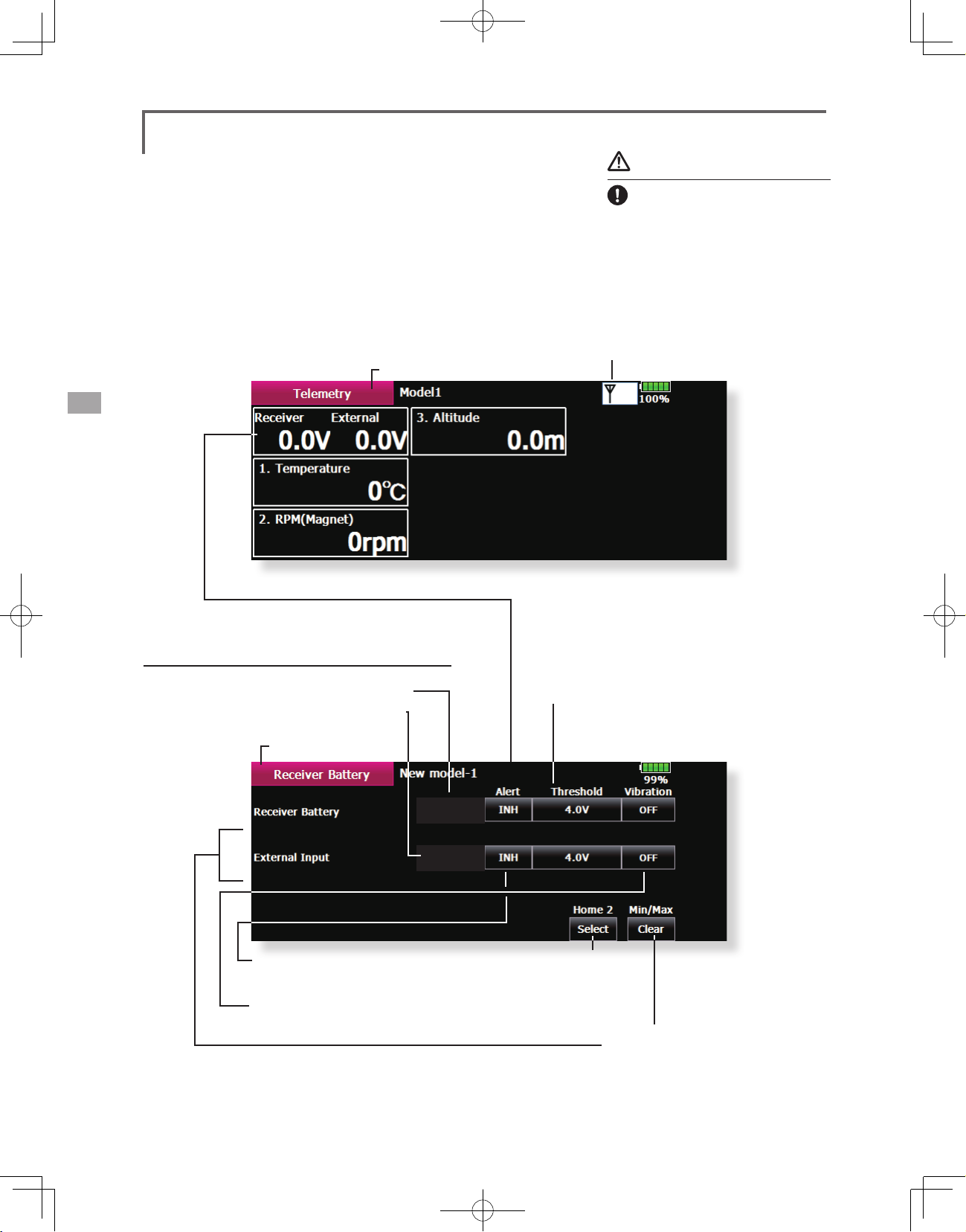
Telemetry
Displaying data from the receiver
This screen displays your choice of data from the
receiver.
Also warnings can be activated regarding the
data. For example, if the receiver voltage drops, the
user can be warned by an alarm.
● Call the following setting screen by pressing the
[Telemetry] button of the Linkage Menu.
●Return to Linkage Menu
Warning
Do not watch the transmitter
screen during ight.
*You may loose sight of the aircraft during
ight and this is extremely dangerous.
Have an assistant on hand to check the
screen for you. A pilot should NEVER
take his eyes off his aircraft.
●Receiving state (R7008SB → T18MZ)
Receiver Battery Display
● External Input voltage
Extra Voltage connector)
(
●Return to Telemetry
5.0V - 6.4V
0.0V - 0.0V
● Press to setup an alarm type alert.
● Press to setup vibration alerts.
4 types of vibration selections are possible.
● If voltage falls further than the voltage
set up here, the alarm will operate.
5.9V
0.0V
● It is selection of the
sensor displayed on
home 2 screen.
● Display of the maximum and
minimum ranges for voltage.
[Clear] To reset.
<Linkage Menu>
94
Page 95
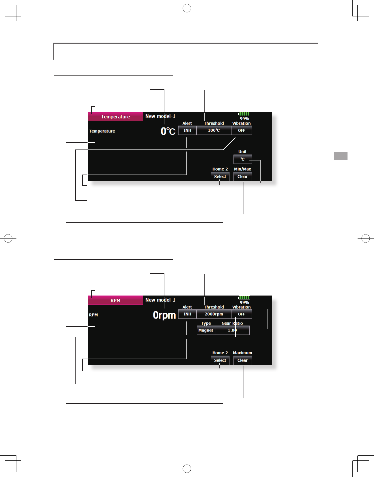
Temperature Display
● Temperature Display
●Return to Telemetry
● Press to setup an alarm type alert.
● Press to setup vibration alerts.
4 types of vibration selections are possible.
● It is selection of the
sensor displayed on
home 2 screen.
● If the temperature reaches higher than
the temperature set up here, the alarm
will operate.
● It is display change
from Centigrade
to Fahrenheit[
● Display of the maximum
and minimum ranges for
temperature.
[Clear] To reset.
[℃]
℉]
RPM Display
● RPM Display
●Return to Telemetry
● Press to setup an alarm type alert.
● Press to setup vibration alerts.
4 types of vibration selections are possible.
● It is selection of the
sensor displayed on
home 2 screen.
● If RPM goes higher than the RPM set
here, the alarm will operate.
● Select the
type:Either
optical sensor
or magnetic
sensor. In an
optical sensor,
the number of
fins is entered.
In an magnet
sensor, the gear
ratio is entered.
● Display of the maximum and
minimum ranges for RPM.
[Clear] To reset.
<Linkage Menu>
95
Page 96

Altitude Display
Atmospheric pressure is measured by a sensor. The
actual altitude is measured in regards to the difference
between the ground and atmospheric pressure.
Atmospheric pressure when the power supply
of the altitude sensor is set to ON is displayed as a
standard (0 m).
[Reset] Push the button to re-set to a standard
altitude.
● Variometer Display:How many meter rise (descent) in 1 second.
● Atmospheric pressure Display
● Altitude Display
●Return to Telemetry
What altitude is it?
● Press to setup an alarm type alert.
● If Altitude becomes higher than the
Altitude set here, the alarm will operate.
●Press to setup
vibration alerts.
4 types of
vibration
selections are
possible.
● If Preset is pushed, the present
atmospheric pressure = altitude
of 0 m.
Home2 Display
Three telemetry data can be displayed on Home2
screen. The item to display can be set up.
● It is displayed by [ON]
Undisplayed is carried out in [OFF.]
● It is selection of the
sensor displayed on
home 2 screen.
● Display of the maximum and
minimum ranges for Altitude.
[Clear] To reset.
● The slot number of the telemetry data displayed
on Home2 screen is set up.
<Linkage Menu>
96
Page 97

Sensor
Various telemetry sensors setting.
The telemetry sensor slot No. and which sensor
is used in each slot can be changed in this screen.
Since the sensor in each slot is determined at
initialization and the same slot No. is memorized
even for sensors sold separately, sensors can be
used by simply connecting them to S.BUS2. When
customizing the sensors yourself, perform the
settings in this screen.
*Three slots of altitude sensor are used.
● Touch the [Sensor] button in the Linkage Menu to
call the setup screen shown below.
●Return to Linkage Menu
[What is a slot?]
Servos are classified by CH, but sensors are
classified in units called “slot”. There are slots
from No. 1 to No. 31.
Altitude sensors and other data sensor units
may use multiple slots.
By the sensor which uses two or more slots,
the required number of slots is automatically
assigned by setting up a start slot.
When 2 or more of the same kind of sensor
are used, the sensors themselves must allocate
unused slots and memorize that slot.
Procedure for changing the sensor of each slot No.
1. Select [Sensor] from the Linkage Menu.
2. Select the sensor of the slot No. to be changed.
3. Select the type of displayed sensor.
4. When the [Yes] key is pressed, the type of sensor is
changed.
*In the case of a sensor which uses more than one slot, you may
be unable to reassign.
<Linkage Menu>
97
Page 98

Procedure for changing the slot No. of each sensor unit
1. Select [Sensor] on page 2 of the Linkage Menu.
2. Call page 2 by pressing [1/2] and press [Change Slot].
3. Connect the receiver battery and the sensor unit to the S.I/F
connector behind the rear cover of the transmitter using a 3-way
hub or 2-way cord.
4. Press the [Read] key. The current slot No. is displayed.
5. When a number is pressed, the [ △ ], [ ▽ ], [ △△ ] and [ ▽▽ ]
keys appear. Now change the desired No.
6. When the [Write] key is pressed, the desired No. is written to the
sensor
●Call this screen by switching to page 2 by
pressing the [1/2] button on the Sensor
screen and then pressing [Change Slot].
T18MZ
HUB
orY-adapter
Sensor
Receiverbattery
●When pressed, the current slot No. is
displayed.
●The slot No. is written to the sensor.
●Returns to the Sensor screen.
<Linkage Menu>
98
Page 99

Warning
Setting of warning sound and vibration
A warning upon powering up your transmitter
can be set up for the following functions.
Default setting is ON. Leave ON any function
in which it seems that you feel is dangerous upon
power up.
The alarm is stopped at power up if the function
is changed to OFF.
● Touch the [Warning] button in the Linkage Menu (2/2)
to call the setup screen shown below.
●Return to Linkage Menu
* If a throttle stick turns on a power power supply
at full throttle as in the case of the electric
craft, it may begin to turn to the prop at high
rotation suddenly, and this is very dangerous. We
recommend you set the throttle position warning
to ON.
●If this is turned On, the alarm will be a vibration in the
transmitter when you power on the radio.
●If this is changed to OFF, alarm will not sound
during powering up of your transmitter.
●If a throttle stick is above low throttle when you power on your
transmitter, the next screen will appear and an alarm will sound.
You should never power up your transmitter with the throttle stick above
fully closed for safety's sake.
●If you lower your throttle stick when you see this warning, the
conrmation screen will appear and ask if you would like to Transmit.
If you wish to transmit, press YES.
<Linkage Menu>
99
Page 100

Data Reset
Model memory setting data reset. (by item)
This function is designed to allow you to reset
selected portions or all of the settings saved in
the active model memory. You may individually
Model menu setting:
Resets all the functions in the Model Menu
except Condition Select.
choose to reset the following sets of data;
All model setting:
T1~T6, CD:
Reset the digital trim setting.
*All the conditions, or the condition currently being displayed
(the entire group for group setting), can be selected.
Direct key:
Resets direct key assignment.
● Touch the [Data Reset] button in the Linkage Menu
to call the setup screen shown below.
●Return to Linkage Menu
Date Reset
Function Name
Model 1 Condition 1
Direct Key Model Menu Setting All Model SettingT1~T6, CD
Resets all Linkage and Model Menu functions
except for System Type, Model Select, and Model
Type.
Function Name:
A function name is reset.
85%
Data Resetting
1. Touch the desired button to reset the data.
2.Perform the data reset according to the
<Linkage Menu>
100
Default setting of the motor channel will be
reversed once a reset is complete.
instructions displayed on a screen. When
complete, touch the Data Reset button to
exit.
 Loading...