

Page 1

WIRELESS DATA COMMUNICATION MODEM
FRH-SD07TU (US Version)
FRH-SD07TB (EU Version)
Ultra Low Power Consumption
Wireless Modem with Serial Interface
Instruction Manual
Futaba Corporation
Industrial Radio Control
Page 2

Page 3

Page i
I Notice
This device complies with part 15 of the FCC rules and with ETS 300 440 of the European
Telecommunication Standard Institute (ETSI). Operation is subject to the following two
conditions: (1) This device may not cause harmful interference, and (2) this device must
accept any interference received, including interference that may cause undesired operation.
This equipment has been tested and found to comply with the limits for a Class A digital
device, pursuant to part 15 of the FCC Rules. These limits are designed to provide reasonable
protection against harmful interference when the equipment is operated in a commercial
environment. This equipment generates, uses, and can radiate radio frequency energy and, if
not installed and used in accordance with the instruction manual, may cause harmful
interference to radio communications. Operation of this equipment in a residential area is
likely to cause harmful interference in which case the user will be required to correct the
interference at his own expense.
Any unauthorized changes or modifications to this device not expressly approved by Futaba
Corporation could void the user’s authority to operate the device and possibly result in
damage to the equipment and/or cause serious or fatal injuries to the operator or nearby
personnel.
This device is intended to be installed and used in accordance with the instructions contained
in this manual. Failure to comply with these instructions could void the user’s authority to
operate the device and possibly result in damage to the equipment and/or cause serious or
fatal injuries to the operator or nearby personnel.
[Especially for users in Europe]
FRH-SD07TB, European version can be used in the following countries: Austria, Belgium,
Denmark, Estonia, Finland, France, Germany, Greece, Iceland, Ireland, Italy, Luxembourg,
Norway, Portugal, Spain, Sweden, Switzerland, The Netherlands and United Kingdom (the
Czech Republic and Hungary with limitation, see below).
In France and Spain, usable frequency is limited by its country’s regulatory authority. See
p.35
FREQUENCY GROUPING for the frequency usage limitation.
Belgium does not authorize FRH-SD07TB itself. FRH-SD07TB must be fitted into the final
product, then tested to Radio, EMC and safety requirements. A notification will be only
accepted for the final product then.
Users in the Czech Republic and Hungary can use FRH-SD07TB modem, but it has some
limitation for operation. Please contact local regulatory authority to obtain details before
attempt to use FRH-SD07TB modem in that countries.
Futaba Corporation Rev. 050415-01.1
Page 4

Page ii FRH-SD07TU/TB Manual
II Important Safety Information
The list of dangers, warnings and cautions in this section contain important information that
will help ensure safe operation of the system. Please read carefully and understand all of
these items. All installers, operators and maintenance personnel should read and understand
this information before installation, use, or maintenance of the FRH-SD07TU/TB system.
The FRH-SD07TU/TB system by itself is not inherently dangerous. HOWEVER, WHEN
THE FRH-SD07TU/TB IS CONNECTED TO OTHER EQUIPMENT FOR THE
PURPOSE OF CONTROL, SAFETY AND ALL POSSIBLE ASSOCIATED
DANGERS MUST ALWAYS BE GIVEN THE UTMOST CONSIDERATION
DURING SYSTEM INTEGRATION, DESIGN, INSTALLATION, AND USE.
The FRH-SD07TU/TB system may be used in virtually unlimited applications. Many of
these associated systems can, by themselves, pose a mechanical, electrical or other hazard to
operators and other persons or equipment. To address all possible applications and associated
safety hazards in this manual would be impossible. The warnings below and throughout this
manual give information that will allow safe installation and use the modem system
applications. If you have questions regarding the safety of your specific application, please
contact the appropriate people for help. Your Futaba sales representative, representatives of
the equipment being controlled, and the technical support staff at local branch of Futaba
Corporation are among those who can provide assistance with your safety concerns.
The following warnings are included in the lists that follow but warrant repetition here:
In installations where the FRH-SD07TU/TB system is used to control motion or operation of
potentially dangerous equipment, it is imperative for safety that all operators and installers be
thoroughly trained in the normal function of that equipment before attempting to control it
remotely with the FRH-SD07TU/TB system.
To help ensure safe operation of the equipment, the FRH-SD07TU/TB system must be
connected so that it will operate in a fail-safe way. In other words, the equipment being
controlled should stop or return to its safest state in the absence of a control signal or total
loss of RF transmission from the FRH-SD07TU/TB system. Our system uses one of the most
reliable methods available to transmit data using radio signals. Many factors can affect a
radio signal that may block it or interfere enough to disrupt regular transmission. Because of
this, equipment motion or dangerous electrical current, for example, that continues during a
loss-of-signal condition could be very dangerous.
Rev. 050415-01.1
Page 5
Page iii
Four symbols are used in the margin of the following section and throughout the manual to
indicate the level of hazard or information listed.
The symbols are defined as follows:
Indicates a hazard that will cause severe personal injury, death, or
substantial property damage if the warning is ignored.
Indicates a hazard that can cause severe personal injury, death, or
substantial property damage if the warning is ignored.
Indicates a hazard that will or can cause minor personal injury, or
property damage if the warning is ignored.
Indicates installation, operation, or maintenance information that is
important but not hazard-related.
Please read the following safety information carefully. Some of these notices are duplicated
throughout the manual, in areas of associated content, for your benefit.
II.I General Safety Hazards and Notes
Improper installation and/or operation of the FRH-SD07TU/TB
system can cause serious or fatal injuries to the operator or nearby
persons and cause damage to the FRH-SD07TU/TB system, and any
equipment it is used to control. Please read and understand this manual
completely and the manual of all equipment being controlled before
attempting to operate or install this system.
Always keep this manual at a location readily accessible to anyone
operating the system and related equipment. Ensure that all operators
have read and understood this manual, especially all safety and
operation procedures contained in it. Please refer to the section in this
manual titled
How to Obtain Help for the contact that can supply
additional manuals or answers to questions not covered in this manual.
If this product is passed on to a different user, be sure that this manual
accompanies the product.
Futaba Corporation Rev. 050415-01.1
Page 6
Page iv FRH-SD07TU/TB Manual
Be certain that the installer of this equipment reads and understands
the instruction manual of the equipment that is being connecting to
before attempting this installation.
The FRH-SD07TU/TB modem should NOT be used in a manner in
which failure of the product or loss of the radio signal could cause
damage to the equipment being controlled, or to anything in the area in
which such equipment is located. All integrated control systems
should be designed for “fail-safe” operation so that a temporary or
permanent loss of signal will not endanger any person, critical process,
or equipment (refer to the beginning of the safety section for further
explanation). The system design should ensure that the equipment
being controlled will default to its safest state in the event of signal
loss.
The FRH-SD07TU/TB modem contains no user serviceable parts. If
the unit requires service, contact your sales representative or local
branch of Futaba Corporation per instructions the section titled
How
To Obtain Help. Do not disassemble or attempt to repair the FRH-
SD07TU/TB yourself. Doing so could void your warranty and may
void the user’s authority to operate the device.
Contact Futaba before using the FRH-SD07TU/TB modem in safety
critical applications such as medical equipment, aircraft, hazardous
materials handling, etc.
II.II Installation Safety Hazards and Notes
When mounting the FRH-SD07TU/TB modem, use M2 (ISO) screws
that project 2 to 3 mm into the modem. Screws that project further into
the modem (3.5mm MAX) may permanently damage the internal
components and/or cause the FRH-SD07TU/TB modem to
malfunction.
Use only the proper regulated DC voltage supplied to the FRHSD07TU/TB modem. Use of any other voltage may permanently
damage the modem and/or cause the modem to malfunction and create
a shock or fire hazard.
Be certain that all AC power outlets used the power adapters have
been properly installed, grounded, and fused. An electrical shock
Rev. 050415-01.1
Page 7

Page v
hazard may exist if this unit is powered by a faulty power outlet or
source. If such a situation is discovered, immediately discontinue use
until the power source and outlet have been properly installed,
grounded, and fused by an electrician or other authorized person.
Be sure to wire the power and serial connections correctly. Incorrect
wiring can damage the system, cause it to malfunction and/or create a
shock and fire hazard.
Ensure that the FRH-SD07TU/TB modem power and the power to the
equipment to be controlled is turned off before connecting or
disconnecting the cable between them. This will help prevent
accidental damage to the system and unexpected operation and/or
injury.
Be sure the FRH-SD07TU/TB modem power, the power to the
equipment that is being connecting to it, and the DC power source are
all turned off before wiring and connecting the power cable.
Be sure that the supplied power is within the specified range (2.7 to
3.3 VDC). Voltages outside the specified range may damage the FRHSD07TU/TB modem.
Be sure that the power source has sufficient current capacity.
Insufficient current may cause the unit to malfunction.
Securely attach the antenna cable, and serial communication connector
to the FRH-SD07TU/TB modem and equipment/power source to
which it is connected. Failure to do so could cause an unexpected
system failure.
II.III Antenna Installation Hazards and Notes
Be sure to keep all systems and antennas clear of power lines.
Permanent equipment damage and severe shock injury or death can
occur if the system contacts power lines.
Contact Futaba before connecting any antenna not provided by Futaba
specifically for the FRH-SD07TU/TB modem. Attaching any nonauthorized antenna may be in violation of FCC regulations.
Futaba Corporation Rev. 050415-01.1
Page 8
Page vi FRH-SD07TU/TB Manual
When using two antennas with a single FRH-SD07TU/TB modem for
diversity reception, mount the antennas as far apart as possible (6 cm
minimum). If the antennas are too close, the diversity advantage will
not be achieved.
Before each use, verify that the antenna (and antenna cable, if used) is
securely attached and in good condition. A loose antenna or cable may
severely reduce the operating range of the system.
When installing the FRH-SD07TU/TB modem in a mobile unit such
as an Automated Guided Vehicle (AGV), Futaba recommends to use
the diversity reception feature as a remedy for multipath fading
problems. For diversity reception, install the two antennas as far apart
as possible in order to gain maximum benefit (6 cm minimum).
The FRH-SD07TU/TB operates at frequencies in the 2.4 GHz band.
These frequencies are more directional than lower frequencies and are
easily reflected. If there are metal structures nearby, the effective
range may be shortened or the directional properties may be further
narrowed. To help avoid this, mount the antenna as far away as
possible from surrounding metallic structures.
Multipath problems occur easily at frequencies in the 2.4 GHz band.
When multipath problems are present, moving the antenna as little as
10 cm may result in improved communication or, conversely,
worsened or complete loss of communication. Futaba recommends
that the mounting position of the antenna be determined after testing
and verifying optimal communication conditions. Negative multipath
effects can also be overcome with antenna diversity. See p.12
DIVERSITY ANTENNA SETUP and the related register settings for more
details regarding antenna diversity function.
When installing multiple FRH-SD07TU/TB modem systems that will
use different frequency groups in the same area, modem’s antennas of
different frequency groups must be mounted at least 6 feet (2 meters)
apart. Failure to do so may severely reduce the modem operating range.
Please contact Futaba for information about antenna separation when
using the FRH-SD07TU/TB and other wireless products in the same
area.
Rev. 050415-01.1
Page 9

Page vii
II.IV Environmental Safety Hazards and Notes
If the FRH-SD07TB/TU modem has been stored at a temperature
beyond the specified operating temperature range for the system, it
may not function properly. Allow it to return to normal temperatures
before use. Refer to APPENDIX A – TECHNICAL SPECIFICATIONS for
the actual operating temperature range.
The FRH-SD07TB/TU modem is a precision electronic device with a
rugged design that is intended for industrial applications. However, do
not install it where it will encounter excessive vibrations. In some
cases, isolation mounts may be used to isolate the modem from the
equipment’s vibration. Excessive vibration can permanently damage
the modem and/or cause it to malfunction.
Do not operate the FRH-SD07TB/TU modem in environments where
it will be subjected to excessive moisture (such as rain or water spray),
dust, oil, or other foreign matter (such as metal particles). Doing so
may permanently damage the modem and/or cause it to malfunction. If
it does become wet or contaminated, correct the situation, verify
proper operation and have any problems corrected before using it to
control other equipment. If necessary, the modem can be mounted
inside a protective or waterproof enclosure. If the enclosure is metallic,
the antenna must be mounted externally or the effective operating
range will be severely limited.
The FRH-SD07TU/TB is designed for indoor use. When using it
outdoors, the modem should be mounted in a waterproof enclosure
and the ambient temperature range should be checked to insure that it
is within the modem’s specifications. Always use the modem within
its specified environmental ranges.
II.V Other Notice
Italicized gothic word used in this manual shows functional and
technical term especially important for the FRH-SD07TU/TB modem.
Futaba Corporation Rev. 050415-01.1
Page 10

Page viii FRH-SD07TU/TB Manual
Caution
Exposure to Radio Frequency Radiation
For FCC RF safety requirements a miminmum of 20 cm separation
distance should be kept between the antenna and the user.
Operational Safety Hazards and Notes
Before each use of the FRH-SD07TU/TB modem, ensure that the area
where the equipment will be operated is clear of people or obstacles
that may affect its safe operation.
Before each use of the FRH-SD07TB/TU modem, verify that both the
equipment being controlled and the modem are in proper operating
condition.
When rewriting the FRH-SD07TB/TU modem’s memory registers, do
not turn the modem’s power off until the modem returns a “P0”
response. If the power is interrupted before a P0 response is returned,
the memory contents may be lost or corrupted and the modem
operation will be unpredictable. If the memory contents are lost or
corrupted, they may be restored to original default settings by
reinitializing them. (See p.44 Memory R
EGISTER INITIALIZATION
for
more details.)
Do not attempt to operate remotely controlled equipment outside the
communication range of the FRH-SD07TU/TB system. Doing so
could cause loss of control of the equipment.
Without implementing proper serial communication flow control
settings, the baud rate between the modem and its terminal equipment
(wire linked) can exceed the wireless link data rate and cause the
modem buffer to overflow. This can result in malfunction of the
systems being controlled and/or data corruption. Ensure that the
appropriate flow control settings are being used for your upper layer
application protocol.
Rev. 020510-01
Page 11

Page ix
III System Identification
For future reference, please take a moment to fill in the information below. This information
will help us respond as quickly as possible should your FRH-SD07TU/TB modem ever need
repair or replacement.
Model Name and Number:
FRH-SD07TU or FRH-SD07TB
Serial Number:
Date of Purchase:
Distributor Name:
Distributor Address:
Distributor Phone Number:
Futaba Corporation Rev. 050415-01.1
Page 12

Page x FRH-SD07TU/TB Manual
IV Limited Warranty
FUTABA WARRANTS ONLY THAT THE INDUSTRIAL RADIO CONTROL SYSTEM
GOODS OR PRODUCTS FURNISHED HEREWITH SHALL BE FREE FROM DEFECTS
IN MATERIAL AND WORKMANSHIP UNDER NORMAL CONDITIONS OF USE AND
SERVICE FOR A PERIOD OF ONE (1) YEAR FROM THE DATE OF SALE TO THE
PURCHASER WHO IS THE FIRST BUYER OF THE GOODS FOR USE OR
CONSUMPTION AND NOT FOR RESALE OTHER THAN AS A COMPONENT OF
ANOTHER PRODUCT MANUFACTURED FOR SALE BY SUCH PURCHASER
(“CONSUMER”). FUTABA’S LIABILITY, WHETHER BASED ON BREACH OF
WARRANTY OR NEGLIGENCE, SHALL BE LIMITED, AT FUTABA’S ELECTION,
TO REPLACEMENT OR REPAIR OF ANY SUCH NONCONFORMING GOODS, F.O.B.
FUTABA’S U.S.A. PLANT, OR, AT FUTABA’S ELECTION, CREDIT FOR THE NET
PURCHASE PRICE OF SUCH GOODS. ALL CLAIMS HEREUNDER MUST BE MADE
IN WRITING DURING THE WARRANTY PERIOD, AND FUTABA SHALL HAVE
THE RIGHT PRIOR TO ANY RETURN OF GOODS TO INSPECT ANY GOODS
CLAIMED TO BE NONCONFORMING, AND IN ANY EVENT RESERVES THE
RIGHT TO REJECT CLAIMS NOT COVERED BY WARRANTY. THIS LIMITED
WARRANTY CONSTITUTES FUTABA’S SOLE WARRANTY. FUTABA MAKES NO
OTHER WARRANTY OF ANY KIND, EXPRESS OR IMPLIED, AND EXPRESSLY
DISCLAIMS ANY IMPLIED WARRANTY OF MERCHANTABILITY OR FITNESS
FOR A PARTICULAR PURPOSE. FUTABA’S WARRANTY SHALL NOT APPLY IF,
AMONG OTHER LIMITATIONS CONTAINED HEREIN OR FURNISHED WITH THE
PRODUCT, BUYER, OR CONSUMER, OR ANY USER OF THE PRODUCT (A)
ALTERS SUCH PRODUCT, OR (B) REPLACES ANY PART OF SUCH PRODUCT
WITH ANY PART OR PARTS NOT FURNISHED BY FUTABA FOR THAT PURPOSE,
OR IF, AMONG SUCH OTHER LIMITATIONS, PRODUCT FAILS TO OPERATE
PROPERLY OR IS DAMAGED DUE TO ATTACHMENTS OR COMPONENTS THAT
ARE NOT FURNISHED BY FUTABA FOR USE WITH OR REPAIR OF THE PRODUCT
UNLESS SUCH USE IS AUTHORIZED IN WRITING IN ADVANCE BY FUTABA.
THIS LIMITED WARRANTY EXTENDS ONLY TO THE CONSUMER AND IS NOT
ASSIGNABLE OR TRANSFERABLE. This limited warranty shall not apply to fuses, lamps,
batteries, or other items that are expendable by nature, unless otherwise expressly provided.
This limited warranty does not cover any defect or damage to any of the goods caused by or
attributable to force, accident, misuse, abuse, faulty installation, improper maintenance,
improper electrical current, failure to install or operate in accordance with Futaba’s written
instructions, repair or alteration by unauthorized persons, or leaking batteries. THE GOODS
ARE SENSITIVE ELECTRONIC DEVICES REQUIRING SPECIAL HANDLING,
AND THIS LIMITED WARRANTY DOES NOT APPLY TO PRODUCTS NOT
HANDLED IN ACCORDANCE WITH INSTRUCTIONS SET FORTH IN THE
MANUAL.
Rev. 050415-01.1
Page 13

Page xi
THIS LIMITED WARRANTY DOES NOT COVER INDUSTRIAL RADIO
CONTROL PRODUCTS PURCHASED OR USED OUTSIDE OF THE UNITED
STATES WITHOUT FUTABA’S PRIOR APPROVAL.
V
Returns
Futaba’s authorization must be obtained prior to return of any item for warranty or other
repair or replacement or credit and will reflect Futaba’s warranty service procedure.
Consumer’s warranty rights are governed by the terms of Futaba’s Limited Warranty, as
above described. Products returned for warranty repair or replacement or credit must be
carefully and securely packed for return, preferably in the original carton or equivalent. The
Consumer must also include in the carton a legible copy of the bill of sale or invoice which
shows the date of sale and the original Buyer’s and Consumer’s names, and also a letter
which gives the Consumer’s return address and contact telephone number, the model and
serial numbers of the product(s) returned, and a brief explanation of the problem or claimed
defect. Any returned products that are replaced by Futaba shall become the property of
Futaba. If after inspection Futaba determines the defect is not covered by its limited warranty,
Futaba will notify Consumer of its determination and will not undertake any repairs or
product replacement until Consumer agrees to pay for all necessary parts and materials, labor
(to be charged at Futaba’s standard repair rate then in effect), and other expenses including
all shipping charges and insurance. Futaba reserves the right to retain possession of any
product returned by Consumer because of defects not covered by Futaba’s warranty until
Futaba receives Consumer’s agreement as above noted or, if Consumer wants the product
returned without repair or replacement, Consumer reimburses Futaba for all shipping and
handling charges incurred by Futaba. Issuance of credit for returned items shall be made at
Futaba’s unfettered discretion. Consumer will not be entitled to return defective goods for
cash refunds. Consumer must inspect goods immediately and no rejection or revocation of
acceptance shall be permitted more than ten (10) days after delivery to, or first use by,
Consumer of the goods, whichever occurs first.
VI
Patents – Copyrights – Trademarks – Proprietary Rights
If this product was manufactured according to designs or processes specified by Consumer,
Consumer shall indemnify and save Futaba, its affiliates, officers, agents, and employees,
harmless from any expense, loss, attorneys’ fees, costs, damages, or liability which may be
incurred as a result of actual or alleged infringement of patent, copyright, or trademark rights.
Furnishing of these products does not convey a license, implied or otherwise, under any
patent, copyright, or trademark right in which Futaba has an interest, nor does it convey
rights to trade secrets or any other proprietary information of Futaba.
VII
Limitation of Damages and Action
IN NO EVENT SHALL FUTABA BE LIABLE TO CONSUMER, OR ANY OTHER
PERSON FOR ANY INCIDENTAL, CONSEQUENTIAL, OR SPECIAL DAMAGES
RESULTING FROM THE USE OF OR INABILITY TO USE THIS PRODUCT,
Futaba Corporation Rev. 050415-01.1
Page 14

Page xii FRH-SD07TU/TB Manual
WHETHER ARISING FROM BREACH OF WARRANTY OR NEGLIGENCE OF
FUTABA, OR OTHERWISE. Any action hereunder must be commenced within one (1)
year of accrual of cause of action or be barred and forever waived. No modification or
alteration of Futaba’s Limited Warranty or any other provision of this paragraph or the above
paragraphs shall result from Futaba’s acknowledgment of any purchase order, shipment of
goods, or other affirmative action by Futaba toward performance following receipt of any
purchase order, shipping order, or other form containing provisions, terms, or conditions in
addition to or in conflict or inconsistent with any such provisions.
Rev. 050415-01.1
Page 15

Page xiii
TABLE OF CONTENTS
INTRODUCTION........................................................................................................1
1.1 SPECIAL FEATURES....................................................................................................................2
1.2 HOW TO OBTAIN HELP ...............................................................................................................3
1.3 STARTER KIT .............................................................................................................................4
1.4 OPTIONAL PARTS ....................................................................................................................... 4
1.5 PHYSICAL DESCRIPTION.............................................................................................................5
2 SYSTEM INSTALLATION...................................................................................7
2.1 WIRELESS MODEM INSTALLATION ...............................................................................................8
2.2 COMMUNICATION CABLE CONNECTION........................................................................................9
2.3 POWER SUPPLY PRECAUTIONS................................................................................................. 10
2.4 ANTENNA CONNECTION............................................................................................................11
2.5 OTHER INSTALLATION PRECAUTIONS ........................................................................................12
3 SYSTEM OPERATION......................................................................................17
3.1 OPERATION MODES ................................................................................................................. 18
3.2 PACKET TRANSMISSION MODE..................................................................................................20
3.3 POWER DOWN MODE...............................................................................................................33
3.4 FREQUENCY GROUPING ...........................................................................................................35
4 FUNCTION CONTROL METHODS...................................................................41
4.1 FUNCTION CONTROL METHODS ................................................................................................42
4.2 COMMUNICATION METHODS .....................................................................................................47
5 MEMORY REGISTER DESCRIPTION..............................................................59
5.1 MEMORY REGISTER DESCRIPTION............................................................................................60
6 COMMAND SET DESCRIPTION.......................................................................79
6.1 COMMAND SET DESCRIPTION...................................................................................................80
7 ADVANCED APPLICATIONS.........................................................................117
7.1 HEADERLESS PACKET TRANSMISSION MODE...........................................................................118
7.2 DIRECT TRANSMISSION MODE ................................................................................................127
7.3 ULTRA MODE.......................................................................................................................135
8 APPENDIX.......................................................................................................143
8.1 INTERFACE ............................................................................................................................144
8.2 CONVERSION CIRCUIT............................................................................................................148
8.3 SPECIFICATION OF THE CONNECTORS.....................................................................................150
8.4 AUXILIARY INTERFACE............................................................................................................151
8.5 PREVENTING UNDESIRED RADIO CONNECTION........................................................................ 157
8.6 OPERATION IMPORTANT NOTICE...................................................................................158
8.7 Q & A ...................................................................................................................................161
8.8 TROUBLESHOOTING ...............................................................................................................163
8.9 SPECIFICATION ......................................................................................................................165
8.10 DIMENSIONS.......................................................................................................................167
8.11 GLOSSARY OF TERMS.........................................................................................................173
Futaba Corporation Rev. 050415-01.1
Page 16

Page xiv FRH-SD07TU/TB Manual
Rev. 050415-01.1
Page 17

Page 1
SECTION
INTRODUCTION
1
CONTENTS
INTRODUCTION.......................................................................................................1
1.1 SPECIAL FEATURES............................................................................................................................ 2
1.2 HOW TO OBTAIN HELP .......................................................................................................................3
1.3 STARTER KIT......................................................................................................................................4
1.4 OPTIONAL PARTS...............................................................................................................................4
1.5 PHYSICAL DESCRIPTION ..................................................................................................................... 5
Futaba Corporation Rev. 050415-01.1
Page 18

Page 2 FRH-SD07TU/TB Manual
1.1 Special Features
The following list highlights some of the special features of the FRH-SD07TU/TB. For more
complete system specifications please refer to p.165
SPECIFICATIONS.
• Approved under FCC Part 15.247 rules (TU version) and under the European ETS 300 440
standard (TB version) -- no special user license required
• Operating range greater than 1000 feet, line-of-sight -- configurable as a repeater for
extended range of application service area
• Ultra low power consumption. 35mA (Maximum) is achieved at the full-rate operation mode
retaining almost same function and performance in the conventional FRH series radio.
• Newly developed doze waiting reception, ULTRA (Ultra Low-power Transient Radio
Access) mode is implemented to the modem. It enables 2mA current consumption
(average) in the mode.
• 2.4 GHz Direct Sequence Spread Spectrum (DSSS) communication system provides
unsurpassed immunity to interference and RF noise
• Diversity receiving function is employed, which is practically invulnerable to multipath
fading
• Fast switching Time-Division-Duplex (TDD) provides virtual full-duplex communication
between terminal equipments at rates up to 115.2 kbps
• 54 user selectable frequencies allow up to 54 independent networks to operate
simultaneously in the same area
• Single fixed frequency communication or multi-access communication (automatic selection
of an vacant frequency from a defined group of frequencies) allows the user to select the best
frequency use for the application
• Supports 1:1, 1:n, and n:m wireless network topology
• Serial communication interface allows direct connection to a micro controller chip. By
converting its level by the external interface circuit, conformable to RS232C, RS422 and
RS485
• Small size allows easy integration with many systems (1.97" x 1.18" x 0.31" / 50 x 30 x 8
mm)
• Supply voltage range is DC voltage in 2.7 to 3.3 V DC
• Communication can be made with other FRH series modems such as 03TU, 04TU and 06TU.
Rev. 050415-01.1
Page 19

Page 3
1.2 How To Obtain Help
Please contact your local sales representative or local branch of Futaba Corporation at the address
shown below for help with the following:
• Application information regarding the FRH-SD07TU/TB or other Futaba products
• Technical assistance or training
• Answers to safety questions and issues
• Additional manuals or other documentation
• Repair or service
• Comments regarding the product or this manual
Japan
Futaba Corporation
Radio Control Equipment Group
1080 Yabutsuka, Chosei,
Chiba, 299-4395 JAPAN
Tel: +81 (475) 32-6173, Fax: +81(475) 32-6179
Internet: www.futaba.co.jp
United States
Futaba Corporation of America
Industrial Radio Control Department
1605 Penny Lane
Schaumburg, IL 60173
Tel: +1(847) 884-1444, Fax: +1(847) 884-1635
Internet: www.futaba.com
Europe
PENDING
When requesting repairs, please provide as much detail as possible regarding the failure and its
cause or symptoms. Doing so will help our service department find the problem quickly, resulting
in a shorter repair time.
CAUTION
The FRH-SD07TU/TB modem contains no user serviceable parts. If the
unit requires service, contact your sales representative or local branch of
Futaba Corporation as per instructed in this section. Do not disassemble or
attempt to repair the modem yourself. Doing so could void your warranty
and may void the user’s authority to operate the device.
Futaba Corporation Rev. 050415-01.1
Page 20

Page 4 FRH-SD07TU/TB Manual
1.3 Starter Kit
The FRH-SD07TU/TB sales policy is a bulk shipment. However, we prepared the starter kit for
an engineering evaluation and test. Below is the content of the starter kit. A content of the kit is
subject to change without notice.
Part Description Part Number Quantity
FRH-SD07TU Wireless Modem FRHSD07T02 1
or
FRH-SD07TB Wireless Modem FRHSD07T03 1
RS232C Interface Board 1
Communication Cable 1M38A14901 1
Simple Flat Antenna 1M38A15001 1
Startup Floppy Disk 1
1.4 Optional Parts
In addition to the basic system, the following accessories are available (Please refer to APPENDIX
A and B
for more detailed information).
Description Part Number
Communication Cable 1M38A14901
Simple Flat Antenna 1M38A15001
Pencil type Antenna 1M38A03301
Pedestal Base Antenna with flexible antenna element 1M38A14401
Pedestal Base Antenna w/ rigid antenna
element (outside use) 1M38A15402
Patch Antenna with Diversity Reception 00301319
Patch Antenna w/o Diversity Reception 00301328
U-FL to SMA Conversion Cable 1M38A14801
For information on obtaining spare parts or accessories, contact your local branch of Futaba
Corporation or the distributor from whom the system was purchased.
Rev. 050415-01.1
Page 21

Page 5
1.5 Physical Description
Please review the following section and take a moment to familiarize yourself with the FRHSD07TU/TB wireless modem.
AUX Terminal
Antenna Terminal A
Serial
Communication
Connector
Antenna Terminal B
Mounting Hole
Figure 1–1: Upper View (TU example)
Bottom Mounting Hole
Figure 1–2: Bottom View
(1) Serial Communication Connector
This is a connector to communicate to external terminal equipment (DTE; Data Terminal
Equipment) and connect serial communication cable. Also controlling functions such as
dwa pins are available. Signal is CMOS level. Add
har re reset and RS232C/RS485 selecting
leve nversion circuit whenl co level conversion is required.
(2) Antenna Terminal A
Con t Antenna. Install antennanec s provided by Futaba. If you install single antenna, Antenna
should be installed to this Terminal A.
) Antenna Terminal B
(3
This terminal is for diversity reception
function. Install second antenna to the terminal B.
(4) AUX Interface Terminal
This terminal is used as auxiliary for the operation. Monitoring statuses such as internal operatio
transmission/receiving operation and antenna diversity switching are available.
n,
Futaba Corporation Rev. 050415-01.1
Page 22

Page 6 FRH-SD07TU/TB Manual
(5) Mounting Hole
The holes are used to install the
modem to mounting terminal or bracket. Since screw can be
installed from the front surface, it is easy to install the modem. However, only two holes are
available, it should be fixed by guide structure on the other side of the unit to prevent vibration
problem.
) Bottom Mounting Hole
(6
The four holes are used to install the modem. Please use this holes instead of above explained
holes if tightened mounting is required. The hole has M2 taps. Use M2 (ISO) screws that project 2
to 3 mm into the modem. 3.5mm is MAXIMUM LIMIT. Screwing torque is 2.5 kg cm
MAXIMUM.
Rev. 050415-01.1
Page 23

Page 7
SECTION
2
SYSTEM INSTALLATION
2
CONTENTS
2 SYSTEM INSTALLATION...................................................................................7
2.1 WIRELESS MODEM INSTALLATION ...............................................................................................8
2.1.1 Mounting Method 1........................................................................................................... 8
2.1.2 Mounting Method 2........................................................................................................... 8
2.2 COMMUNICATION CABLE CONNECTION........................................................................................9
2.3 POWER SUPPLY PRECAUTIONS................................................................................................. 10
2.4 ANTENNA CONNECTION............................................................................................................11
2.4.1 Single Antenna Setup.....................................................................................................11
2.4.2 Diversity Antenna Setup.................................................................................................12
2.5 OTHER INSTALLATION PRECAUTIONS ........................................................................................12
2.5.1 Modem Installation Precautions.....................................................................................12
2.5.2 Antenna Installation Precautions.................................................................................... 13
2.5.3 Multiple FRH Modems Installation Precautions .............................................................14
Futaba Corporation Rev. 050415-01.1
Page 24
Page 8 FRH-SD07TU/TB Manual
2.1 Wireless Modem Installation
2.1.1 Mounting Method 1
A method to mount the modem directly on a surface using the mounting holes at the side of
the modem’s print circuit board. When using this method, provide a guide on the opposite
side, because two holes are not sufficient to securely mount the modem.
Guide
M2 Screw
S
pacer
Figure 2–1: Mounting Method 1
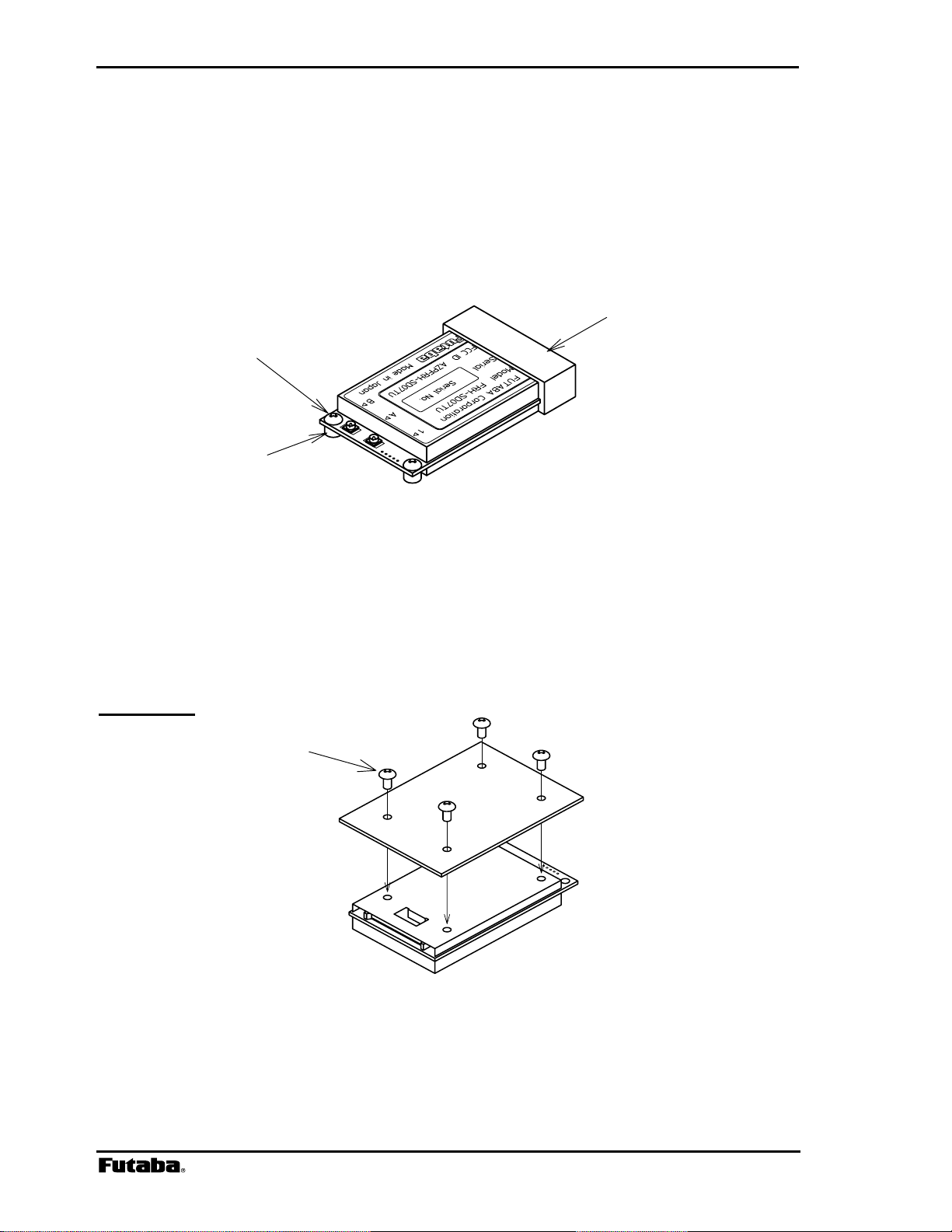
2.1.2 Mounting Method 2
To mount the modem using the holes on a flat horizontal surface, which are 3.5mm deep for
M2 screws. When using this method, use M2 screws which project the hole 2 to 3mm deep.
The screw tightening torque is below 2.5kg cm. Mount the modem on a flat plane and be
careful that there is no torsion applied. For the position of the mounting holes, see p.167
DIMENSIONS.
M2 Screw
Figure 2–2: Mounting Method 2
Rev. 050415-01.1
Page 25
Page 9
WARNING
WARNING
WARNING
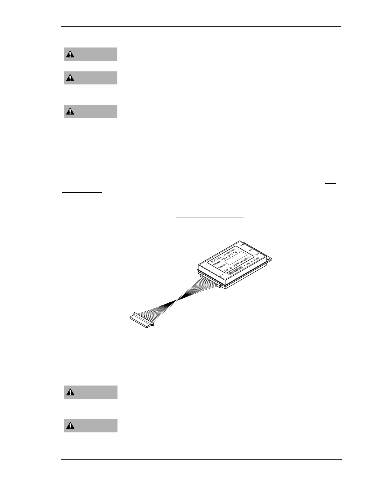
.2 Communication Cable Connection
2
Use the serial communication cable prepared by Futaba to connect the FRH-SD07TU/TB
modem to the exter , see p.144
ASSIGNMENT.
The signal level of the FRH-SD07TU/TB is CMOS. If the interface of the equipment to be
connected is RS232C or RS485, the level conversion circuit is required. For the example of
the level conversion circuit, see p.148
Be careful not to allow water, oil, dust and other foreign particles
(especially metal particles) to enter inside, which may damage the unit.
Since the FRH-SD07TU/TB modem is a precision electronic device,
install it at a place free of exces
unit from damage.
The FRH-SD07TU/TB is designed to be used inside the room. In case
of using it outdoor, be sure to use it within the extent limited by the
environmental specification, and check the ambient temperature and
the state of water-proof.
nal terminal equipment. For the connection of the modem
CONVERSION CIRCUIT.
sive shock and vibration to prevent the
PIN
gure 2–3: Connection of Communication Cable Fi
WARNING
WARNING
Futaba Corporation Rev. 050415-01.1
Be certain that the in
instruction manual of the equipm
attempting this installation.
Ensure that the FRH-SD07TU/TB modem power and the power to t
equipment to be controlled is turned off before connecting or
disconnecting the cable between them. This will help prevent
staller of this equipment reads and understands the
ent that is being connected to before
he
Page 26

Page 10 FRH-SD07TU/TB Manual
accidental damage to the system and unexpected operation and/or
injury.
CAUTION
WARNING
Computer) and PLC (Programmable Logic Controller) to be connected.
Be sure to wi
re the cable connections correctly. Incorrect wiring can
damage the system, causing it to malfunction and/or create a shock and
fire hazard. Also insert the cable firmly to the connector. Since no
system is pro
vided with the connector of this equipment, never stretch
lock
the cable or pull it up by hands.
In addition to this manual, read the operation manual of a PC (Personal
2.3 Power Supply Precautions
Since FRH-SD07TU/TB contains a very-high-frequency sensitive analog circuit, the modem
is susceptible to be affected the variation of the power source and noises from the digital
ci
rcuit. Therefore, when embedding the modem into the system, it is necessary to supply
pow
er to the modem from a different (independent) power supply IC chip other than those
used the power source line is enough below
in the digital circuits. Check the noise level from
than the practical level in the following way.
• Prepare 2 units of FRH-SD07TU/
y to the same and fixed frequency as below.
of each modem• Set the frequenc
TB mounted in the system
Example: @FRQ:H00 CR/LF
• Set the number of retransmission count of the modem on the sender side to 0.
Example: @RNO000 CR/LF
• Issue the @TXT command s
(communication success), there is no problem
• If “N1” response (communication failure) returns many times, there may
everal hundreds times. If almost all responses are “P0”
.
be a noise
problem in the power source.
• However, there is a possibility of causing communication failure due to a trouble in the
radio commun
repeat the above c
ica ed to
tion channel (multipath). For correct judgment, it is recommend
hecking several times.
For the operation of commands explained, refer p.79 COMMAND S
DESCRIPTION.
ET
Rev. 050415-01.1
Page 27
Page 11
2.4 Antenna Con
At least one antenn
modem in use. In the en ent where multipath fading exists with reliable
nection
a m
ust be connected to Antenna Connector A on each FRH-SD07TU/TB
vironm
communication requirements, a second antenna can be installed to Antenna Connector B for
the diversity reception function to
improve reception performance.
Be sure to keep all systems and antennas clear of power lines.
WARNING
Permanent equipment damage and severe shock injury or death ca
occur if the syst
em contacts power lines.
n
Please contact Futaba before attempting to install any third party
antenna equipment.
Please contact Futaba for information about antenna separation when
using the FRH-SD07TU/TB and other wireless products in the same
area.
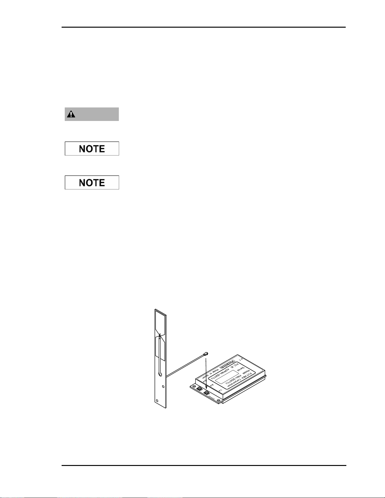
2.4.1 Single Antenna Setup
Always use Antenna Connector A when installing a single antenna. Antenna Connector B
cannot be used to transmit and is only used to attach a second receive antenna when the
antenna diversity function is enabled.
Refer to the figures below for details about the actual mounting and connecting methods.
Figure 2–5: Connecting the Antenna
Futaba Corporation Rev. 050415-01.1
Page 28
Page 12 FRH-SD07TU/TB Manual
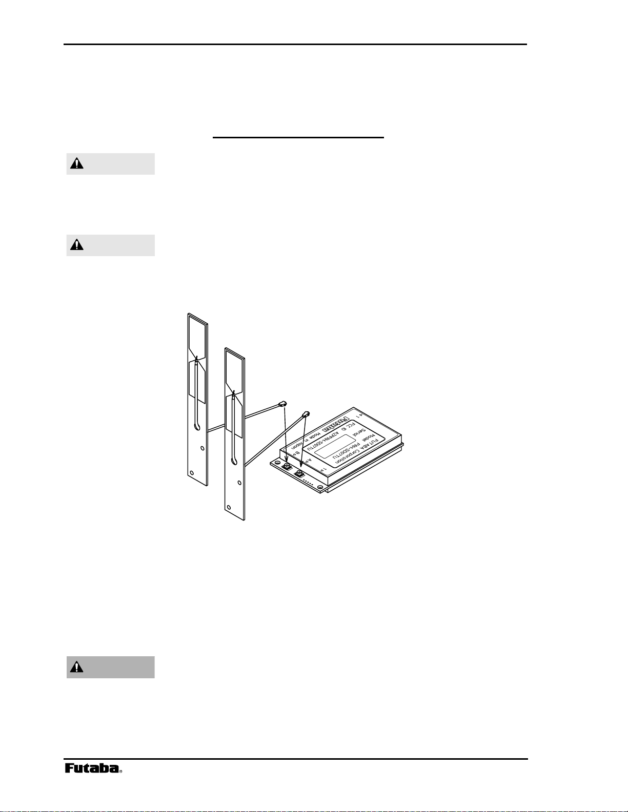
2.4.2 Diversity Antenna Setup
In certain situations, rece d antenna diversity
feature. This is accomplished by usin g the diversity
function in REG19 (see p.59
CAUTION
ption can be improved by using the integrate
g two separate antennas and enablin
MEMORY REGISTER DESCRIPTION
When using two antennas
with a single modem for diversity
).
reception, mount the antennas as far apart as possible (at least 6 cm).
If the antennas are too clos
e, the diversity advantage will not be
achieved.
CAUTION
Refer to the figures below for details about ounting and connecting methods.
Before connecting the connector, make sure that no dirt and foreign
particles are attached.
the actual m
Figure 2–6: Connecting Two Antennas
2.5 Other Instal
2.5.1 Modem Inst
WARNING
lation Precautions
allation Precautions
Securely attach the antenna cable, and serial communication
r connector to the FRH-SD07TU/TB modem and equipment/powe
source to which it is connected. Failure to not do so could cause an
unexpected system failure.
Rev. 050415-01.1
Page 29

Page 13
WARNING
WARNING
WARNING
The FRH-SD07TU/TB modem is a precision electronic device. Its
rugged design is intended for industrial applications. However, do not
install it where it will encounter excessive vibrations. In some cases,
isolation mounts may be used to isolate the modem from the
equipment vibration. Exces
the modem and/or cause it to malfunction.
If the FRH-SD07TU/TB modem has been stored at a temperature
beyond the specified operating temperature range fo
may not function properly. Allow it to return to normal temperatures
before use. Refer to p.165
temperature range.
Do not operate the FRH-SD07TU/TB modem in environments where
it will be subjected to excessive moisture (such as rain or water spray)
dust, oil or other foreign matter (such as metal particles). Doing so
may permanently damage the modem and/or cause it to malfunction.
it does become wet or contaminated, correct the situation, verify
proper operation and have any problems corrected before us
control other equipment. If necessary, the
inside a protective or waterproof enclosure. If the enclosure is metallic,
the antenna must be mounted externally or the effective operating
range will be severely limited.
sive vibration could permanently damage
r the system, it
SPECIFICATION for the actual operating
,
If
ing it to
modem can be mounted
WARNING
2.5.2 Antenna Ins
WARNING
WARNING
The FRH-SD07TU/TB is designed for indoor use. When using
outdoors, the
and the ambient temperature range should be checked to insure that it
is within the modem’s specifications. Always use the modem within
its specified environmental ranges.
tallation Precautions
Before each use, verify that the antenna (and an
securely attached and in good condition. A loose antenna or cable may
severely reduce the operating range of the system.
Avoid mounting the antenna near large metallic objects or inside metal
enclosures. Such objects can severely reduce the operating range of
the system.
When installing the FRH-SD07TU/TB modem in a mobile unit such
as an Automated Guided Vehicle (AG
modem should be mounted in a waterproof enclosure
tenna cable, if used) is
V), Futaba recommends using
it
Futaba Corporation Rev. 050415-01.1
Page 30

Page 14 FRH-SD07TU/TB Manual
the diversity reception feature as a remedy for to multipath fading
problems. For diversity reception, install the two antennas as far
apart as possible in order to gain maximum benefit (Actual
recommendation is 30 cm, 6 cm at least).
CAUTION
CAUTION
CAUTION
FUTABA standard antenna is made by Printed Circuit Board. It
fabricated for sev
force (bent or broken). Mount the antenna in a location where it will
be least likely to be damaged by contact with other objects or
equipment.
The FRH-SD07TU/TB operates at frequencies in the 2.4 GHz band.
hese frequencies are much directional than lower frequencies and are
T
asily reflected. If there are metal structures nearby, the effective
e
range may be shortened or the directional properties may be further
narrowed. To help avoid this
possible from surrounding m
Multipath problems occur easily at 2.4 GHz frequencies. When
multipath probl
y result in improved communication or, conversely, a further
ma
diminished or total loss of communication. Futaba recommends that
the mounting position of the antenna be determined after testing
verifying optimal communication conditions. Negative multipath
effects can also be overcome with antenna diversity. See p.12
DIVERSITY ANTENNA SETUP and the related register settings for more
details regarding antenna diversity.
ere use. Please use antenna without any unexpected
, mount the antenna as far away as
etallic structures.
ems are present, moving the antenna as little as 10 cm
is not
and
2.5.3 Multiple FRH
CAUTION
Rev. 050415-01.1
Modems Installation Precautions
When installing multiple FRH (series) modem systems that will use
different frequency groups in the same area, modem’s antennas of
different frequency groups
meters) apart. Failure to do so may severely reduce the modem
operating range.
Please contact Futaba for information about antenna separation when
using the FRH-SD07TU/TB and other wireless products in the same
area.
must be mounted at least 6 feet (2
Page 31

Page 15
2.5.4 ID Code Setting Recommendation
Futaba recommend user to set unique ID code to prevent unexpected
interference (jamming) between individual FRH systems working in
the same area.
The protocol on RF channel employed in FRH series modem is
Futaba’s original protocol. Therefore, there is no concern undesired
connection to other radio systems, such as wireless LAN. On the other
hand, it has a possibility that unexpected, undesired radio connection
between Futaba’s FRH series modems which work as different radio
systems.
To prevent this undesired radio connection, ID code (REG04 and
REG05) can be used. Since the FRH radio modems which set different
ID code can not communicate each other, it is possible to prevent an
undesired connection.
Set same ID code to the modems work in the same radio system. Set
appropriate and individual ID code for the system, do not use simple
code such as 1111H, not to coincide to other system’s setting.
Refer to p.157
manual for details.
PREVENTING UNDESIRED RADIO CONNECTION in this
Futaba Corporation Rev. 050415-01.1
Page 32

Page 33

Page 17
SECTION
3
SYSTEM OPERATION
3
CONTENTS
3 SYSTEM OPERATION......................................................................................17
3.1 OPERATION MODES ................................................................................................................. 18
3.1.1 Mode 3 – Packet Transmission Mode............................................................................18
3.1.2 Mode 4 – Repeater Mode...............................................................................................18
3.1.3 Mode 5 – Headerless Packet Transmission Normal Mode............................................ 18
3.1.4 Mode 6 – Direct Transmission Mode..............................................................................19
3.2 PACKET TRANSMISSION MODE..................................................................................................20
3.2.1 Packet Transmission Mode Protocol.............................................................................. 20
3.2.2 Broadcast Transmission Protocol...................................................................................21
3.2.3 Transmit Command and Receive Header......................................................................22
3.2.4 Extended Receiving........................................................................................................24
3.2.5 Communication Time in Packet Transmission Mode.....................................................26
3.2.6 Precautions in Packet Transmission Mode.................................................................... 30
3.3 POWER DOWN MODE...............................................................................................................33
3.4 FREQUENCY GROUPING ...........................................................................................................35
3.4.1 Frequency Band.............................................................................................................35
3.4.2 Frequency Allocation......................................................................................................35
3.4.3 Frequency Group Operation...........................................................................................36
3.4.4 Grouping Methods..........................................................................................................36
3.4.5 Grouping Method Details................................................................................................37
Futaba Corporation Rev. 050415-01.1
Page 34

Page 18 FRH-SD07TU/TB Manual
3.1 Operation Modes
FRH-SD07TU/TB modem can operate in one of four primary operation modes. Select the
mode that best suits your specific application. The default setting is Mode 3. Mode 1 and 2
are the modes perform on the other FRH series modem.
Mode Protocol Function
3 Modem
4 Repeater
5
6 direct transmission
packet
transmission
Modem
Table 3–1: FRH Operation Modes
3.1.1 Mode 3 – Packet Transmission Mode
•
In Mode 3, the FRH-SD07TU/TB modem communicates in packet transmission
mode. Communication parameters are set using the memory registers.
• Mode 3 is generally used for 1:n and n:m wireless network topology and for applications
in which the volume of data is relatively small and changing the destination station
occurs frequently.
3.1.2 Mode 4 – Repeater Mode
•
In Mode 4, the FRH-SD07TU/TB modem operates as a repeater in packet
transmission mode. All modem and communication parameters are controlled through
the modem’s internal memory registers.
• Mode 4 is used to extend the effective communication range in a topology using Mode 3.
3.1.3 Mode 5 – Headerless Packet Transmission Normal Mode
•
Mode 5, a special mode in packet transmission mode, is used by no transmission
command required in Mode 3 and enable transmission only by the direct data input.
• Mode 5 is generally used for 1:n wireless network topology and for applications in
which the volume of data is relatively small and changing the destination station from
among the receiver modems occurs infrequently. Since no transmission command is
required, the development of upper layer application program becomes easier.
• The operation method of Mode 5 is quite different from that of Mode 3 and Mode 4.
For details, refer to p.118
Rev. 050415-01.1
HEADERLESS PACKET TRANSMISSION MODE.
Page 35

Page 19
3.1.4 Mode 6 – Direct Transmission Mode
•
Mode 6 is a mode to transmit input data not as the data-bit but as the signal level
indicating high or low state.
• Mode 6 features a short transmission delay of about 500 us due to no need to assemble
data to the wireless packet.
• Mode 6 is particularly suitable for, an upper layer application where fast response is
required.
• The operation method of Mode 6 is quite different from that of Mode 3 through Mode 5.
For details, refer to p.127 DIRECT TRANSMISSION MODe.
Futaba Corporation Rev. 050415-01.1
Page 36

Page 20 FRH-SD07TU/TB Manual
3.2 Packet Transmission Mode
Packet transmission mode operates as half-duplex communication and requires explicit
commands to control the modem transmissions. Because this mode allows the addressing of
different destination receiver modems by embedding the address in the data packets, it is
best suited for 1:n and n:m topology applications.
In packet transmission mode, the FRH-SD07TU/TB modem normally waits in a ready-to-
receive state.
When a transmission command is issued to the sender modem from its terminal equipment,
the modem searches for a clear frequency channel and, when found, transmits the message to
the intended destination receiver modem.
Packet transmission mode also allows expansion of the effective wireless communication
range by using an additional FRH (series) modem configured as a repeater.
3.2.1 Packet Transmission Mode Protocol
In packet transmission mode, after a data packet is transmitted from the sender modem
(station) to a destination station, the destination station acknowledges successful
communication by returning an acknowledgement (ACK) packet to the sender modem.
The sender modem waits for the ACK packet and when it is received, indicates that the
transmission was successful. If it does not receive an ACK packet, it will continue to
retransmit the data packet until it does receive an ACK packet or until the retransmission
count (REG11 or RNO command setting) reaches the preset limit. If the sender modem
receives an ACK packet anytime during the retransmission attempts, it returns a
“successive completion response” (P0) code to its terminal equipment. If the modem
does not receive an ACK packet, it returns a “transmission failed” (N1) code to its
terminal equipment.
Data Transmission
ACK response
Sender Modem Destination Modem
Figure 3–2: Packet Transmission and ACK response
Rev. 050415-01.1
Page 37

Page 21
3.2.2 Broadcast Transmission Protocol
Broadcast transmission (sending the same data to multiple modems simultaneously) is
possible in packet transmission mode by setting 255 as the destination address
(REG02). However, because ACK packet are not returned when executing the broadcast
transmission, the sender modem does not receive confirmation of the “successful reception”
of the transmitted data from any of the receiver modems.
In broadcast transmission, the sender modem transmit the data packet the number of times
equal to the preset retransmission count (REG11 or RNO command setting) plus one
and then it outputs a successive completion response (P0) to its terminal equipment.
When the remote receiver modems receive the transmitted data successfully, they output the
data to their terminal equipments normally and do not return ACK packet. Once a valid data
packet has been received correctly by a receiver modem, rest of data received during any
subsequent retransmissions are discarded and not output to its terminal equipment.
Data Transmission
Retransmission
Retransmission
Retransmission
・
・
・
End
Sender Modem Remote Modem
Figure 3–3: Broadcast Transmission
Futaba Corporation Rev. 050415-01.1
Page 38

Page 22 FRH-SD07TU/TB Manual
3.2.3 Transmit Command and Receive Header
Four transmit commands can be used in packet transmission mode (mode 3). Both text
and binary data can be sent directly from modem-to-modem or sent through a third FRH
(series) modem configured as a repeater. The receiver modem automatically determines the
transmitted data format and communication path from the information in the received packet
header. Refer to the table below for a list of the transmit commands and the corresponding
header component.
Transmit Command Receive Header Function
TXT RXT Text data transmission
TBN RBN Binary data transmission
TXR RXR Text data transmission via repeater
TBR RBR Binary data transmission via repeater
Table 3–5: Transmit Commands and Receive Headers
The following list shows each command’s syntax as issued at the sender terminal equipment
and the response displayed at the receiver terminal equipment when the packet is received.
1. Direct Text Data Transmission
transmit:
receive: RXT [source address][message]
@TXT [destination address]{source address}[message]
CR/LF
2. Direct Binary Data Transmission
transmit:
receive: RBN [source address][message length][message]
@TBN[destination address]{source address}[message length][message] CR/LF
CR/LF
3. Text Data Transmission through Repeater
transmit:
receive: RXR [repeater address][source address][message]
@TXR [repeater address][destination address]{source address} [message] CR/LF
CR/LF
4. Binary Data Transmission through Repeater
transmit:
[message length][message]
receive: RBR [repeater address][source address][message length][message]
@TBR [repeater address][destination address]{source address}
CR/LF
CR/LF
where {source address} is optional, used in RS485 mode set by serial communication cable
12 pin.
The following list defines the parameters and symbols used in the commands above:
@ = command header
CR/LF = carriage return + line feed
destination address = address of modem to receive the message (000 to 239)
Rev. 050415-01.1
Page 39

Page 23
source address = address of modem sent the message (000 to 239)
repeater address = address of the repeater modem (000 to 239)
message length = number of bytes in message
message = information data (255 bytes or less)
CAUTION
CAUTION
CAUTION
Since there are significant notes for issuing the transmit command, be
sure to read p.158
In the text data transmission, the message is considered to be
terminated when the CR/LF code appears in it. No data after that will
be transmitted. When the CR/LF code contains in a message, use the
binary data transmission command.
When the command header contains in a message data, the data
after that are recognized as the command, resulting in command
error. When the command header contains in a message data, it is
necessary to set the memory register REG15, Command
Recognition Interval.
OPERATION IMPORTANT NOTICE.
Futaba Corporation Rev. 050415-01.1
Page 40

Page 24 FRH-SD07TU/TB Manual
3.2.4 Extended Receiving
The extended receiving function (mode 3 and 5) can be used to prevent the degradation of
transmission delay or failure caused by a collision of two transmission packet where two
modems perform transmission at the same time in the contention topology application. The
collision results retransmission of the same packet or packet transmission failure. Set with
the memory register REG19: bit 3 to enable this function.
3.2.4.1 Operation of Extended Receiving
In the transmission originate sequence, the message packet arrived during carrier sensing in
the sequence is not received all but carrier sensing continues. But in the extended
receiving, the message packet arrived during carrier sensing is received and the modem
returns ACK packet. After returning ACK, carrier sensing will resume.
The following is the operation of packet transmissions, which is invoked both of the two
modems simultaneously while the extended receiving function is valid.
wireless modem 1
ACK
simultaneous
transmission
message
transmission
message
transmission
wireless modem 2
ACK
Fig. 3–5: Operation of Extended Receiving
1. Modems 1 and 2 transmit messages packet at the same time.
2. Both modems wait for ACK but the status becomes time-out.
3. Both modems start random wait after the transmission, and the modem first
completes the random wait starts carrier sensing and retransmits the message.
(in this case, modem 2)
4. Modem 1 receives the retransmitted message during carrier sensing state
(performs the extend receiving), return ACK after receiving the message.
5. Modem 1 does carrier sensing again and transmits the message.
6. Modem 2 returns ACK to complete transmission.
Rev. 050415-01.1
Page 41

Page 25
3.2.4.2 Caution for Extended Receiving
As understood from the figure above, the modem 1 outputs to the terminal equipment as
follows.
P1 CR/LF response of transmission command acceptance
RXT002 . . . .
P0
CR/LF response of successive transmission
CR/LF message output
Therefore, it is necessary to design an upper layer application protocol with a consideration
that the message is output between the command responses “P1” and “P0”. Except the
headerless packet transmission mode, such consideration is not necessary because there
is no “P1” and “P0” response.
Futaba Corporation Rev. 050415-01.1
Page 42

Page 26 FRH-SD07TU/TB Manual
3.2.5 Communication Time in Packet Transmission Mode
3.2.5.1 Transmission sequence
The transmission sequence in the packet transmission mode (mode 3,4 and 5) and time
required for each transmission are described as follows:
1. Issue the transmission command
The input time of the transmission command is determined by the serial communication
parameter between the terminal equipment and the modem. Relating parameters are as
follows.
a. transmitting rate (300 bps to 115200 bps)
b. data length (7 or 8 bits)
c. parity bit (with or without)
d. stop bit length (1 or 2 bits)
e. start bit length (1 bit constant)
Example: In the case of the transmitting rate of 9600 bps, 1 start bit and 1 stop bit,
data length of 8 bits and without parity, the time required for sending 1 byte is
1.04 ms, as 104 us is required for 1 bit.
To transmit 10 bytes message data by the TXT command, the command syntax is
@TXT001ABCDEFGHIJ
CR/LF of 19 bytes, requiring 19.8 ms.
2. Carrier sensing
The sensing time to confirm whether another modem is transmitting or not. If a carrier is
detected during carrier sensing, again another carrier sensing will take place after
random wait time.
3. Wireless transmission
The wireless transmission time depends on the message byte data length (1 to 255).
It can be expressed in the following equation.
7.084 ms + message byte x 0.154 ms
4. Waiting for ACK packet
The time for waiting ACK packet after the end of wireless transmission. It takes 5 ms
for the direct transmission to the destination station and “wireless transmission time +
17.2 ms” for the transmission through repeater. If the preamble of the ACK packet
cannot be received within this period, it results transmission failure. When the
retransmission count (REG11 or RNO command setting) does not reach 0, carrier
sensing starts after the random wait time. When the retransmission counter reaches
0, the transmission ends with the “N1” response of transmission failure.
5. Transmission of ACK (NAK)
The time for transmitting the response packet from the receiver modem. ACK packet is
Rev. 050415-01.1
Page 43

Page 27
to notify the sender the successful receiving. NAK packet is to notify the receive failure
which the repeater returns to the sender modem when no respond from the destination
station, in case the transmission is through the repeater. In both cases, it takes
7.084 ms.
6. Random wait
When a carrier is detected in carrier sensing or data are retransmitted due to
transmission failure, carrier sensing starts after the randomly set wait period for to
prevent the collision of packets. It takes 0, 3, 6 or 10 ms, random wait time
7. Output of received data
Time to output the received data to the terminal equipment. This time depends on the
serial communication parameter between the terminal equipment and the modem, as in
the case of above
3.2.5.2 Communication time
ISSUE THE TRANSMISSION COMMAND.
An example of the communication time for transmitting 10 bytes message with 1 stop bit and
without parity, where the communication parameter is 19200 bps and the data length is 8 bits,
is shown below.
Case 1: Successive finish of the TXT command
This case is the most basic communication example.
Time Terminal 1 Modem 1 Modem 2 Terminal 2 Time
10ms
Total
31ms
Issue transmission
command
3ms carrier sensing
Transmission
9ms
7ms receive ACK
2ms response
Receiving
ACK transmission
received data output
10ms
Futaba Corporation Rev. 050415-01.1
Page 44

Page 28 FRH-SD07TU/TB Manual
Case 2: Finish by one-time retransmission of the TXT command
This example is a case of one-time retransmission. Since no ACK is received,
the modem retransmits the data. In the retransmission routine, random wait
for 10 ms to prevent the collision of packets and carrier sensing starts again.
The subsequent communication is the same as the Case 1.
Time Terminal 1 Modem 1 Modem 2 Terminal 2 Time
10ms
10ms random wait
Total
58ms
Issue transmission
command
3ms carrier sensing
9ms Transmission
5ms wait for ACK (no response)
3ms carrier sensing
9ms Transmission
7ms receive ACK
2ms Response
Receiving
ACK transmission
received data output
10ms
Case 3: Successive finish of the TXR command
This example is the transmission through the repeater. In the transmission through
the repeater, it takes twice longer for the wireless communication because of the
data is transferred by the repeater.
Time Terminal 1 Modem 1 Repeater Modem 2 Terminal 2 Time
11ms
Total
50ms
Issue transmission
command
3ms carrier sensing
Transmission to the
9ms
repeater
Transmission from
9ms
the repeater
ACK received by
7ms
the repeater
receive ACK from
7ms
the repeater
4ms Response
Receiving
ACK transmission
received data output
11ms
Rev. 050415-01.1
Page 45

Page 29
Case 4: Successive finish of broadcasting the TXT command
This example shows the case of broadcast transmission. In the broadcast
transmission, data are retransmitted by the specified times. If the receiver modem
has once received it, the retransmitted data will not be output to the terminal
equipment.
Time Terminal 1 Modem 1 Modem 2 Terminal 2 Time
10ms Issue transmission command
3ms carrier sensing
9ms Transmission
Receiving
5ms wait time
10ms random wait
3ms carrier sensing
9ms Transmission
5ms wait time
10ms random wait
3ms carrier sensing
9ms wireless transmission
5ms wait time
2ms response
Total
83ms
output received data 10ms
Receiving
No output since the
date is the same data
wireless receiving
No output since the
date is the same
Futaba Corporation Rev. 050415-01.1
Page 46

Page 30 FRH-SD07TU/TB Manual
3.2.6 Precautions in Packet Transmission Mode
3.2.6.1 No ACK Response
In packet transmission mode (mode 3), succession of communication is confirmed when
the sender modem receives an acknowledgment (ACK packet) from the receiver modem. If
the ACK packet is not successfully obtained from the receiver modem, even though the data
was successfully received, the sender modem concludes (incorrectly) that the data
transmission sequence was failed and outputs transmission failure response (N1) to its
terminal equipment. The following text describes what will occur in such situations:
When the ACK packet is lost and the retransmission count (REG11 or RNO command
setting) is set to 0:
Tx modem: sends packet
Rx modem: transmits ACK and outputs the received data to its terminal equipment
Tx modem: outputs the transmission failure response (N1) to its terminal equipment
(since no ACK was received) and takes no more action.
When the ACK packet is lost and the retransmission count set to 1 or greater:
Tx modem: sends packet
Rx modem: transmits ACK and outputs the received data to its terminal equipment.
Tx modem: retransmits same packet until ACK is received or until it finishes
retransmission of the packet the number of times the retransmission count
plus one
Rx modem: for each subsequent data packet successfully received, transmits an ACK but
does not forward the again-received-data to its terminal equipment
Tx modem: if an ACK is received after any retransmission attempt, a successive
completion response (P0) returns to its terminal equipment; otherwise, the
transmission failure response (N1) returns
Problems with ACK packet not being received can usually be resolved by increasing the
number of retransmission count setting. However, if in the situation above, inconsistency
of data stream perception between sender and receiver terminal equipments will occur. This
problem can not be resolved in the modem inside, prepare the solver in the upper layer
application protocol.
3.2.6.2 Throughput Degradations in Frequency Grouping
If the retransmission count is not set sufficiently high when using the frequency group
function in the packet transmission mode (modes 3 and 5), receive throughput will drop
and the probability of transmission failure will increase. To help alleviate these potential
performance problems when using the frequency group function, set the retransmission
count to a value equal to or larger than the square of the number of frequencies being used.
Rev. 050415-01.1
Page 47

Page 31
Receive throughput will drop since the frequency between the sender modem and receiver
modem is not identical in some case (because multiple frequencies are used). When using the
frequency group function, receiver modems are in the ready-to-receive state and is
sequentially changing frequencies. A sender modem, that has data to be transmitted, also
transmits its packet sequentially with changing frequencies until it receives ACK from the
receiver modem or until it reaches the retransmission count plus one. Because the
receiving modem changes frequencies at a slower rate than the transmitting modem, the both
frequency channels will eventually align. And the data packet will be successfully
transmitted. To make frequency alignment in both mode, the retransmission count should
be set high enough. But sometimes, it takes a time to make this alignment.
The use of the frequency group function is effective when specific frequencies are
interfered, but will result a degradation of data throughput. Accordingly, it is recommended
to use the fixed frequency mode for applications that require high data throughput in the
packet transmission mode. (In this case, the communication may be susceptible to
interference or multipath fading)
3.2.6.3 Collision Avoidance in RS485 Interface
When multiple modems are connected on RS485 wire-line, the received data or the
command responses of the modem may collide on the line. Reasons of such collision are
that multi-dropped multiple modems receive packet at the same time and output to RS485
line, or, multiple modems accept global addressing command and output its response at
the same time.
When there is a possibility of the RS485 line collision, avoid it by taking following remedy.
1) Set each of the multi-dropped modem’s Interval between packets (REG07) value to
different value. Difference between each set value shall be larger than 1 byte transmission
duration (from the start bit to the stop bit) which determined by the RS485 line baud rate.
2) Set the Collision avoidance function (REG23:bit 1) of all modems to 1.
3) Set Regular interval output for RS485 collision avoidance (REG23:bit 2) to 1 of the
modem which Interval between RS485 packets (REG07) is set to the longest
The above remedy is set to the multiple modems that are multi-dropped, the modem which
set REG07 interval to the longest outputs regularly CR code [0DH] when all modem has no
data to output. This enables timing synchronization of all of the modems to start measuring
the interval time between RS485 data packets to packet.
This results that data will not be output from multiple modems at the same time since the
interval between RS485 packets (REG07) of each modem is set to different values. Also
the modem can detects another station’s RS485 data transmission status since the interval
difference is set more than 1 byte time. Eventually, this can avoid collision on the RS485 line
since the modem can wait for their turn to output RS485 data.
Futaba Corporation Rev. 050415-01.1
Page 48

Page 32 FRH-SD07TU/TB Manual
3.2.6.4 Retransmit Count in Broadcast Transmission
In the broadcast transmission, the modem does transmit packet up to the retransmission
count (REG11 or RNO command setting). If the upper layer application protocol is
designed, such that the receiver side terminal equipment immediately return the response to
the sender, the reply is sent back during retransmission is in progress. In this case, the reply
packet cannot be received during the retransmission. It is necessary to set the
retransmission count to a suitable value in the case.
Rev. 050415-01.1
Page 49

Page 33
3.3 Power Down Mode
The FRH-SD07TU/TB has three power-down modes. Select the mode according to the
power supply operating conditions such as battery-powered application.
(1) Active Mode
This mode is not the power down mode but always capable of transmitting and receiving
data. The modem is in the active mode when the power is turned on.
The current consumption is 35 mA maximum in this mode.
(2) ULTRA Mode
ULTRA (Ultra Low Power Transient Radio Access) mode is the doze mode. When set
to the ULTRA mode, the modem transits to the intermittent receive state to wait the
wakeup request packet. On receipt of the wakeup request packet to be requested
wakeup from other modem, the modem returns to the Active mode to operate normal
communication operation. This mode is effective, by extending the operation duration time,
in the operation using the power source with limited capacity, such as dry-batteries or solarbatteries.
The average current consumption is about 2 mA in this mode.
(3) RF Block Power Down Mode
This mode shuts down the power supply of the RF circuit block, where only the control
(logic) circuit is activating. Since the control circuit is in operation, the setting of memory
registers are retained. When the modem returns to the Active mode, it can continue its
operation since the register value is retained. Furthermore, functions such as referencing and
setting memory registers can be used in this mode.
This mode is invoked by the following commands.
ROF command: to become the RF block power down mode
RON command: to return to the Active mode
The current consumption is about 5 mA in this mode.
(4) Shutdown Mode
This mode not only shuts down the power source of the RF circuit block but also stops the
control (logic) circuit operation. The current consumption becomes minimum. Since the
control circuit does not operate in this mode, the modem will be in the reset state when it
returns to the Active mode. That is, all parameters, tentatively change modem operation like
FRQ command, will be initiated. On the other hand, memory register parameters set by
the REG command is effective.
This Shutdown mode is the same state as the system reset and can be used as the ‘forced
reset’ from the terminal equipment. Reset duration (initializing) time when power is turned
on is about 220 ms. However, returning from this mode can accept commands in about 75 ms.
Set with Pin 11 (/SHUT) of the serial communication interface.
To set Pin 11 to ‘L’: to the Shutdown mode
To set Pin 11 to ‘H’: to return to the Active mode
Futaba Corporation Rev. 050415-01.1
Page 50

Page 34 FRH-SD07TU/TB Manual
If the modem transits to the Shutdown mode from the ULTRA mode, it will return to the
ULTRA mode again when the Shutdown mode is released.
The current consumption is about 70uA in this mode.
Rev. 050415-01.1
Page 51

Page 35
3.4 Frequency Grouping
3.4.1 Frequency Band
The FRH-SD07TU/TB has 54 individual frequencies between 2420 MHz and 2473 MHz
with 1 MHz / 2MHz separation in each frequency. One system can select/operate 24
frequencies in the 54 frequencies. See the table below for the exact frequency assignments.
3.4.2 Frequency Allocation
24 Frequency are assigned each frequency band (01, 02 and three 2 MHz separation) with 1
MHz or 2 MHz separation. If 1 MHz adjacent frequency separation is utilized in a same area,
the possibility of adjacent channel interference exists because the difference of reception
signal level between the desired signal and undesired leakage from the adjacent channel.
Specially, if fixed (single) frequency operation, more than 2 MHz separation operation is
recommended. *
Both France and Spain are band limited, please use 02 Band for operation.
Freq. No.
2433-73MHz 01 Band
0 2433 2426 2450 2420 2423
1 2435 2427 2451 2422 2425
2 2437 2428 2452 2424 2427
3 2439 2429 2453 2426 2429
4 2441 2430 2454 2428 2431
5 2443 2431 2455 2430 2433
6 2445 2432 2456 2432 2435
7 2447 2433 2457 2434 2437
8 2449 2434 2458 2436 2439
9 2451 2435 2459 2438 2441
10 2453 2436 2460 2440 2443
11 2455 2437 2461 2442 2445
12 2457 2438 2462 2444 2447
13 2459 2439 2463 2446 2449
14 2461 2440 2464 2448 2451
15 2463 2441 2465 2450 2453
16 2465 2442 2466 2452 2455
17 2467 2443 2467 2454 2457
18 2469 2444 2468 2456 2459
19 2471 2445 2469 2458 2461
20 2473 2446 2470 2460 2463
21 2447 2471 2462 2465
22 2448 2472 2464 2467
23 2449 2473 2466 2469
Freq. (MHz)
02 Band* 2420-66MHz 2423-69MHz
Table 3–6: Frequency Table
Futaba Corporation Rev. 050415-01.1
Page 52

Page 36 FRH-SD07TU/TB Manual
3.4.3 Frequency Group Operation
The FRH-SD07TU/TB can operate on a fixed frequency or on any frequency in a set of
frequency group.
Multiple FRH (series) systems can be use different frequency groups and operate in the
same area without mutual interference between the systems. When the RF environment is
relatively clean, wireless channel links can be made on a fixed, clear frequency (no
interference) by using Grouping Method H. In less than ideal RF environments, it is better
to use multiple frequencies method in the frequency group (Grouping Method A through
G, multi-Access function). Since the modem searches clear frequency in the group, it
overcomes multipath fading and interference problems and establishes wireless
communications.
On the down side, wireless link establishment delays will become longer when using the
frequency group function (multi-access function) because the additional time is required
for searching the channels in the group with transmitting and receiving the packet on the both
end of the modem. The average connection delay will increase and the number of systems
that can operate independently in the same area will decrease as the number of frequencies
per group increases. Select the best grouping method for your application.
3.4.4 Grouping Methods
The frequency grouping method and group number are set using memory register
REG06.
The following eight frequency grouping methods are available:
Method
A 1 0 24
B 2 0 to 1 12
C 3 0 to 2 8
D 4 0 to 3 6
E 6 0 to 5 4
F 8 0 to 7 3
G 12 0 to 11 2
H 24 0 to 23 1
Number of
Groups
Group Numbers
Frequencies
per Group
Table 3–7: Frequency Grouping Methods and Group Numbers
• In Grouping Method A, multi-access function uses all 24 frequencies.
• Frequencies are fixed in Grouping Method H, because only one frequency is available
in each group.
Rev. 050415-01.1
Page 53

Page 37
3.4.5 Grouping Method Details
Group Frequency Numbers
0 All frequencies from 0 to 23
Table 3–8: Grouping Method A (1 group; 24 frequencies)
Group Frequency Numbers
0 0, 2, 4, 6, 8, 10, 12, 14, 16, 18, 20, 22
1 1, 3, 5, 7, 9, 11, 13, 15, 17, 19, 21, 23
Table 3–9: Grouping Method B (2 groups; 12 frequencies each)
Group Frequency Numbers
0 0, 3, 6, 9, 12, 15, 18, 21
1 1, 4, 7, 10, 13, 16, 19, 22
2 2, 5, 8, 11, 14, 17, 20, 23
Table 3–10: Grouping Method C (3 groups; 8 frequencies each)
Group Frequency Numbers
0 0, 4, 8, 12, 16, 20
1 1, 5, 9, 13, 17, 21
2 2, 6, 10, 14, 18, 22
3 3, 7, 11, 15, 19, 23
Table 3–11: Grouping Method D (4 groups; 6 frequencies each)
Futaba Corporation Rev. 050415-01.1
Page 54

Page 38 FRH-SD07TU/TB Manual
Group Frequency Numbers
0 0, 6, 12, 18
1 1, 7, 13, 19
2 2, 8, 14, 20
3 3, 9, 15, 21
4 4, 10, 16, 22
5 5, 11, 17, 23
Table 3–12: Grouping Method E (6 groups; 4 frequencies each)
Group Frequency Numbers Group Frequency Numbers
0 0, 8, 16 4 4, 12, 20
1 1, 9, 17 5 5, 13, 21
2 2, 10, 18 6 6, 14, 22
3 3, 11, 19 7 7, 15, 23
Table 3–13: Grouping Method F (8 groups; 3 frequencies each)
Group Frequency Numbers Group Frequenc y Numbers
0 0, 12 6 6, 18
1 1, 13 7 7, 19
2 2, 14 8 8, 20
3 3, 15 9 9, 21
4 4, 16 10 10, 22
5 5, 17 11 11, 23
Table 3–14: Grouping Method G (12 groups; 2 frequencies each)
Rev. 050415-01.1
Page 55

Page 39
Group Frequency Numbers Group Frequency Numbers
0 0 12 12
1 1 13 13
2 2 14 14
3 3 15 15
4 4 16 16
5 5 17 17
6 6 18 18
7 7 19 19
8 8 20 20
9 9 21 21
10 10 22 22
11 11 23 23
Table 3–15: Grouping Method H (fixed frequency mode)
The initial value of the memory register is Group 0 of the Grouping
Method F. (3 frequencies of 8 group modes)
To test the communication initially, use the Grouping Method H
(fixed frequency mode) at first. Operation at frequency grouping
mode makes the communication quality robust against multipath
fading and interference, but sometimes leads to degrade throughput or
transmission failure.
Futaba Corporation Rev. 050415-01.1
Page 56

Page 57

Page 41
SECTION
4
FUNCTION CONTROL METHODS
4
CONTENTS
4 FUNCTION CONTROL METHODS...................................................................41
4.1 FUNCTION CONTROL METHODS ................................................................................................42
4.1.1 Serial Interface Setting...................................................................................................42
4.1.2 Memory Register Setting................................................................................................43
4.1.3 Memory Register Initialization........................................................................................44
4.2 COMMAND CONTROL................................................................................................................46
4.2.1 Command Entry..............................................................................................................46
4.3 COMMUNICATION METHODS .....................................................................................................47
4.3.1 Communication Example (1:1 – Mode 3).......................................................................47
4.3.2 Communication Example (1:n – Mode 3).......................................................................49
4.3.3 Communication Example (n:m – Mode 3)......................................................................51
4.3.4 Repeater Example (Mode 4)..........................................................................................54
4.3.5 Other Communication Configurations............................................................................57
Futaba Corporation Rev. 050415-01.1
Page 58

Page 42 FRH-SD07TU/TB Manual
m
4.1 Function Control Methods
4.1.1 Serial Interface Setting
For connecting the FRH-SD07TU/TB modem with an external terminal equipment, RS232C
is appropriate for 1 to 1 topology. And set the RS485 mode to make RS485 multi-dropping
topology for multiple equipment connection. Interface configuration can be made with Pin
12 (/RS485ENB) of the serial communication connector.
To configure the RS485 mode, pull down Pin 12 with 10k ohm register. In this case, do
NOT connect this pin DIRECTLY to the GND. This is because in RS485 mode, this pin
will be as an output pin, after the initialization completes, to control the output buffer of the
RS485 driver IC chip. As for the RS232C interface, no connection is required because it is
pulled up inside.
Since the interface level of the FRH-SD07TU/TB modem is CMOS, the level conversion
circuit must be provided outside for connecting it with the RS232C or RS485 interface. For
an example of the level conversion circuit, see p.148
CONVERSION CIRCUIT.
PC
FRH mode
RS-232C
Converter
Figure 4–1: Connection Example to PC
Rev. 050415-01.1
Page 59

Page 43
4.1.2 Terminal Software Setup for Memory Register Control
Communication or terminal software is necessary to set the memory registers. Nearly any
PC communication software can be used. Launch the communication software and set the
terminal’s communication parameters as shown below. Refer to your specific
communication software instructions how to set these parameters.
bit rate: 9600 bps
data length: 8 bits
stop bits: 1 bit
parity bit: none
flow control: none
local echo: yes
terminator: carriage return + line feed
These settings correspond to the initial, default memory register value of the FRHSD07TU/TB modem. When changing memory registers REG20 and REG21 for
communication parameters, remember to also update your communication software settings.
Check for proper communication between the terminal equipment and the modem after
setting these parameters. To do this, turn the modem power on and, with the communication
software running, enter “
@ARG CR/LF ” at the terminal prompt. If functioning properly, the
modem should return the value of all 28 memory registers to the terminal screen.
4.1.3 Memory Register Setting
Memory registers set the operation mode and communication parameters of the modem and
retain them in memory. All of the settings of the modem are made by these memory
registers.
Since the memory register is based on rewritable non volatile memories, these memories
can be readily rewritten by external terminal equipment such as PC and their contents will be
kept even after the power is turned off. This non volatile memory can be rewritten about 1
million times.
4.1.3.1 Memory Register Referencing and Setting
Memory registers are referenced and set with the REG command. (For more information,
refer to REG section at p.79 COMMAND SET DESCRIPTION)
Example procedure:
1. To view the current value of register 00, enter:
2. Modem responds with 00H
CR/LF (REG00 is assumed to be 00H in this case and
@REG00 CR/LF
varies in each setting case)
3. To set register REG00 to 0FH, enter:
4. Modem responds with “P0”
CR/LF
@REG00:0FH CR/LF
Futaba Corporation Rev. 050415-01.1
Page 60

Page 44 FRH-SD07TU/TB Manual
5. Enter “@RST CR/LF” or cycle the modem power, to activate new values
@ = command header (specify following characters are command)
CR/LF = Terminator (carriage return + line feed)
CAUTION
When rewriting the modem’s memory registers, do not turn the
modem’s power off until the modem returns “P0” response. If the
power is interrupted before “P0” is returned, the memory contents may
be lost or corrupted and the modem operation will be unpredictable.
CAUTION
If the memory contents are lost or corrupted, they can be restored to
original default settings by reinitializing them. (See the section below
titled p.44
MEMORY REGISTER INITIALIZATION)
Input character arrays of commands quickly and sequentially.
Too slow input (taking more than 5 seconds in the initial setting)
results in command error.
4.1.3.2 Memory Register Initialization
The memory registers can be restored to the factory default values at any time by using
one of the following two methods.
1) Memory Register Initialization by hardware:
Use either methods stated below, in which the modem attempts to read Pin 13 (/DefParam)
of the serial communication connector at the startup and starts initializing the memory
registers when it is “L”.
Method 1. Set “L” level to Pin 13 (/DefParam) of the serial communication
connector with the power turned off. When the power is re-supplied, the memory
registers are initialized and the modem starts operation in the factory default state.
Method 2. Set “L” level to Pin 13 (/DefParam) of the serial communication
connector while the power turned on. In this state, force “L” to Pin 11 (/SHUT) of
the serial communication connector more than 1ms, then return the level to “H”.
The modem once becomes the Shutdown mode and returns to Active mode. Since
this sequence is the same as the reset, the memory registers are initialized and the
modem starts operation in the factory default state.
2) Memory Register Initialization by Command:
Rev. 050415-01.1
Page 61

Page 45
1. With the modem power is on and the communication software running, enter “@INI
CR/LF ”
at the terminal prompt.
2. The modem responds with “P0” response and immediately begins to operate using
the initialized factory default state.
CAUTION
While initializing the memory registers, do not turn the modem’s
power off. It take about 1 sec. to initialize the memory registers.
Futaba Corporation Rev. 050415-01.1
Page 62

Page 46 FRH-SD07TU/TB Manual
4.1.4 Command Control
Some FRH-SD07TU/TB parameters can be changed by issuing commands from the terminal
equipment. Various applications can be supported with the flexibility that command control
offers.
Command Entry
• When a command is issued to the modem from the terminal equipment, a command
header (one byte character) should be used the modem to acknowledge the command
from ordinary data. The command header is initially set to “
@” (40H) but can be
changed to another character by changing the value stored in the memory register
REG10.
• Commands must use all upper case letters (A to Z). The modem does not recognize
lower case letters (a to z) in commands.
• A two byte terminator (carriage return (0DH) + line feed (0AH)) is used to terminate a
command. “
CR/LF” shows the terminator in this manual. PC can send this two byte
character with pressing ENTER key once using a communication software. But some
setting is necessary in the software.
• The modem immediately executes a command once it’s recognized. If the command
requires a response, the modem returns the response to the terminal equipment when
its internal processing is completed.
The following is an example of a command entry and response:
@BCL
CR/LF :command issued from the terminal equipment
P0 CR/LF : successive completion response is returned
Rev. 050415-01.1
Page 63

Page 47
4.2 Communication Methods
The FRH-SD07TU/TB can support wide range of network configurations, from simple
networks that are simply connected in 1:1 topology to complex n:m networks topology that
use an upper layer application protocol to control the modem with commands.
This section shows several specific configuration examples to help illustrate the settings for
each basic communication topology. The actual settings of the memory registers for your
specific application may differ from these examples.
CAUTION
read p.158
OPERATION IMPORTANT NOTICE.
There are important notes using transmit commands. Be sure to
4.2.1 Communication Example (1:1 – Mode 3)
The most basic communication topology of FRH-SD07TU/TB is the 1:1 communication in
the communication mode 3 (packet transmission mode). In this mode, message data are
transmitted using transmit commands like @TXT. As the terminal equipment, personal
computers (PC) can be used. In here, we assume that the RS232C interface is used.
4.2.1.1 Modem Setup (1:1 – Mode 3)
Both two modem can operate without changing any parameter settings.
4.2.1.2 Terminal Software Setup (1:1 – Mode 3)
Invoke terminal software and setup the terminal software as follows: (refer your software
instructions for setup details)
bit rate: 9600 bps
data length: 8 bits
stop bits: 1 bit
parity bit: none
flow control: none
local echo: yes
terminator: carriage return + line feed
This setting corresponds to the factory default state of the modem. When REG20 and
REG21 are changed, change the terminal software setup accordingly.
Check for proper communication between the terminal equipment and the modem after
setting these parameters. To do this, turn the modem power on and with the communication
software running, enter “
@ARG CR/LF ” at the terminal prompt. If functioning properly, the
modem should return the value of all 28 memory registers to the terminal screen.
Futaba Corporation Rev. 050415-01.1
Page 64

Page 48 FRH-SD07TU/TB Manual
t
4.2.1.3 Communication (1:1 – Mode 3)
In packet transmission mode, data is transmitted by using the transmit commands (TXT,
TBN, etc.).
1. Master Station transmits a message to Slave Station.
command:
@TXT001HELLO CR/LF
2. Master Station returns the response to the terminal equipment.
response: P1
CR/LF
3. Slave Station receives the message, verifies that the message is addressed to it,
outputs the data to its terminal equipment, and returns an ACK packet to Master
Station.
output: RXT000HELLO
CR/LF
4. Master station receives the ACK and responds to the terminal equipment
“Successive Completion” response.
response: P0
CR/LF
Data Transmission
ACK packe
Master Station Slave Station
Figure 4–2: Communication Configuration (1:1 – Mode 3)
Rev. 050415-01.1
Page 65

Page 49
4.2.2 Communication Example (1:n – Mode 3)
This section describes an example of 1:n communication in packet transmission mode
(Mode 3). In multiple station topology, each station’s memory register setting must be
unique local station address (REG00). In this mode, all transmissions are made using the
transmit commands (TXT, TBN, etc.). The following example assumes that there are one
master and three slave stations.
4.2.2.1 Terminal Software Setup (1:n – Mode 3)
Set the terminal software as follows: (refer your software instructions for setup details)
bit rate: 9600 bps
data length: 8 bits
stop bits: 1 bit
parity bit: none
flow control: none
local echo: yes
terminator: carriage return + line feed
This setting corresponds to the factory default state of the modem. When REG20 and
REG21 are changed, change the terminal software setup accordingly.
Check for proper communication between the terminal equipment and the modem after
setting these parameters. To do this, turn the modem power on and with the communication
software running, enter “
@ARG CR/LF” at the terminal prompt. If functioning properly, the
modem should return the value of all 28 memory registers to the terminal screen.
4.2.2.2 Modem Setup (1:n – Mode 3)
1. Set the local station addresses (REG00) as follows:
Master Station 000
Slave Station 1 001
Slave Station 2 002
Slave Station 3 003
2. Set Bit 0 of REG18 to “1” (to perform “destination address checking”)
3. Leave all other memory registers at the factory default settings.
Futaba Corporation Rev. 050415-01.1
Page 66

Page 50 FRH-SD07TU/TB Manual
4.2.2.3 Communication (1:n – Mode 3)
In packet transmission mode, data is transmitted by using the transmit commands (TXT,
TBN, etc.).
1. Master Station transmits a message to Slave Station 1.
command:
@TXT001HELLO CR/LF
2. Slave Station 1 receives the message, verifies that the message is addressed to it,
outputs the data to its terminal equipment, and returns an ACK packet to Master
Station.
output: RXT000HELLO
CR/LF
3. Slave Stations 2 and 3 also receive the message, but since the destination address
does not match theirs, they discard the data and do not output it to their respective
terminal equipments.
4. Master Station receives the ACK from Slave Station 1.
Slave 1
Slave 2
Master
Slave 3
Figure 4–3: Communication Configuration (1:n – Mode 3)
Rev. 050415-01.1
Page 67

Page 51
4.2.3 Communication Example (n:m – Mode 3)
RS485 mode is suitable for assigning several master modems in a wide area using RS485
multi-drop communication topology. In this example; 3 master modems and 2 slave modem
case is explained. The slave modem can keep on radio communication while moving, by
automatically changing the communication to master modems (roaming function).
4.2.3.1 Terminal Software Setup
Example:
Set the terminal software as follows: (refer your software instructions for setup details)
bit rate: 9600 bps
data length: 8 bits
stop bit: 1 bit
parity bit: none
flow control: none
local echo: yes
terminator: carriage return + line feed
This setting corresponds to the factory default state of the modem. When REG20 and
REG21 are changed, change the terminal software setup accordingly.
Check for proper communication between the terminal equipment and the modem after
setting these parameters. To do this, turn the modem power on and with the communication
software running, enter “
@ARG CR/LF” at the terminal prompt. If functioning properly, the
modem should return the value of all 28 memory registers to the terminal screen.
4.2.3.2 Modem Setup
Example:
(1) Master (Base) Station Setup
1. Pull down Pin 12 (/RS485ENB) at about 10 k ohm register. (RS485 mode) At this
time, do NOT connect this pin DIRECTLY to GND.
2. Set the local station address of the modem as follows. (REG00 or REG01)
REG00 REG01
Master modem 1 001 240
Master modem 2 002 240
Master modem 3 002 240
3. Set REG18:bit 0 to 1. (to perform Destination Address Checking)
4. Allocate the frequency No. 0, 8, 16 in the fixed frequency mode (REG06), which
corresponds to Group 0 of Grouping Method F.
Master modem 1 E0H (Frequency No. 0, fixed)
Futaba Corporation Rev. 050415-01.1
Page 68

Page 52 FRH-SD07TU/TB Manual
Master modem 2 E8H (Frequency No. 8, fixed)
Master modem 3 EFH (Frequency No. 16, fixed)
5. Set REG19:bit 1 to 1 (to perform Regularly transmit radio beacon without
transmission request).
6. Use the default value for other memory registers.
(2) Slave (Mobile) Station Setup
1. Since the slave modem is in the RS232C mode, it is not necessary to pull down Pin
12 of the serial communication connector
2. Set the local station address (REG00) of the modem as follows.
Slave modem 1 101
Slave modem 2 102
3. Set REG18:bit 0 to 1 (to perform Destination Address Checking).
4. Set the frequency group (REG06) to A0H (group 0 of Grouping Method F) to
make it correspond to the frequency of the maser modems.
5. Set REG19:bit 2 to 1 (to be Wait-to-receive mode by fixing frequency while the
correlation detection is made).
6. Use the default value for other memory registers.
4.2.3.3 Communication
Example:
1. If there is Slave Station 2 near Master Station 1, Slave Station 2 receives the radio
beacon of Master Station 1 and its frequency is fixed at No. 0.
2. @TXT240HELLO
CR/LF : Issue the transmit command to Slave Station 2. Be
noted that the address is 240 (global addressed destination).
3. Since slave stations transmit data to master stations as the global addressed
destination, slave station need not aware which master station responds. Only the
master station who has the same frequency receives and responds. (In this case,
Master Station 1.)
4. RXT102240HELLO
CR/LF : Master Station 1 outputs data to PC.
5. When Slave Station 2 enters into the area of Master Station 2, it receives the radio
beacon from Master Station 2 and its frequency is fixed at No.8.
6. @TXT102240MAIL
CR/LF : Issue the transmit command to master stations. Be
noted that the sender address is 240, global addressing.
7. Global addressed master stations are transmit data to slave station. Using the global
addressing, that is, three master stations transmit the same data at the same time.
Accordingly, it is not necessary to aware where slave station is. Only the slave station
who has the same address receives the data. (In this case, Slave Station 2.)
Rev. 050415-01.1
Page 69

Page 53
q
q
q
8. RXT240MAIL CR/LF : Slave Station 2 outputs the received data to the
terminal equipment.
As described above, the slave station can communicate in wide area without considering
where it is.
Master 1
.No. 0
Fre
Slave 2
Master 2
Fre
.No. 8
Fig. 4–8: n:m Communication (Roaming)
Master 3
Fre
.No.16
Futaba Corporation Rev. 050415-01.1
Page 70

Page 54 FRH-SD07TU/TB Manual
4.2.4 Repeater Example (Mode 4)
The FRH-SD07TU/TB can be used as a repeater to extend the wireless communication
range or eliminate null zones caused by obstructions. The following example uses one
repeater and two modems.
Repeater
Modem 1 Modem 2
Obstacle
Figure 3–10: Repeater
4.2.4.1 Communication Through a Repeater (Mode 4)
• When two modems cannot reliably communicate because of excessive distance or
obstructions, a third modem can act as a repeater. The repeater is placed in a position
where it can communicate with both modems.
• Although PC or terminal equipment is used to configure the modem as a repeater, it is
not necessary to connect PC or terminal to the repeater once it is configured and
functioning normally. The repeater can operate in a stand-alone mode.
• Multiple repeaters can be used in a network, but stations can only communicate to
other stations through one repeater. Communication through two or more repeaters is
not possible.
• When communicating through a repeater , the repeater transmit commands (TXR,
TBR, and RTY) must be used.
• When using a repeater , all modems in the radio-network must be set to the same fixed
frequency.
• Communication through the repeater approximately doubles the communication time
delay.
Rev. 050415-01.1
Page 71

Page 55
4
.2.4.2 Terminal Software Setup (Mode 4)
Set the terminal software as follows: (refer your software instructions for setup details)
bit rate: 9600 bps
data length: 8 bits
stop bits: 1 bit
parity bit: none
flow control: none
local echo: yes
nator: c rriage
termi a return + line feed
This setting corresponds to the factory d
REG21 are changed, change the termina
efault state of the modem. When REG20 and
l software setup accordingly.
heck for proper communication between the terminal equipment and the modem after
C
setting these parameters. To do this, turn the modem power on and with the communicat
software running, enter “
odem should return the value of all 28 memory registers to the terminal screen.
m
@ARG CR/LF” at the terminal prompt. If functi
oning properly, the
ion
4.2.4.3 Modem Setup (Mode 4)
1. Set the local station address of the modem (REG00) as follows.
ir
W eless Modem 1: 001
Wireless Modem 2: 002
2. Set REG06 (Frequency Grouping) at the fixed Frequency No. 0
Method H.
3. rform Destination Address Checking).
Set REG18:bit 0 to 1 (to pe
4. Set REG19:bit 0 to 0 (to use as a modem).
5. lt value for other memory registers.
Use the defau
4.2
.4.4 Repeater Setup (Mode 4)
1. Set REG00 (the local address of the repeater) to 0
00.
2. Set REG06 at the fixed frequency No. 0 of Grouping Method H.
3. Set REG18:bit 0 to 1 (to perform
Destination Address Checking).
4. Set REG19:bit 0 to 1 (to use as a repeater).
of Grouping
5. Use the default value for other memory registers.
Futaba Corporation Rev. 050415-01.1
Page 72

Page 56 FRH-SD07TU/TB Manual
Page 56 FRH-SD07TU/TB Manual
4.2.4.5 Communication (Mode 4)
To communicate using the repeater , use the repeater transmit commands. The below
describes the operation of each modem when a simple message is sent.
1. Message is sent from Modem 1 (001) to Modem 2 (002) through Repeater (000).
command:
@TXR000002HELLO CR/LF
2. Modem 1 transmits the message to the repeater. Repeater receives the message,
verifies that the message is for its address, then retransmits the unaltered message to
Modem 2.
3. Modem 2 receives the message and verifies that the message is addressed to itself,
then it outputs the message to its terminal equipment and returns an ACK packet
through the repeater .
output: RXR000001HELLO
CR/LF
4. Repeater receives the ACK, verifies its address then retransmits the ACK without
changing it to Modem 1.
5. Modem 1 receives the ACK and output the response to the terminal equipment.
output: P0
CR/LF
CAUTION
Do not use the modem set as the repeater for other commands than
listed below to avoid operation error.
ARG: to reference memory registers
INI: to initialize all memory registers
REG: to reference and set memory registers
RST: to reset
VER: to read out a version
Rev. 050415-01.1
Rev. 050415-01.1
Page 73

Page 57
4.2.5 Other Communication Configurations
Many other communication topology can be configured with the FRH-SD07TU/TB modem
The following section briefly describes a few of them.
4.2.5.1 n:n Communication
The modem can execute the N:N communication where all modem
s are in the equality
relation.
Figure 3–12: n:n Communication
.
Futaba Corporation Rev. 050415-01.1
Page 74

Page 58 FRH-SD07TU/TB Manual
4.2.5.2 Packet Transmission Mode 1:n:m Connection
One master modem can transmit data to multiple groups of slaves by using multiple
repeaters. The master and slaves can also be communi
cated directly to each other, without
passing the repeater .
Master
Repeater 1
Slave 1 Slave 2 Slave 4 Slave 3
Figure 3–13: Packet Transmission Mode 1:n:m
Repeater 2
Rev. 050415-01.1
Page 75

Page 59
Page 59
SECTIONSECTION
5
5
MEMORY REGI
MEMORY REGI
5
5
5 MEMORY REGISTER DESCRIPTION..............................................................59
5 MEMORY REGISTER DESCRIPTION..............................................................59
STER DESCRIPTION
STER DESCRIPTION
CONTENTS
CONTENTS
5.1 MEMORY REGISTER DESCRIPTION
5.1 MEMORY REGISTER DESCRIPTION............................................................................................60
REG00: LOCAL S [DEFAUL 61
REG01: LOCAL S DDRESS V ............... .......................61
REG02: DESTINATION ADDRESS [DEFAULT VALU .................................................................61
REG03: SPECIAL SETTING [DEFAULT VALUE: F0H]..........................................................................61
REG04: ID CODE .............................61
REG05: ID CODE 62
REG06: FREQUENCY GROUP [DEFAULT VALUE: A0H]......................................................................62
REG07: PACKET INTERVAL [DEFAULT VALUE: 05H]..........................................................................63
REG08: RESERVED [DEFAULT VALUE: 11H]....................................................................................63
REG09: RESERVED [DEFAULT VALUE: 13H]....................................................................................63
REG10: COMMAND HEADER [DEFAULT VALUE: 40H]........................................................................63
REG11: RETRANSMISSION COUNT [DEFAULT VALUE: 32H]...............................................................64
REG12: ROAMING THRESHOLD [DEFAULT VALUE: B4H]...................................................................64
REG13: RESERVED [DEFAULT VALUE: 1EH]....................................................................................64
REG14: RECEIVE DATA OUTPUT INTERVAL [DEFAULT VALUE: 00H]..................................................64
REG15: COMMAND RECOGNITION INTERVAL [DEFAULT VALUE: 00H]................................................64
REG16: COMMAND INPUT TIMEOUT [DEFAULT VALUE: 32H].............................................................65
REG17: RESERVED [DEFAULT VALUE: 32H]....................................................................................65
REG18: COMMUNICATION SETTING 1 [DEFAULT VALUE: 8CH]..........................................................66
REG19: COMMUNICATION SETTING 2 [DEFAULT VALUE: 00H]..........................................................67
REG20: RS-232C SETTING 1 [DEFAULT VALUE: 05H].....................................................................69
REG21: RS-232C SETTING 2 [DEFAULT VALUE: 09H].....................................................................70
REG22: RS-232C SETTING 3 [DEFAULT VALUE: 00H].....................................................................72
REG23: MISCELLANEOUS SETTINGS [DEFAULT VALUE: 00H]............................................................74
REG24: SPECIAL MODE SETTINGS [DEFAULT VALUE: C0H]..............................................................76
REG25: ULTRA MODE SETTINGS [DEFAULT VALUE: 40H]............................................................... 77
REG26: RESERVED [DEFAULT VALUE: 00H]....................................................................................77
REG27: FREQUENCY BAND SETTINGS [DEFAULT VALUE: 01H].........................................................78
TATION ADDRESS T VALUE: 00H]..............................................................
TATION GLOBAL A [DEFAULT ALUE: F0H]........ ...
E: 00H]
1 [DEFAULT VALUE: 00H] .......................................................
2 [DEFAULT VALUE: 00H] ....................................................................................
Futaba Corporation Rev. 050415-01.1
Futaba Corporation Rev. 050415-01.1
Page 76

Page 60 FRH-SD07TU/TB Manual
5.1 Memory Register Description
The FRH-SD07TU/TB modem contains 28 memory registers which are used to control and
store communication parameters and operation mode settings. After rewriting new register
settings, the power mu
is issued to validat
st be cycled, a hardware reset asserted, or a software RST command
e the new settings.
Functions of some memory registers vary depending on the operation mode. This chapter
describes the communication modes 3 and 4. For communication modes 5 and 6, refer to
p.117
ADVANCED APPLICATION
.
The following table briefly lists each register, register function and default value:
Register Function Default Value Meaning
REG00 Local Station Address 00H address 0
REG01 Local Station Global Address F0H address 240
REG02 Destination Address 00H address 0
REG03 Special Setting F0H F0H
REG04 ID Code 1 00H address 0
REG05 ID Code 2 00H address 0
REG06 Frequency Group A0H see text
REG07 Packet Interval 05H 5 ms
REG08 Reserved 11H 11H
REG09 Reserved 13H 13H
REG10 Command Header 40H character @
REG11 Retransmission Count 32H 50 count
REG12 Roaming Threshold B4H -180dBm
REG13 Reserved 1EH 1EH
REG14 Receive Data Output Interval 00H 0 ms
REG15 Command Recognition Interval 00H 0 s
REG16 Command Input Timeout 32H 32H
REG17 Reserved 32H 32H
REG18 8CH see text Communication Setting 1
REG19 g 2 00H see text Communication Settin
REG20 05H see text Serial Interface Setting 1
REG21 Serial Interface Setting 2 09H see text
REG22 Serial Interface Setting 3 00H see text
REG23 Serial Interface Setting 4 00H see text
REG24 Miscellaneous Settings C0H see text
REG25 ULTRA Mode Settings 40H see text
REG26 Reserved 00H
REG27 Frequency Band Settings 00H see text
Table 5–1: Memory Registers
S ouffix ‘H’ f each default value denotes HEX radix expression in the value.
Rev. 050415-01.1
Page 77

Page 61
REG00: Local Station Address [default value: 00H]
• Sets the local station address. Valid values are 000 to 239. (240 addresses)
• This value is inserted in the “source address” field in the transmitted packet header.
• If the address check function is enabled (REG18) in the receiving modem, the
modem can receive the packet which header contains destination address information
identical to REG00.
• In the RS485 mode, this register is used as 485 mode local station address.
RE ca Station Globa s (RS485) ult v H]
G01: Lo l l Addres [defa alue: F0
• e lo odem. Valid va
Sets th cal station global address of the m lues are 240 to 254. (15
address )
• plu onnected by RS485 multi-dropping topology, commands can
When ral modems are c
be issu to multiple m dems to the
same bal address. This
es
ed odems simultaneously by setting all connected mo
glo is the global addressing.
• ob llows to handle multiple multi-dropp dems as y
This gl al addressing a ed mo if the
were o modem.
REG st fault H]
02: De ination Address [de value: 00
• dre packet transmission m (communication
This ad ss is used in the headerless ode
modes For details, refer to p.118
• de ission mode 3 or 4.
Use the fault value for the transm
REG ec fault v 0H]
03: Sp ial Setting [de alue: F
• eci s headerless packet trans ion mo
Sets sp al operation modes such a miss de or
direct nsmission mode. Refer ATION.
• de mission mode 3 or 4.
Use the fault value for the trans
ne
5).
ADERLESS PACKET TR ON M E
HE ANSMISSI OD .
tra to p.117 ADVANCED APPLIC
REG04: ID Code 1 [default value: 00H]
• Used with ID code 2 (REG05
), set the ID code. Valid values are 000 to 255. Together
with ID code 2, up to 61,440 ID codes can be set.
• The ID code identifies the group of the modems works in the same grou
p. The ID code
is used to prevent erroneous connection with other systems and for communication
security.
Futaba Corporation Rev. 050415-01.1
Page 78

Page 62 FRH-SD07TU/TB Manual
• Before transmission, radio data packets are scrambled using a pseudo-random data
sequence generated with this ID code as the seed. During reception, the original data is
restored by de-scrambling it with ce. The modems with
the pseudo-random data sequen
different ID codes cannot communicate with each other.
R 00H]
EG05: ID Code 2 [default value:
•
Used with ID code 1 (REG04), set the ID code. Valid values are 000 to 239. Together
with ID code 1, up to 61,440 ID codes can be set.
•
Do not set the value 240 and above. If excess value is set, the modem ignores the
REG04 and REG05 value and assigns REG04 to 255 and REG05 to 239.
• In case plural modems are used as a single system, always set the same ID code for all
modems and repeaters.
R
EG06: Frequency Group [default value: A0H]
• Refer to p.35 FREQUENCY GROUPING in Section 3, for a detailed description of the
frequency operation modes.
– 5: Grouping ofBits 7 frequency
Grouping Setting Bit 7 Bit 6 Bit 5
A
B
C
D
E
F
G
H 1
24 fr
eq. × 1 group
12 freq. × 2 group
8 freq. × 3 group
6 freq. × 4 group
4 freq. × 6 group
3 freq. 8 group
2 freq. ×12 group
1 freq. ×24 group
×
0 0
0 0 1
0 1 0
0 1 1
1 0 0
1 0
1 1 0
1 1
0
1
Table 5–2: Grouping of Frequency
• Set the grouping method for the 24 available frequencies. The number of available
frequencies per group is allocated to perform multi-access in the frequencies of group.
• The multi-access function is performed within a frequency group.
encies per group are made available for multi-a• When more frequ ccess function, the
system will gain an advantage in overcoming interference and fading, but average time
required to establish a connection will increase because more frequencies are scanned.
Rev. 050415-01.1
Page 79

Page 63
B 4its – 0: Group Number
Group No. Bit 4 Bit 3 Bit 2 Bit 1 Bit 0
0 0 0 0 0 0
1 0 0 0 0 1
2 0 0 0 1 0
3 0 0 0 1 1
4 0 0 1 0 0
: : : : : :
: : : : : :
19 1 0 0 1 1
20 1 0 1 0 0
21 1 0 1 0 1
22 1 0 1 1 0
23 1 0 1 1 1
Table 5–3: Frequency Group Settings
• The frequency group num r setting vary
ber is set. Valid group numbers fo
depending on the frequency grouping method.
REG07: RS485 Packet Interval
• In the nsmission m h the RS485 e is set
between re nse and/or h output from the m em to RS485 line.
• Be able to set 0 to 254 ms ms. 255m s not a ed. T default
value is 5
• Set this interval to a large ceiving in rval set by REG14.
• Suitable setting of this inte ata collision possibility of RS485 line.
For details, refer to p.31 C NCE IN RS485 INTERFACE
packet tra ode wit mod used, s the interval
spo received data whic od
at increment of 1 s i llow he
ms.
r value than the re te
rval avoids the d
OLLISION AVOIDA .
[default value: 05H]
REG08: Reserved [default value: 11H]
• The FRH-SD07TU/TB does not use this register. Keep the default value as it is.
R ult value: 13H] EG09: Reserved [defa
• The FRH-SD07TU/TB does not use this register. Keep the default value as it is.
REG10: Command Header [default value: 40H]
• Sets the character that identifies the start of a command.
• The default is character “@” (40H).
Futaba Corporation Rev. 050415-01.1
Page 80

Page 64 FRH-SD07TU/TB Manual
• When this character is input from the terminal equipment after no character is received
for the command recognition interval REG15) or longer, subsequent input
character is rec an th em
(
d rogniz as a commed fo e m do .
REG11: Retransmission Coun [default value: 32H]
• Sets the maximum n mber o acke etran issio ttemp . Valid values are 000
u f p t r sm n a ts
t
to 254. 255 is not allowed.
• When retransmission exceeds the retransmission count (retransmission count plus
one for broadcast transmission), the modem outputs an error response to the
terminal equipment
REG12: Roaming Thr [default value: B4H]
• At the tim (REG19:bit 2 , set the receiving
e to set the frequency roaming is 1)
.
eshold
strength threshold of the radio beacon which starts scanning frequency.
• h threshold represented in dBm
Set the value of the desired radio beacon strengt
excluding the minus sign, e.g., set to “80” to search the next master station when the
radio beacon strength become
REG ]
13: Reserved [default value: 1EH
• The FRH-SD07TU/TB does not use this register. Keep the default value as it is.
s below -80 dBm.
R 0H] EG14: Receive Data Output Interval [default value: 0
• p bit of one
Sets the minimum time interval between characters (time from the sto
character to the start bit of the next character) when output data from the modem to the
terminal equipment.
• Valid values are 000 to 2 ents.
• Since the modem transmit data to other end modem in packet form, minimal inter
55, representing milliseconds in 1 ms increm
val
between the characters output to the terminal equipment does not guaranteed.
Characters are continuously sent to the terminal equipment until the modem’s buffer
becomes empty. W al equipment, set this
hen the data cannot be received by the termin
interval longer.
REG15: Command Recogni [default value: 00H]
• When a message data contains a command header character (in case of binary data or
tion Interval
data in two-byte Chinese characters), data following the command header character
message does not transmit properly. will be interpreted as a command, the
Rev. 050415-01.1
Page 81

Page 65
• Sets the necessary vacant duration time interval to discriminate between ordinary data
character and a command header character. Input a command after a longer in
terval
than time interval setting.
• Valid values are 0.1 to 25.4 sec., representing tenths of seconds in 0.1 second
increments. (Set an integer value equ
al to ten times the number of seconds desired.)
• When set to 000, the command e, and when set to 255,
header is recognized at any tim
all command header character are ignored.
R G
E 16: Command Input Timeout [default value: 32H]
• ut timeout interval for command input. It is used as the
Sets the character inp
timeout between the command header and the character following it and between
each character of the command.
• At the timeout, the modem op put-wait-state to
eration transits from command-in
ordinary-data-wait-state.
• rements.
Valid values are 000 to 255, representing tenths of seconds in 0.1 second inc
(Set an integer value equal to ten times the number of seconds desired.)
•
A setting of 000 disables this timeout function.
REG17: Reserved [default value: 32H]
• The FRH-SD07TU/TB does not use this register. Keep the default value as it is.
Futaba Corporation Rev. 050415-01.1
Page 82

Page 66 FRH-SD07TU/TB Manual
REG tting 1 [default value: 8CH] 18: Communication Se
Bits 7
– 2: Reserved
• The FRH-SD07TU/TB does not use this register. Keep the default value as it is.
Bit 1: Source address check
0
1
Inhibit source address checking (default value)
Activate source address checking
Table 5–4: Source Address Check Settings
•
When the source address checking is active and the source address in the received
packet header does not match the destination address setting (REG02), the da
discarded (data cannot be re
Bit 0
: Destination address check
Inhibit destination address checking on receipt (default)
0
Activate destination address checking on receipt
1
ceived).
Table 5–5: Destination address check
• When the destination address checking is active and the destination address
received packet header does not match the received modem’s local station address
(REG00), the data is discarded (data cannot be received).
ta is
in the
Rev. 050415-01.1
Page 83

Page 67
REG19: Communication Setting 2 [default value: 00H]
Bit 7: Reserved
• The FRH-SD07TU/TB does not use this register. Keep the default value as it is.
Bit 6: Diversity Reception
0 Disable diversity reception (default value)
1 Enable diversity reception
Table 5–6: Diversity Reception Settings
• Enable/disable diversity reception.
To enable diversity reception, set this bit to 1 and connect an antenna to Antenna
•
Terminal B.
• Enabling diversity reception with only one antenna connected m
ay degrade the
reception performance.
Bit 5: Broadcas ra
t T nsmission Reception
0 Ena lue) ble broadcast transmission reception (default va
1 Disable broadcast transmission reception
Table 5–7: Broadcast Reception Settings
Enable/disable reception of broadcast transmission in pa• cket transmission mode
(Mode 3 and 5).
Bit 4: Antenna selection
0 Receiving antenna is fixed to A (default value)
1 Receiving antenna is fixed to B
Table 5–8: Antenna Selection
• At the non-diversity reception, decide the antenna terminal for the receiving
antenna fixing.
• Selection of 1 fixes the receiving antenna to the terminal B. When the high gain
antenna connecting to the terminal B is used for reception, this setting would achieve
better performance than the diversity reception in some case.
Futaba Corporation Rev. 050415-01.1
Page 84

Page 68 FRH-SD07TU/TB Manual
Bit 3: Extended reception
0 Disable extended reception (default value)
1 Enable extended reception
Table 5–9: Extended reception
• Contention type communication in packet transmission mode (including the
headerless packet trans ission when
two modems i his results in the decrease of
response rate th
transmission state in identical timing. T are n
or e transmission failure.
mission mode) may cause repetitive retransm
• This extend recep The data packet
tion function solves such problems as above.
received during carrier sensing are received first by interrupting the on-going
transmission operation. For further de
tail, refer to p.24
EXTEND RECEIVING
.
B 2it : Receiving frequency change
0 Regularly change frequency within a group while waiting (default value)
1 Fix the frequency to wait while data can be regularly received.
Table 5–10: Receiving frequency change
• Set the ch in sion mode. Sets
roaming f ct
Bit 1: Beacon transm
0 No transmission until transmission command is requested (default)
1 Enable regular beacon transmission.
ang g method of receiving frequency in packet transmis
un ion with combining bit 1.
ission
Table 5–11: Beacon Transmission
• Enable or disenable be n mode.
acon transmission in packet transmissio
• Set roaming function
with combining bit 2.
Bit 0: Operation Mode
0 Operates in normal modem mode
1 Operates as a repeater
Table 5–12: Operation Mode Settings
Sets the modem to operate either as a normal modem or as a re• peater. Effective only
in packet transmission mode (Mode 3, 4 and 5).
Rev. 050415-01.1
Page 85

Page 69
REG20: RS-232C Setting 1 [default value: 05H]
Bit 7: Data Length
0 8 bit data bytes (default value)
1 7 bit data bytes
Table 5–13: Data Length Settings
: Parity Bit Bit 6
0 No parity bit (default value)
1 Parity bit
Table 5–14: Parity Settings
Bit 5: Ev /Oen dd Parity
0 Even parity (default value)
1 Odd parity
Table 5–15: Odd/Even Parity Settings
• ty. Invalid when bit 6 is set to 0, without pari
Bit 4: Stop Bit
0 1 stop bit (default value)
1 2 stop bits
Table 5–16: Stop Bit Settings
Futaba Corporation Rev. 050415-01.1
Page 86

Page 70 FRH-SD07TU/TB Manual
Bits 3 – 0: Baud rate setting
Bit 3 Bit 2 Bit 1 Bit 0 Setting
0 0 0 0 300 bps
0 0 0 1 600 bps
0 0 1 0 1200 bps
0 0 1 1 2400 bps
0 1 0 0 4800 bps
0 1 0 1 9600 bps (default)
0 1 1 0 19200 bps
0 1 1 1 38400 bps
1 0 0 0 50000 bps
1 0 0 1 62500 bps
1 0 1 0 83333 bps
1 0 ps 1 1 100000 b
1 1 0 0 57600 bps
1 1 0 1 115200 bps
1 1 1 0 Reserved
1 1 1 1 Reserved
Table 5–17: Baud Rate
• Because of the limitation of internal processing speed in the processor, character output
throughput is limited up to 60 us interval. Wh
selected, the throughput which expected from
en baud rate 83333 bps and faster is
its baud rate can not be obtained.
Rev. 050415-01.1
Page 87

Page 71
REG21: RS-232C Setting 2 [default value: 09H]
Bits 7 – 2: Reserved
• The FRH-SD0 U/TB oes n use th reg ault value as it is.
7T d ot is ister. Keep the def
Bit 1: Flow Control
0 No flow cont (defa varol ult lue)
1 Ha ntrordware flow co l
Table 5–18 Software/Hardware Flow Control Settings
• Selects the flow control method. This settin onnected terminal
g must match the c
equipment’s setting.
• Hardware flo contr control lines R TS. When using
hardware flo contr RTS and CTS lines are properly wired.
• When using with the RS485 interface, be sure to set to 0.
w ol uses the two TS and C
w ol, be sure that
Bit 0: Reserved
• The FRH-SD07TU/TB does not use this register. Keep the default value as it is.
Futaba Corporation Rev. 050415-01.1
Page 88

Page 72 FRH-SD07TU/TB Manual
REG22: RS-232C Setting 3 [default value: 00H]
Bit 7: Enable and Disable Reception
0 Enable reception at the initial state (default value)
1 Disable reception at the initial state
Table 5–19: Enable/Disable Reception
• Select enable or disable reception at the initial state in the packet transmission mode.
• The initial odem, the
state is in reception enable. Depending on an usage of the m
initial state of the modem may be better in the reception disable state. In such a case,
use this setting.
• and to enable reception.
Issue the REN comm
Bit 6
: Reserved
• The FRH-SD07TU/TB does not use this register. Keep the
default value as it is.
B 5
its – 4: DCD (Data Carrier Detect)
Bit 5 Bit 4 Setting
0 0 Ignore DCD input; DCD output always ON (default value)
0 1 Reserved
1 0 Remote modem’s DCD (IN) is transferred to local modem DCD (OUT).
(DCD Output = OFF at reset state)
1 1 Remote modem’s DCD (IN) is transferred to local modem DCD (OUT)
(DCD Output = ON at reset state)
Table 5–20: DCD Settings
• When connecting to the telephone line modem, set the FRH-SD07TU/TB modem to
transfer the DCD input of the remote modem to the DCD output of the local modem.
• Operation on Direct Transmission Mode differs. Please refer to p.127 DIRECT
TRANSMISSION MODE.
Rev. 050415-01.1
Page 89

Page 73
Bits 3 – 2: DTR/DSR
Setting Bit 3 Bit 2
0 0 Ignore DTR input; DSR output always ON (default value)
0 1 Reserved
1 0 Remote modem DTR is transferred on local modem CTS (CTS = OFF at
reset state)
1 1 al modem CTS (CTS = ON at reset
Remote DTR is transferred on loc
state)
Table 5–21: DTR/DSR Control Settings
• When connecting to the telephone line modem, set the FRH-SD07TU/TB modem to
allow to transmit the DTR input of the remote modem to the DSR output of the local
modem.
• Operation on Direct Transmission Mode diffe
rs. Please refer to p.127 DIRECT
TRANSMISSION MODE.
Bits 0 – 1: RTS/CTS
Bit 1 Bit 0 Settings
0 0 Ignore RTS input; CTS output always ON
0 1 Reserved
1 0 Remote modem RTS is output on local modem CTS (CTS = OFF at reset)
1 1 Remote modem RTS is output on dem CTS (CTS = ON at reset) local mo
Table 5–22: RTS/CTS Control Settings
• When ha wa
• Operation on D rs. Please refer to p.127 DIRECT
rd re flow control is enabled (REG21), this setting is ignored.
irect Transmission Mode diffe
TRANSMISSION MODE.
Futaba Corporation Rev. 050415-01.1
Page 90

Page 74 FRH-SD07TU/TB Manual
REG [default value: 00H] 23: Miscellaneous Settings
Bit 7 – 5: reserved
• The FRH-SD07TU/TB does not use this register. Keep the default value as it is.
Bit 4 : CR/LF addition
• Especially used for the headerless packet transmission mode only. Refer to p.124
/deletion
MEMORY REGISTER SETTING, IN HEADERLESS PACKET TRANSMISSION MODE.
: reserved Bit 3
• The FRH-SD07TU/TB does not use this register. Keep the default value as it is.
Bit 2: RS485 collision avoidance regular interval output
0 No C/R code output for collision avoidance (default value)
1 ularly output C/R code for collis nce Reg ion avoida
Table 5–23: C/R Code Regular Interval Output
• Sets whether t
• When this bit is se 485 line if there are
such responses o
he collision avoidance function is used or not, together with bit 1.
t to 1, responses or data will be output to RS
r data exist in the buffer at the timeout of the RS485 Packet
Interval (REG07). If there are no such responses or data exist in the buffer, the C/R
code (0Dh) is compulsorily output.
• The effective use of this function helps to shift the output timing of multi-dropped
modems on RS485 line.
Eventually it avoids the data collision on the RS485 line.
• To use this function, set REG23:bit 1 of all RS485 multi-dropped modems to 1. And
set all the RS485 Packet Interval (REG07) to different values more than 1.5 bytes
each. Further set this bit of the modem, the RS485 Packet Interval is set to the
longest, to 1.
Rev. 050415-01.1
Page 91

Page 75
Bit 1: RS485 collision avoidance
0 Invalid collision avoidance function (default value)
1 Use collision avoidance function
Table 5–24: Collision Avoidance Function
• Sets to decide whether to use the collision avoidance function or not, together with
bit 2.
•
When modem tried to output a response or the received data, the modem outputs only
if RS485 line is available at the timeout of RS485 Packets Interval (REG07). When
RS485 line is not available at the timeout, the modem waits for a line becomes
available an
•
Set to 1 makes it unable to output neither response nor the received data, unless other
modem(s) outputs any data to the RS485 line and interval time measuring becom
d starts re-measurement of its packet interval.
es
effect.
• Bit 2 is used for the purpose
of resolving this problem.
Bit 0: Global addr
0 No P0 response to global addressing command (default value)
1 Respond P0 response to global addressing command
essing command response
Table 5–25: Global addressing command response
Set to decide whether to return “P0” response (including “P1” for the transmit •
command) to the terminal equipment for the global addressing command
(commands for Addresses 240 to 254).
•
When the global addressing command is issued to plural modems, which are multidropped and have the same global address on RS485 line, there is a possibility
causing data collision on the RS485 line. Unless the RS485 Packet Interval is
properly set. This is because all modems return the “P0” (or P1) response to the
terminal equipm
ent simultaneously on default memory setting. Such potential
problem can be avoided by limiting the modem to output the response to the global
addressing command is only one.
Futaba Corporation Rev. 050415-01.1
Page 92

Page 76 FRH-SD07TU/TB Manual
REG24: Sp ia [default value: C0H] ec l Mode Settings
Bit 7 – 6: reserved
• The FRH-SD07TU/TB does not use this regi
ster. Keep the default value as it is.
Bit 5: Delay time of transmission and reception (Direct transmission mode)
0 Same delay time as the conventional series modem (default value)
1 Sets short delay time
Table 5–26: Setting of delay time of transmission and reception
•
Sets the delay time of the direct transmission mode using REG03 together.
For deta
ils, refer to p.127
DIRECT TRANSMISSION MODE
Bit 4: DCD output(Direct transmission mode
0 DCD outputs in the same way as the conventional series modem.
(default value)
1 DCD acts as the synchronous clock output.
Tabl ing
e 5–27: Output of DCD direct transmission mode sett
)
• Sets the direct transmission mode using REG03 together. For details, refer to
DIRECT TRANSMISSION MODE.
B 3• it – 0: reserved
The FRH-SD07TU/TB does not use this register. Keep the default value as it is.
p.127
Rev. 050415-01.1
Page 93

Page 77
REG25: ULTRA Mode Settings [default value: 40H]
Bit 7: ULTRA mode setting
0 Disable ULTRA mode (default value)
1 Enable ULTRA mode
Table 5–28: ULTRA mode setting
Bit 6: ULTRA mode control frequency channel setting
0 No control channel is used
1 Use control channel (default value)
Table 5–29: Control frequency channel setting
• Sets the frequency to be wait-to-receive in the U
LTRA mode. When the control
frequency is assigned, the lowest frequency of the frequency group is used as the
contro eq
l fr uency. For details, refer to p.141
CONTROL FREQUENCY.
Bit 5 – 0: re
• The FRH-SD07TU/TB does not use this register. Keep the default value as it is.
served
REG26: Reserved
• The FRH-SD07TU/TB does not use this register. Keep the default value as it is.
[default value: 00H]
Futaba Corporation Rev. 050415-01.1
Page 94

Page 78 FRH-SD07TU/TB Manual
REG27: Frequency Band Setting [default value: 01H] s
Bit 7 – 6: reserved
• The FR -S r. Keep the default value as it is.
H D07TU/TB does not use this registe
Bit 5 – 4: Output clock ra
Bit 5 Bit 4 Setting
0 0 No clock output (default value)
0 1 100KHz
1 0 1.14MHz
1 1 8MHz
te of AUX terminal
Table 5–30: Setting of output clock rate of AUX terminal
• Sets the operation clock rate of the output signal of the AUX terminal for the status
monitor use. Some of the status data contains high speed one-shot signals, which requ
hig
h speed clock to properly catch. Because of higher current consumption when higher
clo ption.
ck rate, this parameter controls the clock rate to decrease current consum
• or the function of the AUX terminal, refer to p.151 AUXILIARY INTERFACE
F .
B 3it – 0: Frequency band setting
ires
Bit 3 Bit 2 Bit 1 Bit 0 Setting
0 0 0 0 Invalid (forced to 0001)
0 0 0 1 2433-2479MHz (default value)
0 0 1 0 Do not set (Invalid)
0 0 1 1 01 Band
0 1 0 0 02 Band
0 1 0 1 2420-2466MHz 2MHz Separation
0 1 1 0 2423-2469MHz 2MHz Separation
0 1 1 1 Reserved
1 - - -
Table 5–31: Frequency band setting
• For the frequency band, refer to p.35 FREQUENCY BAND.
• For the FRH-SD07TB users in France and Spain, frequency usage is restricted to 02
Band because of its country’s regulatory authority. Also please refer p.35 FREQUENCY
BAND for its details.
Rev. 050415-01.1
Page 95

Page 79
SECTION
6
COMMAND SET DESCRIPTION
6
CONTENTS
6 COMMAND SET DE TION.......................................................................79
6.1 COMMA ....................80
ARG REFE ....................82
BCL CLEAR TRANSMIT AND RECEIVE BUFFERS ............................................................................. 83
BIV REFERENCE AND SET BEACON INTERVALS.......................................................................
BST READ BUFFER STATUS .........................................................................................................85
DAS REFERENCE AND SET DESTINATION ADDRESS.......................................................................86
DBM READ SIGNAL STRENGTH......................................................................................................
FRQ REFERENCE AND SET FREQUENCY GROUP...................................................................
INI INITIALIZE ALL MEMORY REGISTERS ......................................................................................
ODA DISABLE RECEIVED DATA OUTPUT .....................................................................
OEN ENABLE RECEIVED DATA OUTPUT .........................................................................................91
PAS REFERENCE AND SET REPEATER ADDRESS...........................................................................92
POF TRANSMIT DIRECTLY TO RECEIV
PON TRANSMIT THROUGH REPEATER
RBC C ECEI FER......................................................................................................95
RDA DISABLE WIRE RECEP ............................................................................................96
REG REF ENCE AN ET MEMORY REGIST 97
REN RECEPTION ENABLE .............................................................................................................98
RID DISPLAY RECEIVED SERIAL 99
RLR RELEASE ULTR ODE TH GH REPEATER....................................................................100
RLU RELEASE ULTR ODE (D CT)......................................................................................101
RNO REF ENCE AN ET RETRANSMISSION OUNT ..........102
ROF RF CUIT BLOCK POWER N .....................................................................................103
RON RF CUIT BLOCK POWER ...........................................................................................104
RPT RETRANSMIT M E ......................................................................................................105
RST RESET ...............................................................................................................................106
RTY RETRANSMIT MES .....................................107
STS READ STATUS.....................................................................................................................108
TBC CLEAR TRANSMIT BUFFER ..................................................................................................109
TBN TRANSMIT BINARY DATA ..............................................................
TBR TRANSMIT BINARY DATA THROUGH REPEATER..............................
D 12
TI DISPLAY LOCAL STATION SERIAL ID ....................................................................................1
TXR
TRANSMIT TEXT DATA THROUGH REPEATER ........................................................................113
TXT
TRANSMIT TEXT DATA ........................................................................................................114
VER N INFORMATION ...................................................................................115
REFERENCE VERSIO
ND SET DESCRIPTION...............................................................................
RENCE ALL MEMORY REGISTERS..............................................................
LEAR R VE BUF
ER D S ER.............................................................................
ER D S C ........................................................
CIR DOW
CIR UP
SCRIP
......84
87
.........88
89
...................90
ER .......................................................................................93
............................................................................................94
L ESS TION
ID...............................................................................................
A M ROU
A M IRE
ESSAG
SAGE THROUGH REPEATER ................................
.......................................110
.......................................111
Futaba Corporation Rev. 050415-01.1
Page 96

Page 80 FRH-SD07TU/TB Manual
—
—
—
—
—
—
—
—
6.1 Command Set Description
This section provides a description of each command available in the FRH command set.
The table below lists each command and it applicability in each operation mode.
Command Function Command to Mode
Availability
3 4 5 6
1 ARG
2 BCL
3 BIV
4 BST
5 DAS
6 DBM
7 FRQ
8 INI
9 ODA
10 OEN
11 PAS Reference and Set Repeater Address
12 POF Transmit Directly to Receiver
13 PON Transmit through Repeater
14 RBC
15 RDA
16 REG
17 REN
18 RID
19 RLR Rele ase ULTRA Mode Through Repeater
20 RLU Release ULTRA Mode (Direct)
21 RNO
22 ROF RF Circuit Block Power Down
23 RON RF Circuit Block Power Up
24 RPT
25 RST
26 RTY
27 STS
28 TBC
29 TBN
30 TBR
31 TID Display Local Station Serial ID
32 TXR
33 TXT
34 VER
Reference All Memory Resisters
Clear Transmit and Receive Buffers
Reference and Set Beacon Interval
Read Buffer Status
Reference and Set the Destination Address
Read Signal Strength
Reference and Set Frequency Group
Initialize All Memory Resisters
Disable Received Data Output
Enable Received Data Output
Clear Receive Buffer
Disable Wireless Reception
Reference and Set Memory Resisters
Enable Wireless Reception
Display Received Serial ID
Reference and Set Retransmission Count
Retransmit Message
Reset
Retransmit Message Through Repeater
Read Status
Clear Transmit Buffer
Transmit Binary Data
Transmit Binary Data Through Repeater
Transmit Text Data Through Repeater
Transmit Text Data
Reference Version Information
—
—
——
—
—
——
——
——
—
—
—
—
—
—
—
—
— — —
— — —
— — —
—
—
—
—
—
—
—
—
—
—
—
—
—
—
—
—
—
— —
—
—
—
— —
= available
— = unavailable or invalid
Table 6–1: Command to Mode Availability
Rev. 050415-01.1
Page 97

Page 81
The symbols used in this section have the following meaning:
> : Input character from the terminal equipment to the modem
< :
@ :
Output from the modem to the terminal equipment
Command header
CR/LF : Terminator (carriage return + line feed)
[ ] : Required input parameter/s Be sure to input.
( ) : Optional input parameter/s May be omitted
{} : 485 mode local station address (REG00). Be sure to
input at 485 mode
In the Syntax and Response segments of the following command descriptions the
symbol (
CR/LF) has been omitted for clarity.
terminator
Futaba Corporation Rev. 050415-01.1
Page 98

Page 82 FRH-SD07TU/TB Manual
ARG Reference All Memory Registers
Syntax
ARG{Local Station Address}
Local Station Address : local station address for 485 m
od 9). e (000 to 23
Respons
A tti e i )
N om d
Function
R ls t nte
Example
>
e
ll se ngs ar ndicated (REG00 to REG27
0: c man error (Except 485 mode)
ecal he co nts of all 28 memory registers.
@ RG of all the r
A CR/LF : Recall the contents memory egisters
<REG00 : 01H
<REG01 : F0H
<REG02 : 02H
<REG03 : F1H
C utput of registe
R/LF : Consecutive o r contents
C s output in hex i c
R/LF : Register value adec mal odes
C
R/LF
C
R/LF
|
|
<REG22 : 00H
<REG23 : 00H
C
R/LF
C
R/LF
Rev. 050415-01.1
Page 99

Page 83
BCL Clear Transmit and Receive Buffers
Syntax
tio Address}
BCL{Local Sta n
Local Statio
n Address : local station address for 485 mode (000 to 254).
esponse
R
P0 : command accepted
N0 : c 5 mode) ommand error (Except 48
Function
On headerless packet mode (mode 5), clears the contents of the transmit and
receive buffers of the modem.
Example
>
<P0
@BCL CR/LF : clear the buffer contents
CR/LF : command accepted
Notes
Use the TBC or RBC command to clear only the contents of either transmit or
receive buffers.
Futaba Corporation Rev. 050415-01.1
Page 100

Page 84 FRH-SD07TU/TB Manual
BIV erence and Set Beacon Intervals Ref
Syntax
BIV(Interval) {; Local Station Address}
Interval : Specifies 000 to 065, in 10msec increment.
Local
Station Address : local station address for 485 mode (000 to 239).
Response
xxx
: current set value (reference)
P0 : command accepted (setting)
N0 : command error (Except 485 mode
)
Function
Set the interval beacon transmission/receiving function. Refer t
COMMUNICATION EXA (N:M-MODE 3).
of the radio o p.51
MPLE
The current value can be referred by issuing the command only. In case of setting,
input the desired value
for setting.
In the radio beacon t
transmission inter
1), t(REG19:bit 2= e
BIV command is used
ransmission function status (REG19:bit 1=1), the beacon
val can be set. In the beacon receiving function status
h beacon receiving interval can be set.
for temporarily changing the interval. The default values are
fixed at 500 ms for the receiving interval and 150 ms for the transmission interval.
The default value is reloaded at the power on or reset operation.
Example
>@BIV025
<P0
CR/LF : command accepted
>@BIV
<025
CR/LF : 025 (25 0ms) returns
CR/LF : Set the receiving (transmission) interval at 250 ms
CR/LF : Refer the current value
Notes
Values set by the BIV command will be lost by turning the power on or resetting.
Generally, this parameter is no need to modifying. Use with the default value.
Rev. 050415-01.1
 Loading...