

Page 1
Gyro
Governor
1M23N24914
V2.0
ABLE OF CONTENTS
T
• Introduction -----------------------------------------------------------------2
•
Warranty and Repair Service (in U.S.A.)
• Features ----------------------------------------------------------------------2
• Contents ----------------------------------------------------------------------2
• Precautions ------------------------------------------------------------------3
• Specications ---------------------------------------------------------------3
• Replacement and Optional Items --------------------------------------4
• Gyro Sensor Installation ------------------------------------------------------ 4
•
Connecting the CGY750
• TX Set-up ------------------------------------------------------------------------- 6
• Governor Installation -----------------------------------------------------6
• Governor Fuselage Setting Precautions -----------------------------6
• First Map ------------------------------------------------------------------------- 7
• Opening Screen-------------------------------------------------------------7
• Home Screen ----------------------------------------------------------------7
• Warning Display ------------------------------------------------------------8
• Setting Menus --------------------------------------------------------------9
• S.BUS Basic Setting ------------------------------------------------------10
• Swash Servo Installation and Setup ---------------------------------11
• Aileron/Elevator Gyro Setup ------------------------------------------ 11
• Swash Basic Setting ----------------------------------------------------- 12
• Swash Detail Setting ----------------------------------------------------14
• Linkage Compensation -------------------------------------------------15
• Flight Tuning Setting ---------------------------------------------------16
• Tail Rotor Gyro Set Up and Rudder Basic Setting ----------------17
• Governor Basic Setting ------------------------------------------------- 18
• Governor Speed Setting ------------------------------------------------ 20
• Governor Operation -----------------------------------------------------20
• Recommended Gyro Gain Settings ----------------------------------20
• Before Flight Checklist --------------------------------------------------20
• Adjustments During the Test Flight --------------------------------- 20
• Tunning Guidelines for CGY750 --------------------------------------21
• Tips for Using the CGY750 Governor with Electric Models ---- 21
• Flight Tune Expert Setting --------------------------------------------- 22
• Rudder Gyro Expert Setting -------------------------------------------22
• Governor Expert Setting ----------------------------------------------- 23
• Condition Menu ---------------------------------------------------------- 24
• CGY750V2-3D-MAP ------------------------------------------------------ 26
• CGY750V2-F3C-MAP -----------------------------------------------------28
• F3C Style Tuning Section ----------------------------------------------- 30
----------------------------------------------------5
~
---------------------------------2
:
Instructions for gyro functions
:
Instructions for governor functions
Technical updates and additional programming examples can be found at:
www.futaba-rc.com/faq
Page 2
NTRODUCTION
I
The Futaba® CGY750 is a combined 3-axis heading hold AVCS gyro and head speed governor in
one box. Its cutting-edge MEMS (Micro Electro
Mechanical System) sensor design, ultra high-speed
processing speed and advanced PID control algorithm put it a quantum leap ahead of all other heading hold gyros in size, weight and performance. The
CGY750 has been optimized to work for ybarless
helicopters.
ARRANTY & REPAIR SERVICE (IN U.S.A.)
W
If any difculties are encountered while setting up or operating your
CGY750, please consult the instruction manual rst. For further assistance you may also refer to your hobby dealer or contact the Futaba
Service Center at the web site, fax or telephone number listed below:
www.futaba-rc.com or www.hobbyservices.com
Fax (217)-398-7721, Tel (217) 398-0007
If you are unable to resolve the issue, pack the system in its original
container with a note enclosed and a thorough, accurate description of
the difculty. Include the following in your note:
Aileron, Elevator (roll, pitch) section:
• Developed specically for ybarless helicopters.
• Included preset parameters for helicopter types (450-550, 600-700, and
750+) along with control feel preset parameters make initial setup as easy
as pressing a button.
• Supports H3-120, H3-140, H3-90, H4-00, and H4-45 swashplate types.
• Governor section
• Advanced and adaptive PID control loop is utilized
• High speed operation and extremely low latencies provide a more consistent and accurate operation.
•
Capable of governing head speeds from 700 RPM through 4000 RPM
• Compatible with 1520μS Analog (70Hz) and 1520μS Digital (280Hz)
throttle servo types.
• Feed Forward Option allows the CGY750 to consider other control functions during operation. This results in precise governing of the head speed.
• Governor or Revolution Limiter mode selectable.
• Supports gear ratios from 1.00 through 50.00.
• Cutting edge control algorithm provides more consistent RPM governing.
• Revolution sensor is compatible with the GV-1. The CGY750 also supports a optional back plate revolution sensor and brushless phase sensor.
.
• Other functions
• Maximum RPM memory.
• Cumulative engine operation timer.
• Power saving OLED.
ONTENTS
C
Your CGY750 includes the following components:
• Symptoms (including when the problem occurred)
• System (Transmitter, Receiver, Servos and model numbers)
• Model (Model name)
• Model numbers and quantity
• Your Name, Address and Telephone number
Send the respective items to the authorized Futaba Service Center Address below:
Futaba Service Center
3002 N Apollo Drive Suite 1
Champaign, IL 61822
EATURES
F
• Combined 3-Axis Gyro and Governor in one box.
• High speed operation and extremely low latencies result in greater
stability.
• Low prole, small size and light weight.
• Small size of the gyro and governor controller, 44 x 29 x 12mm, 13 g
• Utilizes a 128 x 36 dots graphical white color OLED (Organic Light
Emitting Display), high brightness and contrast even in direct sunlight.
• Settings divided into Basic and Expert menus. The basic setting is for
initial setting and Expert setting is for more advanced settings.
•
Firmware can be updated from a Windows based personal computer
when used with the optional CIU-2 interface.
• S.BUS compatible. Only one connection is necessary between the
S.BUS receiver and CGY750 control box for operation.
• Gyro section
• Advanced and adaptive PID control loop is utilized
• Small and low prole 3-axis gyro sensor. 21 x 21 x 8.5mm, 8g
Rudder (yaw) section:
• Capable of sensing angular velocity up to +/- 1,200 deg/sec.
•
Compatible with 1520μS Analog (70Hz), 1520μS Digital (280Hz), and 760μS
Digital (560Hz) tail rotor servos.
• 3D and Sports ight mode
•
Feed Forward Option allows the CGY750 to consider other control functions
during operation. This results in more accurate corrections and precise operation.
• Cutting edge control algorithm provides a consistent pirouette rate, precise
operation, and smooth yaw control in any ight condition.
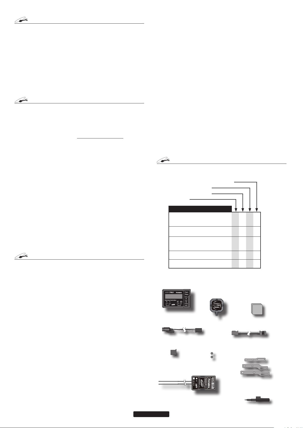
Type of set
• Gyro & Governor set w/R6303SB
• Gyro & Governor set
• Gyro set w/R6303SB
• Gyro set
SET CONTENTS
CGY750 Control Amp
*Mini Screwdriver
*Dust Covers (x3)
Gyro Sensor
*Mounting Pads (x3)
Revolution Sensor
*Sensor Mounting Hardware
*Magnet (x2)
R6303SB Receiver
Extension Cord
CGY750 Control Box
Revolution Sensor
Dust Cover
2
--- --- X X
--- X --- X
X: supplied ---: not supplied
Gyro Sensor
Magnets (2)
R6303SB Receiver
Sensor Mounting Bracket
X X X X
X X X X
X X X X
Mounting Pads
Extension Cord
Adjustment Screwdriver
Page 3
Gyro
RECAUTIONS
P
Meaning of Special Markings
Pay special attention to safety where indicated by the following
marks:
DANGER
and cause death/serious injury if not carried out properly.
WARNING
or cause death or serious injury to the user if not carried out properly
or procedures where the probability of superficial injury or physical
damage is high.
CAUTION
the user is small, but there is a danger of injury, or physical damage, if
not carried out properly.
- Procedures which may lead to dangerous conditions
- Procedures which may lead to a dangerous condition
- Procedures where the possibility of serious injury to
: Prohibited : Mandatory
WARNING
Failure to follow these safety precautions may result in severe
injury to yourself and others.
• Read through the entire manual before operating this product.
BEFORE EACH FLIGHT:
Always check the transmitter and receiver battery voltage to ensure
they have enough remaining capacity to complete the flight.
Always exit programming mode before attempting to fly the model.
Only use the CGY750 with a 2.4GHz system such as the Futaba
FASST™ system, or a PCM system. Use with an FM system is strongly discouraged since interference can cause serious operational problems.
Gyro operating precautions:
The CGY750 requires 5-10 seconds to initialize when the power
is turned on. Do not move the helicopter and do not move the tail
rotor, aileron and elevator sticks during this initialization or the
gyro may not initialize properly. Once the initialization process
has been completed the swash servos and tail servo will move
several times indicating that the CGY750 is now ready for flight.
Verify that the gyros are operating and compensating in the correct
direction before each flight. If the compensation direction is incorrect
on any axis the model will become uncontrollable after takeoff.
Verify that the gyro is operating in the desired mode.
Verify that the gyro mounting pads are in good condition.
Verify that the gyro wires are not contacting the frame of the helicopter.
The servo type parameters within the CGY750 must match the type
of servo you are using. Incorrect setting may damage the CGY750 or
the servos, possibly resulting in a loss of control during flight.
Always ensure that there is some slack in the gyro cables to help
maximize performance. Always use the supplied gyro mounting pads
to attach the gyro to the helicopter mechanics. Do not use a strap that
encompasses the CGY750 sensor. This may affect the overall performance of the gyro.
Always allow the gyro to adjust to the surrounding environmental
temperature before flight. A large temperature change during use will
cause drift and other operational issues.
The gyro sensor and control box have a electroconductive coating.
Do not allow any power leads or other wiring to come into contact with
these items.
If you are switching between Normal Mode and AVCS Mode in
flight, please keep in mind that you must have the gyro re-learn the
center position after making a trim change within the transmitter.
To memorize the new center position simply flip the gain switch on
the transmitter three times between Normal Mode and AVCS Mode
(NormalAVCSNormalAVCS) within one second. The servo will
center indicating that the new center position has been memorized.
When operating the gyro in AVCS Mode, all compensation and
revolution mixing must be disabled and any tail rotor or swash offsets
for flight modes must be disabled.
When the CGY750 is operated in AVCS mode the tail rotor or
swashplate servos will not center when tail rotor, aileron or rudder
stick is released. This is normal operation for AVCS mode. The servos
may also move to the extent while the model is being carried out to the
flight line. Before take off, you must visually center the tail rotor pitch
slider and level the swash plate by using the transmitter control sticks.
You can also center the servos by moving the tail rotor stick full left, then
full right, back to full left and then allow the stick to center within one
second; the same method applies for aileron and elevator servos.
Do not drop the CGY750 sensor onto a hard surface or subject the
CGY750 sensor to a strong shock as this may damage the sensor.
Always use the supplied mounting pads or the Futaba replacement
mounting pads available from your local Futaba dealer.
Governor operating precautions:
When the throttle servo is connected to the CGY750, the battery fail-
safe function within the CGY750 must be setup and enabled.
Throttle fail safe function (transmitter setting): Use the fail safe function for the channel that turns the governor on and off to set the fail safe
position to the point at which the governor is turned off. With this setting,
when the system enters the fail safe state, the governor will be turned
off, and the receiver throttle signal (fail safe position preset) will be out-
put directly.
When using the condition hold function on the transmitter, always
set the throttle servo maximum operating point to less than the point at
which the governor is activated. If this is not done the governor may activate while in condition hold.
While preparing for flight or starting the engine, always ensure the
throttle remains below the governor activation point and do not select
any flight modes that may activate the governor.
If you prefer to activate the governor while the model is still on the
ground, always ensure that you have at least -5 degrees of pitch in the
model before activating the governor. This negative pitch is necessary
to prevent an unexpected lift off as the governor activates and the head
speed increases to the desired RPM.
Periodically check the RPM sensor output to ensure proper governor
operation. Due to the high level of vibration and centrifugal forces the
magnet may come loose or the sensor alignment may change. Every
10th flight verify that the magnet and sensor are properly mounted.
PECIFICATIONS
S
Width (Controller): 1.14in [29mm]
(Gyro sensor): 0.83in [21mm]
(Revolution sensor): 0.30in [7.5mm]
Length (Controller): 1.73in [44mm]
(Gyro sensor): 0.83in [21mm]
(Revolution sensor): 0.63in [16mm]
Height (Controller): 0.47in [12mm]
(Gyro sensor): 0.33in [8.5mm]
(Revolution sensor): 0.39in [10mm]
Weight (Controller): 0.459oz [13g]
(Gyro sensor): 0.282oz [8g]
(Revolution sensor): 0.141oz [4g]
Current Drain: 70mA
Selectable Servo Frame:
Center Pulse Width:
760μs (560Hz)
Governor Resolution: 0.1Hz (6rpm)
(Engine RPM)
RPM Accuracy: 1%
Head Speed Range: 700-4,000rpm
Operating Temperature: 14°F to 113°F
(-10°C to +45°C)
Control System: Digital advanced control
Sensor:
Systems (MEMS) Gyro
Hall effect sensor
Angular Velocity Range: ±1,200 Degrees Per
Second (Gyro)
* The operating voltage shown only applies to the CGY750. Always verify that
your receiver, servos, tail rotor servo, switch and any other electronic components used in your installation are capable of operating at the voltage you plan
to use.
Operating Voltage
Governor
: 3.8V to 8.4V DC*
70Hz, 280Hz and 560Hz
(Rudder Gyro only) Rate
1520µS (70Hz & 280Hz)
Micro Electromechanical
3
Page 4
EPLACEMENT & OPTIONAL ITEMS
R
YRO SENSOR INSTALLATION
G
Futaba PC Interface CIU-2: FUTM0951
Extension 200 mm:
Extension 350 mm:
Extension 55 mm:
Extension 80 mm:
Extension 130 mm:
Mounting Pad:
1x22x22 mm (10)
WARNING
Newer high end servos and other radio equipment
are capable of placing large demands on the power
systems in use today. When using a regulator you
must ensure that the regulator is capable of supplying the current demands of the equipment you have
selected. In addition to this make sure the wiring
and switch you have selected are capable of handling high current draws.
• The servo current draw can be up to 50% higher on a flybar-
less helicopter. Always ensure your receiver battery is fully
charged before each flight.
Even though the CGY750 is a high performance
gyro and governor, it will be necessary to ensure
that the helicopter mechanics are also in optimum
operating condition. Please use the guidelines below and address all issues before installing and flying the CGY750.
• The CGY750 must be used with a rigid tail rotor drive system.
Any modern torque tube or belt drive system should be adequate. Do not attempt to fly the CGY750 using a wire driven
tail rotor system.
• Always ensure the drive gears, torque tube, pulleys, belt,
bearings and shafts are in proper working condition. If any of
these items are damaged or worn they must be replaced.
•
The linkage rod, tail rotor bell crank, pitch slider and tail rotor
grips must operate without friction to obtain the best perfor
mance from the CGY750. Binding in the tail rotor control linkage
will decrease the performance of the CGY750 gyro and this may
also shorten the servo lifespan. Please take the time now to en
sure the tail rotor system on your helicopter is working correctly
and without friction or binding.
• Vibration will affect the CGY750’s overall performance. All
rotating components on the helicopter should be balanced
to minimize vibrations in flight. Ensure that your engine or
electric motor is running smoothly and that all vibrations have
been addressed before installing and test flying the CGY750.
Gyro sensor replacement:
• Each CGY750 gyro control box is calibrated specifically for
the gyro sensor included. Do not attempt to use another
CGY750 sensor with the control box as performance will suffer due to being out of calibration. The calibration process
must be completed by an authorized service center.
If your sensor needs replacement, please send the complete
unit to your region’s support center for repair.
The gyro sensor should be mounted on a rigid platform, at least 6in
[152mm] away from a Nitro Engine. It is not necessary to mount
the gyro near the main shaft of the helicopter but it is very important
that the mounting area chosen is rigid. Please refer to your helicopter
manufacturer’s instructions for recommended mounting locations.
Test t the gyro sensor, ensuring that the sensor is in perfect alignment
with the helicopter on the roll and pitch axis. The cable from the gyro
sensor must exit toward the front or the rear of the helicopter since this
is the pitch axis. Any misalignment will cause a loss of performance,
so it is very important to ensure that everything is aligned properly.
Once you are certain everything is properly aligned and that the sensor
lead can be routed to the gyro, go ahead and mount the gyro sensor
to the helicopter using one of the supplied gyro pads. Route the gyro
sensor lead to the CGY750 control box and plug the lead into the gyro
sensor port. Verify that the connector is rmly locked in place.
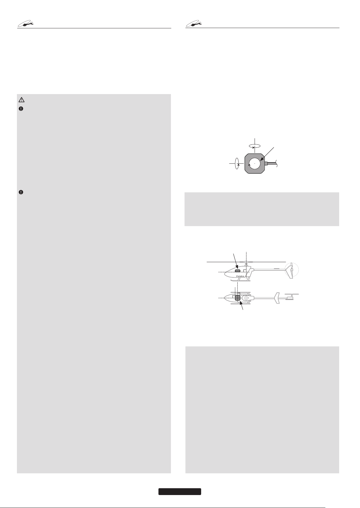
• Elevator (Pitch) axis
• Rudder (Yaw) axis
• Aileron (Roll)
axis
Gyro Sensor
Important: The CGY750 gyro sensor must be mounted so that the
roll and pitch sensing axis are in alignment with the helicopter. Any
misalignments over 1/2 of a degree will cause a loss in performance.
Please take extra care in this step to ensure the optimum flight performance.
• The bottom of the CGY750 Gyro
Sensor must be perpendicular to
the main shaft.
-
-
TROUBLESHOOTING
If any issues are noted during flight (such as drifting, inconsistent hold
or inconsistent control rates) then please review the following troubleshooting recommendations.
1. Always verify that the tail rotor and swash plate mechanisms operate, and that the drive system is in proper working order.
2. Electromagnetic interference could be causing the problem. If you
feel everything is set up correctly and that the helicopter is vibration
free, then consider moving the gyro sensor to a new location away
from servos, ESC and drive motors.
3. Vibrations will decrease the performance of all gyro systems. Even
though the CGY750 gyro sensor is the most vibration resistant gyro
sensor available, eliminating vibrations will always improve performance. Throughout extensive testing it has been found that the
CGY750 gyro sensor performs best when the sensor is mounted
rigidly to the airframe. This is mainly due to the sensing of all 3
axes. It is highly recommended to avoid using soft foam pads as
this may allow the gyro to bounce around on the roll and pitch axis,
causing instabilities and possible loss of control during flight.
• The roll axis must be parallel to
the tail boom and the pitch axis
must be perpendicular to the side
frame.
4
Page 5
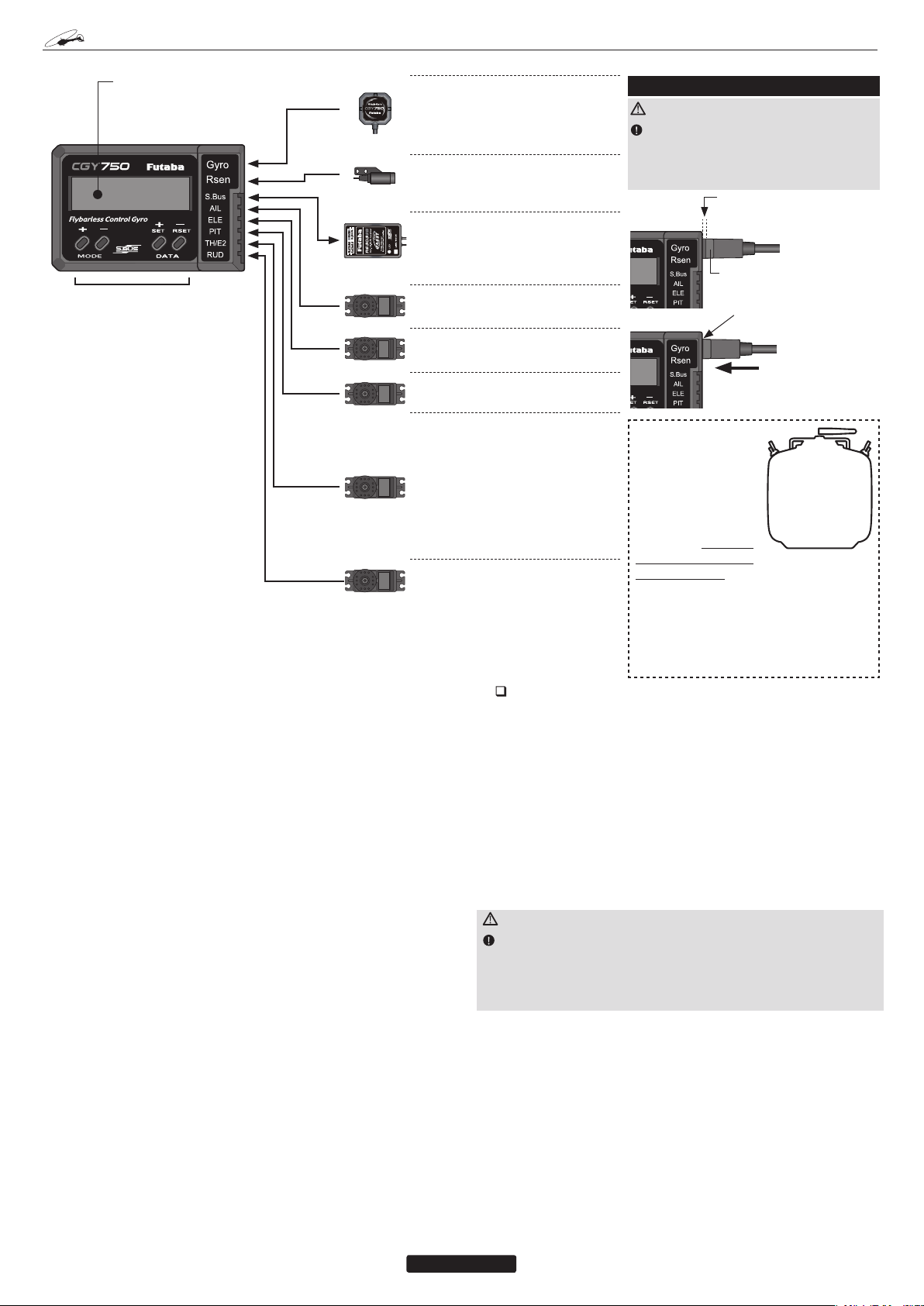
ONNECTING THE
C
CGY750
OLED Display
• Displays menus, parameters and status information.
Edit Keys
• Used when setting data.
• Use the included plastic adjustment screwdriver to press
the buttons.
* This diagram shows the various con-
nections between the CGY750 and
receiver, servo, or sensors.
* If the governor and limiter functions are
disabled when using the [Gyro+THR]
mode then the throttle signal is sent
directly to the TH/E2 connection on the
CGY750. In this case you may connect
the throttle servo to the appropriate
channel on the receiver or to the CGY
TH/E2 connector.
*When the swash mode is set to H4-xx
mode, the TH terminal is changed to
2nd elevator output. In this case, the
governor function is inhibited.
(1)
(2)
(3)
(4)
(5)
(6)
(7)
(8)
(1) Gyro Sensor:
• Connect the gyro sensor.
*Insert the sensor connector until it is
firmly locked.
(2)
Rsen (Revolution sensor)
• Connect the revolution sensor.
(3) S.BUS:
• Connect to the S.BUS output of the
receiver with the supplied extension.
(4) AIL Output:
• Connect the aileron servo.
(5) ELE Output:
• Connect the elevator servo.
(6) PIT Output:
• Connect the pitch servo.
(7) TH Output:
• Connect the throttle servo.
• Connect the ESC w/BEC and set the
operation mode to Gyro+THR mode.
(7) E2 2nd ELE Output:
• Connect the second elevator servo.
(Swash mode: H4-00 or H4-45)
(8) RUD Output:
• Connect the rudder servo.
Connection to the receiver, servos and sensors
The CGY750 requires an S.BUS receiver or the optional PWM Receiver to S.BUS adapter available separately.
Using the supplied extension connect the S.BUS receiver port (or from
the S.BUS PWM adapter) to the CGY750 S.BUS port. Install your
receiver battery, regulator, switch and any other necessary electronics
now. Connect the power lead of your switch / regulator to the battery
connector on the receiver.
Plug the cyclic servos (AIL-[Aileron], ELE-[Elevator], PIT [Pitch],
RUD [Tail Rotor] and if using the H4xx swash plate type TH/E2[Elevator 2]) into the appropriate port on the CGY750.
Determine the best location to place the receiver and CGY750 control
box. Mount the receiver and the CGY750 control box to the helicopter mechanics using vibration adsorbing self adhesive foam pads. The
CGY750 gyro sensor will be installed in a later step.
Using wire mounts, wiring xtures molded into the helicopter, or hook
and loop material, route the servo leads and extensions. Make sure the
wires are not rubbing against metal or carbon ber which may damage
the wires.
S.BUS channel setting
Since the S.BUS protocol uses a single wire to transmit all channel
information to the CGY750 it is necessary to assign each channel
number (1 through 16) a function (such as aileron, pitch, collective,
gain, ail gain, ele gain, rpm, gv on/off) within the CGY750 control
box. The default CGY750 S.BUS channel assignments should work
properly with most Futaba transmitters. If you experience any problems please refer to the S.BUS section of the manual to set/verify each
channel number for each function.
Installing the Sensor Connector
WARNING
You will feel resistance at two points
when inserting the connector. Make sure
:
that you plug in the connector completely,
or connection problems may result.
1) First resistance (incomplete
connection)
Locking tab
2) Second resistance (fully
connected)
●Continuepushingtheconnectoruntil you hearthe locking tab
“click.”
Your transmitter
should be reset
to the default
settings and the
Swash Type
swash plate type
selected with the
transmitter should
H-1
be set to Normal
(H-1) or single
servo mode. All
CCPM mixing is set up and handled
with the CGY750, and the transmitter
functions should not be used. Before
starting helicopter set-up, be sure
that all dual rates, pitch curve, and
endpoint values are set to 100/100.
If your transmitter does not offer enough channels to operate all of the
CGY750’s functions, it is possible to operate the CGY750 without the
GV On/Off, Ail Gain, and Ele Gain channels connected. When any these
functions are not used, it is necessary to set the channel number to [INH]
within the CGY750’s S.BUS menu to disable the function and to use the
setting value inside the CGY750 menu instead.
When the GV On/Off channel is not used, the governor on/off control is
handled by the [Stick Switch] function.
When the remote Ail or Ele Gain channels are not used, the operating
mode (NOR/AVCS) and gain value can be set in the appropriate AIL /
ELE Basic menu option by using the Data +/- keys when the function is
displayed.
Using the CGY750 with a electric helicopter
DANGER
It is necessary to remove the pinion gear from the electric motor
or disconnect the motor from the ESC before powering the model
up for setup or bench testing. Electric motors are extremely powerful and capable of delivering the power instantly, causing injury
to yourself, others, or the surroundings.
If the CGY750 is being installed into an electric helicopter and the
ESC’s own internal governor is to be used, you may want to consider
connecting the ESC to the [TH/E2] (throttle / elevator 2) output of the
CGY750. Before doing this you must remove the pinion gear from
the electric motor or disconnect the motor from the ESC before powering the model up the rst time. Once the model has been powered up,
navigate to the gyro mode function and set it to [GYRO+THR]. This
sets the CGY750 to act as a gyro and throttle output. The CGY750
will simply pass the throttle signal from the receiver through to the
TH/E2 port on the CGY750.
Once your ESC is connected to the CGY750, you must complete all
necessary transmitter setup (ATV / EPA / REV / ETC) per your ESC
instructions. Please refer to the end of this manual for further suggestions for the use of the CGY750’s governor with electric powered
models.
5
Page 6
TX Set-up
Condition selection
Condition selection incorporates two adjustable values for a given
parameter (displayed c1/c2). This is dictated by the digital channel
number “1” within the Function Menu of your transmitter (DG1). Assigning DG1 to a switch or ight mode allows the use of two separate
variables on the condition selectable parameters.
Rotor Head Gyro Gain “RotHd.Gn”
In the SBUS menu assigning “RotHd.GN” to a channel will allow the
Rotor head gain to be adjusted via the TX. If you are using a 6CH or
less TX, setting “RotHd.Gn” to “INH” will then default the gain to
“BaseGain” in the Flight Tuning menu. Suggested setting and default
is CH9.
Tail Rotor Gain “RGn”
In the SBUS menu assigning “RGn” to a free TX channel will allow
for the tail rotor gain to be adjusted via the TX. Suggested setting and
default is CH5.
Note - Before starting helicopter set-up, be sure that all dual rates,
pitch curve, and endpoint values are set to 100/100.
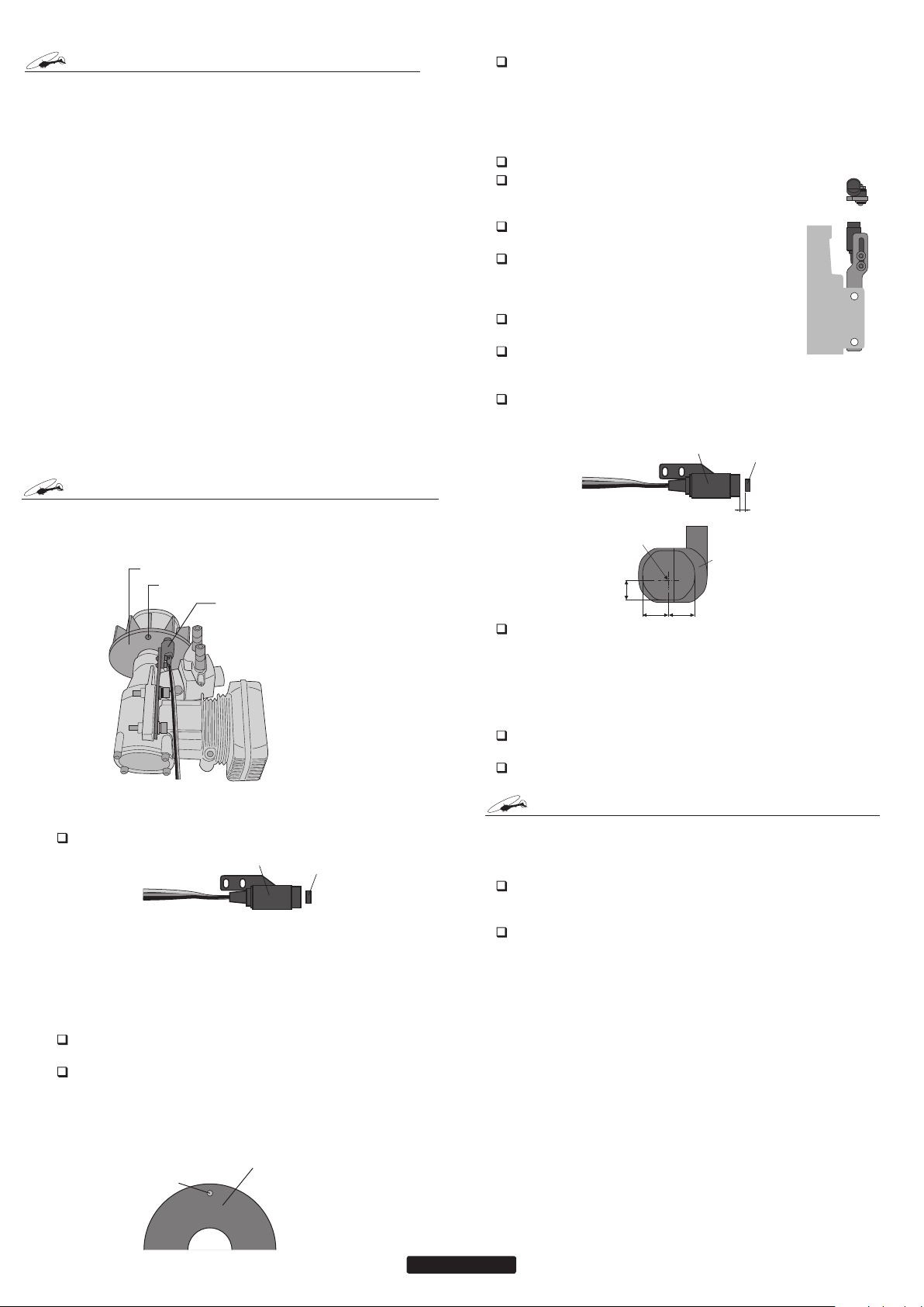
OVERNOR INSTALLATION
G
Modify the cooling fan and install the accessory magnet and attach the
magnetic sensor to the engine at the position shown below. Balance
the cooling fan as needed following magnet installation.
Cooling fan
Magnet (Embedded in cooling fan.)
Sensor (Attached to engine flange
through a stay.)
When installing the sensor magnet to the mufer side, also refer
to the needle side mounting.
If the cooling fan is unbalanced and vibrates, etc., balance it by mounting
the spare magnet to the opposite side of the cooling fan in the opposite
polarity (so that it does not output a signal).
Sensor mounting
The sensor mounting method depends on the helicopter and engine.
Mount the sensor to the sensor stay. (Temporary assembly)
Drill a hole in the fan cover at the part corresponding to
the sensor so that the distance between the sensor and
magnet can be made 1 to 2mm.
Tighten the sensor stay together with the engine mounting
ange. (Temporary assembly)
Select the mounting method so that the sensor does not
touch the frame, or other parts of the helicopter. Temporarily mount the sensor and select the magnet mounting position.
Install the sensor to the sensor stay using the accessory
screws and washers.
Tighten the sensor stay together with the engine using the
engine mount screw.
Sensor adjustment
Adjust the sensor position to obtain a sensor output of at least 60% in the
“Revolution sensor testing” menu within the “Governor Basic Setting”
section earlier in this manual.
Sensor
Center of sensor
is offset.
2.2
mm
3.7mm 3.7mm
The center of the sensor is different from the center of the sensor case so
be careful when mounting the sensor.
If the display is less than 60% when the magnet is directly below the
sensor, bring the sensor closer to the magnet so that the 60% or more is
displayed. The magnet and sensor gap criteria is approximately 1 to 2mm.
If a sensor output is not obtained even when the sensor is brought close to
the magnet, the magnet and sensor center positions may have changed.
Complete assembly of the sensor by securely tightening the screws that
were temporarily tightened.
Recheck the sensor output.
Sensor
case
Magnet
1-2mm
Magnet operating side check
Bring the magnet near the end of the sensor and check the operating side.
Sensor
This is the side at which the displayed value increases in the “Revolution
sensor testing” menu within the “Governor Basic Setting” section earlier
in this manual. Install the magnet with this side facing the sensor. Mark
this side of the magnet with a felt tip pen.
Magnet
Cooling fan modication
Drill a hole in the fan at the magnet mounting position. Make the hole
about 4.1mm in diameter and 1.5 to 1.7mm deep.
Embed the magnet in this hole in the direction in which an output is ob-
tained. Use epoxy adhesive that cures in 30 minutes or longer. Do not use
epoxies that contain metal such as JB Weld.
Cement the magnet to the cooling
fan so that the magnet is level
with this side of the cooling fan.
Magnet
OVERNOR FUSELAGE SETTING PRECAUTIONS
G
Throttle servo linkage precautions
To effectively use the governor, observe the following precautions
when connecting the servo linkage.
Make the servo operating range as wide as possible. Make the throw of
the transmitter EPA (ATV) function and AFR function as close as possible
to 100%.
Fly with the governor turned OFF and adjust the needle so that the engine
smoothly reacts to movement of the transmitter stick.
If there is a point at which the reaction of the engine is considerably dif-
ferent due to a too rich or too lean mixture, the governor may not operate
to its maximum potential.
Fuselage vibration countermeasures
If the helicopter frame is weak, or the engine mount is deformed or not
installed properly, the vibrations applied by the engine will increase.
Engine vibrations will lead to unstable speed and prevent the governor
from providing maximum performance. Therefore, make sure that the
engine is vibration free and that the carburetor provides linear throttle
control because the governor cannot correct engine problems.
Use of a tuned silencer
The use of a tuned pipe type silencer may cause the engine throttle
response to be substantially different from that of a normal mufer.
Adjust the needle (and pipe length) so that engine speed changes are
proportional to the throttle opening. The governor will not perform
satisfactorily with a mufer or a pipe that does not allow the carburetion to be linear.
6
Page 7
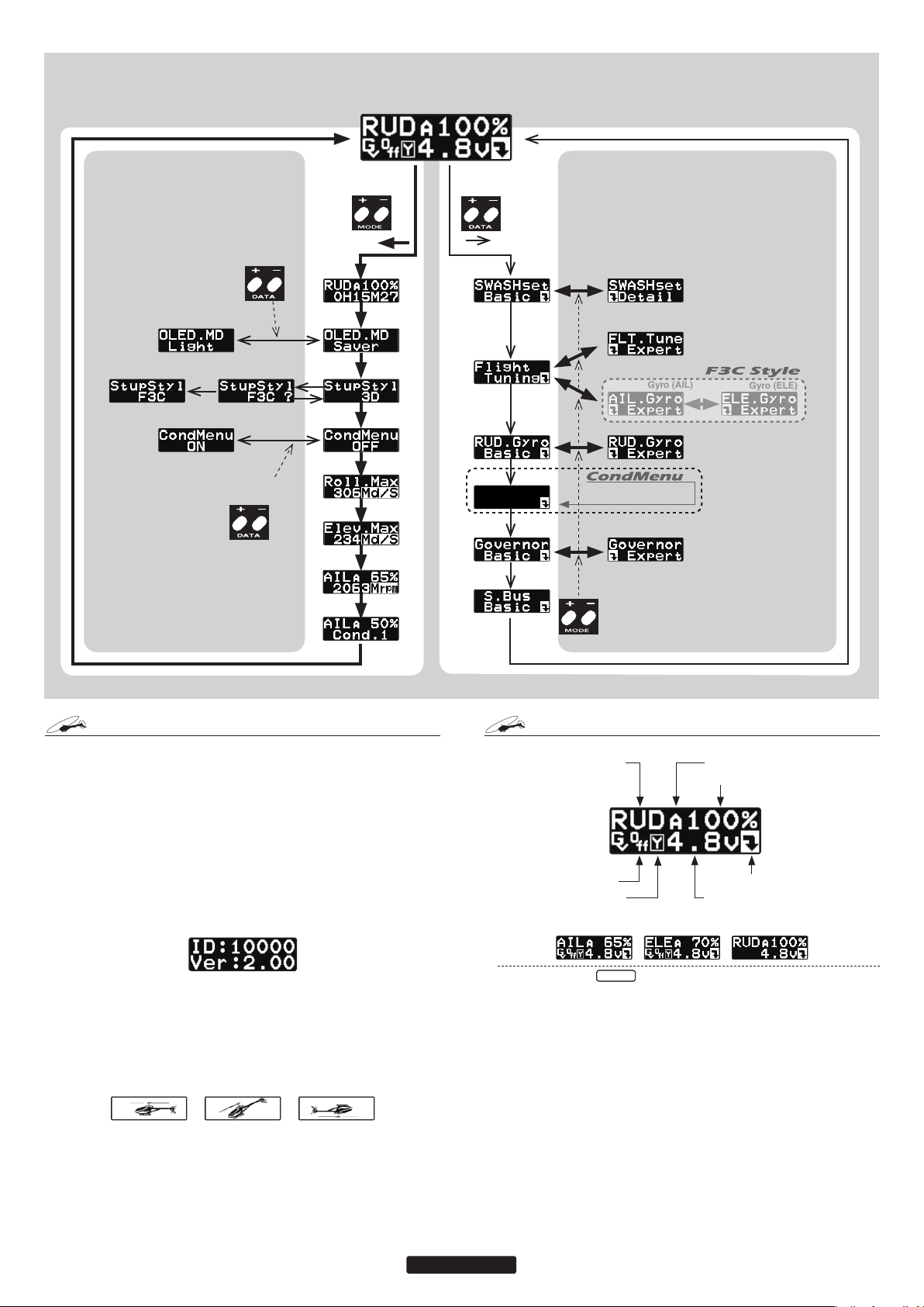
Gyro
FIRST MAP
The figure shows the first layer of the editing
sequence.
Home screen
Rudder gain display
Push
DATA
+ key
Push
Push
+/– key
DATA
+/– key
DATA
Push
- key
+ key
Push
Thick line
shows MODE.
DATA
MODE
+/– key
Engine
runtime
OLED
Setting
Setup style
Condition
Menu
Maximum
Roll Rate
Maximum
elevator rate
Maximum
RPM
Condition#
indication
Push
+/– key
DATA
Thin line
shows DATE.
CondData
Cond. 1
Swash
Flight Tuning Expert
Gyro (AIL)
When CondMenu is ON, this
changes into CondMenu.
Governor
Push
for
1 second
MODE
+/– key
Gyro (ELE)
Gyro (RUD)
PENING SCREEN
O
Verify that all of the connections are correct between the CGY750, receiver, and power supply. If your helicopter is using an electric motor
for propulsion, remove the pinion gear now for safety.
If this is the rst time the helicopter has been powered up, remove the
servo arms and linkages to prevent damaging the servos if any binding
is present. Power up the transmitter and allow it to initialize. Turn
the receiver on or connect the ight battery and allow the helicopter to
remain motionless while the CGY750 initializes.
The display will rst show the ID number of your CGY750 and the
Firmware Version.
After the CGY750 has powered up the screen will change to show an
animation of a helicopter performing a stationary ip. This indicates
that the initialization process is taking place. The helicopter must remain perfectly still so the controller can determine the gyro’s center
position for each axis.
Once the initialization process has been completed the Home Screen
will be displayed and the cyclic + tail rotor servos will move several
times in quick succession.
If the CGY750 is set to the [Gyro+THR] mode or if the H4-xx swash
plate type has been selected then the governor will be disabled and the
screen will look like (d) below instead. The display will cycle through
and show the current AIL, ELE and RUD gains.
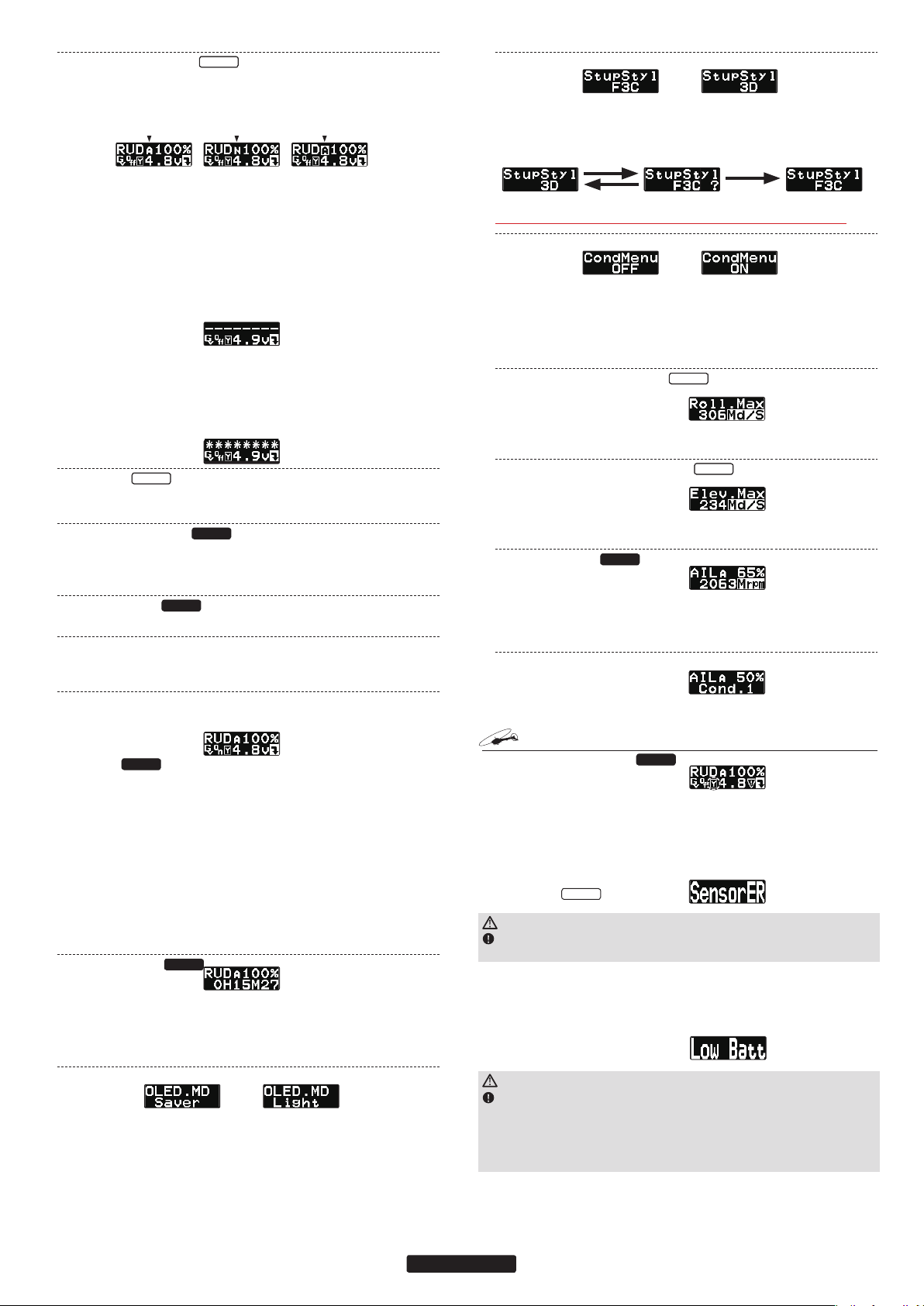
Home S
CREEN
Initial Home screen
1. Axis indication 2. Gyro operation mode
4. on/off switch
5. Yaw rate comp
(b) Aileron gain
display
(c) Elevator gain
1. Axis indicator
The axis indicator will cycle every two seconds and show the axis (AIL,
ELE or RUD) and their respective current gain values.
display
3. Gyro gain
7. Setting Menus
6. Battery voltage
(d) Gyro only
mode
7
Page 8
2. Gyro operation mode
Gyro
Gyro
Gyro
Gyro
The display indicates either [A] for AVCS or [N] for Normal operating modes. If the [A] is shown in inverted colors then the rudder
neutral is offset and re-learning the center position should be completed immediately.
RUD AVCS Mode
at 100% gain
When using the AVCS operating mode, the servos will not re-center when
the control stick is released. If you need to center the servo, you can move
the appropriate control stick to its full extent (left & right or up & down)
twice and allow the control stick to return to center within a one second period of time, and the servo(s) for that axis will return to center position.
For example if you move the tail rotor stick full left, full right, full left, full
right and allow it to come back to center within one second, then the display
will change to show [--------], and the tail rotor servo will center.
When using the AVCS operating mode and if trim changes have been made
on any axis, then the neutral position must be read and memorized by the
CGY750. To do this simply change the operating mode twice within one
second (for example Normal → AVCS → Normal → AVCS) and the display
will change to [********] to indicate that the current stick position has been
memorized as the new neutral position.
3. Gyro gain
This indicates the current gyro gain for the axis noted in the Axis Indicator
position.
4. Operating condition
This indicates whether the governor is [ON] or [OFF].
RUD NOR Mode
at 100% gain
Governor
Neutral offset at
AVCS mode
Return servo to center position
Read and memorize the current
neutral position.
3. Setup style
3D Mode is a known conguration of parameters for 3D and F3C ying.
F3C Mode is for Advanced F3C tuning only.
Push
DATA
+/– key
*The changed menu is indicated on a map.
– key
Push
DATA
+key
*When the style is changed, setting of AIL/ELE/RUD is initialized.
4. Condition menu [default: OFF]
2 conditions can be established by the switch (DG1) of the transmitter.
When the condition menu is turned on, [CondMenu] appears newly.
It becomes possible to change the function indicated by a map of [CondMenu]
to 2 conditions.
The function included in [CondMenu] disappears from the usual menu.
5. Roll rate maximum display
This screen displays the maximum roll rate recorded during flight. This
value is reset back to 0 when the CGY750 is powered up.
6. Elevator rate maximum display
This screen displays the maximum elevator rate recorded during ight. This
value is reset back to 0 when the CGY750 is powered up.
7. Maximum RPM
Governor
5. Yaw rate comp.
Governor
This indicates that the Governor yaw feed forward function is enabled.
6. Battery voltage
This indicates the battery voltage. The display will change to show [LOW BAT]
once the voltage has fallen below the Battery fail safe voltage setting (BFS).
7. Setting Menus
Pushing this button will exit the normal operating mode and enter the settings menu mode.
RPM display
Governor
The battery voltage display automatically changes to the engine RPM
display once the engine is running and returns to battery voltage display once the engine has stopped running. The RPM display can be
either the head speed or the engine speed depending on the setting
in the revolution display mode setting found in the governor Expert
menu.
Home screen options
When the home screen is shown the mode [+] and [-] keys can be used
to cycle the bottom line through the following items; Battery voltage,
Max RPM, Engine runtime, OLED display options, Operating Mode,
Roll rate maximum display, and Elevator rate maximum display.
1. Engine runtime
From the home screen press the mode [+] key twice to show the engine
runtime display. The time shown is how long the engine has been running.
This is a cumulative timer and the value is maintained in memory. To reset
the timer simply press the data [+] or [-] key for more than one second and
the timer will reset back to 0.
2. OLED display options [default: Saver]
When the [Saver] option is selected, the display will dim after 60 seconds
of inactivity. Once a button is pressed on the CGY750 controller box, the
OLED will switch back to full brightness. The [Saver] option helps to conserve power and extend the life of the display. When the [Light] option is
selected the display will remain at full brightness at all times.
Governor
From the home screen press the mode [+] button once to show maximum recorded RPM [Mrpm]. The [Mrpm] value is maintained until you clear it by
pressing the data [+] or [-] key for at least one second. This function allows
you to check for over speeding during ight.
8. Condition #
Current condition# is indicated.
ARNING DISPLAY
W
Governor warning display
Governor
The warning symbol is displayed when the governor is activated during power up. Immediately switch to a condition that has the governor
disabled, and the symbol will disappear. When this warning symbol
is shown, the governor will be disabled until the ight condition has
been turned off. The engine must be started with the governor turned
off.
Sensor Error
WARNING
The helicopter must remain motionless during the initialization process
or a [SensorER] sensor calibration error may occur.
Gyro
If a sensor error occurs during initialization, the sensor itself may be
defective.
Please contact your region’s technical support center (the contact information can be found in the beginning of this manual).
Low battery
WARNING
The [Low Batt] warning is displayed if the receiver battery voltage falls
below the [BAT/FS] voltage set within the CGY750 Governor Expert menu.
If this condition lasts for more than one second, then the Battery Fail Safe
function activates, and the throttle servo is brought back to idle position.
This is done to warn you that the battery voltage is dangerously low and that
you must land immediately.
8
Page 9

The throttle operation can be temporarily reactivated by bringing the
transmitter control stick all the way back to idle; normal throttle function will return. After 30 seconds the Battery Fail Safe function will
activate again requiring you to repeat this process if necessary. The
model should be landed as soon as possible.
Memory writing indicator
WARNING
Do not power off the CGY750 when the Memory writing symbol is dis-
played.
When a setting is changed within the CGY750 the new value must
be written to memory. The “Memory writing indicator” is displayed
during this process. This process may take up to two seconds, and the
power must not be switched off during this time.
If the power is switched off during the writing process, then all of the
settings may be lost.
ETTING MENUS
S
WARNING
Always exit the Setting Menu and return to the home screen before fly-
ing your model. The gyro operation is disabled within several of the settings menus to ease set up.
Always check the operation of the CGY750, verify that the controls are
operating the correct direction and ensure the gyros are correcting in the
proper direction for all axes prior to attempting to fly the model.
The data [+] and [-] keys are used to navigate through the Setting
Menus: [RUD.Gyro], [AIL.Gyro], [ELE.Gyro], [SWASHset], [Governor]* and [S.BUS] Basic menus. Once the desired menu is shown
press and release the mode [+] or [-] key to show the next or setting
items respectively.
The expert menus are entered or exited by pressing and holding the
mode [+] or [-] key for one second. To exit the current menu simply
go back to the Basic Settings Menu for the function (for example,
[AIL.Gyro - Basic]) and press and release the mode [+] or [-] key
until the home screen is shown.
Please see the Setting Menus diagram for a complete listing of the
Home Screen, Basic and Expert menus.
*The [Governor] setting menu is not displayed if the Operating Mode has been
set to [Gyro+Thr] or if the swash plate type has been set to the H4 xx type.
9
Page 10
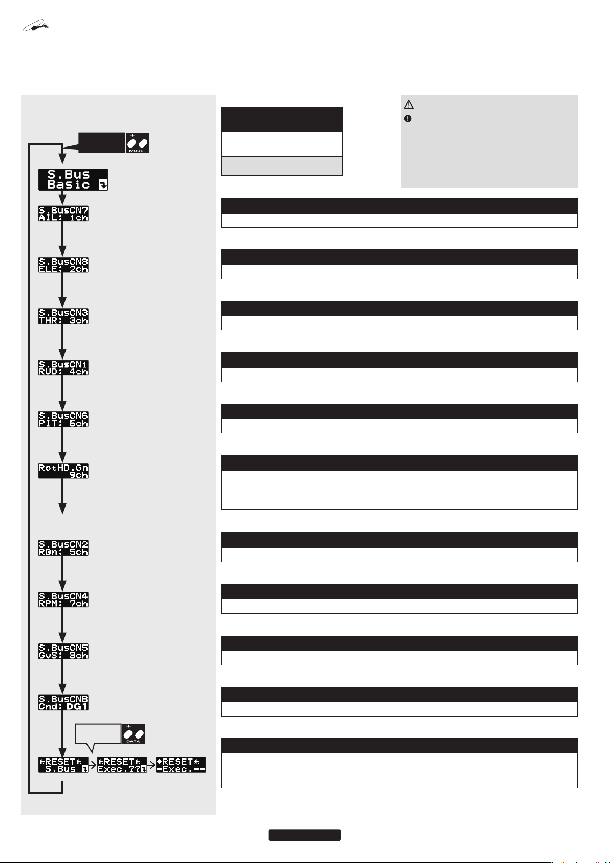
BUS BASIC SETTING
S.
Since S.BUS sends all 18 channels (may be limited by your transmitter) over a single wire, it is necessary to assign a CGY750 function (such as
AIL, ELE or PIT) to each channel. The channel assignments are performed within the [S.BUS].Basic menu.
If a function is not going to be used, then it must be set to [INH]. For example, if the AGN and EGN remote gain functions are not going to be used,
then set them to [INH] and the CGY750 will then allow you to make gain adjustments within the respective menu.
S.BUS BASIC MAP
Push
MODE
+/– key
(1) S.BUS connection setting:
start display
Use the mode [+] or [-] keys to
navigate through the menu.
Setting ranges common: 1 ~ 16ch, DG1,
DG2, INH
Always verify that the S.BUS function assignments match your transmitter’s function
(in the FUNCTION menu) assignments. If any
changes are made within the transmitter function assignments, then it will also be necessary
to make the changes within the S.BUS function
assignments.
(2) S.BUS setting: Aileron channel [default: 1ch]
WARNING
Using the data [+] or [-] keys to set the correct channel number.
(3) S.BUS setting: Elevator channel [default: 2ch]
Using the data [+] or [-] keys to set the correct channel number.
(4) S.BUS setting: Throttle channel [default: 3ch]
Using the data [+] or [-] keys to set the correct channel number.
(5) S.BUS setting: Rudder channel [default: 4ch]
Using the data [+] or [-] keys to set the correct channel number.
(6) S.BUS setting: Pitch channel [default: 6ch]
Using the data [+] or [-] keys to set the correct channel number.
(7) Rotor head gain: AIL and ELE gain channel [default: 9ch]
“RotHd.GN” to a channel will allow the Rotor head gain to be adjusted via the TX. If you are using a
6CH or less TX, setting “RotHd.Gn” to “INH” will then default the gain to “BaseGain” in the Flight Tuning menu. Suggested setting and default is CH9.
(8) S.BUS setting: RUD gain channel [default: 5ch]
Using the data [+] or [-] keys to set the correct channel number.
(9) S.BUS setting: RPM channel [default: 7ch]
Using the data [+] or [-] keys to set the correct channel number.
(10) S.BUS setting: GOV. on/off channel [default: 8ch]
Using the data [+] or [-] keys to set the correct channel number.
(11) S.BUS setting: Conditionon change channel [default: DG1]
Using the data [+] or [-] keys to set the correct channel number.
Push
DATA
+/– key
(12) S.BUS data reset
This resets the S.BUS channel assignments back to the defaults. Press the data [+] key and [Exec
??] will be displayed as a confirmation. Press data [+] to confirm the reset back to the default settings.
10
Page 11

WASH SERVO INSTALLATION AND SETUP
S
The CGY750 supports 6 different swash plate types as shown below.
FRONT
H3-120
PIT AIL
ELE
H3-90
PIT AIL
ELE
H4-45
ELE
PIT
AIL
ELE2
H3-140
PIT AIL
ELE
H4-00
ELE
PIT AIL
ELE2
Normal
PIT
AIL
ELE
Swash Servo installation
Determine which of the swash plate types shown match your helicopter
and install the swash plate servos per the diagram and per your helicopter’s instruction manual.
Your transmitter should be reset to the default settings and the swash plate
type selected with the transmitter should be set to Normal (H-1) or single
servo mode. All CCPM mixing is set up and handled with the CGY750,
and the transmitter functions should not be used. The expo function and
dual rates can be used with the transmitter but everything related to the
CCPM mixing should be set up and handled by the CGY750. Set your
transmitter AFR, ATV and D/R (Swash functions) to 100% initially for
setup, and all subtrims should be set to 0.
Power up your transmitter and helicopter. Allow the CGY750 to initial-
ize. Use the CGY750 [SWASHset Basic].
Navigate to the Servo Type parameter on the CGY750 and select the servo
type that matches your servo manufacturer’s recommendations. If there
is any doubt, select the analog servo type to prevent damaging the servos
and check with your servo’s manufacturer to determine the proper type.
Navigate to the [SWASHset Basic] AIL.Ntr setting at this time. The
AIL,ELE, or PIT.Ntr setting screens will each disable the gyros and cause
the cyclic servos to remain in the center position. If you are using an
electric motor, then it will be necessary to remove the pinion gear now or
disconnect the motor from the ESC. Once you are certain that the drive
motor cannot apply power to the main rotor blades, temporarily install
servo arms onto the servos. Slowly move the collective stick towards
positive collective and verify that each servo is moving the proper direction to increase collective pitch. If the servos do not move in unison to
maintain a level swashplate with a collective pitch input, choose another
servo combination option from the ServoDir Comb# menu.
Once the servos are operating in the correct direction for the collective
control (positive and negative), the next step is to slowly move the collective stick to the center position (verify within your transmitter’s servo
Display or Monitor function if possible). This will be considered the 0
collective position for setup. Temporarily install the servo arms onto the
cyclic servos and ensure that the servos are perfectly level. Small adjustments can be made using the [SWASHset Basic] → AIL/ELE/PIT.Ntr
adjustment for each servo if necessary. Mount the linkage ball onto the
servo arm per your helicopter’s instruction manual and install the servo
retention screw onto each servo. Remember to use loctite on these screws
if your servos have metal output gears.
Move the forward / aft cyclic stick forward and verify that the swash plate
tilts forward. If the swash plate tilts the wrong direction, then it will be
necessary to reverse the sign of the [SWASHset Basic] ELE.Dir parameter
(for example +50 would become -50). Move the left / right cyclic stick to
the right and verify that the swash plate tilts to the right. If the swash plate
tilts left, then reverse the sign of the [SWASHset Basic] AIL.Dir parameter.If the collective pitch movement is opposite to the transmitter input
(positive stick input yields negative collective on the model), reverse the
direction using SWS.Dir PIT.
As a nal check, verify that the swash plate moves in the proper direction
per your stick movements for the roll, pitch and collective functions.
Navigate to the [SWASHset Basic] → SWS.Rate parameter. This will
disable the gyros and cause the servos to remain centered during set up.
Using a pitch gauge, ensure that the swash plate is perfectly level and that
the main rotor blades are at 0 degrees pitch when the collective stick is
centered. Make any mechanical adjustments as needed to achieve 0 degrees of pitch on both main rotor blades.
Rotate the main rotor blade with the pitch gauge so that it is aligned with
the tail boom. Apply full right cyclic on the transmitter and measure how
much pitch is on the blade. At least 9 degrees of cyclic pitch should be
set. Adjust the value of the [SWASHset] → Basic → SWS.Rate parameter
until at least 9 degrees of cyclic pitch is achieved.
OR…….Rotate the main rotor blade so that it is perpendicular to the tail
boom and apply full aft cyclic. Adjust the [SWASHset] → Basic → SWS.
Rate parameter until at least 9 degrees of cyclic is achieved.
Using the pitch gauge, adjust the collective range per your preference or
per your helicopter’s instruction manual.
All of the AFR, ATV and D/Rs for the cyclic and collective functions
within the radio should be set to 100%. At this point the basic setup is
complete, but it is necessary to set up the gyros and compensation directions before attempting to y the model.
Navigate to the AGy.Dir and EGy.Dir parameters in the [Swashset Basic]
menu.
These parameters control which direction the CGY750 (roll / pitch axis)
will compensate when the helicopter rolls (pitches). Pick the helicopter
up and roll the helicopter to the right. The CGY750 should compensate
by adding left cyclic to the swash plate. (Pick the helicopter up and rotate
the nose of the helicopter downward. The CGY750 should compensate by
adding aft cyclic to the swash plate.) If the CGY750 compensates in the
wrong direction, reverse the Compensation Direction setting by pressing
the DATA [+] or [-] key once.
Check the cyclic and collective movements for interactions and if any are
noted please refer to the Swash Plate Adjustment (Linkage Compensation)
procedure listed within the back of this manual. When using modern digital servos and with a proper setup, adjustments required will be minimal
if any at all. Sometimes mechanical design aws or mistakes within the
setup will cause interactions, and it is best to remove these before ight.
ILERON / ELEVATOR GYRO SETUP
A
Finishing the setup:
Using the Remote Gain Functions (roll, pitch and yaw)
1. Some Futaba transmitters contain auxiliary gain functions for aileron,
elevator and yaw. Please refer to your transmitter’s instruction manual.
Assign the GYR, GYR(AIL) and GYR(ELE) channels within the transmitter. Within the CGY750 [S.BUS] Basic menu→Rotor Head Gyro Gain
“RotHd.Gn” – In the SBUS menu assigning “RotHd.GN” to a channel
will allow the Rotor head gain to be adjusted via the TX. If you are using
a 6CH or less TX, setting “RotHd.Gn” to “INH” will then default the gain
to “BaseGain” in the Flight Tuning menu. Suggested setting and default
is CH9. Tail Rotor Gain “RGn” – In the SBUS menu assigning “RGn” to
a free TX channel will allow for the tail rotor gain to be adjusted via the
TX. Suggested setting and default is CH5.
2. The gyro function within your transmitter should list all three gain channels. Adjustments can be made from within this function. The gyro function can usually be assigned to various switches or conditions to offer
greater adjustability. Please refer to your transmitter’s instruction manual
for further details.
3. Initially the AIL and ELE gains should be set to 60% and the operating
mode should be set to [NOR]. Once the trim process has been completed,
the ight mode should be changed over to [AVCS]. When the AIL and
ELE gyros are in CMT mode, [NOR] versus [AVCS] may be selected
in the gyro menu in the transmitter (Futaba transmitters). Alternatively,
[NOR] versus [AVCS] may be manually selected in the CGY750.
Setting the CGY750 gains by using endpoints or manual adjustments
WARNING
Verify that the gyro compensates in the correct direction for all
three axes before flight. If the compensation direction is incorrect,
the model will roll, flip, or pirouette uncontrollably even before it
leaves the ground.
1. If your transmitter does not support the remote gain adjustment it is still
possible to use spare channel on the transmitter to make the adjustments.
Assign unused channel (verify that these channels are not assigned or
operated by a switch or dial) within the transmitter. Set the [S.BUS.
Basic] → “RotHd.Gn” channels to the appropriate channel. Use the end
point adjustment within your transmitter for these channels to make the
gain adjustments and the reverse function within the transmitter to set the
mode [AVCS/NOR]. Conditions with the transmitter may also be used
to achieve different gains based upon ight modes. Please refer to your
transmitter’s instruction manual for further details.
Manual gain adjustment
1. If your setup does not leave any channels free or if your transmitter does
not support auxiliary gain adjustment, then it is possible to adjust the gain
manually within the CGY750. Set both the [S.BUS].Basic → RotHd.
Gn to [INH]. The gain adjustments are now made by entering the [Flight
Tuning] → Base Gain and pressing the data [+] or [-] keys.
11
Page 12

WASH BASIC SETTING
S
The [SWASHset] →Basic menu contains all of the functions necessary to set up the swash plate servos and to set up all swash plate mixing functions.
SWASH BASIC MAP. 1/2
Push
MODE
+/– key
Push
DATA
+/– key
Push
DATA
+/– key
Push
DATA
+/– key
(Confirmation screen)
(1) Start display
The editing menus are
scrolled by pushing the
MODE+ or – key
(2) Operation mode [default: Gyro+Gov]
This selects the operating mode of the CGY750.
[Gyro+Gov] Both the gyros and the governor are operational.
[Gyro+THR] The gyro is operational, and the governor is
disabled. The throttle channel from the receiver is passed
through to the [TH/E2] port on the CGY750.
[Gyro+H4] Must be selected when a [H4 xx] swash plate
type is selected. This disables the governor and throttle
servo output and the [TH/E2] port on the CGY750 is now
the second “Elevator” [E2] servo output.
(3) Servo type [default: DG:285Hz]
This selects the swash servo types. There are four kinds of
the servo driving frequency selection, AN:70Hz, DG:95Hz,
DG:140Hz, DG285Hz. Previous version supported Analog= AN: 70Hz and DG:1520= DG:285Hz only. All Futaba
digital servos can be worked with fastest DG:285Hz mode
but some of other brands servos do not support DG:285Hz
mode. In this case, select the proper servo driving frequency to meet the servos.
(4) Swash type [default: H3-120]
Select the swash plate type. Pushing the DATA+ or – key,
display shows the confirmation screen as xxx? Pushing
the SET key, the type is changed. Pushing the RSET key
or no operation the key for more than 1 second, the display
returns to previous setting. When the type is changed, all
swash parameter are reset.
WARNING
If the operating mode has been
changed, then the CGY750 must
be reset by powering down and
then powering back up.
WARNING
Read your servo instruction
sheet to determine the proper
servo settings. The servo type
parameter within the CGY750
must match the type of servo
you are using. Incorrect setting
may damage the CGY750 or the
servo. Incorrect setting may also
result in a loss of control during
flight.
WARNING
All of the swashplate parameters are reset when the swash
plate type is changed. Please
proceed through the entire setup
process before attempting to fly
the model.
Push
DATA
+/– key
*It does not display, when Opr.mode is
Gyro+THR, and when SWASH-type is
H4-00/H4-45.
(5) Swash servo direction setting [default: 1]
This parameter facilitates achieving proper swash servo movement electronic CCPM models
(eCCPM) In the H3-xx swash mode, three of the swash servos directions are changed by pushing the DATA[+] or DATA[-] key. Choose the combination number which produces level swashplate
travel with a collective pitch input from the transmitter. There are 8 combination choices for the
H3-xx swash mode. On H4-xx swash mode, there are 16 combination choices. After selecting the
combination number, aileron, elevator, pitch, and 2nd elevator servo parameters are automatically set.
NOTE: Occassionally the aileron or elevator function directions are reversed even though collective pitch direction is correct. In this case, change the direction of the affected function using the
SWS.Dir parameter. The sign of its value will change from (+) to (-) or vice versa.
(6) Swash direction setting [default: +]
This selects the aileron, elevator and corrective pitch direction. Reverse the direction when the
stick movement and swash movement are opposite.
(7) Servo neutral adjustment [default: 0µS ranges: -116~0~+116uS]
This menu is effectively a subtrim or individual neutral adjustment for each of the swash plate
servos. All servo arms should first be positioned as perpendicularly as possible to the control
linkage with the collective stick positioned at 0 degrees collective (usually centered at half stick).
Only then and if needed should neutral adjustments be made with goal being to keep them as
small as possible. The ELE2 neutral adjustment only works if the H4-xx swash plate type has
been selected.
To use this function select the servo you would like to adjust and press the DATA [+] or [-] key to
position the servo as desired.
12
Page 13

WASH BASIC SETTING
S
SWASH BASIC MAP. 2/2
Push
MODE
+/– key
When CondMenu is ON, this
changes into CondMenu.
When CondMenu is ON, this
changes into CondMenu.
When CondMenu is ON, this
changes into CondMenu.
Push
DATA
+/– key
Push
DATA
+/– key
(8) Swash Rate (rate adjustment) [default: 50% ranges: 0~100%]
The Swash Rate settings are used to adjust the amount of throw allowed for roll (aileron) and pitch
(elevator). The one setting applies to both roll and pitch axes; they are not individually adjusted.
Use the Data [+] or [-] key to make an adjustment.
(DUAL RATES MUST BE 100) The base amount of cyclic pitch used to control the helicopter.
-Suggested amount of base cyclic pitch
800 size – 10 degrees
●
700 size – 9 degrees
●
600 - 550 size – 8 degrees
●
500 size 7 degrees
●
450 and below- 6 degrees
●
(9) Pitch Rate (rate adjustment) [default: 50% ranges: 0~100%]
The [PIT.Rate] is the amount of collective pitch travel allowed, and this value will be similar to what
you may have traditionally used with a flybarred helicopter. A good starting range for Sport, 3D
and F3C is +/-10 to +/-12 degrees. Beginners may want to change the negative collective pitch
value to -3 degrees instead of -10. Use the Data [+] or [-] key to make an adjustment. 50% ranges:
0~100%
(10) Swash ring [default: 130%]
This function is used to prevent binding of the swash plate servos when the transmitter control
stick is moved toward a corner (for example, full right and full aft cyclic). Press the Data [+] or [-]
key to adjust the value.
(11) Aileron (roll)/ Elevator (Pitch) Gyro direction setting [default: Normal]
This parameter controls which direction the CGY750 (roll / pitch axis) will compensate when the
helicopter rolls (pitches). Pick the helicopter up and roll the helicopter to the right. The CGY750
should compensate by adding left cyclic to the swash plate. (Pick the helicopter up and rotate
the nose of the helicopter downward. The CGY750 should compensate by adding aft cyclic to the
swash plate.) If the CGY750 compensates in the wrong direction, then it will be necessary to reverse the Compensation Direction setting by pressing the [+] or [-] data key once.
WARNING
Verify that the CGY750 compensates in the correct direction before flight. If the compensation
direction is incorrect the model will roll and/or pitch uncontrollably at lift off.
(12) Aileron direction memorizing
This function teaches the direction of aileron swashplate movement to the CGY750. Move the aileron stick to RIGHT full and push the DATA [+] or [-] key. The RIGHT direction of the aileron data will
be saved to CGY750. To confirm the setting, move the aileron stick to full RIGHT, and the “!” mark
will appear on the display. This procedure must be done for the F/F mixing to function correctly.
Push
DATA
+/– key
(13) Elevator direction memorizing
This function teaches the direction of elevator swashplate movement to the CGY750. Move the
elevator stick to full UP and push the DATA [+] or [-] key. The UP direction of the elevator data will
be saved to CGY750. For clarification purposes, UP refers to the direction the ELE stick
would be pulled to raise the nose of an upright model in flight and which would yield an aft swashplate deflection. To confirm the setting, move the elevator stick to full UP, and the “!” mark will appear on the display. This procedure must be done for the F/F mixing to function correctly.
(14) Pitch low memorizing [default: 1940µS]
This parameter saves the minimum collective pitch point into the CGY750. Move the collective
pitch stick to minimum pitch and push DATA [+] or [-] key. The minimum pitch signal will be saved
to the CGY750. The display shows “!” when the stick is at the saved point. The minimum collective
pitch setting must saved into the CGY750 for F/F mixing and/or linkage compensation to function
correctly
(15) Pitch zero memorizing [default: 1520µS]
This parameter saves the zero collective pitch point into the CGY750. Move the collective pitch
stick to zero degrees pitch and push DATA [+] or [-] key. The zero degrees pitch signal will be
saved to the CGY750. The display shows “!” when the stick is at the saved point. The zero degrees
pitch setting must saved into the CGY750 for F/F mixing and/or linkage compensation to function
correctly.
(16) Pitch high memorizing [default: 1100µS]
This parameter saves the maximum collective pitch point into the CGY750. Move the collective
pitch stick to maximum pitch and push DATA [+] or [-] key. The maximum pitch signal will be saved
to the CGY750. The display shows “!” when the stick is at the saved point. The maximum collective
pitch setting must saved into the CGY750 for F/F mixing and/or linkage compensation to function
correctly.
13
Page 14

WASH DETAIL SETTING
S
The swash detail menu contains settings for pilots looking to achieve the absolute best performance from their gyro by precisely adjusting swashplate
movement so as to virtually eliminate adverse ight behavior during some maneuvers such as roll or loops/ips. Items (1) – (15) are used to keep the
swash plate level at high and low collective pitch and to reduce or eliminate PIT
cyclic and AIL→ELE and ELE→AIL cyclic eCCPM interac-
→
tions. To enter the detail menu, navigate to the Basic menu, press and hold the mode [+] key for one second and the menu will change from the Basic
to Detail. To exit the detail menu press and hold the mode [+] key for one second and the basic menu will be displayed.
SWASH DETAIL MAP
1/2
Push
MODE
+/– key
(1) Swash expert setting: start display
Use the mode [+] or [-] keys to navigate through the menu.
(2) PIT→AIL mixing rate [default: 100%] [ranges: 30% ~ 150%]
Going from MID to HIGH and MID to LOW pitch check that the swash plate is traveling flat
throughout the entire span. Using the (+/-) Data keys to level the swash plate on the aileron axis
to the middle point by raising or lowing the aileron servo.
(3) PIT→ELE mixing rate [default: 100%] [ranges: 30% ~ 150%]
Going from MID to HIGH and MID to LOW pitch check that the swash plate is traveling flt thoughout the entire span. Using the (+/-) Data keys to level the swashplate on the elevator axis to the
middle swash position by raising or lowering the elevator servo.
(4) PIT→ELE2 mixing rate [default: 100%] [ranges: 30% ~ 150%]
This parameter adjusts the pitch to 2nd elevator mixing rate. The rates can both be adjusted individually for both full high and low collective positions. It is only available at H4 swash mode.
Push
+/– key
DATA
(5) AIL→PIT mixing rate [default: 100%] [ranges: 30% ~ 150%]
At middle collective pitch check that during right to left and left to right aileron action the swash
plate is staying level on the elevator and collective pitch axis. Is the swash plate in raising or falling
with aileron inputs, use the Data (+/-) key to raise or lower the swash plate to match the middle
point during aileron inputs.
(6) AIL→ELE mixing rate [default: 100%] [ranges: 30% ~ 150%]
This parameter adjusts the aileron to elevator mixing rate. The rate can be adjusted for left and
right directions individually. It is only available for H4-45 swash mode.
(7) AIL→ELE2 mixing rate [default: 100%] [ranges: 30% ~ 150%]
This parameter adjusts the aileron to 2nd elevator mixing rate. The rate can be adjusted for left
and right directions individually. It is only available for H4-45 swash mode. It is only available for
H4-45 swash mode.
(8) ELE→PIT mixing rate [default: 50%(H3-120), 100%(except H3-120)] [ranges: 30% ~
150%]
At middle collective during back to forward elevator inputs check if the swash plate is raising or
lowering during the input. If it is moving use the Data (+/-) key to raise or lower the swash plate to
match the middle point during elevator inputs.
(9) ELE→AIL mixing rate [default: 50%(H3-120), 100%(except H3-120)] [ranges: 30% ~
150%]
At middle collective while moving the elevator back and forth check to make sure the aileron axis
is staying level. Use the Data (+/-) key to raise or lower to level the swash plate during full forward
and back elevator input.
(10) ELE→ELE2 mixing rate [default: 100%] [ranges: 30% ~ 150%]
This parameter adjusts the elevator to 2nd elevator mixing rate. The rate can be adjusted for up
and down directions individually. It is only available for H4 swash mode. It is only available for H4
swash mode.
(11) Linkage compensation aileron [default: 0%] [ranges: 0% ~ 100%]
At HIGH pitch, and LOW pitch check to make sure that the swash plate is staying level on the elevator and collective axis when using aileron inputs. If the swashplate is raising or falling, use the
Data (+/-) key to keep the swash plate position the same as middle during aileron inputs.
Note – check all four directions: high/right; high/left; low/right; low/left
(12) Compensation direction of the aileron [default: plus]
If the above Data (+/-) correction from 0-100 is NOT in the correct compensation direction, change
the value from PLUS or MINUS using the Data (+/-) key.
14
Page 15

WASH
S
Detail S
ETTING
SWASH DETAIL MAP
2/2
Push
DATA
+/– key
Push
MODE
+/– key
Push
DATA
+/– key
Rrturn to SWASH EXPERT MAP. 1/2
(13) Linkage compensation elevator [default: 0%] [ranges: 0% ~ 100%]
At HIGH pitch, and LOW pitch check to make sure that the swash plate is staying level on the aileron and collective axis when using elevator inputs. If the swashplate is raising or falling, use the
Data (+/-) key to keep the swash plate position the same as middle during elevator inputs.
Note – check all four directions: high/back; high/forward; low/back; low/forward.
(14) Compensation direction of the elevator [default: plus]
If the above Data (+/-) correction from 0-100 is NOT in the correct compensation direction, change the
value from PLUS or MINUS using the Data (+/-) key.
(15) Speed compensation [default: 50%(H3-120), 0%(except H3-120)] [ranges: 0% ~ 100%]
For 120 degree CCPM all servos do not travel the same distance on elevator input. After setting the
ELE-PIT and ELE-AIL parameters if during FAST movement of the elevator axis the swash plate is
not staying level, use the Data (+/-) key to match all servo speeds (+ will slow the elevator servo – will
reduce speed comp on elevator servo)
(16) Swash rotation [default: 0 deg] [ranges: -90 deg ~ +90 deg ]
Using the Data (+/-) key electronically add rotor head phasing to the swash plate controls. If possible,
it is recommended to use mechanical phasing adjustment, but if the rotor head does not allow this and
you feel that the model is NOT flying axially on each control input, using this function can be used to
adjust the pure reaction of each axis in flight. (Typically advanced phasing on clockwise rotor disk –
and a slight clockwise increase in swashplate alignment vs rotor axle – is used to create a axial reaction, vice versa for a counterclockwise rotor disk model.)
(17) Data reset
This resets all of the Swashplate parameters back to the default values. Press the data [+] key
once, and [Exec ??] is shown as a confirmation. Press the data [+] key again to confirm the operation and all of the gyro parameters will be reset.
INKAGE COMPENSATION
L
The following section describes in detail the adjustment of the Linkage Compensation Menu to virtually eliminate an interactions present
in the eCCPM model.
*Prior to making any adjustments within this menu, the aileron, elevator and
pitch movement should be set to full travel in the transmitter (AFR/dual rates
set to 100%).
Pitch calibration (This should be set prior to the compensation process)
This parameter reads the collective pitch operation ranges to the CGY750.
Move the collective stick to center position (Pitch zero point). Open the
Pit.Zero on the SWASHset Expert menu and push the set button. The pitch
zero point is memorized to the CGY750.
Move the collective stick to minimum position. Open the Pit.Low menu
and push the set button. The minimum pitch position is memorized.
Move the collective stick to maximum position. Open the Pit.High menu
and push the set button. The maximum pitch position is memorized.
Pitch movement calibration
Make sure the swash plate is level when the collective stick is center posi-
tion at rst. Adjust the length of the linkage rods so that the swash plate is
level.
Move the collective stick to maximum position. Make sure if the swash
plate is level by adjust if needed using the PIT→AIL and/or PIT→ELE
mixing rate in the SWASHset Expert menu. Move the collective stick to
minimum position and once again use the mixing rates to achieve a level
swashplate.
Aileron movement calibration
Move the collective stick to center position. Move the aileron stick right
and left.
When a left or right AIL command is input, you may observe an
AIL→PIT interaction. Adjust the AIL→PIT mixing rate in the
SWASHset Expert menu to minimize the interaction. The mixer should be
adjusted for both left and right AIL directions.
Move the collective stick to the maximum position. Open the SWcp.AIL
on the SWASHset Expert menu. Move the aileron stick left and right.
Adjust the SWcp.AIL rate in the SWASHset Expert menu to be minimize
any interaction present similar to those observed for AIL inputs at half
collective.
If the interaction is increased when increasing the SWcp.AIL rate, the
compensation direction is reversed. Open the CpA.Dir menu and set the
direction to minus.
Mixing rates for both left and right aileron should be adjusted. Move the
collective stick to minimum position. Adjust SWcp.AIL rate the same as
was done for maximum collective pitch.
Elevator movement calibration
Move the collective stick to the center position. Move the elevator stick
up and down.
Adjust the ELE→PIT and/or ELE→AIL mixing rates in the SWASH-
set Expert menu to minimize any observed interactions. When an UP or
DOWN ELE command is input, you may observe an ELE→AIL interaction. You can see this interaction, if present, by precisely positioning the
main rotor blades in line with the tail boom. When an ELE command is
input, adjust the ELE→AIL mixing rate until the blades do not move.
The mixing rates should be adjusted for both up and down directions.
Move the collective stick to maximum position. Open the SWcp.ELE in
the SWASHset Expert menu. Move the elevator stick up and down. Adjust
the SWcp.ELE rate in the SWASHset Expert menu to minimize the interaction between ele input and pit and/or ail.
In case of the interaction is increased when increasing the SWcp.ELE rate,
the compensation direction is reversed. Open the CpE.Dir menu and set
the direction to minus. Mixing rates for up and down elevator should be
adjusted. Move the collective stick to minimum position. Adjust SWcp.
ELE rate same as was done for maximum collective pitch.
Open the SpeedCmp on the SWASHset Expert menu. Move the eleva-
tor stick up and down quickly and look for what is best described as a
ELE→PIT interaction or “wiggle” in the swashplate. The faster your servos, the less the wiggle. Adjust the SpeedCmp rate as needed to minimize
this interaction.
15
Page 16

LIGHT TUNING MENU DEFINITIONS AND ADJUSTMENT
F
The [Flight Tuning] → This menu contains all of the functions necessary to set up the CGY750 roll / pitch axis for operation.
FLIGHT TUNING MAP
Push
MODE
+/– key
(1) Start display
The editing menus are scrolled by pushing the MODE+ or – key.
(2) Gyro base gain setting [default: 100% ranges: 0~150%]
This sets the Cyclic Gyro Base Gain. If the aileron and elevator Gain Channels are set to [INH]
within the CGY750 [S.BUS]->Basic setting menu, then the remote transmitter gain adjustment is not available. Thus the actual working gain for the cyclic gyros is set by using data [+]
or [-] keys within this parameter.
Set to 100, a TX Gain value of 100% will display 100% on the CGY750. If a pilot is in need
of more gain, base gain can be increased to allow the gain on the CGY750 to be higher than
100%.
Note – if using a 6CH or less TX base gain is equivalent to the rotor head gain and can be
adjusted manually on the gyro instead of via TX.
When CondMenu is ON, this
changes into CondMenu.
When CondMenu is ON, this
changes into CondMenu.
(3) Cyclic rate setting [default: 300d/s ranges: 100~500d/s]
Cyclic rate sets the maximum cyclic pitch and roll rate (d/s) as limited by the model’s ability
to reach that set rate. Pitch and roll rates are set together with this single parameter.
(4) Exponential [default: -20% ranges: -100~0~+100%]
Tune the exponential as desired to soften or sharpen the feel of the cyclic controls around
center stick. NEGATIVE values soften control feel; POSITIVE values sharpen control
feel. Note that any exponential present in the TRANSMITTER adds to the value set in the
CGY750. It is suggested that the exponential function in the CGY750 be used primarily to
tune for a linear control feel, and that has been the goal of the default setting. From there if
the pilot wishes to soften or sharpen the feel of the model around center cyclic stick, then
the transmitter’s exponential function would best be used.
When CondMenu is ON, this
changes into CondMenu.
When CondMenu is ON, this
changes into CondMenu.
When CondMenu is ON, this
changes into CondMenu.
(5) Control Authority Aileron [default: 40% ranges: 0~100%]
Aileron Control Authority changes the rate at which the gyro will try to achieve the set angular
rate. A higher value will create a quicker accelerated reaction to a stick input to reach and
stabilize to the CYC Rate value; a lower value will reach the desired CYC Rate slower and
accelerate slower to the desired angular rate. (Note – Setting this value too high could lead
to a jerky feeling when making FAST stick corrections, a value too low will give you the
impression the model is not following the pilot’s stick inputs. Values of 30-70 are useful for most
helicopters.
(6) Control Authority Elevator [default: 40% ranges: 0~100%]
Elevator Control Authority changes the rate at which the gyro will try to achieve the set
angular rate. A higher value will create a quicker accelerated reaction to a stick input to
reach and stabilize to the CYC Rate value; a lower value will reach the desired CYC Rate
slower and accelerate slower to the desired angular rate. (Note – Setting this value too high
could lead to a jerky feeling when making FAST stick corrections, a value too low will give
you the impression the model is not following the pilot’s stick inputs. Values of 30-70 are
useful for most helicopters.
(7) Flight style [default: 50n ranges: 0~100n]
Increasing this value will create a more robotic reaction to the stick, leaving the pilot with the
impression that the model is locked into in a position after an input. It will also tend to have a
more calculated feeling when making inputs.
-Lowering the value will make the model feel more fluid and easy to rotate with the stick input. The model will feel a little more effortless during faster cyclic movements and direction
changes.
(8) Elevator pre compensation [default: 0 ranges: 0~100%]
On a clockwise rotating disk naturally the helicopter will want to pull the nose towards the
rotor disk with positive blade pitch and push the nose away with negative pitch. In an instance of a slower servo set-up or larger (heavier) rotor blades, a small amount of elevator
pre compensation may be needed to keep the nose of the helicopter flat at all times during
collective pitch changes. In MOST cases with helicopter high speed servos and standard 3D
rotor blades this function is not needed. If you do notice a slight tendency that the nose is
trying to lift or fall, increasing ELE COMP will reduce the chance of this flight behavior.
(9) High pitch authority [default: 0% ranges: 0~100%]
When a rotor blades angle of attack is increased, the rotor blade becomes less reactive, in
turn the helicopter might not feel as reactive at high pitch angles. If you want to increase the
reaction of the cyclic during loaded and high pitch maneuvers, HP AUTH will increase control authority and can be used to make the helicopter feel more linear under loading. Some
helicopters with direct link CCPM may use this to increase stability at high collective pitch
flying as well. If a helicopter feels good for normal flying, but not the same during loaded
situations, HP Authority can be used to make it feel more linear. If HP Authority is set very
high, the helicopter will feel more aggressive at high pitch than around neutral.
16
Page 17

AIL ROTOR GYRO SET UP AND RUDDER BASIC SETTING
T
Following your transmitter instructions, program your transmitter
as follows:
Enable the rudder gyro function within the transmitter.
Set the gyro mode to AVCS (GY) within the transmitter.
Set the remote gyro gain to 75% AVCS in the transmitter for the Normal
and Hold ight conditions and use 50% AVCS for all idle up conditions.
See “Setting the Gain” section later in this manual for more details.
Set the Tail Rotor ATV/EPA to 100% for both left and right.
Set D/R to 75% for both left and right. This will reduce the maximum
pirouette rate. Make adjustments to these values once the initial test ight
has been completed. Never use transmitter endpoint adjustments/ATV to
adjust pirouette rate.
It is recommended that you run 30% softening expo on the tail rotor channel.
WARNING
Do not connect the tail rotor servo to the gyro until the servo type
has been selected. Operating the servo using the incorrect setting may
damage the CGY750 or the servo.
UDDER GYRO BASIC SETTING
R
RUD GYRO BASIC MAP
Push
MODE
+/– key
Push
DATA
+/– key
(1) Start display
Use the mode [+] / [-] keys to
navigate the setting menus.
(2) Servo type [default: DG:1520]
Select the appropriate setting for the tail rotor
servo that you are using. Use the data [+] or [-]
key to choose from the following servo types:
DG1520, DG760 or Analog.
DG 760: BLS276SV, BLS251SB, BLS251, S9256, S9251
DG 1520: BLS254, BLS257, S9254, S9257
The [RUD.Gyro].Basic menu contains all of the functions necessary
to setup the CGY750 tail gyro for operation.
Remove all of the servo arms (cyclic servos and tail rotor servo) and
linkages from the servo to prevent any possible damage. All analog
servos must also be disconnected until the servo type has been set up
within the CGY750. Power the system up and allow the CGY750 to
initialize.
Plug your tail rotor servo into the rudder slot in the CGY750 control
box. Install the servo arm, ensuring that the control ball linkage is
perfectly perpendicular to the tail rotor push rod. Conrm that the direction of rudder servo movement with stick input is correct. Use your
transmitter’s servo reverse function if needed to achieve the correct
movement.
Install the servo arm screw and place the linkage onto the control ball
on the servo arm. Remember to use loctite on this screw if your servo
has a metal output/nal gear.
WARNING
Read your servo instruction sheet to de-
termine the proper servo settings. The servo type parameter within the CGY750 must
match the type of servo you are using.
Incorrect setting may damage the CGY750
or the servo. Incorrect setting may also
result in a loss of control during flight.
Push
+/– key
DATA
(3) Gyro direction [default: Normal]
This parameter controls which direction the CGY750 (yaw axis) will compensate when the
helicopter rotates. Hold the tail rotor linkage over the linkage ball on the servo, pick the
helicopter up by the main shaft and rotate the mechanics counter-clockwise. The CGY750
should compensate by adding clockwise rotation pitch to the tail rotor blades. If the CGY750
compensates by adding counter-clockwise rotation pitch to the tail rotor blades, then it will be
necessary to reverse the Compensation Direction setting by pressing the [+] or [-] data key.
WARNING
Verify that the tail gyro compensates in the correct direction before flight. If the compen-
sation direction is incorrect the model will pirouette uncontrollably at lift off.
Follow step (4) [RUD.Gyro] → Sv.Limit to set the endpoint travel for each direction, ensuring no binding is present.
(4) Limit setting [default: 100%, setting range: 50~150%]
When the CGY750 is in the Sv.Limit parameter the gyro will no longer operate and the tail
servo will always center when the tail rotor stick is released.
Always exit setup functions before attempting to fly the model. Before each flight always ensure that the gyros are operating and compensating in the correct direction.
The Servo Limit parameter within the CGY750 is used to set the mechanical limits for the tail
rotor servo. To obtain the best performance it is recommended to set the limit in the CGY750
to 100% for both directions and then adjust the servo arm length to set the mechanical endpoints. After that has been completed use the servo limit parameter to make small adjustments that could not be made mechanically. Values between 90% and 110% are considered
optimal. Navigate to the [RUD.Gyro].Basic →Sv.Limit menu and slowly move the rudder
stick to the left or to the right maximum extent and use the data [+] or [-] key to increase or
decrease the maximum throw respectively. Ensure that the pitch slider does not exceed the
maximum extent of travel and cause binding.
Push
DATA
+/– key
WARNING
When using the CGY750 for the first time, or when making mechanical changes involving
throw, you must check and set the servo limits again to prevent binding.
(5) Gyro working mode [default: CMT]
The available choices are CMT, Normal or AVCS. The CMT mode will allow you to select either AVCS or Normal mode via the transmitter. In Normal mode the gyro will always operate
in Normal Rate Mode, and when AVCS it will always operate in AVCS Mode. Use the data [+]
or [-] key to select the desired working mode.
17
Page 18

OVERNOR BASIC SETTING
G
This menu sets the governor’s fundamental functions. The menu Servo
limit point setting must be set rst.
GOVERNOR BASIC
MAP. 1/2
Push
MODE
+/– key
(1) Start display
The editing menus are scrolled
by pushing the mode + or – key.
*It does not display, when Opr.mode is
Gyro+THR, and when SWASH-type is
H4-00/H4-45.
*It does not display, when Opr.mode is
Gyro+THR, and when SWASH-type is
H4-00/H4-45.
(2) Revolution setting [range: 700
~
4000
rpm]
Setting the main rotor revolution. This is calculated by engine revolution with the gear ratio of
the main shaft.
(3) Gear ratio [default: 8.00, range: 1
Input the main rotor gear ratio by pushing the
data + or-key.
(4) Pole number [default: 2p, range: 2p
This function sets the motor pole count. This function is used when employing a direct phase
sensor attachment to a brushless motor lead. Input the motor pole count as specified by the
brushless motor manufacturer. When using any revolution sensor other than a direct phase sensor type, set the pole number to 2p.
NOTE: The input signal range of the CGY750 is 0.0v-3.0v. Exceeding this voltage range may
cause damage to the CGY750.
~
~
50]
24p]
****Please see the Governor EXPERT menu in the ADVANCED TUNING SECTION at
the end of this manual for additional guidelines for governor use with electric models.
Push
Push
Push
DATA
+/– key
DATA
– key
DATA
+ key
*It does not display, when Opr.
mode is Gyro+THR, and when
SWASH-type is H4-00/H4-45.
*It does not display, when Opr.
mode is Gyro+THR, and when
SWASH-type is H4-00/H4-45.
(5) Servo selection [default: Analog]
Select the throttle servo type. Digital servos offer the best response. The type is changed by
pushing data + or – key.
(6) Stick switch [default: 30%]
The governor can be activated by throttle stick
position. Move the throttle stick to the desired
governor on position and push SET key, memorizing that point. When you push the RSET key,
the function is inhibited. When the governor on/
off switch is inhibited, the stick switch is automatically turned on.
18
WARNING
This parameter must match the type of
servo you are using. Incorrect setting may
damage the CGY750 or the servo, possibly
resulting in a loss of control during flight.
Page 19

OVERNOR BASIC SETTING
G
GOVERNOR BASIC
MAP. 2/2
Push
MODE
+/– key
Push
Push
Push
DATA
+/– key
DATA
+/– key
OK NG
DATA
+/– key
*It does not display, when Opr.
mode is Gyro+THR, and when
SWASH-type is H4-00/H4-45.
*It does not display, when Opr.
mode is Gyro+THR, and when
SWASH-type is H4-00/H4-45.
(7) Governor on/off switch [default: Inhibit]
This function allows turning of the governor on
and off via a transmitter switch. Pushing the
SET (Data+) key activates the function. The on/
off direction is changed by pushing the SET key
again. The function is inhibited by pushing the
RSET (Data-) key.
(8) Servo limit point setting
Servo limit point setting defines the overall travel range for the throttle servo. It is fundamental
for governor operation and must be set prior to
other functions. Servo limits must also be reset
WARNING
When using the CGY750 for the first time, or
when making changes in the throw of a servo
and its linkage, always perform the limit setting
operation.
when the throttle linkage or trim are changed.
For this setting, idling position is set first, then
high position as guided by the display. Push
the data + or – key to memorize. “*Write*” is
displayed when the setting is completed. “Error”
is displayed when the setting position is out of
range (too little servo travel between low and
high throttle positions).
(9) Limit point testing
Limit point setting confirms the throttle servo position at idle and full throttle. Push data + or – key.
Throttle servo moves to the setting point indicated on the display.
*It does not display, when Opr.mode is
Gyro+THR, and when SWASH-type is
H4-00/H4-45.
Push
DATA
+/– key
When CondMenu is ON, this
changes into CondMenu.
When CondMenu is ON, this
changes into CondMenu.
When CondMenu is ON, this
changes into CondMenu.
(10) Revolution sensor testing
It tests the output level of the revolution sensor. Turn the engine by hand, and check the output
level. The display indicates the current level on left side numbers, maximum level on right side
numbers. The output level needs to be more than 60 % for correct governor operation.
(11) Sensor type
Select the type of governor sensor:
-Nitro (BPS-1 backplate; Magnet Type)
-Electric Phase Sensor “EPhase” (Electric motor using BLS Phase Sensor – SBS-01RB, or Castle ESC Phase sensor)
-1:1 Magnet “1:1 Mag” (Magnet type applied to helicopter part that turns at the same RPM as the
main rotor)
(12) Governor gain
Governor Gain. Too low of number the RPM will fluctuate with collective pitch and cyclic changes.
Too high of gain the RPM will oscillate and possibly surge during flight.
(13) Low limit set
Low RPM Limit sets the minimum amount of throttle that the governor will reduce to during an
over speed situation. Too low of value the engine could shut off or not recover power quickly during the next collective movement. If the value is set too high the engine will speed up during the
over speed and cause the rotor head to also speed past the desired RPM.
Rrturn to GOVERNOR MAP. 1/2
19
Page 20

OVERNOR SPEED SETTING
G
The CGY750’s rpm selection is accomplished by setting the channel in the section
(10) “Revolution channel” menu within the “S.BUS Basic Setting” to the governor speed setting channel of your system. When using an independent governor
on/off switch, activate the section (6) “Governor on/off switch” function within
the “Governor Basic Setting” section earlier in this manual.
Direct set by transmitter on Gov. mixing
When governor mixing is used to switch the RPM of the rotor head speed,
the head speed can be switched with each condition or the switch.
*For a description of the governor mixing, refer to your transmitter’s man-
ual.
Using by 3position switch
Set the RPM at each switch position in the “(2) Revolution setting” menu
within the “Governor Basic Setting” section earlier in this manual.
Speed setting precautions
• When the speed setting channel travel (EPA, ATV, AFR) is set to 20%
or less, points 1 and 3 cannot be set.
• The engine maximum speed range limits the maximum speed setting.
• Test fly the helicopter with the governor turned off and tach the main
rotor R.P.M. while in horizontal flight. This is the maximum R.P.M. that
can be achieved with the engine and pitch setup that you are using.
Please set the governor maximum speed to approximately 50 R.P.M.’s
less than max R.P.M. (Example: If 1800 R.P.M.’s is max, then set governor to 1750)
• The maximum speed can be verified at the MAX. speed display. However, this value could reflect an unlocked main rotor condition and
would thus be inaccurate.
Reference
The transmitter ATV/EPA function can also be used to change the point 1 and
point 3 speed settings to a certain extent. The amount of this change is proportional to the difference between the point 1 and point 3 set speed and the
point 2 set speed. For example, if point 1 is set to 1300rpm and point 2 is set
to 1500rpm, and the transmitter ATV is changed from 20 to 100%, the point 1
speed will change from 1460 to 1300rpm. The transmitter ATV function has
very little effect on the point 2 speed setting. The speed changes linearly on a
line connecting points 1, 2, and 3.
Point 3
Speed
Point 2
Point 1
Speed setting
Neutral
OVERNOR OPERATION
G
channel travel
Governor operation
The CGY750 operates from 700 to 4000rpm main rotor speed. However, the
engine must be running at the set speed. The CGY750 turns off the governor
when the engine is starting or idling.
* Governor operation: Operation that stabilizes the engine speed at the set
speed.
Condition of the governor to be on
For safety purposes, the governor is turned on when the conditions below are
satised.
The on/off switch conditions are set to off during power on.
The stick switch is in the on position when it is used.
The on/off switch is in the on position when it is used.
Setting speed is not off.
The engine speed exceeds to 60 % of the setting speed.
The speed sensor is working properly.
The following operations do not indicate trouble:
When engine speed rises above the set speed:
A near-vertical dive may cause the engine speed to exceed the set speed.
Throttle operation speed and ON/OFF point:
If throttle operation exceeds 60% of the set speed and the rotor speed rises
to the set value, the ON/OFF point may seem to differ with the operating
speed. Delay operation to smooth the switching operation causes this and
does not mean that the ON/OFF point has changed.
Deviation from set speed:
The CGY750 stabilizes the engine speed to within ±1% of the set speed. For
example, if the rotor R.P.M. is set to 1500rpm, the Rotor R.P.M. speed will
deviate about ±15rpm. However, this poses no problem from the standpoint
of practical use.
WARNING
Safety reminder: Remember to configure your transmitter fail safe
settings for not only the throttle channel but also governor ON/OFF
channel to ensure the governor correctly disengages should the radio
enter fail safe.
ECOMMENDED GYRO GAIN SETTINGS
R
Recommended gain settings:
Size
450-550 50-60.00%
600-700 50-60.00%
750-more 50-60.00%
Recommended Gyro Gain
AIL/ELE Gyro
50% is a good starting point for rudder gain regardless of model size.
EFORE FLIGHT CHECKLIST
B
Always verify that the transmitter and Receiver batteries are fully charged.
Check the gyro mounting tape and ensure that it is in good condition.
Make sure the gyro is rmly mounted to the helicopter.
Verify that the gyro wiring has some slack in it and all wires are clear of
the main frame.
Power on the transmitter and receiver. Allow the gyro to initialize.
Check and verify that the servo type parameter is set correctly for the tail
rotor and cyclic servos.
Verify that all of the servo arm screws are installed.
Ensure that the cyclic and tail rotor servos do not bind when moved to the
full extent of the throw.
Verify that the gyro is operating in the correct mode [AVCS or Normal]
and that the gains are properly set.
Test all controls and verify that they move in the correct direction.
Verify that the gyro compensates in the correct direction for all three axis
before ight. If the compensation direction is incorrect the model will roll,
ip, or pirouette uncontrollably, at a very high rate.
DJUSTMENTS DURING THE TEST FLIGHT
A
WARNING
Always level the swashplate using the cyclic stick before applying
throttle and spooling the main rotor blades up. During takeoff small
corrections may be necessary. If you make large corrections while the
helicopter is on the ground, it may tip over since the helicopter is firmly
on the ground and the gyros are overcompensating due to the lack of
movement.
Some helicopters may have a tendency to resonate/shake during
spool up. Always leave the helicopter on the ground until this resonance or shaking goes away. If this issue continues, it is recommended to try some rubber skid stops or take off from a softer surface such
as grass. Vibrations contribute to this ground resonance. Verify that
everything on your model is balanced correctly.
* When the CGY750 is used with a ESC or BEC and a power switch is
not used there is a possibility that the intermittent connection as you
connect the flight battery may cause the CGY750 initialization to fail.
Always ensure that the gyro has initialized properly by verifying that
the gyros are compensating as the helicopter is moved. It is recommended to use a power switch on the power supply line to avoid this
possibility.
20
Page 21

Trim ight:
A trim ight should be performed on a new setup or when making setup changes to the mechanical adjustments on the helicopter.
1. Verify that the AIL and ELE gyros are set to 50% gain and the Normal
operating mode. Take the model off into a hover and use the transmitter
trim tabs to trim the model during ight. The most accurate trim ight is
accomplished in calm wind conditions.
2. Once the model is trimmed out, land the model and shut the engine off.
Move the gyro gain switch from Normal to AVCS mode 3 times in a
second. Make sure the neutral positions for both aileron and elevator are
memorized. Do not center the trims after memorizing their positions into
the CGY750.
*If your gyro gain switch is on the ight mode switch, perform the trim
ight and land the model. Shut the engine off and change the CGY750
operating mode to AVCS. Now turn the CGY750 off and back on. The
neutral positions for both aileron and elevator will be memorized.
*Manual Gain Adjustment: Perform the trim flight and land the model.
Shut the engine off. Change the CGY750 operating mode to AVCS. Now
turn the CGY750 off and back on. The neutral positions for both aileron
and elevator will be memorized.
3. After the trim ight, change the gyro operating mode to AVCS and test y
the model again. Increase the gain on the aileron and elevator gyro until
you notice a oscillation, then decrease the gain slightly. Keep the AIL and
ELE gyro gains set to the same value.
*In case of lack of the channel for gyro gain setting on the transmitter, ad-
just the gyro gain on the CGY750.
Rudder gyro adjustments:
The tail rotor/rudder AFR or D/R function within the transmitter is used to
adjust the pirouette rate of the helicopter to suit your requirments. Do NOT
use ATV or rudder channel travel adjustment for this purpose. For optimum
performance, the tail rotor should be trimmed in Normal/Rate mode as closely as possible with adjustments to the tail rotor pushrod length before nalizing with transmitter trim and then memorizing that value into the CGY750.
The tail rotor gyro gain should be raised until the tail begins to oscillate
quickly (also called tail “wag”). Once this point has been achieved, reduce
the gain as needed a few percent at a time to eliminate the oscillation. Repeat
the process for all ight conditions. The main rotor speed, tail rotor ratio, tail
rotor pitch range and tail blade length play a large part in achieving optimum
tail rotor performance. The gain value can vary drastically from model to
model, and the exact value should not play a part in the evaluation of the
gyro’s performance.
UNING GUIDELINES FOR CGY 750
T
V2 rmware for the CGY750 has been exhaustively tested to NOT require
tuning of numerous parameters to achieve good ying erformance. Nonetheless, the wide variations in model, blade, and radio equipment types may
dictate the need for a small amount of ne tuning to yield the best model performance.
Static cyclic pitch should be measured in the SWS.Rate section of the
SWASHset BASIC menu ONLY. Suggested cyclic pitch range should be at
least 9-10 degrees on each side of neutral with an acceptable working range for
the SWS.rate of 50-70%. Cyclic pitch ranges in excess of 10 (maximum of 12)
degrees within this 50-70% range are not problematic as long as no swashplate
or other linkage binding occurs. Previous recommendations of 8-9 degrees of
cyclic pitch are not applicable to this rmware and will yield inadequate cyclic
rate and poor performance. Use your transmitter’s AIL and ELE AFR’s or dual
rates to ne tune cyclic rates to your needs. Observed cyclic travel when the
CGY750 is NOT in the SWS.Rate menu will be several degrees more than the
measured static pitch.
Total gyro (transmitter) gain for AIL and ELE should initially be set to 5060%. It is also suggested that the gyro gains for AIL and ELE be set to matching percentages. AIL.Sepa will facilitate being able to keep the AIL and ELE
gyro gains at similar percentages.
Proper response of the elevator axis to control input with avoidance of
bounce is achieved with adjustment of D gain. If the
end of an elevator cyclic input, increase the D gain until the bounce disappears. The limit of D gain adjustment comes when a fast and/or harsh bounce
is observed instead of a crisp stop. Please note that any ybarless or even a
single axis tail rotor gyro will exhibit bounce if total gyro gain is too high.
If you have tuned D gain as well as possible and still have a little bounce, a
simple reduction in total gyro gain will almost assuredly remove the remaining
bounce.
bounce is slow at the
In addition to the ELE.Comp mixing in the Flight Tuning Menu, V2 rmware also has available in the AIL and ELE Expert mixing sections AIL, FLIP,
and ROLL compensation mixers. Instructions for tuning these mixers are
found on p 22 of this manual. These mixes will not be needed in most cases
because the further enhanced holding ability of V2 rmware. If any tendency
is observed for the model to corkscrew in rolls, deviate off axis during ips, or
roll off during ascents or descents, adjustment of one or more of these mixers
will eliminate the issue(s). Remember to teach the CGY750 the directions for
UP ELE and RIGHT AIL commands in the STK.Dir menu (SWASHset BASIC) and memorize them into the system by pressing either the [+ ]or[- ]DATA
button.
IPS FOR USING THE CGY750 GOVERNOR WITH
T
LECTRIC MODELS
E
WARNING
Safety Reminder: Remove both main and tail blades from the model
and/or disengage the motor’s pinion from the main gear before proceeding with any electric governor set up.
Make sure your ESC is congured for external governor use. Refer to the
owner’s manual for your ESC.
You may use either a brushless phase sensor or the traditional governor
magnetic sensor with a magnet mounted in a collar on the main shaft or in
the main gear. With one magnet, set the gear ratio to 1:1.
When choosing a brushless phase sensor, observe the input signal range of
the CGY750 specied in the Governor Basic section.
Refer to the manufacturer’s documentation for your electric motor to
select the correct pole count when using a brushless phase sensor. Pole
count is set to 2 when using a magnetic sensor.
Set the governor Working Mode (Wrk.Mode) to “Governor” (EXPERT
Menu).
Set the governor Response to “Silent” (Expert Menu).
Set the servo type (ServoTyp) to DG:1520.
Set Throttle Mode (THR.Mode) to FIXED (Expert Menu).
It is permissible to experiment with OPTIMIZE as well to obtain
NOTE:
the best match between governor, ESC, and motor.
Make sure you correctly calibrate your ESC.
Make sure you calibrate the governor speed ranges in the transmitter’s
governor menu and set the high and low limits for throttle in the Governor
Basic menu.
If a tail “kick” or “jerk” is observed when switching from one idle-up
headspeed to another, INCREASE the Revolution Up and Down delays
(Rv.UpDly/Rv.DnDly – Exper
tail “kick” is suppressed.
The greater the electronic speed control headroom built into the model as
a function of its gearing, the more prone the tail will be to kicking with
aggressive ying. Models geared for high headspeed but own aggressively at low headspeed present the greatest challenge for the governor.
The more optimally your model is geared for your chosen headspeed, the
better the governor will function.
Excessive governor gain worsens tail kick. Use as little gain as necessary
for adequate headspeed control.
If the model yaws nose left with aggressive collective input, activate and
adjust the PIT→RUD F/F (feed forward) mixing. Increase in 2-5% increments. F/F mixing should ADD pitch to rudder with added positive or
negative collective pitch assuming a CW main rotor direction.
Menu). Increase 2-5% at a time until the
t
21
Page 22

Expert Gyro and Governor Denitions and Tuning Section
LT.Tune EXPERT SETTING
F
The FLT.Tune menus allow further renement of cyclic gyro performance. It should be stressed, however, that the default values for the listed parameters will yield excellent performance for the vast majority of models. To enter the FLT.Tune menu, navigate to the Flight Tuning menu and then press
and hold the MODE [+] or [-] key for one second.
FLT.Tune EXPERT MAP
When CondMenu is ON, this
changes into CondMenu.
When CondMenu is ON, this
changes into CondMenu.
When CondMenu is ON, this
changes into CondMenu.
A
When CondMenu is ON, this
changes into CondMenu.
E
Push
MODE
+/– key
FLT.Tu
(1) Flight tune expert setting: start display
Use the MODE[+] or MODE[-] keys to navigate through the menus
(2) Dead band (AIL and ELE combined) [default: 4.0µS ] [ranges: 0µS ~ 25.0µS]
Transmitter control dead band. If you are noticing inconsistent swashplate drift or poor initialization
it could be poor TX potentiometer resolution. If you have to increase past 10.0 it is best to check
calibration on your TX.
(3) Head hold [default: 80%] [ranges: 0% ~ 200%]
Heading hold aspect of the gyro control, if the helicopter is not holding angle or cyclic control rates,
increasing the heading hold gain will improve holding the helicopter at a certain angle and improve
the cyclic rate consistency. If this is set too high you could see an oscillation on that axis. Lowering the
heading hold below default would be used if the transmitter gain is reduced and a consistent oscillation
is still not fixed during flight. (HeadHld A→Aileron HeadHld E→Elevator)
(4) Stop tune A [default: 80%] [ranges: 0% ~ 250%]
Cyclic stop tuning on the aileron axis. If the helicopter after an aileron roll continues to coast,
lowering “StpTuneA” will create a harder stop action to remove the coasting. If the helicopter
bounces on the aileron axis after an aileron control input, increasing “StpTuneA” will reduce bounce.
(5) Stop tune E [default: 80%] [ranges: 0% ~ 250%]
Cyclic stop tuning on the elevator axis. If the helicopter after an elevator flip continues to coast,
lowering the “StopTune” will create a harder stop action to remove the coasting. If the helicopter
bounces on the elevator axis after an elevator control input, increasing the “StpTuneE” will reduce
bounce.
(6) Head Response [default: 1] [ranges: 1 ~ 10]
Head Response matches the gyro control speed to what the helicopter is capable of reacting to. In a
standard helicopter a Head Response of 1 should always be used, but on some scale applications,
or uniquely designed rotor heads, increasing head response might be needed to cure over
correction of the gyro.
(7) Data reset
UDDER GYRO EXPERT SETTING
R
The rudder Expert menu contains settings for pilots looking to achieve the absolute best performance from their gyro and tail rotor system. To enter the
Expert menu rst navigate to the Basic menu and then press and hold the mode [+] key for one second. The menu will change from the Basic to Expert.
To exit the Expert menu press and hold the mode [+] key for one second and the Basic menu will be displayed.
RUD GYRO EXPERT MAP
Push
MODE
+/– key
(1) Rudder gyro expert setting: start display
Use the mode [+] or [-] keys to navigate through the menu.
(2) Pirouette speed [default: 3D=720deg/sec, Sports=450deg/sec] [ranges: 100~999deg/sec]
This parameter adjusts the maximum pirouette speed of the tail rotor that the gyro will allow. The
default values are set 450 deg/sec in Sports mode and 720 deg/sec in 3D mode when rudder
AFR/DR is 100 %. The bottom of the line shows the actual pirouette speed of the rudder. Use the
data [+] or [-] key to adjust the maximum commanded pirouette rate.
(3) Control delay In [default: 3D=15, Sports=12] [ranges: 0
This parameter sets the delay as you move the stick from neutral toward left or right. Larger
values result in a softer tail rotor feel off center. This parameter must be adjusted individually for
LEFT and RIGHT tail rotor commands. Use the data [+] or [-] key to adjust the value.
(4) Control delay Out [default: 3D=12, Sports=10] [ranges: 0
This parameter sets the delay when the stick is returned back to the neutral position. This parameter is useful to tune how aggressively the tail rotor stops following a pirouette. The higher the
value, the softer the stop. This parameter must be adjusted individually for LEFT and RIGHT tail
rotor commands. Use the data [+] or [-] key to adjust the value.
~
~
20]
20]
(5) F/F mixing rate [default: 0%] [ranges: -100% ~ +100%]
This parameter adjusts the F/F mixing rate. The [L] low and [H] high rates are adjustable individually. Larger values will add more mixing as the collective is moved away from center towards + or
- pitch.
(6) F/F mixing acceleration gain [default: 0%] [ranges: 0
Acceleration gain is used to increase momentarily the F/F mixing rate to help compensate for
abrupt changes in collective pitch. Use the data [+] or [-] key to adjust the value.
~
200%]
(7) Data reset
This resets all of the RUD.Gyro Expert parameters back to the default values. Press the data [+]
RUD.Ex
key once, and [Exec ??] is shown as a confirmation. Press the data [+] key again to confirm the
operation and all of the gyro parameters will be reset.
22
Page 23

Expert Gyro and Governor Denitions and Tuning Section
OVERNOR EXPERT SETTING
G
This menu sets the details of the governor function for the expert modeler. Push the mode + or – key for more than one second on the Governor Basic
menu display, to get into the Governor Expert menu. Push mode + or – key for more than one second again on the Governor Expert menu to be returned to the Governor Basic menu.
GOVERNOR EXPERT
MAP
Push
MODE
+/– key
(1) Governor Expert setting: start display
Push mode + or – key, to scroll through the editing menu. Pushing mode + or – key for more than
one second, brings you back to governor basic menu.
Rv.Disp
Rotor
F/F.Cycl
0 %
Push
+/– key
Push
+/– key
*It does not display, when Opr.
DATA
mode is Gyro+THR, and when
SWASH-type is H4-00/H4-45.
DATA
Rv.Disp
Engine
*It does not display, when Opr.mode is
Gyro+THR, and when SWASH-type is
H4-00/H4-45.
*It does not display, when Opr.mode is
Gyro+THR, and when SWASH-type is
H4-00/H4-45.
(2) Governor working mode [default: Governor]
Sets the governing type mode.
- Governor Mode – RPM is entirely controlled by the GOV once it has engaged. The GOV will do
whatever it takes to hold a constant RPM throughout flight.
- Limiter Mode – Throttle control follows the throttle curves to advance the throttle position during
flight, but controls the RPM during throttle reduction by not letting the RPM over speed past the
set RPM.
(3) Rv. Display [default: Rotor]
Ability to choose to display desired ROTOR RPM or MOTOR RPM.
(4) Feed Forward from Cyclic [default: 0%]
Increasing the value will add throttle with cyclic commands to aid in RPM stability.
(5) Revolution change up delay [default: 8] [ranges: 2 ~ 20]
How quickly the RPM changes when increasing RPM between two different RPM conditions and
flight modes. A higher number slows the RPM change rate; a lower value speeds up the RPM
change rate.
(6) Revolution down delay [default: 10] [ranges: 2 ~ 20]
How quickly the RPM changes when reducing RPM between two different RPM conditions and
flight modes. A higher number slows the RPM change rate; a lower value speeds up the RPM
change rate.
*It does not display, when Opr.mode is
Gyro+THR, and when SWASH-type is
H4-00/H4-45.
Push
DATA
+/– key
*It does not display,
when Opr.mode is
Gyro+THR, and
when SWASH-type
is H4-00/H4-45.
Push
DATA
+/– key
(7) Start delay [default: 5] [ranges: 2 ~ 20]
How quickly the RPM stabilizes to the set RPM from when the GOV is turned ON. A higher value
slows down the spool up rate; a lower value speeds up the spool up rate.
(8) Low revolution setting [default: 1000 rpm ]
This value is set to assign the lowest possible governing RPM. If the RPM is set below, or cannot
reach this RPM, the governor will not engage.
(9) Governor data reset
This parameter resets also the governor parameters to default settings. The “Exec.??” is displayed
by pushing data + or – key for confirmation. Pushing data+ or -key again completes the reset process, displays “-Exec.-”, and returns to the start display. By pushing mode+ or – key during confirmation display, the reset process is aborted.
23
Page 24

Cond Menu
When the condition menu is turned on, [CondMenu] appears newly. It becomes possible to change the function indicated by a map of [CondMenu] to 2 conditions.
The function included in [CondMenu] disappears from the usual menu.
COND MENU MAP 1/2
Push
MODE
+/– key
CondData
Cond. 1
C1
C1
C1
(1) Start display
The editing menus are
scrolled by pushing the
MODE+ or – key
(2) Swash Rate (rate adjustment) [default: 50% ranges: 0~100%]
The Swash Rate settings are used to adjust the amount of throw allowed for roll (aileron) and
pitch (elevator). The one setting applies to both roll and pitch axes; they are not individually adjusted. Use the Data [+] or [-] key to make an adjustment.
(DUAL RATES MUST BE 100) The base amount of cyclic pitch used to control the helicopter.
-Suggested amount of base cyclic pitch
800 size – 10 degrees
●
700 size – 9 degrees
●
600 - 550 size – 8 degrees
●
500 size 7 degrees
●
450 and below- 6 degrees
●
(3) Pitch AFR (rate adjustment) [default: 50% ranges: 0~100%]
The [PIT.Rate] is the amount of collective pitch travel allowed, and this value will be similar to
what you may have traditionally used with a flybarred helicopter. A good starting range for Sport,
3D and F3C is +/-10 to +/-12 degrees. Beginners may want to change the negative collective
pitch value to -3 degrees instead of -10. Use the Data [+] or [-] key to make an adjustment. 50%
ranges: 0~100%
(4) Swash ring [default: 130%]
This function is used to prevent binding of the swash plate servos when the transmitter control
stick is moved toward a corner (for example, full right and full aft cyclic). Press the Data [+] or [-]
key to adjust the value.
(5) Flight style [default: 50n ranges: 0~100n]
Increasing this value will create a more robotic reaction to the stick, leaving the pilot with the impression that the model is locked into in a position after an input. It will also tend to have a more
calculated feeling when making inputs.
-Lowering the value will make the model feel more fluid and easy to rotate with the stick input.
The model will feel a little more effortless during faster cyclic movements and direction changes.
(6) Control Authority Aileron [default: 40% ranges: 0~100%]
Aileron Control Authority changes the rate at which the gyro will try to achieve the set angular rate.
A higher value will create a quicker accelerated reaction to a stick input to reach and stabilize to the
CYC Rate value; a lower value will reach the desired CYC Rate slower and accelerate slower to the
desired angular rate. (Note – Setting this value too high could lead to a jerky feeling when making
FAST stick corrections, a value too low will give you the impression the model is not following the
pilot’s stick inputs. Values of 30-70 are useful for most helicopters.
(7) Control Authority Elevator [default: 40% ranges: 0~100%]
Elevator Control Authority changes the rate at which the gyro will try to achieve the set
angular rate. A higher value will create a quicker accelerated reaction to a stick input to
reach and stabilize to the CYC Rate value; a lower value will reach the desired CYC Rate
slower and accelerate slower to the desired angular rate. (Note – Setting this value too high
could lead to a jerky feeling when making FAST stick corrections, a value too low will give
you the impression the model is not following the pilot’s stick inputs. Values of 30-70 are
useful for most helicopters.
(8) Head hold [default: 80%] [ranges: 0% ~ 200%]
Heading hold aspect of the gyro control, if the helicopter is not holding angle or cyclic control rates,
increasing the heading hold gain will improve holding the helicopter at a certain angle and improve
the cyclic rate consistency. If this is set too high you could see an oscillation on that axis. Lowering
the heading hold below default would be used if the transmitter gain is reduced and a consistent
oscillation is still not fixed during flight. (HeadHld A→Aileron HeadHld E→Elevator)
(9) Stop tune A [default: 80%] [ranges: 0% ~ 250%]
A
Cyclic stop tuning on the aileron axis. If the helicopter after an aileron roll continues to coast,
lowering “StpTuneA” will create a harder stop action to remove the coasting. If the helicopter
bounces on the aileron axis after an aileron control input, increasing “StpTuneA” will reduce bounce.
(10) Stop tune E [default: 80%] [ranges: 0% ~ 250%]
Cyclic stop tuning on the elevator axis. If the helicopter after an elevator flip continues to coast,
E
lowering the “StopTune” will create a harder stop action to remove the coasting. If the helicopter
bounces on the elevator axis after an elevator control input, increasing the “StpTuneE” will reduce
bounce.
24
Page 25

COND MENU MAP 2/2
100%
Push
MODE
+/– key
C1
C1
(11) Cyclic rate setting [default: 300d/s ranges: 100~500d/s]
Cyclic rate sets the maximum cyclic pitch and roll rate (d/s) as limited by the model’s ability to
reach that set rate. Pitch and roll rates are set together with this single parameter.
(12) Exponential [default: -20% ranges: -100~0~+100%]
Tune the exponential as desired to soften or sharpen the feel of the cyclic controls around center
stick. NEGATIVE values soften control feel; POSITIVE values sharpen control feel. Note that any
exponential present in the TRANSMITTER adds to the value set in the CGY750. It is suggested
that the exponential function in the CGY750 be used primarily to tune for a linear control feel, and
that has been the goal of the default setting. From there if the pilot wishes to soften or sharpen
the feel of the model around center cyclic stick, then the transmitter’s exponential function would
best be used.
(13) Governor gain
Governor Gain. Too low of number the RPM will fluctuate with collective pitch and cyclic changes.
Too high of gain the RPM will oscillate and possibly surge during flight.
C1
*It does not display, when Opr.mode is
Gyro+THR, and when SWASH-type is
H4-00/H4-45.
(14) Low limit set
Low RPM Limit sets the minimum amount of throttle that the governor will reduce to during an
over speed situation. Too low of value the engine could shut off or not recover power quickly during the next collective movement. If the value is set too high the engine will speed up during the
over speed and cause the rotor head to also speed past the desired RPM.
Rrturn to CONDITION MAP. 1/2
Condition menu [default: OFF]
2 conditions can be established by the switch (DG1) of the transmitter.
When the condition menu is turned on, [CondMenu] appears newly.
It becomes possible to change the function indicated by a map of
[CondMenu] to 2 conditions.
The function included in [CondMenu] disappears from the usual menu.
Condition switch [default: DG1]
Switch DG1
C1 (Condition 1)
●SWS.Rate
●PIT.Rate
●SWS.Ring
●FLT.Styl
●CntAuthA
●CntAuthE
●HeadHoldA
●HeadHoldE
●StopTuneA
●StopTuneE
●CYC.Rate
●EXPO
●GV.Gain
●LLmt.Hov
●LLmtIdup
The switch channel of a transmitter can be changed in the menu of
[S.BUS Basic] menu→[S.BUSCNB]
Change for Setting [C1⇔C2]
Push
for
1 second
It can be changed irrespective of a condition
switch position of a
transmitter.
MODE
+/– key
When being different
in the actual condition and the condition
which is being edited,
it’ll be reversed character representation.
-100%
Switch Channel Rate
-35% 35%0%
C1 C2
Neutral
25
C2 (Condition 2)
●SWS.Rate
●PIT.Rate
●SWS.Ring
●FLT.Styl
●CntAuthA
●CntAuthE
●HeadHoldA
●HeadHoldE
●StopTuneA
●StopTuneE
●CYC.Rate
●EXPO
●GV.Gain
●LLmt.Hov
●LLmtIdup
WideNarrow
Page 26

CGY750V2-3D-MAP
:Push and hold(MODE)
Basic⇔Expert
P&H
P&H
P&H
P&H
P&H
Basic
Home
Swash Basic Start
Operation mode
Servo type
Swash type
Swash servo direction
Swash direction AIL
Swash direction AIL
Swash direction ELE
Swash direction PIT
Swash direction PIT
Neutral adjustment
Neutral adjustment
Neutral adjustment
Flight Tuning Start
Gyro base gain
Cyclic rate
Exponential
Control Authority AIL
Control Authority ELE
Flight style
Elevator pre compensation
High pitch authority
Flight
Tuning
RUD Gyro Basic Start
Servo type
Gyro direction
Servo limit
Gyro working mode
Rudder
Basic
Condition Basic Start
Swash rate
Pitch rate
Swash Ring
Flight style
Control Authority Aileron
Control Authority Elevator
Head hold Aileron
Head hold Elevator
StpTuneA
C1 80 %
Stop tune Aileron
StpTuneE
C1 80 %
Stop tune Elevator
Cyclic rate setting
Gover Basic Start
Revolution setting
Gear ratio
Pole number
Servo selection
Stick switch
Governor on/off switch
Yaw rate compensation
Servo limit point
Revolution sensor testing
Gv. Gain
C1 40 %
Governor gain
S.BUS Basic Start
Aileron channel
Elevator channel
Throttle channel
Rudder channel
Pitch channel
Rotor head gain
RUD gain channel
RPM gain channel
Governor ON/OFF channel
Condition channel
Swash rate
Pitch rate
Swash Ring
AIL gyro direction
ELE gyro direction
AIL direction memorizing
ELE direction memorizing
Pitch low memorizing
Pitch zero memorizing
Pitch high memorizing
Swash
When CondMenu is ON, this
changes into CondMenu.
Exponential
Gv. Gain
C1 40 %
Governor gain
Low limit L rpm
Low idle H rpm
Condition
Menu
26
Low limit L rpm
Low idle H rpm
Governor
Basic
S.BUS Reset
S.BUS
Basic
Page 27

Home
P&H
P&H
P&H
P&H
Basic⇔Expert
P&H
:Push and hold(MODE)
MODE+- :
DATA+- :
Governor Expert Start
Rudder Expert Start
Aileron Expert Start
Swash Detail Start
Governor working mode
Revolution display mode
F/F.Cycl
0 %
Feed Forward from Cyclic
Revolution change up delay
Revolution down delay
Start delay
Low revolution
Governor data reset
Governor
Expert
Pirouette speed
Control delay in
Control delay out
F/F mixing rate
F/F mixing acceleration gain
Ruddre gyro data reset
Rudder
Expert
Dead band
Head hold Aileron
Head hold Elevator
StpTuneA
C1 80 %
Stop tune aileron
StpTuneE
C1 80 %
Stop tune elevator
Head Response
FLT.Tune data reset
FLT.Tune
Expert
PIT→AIL mixing rate
PIT→ELE mixing rate
PIT→ELE2 mixing rate
AIL→PIT mixing rate
AIL→ELE mixing rate
AIL→ELE2 mixing rate
ELE→PIT mixing rate
ELE→AIL mixing rate
ELE→ELE2 mixing rate
Linkage compensation AIL
Compensation direction AIL
27
Linkage compensation ELE
Compensation direction ELE
Speed compensation
Swash rotation
Swash data reset
Swash
Detail
Page 28

CGY750V2-F3C-MAP
:Push and hold(MODE)
Basic⇔Expert
P&H
P&H
P&H
P&H
P&H
Governor
Expert
Governor Expert Start
Governor working mode
Revolution display mode
Throttle data mode
Revolution change up delay
Revolution down delay
Start delay
Governor ON revolution
Battery F/S voltage setting
Low revolution
Governor data reset
Feed Forward from Cyclic
F/F.Cycl
0 %
Yaw rate compensation
Home
Swash Basic Start
Operation mode
Servo type
Swash type
Swash servo direction
Swash direction AIL
Swash direction ELE
Swash direction PIT
Swash direction PIT
Neutral adjustment
Neutral adjustment
Neutral adjustment
Swash rate
Pitch rate
Swash Ring
AIL gyro direction
ELE gyro direction
AIL direction memorizing
ELE direction memorizing
Pitch low memorizing
Pitch zero memorizing
Flight Tuning Start
Gyro working mode
Gyro base gain
Aileron separate
Cyclic rate
Control Authority AIL
Control Authority ELE
Exponential
Flight style
Stability gain
Elevator pre compensation
High pitch gain
Flight
Tuning
RUD Gyro Basic Start
Servo type
Gyro direction
Servo limit
Flight mode
Gyro working mode
Rudder
Basic
When CondMenu is ON, this
changes into CondMenu.
Condition Basic Start
Swash rate
Pitch rate
Swash Ring
Flight style
Control Authority Aileron
Control Authority Elevator
Stability gain
I.Gain AI
C1 80 %
Integral gain Aileron
I.Gain EL
C1 80 %
Integral gain Elevator
D.Gain AI
C1 80 %
Differential gain Aileron
D.Gain EL
C1 80 %
Differential gain Elevator
Cyclic rate setting
Exponential
Gv. Gain
C1 40 %
Governor gain
Condition
Menu
Gover Basic Start
Revolution setting
Gear ratio
Pole number
Servo selection
Stick switch
Governor on/off switch
Battery failsafe
Servo limit point
Limit point testing
Revolution sensor testing
Response
Governor gain
Low limit hovering
Low limit idle up
Governor
Basic
S.BUS Basic Start
Aileron channel
Elevator channel
Throttle channel
Rudder channel
Pitch channel
AIL gain channel
ELE gain channel
RUD gain channel
RPM gain channel
Governor ON/OFF channel
Condition channel
S.BUS Reset
S.BUS
Basic
Pitch high memorizing
Rotational equalizer
Equalizer direction
Swash
Basic
28
Page 29

P&H
P&H
P&H
P&H
Basic⇔Expert
P&H
:Push and hold(MODE)
MODE+- :
DATA+- :
Governor Expert Start
Governor working mode
Rudder Expert Start
Rudder servo neutral
Aileron Expert Start
I.Gain AI
C1 80 %
Integral gain
Elevator Expert Start
I.Gain EL
C1 80 %
Integral gain
Swash Detail Start
PIT→AIL mixing rate
Revolution display mode
F/F.Cycl
0 %
Feed Forward from Cyclic
Yaw rate compensation
Throttle data mode
Revolution change up delay
Revolution down delay
Start delay
Governor ON revolution
Battery F/S voltage setting
Low revolution
Governor data reset
Governor
Gyro basic gain
Rudder exponential
Rudder delay mode
Control delay in
Control delay out
Stop delay
Pirouette speed
Gain change up delay
Gain change down delay
Rudder histeresis
Gain tracking
Feed Forward (F/F)mixing
D.Gain AI
C1 80 %
Differential gain
Head Response
Dead band
Aileron compensation Roll compensation
Flip compensation
Aileron gyro data reset
Aileron
Expert
D.Gain EL
C1 80 %
Differential gain
Head Response
Dead band
Elevator gyro data reset
Elevator
Expert
PIT→ELE mixing rate
PIT→ELE2 mixing rate
AIL→PIT mixing rate
AIL→ELE mixing rate
AIL→ELE2 mixing rate
ELE→PIT mixing rate
ELE→AIL mixing rate
ELE→ELE2 mixing rate
Linkage compensation AIL
Compensation direction AIL
Linkage compensation ELE
Compensation direction ELE
Expert
F/F mixing rate
F/F mixing acceleration gain
Neutral compensation
Yaw smoother
Ruddre gyro data reset
Rudder
Expert
29
Speed compensation
Swash rotation
ROT.Trak
+0.0 %
Rotational tracking
Swash rotation
Swash data reset
Swash
Detail
Page 30

F3C Style Tuning Section
Exclusive Function When choosing
F3C
style
When choosing F3C style, the following function is added. Refer to the preceding clause about common feature with 3D.
(Swash Basic) Rotational equalizer [default: off]
This function works to optimize pirouette stability during
stationary and forward flight. Press the DATA [+] or [-] key
to turn the function on or off.
(Swash Basic) Equalizer direction [default: normal]
This function sets the rotational equalizer direction. Setting
method: When the CGY750 is in this mode, the swashplate
will tilt on direction and stay that way. Observe the direction
of the tilt relative to the surface on which the model sits.
Rotate the model 90 degrees about its mainshaft clockwise
or counterclockwise. The swashplate should remain tilted
in the same direction relative to the surface on which the
model sits. Adjust Equa.Dir from NORMAL to REVERSE
if needed to keep the swashplate tilt in the same direction
as the model is rotated. Correctly setting of the rotational
equalizer is critical for proper flight performance during pirouettes. All linkages from servos to swashplate should be
installed prior to setting direction.
(Rudder Expert) Gain tracking [default: 0%] [ranges:
-20% ~ +20%]
Gain tracking is another method to adjust how the tail rotor
stops. For example, when there is a bounce when stopping
a left pirouette or the helicopter coasts when stopping right
pirouette, increase gain tracking in the + direction. In the
opposite situation, shift the gain tracking in the - direction.
(Rudder Expert) F/F mixing [default:off ]
Feed Forward mixing is activated with this parameter. F/F
mixing is a pitch to rudder mix applied outside of the gyro
compensation’s control loop and before the gyro itself can
even sense undesired tail rotor movement. F/F mixing is
handled within the CGY750. Do not attempt to use revolution or acceleration mixing within your transmitter as this
will actually adjust the input signal to the gyro and cause
drifting.
(Rudder Expert) Neutral compensation [default: on]
(Swash Detail) Rotational tracking [default: 0%]
This function tunes the rotational equalizer to the pirouette
characteristics of the model. When pirouetting the model at
the desired rate, observe the model’s rotor DISK (NOT the
mechanics) and tune the ROT.Trak until the disk stays flat
during the pirouette. Find the best average setting for both
left and right pirouettes
This function works to recall the neutral point of the rudder
servo for improving tail stop motion. To use this function
effectively, hover the helicopter for about one second, and
memorize the neutral point. If flying a 3D helicopter, this
function may not work as well due to the quick and aggressive movements, so test with it turned on and off and decide which yields better stop behavior. Use the data [+] or [-]
key to enable or disable this option.
(Flight Tuning) Gyro working mode [default: CMT]
The available choices are CMT, Normal or AVCS. The CMT
mode will allow you to select either AVCS or Normal mode
via the transmitter. In Normal mode the gyro will always operate in Normal Rate Mode, and when AVCS it will always
operate in AVCS Mode. Use the data [+] or [-] key to select
the desired working mode.
(Rudder Expert) Yaw smoother [default: on]
This function selects the rudder control feeling. When
turned on, rudder control becomes more exact. When
turned off, rudder control authority increases. Select the
rudder control feeling to your taste. Use the data [+] or [-]
key to enable or disable this function.
C1
(Flight Tuning) Stability gain setting [default: 5 ranges: 1~10]
Depending on many variables such as model, rotor blade
design, head speed, head dampening, and servo choice,
the amount of transmitter cyclic gyro gain that the model
will tolerate without oscillation may be lower than the percentage that provides the most stable flight. If the model
is observed to be oscillating or wobbling at your chosen
headspeed with low transmitter cyclic gyro gain percentages, lowering the Stability.Gn parameter a point or two will
allow for higher cyclic gyro gain without inducing a wobble
or oscillation in the model.
(Rudder Basic) Flight mode [default: 3D]
Selects the flight mode. Always try the “Sports” flight mode
first and if you determine that the feel is not aggressive
enough or if the pirouette rate is not fast enough then try
the “3D” flight mode. The “Sports” Flight Mode will satisfy
most pilots.The flight mode is changed by pushing the data
[+] or [–] key.
(Governor Basic) Response [default: Middle]
This parameter selects the governor operation response.
Select the best match for your engine type. Pushing data+
or – key, the mode is changed. Recommended selection
are, Middle→ glow engine, Moderate→gasoline engine,
Quick→brushless motor, Silent→electric models when
RPM detection is accomplished either with a magnet on
the motor’s rotor or with a brushless phase sensor.
30
(Governor Expert) Gyro basic gain [default: 100%]
[ranges: 50% ~ 120%]
This parameter sets the base gain of the gyro. This can
be used to adjust the gain % if your actual transmitter gain
does not match the gain on the CGY750 correctly.
(Rudder Expert) Rudder servo neutral setting [default: 0
µS] [ranges: -140µS ~+140 µS]
This parameter is used to set the neutral position of the
rudder servo. Position the rudder servo arm as perpendicular as possible to tail rotor pushrod prior to making adjustments with this parameter. Press the data [+] or [-] key
to make adjustments.
(Rudder Expert) Rudder exponential [default:-20% (3DAVCS), -20% (3D-Normal), -60% (Sports-AVCS),
-40% (Sports-Normal)] [ranges: -100%
This parameter sets the feel of the tail rotor control around
center. Decreasing the number (less negative) will result
in a quicker feel off center and increasing the number will
result in a softer feel. Adjust to suit your preference. The
RUD EXP functions within your transmitter can also be
used to make this adjustment.
+100%]
~
(Rudder Expert) Rudder delay mode[default: Function]
Select [Function] for a softer control feel and [Constant] for
a linear and aggressive feel.
Page 31

(Rudder Expert) Stop delay [default: 120%] [ranges:
100% ~ 400%]
This parameter may also be used to adjust the aggressiveness of the stop but is individually NOT tuneable for LEFT
versus RIGHT tail rotor commands. Larger values will
soften the tail stops resulting in less bounce. Use the data
[+] or [-] key to adjust the value.
(Rudder Expert) Gain change up delay [default: 12]
[ranges: 1 ~ 50]
This parameter sets the delay of change of the gyro gain
from low to high when switching from idle up to hover and
helps avoid the chance for tail rotor hunting during this
switch. Use the data [+] or [-] key to adjust the value.
(Rudder Expert) Gain change down delay [default: 3]
[ranges: 1 ~ 50]
This sets the delay of the gyro gain from high to low as
would occur during a switch from hover into idle up and
helps prevent the tail from feeling “loose” while the head
speed accelerates to the higher rate. Use the data [+] or [-]
key to adjust the value.
(Rudder Expert) Rudder histeresis [default: 7 µS] [ranges: 0 µS ~ 50 µS]
Hysteresis adjusts the range right around center of tail rotor stick travel within which a tail rotor input will result in no
rudder servo movement. The greater the value, the wider
the range where stick movement yields no servo movement. Use the data [+] or [-] key to adjust the value.
C1
C1
C1
C1
AI
(AIL,ELE Expert) I gain <integral gain> [default: AIL
80% ELE 80%] [ranges: 0% ~ 200%]
EL
I gain tunes the ability of the model to maintain a given
heading. Inadequate I gain results in a change in model
heading especially with aggressive collective pitch input.
Excessive I gain can result in oscillations in forward flight or
with cyclic input. On the ELE axis especially, excessive I gain
can create bounce.
AI
AI
(AIL,ELE Expert) D gain <differential gain> [default:
AIL 0% ELE 80%] [ranges: 0% ~ 250%]
EL
D gain is best used to tune the stops following cyclic
commands. Inadequate D gain results in soft, indeterminate
stops possibly with a slow bounce. Excessive D gain causes
harsh stops with a quick bounce or oscillation in forward
flight or with cyclic input.
(AIL Expert) Aileron compensation [default: 0%]
[ranges: 0%~ 100%]
This function sets the mixing rate of the pitch to aileron
mixing. The roll axis may be affected by positive/negative
collective pitch movement as manifested by the model
rolling off either to the left or to the right during rapid ascent
or descent. This mixing compensates this effect. The mixing
amount can be adjusted individually for both positive and
negative collective pitch inputs.
(AIL Expert) Roll compensation [default: 0%] [ranges:
0%~ 100%]
This parameter sets the mixing rate of the aileron to elevator
mixing. The elevator axis may be affected by the aileron input
as manifested by a tendency for the model to corkscrew
or otherwise roll non-axially. This mixing compensates this
effect. The mixing amount can be adjusted individually for
both left and right aileron inputs.
(ELE Expert) Flip compensation [default: 0%] [ranges:
0%~ 100%]
This parameter sets the mixing rate of the elevator to aileron
mixing. The roll axis may be affected by a pitch axis (elevator)
input as manifested by the model rolling off to the left or right
during flips or loops. This mixing compensates this effect.
The mixing amount can be adjusted individually for both up
and down elevator stick inputs.
©Copyright 2013. No part of this manual may be reproduced in any form without prior permission. The contents of this manual are subject to change without prior notice. While this manual
has been carefully written, there may be inadvertent errors or omissions. Please contact our service center if you feel that any corrections or clarications should be made.
FUTABA CORPORATION Phone: +81 475 32 6982, Facsimile: +81 475 32 6983
1080 Yabutsuka, Chosei-mura, Chosei-gun, Chiba 299-4395, Japan
©FUTABA CORPORATION 2015, 12 (1)
31
 Loading...