

Page 1
Thank you very much for purchasing a rapid charging & discharging equipment CDR-5000.
The CDR-5000 features in rapid charging, rapid discharging and cyclic charging/discharging of NiCd
and NiMH batteries used for motors, radio transmitters and receivers for radio control model applications. And the large LCD screen enables you to monitor various data and charts.
Please read this instruction manual prior to the use of this product so that you would draw the maximum performance of the CDR-5000 while you keep the safety.
Do not leave the CDR-5000 unattended while using it.
Stop charging/discharging as soon as you notice any abnormality. In addition, stop
charging/discharging when there is a sign of rapid increase in the temperature of batteries.
*Due to the characteristics of NiCd and NiMH batteries, some of them might show no "Delta Peak" that
represents the completion of charging. Although depending on how to set "Auto-cut", CDR-5000 may continue charging and cause the overcharge that will generate abnormally high temperature and cause some
danger.
*The temperature of a battery, exceeding over 60 degrees Celsius, may cause ver y dangerous conse-
quences.
Power Source Precautions
Select the power source of large output capacity.
It is recommended to use 12V car batteries with no less than 40Ah or DC power supplies with no less than 15A
at 12 to 16Vdc that have current overload protection circuit (fuse). If you use a power source whose current
output capacity is less than the charging current, you may damage the pow er source. (The guaranteed operating
range of CDR-5000 is from 11V to 16V.)
Don't use the car battery installed in a car. Prepare a 12V standalone car battery for
charging.
If you use the battery installed in your car, the battery could dry up and become impossible to start your car
engine. And please don't connect CDR-5000 to y our car battery while the engine is running in order to av oid the
dry-up of the car battery, because it may cause not only en vironmental prob lem and space securing problem, but
also malfunctions of CDR-5000 due to fluctuation of input voltage and vibrations.
Never use 24V batteries.
Never use 24V batteries commonly used in trucks, otherwise CDR-5000 would be damaged.
• All rights reserved by Futaba Corporation. Do not reprint any or the entire document.
• The content of the document is susceptible to change without notice.
• Although this document is compiled with full care, please inform us if there is anything that is unclear.
• Please be sure that Futaba is not responsible to any consequences that customers have used the products.
2
Page 2
TABLE OF CONTENTS
For Your Safety ......................................................................... 4
Meaning of Special Markings .................................................................4
Safety Precautions....................................................................................4
Before Using .............................................................................. 7
Features..................................................................................................... 7
Set Contents/Nomenclature.....................................................................8
For Your Safety
CDR-5000 Functions .............................................................. 10
Map of Functions ................................................................................... 10
Opening Screen ......................................................................................12
Initial-Setting Screen ............................................................................. 13
Charging/Discharging............................................................................15
1. Setting Parameters for Charging/Discharging ................................15
2. Connecting Battery.........................................................................19
3. Start of Charging/Discharging .......................................................21
4. End of Charging/Discharging.........................................................22
5. Cycle Charging/Discharging .......................................................... 25
6. Compulsively End of Charging/Discharging ................................. 26
Over Current Protection ....................................................................... 27
Data Screen............................................................................................. 28
1. DX DATA Screen ...........................................................................28
2. TX&RX DATA Screen................................................................... 32
Graph Screen..........................................................................................34
Warning Screen...................................................................................... 41
Reference ................................................................................. 43
Specifications ..........................................................................................43
Option Parts ...........................................................................................44
Before Using
Functions
Reference
3
Page 3
For Your Safety
Meaning of Special Markings
Pay special attention to safety where indicated by the following marks:
•Procedures which may lead to dangerous conditions and cause death/serious injury if not carried out properly.
•Procedures which may lead to a dangerous condition or cause death or serious injury to the
user if not carried out properly , or procedures where the probability of superficial injury or physi-
For Your Safety
Safety Precautions
Never use CDR-5000 in the near range of flammable materials.
*Electric sparks generated by connecting or disconnecting batteries are very dangerous to trigger a fire.
Do not operate CDR-5000 for charging or discharging with wet hands.
*It may expose you to suffer electric shock especially when the voltage for charging or discharging is very
high.
Never charge or discharge an y batteries other than NiCd and NiMH batteries.
*Charging or discharging the batteries other than NiCd and NiMH batteries may cause abnormally high heat
generation and fire.
Never connect batteries in the wrong direction.
*Wrong connection may cause the improper work of protection circuit and the excessive heat generation,
and may damage the CDR-5000 internal parts.
Never do an additional charging or discharging after the charging or discharging.
*It is very dangerous to do so because the "Auto-cut" will become unable to function, and the batteries will be
over-charged and overheated. Also, over-discharge may damage the batteries.
Never let the CDR-5000 be w etted b y water. And do not use CDR-5000 at places such
as extremely high humidity, rain and snow.
*CDR-5000 contains electronic parts that are susceptible to malfunction by intrusion of water such as rain. If
your CDR-5000 were wetted by water, it is strongly recommended to return it for repair.
Do not use or store CDR-5000 at heavily dusty places.
* Dust, if it enters in CDR-5000, may cause malfunctions or failures since CDR-5000 has a precision elec-
tronic circuit inside.
Do not start charging or discharging while the batteries are still warm.
*If batteries are charged while they are warm, the batteries cannot be charged up to their full capacity and
cannot draw their maximum performance. There is also a possibility of abnormally being heated. So be sure
not to start charging or discharging before the batteries are cooled down.
cal damage is high.
•Procedures where the possibility of serious injury to the user is small, but there is a danger of
injury, or physical damage, if not carried out properly.
: Prohibited : Mandatory
4
Page 4
Do not connect more than one set of battery package to the output terminal of the
CDR-5000.
*It is extremely dangerous to do so because it may cause a short between batteries and a malfunction of
"Auto-cut".
Do not connect more than one set of battery package to the output terminal of the
CDR-5000.
*It is extremely dangerous to do so because it may cause a short between batteries and a malfunction of
"Auto-cut".
Do not charge or discharge batteries putting CDR-5000 and batteries on something
easy to melt such as vinyl and plastics, and on something flammable such as seat in a
car.
*The CDR-5000 generates heat while charging and discharging. NiCd batteries may also generate abnor-
mally high heat due to unknown reasons.
Do not disassemble CDR-5000 including its attached parts.
*Disassembling and remodeling of CDR-5000 and its parts may cause malfunctions and failures. And it may
cause improper operation that leads to failure.
Keep CDR-5000 away from physical vibrations and shocks.
*Physical vibrations and shocks may cause malfunctions or failures since CDR-5000 has a precision elec-
tronic circuit inside.
Keep the CDR-5000 and batteries away from the direct sunlight and keep them under
the temperature in the range between 5 and 40 degrees Celsius while charging or
discharging batteries.
*Violation of this instruction may cause inadequate charging and discharging or may induce abnormal heat
generation.
The "Delta-peak" detection may not work properly when charging such batteries that
are newly acquired or left unused f or a long time . Please stop charging when the temperature of the batteries rises abnormally.
*NiCd and NiMH batteries that are newly acquired or left unused for a long time are unlikely to be detected
by "Delta-Peak" that shows a sign of completion of charging. If you continue charging the batteries as they
are, the batteries will be abnormally heated and cause danger.
Be careful so that you won't short electric cords by pinching them.
*A short between electric cords may cause high heat generation or fire to the batteries.
Monitor frequently the level of charging and discharging b y data and/or chart shown on
the display while doing it. If the level of charging and discharging is unusually high,
stop it immediately.
*"Auto-cut" may not work correctly due to unknown reasons.
Be sure to check all parameters on the SET-UP screen before charging/discharging
and correct them if necessary.
Be sure to remove the batteries from CDR-5000 immediately after the completion of
charging and discharging.
Keep CDR-5000 away from infants during storage of it.
For Your Safety
5
Page 5
For Your Safety
Be sure to spread the stand of CDR-5000 to lift its body from the ground, table, etc.
*Charging and/or discharging without spreading the stand may significantly reduce the effectiveness of a
cooling fan and cause abnormal heat generation. It is highly recommended to spread the stand and use
CDR-5000 in a good air circulation.
Do not leave the CDR-5000 unattended while using it.
Stop charging/discharging as soon as you notice any abnormality. In addition, stop
charging/discharging when there is a sign of rapid increase in the temperature of batteries.
*Due to the characteristics of NiCd and NiMH batteries, some of them might show no "Delta Peak" that
represents the completion of charging. Although depending on how to set "Auto-cut", CDR-5000 may continue charging and cause the overcharge that will generate abnormally high temperature and cause some
danger.
*The temperature of a battery, exceeding over 60 degrees Celsius, may cause ver y dangerous conse-
quences.
[Electrolytic solution in a battery]
If electrolytic solution in a battery scatters into your eyes, you may face a danger of losing your
eyesight due to the strong alkaline characteristics of the electrolytic solution. In such a case,
never scratch but immediately wash your eyes with plenty of clean water and then go to a doctor
for treatment.
[Influences on radio control equipment]
If receivers are located in the vicinity of CDR-5000, the receivers may suffer from malfunctions
due to radio interference. So do not turn on receivers and do not operate radio control equipment
in the vicinity of CDR-5000.
6
[Temperature of the Thermo Sensor]
The temperature given by CDR-5000 may slightly differ from the actual temperature in the
vicinity of the Thermo Sensor because of its intrinsic tolerance. So it is recommended to use the
battery temperature given by CDR-5000 as a reference for parameter setting and management.
Page 6

Before Using
Features
• The linear current charger with advanced peak detector and automatic cutoff circuit with MOSFET
can charge battery up to 100% without overcharging.
• The CDR-5000 can charge, discharge and cyclically charge/discharge batteries such as NiCd and
NiMH for motors, transmitters and receivers.
• DX port (specially for batteries for motors): 1-36 cells, 50-9999mAh
• TX/RX port (specially for batteries for transmitters and receivers): 1-8 cells, 50-2500mAh
• Large reconfigurable LCD display (192 x 128 dots) + Backlight
DX and TX/RX:
Output current, output voltage, set charge current, set discharge current, peak voltage, battery
capacity, unit status (charge/discharge/cycle/no battery is connected/ready/short/reverse connection/
delay) and etc.
DX only:
Average discharge voltage, internal relative resistance, time, power level, matched level, outside
temperature, humidity, battery temperature, input voltage and so on.
• DX port: The maximum voltage to stop charging can be set at: 0.1-62V
• DX port: The function of "Zero delta volt (0DV)" is available.
Setting range: 3mV - 50mV/cell for charging a NiCd battery
• DX port: Independent terminal (Terminal Harness) will provide accurate voltage, showing the levels
between the serially composed cells by bar graph and numerical percentage on the screen.
• DX port: Temperature sensor to protect batteries. DELAY MODE functions when the temperature
exceeds 40ºC during a cycle charging/discharging.
• Thermo Stand with built-in temperature sensor (option)
• Discharge cut-off timer.
• DX and TX/RX can be operated at the same time.
• 2 blue LEDs and 2 red LEDs indicate the status of charging and discharging.
• Reverse polarity protected.
• Five built-in cooling fans
• Protector to prevent users from touching heat sink
Before Using
7
Page 7
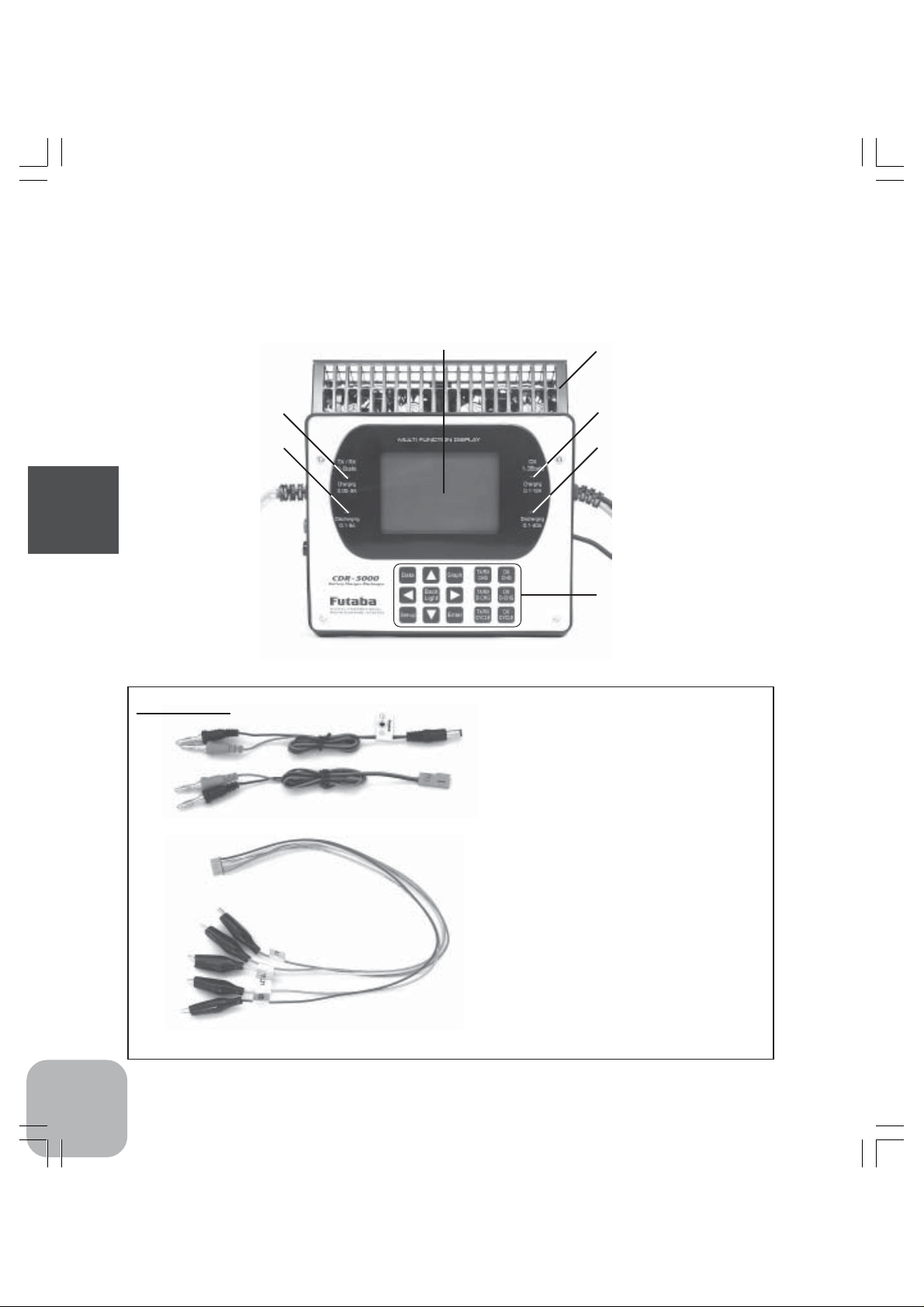
Set Contents/Nomenclature
Please check the contents of your shipment comparing to the parts shown here.
If you believe that you are missing any of these parts, please contact the distributor from whom you
purchased the system.
•LCD display
•Heat sink protector
•"TX/RX Charging"
LED
•"TX/RX Discharging"
LED
Before Using
Accessories
CDR-5000
•TX charge adaptor
*This is used for charging/discharging batteries for
transmitters. Please make sure that polarity is correct
before connecting the adaptor to TX/TR terminal of CDR-
5000.
•RX charge adaptor
*This is used for charging/discharging batteries for
receivers. Please make sure that polarity is correct before
connecting the adaptor to TX/TR terminal of CDR-5000.
•"DX Charging" LED
•"DX Discharging" LED
•Edit keys
8
•Terminal harness
*This is used for measuring characteristics of each cell in a
serially composed battery (2 - 6 cells). Connect the other
end of a terminal harness to the "Terminal Harness" on
CDR-5000.
•Conversion table sheet between Celsius
and Fahrenheit temperatures
Page 8
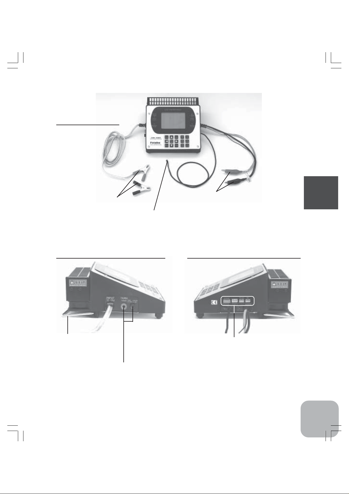
Cords equipped with
CDR-5000
•Input clips
*Connect these to the power source. Be
sure to connect in the proper polarity.
Red: positive, Black: negative
•Thermo sensor
*This is the temperature sensor of a battery that is used for
monitoring a battery characteristics and stopping charging/
discharging at a certain level.
View from the left side of CDR-5000
•Stand
*Always spread this stand
while charging/discharging
for cooling
•TX/RX charge adaptor terminal
*Red: positive, Black: negative: Please give full
attention to the polarity.
•Output clips
*Connect these to a battery for motors. Be sure to connect in
the proper polarity. Red: positive, Black: negative
View from the right side of CDR-5000
•Terminal Harness connector
•Thermo stand connector
(Thermo stand is sold separately.)
•Printer connector
(This is for factory use only.)
•PC connector
(This is for factory use only.)
Before Using
9
Page 9
CDR-5000 Functions
Map of Functions
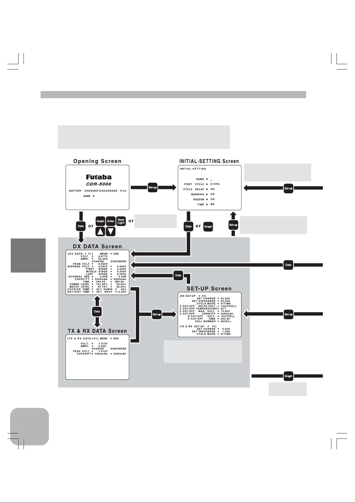
Connect the input cords of CDR-5000 to the power source
and switch on the power source, and then CDR-5000 will
automatically turn on and show its opening screen.
Keep the button pressed until
INITIAL-SETTING screen
shows up.
CDR-5000 Functions
When a battery is
connected.
SET-UP screen will return to Data
screen or Graph screen automatically about one minute after no key
operation is done.
Keep the button pressed until
INITIAL-SETTING screen
shows up.
Graph 1 screen
is shown.
10
Page 10
Use "Graph" or " " key to
advance to the next screen
and use " " key for re verse.
CDR-5000 Functions
11
Page 11
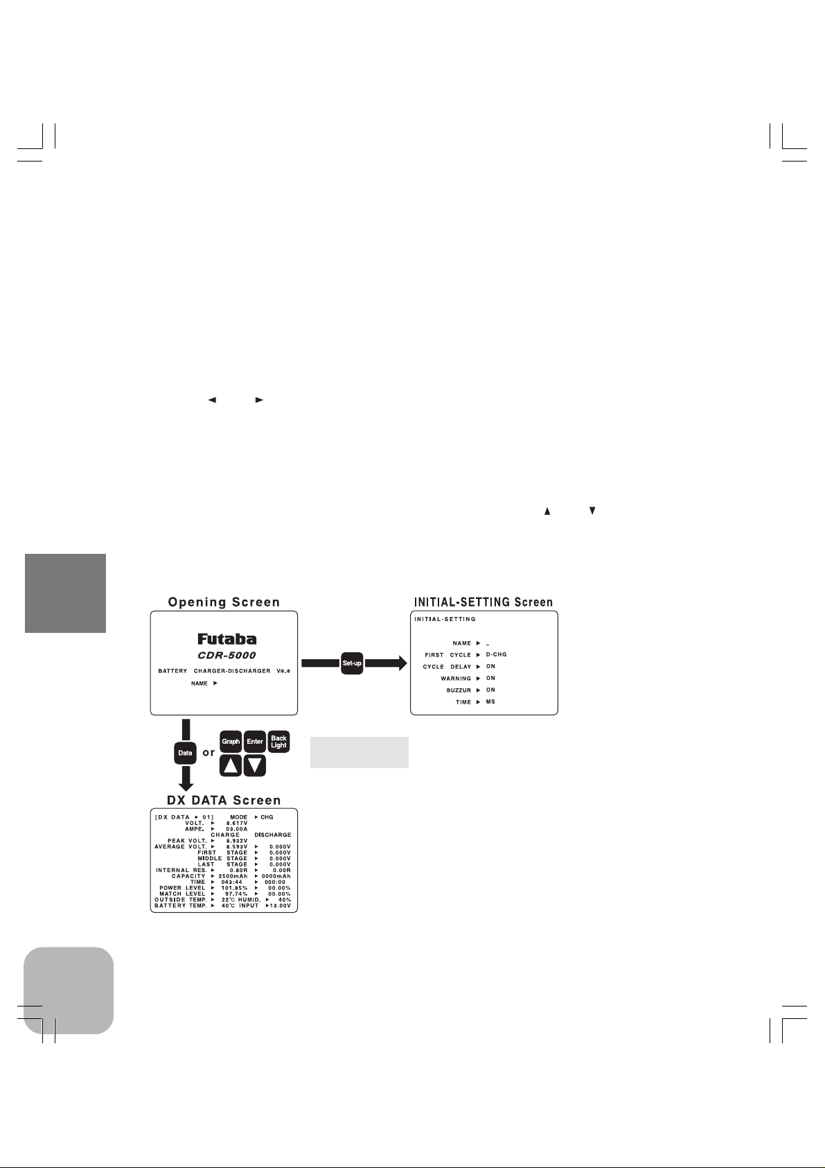
Opening Screen
Connect the input cord of CDR-5000 to a power source, and then CDR-5000 will be automatically
turned on and show its opening screen with a buzzer (one beep sound).
*It is recommended to use a 12V car battery with a capacity of 40Ah or larger or a DC power supply of 12V to 16V with a
current capacity of 15A or larger as a power source. See page 2 for power source precautions.
*If the BUZZER is set to "OFF" in the INITIAL-SETTING, there will be no sound.
*If the voltage of the power source is over 16 volts (or lower than 12 volts) or the polarity of the input cord is connected in a
wrong way, CDR-5000 will not be turned on. In such a case, check the output voltage of the power source.
*The warning message "RELAY DAMAGE SERVICE 01!!" if it is shown on the screen, means that CDR-5000 is out of order
due to some reason. Please contact to the distributor from whom you purchased the system.
[How to reset the previous data]
While pushing " " and " "keys at the same time, connect the input cord to the power source and
switch on the power source, and then CDR-5000 will be reset to the status as supplied by the
factory.
[How to switch from the opening screen to another screen]
INITIAL-SETTING screen: Push "Set-up" key.
DX DATA screen: Connect a battery to the DX port or TX/RX port, then this screen will automati-
cally appear. Or push any one of "Data", "Graph", "Enter", "Back Light", " " and " " while a battery
is disconnected.
*If the screen does not show DX DATA but the warning message "INPUT POWER SUPPLY VOLTAGE IS TOO LOW!", the
output voltage of the power source is possibly too low. Please check the output voltage of the power supply.
CDR-5000 Functions
12
When a battery is
or
connected.
[Backlight for LCD screen]
You can turn on and off the back light of LCD screen by
pushing the key "Back Light".
The backlight will be turned off automatically after a certain
period of time.
To re-light the backlight, push the key "Back Light".
Page 12
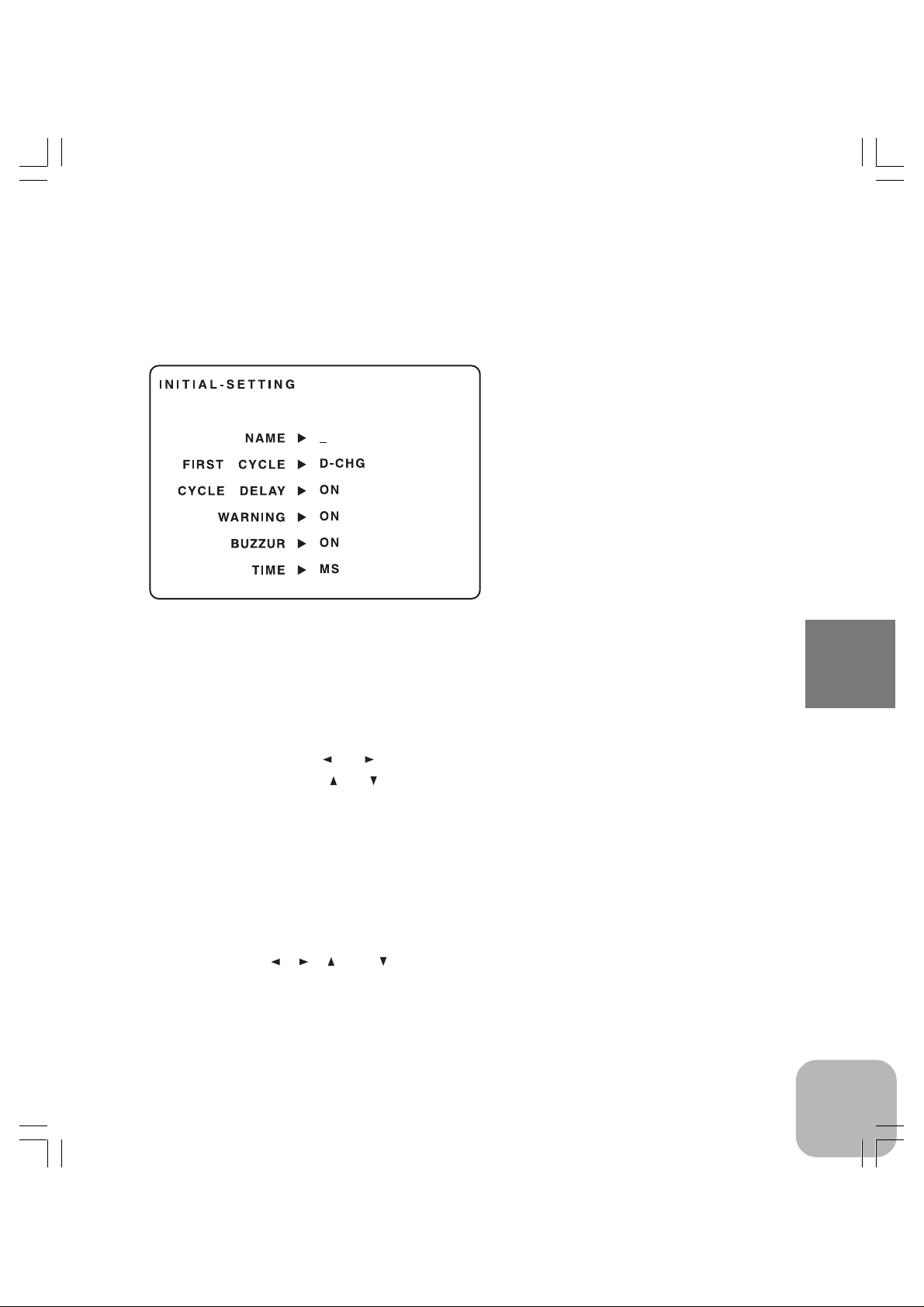
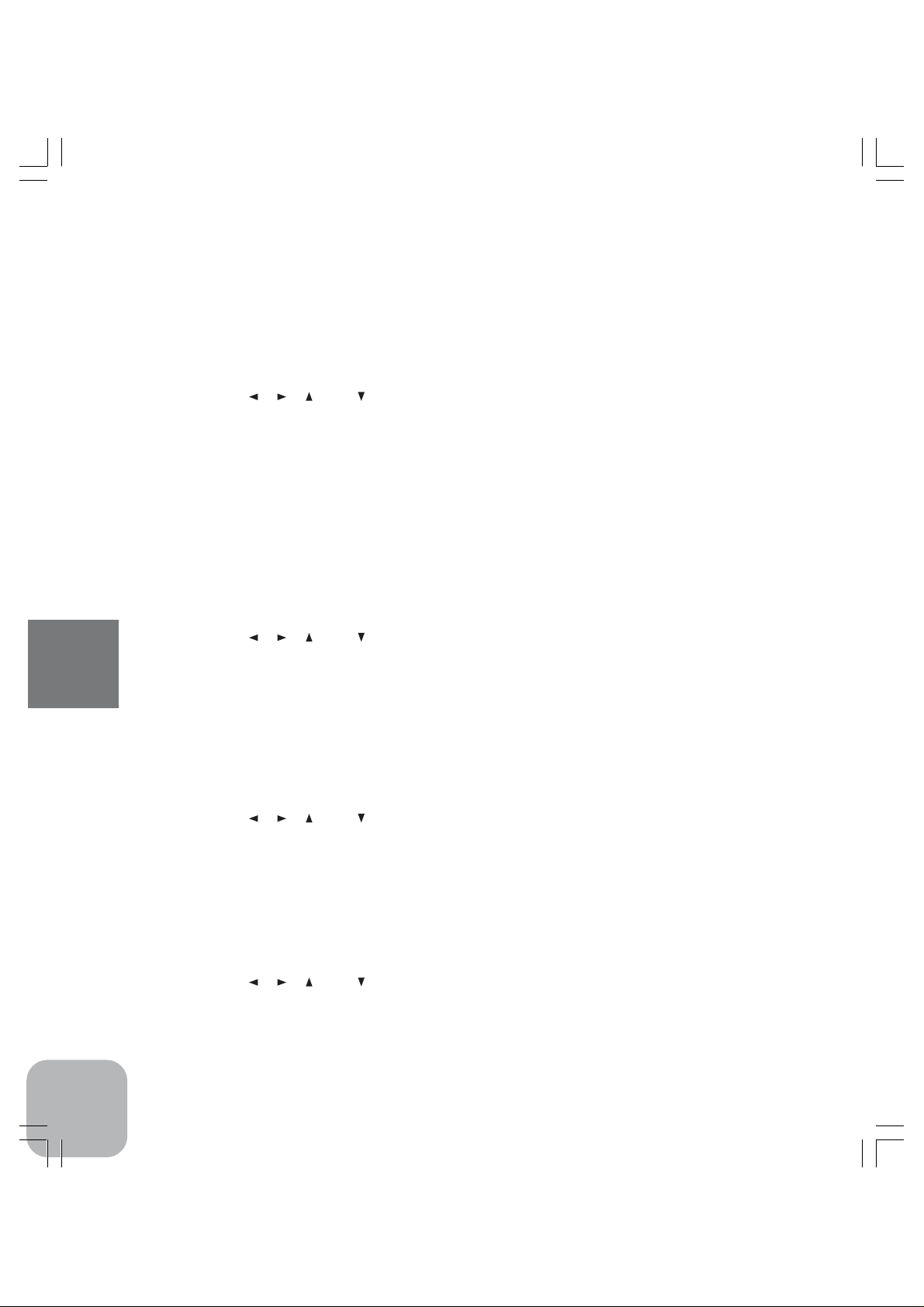
Initial-Setting Screen
Here you can set the following conditions. After completion of INITIAL-SETTING, change the screen
to DX DATA screen as described hereunder before ending operation of CDR-5000, otherwise all the
data you have set here will be lost.
[How to select an item]
Push "Enter" key to select an item to set parameter.
[How to save parameters that you
have set here]
Push "Data" key after completion of INITIALSETTING and switch to DX D A TA screen, then
all the parameters you have set will be automatically saved.
NAME
Set user's name that will be shown on the opening screen. The maximum number of characters is eight.
<Characters to be used>
ABCDEFGHIJKLMNOPQRSTUVWXYZ[¥]^`abcdefghijklmnopqrstuvwxyz!”#$%&’()*+,-./
0123456789:;<=>?@
<Operation keys>
Move cursor by pushing " " or " " keys (to select the character.)
Set character by pushing " " or " " keys.
FIRST CYCLE
You can select "Discharging" or "Charging" to start the cycle mode that repeats charging and discharging up to the preset count. The default parameter is set to "D-CHG (discharge)".
<Setting mode>
D-CHG: start from discharging
CHG: start from charging
<Operation key>
Push any one of " ", " ", " " and " " keys to select the mode.
CYCLE DELAY
This parameter sets a waiting condition in a cycle mode while the batteries are at high temperature. The
default parameter is set to "ON". This function is available only at DX.
CDR-5000 Functions
13
Page 13
<Setting mode>
ON: If the thermo stand detects the temperature over 40 degrees Celsius, the next cycle of
charging/discharging will be suspended. It restarts as soon as the temperature becomes
below 40 degrees Celsius.
OFF: Regardless with the temperature measured by the sensors, cycle mode will continue. But
the "CUT-OFF TEMPERATURE" remains effective if it has been set at SET-UP.
<Operation key>
Push any one of " ", " ", " " and " " keys to select the mode.
"CYCLE DELAY" is strongly recommended to set "ON" to keep the battery temperature as low as possible because the battery temperature tends to increase very high
during continuous cycles of charging and discharging under "CYCLE MODE".
WARNING
On the SET-UP screen, you can display confirmation messages or not by setting this parameter. The
default parameter is set to "ON".
<Setting mode>
ON: Display confirmation messages
OFF: Do not display confirmation messages
<Operation key>
Push any one of " ", " ", " " and " " keys to select the mode.
BUZZER
Set the buzzer "ON" or "OFF". The default parameter is set to "ON".
<Setting mode>
CDR-5000 Functions
ON: It buzzers when the power is turned on, when keys are operated, when charging or dis-
charging is finished.
OFF: No buzzer.
<Operation key>
Push any one of " ", " ", " " and " " keys to select the mode.
TIME
This determines the mode of time display. The default parameter is set to "MS".
<Setting mode>
MS: minute and second (00:00)
S: second (0000S)
<Operation key>
Push any one of " ", " ", " " and " " keys to select the mode.
14
Page 14

Charging/Discharging
1. Setting Parameters for Charging/Discharging
Caution: Before connecting a battery to charge/discharge it to CDR-5000, be sure to
check all parameters on the SET-UP screen and correct them if necessary. It is possible to change each parameter while charging/discharging is being conducted, however the data will become unreliable.
[How to call SET-UP screen]
While keeping the battery disconnected to the DX port,
push any of the following keys, "Data", "Graph", "Enter",
" " and " " in the opening screen to go to DX DATA screen.
Then push "Set-up" key in the DX DATA screen to SETUP screen.
[Confirmation and setting of parameters in the SET-UP screen]
DX SET-UP: This screen is for DX port. (Rapid charge/discharge batteries for motors)
TX&RX SE-UP: This screen is for TX/RX port. (Batteries for transmitters and receivers)
<Operation key>
Push "Set-up" key to s witch DX SET-UP and TX&RX SET-UP. The selected memory-number will
blink.
Push "Enter" key to select the parameter in the SET-UP screen.
Move cursor by pushing " " or " " keys (to select the digit.)
Set number by pushing " " or " " keys.
CDR-5000 Functions
15
Page 15

Items in the SET-UP screen
Caution: The setting should be carried out taking into consideration the types of batteries and the number of battery cells. Parameters used in this description are rough
targets that are mainly intended to avoid damages to batteries. These targets are not
necessarily optimal to the batteries that are used for competitions.
The term of "1C" in this manual is defined by the charging/discharging capacity of a
battery cell. For e xample , when "2400mAh" is shown on a battery cell, then "1C" for the
battery is 2.4A. When "3300mAh" is shown on a battery cell, then "1C" for the battery
is 3.3A.
[DX SET-UP]
It is possible to memorize 10 types of charging/discharging data for DX. For example, if you memorize
two types such as 4 NiMH cells with 3300mAh and 6 NiMH cells with 3300mAh, you can select one
out of two types by selecting memory number.
<Operation key>
Push " " or " " key to select the memory number.
SET CHARGE
This is to set the charging current for DX. 0.1-12A (0.01A step)
However, the maximum charging current varies according to the charging voltage. (See page 27)
* If the "WARNING" is set to "ON" on the INITIAL-SETTING", the confirmation message "CHARGE AMPERE IS TOO
HIGH!" will be shown on the screen when the current is set between 5A and 12A. If there is no error, continue setting. The
message will be shown no more than twice. Please be aware that charging at a high current may damage batteries.
* It is recommended to set the charging current somewhere between 1C and 1.5C. Here 1C is the typical capacity specified by its
manufacture. In case of charging a large number of cells, it is recommended to set the charge current within the maximum
current shown in page 27.
CDR-5000 Functions
(Example) When charging a NiCd battery of 2400mAh typical, the target charging current will be derived from the following
calculation: 2400mAh x 1.0=2.4A, 2400mAh x 1.5=3.6A
Therefore set the charging current in this case between 2.4A and 3.6A. However, in case of NiMH batteries, it is recommended
to charge at 4.0A for 3000mAh battery and 4.5A for 3300mAH battery.
When charging a large number of battery cells at a time, CDR-5000 might automatically limit the charging current or stop
charging before detecting correct delta-peak by its current overload protection circuit. Please set appropriate parameters within
the range listed in page 27 by estimating the maximum voltage and charging current.
SET DISCHARGE
This is to set the discharging current for DX. 0.1-40A (0.01A step)
However, the maximum discharging current varies according to the discharging voltage. (See page 27)
*If the "WARNING" is set to "ON" on the INITIAL-SETTING", the confirmation message "DISCHARGE AMPERE IS TOO
HIGH!" will be shown on the screen when the current is set between 10A and 40A. If there is no error, continue setting. The
message will be shown no more than twice. Please be aware that discharging at a high current may damage batteries. It is
strongly recommended to cool the battery by cooling fans when discharging over 10A.
*It is recommended to set the discharging current somewhere between 1C and 4C. Here 1C is the typical capacity specified by its
manufacture.
(Example)When discharging a battery of 3000mAh typical, the target charging current will be derived from the following
calculation: 3000mAh x 1.0=3.0A, 3000mAh x 1.5=12.0A
Therefore set the discharging current in this case between 3.0A and 12.0A.
16
Page 16

CYCLE MODE
This is to set the number of cycles of charging/discharging at DX. 1 TIME means one cycle of a
charging and a discharging. The setting range is from 1 through 99.
C CUT-OFF DELTA VOLT
This is to set the voltage for "Delta Peak" detection level to stop charging at DX port. 0DV or 3 - 5mV/
CELL (1mV/CELL step)
*If the "WARNING" is set to "ON" on the INITIAL-SETTING", the confirmation message "CUT-OFF DELTA VOLT IS TOO
HIGH!" will be shown on the screen when the voltage is set between 20mV/cell and 50mV/cell. If there is no error, continue
setting. The message will be shown no more than twice. It is recommended to set "C CUT-OFF DELTA VOLT" at 10-20mV/cell
for NiCd battery and 0DV for NiMH battery.
C CUT-OFF TEMPERATURE
This is to set the maximum temperature of the battery to stop charging at DX port. Setting range is from
25 through 75 degrees Celsius. (1 degree step)
*If the "WARNING" is set to "ON" on the INITIAL-SETTING", the confirmation message "CUT-OFF BATTERY TEMPERA-
TURE IS TOO HIGH!" will be shown on the screen when the temperature is set between 50 and 75 degrees Celsius. If there is
no error, continue setting. The message will be shown no more than twice. Please be aware that batteries may be damaged if its
temperature becomes very high. It is recommended to set this parameter below 45 degrees Celsius.
*The temperature shown on the screen may slightly differ from actual temperature around the CDR-5000. Please take this
temperature as a reference for setting CDR-5000.
C CUT-OFF MAX VOLT
This is to set the maximum voltage of the battery to stop charging at DX port. Setting range is from 0.1
through 62V. (0.001V step)
*If the "WARNING" is set to "ON" on the INITIAL-SETTING", the confirmation message "CUT-OFF MAX VOLT IS TOO
HIGH!" will be shown on the screen when the voltage is set over 13V. If there is no error, continue setting. The message will be
shown no more than twice. It is recommended to set the maximum voltage below the 1.5 times of the maximum voltage
specified by its manufacture in light of not detecting delta-peak.
(Example) When using a battery of 6 cells (1.2V/cell), set the parameter at 10.8V. (1.2V/cell x 6 cells x 1.5= 10.8V)
C CUT-OFF CAPACITY
This is to set the maximum capacity to stop charging at DX port. Setting range is from 50 through
9999mAh. (1mAh step)
*If the "WARNING" is set to "ON" on the INITIAL-SETTING", the confirmation message "CAPACITY IS TOO HIGH!" will be
shown on the screen when the capacity is set over 4000mAh. If there is no error, continue setting. The message will be shown no
more than twice. It is recommended to set the maximum voltage below the 1.3 times (1.3C) of the maximum capacity specified
by its manufacture in light of not detecting delta-peak.
D CUT-OFF VOLT
This is to set the voltage of the battery to stop discharging at DX port. Setting range is from 0.1 through
62V. (0.001V step) Or it can be set by 0.8V/cell, 0.85V/cell or 0.9V/cell.
*The voltage to stop discharging is recommended to be set at 0.8V/cell or the total voltage, 0.8V x number of cells.
(Example) In case of 6 cells: 0.8V x 6= 4.8V
D CUT-OFF TIME
This is to set the time to stop discharging at DX port. Setting range is from 10sec through 999m00sec
(=59,940sec). (1 second step) Or set the timer off.
CDR-5000 Functions
17
Page 17

CELL NUMBER
This is to set the number of battery cells that are connected to DX. Set "AUTO" or any number between
1 and 36 cells. (1 cell step)
*Select "AUTO" when used in a battery pack, and set the number when the number of cells in a battery pack is known.
*If the "WARNING" is set to "ON" on the INITIAL-SETTING", the confirmation message "CHECK YOUR CELLS NUM-
BER!" will be shown on the screen when you change the setting number of cells. If there is no error, continue setting. The
message will be shown no more than twice. If the wrong number is used, reset the correct number.
[TX&RX SET-UP]
It is possible to memorize 10 types of charging/discharging data for TX&RX. For example, if you
memorize two types such as 5 NiCd cells with 600mAh and 5 NiCd cells with 1500mAh for receivers,
you can select one out of two types by selecting memory number.
<Operation key>
Push " " or " " key to select the memory number.
SET CHARGE
This is to set the charging current at TX/RX. The setting range is from 0.05 to 2A. (0.01A step)
*Be sure that you don't charge a battery over its typical current (1C) specified by its manufacture.
(Example) When charging a battery of 1000mAh typical, the target charging current should be lower than 1A (1000mAh x
1.0=1.0A).
*Charging a battery at over 1C may cause abnormal heat generation or deterioration of the battery. Never charge a battery at over
1C especially when the battery is connected to a transmitter.
SET DISCHARGE
This is to set the discharging current at TX/RX. The setting range is from 0.1 to 5A. (0.01A step)
However, the maximum discharging current varies according to the discharging voltage. (See page 27)
*It is recommended that discharging current is in the range between 1C and 2C. Here 1C is the typical capacity specified by its
CDR-5000 Functions
manufacture.
(Example) When discharging a battery of 1000mAh typical, the target discharging current should be between 1.0A and 2.0A
(1000mAh x 1.0=1.0A, 1000mAH x 2.0=2.0A).
*Discharging a battery at very high current may cause abnormal heat generation or deterioration of the battery. Before discharg-
ing the battery of a transmitter, be sure to disconnect the battery from the transmitter. The CDR 5000 is not applicable for
discharging those batteries with protection circuit. (Examples: NT-8A, NT8S1100 for T9Z and so on.)
CYCLE MODE
This is to set the number of cycle times of charging/discharging at TX/RX. 1 TIME means one cycle of
a charging and a discharging. The setting range is from 1 through 99.
18
Page 18

2. Connecting Battery
Caution: Ne v er charge or discharge an y batteries other than NiCd and NiMH batteries.
Charging or discharging the batteries other than NiCd and NiMH batteries may cause
abnormally high heat generation and fire.
Preparation: After selection of memor y numbers, settings of all parameters and final
confirmation on the SET-UP screen push "Data" key to get DX-DATA screen. Pushing
"Data" key from DX DATA screen can access TX&RX DATA screen.
1)Set DX DATA number or TX&RX DATA number to "01"
by using " " and " " keys.
*Make the Thermo Sensor contact to the battery when charging at DX
terminal. If you have Thermo Stand (option), lay the battery on the Thermo
Stand (not applicable for batteries with 7cells and more and straight packs)
instead of using Thermo Sensor. Thermo Sensor and Thermo Stand are not
applicable to batteries at TX/RX.
2)Connect a battery to the output port that should be w ell
matched to the battery type. Make sure that the polarity is
correct.
Caution: In case of discharging a battery of a
transmitter, do not try to discharge the battery
while it is connected to the transmitter. A protection circuit in a transmitter will prev ent it. The
CDR 5000 is not applicable for discharging those
batteries with protection circuit. (Examples: NT8A, NT8S1100 for T9Z and so on.)
*DX port: This port is for the batteries for motors that require rapid charging
and discharging.
*TX/RX port: This port is for batteries for transmitters and receivers.
*DX and TX/RX ports of CDR-5000 can be used simultaneously
CDR-5000 Functions
3)MODE indication changes from "NO BAT." to "READY".
*If "SHORT" is displayed in MODE, please check the possibility of reversal connection of a battery, electrical short and over-
discharge. If the "WARNING" is set to "ON" on the INITIAL-SETTING", the warning message "SHORT OR REVERCE!" will
be shown on the screen.
4)Use Terminal Harness for obtaining the each cell data of a battery connected to DX terminal.
Be sure to connect DX terminal first before connecting Terminal Harness.
*In case of using Terminal Harness, it is necessary to input the exact number of cells in the "CELL NUMBER" on the SET-UP
screen.
19
Page 19
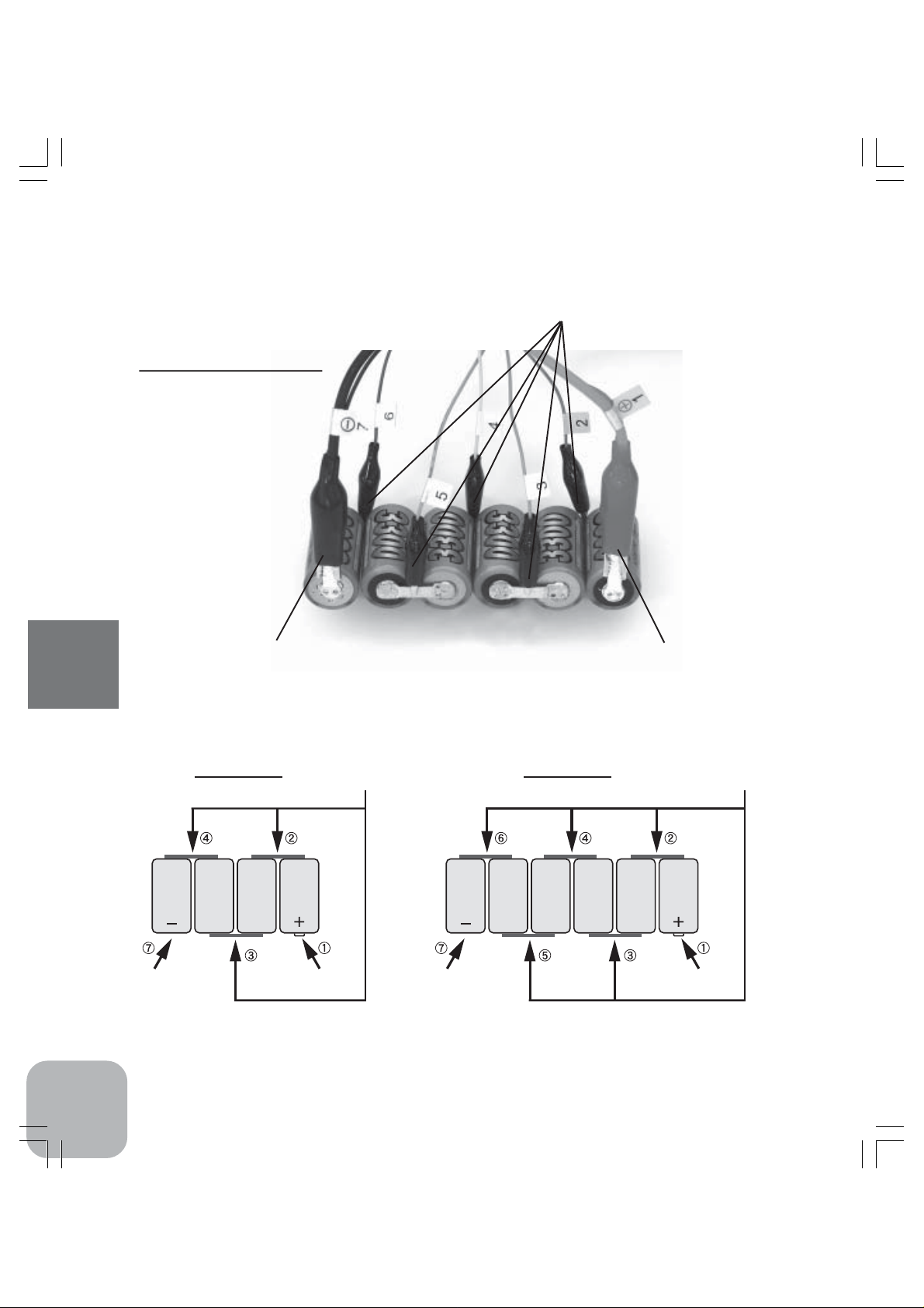
DX Terminal
/Terminal Harness
•Terminal Harness
*Connect Terminal Harness as shown here.
•DX Terminal (-)
*Black: negative
CDR-5000 Functions
(4 cells) (6 cells)
•DX Terminal (-)
20
•Terminal
Harness
•DX Terminal (+)
*Red: positive
•Terminal
Harness
•DX Terminal (-)•DX Terminal (+) •DX Terminal (+)
Page 20

3. Start of Charging/Discharging
[Charging at DX]
1)Push "DX CHG" key.
2)The red LED of "DX Charging" turns on. MODE indicator changes from "READY" to "CHG".
And charging will start.
[Discharging at DX]
1)Push "DX D-CHG" key.
2)The blue LED of "DX Discharge" turns on. MODE indicator changes from "READY" to "DCHG". And discharging will start.
*It is strongly recommended to cool the battery by cooling fans when discharging over 10A.
[Charging at TX/RX]
1)Push "TX/RX CHG" key.
2)The red LED of "TX&RX Charging" turns on. MODE indicator changes from "READY" to "CHG".
And charging will start.
[Discharging at TX/RX]
1)Push "TX/RX D-CHG" key.
2)The blue LED of "TX/RX Discharge" turns on. MODE indicator changes from "READY" to "DCHG". And discharging will start.
Caution for discharging: Sensing the v oltage of the battery while discharging at TX&RX,
CDR-5000 automatically calculates the voltage level that stops discharging. It suggests that if you discharge a battery that has been already discharged or a battery
whose voltage is already very low, the battery will be over-discharged. Never do an
additional discharging
If the voltage of a battery under discharging declines in the early stage and becomes
lower than 0.8V/cell, stop discharging.
It is recommended to use a cooling fan to keep the temper ature of a battery low while
discharging in Cycle Mode, because the temperature of the battery under Cycle Mode
generate a large amount of heat due to continuous operation. And it is also recommended that "CYCLE DELAY" in the "INITIAL SETTING" be set "ON" during the usage.
CDR-5000 Functions
21
Page 21

4. End of Charging/Discharging
[End of charging at DX]
Alarm buzzer will beep as soon as charging at DX is over. And "FINISHED DX CHARGE" screen will
be shown. The red LED of "DX Charging" is turned off. Charging process is now completed.
*If the "BUZZER" is set to "OFF" in the "INITIAL SETTING", there will be no alarm buzzer.
<How to return to "DX DATA" screen>
Push "Data" key to return to "DX DATA"
screen from "FINISHED DX CHARGE"
screen.
CUTOFF BY
This is show the item that is detected at first among the items related to CHARGE CUT in the "SETUP" screen.
CDR-5000 Functions
*DELTA PEAK (0 DELTA VOLT.): When DELTA PEAK was used for CHARGE CUT.
*TEMP: When battery temperature was used for CHARGE CUT.
*VOLT: When the maximum voltage was used for CHARGE CUT.
*CAPA: When charging capacity was used for CHARGE CUT.
*LOW DC 12V: When the voltages drop of a power source was used as a parameter for CHARGE CUT.
POWER LEVEL
This is the number that represents the status of a battery under charging by calculating from the voltage
drop of the battery to which a certain constant load is applied. The bigger the number is, the better the
condition of the battery is. Take into consideration this number as a guide for daily maintenance of
batteries. The maximum is 120%.
FINISHING BATTERY TEMP
This shows the temperature of a battery when the charging of the battery is completed.
22
Page 22

[End of discharging at DX]
Alarm buzzer will beep as soon as discharging at DX is over. And "FINISHED DX DISCHARGE"
screen will be shown. The blue LED of "DX Discharging" is turned off. Discharging process is now
completed.
*If the "BUZZER" is set to "OFF" in the "INITIAL SETTING", there will be no alarm buzzer.
<How to return to "DX DATA" screen>
Push "Data" key to return to "DX DATA"
screen from "FINISHED DX DISCHARGE"
screen.
CUTOFF BY
This shows the item that is detected at first among the items related to DISCHARGE CUT in the "SETUP" screen.
*VOLT: When the voltage level was used for DISCHARGE CUT.
*TIMER: When timer was used for DISCHARGE CUT.
POWER LEVEL
This is the number that represents the status of a battery under discharging by calculating from the
voltage drop of the battery to which a certain constant load is applied. The bigger the number is, the
better the condition of the battery is. Take into consideration this number as a guide for daily maintenance of batteries. The maximum is 120%.
FINISHING BATTERY TEMP.
This shows the temperature of a battery when the discharging of the battery is completed.
CDR-5000 Functions
23
Page 23
[End of charging at RX/TX]
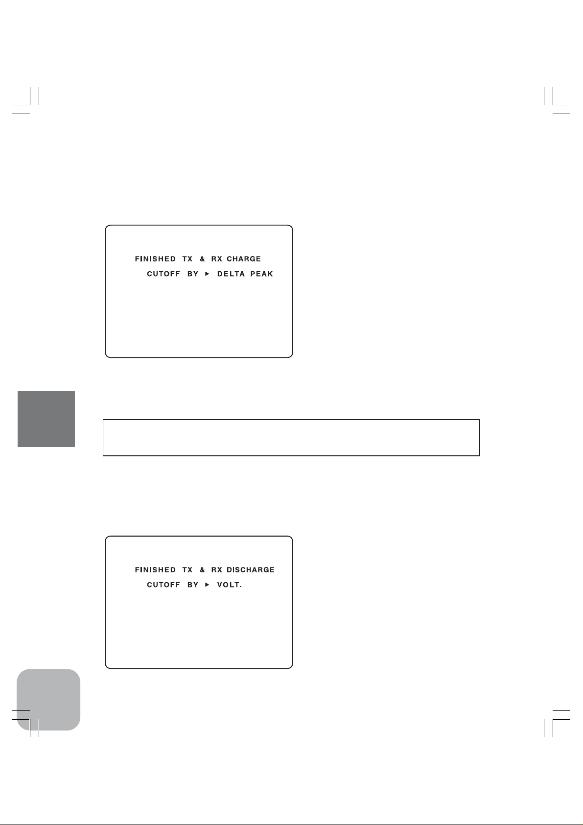
Alarm buzzer will beep as soon as the charging at TX/RX port is over without fail after detecting
"DELTA PEAK". And "FINISHED TX & RX CHARGE" screen will be shown. The red LED at TX/
RX is turned off. Charging process is now completed.
*If the "BUZZER" is set to "OFF" in the "INITIAL SETTING", there will be no alarm buzzer.
<How to return to "TX&RX DATA" screen>
Push "Data" key to move to "DX DATA"
screen from "FINISHED TX & RX
CHARGE" screen, then push "Data" key
again to return to "TX&RX DATA" screen.
CUTOFF BY
This shows a detected item such as bellow.
*DELTA PEAK: This message will be shown when CHARGE CUT is carried out in proper way by "DELTA PEAK".
*LOW DC 12V: This message will be shown when CHARGE CUT is carried out by the drop of a power source.
Caution: If the output voltage increases abnormally, charging will be forced to stop as
the "FINISHED TX & RX CHARGE" screen will not be shown, MODE indicator changes
CDR-5000 Functions
from "CHARGE" to "READY" with an alarm buzzer.
[End of discharging at TX/RX]
Alarm buzzer will beep as soon as discharging at TX/RX is over. And the "FINISHED TX & RX
DISCHARGE" screen will be shown. The blue LED at TX/RX is turned off. Discharging process is
now completed.
*If the "BUZZER" is set to "OFF" in the "INITIAL SETTING", there will be no alarm buzzer.
<How to return to "TX&RX DATA" screen>
Push "Data" key to move to "DX DATA"
screen from "FINISHED TX & RX DISCHARGE" screen, then push "Data" key
again to return to "TX&RX DATA" screen.
24
Page 24

5. Cycle Charging/Discharging
[Cycle Charging/Discharging at DX]
1)Push "DX CYCLE" key.
2)Either the blue LED of "DX Discharging" or the red LED of "DX Charging" turns on. MODE
indicator changes from "READY" to "CYCLE01". And charging or discharging will start.
*The cycle starts with the mode that is preset by the "FIRST CYCLE" in the "INITIAL SETTING". (D-CHG: start from
discharging, CHG: start from charging)
3)When the starting mode is over, "FINISHED---" screen is shown and the next mode starts.
When the cycle mode is over, "FINISHED---" screen will be shown again. (One cycle means a
discharge and a charge or a charge and a discharge.)
*If the "CYCLE DELAY" is set to "ON" in the "INITIAL SETTING", the next charging/discharging mode will not be carried out
as long as the Thermo Stand reads the temperature higher than 40 degrees Celsius. However, the next charging/discharging mode
will restart again if the temperature goes down below 40 degrees Celsius.
4)If the cycle time is set at 2 times or more, the MODE indication will change from "CYCLE 2" to
"CYCLE 3" and so on after the first one cycle.
5)As soon as the Cycle Charging/Discharging is over, "FINISHED---" screen of either Charge or
Discharge will be shown. Those screens are exactly same as those shown in the single Charge
and Discharge modes.
<How to return to "DX DATA" screen>
Push "Data" key to return to "DX DATA" screen from "FINISHED---" screen.
[Cycle Charging/Discharging at TX/RX]
1)Push "TX/RX CYCLE" key.
2)Either the blue LED of "TX/RX Discharging" or the red LED of "TX&RX Charging" turns on.
MODE indicator changes from "READY" to "CYCLE01". And charging or discharging will start.
*The cycle starts with the mode that is preset by the "FIRST CYCLE" in the "INITIAL SETTING". (D-CHG: start from
discharging, CHG: start from charging)
3)When the starting mode is over, "FINISHED---" screen is shown and the next mode starts.
When the cycle mode is over, "FINISHED---" screen will be shown again. (One cycle means a
discharge and a charge or a charge and a discharge.)
*The "CYCLE DELAY" that is defined in the "INITIAL SETTING" is not applicable at TX/RX.
4)If the cycle time is set at 2 times or more, the MODE indication will change from "CYCLE 2" to
"CYCLE 3" and so on after the first one cycle.
5)As soon as the Cycle Charging/Discharging is over, "FINISHED---" screen of either Charge or
Discharge will be shown. Those screens are exactly same as those shown in the single Charge
and Discharge modes.
<How to return to "TX&RX DATA" screen>
Push "Data" key to mov e to "DX DATA" screen from "FINISHED---" screen, then push "Data" key
again to return to "TX&RX DATA" screen.
CDR-5000 Functions
25
Page 25

6. Compulsively End of Charging/Discharging
[How to stop charging on the way at DX]
Push any one of the keys of "DX CHG", "DX D-CHG" and "DX CYCLE" in order to intentionally
stop charging on the way at DX. Then the MODE indicator changes from "CHG" to "READY" and
the red LED of "DX Charging" turns off with a single beep.
*If the "BUZZER" is set to "OFF" in the "INITIAL SETTING", there will be no alarm buzzer.
[How to stop discharging on the way at DX]
Push any one of the keys of "DX CHG", "DX D-CHG" and "DX CYCLE" in order to intentionally
stop discharging on the way at DX. Then the MODE indicator changes from "D-CHG." to "READY"
and the blue LED of "DX Discharging" turns off with a single beep.
*If the "BUZZER" is set to "OFF" in the "INITIAL SETTING", there will be no alarm buzzer.
[How to stop cycle charging/discharging on the way at DX]
Push any key of "DX CHG", "DX D-CHG" and "DX CYCLE" in order to intentionally stop charging
or discharging on the way at DX. Then the MODE indicator changes from "CHG" or "D-CHG." to
"READY" and either of the red LED of "DX Charging" or the blue LED of "DX Discharging" turns
off with a single beep.
*If the "BUZZER" is set to "OFF" in the "INITIAL SETTING", there will be no alarm buzzer.
[How to stop charging on the way at TX/RX]
Push any key of "TX&RX CHG", "TX&RX D-CHG" and "TX&RX CYCLE" in order to intentionally
stop charging on the way at TX&RX. Then the MODE indicator changes from "CHG" to "READ Y"
and the red LED of "TX/RX Charging" turns off with a single beep.
*If the "BUZZER" is set to "OFF" in the "INITIAL SETTING", there will be no alarm buzzer.
CDR-5000 Functions
[How to stop discharging on the way at TX/RX]
Push any one of the keys of "TX&RX CHG", "TX&RX D-CHG" and "TX&RX CYCLE" in order to
intentionally stop discharging on the way at TX&RX. Then the MODE indicator changes from "DCHG." to "READY" and the blue LED of "TX/RX Discharging" turns off with a single beep.
* If the "BUZZER" is set to "OFF" in the "INITIAL SETTING", there will be no alarm buzzer.
[How to stop cycle charging/discharging on the way at TX&RX]
Push any key of "TX&RX CHG", "TX&RX D-CHG" and "TX&RX CYCLE" in order to intentionally
stop charging on the way at TX&RX. Then the MODE indicator changes from "CHG" or "DCHG." to "READY" and either of the red LED of "TX/RX Charging" or the blue LED of "TX/RX
Discharging" turns off with a single beep.
* If the "BUZZER" is set to "OFF" in the "INITIAL SETTING", there will be no alarm buzzer.
Caution: Even if charging or discharging is stopped at DX and TX/RX, "STAND-BY"
mode is still effective until the battery will be disconnected. If you restart charging or
discharging from that status as it is, CDR-5000 will start operation based on that data.
Howev er , if the operation is stopped in Cycle mode , CDR-5000 restarts from CYCLE01.
Disconnecting a battery will end the measurement of data.
26
Page 26

Over Current Protection
Although the values of charging and discharging current can be set in the "SET-UP" screen, the actual
current during charging or discharging a battery will be limited in accordance with the voltage measured at the battery terminals by the "Over Current Protection" of CDR-5000.
[Charging current limit at DX]
Although the value of charging current at DX can be set at 0.1A to 12A in the "SET-UP" screen, the
actual charging current will vary depending on a battery voltage measured at its terminals.
18V or less : 12A Max
27V or less : 8A Max
36V or less : 6A Max
43V or less : 5A Max
54V or less : 4A Max
62V or less : 3A Max
[Discharging current limit at DX]
Although the value of discharging current at DX can be set at 0.1A to 40A in the "SET-UP" screen, the
actual discharging current will vary depending on a battery voltage measured at its terminals.
2.4V or less : smaller than 40A
7.5V or less : 40A Max
8.5V or less : 35A Max
10V or less : 30A Max
12V or less : 25A Max
15V or less : 20A Max
20V or less : 15A Max
30V or less : 10A Max
40V or less : 7.5A Max
50V or less : 6A Max
60V or less : 5A Max
greater than 60V : 4A Max
[Charging current limit at TX/RX]
The value of charging current at TX/RX can be set at 0.05A to 2A in the "SET-UP" screen, and the
actual charging current will be nearly equal to the set value regardless of a battery voltage measured at
its terminals.
[Discharging current limit at TX/RX]
Although the value of discharging current at TX/RX can be set at 0.1A to 5A in the "SET-UP" screen,
the actual discharging current will vary depending on a battery voltage measured at its terminals.
10V or less : 5A Max
greater than 10V : 3A Max
CDR-5000 Functions
27
Page 27
Data Screen
Up to ten of "DATA" screens including the data of charging and discharging can be memorized from the
start and the end of using CDR-5000. Switching off CDR-5000 will clear all the data.
<How to switch "DATA" screen>
"DX DATA" screen and "TX&RX DATA" screen can be obtained by pushing "Data" key.
1. DX DATA screen
[DX DATA --]
DX DATA 01 though 10 represent the data used for DX port. (*DX DATA: The content displayed on
the screen differs from 01 and the others, which are 02 through 10.)
In charge mode, the data in the column of "CHARGE" alone will be shown. And in discharge mode, the
data in the column of "DISCHARGE" alone will be shown. In case of cycle mode, the data of one cycle
in the column of "CHARGE" and "DISCHARGE" will be shown at a time on the same screen. "01"
represents the current cycle. "02" represents the previous cycle. "03" represents the two previous cycle.
And so on. If the cycle mode has been carried out at the latest, the charge and discharge data of the last
cycle will be shown in the "DX DATA 01". And the data of the previous cycle will be shown in the "DX
DA TA 02".
<How to operate>
Operate " " and " " keys to get the DATA number.
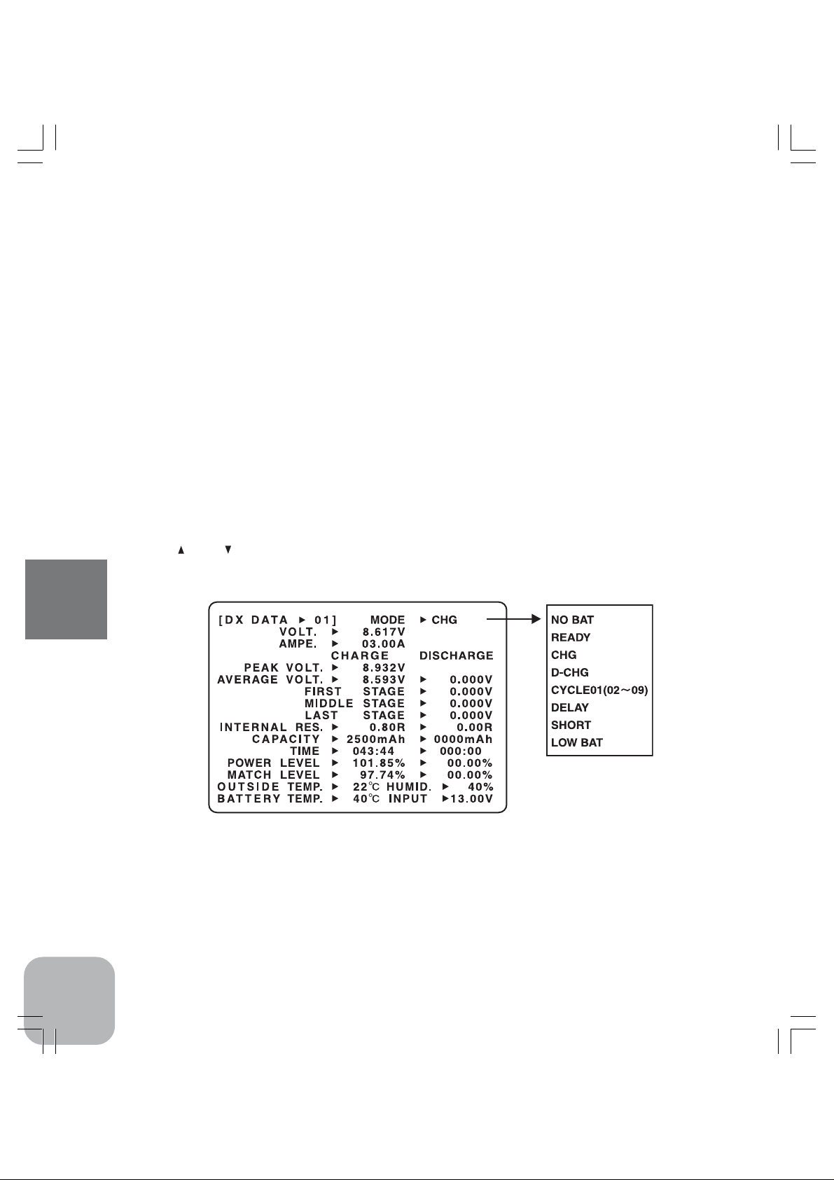
[Contents of DX DATA01]
CDR-5000 Functions
MODE
This indicates conditions of a battery for charging or discharging.
NO BAT: No battery is connected.
READY: A battery is connected. Ready to start charging or discharging.
CHG: The battery is now under charging.
D-CHG: The battery is now under discharging.
CYCLE01-99: Cycle charging/discharging is now under operation.
28
Page 28

DELAY: CDR-5000 in cycle mode is now waiting to restart again because the temperature measured by the Thermo
Stand is still over 40 degrees Celsius.
SHORT: This includes reverse connection of a battery, electrical short, over-discharge and electrical short at DX port
of CDR-5000.
LOW BAT: when the output voltage of a power source drops while charging.
VOLT.
This shows the voltage of the battery that is currently connected.
AMPE.
This shows the present charging current or discharging current. Minus symbol "-" will be attached to
the number in case of discharging mode.
PEAK VOL T .
This shows the peak voltage of a battery that is obtained while the battery is charged.
AVERAGE VOLT.
This shows the average voltage of a battery that is obtained while the battery is charged or discharged.
FIRST STAGE
This shows the estimated average voltage of a battery at an early stage of discharging process by using
the time consumed for discharging from the beginning to the end.
MIDDLE STAGE
This shows the estimated average voltage of a battery at a middle stage of discharging process by using
the time consumed for discharging from the beginning to the end.
LAST STAGE
This shows the estimated average voltage of a battery at a late stage of discharging process by using the
time consumed for discharging from the beginning to the end.
INTERNAL RES.
This shows the internal resistance of the battery that is under charging or discharging.
CAPACITY
This shows the accumulated amount of charge or discharge that has been charged or discharged from
the beginning.
TIME
This shows the accumulated amount of time from the start of charging or discharging.
POER LEVEL
This is the number that represents the status of a battery under charging or discharging by calculating
from the voltage drop of the battery to which a certain constant load is applied. The maximum is 120%.
MATCH LEVEL
This shows the matched level among the battery cells how the cells are well matched to each other in
terms of their characteristics.
CDR-5000 Functions
29
Page 29

OUTSIDE TEMP .
This shows the temperature measured by Thermo Sensor utilized in CDR-5000.
HUMID
This shows the humidity near the CDR-5000.
BATTER Y TEMP .
This shows the temperature measured by Thermo Sensor. If Thermo Stand (option) is used, this shows
the temperature measured by Thermo Stand.
INPUT
This shows the voltage of the power source.
[Contents of DX DATA02 -10]
CDR-5000 Functions
SET AMPERE
This shows the current for charging or discharging set in the "SET-UP".
CUT -OFF V OL T .
This shows the voltage to stop charging or discharging set in the "SET-UP".
PEAK VOL T .
This shows the peak voltage of a battery that is obtained while the battery is charged.
AVERAGE V OL T .
This shows the average voltage of a battery that is obtained while the battery is charged or discharged.
FIRST STAGE
This shows the estimated average voltage of a battery at an early stage of discharging process by using
the time consumed for discharging from the beginning to the end.
30
Page 30

MIDDLE STAGE
This shows the estimated average voltage of a battery at a middle stage of discharging process by using
the time consumed for discharging from the beginning to the end.
LAST STAGE
This shows the estimated average voltage of a battery at a late stage of discharging process by using the
time consumed for discharging from the beginning to the end.
INTERNAL RES.
This shows the internal resistance of the battery that is under charging or discharging.
CAPACITY
This shows the accumulated amount of charge or discharge that has been charged or discharged from
the beginning.
TIME
This shows the accumulated amount of time from the start of charging or discharging.
POER LEVEL
This is the number that represents the status of a battery under charging or discharging by calculating
from the voltage drop of the battery to which a certain constant load is applied. The maximum is 120%.
MATCH LEVEL
This shows the matched level among the battery cells how the cells are well matched to each other in
terms of their characteristics.
AVE.BAT.TEMP.
This shows the average temperature of the battery measured by Thermo Sensor or Thermo Stand.
CDR-5000 Functions
31
Page 31
2. TX & RX DATA Screen
[TX&RX DATA --]
TX&RX DATA 01 though 10 represent the data used for TX&RX port. (*TX&RX DATA: The content
displayed on the screen differs from 01 and the others, which are 02 through 10.) "01" represents the
current cycle. "02" represents the previous cycle. "03" represents the two previous cycle. And so on. If
the cycle mode has been carried out at the latest, the charge and discharge data of the last cycle will be
shown in the "TX&RX DATA 01". And the data of the previous cycle will be shown in the "TX&RX
DA TA 02".
<How to operate>
Operate " " and " " keys to get the DATA number.
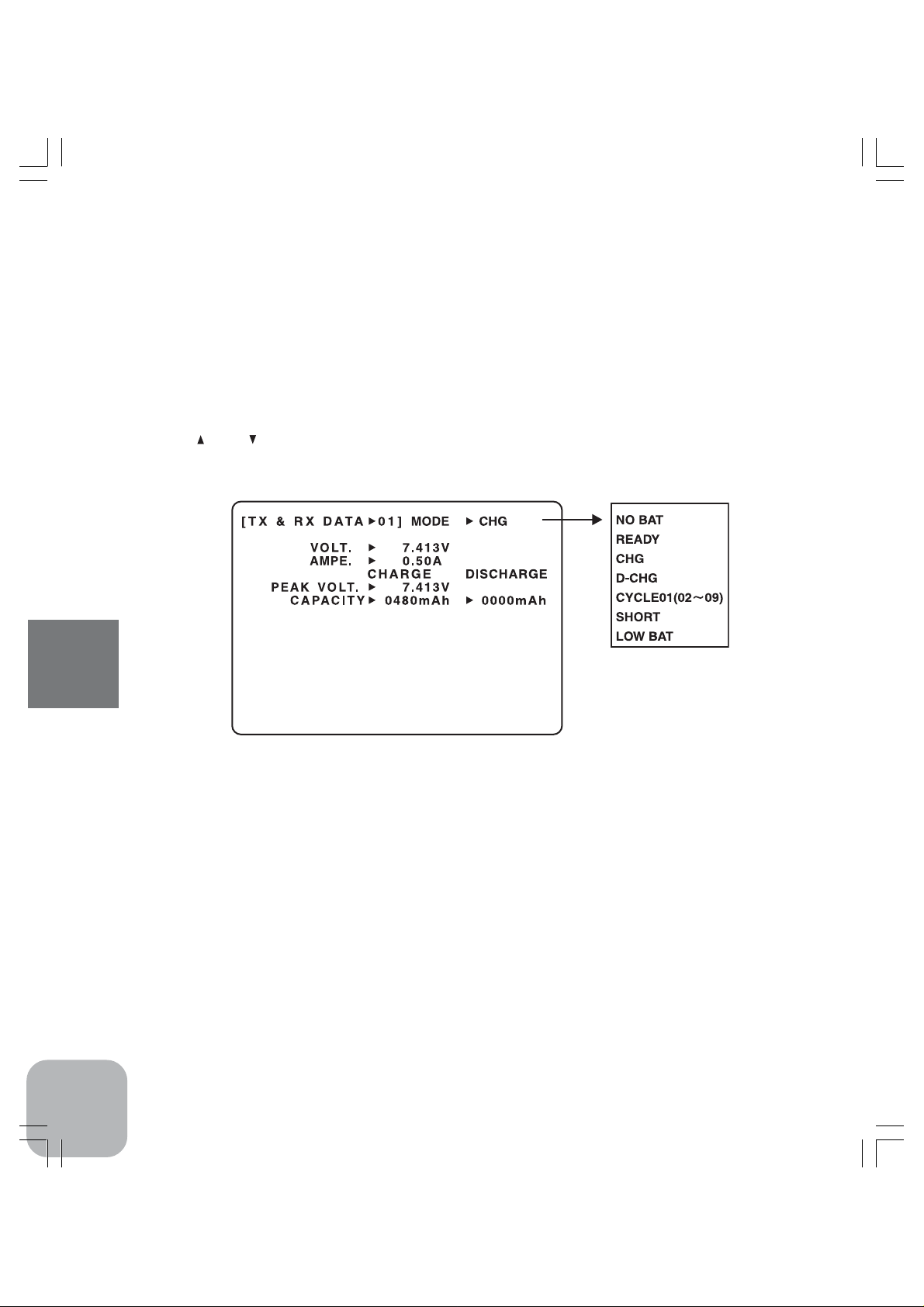
[Contents of TX&RX DAT01]
CDR-5000 Functions
MODE
This indicates the condition of a battery that is to be charged or discharged.
NO BAT: No battery is connected.
READY: A battery is connected. Ready to start charging or discharging.
CHG: The battery is now under charging.
D-CHG: The battery is now under discharging.
CYCLE01-99: Cycle charging/discharging is now under operation.
SHORT: This includes reverse connection of a battery, electrical short, over-discharge and electrical short at TX&RX
port of CDR-5000.
LOW BAT: when the output voltage of a power source drops while charging.
VOLT.
This shows the voltage of the battery that is currently connected. In the discharge mode, it shows the
voltage at the end of a discharging event.
AMPE.
This shows the present charging current or discharging current. Minus symbol "-" will be attached to
the number in case of discharging mode.
32
Page 32

PEAK VOL T .
This shows the peak voltage of a battery that is obtained while the battery is charged. Or the voltage of
the battery to stop discharging.
CAPACITY
This shows the accumulated amount of charge or discharge that has been charged or discharged from
the beginning.
[Contents of TX&RX DATA02-10]
SET AMPERE
This shows the current that is preset for charging or discharging at the "SET-UP".
PEAK VOL T .
This shows the peak voltage of a battery that is obtained while the battery is charged. Or the voltage of
the battery to stop discharging.
CAPACITY
This shows the accumulated amount of charge or discharge that has been charged or discharged from
the beginning.
CDR-5000 Functions
33
Page 33

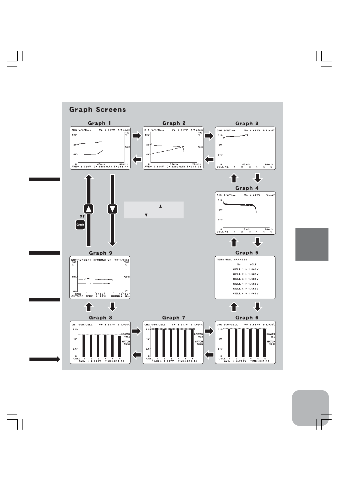
Graph Screen
Graphs are available for the data of charging or discharging under operation at DX or the data of the
end of the last operation at DX.
Even if the battery is disconnected from the DX port, the data on the screen will not be cleared. But the
data on the screen will be reset by newly connecting a battery.
Switching off CDR-5000 will clear all the data.
<How to operate>
Push "Graph" key in the "DX DATA" screen to move to "GRAPH Screen Page1".
9 types of screens are available and can be selected by using "Graph", " " and " " keys.
[GRAPH Screen Page 1 (CHG V-ºC/Time)]
This graph shows the relationship between the charging time, battery voltage and its temperature.
(Applicable for a battery of 1 to 36 cells) Although no graphs will be shown during discharging, the
CDR-5000 Functions
graph of the previous charging graph will be shown after charging is completed in cycle mode.
*The messages on the top of the screen are (from left to right):
Graph type or charging current appears alternatively. (while charging)
V: output voltage
B.T: temperature of the battery
The messages on the bottom of the screen are (from left to right):
AVE: an average voltage at charging
C: charged amount
T: time consumed for charging
<How to operate>
A cursor line vertical to the time axis will appear by pushing " " key.
The cursor line can be moved left and right by pushing " " and " " keys.
*The messages at the bottom of the screen will change when the cursor line appears.
From left to right on the bottom of the screen:
D.L. : output voltage
B.T. : battery temperature
T : the time at the crossing point between the cursor and the time axis
D.L. and B.T. are represented by values measured at the time T. In addition, D.L. and B.T. are represented by the
minimum value and maximum value respectively taken at vicinity of the time T. If the minimum value is not equal to
the maximum value, those values will be shown on the screen one after the other.
34
Page 34

Pushing " " and " " keys simultaneously will erase the cursor and move back to the screen of
"AVE", "C" and "T".
Pushing "Graph" or " " key in the "GRAPH Screen P age1" will sho w the "GRAPH Screen Page2".
Pushing " " will show "GRAPH Screen Page9".
[GRAPH Screen Page 2 (DIS V-ºC/Time)]
Pushing "Graph" or " " key in the "GRAPH Screen P age1" will sho w the "GRAPH Screen Page2".
This graph shows the relationship between the discharging time, battery voltage and its temperature.
(Applicable for a battery of 1 to 36 cells) Although no graphs will be shown during charging, the graph
of the previous discharging graph will be shown after discharging is completed in cycle mode.
*The messages on the top of the screen are (from left to right):
Graph type and discharging current appears alternatively. (while discharging)
V: output voltage
B.T: temperature of the battery
The messages on the bottom of the screen are (from left to right):
AVE: an average voltage at discharging
C: discharged amount
T: time consumed for discharging
F: average voltage at first stage
M: average voltage at middle stage
L: average voltage at last stage
These values will be shown on the screen alternatively.
<How to operate>
A cursor line vertical to the time axis will appear by pushing " " key.
The cursor line can be moved left and right by pushing " " and " " keys.
*The messages at the bottom of the screen will change when the cursor line appears. From left to right on the bottom
of the screen:
D.L.: output voltage
B.T.: battery temperature
T: the time at the crossing point between the cursor and the time axis
D.L. and B.T. are represented by values measured at the time T. In addition, D.L. and B.T. are represented by the
minimum value and maximum value respectively taken at vicinity of the time T. If the minimum value is not equal to
the maximum value, those values will be shown on the screen one after the other.
CDR-5000 Functions
35
Page 35

Pushing " " and " " keys simultaneously will erase the cursor and move back to the screen of
"AVE", "C", "T", "F", "M" and "L".
Pushing "Graph" or " " key in the "GRAPH Screen P age2" will sho w the "GRAPH Screen P age3".
Pushing " " will show "GRAPH Screen Page1".
[GRAPH Screen Page 3(CHG 6-V/Time)]
Pushing "Graph" or " " key in the "GRAPH Screen P age2" will sho w the "GRAPH Screen P age3".
This graph shows the relationship between the charging time and cell voltage. (Connect Terminal
Harness to the batteries. This is not applicable to a battery of 7 cells or more.) Although no graphs will
be shown during discharging, the graph of the previous charging graph will be shown after charging is
completed in cycle mode.
*The messages on the top of the screen are (from left to right):
Graph type and charging current appears alternatively. (while charging)
V : output voltage
CDR-5000 Functions
B,T : temperature of the battery
CELL numbers are shown at the bottom on the screen.
<How to operate>
A cursor line vertical to the time axis will appear by pushing " " key.
The cursor line can be moved left and right by pushing " " and " " keys.
*The messages at the bottom of the screen will change when the cursor line appears. From left to right on the bottom
of the screen:
C: cell number
V: the minimum and maximum voltage of the cell
T: the time at the crossing point between the cursor and the time axis
C and V are represented by values measured at the time T. C1 through C6 will be shown alternatively.
In order to check the data of each cell, select the cell number by pushing "Enter" key. The
selected data chart is shown constantly in solid line, while the other lines blink. Pushing "Enter"
key each time shows cell number sequentially from "C1", "C2", "C3", "C4", "C5", "C6". Pushing
"Enter" key after "C6" shows the data charts for all cells.
Pushing " " and " " keys simultaneously will erase the cursor and move back to the screen of
"CELL No. 1-6".
Pushing "Graph" or " " key in the "GRAPH Screen P age3" will sho w the "GRAPH Screen P age4".
Pushing " " will show "GRAPH Screen Page2".
36
Page 36
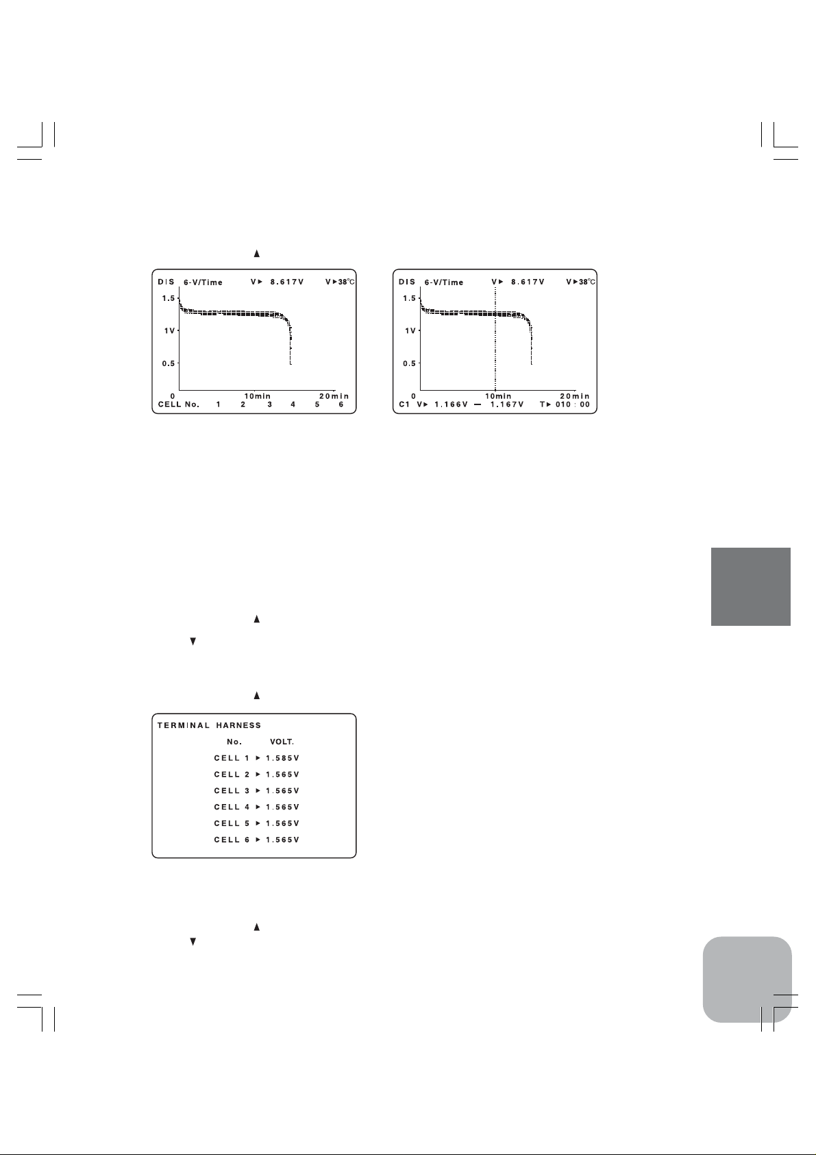
[GRAPH Screen Page 4 (DIS 6-V/Time)]
Pushing "Graph" or " " key in the "GRAPH Screen P age3" will sho w the "GRAPH Screen Page4".
This graph shows the relationship between the discharging time and cell voltage. (Connect Terminal
Harness to the batteries. This is not applicable to a battery of 7 cells or more.) Although no graphs will
be shown during charging, the graph of the previous charging graph will be shown after charging is
completed in cycle mode.
*The messages on the top of the screen are (from left to right):
Graph type and discharging current appears alternatively. (while discharging)
V: output voltage
B.T: temperature of the battery
CELL numbers (1-6) are shown at the bottom on the screen.
<How to operate>
See page 36 for the operating instructions.
Pushing "Graph" or " " key in the "GRAPH Screen P age4" will sho w the "GRAPH Screen Page5".
Pushing " " will show "GRAPH Screen Page3".
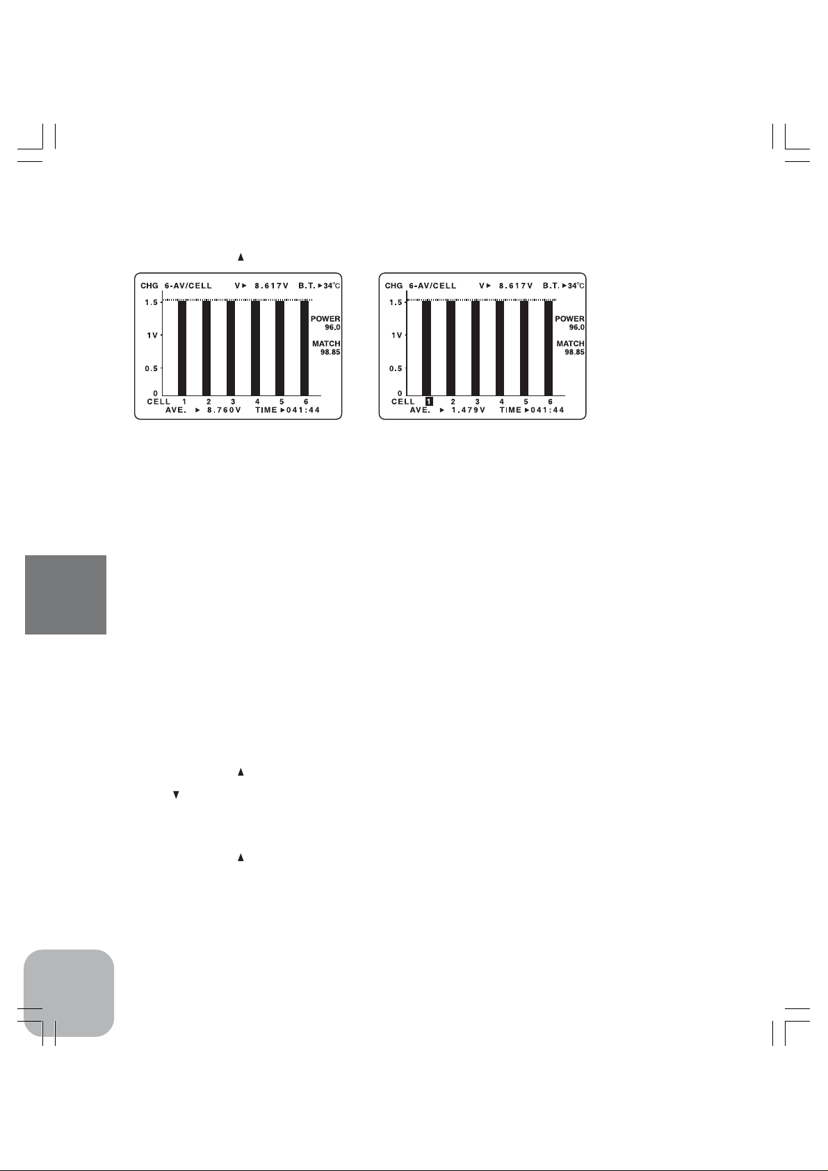
[GRAPH Screen Page 5 (TERMINAL HARNESS)]
Pushing "Graph" or " " key in the "GRAPH Screen P age4" will sho w the "GRAPH Screen Page5".
The voltages of each cell are shown on the screen. (Connect Terminal Harness to the batteries. Not
applicable to a battery of 7 cells or more)
<How to operate>
Pushing "Graph" or " " key in the "GRAPH Screen P age5" will sho w the "GRAPH Screen Page6".
Pushing " " will show "GRAPH Screen Page4".
CDR-5000 Functions
37
Page 37
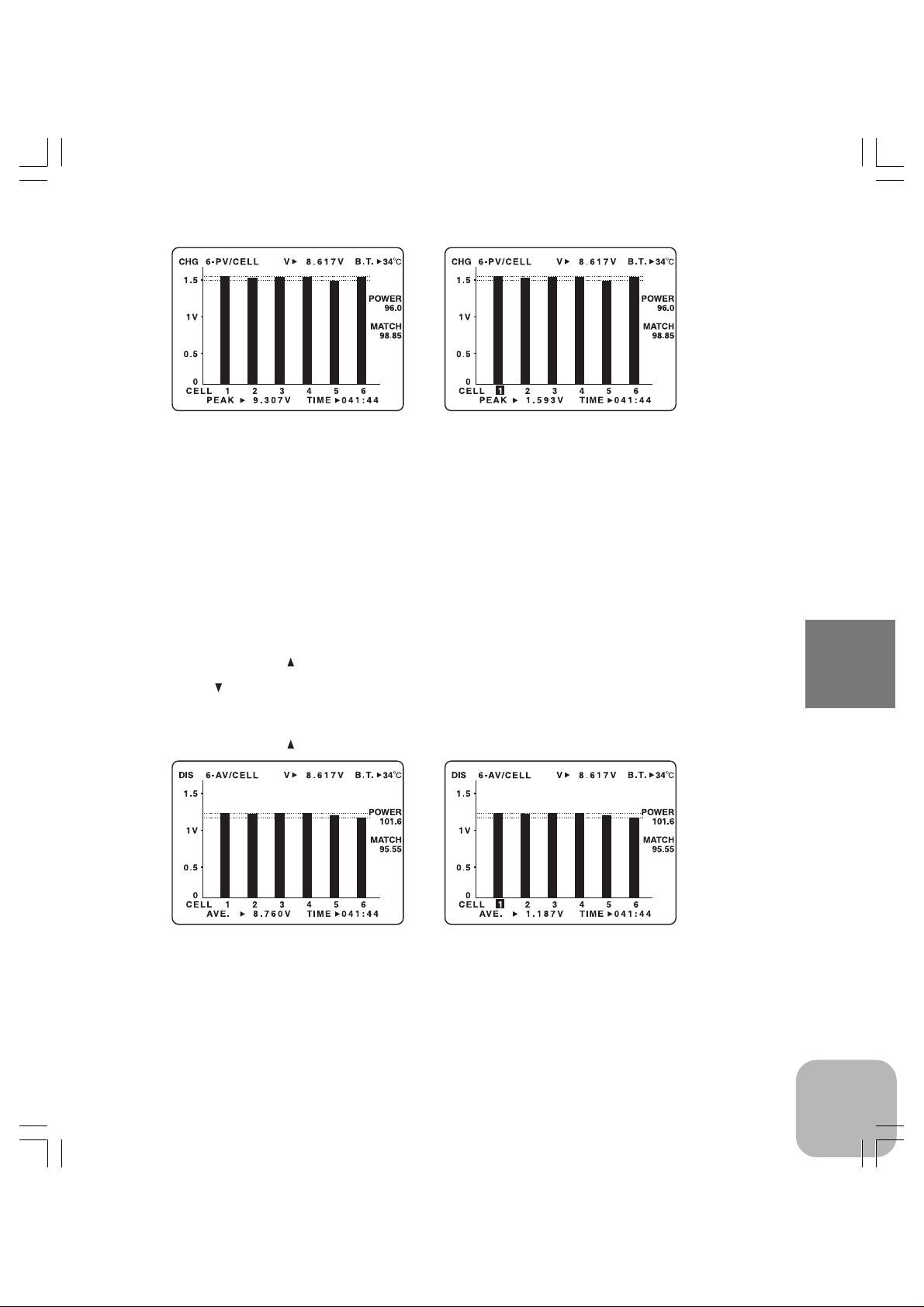
[GRAPH Screen Page 6 (CHG 6-AV/CELL)]
Pushing "Graph" or " " key in the "GRAPH Screen P age5" will sho w the "GRAPH Screen P age6".
This bar graph shows the average voltages of each cell in charging mode. (Connect Terminal Harness to
the batteries. Not applicable to a battery of 7 cells or more.) Although no graphs will be shown during
discharging ("no data" will be shown), the graph of the previous charging graph will be shown after
charging is completed in cycle mode.
*The messages on the top of the screen are (from left to right):
Graph type and charging current appears alternatively. (while charging)
V: output voltage
B.T: temperature of the battery
CELL numbers (1-6) are shown at the second line from the bottom on the screen.
At the bottom:
AVE: average charging voltage for all cells.
TIME: charging time
At the right on the screen:
POWER: power level
CDR-5000 Functions
MATCH: matched level
<How to operate>
In order to check the data of each cell, select the cell number by pushing "Enter" key. The average charge voltage of each cell will be shown after cell number blinking at the bottom on the
screen. Pushing "Enter" key each time shows cell number sequentially from "C1", "C2", "C3",
"C4", "C5", "C6". Pushing "Enter" key after "C6" shows the average charging voltage for all
cells.
Pushing "Graph" or " " key in the "GRAPH Screen P age6" will sho w the "GRAPH Screen P age7".
Pushing " " will show "GRAPH Screen Page5".
[GRAPH Screen Page 7 (CHG 6-PV/CELL)]
Pushing "Graph" or " " key in the "GRAPH Screen P age6" will sho w the "GRAPH Screen P age7".
This bar graph shows the peak voltages of each cell in charging mode. (Connect Terminal Harness to
the batteries. Not applicable to a battery of 7 cells or more.) Although no graphs will be shown during
discharging ("no data" will be shown), the graph of the previous charging graph will be shown after
charging is completed in cycle mode.
*The messages on the top of the screen are (from left to right):
Graph type and charging current appears alternatively. (while charging)
38
Page 38
V: output voltage
B,T: temperature of the battery
CELL numbers (1-6) are shown at the second line from the bottom on the screen.
At the bottom:
PEAK: peak charging voltage for all cells.
TIME: charging time
At the right on the screen:
POWER: power level
MATCH: matched level
<How to operate>
In order to check the data of each cell, select the cell number by pushing "Enter" key. Pushing
"Enter" key each time shows cell number sequentially from "C1", "C2", "C3", "C4", "C5", "C6".
Pushing "Enter" key after "C6" shows the peak charging voltage for all cells.
Pushing "Graph" or " " key in the "GRAPH Screen P age7" will sho w the "GRAPH Screen Page8".
Pushing " " will show "GRAPH Screen Page6".
[GRAPH Screen Page 8 (DIS 6-AV/CELL)]
Pushing "Graph" or " " key in the "GRAPH Screen P age7" will sho w the "GRAPH Screen Page8".
This bar graph shows the average voltages of each cell in discharging mode. (Not applicable to a battery
of 7 cells or more.) Although no graphs will be shown during charging ("no data" will be shown), the
graph of the previous discharging graph will be shown after discharging is completed in cycle mode.
*The messages on the top of the screen are (from left to right):
Graph type and discharging current appears alternatively. (while discharging)
V: output voltage
B,T: temperature of the battery
CELL numbers (1-6) are shown at the second line from the bottom on the screen.
CDR-5000 Functions
39
Page 39

At the bottom:
AVE : average discharging voltage for all cells.
TIME : discharging time
At the right on the screen:
POWER: Power level
MATCH: matched level
<How to operate>
In order to check the data of each cell, select the cell number by pushing "ENTER" k ey . Pushing
"ENTER" key gives the data of "AVE" after the cell number blinking at the bottom on the screen.
Pushing "ENTER" key each time shows cell number sequentially from "C1", "C2", "C3", "C4",
"C5", "C6". Pushing "ENTER" k e y after "C6" shows the a v er age discharging v oltage f or all cells .
Pushing "GRAPH" or " " key in the "GRAPH Screen Page8" will show the "GRAPH Screen
Page9". Pushing " " will show "GRAPH Screen Page7".
[GRAPH Screen Page 9(ENVIRONMENT INFORMATION ºC-%/TIME)]
Pushing "GRAPH" or " " key in the "GRAPH Screen Page8" will show the "GRAPH Screen
Page9".
CDR-5000 Functions
This bar graph shows temperature and humidity measured by Thermo Sensor built-in CDR-5000. Graph
type is shown on the screen.
*At the bottom:
OUTSIDE TEMP : temperature measured by the Thermo Sensor equipped with DR-5000
HUMID : humidity
<How to operate>
A cursor line vertical to the time axis will appear by pushing " " key.
The cursor line can be moved left and right by pushing " " and " " keys.
*The messages at the bottom of the screen will change when the cursor line appears.
At the bottom,
Temperature and Humidity
O.H : humidity
Before : the time where the cursor line is crossing the time axis
Pushing " " and " " keys simultaneously will erase the cursor and move back to the screen of
"OUTSIDE TEMP" and "HUMID".
Pushing "GRAPH" or " " key in the "GRAPH Screen Page9" will show the "GRAPH Screen
Page1". Pushing " " will show "GRAPH Screen Page8".
40
Page 40

Warning Screen
Please check once again !!
•Warning Message
"RELAY DAMAGE SERVICE 01!"
Relays used in CDR-5000 are out of order due to some reasons. Please contact the service department
of Futaba for repair.
This warning may appear if the Terminal Harness and a battery are connected to the DX terminal in
wrong way while you are using a power source of low current capacity. In that case, disconnect the
battery and reboot the CDR-5000. If this warning does not appear after this procedure, the relays are in
normal condition. It is recommended to use a power source that has high current capacity for charging.
And make sure the polarity before using CDR-5000.
"SHORT or REVERSE!"
This warning indicates an electrical shortage at output terminals of DX or TX&RX, a wrong polarity
connection of a battery or over-discharge. Check the conditions of terminals and the battery condition.
"DON'T TOUCH! BATTERY IS OVER HEATED!"
This warning appears when the temperature of the Thermo Stand (option) exceeds 75 degrees Celsius.
Be careful since the battery is very hot. The warning will be cleared as the temperature declines.
Pushing "Data" key can clear this warning.
"INPUT POWER SUPPLY VOLTAGE IS TOO LOW!"
This warning appears when the output voltage of a power source for charging drops.
Please check the output voltage of the power source.
"THERMO STAND DISCONNECTED or TEMPERATURE OVER RANGE!"
This warning appears when the Thermo Stand (option) is disconnected from the CDR-5000 and when
the temperature measured by it exceeds the specified temperature.
To clear the warning, push "Data" key or plug the Thermo Stand into the CDR-5000.
"CHARGE AMPERE IS TOO HIGH!"
This message appears when a charging current is set at between 5A and 12A for "SET CHARGE" at
DX in the "SET-UP" screen. Please confirm if there is no problem with the value before moving on to
next procedure. This message will appear no more than two times.
*If the warning is set to "OFF" in the Initial-setting, this warning will not be displayed.
CDR-5000 Functions
41
Page 41

"DISCHARGE AMPERE IS TOO HIGH!"
This message appears when a discharging current is set at between 10A and 40A for "SET DISCHARGE" at DX in the "SET-UP" screen. Please confirm if there is no problem with the value before
moving on to next procedure. This message will appear no more than two times.
*If the warning is set to "OFF" in the Initial-setting, this warning will not be displayed.
"CUT-OFF DELTA VOLTAGE IS TOO HIGH!"
This message appears when a Delta Peak Detection Voltage is set at between 20mV/cell and 50mV/cell
for "C CUT-OFF DELTA VOLT" at DX in the "SET-UP" screen. Please confirm if there is no problem
with the value before moving on to next procedure. This message will appear no more than two times.
*If the warning is set to "OFF" in the Initial-setting, this warning will not be displayed.
"CUT-OFF TEMPERATURE IS TOO HIGH!"
This message appears when a battery temperature to stop charging is set at between 50 and 75 degrees
Celsius for "C CUT-OFF TEMPERATURE" at DX in the "SET-UP" screen. Please confirm if there is
no problem with the value before moving on to next procedure. This message will appear no more than
two times.
*If the warning is set to "OFF" in the Initial-setting, this warning will not be displayed.
"CUT-OFF MAX. VOLT IS TOO HIGH!"
This message appears when the maximum battery voltage is set at over 13V for "C CUT-OFF MAX
VOLT" at DX in the "SET-UP" screen. Please confirm if there is no problem with the value before
moving on to next procedure. This message will appear no more than two times.
*If the warning is set to "OFF" in the Initial-setting, this warning will not be displayed.
"CUT-OFF CAPACITY IS TOO HIGH!"
This message appears when a charging capacity is set at over 4000mAh for "C CUT-OFF CAPACITY"
CDR-5000 Functions
at DX in the "SET-UP" screen. Please confirm if there is no problem with the value before moving on to
next procedure. This message will appear no more than two times.
*If the warning is set to "OFF" in the Initial-setting, this warning will not be displayed.
"CHECK YOUR CEELS NUMBER!" or "TOO MANY CELLS!"
This message appears when the number of battery cells is changed for "CELL NUMBER" at DX in the
"SET-UP" screen. Please confirm if there is no problem with the value before moving on to next
procedure. This message will appear no more than two times.
*If the warning is set to "OFF" in the Initial-setting, this warning will not be displayed.
42
Page 42

Specifications
Reference
*Specifications and ratings are subject to change without prior notice.
•Batteries
NiCd / NIMH batteries
•Input voltage
DC 12 - 16V (The guaranteed operating range is from
11V to 16V.)
•Charging current
DX port:
0.08 < Battery Voltage ≤ 18V: 0.1 -12A (0.01A step)
18 < Battery Voltage ≤ 27V: 0.1 - 8A (0.01A step)
27 < Battery Voltage ≤ 36V: 0.1 - 6A (0.01A step)
36 < Battery Voltage ≤ 43V: 0.1 - 5A (0.01A step)
43 < Battery Voltage ≤ 54V: 0.1 - 4A (0.01A step)
54 < Battery Voltage ≤ 62V: 0.1 - 3A (0.01A step)
TX&RX port:
0.05 - 2A (0.01A step)
•Charge-cut methods
DX port:
Detection by Delta Peak (Zero Delta, 3 - 50mV/cell)
Detection by battery temperature (25 - 75 degrees in
Celsius)
Detection by the maximum voltage (0.1 - 62V)
Detection by capacity (50 - 9999mAh)
•Discharging current
DX port:
0.1< Battery Voltage ≤ 2.4V: 0.1 - 40A (0.01A step)
2.4< Battery Voltage ≤ 7.5V: 0.1 - 40A (0.01A step)
7.5< Battery Voltage ≤ 8.5V: 0.1 - 35A (0.01A step)
8.5< Battery Voltage ≤ 10V: 0.1 - 30A (0.01A step)
10 < Battery Voltage ≤ 12V: 0.1 - 25A (0.01A step)
12 < Battery Voltage ≤ 15V: 0.1 - 20A (0.01A step)
15 < Battery Voltage ≤ 20V: 0.1 - 15A (0.01A step)
20 < Battery Voltage ≤ 30V: 0.1 - 10A (0.01A step)
30 < Battery Voltage ≤ 40V: 0.1 - 7.5A (0.01A step)
40 < Battery Voltage ≤ 50V: 0.1 - 6A (0.01A step)
50 < Battery Voltage ≤ 60V: 0.1 - 5A (0.01A step)
60 < Battery Voltage ≤ 62V: 0.1 - 4A (0.01A step)
TX&RX port:
below 10V: 0.1 - 5A (0.01A step)
above 10V: 0.1 - 3A (0.01A step)
•Discharge-cut methods
Detection by voltage: 0.8V/cell, 0.85V/cell, 0.9V/cell
Detection by time: 10 - 59940 seconds (999 minutes)
•Measurable temperature range
5 - 99 degrees Celsius
•Measurable humidity range
20 - 95%
•Expansion terminals
Thermo Stand port (Thermo Stand is an option)
Terminal Harness port (Terminal Harness is included
in a set)
PC port (only for the factory)
Printer port (only for factory)
•Screens
192 x 128 dot graphic LCD with backlight
•LEDs
Red : charging at DX or TX&RX
Blue: discharging at DX or TX&RX
•Power consumption
Less than 8W at 12V (at idle)
•Operating temperature
5 - 40 degrees Celsius
•Storage temperature
-20 - 60 degrees Celsius
•Size
170 x 170 x 83mm (excluding cords and terminals)
•Weight
1200g
•Protection circuits
Protection circuits against overload, reverse connection and overheat
Reference
43
Page 43
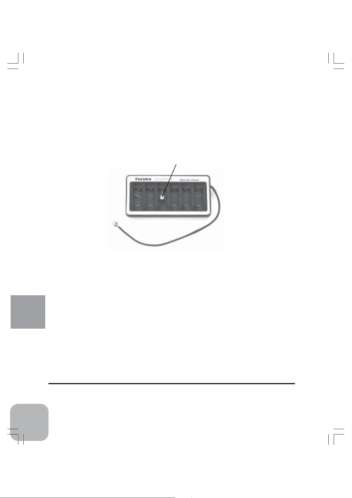
Option Parts
Thermo Stand
This is designed for measuring the temperature of a battery of 6 cells or less for motors that are being
charged or discharged by CDR-5000.
•Temperature Sensor
*This is for measuring temperature for monitoring the characteristics
of a battery under charging or discharging and for stopping charging
or discharging by the preset temperature.
*Trimmer is located on the back of the Thermo Stand.
•Connector
*This connector is used for connecting
the Thermo Stand to CDR-5000.
Reference
44
FUTABA CORPORATION
Makuhari Techno Garden Bldg., B6F 1-3 Nakase, Mihama-ku, Chiba 261-8555, Japan
Phone: (043) 296-5119 Facsimile: (043) 296-5124
©FUTABA CORPORATION 2004, 01
 Loading...