

Page 1
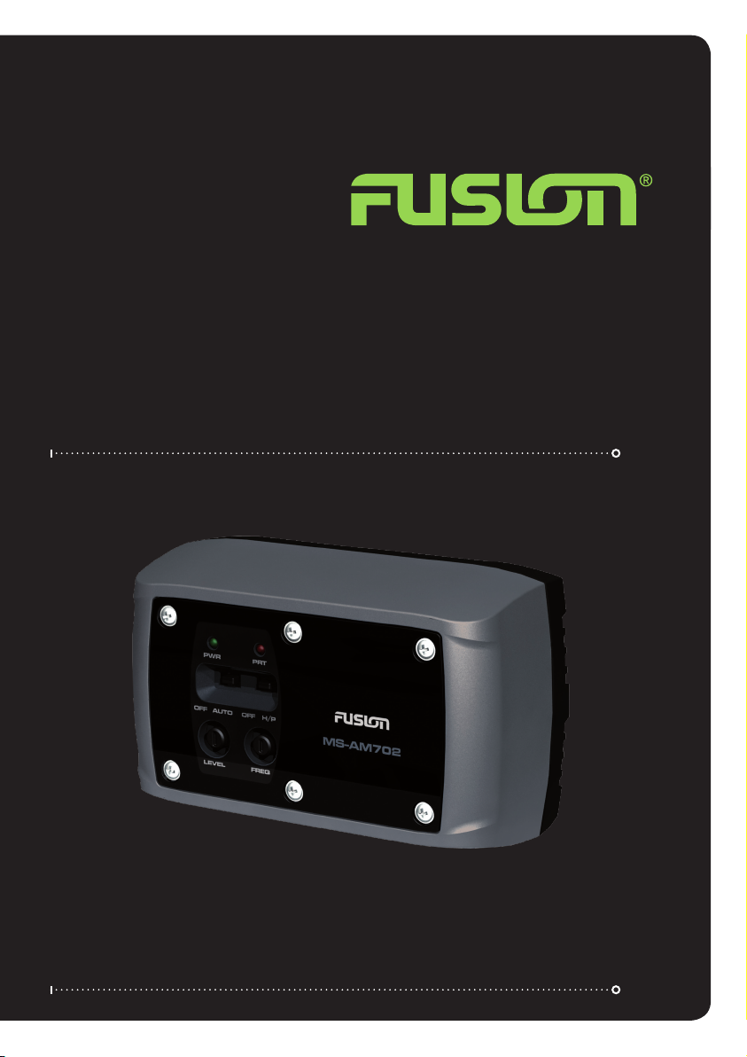
User / Installation Manual
Marine Zone Amplifier
MS-AM702
Page 2
Contents
Installation
Installation . . . . . . . . . . . . . . . . . . . . . . . . . . . . Pg 3
Installation Warning . . . . . . . . . . . . . . . . . . . . Pg 3
Mounting . . . . . . . . . . . . . . . . . . . . . . . . . . . . . Pg 3
Wiring . . . . . . . . . . . . . . . . . . . . . . . . . . . . . . . . Pg 4
Control Descriptions.................... Pg 6
Specifications.......................... Pg 7
RECORD YOUR PRODUCT DETAILS HERE:
MODEL NUMBER DATE OF PURCHASE
AFFIX RECEIPT HERE
Before any wiring and installation is performed, FUSION recommends you rst plan the complete installation. Look
at wiring routing, amplier location and mounting options. Please re-check the installation at completion.
Appropriate mounting is very important for prolonged life expectancy of any amplier.
Select a location that allows enough space for sucient airow to be maintained. Excessive heat will shorten the
ampliers life. To maximize heat dissipation, be sure to leave at least 2.5 inches of clearance around the amplier.
Installation Warning
1: Ensure the marine vessels +12V lead is removed from the battery before any equipment is connected
2: Investigate the marine vessels fuel tanks and electrical wiring locations before you begin installation
3: Ensure all wiring is protected to avoid damage
When wiring the FUSION amplier, ensure that the wires are away from sharp objects and that rubber grommets
and insulated bungs are used when routing the wiring. Ensure that when connecting the wires to the speakers
and audio system, the terminals and connections are protected from shorting to each other.
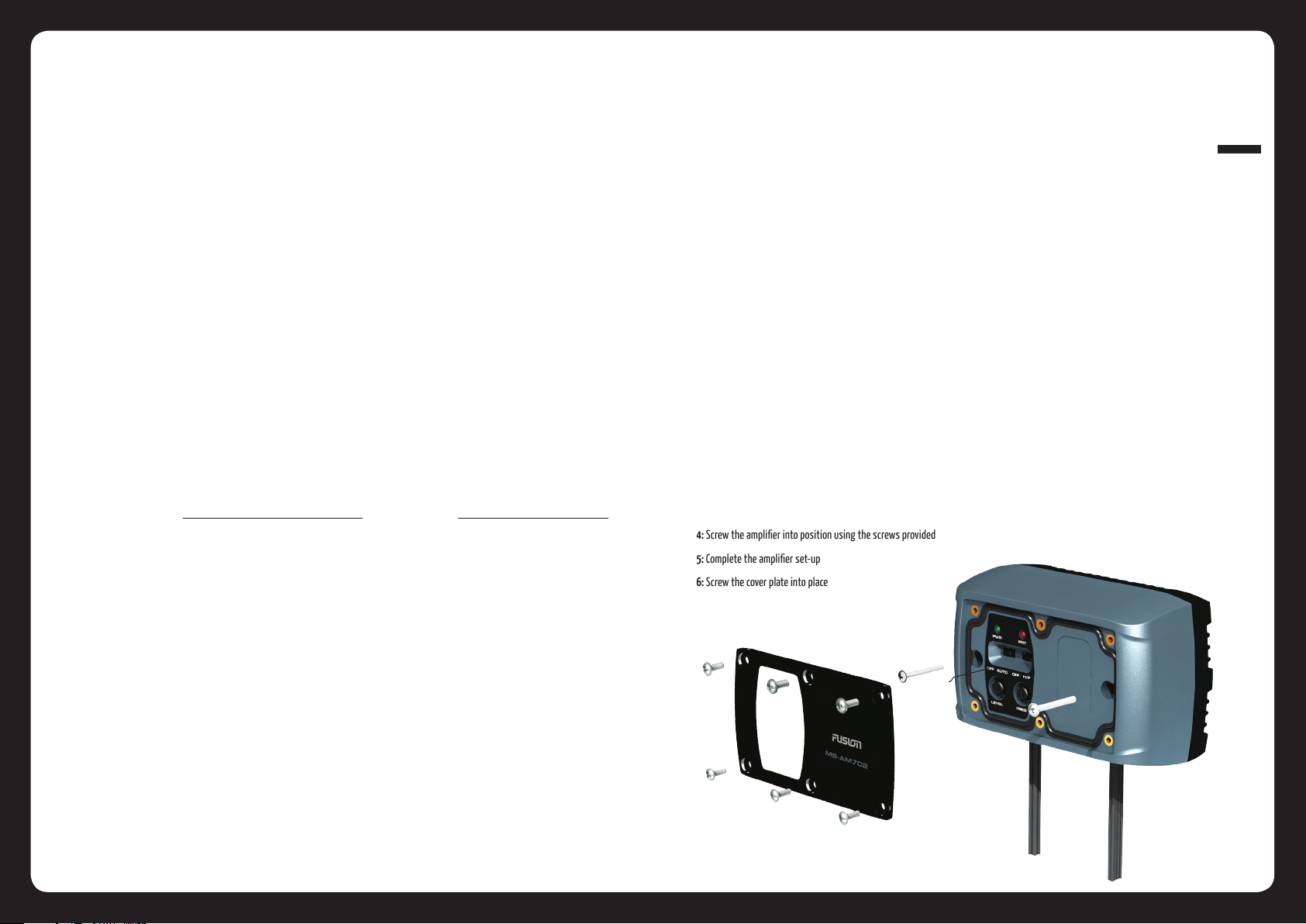
Mounting
1: Remove the 6 cover plate screws
2: Align the amplier into the position required and mark the mounting holes
3: Pre Drill the mounting holes
4: Screw the amplier into position using the screws provided
5: Complete the amplier set-up
6: Screw the cover plate into place
003
INSTALLATION
2010 Version 1.0
Page 3
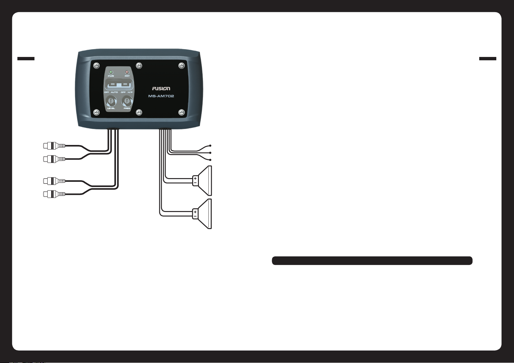
WIRING
WIRING
004
AUX IN
AUX OUT
NOTE: Each Channel 2 Ohms Stable
ie. 2 x 4 Ohm Speakers can be run in parallel o each channel
Channels cannot be bridged
GREY
BLACK
WHITE
WHITE/BLACK
GREY
GREY/BLACK
YELLOW - Battery 12V DC (B+)
BLUE - Remote Turn On
BLACK - Negative Ground (B-)
LEFT SPEAKER
RIGHT SPEAKER
Power
FUSION ampliers should be wired directly to the vessels battery using the appropriate sized cable. Start at the
vessels battery and run the power cable through to the amplier. FUSION recommends the use of grommets when
passing the power cable through any metal / bre glass walls, and to avoid sharp corners that may easily cut
through the insulation on the cable.
The use of an inline fuse at the battery position is essential. This will prevent the risk of a potential re caused by
a short circuit in your power cable. Connect the fuse holder as close to the battery positive terminal as possible.
You may now connect the cable to the battery, but remember to leave the fuse out or circuit breaker o until all
other cable connections are made.
Avoid running the power cable over engine components.
Remote Turn On
This wire must be connected to a switched +12V source, if the “Auto On/O ” switch is located in the O position.
Typically, remote turn-on leads are provided at the headunit which will turn the amplier on/o in correspondence
with the source. If the head unit does not have a remote turn-on lead then a switched +12V supply can be used,
like the ACC +12V or alternatively turn the “Auto On/O ” switch to the ON position.
Auto ON/O
The Auto On/O switch allows an easy solution if a REMOTE wire cannot be used. When “ON” is selected the
amplier will turn on when an audio signal is detected from the source, when no signal is present the amplier will
automatically shut down after 1 minute. When O position is selected a Remote Switched +12V supply must be
used as described above.
Speaker Wiring
Choose the correct speaker wire for your application. Most applications will require a minimum of 16 gauge. Route
the speaker wire using the same precautions you did when you ran the power cables. Terminate these wires at
the speaker end using insulated speaker terminals (not supplied) or by soldering the connection. Make sure the
speaker connections are positive to positive and negative to negative. Ensure you have maintained the correct
polarity and balance.
Speaker Load
The Marine Zone amplier requires a minimum impedance of 2 Ohms STEREO (per channel) to operate trouble free.
005
WIRING
Ensure before any connection is made to the amplier or source unit, that you turn the audio system o. Failure to
do so could result in either the stock system or your new FUSION product being damaged.
FUSION will not warranty damaged ampliers due to incorrect installation.
Ground
When grounding your FUSION Amplier locate a metal area close to the amplier that is a good source of ground.
Use either a wire brush or sandpaper to eliminate unwanted paint, rust and corrosion. This will allow a better
contact for your ground. Use the same gauge cable for the ground as you did for the power. Secure the ground
cable using a solid connection. Spread silicon over the screw and bare metal to prevent corrosion.
WARNING: The Amplier CANNOT operate MONO!!!!! (bridged) This will result in damage to the amplier
Low Level Inputs
Choose the correct length and style of RCA interconnects for your needs.
Avoid running your RCA’s near large wire looms and electric fans if possible. Be sure to check for correct balance.
(Red is right channel and Black or White is left channel).
Low Level Outputs
Use these RCA output connectors to connect to a secondary amplier.
Page 4

CONTROL DESCRIPTIONS
SPECIFICATIONS
WIRING
006
1
3
6
1: PWR LED (Blue)
When illuminated the amplier has been correctly powered up.
2: PRT LED (Red)
When illuminated the amplier is in protection mode.
3: AUTO ON/OFF
Switch for desired operation. See notes Auto ON/O operation
4: High Pass (H/P) Switch
Set the appropriate mode of operation. The two positions available are OFF (full range) and H/P. See point 5 below.
5: FREQ Control
Set the crossover switch 4 to H/P and turn this control to 60Hz or above (range 60Hz – 600Hz) when using speakers smaller
than 6 x 9”. This feature is designed to lter out all low bass frequencies. Note: Failure to do so could result in speaker damage.
6: LEVEL Control
The level control on the amplier allows you to match the input level of the amplier to the output level of your head unit. Matching the input can be accomplished in three simple steps:
1: Turn the LEVEL control on the amplier to minimum.
2: Adjust the Headunit to 3/4 maximum volume ensuring that the BASS and TREBLE are set to zero.
3: Adjust the LEVEL control until the desired volume is achieved without audible distortion. Remember, the level control is not a
volume control. Ignoring the three steps above may damage your speakers and/or amplier.
2
4
5
Operating Range +10-16Volts DC / Negative Ground
20 Watts RMS at 4 Ohms per channel @1%THD+N
33 Watts RMS at 2 Ohms per channel @1%THD+N
S/N Ratio @ 1kHz / 1W Reference -- 84dB
High Pass x-over - 60Hz – 600Hz
Maximum Operating Current - 8 AMPS
THD 10% @ 1kHz / 4 Ohm Load per channel
For further product and installation information please visit www.fusionelectronics.com
Para obtener más información sobre los productos o su instalación, visite
www.fusionelectronics.com
Weitere Informationen zum Produkt und zur Installation nden Sie auf folgender
Website: www.fusionelectronics.com
Ga naar www.fusionelectronics.com voor meer product- en montage-informatie
Pour plus de renseignements sur les produits et l’installation, veuillez consulter
www.fusionelectronics.com
Per ulteriori informazioni su prodotto e installazione, potete visitare
www.fusionelectronics.com
За дополнительной информацией о продукции и установке обращайтесь на
www.fusionelectronics.com
PUBLISHED BY FUSION ELECTRONICS LIMITED:
All rights reserved. Specications and design are subject to change
© Copyright 2008 by FUSION Electronics Limited.
without notice.
YOU CAN HELP PROTECT THE ENVIRONMENT!
Please remember to respect the local regulations:
Hand in the non-working electrical equipment
to an appropriate waste disposal center.
007
SPECIFICATIONS
Page 5

Specications and design are subject to change without notice.
 Loading...