

Page 1
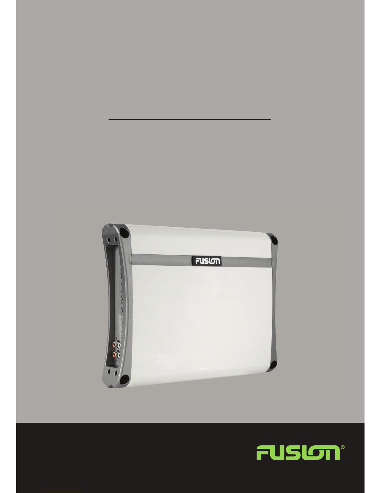
MS-AM402
MARINE AMPLIFIER
User/Installation Manual
FUSIONENTERTAINMENT.COM
Page 2

Contents
Feature Overview ....................................Pg 3
Control Descriptions . . . . . . . . . . . . . . . . . . . . . . . . . . . . . . . . .Pg 4
Installation . . . . . . . . . . . . . . . . . . . . . . . . . . . . . . . . . . . . . . . . .Pg 6
Connections . . . . . . . . . . . . . . . . . . . . . . . . . . . . . . . . . . . . . . . .Pg 6
Inputs and Gain Setup . . . . . . . . . . . . . . . . . . . . . . . . . . . . . . . .Pg 8
Single Channel Installation .............................Pg 8
Two Channel Installation / Power Cable Calculator...........Pg 9
Trouble Shooting / Specifications .......................Pg 10
RECORD YOUR PRODUCT DETAILS HERE:
MODEL NUMBER DATE OF PURCHASE AFFIX RECEIPT HERE
2010 Version 1.0
Page 3

Feature Overview
• 2 Ohm Stable MOSFET Amplifier Design
• Variable Bass Boost 0 - + 18dB
• Variable LP and HP Electronics X-OVER @ 18dB/octave
• 4 Gauge Power and Ground Connections
• Nickel Plated Audio Input and Output RCA Connections
• Nickel Plated RCA Output for multi-amp Installations
2-OHM STABLE STEREO
Provides the option of connecting an extra pair of speakers in parallel, 2
per channel at 2-Ohms (A total of 8 speakers).
MARINE GRADE CONNECTIONS
Nickel plated RCA connectors and stainless components improve signal
flow for optimum output
003
FEATURE OVERVIEW
CLASS-AB DESIGN
The 500 Watt 2-Ohm stable (per channel) design ensures clean and
powerful amplification of the input signal, enough to rock the boat.
CONFORMAL COATED CIRCUITRY
Provides added protection from salt air and moisture to ensure maximum
product life.
MARINE GRADE CHASSIS
Stainless steel end and bottom plates provide a stunning finish coupled
with environmental protection.
RCA LINE OUT
A pass through RCA output enables linking of multiple amplifiers for
enhanced system performance
Page 4
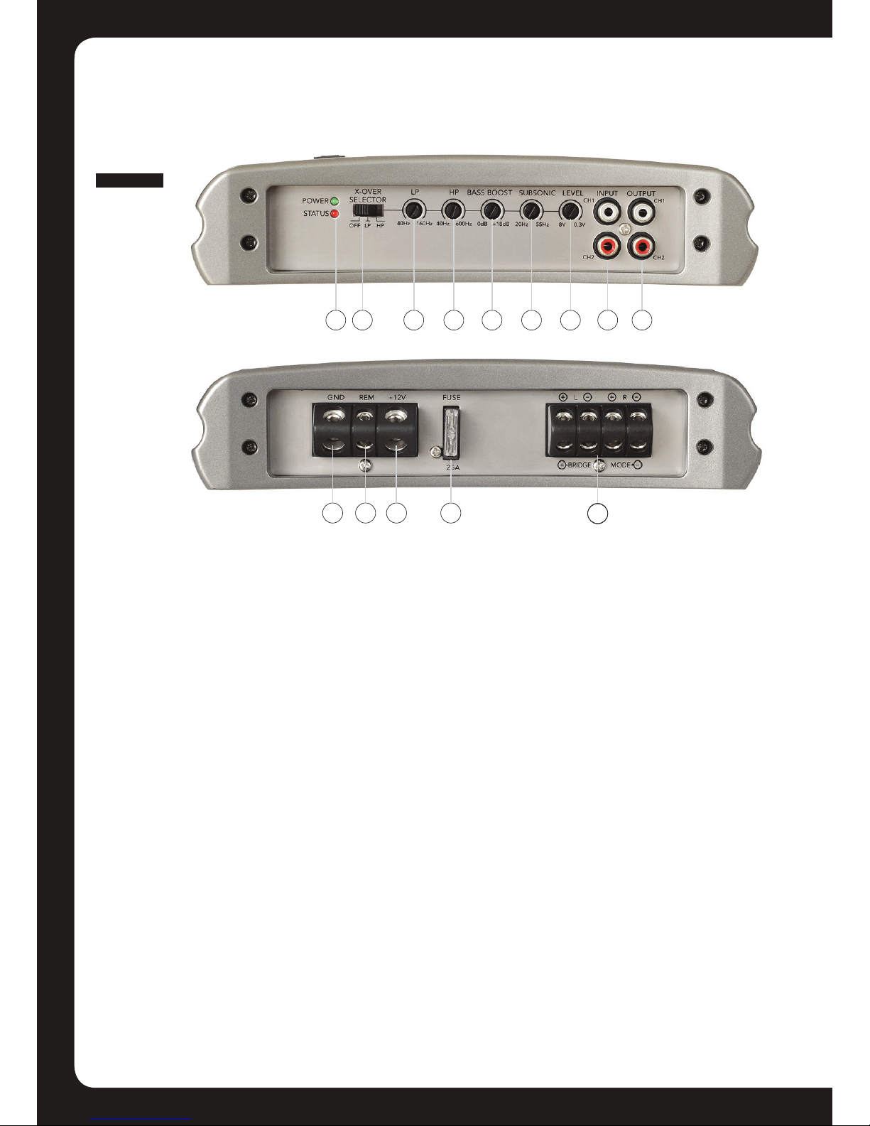
Control Descriptions
CONTROLS
004
2
1
10 11
12
4
3
13
14
9
8765
1 Power And Status LEDs:
This shows if the amplifier has been correctly powered up and if any faults are present.
2 Crossover Selector:
Set the appropriate mode of operation. The 3 positions available are OFF, LP and
HP.
3 Low Pass:
Set the crossover switch 2 to LP when a subwoofer is connected. Ensure the crossover frequency is set at 100Hz or below, this feature is designed to filter all mid to
high frequencies that only FULL RANGE speakers should produce. NOTE: Failure to
do so could result in speaker damage.
4 High Pass:
Set the crossover switch 2 to HP and turn this control to 65Hz or above when using
speakers smaller than 6”, this feature is designed to filter all low bass frequencies
that only SUBWOOFERS should produce. NOTE: Failure to do so could result in
speaker damage.
5 Bass Boost:
This is a variable control to increase the bass boost at 45Hz from 0 -+18dB of gain,
adjust to suit.
Page 5

6 Subsonic Filter:
This is a variable control filters out all Sub Bass Frequencies below the set point at
18dB/octave.
7 Level:
This allows level adjustment of the input signal. Use this control to correctly match
the head unit to the amplifier. To set this control correctly, turn the amplifier level
to MIN and the head unit to 3/4 volume, with the BASS and TREBLE on zero , then
slowly turn up this amplifier level control towards the MAX end of the control.
NOTE: If the sound becomes distorted, turn this control down.
8 RCA Input:
Connect these RCA connectors to the LOW LEVEL output connection from the head
unit.
9 RCA Output:
Use these RCA Output connectors to connect to a secondary amplifier. This output
is a PASS-THRU connection derived from the RCA input connector so the signal
level and frequency response are the same as the original input signal.
10 Ground Connection:
005
CONTROLS
Connect directly to a suitable ground point via a 4 gauge power cable. NOTE: This
is to be the first wire to connect. Damage could result if this is not done.
11 Remote Connection:
This input is for turning the amplifier on and off. This requires a switched positive
(+12V) to power ‘ON’ the amplifier, this can be found on the rear of the head unit in
the form of an electric antenna output, or a remote on output. If not available you
can wire to a switched +12V supply.
12 Power +12V Connection:
This must be connected to the battery positive (+) terminal via a 4 guage power
cable and with an inline fuse or circuit breaker at the battery end. NOTE: This is to
be the last wire to connect up during installation as damage could result.
13 Fuse:
Please ensure the correct type of fuse is fitted, as specified in this manual. PLEASE
NOTE: the MS-AM402 has 1x 25A fuse.
14 Speaker Output:
See channel installation diagrams in this manual for correct speaker connection.
Page 6

Installation
Mounting
INSTALLATION
006
Appropriate mounting is very important for the prolonged life expectancy of any
amplifier. Select a location that allows enough space so sufficient airflow is maintainable
and a location that provides protection from moisture. Keep in mind that an amplifier
should never be mounted upside down. Upside down mounting will compromise heat
dissipation through the heatsink and could engage the thermal protection circuit.
Excessive heat will shorten your amplifiers life. To maximise heat dissipation, be sure to
leave at least 2.5” of clearance around the amplifier. If space is of the essense and the
amplifier must be mounted in an enclosed or restricted area, a small 3 inch fan should
be used in correspondence with a duct so the heat can flow past the Heatsink.
To avoid scratching your new FUSION amplifier, pre-drill the mounting holes with either
a 3mm or 9/64” diameter drill bit and use the screws supplied in the accessory kit. Be
sure to investigate your mounting area thoroughly to avoid electrical wires, vacuum lines
or fuel lines.
Installation Options
The quality of installation will affect the performance and reliability of your FUSION
amplifier. For maximum performance we recommend you have your new FUSION
amplifier installed by an authorised FUSION dealer. Our highly skilled dealers have vast
knowledge of our products and their installation techniques are necessary to unleash
the high performance capabilities of your amplifier.
If you decide to connect the amplifier yourself, it is important that you read this manual
carefully and throughout before starting. Once you have finished reading and you still
have questions regarding installation, we recommend your FUSION dealer.
Connection
FUSION amplifiers are designed to work within a 10 to 16 volt DC range. Before
any wires are connected, the vessel’s electrical system should be checked for correct
voltage supply with the help of a voltmeter. First, check the voltage at the battery the
voltmeter should read between 12 and 13.8 Volts. If your vessel’s electrical system is
not up to these specification, we recommend having it checked by an auto electrician
before any further installation. Once the vessel is checked, make certain the correct
cable size is used. We recommend using the following cables calculator diagram on
page 9 to calculate the correct power cable for your application.
Power
FUSION amplifiers should be wired directly to the battery using the appropriate sized
cable. Start at the vessels battery and run the power cable through to the amplifier.
FUSION recommends the use of grommets when passing the power cable through any
metal wall to avoid sharp corners or sharp body parts that may easily cut through the
insulation on the cable.
Avoid running the power cable over engine components. The use of an inline fuse
or circuit breaker is a must, this will prevent the risk of a potential fire caused be a
short in your power cable. Connect the fuse holder or circuit breaker as close to the
Page 7

battery positive terminal as possible. Use a fuse or circuit breaker of equal value as that
found on the chassis of your FUSION amplifier. You may now connect the cable to the
battery, but remember to leave the fuse out or circuit breaker off until all other cable
connections are made.
Ground
When grounding your FUSION amplifier, use the same gauge cable for ground as
you did for the power. Secure the ground cable to the appropriate ground point, now
its time to connect the power and ground cables to the amplifier. Cut both cables to
length. Use a hex type screwdriver to loosen the +12V and the GND connections on the
amplifier. Terminate the ground first, and then the +12V and please make sure that you
terminate them into the correct terminals. Then tighten the screws down securely.
Speaker Load
Keep in mind FUSION ‘AM’ series amplifiers are high power amplifiers and not high
current amplifiers. In other words they require a minimum impedance of 2 ohms
STEREO and 4 ohms bridged MONO to operate trouble free. Too low of an impedance
could send your FUSION amplifier into protection mode and/or damage the amplifier.
Remote Turn-on
This terminal must be connected to a switched +12V source. Typically, remote
turn-on leads are provided at the head unit which will turn on and off the amplifier. If the
head unit does not have a remote turn-on lead, then a power antenna wire can be used.
If neither of these leads are present on the head unit then a switched +12V supply must
be used , like the ACC +12V.
007
CONNECTION
Run a minimum of 18 gauge wire from the amplifier location to the source of the
switched +12V lead. Connect the source remote output to the wire. Go back to the
amplifier and cut the wire to length. Loosen the screw terminal marked REM on the
amplifier using a hex type screwdriver. Slip the wire into the connector and tighten the
screw securely.
Page 8

FUS
Inputs & Gain Setup
Low Level Inputs
INSTALLATION
008
Be extra careful with your RCA interconnects. Hiss, engine noise, and fan noise can
easily be picked up through RCA cables if run incorrectly. Avoid running your RCAs near
large wire looms and electric fans if possible. Run your RCA cables on the opposite side
of the power cable. Be sure to check for correct balance (Red is right and black or white
is left)
Level Control
On the amplifier, is the LEVEL control, this control allows you to match the input level of
the amplifier to the output level of your head unit. Matching the input can be accomplished in three simple steps:
1. Turn the LEVEL control on the amplifier to minimum.
2. Turn up the head unit and adjust to 2/3 maximum volume ensuring that the BASS
and TREBLE are set to zero.
3. Adjust the LEVEL control until the desired volume is achieved without audible distortion.
Remember, the gain control is not a volume control. Ignoring the three steps above may
leave you with damaged speakers and/or a damaged amplifier.
Single Channel Installation
FUSE
E
Page 9

Power Cable Calculator
Total Amperage
0-20 14 12 12 10 10 8 8 8
20-35 12 10 8 8 6 6 6 4
35-50 10 8 8 6 4 4 4 4
50-65 8 8 6 4 4 4 4 2
65-85 6 6 4 4 2 2 2 0
85-105 6 6 4 2 2 2 2 0
105-125 4 4 4 2 0 0 0 0
125-150 2 2 2 0 0 0 0 0
The above chart shows cable gauges to be used, if no less than a 0.5 volt drop is acceptable. If aluminium wire or tinned wire is used, the gauges should be of
an even larger size to compensate. Cable gauge size calculation takes into account terminal connection resistance. 1 Metre = 3.28 Feet
0-4ft 4-7ft 7-10ft 10-13ft 13-16ft 16-19ft 19-22ft 22-28ft
Two Channel Installation
009
CONNECTION
FUSE
Page 10

Trouble Shooting
INSTALLATION
010
Problem Cause Solution
Power LED
not ‘ON
Status LED
‘ON’
Fuse at battery blown
or not installed
Improper connections
Fuse blown
Amplifier too hot
Speaker wires shorted
Internal malfunction
Replace with correct type and rated fuse.
Check that the ground wire, power wire and the remote
wires are connected to the correct terminal
Replace with correct type and rated fuse.
Move the amplifier into a more ventilated area
Check that there are no speaker wires shorted to any
other wire and also check if any wire is shorted to
ground
Disconnect all wires except ground, power and remote. Then turn the
amplifier ’ON’, if the protection light is still ’ON’ then return for service
Specifications
Signal to Noise >95dB
Separation >60dB
Input Sensitivity 300mV - 8V
LP Variable Crossover 40Hz - 160Hz @ 18dB/octave
HP Variable Crossover 40Hz - 600Hz @ 12dB/octave
Variable Bass Boost 0 - + 18dB @ 45Hz
Variable Subsonic Filter 20Hz - 55Hz @ 18dB/octave
Input Impedance 20k Ω
Damping factor >200
T.H.D 0.05%
Fuse Ratings 1 x 25A
Dimensions(mm) 229 (W) x 296(L) x 53vz(H)
12.6 Volt power output specification
50 Watts RMS x 2 @ 4Ω 1% THD+N
96 Watts RMS x 2 @ 2Ω 1% THD+N
160 Watts RMS x 1 @ 4Ω Bridged 1% THD+N
14.4 Volt power output specification
65 Watts RMS x 2 @ 4Ω 1% THD+N
100 Watts RMS x 2 @ 2Ω 1% THD+N
200 Watts RMS x 1 @ 4Ω Bridged 1% THD+N
Page 11

Page 12

FUSIONENTERTAINMENT.COM
Page 13

Page 14

LIMITED
1
YEAR
MARINE
CONSUMER
WARRANTY
Garmin New
from defects
•
The initial
purchase of the
•
The
or
•
The
www.fusionentertainment.com.
product.
•
During the
discretion). any defective
No
parts
these limited
•
Repaired
repair,
•
All
The consumer shall have
Zealand Ltd.,
in
material
limited
limited
warranty
transferable
limited
warranty
limited
charge
warranty
will
and cosmetic
warranty
product
whichever
claims
trading
and
warranty
product
extends only to the
to any subsequent purchaser/end user.
extends only to
warranty
be
made to the
parts
terms.
will
be
is longer.
must
as
FUSION
workmanship,
for
the
The limited
period,
product
warranted
be
no
or
consumer
should
be
accompanied
coverage or benefits under this Limited
Entertainment
according
FUSION
parts
for
product
original
consumers
FUSION
thereof
for
free of defects at the
the balance of the
with
to
consumer
who purchase the
warranty
or
its authorised service
with
either
parts
a copy of this
('FUSION')
the following terms
purchased extends to the
purchaser
is only valid
new and
or
labour
time
original
warranty
are applicable:
•
The product has been subject to:
unauthorised connections, unauthorised
misuse, neglect, abuse, accident , alteration,
customer
consumable
workmanship,
• FUSION
limited
• The product
•
The product was used
used
If
a problem develops during the limited warranty period, the consumer
1.
The
replacement processing.
FUSION dealer,
2.
The
be
responsible
3.
If
the product is
apply and the
THE
BENEFITS
ANY
OTHER
TO
THE
PURCHASER'S
THE
EXTENT
A
LOSS
• Some states in
exclusion may not apply to you. This
• FUSION
obligation
•
All
warranty
controls
parts
was not notified
warranty
serial
in
a
manner
consumer
consumer
or
such as fuses, and breakage
and
normal
period.
number
with
other
shall
return
or
return
shall
be
charged
for
expenses related to
returned
consumer
CONFERRED
RIGHTS
AND
REMEDIES
EXTENT PERMITTED
SOLE
AND
PERMITTED
OF
ANTICIPATED
neither
or
liability
information,
BENEFITS
America
assumes
beyond that which is expressly provided
other
by
than its intended use.
FUSION
freight
to
will
BY
BY
EXCLUSIVE
BY
LAW,
do
nor
product
abnormal
acts which are beyond the reasonable
wear
and
tear
the
consumer
or
the accessory date code has been removed, defaced
or
connected to
the product to any authorised
assumes no freight
from
for
any
FUSION
be
after
charged accordingly.
THIS LIMITED
UNDER
LAW,
ANY
REMEDY
FUSION
OR
PROFITS,
not
allow
warranty
authorises
features and specifications are subject to change
use,
abnormal
repair
including but not
improper
or
damage to antennae unless caused
of the product.
of the alleged defect
an
accessory not supplied
an
authorised
parts
or
removal
the expiration of the
dealer
labour
and
reinstallation
WARRANTY
ANY
APPLICABLE
IMPLIED
SHALL
the exclusion
any authorised service centre
WARRANTY
AND
IS
NOT
OUT
OF
or
gives you specific
conditions,
installation, acts of
FUSION
or
shipping
to the
charges not covered
APPLY
LEGISLATION
IN
LIEU
OF
BE
LIABLE
USE
OR
limitation
for
warranty
IS
warrants that this
and
conditions:
first
12
months beginning on the date of
[consumer) of the product and is not assignable
product
in
return
of
shipment
warranty
limited
or
responsibility
consumer
of the product.
TO
THE
EXCLUDED
ALL
FOR
INABILITY
of consequential damages,
legal
in
this
in
one of the countries (or areas) set
FUSION's
the
in repairing
card, and a copy of proof of purchase.
improper
malfunction
by
should
dealer
period,
EXTENT
OTHER
INCIDENTAL
rights
or
warranty.
intended country (or areal of sale of the
network
product
period
warranty
to use of unauthorised spare
God,
control
FUSION
will
to the
or
replacing the product.
and, therefore
or
for
if any
storage, unauthorised modifications,
spill
of foods
of
FUSION,
directly
of the product during the applicable
or
altered.
or
fit
for
take the following step-by-step procedure:
in authorised sales countries
for
returning
submitting
by
this limited
FUSION'S
THAT
THEY
THAT
CANNOT
AND
THE
FOREGOING
WARRANTIES,
OR
CONSEQUENTIAL
TO
USE
THE
PRODUCT.
which may vary
any person
or
without
FUSION
repair
consumer
ninety
the
warranty.
Marine product
or
replace (at
in
working
All
shall
not
be
covered
(90)
days
from
of
the following conditions
parts
or
liquids,
including deficiencies
by
use with
warranty
normal
ARE
BE
EXCLUDED.
maladjustment
defects in
goods to an authorised
service policies
NOT
materials
FUSION
for
claim.
The
consumer
SUPERCEDED
OTHERWISE,
WARRANTY
EXPRESS
OR
IMPLIED.
DAMAGES
so
the above
from
state
entity to assume
notice.
limitation
to
state.
for
is
free
forth
FUSION's
condition.
replaced
under
the date of
in repairs,
product,
repair
shall
shall
IS
THE
OR
and
it any
other
on
of
in
or
or
or
BY
TO
Page 15

LIMITED 1 YEAR
MARINE
CONSUMER
WARRANTY
Garmin
EMAIL:
THE FUSION PROMISE
This
addition to the Fusion
Law.
foreseeable
quality
Garmin
Speaker, Subwoofer,
workmanship,
• The
• The
•
• Repaired
•
This
The consumer causes the Product
becoming of unacceptable quality
quality
• Storage of
• Exposure to excessive
• Exposure to excessive
•
•
• Damage caused by
•
• Using the
• Any
• This
• Repair
•
• Fusion is not
Australia
australiarafusionentertainment.com
warrant
You
are
and
New
limited
limited
other
person
During
faulty
product
after
the date of repair,
All
warranty
with
a copy of
accessory
Warranty
or
of
Unauthorised
unauthorised
use of
Improper
breakage
Acts
of god [force
specified
other
Other exclusions;
warranty
expenses
product
Fusion
may apply.
• This is a
made
by
authorised
and
All
warranty
failure,
Limited,
is given in addition to
entitled
loss
or
the
failure
Zealand Ltd., trading as FUSION
in
accordance with the following
warranty
warranty
or
the
limited
or
or
replaced
claims
this
date code.
will
abnormal
product
modifications
use of
or
damage
product
by,
or
authorised
abnormal
extends to the
relating
to Fusion
work
conducted
warranty
manufacturers
Fusion and
dealers
information,
responsible
or
during
Unit
OF
QUALITY LIMITED 1 YEAR CONSUMER WARRANTY
Warranty
to a
damage.
does not
Amplifier
for
extends only to the
consumer
warranty
parts
at
product
whichever
must
warranty
not apply if:
use by the consumer include;
under
moisture
temperature
parts
or
installation
due to
consumables
majeure].
in a
way
use of
to the
or
its
authorised
does not
will
are
the
repair
21/130 Kingston Road,
other
our
replacement
You
are
amount
Head Unit
the
FUSION
without
period, FUSION
its
own cost.
will
be notified to Fusion
card,
improper
of
product,
in the
misuse
exposure of
for
by Fusion
or
conduct
repair
removal
by
Fusion
apply
is
warranty
be notified to the
not
authorised
product
for
replacing
and
Underwood,
PHONE: 1300 736
rights
and
remedies
goods come
also
to a
product
Fusion's
be
is longer.
proof
to
be of unacceptable quality
and/or
conditions.
or
dampness.
extremes
repair
of,
or
or
by
which
or
or
installation
dealer.
after
subject
provided to
features
replacement
with
guarantees
or
refund
entitled
major
or
original
warranted
of purchase date and the
it
is
connections
of
interference
electricity
product
was
causing
replacement
to Fusion's
or
the cost of
for a major
to have the goods
failure.
Entertainment
genuine FUSION Accessory 'product'
terms
and conditions:
purchased is only available
consumer
prior
written
or
its
authorised
for
the balance of the
or
its
authorised
damaged
products
not intended to
this
customer
to
make
and
process.
by
or
other
or
with,
supply.
to food
product
of Fusion
of the
warranty
normal
consumers
in
changes
specifications
replacing
Queensland,
012
available to
failure
of the
consent being provided.
abnormal
adverse
otherwise
product
spills,
be
to
become
product
has expired
service
of Fusion
writing
or
the
consumer
that
cannot
be excluded
and
for
repaired
('FUSION')
product
service
Dealer
product
environmental
or
any
used
product
or
or
vary
are
any
or
for
and may not
network
original
in
writing
with
or
fails to take steps
use. Examples of goods becoming of unacceptable
unauthorised
adjustments
other
type of fluid
or
connecting it to an
of
unacceptable
only and the
related
issued on the Fusion website. Fusion Dealers, agents
subject
consumer
services
or
if
policies and Fusion
products.
this
Fusion
to change
4119,
Australia.
under
compensation
replaced
warrants
[12]
this
data lost
if
is
free
months
will
repair
warranty
during
the
an
intact
conditions.
repairs
or
controls
quality
consumer
including
warranty
Variations to
warranty.
without
occurring
Australian
under
for
the goods
this FUSION Product including
from defects
after
be
assigned
or
period
warranty
and
unaltered
to
prevent the Product from
including, but not
and
ingress
accessory
for
charges
this
notice.
Consumer
the
Australian
any
others
fail
to
be
in
the date of purchase.
or
transferred
replace any defective
or
for
ninety
period
serial
or
including
not
is
responsible
the cost of
any
other
for
labour
warranty
either
due to
Law.
Consumer
reasonably
of acceptable
materials
to any
[90] days
accompanied
number
limited,
antenna
supplied
for
delivering
reason
and
material
may only
equipment
In
and
or
or
to the
by,
any
the
this
be
Page 16

UN
GARANTIA
LIMIT
ADA
DE
Garmin New Zealand Limited, comercialmente
de
presenta defectos materiales
FUSION
•
•
•
•
•
•
El consumidor
si se
•
•
•
• El
Si
no
productos
los
La garantfa
la fecha de
La garantfa
transferible
ni
La garantfa
regionesl
que FUSION tenga intencion de vender el producto.
Durante
FUSION
en condiciones de
sustituir
o
su envfo
La garantfa
noventa [90)
Todas
copia
da
producto
El
autorizadas, conexiones no
autorizadas
no
fuerza
alla
las
a
natural
consumidor
El
de la garantfa
ha
Se
producto
productos
surge
limitada
compra
limitada
limitada
expuestos
periodo
el
considere
el
por
y,
del
dfas a
reclamaciones
las
justificante
cualquiera
ha
mayor,
control
del
antenas, salvo que hayan sido causados
el
por
eliminado,
se conecto o se
FUSION,
problema durante el periodo
un
para
producto
del
aplica
se
comprador/usuario
ningun
a
se aplica
www.fusionentertainment.com.
en
garantfa
de
oportunol
utilizarlo.
producto.
lo tanto, no
producto
no
sido objeto de: uso
en
derrame
de
uso.
no le
limitada.
Ninguna
estara
reparado
de la fecha de reparacion, escogiendose la opcion de
partir
sobre
de la fecha de
tendra
las siguientes condiciones:
de
autorizadas,
reparaciones,
alimentos
de
notifico
o
utilizo
incluida
modificado
FUSION,
borrado
o se
los
No se le
La
FUSION
a
utilizo
de una
ni
FUSION
.
comprador
al
solo
unicamente
limitada,
cobraran
sustituida
extendera
se
o piezas
en
productos
pieza
cubierta
garantfa han de
La
compra.
cobertura
anormal,
reparaciones
uso indebido, abandono, abuso, accidente,
llquidos,
o
la falta de piezas
supuesto
el
numero
el
con un accesorio
forma
validez
de
siguiente procedimiento:
consumidor
El
1.
autorizada, para
o envfo de los
autorizado
consumidor
El
2.
consumidor
El
se devuelve
Si
3.
reparacion
BENEFICIOS
LOS
SUSTITUIDOS
SEAN
CONTRARIO,
al
de
HASTA
Y
ANTERIORMENTE
GARANTiA,
DANOS
DE
USO
DEL
Algunos
•
limitacion
pueden
• FUSION
responsabilidad
Toda
•
YASEA
INCIDENT
LA
DE
0
estados en EE.UU. no
y exclusion
variar
asume
no
informacion
La
producto
devolvera
proceder
artfculos
consumidor
sera
sera
producto
el
FUSION
CONFERIDOS
POR
EXPUESTA
EXPLiCIT
ALES
el
reparacion
a su
devueltos
que haga la
responsable
responsable
FUSION despues
a
cobrara
y se le
POR
DERECHOS
OTROS
LiMITE
EL
ES
A 0 IMPLiCIT
EMERGENTES
Nl
IMPOSIBILIDAD
anteriores
de un estado a otro.
autoriza
ni
de lo expuesto
alla
mas
de garantfa,
PERMITIDO
EL
DE
permiten
a ningun
a un
o
distribuidor
al
reclamacion
de los gastos
de los gastos
consumidor
al
PRESENTE
LA
Y
RECURSO
HAST
A.
Nl
UTILIZAR
la exclusion o
no sean de aplicacion para usted. Esta
centro
expresamente
caracterfsticas
ANO
FUSION
fabrication,
adquiridos
consumidor
posterior.
final
consumidores
a los
FUSION
sustitucion.
RECURSOS
POR
DE
o su red de
defectuosos
consumidor
al
ni pieza
presentes
los
durante
acompanadas
ir
beneficios expuestos
ni
condiciones
ajuste
directamente
defecto o
serie
de
diferente
de
distribuidor
autorizado
de la garantfa.
las
por
relacionados
vencimiento
del
GARANTiA
LA
UNICO
LiMITE PERMITIDO
EL
A
PERDIDAS
PRODUCTO.
EL
autorizado
especificaciones
y
CONSUMIDOR
los
extiende
se
original
garantfa
reparacion
por
las
terminos
tiempo
EL
("FUSION")
siguientes
adquieran
que
limitada
otros
piezas
de
restante
de una co pia de
tckminos
durante
los
lconsumidorl
solo es
autorizada,
nuevos, y devol
la
ni
deberfa
garantfa
del
mayor
garantiza
el
mano
presentar
limitada.
periodo
PARA
Entertainment
segun
La
embellecedora
el
en
anormales,
autorizadas,
no
incorrecto
consumibles
por
disfuncion
producto
del
suministrado
no
a su uso indicado.
garantia limitada, el consumidor
La
autorizado
FUSION
piezas o
con la
del
acuerdo
de
LIMIT
OTRA
BAJO
EXCLUYE
SE
LEY,
EXCLUSIVO
Y
BENEFICIOS
DE
limitacion
persona
ni
esta garantfa.
en
almacenamiento
incluyendo
controles
los
de
como
tales
materiales
del
el
o
por
de FUSION,
asume
no
de FUSION,
obra
de
mano
retirada
periodo
con esta.
SON
ADA
LEGISLACION
TODA
COMPRADOR,
DEL
POR
los
de
ni entidad a
producto
del
alteracion,
del
fusibles,
fabricacion
o
producto
codigo de fecha
FUSION
ninguna
sobre
ni
no
reinstalacion
y
de garantfa, se
APLICACION
DE
GARANTiA
LEY,
LA
0 GANANCIASANTICIPADAS
emergentes,
danos
garantfa
estan
este producto marino
que
condiciones:
y
partir
a
meses
[12)
primeros
producto
valida
La
La
pero sin
cliente u
en los pafses donde su venta
responsabilidad
cubiertos
QUE
doce
producto
del
los pafses
en
reparara
el
vera
de obra
defectos
original
duracion.
presente
y no es
en uno de los pafses
o
producto
necesarias
de garantfa o
tarjeta
endosable
regiones)
[o
sustituira
consumidor
al
para
momenta
el
en
de garantfa y una
presente garantia limitada
inadecuado,
limitarse
instalacion
otros
rotura
la
y
defectuosos, y
durante
del
adecuado para
no
o
debe
reenvfo desde
el
por
del
aplicara
NOSE
IMPLiCITA, Y
REVOCA
Y
FUSION
modificaciones
al, uso de piezas
incorrecta,
actos que
danos
o
periodo de
el
accesorio.
paso
seguir
sobre
esta garantfa
producto.
polftica
La
SIEMPRE
PUEDA
EXCLUIR.
CUALQUIER
RESPONSABILIZA
NOSE
causa de
esten
ocasionados
desgaste
el
aplicacion
utilizar
a
transporte
el
distribuidor
el
limitada.
normal
CUANDO
Y
GARANTiA
LA
RESULT
lo que puede que la
por
le otorga
aceptar
sujetas a
derechos
ninguna
cam
especfficos que
obligacion
otra
bios sin previo aviso.
de
[o
los
en
[segun
reparar
de
durante
no
mas
con
el
paso
este
de
NO
LO
DE
OTRA
ANTES
o
 Loading...