

Page 1

COLOR SCANNING SONAR
FSV-84
Page 2

9-52 Ashihara-cho,9-52 Ashihara-cho,
A
A
*
00015742711
**00015742711
*
*
00015742711
**00015742711
*
Nishinomiya 662-8580, JAPANNishinomiya 662-8580, JAPAN
Telephone :Telephone : 0798-65-21110798-65-2111
FaxFax 0798-65-42000798-65-4200
::
The paper used in this manual
is elemental chlorine free.
FURUNO Authorized Distributor/DealerFURUNO Authorized Distributor/Dealer
ll rights reserved.
ll rights reserved.
Pub. No.Pub. No. OME-13290OME-13290
(( DAMIDAMI ))
FSV-84FSV-84
Printed in JapanPrinted in Japan
FIRST EDITION :FIRST EDITION : SEP.SEP. 20062006
BB :: FEB.FEB. 20, 200720, 2007
* 0 0 0 1 5 7 4 2 7 1 1 ** 0 0 0 1 5 7 4 2 7 1 1 *
Page 3

IMPORTANT NOTICES
• This manual is intended for use by native speaker s of English.
• No part of this manual may be copied or reproduced without written permission.
• If this manual is lost or worn, cont ac t your dealer about r eplacement.
• The contents of this manual and equipment specificat ions are subject to change without
notice.
• The example screens (or illustrations) shown in this manual may not match the screens
you see on y our display. The screen you see depends on your system configuration and
equipment s ettings.
• St or e this manual in a convenient place for future ref er ence.
• FURUNO will assume no responsibility for the damage caused by improper use or
modifi c at ion of the equipment (including software) by an unaut horized agent or a thi r d
party.
• When it is time to disc ar d this product it must be done according to local regul ations for
disposal of industrial waste. For disposal in the USA, refer to the Electronics Industries
Alliance ( http://www.eiae.org/
).
i
Page 4
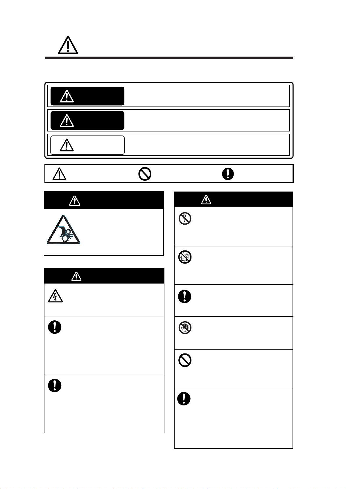
SAFETY INSTRUCTIONS
SAFETY INSTRUCTIONS
The operator of this equipment must read the safety instructions before attempting to operate
the equipment.
Indicates a hazardous situation which, if not avoided, will result in
DANGER
WARNING
CAUTION
death or serious injury.
Indicates a potentially hazardous situation which, if not avoided,
could result in death or serious injury.
Indicates a potentially hazardous situation which, if not avoided,
may result in minor or moderate injury.
Warning, Caution
Prohibitive Action
DANGER
Keep away from raise/ower
shaft in hull unit when it is
moving.
Gears in hull unit will cause seriou
injury.
WARNING
Do not open the equipment.
Only qualified personnel should work
inside the equipment.
Immediately turn off the power at the
switchboard if water leaks into the
equipment or something is dropped
into the equipment.
Mandatory Action
WARNING
Do not disassemble or modify the
equipment.
Fire, electrical shock or serious injury can
result.
Do not install the equipment where it
may be subject to rain or water splash.
Fire or electrical shock can result if water
leaks in the equipment.
Use the proper fuse.
Use of a wrong fuse can result in damage
to the equipment or cause fire.
Do not operate the equipment with
wet hands.
Electrical shock may result.
ii
Continued use of the equipment can cause
fire or electrical shock. Contact a FURUNO
agent for service.
Immediately turn off the power at the
switchboard if the equipment is emitting
smoke or fire.
Continued use of the equipment can cause
fire or electrical shock. Contact a FURUNO
agent for service.
Do not place liquid-filled containers on
the top of the equipment.
Fire or electrical shock can result if a liquid
spills into the equipment.
Turn off the power immediately
if you feel the equipment is behaving
abnormally.
Turn off the power at the switchboard if
the equipment becomes abnormally warm
or is emitting odd noises. Contact a
FURUNO dealer or agent for advice.
Page 5
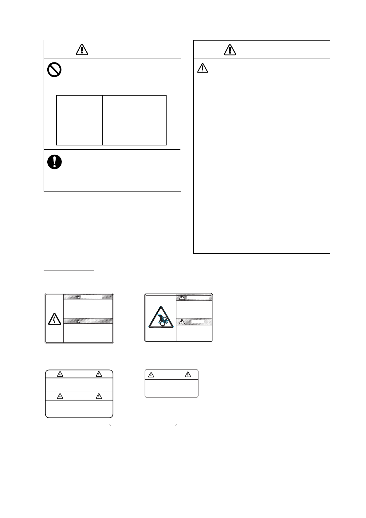
SAFETY INSTRUCTIONS
CAUTION
Maximum speed while the transducer is
projected and being raised or lowered
is as below, to prevent damage to the
transducer.
Projected Raising/
Lowering
800 mm stroke Max. 18 kt Max. 15 kt
1100 mm stroke Max. 18 kt Max. 15 kt
Replace anticorrosion zinc plate yearly.
Corrosion between the main shaft and
transducer may result if not replaced, allowing
water leakage and/or loss of transducer.
CAUTION
Observe the following precautions when
using industrial use lubricant.
Precautions
Q
Keep lubricant away from eyes. Wear protective
goggles when working with the lubricant.
The lubricant can cause inflammation of the eyes.
Q
Do not touch the lubricant. Wear protective gloves
when working with the lubricant. The lubricant can
cause inflammation of the skin.
Q
Do not ingest the lubricant. Diarrhea and vomiting
may result.
Q
Keep the lubricant out of reach of children.
Emergency procedures
Q
If the lubricant enters eyes, flush with clean water
about 15 minutes. Consult a physician.
Q
If the lubricant contacts skin, flush area with clean
water.
Q
If the lubricant is ingested, see a physician
immediately.
Disposal of lubricant and its container
Dispose of the lubricant and its container in accordance with local regulations. If you are unclear about
the disposal procedure, contact a FURUNO agent or
dealer for advice.
WARNING LABELS
Warning labels are attached to the units of the system. Do not remove the labels.
If a label is missing or damaged, contact a FURUNO agent or dealer about replacement.
DANGER
DANGER
Electrical shock hazard.
Do not remove cover.
No user-serviceable parts inside.
Turn off power before servicing.
And wait until charge lamp (green)
goes off and then remove cover.
Name: Warning Label
Type: 10-079-6144
Code No.: 100-310-880
WARNING
To avoid electrical shock, do not
remove cover. No user-serviceable
parts inside.
Name: Warning Label (1)
Type: 86-003-1011-1
Code No.: 100-236-231
Name: Warning Label
Type: 10-071-5313
Code No.: 100-291-160
WARNING
To avoid electrical shock,
do not remove cover.
No user-serviceable parts
inside.
Name: Warning Label (2)
Type: 03-129-1001-1
Code No.: 100-236-741
DANGER
Keep fingers away
from gears.
Shaft may cause injury.
Keep away froom
moving shaft.
iii
Page 6

SAFETY INSTRUCTIONS
v
This p age intentionally lef t blank.
i
Page 7

v
TABLE OF CONTENTS
FOREWORD ..........................................................................................................xi
SYSTEM CONFIGURATION................................................................................xiii
1. OPERATIONAL OVERVIEW.........................................................................1-1
1.1 Control Description ................................................................................................1-1
1.2 T urning the Power On/Off......................................................................................1-2
1.2.1 Turning the power on...................................................................................1-2
1.2.2 Turning the power off...................................................................................1-2
1.3 Lowering, Raising the Transducer.........................................................................1-3
1.3.1 Loweri ng th e transducer...............................................................................1-3
1.3.2 Raising th e transducer................................................................................. 1-3
1.4 Screen Brilliance....................................................................................................1-3
1.5 Control Panel Dimmer ...........................................................................................1-4
1.6 Display Mode, Di s play Divisi on.............................................................................1-6
1.6.1 Selecting a display mode.............................................................................1-6
1.6.2 Sample display mode pictures .....................................................................1-7
1.7 Adjusting the Gain................................................................................................1-13
1.8 Menu Overvi ew....................................................................................................1-14
2. HORIZONTAL MODE ....................................................................................2-1
2.1 Basic Operating Procedure ...................................................................................2-1
2.2 Indic ations and Marks............................................................................................2-2
2.2.1 Horizontal mode...........................................................................................2-2
2.2.2 Horizontal2 mode.........................................................................................2-3
2.3 Display Range........................................................................................................2-7
2.4 Tilt Angle.................................................................................................................2-8
2.4.1 Setting the tilt angle.....................................................................................2-8
2.4.2 Automatic tilt ................................................................................................2-9
2.4.3 Relation between bottom echo an d tilt angle.............................................. 2-11
2.4.4 Tilt angle for sur f ac e fish............................................................................2-12
2.4.5 Suitabl e til t angle........................................................................................2-13
2.5 Measuring Range and Bearing to a Target .........................................................2-14
2.6 Eliminating Weak Echoes....................................................................................2-15
2.7 Suppressing Bottom Tail......................................................................................2-17
2.7.1 Adjust AGC................................................................................................2-17
2.7.2 Decrease pul s e length ...............................................................................2-18
2.7.3 Adjust 2nd AGC...........................................................................................2-18
2.7.4 Adjust Near AGC........................................................................................2-19
2.8 Suppressing Bottom and Sea Surface Reflections in Shallow Waters..............2-20
2.9 Rejecti ng S onar Interference and Nois e.............................................................2-21
2.9.1 Identi fyi ng noi se source.............................................................................2-21
2.9.2 Interference rejector...................................................................................2-21
2.9.3 Changin g T x in terval..................................................................................2-22
2.9.4 Shiftin g Tx fr equency .................................................................................2-22
2.9.5 Noise limiter...............................................................................................2-23
Page 8

SAFETY INSTRUCTIONS
2.9.6 Echo average............................................................................................2-23
2.9.7 Reverberation reduction............................................................................ 2-23
2.9.8 Setting reference bearing for frequency change........................................ 2-23
2.9.9 Suppressing gain of bottom echo..............................................................2-23
2.9.10 Sidelobe suppression...............................................................................2-24
2.10 Adjusting Beamwidth...........................................................................................2-25
2.11 Tracking a Fish School (target lock) ...................................................................2-26
2.11.1 Selecting target lock type ......................................................................... 2-26
2.11.2 Fish school tracking mode....................................................................... 2-27
2.11.3 Position trackin g mode.............................................................................2-28
2.11.4 TARGET LOCK menu..............................................................................2-29
2.12 Detecting F ish Schools A ur ally ...........................................................................2-30
2.12.1 Selecting direction................................................................................... 2-30
2.12.2 Selecting audio sector............................................................................. 2-31
2.12.3 Automatic training.................................................................................... 2-32
2.12.4 Reverberation.......................................................................................... 2-32
2.13 Presentation Mode ..............................................................................................2-33
2.13.1 Presentation mode description ................................................................ 2-33
2.13.2 How to select a presentation mode.......................................................... 2-34
2.14 Fish Alarm............................................................................................................2-35
2.15 Relocating Fish School for Easy Observation....................................................2-37
2.16 Comparing F ish School Concentration...............................................................2-38
2.17 Measuring Fish School Speed............................................................................2-39
2.17.1 Entering fish marks.................................................................................. 2-39
2.17.2 Deleting fish marks.................................................................................. 2-40
2.18 Event Mark, Own Ship Position Mark.................................................................2-41
2.18.1 Entering an event mark............................................................................2-41
2.18.2 Entering an own ship position mark......................................................... 2-42
2.18.3 Deleting an event mark , ow n ship po sition mark...................................... 2-42
2.19 Net Course Mark .................................................................................................2-44
2.20 Observing Net Behavior......................................................................................2-45
2.21 Storing, Recalling Picture....................................................................................2-46
2.21.1 Storing the picture....................................................................................2-46
2.21.2 Reca lling stored picture........................................................................... 2-46
2.22 OTHERS Menu....................................................................................................2-47
2.22.1 Displaying the OTHERS menu................................................................ 2-47
2.22.2 OTHERS menu description ..................................................................... 2-48
2.23 Interpreting the Horizontal Display......................................................................2-51
2.23.1 Bottom echoes........................................................................................ 2-51
2.23.2 Fish schools............................................................................................ 2-52
2.23.3 Sea surface reflections............................................................................ 2-53
2.23.4 Wake.......................................................................................................2-53
2.23.5 Sidelobe echoes (false echoes)............................................................... 2-54
2.23.6 Noise and interference.............................................................................2-54
vi
Page 9

TABLE OF CONTENTS
3. VERTICAL MODE..........................................................................................3-1
3.1 Basic Operating Procedure ...................................................................................3-1
3.2 Vertical Mode Concept...........................................................................................3-2
3.2.1 Overview......................................................................................................3-2
3.2.2 Setting the vertical displ ay...........................................................................3-2
3.3 Vertical Mode Indications and Marks.....................................................................3-3
3.3.1 Typical vertical display.................................................................................3-3
3.3.2 V er ti cal bearing mark, tilt mark.....................................................................3-4
3.3.3 Trackball mark position reference mark........................................................3-5
3.4 Auto Train...............................................................................................................3-5
3.5 Display Range........................................................................................................3-6
3.6 Measuring the Range ............................................................................................3-6
3.7 Eliminating Weak Echoes......................................................................................3-7
3.8 Suppressing Bottom Tail......................................................................................3-10
3.8.1 Adjust AGC................................................................................................3-10
3.8.2 Decrease pul s e length ...............................................................................3-10
3.8.3 Adjust 2nd AGC...........................................................................................3-1 1
3.8.4 Adjust Near AGC........................................................................................3-1 1
3.9 Rejecti ng Interference and Nois e........................................................................3-12
3.9.1 Identi fyi ng noi se source.............................................................................3-12
3.9.2 Interference rejector...................................................................................3-12
3.9.3 Noise limiter...............................................................................................3-13
3.9.4 Shiftin g Tx fr equency .................................................................................3-13
3.9.5 Echo average.............................................................................................3-13
3.9.6 Reverberation reduction.............................................................................3-13
3.9.7 Suppressing gain of bottom echo...............................................................3-14
3.9.8 Suppressing sidelobes...............................................................................3-14
3.10 Adjusting Beamwidth ...........................................................................................3-15
3.11 Vertical Expansion Display ..................................................................................3-16
3.12 OTHERS Menu....................................................................................................3-17
3.12.1 Displaying the OTHERS menu.................................................................3-17
3.12.2 OTHERS menu description ......................................................................3-18
3.13 Applicat ion to Bonito and Tuna Fishing...............................................................3-21
3.13.1 Searching.................................................................................................3-21
3.13.2 Tracking...................................................................................................3-21
3.13.3 Approaching.............................................................................................3-21
3.13.4 Catching................................................................................................... 3-22
4. SLANT MODE................................................................................................4-1
4.1 Basic Operating Procedure ...................................................................................4-1
4.2 Indic ations and Marks............................................................................................4-2
4.2.1 Slant mode single display............................................................................4-2
4.2.2 Slant mode combination display...................................................................4-3
4.3 Display Range........................................................................................................4-7
4.4 Tilt Angle.................................................................................................................4-8
4.4.1 Setting the tilt angle.....................................................................................4-8
4.4.2 Automatic tilt ................................................................................................4-9
4.5 Auto Training........................................................................................................4-11
vii
Page 10

SAFETY INSTRUCTIONS
4.6 Measuring Range and Bearing to a Target.........................................................4-11
4.7 Eliminating Weak Echoes....................................................................................4-12
4.8 Suppressing Bottom Tail......................................................................................4-14
4.8.1 Adjust AGC................................................................................................4-14
4.8.2 Decrease pul s e length............................................................................... 4-15
4.8.3 Adjust 2nd AGC.......................................................................................... 4-15
4.8.4 Adjust Near AGC.......................................................................................4-16
4.9 Suppressing Bottom and Sea Surface Reflections in Shallow Waters..............4-17
4.10 Rejecting S onar Interference and Nois e.............................................................4-18
4.10.1 Identifying noise source........................................................................... 4-18
4.10.2 Interference rejector ................................................................................ 4-18
4.10.3 Changing Tx interval................................................................................ 4-19
4.10.4 Shifting TX frequ enc y............................................................................. 4-19
4.10.5
4.10.6 Echo average..........................................................................................4-20
4.10.7 Reverberation reduction .......................................................................... 4-20
4.10.8 Suppressing gain of bottom echo ............................................................4-20
4.10.9 Suppressing sidelo bes............................................................................. 4-20
Noise limiter............................................................................................. 4-20
4.11 Adjusting Beamwidth...........................................................................................4-21
4.12 Tracking a Fish School (target lock) ...................................................................4-22
4.12.1 Selecting target lock type......................................................................... 4-22
4.12.2 Fish school tracking mode.......................................................................4-23
4.12.3 Position tracking mode............................................................................ 4-24
4.12.4 TARGET LOCK menu..............................................................................4-25
4.13 Detecting F ish Schools A ur ally ...........................................................................4-26
4.13.1 Selecting direction................................................................................... 4-26
4.13.2 Selecting audio sector............................................................................. 4-27
4.13.3 Reverberation.......................................................................................... 4-27
4.14 Offcenter..............................................................................................................4-28
4.14.1 Manual offce nter...................................................................................... 4-28
4.14.2 Automatic offcenter..................................................................................4-29
4.15 Fish Alarm............................................................................................................4-30
4.16 Comparing F ish School Concentration...............................................................4-32
4.17 Measuring Fish School Speed............................................................................4-33
4.17.1 Entering fish marks.................................................................................. 4-33
4.17.2 Deleting fish marks.................................................................................. 4-34
4.18 Event Mark, Own Ship Position Mark.................................................................4-35
4.18.1 Entering an event mark............................................................................4-35
4.18.2 Entering an own ship position mark......................................................... 4-36
4.18.3 Deleting an event mark , ow n ship po sition mark...................................... 4-36
4.19 Net Course Mark .................................................................................................4-38
4.20 Observing Net Behavior......................................................................................4-39
4.21 OTHERS Menu....................................................................................................4-40
4.21.1 Displaying the OTHERS menu................................................................ 4-40
4.21.2 OTHERS menu description ..................................................................... 4-41
4.22 Interpreting the Slant Display..............................................................................4-44
4.22.1 Bottom echoes........................................................................................ 4-44
4.22.2 Fish schools............................................................................................ 4-45
viii
Page 11

TABLE OF CONTENTS
4.22.3 Sea surface reflections.............................................................................4-46
4.22.4 Wake........................................................................................................4-46
4.22.5 False echo by sidelobe............................................................................4-47
4.22.6 Noise and interference.............................................................................4-47
5. ECHO SOUNDER MODE..............................................................................5-1
5.1 Basic Operating Procedure ...................................................................................5-1
5.2 Typical Echo Sounder Dis plays.............................................................................5-2
5.2.1 Echo sounder 1 display................................................................................5-2
5.2.2 Echo sounder 2 (net recorder or echo sounder) display...............................5-3
5.2.3 Echo sounder combination mode (ES1 + ES2)............................................5-4
5.3 Selecting an Echo Sounder Mode.........................................................................5-6
5.4 Selecting Display Range........................................................................................5-8
5.5 Adjusting the Gain................................................................................................5-10
5.6 Picture Advance Speed........................................................................................5-1 1
5.7 Measuring Depth, Distance .................................................................................5-12
5.8 Comparing Fish School Concentration ...............................................................5-13
5.9 ES1 SETTING Menu Overvi ew...........................................................................5-15
5.10 ES2 SETTING Menu Overvi ew...........................................................................5-16
6. HISTORY MODE............................................................................................6-1
6.1 Basic Operating Procedure ...................................................................................6-1
6.2 Sample History Display..........................................................................................6-2
6.3 How to Interpret, Set the History Display ..............................................................6-3
6.3.1 Interpreti ng th e hi stor y display .....................................................................6-3
6.3.2 Setting the history marker............................................................................6-4
6.3.3 Setting the width of the history marker.........................................................6-5
6.3.4 Setting the picture advance mode................................................................6-6
7. NUMERIC/GRAPHIC DATA DISPLAY ..........................................................7-1
7.1 Full Num er ic/Graphic Data Display .......................................................................7-1
7.2 Abbreviated Numeric/Graphic Data Display .........................................................7-2
7.3 Numeric/Graphic Data Description........................................................................7-3
8. CUSTOMIZING THE EQUIPMENT................................................................8-1
8.1 User Menu..............................................................................................................8-1
8.1.1 Deleting items from user menu ....................................................................8-1
8.1.2 Programmi n g the user menu........................................................................8-2
8.2 Function Keys (F1-F6)...........................................................................................8-4
8.2.1 Executin g a function.....................................................................................8-4
8.2.2 Programmin g fu ncti o n keys..........................................................................8-6
8.2.3 Erasing programs.........................................................................................8-7
8.3 USER PROG Control.............................................................................................8-8
8.3.1 Selecting a user progra m.............................................................................8-8
8.3.2 Programmi n g th e US ER PROG control........................................................8-8
9. OTHERS MENU.............................................................................................9-1
9.1 ERASE MARKS menu...........................................................................................9-1
9.2 DISPLAY SETTING menu.....................................................................................9-2
9.2.1 Opening the DISPLAY SETTING menu........................................................9-2
ix
Page 12

SAFETY INSTRUCTIONS
9.2.2 DISPLAY SETTING menu description ......................................................... 9-2
9.3 ALARM & AUDIO menu ........................................................................................9-4
9.3.1 Opening the ALARM & AUDIO menu........................................................... 9-4
9.3.2 ALARM & AUDIO menu description.............................................................9-4
9.4 PRESET, MEMORY CARD menu.........................................................................9-5
9.4.1 Opening the PRESET, MEMORY CARD menu............................................ 9-5
9.4.2 PRESET, MEMORY CARD menu descr i p tion.............................................. 9-5
9.5 INITIAL SETTING menu........................................................................................9-6
9.5.1 Opening the INITIAL SETTING menu.......................................................... 9-6
9.5.2 INITIAL SETTING menu description............................................................ 9-6
10. MEMORY CARD OPERATIONS .................................................................10-1
10.1 Stor ing Image, Configurat ion...............................................................................10-1
10.2 Loading, Deleting Files........................................................................................10-3
10.3 Formatting Memory Cards ..................................................................................10-4
11. MAINTENANCE, TROUBLESHOOTING....................................................11-1
11.1 Preventive Maintenance...................................................................................... 11-1
11.2 Hull Unit Maintenance......................................................................................... 1 1-2
11.3 Fuse Replacement.............................................................................................. 11-3
11.4 Troubleshooting................................................................................................... 11-4
11.5 Warning Messages.............................................................................................. 1 1-5
11.6 Error Codes ......................................................................................................... 11-6
11.7 Stat us Messages................................................................................................. 11-7
11.8 Tests..................................................................................................................... 11-7
11.8.1 TEST menu...............................................................................................11-7
11.8.2 Board test.................................................................................................11-8
11.8.3 Panel test................................................................................................11-10
11.8.4 Test pattern.............................................................................................11-11
11.8.5 Rx test (For service technician)...............................................................11-12
11.8.6 Noise test (For service technician)..........................................................11-12
11.9 Raising the Transducer from the Hull Unit........................................................ 1 1-13
11.9.1 Raising the tr ansducer automatically ......................................................11-13
11.9.2 Raising the tr ansducer manually.............................................................11-14
MENU TREE......................................................................................................AP-1
SPECIFICATIONS.............................................................................................SP-1
INDEX.................................................................................................................IN-1
x
Page 13

FOREWORD
A Word to the Owner of the FURUNO FSV-84
Congratul ations on your choice of the FURUNO FSV-84 Color Scanning Sonar.
We are conf ident you will see w hy the FURUNO name has become synonymous
with quality and reliability.
For over 50 y ears FURUNO Electric Com pany has enjoyed an enviabl e
reputation for quality marine electronics equipment . This dedication to
excellenc e is furthered by our extensive global netw ork of agents and dealers.
This equi pm ent is designed and construct ed to meet the rigorous d em ands of
the marine environment . However, no m achine can perform its intended function
unless oper ated and maintained properly. Please carefully read and follow the
recommended procedures for oper ation and maintenance.
Thank you for considering and purch as ing FURUNO equipment .
Features
The FSV-84 is a full-ci r c le, multibeam electronic c olor scanning sonar which
detects and displays fish school s on a 21- inch non-glare, high-resolution color
monitor. (System also availabl e without monitor.)
The mai n features of the FSV-84 are
• Cylindrical + sphere transducer pr ovides 90 degrees vertical detection.
• Vivid 32- c olor echo strength dependent display for im pr ov ed recognition of
bottom, f ish school concentration, distribution and volum e.
• Fish schools can be searched from horizontal (range direc tion), vertical ( depth
direction) with vertical and half-circle features.
• Function k eys for direct access to desired menu item.
• User programs for one-touch setup of equipment.
• Menu-dri ve n operation.
• Fish hi s t ogr am s hows signal strength distribution of echo within estimate
mark.
• Various marks and alphanumeric fishing and navigation information for
intuitive operation.
• Memory cards for storage and replay of picture and settings.
xi
Page 14

FOREWORD
• Audio funct ion allows monit oring of echoes along user-selected area through
• Fish mark es timates fish speed.
• Fish est imate feature compares volume of two fish school s .
• Target lock automat ically tracks fish school.
• Net course m ark s hows probable drift of net against tide.
built-in loudspeaker.
xii
Page 15
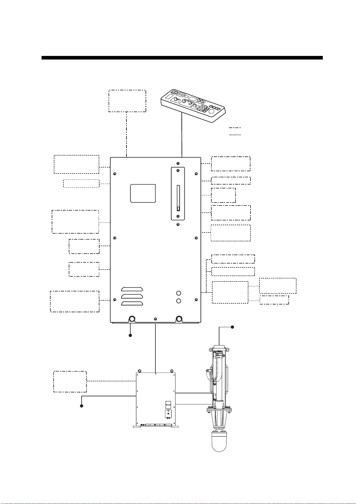
SYSTEM CONFIGURATION
System with locally supplied monitor
CONTROL UNIT
FSV-8401
External
Monitor
External equipment
Option
CONTROL UNIT
FSV-8401
Loudspeaker
Echo Sounder,
Current Indicator,
other
Navigator 1
Navigator 2
External
Interface CS-120A
(Note 1)
220-230 VAC,
Satellite
Compass
SC-50/110
100-115/
1φ, 50/60 Hz
PROCESOR UNIT
FSV-8402
TRANSCEIVER UNIT
FSV-841A
AD Converter
AD-100
Speed Log
Current
Indicator
Speed Log
E/S Interface
VI-1100A
Net Recorder
VI-1100A
Net Sonde
Junction Box
CS-170
220 VAC,
3φ, 50/60 Hz
HULL UNIT
FSV-8432
FSV-8442
VI-1100A
Net Sonde
100/110/115/
220/230 VAC,
1φ, 50/60 Hz
Note 1: Power Kit (option, installed in
processor unit) required to connect CS-120A.
Blackbox type configuration
xiii
Page 16
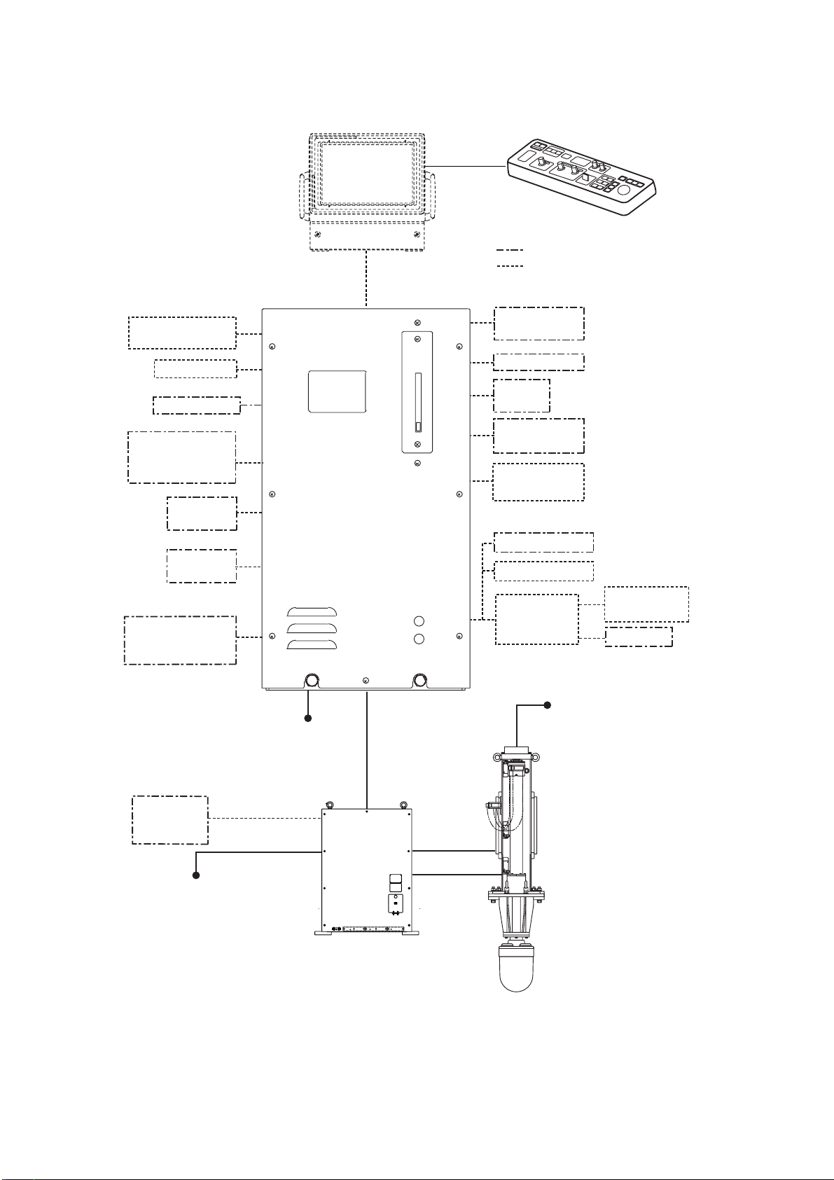
SYSTEM CONFIGURATION
v
System with FURUNO monitor
CONTROL UNIT
FSV-8401
Loudspeaker
Sub Monitor
Echo Sounder,
Current Indicator,
other
Navigator 1
MONITOR
UNIT
FSV-2400
PROCESSOR UNIT
FSV-8402
CONTROL UNIT
FSV-8401
External equipment
Option
AD Converter
AD-100
Speed Log
Current
Indicator
Speed Log
E/S Interface
VI-1100A
Navigator 2
External
Interface CS-120A
(Note 1)
220-230 VAC,
1φ, 50/60 Hz
Satellite
Compass
SC-50/110
100/110/115/
220/230 VAC,
1φ, 50/60 Hz
100-115/
TRANSCEIVER UNIT
FSV-841A
Net Recorder
VI-1100A
Net Sonde
Junction Box
CS-170
220 VAC,
3φ, 50/60 Hz
HULL UNIT
FSV-8432
FSV-8442
E/S Interface
VI-1100A
Net Sonde
Note 1: Power Kit (option, installed in
processor unit) required to connect CS-120A.
Standard type configuration
xi
Page 17
1. OPERATIONAL OVERVIEW
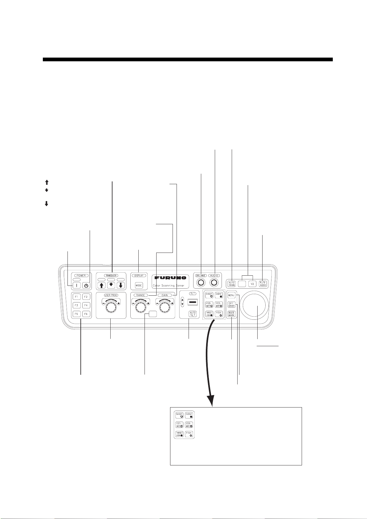
1.1 Control Description
Note that the [AUDIO] control is not operative from the 2nd control unit when two
control units are installed.
Automatic transducer train width
on audio bearing mark (horizontal
mode), vertical bearing mark
Raise, lower the transducer.
: Raises the transducer.
: Lowers the transducer
(mid protrusion).
: Lowers the transducer
(full protrusion).
Turns power off.
Turns power on.
Adjusts volume of internal
and external (option) loudspeaker.
Adjusts display brilliance
(supplied monitor only).
Adjusts receiver
sensitivity (horizontal and vertical modes).
Selects display
range (horizontal
and vertical modes).
Selects display
mode.
(vertical mode).
Off→±12°→ ±24°→±36°→Off
In vertical combination mode
switches between normal
and expansion display.
Displays range
and audio bearing marks
to monitor echoes along
audio bearing mark
(horizontal mode).
Execute assigned
program.
Selects user
program.
Selects mode (horizontal 1/
horizontal 2, or horizontal/
vertical, horizontal/half-circle)
for which to adjust sensitivity,
select range.
FSV-84
HSV
Sets transducer
tilt angle
(horizontal
mode).
V1/S
Deletes
trackballselected
mark.
Off centers the picture.
SHOOT: Displays net data.
EVENT: Inscribes event mark,
ESTIMATE 1, 2: Compares volume of
TARGET LOCK: Tracks fish school.
FISH: Measures speed of
Trackball
• Positions trackball
mark.
• Selects items,
options on menu.
Opens, closes menu.
own ship position mark.
two fish schools.
fish school.
Control uni t
1-1
Page 18
1. OPERATIONAL OVERVIEW
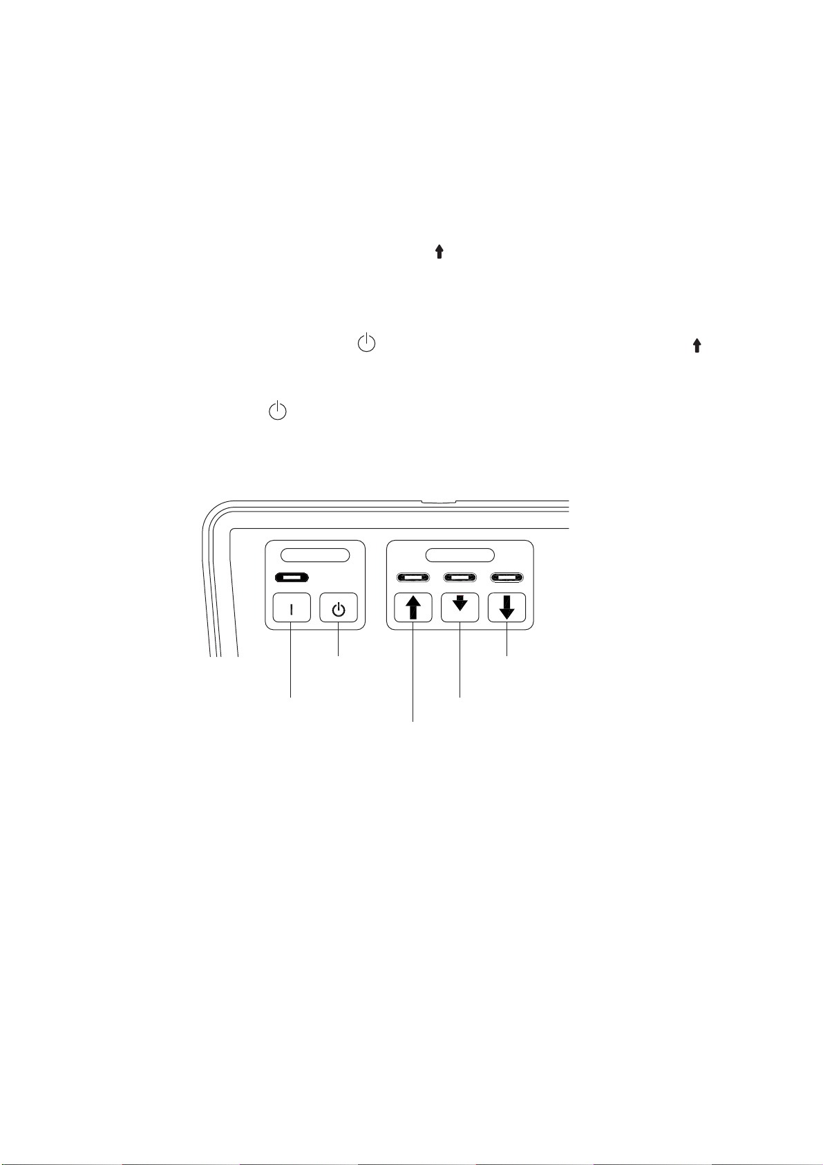
1.2 Turning the Power On/Off
1.2.1 Turning the power on
Press the POWER ON (|) switch. A beep sounds, the lamp above the switch
lights, and the last-used mode is presented.
1.2.2 Turning the power off
1. First retract the tr ansduc er with the [ ] key. The lamp above the switch blinks
whil e the t rans duc er is being raised and lights steadily when it is fully raised.
Note: Whil e r aising the transducer, the ship speed m us t be no more than 15
kts t o pr event damage to the transduc er and hull unit.
2. Press the POWER OFF (
) switch f or m or e than one second, after t he [ ]
key lights steadily.
Note: The transducer is automat ically retracted into the tank if the POWER
OFF (
) switch is pressed befor e r et r ac ting the transducer. However,
for safety purposes, make it a habit to retract the transducer bef ore
turning off the power.
POWER
POWER OFF
switch
POWER ON switch
Retraction key
TRANSDUCER
Full protrusion key
Mid protrusion key
1-2
POWER & TRANSDUCER controls
Page 19
1. OPERATIONAL OVERVIEW
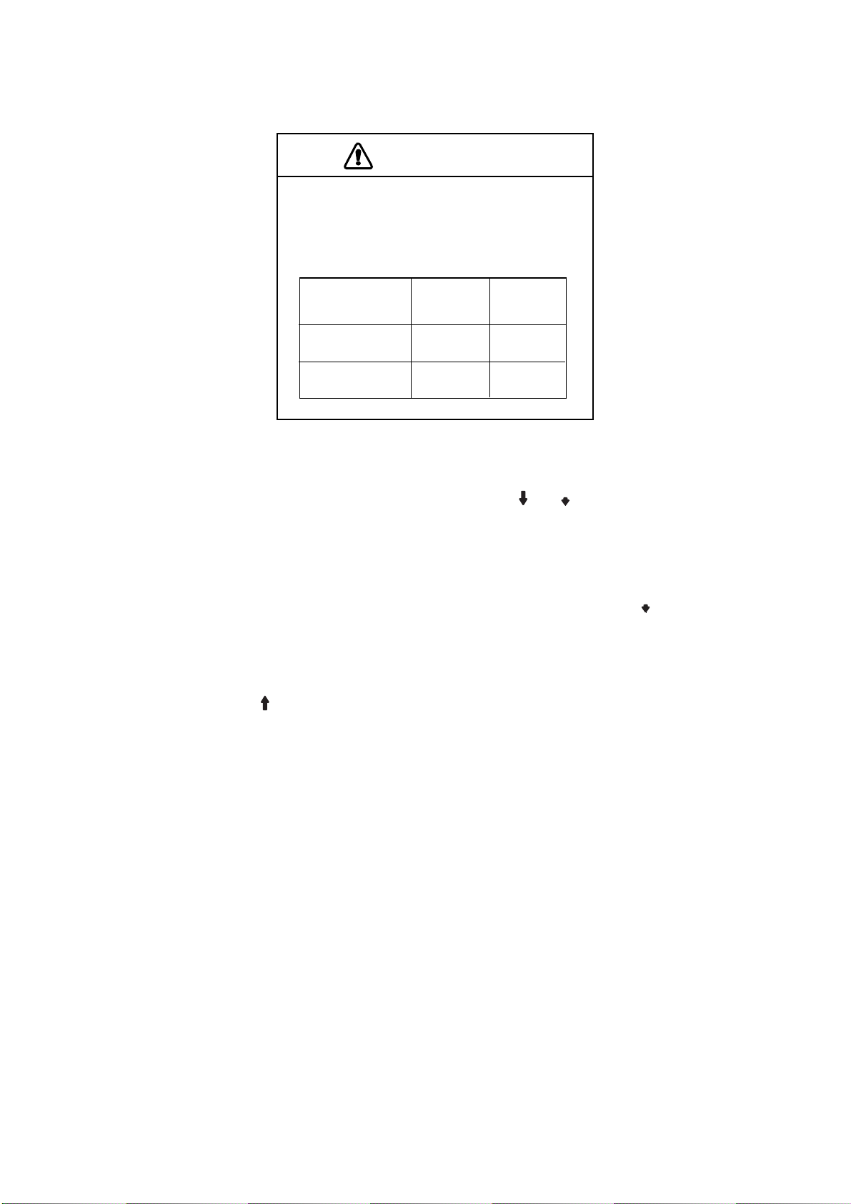
1.3 Lowering, Raising the Transducer
CAUTION
Maximum speed while the transducer is
projected and being raised or lowered
is as below, to prevent damage to the
transducer.
Projected Raising/
Lowering
800 mm stroke Max. 18 kt Max. 15 kt
1100 mm stroke Max. 18 kt Max. 15 kt
1.3.1 Lowering the tr an sd uc er
With the boat at the fishing ground, pres s the [ ] or [ ] k ey. The lamp above the
key pressed blinks during lowering and lights when the transducer is complet ely
lowered t o s elected protrusion distance. It takes about 21 seconds for full
protrusion in case of 800 mm stroke and 2 8 s econds in case of 1100 mm stroke.
In normal use fully lower the transduc er. If t he transducer bec om es entangled in
the net for some r eason, partial ly raise the transducer w ith the [ ] key. This
raises the t r ans ducer by 400 mm.
1.3 .2 Raising the transducer
Press the [ ] key to raise the transduc er. The lamp above the swit c h blinks while
the transducer is being raised and lights steadily w hen it is fully raised.
1.4 Screen Brilliance
The [BRILLIANCE] control adjusts scr een br illiance. A djust it to suit lighting
conditions.
Note: The brilliance of an external monitor cannot be adjusted with the
[BRILLIANCE] control. Use the as s ociated control on the monitor.
1-3
Page 20
1. OPERATIONAL OVERVIEW
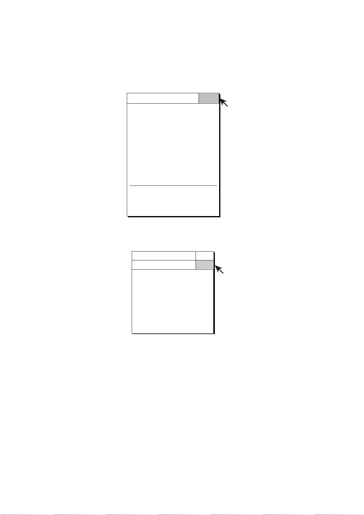
1.5 Control Panel Dimmer
The dim m er f or the control panel may be adjusted on the DISPLAY SETTING
menu as below.
1. Press the [MENU] key to open the main menu.
MENU QUIT
TX PULSE LENGTH-H : 9
TX POWER-H : 9
TVG-NEAR-H : 0
TVG-MEDIUM-H : 0
TVG-FAR-H : 0
AGC-H : 0
2ND AGC-H : 0
ECHO AVERAGE-H : 0
COLOR-H : COLOR 1
COLOR RESPONSE-H : COLOR CURVE 3
H-SCAN SETTING...
V-SCAN SETTING...
OTHERS...
Main menu (default)
2. Use the trackball to select OTHERS and press the [MENU] key.
MENU QUIT
OTHERS
ES1 SETTING...
ES2 SETTING...
ERASE MARKS...
DISPLAY SETTING...
ALARM & AUDIO...
PRESET, MEMORY CARD...
INITIAL SETTING...
QUIT
OTHERS menu
1-4
Page 21
1. OPERATIONAL OVERVIEW
3. Use the trackball to select DIS P LAY S ETT ING and press the [MENU] key.
MENU QUIT
OTHERS
DISPLAY SETTING
DISPLAY MODE...
MODE SELECTION : MODE KEY
TX/RX MODE : ALTERNATIVE
H2/S DISPLAY : LANDSCAPE
PRESENTATION MODE :HEAD UP
TM DISPLAY RANGE :1.6R
BEARING REF : SHIP HEADING
TILT LEVER : TILT
S AUTO OFF CENTER : OFF
H-SLICE WIDTH : 16
H-SLICE PICT ADVC : KP SYNC
NET COURSE MARK : ENTER
MANUAL DEGAUSS : EXECUTE
AUTO DEGAUSS : INT SENSOR
DIMMER : 10
KEY BEEP VOLUME : 5
QUIT
QUIT
DISPLAY SETTING menu
4. Select DIMMER with the trackball and press the [MENU] key to open the
dialog box.
QUIT
CANCEL
DIALOG BOX FOR SETTING NUMERIC DATA
Select (raise setting) or (lower setting) with
the trackball and press [MENU] key to change
setting. Select QUIT to finish; CANCEL to cancel
operation.
Dialog box for setting numeric v alue
5. Select S (raise setting) or T (lower setting) with the trackball.
6. Press the [MENU] key to change the setting.
7. Select QUIT wit h the trackball and press the [ M E NU] key.
8. Select QUIT at the top of the menu screen and press the [MENU] key to
close all menus.
1-5
Page 22
1. OPERATIONAL OVERVIEW
1.6 Display Mode, Display Division
This sonar provides a total of ten display mode selections: Horizontal,
Horizontal2, S, S combination, Vertic al1, Vertic al1, Vertical 2, V er tical1 + ES1
(echo sound er ) , Vertical 1 + ES2 (net recorder), Hi story, E S 1, ES2, and ES1 +
ES2. T he us er m ay preset as many modes as d es ired and select one with the
[MODE] key.
1.6.1 Selecting a display mode
Press the [MODE] key several tim es until the desired displ ay appears . The
default modes are Horizontal, Hor izontal1 + Horizontal2, Vertical1, Vertical 1 +
Vertical 2, and History. You can program the [MODE] key to show any or all of
the modes mentioned above. For f ur ther details, see DISPLAY MODE on page
9-2.
Note that the [MODE] key may be programmed to show a pull -down menu
instead. For further details, see MODE SELECTION on page 9-2. In this cas e
the procedure for mode selection is as follows:
1. Press the [MODE] k ey. The f ollowing pul l-down menu appears.
H1
S
H1&H2
H$S
V1
V1&V2
V1&ES1
V1&ES2
HISTORY
ES1
ES2
ES1&ES2
All modes enabled
H1
H1&H2
V1
V1&V2
HISTORY
Default setting
Mode selection menus
2. Use the trackball to select dis play mode desir ed.
3. Press the [MENU] key to display the selected mode.
1-6
Page 23
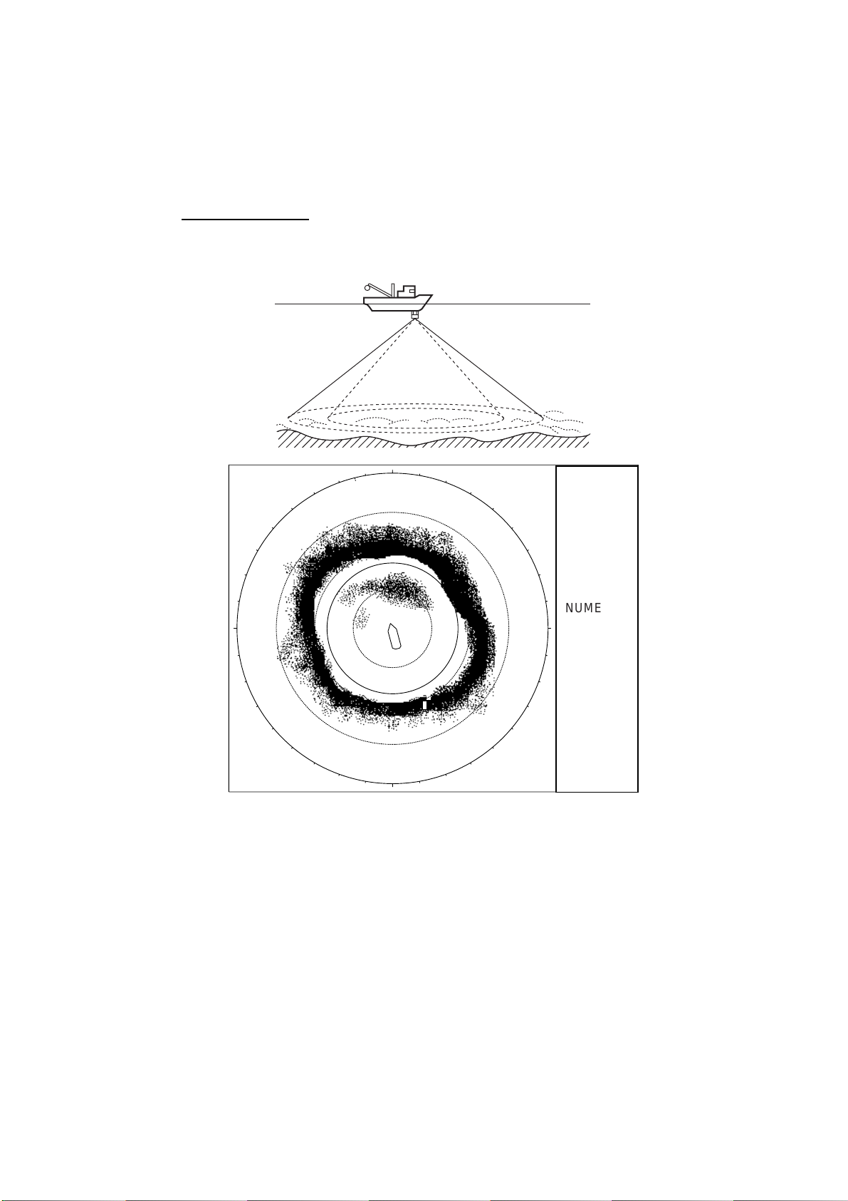
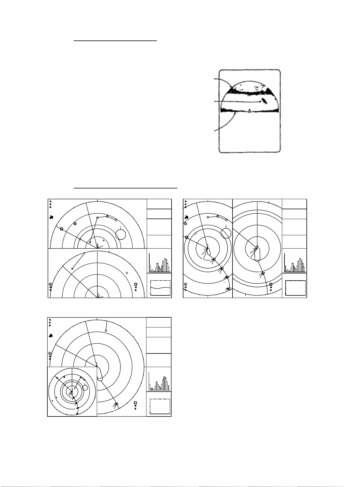
1.6.2 Sample display mode pictures
Below are typical pictures. For s ak e of brevity, indicati ons and mar k s are not
shown. For meaning of marks and indic ations, see respective indications and
marks descri ption illustration in applicable chapter.
Horizontal mode
This mode provides 360-degree coverage around the vessel and it is useful for
general sear c h. For further details, see Chapter 2.
N
1. OPERATIONAL OVERVIEW
NUMERIC/
W
S
GRAPHIC
E
DATA
DISPLAY
Horizontal mode display
1-7
Page 24
1. OPERATIONAL OVERVIEW
H2 mode
This mode provides two horizontal screens in one of the configurati ons s hown
below. The default configuration, LANDSCAPE, shows two horizontal displays
up and dow n. Other configurations available ar e as shown below. Desired
configurat ion may be chosen wi th H2 DISPLAY in the DI S P LAY S ETTING menu.
For further details, see Chapter 2.
N
N
N
1
85
1
2
3
1
3
2
3
2
1
2
2000
3
1
1
2
3
1
2
3
S
1
2
3
1
2000
2
3
S
NUMERIC/
GRAPHIC
DATA
DISPLAY
3
1
1
2
N
1
2
1
85
1
NUMERIC/
GRAPHIC
DATA
DISPLAY
PORTRAIT LANDSCAPE
N
NUMERIC/
W
W
N
1
2
1
3
2
3
1
2000
2
S
1
2
3
1
85
300
3
1
2
3
E
2
1
1
2
3
1
2
3
S
3
1
2
3
GRAPHIC
E
DISPLAY
DATA
W
N
NUMERIC/
GRAPHIC
1
2
3
300
W
S
N
1
2
3
1
3
2
3
1
2
1
2
2000
3
1
3
2
3
S
E
DATA
DISPLAY
1
85
E
2
1
1
2
3
1
2
3
1-8
LEFT INSET RIGHT INSET
Horizontal 2 display
Page 25
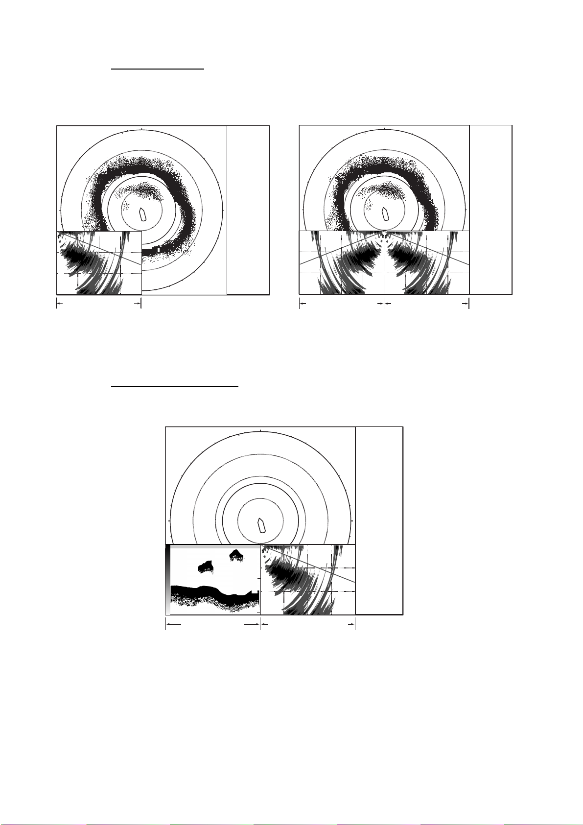
1. OPERATIONAL OVERVIEW
Slant mode, single display
The Sl ant mode shows a 180-degree cros s s ection, using chosen tilt angle and
train set t ing.
Bottom
Fish school
Sea surface reflection
Slant display (s ingle)
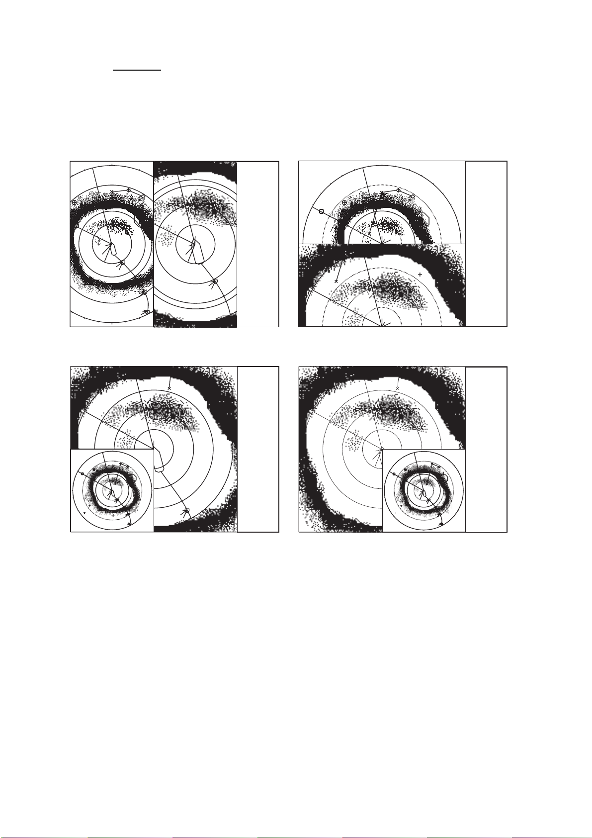
Slant mode, combination display
S
AUTO
8
5
1
R2000m
17˚
T
(21˚)
347˚
RO
3
10.0
G10.0
8
P
1
N
1
1
2
1
2
N
300
E
S
902m
9.83NM
5:32
678m
346m
B 278˚
W12m/s
1475m
156m
32˚52.150N
(164m)
132˚12.150E
B128˚
Landscape display (Slant mode on bottom half) Portrait display (Slant mode at right half)
902m
9.83NM
5:32
678m
346m
B 278˚
W12m/s
1475m
156m
32˚52.150N
(164m)
132˚12.150E
B128˚
W
W
2
N
1
2
3
1
2
3
1
1000
2
3
1
2
3
1
2
3
S
N-UP
H
1
85
N
1
R 1056m
B234˚
N-UP
3
1
2
3
R 1056m
B234˚
AUTO
S
RO
R 600m
H
R2000m
17˚T
(21˚)
G 10.0
P 8
R1000m
24˚T
357˚
7.5G
P 6
2975m
153m
S12.3kt
C256˚
12˚T
G 5.5
P 3
1975m
153m
S12.3kt
C256˚
HEADING
321˚
SHIP COURSE
335˚
SHIP SPEED
12.5kt
LAT/LON[DGPS] (000.000)
32˚52.150N
132˚12.150E
DEPTH
321m
WATER CURR
C1 1.2kt 342˚
C2 0.8kt 298˚
C3 0.4kt 256˚
NET DEPTH
S1 134m
S2 178m
S3 213m
FISH HISTOGRAM
1 Scan1
WATER TEMP
10.3˚C
12
10
8
HEADING
321˚
SHIP COURSE
335˚
SHIP SPEED
12.5kt
LAT/LON[DGPS] (000.000)
32˚52.150N
132˚12.150E
DEPTH
321m
WATER CURR
C1 1.2kt 342˚
C2 0.8kt 298˚
C3 0.4kt 256˚
NET DEPTH
S1 134m
S2 178m
S3 213m
E
FISH HISTOGRAM
1 Scan1
WATER TEMP
10.3˚C
12
10
8
902m
678m
346m
B 278˚
W12m/s
01020min
1475m
156m
(164m)
B128˚
01020min
9.83NM
5:32
1
2
3
32˚52.150N
132˚12.150E
N
N-UP
R2000m
AUTO
17˚T
(21˚)
G10.0
P 8
1
85
2
3
1
2
3
2
1
2
1000
3
1
1
2
3
1
2
3
S
3
S
N
HEADING
SH
R 1000m
24˚T
RO 357˚
G 4.0
G 7.5
P 6
1
1
500
3
2
3
975m
153m
S12.3kt
R 1056m
C256˚
B234˚
321˚
SHIP COURSE
335˚
SHIP SPEED
12.5kt
LAT/LON[DGPS] (000.000)
32˚52.150N
132˚12.150E
DEPTH
321m
WATER CURR
C1 1.2kt 342˚
C2 0.8kt 298˚
C3 0.4kt 256˚
NET DEPTH
S1 134m
S2 178m
S3 213m
FISH HISTOGRAM
1
1 Scan1
WATER TEMP
10.3˚C
12
10
8
01020min
Slant mode in inset
Slant display (combination)
1-9
Page 26
1. OPERATIONAL OVERVIEW
V1 and V2 modes
The V1 and V2 modes s how a vertical slice of the bearing selecte d by the
vertical bearing mark on the horizo ntal display. The verti c al 2 mode provides two
vertical slices. Chapter 3 discus s es the vertical mode.
N
N
W
1000 1500
500
500
1000
Vertical 1 Display
V1 + ES1 (or ES2) mode
The V1 + ES 1 ( or E S 2) c ombines the vertical 1 display with the picture from an
echo sounder or a net recorder.
2000
S
V1 mode
NUMERIC/
GRAPHIC
E
DATA
W
DISPLAY
Vertical 2 Display
V1 and V2 displ ay s
N
10001500 500 1000 1500
V 52°
500
500
2000
1000
S
Vertical 1 Display
V1 & V2 mode
NUMERIC/
GRAPHIC
E
DATA
DISPLAY
1-10
W
Echosounder
Display
(ES 1 or ES 2)
1000
500
0
500
2000
30
1000
60
S
1500
Vertical 1 Display
V1 & ES1 (ES2) display
NUMERIC/
GRAPHIC
E
DATA
DISPLAY
Page 27

1. OPERATIONAL OVERVIEW
History mode
The his tory mode shows the horizontal and history dis plays. Echo data for the
echoes within the history marker on the horizontal display scroll down t he history
display in the downward direction – the latest echoes at the top and the oldes t at
the bottom. This mode is useful for observing fish echoes over time. For further
details, see Chapter 6.
N
NUMERIC/GRAPHIC
DATA DISPLAY
W
S
Horizontal Display
History Display
E
History display
ES1 mode
The ES1 mode s hows the echo sounder dis play. F or further details, see Chapter
5.
N
NUMERIC/GRAPHIC
DATA DISPLAY
W
S
Horizontal Display
E
Echo Sounder
Display (ES1)
ES1 display
1-1 1
Page 28
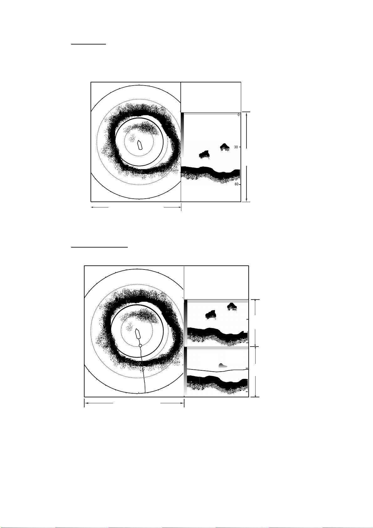
1. OPERATIONAL OVERVIEW
ES2 mode
The ES2 mode s hows the net recorder dis play . The net recorder display can
show t he downward l ook ing picture alone or both the downward and upward
looking pictures. Note that thi s m ode c an also show the echo sounder picture.
N
NUMERIC/GRAPHIC
DATA DISPLAY
W
E
Net Recorder
Display (ES2)
S
Horizontal Display
ES2 display (s hown: downward pic ture)
ES1 + ES2 mode
The ES1 + E S 2 m ode s hows the echo sounder and net recorder displays.
N
NUMERIC/GRAPHIC
DATA DISPLAY
0
30
Echo Sounder
W
E
Display (ES1)
1-12
60
0
Net Recorder
10
Display (ES2)
S
Horizontal Display
20
ES1 + ES2 display
Page 29
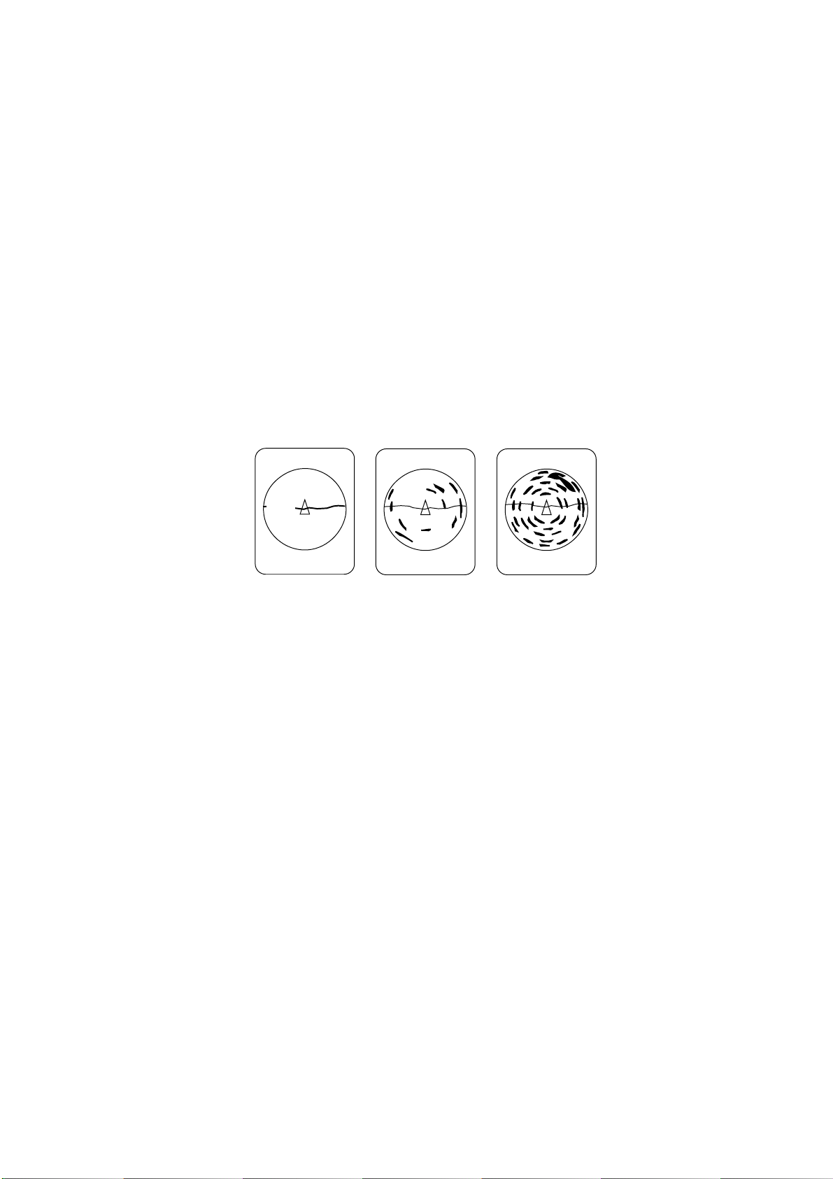
1.7 Adjusting the Gain
The [G AIN] control adjusts receiver gain (s ensitivity) for the hori z ontal, slant
vertical modes . Adjust it so fish echoes are clear ly displayed with minimal noise
on the screen. Too high a gain sett ing not only displays excess noise and makes
it difficult to discriminate wanted echoes but also causes bottom echo es to be
painted in strong colors, resul ting in echoes being maske d by bottom reflections.
Normally, set the control somewhere between positions 3 and 7.
1. If the horizontal and vertical m odes ar e ac tive, press the [HSV] k ey to show
the range and g ain indications of the mode you wish to adj us t in yellow.
Pressing t he [ HS V ] key changes the range and gain indicati on in yellow
between hor izontal1 and horizontal2, or horizontal and vertical, alternately.
2. Adjust the [GAIN] c ontrol.
New gai n s etting is mom entarily displayed in large charac ters at the top of
each display. Gain is always displ ay ed at the top right-hand corner of the
horizontal display and bottom on the vertical 1 display.
1. OPERATIONAL OVERVIEW
Gain too low
Exam ple of proper and improper gain set tings on the horiz ontal display
Gain proper
Gain too high
1-13
Page 30
1. OPERATIONAL OVERVIEW
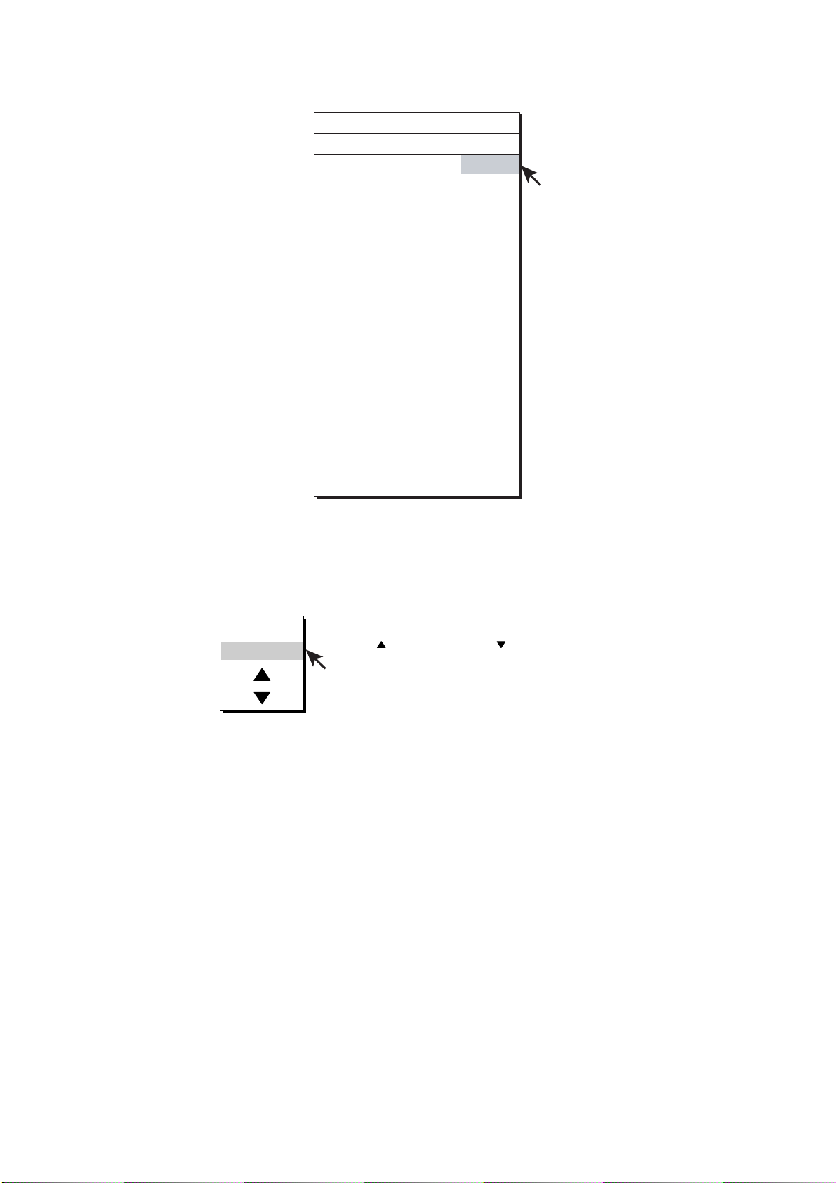
1.8 Menu Overview
Most operations are carried out through the menu. T his sec tion provides basic
menu operating information.
1. Press the [MENU] key to open the main menu.
USER MENU
This menu may be
programmed as
desired (max. 10
items). Shown here
are the items of the
default user menu.
Select menu with trackball,
and then press [MENU] key
to display. (Ellipsis mark
(...) indicates a menu.)
Note: The menus illustrations in this manual show curr ent menu settings with a
gray highlight. Actual equipment show s c ur r ent settings differently.
MENU QUIT
TX PULSE LENGTH-H : 9
TX POWER-H : 9
TVG-NEAR-H : 0
TVG-MEDIUM-H : 0
TVG-FAR-H : 0
AGC-H : 0
2ND AGC-H : 0
ECHO AVERAGE-H : 0
COLOR-H : COLOR 1
COLOR RESPONSE-H : COLOR CURVE 3
H-SCAN SETTING...
V-SCAN SETTING...
OTHERS...
Main menu
Select QUIT with trackball
and then press [MENU] key
to close menu.
1-14
Page 31

1. OPERATIONAL OVERVIEW
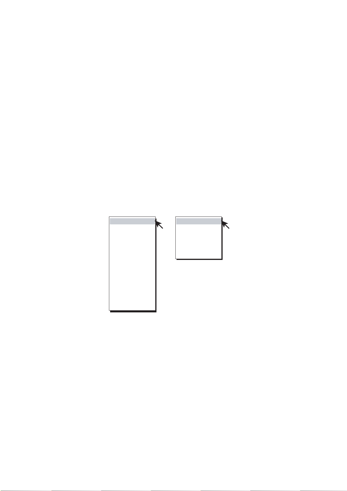
2. Select menu desired with the trackball and press the [MENU] key. (For
example, select the H-SCAN SETT ING menu.)
MENU TITLE
Select QUIT with trackball
and press the [MENU]
key to close menu
currently open.
Menu items and
current settings
MENU QUIT
H-SCAN SETTING
TX INTERVAL
TX PULSE LENGTH
TX POWER
TVG-NEAR
TVG-MEDIUM
TVG-FAR
NOISE LIMITER
REVERBERATION
SIDE LOBE SUPPRESS : 1
AGC
2ND AGC
NEAR AGC : 0
ECHO AVERAGE
INT REJECT
BOTTOM SUPPRESS : 0
FREQ SHIFT : 0
FREQ/BEARING SET : 180
OTHERS...
QUIT
: 9
: 9
: 9
: 0
: 0
: 0
: 2
: 0
: 0
: 0
: 0
: 0
Choose QUIT to close
all menus.
Pointer shows current
selection.
H-SCAN SETTING menu
Note: I n the S-mode combination dis play, the [HSV] key functions t o sw itch
between H- S CA N S E TTING menu and S-SCAN S E TTING menu.
1-15
Page 32

1. OPERATIONAL OVERVIEW
3. Select menu item desi r ed with the trackball and pres s the [MENU] key. (For
example, select NOISE LIMITE R.) A dialog box for the corresponding menu
item appears.
MENU QUIT
H-SCAN SETTING
TX INTERVAL
TX PULSE LENGTH
TX POWER
TVG-NEAR
TVG-MEDIUM
TVG-FAR
NOISE LIMITER : 2
REVERBERATION
SIDE LOBE SUPPRESS : 1
AGC
2ND AGC
NEAR AGC : 0
: 9
: 9
: 9
: 0
: 0
: 0
: 0
: 0
: 0
QUIT
QUIT
CANCEL
How to set numeric data
1. Select or as desired.
2. Press the [MENU] key to
change setting.
3. Select QUIT and press
the [MENU] key to finish.
ECHO AVERAGE
INT REJECT
BOTTOM SUPPRESS : 0
FREQ SHIFT : 0
FREQ/BEARING SET : 180
OTHERS...
: 0
: 0
H-SCAN SETT ING menu
4. Select S (raise setting) or T (lower setting) with the trackball and press t he
[MENU] k ey to change setting.
Note: For items having options the ar rows in the dialog box are replaced
with appropri ate options. For example the dialog box for s election of
picture advance speed in the echo sounder mode looks as below.
QUIT
CANCEL
1/1
1/2
1/4
1/8
SPEED SYNC
1-16
Echo sounder picture advance speed dialog box
5. Use the trackball to select QUIT from the dialog box and press t he [MENU]
key to clos e t he m enu.
6. Select QUIT at the top of the menu screen and press the [MENU] key to
close all menus.
Page 33

1. OPERATIONAL OVERVIEW
Note: I n the default setting, the s ub m enu item INITIAL S ETT ING in the
OTHERS menu and some items in t he INITIALIZATION menu are shown in red.
This means t heir items are locked t o pr eve nt accidental c hange of setting. When
you open one of these sub menus and select an item, the message bel ow
appears. To change the setting of the selected item, select YES and press the
[MENU] k ey, and the dialog box for the item selected appears. To escape, select
NO and press the [MENU] key. You may wish not to s how the message below,
that is, disable the setting protection feature. For further details, see ITEM
ATTRIBUTION on page 9-16.
CAUTION
THIS ITEM IS DEFINED AS NON-CHANGEABLE ITEM.
ARE YOUSURE TO CHANGE IT TO CHANGEABLE?
YES
NO
Caution for menu setting change
1-17
Page 34

1. OPERATIONAL OVERVIEW
This p age intentionally lef t blank.
1-18
Page 35

2. HORIZONTAL MODE
2.1 Basic Operating Procedure
4.
Select horizontal display.
2.
Lower transducer.
: Mid protrusion
3.
: Full protrusion
1.
Turn on power.
Adjust display brilliance.
6.
Select range.
FSV-84
HSV
8.
Set tilt angle.
7.
Adjust gain.
5.
Press to choose the screen (horizontal or
vertical, or horizontal1 or horizontal2) to
adjust gain and range.
V1/S
Control uni t
2-1
Page 36

2. HORIZONTAL MODE
2.2 Indications and Marks
2.2.1 Horizontal mode
The hori z ontal mode provides a 360° picture around the boat. To display the
horizontal mode picture, press t he [MODE] key.
Net shoot data
Distance run from shooting
Time from shooting
Trackball data
•
Slant range
•
Horizontal range
•
Depth
•
Relative bearing
or True bearing*
Wind speed, direction*
Latest event mark
Auto train mark
Audio bearing mark
Heading mark
North mark*
Own ship mark
Current (tide)
mark*
Range ring
Bearing scale
Event mark
Event mark data
•
Horizontal range
•
Present depth
•
Depth at measured
•
Relative bearing
or True bearing*
148m
142m
45m
°
B 115
W 12m/s
A
W
158m
48m
(210m)
°
B 330
Range
mark
Trackball mark
position
0.51NM
5:32
1
34°56.789N
123°45.678E
Range ring
data
2
Net
sonde mark*
Fish track
Target lock mark
Fish movement vector
N
1
2
3
150
3
1
2
3
2
S
Net shoot
mark
Range mark and
audio bearing
mark data
Presentation mode
Scan data
N-UP H
R 400m
AUTO
G10
P 8
(21
17°T
Range
Current auto tilt
°
)
Gain
User program no.
Fish mark
Latest fish mark
Line connecting
fish marks
Fish estimate mark
Fish estimate mark no.
1
85
2
1
3
1
1
2
3
1
2
3
R 146m
B 290
°
230m
70m
S 12.3kt
C 262
Fish estimate mark data
Trackball mark
E
Own ship position mark
Ship's track*
*
Requires appropriate
°
sensor.
Target lock/fish movement data
•
Horizontal range
•
Depth
•
Speed
•
Course
2-2
Horizontal mode indications and marks
Page 37

2.2.2 Horizontal2 mode
The H2 mode shows one of four kinds of hor izontal displ ay com binations:
LANDSCAPE, PORTRAIT, RIGHT INSET and LEFT INSET. Follow the
procedure b elow to select a combination display.
1. Press the [MENU] key to open the main menu.
MENU QUIT
TX PULSELENGTH-H : 9
TX POWER-H : 9
TVG-NEAR-H : 0
TVG-MEDIUM-H : 0
TVG-FAR-H : 0
AGC-H : 0
2ND AGC-H : 0
ECHO AVERAGE-H : 0
COLOR-H : COLOR 1
COLOR RESPONSE-H : COLOR CURVE 3
2. HORIZONTAL MODE
H-SCAN SETTING...
V-SCAN SETTING...
OTHERS...
Main Menu
2. Select OTHERS wit h the trackball and press the [MENU] key to open the
OTHERS menu.
MENU QUIT
OTHERS
ES1 SETTING...
ES2 SETTING...
ERASE MARKS...
DISPLAY SETTING...
ALARM & AUDIO...
PRESET, MEMORY CARD...
INITIAL SETTING...
QUIT
OTHERS menu
2-3
Page 38

2. HORIZONTAL MODE
3. Select DISPLAY SETTING and press the [MENU] key to open the DISPLAY
SETTING menu.
MENU QUIT
OTHERS
DISPLAY SETTING
DISPLAY MODE...
MODE SELECTION : MODE KEY
TX/RX MODE : ALTERNATIVE
H2/S DISPLAY : LANDSCAPE
PRESENTATION MODE :HEAD UP
TM DISPLAY RANGE : 1.6R
BEARING REF : SHIP HEADING
TILT LEVER : TILT
S AUTO OFF CENTER : OFF
H-SLICE WIDTH : 16
H-SLICE PICT ADVC : KP SYNC
NET COURSE MARK : ENTER
MANUAL DEGAUSS : EXECUTE
AUTO DEGAUSS : INT SENSOR
DIMMER : 10
KEY BEEP VOLUME : 5
QUIT
QUIT
DISPLAY SETTING menu
4. Select H2/S DISP LAY and pr es s the [MENU] key.
QUIT
CANCEL
LANDSCAPE
PORTRAIT
RIGHT INSET
LEFT INSET
Dialog box for setting combination
5. Select the desired combination with the t r ac k ball and press the [MENU] k ey.
6. Select QUIT and pres s the [MENU] key to finish.
2-4
Page 39

2. HORIZONTAL MODE
7. Select QUIT at the top of the menu screen and press the [MENU] key to
close all menus.
H1 display
3902m
3678m
1346m
B 278˚
W 12m/s
9.83NM
5:32
N
N-UP
R 4000m
H1
AUTO
17˚T
(21˚)
G10.0
P 8
1
H2 display
2975m
156m
(164m)
B 128˚
32˚52.150N
132˚12.150E
1
1
2
N
1
2
85
1
H2
R 1056m
B 234˚
R 1000m
24˚T
G 7.5
P 6
2975m
153m
S 12.3kt
C 256˚
The range, tilt, gain and user
program are set independently,
for each display.
LANDSCAPE
N
1
85
1
2
3
1
3
2
3
2
1
2
2000
3
1
1
2
3
1
2
3
S
N
NUMERIC/
1
2
3
3
1
2000
2
3
S
GRAPHIC
DATA
DISPLAY
PORTRAIT
2-5
Page 40

2. HORIZONTAL MODE
N
NUMERIC/
W
W
N
1
2
3
1
3
2
3
1
2000
2
S
1
2
3
1
85
300
E
2
1
2
3
1
1
2
3
1
2
3
S
3
1
2
3
GRAPHIC
E
DATA
DISPLAY
LEFT INSET
N
NUMERIC/
W
1
2
3
300
W
2
S
N
85
1
2
3
1
3
2
3
1
1
2
3
2
1
2
2000
3
3
1
1
2
3
1
2
3
S
GRAPHIC
E
DATA
DISPLAY
1
E
RIGHT INSET
2-6
Page 41

2.3 Display Range
The [RANGE] control select s the detection range. The r ange s elected is
momentarily displayed in large characters at the t op of the screen. Range is
always displayed at the top right hand corner of the screen.
BOTTOM
BOTTOM
Range concept
Below are the default ranges (in meters ) .
Range Setting 1 2 3 4 5 6
SEA SURFACE
SEA SURFACE
Range indicated
on the screen.
Range indicated
on the screen.
2. HORIZONTAL MODE
Range 100 200 400 600 800 1000
1. If the two horizont al displays, slant display or the horizontal and vert ical
displays are active, press the [HSV ] key to show the range and gai n
indicat ions of the horizontal mode in yellow. (This step is not necess ar y when
only t he hor izontal mode is active.) Range and gain indications are shown in
white on other modes
2. Operate the [RANGE] cont r ol to select desired range.
Note: Ranges may be preset as desired on the PRESET, MEMORY CARD
menu. For further details, see H/S-SCAN RANGE on page 9-5.
2-7
Page 42

2. HORIZONTAL MODE
2.4 Tilt Angle
The tilt angle shows the direction to which t he sound wave is emitted. When the
sound wave is em itted horizontally, t he tilt angle is said to be 0° and when
vertically, 90°. The tilt angle can be set between –5°(upward) t o 90° (downward),
in increm ents of 1°. The tilt angles for horizontal 1 and horizontal 2 modes can
be set indepe ndently of one another.
2.4 .1 Setting the tilt angle
To manually set a tilt angle, operate t he [TILT] control. Watch the tilt angl e
indicat ion and tilt angle indi c ator at the top right corner of the screen.
Select t ilt angle depending on t ar get fish. For surface fi s h s elect a shallow angle
(about 5°) and f or bottom fish, a deep angl e.
Transducer
Tilt angle setting range
-5-degree
0-degree horizontal direction (tilt angle 0-degree)
+90-degree
Note: The [TILT] control functions as a bear ing setting lever in the following
conditions:
• TILT LEVER in the DISPLAY SETTING menu i s set to “TILT & V1. ”
• The verti c al display is chosen in the vert ical mode.
2-8
Page 43

2.4.2 Automatic tilt
The [AUTO TILT] key automatically scans the tilt angle within the selected width.
This i s useful when you want to find the center depth of a fish school.
1. Press the [AUTO T ILT] k ey to select auto t ilt angle desired. Each tim e the
[AUTO TILT] key is pressed the auto ti lt angle changes in the following
sequence.
2. HORIZONTAL MODE
OFF → [±1 - 4°]→ [±2 - 6°]→ [±3 - 8°
OFF → [±2 - 10°]→ [±4 - 16°]→ [±6 - 20°
]
(Narrow)
]
(Wide)
Automat ic tilt range (narrow) with A UTO TILT key
Range Width (1) Width (2) Width (3) Period
60, 100
150, 200
300, 400
500, 600
700, 800
900, 1000
1100 and more
±4°∗
±2°
±1°
As above
As above
As above
As above
±6°∗
±4°∗
±2°
As above
As above
As above
As above
±8°∗
±6°∗
±4°∗
±3°
As above
As above
As above
Period: One trans.
Tilt angle changes
in 2° increments for
asterisk-marked
width;
1° increment s for
all other widths.
Automat ic tilt range (w ide) with AUTO TIL T key
Range Width (1) Width (2) Width (3) Period
60, 100
150, 200
300, 400
500, 600
700, 800
900, 1000
1100 and more
±10°
As above
As above
±8°
±6°
±4°
±2°
±16°
As above
As above
As above
±12°
±8°
±4°
±20°∗
As above
As above
As above
±16°
±12°
±6°
Period: One trans.
Period: Four trans.
Period: Two trans.
Same as above
Same as above
Same as above
Same as above
* For combinat ion modes H1/H2, H1/V, H1/S, two transmissions/ per iod at
depth between 60 and 200 m and one transmission/period for r ange 300 m
or greater.
Note: Wide tilt angle is activated from the SYSTEM menu. For further details,
contact your dealer.
2. Auto tilt begins, with the tilt angle set with t he [T ILT] cont rol as the center tilt
angle.
3. If necessary, change center ti lt angle with the [TILT] control.
2-9
Page 44

2. HORIZONTAL MODE
For example, when the [RANGE] cont r ol, [TILT] control and [ A UTO TILT] key are
set to 800 m, 8
transmiss ion as follows:
→9°→8°→7°→8°
8°
Note: The [AUTO TI LT] key is inoperative when the target lock function is acti ve
or is made active. Auto tilt is resumed once targ et lock is disabled.
° and widt h ( 1) r espec tively, the tilt angle changes at each
Tilt angle setting
Auto tilt concept
2-10
Page 45

2.4.3 Relation between bottom echo and tilt angle
The figure at the top of the next page illustrates how two fish schools “a” and “b”
are displayed on the screen using thr ee different tilt angles.
Case 1: Tilt angle 30° to 40°
This tilt angle will display the ent ire bottom since it i s c apt ur ed by the full width of
the beam. Fish school is obscured by the bottom.
Case 2: Tilt angle 10° to 20°
This tilt angle will only display half the bottom since it i s captur ed by only the
lower half of the beam. Fish school is located above the bottom.
Case 3: Tilt angle 0° to 5°
This tilt angle may or may not capture the bottom since the returning echo is
weak. Fish school is located close to the bottom.
2. HORIZONTAL MODE
Case 1
Fish school "a"
Bottom
Case 1
Points to consider
Case 2
Fish school "a"
Bottom
Case 2
Fish echo and t ilt angle
Case 3
Fish school "a"
Fish school "b"
Bottom
Case 3
• Normally, a vertically distributed fish school is a better sonar target than the
bottom, because it reflects t he transmitted pulse back toward the transducer.
• In case 3, both fish sc hools “a” and “b” are presented. Generally speaking,
however, midwater fish schools tend to be larger than bottom fish schools
and they are often displayed near the bottom on the displ ay.
• It is difficul t to detect bott om f ish when they are not dist r ibuted vertically.
2-1 1
Page 46

2. HORIZONTAL MODE
2.4.4 Tilt angle for surface fi s h
Sound emitted from the sonar transd ucer forms an oval-shaped beam with a
width of approximately 18° in t he vert ical direction (vertical beam width at -6dB).
The tilt angle is indicated by the angl e bet ween the centerline of t he beam and
the horizontal plane. Then, if the tilt angle is set to 0°, the centerline is par allel
with the sea sur face and one half of t he emitted sound goes upw ar d, toward the
sea surface.
This causes one half of the emitted sound to be reflected tow ar d the transducer
and displayed on the screen as sea surface reflections. When the sea is c alm,
since the sound is reflected just like a light hitting a mirror at a low incident angle,
it prop agates away and the sea surface reflections become negligible.
However if the sea is not calm enough, t hey will become domina nt and interfere
with observation of wanted echoes. To minimize these sea surface r eflections
and to search s urface fish schools effectively, the tilt angle is usually s et
between 8° and 9° so the upper portion of the beam becomes almost parallel
with the sea sur face. When the sea is rough, the tilt angle is sli ghtly increased to
lessen the affect of sea surface ref lections.
Sea surface
Tilt angle 0°
Tilt angle 8-9°
18°
Sea surface
18°
Tilt angle
2-12
Page 47

2.4.5 Suitable tilt angle
The figure below illustrates the relationship among tilt angle, depth and detection
range. Refer to it to find out the suitable tilt angle for a given d epth/detection
range.
2. HORIZONTAL MODE
Tilt angle and beam coverage (vertical beamwidth 18
(200)
20(40)
40(80)
60(120)
80(160)
100(200)
Depth (m)
200(400)
Vertical width of sonar beam
100 m100 m
18
°
100
31 m
200
(400)
200 m
62 m
° at -6dB
300 m
)
300
(600)
93 m
400
(800)
(-6dB)
Range(m)
Grey: Tilt 10
(1˚‑19˚)
Tilt 0
˚
(0˚‑9˚)
Tilt 5
˚
(0˚‑14˚)
Tilt 15
˚
(6˚‑24˚)
˚
Tilt angle and beam coverage
2-13
Page 48

2. HORIZONTAL MODE
2.5 Measuring Range and Bearing to a Target
Operate the t rac k ball to place the track ball mark on the target you want to
measure the r ange and bearing. The range, bearing and de pth to the target
appear at the upper left corner of the screen.
Trackball position may also be show in latitude and longitude. For further details,
see CURSOR POSITION on page 9-11.
TRACKBALL DATA
Slant range
Horizontal range
Depth
B Relative or
True bearing*
* Four display formats
available. See OTHER
MARKS on page 9-11.
B
34°56.789N
123°45.678E
Trackball mark
Heading line
Own ship mark
Trackball mark
L/L position
Location of trackball data
2-14
Page 49

2.6 Eliminating Weak Echoes
Echoes from targets such as bot t om and fish return to the transducer in order of
dist anc e to them, and when we compare their intensities at the transducer face,
those from nearer targets are generally stronger when their reflecting proper ties
are nearly equal. The sonar operat or will be quite inconveni enced if these
echoes are di r ectly displayed on t he s c r een, since he cannot judge the ac tual
size of t he target from the size of echoes displayed on the screen. To overcome
this i nc onvenience, use the TV G function. It compensates for propagation los s of
sound in water; amplificati on of echoes on short range is suppressed and
gradually increased as range incr eases so that similar targets are displayed in
the simil ar intensities irrespective of the ranges to them.
The FSV-84 has three TVG functions, NEAR, MEDIUM and FAR, and they
mainly c ompens ate for propagation loss on short, middle and long ranges
respectively, c entered at the ranges show n below. The higher the TVG set ting
the greater the amplification of echoes.
2. HORIZONTAL MODE
Near
About 100 m
Med
About 400 m
Far
About 800 m
Note: TVG distances can
be adjusted from the
menu.
See page 2-48.
Princi ple of TVG
The TVG is also used t o s uppr es s unwanted echoes and noi s e which appear in
a certain range area on the screen such as sea surface reflections and cruising
noise. To set TVG properly, do the following:
2-15
Page 50

2. HORIZONTAL MODE
1. Press the [MENU] key to open the main menu.
2. Select H-SCAN SETTING with the trackbal l and press the [MENU] k ey to
open the H-SCAN SETTING menu.
MENU QUIT
H-SCAN SETTING
TX INTERVAL
TX PULSE LENGTH
TX POWER
TVG-NEAR
TVG-MEDIUM
TVG-FAR
NOISE LIMITER
REVERBERATION : 0
SIDELOBE SUPPRESS : 1
AGC
2ND AGC
NEAR AGC : 0
ECHO AVERAGE
INT REJECT
BOTTOM SUPPRESS : 0
: 9
: 9
: 9
: 0
: 0
: 0
: 2
: 0
: 0
: 0
: 0
QUIT
FREQ SHIFT : 0
FREQ/BEARING SET : 180
OTHERS...
H-SCAN SETT ING menu
3. Select TVG-NEA R with the trackball and press the [MENU] key to show t he
dialog box.
QUIT
CANCEL
Numeric data entry dialog box
4. Use the trackball to select S or T and pres s t he [MENU] key to set. The
setting r ange is –5 to 5. The higher t he setting the greater the TVG effect .
5. Select QUIT and pres s the [MENU] key.
6. Repeat steps 3-5 to set TVG-MEDIUM and TVG-FAR.
When sea surface reflections or pl ank ton layers disturb the picture, decrease
appropriate TVG option by one or two steps.
7. Select QUIT at the top of the menu screen and press the [MENU] key to
close all menus.
2-16
Page 51

Note: When a fish school is locat ed on a long-range setti ng ( about 800 meters)
and is approac hing own ship do as fol lows:
Adjust t he tilt to keep the fish school in the center of the sonar beam, namely,
fish school is displayed in stronges t colors possible. Confirm that the fish echo
is displayed in the s am e c olor as it approaches. If the color suddenly changes
to weaker colors as the fish enters MEDIUM and NEAR areas, the TVG is
improperl y set. Adj us t the TVG. If this agai n pr oduc es s ea surface reflecti ons
and noise try to remove them wit h the AGC and noise limiter.
If the above procedure does not produc e s atisfactory results, the TVG curve
can be changed on the OTHERS sub menu i n the H-SCAN SETTI NG menu.
Also, adjust the setting of NEAR AGC, referring to next section.
2.7 Suppressing Bottom Tail
2.7.1 Adjust AGC
2. HORIZONTAL MODE
The AGC functions to aut om atically reduce the rec eiver gain only agains t s trong
echoes such as t he bottom or a large fis h s c hool. Since weak echoes remain
unaffected, a small fish s chool becomes easier to detect. Adjust it so that the
AGC works only on bottom reflections. Do not set it too high; weak echoes may
be missed.
1. Press the [MENU] key to open the menu.
2. Select H-SCAN SETTING menu and press the [MENU] key.
3. Select A GC and press the [MENU] key.
4. Adjust setting fr om the dialog box as appropriate and press the [MENU] k ey.
The setting range is 0-9. The higher the setting the great er the degree of
suppression.
5. Select QUIT and pres s the [MENU] key.
6. Select QUIT at the top of the menu screen and press the [MENU] key to
close all menus.
2-17
Page 52

2. HORIZONTAL MODE
2.7.2 Decrease pulse length
The puls e length determines the length of the transmission pulse emitted into t he
water. While a longer puls e is advantageous for long-range sounding, it has the
disadvantage of being poor in discrimination of tar gets, that is, the ability to
separate several closely located targets. When searching bottom fish, therefore,
it is useful to shorten the pulse length in order to separate fish echoes from
bottom reflections. Decrease the p ulse length setting t o s hor ten the pulse length.
For search of sur face and midwater fish in which bottom reflec tions are not so
strong, use the longest pulse lengt h “9” .
1. Press the [MENU] key to open the menu.
2. Select the H-SCAN SETTING menu and press the [MENU] key.
3. Select TX PULSE LE NG TH and press the [MENU] key.
4. Adjust setting fr om the dialog box as appropriate and press the [MENU] k ey.
The setting range is 0-9. The higher the setting the longer t he pulse length.
5. Select QUIT and pres s the [MENU] key.
6. Select QUIT at the top of the menu screen and press the [MENU] key to
close all menus.
2.7.3 Adjust 2nd AGC
While it is ideal to suppr ess bottom echoes with the AGC alone there ar e some
fishi ng gr ounds where this is not possible. (The high power s onar has the
advanta ge of long-range detection but this can also be a di s advantage, since
weaker ec hoes may be hidden in strong, unwanted echoes such as the bottom.)
If you cannot suppress bottom echoes or s ea s urface reflecti ons by the AGC
function alone, use the 2
For especially strong echoes, use a s etting of 3 or 4.
1. Press the [MENU] key to open the menu.
2. Select the H-SCAN SETTING menu and press the [MENU] key.
3. Select 2nd A GC and press the [MENU] key.
4. Adjust setting fr om the dialog box as appropriate and press the [MENU] k ey.
The setting range is 0-12. The higher the setting the great er t he s uppression.
5. Select QUIT and pres s the [MENU] key.
6. Select QUIT at the top of the menu screen and press the [MENU] key to
close all menus.
nd
A GC feature. Normally a s etting of 1 or 2 i s s uitable.
2-18
Page 53

2.7.4 Adjust Near AGC
When an excess ively strong echo is received in shallow or heavi ly sedimented
waters, you m ay not be able to suppress it by the TVG control alone. In this case,
a fish school whic h is displayed at more than 300 m away may disappear
gradually when the ship is approaching the fi s h s c hool.
Use the Near TVG feature to suppress t his strong echo. Normal ly set it between
3 and 4, however, this set ting depends on the sea are a. Do not set it too high; all
echoes (i nc luding noise) from near dis tance may be painted in red.
1. Press the [MENU] key to open the menu.
2. Select H-SCAN SETTING menu and press the [MENU] key.
3. Select NEAR AGC and press the [MENU] key.
4. Adjust setting fr om the dialog box as appropriate and press the [MENU] k ey.
The setting range is 0-10. The higher the setting the great er t he echo level of
near distance.
5. Select QUIT and pres s the [MENU] key.
6. Select QUIT at the top of the menu screen and press the [MENU] key to
close all menus.
2. HORIZONTAL MODE
2-19
Page 54

2. HORIZONTAL MODE
2.8 Suppressing Bottom and Sea Surface Reflections in Shallow Waters
In shall ow fishing gr ounds with hard or rocky bot t om , bottom reflecti ons often
interfer e with wanted fish echoes and t hey can not be eliminat ed s ufficiently wit h
the aforeme ntioned TVG and AGC functi ons , especially when the TILT is s et to a
larger angle in order to track fish sc hools approaching within 400 m. In such
cases try to reduce the output power by adjusting the Tx output inst ead of
turning down the gain. The pi c ture becomes clearer when output power is
reduced rather t han when the GAIN is decreased as illustrated below.
INCORRECT
METHOD
CORRECT
METHOD
Fish echo
Fish echo
TVG and AGC
adjusted with
TX POWER kept high
Reduce TX POWER
with GAIN kept
constant
weakened
Fish echo
How to suppress bottom and sea surface reflections in s hallow waters
1. Press the [MENU] key to open the menu.
2. Select the H-SCAN SETTING menu and press the [MENU] key.
3. Select TX POWER and pr es s the [MENU] key.
4. Adjust setting fr om the dialog box as appropriate and press the [MENU] k ey.
The setting range is 0-9. The higher the setting the higher t he Tx power.
5. Select QUIT and pres s the [MENU] key.
6. Select QUIT at the top of the menu screen and press the [MENU] key to
close all menus.
2-20
Page 55

2. HORIZONTAL MODE
2.9 Rejecting Sonar Interference and Noise
While observing the sonar picture, you may enc ounter occasional or i ntermittent
noise and int er f er ence. These are mostly caused by on-board electronic
equipment , engine or propeller noise, or electrical noise from other sonars being
operated ne ar by.
2.9.1 Identifying noise source
To eliminate noise effectivel y, you should first identify the noise source as
follows:
1. Stop transmis s ion on the TEST menu, by turning ON “TX” in the TEST menu,
and turn on the power of all on-board equipment one by one w hile observing
the pictur e. If noise appears on the sonar display, that equipment is emitting
noise. Check t he offending equipment’s ground and i ns tallation.
2. Run the boat at various speeds to check if the nois e is speed dependent.
If neit her of the above two steps has effect on the picture, adjust one of the
following:
2.9.2 Interference rejector
This cont rol is similar to the interference rejec tor on echo sounders and radars. It
is ef fective for rejecting random noise and sea surface reflections in rough sea
conditi ons . S et it so that noise is just eliminated. Do not use an unn ec es s ar ily
high setting since it may also rej ec t small wanted echoes.
1. Press the [MENU] key to open the menu.
2. Select the H-SCAN SETTING menu and press the [MENU] key.
3. Select INT REJE CT and press the [MENU] key.
4. Adjust setting fr om the dialog box as appropriate and press the [MENU] k ey.
The setting range is 0-3. The higher the setting the great er the degree of
interfer ence r ejection.
5. Select QUIT and pres s the [MENU] key.
6. Select QUIT at the top of the menu screen and press the [MENU] key to
close all menus.
2-21
Page 56

2. HORIZONTAL MODE
2.9.3 Changing Tx interval
When other so nar s nearby are operati ng the same transmissi on interval as that
of own s hip’s sonar, an interference ring appe ars on the display. To erase t he
interfer ence r ing from the screen, reduce the TX INT E RVAL on the H-SCAN
SETTING menu.
Interference
Tx interval high Tx interval lowered
How TX INTERVAL works
1. Press the [MENU] key to open the menu.
2. Select the H-SCAN SETTING menu and press the [MENU] key.
3. Select TX INTE RVAL and press the [MENU] key.
4. Adjust setting fr om the dialog box as appropriate and press the [MENU] k ey.
The setting range is 0-9. The higher the setting the longer t he Tx interval. The
setting 0 is same as the setting 9.
5. Select QUIT and pres s the [MENU] key.
6. Select QUIT at the top of the menu screen and press the [MENU] key to
close all menus.
Note: When the s onar is used in shall ow water with the range set between 60 m
and 200 m and Tx cycle at “9”, bot tom reflections caused by the 2nd-to-the-last
transmiss ion may appear on near ranges. Lower the Tx interval by 2 or 3 steps
to suppress them.
2.9.4 Shifting Tx frequency
2-22
If interfer enc e c annot be suppressed by the interference reject or or Tx interval,
shif t t he Tx frequency wit h FREQ S HIFT on the H-S CA N S E TTING menu.
1. Press the [MENU] key to open the menu.
2. Select the H-SCAN SETTING menu and press the [MENU] key.
3. Select FREQ SHIFT and press the [MENU] key.
4. Adjust setting fr om the dialog box as appropriate and press the [MENU] k ey.
The setting range is -65 to +65.
5. Select QUIT and pres s the [MENU] key.
6. Select QUIT at the top of the menu screen and press the [MENU] key to
close all menus.
Page 57

2.9.5 Noise limiter
Weak, unwanted reflections, colored light-bl ue or gr een, appear when the water
is dirty, plankton layers exists, or due to ship’s noise. The noise limiter can
reduce the effects of these unwanted reflections. Raising the setti ng caus es
unwanted r eflections to be displayed in colors of blue to background color.
Normally a setting of 3 or 4 is suf fi c ient.
1. Press the [MENU] key to open the menu.
2. Select the H-SCAN SETTING menu and press the [MENU] key
3. Select NOISE LIMITER and press the [MENU] key.
4. Adjust setting fr om the dialog box as appropriate and press the [MENU] k ey.
The setting range is 0-15. The higher the setting the great er t he degree of
suppression.
5. Select QUIT and pres s the [MENU] key.
6. Select QUIT at the top of the menu screen and press the [MENU] key to
close all menus.
2.9.6 Echo average
2. HORIZONTAL MODE
Adjusts echo afterglow, which can be usef ul for watching echo movem ent in the
H-SCAN SETTING menu. The set ting range is 0-7. The higher the number the
longer echoes r emain on the screen.
2.9.7 Reverberation reduction
You may choose the length of reverberati on f or the echo signal in the H- S CA N
SETTING menu. T he larger the value the shorter the reverberation, which
makes it easer to see the echo signal. The setting range is 0- 3.
2.9.8 Setting reference bearing for frequency change
The FREQ/ BEARI NG SET function in the H-SCAN SETTING menu i s provided
for avoiding interference from other equipment.
If noise ( interference) appears at a spec ific bearing, c hange the value of the
FREQ/BEARING SET in the H-SCAN SETTING menu. T he setting range is 0° to
358°.
Note: The FREQ/BEARING SET functi on is active only when the SIDELOBE
SUPPRESSION on the SYSTEM MENU is set to 1 or 2. For details, contact a
FURUNO agent or dealer.
2.9.9 Suppres si ng g ai n of bo tt om ech o
None-movi ng echoes such as bottom echo, plankton echo, etc ., may be
suppressed by t he set ting of BOTTOM SUPPRESS in the H-SCAN SET TING
menu (moving echoes such as fish school are not effect ed by this setting). T he
setting r ange is 0 to 10. The greater the s etting, the greater the suppression
level of the bottom, etc.
Note: Avoid using too high a setting - slow-moving fish school may be
suppressed as well.
2-23
Page 58

2. HORIZONTAL MODE
2.9.10 Sidelobe suppression
Sidelobes ar e fairly emissions gener ated outside the main beam. The energy of
the sidel obe is fairly weak but w hen the water is comparatively shallow and the
bottom is roc k y and hard, strong signals ar e detected by the sidelobe.
To reduce the ef fect of sidelobes, adjust SI DELOBE SUPPRESS from the
H-SCAN SETTING menu. The set ting range is –3 to +3 and the default setting is
0. The higher the setting the greater t he s idelobe suppressi on. If there is a
difference between the port and starboard side images , use a minus setting.
2-24
Page 59

2.10 Adjusting Beamwidth
The hori z ontal beamwidth of the Rx beam can be adjusted at the OTHERS
menu as below to raise the horizontal resolution.
1. Press the [MENU] key to open the menu.
2. Select H-SCAN SETTING and press the [M E NU] key.
3. Select OTHERS and press the [MENU] key.
MENU QUIT
H-SCAN SETTING QUIT
OTHERS
COLOR : COLOR 1
COLOR SETTING...
COLOR RESPONSE : COLOR CURVE 3
COLOR RESPONSE...
GAIN OFFSET : 0
SIGNAL LEVEL : 0
FAR TVG CURVE : TVG2
ABSORPTION COEFF : 23.5dB
TVG DISTANCE...
2ND AGC DISTANCE : 0m
NEAR AGC DISTANCE: 200m
SMOOTH ECHO RNG : 0
SMOOTH ECHO CIR : 0
GAIN CONTROL : NORMAL
BEAMWIDTH...
2. HORIZONTAL MODE
QUIT
.OTHERS menu
4. Select BEAMWIDTH and press the [MENU] key to open the dialog box.
MENU QUIT
H-SCAN SETTING
OTHERS
BEAMWIDTH
BEAMWIDTH A : 0
BEAMWIDTH B : 0
QUIT
QUIT
QUIT
5. Select BEAMWIDTH A and set appropriat e value. The higher the setting the
sharper the hor izontal resolut ion. The setting r ange is -4 to 5 plus AR and the
default setting is 0. A R m eans AUTO RANGE and it automatically adjusts
horizontal beamwidth acc or ding to the range.
6. Select BEAMWIDTH B and set appropriat e value. This controls echo beam
width by echo processing. The setting range is 0-5, and t he higher the setting
the greater the horizontal resolution.
7. Select QUIT and pres s the [MENU] key.
8. Select QUIT at the top of the menu screen and press the [MENU] key to
close all menus.
2-25
Page 60

2. HORIZONTAL MODE
2.11 Tracking a Fish School (target lock)
The target lock function automatically tracks a fish school so you won’t lose sight
of it on the di s play. Two types of target lock are available: position tracking
(TARGET MARK ) and fish school tracki ng ( FISH) and you may select one from
the menu as below. Default setting is “FISH. ” However, if the FSV-84 cannot
receive an echo of suffici ent level of echo, t r ack ing may not be performed.
2.11.1 Selecting target lock type
1. Press the [MENU] key to open the menu.
2. Select OTHERS and press the [MENU] key.
3. Select INITITAL S ETTING and press the [MENU] key.
4. Select YES and press the [MENU] key to conf irm the CAUTION indicated.
5. Select TARGET LOCK and pr es s the [MENU] key.
MENU QUIT
OTHERS
INITIAL SETTING
TARGET LOCK
QUIT
QUIT
QUIT
TRACKING METHOD : FISH
TILT INTERLOCK :
MARK INTERLOCK :
TRACKING DATA : H&V
THRESHOLD : 16
BOTTOM THRESHOLD : 3
TARGET SPEED LIMIT : 5kt
SMOOTHING : 0.5
TARGET SPD UPDATE : 60SEC
TARGET LOCK WINDOW : NORMAL
DIMENSION SETUP : 25t/1000m
VOLUME SETUP : 25t/1000m
TILT&RANGE
ESTIMATE MARK
2
3
TARGET LOCK m enu
6. Select TRACKING METHOD and press the [MENU] key to open the dial og
box.
QUIT
CANCEL
TARGET MARK
FISH
2-26
Target lock type dialog box
7. Use the trackball to select TARGET MARK or FISH as appropriate and press
the [MENU] key.
8. Select QUIT and pres s the [MENU] key.
9. Select QUIT at the top of the menu screen and press the [MENU] key to quit
all menus.
Page 61

2.11.2 Fish school tr ac ki ng m o de
The automatic echo target lock function automatically tracks the
operator-s elected fish school. When menu option TILT INTERLOCK on the
TARGET LOCK m enu ( pr evious page) is set to TILT & RANGE , and the tracked
fish school goes out of the zone in the ran ge direction, the range and tilt are
automatic ally controlled accor ding to the fish school posi tion.
1. Select FISH at step 7 in the procedure in section 2.11.1.
2. Use the trackball to select the fi s h s c hool to track on the horizontal display.
3. Press the [TARGET LOCK] key.
2. HORIZONTAL MODE
The target lock mark appears (
) on the fis h sc hool with a vector extendi ng
from its edge. This vector shows estimated t arget position after el apsed of
preset vector time. The t ar get lock mark is also inscri bed on the vertical
display, however no vect or appears.
• If the target is lost, t he target lock mark changes t o r ed c olor and the
tracking mode c hanges to positi on mode ( s ee next section) at that
position.
• When the FSV-84 detects and tracks the target again, the mode returns to
the fish s chool mode.
4. To turn off the tar get lock, press the [TARGET LOCK] key again.
Vector*
Target lock mark
Bearing mark
follows target
when target
lock is active.
Fish school's track*
* Turned on or off
from MARK DISPLAY
menu.)
TARGET LOCK DATA
2975m (Horizontal range)
153m (Depth)
S
12.3kt (Speed)
C
256° (Course)
Target lock mark and target lock data
2-27
Page 62

2. HORIZONTAL MODE
2.11.3 Position tracking mode
This mode tracks a stationary position (such as a reef ) using position data fed
from a navigator.
ABCD
Depth
E
How posit ion tracking mode target lock works
1. Select TARGET MARK at s tep 7 in the procedure in section 2.1 1.1.
2. Use the trackball to select the location to track.
3. Press the [TARGET LOCK] key to inscribe the target lock mark (
locati on s elected. The tar get lock mark is also inscribed on the vertical
display.
Tilt, range and vertical bear ing are automatical ly adjusted to track the location.
Using the figure above as an example, the target lock m ar k is placed on location
“E”. Then, the equipment remember s the location of “E ” and automatically
changes the t ilt angle as the ship moves f r om position A through D. As long as
the fish s chool “E” is stationary its echo i s kept displayed on the screen.
) at the
2-28
Page 63

2.11.4 TARGET LOCK menu
INITIAL SETTING
TARGET LOCK
TRACKING METHOD : FISH
TILT INTERLOCK :
MARK INTERLOCK :
TRACKING DATA : H&V
THRESHOLD : 16
BOTTOM THRESHOLD : 3
TARGET SPEED LIMIT : 5kt
SMOOTHING : 0.5
TARGET SPD UPDATE : 60SEC
TARGET LOCK WINDOW : NORMAL
DIMENSION SETUP : 25t/1000m
VOLUME SETUP : 25t/1000m
MENU QUIT
OTHERS
ESTIMATE MARK
QUIT
QUIT
QUIT
TILT&RANGE
2. HORIZONTAL MODE
2
3
TARGET LOCK m enu
TRACKING METHOD: Selects trac k ing method, target m ar k ( pos ition) or fish.
TILT INTERLOCK: Provides autom atic change of tilt angle and range or tilt
angle during target lock.
MARK INTERLOCK: Selects items of numeric/graphic data display during target
lock operation.
TRACKING DATA: Selects which tracking data to use; horizontal, or both
horizontal and vertical.
THRESHOLD: Selects the weakest echo c olor number to track . The setting
range is 1 to 30.
BOTTOM THRESHO LD : When a target is judged as a bottom echo, raise this
setting to differentiate bot t om from target. T he setting range is 0 to 5. T he s etting
range is 0 to 5.
TARGET SPEED LIMIT: Sets maximum fish speed to track. The setting range i s
1kt to 15kt.
SMOOTHING: Sets smoothing rat e for fish speed data. The setting range is 0. 0
to 1.0.
TARGET SPD UPDATE: Sets fish speed data update interval am ong 15, 30, 45
and 60 seconds .
TARGET LOCK WINDOW: Selects si ze of target lock detection area; normal ,
large, l ar gest. However , this area is not displ ayed on the screen.
DIMENSIO N S E TUP: Sets dimension constant for calc ulation of fish school
tonnage from the fish school dimension.
VOLUME SETUP: Sets volum e c ons tant for calculation fish school tonnage from
fish school volume.
2-29
Page 64

2. HORIZONTAL MODE
2.12 Detecting Fish Schools Aurally
Sometimes you may be preoccupied with other tasks and unable to concentrate
on watc hing the sonar picture. In suc h c as es it would be a good choice to us e
the audio function. This func tion enables you to monitor echoes from fish
schools and seabed through the bui lt-in speaker.
After y ou’v e become accustomed to mo nitoring fish aural ly, you should be able
to detect a f ish school from a range longer t han you can detect it on the screen.
In addition you may judge whether t he fish school is approachi ng or going away;
the tone becom es higher when the school is approaching and lowers when the
school is going away .
2.12.1 Selecting direction
In the defaul t setting, the audio f unction is on and the audio sector is 30°.
1. Operate the trackbal l to place the trackball mar k on the direction you w ant to
monitor t hrough the speaker.
2. Press the [R/B AUDIO] key.
The audio bear ing mark appears on the b ear ing selected, in a 30°, 60°, 90°,
180° or 330° sect or centering the audio bear ing mark. Echoes are m onitored
through the s peaker. You can adjust speaker volume with the [AUDIO] control.
Note: When the trackball mark is placed near own ship mark and the [R/B
AUDIO] key is pressed, the range mark and the related data at the bottom of the
screen are erased. Note that the audio bearing is erased when “ A UDIO” on the
ALARM & AUDIO menu is turned off.
A
Audio bearing mark
Range mark
R 400m
B 45°
Range and audio bearing
marks data
2-30
Range and audi o bearing marks
Page 65

2.12.2 Selecting audio sector
1. Press the [MENU] key to open the menu.
2. Select OTHERS and press the [MENU] key.
3. Select A LA RM & AUDIO and pres s the [MENU] key.
MENU QUIT
ALARM & AUDIO
FISH ALARM : OFF
ALARM LEVEL : 16
ALARM ZONE...
SHIP SPEED ALARM : ON
AUDIO : ON
AUDIO SECTOR : 30°
REVERBERATION : 0
ALARM & AUDIO menu
2. HORIZONTAL MODE
QUITOTHERS
QUIT
4. Select A UDIO SECTOR and press the [MENU] key to open the dialog box.
QUIT
CANCEL
30°
60°
90°
180°
330°
Audio sector dialog box
5. Select desired audio sector among 30°, 60°, 90°, 180°, 330° and press t he
[MENU] k ey.
6. Select QUIT and pres s the [MENU] key.
7. Select QUIT at the top of the menu screen and press the [MENU] key to
close all menus.
2-31
Page 66

2. HORIZONTAL MODE
2.12.3 Automatic training
You may automat ically scan the audio sector and audio bearing mark i n the
sector of 12°, 24° or 36° as bel ow.
1. First acti vate the range and audio bearing marks with the [R/ B AUDIO] key.
2. While pressing and holding down the [AUTO TRAIN] key, press the [R/B
AUDIO] key to select des ired auto train sector among 12°, 24°, 36° and OFF.
Watch the auto train mark to k now the currently selected sector. The chosen
sector appear s in large characters f or five seconds at the top of the screen.
To turn off automatic traini ng, select OFF at step 2.
Auto train mark
Auto train sector
A
Audio bearing
mark
Indications related to automatic training
2.12.4 Reverberation
You may choose the length of reverberati on f or the audio signal. The larger the
value the longer the rev erberation, which makes it easer to hear the audio signal.
The setting range is 0-9 and the default setting is 0.
2-32
Page 67

2.13 Presentation Mode
2.13.1 Presentation mode description
This sonar has four presentati on modes, head-up, nort h- up, c ourse-up and true
motion, and you may select one with PRESENTATION MODE in the OTHERS DISPLAY SETTING menu.
2. HORIZONTAL MODE
N
Head-up
N
N
North-up True Motion
Course-up
N
Presentation modes
Head-up: The display is oriented toward ship’s heading. Own ship positi on is
fixed at the screen center. Echoes from fish and the bottom move on the screen
relati ve to own ship’s movement . This mode is useful f or gener al use.
North-up: The display is oriented so North is at the top of the screen. Own ship
positi on is fixed at the screen center and own s hip mar k pivots with ship’ s
movement. Echoes from fish and the bottom move on the screen relative to own
ship’s movement.
Course-up: The display is oriented according to course. Own ship position is
fixed at the screen center. Echoes from fish and the bottom move on the screen
relati ve to own ship’s movement . Targets are displayed at ship’s bow.
True Motion: Stationary objects are fixed and own ship and fis h ec hoes m ove
on the displ ay in accordan c e with their true cour ses and s peeds. Thus you can
observe own ship and fish echo movement with respect to the bottom . This
mode requir es speed and heading data. When own ship m ark r eac hes an edge
of the of f-center effective area it is automatically returned to the sc r een center as
below.
NN
Offcenter
effective area
(a) Own ship mark reaches
an edge of offcenter
effective area
(b) Own ship mark is automatically
returned to screen center
Automatic return of own ship mark in true motion
2-33
Page 68

2. HORIZONTAL MODE
2.13.2 How to select a presentation mode
1. Press the [MENU] key to open the menu.
2. Select OTHERS and press the [MENU] key.
3. Select DISPLAY SETTING and press the [MENU] key.
MENU QUIT
OTHERS
DISPLAY SETTING
DISPLAY MODE...
MODE SELECTION : MODE KEY
TX/RX MODE : ALTERNATIVE
H2/S DISPLAY : LANDSCAPE
PRESENTATION MODE :HEAD UP
TM DISPLAY RANGE : 1.6R
BEARING REF : SHIP HEADING
TILT LEVER : TILT
S AUTO OFF CENTER : OFF
H-SLICE WIDTH : 16
H-SLICE PICT ADVC : KP SYNC
NET COURSE MARK : ENTER
MANUAL DEGAUSS : EXECUTE
AUTO DEGAUSS : INT SENSOR
DIMMER : 10
KEY BEEP VOLUME : 5
QUIT
QUIT
DISPLAY SETUP menu
4. Select PRESENT ATIO N MODE and press the [MENU] key to open the dialog
box.
QUIT
CANCEL
HEAD UP
NORTH UP
COURSE UP
TRUE MOTION
Presentation mode dialog box
5. Select presentation mode desired and press t he [MENU] key.
6. Select QUIT and pres s the [MENU] key.
7. Select QUIT at the top of the menu screen and press the [MENU] key to quit
all menus.
Note: The true motion display range may be s et to 1.3 or 1.6 times the r ange
with TM DISPLAY RANGE on the DISPLAY SETTING sub menu.
2-34
Page 69

2.14 Fish Alarm
The fish alarm sounds the aural al ar m when a fish echo above a preset s trength
enters the op er at or - set alarm zone.
1. Press the [MENU] key to open the menu.
2. Select OTHERS and press the [MENU] key.
3. Select A LA RM & AUDIO and pres s the [MENU] key.
MENU QUIT
QUITOTHERS
ALARM & AUDIO
FISH ALARM : OFF
ALARM LEVEL : 16
ALARM ZONE...
SHIP SPEED ALARM : ON
AUDIO : ON
AUDIO SECTOR : 30°
REVERBERATION : 0
QUIT
2. HORIZONTAL MODE
ALARM & AUDIO menu
4. Select FISH ALARM and press the [ME NU] key to open the dialog box.
QUIT
CANCEL
OFF
ON
Fish alarm status dialog box
5. Select ON, select QUIT and then press the [M ENU] key. To cancel the fish
alarm, select OFF instead of ON.
6. Select A LA RM ZONE and press the [ME NU] key.
7. Operate the trackbal l to place the trackball mar k on the starting point of the
alarm zone.
8. Press the [MENU] key.
9. Rotate the trackball clockwise to sel ec t the ending point. The display paints a
fan-shaped alarm zone.
10. Press the [MENU] key.
11. Select QUIT at the top of the menu screen and pr es s the [MENU] key to
close all menus.
2-35
Page 70

2. HORIZONTAL MODE
Note 1: There must be at least t hr ee degr ees difference b etween the starti ng
and ending poi nts to get a fan-shaped alarm zone as shown i n ( a) and ( b) below.
Otherwise, the unit paints a 360-degree alarm zone as in (c) w her e there is less
than 3 degrees between the star ting and ending points and (d) where the
bearing marker has been rotated one full turn.
<<ALARM ZONE SETTING>>
PLACE CURSOR AT STARTING POINT
AND PRESS MENU KEY TO SET.
PRESS R/B KEY TO CANCEL.
<<ALARM ZONE SETTING>>
PLACE CURSOR AT ENDING POINT
AND PRESS MENU KEY TO
COMPLETE ALARM ZONE SETTING.
How to set the fish alarm zone
More than 3˚
Within 3˚
(a) (b) (c) (d)
How to creat e desired alarm zone
Note 2: The echo strength which triggers the alarm can be set with ALA RM
LEVEL on the ALARM & AUDIO menu. The setting range is 0-30.
This value corr esponds with t he number of 32-echo colors.
Note 3: To disable the fish alarm , c hoos e OFF at step 5 in the procedur e on the
previous page.
2-36
Page 71

2. HORIZONTAL MODE
2.15 Relocating Fish School for Easy Observation
Use the offcenter feature to relocate a fish school.
1. Operate the trackbal l to place the trackball mar k on the position where y ou
want to relocate the own ship mark.
2. Press the [OFF CENT E R] key.
3. To move the own ship mark bac k to the screen center, press the [OFF
CENTER] k ey again.
Fish school
Fish
Press [OFF CENTER] key
Own ship
mark
school
Set trackball
mark here,
for example.
Own ship mark
moves to trackball
mark position.
How to use offcenter
2-37
Page 72

2. HORIZONTAL MODE
2.16 Comparing Fish School Concentration
You can get an estimate of the volume of tw o fi s h s c hools by using the tw o
ESTIMATE keys as follows:
1. Operate the trackbal l to place the trackball mar k on a fish school, and then
press the [ES T IMAT E 1] key.
2. The estimate mark appear s on the fish school. Relat ive volume is shown by a
figure between 0 and 100, below t he es timate mark. When the area inside
the mark is filled in reddish brown, volume figure is said to be “100”.
3. Operate the trackbal l to place the trackball mar k on another fish school and
press the [ES T IMAT E 2] key.
4. Compare estimate figures for each fish sc hool by observing estimate m ar k
data and the f ish histogram.
5. To turn off the estimate marks press their respective keys.
Estimate mark 2
North
mark
Estimate
mark 1
N
2
1
85
W
35
!
"
NUMERIC/
#
GRAPHIC
E
1
SCAN
DATA
DISPLAY
2
SCAN
°
°
°
°
°
°
°
S
$
°
$
Estimate mark 2 data
Estimate mark 1 data
Estimate marks and their data
2-38
Page 73

2.17 Measuring Fish School Speed
To ensure a good haul, it is important to estimate the direction and speed of the
fish school before shooting the net . You can do this with t he [FISH] key. With
tidal c ur rent data plus fish speed data, you can determine the timing of the net
shooting more efficiently. T his function r equires speed and heading data.
2.17.1 Entering fish marks
1. Place the trackball m ar k on t he c enter of a fish school, and then press the
[FISH] key. The latest fish mark (
2. Wait 1 to 2 minutes.
3. Place the trackball m ar k on t he s am e fish school selec ted in step 1 and press
the [FIS H] key. The latest fish mark appears on the target, the 2nd latest fish
mark (
) appears on the location selected at step 1 and any earlier fish
marks are shown with an “X”. T he distance between the two fish mark s and
fish school course and speed appear at the bottom right-hand corner of the
horizontal display area.
) appears on the fish school.
2. HORIZONTAL MODE
Latest fish
mark
Earlier fish mark (max. 8)
2nd latest fish mark
Latest
fish mark
WAIT 1-2
MINUTES
Place trackball mark
on a fish school and
press [FISH] key.
X
Place trackball mark
on fish school's current
location and press
[FISH] key again.
FISH MOVEMENT DATA
(Distance moved)
(Horizontal range to fish mark)
2975m
153m (Depth)
S 12.3kt (Speed)
C 256° (Course)
How to m eas ur e f ish school speed
Note 1: Fish movement is calculated using s hip’s speed and heading data.
Accordingly , pi tching and rolling may affect the calculati on. For best results, t ry
the procedure two or three times t o verify reliability.
Note 2: T he time and distance between pressings of the [ FISH] key should be
as long as possi ble to increase accuracy of measurement. F or bes t results,
repeat the pr oc edure two or three times.
2-39
Page 74

2. HORIZONTAL MODE
Note 3: Each time the [FISH] key is pressed the latest fish mark and ship’s
speed mark change in the sequence shown below.
This data is the latest fish
mark data.
[FISH]
key pressed once
twice
three times
four times
2.17.2 Deleting fish marks
Fish marks c an be deleted individually with the [DELETE M A RK ] key or by
earliest entry through the menu. Note that the [DELETE MA RK ] k ey also erases
event marks.
Deleting fish marks with the [DELETE MARK] key
Use the trackball to place the trackball mark on the fish mar k you want to eras e.
The col or of the fish mark changes from white to red when the fish mark is
correctly selected. Press the [DELETE MARK] key to delete the fish mark.
Deleting fish marks through the menu
Fish mark
1. Press the [MENU] key to show the menu.
2. Select OTHERS and press the [MENU] key.
3. Select ERASE MARKS and press the [MENU] key.
MENU QUIT
QUITOTHERS
ERASE MARKS
EVENT MARK : DELETE
FISH MARK : DELETE
OWN SHIP POS MARK: DELETE
SHIP'S TRACK : DELETE
QUIT
ERASE MARKS menu
4. Select FISH MARK and pres s the [MENU] key. Each press of the [ MENU]
key deletes the earliest fish mar k .
5. Select QUIT at the top of the menu screen and press the [MENU] key to
close all menus.
2-40
Page 75

2. HORIZONTAL MODE
2.18 Event Mark, Own Ship Position Mark
The event mark is useful for finding the horizontal range, dept h and bearing to a
locati on s ome distance from current pos ition. 10 such marks may be inscribed
on the horizontal display. This f unc tion requires speed and heading data.
There are two types of event marks, latest event mark (
Each time an event mark is entered the latest event m ar k appears at the
trackball mark position and all other event marks are shown by the “plus” (+)
mark and numbered in sequential or der. When the memor y capacity for eve nt
marks is reac hed the earliest event mark is automatical ly er ased to make room
for the latest.
The own s hip position mark (
2.18.1 Entering an event mark
1. Set the trackball mar k where you want to place an e ve nt mark.
2. Press the [EVENT] key. The horizontal range, depth and bearing to the e vent
mark appear at t he bottom left corner of the horizontal display area.
, red) is used to mark current positi on.
⊕) and event mark (+ ) .
→234: Horizontal range (m) from own ship mark
↓19: Present depth (m) to mark
(35): Depth (m) of mark at moment EVENT key is pressed.
B265: Present bearing (degree)
Bottom left-hand corner of the screen
Event mar k data
With speed and heading data the mark follows own ship’ s m ove ments. In the
True Motion mode, the event m ar k is stationary. When the til t angle is changed
mark position changes with slant r ange. Note however that the mark’s positi on
does not change when automatic t ilt is active; the tilt center angle is used to
positi on the mark.
2-41
Page 76

2. HORIZONTAL MODE
Plotting an event mark on the display is equivalent to dropping a buoy with an
anchoring c hain that extends from sur face to bottom. The buoy is fixed at its
geographical location, but the mar ker on the display moves to a point where
present beam plane intersect s the anchor chain of the buoy as ship moves or
the tilt angle is changed. This c an be s aid about marks as well s uc h as fish mark
and trackball mark.
You observe picture from
direction of mark.
Event mar k desc r iption
(35)
B
A
Stored when
EVENT key is
pressed.
2.18.2 Entering an own ship position mark
Place the t r ack ball mark close to the c enter of the own ship mar k and pres s the
[EVENT] key. Ten own ship position marks may be inscribed. When the capacity
for ow n s hip position marks is reached the earliest own s hip pos ition mark is
automatic ally erased.
2.18.3 Deleting an event mark, own ship position mark
Event marks and own ship positi on m ar ks c an be deleted individu ally with the
[DELET E M A RK ] key or by earl iest entry through the menu.
Deleting event marks, ow n sh ip position mar k with the [D ELET E M A RK] key
Use the trackball to place the trackball mark on the event mar k or own ship
positi on m ark you want to erase. The color of the mark changes fr om white to
red when t he m ar k is correctly selec ted. Press the [DELETE MARK] key to
delete the mar k.
2-42
Page 77

2. HORIZONTAL MODE
Deleting even t marks, own ship position mark from the menu
1. Press the [MENU] key to show the menu.
2. Select OTHERS and press the [MENU] key.
3. Select ERASE MARKS and press the [MENU] key.
MENU QUIT
QUITOTHERS
ERASE MARKS
EVENT MARK : DELETE
FISH MARK : DELETE
OWN SHIP POS MARK: DELETE
SHIP'S TRACK : DELETE
QUIT
ERASE MARKS menu
4. Select EVENT MARK (o r OWN SHIP POS MARK) and press the [MENU] key.
Each pressing deletes the earliest event mark (or own ship position mark).
5. Select QUIT at the top of the menu screen and press the [MENU] key to quit
all menus.
2-43
Page 78

2. HORIZONTAL MODE
2.19 Net Course Mark
Before shooting the net, decide the shoot timing consideri ng tide direction,
dist anc e to the fish school and moving direction of the fi s h s c hool. Use the net
course mark as a guide to decide the timing. This function r equires speed and
heading data.
Inscribing the net course mark
1. Press the [MENU] key to open the main menu.
2. Select OTHERS and press the [MENU] key t o open the O THERS menu.
3. Select DISPLAY SETTING and press the [MENU] key to open the DISPLAY
SETTING menu.
4. Select NET COURSE MARK and press the [ME NU] key. Instructions for
setting the net course mark appear on the display.
Net course mark
PLACE NET SHOOT CIRCLE BY
TRACKBALL AND PRESS MENU KEY TO SET.
<<NET SHOOT SETTING>>
PRESS R/B KEY TO CANCEL.
Net course mark
5. Use the trackball to position the net course mark, which is shown by a
dashed cir c le.
6. Press the [MENU] key to set, and the dashed circ le changes to a solid one.
7. Select QUIT at the top of the menu screen and press the [MENU] key to quit
all menus.
* To del ete the net course mark, repeat the above procedure.
2-44
Page 79

2.20 Observing Net Behavior
With net sonde connection you can observe net behavior aft er the throwing of
the net. Accurate depict ion of net sonde position depends on proper sett ing of
the distances between net sonde tr ansmitters. You can set those distances on
the OTHERS - INITIAL SETTING - NET SONDE SETTNG menu.
This func t ion requires speed and heading data.
1. Press the [SHOOT] k ey just upon throwing the net into the water . The
following actions occur:
• Net shoot mark (
• Net shoot data ap pears.
• Net sonde mark is inscribed.
• Net depth dat a is displayed.
• Water dept h data and water temperature data erased f r om own ship’s
track.
• In an ES combination mode, tide dat a and net depth replace the w ater
temperature graph.
• In an ES combination mode, the picture advance method changes to
“speed sync.”
• In an ES combination mode, the picture advance width appears on the ES
display.
2. To erase the net sonde mark and associated data, press the [SHOOT] k ey
again.
) appears at own ship position.
2. HORIZONTAL MODE
B 296˚
W
202m
193m
59m
NET SHOOT DATA
Distance run from shooting of net
Time elapsed from shooting of net
2
150
2000
N
2
1
3
S
1
1
2
2
3
3
1
2
3
0.53NM
5:32
1
N-UP H
R 300m
AUTO
(21˚)
G10
P 8
85
17˚T
NUMERIC
DATA
DISPLAY
NET DEPTH
E
S1 134m
S2 178m
S3 213m
1
1
1
Net sonde mark
Net shoot mark
Net depth data
Net behavi or
2-45
Page 80

2. HORIZONTAL MODE
2.21 Storing, Recalling Picture
The current picture can be stored in the m em ory, and recalled whenever des ired.
This feature is useful for analy zi ng ec hoes .
2.21.1 Storing the pic ture
1. Press the [MENU] key to open the menu.
2. Select OTHERS and press the [MENU] key.
3. Select PRESET, MEMORY CARD and press the [MENU] key.
MENU QUIT
OTHERS
PRESET, MEMORY CARD
ASSIGN USER PROG...
CLEAR F-KEY SETTING
H/S-SCAN RANGE
V-SCAN RANGE
PICTURE SHOT : EXECUTE
PICTURE RECALL : EXECUTE
MEMORY CARD...
QUIT
QUIT
PRESET, MEMORY CARD menu
4. Select PICTURE SHOT and press the [MENU] key.
5. Select QUIT at the top of the menu screen and press the [MENU] key to
close all menus.
2.21.2 Recalling stored picture
1. Press the [M E NU] key to open the menu.
2. Select OT HE RS and pr es s the [MENU] key.
3. Select PRESET, MEMO RY CARD and press the [MENU] key.
4. Select PICTURE RECALL and pr es s the [MENU] key t o r ec all the picture
stored in t he mem or y.
5. Press the [M E NU] key to erase the message di s played.
6. Select QUIT at the top of the menu screen and press the [MENU] key to
close all menus.
2-46
Page 81

2.22 OTHERS Menu
This sect ion presents an overview of the OTHERS menu on t he H- S CAN
SETTING menu.
2.22.1 Displaying the OTHERS menu
1. Press the [MENU] key to open the menu.
2. Select H-SCAN SETT ING and press the [M E NU] key to open the H-SCAN
SETTING menu.
3. Select OTHERS and press the [MENU] key t o show the OTHERS menu.
MENU QUIT
H-SCAN SETTING QUIT
OTHERS
COLOR : COLOR 1
COLOR SETTING...
COLOR RESPONSE : COLOR CURVE 3
COLOR RESPONSE...
GAIN OFFSET : 0
SIGNAL LEVEL : 0
FAR TVG CURVE : TVG2
ABSORPTION COEFF : 23.5dB
TVG DISTANCE...
2ND AGC DISTANCE : 0m
NEAR AGC DISTANCE: 200m
SMOOTH ECHO RNG : 0
SMOOTH ECHO CIR : 0
GAIN CONTROL : NORMAL
BEAMWIDTH...
2. HORIZONTAL MODE
QUIT
OTHERS menu
2-47
Page 82

2. HORIZONTAL MODE
2.22.2 OTHERS menu description
COLOR: Selec t color arrangement to use. The default setting is COLOR 1.
COLOR SETTING…: Customizes colors.
1. Select COLOR SETT ING from the OTHERS menu and pres s the [MENU]
key. The foll owing display appears.
2. Use the trackball to select col or to change and press the [MENU] key.
Choose to register setting
and close menu.
Choose to cancel change.
Choose to restore
default colors.
H-SCAN COLOR 1
QUIT
CANCEL
DEFAULT
QUIT
HUE
COL
22
COL: Cycles through default colors.
HUE: Adjusts color tint (Setting range: 0-100(%)).
SAT (Saturation): Adjusts color vividness
(Setting range: 0-100(%)).
LUM (Luminescence): Adjusts color brightness
(Setting range: 0-100(%)).
27
SAT84LUM
53
CANCEL
Choose to quit.
Choose to cancel.
COLOR SETTING menu
3. Select S or T of item COL, HUE, SAT or LUM.
4. Press the [MENU] key to change the setting.
5. Repeat steps 3 and 4 to cha nge level of other items .
6. Select QUIT and pres s the [MENU] key.
7. Repeat steps 2-6 to change other colors.
8. Select QUIT at the top of the menu and press the [MENU] key
9. Select QUIT at the top of the menu screen and press the [MENU] key to
finish.
Note: If you get los t in oper ation and want to return to default colors, sel ec t
DEFAULT and press the [MENU] key.
2-48
COLOR RESPONSE: Color respons e defines reflected ec ho s trength versus
color level conversion. You can sel ect one of four color response tables, and the
default setting is COLOR RESPONSE 3.
Page 83

2. HORIZONTAL MODE
COLOR RESPONSE…: A djusts reflect ed echo s trength versus echo color level
for currently selected color r es pons e number.
To adjust the curve, place the trackball at the point desired and press t he
[MENU] k ey. On the horizontal axis input level relative value is shown in the
range from 0 to 100%. The setting range for input level is 0- 100% in increments
of 10% and output level is 0-100% in any val ue.
To set input level versus output level, use the trackball to
place the trackball mark on location desired and press the
[MENU] key.
H-SCAN COLOR
100
80
60
40
20
0
DEFAULT CANCEL QUIT
DEFAULT: Select to restore default
setting for selected color response.
CANCEL: Select to cancel change.
QUIT: Select to finish.
Currently selected color
10080604020
Input level scale
Color response curve
GAIN OFFSET: Adjusts gain level. If the front panel [GAIN] c ontrol does not
provide satisfactory gain adjustment, enter an off s et here. The setting r ange is
0-12.
SIGNAL LEVEL: Dirty wat er or reflections from plankton may be painted on the
screen in green or light-blue. These echoes may be er as ed in order of strength.
The setting range is 0-15.
FAR TVG CURVE: Selects the TVG curve to use. The setting r ange is
TVG1-TVG4. T he higher the setting the sharper the gain curve.
ABSORPTION COEFF: Att enuation of the acousti c pulse underwater varies with
sea area and water temperature. This menu item is provided to offset
absorption; however, the default setti ng is suitable in most cas es . If sensiti vi ty
decreases with distance, i nc reas e the absorption coefficient setting. And if it
increases w ith distance decrease this setting.
2-49
Page 84

2. HORIZONTAL MODE
TVG DISTANCE: Sets the TVG ef fective distance for near, medium and far
ranges.
Setting r ange
NEAR: 50-150 m , 10 m increments
MED: 300-500 m , 20 m increments
FAR: 600-1000 m, 40 m incr em ents
To adjust a TVG curve, select S or T of it em des ired and press the [M E NU] key
to change the s etting.
NEAR
100
MED
400
FAR
800
Select to register
setting and finish.
QUIT
Quit
CANCEL
Cancel
Select to cancel
change.
Select item with trackball
and press [MENU] key to
change setting.
TVG setting window
2ND AGC DIST A NCE: Sets starting distance that 2nd AGC functions. The set ting
range is 0 to 2000 m, in increments of 20 m . Setting is invalid if display range is
lower t han this setting.
NEAR A GC DISTANCE: Sets Near AGC effective distance. Set the range
between 20 m and 300 m, in increments of 20 m.
SMOOTH ECHO RNG: Selects echo smoothing level in the range direction. The
setting r ange is 0-3. The higher the setting the greater the sm oothing.
SMOOTH ECHO CIR: Selects echo smoothing level in c ircular direction. The
setting r ange is 0-3. The higher the setting the greater the sm oothing.
GAIN CO NTRO L: If sens itivity is low even with maximum gain, change the
setting to WIDE. This doubles the control r ange.
BEAMWIDT H: Adjusts horizontal beam width. For further details see “2.10
Adjusting Beamwidth”.
2-50
Page 85

2.23 Interpreting the Horizontal Display
This sect ion provides information necessary for int er pr eting the horizontal
display.
2.23.1 Bottom echoes
When the ti lt angle is changed, the bottom echo illustrated below will appear on
the displ ay. When the tilt is decreased (toward 0°), the bottom trace becomes
wider and weaker. By observing the bottom condi tion on the display, the skipper
can prevent net damage.
(A) Flat bottom
Tilt angle: 10° to 15°
Decreased tilt angle
Only half of
vertical beam width
captures the bottom.
2. HORIZONTAL MODE
(B) Flat bottom
Tilt angle: 20° or more
(C) Sloping bottom
Tilt angle: 20° or more
Bottom is displayed
narrower and in
stronger colors when
compared to (A).
Shallow bottom
is displayed in
a strong color
and with a
short tail.
Bottom
The deeper, sloping
bottom echo is displayed
in a weak color and
with a long tail.
Bottom ec hoes
2-51
Page 86

2. HORIZONTAL MODE
2.23.2 Fish schools
A fish school appears as a mass of echoes on the screen. The color of the mass
shows the density of fish schools on the sonar beam. To find dist ribution and
center point of a fish school, try several different tilt angles.
(A) Sea surface fish
Tilt angle: 0° to 10
Fish
school
Sea surface
reflections
Bottom echo not
displayed because
of decreased tilt angle.
Sea surface
reflections are
present.
(B) Midwater, bottom fish
Fish echo which appears before bottom can be detected.
Tilt angle: 0° to 20°
Fish echo which appears together with
or after bottom can be detected.
Tilt angle: 30° or more
Bottom
Fish
school
Large midwater
fish school is
present.
Fish
school
Bottom
2-52
Fish schools
When the tilt angle is shallow,
the reflection echo from bottom
is weak and the fish echo
which appears from bottom
is easy to find.
Page 87

2.23.3 Sea surface reflections
To reduce sea surf ace reflections, s et the tilt angle to 5° or higher, so the upper
edge of the sonar beam does not hit the sea s urface, or adjust TVG. When a
decreased tilt angle is used, sea surf ac e r eflections cover a lar ge area as
illust rated below.
2. HORIZONTAL MODE
°
Tilt: 0
Tilt: 8°-9
°
2.23.4 Wake
A wake produced by own ship or another s hip can be a strong reflect ing object
when a decreas ed tilt angle is used. As the wake appears as a thick continuous
line, it can be easily distinguished f r om a fish school. A wak e contains many air
bubbles which attenuate ultras onic energy, making it diffi c ult to sound beyond
the wak e.
Other
ship
18
18
Sea surface
°
Sea surface
°
Tilt angle
indication
Sea surface
reflections
Sea surface reflections
Own
ship
Own ship's
screw noise
Wake produced
by other ship
Own ship's
screw noise
Own ship's wake
(produced when
own ship turned)
Wake
2-53
Page 88

2. HORIZONTAL MODE
2.23.5 Sidelobe echoes (false echoes)
An ultrasonic wave is em itted only in the direction set by the [TILT] control,
however there are some emissions outside the main beam. These are called
sidelobes. The energy of t he si delobe is fairly weak but when the water is
comparatively shallow and the bottom i s rocky and hard, strong signals are
detected by the sidelobe. T hes e ar e r epresented on the displ ay as a false echo
as shown below.
Mainlobe echo
Sidelobe
Mainlobe
Sidelobe echoes
2.23.6 Noise and interference
When the fi s hing ground is crowded w ith many fishing boats, the sonar is subject
to interference from ultrasonic equipment (echo sounder or s onar) on other
boats as well as those on own shi p.
For instance, interference fr om the sonar operated on other boats will show itself
on the displ ay as in (A) in the figure below. This interferenc e c an be suppressed
by changing the TX INTERVAL on the H-SCAN SETTI NG menu. Noise from
marine life shows itself on the di s plays as in (B) in the fi gur e below. This type of
noise can be su ppressed with the i nterference rejector on the H-SCAN
SETTING menu.
Sidelobe echo
The bottom echo
detected by sidelobe
appears at a certain
tilt angle when the
sidelobe points vertically. Also, poor
soundome projection
may result in a similar
false echo.
2-54
(A) Inteference from (B) Interference from
other sonars (yours marine life
or other's)
Noise and int er f er ence
.
Page 89

3. VERTICAL MODE
3.1 Basic Operating Procedure
4.
Select vertical 1 or vertical 2 display.
2.
Lower transducer.
: Mid protrusion
3.
: Full protrusion
1.
Turn on power.
Adjust display brilliance.
6.
Press appropriate key.
8.
Select range.
FSV-84
HSV
9.
Adjust gain.
7.
Press to select vertical display if necessary.
Control uni t
V1/S
5.
Set vertical
bearing mark to
display in vertical
display.
3-1
Page 90

3. VERTICAL MODE
3.2 Vertical Mode Concept
3.2.1 Overview
The verti c al mode shows a vertical s ec tion of the horizontal display selected wit h
the verti c al bearing mark. The figure below illustrates t he c onc ept of the vertical
mode, in comparison with the hor izontal mode. The vertical m ode helps you
keep fast moving fish s uc h as bonito and tuna within the sonar beam.
Horizontal Mode Vertical Mode
H-Beam
V- Beam
Vertical mode concept
3.2.2 Setting the vertic al dis pl a y
1. Use the trackball to place the track ball marker at the desir ed location in the
horizontal display.
2. Press the [V1/S] or [V 2] key.
For example, pr es s the [V1/S] key. Then, the Vertical 1 display appears, and the
vertical bearing marker is displayed in the horizont al display, with “V” at the tip of
the marker. If both verti c al displays are activated, “1” or “2” is insc ribed at the tip
of a vertical bear ing marker.
Note: The TILT control functions as a bearing setti ng lever for the vertical
display1 in the conditions mentioned below. The bearing of the vertical display1
changes cl oc kwise when the TILT cont r ol is pressed upward and
counterclock wise when pressed downward, changing in increments of two
degrees.
3-2
• The item TILT LEVER in the DISPLAY SETTING menu is set to “TILT & V1.”
• The verti c al screen is chosen in the vertical mode.
Page 91

3.3 Vertical Mode Indications and Marks
3.3.1 Typical ver tic al di spl a y
The verti c al mode provides a vertical section of the horizontal picture. You may
show t he display on t he ri ght or left side of the screen in case of the vertical 1
mode. An expansion mode is available to enl ar ge t he picture. To displ ay the
vertical mode press the [MODE] k ey and c hoose V1, V1 & V2, V1 & ES1 or V1 &
ES2.T he ex am ple below shows the V1 mode.
Vertical bearing mark
(See next page.)
3. VERTICAL MODE
Trackball data
Slant range
Horizontal range
Vertical range
Angle to trackball
mark from
horizontal
Trackball mark
position reference
mark
(See page 3-5.)
Vertical display 1
A 33°
W
500
1000
V
12˚
1547m
1473m
473m
500
R 2000m R 2000m
1000 1500
G 8.0
N
V
2000
S
Tilt mark
(Shows tilt angle set
on horizontal display.)
NUMERIC/
GRAPHIC
E
DISPLAY
DA TA
Range scale
(Displays horizontal
range and depth.
Grid inscribed
in increments
500
of 1/4 of the range
in use.)
1000
R 2000m
VERTICAL SCAN DATA
G8
V 256
V 12°
Bearing, Range, Gain
(Appears only in vertical 1 display;
vertical scan data is common to
both vertical 1 and vertical 2 displays.)
Vertical 1 display indications and markers
500 1000
500
1000
R 2000m G 8.0
Bottom echo
Target lock mark
(Entered on
horizontal display.)
1500
Trackball mark
3-3
Page 92

3. VERTICAL MODE
3.3.2 Vertical bearing mark, tilt mark
The verti c al bearing mark is displayed with solid and dashed lines and it shows
the bearing selected on the horizontal display. The circle at the top of the vertical
bearing mark has a “V” inside of it i n the vertical 1 mode, or “ 1” and “2” as
appropriate when both the verti c al 1 and vertical 2 modes are active. Its bearing
may be refer enced to North (true) or ship’s heading (relative, default setting) on
the menu.
The tilt m ar k is a solid and dashed line w hich shows in the vertical display the tilt
angle set on the horizontal di s play.
The meani ng of the solid and dashed lines are as shown in the table below.
Solid Line Dashed Line
Vertical Bearing Mark Range from own ship to
vertical scan range
Tilt Mark Range from own ship to
horizontal scan range
V = Vertical 1
1, 2 = Vertical 1, Vertical 2
V
VR
Vertical bearing mark
Tilt angle
VR
Tilt mark
HR = Horizontal Range
VR = Vertical Range
Vertical scan and horiz ontal scan ranges
Range further than vertical
scan range
Range furt her than
horizontal scan range
HR
HR
Tilt mark
3-4
Page 93

3.3.3 Trackball mark position reference mark
The trac k ball mark position referenc e m ar k , a solid circle, is ins c r ibed on the
vertical bearing mark when the track ball mark is placed in t he vert ical display. Its
purpose is to show corresponding trac k ball mark position on the horizontal
display. It changes position with trackball mark position, tilt and range, and
disappears when its position is no longer within the range of the horiz ontal
display.
3. VERTICAL MODE
V (Vertical 1), or
1 or 2 (Vertical 2)
Trackball
mark position
reference
mark
Vertical bearing mark, trackball mark positi on r eference mark
.
3.4 Auto Train
You may scan the vertical bearing mark in t he s ec tor of OFF, ±12°, ±24° and
±36°.
1. Press and hold down t he [AUTO TRAIN] key while pres s ing the [V1/S] or [V2]
key to choos e aut o train sector desired. S elected sector appears in large
characters for five seconds for your confirmation.
VERTICAL
V
Vertical
bearing
mark
DISPLAY
Tilt mark
Trackball mark
Auto train mark
Auto train sector
1
Vertical bearing
mark
Auto train
2. To quit the auto train, s et OFF at the step 1.
3-5
Page 94

3. VERTICAL MODE
3.5 Display Range
The [RANGE] control select s the detection range. The r ange s elected is
momentarily displayed in large characters at the center of the vertical 1 display.
Range is always displayed at t he lower part of the vertical 1 display.
Below are the default ranges (in meters ) .
Range Setting 1 2 3 4 5 6
Range 100 200 400 600 800 1000
1. Press the [HSV] key to show the gain and range indicati ons of the vertical
mode in yellow.
2. Operate the [RANGE] cont r ol to select desired range.
Note: Ranges may be preset as desired on the PRESET, MEMORY CARD
menu. For further details, see V-SCAN RANGE on page 9-5.
3.6 Measuring the Range
Operate the t rac k ball to place the track ball mark on the vertical 1 (or vertical 2)
display. The range to the location sel ec ted is shown at the top left corner.
Trackball data
A 33°
W
500
1000
1547m
1473m
473m
500
34°56.789N
45.678E
123
°
1000 1500
Slant range
Horizontal range
Vertical range
Angle to trackball
mark from
horizontal
Trackball mark
position
2000
N
V
NUMERIC/
E
GRAPHIC
DATA
DISPLAY
3-6
°
V12
R 2000m
2000m
G 8.0
8
G
Trackball mark
S
Measuri ng r ange with the trackball
Page 95

3.7 Eliminating Weak Echoes
Echoes from targets such as bot t om and fish return to the transducer in order of
dist anc e to them, and when we compare their intensities at the transducer face,
those from nearer targets are generally stronger when their reflecting proper ties
are nearly equal. The sonar operat or will be quite inconveni enced if these
echoes are di r ectly displayed on t he s c r een, since he cannot judge the ac tual
size of t he target from the size of echoes displayed on the screen. To overcome
use the TVG function. It compensates for propagati on loss of sound in water;
amplif ication of echoes on short range is suppressed and gradually increased as
range incr eas es s o that similar tar gets are displayed in the similar intensi ties
irrespective of the ranges to them.
The FSV-84 has three TVG functions, NEAR, MEDIUM and FAR, and they
mainly c ompens ate for propagation loss on short, middle and long ranges
respectively, c entered at the ranges as shown in the figure at the bottom of page
2-13. The higher the TVG setting the greater the ampl ification of echoes.
The TVG is also used t o s uppr es s unwanted echoes and noi s e which appear in
a certain range area on the screen such as sea surface reflections and cruising
noise. To set TVG properly, do the following:
1. Press the [MENU] key to open the main menu.
3. VERTICAL MODE
MENU QUIT
TX PULSE LENGTH-H : 9
TX POWER-H : 9
TVG-NEAR-H : 0
TVG-MEDIUM-H : 0
TVG-FAR-H : 0
AGC-H : 0
2ND AGC-H : 0
ECHO AVERAGE-H : 0
COLOR-H : COLOR 1
COLOR RESPONSE-H : COLOR CURVE 3
H-SCAN SETTING...
V-SCAN SETTING...
OTHERS...
Main Menu
2. Select V - S CAN S E TTING and press the [M E NU] key.
3-7
Page 96

3. VERTICAL MODE
MENU QUIT
V-SCAN SETTING
QUIT
TX PULSE LENGTH
TVG-NEAR
TVG-MEDIUM
TVG-FAR
NOISE LIMITER
REVERBERATION : 0
SIDELOBE SUPPRESS : 0
AGC
2ND AGC : 0
NEAR AGC : 0
ECHO AVERAGE
INT REJECT
BOTTOM SUPPRESS : 0
FREQ SHIFT : 0
OTHERS...
: 7
: 0
: 0
: 0
: 2
: 0
: 0
: 0
V-S CA N S E TTING menu
3. Select TVG-NE A R with the trackball and press the [MENU] key.
QUIT
CANCEL
TVG setting dialog box
4. Use the trackball to select S (raise setting) or T (lower s etting) and press
the [ME NU] key. The setting range is –5 to 5. The higher t he s et ting the
further the TVG works.
5. Select QUIT and pres s the [MENU] key.
6. Repeat steps 3 and 4 to set TVG-MEDIUM and TVG-FAR.
When sea surface reflections or pl ank ton layers disturb the picture, decrease
appropriate TVG option by one or two steps.
7. Select QUIT at the top of the menu screen and press the [MENU] key to
close all menus.
3-8
Page 97

3. VERTICAL MODE
When a fish s chool is located on a long-range setting (about 800 meters) and
is approachi ng own ship do as foll ows:
Adjust t he tilt to keep the fish school in the center of the sonar beam, namely,
fish school is displayed in stronges t colors possible. Confirm that the fish
echo is dis played in the same color as i t approaches. If the color suddenly
changes to weaker colors as the fish enters MEDIUM and NEAR areas, the
TVG is i m pr operly set. Adjust the TVG. If this again pr oduces sea surface
reflect ions and noise try to remove them with AGC and NL controls.
Note: If the above procedure does not pr oduce satisfact or y r es ults, the TVG
curve can be changed on the V -S CA N S E TTING menu. Also refer to section
3.8.4 “Adj us t Near AGC”.
3-9
Page 98

3. VERTICAL MODE
3.8 Suppressing Bottom Tail
3.8.1 Adjust AGC
The AGC functions to aut om atically reduce the rec eiver gain only agains t s trong
echoes such as t he bottom or a large fis h s c hool. Since weak echoes remain
unaffected, a small fish s chool becomes easier to detect. Adjust it so that the
AGC works only on bottom reflections. Do not set it too high; weak echoes may
be missed.
1. Press the [MENU] key to open the main menu.
2. Select V - S CAN S E TTING menu and press the [ MENU] key.
3. Select A GC and press the [MENU] key.
4. Adjust setting fr om the dialog box as appropriate and press the [MENU] k ey.
The setting range is 0-9. The higher the setting the great er the degree of
suppression.
5. Select QUIT and pres s the [MENU] key.
6. Select QUIT at the top of the menu screen and press the [MENU] key to
close all menus.
3.8.2 Decrease pulse length
The puls e length determines the length of the transmission pulse emitted into t he
water. While a longer puls e is advantageous for long-range sounding, it has the
disadvantage of being poor in discrimination of tar gets, that is, ability to separate
several cl os ely located targets. When searching bot tom fish, therefore, i t is
useful to s horten the pulse length in order to separate fish ec hoes from bottom
reflect ions. Decrease the pulse length setting to shorten the pulse length. For
search of surfac e and m idwater fish in which bott om r eflections are not so strong,
use the longest pulse length “9”.
1. Press the [MENU] key to open the main menu.
2. Select the V-SCAN SETTING menu and press the [MENU] key.
3. Select TX PULSELE NGTH and press the [M E NU] key.
4. Adjust setting fr om the dialog box as appropriate and press the [MENU] k ey.
The setting range is 0-9. The higher the setting the longer t he pulse length.
5. Select QUIT and pres s the [MENU] key.
6. Select QUIT at the top of the menu screen and press the [MENU] key to
close all menus.
3-10
Page 99

nd
3.8.3 Adjust 2
When an excess ively strong echo is received in shallow or heavi ly sedimented
waters, you m ay not be able to suppress it by the TVG control alone. In this case,
a fish school whic h is displayed at more than 300 m away may disappear
gradually when the ship is approaching the fi s h s c hool.
Use the Near TVG feature to suppress t his strong echo. Normal ly set it between
3 and 4, however, this set ting depends on the sea are a. Do not set it too high; all
echoes (i nc luding noise) from near dis tance may be painted in red.
1. Press the [MENU] key to open the menu.
2. Select the V-SCAN SETTING menu and press the [MENU] key.
3. Select 2ND A GC and press the [MENU] key.
4. Adjust setting fr om the dialog box as appropriate and press the [MENU] k ey.
The setting range is 0-12. The higher the setting the great er t he s uppression.
5. Select QUIT and pres s the [MENU] key.
6. Select QUIT at the top of the menu screen and press the [MENU] key to
close all menus.
AGC
3.8.4 Adjust Near AGC
3. VERTICAL MODE
Sometimes exc es s ively strong echo i s r eceived at a shallow area or an ar ea
which exists thick, polluted sea layer, which may not be corr ec t ed by the normal
TVG setting. In this case, for example, fish school w hich is displayed at more
than 300 m may disappears graduall y when the shi p is approaching to the fis h
school.
The Near AGC functions to suppress this reduct ion of gain. Normally set 3 to 4,
however, this setti ng depends on a sea area. Do not set it too high; echoes from
near distance may become clear r ed.
1. Press the [MENU] key to open the menu.
2. Select V - S CAN S E TTING menu and press the [ MENU] key.
3. Select NEAR AGC and press the [MENU] key.
4. Adjust setting fr om the dialog box as appropriate and press the [MENU] k ey.
The setting range is 0-10. The higher the setting the great er t he echo level of
near distance.
5. Select QUIT and pres s the [MENU] key.
6. Select QUIT at the top of the menu screen and press the [MENU] key to
close all menus.
3-1 1
Page 100

3. VERTICAL MODE
3.9 Rejecting Interference and Noise
While observing the vertical mode display, you may encounter occasional or
intermittent noise and interf er enc e. These are mostl y c aus ed by on-board
electronic equipment, engine or pr opeller noise, or electrical noise fr om other
sonars bei ng operated nearby.
3.9.1 Identifying noise source
To eliminate noise effectivel y, you should first identify the noise source as
follows:
1. Stop t r ans mission from the TEST menu and turn on the power of all on-board
equipment one by one while observin g the picture.
2. Run the boat at var ious speeds to check if the noise is speed dependent .
If neit her of the above two steps has effect on the picture, do one of the
following:
3.9.2 Interference rejector
This cont rol is similar to the interference rejec tor on echo sounders and radars. It
is ef fective for rejecting random noise and sea surface reflections in rough sea
conditi ons . S et it so that noise is just eliminated. Do not use an unn ec es s ar ily
high setting since it may also rej ec t small wanted echoes.
1. Press the [MENU] key to open the menu.
2. Select the V-SCAN SETTING menu and press the [MENU] key.
3. Select INT REJE CT and press the [MENU] key.
4. Adjust setting fr om the dialog box as appropriate and press the [MENU] k ey.
The setting range is 0-3. The higher the setting the great er the degree of
interfer ence r ejection.
5. Select QUIT and pres s the [MENU] key.
6. Select QUIT at the top of the menu screen and press the [MENU] key to
close all menus.
3-12
 Loading...