

Page 1

MARINE RADAR
MODEL
FR-2125V
Page 2

(
C
9-52, Ashihara-cho,
Nishinomiya, Japan
Telephone: 0798-65-2111
Telefax: 0798-65-4200
All rights reserved.
Printed in Japan
Your Local Agent/Dealer
FIRST EDITION : APR. 1999
G : AUG. 8, 2001
PUB. No. OME-34710
YOSH)
FR-2125V
Page 3
SAFETY INSTRUCTIONS
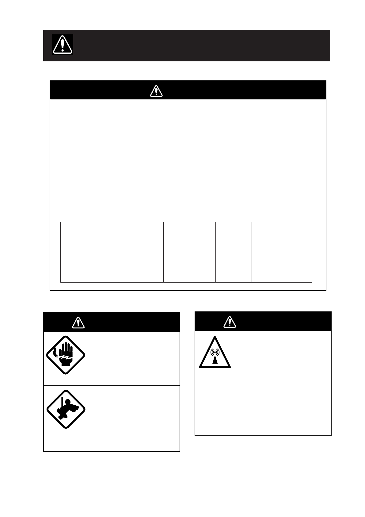
WARNING
Radio Frequency Radiation Hazard
The radar antenna emits electromagnetic radio frequency (RF) energy which can be
harmful, particularly to your eyes. Never look directly into the antenna aperture from a
close distance while the radar is in operation or expose yourself to the transmitting
antenna at a close distance.
2
Distances at which RF radiation levels of 100 and 10 W/m
below.
Note: If the antenna unit is installed at a close distance in front of the wheel house,
your administration may require halt of transmission within a certain sector of antenna
revolution. This is possible Ask your FURUNO representative or dealer to provide
this feature.
exist are given in the table
ledoM
V5212-RF
)Wk52,dnab-X(
rotaidaR
epyt
)'4(FA21NX
)'5.6FA02NX
)'8(FA42NX
WARNING
ELECTRICAL SHOCK HAZARD
Do not open the equipment.
Only qualified personnel
should work inside the
equipment.
Wear a safety belt and hard
hat when working on the
antenna unit.
Serious injury or death can
result if someone falls from
the radar antenna mast.
otecnatsiD
2
m/W001
tniop
esactsrowm1.1
otecnatsiD
2
m/W01
tniop
m0.01
esactsrow
ytisnedrewopFR
annetnano
erutarepa
2
mc/W002
WARNING
Turn off the radar power
switch before servicing the
antenna unit. Post a warning sign near the switch
indicating it should not be
turned on while the antenna
unit is being serviced.
Prevent the potential risk of
being struck by the rotating
antenna and exposure to
RF radiation hazard.
i
Page 4
WARNING
WARNING
Do not disassemble or modify the
equipment.
Fire, electrical shock or serious injury can
result.
Turn off the power immediately if water
leaks into the equipment or the equipment is emitting smoke or fire.
Continued use of the equipment can cause
fire or electrical shock.
Use the proper fuse.
Fuse rating is shown on the equipment.
Use of a wrong fuse can result in equipment damage.
Do not place liquid-filled containers on
the top of the equipment.
Fire or electrical shock can result if a liquid
spills into the equipment.
Do not operate the equipment with wet
hands.
Electrical shock can result.
Keep heater away from equipment.
Heat can alter equipment shape and melt
the power cord, which can cause fire or
electrical shock.
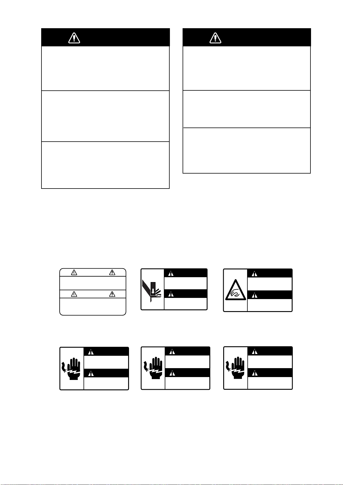
Danger/Warning Labels in Display Unit
This display unit contains the danger/warning labels shown below. Do not remove the
labels. If a label is peeling off or is illegible, contact a FURUNO agent for replacement.
WARNING
To avoid electrical shock, do not
remove cover. No user-serviceable
parts inside.
Name: Warning Label
Type: 86-003-1011
Code No.: 100-236-230
DANGER
Electrical shock hazard.
Do not touch parts inside
this cover.
Name: Warning Label
Type: 03-144-1332
Code No.: 100-266-290
WARNING
Display unit may fall.
Lock stay before
servicing.
DANGER
Electrical shock hazard.
Do not touch anode cap
or its cable.
WARNING
Possibility of injury.
Hold handle when
mounting display unit.
Name: Warning Label
Type: 03-144-1333
Code No.: 100-266-300
DANGER
Electrical shock hazard.
Turn off power before
servicing.
Name: Danger Label
Type: 14-055-4202
Code No.: 100-245-220
Name: Danger Label
Type: 14-055-4201
Code No.: 100-243-450
ii
Name: Danger Label
Type: 66-022-2012
Code No.: 100-237-730
Page 5
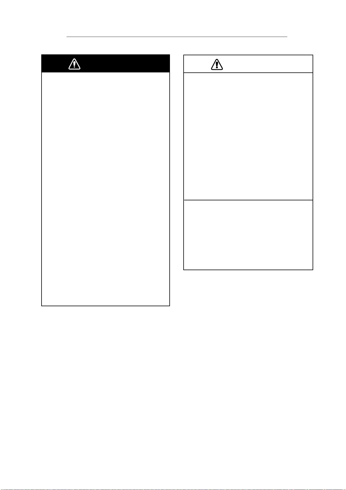
Safety Instructions for ARPA ARP-26 (Option)
WARNING
No one navigational aid should be relied
upon for the safety of vessel and crew.
The navigator has the responsibility to
check all aids available to confirm
position. Electronic aids are not
a substitute for basic navigational
principles and common sense.
• This auto plotter automatically tracks an
automatically or manually acquired radar
target and calculates its course and
speed, indicating them by a vector. Since
the data generated by the auto plotter
are based on what radar targets are
selected, the radar must always be
optimally tuned for use with the auto
plotter, to ensure required targets will not
be lost or unwanted targets such as sea
returns and noise will not be acquired
and tracked.
• A target does not always mean a land mass, reef, ships or other surface vessels
but can imply returns from sea surface
and clutter. As the level of clutter changes
with environment, the operator should
properly adjust the A/C SEA, A/C RAIN
and GAIN controls to be sure target
echoes are not eliminated from the
radar screen.
CAUTION
The plotting accuracy and response of
this auto plotter meets IMO standards.
Tracking accuracy is affected by the
following:
• Tracking accuracy is affected by course
change. One to two minutes is required to
restore vectors to full accuracy after an
abrupt course change. (The actual
amount depends on gyrocompass
specifications.)
• The amount of tracking delay is inversely
proportional to the relative speed of the
target. Delay is on the order of 15—30
seconds for high relative speed; 30—60
seconds for low relative speed.
Display accuracy is affected by the
following:
• Echo intensity
• Radar transmission pulsewidth
• Radar bearing error
• Gyrocompass error
• Course change (own ship or target)
iii
Page 6

Safety Instructions for VIDEO PLOTTER RP-26 (Option)
CAUTION
No one navigational aid should be relied
upon for the safety of vessel and
crew. The navigator has the responsibility to check all aids available to
confirm position. Electronic aids are not
a substitute for basic navigational
principles and common sense.
❐ Digital charts cannot replace official
nautical charts.
Digital charts are intended as an aid to
navigation. Position should always be
checked against nautical charts, as well
as other aids to navigation.
❐ Digital charts cannot replace the
radar.
Digital charts can only show own ship’s
position relative to a chart feature
(coastline, lighthouse, etc.). They cannot
show other vessels, as does the radar.
Digital charts can never replace the
radar.
❐ Handle chart/memory cards carefully.
• Keep cards away from heat sources.
• Keep cards away from magnets and
magnetic material.
• Replace cards in their protective cases
after use.
iv
Page 7

TABLE OF CONTENTS
INTRODUCTION ........................................................................................................ viii
SYSTEM CONFIGURATION...................................................................................ix
1. OPERATION
1.1 Turning on the Power................................................................................................ 1-1
1.2 Transmitter ON.......................................................................................................... 1-2
1.3 Control Head ............................................................................................................. 1-3
1.4 CRT Brilliance ........................................................................................................... 1-5
1.5 Tuning the Receiver .................................................................................................. 1-5
1.6 On-screen Legends and Markers.............................................................................. 1-6
1.7 Degaussing the CRT Screen..................................................................................... 1-7
1.8 Initializing the Gyro Readout ..................................................................................... 1-8
1.9 Entering Own Ship’s Speed ...................................................................................... 1-9
1.10 Presentation Modes ................................................................................................ 1-10
1.11 Selecting the Range Scale...................................................................................... 1-13
1.12 Selecting the Pulsewidth ......................................................................................... 1-13
1.13 Adjusting the Sensitivity .......................................................................................... 1-15
1.14 Suppressing Sea Clutter ......................................................................................... 1-15
1.15 Suppressing Precipitation Clutter............................................................................ 1-17
1.16 Interference Rejector............................................................................................... 1-17
1.17 Measuring the Range.............................................................................................. 1-18
1.18 Measuring the Bearing ............................................................................................ 1-20
1.19 Collision Assessment by Offset EBL ....................................................................... 1-21
1.20 Measuring Range and Bearing Between Two Targets ............................................ 1-22
1.21 Setting a Target Alarm Zone.................................................................................... 1-23
1.22 Off-Centering........................................................................................................... 1-25
1.23 Echo Stretch............................................................................................................ 1-25
1.24 Echo Averaging ....................................................................................................... 1-26
1.25 Electronic Plotting Aid (EPA) ................................................................................... 1-28
1.26 Target Trails............................................................................................................. 1-32
1.27 Parallel Index Lines................................................................................................. 1-34
1.28 Origin Mark.............................................................................................................. 1-36
1.29 Zoom ....................................................................................................................... 1-37
1.30 Markers ................................................................................................................... 1-37
1.31 Menu Keys .............................................................................................................. 1-38
1.32 RADAR 1, 2 and 3 Menu Settings........................................................................... 1-39
1.33 Function Keys ......................................................................................................... 1-40
1.34 Barge Information.................................................................................................... 1-46
1.35 Radar Map .............................................................................................................. 1-46
1.36 Suppressing Second-trace Echoes......................................................................... 1-50
1.37 Displaying External Waypoint and Navigation Line................................................. 1-50
1.38 Adjusting Brilliance of Screen Data......................................................................... 1-51
1.39 Display of Wind/Tide/Depth/Time ............................................................................ 1-52
1.40 Rate-of-Turn Scale.................................................................................................. 1-53
1.41 Alarms ..................................................................................................................... 1-54
v
Page 8

2. RADAR OBSERVATION
2.1 General ..................................................................................................................... 2-1
2.2 False Echoes ............................................................................................................ 2-3
2.3 SART (Search and Rescue Transponder) ................................................................ 2-5
2.4 RACON (Radar Beacon)........................................................................................... 2-7
3. MAINTENANCE
3.1 Periodic Maintenance Schedule................................................................................ 3-2
3.2 Life Expectancy of Major Parts ................................................................................. 3-2
3.3 Replacement of Battery............................................................................................. 3-3
4. TROUBLESHOOTING
4.1 Easy Troubleshooting................................................................................................ 4-2
4.2 Advanced-level Troubleshooting............................................................................... 4-2
4.3 Diagnostic Test.......................................................................................................... 4-4
5. ARPA ARP-26 (Option for NM-type radar)
5.1 General ..................................................................................................................... 5-1
5.2 Controls for ARPA ..................................................................................................... 5-2
5.3 ARPA Menu Operation .............................................................................................. 5-2
5.4 Start-up Procedure.................................................................................................... 5-4
5.5 Automatic Acquisition ................................................................................................ 5-6
5.6 Manual Acquisition .................................................................................................... 5-9
5.7 Changing Plot Symbol Size, Plot Symbols.............................................................. 5-10
5.8 Adjusting Brilliance of Plot Marks............................................................................ 5-12
5.9 Displaying Target Data ............................................................................................ 5-13
5.10 Vector Modes .......................................................................................................... 5-14
5.11 Past Position Display .............................................................................................. 5-15
5.12 Set and Drift (Set and Rate).................................................................................... 5-16
5.13 Setting CPA/TCPA Alarm Ranges ........................................................................... 5-17
5.14 Setting a Guard Zone.............................................................................................. 5-18
5.15 Operational Warnings.............................................................................................. 5-20
5.16 Trial Maneuver ........................................................................................................ 5-21
5.17 ARPA Performance Test.......................................................................................... 5-24
5.18 Criteria for Selecting Targets for Tracking ............................................................... 5-25
5.19 Factors Affecting ARP A Functions........................................................................... 5-26
6. VIDEO PLOTTER RP-26 (Option for NM-type radar)
6.1 General ..................................................................................................................... 6-1
6.2 The Video Plotter Display.......................................................................................... 6-2
6.3 Display Modes........................................................................................................... 6-2
6.4 Set-up of Video Plotter Display ................................................................................. 6-4
6.5 Track ......................................................................................................................... 6-6
6.6 Marks, Lines.............................................................................................................. 6-8
6.7 Waypoints.................................................................................................................6-11
6.8 Navigation Lines...................................................................................................... 6-13
6.9 Recording, Replaying Data ..................................................................................... 6-16
6.10 Initial Settings.......................................................................................................... 6-17
vi
Page 9

APPENDIX
Menu Tree..........................................................................................................................A-1
Set-up for Fishing Vessel ...................................................................................................A-6
SPECIFICATIONS ..................................................................................................SP-1
INDEX
vii
Page 10

INTRODUCTION
A Word to the Owner of FURUNO Radar
Thank you for purchasing this FURUNO radar. We are confident you will discover why
FURUNO has become synonymous with quality and reliability.
Dedicated in the design and manufacture of marine electronics equipment for more than
half a century , FURUNO Electric Company has gained an unrivaled reputation as a world
leader in the industry. This is the result of our technical excellence as well as our worldwide distribution and service network.
Please carefully read and follow the safety information and operating and maintenance
instructions set forth in this manual before attempting to operate the equipment and conduct any maintenance. Your radar set will perform to the utmost of its ability only if it is
operated and maintained in accordance with the correct procedures.
Features of this Series of Radars
• Daylight-bright rasterscan 21-inch multi-color, high-resolution display
• New microprocessing technology with high-speed high-density gate array and software
expertise
• New cast aluminum scanner gearbox and new series of radiators
• Easy operation by combination of discrete keys, rotary controls, and menu operation,
all logically arranged and configured.
• Electronic Plotting Aid (EPA) fitted standard.
• Reliable CPA and TCPA warning in any plotting mode, accurate target data.
• Stand-alone or integrated configuration
• A Video Plotter (Chart Plotter) is also optionally available.
viii
Page 11
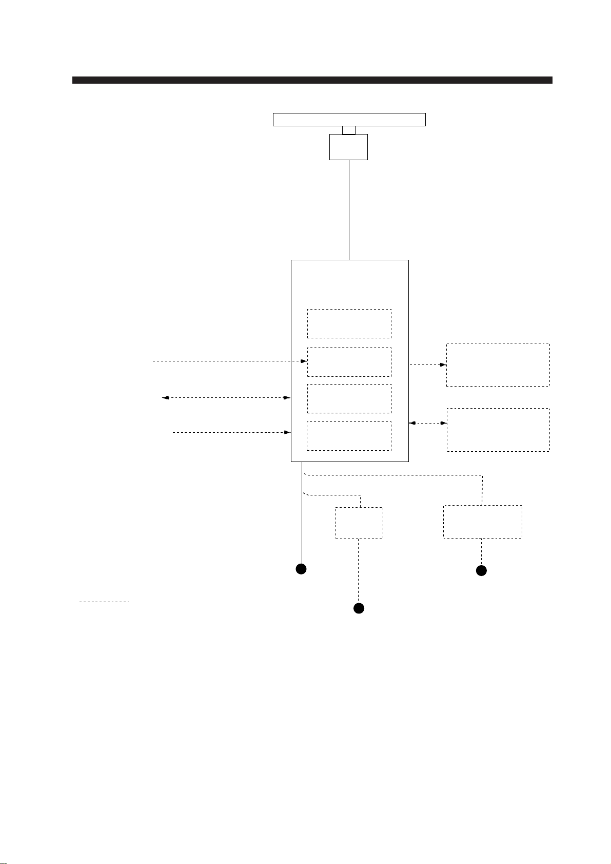
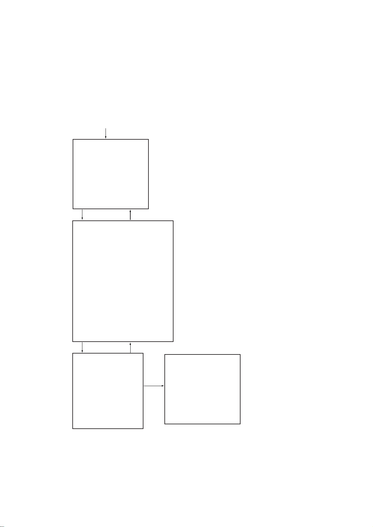
SYSTEM CONFIGURATION
XN12AF-RSB-0074-063
XN12AF-RSB-0075-063
XN20AF-RSB-0074-063
XN20AF-RSB-0075-063
XN24AF-RSB-0074-063
XN24AF-RSB-0075-063
DISPLAY UNIT
ANTENNA UNIT
RDP-126
ARPA
ARP-26*
Gyrocompass
Navigator
Speed Log
Option
IEC-61162-1 Serial Data
(Input/Output)
IEC-61162-1 Serial Data
(Input)
* Not available for statute
mile-(SM) type radar.
Ship's Mains
24-32 VDC
or
100-115/220-230 VAC
1, 50/60 Hz
Gyro Converter
GC-8
Video Plotter
RP-26*
Alarm Kit
DC spec
Rectifier
RU-3424
Slave Display
FMD-8010
Performance
Monitor
PM-30
AC spec
Transformer Unit
RU-1803
440 VAC
1, 50/60 Hz
AC spec or DC spec to be selected.
ix
Page 12
1. OPERATION
1.1 Turning on the Power
DANGER
Before turning on the radar, make sure
no one is near the antenna unit.
Serious injury or death may result if a
rotating antenna strikes someone standing
nearby.
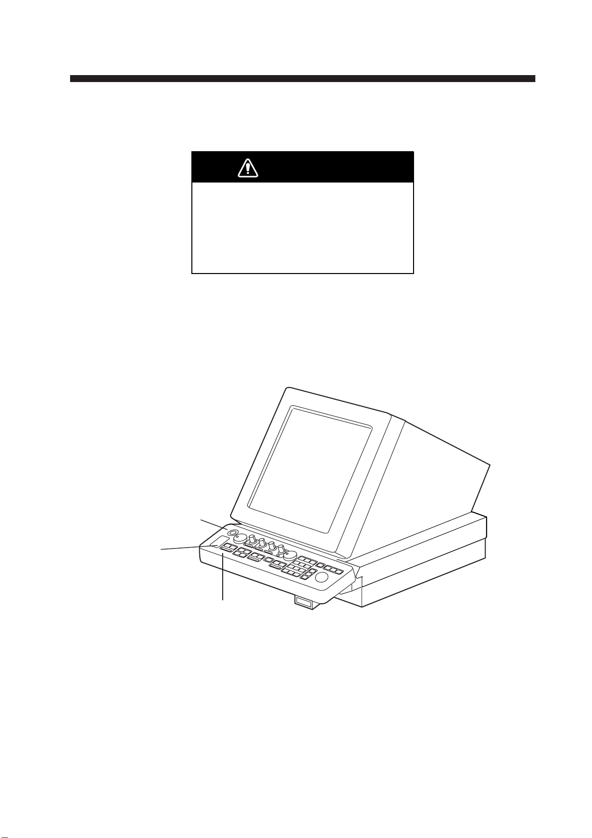
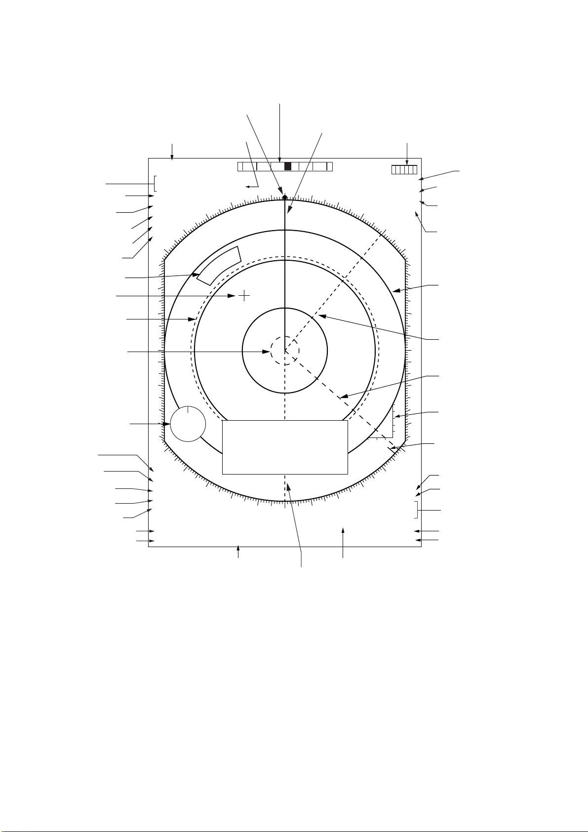
The [POWER] switch is located at the left corner of the control head. Push it to switch on
the radar system. To turn off the radar, push it again. The screen shows the bearing scale
and digital timer in approximately 15 seconds after power-on. The timer counts down
three minutes of warm-up time. During this period the magnetron, i.e., transmitter tube, is
warmed for transmission. When the timer has reached 0:00, the indication STBY appears,
indicating the radar is now ready to transmit pulses.
POWER switch
Tuning
Compartment
Control Head
Figure 1-1 Display unit
Note: Allow 10 seconds to elapse before turning off the power, to permit writing of
settings.
In warm-up and standby condition, you will see the message BRG SIG MISSING. This is
normal because a bearing (azimuth) signal is not yet generated when the antenna is not
rotating. ON TIME and TX TIME values shown at the bottom of the screen are the time
counts in hours and tenths of hour the radar has been powered.
1-1
Page 13
1.2 Transmitter ON
When the STANDBY status is displayed on the screen, press the transmit switch labeled
STBY/TX on the control head of the display unit.
The radar is initially set to previously used range and pulsewidth. Other settings such as
brilliance levels, VRMs, EBLs and menu option selections are also set to previous settings.
The transmit switch toggles the radar between STANDBY and TRANSMIT status. The
antenna stops in STANDBY status and rotates in TRANSMIT status.
If the antenna does not rotate in TRANSMIT status, check whether the antenna switch in
the tuning compartment is in the OFF position.
The magnetron ages with time resulting in a reduction of output power . It is highly recommended that the radar be set to ST ANDBY status when not used for an extended period of
time.
Note: The example screens shown in this manual may not match the screens you see on
your display. The screen you see depends on your system configuration and equipment
settings.
Quick start
Provided that the radar was once in use with the transmitter tube (magnetron) still warm,
you can turn the radar into TRANSMIT condition without 3-minutes standby . If the [POWER]
switch has been turned off by mistake or the like and you wish to restart the radar promptly ,
turn on the switch not later than 10 seconds after power-off.
Video Freeze-up Recovery
Video freeze-up or lock-up can occur unexpectedly on any digital rasterscan radars.
This is mainly caused by heavy spike noise
in the power line and can be noticed by
carefully watching the nearly visible sweep
line. If you suspect that the picture is not
updated every scan of the antenna or no
key entry is accepted notwithstanding the
apparently normal pictures, do Quick Start
to restore normal operation.
1. Turn off the [POWER] switch and within
10 seconds turn it on again.
2. Press the Transmit switch labeled
STBY/TX for transmit condition.
1-2
Note: This equipment has a self-diagnostic
function to check operational software
periodically. If any trouble has been found,
the ERROR lamp lights. In this case, do the
above procedure.
Page 14
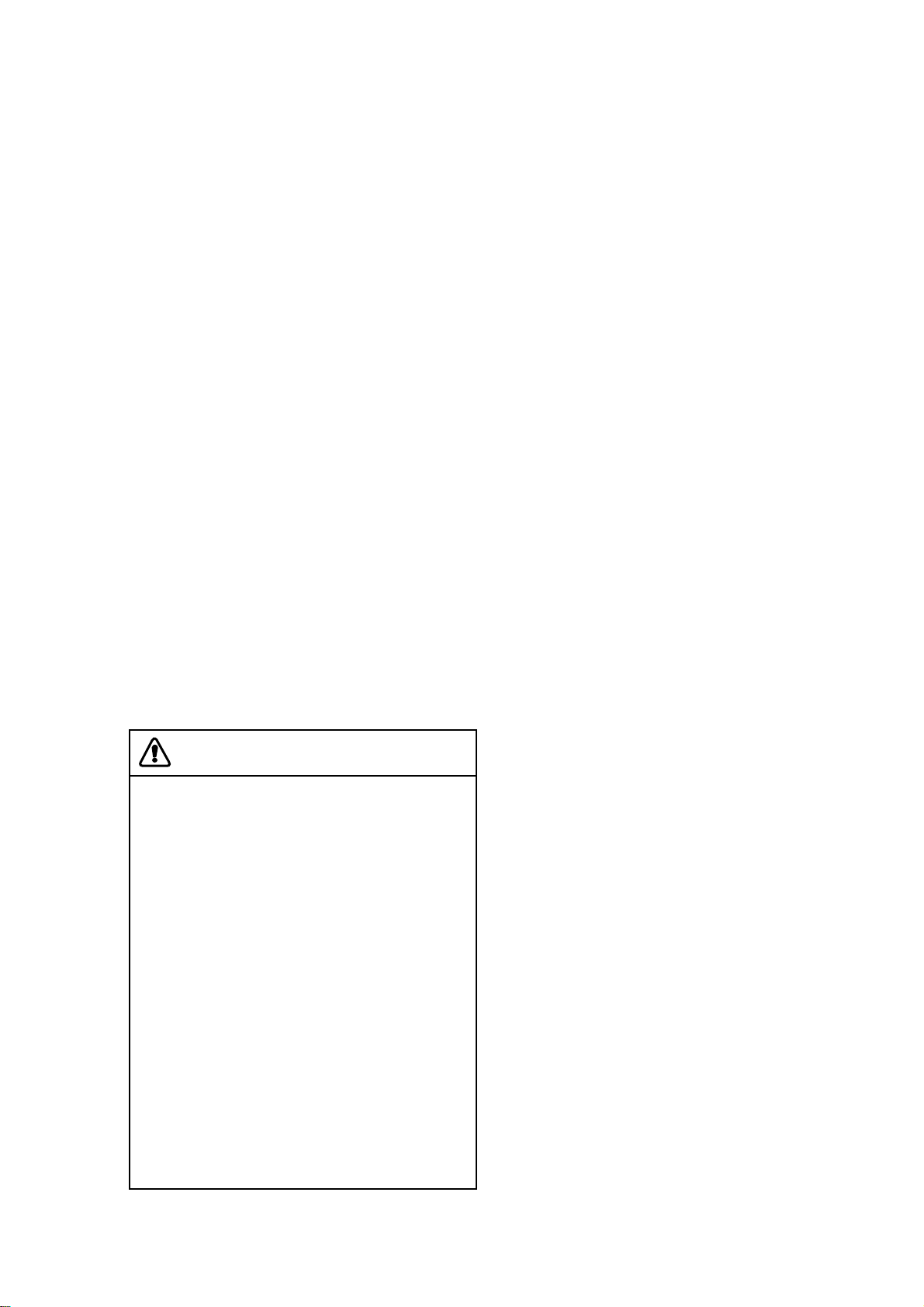
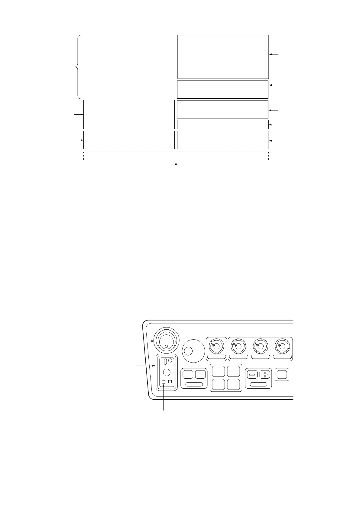
1.3 Control Head
A/C RAIN
Suppresses clutter from
rain, snow, clouds.
BRILLIANCE
Adjusts the brightness
of entire screen.
A/C SEA
Suppresses sea clutter to
improve the short range
discrimination.
AUDIO OFF
Acknowledges audible alarms, no effect on
visual alarms.
RADAR MENU
Sets various parameters for
radar operation and radar map.
GAIN
Adjusts the radar sensitivity.
NAV MENU
Sets parameters for nav info.
PLOT MENU
for plotting
POWER
ON
OFF
PM
ANTENNA
TUNE
DEGAUSS ERROR
OFF ON
EBL
EBL Control,
EBL ON/OFF Keys
Pressing ON key toggles
between No.1 and No.2
EBLs.
FUNCTION Keys
#1: Set-up 1
#2: Set-up 2
#3: Set-up 3
#4: Set-up 4
BRILLIANCE A/C RAIN A/C SEA GAIN
#1 #2
#3 #4
RANGE
STBY
TX
TRANSMIT/STANDBY
RANGE Keys
Select the range scales.
Figure 1-2 Control head
HL
PANEL
MODE
BRILL
2
1
4
7
VECTOR
CHART
ALIGN
CU, TM
RESET
LOST
TARGET
5
MARK
8
A/C
AUTO
0
ENTER
OFF ON
VRM
OFF
OFF
CENTER
EBL
TARGET
TRAILS
CANCEL
VRM Control,
VRM ON/OFF Keys
Pressing ON key toggles
between No.1 and No.2
VRMs.
AUDIO
RADAR
PLOT
OFF
ACQ
TARGET
DATA
TARGET
CANCEL
MENU
3
6
9
MENU
NAV
MENU
TRACKBALL
Shifts the cursor for plotting,
entering reference points,
etc.
1-3
Page 15
(3) (2) (1)
(12)
(4)
(5)
HL
OFF
OFF
CENTER
EBL
OFFSET
TARGET
TRAILS
CANCEL
(1 1) (6)
1
4
7
PANEL
BRILL
2
VECTOR
5
CHART
ALIGN
8
CU, TM
RESET
0
(14)
MODE
LOST
TARGET
MARK
A/C
AUTO
ENTER
(7),
AUDIO
3
OFF
RADAR
MENU
PLOT
MENU
NAV
MENU
(13)
6
ACQ
9
TARGET
DATA
TARGET
CANCEL
(8)
(9)
(10)
(15)
(16)
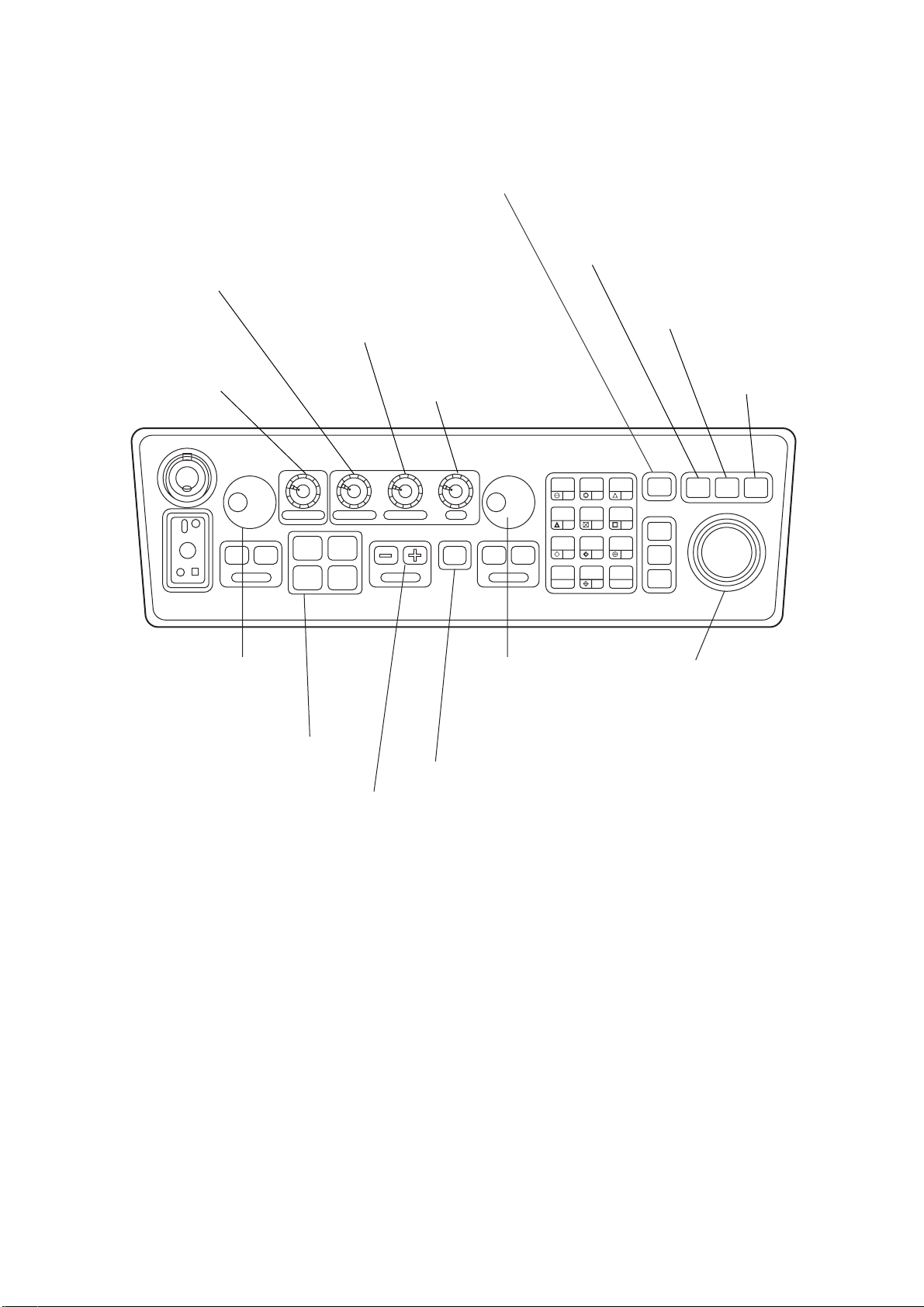
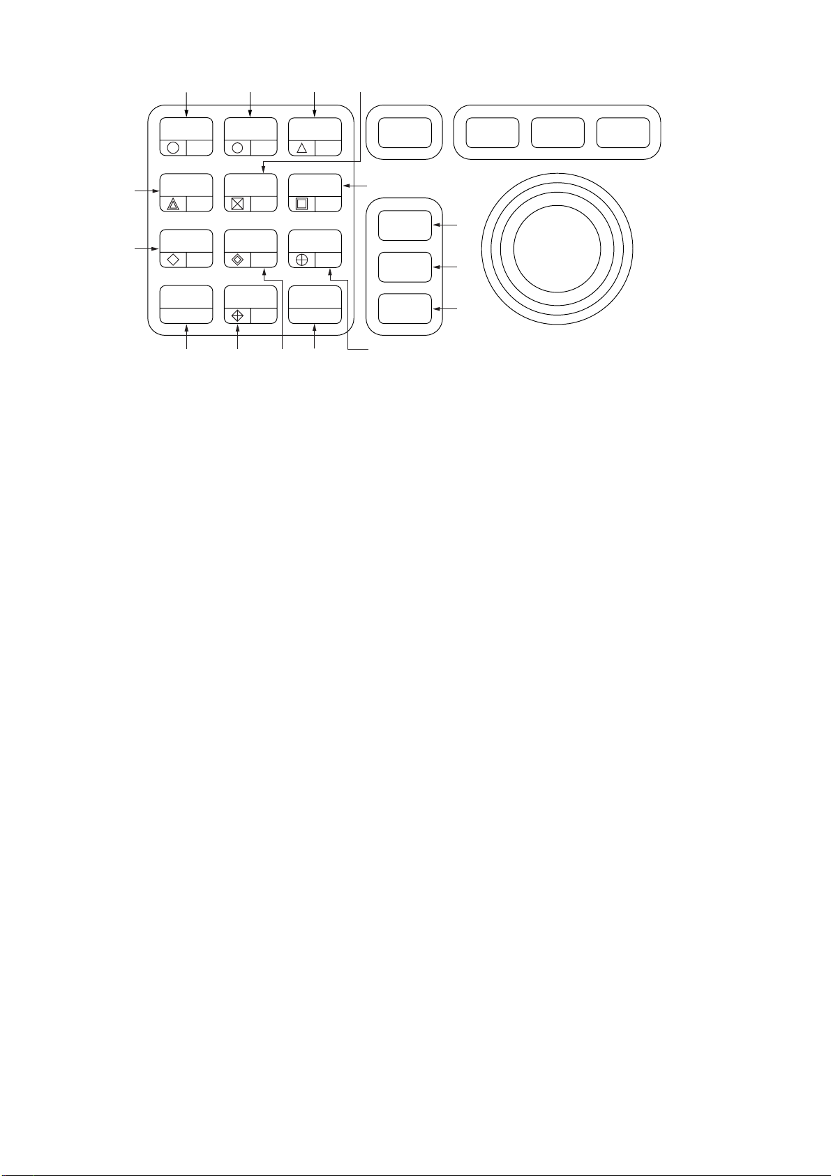
Figure 1-3 Control head, key panel
(1) MODE: Selects presentation modes: Head-up, Head-up TB, North-up, Course-up and
True Motion.
(2) PANEL BRILL: Adjusts brightness of the control head panel.
(3) HL OFF: Temporarily erases the heading line.
(4) OFF-CENTER: Activates and deactivates off-centering of the own ship position.
(5) EBL OFFSET: Activates and deactivates off-centering of the EBL origin.
(6) CU, TM RESET: Resets the heading line to 000° in course-up mode; moves own ship
position to 50% (75% for NM-type radar) radius in stern direction in the T rue Motion mode.
(7) A/C AUTO: Reduces sea clutter at preset level. Permits manual override by A/C SEA
and A/C RAIN controls.
(11) TARGET TRAILS/CANCEL: Erases target trails.
Keys for EPA or ARPA (optional)
(8) ACQ: Acquires a target after selecting it by trackball.
(9) TARGET DATA: Displays acquired target data.
(10) TARGET CANCEL: Terminates plotting of a specified target or all tracked targets.
(12) VECTOR: Selects vector mode; true or relative.
(13) LOST TARGET: Silences the lost target audible alarm and erases the lost target
symbol.
(14) CHART ALIGN: Aligns chart with the radar display. Used with radar map/video plot-
ter.
(15) MARK: Enters/erases mark. Used with radar map/video plotter.
(16) ENTER: Used to save settings on menu screen.
Keys 0-9: Select video plotting symbols. Also used for entering numeric data in any mode
as applicable.
1-4
Page 16

1.4 CRT Brilliance
The [BRILLIANCE] control on the control head of the display unit adjusts the entire screen
brightness. Note that the optimum point of adjustment varies with ambient light conditions,
especially between daytime and nighttime.
Note: The CRT brilliance should be adjusted before adjusting relative brilliance levels on
the BRILLIANCE menus to be explained later.
1.5 Tuning the Receiver
Tuning method can be selected at the RADAR 3 menu; auto or manual.
1. Press the [RADAR MENU] key.
2. Press [0], [0], [2], [0] and [0] in sequence to display the RADAR 3 menu.
3. Press the [9] key twice to select AUTO or MAN(ual).
4. Press the [ENTER] key to confirm your selection.
5. Press the [RADAR MENU] key to close the menu.
1.5.1 Automatic tuning
The radar receiver is tuned automatically each time the power is turned on; thus, there is
no front panel control for tuning. The tuning indicator and the label AUTO TUNE at the top
right corner of the display unit show the tuning circuit is working.
1.5.2 Manual tuning
If you are not satisfied with the current tune setting, follow these steps to fine-tune the
receiver:
1. Set the tuning method to manual as described above.
2. While observing the picture on the 48 mile scale, slowly adjust the [TUNE] control in
the tuning compartment and find the best tuning point.
[TUNE] control
Figure 1-4 Control head, showing tuning compartment
3. Make sure that the radar has been set to the best tuning point. This condition is where
the tuning indicator lights to about 80% of its total length. Note that the tuning indicator
will never extend to full length.
ERROR lamp
1-5
Page 17
1.6 On-screen Legends and Markers
Rate-of-Turn Scale
Heading Marker
Range/Range
Ring Interval
Range and bearing
to cursor
Presentation
mode
Pulselength
Echo Averaging
Interference Rej.
Echo Stretch
Guard Alarm
Cursor
No.1 VRM
No.2 VRM
Wind data from
ext. equipment
Zoom
X-band
A/C AUTO
Noise Rej.
Off-center
No.1 EBL bearing
No.2 EBL bearing
0.75
/0.25SM
+0.350SM
330.0° T
HEAD UP RM
PULSE 1 M1
EAV3
IR1
320
ES3
310
300
290
280
270
260
250
240
230
220
ZOOM
X-BAND
A/C AUTO
NOISE REJ
OFFCENTER
EBL
044.4° T
>130.1° T<
2nd Trace
Echo Rejector
P
2ND ECHO
340
330
WS
NE
210
200
INDEX
>236.8° T<
0° 30° 60° 90°30°60°90°
000
350
010
DATA DISPLAY
(See next page.)
190
180
170
Heading Line
SB
AUTO TUNE
/MIN
WATCH 5 : 30
HDG 123.4°T GYRO
SPEED 14.8KT WT LOG
020
030
150
160
TGT ALARM 1
TGT ALARM 2
Tuning Bar
ANT1 MAIN
SET & DRIFT
040
050
0
20
40
60
80
100
m
10MIN
20-30
130
140
TRUE TRAIL
3MIN 1:25
VRM
>0.600SM<
0.150SM
060
070
080
090
100
110
120
Heading
Speed Source,
Speed
Antenna,
Display in use
Set & Drift
Fixed Range
Rings
No.1 EBL
No.2 EBL
Depth data from
ext. equipment
North Marker
Target Trail
Trail Time/
Time Elapsed
Target Alarm
No.1 VRM range
No.2 VRM range
Parallel Index
Lines Orientation
Stern Marker
Watch
Figure 1-5 On-screen legends and markers
Note: With the serial speed inputs and SOG selection, if the type of data is changed from
SOG to STW, the label SOG appears in red at the upper right corner on the screen.
1-6
Page 18
EPA
Target
Data
01
RNG
BRG
CSE
SPD
CPA
TCPA
BCR
BCT>
0 : 03
0.439SM
122.7°T
254.2°T BT TRU
14.9KT BT TRU
0.4SM
0.0MIN
0.8SM
99.9MIN
DEPTH
CURRENT
WIND
01 − > +
21.1m
1.2KT
105.7°T
11.3KT
285.6°T
0.101SM
254.3°T
Nav Data
Range and bearing
from origin mark to
cursor
EPA Setting
Position
EPA
TRUE VECTOR 6MIN BT
OWN SHIP [GP]
MAN
34°57.843N
135°57.720E
WPT 12
1999/03/03 13:28 UTC
+CURSOR POSN
MAN
150.8SM
72.1°T
34°57.692N
134°57.597E
Range and Bearing
to Waypoint*
Date, Time
Cursor Position
* Nav data displayed when no
Alarm Message
waypoint is selected.
Area
Figure 1-6 Data display
1.7 Degaussing the CRT Screen
Each time the radar is turned on, the degaussing circuit automatically demagnetizes the
CRT screen to eliminate color contamination caused by earth’ s magnetism or magnetized
ship structure.
The screen is also degaussed automatically at certain time intervals. While being degaussed, the screen may be disturbed momentarily with vertical lines. If you wish to degauss by manual operation, open the tuning compartment and press the [DEGAUSS]
switch.
[POWER] switch
Tuning compartment
POWER
ON
PM
ANTENNA
TUNE
DEGAUSS ERR
OFF ON
EBL
[DEGAUSS] switch
BRILLIANCE A/C RAIN A/C SEA GAIN
#1 #2
#3 #4
RANGE
STBY
TX
Figure 1-7 Control head, showing tuning compartment
1-7
Page 19

1.8 Initializing the Gyro Readout
When a gyrocompass is interfaced with the radar, ship’s heading is displayed at the top
right-hand corner of the screen. Upon turning on the radar, align the on-screen HDG readout with the gyrocompass reading by the procedure shown below. Once you have set the
initial heading correctly, resetting is not usually required. However, if the HDG readout
goes wrong for some reason, repeat the procedure to correct it.
1. Press the [RADAR MENU] key to display the FUNCTIONS 1 menu.
[FUNCTIONS (1)]
1 TARGET TRAILS
2 TARGET ALARM (1 or 2)
3 ORIGIN MARK (1 to 10)
4 INDEX LINES
5 ZOOM
6 PULSE WIDTH
7 INT REJECT
8 ARPA
9 VIDEO PLOT
0 [FUNCTIONS (2)]
Figure 1-8 FUNCTIONS 1 menu
2. Press the [0] key twice to display the FUNCTIONS 3 menu.
[FUNCTIONS (3)]
1 [FUNCTIONS (2)]
2 [RADAR (1)]
3 [FUNCTION KEY 1]
4 [FUNCTION KEY 2]
5 [FUNCTION KEY 3]
6 [FUNCTION KEY 4]
7 RADAR 1/2
8 INTER SWITCH
9 GYRO SETTING
0 [FUNCTIONS (4)]
Figure 1-9 FUNCTIONS 3 menu
3. Press the [9] key to select the option GYRO SETTING.
4. Rotate the EBL control to adjust the gyrocompass (heading) reading.
5. Press the [ENTER] key to confirm the setting.
1-8
Page 20

1.9 Entering Own Ship’ s Speed
EPA and any azimuth stabilized presentation modes require speed input and gyrocompass signal. The speed can be entered from a speed log (automatic) or through the plotting keypad (manual).
1.9.1 Automatic speed input
1. Press the [RADAR MENU] key and the [0] key to show the FUNCTIONS 2 menu.
[FUNCTIONS (2)]
1 [FUNCTIONS (1)]
2 BKGD COLOR BLK(GRN CHAR)/
BLK(RED CHAR)/
BLU (ECHO AREA)
BLU/
BRT BLU
3 ECHO STRETCH OFF/1/2/3
4 ECHO AVERAGE OFF/1/2/3
5 ECHO COLOR YEL/GRN/COLOR
6 SHIP SPEED LOG/NAV/MAN
MAN = 00.0KT
(STW/SOG)
7 SET, DRIFT OFF/MAN
SET = 000.0°
DRIFT = 00.0KT
8 INDEX LINES NO. 2 VRM/MAN
MAN = 00.00SM
9 [BRILLIANCE (1)]
0 [FUNCTIONS (3)]
SOG (Speed-over-the-ground) is the Speed Made Good
over the ground determined by EPFS, Echo Reference or
Dual-axis speed log. It is obtained by a distance between
points over the ground divided by the time spent for
traveling between these two points.
Figure 1-10 FUNCTIONS 2 menu
2. Press the [6] key to select menu item 6 SHIP SPEED.
3. Press the [6] key to select LOG or NAV.
4. When the serial speed data is selected at the installation menu, select the speed mode,
STW (speed through the water) or SOG (speed over the ground). If pulse speed data
is selected, the STB/SOG does not appear.
5. Press the [ENTER] key to confirm your selection followed by the [RADAR MENU] key
to close the FUNCTIONS menu. The ship’s speed readout at the screen top shows
own ship’s speed fed from the speed log followed by the label “LOG.”
Notes on automatic speed input
1) IMO Resolution A.823(19) for ARP A recommends that a speed log to be interfaced with
an ARPA should be capable of providing through-the-water speed.
2) Be sure not to select LOG when a speed log is not connected. If the log signal is not
provided, the ship’s speed readout at the top right-hand corner will be blank.
3) SPD **.* and SIGNAL MISSING LOG appears if no log signal is present for 30 seconds
while the ship’s speed has been more than 5.0 kt.
4) With the serial speed inputs and SOG selection, if the type of data is changed from
SOG to STW, the label SOG appears in red at the upper right corner on the screen.
1-9
Page 21

1.9.2 Manual speed input
1. Press [RADAR MENU], [0] to show the FUNCTIONS 2 menu.
2. Press the [6] key to select menu 6 SHIP SPEED.
3. Press the [6] key to select (or highlight) MAN.
4. Press the [ENTER] key to confirm selection. At this point, “MAN = 00.0KT” appears on
the FUNCTIONS 2 menu.
5. Enter the ship speed by hitting corresponding numeric keys followed by the [ENTER]
key without omitting leading zeros, if any. For example, if the ship speed is 8 knots,
press [0], [8], [ENTER].
6. Press the [RADAR MENU] key to close the FUNCTIONS 2 menu. The ship speed
readout at the top right-hand corner shows own ship speed entered followed by the
label “MAN.”
1.10 Presentation Modes
This radar has the following presentation modes:
Relative Motion (RM)
Head-up: Unstabilised
Head-up TB: Head-up with gyrocompass-stabilized bearing scale (True Bearing) where
the bearing scale rotates with the gyrocompass reading.
Course-up: Gyrocompass-stabilized relative to ship’s intended course
North-up: Gyrocompass-stabilized with reference to north
True Motion (TM)
North-up: Ground or sea stabilized with gyrocompass and speed inputs
1.10.1 Selecting presentation mode
Press the [MODE] key on the control head. Each time the [MODE] key is pressed, the
presentation mode and mode indication at the upper left-hand corner of the screen change
cyclically .
Loss of Gyrocompass SignalLoss of Gyrocompass Signal
When the gyro compass signal is lost, the
presentation mode automatically becomes
head-up and the HDG (heading) readout at
the top right-hand corner shows ***.*.
When the gyrocompass signal is restored,
the indication SET HDG appears at the
upper-right corner on the screen. Press the
[MODE] key, and the asterisks go off. Align
the HDG readout with the gyrocompass
reading, referring to the paragraph 1.8.
Finally, press the CANCEL key to erase the
message SET HDG.
HL
OFF
OFF
CENTER
EBL
TARGET
TRAILS
CANCEL
PANEL
BRILL
1
VECTOR
4
CHART
ALIGN
7
CU, TM
RESET
[MODE] key
MODE
AUDIO
LOST
MARK
A/C
AUTO
OFF
3
6
ACQ
TARGET
9
DATA
TARGET
CANCEL
2
TARGET
5
8
0
ENTER
RADAR
MENU
PLOT
MENU
NAV
MENU
1-10
Figure 1-11 Control head, key panel
Page 22
Presentation mode,
representative display
H
E
A
D
U
P
280
270
260
300
290
250
North
Marker
310
240
230
000
350
340
330
320
220
210
200
190
180
Heading
Marker
010
020
030
150
160
170
Heading
Line
040
050
130
140
Description
A display without azimuth stabilization in which the
line connecting the center with the top of the display
indicates own ship’s heading.
060
120
The target pips are painted at their measured distances and in their directions relative to own ship’s
070
heading.
080
090
A short line on the bearing scale is the north marker
100
indicating gyrocompass north. A failure of the gyro-
110
compass input will cause the north marker to disappear and the readout to show asterisks (***.*).
Radar echoes are shown in the same way as in the
head-up mode. The difference from normal head-up
presentation lies in the orientation of the bearing
scale. The bearing scale is gyrocompass stabilized.
That is, it rotates in accordance with the gyrocompass signal, enabling you to know own ship’s
310
heading at a glance.
320
330
This mode is available only when the radar is interfaced with a gyrocompass.
340
350
If the gyrocompass fails, the bearing scale returns to
the state of head-up mode.
230
070
240
060
Heading
Marker
250
260
270
030
040
050
Heading
Line
280
290
010
020
300
000
H
E
A
D
190
180
U
P
170
160
T
150
R
140
U
130
E
120
B
110
E
A
200
100
210
090
220
080
R
I
N
Bearing scale rotates with
gyrocompass signal.
G
Heading
Marker
280
270
260
300
290
250
240
North
Marker
320
310
230
220
000
010
350
340
330
210
200
190
020
160
170
180
C
O
U
R
S
E
U
P
030
150
Heading
Line
040
050
130
140
060
070
080
100
110
120
An azimuth stabilized display in which a line connecting the center with the top of the display indicates
own ship’s intended course (namely, own ship’s
previous heading just before this mode has been
selected).
Target pips are painted at their measured distances
and in their directions relative to the intended course
090
which is maintained at the 0-degree position while the
heading line moves in accordance with ship’s yawing
and course change. This mode is useful to avoid
smearing of picture during course change. After a
course change, press the [CU, TM RESET] key to
reset the picture orientation if you wish to continue
using the course-up mode. The heading line gets
back to scale zero.
1-11
Page 23
Presentation mode,
representative display
North
000
350
340
200
190
180
North
000
350
340
200
190
180
M
N
O
R
T
H
290
280
U
270
P
260
250
330
320
310
300
240
230
220
210
T
R
U
E
290
280
O
270
T
260
I
250
O
N
330
320
310
300
240
230
220
210
Heading Line
010
020
160
170
Heading Line
010
020
030
150
160
170
030
150
040
050
130
140
Heading
Marker
040
050
130
140
Heading
Marker
060
070
080
090
100
110
120
060
070
080
090
100
110
120
Description
In the north-up mode, target pips are painted at their
measured distances and in their true (compass)
directions from own ship, north bearing maintained up
of the screen. The heading line changes its direction
according to the ship’s heading.
If the gyrocompass fails, the presentation mode
changes to head-up and the north marker disappears.
Also, the HDG readout shows asterisks (***.*).
Own ship and other moving objects move in accordance with their true courses and speed. In ground
stabilized TM, all fixed targets, such as landmasses,
appear as stationary echoes. In the sea stabilized TM
without set and drift inputs, the landmass can move on
the screen.
When own ship reaches a point corresponding to 50%*
of the radius of the display, it is automatically reset to a
point of 50%* radius opposite to the extension of the
heading line passing through the display center.
Resetting can be made at any moment before the ship
reaches the limit by pressing the [CU, TM RESET] key.
Automatic resetting is preceded by a beep sound.
If the gyrocompass fails, the mode is changed to the
head-up and the north marker disappears. The HDG
readout shows asterisks (***.*).
000 010
350
340
330
320
310
300
290
280
270
260
250
240
230
220
210
200
020
030
040
050
060
070
080
090
100
110
120
130
140
150
160
170180190
320
310
300
290
280
270
260
250
240
230
220
000 010
350
170180190
020
030
150
160
Target trail
040
050
060
070
080
090
100
110
120
130
140
320
310
300
290
280
270
260
250
240
230
220
340
330
210
200
000 010
350
340
330
210
200
020
030
150
160
170180190
(a) True motion selected (b) Own ship has reached a (c) Own ship is automatically
point 50%* of display radius reset to 50%* of radius
* 75% in case of NM-type radar.
040
050
060
070
080
090
100
110
120
130
140
1-12
Page 24

1.11 Selecting the Range Scale
The display range scale is changed by pressing the [+] and [-] keys. The selected range
scale and range ring interval are shown at the upper left corner on the screen. When a
target of interest comes closer, reduce the range scale so that it appears in 50–90% of the
display radius. The range scales are:
0.25–0.5–0.75–1–1.5–2–3–4–6–8–12–16–24–32–48–96 SM
1.12 Selecting the Pulsewidth
The pulsewidth in use is displayed at the upper left-hand position of the screen using the
abbreviations shown in the table below.
Appropriate pulsewidths are preset to individual range scales and function keys. Therefore, you are not usually required to select them. If you are not satisfied with the current
pulsewidth settings, however, it is possible to change them on the RADAR 1 menu as
shown in paragraph 1.12.2.
You can choose the pulsewidth 1 or 2 on the scales 0.5 to 24 SM ranges.
1.12.1 Selecting pulsewidth 1 or 2
1. Press the [RADAR MENU] key to display the FUNCTIONS 1 menu.
2. Press the [6] key to select PULSE WIDTH 1 or 2 as appropriate.
3. Press the [RADAR MENU] key to close the FUNCTIONS 1 menu.
Table 1-1 Available pulsewidths
lebaLhtdiwesluP
)1esluptrohS(1Ssµ70.0
)2esluptrohS(2Ssµ51.0
)1eslupmuideM(1Msµ3.0
)2eslupmuideM(2Msµ5.0
)3eslupmuideM(3Msµ7.0
)eslupgnoL(Lsµ2.1
1.12.2 Presetting pulsewidth 1 and 2
Pulsewidth 1 and 2 can be preset on the PULSE WD 1 and 2 menus. Shown below are
examples of the pulsewidth setup procedure.
1. To enable selection of S1 (0.07 µs) and S2 (0.15 µs) pulsewidth on the 0.5 SM range,
select S1 at 0.5 SM on the PULSE WD 1 menu and S2 at 0.5 SM on the PULSEWIDTH
2 menu.
1-13
Page 25
2. To enable selection of S2 (0.15 ms) and M1 (0.3 ms) pulsewidth on the 3 SM range,
select S2 at 3 SM in the PULSE WD 1 menu and M1 at 3 SM in the PULSE WD 2
menu.
A longer pulse provides an increased detection range, but with reduced discrimination. If
you need discrimination in preference to detection, choose a shorter pulse.
Example: To select S1 (0.07 ms) as Pulsewidth 1 for the 0.5 SM range, display the PULSE
WIDTH 1 menu following the steps shown above and hit the [2] key to choose “0.5 SM.”
Further hit the [2] key until the menu option “S1” is highlighted to the right of “0.5 SM.”
[RADAR MENU] key
[FUNCTIONS (1)]
1 TARGET TRAILS
2 TARGET ALARM (1 or 2)
3 ORIGIN MARK (1 to 10)
4 INDEX LINES
5 ZOOM
6 PULSE WIDTH
7 INT REJECT
8 ARPA
9 VIDEO PLOT
0 [FUNCTIONS (2)]
[0] key [1] key
[FUNCTIONS (2)]
1 [FUNCTIONS (1)]
2 BKGD COLOR BLK(GRN CHAR)/
BLK(RED CHAR)/
BLU (ECHO AREA)
BLU/
BRT BLU
3 ECHO STRETCH OFF/1/2/3
4 ECHO AVERAGE OFF/1/2/3
5 ECHO COLOR YEL/GRN/COLOR
6 SHIP SPEED LOG//NAV/MAN
MAN = 00.0KT
(STW/SOG)
7 SET, DRIFT OFF/MAN
SET = 000.0°
DRIFT = 00.0KT
8 INDEX LINES NO. 2 VRM/MAN
9 [BRILLIANCE (1)]
0 [FUNCTIONS (3)]
MAN = 00.00SM
[0] key [1] key
[FUNCTIONS (3)]
1 [FUNCTIONS (2)]
2 [RADAR (1)]
3 [FUNCTION KEY 1]
4 [FUNCTION KEY 2]
5 [FUNCTION KEY 3]
6 [FUNCTION KEY 4]
7 [RADAR 1/2
8 INTER SWITCH
9 GYRO SETTING
EBL= xxx.x°
0 [FUNCTIONS (4)]
[2] key
[RADAR (1)]
1 [FUNCTIONS (3)]
2 EBL 1 REL/TRUE
3 EBL 2 REL/TRUE
4 VRM 1* NM/km
5 VRM 2* NM/km
6 TRAIL REL/TRUE
7 TRAIL GRAD SGL/MUL T
8 [PULSE WD 1]
9 [PULSE WD 2]
0 [RADAR (2)]
* Does not appear on
SM-type radar.
Figure 1-12 Sequence for selecting pulsewidth
In the RADAR 1 menu, select 8 for pulsewidth 1, or 9 for pulsewidth 2.
0.5 SM range S1/S2 0.75 SM range S1/S2/M1
1.5 SM range S1/S2/M1 3 SM range S2/M1/M2/M3
6 SM range M1/M2/M3/L 12-24 SM range M2/M3/L
1-14
Page 26
1.13 Adjusting the Sensitivity
The [GAIN] control is used to adjust the sensitivity of the receiver , and thus the intensity of
echoes as they appear on the screen. It should be adjusted so that the speckled background noise is just visible on the screen.
To become acquainted with the way the [GAIN] control works, try rotating it between fully
counterclockwise and clockwise positions while observing the radar picture. You will notice that clockwise rotation increases the echo intensity level. A low gain setting results in
the loss of weak echoes and a reduced detection range. If you turn the [GAIN] control too
far clockwise for an excessive gain setting, desired echoes will be masked in the strong
background noise.
[GAIN] control
POWER
ON
PM
ANTENNA
TUNE
DEGAUSS ERR
BRILLIANCE
OFF ON
EBL
A/C RAIN A/C SEA GAIN
#1 #2
#3 #4
RANGE
STBY
TX
Figure 1-13 Control head
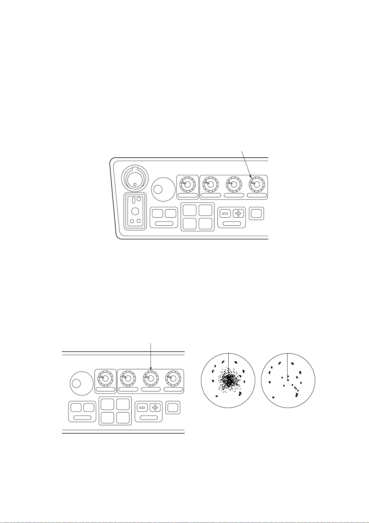
1.14 Suppressing Sea Clutter
In rough weather conditions returns from the sea surface are received over several miles
around own ship and mask close targets. This situation can be improved by properly
adjusting the [A/C SEA] (Anti-Clutter Sea) control.
[A/C SEA] control
OFF ON
EBL
BRILLIANCE A/C RAIN A/C SEA GAIN
#1 #2
#3 #4
RANGE
STBY
TX
Figure 1-14 Control head, A/C SEA effect
[A/C SEA] control off
[A/C SEA] control
adjusted
1-15
Page 27
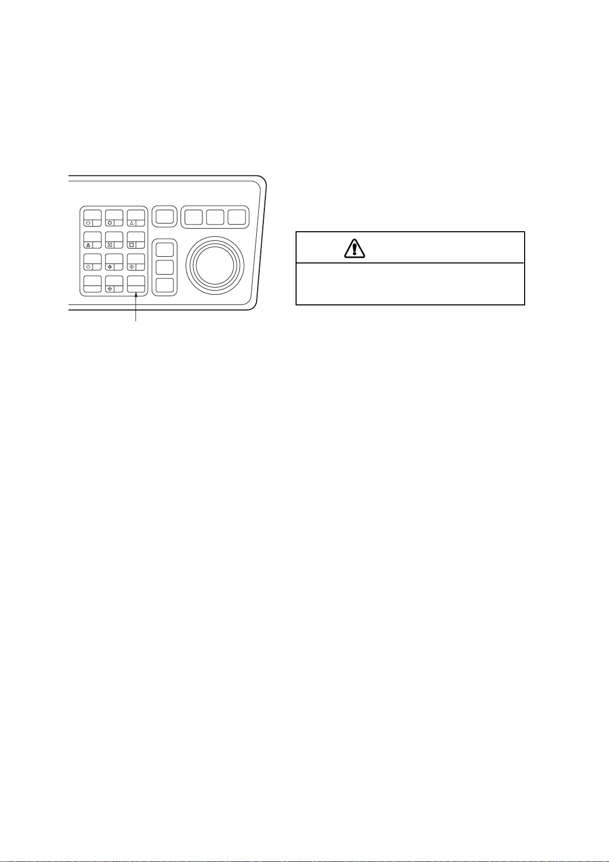
1.14.1 Automatic anti-clutter control
The easiest way to suppress the surface clutter is to use the automatic anti-clutter control.
Press the [A/C AUTO] key to turn the A/C AUT O circuit on or off. A/C AUT O appears at the
bottom left-hand corner of the screen when the A/C AUTO circuit is on.
Use of a function key is also a good method for reducing sea clutter. For this purpose,
presetting is required. Consult a FURUNO representative.
HL
PANEL
MODE
OFF
OFF
CENTER
EBL
TARGET
TRAILS
CANCEL
BRILL
2
1
LOST
VECTOR
CHART
ALIGN
CU, TM
RESET
TARGET
5
MARK
8
A/C
AUTO
0
ENTER
4
7
[A/C AUTO] key
AUDIO
RADAR
OFF
3
6
TARGET
9
TARGET
CANCEL
MENU
ACQ
DATA
NAV
PLOT
MENU
MENU
The auto A/C function can erase weak
targets.
Figure 1-15 Control head
CAUTION
1.14.2 Manual anti-clutter control
From the fully counterclockwise position, slowly turn the [A/C SEA] control clockwise. For
optimum target detection, you should leave speckles of the surface return slightly visible.
The anti-clutter sea control is often referred to as STC (Sensitivity Time Control) which
decreases the amplification of the receiver immediately after a radar pulse is transmitted,
and progressively increases the sensitivity as the range increases.
A common mistake is to over-adjust the [A/C SEA] control so that the surface clutter is
completely removed. By rotating the control fully clockwise, you will see how dangerous
this can be; a dark zone is created near the center of the screen and close-in targets can
be lost. This dark zone is even more dangerous if the gain has not been properly adjusted.
Always leave a little surface clutter visible on the screen. If no surface clutter is observed
(on very calm waters), set the control at the fully counterclockwise position.
1-16
Page 28
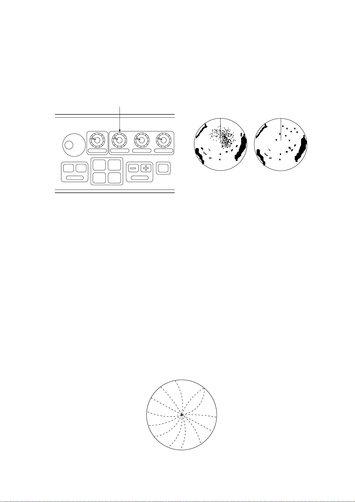
1.15 Suppressing Precipitation Clutter
In adverse weather conditions, clouds, rain or snow produce a lot of spray-like spurious
echoes and impairs target detection over a long distance. This situation can be improved
by using a function key provided that it is so programmed. If the function key fails to offer
a favorable suppression of the rain clutter, adjust the [A/C RAIN] control on the control
head.
[A/C RAIN] control
BRILLIANCE A/C RAIN A/C SEA GAIN
OFF ON
EBL
#1 #2
#3 #4
RANGE
STBY
TX
[A/C RAIN] control
off
[A/C RAIN] control
adjusted
Figure 1-16 Control head, A/C RAIN effect
The [A/C RAIN] control adjusts the receiver sensitivity as the [A/C SEA] control does but
rather in a longer time period (longer range). Clockwise rotation of this control increases
the anti-clutter effect.
1.16 Interference Rejector
Mutual radar interference may occur in the vicinity of another shipborne radar operating in
the same frequency band. It is seen on the screen as a number of bright spikes either in
irregular patterns or in the form of usually curved spoke-like dotted lines extending from
the center to the edge of the picture. This type of interference can be reduced by activating
the interference rejector circuit.
The interference rejector is a kind of signal correlation circuit. It compares the received
signals over successive transmissions and suppresses randomly occurring signals. There
are three levels of interference rejection depending on the number of transmissions that
are correlated. These are indicated by the legends IR1, IR2 and IR3 at the upper left-hand
position of the screen.
Figure 1-17 Interference
1-17
Page 29

To activate the interference rejector;
1. Press the [RADAR MENU] key. The following appears.
[FUNCTIONS (1)]
1 TARGET TRAILS
2 TARGET ALARM (1 or 2)
3 ORIGIN MARK (1 to 10)
4 INDEX LINES
5 ZOOM
6 PULSE WIDTH
7 INT REJECT
8 ARPA
9 VIDEO PLOT
0 [FUNCTIONS (2)]
Figure 1-18 RADAR menu
2. Press the [7] key to select INT REJECT.
3. Successive presses of the key increase the effect of interference rejection, up to level
3. A fourth press deactivates the interference rejector . Switch off the interference rejector when no interference exists; otherwise weak targets may be lost.
Note: For stable reception of certain types of radar beacons (Racons) or SART (Search
and Rescue Radar Transponder) as required by SOLAS 1974 as amended 1988 (GMDSS),
it is recommended to turn the interference rejector off.
1.17 Measuring the Range
Use the fixed range rings to obtain a rough estimate of the range to a target. They are the
concentric solid circles about own ship, or the sweep origin. The number of rings is automatically determined by the selected range scale and their interval is displayed at the
upper-left position of the screen.
1.17.1 Adjusting range ring briliance
1. Press the [RADAR MENU] key to display the FUNCTIONS 1 menu.
2. Press the [0] key to display the FUNCTIONS 2 menu.
3. Press the [9] key to display the BRILLIANCE 1 menu.
[BRILLIANCE (1)]
1 [FUNCTIONS (2)]
2 RINGS BRILL OFF/DIM/M1/M2/BRT
3 EBL BRILL DIM/M1/M2/BRT
4 VRM BRILL DIM/M1/M2/BRT
5 +CURSOR BRILL OFF/DIM/M1/M2/BRT
6 CHAR BRILL DIM/M1/M2/BRT
7 MARK BRILL DIM/M1/M2/BRT
8 TRAIL BRILL DIM/M1/M2/BRT
9 HL BRILL DIM/M/BRT
0 [BRILLIANCE (2)]
1-18
Figure 1-19 BRILLIANCE 1 menu
Page 30
4. Press the [2] key to select RINGS BRILL.
5. Press the [2] key again. Each pressing gradually increases the brightness of the rings
in 4 steps and the fifth pressing erases them.
6. Press the [ENTER] key to confirm you selection.
7. Press the [RADAR MENU] key to close the menu.
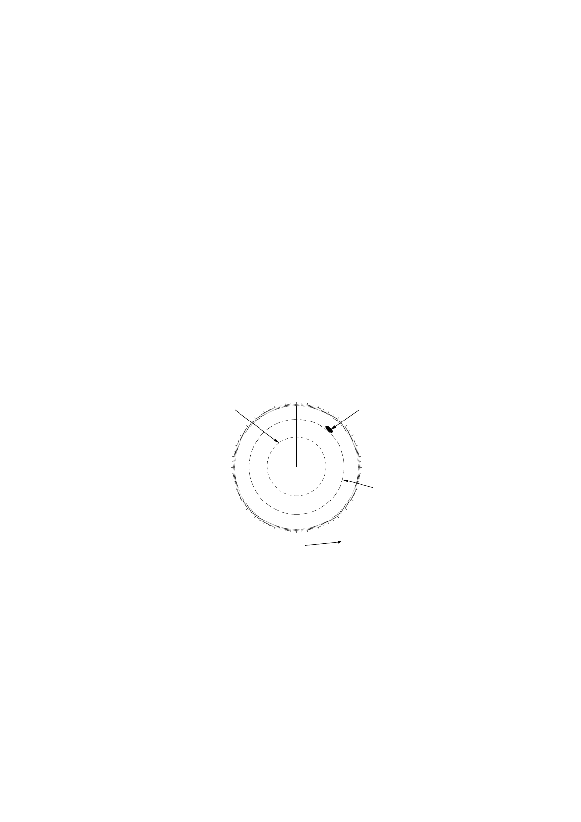
1.17.2 Measuring the range with the VRM
Use the V ariable Range Markers (VRMs) for more accurate measurement of the range to
a target. There are two VRMs, No. 1 and No. 2, which appear as dashed rings so that you
can discriminate them from the fixed range rings. The two VRMs can be distinguished
from each other by different lengths of dashes.
1. Press the [VRM ON] key to display either of the VRMs. Successive presses of the
[VRM ON] key toggle the active VRM between No. 1 and No. 2 and the currently active
VRM readout is marked with >.....<.
2. Turning the VRM control, align the active variable range marker with the inner edge of
the target of interest and read its distance at the lower-right corner of the screen. Each
VRM remains at the same geographical distance when you operate the RANGE+ or
RANGE- key . This means that the apparent radius of the VRM ring changes in proportion to the selected range scale.
3. Press the [VRM OFF] key to key to erase each VRM.
000
010
350
340
No.1
VRM
290
280
270
260
250
330
320
310
300
240
230
220
210
200
190
Active VRM is identified
with this marker.
020
030
040
050
060
120
130
140
150
160
170
180
VRM
>0.66SM<
1.18SM
Figure 1-20 How to measure range with VRM
Target
blip
070
080
090
100
No.2
110
VRM
1-19
Page 31
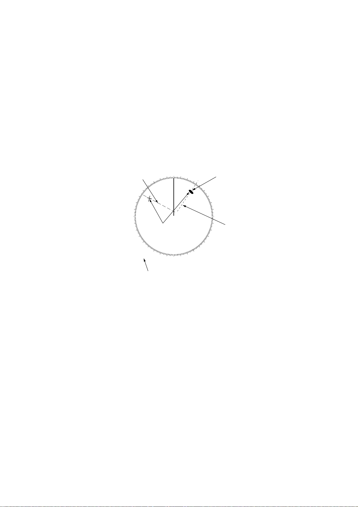
1.18 Measuring the Bearing
Use the Electronic Bearing Lines (EBLs) to take bearings of a target. There are two EBLs,
No. 1 and No. 2, which are toggled by successive presses of the [EBL ON] key. Each EBL
is a straight dashed line extending out from the own ship position up to the circumference
of the radar picture. The fine dashed line is the No. 1 EBL and the coarse dashed one is
the No. 2 EBL.
1. Press the [EBL ON] key to display either of the EBLs. Successive presses of the [EBL
ON] key toggle the active EBL between No. 1 and No. 2 and the currently active EBL
readout is marked with >... <.
2. Rotate the EBL rotary control clockwise or counterclockwise until the active EBL bisects the target of interest, and read its bearing at the lower-left corner of the screen.
3. Press the [EBL OFF] key to erase each EBL.
EBL
>032.5°T<
298.0°T
No.2
EBL
330
320
310
300
290
280
270
260
250
240
230
220
Range markers
on EBLs
210
000
010
350
340
200
190
020
030
040
140
150
160
170
180
Target
blip
050
060
070
080
090
100
No.1
110
120
130
EBL
Active EBL is indicated with this marker.
Figure 1-21 How to measure bearing with EBL
The EBL readout is affixed by “R” (relative) if it is relative to own ship’s heading, “T” (true)
if it is referenced to the north, as determined by the RADAR 1 menu settings.
Each EBL carries a range marker, or a short line crossing the EBL at right angles. Its
distance from the EBL origin is indicated at the VRM readout whether or not the corresponding VRM is displayed. The range marker changes its position along the EBL with the
rotation of the VRM control.
1-20
Page 32

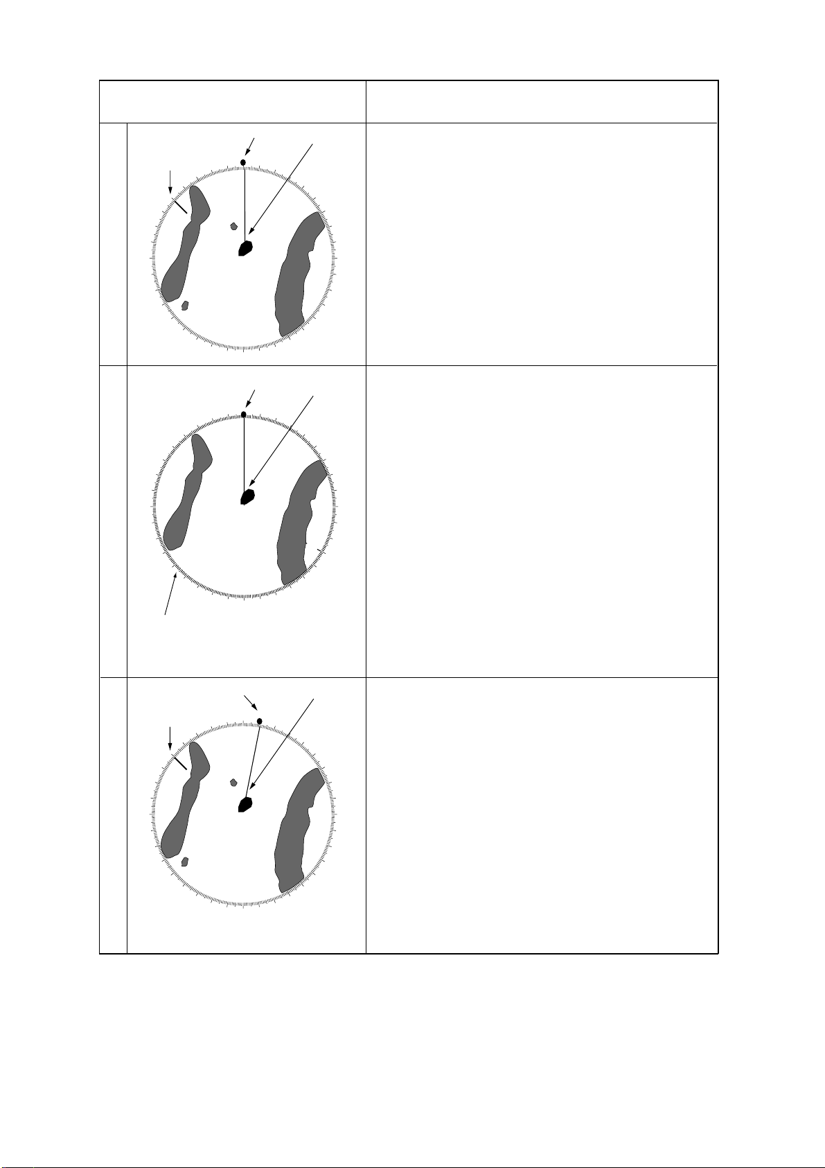
1.19 Collision Assessment by Offset EBL
The origin of the EBL can be placed anywhere with the trackball to enable measurement
of range and bearing between any two targets. This function is also useful for assessment
of the potential risk of collision. To assess possibility of collision:
1. Press the [EBL ON] key to display or activate an EBL (No. 1 or 2).
2. Place the cursor (+) on a target appearing as threatening (A in the illustrated example)
by operating the trackball.
3. Press the [EBL OFFSET] key on the mode panel, and the origin of the active EBL shifts
to the cursor position. Press the [EBL OFFSET] key again to anchor the EBL origin.
4. After waiting for a few minutes (at least 3 minutes), operate the EBL control until the
EBL bisects the target at the new position (A1). The EBL readout shows the target
ship’s course, which may be true or relative depending on the settings on the RADAR
1 menu.
If relative motion is selected, it is also possible to read CP A (Closest Point of Approach)
by using a VRM as shown below (Figure (a)). If the EBL passes through the sweep
origin (own ship) as illustrated (Figure (b)), the target ship is on a collision course.
5. To return the EBL origin to the own ship’s position, press the [EBL OFFSET] key again.
000
010
210
330
350
340
A
1
A
200
190
180
170
020
160
030
150
040
050
060
070
080
090
100
110
120
130
140
000
010
300
290
280
270
260
250
240
No. 1 EBL
EBL
> 150.3°R<
310
230
220
320
350
340
330
A
1
A
210
200
190
180
170
020
160
030
150
040
050
130
140
(a) Evaluating course of target ship in RM
120
060
070
110
080
100
090
290
280
270
260
250
No.1 EBL
EBL
> 150.3°R<
(b) Target ship on collision course
320
310
300
240
230
220
Figure 1-22 Collision assessment with the offset EBL
1-21
Page 33

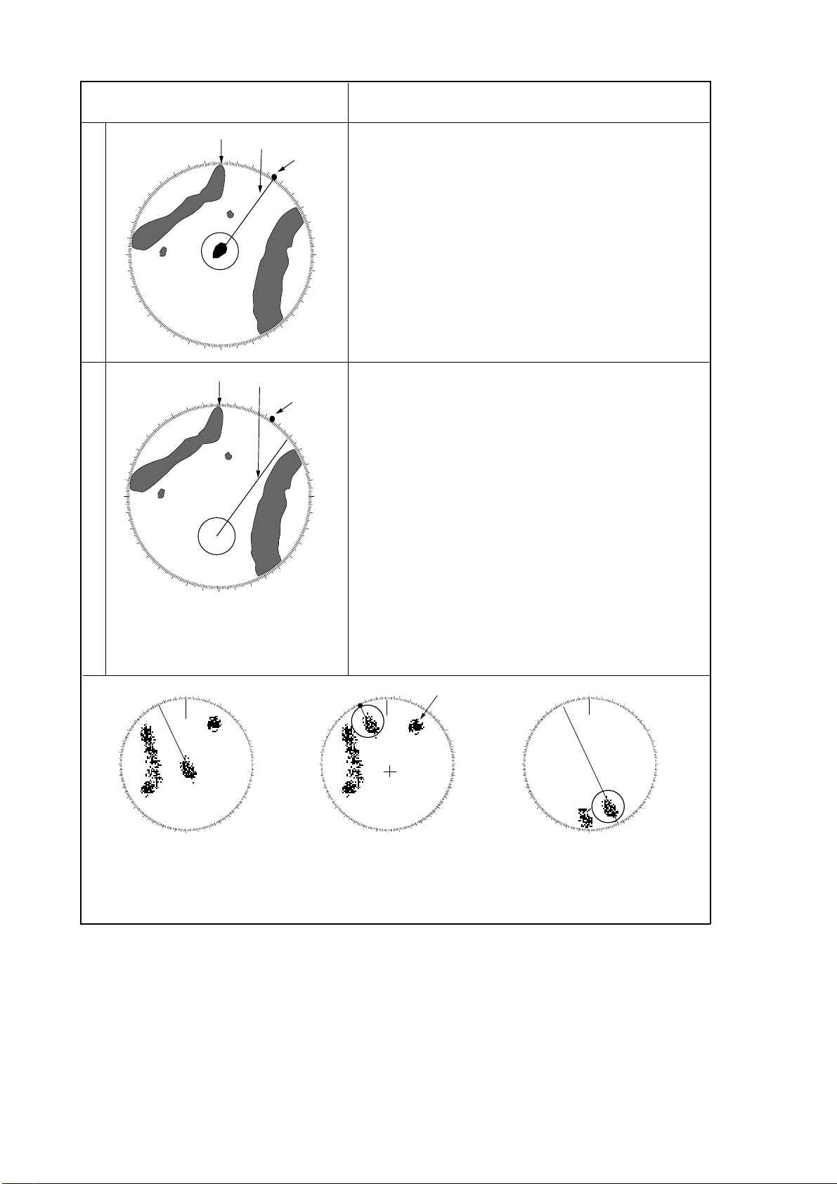
1.20 Measuring Range and Bearing Between Two Targets
1. Press the [EBL OFFSET] key, and place the origin of the No. 1 EBL, for example, on a
target of interest (target 1 in the illustrated example), by operating the trackball.
2. Turn the EBL control until the EBL passes through another target of interest (target 2).
3. Turn the VRM control until the range marker aligns with target 2. The active VRM
readout at the lower-right corner of the screen indicates the distance between the two
targets.
You can repeat the same procedure on third and fourth targets by using the No. 2 EBL
and No. 2 VRM.
Bearing is shown relative to own ship with suffix “R” or as a true bearing with the suffix
“T” depending on EBL relative/true settings on the RADAR 1 menu.
5. To return the EBL origin to the own ship position, press the [EBL OFFSET] key again.
No.1 EBL
> 140.0°T<
335.2°T
Range marker
330
320
310
300
290
EBL origin
240
230
220
Target 1
210
280
270
260
250
EBL
350
340
Target 2
200
190
000
R1
180
010
170
R2
020
160
030
150
040
140
050
060
070
080
090
100
110
120
130
VRM
> 0.500SM<
0.980SM
No.1 VRM
No.2 VRM
Range/bearing between targets 1 and 2
Figure 1-23 Measuring range and bearing between two targets
1-22
Page 34

1.21 Setting a Target Alarm Zone
CAUTION
The target alarm should not be relied
upon as the sole means for detecting
possible collision situations. The operator of a ship is not relieved of the responsibility to keep lookout for possible
collisions, whether or not the radar is
in use.
The target alarm serves to alert the navigator to targets (ships, landmasses, etc.) entering
a certain area with visual and audible alarms.
The outer and inner boundaries can be set at any distance. The sector of the zone can be
set anywhere between 0 and 360 degrees in any direction.
The target alarm is given to targets
having a certain level of echo strength.
This level does not always imply a landmass, reef, ships or other surface
objects but can mean returns from the
sea surface or precipitation. Properly
adjust the [GAIN], [A/C SEA], and
[A/C RAIN] controls to reduce noise to
avoid generation of an alarm against a
false target.
CAUTION
1.21.1 Setting a target alarm zone
1. Referring to Figure 1-24, use the trackball to place the cursor (+) at point “A”.
2. Press the [RADAR MENU] key to show the FUNCTIONS 1 menu.
3. Press the [2] key to set start point (point “A”) of the alarm zone. The message TGT
ALARM1 (or 2) SET appears at the bottom-right corner of the screen.
4. Move the cursor (+) to point “B” and press the [2] key again. Then, the target alarm
zone as illustrated is created and the label TGT ALARM1 (or 2) appears instead of TGT
ALARM1 (or 2) SET at the lower-right corner of the screen.
Note 1: If you wish to create a target alarm zone having a 360-degree coverage around
own ship, set point “B” in almost the same direction (approx. ±3) as point “A” and press
the [2] key.
Note 2: If you change the range scale to less than half of the TAZ, the warning TGT
ALARM1 (or 2) OUT appears instead of TGT ALARM1 (or 2).
5. Two alarm zones can be set as described above. Press [ENTER] and [2] keys in that
order while displaying the FUNCTIONS 1 menu and repeat the above steps.
1-23
Page 35

Target Alarm Zone (TAZ)
m
040
050
060
070
080
090
100
When the radar has an ARPA board ARP-26, a total of
110
four alarm zones (2 each TAZ and GZ) may be set.
120
130
140
The 2nd TAZ or 2nd GZ is available only when the
1st TAZ or 1st GZ is valid.
270
280
260
290
250
300
240
310
230
320
220
210
330
200
340
000
010
350
A
190
180
170
020
030
B
150
160
Figure 1-24 How to set target alarm zone
1.21.2 Acknowledging alarm
A target entering the watch zone produces both visual (flashing) and audible (beeping)
alarms. To silence the audible alarm, press the [2] key shortly on the FUNCTIONS 1 menu
and the label TGT ALARM1 ACK replaces TGT ALARM1 on the display.
This will deactivate the audible alarm but will not stop the flashing of the target in the target
alarm zone. To reactivate the audible alarm, press the [2] key again on the FUNCTIONS 1
menu.
When an external buzzer is connected, the audible alarm does not stop until the target
alarm is deactivated.
1.21.3 Deactivating target alarm
Hold the [2] key depressed for at least five seconds on the FUNCTIONS 1 menu.
1.21.4 Inward and outward target alarms
An inward or outward target alarm can be selected on the RADAR 2 menu. The inward
target alarm generates visual and audible warnings when a target enters the guard zone
from any direction. The outward target alarm is produced when a target leaves the target
alarm zone.
1-24
(a) Inward target alarm (b) Outward target alar
Figure 1-25 Inward and outward target alarm zones
Page 36

1.22 Off-Centering
Own ship position, or sweep origin, can be displaced to expand the view field without
switching to a larger range scale. The sweep origin can be off-centered to the cursor
position, but not more than 75% of the range in use; if the cursor is set beyond 75% of the
range scale, the sweep origin will be off-centered to the point of 75% of the limit.
This feature is not available on the longest range scale or in the true motion mode. The
number of range rings increases, keeping the original range intervals unchanged.
To off-center the radar picture:
1. Place the cursor at a position where you wish to move the sweep origin by operating
the trackball.
2. Press the [OFF CENTER] key. Then, the sweep origin is off-centered to the cursor
position.
3. To cancel off-centering, press the [OFF CENTER] key again.
1.23 Echo Stretch
On long ranges target echoes tend to shrink in the bearing direction, making them difficult
to see. On short and medium ranges such as 1.5, 3 and 6 SM scales, the same size
targets get smaller on screen as they approach own ship. These are due to the inherent
property of the radiation pattern of the antenna. To enhance target video, use the echo
stretch function. There are 3 settings: echo stretch 1 (ES1) to enlarge in bearing direction
for long range detection, echo stretch 2 (ES2) to enlarge in range direction and echo
stretch 3 (ES3) to enlarge in both bearing and range directions.
To activate the echo stretch:
1. Press the [RADAR MENU] key to show the FUNCTIONS 1 menu.
2. Press the [0] key to display the FUNCTIONS 2 menu.
[FUNCTIONS (2)]
1 [FUNCTIONS (1)]
2 BKGD COLOR BLK(GRN CHAR)/
BLK(RED CHAR)/
BLU (ECHO AREA)
BLU/
BRT BLU
3 ECHO STRETCH OFF/1/2/3
4 ECHO AVERAGE OFF/1/2/3
5 ECHO COLOR YEL/GRN/COLOR
6 SHIP SPEED LOG/NAV/MAN
MAN = 00.0KT
(STW/SOG)
7 SET, DRIFT OFF/MAN
SET = 000.0°
DRIFT = 00.0KT
8 INDEX LINES NO. 2 VRM/MAN
9 [BRILLIANCE (1)]
0 [FUNCTIONS (3)]
MAN = 00.00SM
Figure 1-26 FUNCTIONS 2 menu
1-25
Page 37

3. Press the [3] key to select ECHO STRETCH.
4. Press the [3] key until Echo Stretch option 1, 2, 3 or OFF as desired is highlighted.
5. Press the [ENTER] key to conclude your selection followed by the [RADAR MENU] key
to close the FUNCTIONS menu. Selected setting is indicated on the left side of the
radar display.
(a) ES1-Enlarged
in bearing direction
(b) ES2-Enlarged
in range direction
(c) ES3-Enlarged
in both range and
bearing directions
Figure 1-27 Echo stretch
Notes on use of echo stretch
1) If the 1.5 SM range is preset with a pulsewidth of S1 or S2, and the 3 SM scale with
S2, the echo stretch is not available on these range scales.
2) The echo stretch magnifies not only small target pips but also returns (clutter) from sea
surface, rain and radar interference. For this reason make sure these types of interference have been sufficiently suppressed before activating this function.
1.24 Echo A veraging
The echo average feature effectively suppresses sea clutter . Echoes received from stable
targets such as ships appear on the screen at almost the same position every rotation of
the antenna. On the other hand, unstable echoes such as sea clutter appear at random
positions.
To distinguish real target echoes from sea clutter, this radar performs scan-to-scan correlation. Correlation is made by storing and averaging echo signals over successive picture
frames. If an echo is solid and stable, it is presented in its normal intensity. Sea clutter is
averaged over successive scans resulting in the reduced brilliance, making it easier to
discriminate real targets from sea clutter.
To properly use the echo average function, it is recommended to first suppress sea clutter
with the [A/C SEA] control and then do the following:
1. Press the [RADAR MENU] key and the [0] key to show the FUNCTIONS 2 menu.
1-26
Page 38

[FUNCTIONS (2)]
N
1 [FUNCTIONS (1)]
2 BKGD COLOR BLK(GRN CHAR)/
BLK(RED CHAR)/
BLU (ECHO AREA)
BLU/
BRT BLU
3 ECHO STRETCH OFF/1/2/3
4 ECHO AVERAGE OFF/1/2/3
5 ECHO COLOR YEL/GRN/COLOR
6 SHIP SPEED LOG/NAV/MAN
MAN = 00.0KT
(STW/SOG)
7 SET, DRIFT OFF/MAN
SET = 000.0°
DRIFT = 00.0KT
8 INDEX LINES NO. 2 VRM/MAN
9 [BRILLIANCE (1)]
0 [FUNCTIONS (3)]
MAN = 00.00SM
Figure 1-28 FUNCTIONS 2 menu
2. Press the [4] key to select ECHO AVERAGE.
3. Press the [4] key until echo average option 1, 2, 3 or OFF as desired is highlighted.
OFF: No averaging effect
1: Helps distinguish targets from sea clutter and suppresses brilliance of unstable
echoes.
2: Distinguishes small stationary targets such as navigation buoys.
3: Stably displays distant targets.
4. Press the [ENTER] key to conclude your selection followed by the [RADAR MENU] key
to close the FUNCTIONS menu.
(a) Echo average OFF (b) Echo average O
Figure 1-29 Echo averaging
Echo averaging uses scan-to-scan signal correlation technique based on the true motion
over the ground of each target. Thus, small stationary targets such as buoys will be shown
while suppressing random echoes such as sea clutter. T rue echo average is not however
effective for picking up small targets running
at high speeds over the ground.
CAUTION
Echo average is inoperable when a gyrocompass signal is not available. If you wish to
use this feature without a gyrocompass signal, consult a FURUNO representative.
Do not use the Echo Average feature
under heavy pitching and rolling; loss of
true targets can result.
1-27
Page 39

1.25 Electronic Plotting Aid (EPA)
A maximum 10 operator-selected targets can be plotted electronically to assess their motion
trend. Five past positions can be displayed for each of the plotted targets. If you enter a
6th plot on a certain target, the oldest plot (past position) will be erased.
A vector appears when you enter a second plot for the target and is updated each time a
new plot is entered. The vector shows the target motion trend based on its latest two plots.
The vector origin will move across the screen at a rate and direction defined by the calculated true course and speed until a next manual plotting.
Target data is shown in the data display area which shows bearing, course, speed, CPA,
TCPA, BCR, BCT calculated true course of targets, calculated true speed of targets.
Elapsed Time
0 : 03
0.439SM
122.7°T
254.2°T BT TRU
14.9KT BT TRU
0.4SM
0.0MIN
0.8SM
99.9MIN
Speed Reference
(Bottom Tracking
or Water Tracking)
000
010
270
260
280
290
250
300
240
310
230
320
220
210
330
340
200
350
190
180
170
020
160
030
040
01
Course
140
150
050
060
070
110
120
130
NOTES:
• Target 1 is on a collision course.
• TCPA calculated up to 99.9 min. TCPA
higher than this is shown as >*99.9MIN.
080
090
100
Vector Reference
(True or Relative)
RNG
BRG
CSE
01
SPD
CPA
TCPA
BCR
BCT>
EPA
TRUE VECTOR 6MIN BT
Vector Time
EPA DATA
Figure 1-30 Sample EPA display
T arget 01 in Figure 1-30 is on a collision course as the extension of the vector goes through
the own ship position. Placing the offset EBL on the target will be a help for assessment.
TCPA is counted up to 99.9 minutes and beyond this it is indicated as TCPA >* 99.9 MIN.
Note: EPA requires speed input (automatic or manual) and a heading signal. The vector
and data are updated automatically every 1-2 scenes between plot entries, but do not
neglect to plot a new position over a long period of time. The accuracy will be reduced.
Note the plots will be lost when the gyrocompass fails; start the plotting exercise again.
1-28
Page 40

1.25.1 Plotting a target
To perform electronic plotting:
1. Place the cursor(+) on a target of interest by operating the trackball.
2. Press the [ACQ] key and one of numeric keys, and the plot symbol with number appears at the cursor position.
3. Watching the EPA time shown at the screen center , wait for at least 30 seconds. Place
the cursor (+) on the target at its new location, press the [ACQ] key, and the same
numeric key for the target.
The plot symbol moves to the new target position and previous position is marked by a
small dot.
4. To acquire other targets, repeat the above steps selecting a different plot number.
Note: If a target once plotted is not plotted again within 10 minutes, the warning “UPDATE
PLOT” will appear in red on the bottom of the screen and the plot symbol of the target
flashes. If you want to continue plotting this target, reacquire it within five minutes. Otherwise, the target will be regarded as a “lost target” and its plot symbol and target data will
be erased. The larger the plotting interval, the less accurate the plotted target data. Plotting of each target should normally be made every three or six minutes as far as possible.
You can use a Watch Alarm to warn yourself every three or six minutes or whichever you
may set.
Within five seconds, you can cancel a last plot by the [TARGET CANCEL] key and make
a re-entry at a different position. After five seconds, the last entry is processed to produce
a vector .
1.25.2 True or relative vector
Vectors can be displayed relative to own ship’ s heading (Relative) or with reference to the
north (True). Press the [VECTOR] key to select the required mode. This feature is available in all presentation modes (gyrocompass must be working correctly). The current vector mode is indicated at the screen center.
1.25.3 Vector time
Vector time (or the length of vectors) can be set to 30 seconds, 1, 2, 3, 6, 12, 15 or 30
minutes and the selected vector time is indicated at the screen center.
1. Press the [PLOT MENU] key followed by the [1] key several times to select vector time
desired.
[EPA]
1 VECTOR TIME 30SEC/1/2/3/6/12/15/30MIN
2 COLLISION ALARM OFF/ON
CPA 0.0 SM
TCPA 00.0 MIN
3 MARK STD/LARGE
4 PLOT NO. OFF/ON
Figure 1-31 EPA menu
1-29
Page 41

2. Press the [ENTER] key to confirm your selection.
3. Press the [PLOT MENU] key to close the menu. The vector tip shows an estimated
position of the target after the selected vector time elapses. It can be valuable to extend the vector length to evaluate the risk of collision with any target.
1.25.4 Target data
The radar calculates motion trends (range, bearing, course, speed, CP A and TCPA) of all
plotted targets.
In the head-up and head-up true bearing modes, target bearing, course and speed shown
in the upper-right target data field become true (T) relative to north or relative (R) relative
to own ship in accordance with true/relative vector setting. In the north-up, course-up, and
True Motion modes, the target data field always displays true bearing, true course, and
speed over the ground.
Reading the target data
Press the [ACQ] key and corresponding numeric key, and the following target data is
displayed.
RNG/BRG (Range/Bearing): Range and bearing from own ship to last-plotted target with
suffix “T” (True) or “R” (Relative) plot symbol.
CSE/SPD (Course/Speed): Course and speed are displayed for the last-plotted target
with the suffix “T” (True) or ”R” (Relative) plot symbol.
CPA/TCPA: CPA (Closest Point of Approach) is the closest range a target will approach to
own ship. TCPA is the Time to CPA. Both CPA and TCPA are automatically calculated.
TCPA is counted up to 99.9 minutes and beyond this it is indicated as TCPA > *99.9 MIN.
BCR/BCT: BCR (Bow Cross Range) is the range at which a target will cross own ship’s
bow. BCT (Bow Cross Time) is the estimated time at which a target will cross own ship’s
bow. If BCR is negative, BCR/BCT readout is displayed as *.*.
1.25.5 Terminating target plotting
With EPA you can plot up to 10 targets. You may wish to terminate plotting of less important targets to newly plot other threatening targets.
By Symbol: To terminate plotting of a certain target, press the [TARGET CANCEL] key
and then press the corresponding plot number key.
With T rackball: Use the trackball to place the cursor (+) on a target which you do not want
to be tracked any longer, and then press the [TARGET CANCEL] key.
All Targets: To terminate plotting of all targets at once, press and hold the [TARGET
CANCEL] key until all plot symbols and marks disappear (in about three seconds).
1-30
Page 42
1.25.6 Setting CPA/TCPA alarm ranges
When the predicted CPA of any target becomes smaller than a preset CPA alarm range
and its predicted TCPA less than a preset TCPA alarm limit, the EPA releases an aural
alarm and displays the warning label COLLISION on the screen. In addition, the EPA
symbol changes to a triangle and flashes together with its vector.
Provided that this feature is used correctly , it will help prevent the risk of collision by alerting you to threatening targets. It is important that GAIN, A/C SEA, A/C RAIN and other
radar controls are properly adjusted.
CPA/TCPA alarm ranges must be set up properly taking into consideration the size, tonnage, speed, turning performance and other characteristics of own ship.
CAUTION
The CPA/TCPA alarm feature should
never be relied upon as the sole means
for detecting the risk of collision. The
navigator is not relieved of the responsibility to keep visual lookout for avoiding
collisions, whether or not the radar or
other plotting aid is in use.
To set the CPA/TCPA alarm ranges:
1. Press the [PLOT MENU] key to show the EPA menu.
2. Press the [2] key to select COLLISION ALARM ON. At this point, a highlight cursor
appears at the “CPA x.x NM” field.
3. Enter the CPA alarm range in nautical miles (0.0 to 9.9 nm) without omitting leading
zeroes, if any, and press the [ENTER] key. The highlight cursor now moves to the
“TCPA xx.x MIN” field.
4. Enter the TCPA alarm limit in minutes (1.0 to 99.0 minutes) without omitting leading
zeroes, if any, and press the [ENTER] key.
5. Press the [PLOT MENU] key to close the menu.
1.25.7 Silencing CPA/TCPA audible alarm
Press the [AUDIO OFF] key to acknowledge and silence the CPA/TCPA audible alarm.
The warning label COLLISION and the flashing of the triangle plot symbol and vector
remain on the screen until the dangerous situation is gone or you intentionally terminate
tracking of the offending target by using the [TARGET CANCEL] key.
1-31
Page 43

1.25.8 Changing size of the plotting symbols
You can change the size of the plotting symbols as follows:
1. Press the [PLOT MENU] key to show the EPA menu.
2. Press the [3] key two or three times until plot symbol size option STD (standard) or
LARGE is highlighted.
3. Press the [ENTER] key to conclude your selection followed by the [PLOT MENU] key
to close the PLOT menu.
1.26 Target Trails
It is possible to display the trails of radar echoes in the form of synthetic afterglow. The
afterglow can be selected in a single tone or gradual shading as set on the RADAR 1
menu.
1.26.1 True or relative target trails
Y ou may display target trails in true or relative motion (only true trail on TM). Relative trails
show relative movements between targets and own ship. True motion trails require a gyrocompass signal and speed input to cancel out own ship’s movement and present true
target movements in accordance with their over-the-ground speeds and courses.
(a) True target trails
(No smearing of
stationary targets)
(b) Relative target trails
(All targets moving
relative to own ship)
Figure 1-32 Target trails
Note: When true trail is selected on the RM mode, the legend TRUE TRAIL appears in
red. The TM modes always displays True trails.
To select true or relative target trail presentation:
1. Press the [RADAR MENU] key followed by [0], [0] and [2] to display the RADAR 1
menu.
1-32
Page 44

[RADAR (1)]
1 [FUNCTIONS (3)]
2 EBL1 REL/TRUE
3 EBL2 REL/TRUE
4 VRM1* NM/km
5 VRM2* NM/km
6 TRAIL REL/TRUE
7 TRAIL GRAD SGL/MULT
8 [PULSE WD 1]
9 [PULSE WD 2]
0 [RADAR (2)]
* Does not appear
on SM-type radar.
Figure 1-33 RADAR 1 menu
3. Press the [6] key to select menu item 6 TRAIL.
4. Press the [6] key to select (or highlight) REL (Relative) or TRUE option.
5. Press the [ENTER] key to confirm your selection, and then press the [RADAR MENU]
key to close the menu.
1.26.2 Target trail gradation
Target trails may be shown in monotone or gradual shading. Gradual shading paints the
trails getting thinner with time just like the afterglow on an analog PPI radar.
Monotone Gradual Shading
Figure 1-34 Trail gradation
1. Press the [RADAR MENU] key followed by [0], [0] and [2] to display the RADAR 1
menu.
3. Press the [7] key to select menu item 7 TRAIL GRAD.
4. Press the [7] key to select SGL (single tone) or MULT (multiple shading) option.
5. Press the [ENTER] key to confirm your selection; then [RADAR MENU] key to close
the menu.
1.26.3 Displaying, erasing target trails
Press the [RADAR MENU] key followed by the [1] key to activate or deactivate the target
trails feature.
[FUNCTIONS (1)]
1 TARGET TRAILS
2 TARGET ALARM (1 or 2)
3 ORIGIN MARK (1 to 10)
4 INDEX LINES
5 ZOOM
6 PULSE WIDTH
7 INT REJECT
8 ARPA
9 VIDEO PLOT
0 [FUNCTIONS (2)]
Figure 1-35 FUNCTIONS 1 menu
1-33
Page 45

Each press of the [1] key within five seconds cyclically changes target trail length (time) as
below:
OFF - 30 s - 1 min - 3 min - 5 min - 15 min - 30 min - continuous - OFF
The current target trail setting is displayed at the lower-right corner of the screen.
Suppose that “3 MIN” has just been selected. If the [1] key is hit on the FUNCTION 1 menu
more than five seconds later, target trails are removed from the display (memory still alive
with target trail timer count going on). Next hitting of the key calls out the target trails on
the screen. To proceed to longer plot intervals, successively push the [1] key with a hitand-release action. The larger the target trail length, the larger the target trail plot interval.
Note: Holding the [1] key depressed for about three seconds on the FUNCTION 1 menu
will cause a loss of target trail data so far stored in the memory.
1.26.3 Resetting target trails
To reset (or clear) the target trail memory, hold the [TARGET TRAILS CANCEL] key depressed for about three seconds. Target trails are cleared and the trailing process restarts
from time count zero at current target trail plot interval. When the memory assigned to
target trails becomes full the target trail timer at the lower-right corner of the screen freezes
and the oldest trails are erased to show the latest trails.
1.27 Parallel Index Lines
Parallel index lines are useful for keeping a constant distance between own ship and a
coastline or a partner ship when navigating. Index lines are drawn in parallel with the No.
2 EBL (No. 2 EBL must be active). The orientation of the index lines is controlled with the
EBL control (without effecting the EBL indication) and the intervals between the lines adjusted with the VRM rotary control (provided that No. 2 VRM is active).
The maximum number of the index lines to display can be set for 2, 3 or 6 on the INITIAL
SETTING 3 menu.
NO.2 EBL
Parallel Index Lines
1-34
Figure 1-36 Parallel index lines
Page 46

1.27.1 Displaying, erasing the index lines
1. Press [RADAR MENU], [4] key to display or erase the index lines.
[FUNCTIONS (1)]
1 TARGET TRAILS
2 TARGET ALARM (1 or 2)
3 ORIGIN MARK (1 to 10)
4 INDEX LINES
5 ZOOM
6 PULSE WIDTH
7 INT REJECT
8 ARPA
9 VIDEO PLOT
0 [FUNCTIONS (2)]
Figure 1-37 FUNCTIONS 1 menu
2. Orient the index lines in a desired direction with the EBL rotary control. The azimuth of
the index lines appear at the bottom of the screen.
1.27.2 Adjusting index line intervals
1. Press [RADAR MENU], [0] to show the FUNCTIONS 2 menu.
[FUNCTIONS (2)]
1 [FUNCTIONS (1)]
2 BKGD COLOR BLK(GRN CHAR)/
BLK(RED CHAR)/
BLU (ECHO AREA)
BLU/
BRT BLU
3 ECHO STRETCH OFF/1/2/3
4 ECHO AVERAGE OFF/1/2/3
5 ECHO COLOR YEL/GRN/COLOR
6 SHIP SPEED LOG/NAV/MAN
MAN = 00.0KT
(STW/SOG)
7 SET, DRIFT OFF/MAN
SET = 000.0°
DRIFT = 00.0KT
8 INDEX LINES NO. 2 VRM/MAN
9 [BRILLIANCE (1)]
0 [FUNCTIONS (3)]
MAN = 00.00SM
Figure 1-38 FUNCTIONS 2 menu
2. Press the [8] key to select menu item 8 INDEX LINES.
3. Press the [8] key to select (or highlight) NO. 2 VRM or MAN (manual) option.
4. Press the [ENTER] key to conclude your selection.
5. If you selected MAN in step 3 above, “MAN = 00.00NM” appears at the bottom of the
FUNCTIONS 2 menu. Enter a desired line interval (without omitting leading zeroes) by
hitting numeric keys and then press the [ENTER] key. There are choices of 2, 3 and 6
index lines but the number of lines visible on the screen may be less than 6 depending
on the line intervals.
1-35
Page 47
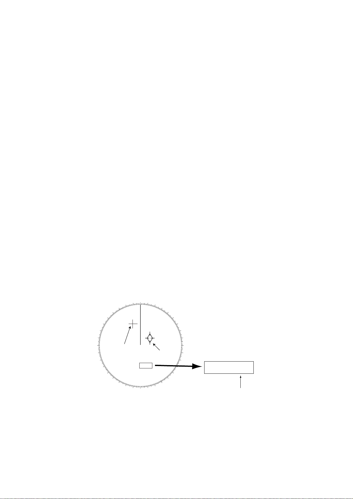
6. If you selected NO. 2 VRM in step 3 above, make sure that the No. 2 VRM is active and
adjust the spacing between the index lines by operating the VRM control.
7. Press the [RADAR MENU] key to close the FUNCTIONS 2 menu.
1.28 Origin Mark
Y ou can mark any reference points, prominent target or a point of particular interest using
the origin mark feature. These marks (max 10) are geographically fixed, that is, ground
stabilized. To display the origin marks, heading signal and position data are required.
1.28.1 Inscribing an origin mark
1. Using the trackball, place the cursor (+) at a point where you want to place a reference
mark.
2. Press the [RADAR MENU] key to show the FUNCTIONS 1 menu.
3. Press the [3] key. The origin mark appears at the cursor position of which range and
bearing are indicated at the screen center.
4. T o measure the range and bearing to a target of interest from the origin mark, move the
cursor to the target of interest. Then, the range and bearing from the origin mark to the
target are shown at the screen center.
5. To enter another origin mark, press the [ENTER] key and the [3] key in the FUNCTIONS 1 menu. Place the cursor where you want to place the origin mark, then press
the [3] key.
6. To erase the origin mark, select the origin mark number in the FUNCTIONS 1 menu by
pressing the [ENTER] key and the [3] key repeatedly, and then press the [3] key once
again.
000
010
270
260
280
290
250
300
240
310
230
320
220
330
210
350
340
Cursor
200
190
180
170
020
160
1
030
040
Origin
Mark
140
150
130
050
120
060
070
080
090
100
110
01 − > +
0.101SM
254.3°T
Range and bearing
from origin mark to
cursor
1-36
Figure 1-39 Origin mark
Page 48

1.28.2 Attaching ID number or symbol to origin marks
Origin marks may be affixed with ID numbers or symbols corresponding to the keys in use.
1. Press [RADAR MENU], [0], [0], [2], [0] and [0] to show the RADAR 3 menu.
2. Press the [5] key twice to select the number or symbol.
3. Press the [ENTER] key to conclude your selection.
1.29 Zoom
The zoom function enlarges an area of interest as large as twice the normal viewing. Note
that the zoom feature is inoperative when the display is off centered.
1. Place the cursor (+) close to the point of interest by operating the trackball.
2. Press the [RADAR MENU] key to show the FUNCTIONS 1 menu.
3. Press the [5] key. The area around the cursor and own ship is enlarged twice as large
as the original size and the label ZOOM appears at the lower-left corner of the screen.
4. To cancel zoom, press the [5] key again on the FUNCTIONS 1 menu.
1.30 Markers
1.30.1 Heading marker and heading line
The heading marker and the heading line indicate the ship’s heading in all presentation
modes. The heading line is a line from the own ship position to the outer edge of the radar
display area and appears at zero degrees on the bearing scale in head-up mode, and in
the north-up and true motion modes it changes with ship’s movement. The heading marker
appears as a small circle on the bearing scale to indicate the heading when the display is
off-centered or is in north-up or TM mode.
Temporarily erasing heading line
To temporarily extinguish the heading line to look at targets existing dead ahead of own
ship, press the [HL OFF] key. The heading line reappears when the key is released.
1.30.2 North marker
The north marker appears as a short dashed line. In the head-up mode, the north marker
moves around the bearing scale in accordance with the gyrocompass signal.
1.30.3 Stern marker
The stern marker (a dot-and-dash line) appears opposite to the heading line. This marker
can be displayed provided that STERN MK ON is selected on the RADAR 2 menu.
1-37
Page 49
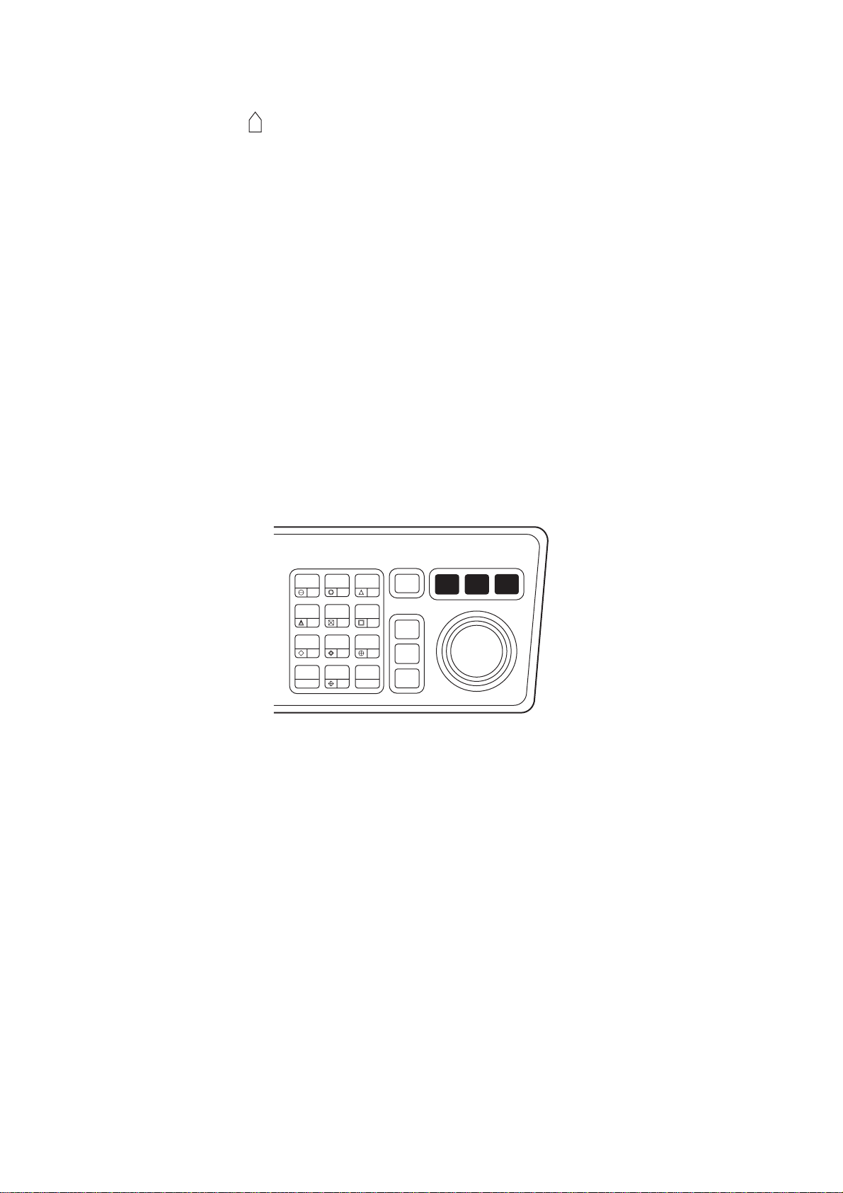
1.30.4 Own ship symbol
The own ship symbol ( ) can be displayed/erased on the RADAR 2 menu. The symbol is
scaled to indicate the length and beam of the vessel. If the largest dimension of the symbol gets smaller than 6 mm, the symbol will disappear and own ship will be represented
with a small dot or circle depending on the range in use. Details should be entered during
installation.
1.31 Menu Keys
Three menu keys are provided on the right hand corner of the control head: [RADAR
MENU], [PLOT MENU] and [NAV MENU].
RADAR MENU: Permits setting of basic radar parameters.
PLOT MENU: Permits setting of Electronic Plotting Aid (EPA) parameters or the optional
ARP A ARP-26.
NAV MENU: Provides a choice of navigation data for on-screen display . Also selects dis-
play data for the optional Video Plotter.
HL
PANEL
MODE
OFF
OFF
CENTER
EBL
TARGET
TRAILS
CANCEL
AUDIO
BRILL
2
1
VECTOR
4
CHART
ALIGN
7
CU, TM
RESET
3
LOST
TARGET
5
6
MARK
8
9
A/C
AUTO
0
ENTER
OFF
ACQ
TARGET
DATA
TARGET
CANCEL
RADAR
MENU
PLOT
MENU
NAV
MENU
Figure 1-40 Control head, menu keys
Note: Menu automatically goes off in 30 seconds if you do not press a key.
1-38
Page 50

1.32 RADAR 1, 2 and 3 Menu Settings
[RADAR MENU] key
[FUNCTIONS (1)]
1 TARGET TRAILS
2 TARGET ALARM (1 or 2)
3 ORIGIN MARK (1 to 10)
4 INDEX LINES
5 ZOOM
6 PULSE WIDTH
7 INT REJECT
8 ARPA
9 VIDEO PLOT
0 [FUNCTIONS (2)]
[0] key [1] key
[FUNCTIONS (2)]
1 [FUNCTIONS (1)]
2 BKGD COLOR BLK(GRN CHAR)/
BLK(RED CHAR)/
BLU (ECHO AREA)
BLU/
BRT BLU
3 ECHO STRETCH OFF/1/2/3
4 ECHO AVERAGE OFF/1/2/3
5 ECHO COLOR YEL/GRN/COLOR
6 SHIP SPEED LOG/NAV/MAN
MAN = 00.0KT
(STW/SOG)
7 SET, DRIFT OFF/MAN
SET = 000.0°
DRIFT = 00.0KT
8 INDEX LINES NO. 2 VRM/MAN
9 [BRILLIANCE (1)]
0 [FUNCTIONS (3)]
MAN = 00.00 SM
[0] key [1] key
[FUNCTIONS (3)]
1 [FUNCTIONS (2)]
2 [RADAR (1)]
3 [FUNCTION KEY 1]
4 [FUNCTION KEY 2]
5 [FUNCTION KEY 3]
6 [FUNCTION KEY 4]
7 [RADAR *1 1/2
8 INTER SWITCH
9 GYRO SETTING
EBL= xxx.x°
0 [FUNCTIONS (4)]
[2] key
*1: RADAR: Select 1 for single radar installation or for
connecting to antenna No.1 on dual radar installation.
Select 2 for connecting to antenna No.2 on dual radar
installation.
*2: ALARM: Audio alarm level is 65/70/80 db (A).
[RADAR (1)]
1 [FUNCTIONS (3)]
2 EBL 1 REL/TRUE
3 EBL 2 REL/TRUE
4 VRM 1*3 NM/km
5 VRM 2*3 NM/km
6 TRAIL REL/TRUE
7 TRAIL GRAD SGL/MULT
8 [PULSE WD 1]
9 [PULSE WD 2]
0 [RADAR(2)]
[0] key
[RADAR (2)]
1 [RADAR (1)]
2 + CURSOR REL/TRUE
3 NOISE REJ OFF/ON
4 STERN MK OFF/ON
5 SHIP'S MK OFF/ON
6 ALARM *2 IN/OUT
7 KEY BEEP OFF/M/L/H
8 AUDIO ALARM OFF/M/L/H
9 2ND ECHO OFF/ON
0 [RADAR (3)]
[0] key
[RADAR (3)]
1 [RADAR (2)]
2 BARGE MK OFF/ON
3 BARGE SIZE LENGTH=000 ft
WIDTH = 00 ft
4 [BARGE INFORMATION]
5 ORIGIN MK DISP NO./SYMBOL
6 ORIGIN MK STAB GND/SEA
7 ANTENNA REVOLUTION LOW/HIGH
8 RADAR NO. 1/2
9 TUNE MAN/AUTO
0 TUNE INITIALIZE
*3: Does not appear on SM-type radar.
Figure 1-41 RADAR menus
1-39
Page 51
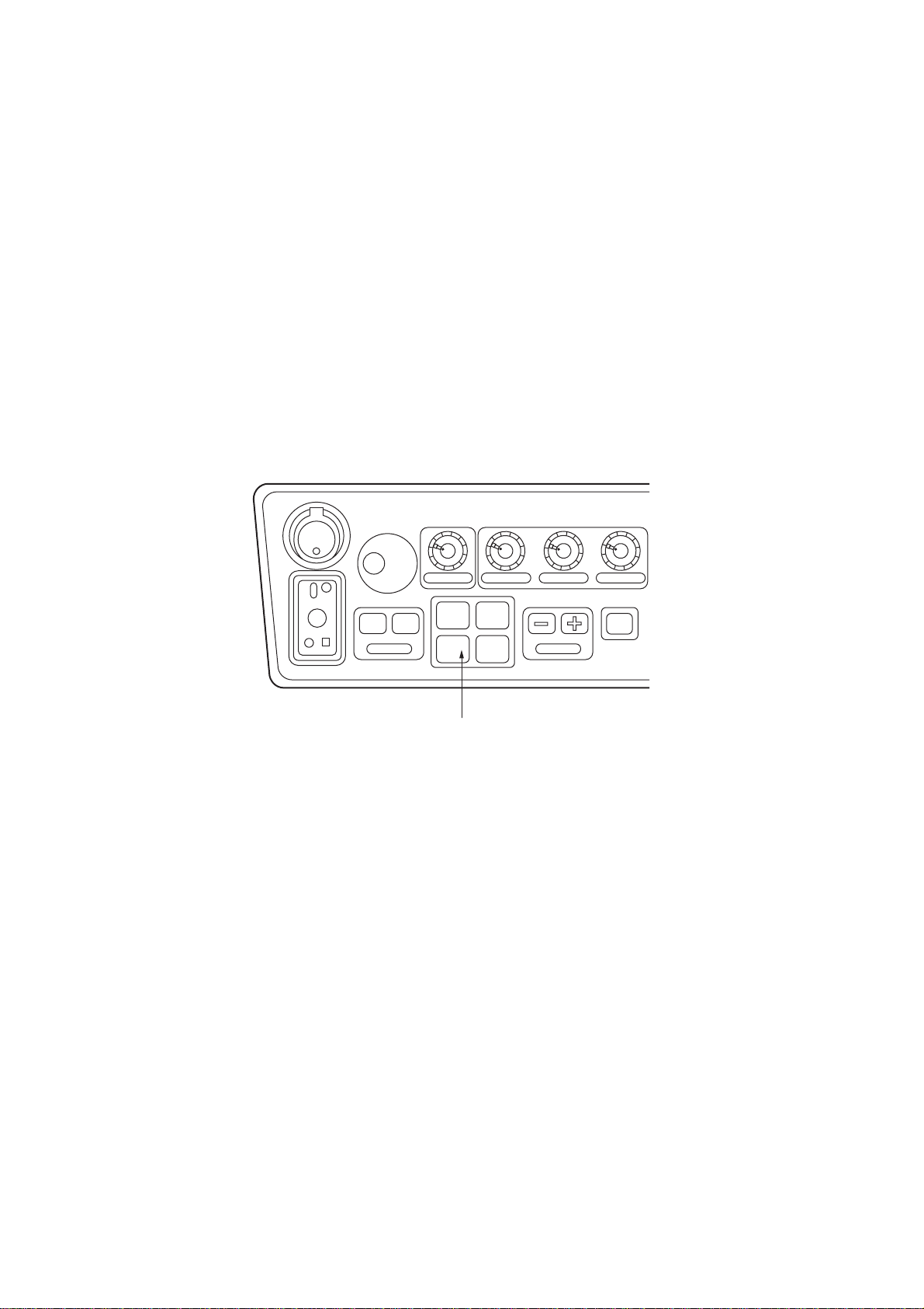
1.33 Function Keys
The four function keys (#1-4) on the control head serve for a macro function to instantly
select a combination of assigned functions or settings. The function keys provide optimum
radar settings for a specific purpose with a single key operation.
Each function key can be assigned a combination of particular radar settings that will be
most suited to your specific navigating purpose, and an adhesive label (such as BUOY,
HARBOR, COAST or the like) is usually attached to the key top for easy identification of
the assigned purpose.
The individual function keys are preset, or programmed, for the following purposes by
qualified service personnel at the time of installation using the procedures described in the
succeeding paragraphs:
Function keys #1, #2 and #3: Picture setup and specific operation
Function key #4: Specific operation or watch alarm
POWER
ON
PM
ANTENNA
TUNE
DEGAUSS ERR
BRILLIANCE
OFF ON
EBL
A/C RAIN A/C SEA GAIN
#1 #2
#3 #4
RANGE
STBY
TX
FUNCTION keys
#1: SET-UP 1
#2: SET-UP 2
#3: SET-UP 3
#4: SET-UP 4
Figure 1-42 Control head, function keys
1.33.1 Picture setup
Suppose that you have been navigating along a coast for hours and now you are approaching a harbor, your final destination. You will have to adjust your radar to change
from the settings for coastal navigation to those for harbor approach. Every time your
navigating environment or task changes, you must adjust the radar, which can be a nuisance in a busy situation. Instead of changing radar settings case by case, it is possible to
assign the function keys to provide optimum settings for often encountered situations.
The radar’s internal computer offers several picture setup options to be assigned to each
function key for your specific navigating requirements. For instance, one of the function
keys may be assigned the buoy detecting function and labeled BUOY on the key top. If
you press this key , the radar will be instantly set for optimum detection of navigation buoys
and similar objects and the label BUOY is shown at the left margin of the screen. If you repress the same key, the radar returns to the previous settings.
1-40
Page 52

The picture setup options assignable to any of the function keys are as shown in the table
below.
Table 1-2 Picture setup options
lebaLnoitpircseDlebaLnoitpircseD
YOUBgnitcetedrofgnittesmumitpO
slessevllams,syoubnoitagivan
stcejboecafrusllamsrehtodna
TROHSegnartrohsrofgnittesmumitpO
foelacsegnaragnisunoitceted
sselroMS3
GNISIURCfoelacsegnaragnisugnisiurcroF
regralroMS5.1
TSAOCagnisunoitagivanlatsaocroF
sselroMS21foelacsegnar
HGUOR
AES
niaryvaehro
PIHSgnitcetedrofgnittesmumitpO
slessev
GNOLegnargnolrofgnittesmumitpO
regralroMS6foelacs
ROBRAHegnartrohsrofgnittesmumitpO
AESagnisuegayovcinaecosnarT
rehtaewhguorrofgnittesmumitpO
REVIRnonoitagivanrofgnittesmumitpO
revira
agnisuaerarobrahaninoitagivan
sselroMS5.1foelacsegnar
regnolroMS21foelacsegnar
Each picture setup option defines a combination of several radar settings for achieving
optimum setup for a particular navigating situation. Those involved are interference rejector, echo stretch, echo average, automatic anti-clutter, pulselength and noise rejector settings.
Adjusting these features on a function key menu changes the original function key settings. To restore the original settings for a particular function key, it is necessary to display
the relevant function key menu and select appropriate menu options.
Note: Function key presetting requires a good knowledge of optimum radar settings. If
you want to change the original function key settings, consult your nearest FURUNO representative or dealer.
1.33.2 Specific operation
Most often used controls are placed on the center panel while less often used controls are
provided in the menu. To avoid opening the menus to set up the radar for a particular
situation, function keys #1, #2, #3 and #4 may be assigned a combination of the following
settings at the time of installation.
- Target trails (See paragraph 1.26.)
- Echo stretch 1,2 or 3 (See paragraph 1.23.)
- Pulsewidth 1 or 2 (See paragraph 1.12.)
- Echo averaging 1, 2 or 3 (See paragraph 1.24.)
- Echo color (See paragraph 1.32.)
- Panel illumination
- Marks brilliance
- Noise rejection
Provided that the function key is assigned the specific operation feature, press the key to
instantly set the radar for the preset purpose. The corresponding label will be displayed at
the left margin of the screen. If you re-press the function key, the radar returns to the
previous settings.
1-41
Page 53

1.33.3 W atch alarm
The watch alarm sounds an external buzzer at selected time intervals to help you keep
regular watch of the radar picture for safety or other purposes. This feature can be assigned to function key #4 with a choice of alarm intervals of 6, 10, 12, 15 and 20 minutes.
(See the flowchart on page 1-45 for sequence.)
Provided that function key #4 is assigned the watch alarm feature, just press function key
#4 to activate the feature. The label W ATCH appears at the lower-right corner of the screen
associated with a watch alarm timer counts down from the initial value (for example, “12:00”).
When a preset time interval has elapsed, an audible watch alarm is released and the label
WATCH turns red and the watch alarm timer freezes at “0:00.”
To silence the alarm, press the [AUDIO OFF] key . The label WA TCH turns to normal color
and the watch alarm timer is reset to the initial value and starts the count-down sequence
again.
If you press the [AUDIO OFF] key before the selected time interval is reached, the watch
alarm timer is reset to the initial value and starts the count-down sequence again.
1-42
Page 54

1.33.4 Setting for function keys #1/#2/#3
RADAR MENU
[FUNCTIONS (1)]
1 TARGET TRAILS
2 TARGET ALARM (1 or 2)
3 ORIGIN MARK (1 to 10)
4 INDEX LINES
5 ZOOM
6 PULSE WIDTH
7 INT REJECT
8 ARPA
9 VIDEO PLOT
0 [FUNCTIONS (2)]
[0]
[FUNCTIONS (2)]
1 [FUNCTIONS (1)]
2 BKGD COLOR
BLK (GRN CHAR)/
BLK (RED CHAR)/
BLU (ECHO AREA)
BLU/
BRT BLU
3 ECHO STRETCH OFF/1/2/3
4 ECHO AVERAGE OFF/1/2/3
5 ECHO COLOR YEL/GRN/COLOR
6 SHIP SPEED LOG/NAV/MAN
MAN = 00.0KT
(STW/SOG)
7 SET, DRIFT OFF/MAN
SET = 000.0°
DRIFT = 00.0KT
8 INDEX LINES NO.2 VRM/MAN
MAN = 00.00SM
9 [BRILLIANCE (1)]
0 [FUNCTIONS (3)]
[0]
[FUNCTIONS (3)]
1 [FUNCTIONS (2)]
2 [RADAR (1)]
3 [FUNCTION KEY 1]
4 [FUNCTION KEY 2]
5 [FUNCTION KEY 3]
6 [FUNCTION KEY 4]
7 RADAR1/2
8 INTER SWITCH
9 GYRO SETTING
EBL = xxx.x°
0 [FUNCTIONS (4)]
[3]
[3]
[FUNCTION KEY 1] (PICT)
1 [FUNCTIONS (3)]
2 FUNC KEY1 PICTURE/OPERATION
3 PICTURE FUNC1/BUOY/SHIP/
SHORT/LONG/CRUISING/
HARBOR/COAST/SEA/
ROUGH SEA/RIVER/BIRD
4 INT REJECT OFF/1/2/3
5 ECHO STRETCH OFF/1/2/3
6 ECHO AVERAGE OFF/1/2/3
7 A/C AUTO OFF/ON
8 [FUNC 1 PULSE WD]
9 NOISE REJECT OFF/ON
0 VIDEO CONTRAST 1/2/3
[8]
[FUNC 1 PULSE WD]
1 [FUNCTION KEY 1]
2 0.5 SM S1/S2
3 0.75 SM S1/S2/M1
4 1.5 SM S1/S2/M1
5 3 SM S2/M1/M2/M3
6 6 SM M1/M2/M3/L
7 12-24 SM M2/M3/L
[2] [2] to toggle between
OPERATION and PICTURE menu.
[FUNCTION KEY 1] (OPR)
1 [FUNCTIONS (3)]
2 FUNC KEY1 PICTURE/OPERATION
3 OPERATION
TARGET TRAILS/TARGET ALARM/ARPA/
VIDEO PLOT/ZOOM/
BKGD COLOR/INDEX LINES/
INT REJECT/2ND ECHO/ORIGIN MARK/
PLS WD 1/PLS WD 2/
ECHO STRETCH 1/2/3/
ECHO AVG 1/2/3/
ECHO COLOR/
CHAR BRILL/MARK BRILL/
TRAIL BRILL/RINGS BRILL/
EBL BRILL/VRM BRILL/
+CURSOR BRILL/HL BRILL/
PLOT BRILL/ L/L BRILL/
CHART BRILL/NOISE REJECT/
BARGE MK/
BARGE CONFIGURATION
Figure 1-43 Keying sequence for setting functions keys #1/#2/#3
1-43
Page 55

Picture setup default for function keys 1, 2 and 3
Table 1-3 Picture setup default for Function Keys 1, 2 and 3
TNI.4
REVIR21FFOFFOFFOS1S1S2S1M2M
YOUB323FFONO1S2S2S1M2ML
PIHS323FFONO1S2S2S1M2ML
TROHS2FFOFFOFFOFFO1S1S1S2S1M2M
GNOL323FFONO1S1S1S2S1M2M
GNISIURC3FFO3 FFONO2S2S2S2ML L
ROBRAH3FFOFFOFFOFFO1S1S1S2S1M2M
TSAOC3FFOFFOFFOFFO1S1S2S1ML L
NAECO2FFO3 FFOFFO1S2S2S1M2ML
AESHGUOR2FFO2 FFOFFO1S1S2S1M2ML
SE.5VAE.6C/A.7
TCEJER
OTUA
.JER
ESION.9
noL/P
MS5.0
noL/P
MS57.0
noL/P
MS5.1
noL/P
MS3
MS6
noL/P
noL/P
MS42-21
1-44
Page 56

1.33.5 Setting for function key #4
RADAR MENU
[FUNCTIONS (1)]
1 TARGET TRAILS
2 TARGET ALARM (1 or 2)
3 ORIGIN MARK (1 to 10)
4 INDEX LINES
5
6 PULSE WIDTH
7 INT REJECT
8 ARPA
9 VIDEO PLOT
0 [FUNCTIONS (2)]
[0]
[FUNCTIONS (2)]
1 [FUNCTIONS (1)]
2 BKGD COLOR
BLK (GRN CHAR)/
BLK (RED CHAR)/
BLU (ECHO AREA)
BLU/
BRT BLU
3 ECHO STRETCH OFF/1/2/3
4 ECHO AVERAGE OFF/1/2/3
5 ECHO COLOR YEL/GRN/COLOR
6 SHIP SPEED LOG/NAV/MAN
MAN = xx.xKT
(STW/SOG)
7 SET, DRIFT OFF/MAN
SET = 000.0°
DRIFT=00.0KT
8 INDEX LINES NO.2 VRM/MAN
MAN = 00.00SM
9 [BRILLIANCE (1)]
0 [FUNCTIONS (3)]
[0]
[FUNCTIONS (3)]
1 [FUNCTIONS (2)]
2 [RADAR (1)]
3 [FUNCTION KEY 1]
4 [FUNCTION KEY 2]
5 [FUNCTION KEY 3]
6 [FUNCTION KEY 4]
7 RADAR1/2
8 INTER SWITCH
9 GYRO SETTING
EBL = xxx.x°
0 [FUNCTIONS (4)]
[6]
[FUNCTION KEY 4] (OPR)
1 [FUNCTIONS (3)]
2 FUNC KEY4 OPERATION/WATCH/ALARM
3 OPERATION
TARGET TRAILS/TARGET ALARM/ARPA/
VIDEO PLOT/ZOOM/
BKGD COLOR/INDEX LINES/
INT REJECT/2ND ECHO/ORIGIN MARK/
PLS WD1/PLS WD 2/
ECHO STRETCH 1/ 2/ 3/
ECHO AVG 1/ 2 / 3/
ECHO COLOR/
CHAR BRILL/MARK BRILL/
TRAIL BRILL/RINGS BRILL/
EBL BRILL/VRM BRILL/
+CURSOR BRILL/HL BRILL/
PLOT BRILL/ L/L BRILL
CHART BRILL/ NOISE REJECT/
BARGE MK/
BARGE CONFIGURATION
Press [2] once or twice to toggle
between OPERATION and WATCH
[6]
1 [FUNCTIONS (3)]
2 FUNC KEY4 OPERATION/WATCH/ALARM
3 WATCH ALARM INTERVAL
6/10/12/15/20 MIN
ALARM followed by ENTER key.
[FUNCTION KEY 4] (WATCH ALARM)
Figure 1-44 Keying sequence for setting functions keys #4
1-45
Page 57

1.34 Barge Information
Do the following to display the barge information.
1. Press [RADAR MENU], [0], [0], [2], [0] and [0] to display the RADAR 3 menu.
2. Press the [2] key twice to select BARGE MK ON, followed by the [ENTER] key.
3. Press the [3] key to select BARGE SIZE and enter length and width of a barge, followed by the [ENTER] key.
4. Press the [4] key to display the BARGE INFORMATION menu.
5. Enter number of barges in first row, followed by the [ENTER] key.
6. Enter the number of barges for 2nd, 3rd, 4th and/or 5th row followed by the [ENTER]
key. The barge information appears on the radar display.
1.35 Radar Map
A radar map is a combination of map lines and symbols whereby the user can define and
input the navigation, route planning and monitoring data on the radar equipment. Map
lines are a navigational facility whereby the observer can define lines to indicate channels
or traffic separation schemes. Also called nav lines, these lines can be ground stabilized to
stop them drifting. (Definition in Annex C of IEC 60936-1 and IEC 60872-1)
In this series of radar, a radar map may contain 150 points of mark and line data on one
map. 10 maps can the memorized to facilitate the repeated use on the routine navigation
area.
The user can create a radar map on a real-time basis while using the radar for navigation
or at leisure time at anchor or while the radar is not being used. Place of a map can be
made for any waterways apart from the actual own ship location. The map data is stored
on the EEROM card which is mounted on the main processor board socket. When the
optional Video Plotter board RP-26 and RAM card are installed in the display unit, much
more data can be created and copied to another card.
1.35.1 General operation procedure
1. Press the [NAV MENU] key to show the NAV INFORMATION 1 menu.
2. Press the [2] key to select the SELECT NAVAID operation.
3. Press the [2] key again to select navigation data input device, followed by the [ENTER]
key .
4. Also, set other nav data parameters as appropriate.
5. Press the [NAV MENU] key to close the NAV INFORMATION menu.
1-46
Page 58

Notes on radar map operation
1) Own ship position display requires an input from radionavigational equipment such as
a GPS receiver in accordance with the data format as defined by IEC 61162-1.
2) Wind, water current, depth, water temperature are not displayed when relevant sensors are not fitted.
1.35.2 Making a radar map
1. Press the [NAV MENU] key to display the NAV INFORMATION 1 menu.
2. Press the [1] key to display the RADAR MAP menu.
3. Press the [2] key twice to set MAP ON, then press the [ENTER] key.
4. Press the [8] key to select the MAP DISP SELECT menu.
[MAP DISP SELECT]
1 [RADAR MAP]
2 DANGER HIGHLIGHT OFF/ON
3 COAST LINE OFF/ON
4 MARK OFF/ON
5 NAV LINE OFF/ON
6 PROHIBITED AREAS OFF/ON
7 BUOY OFF/ON
8 CONTOUR LINE OFF/ON
Figure 1-45 MAP DISP SELECT menu
5. Press appropriate numeric key twice to select ON, then press the [ENTER] key.
6. Press the [NAV MENU] key to close the menu.
Mark entry mode
Marks can be entered by cursor position, L/L position (manual entry), or own ship position.
1. Press the [NAV MENU] key to display the NAV INFORMATION 1 menu.
2. Press the [1] key to display the RADAR MAP menu.
3. Press the [6] key and further press the [6] key to select the entry mode; cursor, L/L or
own ship position.
4. Press the [ENTER] key followed by the [NAV MENU] key.
5. Press the [MARK] key to read the following legends.
1-47
Page 59
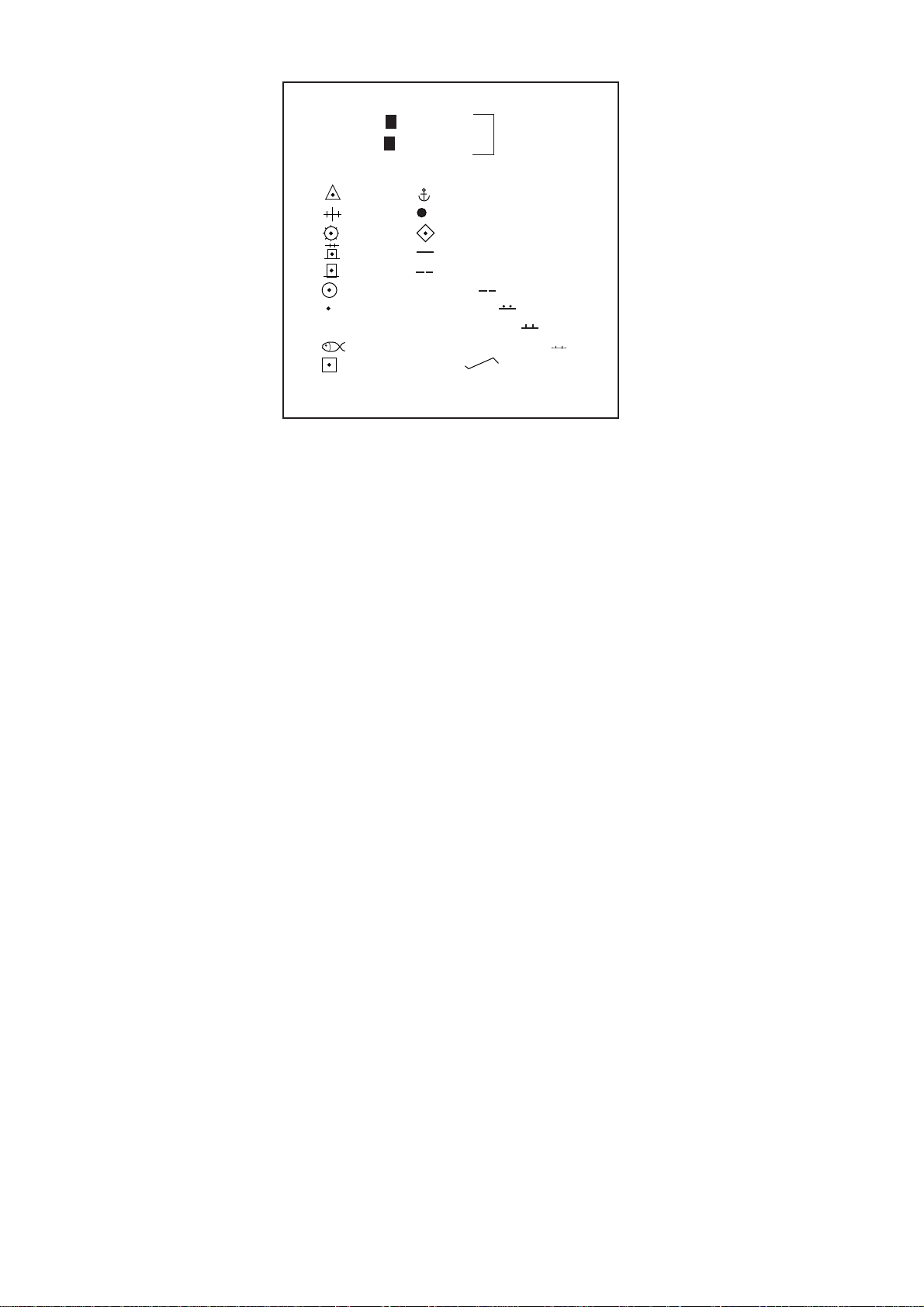
[ENTER MARK]
00°00.000 N/S 5-N 6-S
000°00.000 E/W 7-E 8-W
MARK 01
01 11 21 LINE CHANGE
02 12 22 MARK CANCEL
03 13
04 14
05 15
06 16 NAV LINE
07 17 COAST LINE
08 X 18 CONTOUR LINE
09 19 PROHIBITED AREAS
10 20 CABLE
CANCEL ENTER MARK: CANCEL KEY
* Appears when L/L mode is selected (step 3).
*
Figure 1-46 Marks for radar map
6. Select a wanted position, followed by the [ENTER] key. Positions can be selected
either by the Trackball, lat/lon values, or at own ship.
7. Select a desired mark by the corresponding number followed by the [ENTER] key.
8. Repeat steps 6-7. To enter the same mark selected, simply repeat step 6.
9. To erase a mark entered, enter 22, place the cursor to the mark you want to erase and
then press the [CANCEL] key.
10.To escape the mark entry mode, press the [CANCEL] key.
Example: How to draw a coastline
1. Press the [MARK] key.
2. Enter 17 to select COAST LINE and press the [ENTER] key.
3. Place the cursor mark on a required position and press the [ENTER] key.
4. Place the cursor at a next position and press the [ENTER] key. One line appears connecting designated two points.
5. Repeat step 4 to establish the coastline.
6. To enter more than one of the same type of line, after entering one line, enter 21 and
press the [ENTER] key. Then, repeat steps 2 to 5.
7. To draw other lines, enter line number (for example, 18 for contour line), followed by
the [ENTER] key. Repeat step 3.
8. To erase a line segment entered, enter 22, place the cursor to the point to erase and
then press the [CANCEL] key . For example, if point 4 is erased on the figure below , line
segment 3-4 is erased.
1-48
Page 60

1.35.3 Storing the map data
When you have made a map, store it with a map number as follows:
1. Press [NAV MENU], [1] to display the RADAR MAP menu.
2. Press the [7] key to show the ENTRY MAP menu.
3. Press the [2] key and enter map number by numeral key , followed by the [ENTER] key .
4. Press the [NAV MENU] key to leave this menu.
1.35.4 Displaying a radar map
1. Press [NAV MENU ], [1] to display the RADAR MAP.
2. Press the [3] key and enter the map number you want to display.
3. Press the [ENTER] key.
North marker
000
Separation zone
Target being tracked
290
280
300
310
320
330
340
350
010
020
030
W012
Heading marker
040
050
060
Waypoint
Navline
Own ship safe contour
070
Heading line
080
Planned route
270
260
090
100
Own ship vector
250
240
Dangerous side of own
ship safe contour may be
marked like this.
230
220
210
200
190
W011
180
170
140
150
160
120
130
Waypoint
110
Approximate coastline
Past position
ARPA: Equally time-spaced positions of any targets being tracked.
Note-not equally geographically spaced.
EPA: Past plot positions may not be equally time-spaced, up to the
operator.
Figure 1-47 Sample radar map
4. Press [1], [7] in that order to display the NAV LINE menu.
5. Press the [4] key twice to select NA V WIDTH ON and enter navigation width in nautical
mile.
6. Press the [ENTER] key followed by the [NAV MENU] key.
1-49
Page 61

1.35.5 Erasing contents of a radar map
1. Press [NAV MENU], [1] and [9] to display MAP ERASE menu.
[MAP ERASE]
1 [RADAR MAP]
2 DANGER HIGHLIGHT OFF/ALL
3 COAST LINE OFF/ALL
4 MARK OFF/ALL
5 NAV LINE OFF/ALL
6 PROHIBITED AREAS OFF/ALL
7 BUOY OFF/ALL
8 CONTOUR LINE OFF/ALL
Figure 1-48 MAP ERASE menu
2. Press a wanted number key twice to select ON or ALL, followed by the [ENTER] key.
3. Press the [NAV MENU] key to leave the menu.
1.36 Suppressing Second-trace Echoes
In certain situations, echoes from very distant targets may appear as false echoes (second-trace echoes) on the screen. This occurs when the return echo is received one transmission cycle later, that is, after a next radar pulse has been transmitted.
To activate or deactivate the second-trace echo rejector:
1. Press [RADAR MENU], [0], [0], [2] and [0] to show the RADAR 2 menu.
2. Press the [9] key to select 2ND ECHO.
3. Further press the [9] key to activate (ON) or deactivate (OFF) the second-trace echo
rejector.
4. Press the [ENTER] key to register your selection followed by the [RADAR MENU] key
to close the RADAR menu.
1.37 Displaying External Waypoint and Navigation
Line
Waypoint or navigation line defined on another navaid can be displayed by setting
WAYPOINT and NAV LINE menus as follows.
1. Press the [NAV MENU] key.
2. Press [8], [2] for waypoint or [7], [2] for navigation line if video plotter is not provided.
Note: When the waypoint is more than 5000 nm away from own ship, the data shows
“>*5000 nm”.
1-50
Page 62
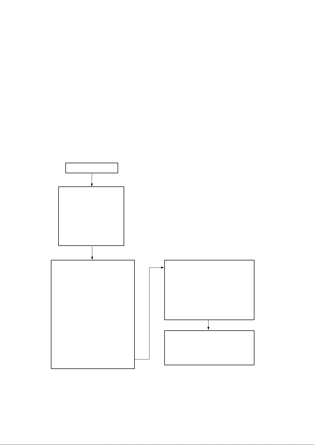
1.38 Adjusting Brilliance of Screen Data
You can adjust relative brilliance levels of various marks and alphanumeric readouts displayed on the screen by the steps below:
1. Press the [RADAR MENU] key to show the FUNCTIONS 1 menu.
2. Press the [0] and [9] keys to show the BRILLIANCE 1 menu. To display the BRILLIANCE 2 menu, further press the [0] key.
3. Select a desired menu item by pressing the corresponding numeric key. As an example, press [8] in the BRILLIANCE 1 menu if you want to change the brilliance of
target trails.
4. Further press the same numeric key as you pressed in step 3 above to select or highlight a desired brilliance level.
5. Press the [ENTER] key to conclude your selection followed by the [RADAR MENU] key
to close the menu.
RADAR MENU
[FUNCTIONS (1)]
1 TARGET TRAILS
2 TARGET ALARM (1 or 2)
3 ORIGIN MARK (1 to 10)
4 INDEX LINES
5 ZOOM
6 PULSE WIDTH
7 INT REJECT
8 ARPA
9 VIDEO PLOT
0 [FUNCTIONS (2)]
[0]
[FUNCTIONS (2)]
1 [FUNCTIONS (1)]
2 BKGD COLOR
BLK (GRN CHAR)/
BLK (RED CHAR)/
BLU (ECHO AREA)
BLU/
BRT BLU
3 ECHO STRETCH OFF/1/2/3
4 ECHO AVERAGE OFF/1/2/3
5 ECHO COLOR YEL/GRN/COLOR
6 SHIP SPEED LOG/NAVMAN
MAN = 00.0KT
(STW/SOG)
7 SET, DRIFT OFF/MAN
SET = 000.0°
DRIFT=00.0KT
8 INDEX LINES NO.2 VRM/MAN
MAN = 00.00NM
9 [BRILLIANCE (1)]
0 [FUNCTIONS (3)]
[9]
1 [FUNCTIONS (2)]
2 RINGS BRILL OFF/DIM/M1/M2/BRT
3 EBL BRILL DIM/M1/M2/BRT
4 VRM BRILL DIM/M1/M2/BRT
5 +CURSOR BRILL OFF/DIM/M1/M2/BRT
6 CHAR BRILL DIM/M1/M2/BRT
7 MARK BRIL DIM/M1/M2/BRT
8 TRAIL BRILL DIM/M1/M2/BRT
9 HL BRILL DIM/M/BRT
0 [BRILLIANCE (2)]
1 [BRILLIANCE (1)]
2 PLOT BRILL OFF/DIM/M1/M2/BRT
3 L/L GRID BRILL DIM/M1/M2/BRT
4 CHART BRILL DIM/M1/M2/BRT
5 SYMBOLS BRILL DIM/M1/M2/BRT
[BRILLIANCE (1)]
[0]
[BRILLIANCE (2)]
Figure 1-49 Sequence for selection of brilliance options
1-51
Page 63

The table below describes which menu item adjusts the brilliance of which picture element.
Table 1-4 Brilliance menu option and function adjusted
metIuneMsnoitcnuF
detsujda
SGNIRsgniregnardexiFLBEgniraebcinortcelE
MRVegnarelbairaV
dna1.oNsrekram
2.oN
RAHCciremunahplA
stuodaer
LIARTsliarttegraTLHdnaenilgnidaeH
TOLPdnaAPErofstolP
62-PRA
TRAHCstrahCSLOBMYSslobmystolP
L/LdnaedutitaL
metIuneMsnoitcnuF
detsujda
dna1.oNsenil
2.oN
ROSRUC+dellortnoc-llabkcarT
rosruc
KRAMelacsgniraeB
rekramnrets
senildirgedutignol
Note: You should adjust the entire CRT brilliance by operating the [BRILLIANCE] control
before adjusting the respective brilliance levels on the BRILLIANCE 1 and 2 menu.
1.39 Display of Wind/T ide/Depth/T ime
Wind
Wind, ocean current and depth sounding data can be displayed as follows:
1. Press the [NAV MENU] key to show the NAV INFORMATION 1 menu.
2. Press the [9] key twice to set WIND DATA ON and press the [ENTER] key.
3. Press the [0] key to show NAV INFORMATION 2 menu.
4. Press the [2] key twice to set WIND GRAPH ON and press the [ENTER] key.
Echo sounding depth and tide
1. Do the same to indicate ocean current graph and echo-sounding chart. Depth scales
can be selected among 10, 20, 50, 100, 200 and 500 m. The echogram shows the last
30 minutes of depths along the ship’s track.
2. Press the [NAV MENU] key followed by the [0] key to display the NAV INFORMATION
1 menu.
3. Press the [2] key to display WIND DATA ON and press the [ENTER] key.
4. Press the [5] key to display CURRENT GRAPH ON and press the [ENTER] key.
5. Press the [NAV MENU] key to close the NAV MENU.
1-52
Page 64

Note: Wind data and current data require appropriate sensors. The depth data requires
an adequate echo-sounding equipment. The echogram shows the last 30 minutes of depths
along the ship’s track. Wind vector shows a direction from which the wind blows in, relative
to own ship heading, and labeled T*. Wind velocity is a true wind speed as a result of
compensating for own ship’s speed and orientation. Ocean current (tide) is the direction to
which the current is flowing away from os position, relative to north.
* T in this case means a true value while T denotes “relative to True North” in the case of
EBLs and target ship vectors.
OS heading
NE
0
20
40
60
80
100 m
Current relative to north,
full scale 10 kt
Wind direction relative to
OS heading, full scale 100 kt.
WS
Wind velocity is calculated
value to exclude the ship's
orientation and speed.
Present depth
Last 30 minutes
of depth
30
20 10 min
(b) Depth Data
(a) Wind Data in Head-up Mode
Figure 1-50 Depth and wind data displays
1.40 Displaying the Rate-of-Turn Scale
If a rate-of-turn meter is connected to this radar, the rate-of-turn scale can be displayed at
the top of the radar screen.
1. Press the [NAV MENU] key.
2. Press the [0] key twice to display the NAV INFORMATION 3 menu.
3. Press the [8] key to select ROT SCALE.
4. Further press the [8] key to turn the rate-of-turn display on or off and select display
range (in degrees).
Rate-of-Turn Scale
010
SB
/MIN
AUTO TUNE
HDG 123.4°T GYRO
SPEED 14.8KT WT LOG
020
ANT1 MAIN
0.75
/0.25SM
+0.350SM
330.0° T
HEAD UP RM
2ND
340
P
350
0° 30° 60° 90°30°60°90°
000
Figure 1-51 Rate-of-turn scale
1-53
Page 65

1.41 Alarms
The table below summarizes alarms which may occur at various warning conditions.
Table 1-5 Alarms
tluaFmralaelbiduAmralalausiVsutatsmralatiuqoT
tegraTmrala
)ZAT(
mralahctaWspeeB00:0HCTAW
nol/talpihsnwO
nol/talrosruC
eruliafmetsySenoNLANGISGRB"egasseM
tcerrocnI
ekortsyek
speeB.sehsalftegraTsserPnoyek]2[
enoNnoitisoppihsnwoni"*.***"
snrut"HCTAW"lebalehT(
sezeerftnuocemitdnader
.)".00:0"ta
dleif
"*.***dleifnoitisoprosrucni"
tasraeppa"GNISSIM
radaroN.mottobbeercs
ERULIAFMETSYS.seohce
neercsfomottobtaderni
.tsetgnirud
enotpeebelbuoDenoNsiekortsyektcerroC
.unem1NOITCNUF
)12.1hpargaraP(
]FFOOIDUA[ehtsserP
yek. HCTAWlebalehT
dnaoedivlamronotsnrut
tesersiremiteht
1hpargaraP()3.33..
pihsnwotahterusekaM
morfdefsiatadnoitisop
vanoidarlanretxe
.tnempiuqe
annetnaehterusekaM
gninutehtnihctiws
.nositnemtrapmoc
peebelgnisaybdednopser
PEEBYEKtahtdedivorp
ehttadetcelessiNO
.unem2RADAR
eruliafgoLspeeb2,dernisraeppa".*.**GOL"
eruliafSFPEpeebsuounitnoCgninrawehtniderniSFPE
ehtesu,deliafsahgolehtfI
roftupnisilangisgolonfi
deepspihsehtelihwces03
.tk0.5nahteromneebsah
ehT.llecnoitacidnidna
sraeppaoslanoitacidni
siedomSPGehtnehw
dnaSPGneewtebdehctiws
.SPGD
ro,edomdeepSlaunaM
.rosnesetairporpparehto
sserp,peebehtecnelisoT
.yek]FFOOIDUA[eht
1-54
Page 66

Table 1-5 Alarms (con’t.)
tluaFmralaelbiduAmralalausiVsutatsmralatiuqoT
noitacidniGOS
NOISILLOC
ROTCEVEURT
noitacidni
TOLPETADPUenoNaretneotdeliafevahuoyfI
NOISILLOCpeebsuounitnoCni(nosemocNOISILLOC
enoN
peebsuounitnoC
enoNROTCEVEURTlebalehT
.sehsalf
.esruoc
deepS(GOSlebalehT
nehwdersnrut)dooGedaM
nodetcelessinoitpoGOS
ehtdnaunemeht
deepS(EMDSdetaicossa
gnirusaeMecnatsiDdna
)goldeeps=tnempiuqE
mottobatcetedotsliaf
nignitluser,deepsgnikcart
"retawhguorhtdeepS"eht
neercsehttadersnrut
eurTehtnehwretnec
ehtotsnruterdna,edom
ehtniroloctxetlamron
.edomMTpu-htroN
tolP.sehsalfnoitacidnisiht
oslategratfolobmys
-ATAro-APEnehw)der
.]6[
.yllacitamotuaedom)WTS(
MRehtnidetcelessirotceV
,nim01nihtiwtolpAPEtxen
noisillocnositegratdekcart
tonseodradarehT
otflestiteseryllacitamotua
neveatadGOSnaeviecer
asniagerEMDSehtfi
oT.deepsgnikcartmottob
sserp,noitacidniGOSesare
,]0[,]UNEMRADAR[syek
gnihsalfehteriuqca-eR
tievaeL.nim5nihtiwtegrat
.tnatropmitonsitifi
ronoitcaevisaveekaT
fognikcartdetanimret
lausiv,nehT.tegrat
.ffoseogsnoitacidni
mralAenoZdrauGpeebsuounitnoCdernisraeppaZGlebalehT
draugasretnetegratafi
ybdeksamsitegraT.enoz
.elgnairtdetrevnignihsalfa
mralATUOZGenoNneebsahelacsegnarehtfI
ehtfoenoekamotdecuder
5.1nahteromnoitisopsZG
,elacsegnarehtfosemit
sraeppaTUOZGlebaleht
.derni
.tegrat
.ZG
yek]FFOOIDUA[ehtsserP
gnidneffoegdelwonkcaot
foelacsegnarehtegnahC
1-55
Page 67

2. RADAR OBSERVATION
2.1 General
2.1.1 Minimum and maximum ranges
Minimum range
The minimum range is defined by the shortest distance at which, using a scale of 1.5 or
0.75 nm, a target having an echoing area of 10 m2 is still shown separate from the point
representing the antenna position.
It is mainly dependent on the pulselength, antenna height, and signal processing such as
main bang suppression and digital quantization. It is a good practice to use a shorter
range scale as far as it gives favorable definition or clarity of picture. The IMO Resolution
A. 477 (XII) and IEC 936 require the minimum range to be less than 50 m. All FURUNO
radars satisfy this requirement.
Maximum range
The maximum detecting range of the radar, Rmax, varies considerably depending on
several factors such as the height of the antenna above the waterline, the height of the
target above the sea, the size, shape and material of the target, and the atmospheric
conditions.
Under normal atmospheric conditions, the maximum range is equal to the radar horizon or
a little shorter. The radar horizon is longer than the optical one by about 6% because of the
diffraction property of the radar signal. The Rmax is given in the following equation.
R
= 2.2 x ( h1 + h2 )
max
where Rmax: radar horizon (nautical miles)
h1: antenna height (m)
h2: target height (m)
Radar horizon
Optical horizon
Figure 2-1 Radar horizon
For example, if the height of the antenna above the waterline is 9 meters and the height of
the target is 16 meters, the maximum radar range is;
R
= 2.2 x ( 9 + 16 ) = 2.2 x (3 + 4) = 15.4 nm
max
It should be noted that the detection range is reduced by precipitation (which absorbs the
radar signal).
2-1
Page 68

X-band and S-band
In fair weather, the above equation does not give a significant difference between X- and
S-band radars. However, in heavy precipitation condition, an S-band radar would have
better detection than an X-band radar.
2.1.2 Radar resolution
There are two important factors in radar resolution (discrimination): bearing resolution and
range resolution.
Bearing resolution
Bearing resolution is the ability of the radar to display as separate pips the echoes received from two targets which are at the same range and close together . It is proportional
to the antenna length and reciprocally proportional to the wavelength. The length of the
antenna radiator should be chosen for a bearing resolution better than 2.5° (IMO Resolution). This condition is normally satisfied with a radiator of 1.2 m (4 ft) or longer in the Xband. The S-band radar requires a radiator of about 12 feet (3.6 m) or longer.
Range resolution
Range resolution is the ability to display as separate pips the echoes received from two
targets which are on the same bearing and close to each other. This is determined by
pulselength only. Practically, a 0.08 microsecond pulse offers the discrimination better
than 35 m as do so with all FURUNO radars.
Test targets for determining the range and bearing resolution are radar reflectors having
an echoing area of 10 m2.
2.1.3 Bearing accuracy
One of the most important features of the radar is how accurately the bearing of a target
can be measured. The accuracy of bearing measurement basically depends on the narrowness of the radar beam. However, the bearing is usually taken relative to the ship’s
heading, and thus, proper adjustment of the heading line at installation is an important
factor in ensuring bearing accuracy. To minimize error when measuring the bearing of a
target, put the target echo at the extreme position on the screen by selecting a suitable
range.
2.1.4 Range measurement
Measurement of the range to a target is also a very important function of the radar . Generally , there are two means of measuring range: the fixed range rings and the variable range
marker (VRM). The fixed range rings appear on the screen with a predetermined interval
and provide a rough estimate of the range to a target. The variable range marker’s diameter is increased or decreased so that the marker touches the inner edge of the target,
allowing the operator to obtain more accurate range measurements.
2-2
Page 69

2.2 False Echoes
Occasionally echo signals appear on the screen at positions where there is no target or
disappear even if there are targets. They are, however, recognized if you understand the
reason why they are displayed. Typical false echoes are shown below.
2.2.1 Multiple echoes
Multiple echoes occur when a transmitted pulse returns from a solid object like a large
ship, bridge, or breakwater. A second, a third or more echoes may be observed on the
display at double, triple or other multiples of the actual range of the target as shown below.
Multiple reflection echoes can be reduced and often removed by decreasing the gain (sensitivity) or properly adjusting the [A/C SEA] control.
True
echo
Target
Own ship
Multiple
echo
Figure 2-2 Multiple echoes
2.2.2 Sidelobe echoes
Every time the radar pulse is transmitted, some radiation escapes on each side of the
beam, called “sidelobes.” If a target exists where it can be detected by the side lobes as
well as the main lobe, the side echoes may be represented on both sides of the true echo
at the same range. Sidelobes show usually only on short ranges and from strong targets.
They can be reduced through careful reduction of the gain or proper adjustment of the A/
C SEA control.
Target A
Target B
(Spurious)
Figure 2-3 Sidelobe echoes
Target B
(True)
2-3
Page 70

2.2.3 Virtual image
,
,
,
A relatively large target close to your ship may be represented at two positions on the
screen. One of them is the true echo directly reflected by the target and the other is a
false echo which is caused by the mirror effect of a large object on or close to your ship
as shown in the figure below. If your ship comes close to a large metal bridge, for example, such a false echo may temporarily be seen on the screen.
Target ship
Own
ship
True
echo
Mirror image
of target ship
False
echo
Figure 2-4 Virtual image
2.2.4 Shadow sectors
Funnels, stacks, masts, or derricks in the path of the antenna block the radar beam. If the
angle subtended at the antenna is more than a few degrees, a non-detecting sector may
be produced. Within this sector targets can not be detected.
Radar
antenna
Radar
mast
Shadow sector
Figure 2-5 Shadow sectors
2-4
Page 71

2.3 SART (Search and Rescue Transponder)
A Search and Rescue Transponder (SART) may be triggered by any X-Band (3 cm) radar
within a range of approximately 8 nm. Each radar pulse received causes it to transmit a
response which is swept repetitively across the complete radar frequency band. When
interrogated, it first sweeps rapidly (0.4 µs) through the band before beginning a relatively
slow sweep (7.5 µs) through the band back to the starting frequency. This process is
repeated for a total of twelve complete cycles. At some point in each sweep, the SART
frequency will match that of the interrogating radar and be within the pass band of the
radar receiver . If the SART is within range, the frequency match during each of the 12 slow
sweeps will produce a response on the radar display , thus a line of 12 dots equally spaced
by about 0.64 nautical miles will be shown.
When the range to the SART is reduced to about 1 nm, the radar display may show also
the 12 responses generated during the fast sweeps. These additional dot responses,
which also are equally spaced by 0.64 nm, will be interspersed with the original line of 12
dots. They will appear slightly weaker and smaller than the original dots.
Echo of SART
Position of
SART
Screen A: When SART
is distant
Radar antenna
beamwidth
24 NM
Own ship’s
position
9500 MHz
9200 MHz
7.5 µs
Sweep start
Low speed sweep signal
Screen B: When SART
is close
1.5 NM
Own ship’s
SART mark
length
Sweep time
95 µs
High speed sweep signal
position
Radar receiver
bandwidth
Lines of 12 dots
are displayed in
concentric arcs.
Echo of
SART
Position of
SART
Figure 2-6 Appearance of SART signal on the radar display
2.3.1 General procedure for detecting SART response
1. Use the range scale of 6 or 12 nm as the spacing between the SART responses is
about 0.6 nm (1125 m) to distinguish the SART.
2. Turn off the automatic clutter suppression.
3. Turn off the Interference Rejector.
4. Turn off the Echo Average.
2-5
Page 72

2.3.2 General remarks on receiving SART
SART range errors
When responses from only the 12 low frequency sweeps are visible (when the SART is at
a range greater than about 1 nm), the position at which the first dot is displayed may be as
much as 0.64 nm beyond the true position of the SART. When the range closes so that the
fast sweep responses are seen also, the first of these will be no more than 150 meters
beyond the true position.
Radar bandwidth
This is normally matched to the radar pulselength and is usually switched with the range
scale and the associated pulselength. Narrow bandwidths of 3-5 MHz are used with long
pulses on long range and wide bandwidths of 10-25 MHz with short pulses on short ranges.
Any radar bandwidth of less than 5 MHz will attenuate the SART signal slightly, so it is
preferable to use a medium bandwidth to ensure optimum detection of the SART.
Radar side lobes
As the SART is approached, sidelobes from the radar antenna may show the SART responses as a series of arcs or concentric rings. These can be removed by the use of the
anti-clutter sea control although it may be operationally useful to observe the sidelobes as
they may be easier to detect in clutter conditions and also they will confirm that the SART
is near to the ship.
Gain
For maximum range SART detection the normal gain setting for long range detection
should be used, that is, with background noise speckle visible.
A/C SEA control
For optimum range SART detection, this control should be set to the minimum. Care should
be exercised as wanted target in sea clutter may be obscured. Note also that in clutter
conditions the first few dots of the SART response may not be detectable, irrespective of
the setting of the anti-clutter sea control. In this case, the position of the SART may be
estimated by measuring 9.5 nm miles from the furthest dot back towards own ship.
Some sets have automatic/manual anti-clutter sea control facilities in which case the operator should switch to manual.
2-6
Page 73

A/C RAIN control
This should be used normally (to break up areas of rain) when trying to detect a SART
response which, being a series of dots, is not affected by the action of the anti-clutter rain
circuitry. Note that Racon responses, which are often in the form of a long flash, will be
affected by the use of this control.
Some sets have automatic/manual anti-clutter rain control facilities in which case the
operator should switch to manual.
Note: This SART information is excerpted from IMO SN/Circ 197 Operation of Marine
Radar for SART Detection.
2.4 RACON (Radar Beacon)
A racon is a radar transponder which emits a characteristic signal when triggered by a
ship’s radar (usually only the 3 centimeter band). The signal may be emitted on the same
frequency as that of the triggering radar, in which case it is superimposed on the ship's
radar display automatically.
The racon signal appears on the PPI as a radial line originating at a point just beyond the
position of the radar beacon or as a Morse code signal (figure below) displayed radially
from just beyond the beacon.
Racon
Figure 2-9 Appearance of RACON signal on the radar display
2-7
Page 74

3. MAINTENANCE
Periodic checks and maintenance are important for proper operation of any electronic
systems. This chapter contains maintenance instructions to be followed to obtain optimum
performance and the longest possible life of the equipment.
WARNING
Do not open the equipment.
Hazardous voltage which can
cause electrical shock exists
inside the equipment. Only
qualified personnel should
work inside the equipment.
Turn off the radar power
switch before servicing the
antenna unit. Post a warning sign near the switch
indicating it should not be
turned on while the antenna
unit is being serviced.
Prevent the potential risk of
being struck by the rotating
antenna and exposure to
RF radiation hazard.
POWER Switch in AC
Powered Display Unit
FOR TECHNICIANS
The display unit designed to run on AC
power has a power switch inside its
base which cuts off 100/200 VAC power
to the display unit. Pull the display unit
forward several centimeters to access
the switch. TURN THE SWITCH OFF
(as well as the main POWER switch)
WHENEVER ACCESSING INSIDE THE
DISPLAY UNIT.
POWER Switch
J106
J105
J104
J103
Wear a safety belt and hard
hat when working on the
antenna unit.
Serious injury or death can
result if someone falls from
the radar antenna mast.
J446
J466
J462
J465
Display unit, inside view
3-1
Page 75
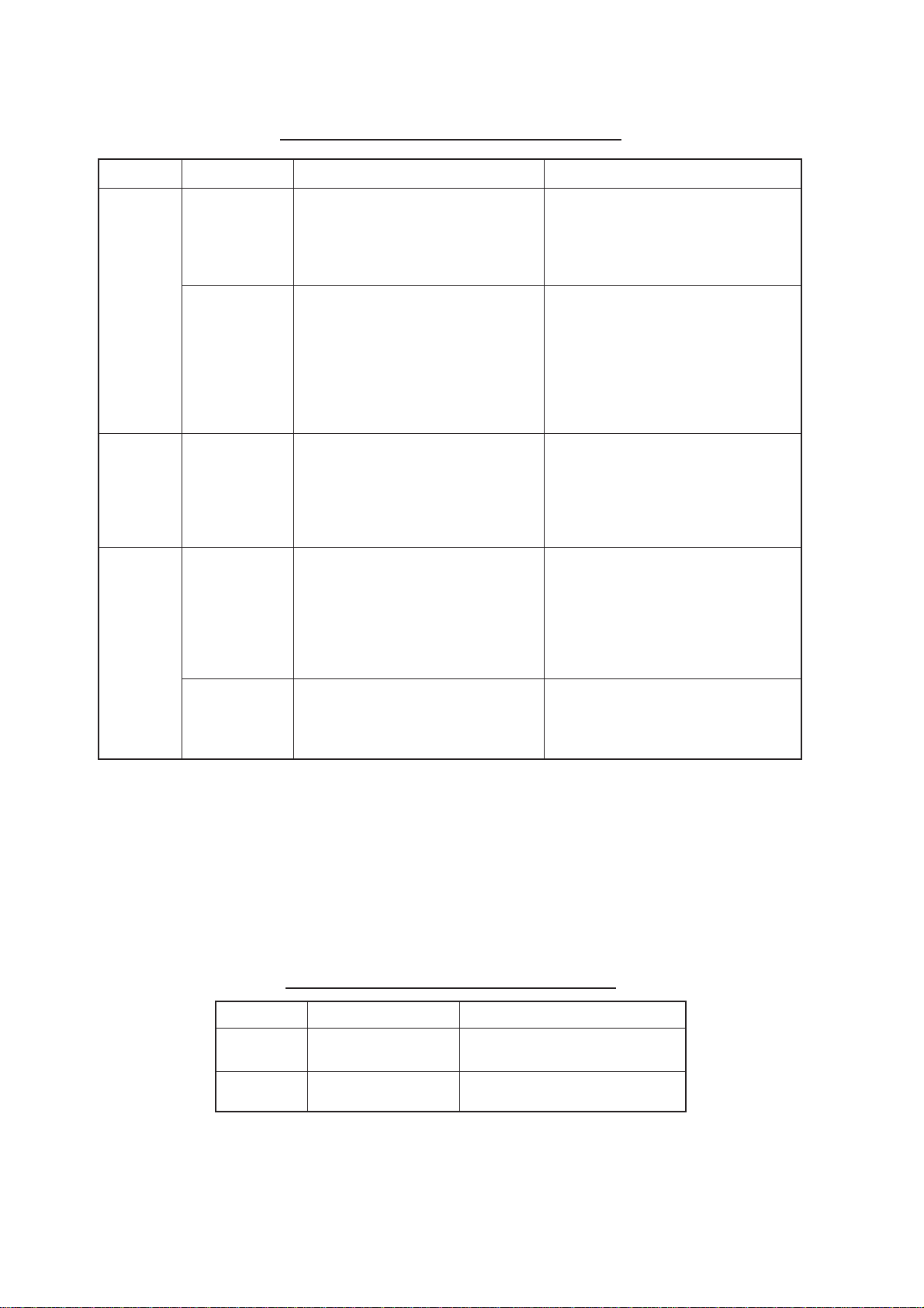
3.1 Periodic Maintenance Schedule
Table 3-1 Periodic maintenance schedule
lavretnItniopkcehCserusaemdnakcehCskrameR
6ot3
shtnom
-ilauqrof(
-hcetdeif
snaicin
)ylno
6ot3
shtnom
-ilauqrof(
-hcetdeif
snaicin
)ylno
shtnom6
enoot
raey
-ilauqrof(
-hcetdeif
snaicin
)ylno
stundesopxE
nostlobdna
tinuannetna
annetnA
rotaidar
lanimreT
dnaspirts
nisgulp
annetnatinu
dnaTRC
gnidnuorrus
stnenopmoc
.stnenopmoc
denesoolrodedorrocrofkcehC
naelc,yrassecenfI.stlobdnastun
ecalpeR.ylkcihtmehttniaperdna
.dedorrocylivaehfimeht
noskcarcdnatridrofkcehC
dluohstridkcihT.ecafrusrotaidar
htolctfoshtiwffodepiweb
afi.retawhserfhtiwdenepmad
thgilsaylppa,dnuofsikcarc
rodnuopmocgnilaesfotnuoma
,ydemeryraropmetasaevisehda
.riaperrofllacneht
kcehcotrevocannetnanepO
gulpdnapirtslanimret
kcehcoslA.edisnisnoitcennoc
annetnafoteksagrebbureht
.noitaroiretedrofsrevoc
dnaTRCtaegatlovhgiH
tcarttastnenopmocgnidnuorrus
lliwhcihwtnemnorivnenitsud
aksA.noitalusniroopesuac
egatlov-hgihlanretninaelcot
.tinu
relaedroevitatneserperONURUF
desuebyamdnuopmocgnilaeS
llamsaylppA.tniapfodaetsni
stunneewtebesaergfotnuoma
nilavomerysaerofstlobdna
.erutuf
tnevloscitsalpesutonoD
deenuoyfI.gninaelcrof)enoteca(
,tinuannetnamorfecievomerot
citsalproremmahnedoowaesu
tinuehtnokcarC.remmahdaeh
gnisuac,ssergniretawesuacyam
lanretniotsegamadsuoires
.stiucric
nisrevocannetnagnisolcnehW
hctacottonluferaceb,noitisop
dnasrevocneewtebseriwesool
eriwropacrebburedonaTRCfI
.tiecalper,dekcarcsihtaehs
:naicinhcetecivresroF tatiaW
egatlovhgihlitnusetunim3tsael
VHdnaTRC(stnenopmoc
laudiserriehtegrahcsid)sroticapac
.mehtgnisseccaerofebsegrahc
lanimreT
,spirts
lanimret
htrae,stekcos
.cte,gnitaesreporp
.snoitcennocesoolrofkcehC
rofsgulpdnastcatnockcehC
3.2 Life Expectancy of Major Parts
The hours shown in the table below are the average usage times for ocean-going ships.
When the radar is mainly used for detection of small targets on long ranges the usage
times will be lower than shown.
Table 3-2 Life expectancy of major parts
traPepyTycnatcepxEefiL
annetnA
rotom
nortengaMWk52,6345-GMsruoh000,3ot000,2
mpr84,175-G8D
mpr42,175-G8D
sruoh000,01nahteromsraeG
3-2
Page 76

3.3 Replacement of Battery
A battery installed on the RP Board or GYRO CONVER TER Board inside the display unit
helps preserve the data when the power is turned off. The life of the battery is about five
years.
When the battery voltage is low, NG appears at diagnostic test for RP board. Contact your
dealer for replacement.
Table 3-3 Battery ordering information
BCP
emaN
draoBPRS3RE957-721-000
draoBCGL.82/1RC967-301-000
yrettaB
epyT
edoC
rebmun
3-3
Page 77
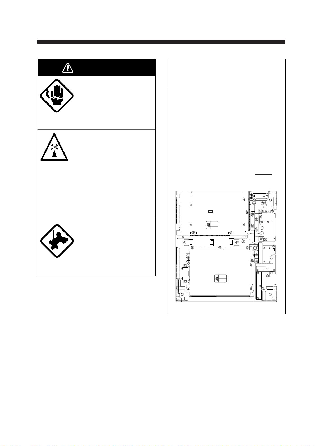
4. TROUBLESHOOTING
WARNING
Do not open the equipment.
Hazardous voltage which can
cause electrical shock exists
inside the equipment. Only
qualified personnel should
work inside the equipment.
Turn off the radar power
switch before servicing the
antenna unit. Post a warning sign near the switch
indicating it should not be
turned on while the antenna
unit is being serviced.
Prevent the potential risk of
being struck by the rotating
antenna and exposure to
RF radiation hazard.
POWER Switch in AC
Powered Display Unit
FOR TECHNICIANS
The display unit designed to run on AC
power has a power switch inside its
base which cuts off 100/200 VAC power
to the display unit. Pull the display unit
forward several centimeters to access
the switch. TURN THE SWITCH OFF
(as well as the main POWER switch)
WHENEVER ACCESSING INSIDE THE
DISPLAY UNIT.
POWER Switch
J106
J105
J104
J103
Wear a safety belt and hard
hat when working on the
antenna unit.
Serious injury or death can
result if someone falls from
the radar antenna mast.
J446
J466
J462
J465
Display unit, inside view
4-1
Page 78

4.1 Easy Troubleshooting
This section provides easy troubleshooting for the user.
Table 4-1 Easy troubleshooting
melborPydemeR
krampihsnwooNre unembusENIL/KRAMehttadetcelessiNOKRAMSOtahtkcehC
,htdiw,htgnel(noitamrofnipihsnwo,oslA.unemREHTOehtni
atlusnoC.sgnitteslaitininideretneneebevahdluohs).cte
.sliatedrofrelaedroevitatneserperONURUF
4.2 Advanced-level Troubleshooting
This paragraph provides information for the service technician to cure hardware and software problems. (This radar equipment contains complex modules in which fault diagnosis
and repair down to component level are not possible by users.)
Table 4-2 Advanced-level troubleshooting table
melborPdnatniopkcehC
radartubnodenrutrewoP
.llataetarepotonseod
tonsilenaplortnoC
.rehtiedetanimulli
tubdetsujdaecnaillirbTRC
erutcipon
annetnAgnitatortonmsinahcemevirdannetnA.1
ydemeR
esuacelbaborp
2Fro1FesufnwolB.1
ytiralop/egatlovsniaM.2
draoBylppuSrewoP.3
spmalnoitanimullI.4
sgnittesunem3/2//1RADAR.1
egatlovTRC.2
draoBUPS.3
GRBegassemehttahteton(
nisraeppaGNISSIMGIS
)YB-TS
evirdannetnaevitcefeD.2
yalerlamreht(yalerrotom
001/044,083/022/002,2K
)CAV
draoB0719-TNI.3
.egatlov
.unem
.eractsomtu
.msinahcem
.esufnwolbecalpeR.1
tupnidnasgniriwtcerroC.2
.draoBylppuSrewoPecalpeR.3
.spmalevitcefedecalpeR.4
-llatsniyalpsidelgnisfoesacnI.1
-retniradartuohtiw(noita
1RADARerusekam,)gnihctiws
3SNOITCNUFnodetcelessi
htiwylppusegatlovhgihkcehC.2
.draoBUPSecalpeR.3
evirdrennacskcehC.1
.nottubteseryalersserP.2
.nosihctiwsannetnatahtkcehC.3
4-2
Page 79

Table 4-2 Advanced-level troubleshooting table (con’t.)
melborPdnatniopkcehC
dnaatadciremunahplA
nideyalpsidtoneraskram
.sutatstimsnarT
htiwlortnoc]NIAG[tsujdA
tateslortnoc]AESC/A[
sdnegel,skraM.muminim
ontubraeppaesiondna
,kaelnoissimsnarT(.ohce
pihsnwognitneserper
).tnesbasi,noitisop
detadputonerutciProtareneGlangiSgniraeB.1
fonoitatneirotcerrocnI
erutcip
detsujdayllaunamgninuT
ytivitisnesrooptub
ydemeR
esuacelbaborp
draoBUPS.1.draoBUPSecalpeR.1
nortengaM.1
draoBrotaludoM.2
draoBUPS.3
)tinuannetna(draoB
draoBUPS.2
pukcoloediV.3
draoBUPS.1
ecafretnIoryG.2
nortengamdetaroireteD.1
CIMdenuteD.2
ecafrotaidarnotriD.3
sinoitcejerecartdnoceS.4
.NO
.elbac
.yb-dnatsgnirud
.denuteb
.tnerrucnortengamkcehC.1
.draoBrotaludoMecalpeR.2
.draoBUPSecalpeR.3
langisfonoitcennocehtkcehC.1
.draoBUPSecalpeR.2
.radarnodnaffonruT.3
LANGISGDH"egassemehT.1
ehtnehwsraeppa"GNISSIM
deviecertonsieslupgnidaeh
.ecafretniorygecalpeR.2
mn84ehtnognittimsnarT.1
nortengamkcehc,egnar
lamronwolebsitnerrucfI.tnerruc
ebyamnortengam,eulav
.nortengamecalpeR.evitcefed
tifI.tnerrucgnitcetedCIMkcehC.2
yamCIM,eulavlamronwolebsi
tsumCIM.denutedemocebevah
.ecafrusrotaidarnaelC.3
rotcejerecart-dnocesehtelbasiD.4
.63.1hpargarapotgnirrefer
radartubdegnahcegnaR
egnahctonseoderutcip
draoBUPS.2
draoBrehtoM.3
pukcoloediV.4
rotcejerecnerefretnI
ecnerefretni(elbareponi
)deyalpsidtonlevelnoitcejer
evitceffenihctertsohcE
si"2SE"ron"1SE"rehtieN(
).deyalpsid
senilxednilellarap2ylnO
)detnawsenil6(
draoBUPS.1
draoBrehtoM.2
draoBUPS.1.draoBUPSecalpeR.1
lavretnienil
yekEGNARevitcefeD.1
.deriuqereb
xednifognittestcerrocnI.1
EGNAR]-[dna]+[tihotyrT.1
-sseccusnufI.semitlarevessyek
yamdapyekfotnemecalper,luf
.draoBUPSecalpeR.2
.draoBrehtoMecalpeR.3
.radarnodnaffonruT.4
.draoBUPSecalpeR.1
.draoBrehtoMecalpeR.2
lavretnienilxednilellarapteS.1
.72.1hpargarapotgnirrefer
4-3
Page 80

Table 4-2 Advanced-level troubleshooting table (con’t.)
melborPdnatniopkcehC
tonerasgniregnaR
.deyalpsid
egnartanoitanimircsidrooPtonlortnocrettulcaeS.1
tonnoitatneserpnoitomeurT
.yltcerrocgnikrow
yltcerrocdekcarttontegraTnistegratfonoitinifedrooP.1
ydemeR
esuacelbaborp
foecnaillirbehttsujdA.1
1LLIRBnosgniregnar
.unem
draoBUPS.2
.ylreporpgninoitcnuf
]EDOM[fotcatnocrooP.1
.yek
.desseccatonsinoitceleS.2
.tcerrocnisiyrtnedeepS.3
etaruccaniyalpsidMT.4
rettulcaes
.lufsseccusnufi
.draoBUPSecalpeR.2
foycneuqerfetaruccani
.rotallicsolatsyrc
.redrahelttila
.sraeppa
dna]AESC/A[tsujdA.1
draobtiucricdetaicossaecalpeR.1
]AESC/A[fognittesreporpmI.1
ylnoneessirettulcaesfI.lortnoc
tcepsus,egnaresolcyrevta
yek]EDOM[ehtsserpotyrT.1
"MT"litnuyek]EDOM[ehtsserP.2
deepspihsnwotcerrocretnE.3
.9.1hpargarapotgnirrefer
dnadeepstahterusekaM.4
.etaruccaerastupnissapmoc
otgnirreferslortnoc]NIARC/A[
.51.1dna41.1shpargarap
4.3 Diagnostic Test
A diagnostic test program is provided to enable testing of major circuit boards in the radar
display unit. Note that the normal radar picture is lost during this test.
Proceed as follows to execute the diagnostic test:
1. Press the [RADAR MENU] key to show the FUNCTIONS 1 menu.
2. Press the [0] key three times to show the FUNCTIONS 4 menu.
3. Press the [3] key to select menu item TEST. Then, press the [ENTER] key.
Program numbers appear. The diagnostic test is executed and the screen shows test
results as shown on the next page. OKs appear for normal operation. If NG (No good)
appears, corresponding components may be defective. Consult your dealer.
4. Small squares displayed at the right bottom of the test result screen are for testing the
control and keys on the control head. As you operate these controls and keys, corresponding squares are highlighted, indicating that your control/key operations are properly recognized.
5. To terminate the diagnostic test, press [STBY/TX] key once or twice.
4-4
Page 81

[RADAR MENU] key
[FUNCTIONS (1)]
1 TARGET TRAILS
2 TARGET ALARM (1 or 2)
3 ORIGIN MARK (1 to 10)
4 INDEX LINES
5 ZOOM
6 PULSE WIDTH
7 INT REJECT
8 ARPA
9 VIDEO PLOT
0 [FUNCTIONS (2)]
[0] key
[FUNCTIONS (2)]
1 [FUNCTIONS (1)]
2 BKGD COLOR BLK(GRN CHAR)/
BLK(RED CHAR)/
BLU (ECHO AREA)
BLU/
BRT BLU
3 ECHO STRETCH OFF/1/2/3
4 ECHO AVERAGE OFF/1/2/3
5 ECHO COLOR YEL/GRN/COLOR
6 SHIP SPEED LOG/NAV/MAN
MAN = 00.0KT
(STW/SOG)
7 SET, DRIFT OFF/MAN
SET = 000.0°
DRIFT = 00.0KT
8 INDEX LINES NO. 2 VRM/MAN
9 [BRILLIANCE (1)]
0 [FUNCTIONS (3)]
MAN = 00.00NM
[0] key
[FUNCTIONS (3)]
1 [FUNCTIONS (2)]
2 [RADAR (1)]
3 [FUNCTION KEY 1]
4 [FUNCTION KEY 2]
5 [FUNCTION KEY 3]
6 [FUNCTION KEY 4]
7 RADAR 1/2
8 INTER SWITCH
9 GYRO SETTING
0 [FUNCTIONS (4)]
[0] key
[FUNCTIONS (4)]
1 [FUNCTIONS (3)]
2
3 TEST
Figure 4-1 Keying sequence for diagnostic test
4-5
Page 82

The test program checks the logic boards and the keyboard. The squares represent the
corresponding keypads. Numerals indicate the position of the controls under check.
SPU Board
(03P9253)
Program No.
ARP Board
(18P9002)
Program No.
RP Board
(14P0298)
Program No.
** = Program
Version No.
ROM test
RAM test
FR-2105V TEST
PROGRAM NO ROM RAM CRAM DIPSW
MAIN 03591570** OK OK
ARP 18590381** OK OK OK 1101
DSP 18590391** OK OK OK
RP 03590941** OK OK OK 1111
Performance monitor and
degauss switches check
Key and control check
(BRILLIANCE, A/C RAIN, A/C SEA, GAIN cannot be checked.)
DRAM OK
RP BOARD BAT OK
RP CARD 1 OK CARD 2 OK
CARD 1 BAT OK CARD2 BAT OK
ANTENNA SPEED 23.8RPM
TRIG FREQ. 1005Hz
MAG CURRENT 11.1V
R. MONITOR 1.8V
TUNE IND. 0.8V
000
000
EBL check
(Rightward increases;
leftward decreases)
VRM check
(Rightward increases;
leftward decreases)
CRAM test
DIP SW (S1) No.
1234
No.1 at left
ARP Board 18P9002's
DIP SW (S1) setting
0: ON
1: OFF
RP Board 14P0298's
DIP SW (S1) setting
0: ON
1: OFF
To escape from diagnostic
test, press STBY/TX key
twice.
000
000
Trackball check
• Up movement and indication:
Rightward increases; leftward
decreases.
• Down movement and indication:
Upward increases, downward
decreases.
Figure 4-2 Diagnostic test results
Test pattern
A test pattern may be overlaid on the test results display by pressing the [STBY/TX] key
once at the test results display.
4-6
Page 83

5. ARPA ARP-26 (Option for NM-type radar)
5.1 General
This radar can accommodate an ARPA (Automatic Radar Plotting Aid) module ARP-26
complying with IMO A.823 and IEC 60987-1. This chapter describes the operation of the
ARPA. For operation of normal radar, refer to Chapter 1.
Note: ARP-26 is not available with statute mile (SM)-type radar.
5.1.2 Principal specifications
Acquisition and tracking
• Automatic acquisition of up to 20 targets plus manual acquisition of 10 targets, or fully
manual acquisition of 30 targets between 0.2 and 32 nm. Manual acquisition has priority over automatic acquisition. Therefore, if 20 targets have been manually acquired,
the capacity for automatic acquisition is 10 targets.
• The ARPA automatically tracks all acquired targets, whether manually or automatically
acquired, between 0.1 and 32 nm (0.1 and 24 nm depending on initial setting). Manually acquired targets are indicated in bold symbols and the automatically acquired targets, in thinner symbols.
Vector length: 0.5, 1, 2, 3, 6, 12, 15, 30 minutes
Orientation: True velocity or relative velocity
Stabilization: Sea or Ground as selected with the [VECTOR] key.
Motion trend: Displayed within 20 scans, full accuracy within 60 scans after acquisi-
tion.
Past positions: Choice of 5, 10 or 20 past positions at intervals of 30 seconds, 1, 2, 3 or
6 minutes.
Alarms: Visual and audible alarms against targets violating CPA/TCPA limits,
lost targets, targets crossing guard zone, system failure and target full
status.
Trial maneuver: Predicted situation appears after selected delay (1-60 minutes).
5-1
Page 84

5.2 Controls for ARPA
The ARPA uses the keys on the plotting keyboard on the right side of the control head.
PLOT MENU: Shows/hides ARP A menus.
Plot Symbol keys: Select specific plot symbols for manually acquired targets.
TARGET CANCEL: Terminates tracking of a single target specified by the trackball if the
key is pressed with a hit-and-release action. If the key is held depressed for about 3
seconds, tracking of all targets is terminated.
ENTER: Registers menu options selected.
VECTOR: Selects true or relative presentation of target vectors.
TARGET DATA: Displays data on one of tracked targets selected by the trackball.
LOST TARGET: Silences the lost target aural alarm and erases the lost target symbol.
ACQ: Manually acquires a target.
AUDIO OFF: Silences aural alarm.
HL
PANEL
MODE
LOST
TARGET
MARK
A/C
AUTO
ENTER
AUDIO
OFF
3
6
ACQ
TARGET
9
DATA
TARGET
CANCEL
OFF
OFF
CENTER
EBL
TARGET
TRAILS
CANCEL
BRILL
2
1
VECTOR
4
5
CHART
ALIGN
7
8
CU, TM
RESET
0
Figure 5-1 Plotting keypad
5.3 ARPA Menu Operation
5.3.1 Activating the ARPA function
1. Press the [RADAR MENU] key.
RADAR
MENU
PLOT
MENU
NAV
MENU
2. Press the [8] key to select ARPA, instead of EPA. (The label ARPA appears at the
screen center .)
5-2
Page 85

5.3.2 Setting ARP A parameters
Various parameters for the ARPA are set on the ARPA 1 and ARPA 2 menus. To do this,
follow the steps shown below:
1. Press the [PLOT MENU] key to show the ARPA 1 menu.
2. Press the [0] key once if you wish to go to the ARPA 2 menu.
3. Select a desired menu item by pressing the corresponding numeric key.
4. Select a menu option by pressing the same numeric key as pressed in step 3 above. If
there is more than one option on the current menu item, you may need to press the
numeric key several times. Press it until the desired option is highlighted. (Note that
certain menu items will prompt you to enter numeric data or to define points on the
radar screen with the trackball.)
5. Press the [ENTER] key to register settings.
6. Press the [PLOT MENU] key to close the menu.
[ARPA (1)]
1 VECTOR TIME 30SEC/1/2/3/6/12/15/30MIN
2 AUTO ACQ OFF/ON
3 AUTO ACQ AREA 3.6/[SET]*
4 GUARD ZONE OFF/ON
5 [GUARD ZONE SET] **
6 TARGET BASED SPEED
7 REFERENCE TARGET VECT OFF/ON
8 COLLISION ALARM CPA 0.0KT
TCPA 00.0MIN
9 [TRIAL MANEUVER]
0 [ARPA (2)]
[0] key * Set opens the [AUTO ACQ AREA SET]
[ARPA (2)]
1 [ARPA (1)]
2 TRIAL MODE STATIC/DYNAMIC
3 HISTORY OFF/ON
4 HISTORY POINTS 5/10/20
5 HISTORY INTERVAL 30SEC/1/2/3/6MIN
6 MARK SIZE STD/LARGE
7 GUARD, ACQ STABILIZE NORTH/CRT
8 [INPUT SIG CHECK (1)]
9 [ARPA TRACK TEST]
0
Figure 5-2 Sequence for setting up ARPA
sub menu which reads:
1 [ARPA (1)]
2 1/2 SET LEFT/RIGHT BOUNDARY
CANCEL PREVIOUS AREA: CANCEL
KEY
** This sub menu reads:
(GUARD ZONE SET]
1 [ARPA (1)]
2 1/2 SET LEFT/RIGHT BOUNDARY
CANCEL PREVIOUS AREA: CANCEL
KEY
5-3
Page 86

5.4 Start-up Procedure
The ARPA requires own ship’s speed input and heading data. The speed can be entered
automatically from a speed log (SDME, Speed and Distance Measuring Equipment), navaid,
or by referencing to a target-based speed (based on three max. stationary objects). Manual
input is also possible.
5.4.1 Automatic speed input
For speed log input:
1. Press the [RADAR MENU] key and the [0] key to show the FUNCTIONS 2 menu.
[RADAR MENU] key
[FUNCTIONS (1)]
1 TARGET TRAILS
2 GUARD ALARM (1 or 2)
3 ORIGIN MARK (1 to 10)
4 INDEX LINES
5 ZOOM
6 PULSE WIDTH
7 INT REJECT
8 ARPA
9 VIDEO PLOT
0 [FUNCTIONS (2)]
[0] key
[FUNCTIONS (2)]
1 [FUNCTIONS 1]
2 BKGD COLOR BLK(GRN CHAR)/
BLK(RED CHAR)/
BLU (ECHO AREA)
BLU/
BRT BLU
3 ECHO STRETCH OFF/1/2/3
4 ECHO AVERAGE OFF/1/2/3
5 ECHO COLOR YEL/GRN/COLOR
6 SHIP SPEED LOG/NAV/MAN
MAN = 00.0KT
(STW/SOG)
7 SET, DRIFT OFF/MAN
SET = 000.0°
DRIFT = 00.0KT
8 INDEX LINES NO. 2 VRM/MAN
9 ]BRILLIANCE (1)]
0 [FUNCTIONS (3)]
MAN = 00.00NM
Figure 5-3 Keying sequence for entering ship’s speed
2. Press the [6] key to select SHIP SPEED.
3. Press the [6] key to select LOG (or NAV) option.
5-4
Page 87

4. Press the [ENTER] key to conclude your selection followed by the [RADAR MENU] key
to close the FUNCTIONS 2 menu. The ship’s speed readout at the top of the screen
shows own ship’s speed fed from the speed log preceded by the label “LOG.”
Notes on automatic speed input
1) IMO Resolution A.823(19) for ARP A recommends that a speed log to be interfaced with
an ARP A should be capable of providing through-the-water speed data (forward speed).
2) Be sure not to select LOG when a speed log is not connected. If the log signal is not
provided, the ship speed readout at the top of the screen will be blank. In the event of
a log error, you can continue plotting by entering a manual speed.
3) If a log signal interval becomes more than 30 seconds with the ship’s speed five knots
or more, the radar regards the speed log is defective and LOG FAIL appears, reading
**.* KT.
5.4.2 Manual speed input
To manually enter the ship’s speed with the numeric keys:
1. Press the [RADAR MENU] key and the [0] key to show the FUNCTIONS 2 menu.
2. Press the key [6] to select SHIP SPEED.
3. Press the key [6] to select (or highlight) MAN.
4. Press the [ENTER] key to conclude your selection. At this point, “MAN = 00.0KT” appears at the bottom of the FUNCTIONS 2 menu.
5. Enter the ship speed by hitting corresponding numeric keys followed by the [ENTER]
key without omitting leading zeroes, if any . As an example, if the ship speed is 8 knots,
press [0], [8], [ENTER]. For 4.5 knots, [0], [4], [5], [ENTER].
6. Press the [RADAR MENU] key to close the FUNCTIONS 2 menu. The ship speed
readout at the screen top shows own ship’s speed you entered preceded by the label
“MAN.”
5.4.3 Target-based speed
The use of target-based speed is recommended when:
• The speed log is not operating properly or not connected to the radar.
• The vessel has no device which can measure ship’s leeward movement (Doppler sonar, speed log, etc.) when leeward movement can not be disregarded. If you select
target-based speed, the ARP-26 calculates own ship’s speed relative to a fixed reference target. The number of targets may be 1, 2 or 3. They appear as tracked targets,
each shown in a small circle, but without a vector. When a plural of objects are selected, the mean value is used for stabilization and speed. Select the number in the
PLOT MENU, referring to paragraph 5.3.2.
1. Select a small fixed island or any radar prominent point located at 0.2 to 24 nm from
own ship.
2. Place the cursor (+) on the target by operating the trackball.
5-5
Page 88

3. Press the [PLOT MENU] key and the [6] key followed by the [ENTER] key.
The reference target mark (see below) appears at the cursor position and the own ship
data label changes from “LOG,” “NAV” or “MAN” to “REF.” Note that it takes 60 scans
or approximately one minute before a new speed is displayed. If tracking has failed for
a reference target, the target is marked with a lost target mark (symbol formed with two
triangles).
R1 (R2, R3)
R1 (R2,R3)
Changes to in 60 scans
Notes on target-based speed
1) When the reference target is lost or goes out of the acquisition range, the reference
target mark blinks and the speed reads “xx.x.” Select a different reference target in this
case.
2) When all targets are deleted, the reference target mark is also deleted and the targetbased speed becomes invalid.
3) The vector of the reference target can be displayed by menu operation (ARPA 1 menu,
[7]).
Canceling target-based speed
Target-based speed may be cancelled through the menu or by the cursor. For menu,
press [PLOT MENU], [6]. For cursor, place the cursor on reference target and press the
[CANCEL] key. The speed is shown by LOG, NAV selected previously.
5.4.4 Deactivating the ARPA
To deactivate the ARPA, press the [RADAR MENU] key followed by the [8] key until the
ARPA is deactivated. Target plotting symbols and the on-screen label ARPA will disappear. The label EPA appears.
5.5 Automatic Acquisition
The ARPA can acquire up to 30 targets (20 automatically and 10 manually or all 30 manually). If AUTO ACQ is selected after more than 20 targets have been manually acquired,
only the remaining capacity of targets can be automatically acquired. For example, when
20 targets have been acquired manually, then the ARPA is switched to AUTO ACQ. Only
10 targets can be acquired automatically.
A target just acquired automatically is marked with a broken square and a vector appears
within 20 scans of the antenna to indicate the target’s motion trend. Within 60 scans, the
initial tracking stage is finished and the target becomes ready for stable tracking. At this
point, the broken square mark changes to a solid circle. (Targets automatically acquired
are distinguished from those acquired manually . The targets which are acquired manually
are displayed by bold symbols.)
5-6
Page 89

5.5.1 Enabling and disabling auto acquisition
1. Press [RADAR MENU], [8] twice, [ENTER] and [RADAR MENU] if the ARP A is not yet
activated. Note that the label ARPA appears at the screen center.
2. Press the [PLOT MENU] key to show the ARPA 1 menu.
[ARPA (1)]
1 VECTOR TIME 30SEC/1/2/3/6/12/15/30MIN
2 AUTO ACQ OFF/ON
3 AUTO ACQ AREA 3, 6NM/[SET]
4 GUARD ZONE OFF/ON
5 [GUARD ZONE SET]
6 TARGET BASED SPEED
7 REFERENCE TARGET VECT OFF/ON
8 COLLISION ALARM CPA 0.0KT
TCPA 00.0MIN
9 [TRIAL MANEUVER]
0 [ARPA (2)]
Figure 5-4 ARPA 1 menu
3. Press the [2] key to select AUTO ACQ.
4. Further press the [2] key to select (or highlight) ON (enable auto acquisition) or OFF
(disable auto acquisition) as appropriate.
5. Press the [ENTER] key to conclude your selection followed by the [PLOT MENU] key
to close the ARPA 1 menu. Note that the label AUTO+MAN is displayed at the screen
center when auto acquisition is enabled; MAN when auto acquisition is disabled.
Note: When the ARPA has acquired 20 targets automatically, the message AUTO TARGET FULL is displayed at the screen bottom.
5.5.2 Auto acquisition areas
Automatic acquisition is performed within 1 or 2 zones. Outside these zones are the auto
acquisition suppressed zones. The zones can be set at 3.0-4.0 nm and/or 5.0-6.0 nm, or
anywhere within 0.2 - 32 nm.
Predefined auto acquisition areas (Menu item: 3, 6NM)
1. Press the [PLOT MENU] key to show the ARPA 1 menu.
2. Press the [3] key to select AUTO ACQ AREA.
3. Further press the [3] key to select (or highlight) menu option “3, 6NM.”
4. Press the [ENTER] key to confirm your selection followed the [PLOT MENU] key to
close the ARPA 1 menu.
Figure 5-5 on the next page shows how the auto acquisition areas are displayed on the
screen. Up to 20* targets within the auto acquisition areas are acquired automatically.
There is no priority in acquisition. It is recommended to use two zones on high speed craft.
* If 30 targets have already been acquired manually in the MAN ACQ mode (AUTO ACQ
OFF on ARPA 1 menu), no more targets can be acquired.
5-7
Page 90
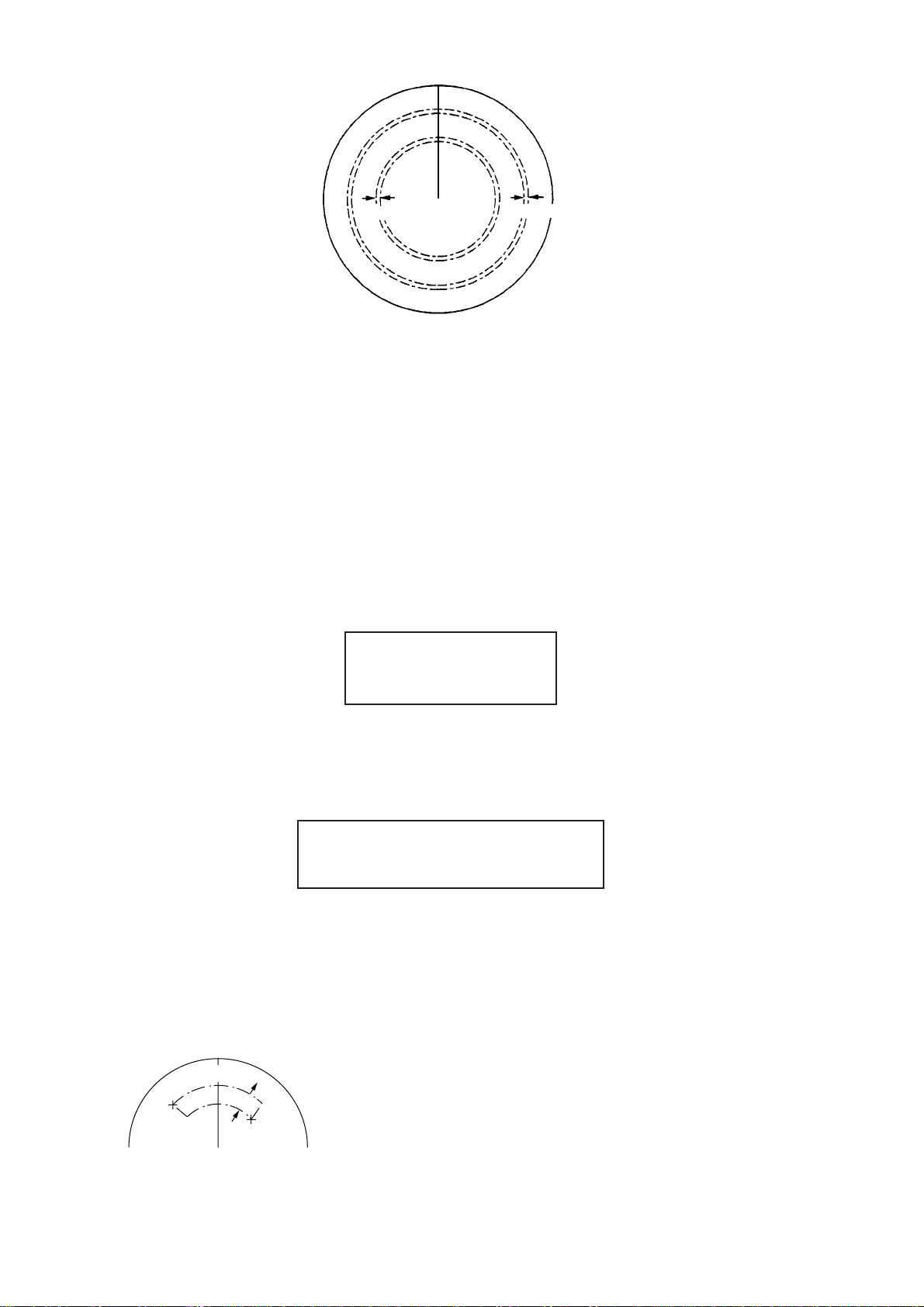
3.0-4.0 nm
5.0-6.0 nm
Figure 5-5 Predefined auto acquisition areas
Free selection of acquisition zones (Menu item: SET)
To set auto acquisition areas with trackball:
1. Press the [PLOT MENU] key to show the ARPA 1 menu.
2. Press the [3] key to select AUTO ACQ AREA.
3. Further press the [3] key to select (or highlight) SET.
4. Press the [ENTER] key to conclude your selection. At this point the AUTO ACQ SETTING menu is displayed.
[AUTO ACQ AREA SET]
1 [ARPA (1)]
2 1/2
Figure 5-6 AUTO ACQ AREA SET menu
5. Press the [2] key to select menu item “1/2” and press the [ENTER] key. Then, you will
see the message as shown below:
[AUTO ACQ SETTING]
1 [ARPA (1)]
2 1/2
Figure 5-7 AUTO ACQ SETTING menu
6. Place the cursor at the outer counterclockwise corner of the area (point A) and press
the [ENTER] key.
7. Place the cursor at the clockwise edge of the area (point B) and press the [ENTER]
key.
0.5-1.0nm
A
B
5-8
Page 91

Note: If you wish to create an auto acquisition area having a 360-degree coverage
around own ship, set point B in almost the same direction (approx. ±5°) as point A and
press the [ENTER] key.
8. Repeat steps 5 to 7 above if you want to set another auto acquisition area with the
trackball.
9. Press the [1] key followed by the [PLOT MENU] key to close the ARPA 1 menu.
An auto acquisition area like the example shown in Figure 5-5 appears on the display.
Note that each auto acquisition area has a fixed radial extension (width) of 0.5-1.0 nm.
Note that the auto acquisition areas are preserved in an internal memory of the ARPA
even when auto acquisition is disabled or the ARPA is turned off.
5.5.3 Terminating tracking of targets
When the ARP A has acquired 20 targets automatically , the message AUTO T ARGET FULL
is displayed at the screen center and no more auto acquisition occurs unless targets are
lost. You may find this message before you set an auto acquisition area. Should this happen, cancel tracking of less important targets or perform manual acquisition.
Canceling individual targets
Use the trackball to place the cursor (+) on a target to cancel tracking. Press the [T ARGET
CANCEL] key.
Canceling all targets at a time
Press and hold the [T ARGET CANCEL] key down more than 3 seconds. In the automatic
acquisition mode, acquisition begins again.
5.6 Manual Acquisition
In the auto acquisition mode (AUTO ACQ ON), up to 20 targets can be manually acquired
in addition to 10 auto acquired targets. When auto acquisition is disabled (AUTO ACQ
OFF), up to 30 targets can be manually acquired and automatically tracked.
To manually acquire a target:
1. Place the cursor (+) on a target of interest by operating the trackball.
2. Press the [ACQ] key on the control head. The selected plot symbol is marked at the
cursor position.
Note that the plot symbol is drawn by broken lines during the initial tracking stage. A vector
appears in about one minute after acquisition indicating the target’s motion trend. If the
target is consistently detected for three minutes, the plot symbol changes to a solid mark.
If acquisition fails, the target plot symbol blinks. It blinks until the [LOST T ARGET] is pressed
(to acknowledge it as a lost target).
5-9
Page 92

(a) Immediately after acquisition, this plot
symbol is shown in broken lines.
(b) Within 20 scans (or 1 min) of the antenna
after acquisition, a vector appears to show a
trend of movement.
(c) Within 60 scans (or 3 min) of the antenna
after acquisition, the plot symbol changes to
a small circle indicating steady-state
tracking condition.
Notes on manual acquisition
1) For successful acquisition, the target to be acquired should be within 0.2 to 32 nm from
own ship and not obscured by sea or rain clutter.
2) When you have acquired 30 targets manually, the message MAN TARGET FULL is
displayed at the screen bottom. Cancel tracking of non-threatening targets if you wish
to acquire additional targets manually. (See “5.5.3 Terminating tracking of acquired
targets” on page 5-9.)
CAUTION
TARGET SWAP
When a target being tracked nears
another target being tracked, the targets
may be “swapped”. When two targets
acquired either automatically or manually come close to each other, one of the
two may become a Lost Target. Should
this happen, manual re-acquisition of the
Lost Target may be required after the
two have separated.
Criteria of Tracking
A target measuring 800 m or more in the
radial or circumferential direction is
regarded as a landmass and not
acquired or tracked. Echoes smaller
than 800 m are regarded as targets to be
tracked.
5.7 Changing Plot Symbol Size, Plot Symbols
5.7.1 Changing plot symbol size
To choose a large or standard size for all plot symbols:
1. Press the [PLOT MENU] key followed by the [0] key to show the ARPA 2 menu.
2. Press the [6] key to select MARK SIZE.
3. Further press the [6] key to select (or highlight) ST ANDARD or LARGE as appropriate.
4. Press the [ENTER] key to conclude your selection followed by the [PLOT MENU] key
to close the ARPA 2 menu.
5-10
Page 93
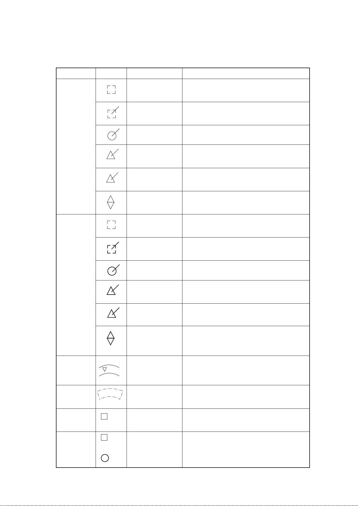
5.7.2 ARPA symbols
The symbols used in this equipment comply with IEC 60872-1.
metIlobmySsutatSskrameR
yllacitamotuA
egatslaitinI
deriuqca
stegrat
mralaAPC
(flashing)
mralaAPC
egdelwonkca
tegrattsoL
yllaunaM
egatslaitinI
deriuqca
stegrat
3.onlobmyssvpe
.gnikcart
3.onlobmyssvpe
gnikcartydaetS
a4.onlobmyssvpe
8.onlobmyssvpe
.degdelwonkca
8.onlobmyssvpe
9.onlobmyssvpe
3.onlobmyssvpe
.selgnairt
.noitisiuqcaretfa
3.onlobmyssvpe
ehtetacidniotohcenadnuoraerauqsnekorB
foegatslaitinidnanoitisiuqcarednutegrat
ehtetacidniotohcenadnuoraerauqsnekorB
foegatslaitinidnanoitisiuqcarednutegrat
.gnikcartetats-ydaetserofeb,gnikcart
etatsydaetsgnitacidnirotcevhtiwelcricdiloS
.)noitisiuqcaretfasnacs06(gnikcart
elgnairtlaretaliuqenaotsegnahclobmystolP
otdetciderpsitegratehtetacidniotgnihsalf
.APCTroAPCotniemoc
simralaAPCT/APCretfaspotsgnihsalF
dnomaidgnihsalfybdetacidnisitegrattsoL
lauqeowtmorfdemrofsidnomaidehT.lobmys
deriuqcategratarofdetceleslobmystolP
.senilnekorbdlobninwohssiyllaunam
annetnafosnacs06-02roferauqsnekorbdloB
)esruoc
(flashing)
tegrattsoL
(flashing)
enozdrauG
mrala
enozdraug
citamotuA
noitisiuqca
aera
tegraT
rofdetceles
1
tuodaeratad
ecnerefeR
tegrat
R1
In 60 scans,
changes to
gnikcartydaetS
a4.onlobmyssvpe
noisilloc(mralaAPC
.)noitisiuqcaretfasnacs
06(elcricdilosdlobanilobmystolplaunaM
elgnairtlaretaliuqenaotsegnahclobmystolP
ehtotniemocotdetciderpsitegratafignihsalf
8.onlobmyssvpe
.APCTroAPCteserp
simralaAPCT/APCretfaspotsgnihsalF
.degdelwonkca
8.onlobmyssvpe
dnomaidgnihsalfybdetacidnisitegrattsoL
lauqeowtmorfdemrofsidnomaidehT.lobmys
xeparehtoehtdnapuxepaeno(selgnairt
9.onlobmyssvpe
gnissaptegratnO
tes-rotarepourht
.)nwod
,elgnairtlaretaliuqenaotsegnahclobmystolP
tegratfirotcevhtiwrehtegotgnihsalf,nwodxepa
.enozdrauggniretne
7.onlobmyssvpe
0.4-0.3,mn0.6-0.5
.rotarepoehtybdetcelessaelcricllufforotceS
erehwynaromn
2.onlobmyssvpe
tegratdetcelesnO
8.onlobmyssvpe
)APCTdna
APC,deeps,esruoc,gniraeb,egnar(atadtegraT
tegratecnerefernOdnuorg-eht-revos'pihsnwoetaluclacotdesU
dnuorgrof)deepsdesab-tegrat(deeps
.noitazilibats
R1
5-11
Page 94

ARPA symbols (con’t.)
metIlobmySsutatSskrameR
lairT
revuenam
ecnamrofreP
tset
T
)gnihsalf(
XX
)gnihsalf(
retnecmottoB
01.onlobmyssvpe
retnecmottoB
a11.onlobmyssvpe
.revuenamlairtafonoitucexegnirudsraeppA
.tsetecnamrofrepafonoitucexegnirudsraeppA
5.7.3 ARPA, EPA symbols shown on fishing vessel specification
radar
metIlobmySsutatSskrameR
APE,APRA
slobmys
radarnoitacificeps
lessevgnihsifnielbaliavaslobmysAPE,APRA
5.8 Adjusting Brilliance of Plot Marks
1. Press [RADAR MENU], [0] to show the FUNCTIONS 2 menu.
2. Press the [9] and [0] keys to show the BRILLIANCE 2 menu.
3. Press the [2] key to select PLOT BRILL.
4. Further press the [2] key to select (or highlight) a desired brilliance level.
5. Press the [ENTER] key to confirm your selection followed by the [RADAR MENU] key
to close the BRILLIANCE 2 menu.
Note: Refer to paragraph 1.38 for the BRILLIANCE menu screen.
5-12
Page 95
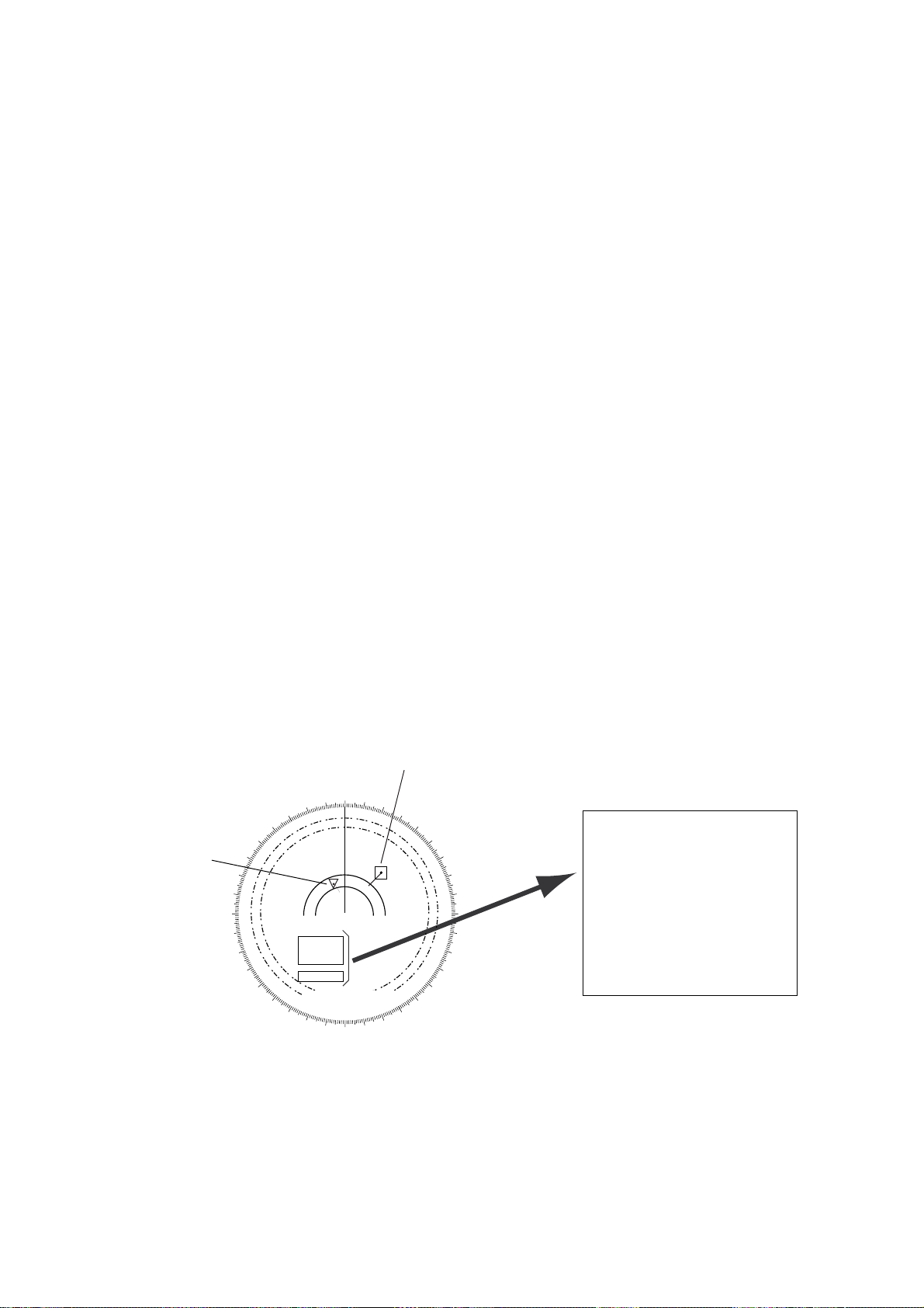
5.9 Displaying Target Data
The ARPA mode (with built-in ARP-26 optional board) provides the full functionality of
ARP A as required by the IMO Resolution A.823(19) and IEC 60872-1, including display of
range, bearing, course, speed, CPA and TCPA of all plotted targets. Data on one target
may be displayed.
In the head-up and head-up true bearing modes, target bearing, course and speed shown
at the center of the display become true (suffix “T”) or relative (suffix “R”) to own ship in
accordance with the true/relative vector setting. In north-up, course-up and true motion
modes, the target data field always displays true bearing, true course and speed over-theground or thru-the-water.
Place the cursor on a desired target and press the [TARGET DATA] key. Target data is
displayed as below.
RNG/BRG (Range/Bearing): Range and bearing from own ship to the selected target with
suffix “T” (True) or “R” (Relative).
CSE/SPD (Course/Speed): Course and speed are displayed for the selected target with
suffix “T” (True) or “R” (relative).
CPA/TCPA: CPA (Closest Point of Approach) is the closest range a target will approach to
own ship. TCPA is the time to CPA. Both CPA and TCPA are automatically calculated.
When the CP A has passed clear of own ship, it is indicated by a TCPA with a negative (-)
sign. TCP A is counted to 99.9 minutes and beyond this it is indicated as TCP A> -99.9MIN.
BCR (Bow Cross Range): Range at which target is to cross own ship’s bow.
BCT (Bow Cross Time): Time of BCR
Target accessed for data readout
000
010
Target in
GZ
270
280
260
290
250
300
240
310
230
340
330
320
Guard Zone
Acquisition Zone
220
210
200
350
190
180
170
020
160
01
030
150
140
040
130
050
120
060
070
110
080
100
090
01
RNG
BRG
CSE
SPD
CPA
TCPA
BCR
BCT>
0.439NM
122.7°T
254.2°T
14.9KT
0.4NM
0.0MIN
0.8NM
99.9MIN
Figure 5-8 ARPA plot
5-13
Page 96
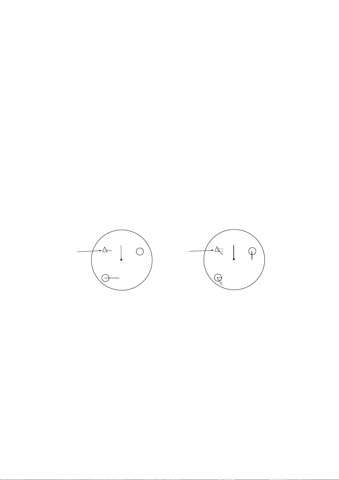
5.10 Vector Modes
Target vectors can be displayed relative to own ship’s heading (Relative) or north (True).
5.10.1 Ground stabilization and sea stabilization
Target vectors can be ground stabilized or sea stabilized. Sea stabilization is a mode
where own ship and all targets are referenced to the sea using gyro heading and single
axis log water speed inputs in the True Motion mode. Ground stabilization is a mode
where own ship and all targets are referenced to the ground using the ground track or set
and drift inputs. If the accuracy seems unsatisfactory, enter the set and drift correction
(paragraph 5.12).
5.10.2 True vector
Vector mode, True or Relative, is selected with the [VECTOR] key. True vectors are the
predicted true motion of a target as a result of own ship’s direction and speed input. With
true vectors the radar display will look like the one in (a) in the figure below.
In the true motion mode, all fixed targets, such as land, navigational marks and ships at
anchor , remain stationary on the radar screen with vector length zero. But in the presence
of wind and/or current, vectors appear on fixed targets representing the reciprocal of set
and drift affecting own ship unless set and drift values are properly entered.
Target on
collision course
(a) True vectors in head-up mode (b) Relative vectors in head-up mode
A
(flashing)
B
Own ship
Buoy
(flashing)
A
Target on
collision course
B
Buoy
Own ship
Figure 5-9 True and relative vectors in the head-up mode
5.10.3 Relative vector
True vectors are the predicted movement of a target relative to own ship. With relative
vectors the radar display will look like (b) in the figure above.
Relative vectors on targets which are not moving over the ground, such as land, navigational marks and ships at anchor, will represent the reciprocal of own ship’ s ground track.
A target of which vector extension passes through own ship is on the collision course.
(Dashed lines in the figure are for explanation only.)
5-14
Page 97

5.10.4 Vector time
Vector time (or the length of vectors) can be set to 30 seconds, 1, 2, 3, 6, 12, 15 or 30
minutes and the selected vector time is indicated at the screen center.
1. Press the [PLOT MENU] key to display the ARPA 1 menu.
2. Press the [1] key to select VECTOR TIME.
3. Further press the [1] key to select (or highlight) a desired vector time.
4. Press the [ENTER] key to conclude your selection.
5. Press the [PLOT MENU] key to close the menu.
The vector tip shows an estimated position of the target after the selected vector time
elapses. It can be valuable to extend the vector length to evaluate the risk of collision with
any target.
5.11 Past Position Display
The ARPA displays equally time-spaced dots marking the past positions of any targets
being tracked.
A new dot is added every minute (or at preset time intervals) until the preset number is
reached. If a target changes its speed, the spacing will be uneven. If it changes course, its
plotted course will not be a straight line.
5.1 1.1 Displaying and erasing past positions
To display past positions;
1. Press [PLOT MENU], [0] to display the ARPA 2 menu.
[ARPA (2)]
1 [ARPA (1)]
2 TRIAL MODE STATIC/DYNAMIC
3 HISTORY OFF/ON
4 HISTORY POINTS 5/10/20
5 HISTORY INTERVAL 30SEC/1/2/3/6MIN
6 MARK SIZE STD/LARGE
7 GUARD, ACQ STABILIZE NORTH/CRT
8 [INPUT SIG CHECK (1)]
9 [ARPA TRACK TEST]
0
Figure 5-10 ARPA 2 menu
2. Press the [3] key twice to select HISTORY ON.
3. Press the [ENTER] key followed by the [PLOT MENU] key. The label HISTORY appears on the display.
To erase past positions, press the [3] key at step 2 in the above to procedure to display
HISTORY OFF.
5-15
Page 98

5.11.2 Selecting the number of dots and past position plot
intervals
1. Press [PLOT MENU], [0] to show the ARPA 2 menu.
2. Press the [4] key to select HISTORY POINTS.
3. Further press the [4] key to select a desired number of past positions (5, 10 or 20).
4. Press the [ENTER] key to confirm your selection.
5. Press the [5] key to select HISTORY INTERVAL.
6. Further press the [5] key to select a desired past position plot interval (0.5, 1, 2, 3 or 6
minutes).
7. Press the [ENTER] key to conclude your selection.
8. Press the [PLOT MENU] key to close the menu.
5.12 Set and Drift (Set and Rate)
Set, the direction in which a water current flows, can be manually entered in 0.1-degree
steps. Drift, in another word Rate, the speed of tide, can also be entered manually, in 0.1
knot steps. Set and drift corrections are beneficial for increasing the accuracy of vectors
and target data. The correction is best made in the head-up mode with true vectors, watching
landmasses, or other stationary targets. Thus, the speed and course of own ship over the
ground are reciprocally calculated and compared with the relative bearing and range to
the reference target to produce a Set and Drift. These values are automatically applied to
all targets. If stationary targets have vectors, set and drift values should be adjusted until
they lose their vectors.
To enter set and drift (rate):
1. Press the [RADAR MENU] key to show the FUNCTIONS 1 menu.
2. Press the [0] key to show the FUNCTIONS 2 menu.
3. Press the [7] key to select SET, DRIFT.
4. Further press the [7] key to select OFF or MAN.
OFF: No correction against set and drift.
MAN: Manual entry of set and drift data.
5. If OFF is selected at step 4 above, press the [ENTER] key.
6. If you selected MAN in step 4 above, the highlight cursor will advance to the right
requesting you to enter SET 000.0°. Enter the value of set in degrees by hitting numeric keys without omitting leading zeroes, if any, and press the [ENTER] key.
The highlight cursor will then advance to the next line DRIFT 00.0KT. Enter the value of
drift in knots by hitting numeric keys without omitting leading zeroes, if any, and press
the ENTER key. Set and drift have the same effect on own ship and all targets.
5-16
Page 99

7. Press the [RADAR MENU] key to close the menu. The label LOG (or NA V) changes to
WT (Water Tracking) or BT (Bottom Tracking). Set and drift data can also be used in
the basic radar without ARPA function.
5.13 Setting CPA/TCP A Alarm Ranges
The ARPA continuously monitors the predicted range at the Closest Point of Approach
(CPA) and predicted time to CPA (TCPA) of each tracked target to own ship.
When the predicted CP A of any target becomes smaller than the preset CPA alarm range
and its predicted TCPA less than a preset TCPA alarm limit, the ARPA releases an aural
alarm and displays the warning label COLLISION on the screen. In addition, the ARPA
symbol changes to a triangle and flashes together with its vector.
Provided that this feature is used correctly, it will help avoid collision by alerting you to
threatening targets. It is important that GAIN, A/C SEA, A/C RAIN and other radar controls
are properly adjusted.
CPA/TCPA alarm ranges must be set up properly taking into consideration the size, tonnage, speed, turning performance and other characteristics of own ship.
CAUTION
The CPA/TCPA alarm feature should
never be relied upon as the sole means
for detecting the risk of collision. The
navigator is not relieved of the responsibility to keep visual lookout for avoiding
collisions, whether or not the radar or
other plotting aid is in use.
5.13.1 Setting CPA/TCPA alarm ranges
To set the CPA/TCPA alarm ranges:
1. Press the [PLOT MENU] key to show the ARPA 1 menu.
2. Press the [8] key to select menu item COLLISION ALARM. At this point, a highlight
cursor appears at the “CPA 0.0 NM” field.
3. Enter the CPA alarm range in nautical miles (0.0 to 9.9 nm) without omitting leading
zeroes, if any, and press the [ENTER] key. The highlight cursor now moves to the
“TCPA 00x.0 MIN” field.
4. Enter the TCP A alarm limit in minutes (1.0 to 99.9 min) without omitting leading zeroes,
if any, and press the [ENTER] key.
5. Press the [PLOT MENU] key to close the menu.
5-17
Page 100

5.13.2 Acknowledging CPA/TCPA audible alarm
Press the [AUDIO OFF] key to acknowledge and silence the CPA/TCPA aural alarm.
The warning label COLLISION and the flashing of the triangle plot symbol and vector
remain on the screen until the dangerous situation is gone or you intentionally terminate
tracking of the target by using the [TARGET CANCEL] key.
5.14 Setting a Guard Zone
When a target transits the operator-set guard zone, the buzzer sounds and the indication
GUARD turns red at the screen bottom. The target causing the warning is clearly indicated
with an inverted flashing triangle.
CAUTION
Guard Zone Alarm
The guard zone alarm should not be relied upon as the sole means for detecting
possible collision situations. The operator of a ship is not relieved of the responsibility to keep lookout for possible
collisions, whether or not the radar is
in use.
5.14.1 Activating the guard zone
One or two guard zones may be selected. The No. 1 guard zone is available between 3
and 6 nm and the No. 2 guard zone can be set anywhere when the No. 1 zone is already
in use.
To set and activate the guard zone:
1. Press the [PLOT MENU] key to show the ARPA 1 menu.
2. Press the [4] key to select GUARD ZONE.
3. Further press the [4] key to select (or highlight) ON to activate the guard zone.
4. Press the [ENTER] key to conclude your selection.
5. Press the [5] key to select GUARD ZONE SET. At this point the GUARD ZONE SET
menu appears.
5-18
 Loading...