

Page 1
Page 2
9-52 Ashihara-cho,9-52 Ashihara-cho,
A
A
*00080756800**00080756800*
*00080756800**00080756800*
*OME72410M00**OME72410M00*
Nishinomiya, JapanNishinomiya, Japan
Telephone :Telephone : 0798-65-21110798-65-2111
Telefax :Telefax : 0798-65-42000798-65-4200
ll rights reserved.
ll rights reserved.
PUB.No.PUB.No. OME-72410OME-72410
Printed in JapanPrinted in Japan
Your Local Agent/DealerYour Local Agent/Dealer
IRST EDITION :
IRST EDITION : APR.APR. 19961996
MM :: FEB.FEB. 12,200312,2003
(( DAMIDAMI ))
DS-50DS-50
* 0 0 0 8 0 7 5 6 8 0 0 ** 0 0 0 8 0 7 5 6 8 0 0 *
*OME72410M00**OME72410M00*
* O M E 7 2 4 1 0 M 0 ** O M E 7 2 4 1 0 M 0 *
Page 3
SAFETY INSTRUCTIONS
WARNING
ELECTRICAL SHOCK HAZARD
Do not open the equipment.
Only qualified personnel
should work inside the
equipment.
Immediately turn off the power at the
switchboard if water leaks into the
equipment or an object is dropped into
the equipment.
Continued use of the equipment can cause
fire or electrical shock. Contact a FURUNO
agent for service.
Do not place liquid-filled containers on
the top of the equipment.
Fire or electrical shock can result if the
liquid spills into the equipment.
Do not disassemble or modify the
equipment.
CAUTION
Do not use the equipment for other than
its intended purpose.
Improper use of the equipment can result
in personal injury or equipment damage.
Turn off the equipment immediately if
you feel it is abnormal.
Turn off the power from the switchboard if
the equipment is emitting strange noises
or becomes excessively hot. Contact your
dealer for advice.
The useable ambient temperature range
is 15°C
Do not use the equipment out of the
above temperature range.
Do not place objects around the
equipment.
Overheating may result.
to
55°C.
Fire, electrical shock or serious injury can
result.
Keep the equipment away from rain
and water splash.
Fire or electrical shock can result if the
rain or water gets into the equipment.
Do not operate the equipment with wet
hands.
Electrical shock can result.
Keep heater away from equipment.
A heater can melt the equipment's power
cord, which can cause fire or electrical
shock.
Use the proper fuse.
Fuse rating is shown on the equipment.
Use of a wrong fuse can result in damage
to the equipment.
Do not power the equipment when the
transducer is in air.
The transducer may become damaged.
Handle all units carefully.
Damage can lead to corrosion.
Do not use chemical cleaners such as
alcohol, acetone and benzine to clean
the equipment.
Chemical cleaners can remove paint and
markings. Use only a soft, dry cloth. For
stubborn dirt, use a soft cloth moistened
with water-diluted mild detergent.
When dry docked remove marine life
from the transducer.
Remove marine life to maintain good
sensitivity.
Do not paint the transducer face.
Further, handle the transducer with
care.
Paint will affect equipment performance.
i
iiiiiiiiiiiii
Page 4
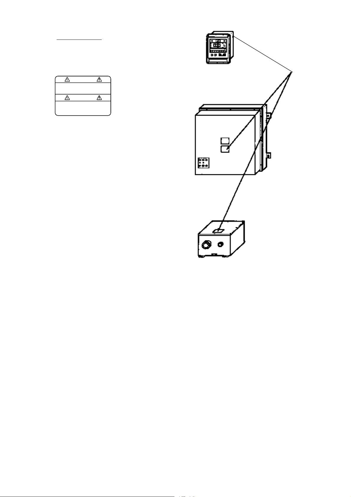
WARNING LABEL
A warning label is attached to the
units shown right. Do not remove the
labels. If a label is missing or is illegible,
contacta FURUNO dealer or agent about
replacement.
WARNING
To avoid electrical shock, do not
remove cover. No user-serviceable
parts inside.
Name: Warning Label (1)
Type: 86-003-1011
Code No.: 100-236-230
MAIN DISPLAY UNIT
DS-500
PROCESSOR UNIT
DS-510, DS-511
Warning
label
TRANSCEIVER UNIT
DS-520
ii
iiiiiiiiiiiiiiiiiiiiiiiiii
Page 5

TABLE OF CONTENTS
INTRODUCTION................................................................................................................1
SPECIFICATIONS .............................................................................................................2
SYSTEM CONFIGURATION .........................................................................................5
OPERATION ........................................................................................................................6
Controls and Indications on the Main Display Unit ........................................................... 6
Turning on the Power, Adjusting Panel Brilliance..............................................................8
Selecting Speed Tracking Mode .........................................................................................9
Selecting Unit of Speed Measurement................................................................................9
Displaying Distance Run or Keel Clearance ......................................................................9
Setting Distance Run ........................................................................................................10
System Settings.................................................................................................................11
CONTROL BOX (option) OPERATION ..................................................................13
MAINTENANCE & TROUBLESHOOTING ............................................................14
Preventive Maintenance....................................................................................................14
Troubleshooting ................................................................................................................15
Operation Checks..............................................................................................................15
Error Displays.........................................................................................................................17
Program Number ..............................................................................................................17
PRINCIPLE OF DOPPLER SPEED LOG...............................................................18
DIGITAL INTERFACE (IEC 61162-1 EDITION 2) ..................................... 19
Declaration of Conformity
iii
Page 6

SPECIFICATIONS
General Specifications
1. Ultrasonic frequency 440 kHz
2. Number of beams 3 beams for dual-axis speed indication
3. Measuring range and accuracy
Ship's speed Fore/aft: -10.0 to +40.0 kt
Port-Starboard: -9.9 to +9.9 kt
Working depth Ground tracking: 1 to 200 m beneath the keel
Water tracking: 3 to 25 m below hull bottom. (It will
change by installation conditions and surrounding water
conditions of transducer. The measuring accuracy will be
reduced for the depth shallower than 30 m.)
Total distance run 0 to 99999.99 nm
Accuracy (ship's speed) 1.0% or 0.1 kt, whichever is greater. Rolling ±10°, pitching
±5°
4. Display
Main display unit LED
Digital indicator LCD or LED
5. Input/Output signals
Input External keying pulse: 2 ports
Output Ship's speed: 2 ports (digital) 1 port (analog or through
distribution box)
Distance signal: 1 port (400 p/nm, forward data only)
Distance signal: 6 ports with contact closure signal,
200 p/ nm, contact capacity 30 V,
max 0.2A, forward data only.
Alarm signal: 1 port (contact closure signal, contact
capacity 30 V, max 0.2 A)
Keying pulse: 1 port
Digital interface IEC 61162-1 2nd Edition: 2 ports
VBW, VTG, VHW, VLW (VTG is not output when the
seabed is not acquired. Heading data in VTG and VHW is
"null".)
6. Power supply 100/110/115/220 230 VAC, 50/60 Hz
7. Environmental conditions Standards: IEC 945 test methods
In-bridge units -15°C to +55°C
Relative humidity 95% at 40°C
Note: Performance may be affected by air bubbles, interference and other factors.
2
Page 7

Specifications of DS-350/351 Digital Display (option)
1. Display device DS-350: LCD, DS-351: LED
2. Indication
Speed Fore/Aft: ❐❐.❐❐
Port/Starboard: ❐.❐❐
Unit Knots or meters/second
Direction cd (Fore/Aft), [ \ (Port/Starboard)
Mode Ground or Water tracking
Depth (clearance) ❐❐ .❐ m
3. Other features Dimmer controls, Mode selector, Unit of speed selector
4. Power consumption DS-350: 12 VA, DS-351: 44 VA
Specifications of DS-370 Distribution Box (option)
1. Input signal (TTL level) Digital speed signal
Log signal (400 p/nm)
Alarm signal
Power on/off signal
2. Output signal The following output boards are available optionally.
(1) OTX board Serial signal for DS-350/351 Digital Indicator and/or
cascade connection of DS-370 Distribution Box (1 port /1
board)
(2) ODD board BCD serial signal for DS-720/DS-370/DS-377 Digital
Display (Analog current signal for analog display, 1 board),
-2.5 mA to 10.0 mA/-10 kt to 40 kt or -3.33 mA to 10.0
mA/ - 10 kt to 30 kt
(3) OAD board Analog current signal for analog display, 1 board, -2.5 mA
to 10.0 mA/-10 kt to 40 kt or -3.33 mA to 10.0 mA/-10 kt
to 30 kt
(4) OLG board For Distance Indicator (1 port /1 board) and Log signal
(3 ports /1 board, 200/400 p/nm contact closure signal, 30
V/0.2A or RS-422 current loop signal). One Log signal
port can be modified for Fore/aft status signal port (contact
closure signal, 30 V/0.2A or RS-422 current loop signal).
(5) OAC board Ship's speed current voltage signal (1 port /1 board), Cur-
rent signal (4.0 mA to 20.0 mAI-10 kt to max, speed, max
impedance: 250 ohms)
3
Page 8

(6) OAV board Ship's speed voltage signal (1 port / 1 board), voltage
signal (-2.50 to 10.0 V/-10 kt to 40 kt, -3.33 V to 10.0 V/
-10 kt to 30 kt, -4.00 V to 10.0 V/-10 kt to 25 kt, -5.00 V to
10.0 V/-10 kt to 20 kt, max, impedance: l kohm) + Fore aft
status signal (RS-422 current loop)
3. Power supply and power 115/230 VAC, 1ø, 50/60 Hz, 50 VA max
consumption
Specifications of DS-381 Series Analog Display (option)
1. Indication system Dual range system
2. Panel dimensions ø200 mm
3. Power consumption 5 VA approx.
Specifications of DS-382 Series Analog Display (option)
1. Indication system Dual range system
2. Panel dimensions ø200 mm
3. Power consumption 5 VA approx.
Specifications of DS-501 Control Box (option)
1. Installation method Flush mount
2. Power consumption 200 mW max
3. Illumination LED
Specifications of DS-730 Distance Indicator (option)
1. Distance run indication ❐❐❐❐❐.❐ nm
2. Indication system LCD with dimmer
3. Power consumption 2.5 VA approx.
Specifications of DS-760 Series Analog Display (option)
1. Indication range -10 to 30 kt
2. Panel dimensions DS-761/762: ø200 mm
DS-763: ø100 mm
3. Power consumption 5 VA approx.
4
Page 9
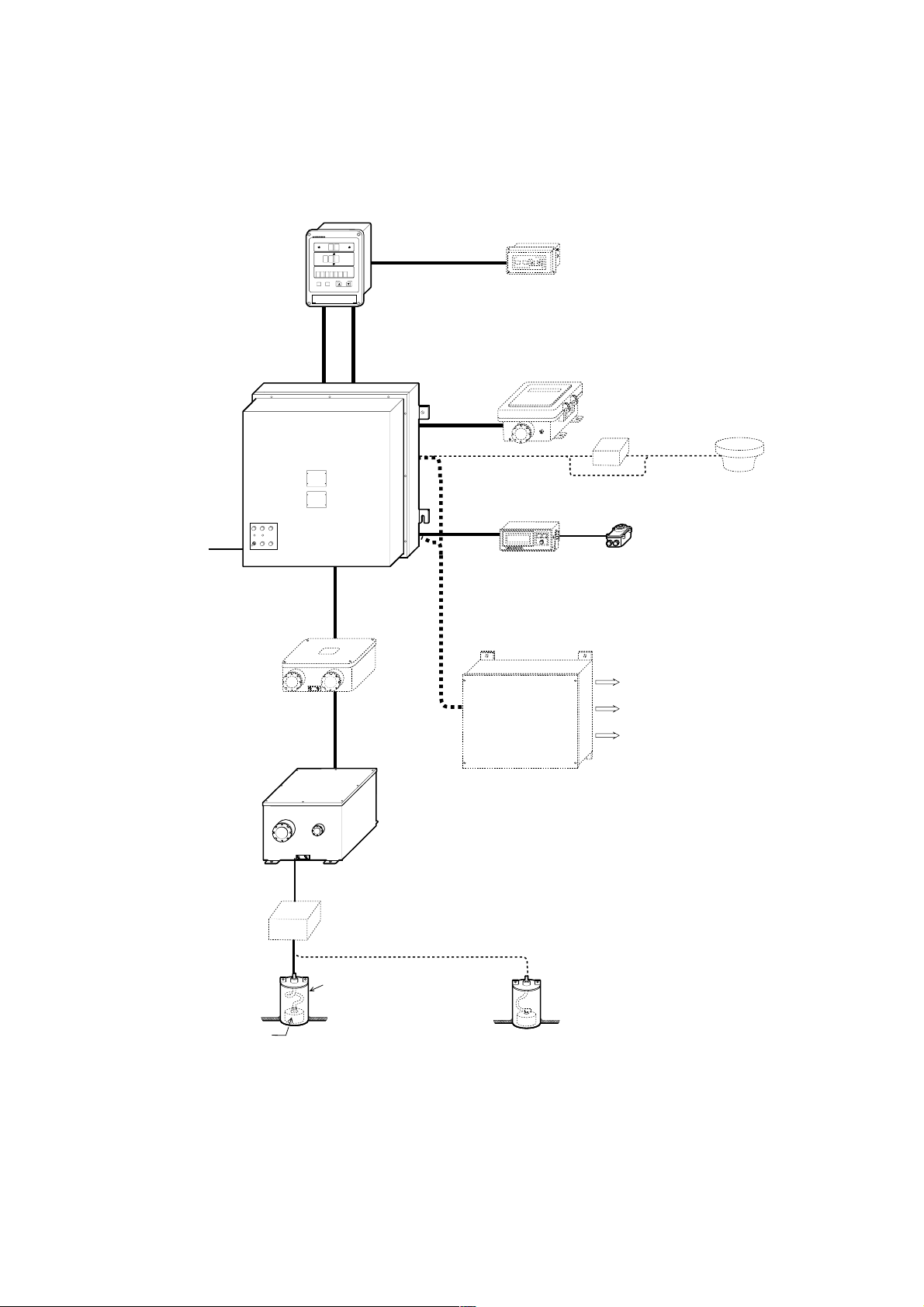
PROCESSOR
UNIT DS-511/510
SHIP'S MAINS
115/230 VAC,
50/60 Hz, 1¿
SYSTEM CONFIGURATION
MAIN DISPLAY UNIT
SIGNAL
cable
DS-50
G
G
W
W
A
A
T
T
kt
kt
m/s
m/s
AL
AL
f t
f t
f a
f a
nm
nm
POWER cable
CONTROL BOX
DS-501 (option)
DIGITAL DISPLAY
DS-350/351 (option)
DISTANCE
INDICATOR
DS-730 (option)
RANGE
SWITCH BOX
DS-389, HF-22A
DIMMER MF-22L
ANALOG INDICATOR
DS-381/382
MF-22A
JUNCTION BOX
DS-360 (option)
TRANSCEIVER UNIT
DS-520
TRANSDUCER
DS-530
DISTRIBUTION BOX
DS-370 (option)
DISTANCE RUN INDICATOR
DIGITAL DISPLAY
ANALOG DISPLAY
Note: When Processor Unit DS-510
is used Transceiver Unit is
incorporated in the DS-510.
JUNCTION BOX
CI-630
(option)
TRANSDUCER TANK
DS-531 or
GATE VALVE DS-532
TRANSDUCER TANK DS-331 /
TRANSDUCER DS-330
or
GATE VALVE for TRANSDUCER DS-335
5
Page 10

OPERATION
Controls and Indications on the Main Display Unit
Port or starboard speed
Port and starboard
direction indicators
Fore or aft
speed
Tracking mode
indicator
Ground
Water
Automatic
MODE selector
Selects tracking
mode.
Distance/Keel
Clearance selector
Displays distance run
or keel clearance.
speed measurement.
FURUNOFURUNO
G
W
A
D
istance
MODE
Kt/ m/s selector
Selects unit of
DOPPLER SONAR
DS-50
T
kt
m/s
AL
DIMMER
▲
ft
fa
nm
▲
Keel Clearance
Distance
Keel
Clearance
▲
▲
SET and arrow keys
Set distance run.
Fore and aft
direction indicators
Test mode indicator
Unit of speed (knot or
meters/second)
Speed alarm
Unit of keel clearance
or distance run:
ft (feet), fa (fathoms), or
nm (nautical miles)
DIMMER controls
Adjust brilliance.
Push here to
open lid.
POWER
switch
Note: Performance may be affected by air bubbles, interference and other factors.
6
Page 11

Control description
Main controls
MODE selector Selects tracking mode among ground, water and automatic. Each time the
key is pressed the tracking mode changes in the sequence of ground, water
and automatic. Current tracking mode is denoted by the tracking mode
lamps.
Distance/Keel Displays distance run or depth below keel at each pressing.
Clearance selector "Distance" or "Keel Clearance" lights to show current selection.
DIMMER controls Adjust panel brilliance.
Controls in compartment
Kt / m/s
SET
ts
Distance Set
▲
▼
POWER
Kt/ m/s selector Selects the unit of speed measurement; knots or meters/second.
SET key Sets distance run display.
Arrow keys Set the distance run indication.
POWER switch Turns power on and of f.
7
Page 12

Turning on the Power, Adjusting Panel Brilliance
1. Press the [POWER] switch to turn on the power. The equipment is tested in the sequence
below:
1) Communications test between main display unit and the processor unit is conducted.
Three zeroes blink about 30 s.
MODE
G
W
A
DOPPLER SONAR
Distance
Keel
Clearance
Keel Clearance
DS-50
DIMMER
T
kt
m/s
AL
Zeroes blink for
about 30 s.
ft
fa
nm
FURUNOFURUNO
Distance
Power switch behind
the cover
2) Testing of main display and processor unit begins. Memory, LEDs and buzzer are tested
in order, each tested eight times consecutively. Then the program version number of
both the main display unit and the processor unit appear.
G
T
kt
W
A
m/s
AL
Program Version NO.
of main display unit
Distance
Keel Clearance
ft
fa
Program Version NO.
nm
of processor unit
The equipment is normal if the program version nos. appear. If an error is found an error
message appears instead of a program version number. Error messages are described on
page 16.
3) The normal display appears, showing speed and distance run (or depth below keel).
2. Adjust panel brilliance with the [DIMMER] controls. Eight levels of brilliance are available. Selected brilliance appears below the distance run and depth display for 0.5 seconds.
8
Page 13

Selecting Speed Tracking Mode
Press the [MODE] selector to select speed tracking mode among water, ground or automatic.
Select the mode considering depth and speed. "G", "W" or "A" lights to show mode selected.
G: Measures and displays a speed relative to ground. The depth range usable for this mode is 1
to 200 meters below the keel.
W:Measures and displays a speed relative to the watermass. The depth from the keel to the
seabed should be three meters or more.
Note: It is recommended to use the water tracking mode in operation with an ARPA for
collision avoidance task.
A: Automatically selects ground tracking mode or water tracking speed mode depending on
depth. Water tracking mode is selected when the keel clearance exceeds 200 meters.
Note: Actual working depth in the ground tracking mode depends on seabed and water condi-
tions, and the reflecting properties for sonic pulses.
Selecting Unit of Speed Measurement
Speed can be measured in knots or meters/second. Press the [Kt/ m/s] selector to select the unit.
"Kt" or "m/s" lights to show the selection.
Displaying Distance Run or Keel Clearance
Press the [Distance/Keel Clearance] selector to display distance run or keel clearance (depth).
Distance run is always displayed in nautical miles. Keel clearance is the depth from the transducer to the seabed, and can be displayed in meters, feet or fathoms. See page 11 for how to
select unit of keel clearance measurement.
9
Page 14

Setting Distance Run
The distance run indication is backed up with an internal battery when the power is off. To reset
or change the distance run, do the following:
1. Open the lid at the bottom of the display unit and press the [SET] key. The display should
look like the illustration below, with the highest digit of distance run blinking.
0 0
1 2 3 0 0
1 2 3 0 0
Blinking
nm: Before pressing [SET] key
nm: After pressing [SET] key
2. Press t or s to place the blinking cursor on the digit to change.
3. Press ▲ or ▼ to set.
4. Repeat steps 2 and 3 to change other digits.
Note 1: Distance run can be reset to zero by entering all zeroes.
Note 2: T o restore previous distance run setting, do not operate arrow keys or [SET] key for
more than 10 seconds. When this is done the distance run indication stops blinking and then
the previous setting is restored. Note that if the ship is moving at this time the distance run
indication will change.
5. Press the [SET] key.
10
Page 15

System Settings
The system settings do not require frequent adjustment. The table below shows setting range
and default setting for each parameter.
.oNmetIegnaRgnitteSgnitteStluafeD
1tesffodeepsdnuorGspets%1.0,%7.21+ot8.21-%0
2tesffodeepsretaWspets%1.0,%7.21+ot8.21-%0
3tesffonoitallatsnirecudsnarT7.21+ot8.21-°1.0,°spets0°
4tesffoelgnamirT7.21+ot8.21-°1.0,°spets0.0°
5tesffoelgnaleeH7.21+ot8.21-°1.0,°spets0.0°
6gnigarevadeepSces09,06,03,51ces51
7htpeddeepsretawecnerefeRspetsm1,m0.52ot0.2m2
8ecnatsid1PKlanretxEspetsm1.0,m0.003+ot0.00.0
9ecnatsid2PKlanretxEspetsm1.0,m0.003+ot0.00.0
01tnemerusaemecnaraelcleekfotinUaf/tf/mm
Note: The above settings are retained with an internal battery when the power is off.
11
Page 16

Setting procedure
1. Turn off the main display unit. Turn on the power while pressing and holding down the
[Distance/Keel Clearance] selector. "1" indicates system setting no. 1 at the center of the
display.
FURUNOFURUNO
D
MODE
G
W
A
istance
DOPPLER SONAR
Distance
Keel
Clearance
Keel Clearance
DS-50
DIMMER
T
kt
m/s
AL
"1" appears.
ft
fa
nm
Setting
(The number corresponds to that on
the table on page 11.)
Hinged cover
2. Press ▲ or ▼ to select system setting number to be changed.
3. Press t or s to change setting.
4. Press ▲ or ▼ to verify the data entered.
5. Turn off the power, and the new settings are entered in memory.
12
Page 17

CONTROL BOX (option) OPERATION
The DS-501 Control Box provides remote operation of the main display unit. The [MODE],
[Distance/ Keel Clearance] and [DIMMER] controls function the same as those found on the
main display unit.
DS-50
DS-50
DIMMER
DIMMER
MODE
Distance
Keel
Clearance
REMOTE CONTROL
REMOTE CONTROL
13
Page 18

MAINTENANCE & TROUBLESHOOTING
WARNING
Do not open the equipment.
High voltage which can shock,
burn or cause serious injury
exists inside the equipment.
Do not work inside the equipment unless familiar with
electrical circuits.
Preventive Maintenance
Monthly checks
Check the following monthly:
• All connectors and cables are securely connected.
• Check ground of main display unit and processor unit for rust. Clean if necessary.
• Check that power voltage is within prescribed rating.
• Conduct the diagnostic program.
Cleaning
Display unit
Dust and dirt may be wiped off the main display unit with a soft cloth. Mild detergent may be
used if necessary. Do not use chemical cleaners to clean the unit—they may remove paint and
markings.
Transducer
Marine life (barnacles, etc.) on the transducer can cause a considerable drop in sensitivity.
When the ship is docked, carefully remove any marine life from the transducer . Paint the transducer yearly with Marine Star 20C (no other paint allowed) anticorrosion paint.
14
Page 19

Troubleshooting
Below are simple troubleshooting procedures the operator can follow to restore normal operation.
Power cannot be turned on.
• Try adjusting brilliance (power may be on but brilliance is too low).
• Check the power cable for damage.
• Check that the power connector is firmly fastened.
• Check if fuse(s) on the processor unit have blown. If a fuse has blown, find out the cause
before replacing it. Be sure to use proper fuse. Fuse rating appears below fuse holder.
Poor accuracy.
• Check if ground has corroded or ground connection has loosened.
• Check if cables of other equipment are near the transducer cable.
Operation Checks
Main display unit
1. Turn on the power while pressing and holding down the [MODE] selector. The following
appears when the equipment is normal:
Port/starboard speed: 0.5 kt \
Fore/aft speed: c 18.9 kt
Distance run: 12345.67
Depth: 12.3 (unit according to system settings)
2. Operate the [MODE], [Distance/Keel Clearance] and [Kt / m/s] controls one by one. Confirm that mode or indications changes with each pressing.
3. Confirm that distance run setting can be changed.
Interconnection between main display unit and remote indicators
1. Turn on the power while pressing and holding down the [SET] key . 10.0 kt for fore/aft speed
appears. "T" appears to denote the test mode.
2. Confirm that the remote indicators display 10.0 kt. If not, there may be some problem between the processor unit and remote indicators.
15
Page 20

Main display unit diagnostic program
The diagnostic program checks the main display unit for proper operation and is automatically
conducted at start up. It may also be conducted when necessary . The program checks the memory
(ROM, RAM, EEPROM), LEDs and buzzer and then shows the program version number . The
equipment is normal if the program version no. appears.
1. To run the diagnostic program, turn on the power while pressing the [Kt / m/s] selector . The
program checks the LEDs, ROM, RAM, EEPROM and buzzer and displays the program
version number. This is done continuously.
2. To escape from the diagnostic program, turn off the power.
Error display
FURUNOFURUNO
D
MODE
G
W
A
istance
DOPPLER SONAR
Distance
Keel
Clearance
Keel Clearance
DS-50
DIMMER
T
kt
m/s
AL
Main display unit
error indications
1: ROM error
2: RAM error
3: EEPROM error
ft
fa
nm
16
Page 21

Error Displays
Processor unit
error indications
1: MCP Board
error
Program Number
FURUNOFURUNO
DOPPLER SONAR
G
W
A
Distance
Distance
Keel
MODE
Clearance
2: MFT Board
error
Keel Clearance
DS-50
T
kt
m/s
AL
ft
fa
nm
DIMMER
3: MCP Board
error
Main display unit
error indications
1: ROM error
2: RAM error
3: EEPROM error
4: MIF Board
error
,.oNbuP
.oNmargorPerawfoS
,noitacifidoM
etaD
K-01427-EMO
xifotdeifidoM
005-SD
300-0040-566draobPC
ecnetnesGTV
015-SD
2002/7
700-0140-566draobPC
000-0210-566draobTF
100-2210-566draobFI
17
Page 22

PRINCIPLE OF DOPPLER SPEED LOG
A doppler speed log measures ship's speed by utilizing the principle of the Doppler effect, which defines
that a signal emitted from a moving object is heard
with its frequency shifted at stationary locations and
the degree of the frequency shift is proportional to the
speed of the moving object.
For ease of understanding measurement of ship's
fore-aft speed is explained in this paragraph.
Although the DS-50 employs three directional beams,
let's suppose that only two beams are used as shown
at right.
Ultrasonic pulses are emitted at an angle of θ relative
to water line toward ship's fore and aft direction. If
the ship's speed is "V", the source of the ultrasonic
pulse approaches or goes away the reflecting points
on the seabed at a speed of Vcosθ.
This relative motion causes the Doppler shift and the
ultrasonic signals reflected at the seabed are received
at frequencies of "fo + fd" and "fo - fd" by the transducer. In the processor unit of the DS-50, difference
of "fo + fd" and "fo - fd" are computed to extract only
the Doppler shift factor "fd".
(fo+fd) -(fo-fd) = 2fd
Since the 'fd' is theoretically given by
θ
fd = 2Vcos
and fo, C and
Note that the sound velocity in water changes with water temperature and water pressure but
the change by water temperature is automatically compensated for by using temperature sensor .
x fo/C (C: Sound velocity in water)
θ
are known, V can be calculated if the "fd" is given.
18
Page 23

DIGITAL INTERFACE IEC 61162-1
EDITION 2
Output sentences of channel 1, 2 (NMEA/CIF 1, NMEA/CIF 2)
VBW, VTG, VLW, VHW. (VTG is not output when the bottom echo has not been acquired.
Heading data in VTG and VHW is "null.")
Transmission interval
1 s for any sentence
Data transmission
Data is transmitted in serial asynchronous form in accordance with the standard referenced in
2.1 of IEC 61162-1. The first bit is a start bit and is followed by data bits, least-significant-bit as
illustrated below.
The following parameters are used:
Baud rate: 4800
Data bits: 8 (D7 = 0), parity none
Stop bits: 1
D0 D1 D2 D3 D4 D5 D6 D7
Start
bit
Data bits
Stop
bit
19
Page 24

Schematic diagram
Data sentences
VBW - Dual ground/water speed
$--VBW,x.x,x.x,A,x.x,x.x,A,x.x,A,x.x,A*hh<CR><LF>
| | | | | | | | | | |
| | | | | | | | | | +--- 11
| | | | | | | | | +----- 10
| | | | | | | | +-------- 9
| | | | | | | +----------- 8
| | | | | | +-------------- 7
| | | | | +----------------- 6
| | | | +-------------------- 5
| | | +------------------------ 4
| | +--------------------------- 3
| +------------------------------ 2
+---------------------------------- 1
1. Longitudial water speed, knots
2. Transverse water speed, knots
3. Status: water speed, A=data valid V=data invalid
4. Longitudial ground speed, knots
5. Transverse ground speed, knots
6. Status: ground speed, A=data valid V=data invalid
7. Stern transverse water speed, knots
8. Status: stern water speed, A=data valid V=data invalid
9. Stern transverse ground speed, knots
10. Status: stern ground speed, A=data valid V=data invalid
11. Checksum
20
Page 25

VHW - Water speed and heading
$--VHW,x.x,T,x.x,M,x.x,N,x.x,K*hh<CR><LF>
| | | | | | | | |
| | | | | | | | +--------- 5
| | | | | | +--+----------- 4
| | | | +--+----------------- 3
| | +--+----------------------- 2
+--+----------------------------- 1
1. Heading, degrees true
2. Heading, degrees magnetic
3. Speed, knots
4. Speed, km/h
5. Checksum
VLW - Distance traveled through water
$--VLW,x.x,N,x.x,N*hh<CR><LF>
| | | | |
| | | | +--------- 3
| | +--+----------- 2
+--+----------------- 1
1. Total cumulative distance, nautical miles
2. Distance since reset, nautical miles
3. Checksum
VTG - Course over ground and ground speed
21
Page 26

This page is intentionally left blank .
Page 27

 Loading...