

FULTON ICS 9.5, ICS 4, ICS 6, ICS 10, ICS 15 Instruction, Operation And Maintenance Manual
...Page 1

Serial Number: _______________________________
Model Number: _______________________________
Fulton Order Number: _______________________________
Instruction, Operation,
and Maintenance
Manual
Sold To: _______________________________
Job Name: _______________________________
Date: _______________________________
Fulton Gas Fired Steam
Boilers
HP to 60 HP
Page 2

Page 3

ProductBulletin
Product Bulletin
2010-001PB
The Fulton Companies
972 Centerville Road
Pulaski, N.Y. 13142
Date: January 22, 2010
Subject: Water Chemistry Requirements for Fulton Steam Products
Products: ICS/ICX, FB-A, FB-F, FB-S, VMP, PVLP, PHP, Electric Steam
Boilers and Unfired Steam Generators
Please note that the water chemistry is different for carbon steel vs. stainless steel
pressure vessels and vertical vs. horizontal orientation.
Effective immediately, please use the limits below. Should you have any questions,
please do not hesitate to contact Fulton at 315-298-5121.
Water Chemistry Requirements for Fulton Steam Products (to 300 psig MAWP)
NOTES:
*This is a minimum temperature. Feedwater temperatures below 200F will require an oxygen scavenger.
** Suspended solids: Take a water sample. After the sample sits for 10 minutes, no solids should be visible.
+ Total Organic Carbon: Take a water sample. Shake vigorously for 30 seconds. No sheen or foam should be visible.
++ Iron: Take a water sample. Hold the sample against a white background. The water should have no visible yellow, red or
orange tinge.
ND: None Detected.
Parameter
Carbon Steel Stainless Steel
Feedwater Vertical
Boiler/Steam
Pac Water
Horizontal
Boiler/Steam
Pac Water
Feedwater Vertical
Boiler/Steam
Pac Water
Horizontal
Boiler/Steam
Pac Water
pH 7.5-9.5 8.5-10.5 8.5-10.5 6.0-9.5 8.5-10.5 8.5-10.5
Feedwater
Temperature
140F* --- --- 140F* --- ---
Hardness as
CaCO
3
<2ppm <10 ppm <15 ppm <2 ppm <10 ppm <15 ppm
Chlorides --- --- --- --- 50 ppm 50 ppm
Tota l
Alkalinity
--- <300 ppm <500 ppm --- <300 ppm <500 ppm
Tota l
Dissolved
Solids
--- <2000 ppm <3000 ppm --- <2000 ppm <3000 ppm
Suspended
Solids
No visual
turbidity**
No visual
turbidity**
No visual
turbidity**
No visual
turbidity**
No visual
turbidity**
No visual
turbidity**
Total Organic
Carbon
No sheen
No foam+
No sheen
No foam+
No sheen
No foam+
No sheen
No foam+
No sheen
No foam+
No sheen
No foam+
Iron Colorless
liquid++
Colorless
liquid++
Colorless
liquid++
Colorless
liquid++
Colorless
liquid++
Colorless
liquid++
Dissolved
Oxygen
<1ppm* ND ND <5ppm ND ND
Visual Oil ND ND ND ND ND ND
Conducivity
(uS/cm)
--- <2985 <4477 --- <2985 <4477
Page 4

Page 5

Introduction
This manual is provided as a guide
to the correct operation and maintenance of your Fulton Gas Fired
Steam Boiler, and should be permanently available to the staff responsible for the operation of the gas
fired boiler.
These instructions must not be
considered as a complete code of
practice, nor should they replace
existing codes or standards which
may be applicable.
The requirements and instructions
contained in this section generally
relate to the standard Fulton Gas
Fired Steam Boiler. When installing
a packaged unit, this entire section
should be read to ensure that the
installation work is carried out
correctly.
Prior to shipment the following tests
are made to assure the customer the
highest standards of manufacturing:
a) Material inspections.
b) Manufacturing process
inspections.
c) ASME welding inspections.
d) ASME hydrostatic test
inspection.
e) Electrical components
inspection.
f) Operating test.
g) Final Engineering Inspection
h) Crating inspection.
NOTE
The installation of the Fulton Gas
Fired Steam Boiler should be carried out by competent personnel
in accordance with the standards
of the National Fire Protection
Association, National or Canadian
Electrical Code. All state and juris-
dictional codes beyond the scope
of the applicable ASME Boiler and
Pressure Vessel Codes, for its
corresponding classification,
should be followed in all cases.
Jurisdictional authorities must be
consulted prior to installation.
All units are crated for fork lift transport. Once uncrated, all units can be
transported with a forklift. Under no
circumstances should weight be
allowed to bear on the jacket, control panel, or fan housing of any
Fulton Boiler.
Rigging your boiler into position
should be handled by a competent
rigger experienced in handling
heavy equipment.
The customer should examine the
boiler for any damage, especially
the refractories.
Page 6

Page 7

1-G 1/01
Contents
Section
Safety Warnings & Precautions
For Boilers with Low Emissions Burner Only
Description/Instructions
Specifications & Dimensions 4-60 HP
Locating the Boiler
The Gas Supply
Boiler, Condensate Tank, and Blow off Separator Piping
Boiler Installation
The Steam Supply
The Steam Safety Valve
The Steam Pressure Gauge Assembly
The Blow Off Valve
The Feed Water Piping
The Water Column
Water Gauge & Gauge Glass Installation Instructions
Water Supply
Recommended Water Treatment
Glossary of Water Supply Corrosives & Inhibitors
Electrical Requirements
Fresh Air Supply for Boiler
Conventional Venting
Combustion Air Intake (UL and MEA Approved)
Corrosion of Flue Pipe
Installation Checkpoints
Cleaning the Pressure Vessel
Operation
Starting the Gas Fired Boiler
Gas Burner Set Up
Gas Burner Set Up For Boilers Equipped With Modulation
Gas Burner Set Up For Boilers Equipped With High-Low-Off
Primary Air Adjustment
Secondary Air Adjustment
Boiler Controls
Maintenance
Cut Away Gas Boiler
Procedure for Cleaning Water Probes
Flame Rod Adjustment
Flame Scanner Adjustments
Stainless Steel Combustion Ring
Furnace Refractory Replacement
Recommended Daily Maintenance
Recommended Weekly Maintenance
Recommended Monthly Maintenance
Recommended Semi Annual Maintenance
Procedure to Replace Hand Hole Gaskets
Recommended Annual Maintenance
Troubleshooting
Parts
Spare Parts Ordering Instructions
Warranty
Component Data Sheets
1
LE
2
3
4
5
6
7
Page 8

2-G 1/01
Page 9

Safety Warnings/Precautions
1
3-G 1/01
Page 10

4-G 1/01
Page 11

5-G 1/01
Safety Warnings/Precautions
Safety Warnings Cautions &
Notes
The following WARNINGS,
CAUTIONS, and NOTES appear
in various chapters of this manual.
They are repeated on these safety
summary pages as an example and
for emphasis.
WARNINGS must be observed to
prevent serious injury, or death to
personnel.
CAUTIONS must be observed to
prevent damage or destruction of
equipment or loss of operating
effectiveness.
NOTES must be observed for
essential and effective operating
procedures, conditions, and as a
statement to be highlighted.
lt is the responsibility and duty of
all personnel involved in the operation and maintenance of this equipment to fully understand the
WARNINGS, CAUTIONS, and
NOTES by which hazards are to be
reduced or eliminated. Personnel
must become thoroughly familiar
with all aspects of safety and
equipment prior to operation or
maintenance of the equipment.
CAUTION
Some soaps used for leak testing are
corrosive to certain types of metals.
Rinse all piping thoroughly with
clean water after leak check has been
completed.
NOTE
Where a condensate return tank is to
be fitted, this should:
1. Be vented and
2. Have a capacity sufficient to satisfy
boiler consumption as well as maintain proper return tank temperature.
3. Vent pipe should not be downsized (This may cause pressure build
up in the condensate tank.)
4. Return pipes must not be insulated. This can cause overheating the
return system, causing a vapor lock
in the pump.
5. See Return System Instruction
Manual for detailed instructions.
NOTE
Care should be taken to ensure that
the blow off receptacle used meets
the regulations covering such vessels. If in doubt consult a Fulton
Representative for advice.
NOTE
Only properly trained personnel
should install and maintain water
gauge glass and connections. Wear
safety glasses during installation.
Before installing, make sure all parts
are free of chips and debris.
NOTE
Keep gauge glass in original packaging until ready to install.
WARNING
Improper installation or maintenance
of gauge glass and connections can
cause immediate or delayed breakage resulting in bodily injury and/or
property damage.
NOTE
After installation is complete and
prior to operation the pressure vessel should be cleaned.
CAUTION
Do not store halogenated hydrocarbons near or in the boiler room.
NOTE
a) The fused disconnect switch that
controls the feed water pump should
be kept in the “on” position at all
times during the boiler operation as
well as during the non-operating
period of the boiler.
b) This switch should be turned “off”
only when repairs or adjustments
should be made.
NOTE
The pump will continue to operate
until the water reaches the correct
level in the boiler. This level is
approximately the center of the water
gauge glass.
WARNING
Prior to the commencement of any
work requiring the removal of cover
plates and the opening of the control
panel box, the electrical supply to the
boiler must be disconnected.
CAUTION
Do not tamper with the safety features of the low water safety cut off.
WARNING
When stopping the boiler for any
extensive repairs, shut off main disconnect switches on both the boiler
side as well as the feed water side.
NOTE
To ensure that your Fulton Steam
Boiler is kept operating safely and
efficiently, follow the maintenance
procedures set forth in Section 4
of this manual.
NOTE
To ensure the continued safety and
efficiency of the boiler, the schedule
of maintenance outlined in this section should be adhered to.
WARNING
Prior to the commencement of any
work requiring the removal of cover
plates and the opening of the control
panel box, the electrical supply to the
boiler must be disconnected.
NOTE
The scanner is located on the
outside edge of the burner top plate
for 20-60 HP.
NOTE
If only the top refractory is to be
changed, the bottom refractory need
not be broken.
NOTE
If the boiler is being operated automatically on a time clock, the blow
off operation may be done once during the working day and once at the
end of the day when at 10 PSIG or
less.
NOTE
Fulton recommends that the feedwater treatment should be added
between the pump and the boiler.
WARNING
Make sure main power switch is off
before starting work.
CAUTION
Do not clean the gauge or glass while
pressurized or in operation.
NOTE
After a new Fulton Boiler has been in
operation for several months, pieces
of burned metal will be found in the
space at the bottom of the boiler.
These pieces of metal are the
remains of a light gauge metal form
which was used during manufacture
for forming the boiler insulation. This
is a normal condition and does not
affect the efficiency or the life of the
boiler in any way.
Page 12

6-G 1/01
Page 13

7-G 1/01
Description/Instructions
LE
Page 14

8-G 1/01
Page 15

Standard Models ICS/FB-A 9.5 10 15 20 25 30
Models ICX/FB-F 9.5 10 15 20 30
Unit Size: BHP 9.5 10 15 20 25 30
A. Boiler Height IN 67.5 63.5 69 72.5 74.5 82
MM 1715 1613 1753 1842 1892 2083
B. Boiler Height With Trim* IN 85 80.5 93 97 97 106.5
& Fuel Train Assembly MM 2159 2045 2362 2364 2364 2705
C. Overall Depth Stack IN 44 48 50 61 59 65.5
to Burner Fan Housing MM 1118 1219 1270 1549 1499 1664
D. Boiler Diameter IN 26 28 30 39 39 46
MM 660 710 760 990 990 1170
E. Overall Width IN 33 33.5 35.5 43 43 49
with Water Column MM 838 851 902 1091 1091 1244
F. Flue Outlet Diameter IN 6 6 8 10 10 12
MM 152 152 203 254 245 305
G. To Center of Flue Outlet IN 61.5 57.5 63 66 68 73
MM 1562 1465 1600 1675 1728 1854
H. Feedwater Inlet IN 33 33 33 34 34 34
MM 838 838 838 865 865 865
I. Handholes IN 18.5 18.5 19.5 19.5 19.5 19.5
MM 470 470 495 495 495 495
J. Blowdown Outlet IN 15.25 15 15 16.5 16.5 16.5
MM 387 381 381 420 420 420
K. Water Column Extension IN 14 14 14 14 14 14
MM 355 355 355 355 355 355
L. Gas Train Extension IN 25 21.5 20.5 25 25 27
(CSD-1) MM 635 546 521 635 635 686
M. Clearance Required IN 94 86 108 111 110 121
for Burner Removal MM 2388 2184 2743 2819 2794 3073
Weights
Approx. Shipping Weight LB 1900 2000 2280 3400 3500 4780
KG 862 910 1036 1545 1591 2173
All measurements are subject to +/- 0.5”. Please refer to component drawings for actual measurements.
NOTE: Recommended minimum clearance is 24” to the side and back of unit; 36” in front
Dimensions
Fulton Gas & Oil Fired
Vertical Tubeless
Steam Boilers
(Low Emissions Burner)
Product Data Submittal
Fulton Models: ICS/FB-A and ICX/FB-F
9-G 1/01
CLEARANCE REQUIRED FOR
C
D
O
M
Q
G
R
H
J
S
I
A
BURNER REMOVAL
L
P
B
K
ON/OFF GAS HEAD
CAN PIVOT 360°
MODULATED GAS HEAD IS
FIXED ABOVE FAN HOUSING
F
N
E
Top Vi e wFront ViewSide View
Page 16

Specifications
Models ICS/ICX/FB 9.5 10 15 20 25 30
Boiler Connections
N. Steam Outlet 15 PSI N/A 1.5” 2” 3” 3” 3”
NPT NPT CL150# CL150# CL150#
Flange Flange Flange
N. Steam Outlet 150 PSI 1” 1” 1.25” 1.5” 2” 2”
NPT NPT NPT NPT NPT NPT
O. Safety Valve Outlet 15 PSI IN N/A 0.75 1 1.5 1.5 1.5
MM 19 32 38 38 38
O. Safety Valve Outlet 150 PSI+ IN 1 1 1 1 1 1
(9.5 HP 100 PSI) MM 25 25 25 25 25 25
P. Safety Valve Inlet 15 PSI++ IN N/A 0.75 1 1.25 1.25 1.25
MM 19 25 32 32 32
P. Safety Valve Inlet 150 PSI IN 0.75 0.75 0.75 0.75 0.75 0.75
(9.5 HP 100 PSI) MM 19 19 19 19 19 19
Q. Feedwater Inlet IN 1 1 1 1 1 1
MM 25 25 25 25 25 25
R. Blowdown Outlet IN 1 1 1 1.25 1.25 1.25
MM 25 25 25 32 32 32
S. Water Column Blowdown IN 1 1 1 1 1 1
MM 25 25 25 25 25 25
Ratings* (Sea level to 3000 ft.)
Output 1000 BTU/HR 318 335 503 670 838 1005
1000 KCAL/HR 80.1 84.4 127 169 211 253
Steam Output LB/HR 328 345 518 690 863 1035
KG/HR 149 157 235 313 392 470
Approximate Fuel Consumption at Rated Capacity+++
Natural Gas (ICS) FT3/HR 398 419 628 837 1047 1256
(9” - 13” w.c. req’d) M3/HR 11.3 11.9 17.8 23.7 29.7 35.4
Natural Gas (ICX) FT3/HR 384 403 606 807 1009 1210
(9” - 13” w.c. req’d) M3/HR 10.8 11.4 17.2 22.9 28.6 34.3
Natural Gas Boiler IN 1 1 1 1.25 1.25 1.5
Connection Size (Std CSD-1) MM 25 25 25 32 32 38
Oil Inlet Size IN 1/4 1/4 1/4 1/4 1/4 1/4
MM 6 6 6 6 6 6
Burner 3450 RPM/60 CY
Motor HP 2850 RPM/50 CY .75 .75 1.5 1.5 1.5 1.5
Electric Power Requirements - Burner Only (in Amps) ***
120V,60 CY, 1 Phase 9.2 9.2 -- -- -- --
240V, 50/60 CY, 1 Phase 4.6 4.6 8.9 8.9 8.9 8.9
208V, 50/60 CY, 3 Phase 3.1 3.1 4.4 4.4 4.4 4.4
240V, 50/60 CY, 3 Phase 2.8 2.8 4.2 4.2 4.2 4.2
480V, 50/60 CY, 3 Phase 1.4 1.4 2.1 2.1 2.1 2.1
Water Content
U.S. GAL 16 24 39 77 82 170
LITERS 61 91 148 292 311 644
Specifications and Dimensions are approximate. We reserve the right to change specifications and/or dimensions..+ High pressure boilers purchased with low pressure
openings may have larger than specified opening sizes, consult factory for correct opening sizes.++ 50 and 60 HP have two safety valves on low pressure.
+++Consumption based on Natural Gas 1000 BTU/ft.3. *All ratings from 0 PSIG and at 212 degrees F. *** Control circuit electrical requirement will vary with the system
voltage, please consult factory. --Consult factory.
ffsle-pds-2011-1223
The Fulton Companies
972 Centerville Road
Pulaski, NY 13142
Call 315-298-5121
Fax 315-298-6390
www.fulton.com
10-G 1/01
Page 17

11-G 1/01
Operation
LE
Page 18

12-G 1/01
Page 19

13-G 1/01
Starting the Gas Fired Boiler
See page 44-G
Gas Burner Set Up
a. Open the manual gas cocks on
the pilot and main lines of the gas
head.
b. Switch on the main power to the
burner. The water level relay is
equipped with a manual reset.
Depress the button on the box.
c. The flame programmer is the
main control in the panel box. The
programmer in conjunction with a
UV scanner “supervises” the ignition
sequence - proves the flame is satisfactory, and finally “monitors” the
established flame. Should any fault
occur, either during the ignition
sequence or during normal running,
the programmer will immediately go
to “lock-out” and the burner will shut
down.
d. When the pilot flame is established, the ultra-violet scanner senses the flame. This signal is transmitted back to the flame programmer
which opens the main gas valve giving a main flame.
e. If the installation is new or the
burner has been disassembled, the
burner may not fire at the first
attempt due to air which must be
purged from the gas lines. This will
result in the burner flame programmer going to lockout. Repeat the
procedure for starting the burner.
f. The main gas valve will remain
open as long as there is a demand
for heat and the flame is carrying a
sufficient signal to the flame programmer.
g. If the flame is not established at
the start, the safety switch in the
flame programmer control will open
the contacts and shut off the burner.
h. Push the reset button on the control to reset. If trouble persists, it
may be necessary to check the UV
scanner. See Maintenance Section
for procedure to check UV Scanner.
Air adjustment for Fulton LE Gas
Fired Steam Boilers.
a. The primary air adjustment or
main air control is located at the fan
housing inlet. This control is used to
supply the burner with air needed to
facilitate good combustion. Too
much or too little air will result in
poor combustion. Using a CO
2
or O
2
tester, it is possible to determine the
percent of excess air in the combustion mixture. Refer to Factory Test
Fire Report for acceptable ranges.
LE Operation
Page 20

14-G 1/01
Page 21

15-G 1/01
Maintenance
LE
Page 22

16-G 1/01
Page 23

17-G 1/01
Pilot Adjustment for Fulton
LoNOx Burner.
a. Close downstream main shut off
valve.
b. Start boiler and check flame signal on pilot, lock programmer into
pilot hold.
c. Adjust gas regulator as needed
to obtain a strong pilot signal.
d. Slowly open downstream shut off
valve and take the flame programmer off of hold.
Main Flame Adjustment
a. Place a combustion analyzer in
the exhaust of the boiler.
b. Adjust main gas regulator until
last elbow pressure matches the
test fire sheet.
NOTE: Adjust air accordingly to
ensure stable combustion during
gas adjustments.
c. Adjust air setting until combustion readings are within specifications and stable combustion is present. Refer to Fulton test fire report
for acceptable ranges.
Burner Tile Replacement
a. Remove scroll assembly.
b. Break off top holding clips.
c. Remove ceramic fiber burner tile.
d. Replace burner tile bottom holding clips if needed.
e. Replace with new burner tile.
f. Carefully replace scroll assembly
so that the ceramic fiber burner tile
is not damaged.
LE Maintenance
Page 24

18-G 1/01
Troubleshooting
a. The following troubleshooting
guide will assist in the diagnosis and
the correction of minor field problems. It contains instruction and
information necessary to locate and
isolate possible troubles which
occur during normal operation. It
should be used in conjunction with
the unit wiring diagram and the
component literature provided in
Section 7 of this manual.
b. The following lists cover the most
common troubles that may occur on
the Fulton gas fired boilers. Refer
to left hand column of the chart to
locate the problem. Determine
which cause, listed in the center column, that represents the problem by
performing the corrective action as
listed in the right hand column titled
“REMEDY”.
Troubleshooting Gas-Fired Boilers
Problem Cause Remedy
Ignition Failure 1. Power Supply Check fuse or circuit breaker. Reset or
replace, as necessary.
2. Ignition Electrodes Check electrodes for carbon buildup and clean if necessary.
Check for proper adjustments. Readjust if necessary.
Check for cracks in porcelain. If found, replace.
3. Transformer Check voltage between transformer leads at terminal block
to be sure transformer is being powered.
4. Flame Safeguard Check voltage between ignition terminal and neutral.
Control Check must be made before control locks out on safety.
If no power, replace control.
5. Faulty Air Switch Check for bad air switch by jumpering the two air switch
leads at the terminal block. If the boiler starts and runs with
these terminals jumpered, the air switch should be
replaced.
6. Gas Valve Sticking Check for dirt in valve or orifice and clean if necessary.
(Pilot) Check for faulty actuator or valve and replace if necessary.
7. Gas Supply Check for gas pressure and for intermittent supply
problems. See test fire sheet for last elbow.
8. Loose wire connection Check connections to all components.
Flame Failure 1. Power Supply Check fuse or circuit breaker. Reset or replace, as
necessary.
2. Gas Supply Check for gas pressure and for intermittent supply
problems.
3. Ignition Electrodes Check electrodes for carbon buildup and clean if necessary.
Check for proper adjustment. Readjust if necessary.
Check for cracks in porcelain; if found, replace.
4. Primary Air Adjustment Check air adjustment. Air may be blowing flame away
from burner head.
LE Maintenance
Page 25

19-G 1/01
Problem Cause Remedy
Flame Failure 5. Scanner Check for dirt on flame scanner and clean. Check for
proper location of detector.
6. Flame Safeguard Control Check voltage at terminal leading to main gas valve.
If no power, replace the control.
7. Loose wire at fuel Tighten wiring connections.
valve circuit
8. Contact open on air Adjust to proper setting.
safety switch
9. Scanner wiring reversed Change to correct terminals.
at panel box
Burner Cut-Off 1. Power Supply Check fuse or circuit; reset or replace, as necessary.
2. Gas Supply Check to be sure main gas cock is not closed. Check coil
in gas valve with OHM meter. Replace if faulty. Check gas
regulator setting and readjust as necessary. Check inlet
gas pressure and increase or decrease as necessary.
3. Ignition Electrodes Check electrodes for carbon buildup and clean if
necessary.Check for proper adjustment. Readjust if
necessary. Check for cracks in porcelain; if found, replace.
4. Scanner Check for dirt on flame scanner and clean.
Check for proper location of detector.
5. Air Switch Check for bad air switch by jumpering the two air switch
leads as the terminal block. If the boiler starts and runs
with these terminals jumpered, the air switch should be
replaced.
6. Gas Valve Sticking Check for dirt in valve or orifice and clean if necessary.
(Pilot) Check for faulty actuator or valve and replace if necessary.
7. Weak Amplifier Replace.
8. Weak Pilot Adjust to larger pilot by adjusting pilot gas pressure
regulator.
9. Faulty Liquid Level Control Check to see if there is power to terminal number 10
when the sight glass shows the proper water level.
If there is no power at this terminal, the control is bad and
must be replaced.
10. Dirty or defective Clean or replace.
UV Scanner
LE Maintenance
Page 26

20-G 1/01
Problem Cause Remedy
Poor Combustion 1. Refractories Check refractories to see if they are plugged with soot or
broken in pieces. Clean or replace as necessary.
2. Air Adjustment Check main air adjustment to see if it is loosened up.
Adjust as necessary and tighten plate in position. Check
CO2and O2levels.
3. Draft Check draft with a gauge. Draft should be a -.02” to -.04”
W.C. with burner off or -.04” to -.06” when operating. May
need to install a barometric damper.
4. Dirty Flue Check flue for carbon buildup or blockage. Clean flue
passages with brush.
5. Negative Room Pressure Make sure no exhaust fans are running in the boiler room.
Burner back fires 1. Refractories Check refractories to see if they are plugged with soot or
broken in pieces. Replace as necessary.
2. Ignition Electrodes Check electrodes for carbon buildup and clean if necessary.
Check for proper adjustment. Readjust if necessary. Check
for cracks in porcelain; if found, replace.
3. UV Scanner Check for dirt on flame scanner and clean.
Check for proper location of detector.
4. Draft Check draft with a gauge. Draft should be a -.02” to -.04”
W.C. with burner off or -.04” to -.06” when operating. May
need to install a barometric damper.
5. Negative Room Pressure Make sure no exhaust fans are running in the boiler room.
Boiler will not 1. Gas Supply Check gas pressure coming into gas train. If low, contact
maintain pressure gas company. Should be 7” to 11” W.C. Check coil in
gas valve with AMP meter. Replace if bad. Check gas
regulator setting and readjust as necessary.
2. Dirty Flue Check flue for carbon buildup or blockage. Clean flue
passages with brush.
3. Pressuretrol Disconnect all power to the controller. Disconnect the wires
from the controller. Put an OHM meter between the switch
terminals. Lower the set point and recheck with OHM meter.
Switch should break. If the controller operates improperly,
replace it.
4. Scale Built up in boiler Refer to Section 2 “Pressure Vessel Cleaning”.
5. Refractories Check refractories to see if they are cracked or broken
in pieces. Replace as necessary.
6. Steam traps Check traps to see if they are clean or replace as necessary.
blowing through
7. Boiler size Boiler may be undersized.
LE Maintenance
Page 27

21-G 1/01
Problem Cause Remedy
Boiler is Surging 1. Steam traps blowing Check traps to see if they are clean or replace as necessary.
through
2. Perc (cleaning solvent Clean boiler with washing soda per instruction manual.
in boiler)
3. Scale build-up or lime Call water treatment professional and consult factory.
deposits
4. Too much compound in Dump return tank and flush system. Have water tested by
system (water treatment) water treatment company.
5. Too much water Have water tested by water treatment company.
softener (high PH)
6. Too much of a load Check total equipment horsepower required against
horsepower of boiler being used. Decrease amount of
equipment being used at one time.
7. Boiler new (not Clean per instructions in instruction manual.
cleaned)
Boiler Rumbles and 1. Draft problem Check draft with a gauge. Draft should be a -.02” to -.04”
Pulsates W.C. with burner off or -.04” to -.06” when operating. May
need to install a barometric damper.
Boiler pushing water 1. Steam Traps Chech traps. Clean or replace as necessary.
with the steam
2. Too much boiler Dump return tank and flush system. Have water
compound tested by water treatment company.
Pump will not cut off 1. Dirty Probes Clean or replace as necessary.
2. Relay failed Make sure relay is plugged in tightly. If so, replace
water level relay.
3. Ground Connection Check for tightness and clean.
Pump runs but does 1. Vapor locking of pump Allow system to cool down, check steam traps and check
not put water into to be sure return lines are not insulated. Check return tank
boiler temp. If it is above 180°F., (82°C.) vapor locking of pump
will occur. Inspect check valves. Clean and replace as
needed. Replace pump with multistage centrifugal good
for 250°F. (121°C.).
2. Impeller Adjustment Check for impeller wear and adjust per component
information in instruction manual (Burks only).
3. Back pressure on pump Need to install repair kit on pump.
4. Plugged feed water Check and clean or replace as necessary.
nipple
LE Maintenance
Page 28

22-G 1/01
Problem Cause Remedy
Water pump will not 1. Scale on probes Check and clean or replace as necessary.
come on at times
2. Bad Pump Contactor Check to see if contactor is being powered.
Check to see if contactor coil is pulling in. Replace if
necessary.
3. Bad Pump Motor Check the incoming power to the pump to be sure it
is receiving power. If power is present but motor does
not run, replace it.
Low Fuel pressure 1. Gas pressure regulator Check and replace.
Boiler Flooding 1. Pump does not shut off Dirty probes. Clean or replace as necessary.
2. Relay failed Make sure relay is plugged in tightly. If so, replace
water level relay.
3. Ground Connection Check for tightness and clean.
4. Vacuum created with As the boiler cools off, it pulls water from the system
boiler off piping. To prevent this, add a 1/4” check valve on the
steam gauge assembly piping, which closes under
pressure and opens under vacuum.
LE Maintenance
Page 29

23-G 1/01
Parts
LE
Page 30

24-G 1/01
Page 31

25-G 1/01
Spare Parts
a. It is important that the correct
replacement part is fitted to your
Fulton Gas Fired Steam Boiler.
b. When ordering replacement or
spare parts, make sure that the full
information given in the Parts List
is supplied, together with the following details as shown on your
boiler identification plate:
1. Boiler Number
2. Boiler Type
3. Electrical Specifications
NOTE:
The policy of Fulton Boiler
Works, Inc. is one of continuous
improvement, and therefore, we
reserve the right to change
prices, specifications, and
equipment without notice.
LE Parts
Replacement Parts Listing (available from authorized Fulton Representative)
Approx. Approx.
Part No. Description Net Weight Net Weight
(lbs.) (kgs.)
2-12-219 Furnace Burner Tile (9.5 HP) 2 .91
2-12-253 Furnace Burner Tile (10 HP) 2 .91
2-12-221 Furnace Burner Tile (15 HP) 2 .91
2-12-254 Furnace Burner Tile (20-30 HP) 15 6.8
5-21-6009 Burner Scroll (9.5 HP) 30 13.6
5-21-6010 Burner Scroll (10 HP) 45 20.4
5-21-6015 Burner Scroll (15 HP) 55 24.9
5-21-6030 Burner Scroll (20 HP) 65 29.5
5-21-6031 Burner Scroll (30 HP) 65 29.5
2-30-1330 Blower Assembly (9.5 - 10 HP) 22 9.98
2-30-1331 Blower Assembly (15 - 20 HP) 30 13.6
2-30-1339 Blower Assembly (30 HP) 35 15.9
2-20-18 Ignition Electrode (9.5 - 10 HP) .5 .23
2-20-30 Ignition Electrode (15, 20, 30 HP) .4 .18
5-10-610 Burner Assembly LoNOx (9.5 - 10 HP) 35 15.9
7-30-571 Burner Assembly LoNOx (15 HP) 45 20.4
7-30-672 Burner Assembly LoNOx (20 HP) 55 24.9
7-30-673 Burner Assembly LoNOx (30 HP) 55 24.9
2-30-819 O ring for Pilot Tube LoNOx - 1.76 ID x .070) .01 .005
2-30-813 O ring for Pilot Tube LoNOx - 8.7 mm x 1.78 mm) .01 .005
2-40-631 Temperature Limit LoNOx 3 1.37
2-40-803 Thermocouple High Limit LoNOx .2 .09
Page 32

26-G 1/01
Page 33

Boiler Description/Instructions Gas Fired Boiler
2
27-G 1/01
Page 34

Description/Instructions
;;;;;;;
;;;;;;;
;;;;;;;
;;;;;
;;;;;
;;;;;
;;;;;
;;;;;
;;
;;
;;
;;
;;
;;
;;
;;
;;
;;
;;
;;
;;
;;
;;
;;
;;
;;
;;
;;
;;
;;
;;
;;
;;
;;
;;
;;
;;;;;;;;;;;;;;;;;;;;
;;;;;;;;;;;;;;;;;;;;
QQQQQQQQQQQQQQQQQQQQ
QQQQQQQQQQQQQQQQQQQQ
¢¢¢¢¢¢¢¢¢¢¢¢¢¢¢¢¢¢¢¢
¢¢¢¢¢¢¢¢¢¢¢¢¢¢¢¢¢¢¢¢
Transformer Scroll
Gaskets
Steam Gauge
Assembly
Gauge Glass
Valve
To
O.P .C.
*
To
H.P .C.
*
Burner Motor
Gauge Glass
Valve
Gauge Glass
And Protector
Water Column
Control Box
High Density
Insulation
Outside Jacket
Handhole
Blowdown
Outlet
Boiler Runners
(4-30 HP)
Feedwater
Inlet
Flue Outlet
Lifting Hook(s)
Flue Blanket
Flue Rope
Gasket
Flue Plate
Cover
Top Plate
Assembly
Gas Train
Assembly
Secondary
Air Damper
Burner
Plate
Assembly
Stainless
Steel Ring
Bottom
Refractory
Top
Refractory
Castable
Refractory
Insulation
*
O.P.C. = Operating Pressure Control
*
H.P.C. = High Pressure Control
28-G 1/01
Page 35

Standard Models ICS/FB-A 4 6 9.5 10 15 20 25 30 50 60
Models ICX/FB-F 4 6 9.5 10 15 20 25 30
Unit Size: BHP 4 6 9.5 10 15 20 25 30 50 60
A. Boiler Height IN 47.5 57.5 67.5 63.5 69.5 72.5 75 82.5 87.5 93.5
MM 1207 1461 1715 1613 1765 1842 1905 2069 2223 2375
B. Boiler Height With Trim* IN 65 75 85 80.5 86.5 92.5 95 102 106.5 120
& Fuel Train Assembly MM 1651 1905 2159 2045 2197 2350 2413 2591 2705 3048
C. Overall Depth Stack IN 44 44 44 46 47 58 59 67 78 78
to Burner Fan Housing MM 1118 1118 1118 1168 1194 1474 1499 1702 1981 1981
D. Boiler Diameter IN 26 26 26 28 30 39 39 46 55 55
MM 660 660 660 710 760 990 990 1170 1400 1400
E. Overall Width IN 33 33 33 33.5 35.5 43 43 49 57 57
with Water Column MM 838 838 838 851 902 1091 1091 1244 1448 1448
F. Flue Outlet Diameter IN 6 6 6 6 8 10 10 12 12 12
MM 152 152 152 152 203 254 245 305 305 305
G. To Center of Flue Outlet IN 42 52 62 58 63 66 68 73.5 79 85
MM 1070 1320 1575 1473 1600 1675 1728 1867 2007 2159
H. Feedwater Inlet IN 27 33 33.5 33 33.5 34 34 34 35 35
MM 685 840 851 840 851 865 865 865 890 890
I. Handholes IN 19 19 19 19 19 19 19 19 20 20
MM 485 485 485 485 485 485 485 485 510 510
J. Blowdown Outlet IN 15 15 15.5 15.5 15.5 16.5 16.5 16.5 17.5 17.5
MM 380 380 394 394 394 420 420 420 445 445
K. Water Column Extension IN 14 14 14 14 14 14 14 14 14 14
MM 355 355 355 355 355 355 355 355 355 355
L. Gas Train Extension IN 22.5 22.5 25 21.5 20.5 25 25 27 22.5 34
(CSD-1) MM 572 572 635 546 521 635 635 686 572 867
M. Clearance Required IN 72 82 92 86 92 96 98 106 114 124
for Burner Removal* MM 1828 2083 2337 2184 2337 2438 2490 2692 2896 3150
Weights
Approx. Shipping Weight LB 1400 1700 1900 2000 2280 3400 3500 4780 6526 7280
KG 635 773 862 910 1036 1545 1591 2173 2966 330
Approx. Operating Weight LB 1516 1833 2200 2200 2605 4042 4184 6197 8569 9531
KG 688 831 998 998 1182 1833 1898 2811 3887 4323
*This dimension is 6” less for oil fired units 4-50 HP and 12” less for oil fired units 60 HP.
NOTE: Recommended minimum clearance is 24” to the side and back of unit; 36” in front
Dimensions
Fulton Gas & Oil Fired
Vertical Tubeless
Steam Boilers
(Standard Burner)
Product Data Submittal
Fulton Models: ICS/FB-A and ICX/FB-F
29a-G 1/01
O
CLEARANCE REQUIRED FOR
C
D
BURNER REMOVAL
ON/OFF GAS HEAD
CAN PIVOT 360°
MODULATED GAS HEAD IS
FIXED ABOVE FAN HOUSING
L
F
N
M
Q
G
R
H
J
S
I
A
B
P
K
E
Top ViewFront ViewSide View
Page 36

ffsstd-pds-2011-1222
Specifications
Models ICS/ICX/FB 4 6 9.5 10 15 20 25 30 50 60
Boiler Connections
N. Steam Outlet 15 PSI 1” 1” N/A 1.5” 2” 3” 3” 3” 4” 4”
25 NPT NPT NPT CL150# CL150# CL150# CL150# CL150#
Flange Flange Flange Flange Flange
N. Steam Outlet 150 PSI 0.75” 0.75” 1” 1” 1.25” 1.5” 2” 2” 3” 3”
19 NPT NPT NPT NPT NPT NPT NPT CL150# CL150#
Flange Flange
O. Safety Valve Outlet 15 PSI IN 0.75 0.75 N/A 0.75 1 1.5 1.5 1.5 2 2
MM 19 19 19 32 38 38 38 38 38
O. Safety Valve Outlet 150 PSI+ IN 1 1 1 1 1 1 1 1 1.25 1.25
(9.5 HP 100 PSI) MM 25 25 25 25 25 25 25 25 32 32
P. Safety Valve Inlet 15 PSI++ IN 0.75 0.75 N/A 0.75 1 1.25 1.25 1.25 1.5 2
MM 19 19 19 25 32 32 32 32 32
P. Safety Valve Inlet 150 PSI IN 0.75 0.75 0.75 0.75 0.75 0.75 0.75 0.75 1 1
(9.5 HP 100 PSI) MM 19 19 19 19 19 19 19 19 25 25
Q. Feedwater Inlet IN 0.75 0.75 1 1 1 1 1 1 1 1
MM 19 19 25 25 25 25 25 25 25 25
R. Blowdown Outlet IN 1 1 1 1 1 1.25 1.25 1.25 1.5 1.5
MM 25 25 25 25 25 32 32 32 38 38
S. Water Column Blowdown IN 1 1 1 1 1 1 1 1 1 1
MM 25 25 25 25 25 25 25 25 25 25
Ratings* (Sea level to 3000 ft.)
Output 1000 BTU/HR 134.40 201 318 335 503 670 838 1005 1674 2009
1000 KCAL/HR 33.8 50.7 80.1 84.4 127 169 211 253 422 506
Steam Output LB/HR 138 207 328 345 518 690 863 1035 1725 2070
KG/HR 63 94 149 157 235 313 392 470 785 942
Approximate Fuel Consumption at Rated Capacity+++
Light Oil GPH 1.2 1.8 2.8 3.0 4.5 6.0 7.5 9.0 15.0 17.9
LPH 4.5 6.8 10.6 11.4 17 22.7 28.4 34.1 56.8 67.8
Propane Gas (ICS) FT3/HR 67.2 100 159 168 251 335 419 502 837 1004
(14” w.c. req’d) M3/HR 1.9 2.8 4.5 4.8 7.1 9.5 11.9 14.2 23.7 28.4
Propane Gas (ICX) FT3/HR 63 97 161 242 323 404 484
(14” w.c. req’d) M3/HR 2.2 2.7 N/A 4.6 6.9 9.1 11.4 13.7
Natural Gas (ICS) FT3/HR 168 257 398 419 628 837 1047 1256 2093 2511
(7” - 11” w.c. req’d) M3/HR 4.8 7.1 11.3 11.9 17.8 23.7 29.7 35.4 59.3 71.1
Natural Gas (ICX) FT3/HR 159 242 384 403 606 807 1009 1210
(7” - 11” w.c. req’d) M3/HR 5.6 6.9 10.8 11.4 17.2 22.9 28.6 34.3
Natural Gas Boiler IN 1 1 1 1 1 1.25 1.25 1.5 1.5 2
Connection Size (Std CSD-1) MM 25 25 25 25 25 32 32 38 38 51
Oil Inlet Size IN 1/4 1/4 1/4 1/4 1/4 1/4 1/4 1/4 1/4 1/4
MM 6 6 6 6 6 6 6 6 6 6
Burner 3450 RPM/60 CY 1/3 gas 1/3 gas 1.5 gas 1.5 gas
Motor HP 2850 RPM/50 CY 1/3 1/3 1/3 1/3 1/3 3/4 oil 3/4 oil 3/4 2 oil 2 oil
Electric Power Requirements - Burner Only (in Amps) ***
120V,60 CY, 1 Phase 5.2 5.2 5.2 5.2 5.2 5.2 gas 5.2 gas 9.2 -- --
9.2 oil 9.2 oil
240V, 50/60 CY, 1 Phase 2.6 2.6 2.6 2.6 2.6 2.6 gas 2.6 gas 4.6 8.9 gas 8.9 gas
4.6 oil 4.6 oil 9.5 oil 9.5 oil
208V, 50/60 CY, 3 Phase 1.9 1.9 1.9 1.9 1.9 1.9 gas 1.9 gas 3.1 4.4 gas 4.4 gas
3.1 oil 3.1 oil 5.7 oil 57 oil
240V, 50/60 CY, 3 Phase 1.6 1.6 1.6 1.6 1.6 1.6 gas 1.6 gas 2.8 4.2 gas 4.2 gas
2.8 oil 2.8 oil 5.4 oil 5.4 oil
480V, 50/60 CY, 3 Phase 0.8 0.8 0.8 0.8 0.8 0.8 gas 0.8 gas 1.4 2.1 gas 2.1 gas
1 .4 oil 1.4 oil 2.7 oil 2.7 oil
Water Content
U.S. GAL 14 16 16 24 39 77 82 170 245 270
LITERS 53 61 61 91 148 292 310 644 927 1022
Specifications and Dimensions are approximate. We reserve the right to change specifications and/or dimensions..+ High pressure boilers purchased with low pressure
openings may have larger than specified opening sizes, consult factory for correct opening sizes.++ 50 and 60 HP have two safety valves on low pressure.
+++Consumption based on light Oil 140,000 BTU/G; Natural Gas 1000 BTU/ft.3; Propane 2500 BTU/ft3. *All ratings from 0 PSIG and at 212 degrees F. *** Control
circuit electrical requirement will vary with the system voltage, please consult factory. --Consult factory.
The Fulton Companies
972 Centerville Road
Pulaski, NY 13142
Call 315-298-5121
Fax 315-298-6390
www.fulton.com
29b-G 1/01
Page 37

30-G 1/01
Description/Instructions
K
K
F
K
D
C
I
E
J
H
B
A
G
Page 38

Description/Instructions
31-G 1/01
SEE PRODUCT DATA SUBMITTAL ON
PREVIOUS PAGES
72
1828
4
Locating the Boiler
a) The boiler should be located in dry
surroundings on a level base, making
sure that there is sufficient room
around the boiler to enable the operator and/or the maintenance engineer
to gain access to all parts of the boiler.
Check location for ease of water supply and electrical connections.
b) Place the boiler on a non combustible floor with clearances to unprotected combustible materials, including plaster or combustible supports.
c) It is necessary to have the following vertical clearance from the floor to
the ceiling for removal of the burner
for servicing:
Minimum Vertical Clearances
BHP IN MM
6 82 2083
9.5 86 2184
10 86 2184
15 92 2337
20 92 2438
30 106 2692
40 104 2642
50 114 2896
60 124 3150
The Gas Supply
a) Gas Piping should be installed in
accordance with National Fuel Gas
Code, ANSI-Z223-1-1984 or latest
addenda and any other local codes
which may apply. In Canada gas
installations must be in accordance
with the current CAN/CGA B149.1
and .2 and/or local codes.
b) Install a dirt trap ahead of all of the
gas valves.
c) The pipe and the fittings used
must be new and free of dirt or other
deposits.
d) The piping must be of the proper
size to ensure adequate gas supply to
the gas head assembly. Consult your
gas company for specific recommendations.
e) For natural gas a pressure of 7" to
11" (178mm to 279mm) of water column pressure at the gas train is
required with burner firing. Do not
exceed 13" of water column.
f) For propane or butane gas the
pressure required is 11" (279 mm) of
water column pressure. Again, do not
exceed 13" of water column.
g) When making gas piping joints,
use a sealing compound resistant to
the action of liquefied petroleum
gases. Do not use teflon tape on
gas line threads.
h) The main and the pilot gas pressure regulators must be vented to the
atmosphere.
i) After gas piping is completed carefully check all piping connections, (factory and field), for gas leaks. Use a
soap and water solution.
CAUTION
Some soaps used for leak testing
are corrosive to certain types of
metals. Rinse all piping thoroughly
with clean water after leak check
has been completed.
j) The boiler must be disconnected at
the boiler shut off valve from the gas
supply piping system during any pressure testing of the system at pressure
in excess of 1/2 PSIG--14" W.C.
k) The boiler must be isolated from
the gas supply piping system by closing the shut-off cock during any pressure testing of the gas supply piping
system at pressures equal to or less
than 1/2 PSIG--14" W.C.
Page 39

32-G 1/01
Description/Instructions
Vent
Vent
Return
Cold
Water
Supply
Sight
Glass
Union
Pump/
Strainer
Thermometer
Aquastat
Drain
Condensate
Return
T ank
Blowdown
Separator
Outlet
To Drain
Check
Valve
Shut
Off
Valve
Cold Water
Inlet
Basic Boiler,
Condensate Tank,
and Blow off
Separator
NOTE
Where a condensate return tank is
to be fitted, this should:
1) Be vented to a safe
location, and
2) Have a capacity sufficient to
satisfy boiler consumption as well
as maintain proper return tank
temperature.
3) Vent pipe should not be downsized (this may cause pressure
build up in the condensate tank).
4) Return pipes must not be insulated. This can cause overheating
the return system, causing a vapor
lock in the pump.
5) See Return System Instruction
Manual for detailed instructions.
Page 40

Description/Instructions
Safety
Valve
Water
Column
and
Sight
Glass
Electric
Control
Panel
Gas Fired
Steam Boiler
Shut
Off
Valve
Check
Valves
Fast
Opening
Valve
Blowdown
Valve
Union
NOTE
Care should be taken to ensure
that the blow off receptacle used
meets the regulations covering
such vessels. If in doubt consult
a Fulton Representative for
advice.
a) Make sure two check valves are
installed between the boiler and
pump (one check valve is supplied
with the unit).
b) In a closed system an end of the
line trap should be installed.
c) There are three blow off valves
on the boiler: the main valve at the
rear of the boiler, the gauge glass
blow off valve, and the water column blow off valve. The boiler blow
off valve supplied with the boiler
should be screwed to the blow off
pipe at the rear of the boiler and
connected to a blow off receptacle
of approved design.
All these procedures should be
done in accordance with state
and/or local codes. The water column blow off valve and the gauge
glass blow off valve should be connected to the main blow off line.
33-G 1/01
Page 41

Description/Instructions
Boiler Installation
The Steam Supply — Pipe the
steam supply line from the top right
side of the boiler.
The Steam Safety Valve
1) Before installing, be sure that all
pipes and connections have been
blown clean. Pipe compound or
dope is used on external threads
only. Be sure inlet of valve is free of
any foreign material.
2) Do not use a pipe
wrench! When making
installation, use proper
type and size wrench.
3) The valve should be
installed in a vertical upright
position in the connection provided
on the top left side of the boiler
with no unnecessary inter-
vening pipe. Under no circumstances should there be
a shut off valve or restriction
of any kind between the
safety valve and the con-
nection provided.
4) Do not cap or plug drain
hole in the side of valve body.
5) Since the purpose of this
safety valve is to protect
against an overpressure situation, it will loudly discharge hot
steam in doing so. Therefore, it is
recommended that a discharge pipe
be securely installed and run to a
safe point of disposal.
6) When a discharge pipe is used,
it must be of a pipe size equal to or
greater than that of the valve outlet.
Use schedule 40 discharge pipe
only. Do not use schedule 80, extra
strong or double extra strong discharge pipe or connections. It must
be as short and straight
as possible and so
arranged as to avoid undue
stress on the valve. It must
have an ample provision for draining condensate at or near the valve
outlet. It must terminate freely to
atmosphere with no intervening
valve of any description and it must
be securely anchored and supported.
The Steam Pressure Gauge
Assembly — The gauge should be
facing front towards the panel box
and/or operator of the boiler.
Except as noted, each assembly or
any of its component parts may be
oriented, other than as shown to
provide improved operating clearances and/or view of gauge.
Before installing steam gauge on
the siphon, add a small amount of
water to the siphon to create a
water seal to buffer the gauge element. This must be done to prevent
inaccurate pressure readings and
/or premature failure of the gauge.
Install the steam gauge into the
siphon on the water column.
Saftey Valve
Outlet
Steam Outlet
Steam
Pressure
Gauge
Inspection/
Test Valve
(Shown Open)
Steam
Siphon Loop
To
High Limit
Pressure
Control
To
Operating
Pressure
Control
Ball
Valve
(Open)
(Closed)
34-G 1/01
Page 42

Description/Instructions
35-G 1/01
4
1/2
12.5
The Blow-Off Valve — There are two
blow off valves on the boiler: The
main valve at the rear of the boiler
and the water gauge glass blow off
valve. The boiler blow off valve supplied with the boiler should be
screwed to the blow off pipe at the
rear of the boiler and connected to a
blow off receptacle of approved
design. This should be done in accordance with state and local codes.
4) Do not use the pump as a piping
support. It is critical that the pipe be
independently supported near the
pump so no strain will be transmitted to the unit.
5) Connect the feed water stop
valve to the feed water pipe at the
rear of the boiler and pipe it to the
return system.
The Water Column
Install the piping from the water
column and water gauge glass to a
safe blow-off point.
The Feed Water Piping
1) Provisions must be made for ade-
quate water supply and properly
sized piping. Piping must be done in
compliance with all local codes. The
following chart may be used as a
guideline for sizing.
BHP Minimum Water
Supply Piping Size
Inches Millimeters
6 1/2 12.5
9.5 1/2 12.5
10 1/2 12.5
15 3/4 19
20 3/4 19
30 1 25
40 1 25
50 1 25
60 1 25
2) When feeding the boiler using a
return system, the city water pressure
should not exceed 40 PSI. A pressure reducing valve should be
installed a head of the return tank
when above this pressure.
3) It is important that all piping be
lined up and not forced into place. It
is recommended that you begin piping at the pump. If the lines are
ended at the pump, particularly if the
last piece is cut too short or long, the
pump will be forced to meet the pipe
and strain or distortion will result.
Page 43

36-G 1/01
Water Gauge & Gauge Glass
Installation instructions
NOTE
Only properly trained personnel
should install and maintain water
gauge glass and connections.
Wear safety glasses during
installation. Before installing,
make sure all parts are free of
chips and debris.
NOTE
Keep gauge glass in original packaging until ready to install.
1) Verify the proper gauge has been
supplied.
2) Examine the gauge glass and
packings carefully for damage before
installation. Do not use the glass if it
contains any scratches, chips, or any
other visible signs of damage.
3) Do not subject the gauge glass to
bending or torsional stresses.
4) Apply teflon tape or pipe dope to
pipe threads. Install top gauge fitting
(fitting without a drain valve) into the
uppermost tapping. Wrench tighten
the fitting until it is snug and the glass
outlet is pointing at five o’clock (about
1/8 turn from its final downward vertical position).
5) Install the bottom gauge fitting
(the fitting with a drain valve) until it is
snug and the glass outlet is pointing
directly upward. Verify top and bottom fittings are threaded into the tappings the same number of turns (distance A=distance B).
6) Remove glass packing nut, friction
washer and glass packing from the
fittings, and place them, in the same
order, on to both ends of the gauge
glass. Push both packings about an
inch up the gauge glass.
7) Gently insert one end of the
glass into the top gauge fitting.
Keeping the glass inside the top fitting, gently rotate the top gauge fitting clockwise until vertically aligned
with the bottom gauge fitting, then
inset glass into bottom fitting until
glass bottoms out on the shoulder
inside the bottom fitting.
8) Carefully raise glass about 1/16”
and slide lower glass packing down
until the glass packing contacts the
lower gauge fitting. DO NOT allow
the glass to remain in contact with
any metal!
9) Carefully slide upper glass packing up as far as possible.
10) Hand tighten both glass packing
nuts, then tighten 1/2 turn more by
wrench. Tighten only enough to prevent leakage. DO NOT OVER
TIGHTEN! If any leakage should
occur, tighten slightly, a quarter turn
at a time, checking for leakage after
each turn.
11) Install the protective guard, and
utilize automatic ball checks where
necessary to help prevent injury in
case of glass breakage.
WARNING
Improper installation or maintenance of gauge glass and connections can cause immediate or
delayed breakage resulting in bodily injury and/or property damage.
Description/Instructions
Top Gauge
Fitting
Gauge Glass
Guard Rod
Glass Packing Nut
Friction Washer
Glass Packing
Bottom Gauge
Fitting
A
Vessel
Wall
B
Drain
Valve
Page 44

Water Supply
a) Feed water contains solids and
dissolved gases. These may promote
incrustation of scale; foaming, priming, surging, and solids in steam; corrosion and pitting; or caustic embrittlement. To prevent this, feedwater must
be studied individually and treated
accordingly by reputable professionals specializing in this field. It is
strongly recommended that a competent water treatment company be consulted prior to the installation of the
boiler.
b) The purpose of this treatment
should be to provide quality feedwater
to the boiler such that corrosion and
deposition in the boiler will be minimized. Dissolved oxygen, high chloride levels and low pH can all be
major causes of corrosion. Untreated
hardness is the major cause of
deposits. Poor quality feedwater
requires increased blow off and
increased chemical treatment costs to
prevent boiler corrosion and scaling.
c) One way to lower the amount of
dissolved oxygen in the boiler feed
water is the sparge tube option. This
option injects live steam into the
feedwater to increase the water
temperature to 180 degrees F
(82 degrees C) which removes
oxygen from the water.
d) Chlorides can be controlled by
increasing the number of blow downs
per day from one to four.
e) The Fulton Warranty does not
cover damage or failure that can be
attributed to corrosion, scale or dirt
accumulations. Oxygen is a corrosive. See the Warranty Section of
this manual for full details.
Recommended Water Treatment
a) Following are recommendations
for feed water and boiler water.
Contact your local water treatment
professional for testing and treatment
recommendations. It is very important
that a strict water treatment program
be followed.
Feedwater:
Dissolved Oxygen.............less than 0.05 ppm
pH Value............................9-11 (tested at room
temperature)
*Hardness..........................less than 70 ppm
in the form of CACO
3
Oil.......................................none
Suspended Solids.............none
Organic Matter ..................less than 5.0 ppm
Chloride .............................less than 50.0 ppm
Total Dissolved Solids .......less than 300ppm
Boiler Water:
Phosphate....................30 to 50 ppm
in the form of PO
4
Alkalinity .......................less than 300 ppm in
the form of CACO3
Chloride ........................less than 500 ppm
pH Value.......................9 to 11 tested
at room temperature)
Total Dissolved Solids..400 to 2,000 ppm
Iron................................1 ppm maximum
Silica .............................180 ppm max. as SIO
2
Hardness......................less than 50.0 ppm
Dissolved Oxygen........none
ppm = parts per million; CACO3=Calcium
Carbonate; PO4=Phosphate; SiO2=silicon
dioxide; * 1 Grain Hardness = 17.118 ppm
Therefore: 70 ppm = 4.10 grains hardness
b) It is critical that the boiler pH be
alkaline (9-11) whenever water is in
the boiler. Solids that enter in with the
feed water concentrate in the boiler.
Daily boiler blow down is recommended to prevent corrosion and/or
deposits from forming.
Glossary of Water
Supply Corrosives
and Inhibitors
Dissolved Oxygen: Oxygen that is
dissolved in the feedwater will cause
the steel in the boiler and the feedwater system to be attacked by the water
in a manner described as “pitting”.
The pits that are produced can vary
from tiny depressions to holes large
enough to penetrate the boiler metal
and are usually covered with tubercles of iron oxide. Once pitting starts,
it may be extremely hard to arrest.
Pitting can proceed at a surprisingly
rapid rate and can occur not only in
the boiler proper, but also in pre-boiler
equipment such as economizers,
feedwater heaters, and feedwater
lines.
Sodium Sulfite: Its purpose is to
chemically remove the dissolved oxygen left in the feedwater.
Sodium Sulfite reacts chemically
with dissolved oxygen, producing
sodium sulfate. Since it is desirable to
remove dissolved oxygen from the
feedwater before it reaches a boiler.
Sodium sulfite is best introduced continuously at some suitable point in the
feedwater system. Chemical residual
control is based on the maintenance
of a specific excess of sodium sulfite
in the boiler water. The essential
requirement being to maintain in the
feedwater at all times slightly more
than enough sodium sulfite to consume all of the dissolved oxygen.
When sodium sulfite is not fed contin-
uously, protection of the boiler against
oxygen attack must depend on the
reserve of sodium sulfite that is present in the boiler water. In this case, it
is important that the feedwater and
the boiler water are mixed thoroughly
and as quickly as possible so that
boiler water sodium sulfite may consume feedwater oxygen before the
latter can cause damage to the boiler.
Sulfite as a treatment represents
a second line of defense against oxygen corrosion. A vigorous maintenance program to safe guard against
oxygen leakage into the pre-boiler
system should be followed.
Suspended Solids: Suspended
solids are the undissolved matter in
water, including dirt, silt vegetation,
and any other insoluble organic matter. Normally suspended solids are
expressed in terms of turbidity.The
presence of suspended solids in cooling water can increase impingement
type corrosion. Suspended solids may
also deposit in low velocity areas and
create differential aeration cells.
Pitting can result. The most common
cause of high suspended solids is
high hardness feedwater. Of the
agents which cause foaming, suspended solids probably have the least
effect. Reasons for the increased
hardness or other suspended solids
should be determined.
In line filters, or various types of
pretreatment can be used to lower
the suspended solids level. Various
polymers assist in holding solids in
suspension.
Alkalinity: Alkalinity is the capacity of
a water to neutralize acids.
Common water alkalinities consist of
bicarbonate, carbonates, hydroxide,
phosphate, and silicate. These alkalinities, especially bicarbonates and
carbonates, break down to form carbon dioxide in steam, which is a major
factor in the corrosion on condensate
lines. High alkalinity also causes
foaming and carry over in boilers.
Both foaming and carry over cause
erratic boiler operation. When foaming
occurs an anti-foam should be added
or increased. The reason for the high
alkalinity should be determined. It
may result from lack of sufficient blow
off. Pretreated makeup water and
condensate should also be checked.
Quite often the source of alkalinity is
an overdose of alkaline internal water
treatment chemical.
Description/Instructions
37-G 1/01
Page 45

38-G 1/01
pH: pH is a measure of the degree
of acid or base of solution. Normal
pH ranges of 6.5-9.0 will have little
influence on the corrosion rate of
cooling waters. If for some reason,
pollution, etc., the pH is lowered into
the acid range, increased corrosion
can be expected. The solution lies in
determining the cause of the low pH
and correcting that condition. A low
pH can result in corrosion of metals,
while a high pH can result in scale
formation.
In order to control boilers and
equipment used for the external
treatment of make up water, it is
essential that reliable pH measurements be made.
Phosphates: Ground or surface
waters seldom contain large amounts
of phosphates. If present, it generally
indicates fertilizer runoff or pollution.
Phosphate from raw water can be the
cause of scale problems in open recirculating cooling water systems after
the water is concentrated.
Chlorides: Chlorides are involved in
most cooling water corrosion cells.
Other factors being equal, it can be
assumed the higher the chloride content, the more corrosive the water.
When pits or cracks occur on stainless steel or other metals, chlorides
are always suspect.
High chloride levels can cause severe
corrosion. Corrosion from chlorides
can be controlled by increasing the
amount of corrosion inhibitor or
changing to a more effective inhibitor.
Oil: Oil is not a natural constituent of
boiler water; still it can frequently enter
a system through leaks in a condenser or other heat exchanger. Oil
can also enter a system through the
lubrication of steam driven reciprocating equipment. Whatever the source,
the presence of oil in boiler water is
undesirable. Oil can act as a binder to
form scale. In high heat-transfer
areas oil can carbonize and further
contribute to the formation of scale.
Foaming is one indication of oil in
boiler water. Its presence can also
be confirmed by first shaking a bottle containing boiler water. If oil is
present foam will result. To ensure
the foaming is being caused by oil,
add a small amount of powdered
activated carbon to the bottle containing the boiler water and shake.
Little or no foam will appear if the
foaming is caused by oil.
Often oil in boiler water will originate in the condensate. This contaminated condensate should be
directed to the sewer until the
source of the oil is determined and
corrective steps taken.
Silica: Silica in boiler deposits is usually combined with other constitutents.
Silicates form a number of different
scale complexes with calcium, magnesium, aluminum, sodium, and iron.
Since there is at present no effective
dispersant for silicate deposits, the
scale problem can be alleviated by
maintaining close control of calcium,
aluminum, and iron as well as silica.
Iron (oxides): Iron in any of its oxide
or complex forms is undesirable in
boiler water. It is very difficult to disperse so that it can be removed the
bottom blow off lines.
Iron in its various forms can originate
in the raw water makeup, condensate
return water, or form directly in the
boiler as a result of corrosion. Most
iron oxide originates outside the boiler. It does not concentrate in the boiler and it tends to collect in stagnant
areas. If a boiler is using raw water
makeup, iron is almost certain to be a
major component of developing scale.
Water Hardness: Water hardness
is the measure of calcium and magnesium content as calcium carbonate equivalents. Water hardness is
a primary source of scale in boiler
equipment.
Feedwater: Feedwater is the combination of fresh makeup and returning condensate that is pumped to
the boiler.
Condensate: Condensate is condensed steam that is normally low in
dissolved solids. Hence, it does not
contribute to the dissolved solid content of the feedwater. In addition, condensate is very expensive to waste.
It's been chemically treated, heated,
pumped, converted to steam, and
condensed. This costs money and
when condensate is returned to the
boiler, money is saved.
Description/Instructions
Page 46

39-G 1/01
Description/Instructions
41.09
Electrical Requirements
a) Connect wiring as shown in
the wiring diagram which is furnished
inside the electrical control panel box.
b) Be sure to install a separate
fused disconnect for each. The disconnects should be installed in compliance with the NEC (National
Electric Code) and all local codes.
c) Connections for an optional
audible alarm are provided in the
control panel and are clearly indicated on the diagram.
Fresh Air Supply for
Boiler
a) It is most important to provide
free access of air to the boiler. To
burn fuel properly, it requires one
square inch opening of fresh air for
every 3,000 BTU input of fuel.
(6.4cm2for every 756 Kcal).
b) Proper ventilation of the boiler
room is essential for good
combustion. Install two fresh air
openings, one at a low level (24”—
610mm from floor) and one at a higher level in the boiler room wall.This
will provide a flow of air to exhaust
the hot air from the boiler room.
Room temperature not to exceed
100°F.
c) The following openings are
recommended for each size boiler:
Make Up Air Openings
BHP FT
6 1 .09
10 1 .09
15 1.5 .14
20 4 .37
30 4 .37
40 5 .46
50 5 .46
60 7.5 .69
2
M
2
Be sure total BHP = proper make
up air opening size. For instance
if you have three 10 BHP boilers,
it is a total BHP of 30, and the 30
BHP make up air opening size is
recommended.
These measurements are subject to
state and local regulations. The
installation of exhaust fans in a boiler room is not recommended. An
exhaust fan, or similar equipment
can create down draft in the stack or
restrict the burner’s air supply which
will result In poor combustion. It is
essential that only fresh air is
allowed to enter the combustion air
system. Foreign substances, such
as combustible volatiles and lint, in
the combustion system can create
hazardous conditions.
Page 47

40-G 1/01
Description/Instructions
46152
Conventional Venting
a) The stack should rise continuously
to the connection with the chimney,
and should contain no more than two
bends at 45 angles or less. If required
as the result of space limitations, one
90 elbow can be fitted at the back of
the boiler. There should be two feet of
straight, horizontal flue before any
bends or turns. Any alternative stack
arrangement must supply a negative
.02 to.04” W.C. pressure (0.508 to
1.016 mm) with the burner off.
b) The run in the total distance of
stack ducting, as measured in a
straight line from the outlet of the
boiler to the outlet of the stack,
should not exceed 25% of the rise.
With the exception of a duct run
described in Item a, horizontal sections of ducting must be avoided,
and should not exceed four feet of
total run.
Install
Appropriate
Weather
Cap
c) The stack and chimney material
shall comply with all local codes.
d) Adequate provision must be
made for the support of the weight of
the chimney and stack to avoid having too great a load imparted to the
flue outlet connection of the boiler.
e) The proper flue size and draft
control is most important for proper
burner operation. The flue must be as
large or larger than the outlet on the
boiler. Avoid flue piping and elbows
by placing the boiler as close as possible to the chimney.
f) A mechanical draft regulator
should be installed in the flue
outlet. Do not install the draft regulator prior to the first turn of the flue.
BHP Boiler Flue Size
Inches Millimeters
6 6 152
9.5 6 152
10 6 152
15 8 203
20 10 254
30 12 305
40 12 305
50 12 305
60 12 305
g) The installer should check the
draft with a meter at negative .02 to
.04” W.C. pressure (0.508 to 1.016
mm) with the burner off.
Cleanout
Door
Draft Regulator
(If Necessary)
Horizontal
Run 2'
Support As
Necessary
60°
(45° Min.)
Cleanout
Door
This Distance
Must Not
Exceed 25%
Of Total Rise
Roof
A-A
Expansion Joints
As Required
Stagger
Entrances
Draft Regulator
(If Necessary)
Horizontal
Run 2'
Minimum
6' Above
Any Structure
Within 30'
AA
30°
Max
Baffle
Cleanout
Door
Total
Rise
3'
3'
Page 48

41-G 1/01
Description/Instructions
Exhaust Side Wall Venting (UL and
MEA Approved- MEA File Number
68-79-E Vol. 2 )
a) Boilers for which sidewall venting
may be utilized are No. 2 oil, natural
gas, or combination No. 2 oil and natural gas,sizes 4 to 30 H.P. The following criteria is required for installations using sidewall venting:
1) Flue vent piping shall be pitched
upward at 1/4" per foot of length.
2) A U.L. Approved draft fan must be
installed to provide sufficient draft
(-.02 to -.04 inches WC pressure -
0.508 to -1.016 mm) to safely vent
the products of combustion.
3) The draft fan should be located as
close to the flue outlet as possible.
4) Draft regulation sufficient to
lower the draft to between -.02 and
-.04 inch WC pressure (-.508 to -
1.016mm) may be required. The
draft regulator(s) must be between
the boiler and draft fan.
5) The draft fan shall have an air flow
proving switch wired in series with the
boiler air safety switch.
6) The sidewall vent total length from
boiler exhaust to termination shall not
exceed 35 feet (10.7 m) with 4
elbows maximum.
Combustion Air Intake (UL and
MEA Approved- MEA File Number
68-74-E Vol. 3 )
a) Vertical boilers as described in
MEA 68-79-E Vol. 3 applied with
combustion air intake assembly. This
shall be applicable only to gas fired
units, sizes 4-30 boiler horsepower.
The following criteria is required for
installations using combustion air
intake assemblies.
1) Outside air intake inlet shall be
equipped with a vent cap in order to
prevent flame blow out from excessive wind. This vent cap shall have a
minimum cross sectional opening
equal to an 8 inch vent pipe.
2) All intake ducting shall have a
cross sectional area equal to or
greater than 50 square inches.
3) A mesh screen shall be affixed to
the air inlet with openings of approximately 1/2" x 3/4".
4) The total length from outdoors
to the boiler intake shall not exceed
35 feet (10.7 m) with four elbows
maximum.
Corrosion of flue pipe
a) In the case of a combustion flue
pipe, acid may develop over a long
period of time by the following
process. Chlorine containing gases,
such as halocarbon refrigerants, carbon tetrachloride, trichloroethylene,
or perchloroethylene, when drawn
into combustion air are broken down
into elemental chlorine gas which
exits up the flue pipe. If the flue pipe
is cold, as it would be if the combustion process had been off for some
time, the water vapor condenses in
the flue pipe during the first few minutes of ignition and the chlorine in the
combustion gas dissolves in the
water forming hydrochloric acid. As
the combustion system flue line
increases in temperature, the water
vapor no longer condenses because
the flue temperature is above the dew
point of the combustion gas.
The combustion gas then dries
out (dehydrates) the hydrochloric
acid solution leaving behind dry
chloride salt.
b) When the next cold start-up
occurs, the process repeats except
that more and more chloride collects
and concentrates along the flue. As
the quantity of chloride increases it
does not dehydrate completely as the
flue heats up and a corrosive poultice
develops which attacks the steel and
will also attack the boiler.
c) Concentration levels of only a
few ppm of chlorine containing
compounds in combustion air can
produce serious corrosion over long
periods of time. High chlorine containing compounds such as carbon
tetrachloride or perchloroethylene
would be prime suspects .
Air Flow
Safety Switch
U.L. Approved
Induced Draft Fan
Side Wall
Vent
Termination
(By Others)
Side Wall Vent
(By Others)
Page 49

Installation Check Points
1) Make sure all piping connections
are complete and tight.
2) Make sure the pressure controls
are adjusted properly.
3) Make sure all electrical connections
in the control panel box, the water column, and elsewhere are secure.
4) Make sure the door in the boiler
room is closed. Combustion air contaminates can cause damage to the
boiler jacket and stack.
NOTE
After installation is complete and
prior to operation the pressure
vessel should be cleaned.
Cleaning the Pressure Vessel
a) After the boiler has been installed
and before it is placed in service it is
advisable to purge the pressure vessel
of any oil film,dirt, or other impurities.
Clean the pressure vessel as follows:
1) Isolate the boiler from the system
by shutting off the main steam valve.
2) Remove the steam safety valve.
3) Mix washing soda with water in a
one-gallon container and pour it into
the boiler through the steam safety
valve opening.
4) The mixture of washing soda to
water is as follows:
Boiler Size Soda
4 - 6 1 lb. (454g)
10 - 15 2 lb (908g)
20 - 30 3 lb (1362g)
40 - 50 3-1/2 lb (1589g)
60 4 lb (1816g)
5) Replace the steam safety valve.
6) Fill the boiler with water. Water
level is about center in the water
gauge glass.
7) Generate 15 PSI (1.054 kg/cm2)
of steam and shut off the boiler.
Allow this hot solution to remain in
the boiler for 10 minutes.
8) Drain and flush the boiler twice
with fresh water.
9) To remove all the oil and dirt from
the main steam and the condensate
return lines, allow the returns to go
into a floor drain or a safe discharge
point for the first week of operation.
CAUTION
Do not store halogenated hydrocarbons near or in the boiler room.
In general, ensure that the boiler area
is in conformance with established
boiler room requirements. Review
national and local codes.
As a final checkpoint, again,
Water Treatment
We cannot emphasize enough the
importance of proper water treatment: Water analysis should be
made by a competent water treatment concern and their recommendations should be followed.
Description/Instructions
42a-G 1/01
Page 50

42b-G 1/01
Page 51

Operation
3
43D-G 1/01
Page 52

43b-G 1/01
Page 53

44-G 0/01
Starting the Gas Fired Boiler
Stop! Make sure you have read
and followed all previous safety
information.
Check with local authorities where
approval for start-up is required.
In some localities, final inspection
of services may be required.
In general, ensure that the boiler
area is in conformance with established boiler room requirements.
Review national and local codes.
Carry out the following procedure on
the initial start up of the boiler and on
every subsequent occasion when
restarting the boiler after a shut down.
1) Close the blow-off valve.
2) Close the water gauge drain
valve.
3) Open main steam stop valve at
the top of the boiler.
4) Open the water feed valve on
the boiler.
5) Open valves on makeup water
line to return if return system is used.
6) Place feedwater pump fused
switch in the "on" position.
NOTE
a) The fused disconnect switch
that controls the feed water pump
should be kept in the "on" position
at all times during the boiler operation as well as during the nonoperating period of the boiler.
b) This switch should be turned
"off" only when repairs or adjustments should be made.
NOTE
The pump will continue to operate
until the water reaches the correct
level in the boiler. This level is
approximately the center of the
water gauge glass.
7) Activate the boiler power on
switch, located on the side of the
panel box.
8) With the unit full of water the low
water safety relay(s) will be in a lockout mode. Press the low water safety
relay manual reset button located on
the side of the control panel box.
Operation
Page 54

Operation
Gas Burner Set Up
NOTE: Refer to Section LE
for LOW EMISSIONS BURNERS
a) Open the manual gas cocks on the
pilot and main lines of the gas head.
b) Switch on the main power to the
burner. The water level relay is
equipped with a manual reset.
Depress the button on the box.
c) The flame programmer is the main
control in the panel box. The programmer in conjunction with a sensing
device, either a flame rod or a UV
scanner, "supervises" the ignition
sequence - proves the flame is satisfactory, and finally"monitors" the established flame. Should any fault occur,
either during the ignition sequence or
during normal running, the programmer will immediately go to "lock-out"
and the burner will shut down.
d) When the pilot flame is established, the flame rod (or ultra-violet
scanner) senses the voltage which
is created in the flame between the
flame rod and the gas nozzle
(ground). This signal is transmitted
back to the flame programmer
which opens the main gas valve
giving a main flame.
e) Fulton 4 - 30 h.p. natural gas fired
boilers can be equipped with flame
rods or UV scanners.
f) All Fulton propane or butane boilers and 50 and 60 HP Fulton natural
gas boilers are standardly furnished
with UV Scanners.
1) If the installation is new or the
burner has been disassembled, the
burner may not fire at the first attempt
due to air which must be purged from
the gas lines. This will result in the
burner flame programmer going to
lockout. Repeat the procedure for
starting the burner.
2) The main gas valve will remain
open as long as there is a demand for
heat and the flame is carrying a sufficient signal to the flame programmer.
3) If the flame is not established at
the start, the safety switch in the
flame programmer control will open
the contacts and shut off the burner.
4) Push the reset button on the
control to reset. If trouble persists,
it may be necessary to check the
flame rod setting or the UV scanner.
See Maintenance Section 4 for procedure to check flame rod setting or
UV Scanner.
60 HP – 7800 flame safeguard control
45-G 1/01
4-50 HP – 7895 flame safeguard control
4-30 HP with flame rods 50 and 60 HP with UV Scanner
Page 55

46-G 0/01
Operation
Gas Burner Set Up For Boilers
Equipped with Modulation
a) Modulation is available as an
option on Fulton gas fired steam boilers for 30 -100 HP units only.
b) Boilers equipped with modulation
will have the linkage rod disconnected
between the modulation motor and
the gas butterfly valve for shipment.
c) Mount the gas train on the pipe
nipple of the burner plate with the gas
train inlet directly facing over the
panel box. Reconnect the linkage
from the butterfly valve to the modulation motor.
d) The end of the linkage arm that
attaches to the butterfly valve will
have a notch on both sides of it, where
the swivel collar should be centered.
This setting was based on factory test
fire conditions.
e) Combustion analysis should be
done at the installation to make any
changes to insure proper combustion
characteristics.
f) The modulating burner will have a
modulation lock switch in the panel
box to enable you to lock the firing
sequence anywhere along the firing
rate from low to high.
g) Depending on the combustion
characteristics, it may be necessary
to adjust both linkage arms. To adjust
the linkages, unscrew the swivel collar and move the linkage rod in the
appropriate direction.
h) Modulating burners will have a proportioning pressure control in addition
to the standard operating pressure
control that will send a 0-135 ohm signal to the modulation motor to adjust
the firing rate. Both pressure controls
should have the same setting.
i) NEMA 4 units will use a digital
pressure controller with transducer as
the operating pressure control which
sends a 4-20 ma signal to the modulation motor to control firing rate.
Modulating Gas Fired Burner
Panel Box for Modulating Gas Fired Boilers
Proportioning Pressure Control
Night Heating Pressure Control (Optional)
Modulation Hold/Lock Switch
Page 56

47-G 1/01
Operation
Gas Burner Set Up For Boilers
Equipped with High-Low-Off
a) A gas fired burner equipped for
high-low-off firing is available as an
option on Fulton gas fired steam
boilers for 30 -100 HP units only.
b) Boilers that have a high-low-off
firing rate will have a linkage
between the high-low gas valve and
the primary air gate. This valve is
equipped with a spring return.
c) The linkage will be disconnected
from the gas valve for shipment.
d) Mount the gas train on the pipe
nipple of the burner plate with the
gas train inlet directly facing over the
panel box. Reconnect the linkage
from the primary air gate to the highlow gas valve.
e) The end of the linkage arm that
goes to the gas valve will have a
notch on both sides of where the
swivel collar should be centered.
This setting was based on factory
test fire conditions.
f) Combustion analysis should be
done at the installation to make any
changes to insure proper combustion characteristics.
g) To adjust the linkage, unscrew
the swivel collar and move the linkage rod in the appropriate direction.
The high-low-off configuration comes
with two operating pressure controls.
h) Set the low operating pressure
control to approximately 60% of your
desired set point and the main operating pressure control to your
desired set point.
Gas burner equiped with high-low-off firing
Panel Box for Boilers equiped with high-low-off firing
Low firePressure Control
Night Heating Pressure Control (Optional)
Page 57

48-G 0/01
Operation
WARNING
Prior to the commencement of any
work requiring the removal of
cover plates and the opening of the
control panel box, the electrical
supply to the boiler must be disconnected.
Primary Air Adjustment for Fulton
Gas Fired Steam Boilers
a) The primary air adjustment or main
air control is located at the fan housing face. This control is used to supply the burner with excess air needed
to facilitate good combustion. Too
much or too little air will result in poor
combustion. It is important to make
sure the lowest level of excess oxygen is present while still maintaining a
high level of carbon dioxide and negligible carbon monoxide. Using a
CO2or O2tester it is possible to
determine the percent of excess air in
the combustion mixture.
b) It is a good policy on a gas fired
unit to have between 3.5% and 4%
oxygen present in the combustion.
This will give you 10.5% to 9.5% carbon dioxide. The carbon monoxide
level should always be less than
400 PPM.
Secondary Air Adjustment
Procedure for Fulton Gas Fired
Steam Boilers
a) The secondary air control adjust-
ment is located on the top, right-hand
side of the burner assembly. This
damper type air controller is used to
introduce air to and through the blast
tube of the burner. The purpose of
the secondary air adjustment is to
proportionately divide the air to the
center or outer fire chamber. By moving the damper closed, the air is
forced to the outside of the fire
chamber with less air going down the
blast tube area. By pulling the
damper open more air is forced
down the blast tube and less on the
outside wall of the deflector face and
fire chamber.
b) It is important in the combustion
process to maintain proper air mixtures between the outer surface and
center of the blast tube area. On
most boilers the damper is locked in a
wide open position. However, if it is
necessary to close the damper, care
should be taken to close the damper
slowly and no more than 1/4 of the
distance of the swing of the damper
assembly.
c) A visual examination down the
blast tube should reveal that no heat,
flames or fumes are backing up
through the burner plate area. If they
are, the secondary damper must be
opened up once again. Failure to
remove the flame or gases from the
blast tube area can cause a backfire
as well as cause premature failure of
electrodes, flame rods, and other
burner components.
d) A visual inspection down the burner view port should also show the fire
completely covering the furnace
walls. If the fire is tunneling down or
is not to the outside wall of the furnace, the efficiency will drop off.
Close the secondary air damper until
tunneling stops.
Primary Air Adjustment is located at the fan housing face
Blast Tube
Viewing Port
Burner
Viewing Port
Secondary Air Adjustment 40-60 HP
Secondary Air Adjustment 4-30 HP
Page 58
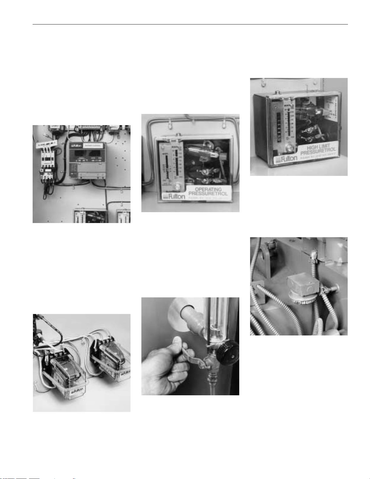
49-G 1/01
Operation
Boiler Controls
a) Flame safeguard burner control–
This is the main control in the panel
box. The programmer in conjunction
with a sensing device, either a flame
rod or an ultra violet scanner,"supervises" the ignition sequence - proves
the flame is satisfactory - and finally
"monitors" the established flame.
Should any fault occur, either during
the ignition sequence or during normal
running, the programmer will immediately go to "lock-out" and the burner
will shut down.
b) Low Water Cut-Off--probe type–
Cuts off the unit when water level is
too low after a 3 second time delay to
avoid nuisance shut downs. As a
standard feature, Fulton boilers are
equipped with ASME CSD-1 Code
controls which include a manual reset
feature on the burner low water cut
off relay and ASME CSD-1 Code
controls also feature an independent
second low water cut off relay. Press
the low water reset button and the
boiler will start.
CAUTION
Do not tamper with the safety features of the low water safety cut
out.
c) Pressure Relief Valve– limits
maximum operating pressure of the
boiler.
d) Operating Steam Pressure
Control– located in the control panel
box and connected to the steam pressure gauge assembly by means of a
copper tube. The pressure control regulates the on/off cycle of the burner,
shutting the burner off when maximum
pressure is reached and switching on
when the steam pressure falls below a
predetermined level.
e) Sight Glass Isolation Valves--
The brass sight glass isolation valves
are equipped with an internal ball
check. In the event that a sight glass
should break, the ball will seat, preventing the discharge of steam and
water. The brass valve stem must be
opened fully to enable this feature. If
the valve is in any other position than
full open, the ball will not seat. For
added safety all Fulton boilers are
equipped with gauge glass protectors.
f) High limit pressure control– located in the control panel box and connected to the steam pressure gauge
assembly by means of a copper tube.
The pressure is usually set 10 to 15
PSI (.703 - 1.054 kg/cm2) above the
operating pressure, but below the
maximum pressure of the pressure
relief valve. If the pressure exceeds
the high limit pressure control setting,
the boiler will automatically shut off.
The high limit pressure control must
be manually reset by depressing the
plunger located on top of the control.
f) Air Pressure Switch– mounted
on the burner scroll, this switch is
operated by the pressure of air entering the burner through the throat of
the scroll. Absence of air, or insufficient pressure, will prevent the
switch completing the circuit, thus
preventing the burner from operating.
WARNING
When stopping the boiler for any
extensive repairs, shut off main disconnect switches on both the boiler
side as well as the feed water side.
NOTE
To ensure that your Fulton Steam
Boiler is kept operating safely and
efficiently, follow the maintenance
procedures set forth in Section 4 of
this manual.
Page 59

Maintenance
4
5-G 1/01
Page 60

51-G 1/01
Page 61

;;;;;;;
;;;;;;;
;;;;;;;
;;;;;
;;;;;
;;;;;
;;;;;
;;;;;
;;
;;
;;
;;
;;
;;
;;
;;
;;
;;
;;
;;
;;
;;
;;
;;
;;
;;
;;
;;
;;
;;
;;
;;
;;
;;
;;
;;
;;;;;;;;;;;;;;;;;;;;
;;;;;;;;;;;;;;;;;;;;
QQQQQQQQQQQQQQQQQQQQ
QQQQQQQQQQQQQQQQQQQQ
¢¢¢¢¢¢¢¢¢¢¢¢¢¢¢¢¢¢¢¢
¢¢¢¢¢¢¢¢¢¢¢¢¢¢¢¢¢¢¢¢
52-G 1/01
Maintenance
Gas Train
Assembly
Burner
Plate
Assembly
Secondary
Air Damper
Top Plate
Assembly
Flue Plate
Cover
Flue Rope
Gasket
Flue Blanket
Lifting Hook(s)
Stainless
Steel Ring
Transformer Scroll
Gaskets
O.P .C.
To
To
H.P .C.
Burner Motor
*
*
Steam Gauge
Assembly
Gauge Glass
Valve
Gauge Glass
And Protector
Water Column
Flue Outlet
Top
Refractory
Feedwater
Inlet
Bottom
Refractory
Blowdown
Outlet
Boiler Runners
(4-30 HP)
Gauge Glass
Valve
Control Box
High Density
Insulation
Outside Jacket
Handhole
Castable
Refractory
Insulation
O.P.C. = Operating Pressure Control
*
H.P.C. = High Pressure Control
*
Page 62

Maintenance
NOTE
To ensure the continued safety and
efficiency of the boiler, the schedule of maintenance outlined in this
section should be adhered to.
WARNING
Prior to the commencement of any
work requiring the removal of cover
plates and the opening of the control panel box, the electrical supply
to the boiler must be disconnected.
Procedure for Cleaning Water
Probes
Clean probe on top of boiler shell
and probes in water column. Make
sure there is no pressure on the
boiler during the removal of the
probes. Remove one probe (using
a 7/8" socket), clean with very fine
emory cloth and replace it before
removing another to assure no
probe mix-ups that would change
the control functions.
For replacement purposes, installed
probe lengths are indicated in the
chart below. For a universally adaptable plug and probe which can be cut
to length in the field to fit all boilers,
order Part No. 2-20-017.
*A = 7-1/4” -- 184 mm
*B = 9-1/4” -- 235 mm
*C = 11-1/4” -- 286 mm
D = 17-1/8” -- 435 mm
*For 4 HP boilers only, water column
probes are 2” shorter.
53-G 1/01
ABCD
Page 63

Flame Rod Adjustment for Fulton
Gas Fired Steam Boilers
a) The flame rod adjustment is made
by loosening the lock nut and turning
the porcelain portion of the flame rod
clockwise or counter clockwise.
Whenever a flame rod is moved, care
should be taken to ensure that the
flame rod does not ground out by
touching the metal surface of the blast
tube assembly. A keyboard display
module can be used to determine
proper signal response. It is necessary to establish pilot so that the main
gas valve will engage. The main
flame should be adjusted to an
acceptable flame signal to ensure continued performance. A poor signal will
result in the boiler flame programmer
going off on safety.
b) A single flame rod is used on 4-15
HP Fulton Boilers, and two flame rods
on 20 and 30 HP. If the boiler has two
flame rods, adjust the flame rod in the
burner plate first, with the outside one
disconnected. After a good pilot signal
is established on the inside flame rod,
then the outside flame rod can be
hooked up and the signal adjusted for
proper responses.
c) If a signal is erratic after adjusting
the flame rod, the main and secondary
air supplies may need adjusting. If a
flame rod is cracked or broken, the
porcelain will have to be replaced to
get a proper signal.
Flame Scanner Adjustments for
Fulton Gas Fired Steam Boilers
a) Flame scanner adjustments are
made with the detectors installed and
the burner running. It is essential to
obtain optimum flame signal detection
for safe and continual operation of the
control relay.
b) If a scanner is inoperable, it may
prove the detector is working and only
an adjustment to the pilot flame is
needed to improve the signal.
c) If the scanner is found to be
defective, replace.
NOTE:
The scanner is located on the outside edge of the burner top plate for
20-60 HP.
d) For the RM7800 Series use a key-
board display module or volt meter,the
flame safeguard will require a 1.25
VDC signal to pull in the main flame.
Then a maximum signal should be
obtained on main flame (5.0 VDC).
e) Adjustments to establish a good
signal may include the following items:
1) Primary and secondary air
adjustments.
2) Increasing the pilot gas through the
pilot gas regulator.
Checking the Stainless Steel
Combustion Ring on Fulton
Gas Fired Steam Boilers
a) The stainless steel combustion
ring in Fulton gas fired boilers
(50-60 HP only) are designed to bring
quick and effective flame transfer to
the fire wall. The ring should fit
securely and tight against the furnace
wall for best results.
b) The ring should be inspected for
distortion in the event of poor combustion which could result in flame
failures.
54-G 1/01
Maintenance
Stainless
Steel
Combustion
Ring
Primary
Air Gate
Gas Head
Flame
Rod(s)
Scanner
Location
(20–60 HP)
*
Scanner
(4–15 HP)
Burner
Plate
Secondary
Air Gate
Blast Tube
Viewing Port
Burner
Viewing Port
Blast Tube
Top Plate
Air Deflector
If Applicable
*
Page 64

Furnace Refractory Replacement
Procedure
a) Remove the burner plate and top
plate assembly up and out of the scroll
assembly.
b) Remove the stainless steel combustion ring from the furnace
(50 and 60 HP only).
c) Remove the clean-out plugs from
the bottom sides of the boiler.
4-15 HP boilers have one clean out
plug located at the bottom of the boiler
directly below the panel box. 20-60
HP boilers have one clean out plug
located at the bottom of the boiler to
the right side of the panel box. 10-30
HP Energypak Boilers have one clean
out to the right of the lower right side
hand hole and one clean out to the
right of the rear bottom blow down.
d) Break off the top holding clips that
were used to keep the refractory in
position during shipping. The 4-50 HP
boilers also have holding clips beneath
the top refractory. There is no need to
cut the holding clips located beneath
the top refractory as the refractory may
be rotated to avoid these clips during
installation of the lower refractory. The
60- HP boiler has welded flat bars
beneath the top refractory. These bars
will have to be cut to change the lower
refractory. Rewelding of the bars will
be required prior to installation of the
top refractory. For the lower refractory
you will also need to break off the top
holding clips that were used to keep
the refractory in position during shipment.
e) Break up the top and/or bottom
refractories and remove the pieces
from the boiler through the clean-out
plugs.
NOTE
If only the top refractory is to be
changed, the bottom refractory
need not be broken.
f) Round and bevel the outer edges of
the new refractories.
g) The bottom refractory has the
largest hole, while the top refractory
has the smallest.
h) Lower the bottom refractory down
the furnace with wire fastened around
the refractory in three positions. When
the refractory is close to position, it can
be tipped by maneuvering the wire to
drop it flat on the holding clips. If the
refractory will not tip, it may have to be
removed and again rounded and
beveled.
i) Install the top refractory in the same
manner as the bottom refractory.
When installed the outer edges must
be sealed with insulcrete - a castable
refractory mix available from the
Fulton factory.
It is not necessary to reinstall the shipping clips.
j) Install the stainless steel combustion ring, (50-and 60 HP only) burner
assembly, and clean out plug.
k) normal operation can be resumed
immediately.
55-G 1/01
Maintenance
Gas Train
Assembly
Air
Deflector
Gas Orifice
Assembly
Stainless Steel
Combustion
Chamber
Ring
Stainless Steel Ring
Supporting Clips
Holding Clips For
Shipping Only
Stainless Steel
Supporting Clips
Top Castable
Refractory
Bottom
Castable
Refractory
Holding Clips For
Shipping Only
Stainless Steel
Supporting Clips
Page 65

56-G 1/01
Recommended Daily
Maintenance Schedule
a) The following procedures should be
carried out daily. They are designed to
prevent the build up of scale, silt, or
sludge in the bottom of the boiler and
in the pipes leading to the water
gauge. In addition to these procedures, the advice of a water treatment
supplier should be sought and followed. An ASME Section VIII blow off
receptacle must be provided for the
appropriate pressure.
b) Blow down the boiler each
morning by starting the boiler and
generating not more than 10 PSI
(.703 kg/cm2) of steam. Turn on tap
water to blow-off separator, then
open the boiler blow off valve for
approximately 10 seconds, then
close the valve. Shut off tap water
to blow-off separator.
Blow Down Boiler Daily. Shown is the
blow down "Y" valve.
NOTE
If the boiler is being operated automatically on a time clock, the blow
off operation may be done once
during the working day and once at
the end of the day when at 10 PSIG
or less.
c) Blow down water column each
morning when boiler is at 10 PSI (.703
kg/cm2) by opening the water column
and the water gauge blow off valves
for approximately 5 seconds, then
close the valves.
Blow down water column each morning
by opening the water column and the
water gauge blow-off valves.
d) If the feed water is being treated by
compounds, make sure that this treatment is carried out carefully and
according to the manufacturer's
instructions.
NOTE
Fulton recommends that the feedwater treatment should be added
between the pump and the boiler.
e) When first starting the boiler each
day, make sure ignition and burner are
working properly.
f) Check water level in sight glass.
g) Check to be sure feed water pump
is working.
h) For float type water level control,
blow-down float chamber.
Recommended Weekly
Maintenance Schedule
a) Check that the low water cut-off
relay is operating correctly in the
following manner:
1) Make sure that the boiler is cool
with little or no pressure showing on
the steam pressure gauge.
2) With the burner operating, open the
boiler blow off valve. When the water
drops below the required level (note
the level in the water gauge glass) the
burner should shut off; this is when the
water level falls below the low water
electrode in the water column assembly and/or the boiler shell. Manual
reset of the low water relay is required.
Recommended Monthly
Maintenance Schedule
WARNING
Make sure main power switch is off
before starting work.
a) Clean the water gauge glass.
CAUTION
Do not clean the gauge or gauge
glass while pressurized or in operation.
1) Clean the water gauge glass using
a commercial non-abrasive glass
cleaner. Use diluted acids such as
hydrochloric (muriatic) acid when regular cleaners do not seem to work. Do
not use wire brushes or any other
abrasive materials which could scratch
the glass. If any leakage is evident,
replace the gaskets.
Clean Glass; Replace Gaskets If
Leaking
2) Always replace the high impact
plastic gauge glass protector which is
standard on all Fulton Boilers.
b) Clean water pump strainers.
c) Check scanner or flame rod and
ignition electrodes.
d) Check starter contacts. Burned or
pitted contacts should be replaced.
Do not use sand paper or file to clean.
e) Clean water traps and strainers in
fuel lines.
f) Check operation of all steam traps
on condensate return system.
Maintenance
Page 66

57-G 1/01
Maintenance
g) Remove brass pipe plug at the
cross connection below water column
and clean nipple into boiler. Boiler
must be cold and water level below
pipe.
Remove plug at cross section; clean
nipple to boiler.
Recommended Semi-Annual
Maintenance Schedule
a) Cleaning the gas burner
assembly
1) Disconnect the gas head from the
burner by disconnecting the union.
Remove the burner plate screws. For
4-15 HP boilers with scanner, disconnect scanner from burner plate.
Withdraw the burner assembly and
clean the flame rod and ignition electrode.
2) Check that the settings of the
flame rod, if applicable, and ignition
electrode correspond to those in the
illustration below.
3) Reassemble the burner assembly
and check the flame rod setting or
scanner setting.
4) Check the combustion efficiency of
the burner and adjust if necessary.
5) Clean probe on top of boiler shell
and probes in water column. There
must be no pressure on the boiler during the removal of the probes.
6) Check refractories for soot or
breakage and inspect the stainless
steel ring (50 and 60 HP only).
7) With the boiler under no more
than 15 PSI pressure, check that the
steam safety valve is operating by
lifting the lever.
b) Drain condensate tank and clean
tank by flushing with hose. Check
float valve operation.
c) Check electrical controls and
motors for correct operation.
d) Check water pump for correct
operation.
e) Shut off the boiler completely
and drain.
f) Remove the hand holes and
inspect the interior of the vessel for
scale or sludge deposits. The
amount of deposits will indicate the
efficiency of the water treatment being
used. The frequency of the inspection
will depend on the condition of the
water side of the boiler.
Inspect hand holes for scale or sludge
buildup.
Test
Pressure
Tapping
Flame Rod
Orifice
Pipe
Grounding
Fins
Gas Burner Ignition
Electrode gap setting is same on 4 - 100 HP units
whether Flame Rod or Scanner is utilized.
Ignition Electrode
Ignition Electrode
Holder
Burner
Plate
Gap to Pipe
1/8" ±1/16"
(Ignition Gap)
Gap to Pipe
1/8" ±1/16"
Page 67

g) Replace hand hole gaskets
using the following procedure:
1) Remove the hand hole assembly
using a 1-1/4" tee handle wrench or
1-1/4" 1/2" drive socket wrench.
Removing hand hole assembly with a
Tee Handle Wrench
2) Remove the old gasket and thor-
oughly clean the surface on the boiler
and the plate.
3) Fit the hand hole assembly as
follows:
a) Place the gasket on the hand hole
plate and ensure that it is seating correctly. Do not use any grease, lubri-
cant, or adhesive.
b) Position the plate in the boiler. Set
the yoke and tighten the securing nut
sufficiently enough to provide a snug
fit. Verify the position of the plate in the
boiler, then make it hand tight and then
snug with wrench about 1/4 turn. Do
not compress excessively.
Illustration shows correct pressure on
gasket.
c) If the gasket leaks while pressure is
being built up, tighten only enough to
stop leakage.
Never tighten more than necessary to
prevent leakage. Excessive tightening
may shorten the life of the gasket.
Illustration shows over compressed
gasket.
d) Refill the boiler with fresh water.
NOTE
After a new Fulton Boiler has been
in operation for several months,
pieces of burned metal will be
found in the space at the bottom of
the boiler. These pieces of metal are
the remains of a light gauge metal
form which was used during manufacture for forming the boiler insulation. This is a normal condition and
does not affect the efficiency or the
life of the boiler in any way.
Recommended Annual
Maintenance Schedule
a) Have combustion (CO2, O2, CO)
and input checked by responsible personnel.
b) Dirty flues can cause air flow
restrictions resulting in poor combustion and loss of efficiency.
Clean flues as follows:
1) Remove the burner and flue
cover plate.
2) Wire brush flue passages.
Wire brushing the flue passages.
3) Remove clean out plugs at lowest
part of unit and clean the bottom of
combustion chamber.
Removing clean out plugs.
4) Remove all soot from the top, and
from the clean out plugs at the bottom
with a vacuum cleaner.
5) Replace clean out plugs carefully
so as not to damage insulation and
replace burner and flue cover plates.
c) Flush boiler out if necessary. See
Section 2 for proper procedure for
"Cleaning the Pressure Vessel."
d) Provide annual inspection by a
qualified ASME Boiler inspector.
Maintenance
Remove burner and flue cover plate
58-G 1/01
Page 68

59-G 1/01
Maintenance
Troubleshooting
a) The following trouble shooting
guide will assist in the diagnosis and
the correction of minor field problems. It contains instructions and
information necessary to locate and
isolate possible troubles which
occur during normal operation. It
should be used in conjunction with
the unit wiring diagram and the
component literature provided in
Section 7 of this manual.
b) The following lists cover the most
common troubles that may occur on
the Fulton gas fired boilers. Refer to
left hand column of the chart to
locate the problem. Determine
which cause, listed in the center column, that represents the problem by
performing the corrective action as
listed in the right hand column titled
“REMEDY”.
Troubleshooting Gas-Fired Boilers
Problem Cause Remedy
Ignition Failure 1. Power Supply Check fuse or circuit breaker. Reset or
replace, as necessary.
2. Ignition Electrodes Check electrodes for carbon buildup and
clean if necessary. Check for proper adjustment. Readjust
if necessary. Check for cracks in porcelain. If found,replace.
3. Transformer Check voltage between transformer leads at
terminal block to be sure transformer is being powered.
4. Flame Safeguard Check voltage between ignition terminal and neutral.
Control Check must be made before control locks out on safety.
If no power, replace control.
5. Faulty Air Switch Check for bad air switch by jumpering the two air switch
leads at the terminal block. If the boiler starts and runs
with these terminals jumpered, the air switch should
be replaced.
6. Gas Valve Sticking Check for dirt in valve or orifice and clean if necessary.
(Pilot) Check for faulty actuator or valve and replace if necessary.
7. Gas Supply* Check for gas pressure and for intermittent supply
problems. Gas pressure for natural gas should be
3-1/2" W.C. plus fan pressure at the elbow to the
burner and 7" to 11" W.C. at the head of the train.
8. Loose wire connection Check connections to all components.
Flame Failure 1. Power Supply Check fuse or circuit breaker. Reset or replace, as
necessary.
2. Gas Supply* Check for gas pressure and for intermittent supply
problems. Gas pressure for natural gas should be
3-1/2" W.C. plus fan pressure at the elbow to the
burner and 7" to 11" W.C. at the head of the train.
3. Ignition Electrodes Check electrodes for carbon buildup and clean
if necessary. Check for proper adjustment.
Readjust if necessary. Check for cracks in
porcelain; if found, replace.
4. Primary Air Adjustment Check air adjustment. Air may be blowing flame
away from flame rod.
* For natural gas fired boilers. Refer to the test fire sheet for all other fuels.
Page 69

60-G 1/01
Problem Cause Remedy
Flame Failure 5. Flame Rod Adjustment Check flame rod for carbon buildup and clean if
or UV Scanner necessary. Check flame rod adjustment via a
display module. Flame signal should be 5 VDC.
Check for cracks in porcelain. If found, replace.
Check for dirt on flame scanner and clean.
Check for proper location of detector.
6. Flame Safeguard Control Check voltage at terminal leading to main gas valve.
If no power, replace the control.
7. Loose wire at fuel Tighten wiring connections.
valve circuit
8. Contact open on air Adjust to proper setting.
safety switch
9. Scanner wiring reversed Change to correct terminals.
at panel box.
Burner Cut-Off 1. Power Supply Check fuse or circuit; reset or replace, as necessary.
2. Gas Supply Check to be sure main gas cock is not closed. Check coil
in gas valve with OHM meter. Replace if faulty. Check gas
regulator setting and readjust as necessary. Check inlet
gas pressure and increase or decrease as necessary.
3. Ignition Electrodes Check electrodes for carbon buildup and clean if
necessary. Check for proper adjustment Readjust if
necessary. Check for cracks in porcelain; if found replace.
4. Flame Rod Adjustment Check flame rod for carbon buildup and clean if
or UV Scanner necessary. Check flame rod adjustment via a
display module. Flame signal should be 5 VDC.
Check for cracks in porcelain. If found, replace.
Check for dirt on flame scanner and clean.
Check for proper location of detector.
5. Air Switch Check for bad air switch by jumpering the two air switch
leads at the terminal block. If the boiler starts and runs
with these terminals jumpered, the air switch should
be replaced.
6. Gas Valve Sticking Check for dirt in valve or orifice and clean if necessary.
(Pilot) Check for faulty actuator or valve and replace if necessary.
7. Weak Ampl;ifier Replace.
8. Weak Pilot Adjust to larger pilot by adjusting pilot gas pressure
regulator.
9. Faulty Liquid Level Control Check to see if there is power to terminal number 10
when the sight glass shows the proper water level.
If there is no power at this terminal, the control is bad and
must be replaced.
10. Dirty or defective Clean or replace.
UV Scanner.
Maintenance
Page 70

61-G 1/01
Maintenance
Problem Cause Remedy
Poor Combustion 1. Refractories Check refractories to see if they are plugged with soot or
broken in pieces. Clean or replace as necessary.
2. S.S. Ring Check to be sure ring is present and fits tight against the
furnace wall (50-100 HP).
3. Primary Air Check air adjustment. Air/fuel mixture may be off. Open
Adjustment primary air so fire is to outside wall of furnace.
4. Secondary Air Check main air adjustment to see if it is loosened up.
Adjustment Adjust as necessary and tighten plate in position. Check
CO2and O2levels.
5. Draft Check draft with a gauge. Draft should be a -.02 " to -.04"
W.C. with burner off or -.04" to -.06" when operating. May
need to install a barometric damper.
6. Dirty Flue Check flue for carbon buildup or blockage. Clean flue
passages with brush.
7. Negative Room Pressure Make sure no exhaust fans are running in the boiler room.
Burner back fires 1. Refractories Check refractories to see if they are plugged with soot or
broken in pieces. Replace as necessary.
2. Ignition Electrodes Check electrodes for carbon buildup and clean if
necessary. Check for proper adjustment Readjust if
necessary. Check for cracks in porcelain; if found replace.
3. Flame rode adjustment Check flame rod for carbon buildup and clean if
or UV Scanner necessary. Check flame rod adjustment via a
display module. Flame signal should be 5 VDC.
Check for cracks in porcelain. If found, replace.
Check for dirt on flame scanner and clean.
Check for proper location of detector.
5. Draft Check draft with a gauge. Draft should be a -.02 " to -.04"
W.C. with burner off or -.04" to -.06" when operating. May
need to install a barometric damper.
6. Negative Room Pressure Make sure no exhaust fans are running in the boiler room.
Boiler will not 1. Gas Supply Check gas pressure coming into gas train. If low,
maintain pressure contact gas company. Should be 7" to 11" W.C. Check
coil in gas valve with AMP meter. Replace if bad.
Check gas regulator setting and readjust as necessary.
2. Dirty Flue Check flue for carbon buildup or blockage. Clean flue
passages with brush.
3. Pressuretrol Disconnect all power to the controller. Disconnect the
wires from the controller. Put an OHM meter between the
switch terminals. Lower the set point of the controller.
Switch should make. Raise the set point and recheck
with OHM meter. Switch should break. If the controller
operates improperly, replace it.
Page 71

62-G 1/01
Maintenance
Problem Cause Remedy
Boiler will not 4. Scale Built up in boiler Refer to Section 2 “Pressure Vessel Cleaning”.
maintain pressure
5. Refractories Check refractories to see if they are cracked or
broken in pieces. Replace as necessary.
6. Steam traps Check traps to see if they are clean or replace as
blowing through. necessary.
7. Boiler size. Boiler may be undersized.
Boiler is Surging 1. Steam traps blowing Check traps to see if they are clean or replace as
through necessary.
2. Perc (cleaning solvent Clean boiler with washing soda per
in boiler) instruction manual.
3. Scale build-up or lime Call water treatment professional and consult factory.
deposits.
4. Too much compound in Dump return tank and flush system. Have water tested by
system (water treatment) water treatment company.
5. Too much water Have water tested by water treatment company.
softener (high PH)
6. Too much of a load Check total equipment horsepower required against
horsepower of boiler being used. Decrease amount of
equipment being used at one time.
7. Boiler new (not Clean per instructions in instruction manual.
cleaned).
Boiler Rumbles and 1. Draft problem Check draft with a gauge. Draft should be a -.02 " to -.04"
Pulsates W.C. with burner off or -.04" to -.06" W.C. when
operating. May need to install a barometric damper.
2. Too much primary air (See primary air adjustment)
Boiler pushing water 1. Steam Traps Check traps. Clean or replace as necessary.
with the steam
2. Too much boiler Dump return tank and flush system . Have
compound water tested by water treatment company.
Pump will not cut off 1. Dirty Probes Clean or replace as necessary.
2. Relay failed Make sure relay is plugged in tightly. If so,
replace water level relay.
3. Ground Connection Check for tightness and clean.
Page 72

63-G 1/01
Maintenance
Problem Cause Remedy
Pump runs but does 1. Vapor locking of pump. Allow system to cool down, check steam traps
not put water into boiler and check to be sure return lines are not insulated. Check
return tank temp. If it is above 180 deg. F, (82 deg. C)
vapor locking of pump will occur. Inspect check valves.
Clean and replace as needed. Replace pump with
multistage centrifugal good for 250 degrees F (121 deg.C).
2. Impeller Adjustment Check for impeller wear and adjust per component
information in instruction manual (Burks only).
3. Back pressure on pump Need to install repair kit on pump.
4. Plugged feed water Check and clean or replace as necessary.
nipple
Water pump will not 1. Scale on probes. Check and clean or replace as necessary.
come on at times.
2. Bad Pump Contactor Check to see if contactor is being powered.
Check to see if contactor coil is pulling in. Replace if
necessary.
3. Bad Pump Motor Check the incoming power to the pump to be
sure it is receiving power. If power is present but motor
does not run, replace it.
Low Fuel pressure 1. Gas pressure regulator Check and replace.
Boiler Flooding 1. Pump does not Dirty Probes. Clean or replace as necessary.
shut off
2. Relay failed Make sure relay is plugged in tightly. If so,
replace water level relay.
3. Ground Connection Check for tightness and clean.
4. Vacuum created with As the boiler cools off, it pulls water from the system
boiler off. piping. To prevent this, add a 1/4" check valve on the
steam gauge assembly piping, which closes under
pressure and opens under vacuum.
Page 73

Parts
5
6-G 1/01
Page 74

ICS (FB-A) Classic & ICX (FB-F) Edge manual update:
For all new ICS (FB-A) Classic boilers manufactured 2018 and after, the following updates have
occurred:
The ICX (FB-F) Edge model boiler has been discontinued.
The ICS (FB-A) Classic is now configured as follows:
• The ICS (FB-A) Classic boilers initially configured as natural gas or propane boilers are
configured with the ICX (FB-F) Edge second flue gas pass rib heat transfer pattern and
cannot be converted to fire #2 oil. These boilers will also require use of the Edge
cleanout brush in lieu of the standard. The Edge cleanout brush part number is 2-60-
000155.
• The ICS (FB-A) Classic boilers initially configured as #2 oil boilers or combination natural
gas/propane and #2 oil boilers are configured with the further spaced Classic second
flue gas pass rib heat transfer pattern. These boilers will also require use of the Classic
cleanout brush. The Classic cleanout brush part number is 2-60-000112.
Page 75

66-G 1/01
Parts
Spare Parts
a) It is important that the correct
replacement part is fitted to your
Fulton Gas Fired Steam Boiler.
b) When ordering replacement or
spare parts, make sure that the full
information given in the Parts List is
supplied, together with the following
details as shown on your boiler
identification plate:
1. Boiler Number
2. Boiler Type
3. Electrical Specifications
Note:
The policy of Fulton Boiler
Works, Inc. is one of continuous
improvement, and therefore, we
reserve the right to change
prices, specifications, and equipment without notice.
Page 76

Parts
5-60-100 Instruction Manual, Fuel-Fired 2 0.91
5-60-165 Certification Papers
5-60-164 Boiler Documentation for Export Boilers
Boiler Shell Parts
5-12-004 Furnace Refractory 8" OD x 2" ID (9.5 HP Top) 10 4.55
5-12-005 Furnace Refractory 8" OD x 21/2" ID (4 HP Gas Top - Old Style) 10 4.55
5-12-006 Furnace Refractory 8" OD x 3" ID (9.5 HP Bottom ) 10 4.55
5-12-007 Furnace Refractory 10" OD x 3" ID (4-10 HP Top) 18 8.18
5-12-008 Furnace Refractory 10" OD x 31/2" ID (15 HP Top) 18 8.18
5-12-009 Furnace Refractory 10" OD x 5" ID (4-15 HP Bottom) 18 8.18
5-12-010 Furnace Refractory 15" OD x 51/2" ID (20 HP Top) 35 15.91
5-12-011 Furnace Refractory 15" OD x 6" ID (30 HP Top) 35 15.91
5-12-012 Furnace Refractory 15" OD x 7" ID (20 & 30 HP Bottom) 35 15.91
5-12-015 Furnace Refractory 24" OD x 8" ID (40 - 60 HP Top) 125 56.82
5-12-016 Furnace Refractory 24" OD X 10" ID (40- 60 HP Bottom) 125 56.82
5-12-017 Furnace Refractory 30" OD x 91/2" ID (80 HP Top) 225 102.27
2-12-000 Furnace Cement- 2 Ib. can 2 0.91
2-12-001 Furnace Cement - 8 Ib. can 8 3.64
2-12-002 Furnace Cement - 15 Ib. can 15 6.82
5-10-353 Flue Cover Ring - 4 & 6 & 9.5 HP 19 8.64
5-10-354 Flue Cover Ring -10 HP 20 9.09
5-10-355 Flue Cover Ring - 15 HP 20.5 9.32
5-10-357 Flue Cover Ring - 20 HP 21 9.55
5-10-359 Flue Cover Ring - 30 HP 25 11.36
5-10-360 Flue Cover Ring - 40-60 HP 40 18.18
5-12-001 Bottom Cleanout Access Plate with Plug 4-30 HP 10 4.55
5-12-002 Bottom Cleanout Access Plate with Plug 40-60 HP 20 9.09
5-12-003 Square Cleanout Plug (Not for Series E) 15 6.82
2-12-064 Flexitalic (HHG) Extra Heavy High Pressure 0.5 0.23
2-12-088 Blue Max HHG 0.05 0.02
5-10-800 Handhole Welding Patch 4-60 HP 1.1 0.5
2-12-004 Handhole Gasket 4-60 HP 0.05 0.02
2-11-105 HandholeYoke 1.5 0.68
2-11-100 3 x 4 Handhole Cover 4-10 HP (White) 2 0.91
2-11-101 3 x 4 Handhole Cover 15 HP (Red) . 2 0.91
2-11-102 3 x 4 Handhole Cover 20 HP (Green) 2 0.91
2-11-103 3 x 4 Handhole Cover 30 HP (Yellow) 2 0.91
2-11-104 3 x 4 Handhole Cover 40-100 HP (Blue) 2 0.91
4-11-010 10 HP Handhole Assembly (White) 7 3.18
4-11-012 15 HP Handhole Assembly (Red) 7 3.18
4-11-014 20 HP Handhole Assembly (Green) 7 3.18
4-11-016 30 HP Handhole Assembly (Yellow) 7 3.18
4-11-018 40 -60 HP Handhole Assembly (Blue) 7 3.18
2-12-504 Blanket Insulation (Sq. ft.) 0.5 0.23
5-21-300 Steel Jacket 4 HP - No Holes Cut 80 36.36
5-21-301 Steel Jacket 6 HP - No Holes Cut 80 36.36
Approx. Approx.
Part No. Description Net Weight Net Weight
(lbs.) (kgs.)
67-G 1/01
Replacement Parts Listing (available from authorized Fulton Representative)
Page 77

Parts
5-21-302 Steel Jacket 10 HP - No Holes Cut 100 45.45
5-21-303 Steel Jacket 15 HP - No Holes Cut 115 52.27
5-21-304 Steel Jacket 20 HP - No Holes Cut 125 56.82
5-21-305 Steel Jacket 30 HP - No Holes Cut 125 56.82
5-21-306 Steel Jacket 40-60 HP - No Holes Cut 125 56.82
5-21-5064 Bottom Handhole Funnel 4 & 6 HP 6.5 2.95
5-21-5066 Bottom Handhole Funnel 10 HP 6.5 2.95
5-21-5068 Bottom Handhole Funnel 15 HP 6.5 2.95
5-21-5070 Bottom Handhole Funnel 20 HP 6.5 2.95
5-21-5072 Bottom Handhole Funnel 30 HP 6.5 2.95
5-21-5074 Bottom Handhole Funnel 40 & 60 HP 6.5 2.95
5-21-5063 Top Handhole Funnel 4 & 6 HP 6.5 2.95
5-21-5065 Top Handhole Funnel 10 HP 6.5 2.95
5-21-5067 Top Handhole Funnel 15 HP 6.5 2.95
5-21-5069 Top Handhole Funnel 20 HP 6.5 2.95
5-21-5071 Top Handhole Funnel 30 HP 6.5 2.95
5-21-5073 Top Handhole Funnel 40 - 60 HP 6.5 2.95
123 Bottom Funnel Repair Kits 4-15 HP 9.5 4.32
123 Bottom Funnel Repair Kits 20-30 HP 9.5 4.32
123 Bottom Funnel Repair Kits 40-60 HP 9.5 4.32
123 Top Funnel Repair Kits 4-15 HP 9.5 4.32
123 Top Funnel Repair Kits 20-30 HP 9.5 4.32
123 Top Funnel Repair Kits 40-60 HP 9.5 4.32
2-21-053 6" Stack Connection 4-10 HP 6.5 2.95
2-21-054 8" Stack Connection 15 HP 7 3.18
2-21-055 10" Stack Connection 20 HP 7.5 3.41
2-21-056 12" Stack Connection 30-60 HP 8 3.64
2-21-058 6" Stack to Pipe Adaptor 4-10 HP 6.5 2.95
2-21-059 8" Stack to Pipe Adaptor 15 HP 7 3.18
2-21-060 10" Stack to Pipe Adaptor 20 HP 8 3.64
2-21-061 12" Stack to Pipe Adaptor 30-60 HP 9 4.09
2-12-501 Castable Block Mix - per Ib. (10 Ibs. min.)-Use for top of bottom handhole up
2-12-498 Castable Block Mix - 25 Ib. bag -Use for top of bottom handhole up
2-12-502 Kast Set - per Ib. (10 Ibs. minimum) - Use for making refractories
2-12-500 Insulcrete - per Ib. (10 Ibs. min.) - Use for top of bottom handhole down
2-12-497 Insulcrete - 50 Ib. bag - Use for top of bottom handhole down
5-12-020 Kaowool Sleeve for Bottom Funnel 0.9 0.41
4-12-018 Kaowool Insulation per sq. ft.
2-12-507 Kaowool (panels) 7"
2-21-015 Buckeye Stamping for Bottom Handhole 4-100 HP 1 0.45
2-21-092 Buckeye Stamping for Upper Handhole 4-15 HP 1 0.45
2-21-093 Buckeye Stamping for Upper Handhole 20-100 HP 1 0.45
2-23-171 Touch Up Paint - MICA Spray 1 0.45
4-23-014 Mica Paint - Quart 2 0.91
4-23-044 Mica Paint - Gallon 7.8 3.55
2-12-504 TIW Filler Insulation per sq ft
Approx. Approx.
Part No. Description Net Weight Net Weight
(lbs.) (kgs.)
68-G 1/01
Page 78

Parts
Burner Assembly - Parts (Common)
2-40-605 1/3 HP 115/230/60/1 Burner Motor 3450 RPM 21 9.55
2-40-606 1/3 HP 230/460/60/3 Burner Motor 3450 RPM 20 9.09
2-40-603 1/3 HP 110/220/50/1 Burner Motor 2850 RPM 25 11.36
2-40-770 1/3 HP 380/50/3 Burner Motor 2850 RPM 28 12.73
2-40-608 3/4 HP 115/230/60/1 Burner Motor 3450 RPM 25 11.36
2-40-611 3/4 HP 230/460/60/3 Burner Motor 3450 RPM 22 10
2-40-609 3/4 HP 110/220/50/1 Burner Motor 2850 RPM 28 12.73
2-40-610 3/4 HP 380/50/3 Burner Motor 2850 RPM 22 10
2-40-613 1.5 HP 115/230/60/1 Burner Motor 3450 RPM 40 18.18
2-40-614 1.5 HP 110/220/50/1 Burner Motor 2850 RPM 45 20.45
2-40-615 1.5 HP 230/460/60/3 Burner Motor 2850/3450 RPM 31 14.09
2-40-771 1.5 HP 380/50/3 Burner Motor 2850 RPM 48 21.82
2-40-773 2.0 HP 380/50/3 Burner Motor 2850 RPM 48 21.82
2-40-616 2.0 HP 115/230/60/1 Burner Motor 3450 RPM 43 19.55
2-40-618 2.0 HP 230/460/60/3 Burner Motor 3450 RPM 33 15
2-40-617 2.0 HP 110/220/50/1 Burner Motor 2850 RPM 48 21.82
2-12-014 Pyrex Plate Glass 1 " - 4 -100 HP 0.1 0.05
2-45-025 Bakelite Terminal 90° for Electrode 0.05 0.02
2-45-026 Bakelite Terminal Straight for Electrode 0.05 0.02
2-45-017 Ignition Wire - per foot 0.01 0
2-11-116 Burner Scroll Casting - 9.5 HP 14 6.36
2-11-123 Burner Scroll Casting- 4-15 HP 30 13.64
5-20-059 Burner Scroll Casting - 20 HP 35 15.91
5-20-060 Burner Scroll Casting - 30 HP 40 18.18
5-20-061 Burner Scroll Casting - 40, 50 & 60 HP 50 22.73
Burner Fans:
Size HP Applicable Fuel Hz.
2-30-407 5-1/2 x 1-1/2 x 5/8 4 HP Propane or Nat. Gas 50/60 HZ 1.40 0.64
6 HP Propane 50/60 HZ 1.40 0.64
2-30-410 6-1/4 x 1-1/2 x 5/8 6 HP Combination or Natural Gas 50/60 HZ 1.60 0.73
2-30-412 7 x 1-1/2 x 5/8 9.5-10 HP Propane or Nat. Gas 50/60 HZ 2.00 0.91
2-30-414 7-11/16 X 1-1/2 x 5/8 15-20 HP Propane or Nat. Gas 50/60 HZ 2.30 1.05
2-30-418 8-3/8 x 2 x 5/8 30 HP Propane or Nat. Gas 50/60 HZ 3.15 1.43
2-30-421 8-3/8 x 2-1/2 x 1 40-50 HP Propane or nat. Gas 50/60 HZ. 3.00 1.36
60 HP Propane or nat. Gas 50/60 HZ. 3.00 1.36
*When ordering burner fans, check for the correct part number on the back of the fan plate.
Burner Assembly - Gas
2-40-082 Ignition Transformer - Gas 115/60 9.5 4.32
2-40-083 Ignition Transformer - Gas 240/60 9.5 4.32
2-40-084 Ignition Transformer - Gas 120/50 10.3 4.68
2-40-085 Ignition Transformer - Gas 220/50 10.2 4.64
2-45-026 Straight Bakelite Terminal 0.03 0.01
4-45-010 Ignition Cable with 90° Bakelite Terminal 0.5 0.23
4-45-012 Flame Rod Cable with 90° Bakelite Terminal 0.5 0.23
2-20-019 Ignition Electrode 0.4 0.18
2-20-020 Flame Rod 0.4 0.18
Approx. Approx.
Part No. Description Net Weight Net Weight
(lbs.) (kgs.)
69-G 1/01
Page 79

Parts
2-30-118 Air Switch 4-100 HP 0.72 0.33
5-20-019 Burner Plate Gas - 4 HP 1 0.45
5-20-007 Burner Plate Gas - 6 & 10 HP 1 0.45
5-20-055 Burner Plate Gas - 9.5 HP 2 0.91
5-20-013 Burner Plate Gas - 15 & 20 HP 1 0.45
5-20-018 Burner Plate Gas - 30-60 HP 1 0.45
2-11-112 Air Deflector - Gas - 6 & 10 HP 11 5.00
2-11-075 Air Deflector - Gas - 9.5 HP 11 5.00
2-11-113 Air Deflector - Gas -15 HP 11 5.00
7-20-088 Air Deflector - Gas - 20 HP 24 10.91
7-20-090 Air Deflector - Gas - 30 HP 24 10.91
7-20-092 Air Deflector - Gas 40 - 60 HP 45 20.45
2-40-533 Gas Pressure Switch High-Low 3.25 1.48
2-40-211 Gas Pressure Switch - Low 4.9 2.23
2-40-212 Gas Pressure Switch - High 4.8 2.18
2-30-298 1/2" Pilot Gas Valve (4-100 HP) 1.5 0.68
2-30-301 1 " Main Gas Valve - V48A 3.2 1.45
2-30-302 1-1/4 " Main Gas Valve - V48A 4 1.82
2-30-303 1-1/2" Main Gas Valve - V48A 4.5 2.05
2-30-312 1-1/2" Gas Valve V5055A 4 1.82
2-30-313 2" Gas Valve V5055A 9.2 4.18
2-40-249 Gas Valve Body - P.O.C V5055C 1" 5 2.27
2-40-252 Gas Valve Body - P.O.C V5055C 1-1/4" 5.1 2.32
2-40-253 Gas Valve Body - P.O.C V5055C 1-1/2" 4.7 2.14
2-40-254 Gas Valve Body - P.O.C V5055C 2" 9.3 4.23
2-40-214 Actuator for 2", 2-1/2" and 3" Valve Body 13.70 6.23
2-40-220 Actuator for 2", 2-1/2" and 3" Valve Body w/Proof of Closure Switch 12.8 5.82
2-30-400 3/4" Vent Valve - 120V Normally Open 3.2 1.45
2-30-401 1" Vent Valve - 120V Normally Open 4.3 1.95
2-30-402 1-1/4" Vent Valve - 120V Normally Open 4.7 2.14
2-30-305 3/4" Solenoid GasValve 1.8 0.82
2-30-306 1" Solenoid Gas Valve 3.9 1.77
2-30-307 1-1/4'' Solenoid Gas Valve 3.9 1.77
2-30-308 1-1/2" Solenoid Gas Valve 4.4 2.00
2-30-198 1/8" Gas Cock (Pet Cock) 0.25 0.11
2-30-111 1/2" Pilot Gas Cock 0.6 0.27
2-30-112 3/4" Main Gas Cock 1.5 0.68
2-30-113 1" Main Gas Cock 2 0.91
2-30-114 1-1/4 " Main Gas Cock 3 1.36
2-30-115 1-1/2 " Main Gas Cock 4.8 2.18
2-30-116 2" Main Gas Cock 4.8 2.18
2-30-021 1" Lubricated Gas Cock 5 2.27
2-30-022 1-1/4" Lubricated Gas Cock 6.5 2.95
2-30-013 1-1/2" Lubricated Gas Cock 7 3.18
2-30-012 2" Lubricated Gas Cock 10 4.55
Approx. Approx.
Part No. Description Net Weight Net Weight
(lbs.) (kgs.)
70-G 1/01
Page 80

Parts
2-30-102 1/2" Gas Pressure Regulator RV 48 0.7 0.32
2-30-104 1" Gas Pressure Regulator - RV 53 1.5 0.68
2-30-105 1-1/4 " Gas Pressure Regulator - RV 61 5 2.27
2-30-106 1-1/4" Gas Pressure Regulator - RV 81 5 2.27
2-30-107 1-1/2"Gas Pressure Regulator - RV 81 4.8 2.18
2-30-108 2" Gas Pressure Regulator - RV 91 8.3 3.77
2-20-002 CSA Air Gas Mixing Valve 1 0.45
7-20-060 Natural Gas Orifice - 4 HP Pre 2/89 3/4" 2 0.91
7-20-050 Natural Gas Orifice - 4 HP - Post 2/89 1" 2 0.91
7-20-051 Natural Gas Orifice - 6 HP 2 0.91
7-20-078 Natural Gas Orifice - 9.5 HP 2 0.91
7-20-052 Natural Gas Orifice -10 HP 2 0.91
7-20-023 Natural Gas Orifice - 15 HP - Post 2/89 1" 2 0.91
7-20-053 Natural Gas Orifice -15 HP - Pre 2/89 1-1/4" 2.5 1.14
7-20-054 Natural Gas Orifice - 20 HP 3 1.36
7-20-055 Natural Gas Orifice - 30 HP 3 1.36
7-20-265 Natural Gas Orifice - 40 HP 3.5 1.59
7-20-056 Natural Gas Orifice - 50 HP 3.5 1.59
7-20-057 Natural Gas Orifice - 60 HP 3.5 1.59
7-20-060 Propane Orifice - 4 HP - Pre 2/89 3/4" 2 0.91
7-20-030 Propane Orifice - 4 HP - Post 2/89 1" 2 0.91
7-20-061 Propane Orifice - 6 HP 2 0.91
7-20-062 Propane Orifice - 10 HP 2 0.91
7-20-033 Propane Orifice - 15 HP - Post 2/89 1" 2 0.91
7-20-063 Propane Orifice -15 HP - Pre 2/89 1-1/4" 2.5 1.14
7-20-064 Propane Orifice - 20 HP 3 1.36
7-20-065 Propane Orifice - 30 HP 3 1.36
7-20-275 Propane Orifice - 40 HP 3.5 1.59
7-20-066 Propane Orifice - 50 HP 3.5 1.59
7-20-067 Propane Orifice - 60 HP 3.5 1.59
2-30-177 Propane Spring RV48 0.05 0.02
2-30-178 Propane Spring RV53 0.05 0.02
2-30-179 Propane Spring RV61 0.05 0.02
2-30-180 Propane Spring RV81 0.05 0.02
2-30-181 Propane Spring RV91 0.05 0.02
7-30-001 Top Plate Assembly - 4 HP - Natural Gas 10 4.55
7-30-002 Top Plate Assembly - 6 & 10 HP - Natural Gas 15 6.82
5-30-001 Top Plate Assembly 9.5 HP - Natural Gas 15 6.82
7-30-003 Top Plate Assembly - 15 HP - Natural Gas 15 6.82
7-30-004 Top Plate Assembly - 20 HP - Natural Gas 35 15.91
7-30-005 Top Plate Assembly - 30 HP - Natural Gas 35 15.91
7-30-006 Top Plate Assembly - 40, 50 & 60 HP - Natural or Propane Gas 65 29.55
7-30-020 Top Plate Assembly - 4 HP - Propane Gas 10 4.55
7-30-021 Top Plate Assembly - 6 & 10 HP - Propane Gas 15 6.82
7-30-022 Top Plate Assembly - 15 HP - Propane Gas 15 6.82
7-30-023 Top Plate Assembly - 20 HP - Propane Gas 35 15.91
7-30-024 Top Plate Assembly - 30 HP - Propane Gas 35 15.91
Approx. Approx.
Part No. Description Net Weight Net Weight
(lbs.) (kgs.)
71-G 1/01
Page 81

Parts
7-30-025 Burner Plate Assembly - 4 HP - Natural Gas 7 3.18
7-30-026 Burner Plate Assembly - 6 HP - Natural Gas 8 3.64
7-30-123 Burner Plate Assembly - 9.5 HP Natural Gas 8 3.64
7-30-027 Burner Plate Assembly - 10 HP - Natural Gas 8 3.64
7-30-028 Burner Plate Assembly - 15 HP - Natural Gas 8 3.64
7-30-029 Burner Plate Assembly - 20 HP - Natural Gas 10 4.55
7-30-030 Burner Plate Assembly - 30 HP - Natural Gas 10 4.55
7-30-031 Burner Plate Assembly - 40, 50 HP - Natural Gas 12 5.45
7-30-032 Burner Plate Assembly - 60 Hp - Natural Gas 12 5.45
7-30-053 Burner Plate Assembly - 4 HP - Propane Gas 7 3.18
7-30-054 Burner Plate Assembly - 6 HP - Propane Gas 8 3.64
7-30-055 Burner Plate Assembly - 10 HP - Propane Gas 8 3.64
7-30-056 Burner Plate Assembly - 15 HP - Propane Gas 8 3.64
7-30-057 Burner Plate Assembly - 20 HP - Propane Gas 10 4.55
7-30-058 Burner Plate Assembly - 30 HP - Propane Gas 10 4.55
7-30-059 Burner Plate Assembly - 40, 50 HP - Propane Gas 12 5.45
7-30-060 Burner Plate Assembly - 60 HP - Propane Gas 12 5.45
7-54-1000 Gas Train Assembly- 4 HP - Natural Gas 20 9.09
7-54-1001 Gas Train Assembly - 6 HP- Natural Gas 23 10.45
7-54-1002 Gas Train Assembly -10 HP - Natural Gas 23 10.45
7-54-1003 Gas Train Assembly - 15 HP - Natural Gas - 1" 23 10.45
7-54-1004 Gas Train Assembly - 20 HP - Natural Gas - 1-1/4" 27 12.27
7-54-1005 Gas Train Assembly - 30 HP - Natural Gas 27 12.27
7-54-1006 Gas Train Assembly - 40 - 50 HP - Natural Gas 70 31.82
7-54-1007 Gas Train Assembly- 60 HP- Natural Gas 70 31.82
7-54-1050 Gas Train Assembly - 4 HP - Propane Gas 20 9.09
7-54-1051 Gas Train Assembly - 6 HP - Propane Gas 25 11.36
7-54-1052 Gas Train Assembly -10 HP - Propane Gas 25 11.36
7-54-1053 Gas Train Assembly -15 HP - Propane Gas 25 11.36
7-54-1054 Gas Train Assembly - 20 HP - Propane Gas 30 13.64
7-54-1055 Gas Train Assembly - 30 HP - Propane Gas 30 13.64
7-54-1056 Gas Train Assembly - 40 - 50 HP - Propane Gas 70 31.82
7-54-1057 Gas Train Assembly - 60 HP - Propane Gas 70 31.82
Water Column
5-20-022 Fulton Water Column Bottle Casting -4-100 HP 20 9.09
2-30-151 MM 150 Pump Control 25 11.36
2-30-193 MM 150 - M/R Control 25 11.36
2-30-152 MM 150 HD Assembly 25 11.36
2-30-192 MM 150-M-HD M/R Head 25 11.36
2-12-125 MM 150-14 Gasket 0.05 0.02
2-30-136 MM 157 Pump Control and Low Water Cutoff 39.7 18.05
2-30-137 MM 53-2 Boiler Feeder and Low Water Cutoff 38.5 17.5
2-45-144 MM Mercury Switch - 2 Wire 1 0.45
2-45-143 MM Mercury Switch - 3 Wire 1 0.45
2-30-149 Water Gauge Glass Valves w/Ball Checks 1.5 0.68
2-30-047 Try Cocks 0.4 0.18
2-12-065 8-5/8" Extra Heavy Gauge Glass 0.05 0.02
2-12-008 9-1/4 Water Gauge Glass - standard 0.05 0.02
2-12-007 9-1/4" Extra Heavy Gauge Glass 0.1 0.05
2-12-017 9-1/4" Water Gauge Glass -Corning 0.05 0.02
Approx. Approx.
Part No. Description Net Weight Net Weight
(lbs.) (kgs.)
72-G 1/01
Page 82

Parts
2-12-018 10" Water Gauge Glass- MM 0.06 0.03
2-12-071 12" Water Gauge Glass 0.07 0.03
2-12-063 14"Water Gauge Glass 0.08 0.04
2-30-155 Conbraco 250# GG Valve w/Ball Check (9.5 HP) 1.5 0.68
2-12-020 Brass Water Gauge Glass Gasket 0.0018 0
2-12-019 Rubber Water Gauge Glass Gasket 0.004 0
2-12-080 Teflon Water Gauge Gaskets 0.01 0
2-35-514 Brass Packing Nut for Gauge Glass Valve 0.1 0.05
2-30-330 Gauge Glass Protector Rods 0.04 0.02
2-12-022 Lucite Gauge Glass Guard for 9-1/4" Glass 0.4 0.18
2-12-024 Lucite Gauge Glass Guard for 10" Glass 0.5 0.23
2-12-021 Lucite Gauge Glass Guard for 12" Glass (53MM) 0.06 0.03
2-12-204 Lucite Gauge Glass Guard - 9.5 HP 0.045 0.02
4-21-010 Water Column Electrode Basket & Cover 0.5 0.23
4-30-050 Set of four (4) Water Level Probes & Plugs - 4 HP 1.3 0.59
4-30-052 Set of four (4) Water Level Probes & Plugs - 6-60 HP 1.3 0.59
4-30-042 Set of 3 Water Column Probes 0.8 0.36
2-20-010 Pump Off Probe - 7-1/4 " 0.2 0.09
2-20-011 Pump On Probe - 9-1/4" 0.2 0.09
2-20-012 Low Water Probe in Water Column -11-1/4” 0.3 0.14
2-20-017 Low Water Probe in Boiler- 17-1/8” 0.5 0.23
2-21-012 Probe Cover - 2" 1 0.45
2-21-013 Probe Cover - 4" 1 0.45
2-30-398 1/4"Male-Female Ball Valve for Water Column 0.6 0.27
2-40-021 Probe Basket 0.05 0.02
Panel Box Parts
2-40-420 Fulton Pump Relay-120V 0.5 0.23
2-40-421 Fulton Burner Relay - 120V 0.5 0.23
2-40-422 Base for Fulton Pump Relay 0.25 0.11
2-40-423 Base for Fulton Burner Relay 0.25 0.11
2-40-405 Fulton Pump Relay - 220v 0.5 0.23
2-40-406 Fulton Burner Relay - 220v 0.5 0.23
2-12-090 Spring Retainer for burner/pump relay 0.001 0
2-40-403 IDlDO-120VRelay 2 0.91
2-40-402 IGIDO - 120V Relay 2 0.91
2-40-400 IGlDO-A-120VRelay 2 0.91
2-40-401 ID2DO - 220V Relay 2 0.91
4-45-050 Set of three (3) Coils for ID or IG Type Relay 1 0.45
4-45-051 Set of three (3) Coils ID2D0 - 220V 1 0.45
2-40-131 General Purpose Relay (Ice Cube) - AB 0.8 0.36
2-40-096 Base for Ice Cube Relay 0.1 0.05
2-45-091 On/Off Switch 0.05 0.02
2-45-092 Manual Reset Switch 0.05 0.02
2-45-090 Night Switch for two (2) Pressuretrols 0.05 0.02
2-40-552 4" Alarm Bell 1 0.45
2-40-551 120V Transformer for Bell 1 0.45
2-40-550 220V Transformer for Bell 1 0.45
Approx. Approx.
Part No. Description Net Weight Net Weight
(lbs.) (kgs.)
73-G 1/01
Page 83

Parts
2-45-106 Green Panel Box Indicating Light - 120V 0.1 0.05
2-45-107 White Panel Box Indicating Light -120V 0.1 0.05
2-45-108 Amber Panel Box Indicating Light - 120V 0.1 0.05
2-45-110 Red Panel Box Indicating Light -120V 0.1 0.05
2-45-112 Green Panel Box Indicating Light - 220V 0.1 0.05
2-45-115 White Panel Box Indicating Light - 220V 0.1 0.05
2-45-116 Amber Panel Box Indicating Light - 220V 0.1 0.05
2-45-114 Red Panel Box Indicating Light - 220V 1 0.45
2-45-412 AB Green Panel Light 120 V - NEMA 4 0.02 0.01
2-45-413 AB Amber Panel Light 120 V - NEMA 4 0.02 0.01
2-45-411 AB Red Panel Light 120 V - NEMA 4 0.02 0.01
2-45-410 AB White Panel Light 120 V - NEMA 4 0.02 0.01
2-40-567 Motor Contactor - AB - 100 - A09ND3- 120V - 4-60 HP 0.8 0.36
2-40-568 Motor Contactor - AB - 100 - A09NA3- 220V - 4-60 HP 0.8 0.36
2-40-565 Overload - AB - BSB 16 0.45 0.2
2-40-657 Overload - AB - BSB 15 0.45 0.2
2-40-648 Overload - AB - BSB 22 0.45 0.2
2-40-571 Overload - AB - BSB 30 0.45 0.2
2-40-575 Overload - AB - BSC 10 0.45 0.2
2-40-643 Overload - AB - BSC 15 0.45 0.2
2-40-652 Overload - AB - BSC 24 0.45 0.2
2-40-572 Overload - AB - BSB 42 0.45 0.2
2-40-573 Overload - AB - BSB 60 0.45 0.2
2-40-574 Overload - AB - BSB 80 0.45 0.2
2-40-566 Overload - AB - BSB 90 0.45 0.2
2-40-200 Motor Starter Relay -120V - 20 AMP 0.6 0.27
2-40-202 Motor Starter Relay - 120V - 30 AMP 0.5 0.23
2-40-201 Motor Starter Relay - 220V - 20 AMP 0.4 0.18
2-40-203 Motor Starter Relay - 220V - 30 AMP 0.5 0.23
4-40-050 Night Heating Pressuretrol Set Up 3.5 1.59
2-40-227 Pressuretrol L404A - 2-15 PSI 1.7 0.77
2-40-228 Pressuretrol L404A - 5-50 PSI 2 0.91
2-40-229 Pressuretrol L404A - 10-150 PSI 2 0.91
2-40-230 Pressuretrol L404A - 20-300PSI 2.7 1.23
2-40-231 Pressuretrol L404C - 2-15 PSI 2 0.91
2-40-232 Pressuretrol L404C - 5-50 PSI 2 0.91
2-40-233 Pressuretrol L404C - 10-150 PSI 2 0.91
2-40-234 Pressuretrol L404C - 20-300 PSI 2.7 1.23
2-40-161 Flame Scanner (Mini-Peeper) 0.5 0.23
2-40-260 RM7895A Programmer 20-50 HP - 120 V 2 .91
2-40-262 RM7800M Programmer 60-100 HP - 120 V 2.5 1.14
2-40-265 7 Second Prepurge Timer 0.1 0.05
2-40-266 30 Second Prepurge Timer 0.1 0.05
2-40-267 60 Second Prepurge Timer 0.1 0.05
2-40-268 RM7800 Amplifier - For Flame Rod 0.3 0.14
2-40-269 RM7800 Amplifier - For UV Amp 0.2 0.09
Approx. Approx.
Part No. Description Net Weight Net Weight
(lbs.) (kgs.)
74-G 1/01
Page 84

Parts
2-40-161 Mini Peeper For All 7800 0.5 0.23
2-40-270 Base For All 7800 0.5 0.23
2-40-272 Display Module for 7800 Controls English (Also Available in Spanish) 0.5 0.23
2-40-247 Remote Mounting Bracket for 7800 0.65 0.3
2-40-248 Extension Cable
2-40-261 EC7830A Programmer 220/50 2 0.91
2-40-276 Timer 7 for EC7830/50 0.1 0.05
2-40-273 Timer 30 for EC7830/50 0.1 0.05
2-40-274 UV - Amplifier for EC7830/50 0.2 0.09
Boiler Trim
5-35-100 9.5 HP Steam Orifice 2 0.91
2-30-396 1" Spring Loaded Check Valve - 200# 2.55 1.16
2-30-397 1-1/4" Spring Loaded Check Valve - 200# 3.8 1.73
2-30-019 1/4" Ball Valve - 200# 0.6 0.27
2-30-008 1/2" BallValve-200# 0.7 0.32
2-30-027 3/4" BallValve-200# 1.4 0.64
2-30-026 1" Ball Valve - 200# 1.75 0.8
2-30-001 1" MxF Ball Valve 200# 2 0.91
2-30-017 1-1/4" Ball Valve - 200# 3.1 1.41
2-30-018 1-1/2" Ball Valve - 200# 4.7 2.14
2-30-025 2" Ball Valve - 200# 6.35 2.89
2-30-208 3" Ball Valve - 200# 18 8.18
2-30-391 1"Y Type Blowdown Valve - 200# 4 1.82
2-30-392 1-1/4" Y Type Blowdown Valve - 200# 5.5 2.5
2-30-393 1-1/2" Y Type Blowdown Valve - 200# 8.4 3.82
2-30-007 1" Quick Action Blowdown Valve 13 5.91
2-30-014 1-1/4" Quick Action Blowdown Valve 14 6.36
2-30-023 1-1/2" Quick Action Blowdown Valve 23 10.45
2-40-133 Timer for Automatic Blowdown System 0.8 0.36
2-30-386 1" Motorized Valve for Automatic Blowoff 9.8 4.45
2-30-387 1-1/4" Motorized Valve for Automatic Blowoff 10.7 4.86
2-30-403 1-1/2" Motorized Valve for Automatic Blowoff 12.6 5.73
2-30-1066 1/2" Steam Solenoid Valve - 120V 2.3 1.05
2-30-122 3/4" Steam Solenoid Valve - 120V 2.5 1.14
2-30-146 1" Steam Solenoid Valve - 120V 4.5 2.05
2-30-147 1-1/4 " Steam Solenoid Valve - 120V 4.9 2.23
2-30-148 1-1/2" Steam Solenoid Valve - 120V 6.3 2.86
2-30-214 3/4" 15# Series 19 V-Stamped Safety Valve 1 0.45
2-30-215 1" 15# Series 19 V-Stamped Safety Valve 1.1 0.5
2-30-216 1-1/4" 15# Series 19 V-Stamped Safety Valve 1.85 0.84
2-30-016 1-1/2" 15# Series 19 V-Stamped Safety Valve 2 0.91
2-30-217 2" 15# Series 19 V-Stamped Safety Valve 2.5 1.14
2-30-062 1/2"-100# Safety Valve 1.2 0.55
2-30-063 1/2"-125# Safety Valve 1.3 0.59
2-30-064 3/4"-15# Safety Valve 1 0.45
2-30-065 3/4"-30# Safety Valve 1.8 0.82
2-30-067 3/4"-75# Safety Valve 3.2 1.45
Approx. Approx.
Part No. Description Net Weight Net Weight
(lbs.) (kgs.)
75-G 1/01
Page 85

Parts
2-30-068 3/4"-100# Safety Valve 2 0.91
2-30-069 3/4"-125# Safety Valve 2 0.91
2-30-070 3/4"-150# Safety Valve 1.4 0.64
2-30-071 3/4"-200# Safety Valve 5.1 2.32
2-30-073 3/4"-300# Safety Valve 2.35 1.07
2-30-074 1"-15# Safety Valve 1.1 0.5
2-30-075 1"-75# Safety Valve 4 1.82
2-30-076 1"-100# Safety Valve 4.1 1.86
2-30-077 1"-125# Safety Valve 4.1 1.86
2-30-078 1"-150# Safety Valve 4.1 1.86
2-30-079 1"-200# Safety Valve 4 1.82
2-30-081 1"-300# Safety Valve 5 2.27
2-30-082 1-1/4 "-15# Safety Valve 1.85 0.84
2-30-083 1-1/4"-100# Safety Valve 6.6 3
2-30-084 1-1/4"-125# Safety Valve 6.75 3.07
2-30-085 1-1/4"-150# Safety Valve 6.8 3.09
2-30-086 1-1/2"-15# Safety Valve 2 0.91
2-30-087 1-1/2"-100# Safety Valve 12.4 5.64
2-30-088 1-1/2"-125# Safety Valve 10.9 4.95
2-30-089 1-1/2"-150# Safety Valve 12.3 5.59
2-35-518 1/4" Steel Pigtail Syphon for Steam Gauge Assembly- Long 0.6 0.27
2-30-202 Pressure & Temp Gauge 1 0.45
2-30-326 0-30 PSI Steam Pressure Gauge 0.5 0.23
2-30-334 0-60 PSI Steam Pressure Gauge 0.5 0.23
2-30-333 0-200 PSI Steam Pressure Gauge 0.5 0.23
2-30-332 0-300 PSI Steam Pressure Gauge 0.5 0.23
2-30-327 0-600 PSl Steam Pressure Gauge 0.5 0.23
2-12-025 Teflon Disc for 1" Y Valve 0.2 0.09
2-11-015 Brass Seat for 1" Y Valve 0.1 0.05
2-12-026 Teflon Disc for 1-1/4 " Y Valve 0.5 0.23
2-11-016 Brass Seat for 1-1/4 " Y Valve 0.1 0.05
2-12-027 Teflon Disc for 1-1/2" Y Valve 0.2 0.09
2-11-017 Brass Seat for 1-1/2" Y Valve 0.1 0.05
2-12-028 Teflon Disc for 2" Y Valve 0.2 0.09
2-11-018 Brass Seat for 2" Y Valve 0.1 0.05
Test Equipment/Tools
2-40-090 Test Leads 0.6 0.27
2-40-215 Microampmeter - W136 2 0.91
2-60-100 Jr. Amprobe - Y25 1 0.45
2-60-102 Pocket Draft Meter 1 0.45
2-60-103 All Purpose Draft Meter 3 1.36
2-60-104 CO Tester-Gas 15 6.82
2-60-105 CO Tubes 0.25 0.11
2-60-106 StackThermometer 4 1.82
2-60-108 SmokeTester-Oil 2 0.91
2-60-110 Fisher Gauge - 50 PZ 1 0.45
2-60-112 Flue Cleanout Brush 0.8 0.36
2-60-247 Flue Brush - Pipe Type - 2-1/2" - 100 HP 1 0.45
2-60-248 Flue Brush - Pipe Type - 2" - 80 HP 1 0.45
Approx. Approx.
Part No. Description Net Weight Net Weight
(lbs.) (kgs.)
76-G 1/01
Page 86

Parts
5-10-397 Tee Handle Wrench 2.7 1.23
2-20-110 Fan Puller - 5/8" Hub 2 0.91
2-20-115 Fan Puller - 1" Hub 2 0.91
Barometric Controls
2-30-092 6" MGI 4, 6 & 10 HP - Gas 3 1.36
2-30-095 8" MG1 15 HP - Gas 4 1.82
2-30-097 10" M&MG2 20 HP - Oil, Gas, Comb 8 3.64
2-30-098 12" M&MG2 30 HP - Oil, Gas, Comb. 12 5.45
2-30-099 14" M&MG2 50 - 100 HP - Oil, Gas, Comb. 16 7.27
2-30-0415 16" M&MG2 25 11.36
Spare Parts Kits
4-50-000001 Spare Parts Kit No. 1 4-30 BHP Gas Consists of: 4 1.82
Qty Part No. Description
6 2-12-000004 Handhole Gaskets
1 2-12-000017 9-1/4" Gauge Glass
2 2-12-000019 Water Gauge Glass Rubber
2 2-12-000020 Water Gauge Glass Fiber
1 2-20-000019 Ignition Electrode
1 2-20-000020 Flame Rod
1 5-10-000397 Tee Handle Wrench
1 4-30-000052 Set of (4) Plugs and Probes
4-50-000002 Spare Parts Kit No. 2 50-100 BHP Gas 4 1.82
6 2-12-000004 Handhole Gaskets
1 2-12-000017 9-1/4" Gauge Glass
2 2-12-000019 Water Gauge Glass Rubber
2 2-12-000020 Water Gauge Glass Fiber
1 2-20-000019 Ignition Electrode
1 5-10-000397 Tee Handle Wrench
1 4-30-000052 Set of (4) Plugs and Probes
2-12-515 Burner Plate Gasket 4 HP Gas 0.05 0.02
2-12-516 Burner Plate Gasket 6-20 HP Gas 0.05 0.02
2-12-517 Burner Plate Gasket 30-100 HP Gas 0.06 0.03
2-12-023 Screws (11) 0.001 0.00
2-12-513 Bottom Cleanout Gasket Only 0.5 0.23
2-12-514 Combination Gasket 0.05 0.02
4-12-100 Flue Cover Plate Gasket - 4 HP 1.5 0.68
4-12-102 Flue Cover Plate Gasket - 6 HP 1.5 0.68
4-12-104 Flue Cover Plate Gasket -10 HP 1.5 0.68
4-12-106 Flue Cover Plate Gasket -15 HP 1.8 0.82
4-12-108 Flue Cover Plate Gasket - 20 HP 2 0.9
4-12-110 Flue Cover Plate Gasket - 30 HP 2 0.91
4-12-112 Flue Cover Plate Gasket - 40-60 HP 2.5 1.14
2-12-210 1/4" Braided Rope Gasket 4-100 HP - price per foot 0.25 0.11
0.00
2-12-077 Handhole Funnel Gasket 20-100 HP Top 0.05 0.02
2-12-078 Handhole Funnel Gasket 4-15 HP Top 0.05 0.02
2-12-079 Handhole Funnel Gasket 4-100 HP Bottom 0.05 0.02
Approx. Approx.
Part No. Description Net Weight Net Weight
(lbs.) (kgs.)
77-G 1/01
Page 87

Parts
2-12-528 Scroll Gasket - 4 HP 1 0.45
2-12-529 Scroll Gasket - 6-15 HP 1 0.45
2-12-530 Scroll Gasket- 20-30 HP 1 0.45
2-12-531 Scroll Gasket- 40-60 HP 1 0.45
2-12-537 Stack Extension Gasket 6" 4-10 HP 1 0.45
2-12-538 Stack Extension Gasket 8" 15 HP 1 0.45
2-12-539 Stack Extension Gasket 10" 20 HP 1 0.45
2-12-540 Stack Extension Gasket 12" 30-60 HP 1 0.45
2-12-518 Top Plate Gasket - 4 HP (Old Style) 1 0.45
2-12-519 Top Plate Gasket - 4-15 HP 1 0.45
2-12-520 Top Plate Gasket - 20-30 HP 1 0.45
2-12-521 Top Plate Gasket - 40-60 HP 1 0.45
4-12-522 9.5 HP Gas, Oil, & Comb Gasket Kit 5 2.27
4-12-500 4-15 HP Gas, Oil, & Comb Gasket Kit 5 2.27
4-12-506 20-30 HP Gas, Oil, & Comb Gasket Kit 6 2.73
4-12-512 40-60 HP Gas, Oil, & Comb Gasket Kit 10 4.55
See the following component assembly drawings to assist with parts identification.
Approx. Approx.
Part No. Description Net Weight Net Weight
(lbs.) (kgs.)
78-G 1/01
Page 88

79-G 1/01
Parts
Page 89

Parts
Part No.* Burner Motor
2-40-605 1/3 HP 115/230/60/1 3450 4-15
2-40-606 1/3 HP 230/460/60/3 3450 4-15
2-40-603 1/3 HP 110/220/50/1 2850 4-15
2-40-770 1/3 HP 380/50/3 2850 4-15
2-40-608 3/4 HP 115/230/60/1 3450 20-30
2-40-611 3/4 HP 230/460/60/3 3450 20-30
2-40-609 3/4 HP 110/220/50/1 2850 20-30
2-40-771 1.5 HP 380/50/3 2850 40-60
2-40-613 1.5 HP 115/230/60/1 3450 40-60
2-40-615 1.5 HP 230/460/60/3 3450 40-60
2-40-614 1.5 HP 110/220/50/1 2850 40-60
*The correct part number is located on the burner motor.
Part No. Burner Scroll Casting
2-11-123 Burner Scroll Casting 4-15
5-20-059 Burner Scroll Casting 20
5-20-060 Burner Scroll Casting 30
2-11-126 Burner Scroll Casting 40 -60
(1)
RPM HP
(2)
HP
Part No.
(8)
(9)
(6)
HP
HP
50-100
4-30
Nat. Gas Orifice LP Gas Orifice
7-20-050 7-20-030 4
7-20-051 7-20-061 6
2-20-078 consult factory 9.5
7-20-052 7-20-062 10
7-20-023 7-20-033 15
7-20-054 7-20-064 20
7-20-055 7-20-065 30
7-20-265 7-20-275 40
7-20-056 7-20-066 50
7-20-057 7-20-067 60
Part No. Air Switch
2-30-118 4-100
Part No. Flame Detectors HP
2-40-161 Scanner for 7800 Series
2-20-020 Flame Rod
(7)
Part No.* Burner Fan
2-30-407 5-1/2 x 1-1/2 x 5/8 LP/N.Gas 50/60 4
2-30-410 6-1/4 x 1-1/2 x 5/8 N.Gas 50/60 6
2-30-412 7 x 1-1/2 x 5/8 LP/N. Gas 50/60 9.5-10
2-30-414 7-11/16 X 1-1/2 x 5/8 LP/N. Gas 50/60 15-20
2-30-418 8-3/8 x 2 x 5/8 LP/N. Gas 50/60 30
2-30-421 8-3/8 x 2-1/2 x 1 LP/N. Gas 50/60 40-50.
2-30-425 9 -3/16 X 2-1/2 x 1 LP/N. Gas 50/60 60
*The correct part number is located on the back of the fan plate.
Part No. Ignition Transformer
2-40-082 120/60/1
2-40-083 240/60/1
2-40-084 120/50/1
2-40-085 240/50/1
Part No. Air Deflector
2-11-112 Air Deflector 4-10
2-11-075 Air Deflector 9.5
2-11-113 Air Deflector 15-20
7-20-090 Air Deflector 30
7-20-092 Air Deflector 40-60
(3)
Fuel HZ HP
LP 50/60 6
(4)
(5)
HP
(11)
(10)
(12)
(13)
(14)
HP
HP
4-60
40-100
4-100
Part No. Burner Plate
5-20-019 Gas Burner Plate 4
5-20-007 Gas Burner Plate 6-10
5-20-055 Gas Burner Plate 9.5
5-20-013 Gas Burner Plate 15-20
5-20-018 Gas Burner Plate 30-60
Part No. Air Gate
5-20-017 Air Gate 4-10
5-20-012 Air Gate 15
5-20-011 Air Gate 20-30
5-20-066 U.K. Air Gate 40-100
Part No. Electrode Parts HP
2-20-019 Ignition Electrode
2-20-033 Ignition Electrode - VMP
2-12-014 Pyrex Plate Glass 1"
80-G 1/01
Page 90

-G 1/01
Parts
Gas Burner
Ignition Assembly
Gas Burner Components
81
Page 91

82-G 1/01
Parts
Gas Head Assemblies
Part No. Complete Gas Head Assembly HP
7-54-1000 Natural Gas 4
7-54-1001 Natural Gas 6
7-54-1002 Natural Gas 10
7-54-1003 Natural Gas 15
7-54-1004 Natural Gas 20
7-54-1005 Natural Gas 30
7-54-1006 Natural Gas 40-50
7-54-1007 Natural Gas 60
7-54-1050 Propane Gas 4
7-54-1051 Propane Gas 6
7-54-1052 Propane Gas 10
7-54-1053 Propane Gas 15
7-54-1054 Propane Gas 20
7-54-1055 Propane Gas 30
7-54-1056 Propane Gas 40-50
7-54-1057 Propane Gas 60
Gas Train Components
Part No. Description HP
2-30-113 Main Gas Manual Shut Off Valve (1) 4-15
2-30-114 Main Gas Manual Shut Off Valve 20
2-30-115 Main Gas Manual Shut Off Valve 30-50
2-30-116 Main Gas Manual Shut Off Valve 60
2-30-104 Main Gas Pressure Regulator (2) 4-15
2-30-105 Main Gas Pressure Regulator 20
2-30-107 Main Gas Pressure Regulator 30-50
2-30-108 Main Gas Pressure Regulator 60
2-30-301 Main Automatic Gas Valve (3) 4-15
2-30-302 Main Automatic Gas Valve 20
2-30-303 Main Automatic Gas Valve 30-50
2-40-220 Main Automatic Gas Valve Actuator
w/Proof of Closure (4) 60-100
2-40-254 Main Automatic Gas Valve Body (5) 60
2-30-198 Leak Test Valve (6) 4-100
2-40-533 High/Low Gas Pressure Switch (7) 60-100
Part No. Description HP
2-30-113 Final Manual Shut-off Valve (8) 4-15
2-30-114 Final Manual Shut-off Valve 20
2-30-115 Final Manual Shut-off Valve 30-50
2-30-116 Final Manual Shut-off Valve 60
2-30-111 Pilot Gas Manual Shut-off Valve (9) 4-100
2-30-102 Pilot Gas Pressure Regulator (10) 4-100
2-30-298 Pilot Gas Automatic Shut-off Valve (11) 4-100
Page 92
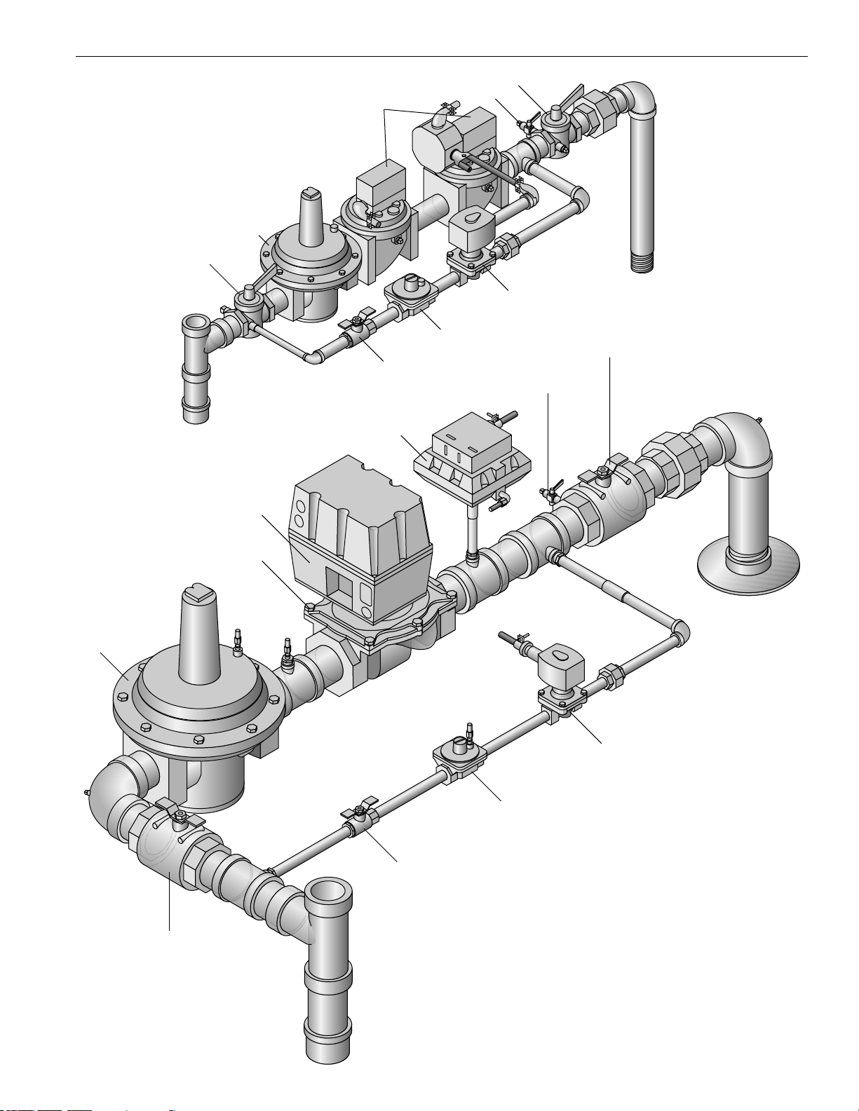
83-G 1/01
Parts
Gas Head Assembly (CSD-1)
4 to 50 HP
Gas Head Assembly (CSD-1)
60 HP
2
1
8
3
6
11
4
5
2
10
8
9
6
7
11
10
9
1
Page 93

84-G 1/01
Parts
Water Level
Relay
Contactor/
Overload–3 Phase
(Upon Request) or
Starter Relay–1 Phase
For Feed Water
Pump Motor
Flame
Safe Guard/
Burner Control
Low Limit
Pressuretrol
(Optional)
Operating Pressuretrol
Terminal Block Low Water
Safety Relays
Low Water
Manual
Reset Switch
4-50 HP:
1 Phase Motor
Starter Standard
60 HP:
3 Phase Contactor/
Overload Standard
3 Phase Available
On 4-50 HP As Option
Power
On/Off Switch
High Limit
Pressuretrol
With
Manual Reset
Panel Box Parts
Part No. Relays HP
2-40-420 Fulton Pump Relay - 120V 4-100
2-40-421 Fulton Burner Relay - 120V 4-100
2-40-422 Base for Fulton Pump Relay 4-100
2-40-423 Base for Fulton Burner Relay 4-100
2-40-405 Fulton Pump Relay 220V 4-100
2-40-406 Fulton Burner Relay 220V 4-100
2-40-403 IDlDO-120V Relay 4-100
2-40-402 IGIDO - 120V Relay (manual reset) 4-100
2-40-400 IGlDO-A-120V Relay 4-100
2-40-401 ID2DO - 220V Relay 4-100
Part No. Switches HP
2-45-091 On/Off Switch 4-100
2-45-092 Manual Reset Switch 4-100
2-45-090 Night Switch for two (2) Pressuretrols 4-100
Part No. Motor Starter Relays (Single Phase) HP
2-40-200 Motor Starter Relay - 120V - 20 AMP 4-50
2-40-202 Motor Starter Relay - 120V - 30 AMP 4-50
2-40-201 Motor Starter Relay - 220V - 20 AMP 4-50
2-40-203 Motor Starter Relay - 220V - 30 AMP 4-50
Part No. Flame Safeguard Control HP
2-40-260 RM7895F Programmer 4-50
2-40-262 RM7800M Programmer 60-100
2-40-272* Display Module For 7800 Series Controls 60-100
*Standard on 60-100 HP; optional 4-50 HP.
Part No. Motor Contactors (Three Phase) HP
2-40-568 Contactor -AB -100- A09NA3- 220V 4-60
2-40-567 Contactor- AB -100- A09ND3-120V 4-60
2-40-641 Contactor -AB -100- A12NA3- 220V 80-100
2-40-642 Contactor- AB -100- A12ND3-120V 80-100
2-40-565 Overload - AB - BSB 16
2-40-657 Overload - AB - BSB 15
2-40-648 Overload - AB - BSB 22
2-40-571 Overload - AB - BSB 30
2-40-575 Overload - AB - BSC 10
2-40-643 Overload - AB - BSC 15
2-40-652 Overload - AB - BSC 24
2-40-572 Overload - AB - BSB 42
2-40-573 Overload - AB - BSB 60
2-40-574 Overload - AB - BSB 80
2-40-566 Overload - AB - BSB 90
Note: Contactor Overload depends on motor h.p. and voltage
Part No. Pressuretrols HP
4-40-050 Night Heating Pressuretrol Set Up 4-100
2-40-227 Pressuretrol L404A - 2-15 PSI 4-100
2-40-228 Pressuretrol L404A - 5-50 PSI 4-100
2-40-229 Pressuretrol L404A - 10-150 PSI 4-100
2-40-230 Pressuretrol L404A - 20-300 PSI 4-100
2-40-231 Pressuretrol L404C - 2-15 PSI 4-100
2-40-232 Pressuretrol L404C- 5-50 PSI 4-100
2-40-233 Pressuretrol L404C - 10-150 PSI 4-100
2-40-234 Pressuretrol L404C - 20-300 PSI 4-100
Note: Correct pressuretrol is based on boiler trim pressure.
Page 94

85-G 1/01
Parts
14
12
(Located
In
Boiler)
9
13
11
10
1
2
6
15
8
4
5
3
7
3
Water Column - Parts
Part No. Water Column Bottle Casting (1) HP
5-20-022 Water Column Bottle Casting 4-30
5-20-048 Water Column Bottle Casting 50-100
Part No. Water Gauge Glass (2) HP
2-12-017 9-1/4" Water Gauge Glass - Corning 4-100
2-12-065 8-5/8" Extra Heavy Gauge Glass 9.5
Part No. Water Gauge Glass Trim HP
2-30-149 Water Gauge Glass Valves w/Ball Checks (3) 4-100
2-30-155 Conbraco 250 w/Ball Check (3) 9.5
2-12-020 Brass Water Gauge Glass Gasket (4) 4-100
2-12-019 Rubber Water Gauge Glass Gasket (5) 4-100
2-35-514 Brass Packing Nut for Gauge Glass Valve (6) 4-100
2-30-330 Gauge Glass Protector Rods (7) 4-100
2-12-022 Lucite Gauge Glass Guard -9-1/4" Glass (8) 4-100
2-12-204 Lucite Gauge Glass Guard -8-5/8" Glass (8) 9.5
Part No. Water Level Probes & Plugs HP
2-20-010 *Pump Off Probe - 7-1/4 " (9) 6-100
2-20-011 *Pump On Probe - 9-1/4" (10) 6-100
2-20-012 *Low Water Probe in Water Column-11-1/4" (11) 6-100
2-20-017 Low Water Probe in Boiler- 17-1/8" (12) 6-100
2-21-012 Probe Cover (13) 4-100
2-21-013 Probe Basket (14) 4-100
2-30-398 1/4" Ball Valve for Water Column (15) 4-100
*For 4 HP boilers only, the water column probes are 2” shorter.
Page 95

Warranty
6
8-G 1/01
Page 96

87-G 1/01
Page 97

Standard Warranty for Fulton Boilers
88-G 1/01
Warranty Valid for Models ICS, ICX, ICW, ICXW, VMP, VMPW, FB-A, FB-F, FB-L, FB-S, FB-W
Five (5) Year (60 Months) Material and Workmanship Warranty
The pressure vessel is covered against defective material or workmanship for a period of five (5)
years from the date of shipment from the factory. Fulton will repair or replace F.O.B. factory any
part of the equipment, as defined above, provided this equipment has been installed, operated
and maintained by the buyer in accordance with approved practices and recommendations made
by Fulton. The commissioning agency must also successfully complete and return the equipment
Installation and Operation Checklists to Fulton’s Quality Assurance department. This warranty
covers any failure caused defective material or workmanship; however, waterside corrosion or
scaling is not covered. Therefore, it is imperative that the boiler water management and chemistry
be maintained as outlined in the Installation and Operation Manual.
Parts Warranty
Fulton will repair or replace F.O.B. factory any part of the equipment of our manufacture that is
found to be defective in workmanship or material within one (1) year of shipment from the factory
provided this equipment has been installed, operated and maintained by the buyer in accordance
with approved practices and recommendations made by both Fulton and the component
manufacturers and the commissioning agency has successfully completed and returned the
equipment Installation and Operation Checklists to Fulton’s Quality Assurance department.
General
Fulton shall be notified in writing as soon as any defect becomes apparent. This warranty does
not include freight, handling or labor charges of any kind.
These warranties are contingent upon the proper sizing, installation, operation and maintenance
of the boiler and peripheral components and equipment. Warranties valid only if installed,
operated, and maintained as outlined in the Fulton Installation and Operation Manual.
No Sales Manager or other representative of Fulton other than the Quality Manager or an officer
of the company has warranty authority. Fulton will not pay any charges unless they were preapproved, in writing, by the Fulton Quality Manager.
This warranty is exclusive and in lieu of all other warranties, expressed or implied, including but
not limited to the implied warranties of merchantability and fitness for a particular purpose. Fulton
shall in no event be liable for any consequential or incidental damages arising in any way,
including but not limited to any loss of profits or business, even if the Fulton Companies has been
advised of the possibility of such damages. Fulton’s liability shall never exceed the amount paid
for the original equipment found to be defective.
To activate the warranty for this product, the appropriate commissioning sheets must be
completed and returned to the Fulton Quality Assurance department for review and approval.
9/9/09
Page 98

89-G 1/01
Page 99

Extended Warranty for Fulton Skid Mounted Steam Boilers
90-G 1/01
Warranty Valid for Models ICS, ICX, VMP, FB-A, FB-F, FB-L, FB-S
Ten (10) Year Material and Workmanship Warranty
The pressure vessel is covered against defective material or workmanship for a period of ten (10) years from the date of shipment
from the factory. Fulton will repair or replace at our option, F.O.B. factory any part of the equipment, as defined above, provided this
equipment has been installed, operated and maintained in accordance with the Installation, Operation and Maintenance Manual.
The commissioning agency must also successfully complete and return the equipment Installation and Operation Checklist to
Fulton’s Service Department. This warranty covers any failure caused by defective material or workmanship, however, waterside
corrosion or scaling is not covered. Therefore, it is imperative that the boiler water management and chemistry be maintained as
outlined in the Installation, Operation and Maintenance Manual.
The extended warranty is valid only for steam boilers that are purchased as part of a skid mounted boiler system. Generally, this
system MUST include ALL of the following equipment in order for the warranty to apply.
1. Fulton boiler with model number as listed above.
2. Fulton DA or condensate return system with preheat kit.
3. Fulton blowdown tank/separator
4. Water softener
5. Chemical feed system
6. Automatic surface or bottom blowdown, which must operate to maintain TDS levels as specified in the Installation,
Any deviation or additional equipment specified by Fulton Engineering must be used and maintained per the Installation, Operation
and Maintenance Manual
There is a $1,000 labor allowance for any failed pressure vessel that is covered under the above warranty.
Parts Warranty
Fulton will repair or replace FOB factory any part of the equipment of our manufacture that is found to be defective in workmanship
or material within twelve (12) months of shipment from the factory provided this equipment has been installed, operated and
maintained by the buyer in accordance with approved practices and recommendations made by both Fulton and the component
manufacturers.
General
Fulton shall be notified in writing as soon as any defect becomes apparent. This warranty does not include freight, handling or labor
charges of any kind.
No Sales Manager or other representative of Fulton other than the Quality Manager or an officer of the company has warranty
authority. Fulton will not pay any charges unless they were pre-approved, in writing, by the Fulton Quality Manager.
This warranty is exclusive and in lieu of all other warranties, expressed or implied, including but not limited to the implied warranties
of merchantability and fitness for a particular purpose. Fulton shall in no event by liable for any consequential or incidental damages
arising in any way, including but not limited to any loss of profits or business, even if Fulton has been advised of the possibility of
such damages. Fulton’s liability shall never exceed the amount paid for the original equipment found to be defective.
Conditions of Warranty
Warranties are only valid if the boiler is installed, operated and maintained as outlined in the Installation, Operation and
Maintenance Manual. Fulton shall accept no responsibility if the equipment has been improperly installed, operated or maintained
or if the buyer has permitted any unauthorized modification, adjustment, and/or repairs to the equipment. The use of replacement
parts not manufactured or authorized by Fulton will void any warranty express or implied.
Warranty coverage for all components and equipment in said warranty are not valid unless the boiler is started up by a factory
certified technician. The commissioning agency must successfully complete and return the equipment Installation and Operation
Checklist to Fulton’s Service department.
The boiler must be maintained in accordance with the product manual and annual combustion and maintenance reports must be
produced for warranty consideration.
The warranty is valid for the original installation only in the U.S.A and Canada.
Operation and Maintenance Manual.
08/20/10
Page 100

91-G 1/01
 Loading...