

Page 1
Fulton Steam
Horizontal Boiler
FB-S Series
100-800 Hp
Installation, Operation and Maintenance Manual
Serial # __________________________
Model # __________________________
Fulton Order # __________________________
Sold To __________________________
Job Name __________________________
Date __________________________
The Fulton Companies
972 Centerville Road
Pulaski, NY 13142
Telephone: (315) 298-5121
Facsimile: (315) 298-6390
www.fulton.com
The Fulton Companies*FB-S Series Manual*Version 2010-0820 rev. 3/5/13
Page 1
Page 2

The Fulton Companies*FB-S Series Manual*Version 2010-0820 rev. 3/5/13
Page 2
Page 3

Table of Contents
Introduction
Section 1 – Safety Warnings &
13. Boil-out of new unit
Section 4 – Controls & Burner
Precautions
Section 2 – Description &
Introductions
1. General
2. Specifications & Dimensions
Section 3 – Installation
1. Locating the boiler
2. Boiler room ventilation
3. Flue & chimney requirements
4. Recommended Water Conditions
5. Water Supply
6. Glossary of Water Terms
7. Valves
8. Electrical requirements
9. Gas supply
10. Oil supply
11. Installation check points
12. Cleaning
1. Boiler control panel
2. Burner
Section 5 – Operation
1. Fitting the boiler
2. Starting the burner
3. Daily operating test
4. Blowdown procedure
5. To shutdown the burner
6. Evaporation test
7. Fault finding
Section 6 – Maintenance
1. General
2. Weekly
3. Six monthly
4. Annually
5. Fitting new gasket
Section 7 - Warranty
The Fulton Companies*FB-S Series Manual*Version 2010-0820 rev. 3/5/13
Page 3
Page 4

The Fulton Companies*FB-S Series Manual*Version 2010-0820 rev. 3/5/13
Page 4
Page 5

Introduction
This operating manual presents information that will help to properly operate and care for the equipment.
Study its contents carefully. The unit will provide good service and continued operation if proper operating
and maintenance instructions are followed. No attempt should be made to operate the unit until the
principles of operation and all of the components are thoroughly understood. Failure to follow all
applicable instructions and warnings may result in severe personal injury or death.
These instructions must not be considered as a complete code of practice, nor should they replace
existing codes or standards which may be applicable.
The requirements and instructions contained in this section generally relate to the Fulton model FBS.
When installing a packaged unit, this entire section should be read to ensure that the installation work is
carried out correctly.
Prior to shipment, the following tests are made to assure the customer the highest standards of
manufacturing.
a) Material inspections
b) Manufacturing process inspections
c) ASME welding inspection
d) ASME hydrostatic test inspection
e) Electrical components inspection
f) Operating test
g) Final engineering inspection
h) Crating inspection
Note
The installation of the boiler should be carried out by competent personnel in accordance with the
standards of the National Fire Protection Association. All state and jurisdictional codes beyond
the scope of the applicable ASME boiler and pressure vessel codes, for its corresponding
classification, should be followed in all cases. Jurisdictional authorities must be consulted prior
to installation.
The Fulton Companies*FB-S Series Manual*Version 2010-0820 rev. 3/5/13
Page 5
Page 6
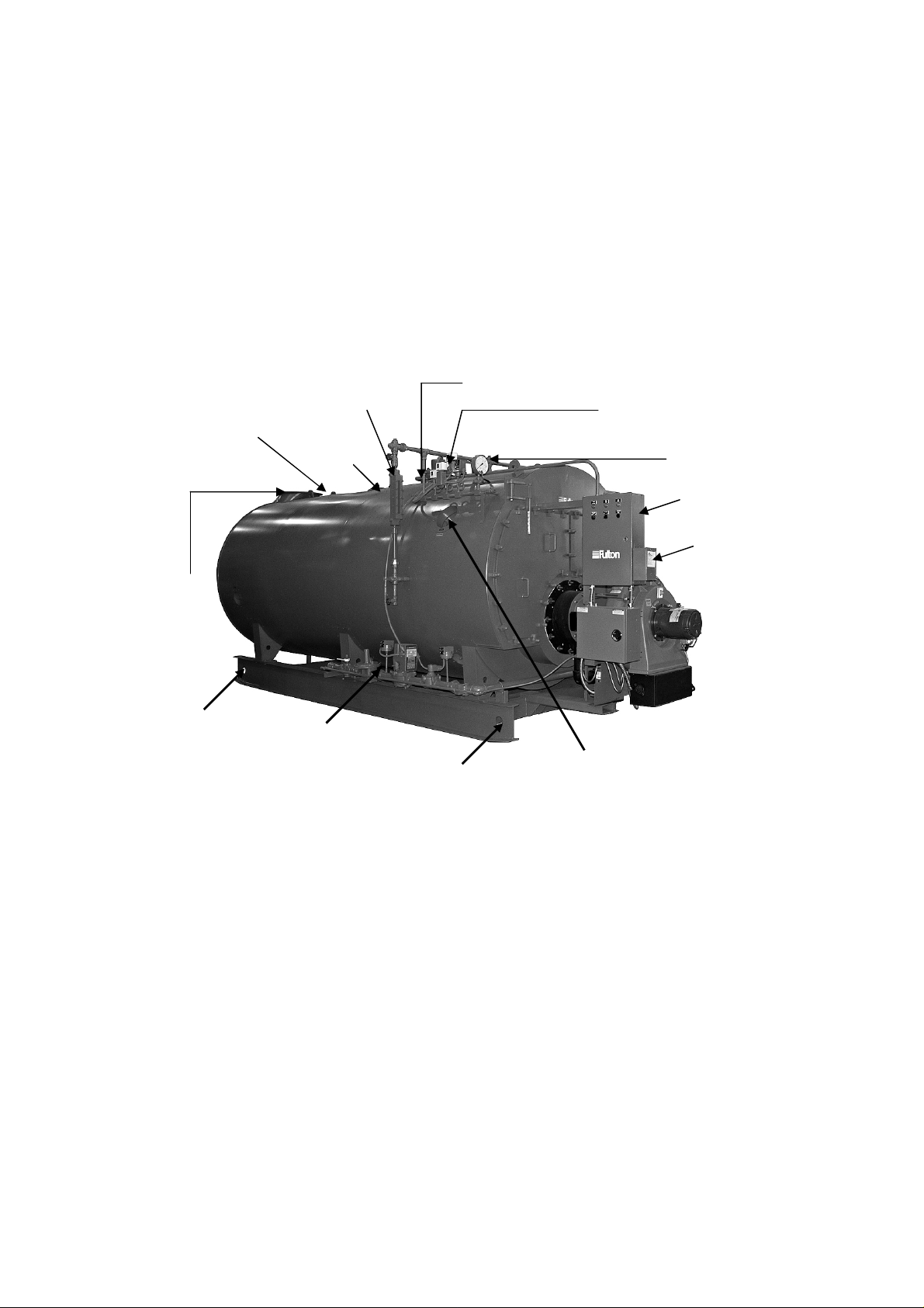
All units are crated for crane lift transport. Under no circumstances should weight be allowed to bear on
Gas Train
the jacket, control panel, or fan housing of the boiler.
The customer should examine the boiler for any damage, especially the refractories around the burner.
Rigging your boiler into position should be handled by a competent rigger experienced in handling heavy
equipment.
Safety Valve
Connection
Stack Connection
Sight Glass
Manway
Steam Outlet
Pressure Controls
Pressure Gauge
Control Panel
Burner
Rigging Point
(each side)
*Lifting eyes on top
may be used also*
Rigging Point
(each side)
*Lifting eyes on top
may be used also*
ASME Stamping
The Fulton Companies*FB-S Series Manual*Version 2010-0820 rev. 3/5/13
Page 6
Page 7

Section 1
The Fulton Companies*FB-S Series Manual*Version 2010-0820 rev. 3/5/13
Page 7
Page 8

The Fulton Companies*FB-S Series Manual*Version 2010-0820 rev. 3/5/13
Page 8
Page 9

Section 1 – Safety Warnings & Precautions
The following WARNINGS, CAUTIONS and NOTES appear in various chapters of this manual.
They are repeated on these safety summary pages as an example and for emphasis.
• WARNINGS must be observed to prevent serious injury or death to personnel.
• CAUTIONS must be observed to prevent damage or destruction of equipment or loss of
operating effectiveness.
• NOTES must be observed for essential and effective operating procedures, conditions,
and as a statement to be highlighted.
WARNING
Do not operate, service or repair this equipment unless you fully understand all applicable
sections of this manual.
Prior to commencing any internal work on any control panel or electrical junction box, the
power must be disconnected.
Do not allow others to operate, service or repair this equipment unless they fully
understand all application sections of this manual, and are qualified to operate/maintain
the equipment.
Gauge glass valves need to be fully open during boiler operation to prevent boiler water
damage in case of gauge glass failure.
Never tamper with low water cutoff sensors or circuitry.
Boiler blowdown water must be cooled to <140oF prior to discharge to a drain. Failure to
use an approved blow off vessel with adequate cooling could cause personnel/equipment
damage.
A warm boiler will have very hot metal exposed. Care should be taken not to touch these
open across without protective clothing.
The Fulton Companies*FB-S Series Manual*Version 2010-0820 rev. 3/5/13
Page 9
Page 10

CAUTIONS
A temperature exceeding 100o F in the boiler room may cause premature failure of
electrical components on the boiler control panel.
The water chemistry in the boiler must be kept within limits outlined in this manual. Failure
to do so will likely cause premature boiler pressure vessel failure and poor steam quality.
Boiler feed water temperature must be 140o F or greater to prevent corrosion fatigue
cracking at the feed water nozzle.
The bolts that connect the boiler shell to the rails need to be loosened slightly before the
boiler is warmed up to allow thermal expansion of the pressure vessel. Failure to do so
will create unwanted pressure vessel stress.
NOTES
After installation is complete and prior to operation the pressure vessel should be cleaned
or boiled out per instructions included in this manual.
The normal water level is approximately the center of the water gauge glass.
To ensure that your Fulton Steam Boiler is kept operating safely and efficiently, follow the
maintenance procedures set forth in this manual.
It is normal for the boiler safety relief valve to weep water if the boiler is operated above
90% of the valve setpoint (i.e. weep will occur for a 100 psig valve if boiler is >90 psig).
To ensure the continued safety and efficiency of the boiler, the schedule of maintenance
outlined in this section should be adhered to.
The boiler blow off operation should be done a minimum of once during the day when the
boiler is at 10 PSIG or less.
After a new Fulton Boiler has been in operation for several months, pieces of burned metal
will be found in the space at the bottom of the boiler. These pieces of metal are the
remains of a light gauge metal form which was used during manufacture for forming the
The Fulton Companies*FB-S Series Manual*Version 2010-0820 rev. 3/5/13
Page 10
Page 11

boiler insulation. This is a normal condition and does not affect the efficiency or the life of
the boiler in any way.
All secondary low water trips, flame failure trips or high steam pressure trips will require,
by code, a manual reset at the boiler.
The Fulton Companies*FB-S Series Manual*Version 2010-0820 rev. 3/5/13
Page 11
Page 12

The Fulton Companies*FB-S Series Manual*Version 2010-0820 rev. 3/5/13
Page 12
Page 13

Section 2
The Fulton Companies*FB-S Series Manual*Version 2010-0820 rev. 3/5/13
Page 13
Page 14

The Fulton Companies*FB-S Series Manual*Version 2010-0820 rev. 3/5/13
Page 14
Page 15

Section 2 – Description & Introductions
1. General
a) Fulton model FB-S is a three-pass, water back and corrugated furnace design
steam boiler. In the first pass, the flame and high temperature flue gas flows from
the front to the back of the furnace. Through the second pass pipes, high
temperature flue gas flows from the combustion furnace to the front chamber. In
the third pass, the flue gas passes through the third pass pipes to the back of the
boiler and vents out. Corrugated furnace highly increases the heat exchange
area, heat transfer efficiency and reduces the possible damage to the boiler
durability cased by heat expansion and cold contraction.
b) Boiler is designed and manufactured to comply with ASME Code, with maximum
working pressure of 1.0MPa (150 PSI).
c) The fully packaged boiler has passed the strict test before it is delivered to the
customer. The equipment will give long life and excellent service on the job if
proper operating and maintenance instructions are followed.
d) FB-S boiler is a cylindrical vessel, with horizontal tubes passing through and
connected to the front and rear tube sheets. The vessel contains the water and
absorbs the energy generated from the flame. The front door and rear door
provide the seal to contain the hot combustion gasses. Baffles designed into the
doors serve to redirect the combustion gasses through the various firetube
passages. The flame originates in the furnace. As the combustion gasses travel
down the furnace and through the various firetube channels, heat from the flame
and combustion gasses is transferred to the water. Transferred energy develops
into the required steam or hot water.
e) The front door and rear door make it easy to clean the combustion chamber. The
pressure vessel can be inspected and repaired by the manhole on the top and
handholes on the side or bottom. The general information in this manual applies
directly to boilers in sizes ranging from 1 ton/hr through 6 ton/hr steam output
boiler for the following fuels: gas, No.2-6 Oil, No2 Oil and Gas.
f) The boiler is equipped with an automatic burner for fully modulating output.
The Fulton Companies*FB-S Series Manual*Version 2010-0820 rev. 3/5/13
Page 15
Page 16
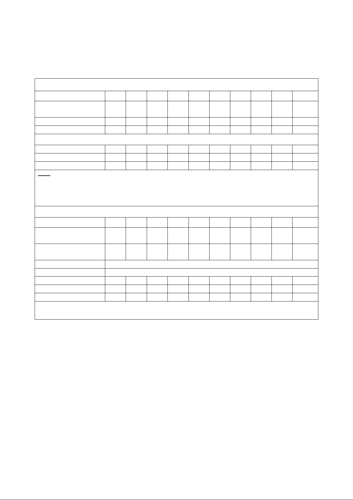
2. Specifications and Dimensions
Specifications
Model FB
-S
Maximum fuel consumption
Connection
Model FB
-S
100 125 150 200 250 300 400 500 650 800
100 125 150 200 250 300 400 500 650 800
Nominal steam output
(lbs/h) (1)
Design pressure (psig) 15/150
Water Volume (gallons) 779
Light Oil (gp/h) 29 36 43 58 73 88 117 146 189 234
Heavy Oil (gp/h) 27 34 41 54 68 82 108 136 177 216
Natural Gas (ft3/h) 4156 5196 6235 8313 10,392 12,470 16,626 20,784 27,019 33,252
Note:
(1) All steam output lbs/hr ratings from 0 psig at 212F.
(2) Fuel consumption based on light oil 1, 40,000 BTU/gal, natural gas 1000 BTU/ft3, heavy oil 160,000
BTU/gal.
3450 4312 5175 6900 8625 10350 13800 17250 22425 27600
15/150 15/150 15/150 15/150 15/150 15/150 15/150 15/150 15/150
924 924 1294 1585 1849 3594 4650 4677 5265
(2)
Main steam valve (150 psig)
Flange
Safety valve connections
(150 psig) (in)
Main steam valve (15 psig) (in) Consult Factory
Safety valve (15 psig) (in) Consult Factory
Feed Water inlet line (in) 1.0 1.25 1.25 1.25 1.25 1.5 1.5 2 2 2
Blowdown line (in) 1.5 (2) 1.5 (2) 1.5 (2) 1.5 (2) 1.5 (2) 1.5 (2) 1.5 (2) 2 (2) 2 (2) 2 (2)
Flue diameter (in) 14 16 16 18 20 20 22 22 26 26
2.5 3 3 4 4 4 6 6 6 8
2 1.5 (2) 1.5 (2) 2 (2) 2 (2) 2.5 (2) 2.5 (2) 4 4 (2) 4 (2)
Note: Specifications and dimensions are approximate. Fulton reserves the right to change specifications and
dimensions.
The Fulton Companies*FB-S Series Manual*Version 2010-0820 rev. 3/5/13
Page 16
Page 17

Section 3
The Fulton Companies*FB-S Series Manual*Version 2010-0820 rev. 3/5/13
Page 17
Page 18

The Fulton Companies*FB-S Series Manual*Version 2010-0820 rev. 3/5/13
Page 18
Page 19
Section 3 – Installation
General
Note
It is essential that the installing shall be undertaken only by suitably qualified and
experienced personnel. Installation should comply with appropriate local and state codes
and standards.
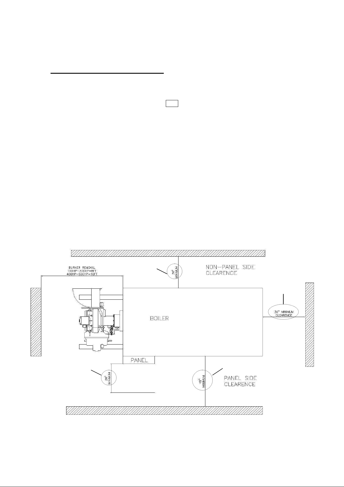
1. Locating the Boiler
a) The boiler should be closed in dry surroundings on a level base, making sure that
there is sufficient room around the boiler to enable the operator and/or the
maintenance engineer to gain access to all parts of the boiler. Check location for
ease of water supply and electrical connections.
b) Place the boiler on a non-combustible floor with clearances to unprotected
combustible materials, including plaster or combustible supports.
c) It is necessary to have enough clearance from the floor to the ceiling for
removing of the burner and have the following clearance from boiler for servicing:
36” Min
36” Min
Clearance
36” Min
48” Min
The Fulton Companies*FB-S Series Manual*Version 2010-0820 rev. 3/5/13
Page 19
Page 20

2. Boiler Room Ventilation
Model FB
-S
100 125 150 200 250 300 400 500 650 800 900
a) It is most important to provide free access of air to the boiler. To burn fuel
properly, it requires one square inch opening of fresh air for every 3, 000 BTU
input of fuel.
b) Proper ventilation of the boiler room is essential for good combustion. Install two
make up air openings, one at a low level (24” or 610mm from floor) and one at a
higher level in the boiler room wall. This will provide a flow of air to exhaust the
hot air from the boiler room.
c) The following openings are recommended for each size boiler:
Recommended Minimum Makeup Air Openings
Minimum area (in2) 1437 1797 2156 2875 3593 4312 5750 7187 9343 11,500
d) Be sure the total BHP= proper make up air opening size. For instance, if you
have three 300 BHP boilers, it is a total BHP of 900, and the 900 BHP make up
air size is recommended.
These measurements are subject to state and local regulations. The
installation of exhaust fans in a boiler room is not recommended. An
exhaust fan can create down draft in the stack or restrict the burner’s air
supply which will result in poor combustion. It is essential that only fresh
air be allowed to enter the combustion air system. Foreign substances,
such as combustible volatiles and lint, in the combustion system can
create hazardous conditions.
3. Flue and Chimney Requirements
a) The flue from the appliance and the joint between this flue and the chimney are
sealed to prevent leakage of combustion products.
b) The top of the flue or chimney shall be higher than any roof within a radius of 10
meters.
c) Checks are made to ensure that the chimney is suitable for burner and that the
proposed installation complies with the local authority and other regulations
covering such installations.
Note
The Fulton Companies*FB-S Series Manual*Version 2010-0820 rev. 3/5/13
Page 20
Page 21

d) If more than one appliance is connected to a common flue or chimney the cross-
Carbon Steel
Parameter
Feedwater
Horizontal Boiler/SteamPac Wa
ter
pH
Feedwater
Hardness as
CaCO3
Chlorides
Total Alkalinity
Total Dissolved
Suspended
Total Orga
nic
Iron
Dissolved
Visual Oil
Conductivity
section of the chimney should be adequate for the total volume of combustion
products from the appliances.
e) The total horizontal run of the boiler flue should not exceed 25% of the total
vertical rise. There should be an angle more than 15 degrees for the horizontal
run reducing the resistance of the combustion products and avoid rusting by
accumulating condensation in the flue.
f) The installer should check the draft with a meter at 0 to 0.15” W.C pressure with
the burner off. If the pressure is too low, a balancing damper may be used close
to the flue outlet to regulating the pressure of the draft.
4. Recommended Water Conditions
a) Following are recommendations for feed water and boiler water. Contact your
local water treatment professional for testing and treatment recommendations. It
is very important that a strict water treatment program be followed.
b) It is critical that the boiler pH water chemistry follow the attached schedule
whenever water is in the boiler. Solids that enter in with the feed water will
concentrate in the boiler. A regular schedule of boiler blowdown must be
maintained to prevent high solid concentrations from corroding the vessel or
forming deposits
7.5-9.5 8.5-10.5
140F* ---
Temperature
< 2ppm < 15 ppm
--- ---
--- < 500 ppm
--- < 3000 ppm
Solids
No visual turbidity** No visual turbidity**
Solids
No sheen No foam + No sheen No foam +
Carbon
Colorless liquid++ Colorless liquid++
<1 ppm* ND
Oxygen
ND ND
--- < 4477
(µµµµS/cm)
NOTES:
*Feedwater temperatures below 200oF will require an oxygen scavenger
** Suspended solids: Take a water sample. After the sample sits for 10 minutes, no solids should be visible.
The Fulton Companies*FB-S Series Manual*Version 2010-0820 rev. 3/5/13
Page 21
Page 22

+ Total Organic Carbon: Take a water sample. Shake vigorously for 30 seconds. No sheen or foam should be visible.
++ Iron: Take a water sample. Hold the sample against a white background. The water should have no visible yellow, red
or orange tinge.
ND: None Detected.
5. Water Supply
a) The quality of the water used in the boiler will affect the life of the elements and
pressure vessel and it is strongly recommended that a competent water
treatment company be consulted prior to the installation of the boiler. PV
damaged due to adverse water conditions will not be replaced under warranty.
b) Natural feedwater supplies contain solids and dissolved gases. These may
promote scale, foaming, corrosion, and/or poor steam quality. To prevent this,
feedwater must be studied individually and treated accordingly. The treatment
should provide quality feedwater to the boiler such that corrosion and deposition
in the boiler will be minimized. Thermal cycling, dissolved oxygen, high or low pH
can all be major causes of corrosion. Untreated hardness is the major cause of
scale deposits. Poor quality feedwater requires increased blowdown and
increased chemical treatment costs to prevent boiler corrosion and scaling.
c) One way to lower the amount of dissolved gases in the boiler feed water is to
preheat the feedwater. This option injects live steam into the feedwater to
increase the water temperature to 180 degrees F or higher which removes
oxygen and carbon dioxide from the water.
d) RO/DIWater: Reverse Osmosis / Deionized water is water that all dissolved
solids have been removed. Very high purity steam quality can be obtained with
RO/DI water. RO/DI water has no buffering capacity and a pH of <6.5. It is
corrosive to carbon steel, however, not to stainless steel. Therefore, anytime
RO/DI water is used in a carbon steel vessel, pH neutralization is required to
bring the pH up to the required level.
e) The Fulton Warranty does not cover damage or failure that can be attributed to
corrosion, scale or fouling.
6. Glossary of Water Supply Terms
a) Dissolved Oxygen: Oxygen that is dissolved in the feedwater will cause the
steel in the boiler and the feedwater system to be attacked by the water in a
manner described as “pitting”. The pits that are produced can vary from tiny
depressions to holes large enough to penetrate the boiler metal and are usually
covered with tubercles of iron oxide. Once pitting starts, it may be extremely
hard to arrest. Pitting can proceed at a surprisingly rapid rate and can occur not
The Fulton Companies*FB-S Series Manual*Version 2010-0820 rev. 3/5/13
Page 22
Page 23

only in the boiler proper, but also in pre-boiler equipment such as ecomomizers,
feedwater tanks, and feedwater lines.
b) Sodium Sulfite: Its purpose is to chemically remove the dissolved oxygen left in
the feedwater after the feedwater has been mechanically deareated. Sodium
Sulfite reacts chemically with dissolved oxygen, producing sodium sulfate. Since
it is desirable to remove dissolved oxygen from the feedwater before it reaches a
boiler. Sodium sulfite is best introduced continuously at some suitable point in the
feedwater system (the storage section of the feedwater heater or deareator, six
inches below the water line). Chemical residual control is based on the
maintenance of a specific excess of sodium sulfite in the boiler water. The
essential requirement being to maintain in the feedwater at all times slightly more
than enough sodium sulfite to consume all of the dissolved oxygen that slips
through the deareating equipment. Sulfite as a treatment represents the second
line of defense against oxygen corrosion. Primary protection against this type of
attack requires adequate facilities for mechanical deareation of the feed-water
plus a vigorous maintenance program to safe guard against oxygen leakage into
the pre-boiler system.
c) Suspended Solids: Suspended solids are the undissolved matter in water, inc-
luding dirt, silt, vegetation, iron oxides, and any other insoluble matter. Normally
suspended solids are expressed in terms of turbidity. Suspended solids may also
deposit in low velocity areas and create fouling. In line filters, or various types of
pretreatment can be used to lower the suspended solids level. Various polymers
assist in holding solids in suspension. Periodic blowdowns will eliminate
suspended solids.
d) Alkalinity: Alkalinity is the capacity of a water to neutralize acids. Common water
alkalinities consist of bicarbonate, carbonates, hydroxide, phosphate, and
silicate. These alkalinities, especially bicarbonates and carbonates, break down
to form carbon dioxide in steam, which is a major factor in the corrosion on
condensate lines. High alkalinity also causes foaming and carry over in boilers.
Both foaming and carry over cause erratic boiler operation. When foaming occurs
an antifoam should be added or increased. The reason for the high alkalinity
should be determined. It may result from lack of sufficient blow off. Quite often
the source of alkalinity is an overdose of alkaline internal water treatment
chemical.
e) pH: pH is a measure of the degree of acid or base of solution. pH ranges of 8.0-
10.5 will have little influence on the corrosion rate of carbon steel. A low pH can
result in corrosion of metals, while a high pH can result in scale formation or
The Fulton Companies*FB-S Series Manual*Version 2010-0820 rev. 3/5/13
Page 23
Page 24

caustic embrittlement. In order to control boilers and equipment used for the
external treatment of make up water, it is essential that reliable pH
measurements be made. RO/DI water will have a pH of 6.0 - 6.5 and will require
neutralization if used in a carbon steel vessel.
f) Chlorides: If chloride levels are high enough to cause severe corrosion, they can
be controlled by limiting the cycles of concentration and increasing boiler
blowdowns. Corrosion from chlorides can also be controlled by increasing the
amount of corrosion inhibitor or changing to a more effective inhibitor. Reverse
osmosis is another method of pretreatment to reduce chlorides. Chlorides are a
major concern in a stainless steel vessel.
g) Oil: Oil is not a natural constituent of boiler water; still it can frequently enter a
system through leaks in a condenser or other heat exchanger. Oil can also enter
a system through the lubrication of steam driven reciprocating equipment.
Whatever the source, the presence of oil in boiler water is undesirable. Oil can
act as a binder to form scale. In high heat-transfer areas oil can carbonize and
further contribute to the formation of scale and low pH. Foaming is one indication
of oil in boiler water. Its presence can also be confirmed by first shaking a bottle
containing boiler water. If oil is present foam will result. Often oil in boiler water
will originate in the condensate. This contaminated condensate should be
directed to the sewer until the source of the oil is determined and corrective steps
taken.
h) Iron (oxides): Iron in any of its oxide or complex forms is undesirable in boiler
water. Iron in its various forms can originate in the raw water makeup,
condensate return water, or form directly in the boiler as a result of corrosion. It
can concentrate in the boiler and it tends to collect in stagnant areas. If a boiler
is using raw water makeup, iron is almost certain to be a major component of
developing scale or create fouling.
i) Water Hardness: Water hardness is the measure of calcium and magnesium
content as calcium carbonate equivalents. Water hardness is a primary source
of scale in boiler equipment. Hardness is removed by softening.
j) Feedwater: Feedwater is the combination of fresh makeup and returning
condensate that is pumped to the boiler.
k) Condensate: Condensate is condensed steam that is normally low in dissolved
solids. Hence, it does not contribute to the dissolved solid content of the
feedwater. In addition, condensate is very expensive to waste. It's been
chemically treated, heated, pumped, converted to steam, and condensed. This
costs money and when condensate is returned to the boiler, money is saved.
The Fulton Companies*FB-S Series Manual*Version 2010-0820 rev. 3/5/13
Page 24
Page 25

7. Valves
a) Pressure Gauge: the pressure gauge is above the panel box, which is installed
on the right hand of the boiler. A three-way valve is fitted with the pressure
gauge, to assist drain off regularly.
b) Main Steam Valve: the main steam valve is installed on the top of the boiler. It
will be connected with the steam pipe work to all kinds of equipment, which
consume steam. There should be enough outlet for drain off and flush in the pipe
work.
c) Safety Valve: the safety valve is installed on the top of the boiler. Its setting was
finished by the manufacturer before delivery; do not attempt to change the
setting. The function of the safety valve is to avoid pressure in the boiler from
exceeding the design valve. Any equipment connected with the boiler can run
under the boiler pressure. If not, another safety valve must be used to protect it.
CAUTION
The safety valve supplied by the manufacturer can only protect the boiler;
it cannot protect any other equipment in the system.
d) Water Level Gauge: the water level gauge is equipped to monitor the boiler water
level. The boiler operator can see the water level inside the boiler from these
gauges. Both of them are connected to a drain line for periodic flushing.
8. Electrical Requirements
a) Connect wiring as shown in the wiring diagram, which is furnished
inside the electrical control panel box.
b) Electrical power available is usually 230/460 volt, 3 phase, 60 HZ (in
USA), 3 phases, 50 HZ (outside USA).
9. Gas Supply
a) Natural gas is the standard gas for the gas boiler. Special
requirements on request- i.e. liquid petroleum gas, town gas.
b) Gas must be supplied at a pressure high enough to overcome the
pressure loss in the burner gas train and furnace while running at full
input. This pressure is different based on the burner used. The
pressure must be checked to make sure it is high enough. If it is too
low, a gas booster must be used in the gas supply system.
The Fulton Companies*FB-S Series Manual*Version 2010-0820 rev. 3/5/13
Page 25
Page 26

c)
Pipe
Length of Pipe in Feet
Inches
10 20 30 40 50 60 70 80 90
100
½
¾
1
1 ¼
1 ½
2
2 ½
3
The gas supply piping to the boiler must be appropriate to local
conditions and must be
constructed and installed in compliance
with appropriate Codes and Standards. It should be of sufficient size
to satisfy the pressure and volume flow requirements of the burner
under all firing
conditions. Checks should be made to ensure that all
meters and other components are appropriately rated for the maximum
gas flow rate anticipated.
Note
It is essential that a manual isolation valve is fitted upstream of the gas
control train to allow the burner to be isolated for maintenance. The size of
this valve should not be less than that of the burner control train in order to
avoid any restriction in gas flow.
Warning
It is essential that the installation of the gas piping must be undertaken
only by suitably
with appropriate Codes and
qualified and experienced personnel and in compliance
Standards. The Fulton Companies can accept
no responsibility for consequential loss, damage or personal injury, which
results from a failure to follow the manual.
Gas Line Sizing Chart
*There is a more exact formula, but you can round off the conversion of CF to BTU by using 1=1000 (for
example 174 CF on the chart would be equal to 174,000 BTU). This will give a more conservative total
estimate.
Size
174 119 96 82 73 66 61 56 53 50
363 249 200 171 152 135 127 118 111 104
684 470 377 323 286 259 239 222 206 197
1404 955 775 663 588 532 490 456 428 404
2103 1445 1161 993 880 795 734 688 641 605
4050 2784 2235 1913 1696 1538 1413 1315 1234 1165
6455 4437 3503 3049 2703 2449 2253 2096 1966 1857
11,412 7843 6299 5391 4778 4329 3983 3705 3476 3284
The Fulton Companies*FB-S Series Manual*Version 2010-0820 rev. 3/5/13
Page 26
Page 27

10. Oil Supply
Example: From the chart we can see that a ¾” line that is 80’ in length can supply
118,000 BTU/hr.
a) The oil supply piping to the boiler must be appropriate to local conditions
and must be constructed and installed in compliance with appropriate
Codes and Standards. It should be of sufficient size to satisfy the
pressure and volume flow requirements of the burner under all firing
conditions. Checks
other components are appropriately rated for the
rate anticipated. Galvanized steel pipe should not be used. The supply
piping should include an appropriate filter.
b) A two-pipe system must be used between oil storage tank and the
burner. One for oil supply and one for oil return. A circulating oil pump is
required to deliver fuel oil at 1-3 psig from the storage tank to the
A oil filter must be installed before the oil-circulating pump,
recommend less than 60
c) The final connection to the oil pump inlet should be made using the
flexible pipes supplied with the burner.
d)
One gate valve should be installed to the inlet and outlet of the
circulating pump separately. A
added to the outlet.
e) It is important to ensure that the return pipe is not obstructed as this
may result in damage to the pump.
f) In the case of heavy oil (No.4, No.5, and No.6 oil) the piping and oil
storage tank should be insulated, trace heated and thermostatically
controlled.
should be made to ensure that all meters and
maximum oil flow
Mesh.
pressure gauge (0-60psi) should be
burner.
11. Installation Check Points-Refer to the details in the BURNER section
a) Make sure that all piping connections are complete and tight.
b) Make sure the pressure controls are adjusted properly.
c) Make sure all electrical connections in the control box, the water column,
and elsewhere are secure.
d) Make sure there is adequate boiler room ventilation. Combustion air
contaminates can cause damage to the boiler jacket and burner.
e) Before operating pumps, metering heads and compressors, make
certain that reservoirs are properly
The Fulton Companies*FB-S Series Manual*Version 2010-0820 rev. 3/5/13
Page 27
filled with the specific lubricant.
Page 28

12. Cleaning
Open all necessary oil shut-off valves. Do not run compressors,
pumps, or metering units without oil.
f) Before connecting electrical current to any component, be sure the
supply voltage is the same as that specified on the component
nameplates.
g) Make certain that the operator in charge is properly instructed in the
operation and maintenance procedures.
Note
The pressure vessel must be cleaned before running the boiler after
installation.
Steam Piping
a) Steam and water piping systems connected to the boiler may contain
oil, grease, or foreign matter. The impurities must be removed in order
to prevent damage to pressure vessel heating surfaces. On a steam
system, the condensate should be wasted until tests show the
elimination of undesirable impurities. During the period that
condensate is wasted, attention must be given to the treatment of the
raw water used as make-up so that an accumulation of unwanted
materials or corrosion does not occur. For more information, contact
your local authorized boiler representative.
Pressure Vessel
a) The waterside of the pressure vessel must be kept clean from grease, sludge, and
foreign material.
vessel, will interfere with efficient
Such deposits, if present, will shorten the life of the pressure
operation and functioning of control, of safety
devices, and possibly cause unnecessary and expensive re-work, repairs, and
down-time.
b) The installation and operating conditions that the boiler will be subjected
to should be considered, and
pressure vessel should be provided during the course of initial
cleaning of the waterside of the
start-
up.
c) The pressure vessel and the steam and return lines, in effect, represent
a closed system. Although the steam and return (condensate) lines
system may have been previously cleaned, it is possible that:
The Fulton Companies*FB-S Series Manual*Version 2010-0820 rev. 3/5/13
Page 28
Page 29

1. Cleaning has been inadequate.
2. Partial or total old system is involved.
3. Conditions may prevent adequate clearing of piping.
d) The pressure vessel waterside should be inspected on a periodic basis.
An inspection will reveal
internal conditions and serve as a check
against conditions indicated by chemical analysis of the boiler water.
Inspection should be made three months after initial starting and at
regular 6-, 9-, or 12-month intervals thereafter. The frequency of
further periodic inspections will depend upon the internal conditions
found.
e)
If any unwanted conditions are observed, contact your local
authorized boiler representative for
recommendations.
f) Any sludge, mud or sediment found will need to be flushed out. If
excessive mud or sludge is noticed during the blowdown the scheduling
or frequency of blowdown may need to be revised. The need for periodic
draining or washout will also be indicated.
g) Any oil or grease present on the heating surfaces should be removed
promptly by a boil-out with an alkaline detergent solution.
Temperatures of initial fill of water for hydrostatic tests, Boil-out, or for
normal operation
Do not store halogenated hydrocarbons in or near the boiler room. In general,
ensure that the boiler area is in conformance with established boiler room
requirements. Review national and local codes.
h) As a final checkpoint, again...Water Treatment! We cannot emphasize enough the
importance of proper water treatment: Water analysis should be made by a
competent water treatment professional and their recommendations should be
followed.
13. Boil-out of New Unit
a) The internal surfaces of a newly installed boiler may have oil, grease or other
protective coatings
Note
should be as stated in the ASME Boiler Code.
Caution
used in manufacturing. Such coatings must be removed
The Fulton Companies*FB-S Series Manual*Version 2010-0820 rev. 3/5/13
Page 29
Page 30

because they lower the heat transfer rate and could cause over-heating of a tube.
Before boiling out procedures may begin, the burner should be ready for firing. The
operator must be familiar with the procedure outlined under burner operation.
Warning
Use of a suitable facemask, goggles, rubber gloves, and protective
garments is strongly
chemicals. Do not permit the dry material or
come in contact with skin or clothing. Failure to follow these
recommended when handing or mixing caustic
the concentrated solution to
instructions
could result in serious personal injury or death.
b)
The suggested general procedure for clearing a boiler is as follows:
i. Have sufficient cleaning material on hand to complete the job.
ii. When dissolving chemicals, the following procedure is suggested.
Warm water should be put into a suitable container. Slowly
introduce the dry chemical into the water, stirring it at all times
until the chemical is completely dissolved. Add the chemical slowly
and in small amounts to prevent excessive heat and turbulence.
iii. Isolate the boiler from the system by shutting off the main steam
valve.
iv. Remove the steam safety valve.
v. Water relief valves and steam safety valves must be removed
before adding the boil-out solution so that neither it nor the grease
which it may carry will contaminate the valves. Use care in
removing and reinstalling the valves.
vi.
All valves in the piping leading to or from the system must be
closed to prevent the cleaning
solution from getting into the
system
vii. Replace the steam safety valve.
viii. Fill the boiler with water. Water level is about center in the water
gauge glass.
ix. Generate 5 PSI (1.054 kg/cm2) of steam and shut off the boiler.
Allow this hot solution to remain in the boiler for 10 minutes.
x. Allow the boiler to cool to <140F.
xi. Drain and flush the boiler twice with fresh water.
xii. To remove all the oil and dirt from the main steam and the
condensate return lines, allow the returns to go into a floor drain or
a safe discharge point for the first few days of operation.
The Fulton Companies*FB-S Series Manual*Version 2010-0820 rev. 3/5/13
Page 30
Page 31

Warning
Be sure to drain the hot water to a safe point of discharge to avoid scalding.
Failure to follow these instructions could result in serious personal injury or
death.
xiii. Remove hand-hole plates.
xiv. Inspect the surfaces. If they are not clean, repeat the boil out.
xv. After closing the hand-holes and reinstalling the safety or relief
valves, fill the boiler and fire it until the water is heated to at least
180oF to drive off any dissolved gases, which might otherwise
corrode the material.
xvi. The above procedure may be omitted in the case of a unit
previously used or known to be internally clean. However,
consideration must be given to the possibility of contaminating
materials entering the boiler from the system.
xvii. On a steam system, the condensate should be wasted until tests
show the elimination of undesirable impurities. During the period
that condensate is wasted, be sure make-up water is treated to
prevent an accumulation of unwanted materials or corrosion.
The Fulton Companies*FB-S Series Manual*Version 2010-0820 rev. 3/5/13
Page 31
Page 32

The Fulton Companies*FB-S Series Manual*Version 2010-0820 rev. 3/5/13
Page 32
Page 33

Section 4
The Fulton Companies*FB-S Series Manual*Version 2010-0820 rev. 3/5/13
Page 33
Page 34

The Fulton Companies*FB-S Series Manual*Version 2010-0820 rev. 3/5/13
Page 34
Page 35

Section 4 – Controls & Burner
The following brief description of the fittings and controls used on the FB-S boiler is intended
to
provide the operator with a basic understanding of the operating principles, which is essential for
the continued efficient use of the boiler.
1. Boiler Control Panel
a)
Boiler controls and indicators are housed in a control panel mounted on the
side of the boiler.
i. Power Isolator Switch- control panel power supply ON/OFF switch,
mounted on the panel door.
ii. Power On Indicator- indicates that the door isolator is in the ON position
and the panel is electrically live.
Various Relays
These controls are as follows:
Flame Programmer
The power on the indicator is derived from one phase. It is possible for
that the Power On Indicator supply phase to be down, leaving the other
two phases live. Always isolate the
Motor Fuses
Fan Motor Starter
Water Level Relays
Warning
supply before working on the panel.
The Fulton Companies*FB-S Series Manual*Version 2010-0820 rev. 3/5/13
Page 35
Page 36

b)
Low Water Indicator
i. This lamp will be illuminated and an alarm sounded when the water level,
as sensed by an internal probe, in the boiler falls to the 1
st
low water
level. The burner will shut down and the alarm will continue to sound until
the water level is restored to a safe working level. The alarm will then
cancel, the indicator lamp will extinguish and the burner will automatically
restart.
c) Low Water Alarm/Reset Switch
i. Sounds and alarm on switch on, press to reset. If the level of water in the
boiler falls below the second pre-set limit, as sensed by a second low
water internal probe, during boiler operation. The 2nd Low Water
Alarm/Reset Switch will illuminate, the alarm will sound and the burner
will shut down. The water level must be restored before the alarm can be
cancelled by pressing the switch.
d) High Water Indicator
i. This lamp will illuminate and alarm sound when the water level reaches a
pre-determined high level, as sensed by an internal probe. The feed pump
will stop. When the water level falls to the normal working level, the
indicator lamp will extinguish and the alarm cancel.
Note
The Burner ON/OFF/Reset switch should be in the OFF
position during the filling process.
The Pump Hand/Off/Auto Switch should be in the PUMP Auto position,
except when manually filling the boiler (Hand position).
The 2nd Low Water Alarm can only be cancelled if the boiler water level is
above the 2
nd
Low Water Level. If the alarm cannot be cancelled, allow the
feed water pump to restore the water level to the normal working level
(approximately mid-way up the sight glass) and the reset the alarm.
e)
Low Water Safety Relays and Feedwater Pump Relays
i.
These relays operate in conjunction with probes suspended in the
boiler shell (or externally mounted floater pressure differential
transmitters) to automatically
between set limits. If the water should fall to an unsafe level, the
maintain the water level in the boiler
burner is
cut out and an alarm is sounded. The probes are located in two,
The Fulton Companies*FB-S Series Manual*Version 2010-0820 rev. 3/5/13
Page 36
Page 37

100mm diameter
2nd
LWCO
Pump On
1st
LWCO
Pump Off
High Water
standpipes mounted on top of the boiler center line
towards the front of the boiler. A standard boiler is fitted with Feedwater
pump On/Off, 1st Low Water, 2nd Low Water and High Water probes.
Note
If the Level Control System is a float type or pressure differential transmitter,
then refer to specific spec sheets located in this manual.
f) Steam Pressure Controls
i. Three steam pressure controls are mounted on the side of the boiler near
the control panel. These are as follows:
a. Operating Control Pressure On/Off Switch. Controls the
on/off cycle of the boiler, switching the burner off when
the desired steam pressure is reached and switching it
on when steam pressure falls.
b. High Limit Switch. Should the Control Pressure Switch
fail, the steam pressure will raise above
the pre-set limit causing the High Limit Switch (set a
least 0.5 {3-4 psig} bar higher than the Control
Pressure Switch) to switch off and lock out the burner. A
High Limit Indicator will illuminate and an alarm will sound.
c. Modulating Pressure Switch. Switches the burner from high
to low flame and vice-versa as steam pressure/water temp
increases or decreases from setpoint.
The Fulton Companies*FB-S Series Manual*Version 2010-0820 rev. 3/5/13
Page 37
Page 38

High Limit w/
Manual Reset
Operating Limit
Modulating Control
Note
Boiler may be supplied with PID type pressure controls in lieu of on/off and
high/low pressure switches.
g) Burner Programmer
i. Is located in the center of the control panel. Acts in conjunction with a
sensing device to ‘supervise’
the ignition sequence, prove the flame is
satisfactory and finally ‘monitor’ the established flame.
Should any fault occur, either during the ignition sequence or during
normal running, the programmer will immediately go to ‘lock-out’ and both
main and pilot gas/oil valves will shut to isolate the fuel line
to the burner. Lockouts include high steam pressure, low water, high/low
gas pressure and flame failure.
h) Flame Failure Indicator
i.
Indicates the burner combustion control relay, detects a flame failure
condition.
2. Burner
Fulton Boiler FB-S model can mount with gas burner, oil burner or dual fuel burner
on customer’s request. See specific Burner Manual fro details.
Oil Burner
The fuel for the oil burner is from No.2 to No. 6 oil.
a Fulton boiler is No.2 oil. The heavy oil burner
The standard light oil burner for
can be used for No.4 to No.6
oil.
The Fulton Companies*FB-S Series Manual*Version 2010-0820 rev. 3/5/13
Page 38
Page 39

Possible Burner Options for FBS
a) Air Pressure Switch
i.
Mounted on the burner, this switch is
entering the burner though the
or insufficient air
pressure, will stop the switch completing the circuit,
throat of the scroll. Lack of combustion air,
preventing the burner from operating.
operated by the pressure of air
b) Air Damper Servomotor
i. The combustion air control system
servomotor. The servomotor is
including air damper and a
mounted on the burner and directly
coupled to the air damper blade. this system monitors and controls the
combustion air entering the burner on the requirement of the boiler heating
during operating. A fully closed position is provided to prevent air flowing
through the appliance when the burner is not in operation.
c) The Inner Assembly
i. Consist of flame tube, diffuse, oil nozzle, ignition electrode and so on.
d) Oil Nozzle
i. The oil nozzles are held in a nozzle block located within the flame
tube. The nozzles
heat inputs required and the available
are pre-sized by the manufacture according with the
operating pressure. When
replacing the nozzles, they must be the same capacity as the original.
Note
When fitting nozzles to the heavy oil burners the nozzle filters must be
removed.
In calculating the correct size of nozzles to be fitted, refer to the specific
burner manual.
The Fulton Companies*FB-S Series Manual*Version 2010-0820 rev. 3/5/13
Page 39
Page 40

e) Oil Pre-heater Tank (for heavy oil burners)
i. The oil preheater tank is mounted on the heavy oil burner ahead of the fan
housing. Its function is to preheat the oil to correct temperature. The unit is
equipped with three thermostats, ‘low temperature’ ‘operating’ and
thermometer and hot oil filter are mounted together as
top left-hand side of the preheater tank viewed
from the rear of the
one unit on the
‘limit’. A
burner.
f) Air Pressure Switch
i. Each of the gas burners is mounted on an Air Pressure Switch on the
burner scroll. Lack of combustion air, or insufficient air pressure, will stop
the switch completing the circuit, preventing the burner from operating.
g) Air Control
i. The Air Control System of the gas burners is similar to that of the oil
burners. The servomotor is mounted on
burner and directly
coupled to the air damper blade. This system
the rear of the air inlet of the
monitors and controls the combustion air entering the burner on
the requirement of the boiler heating during operating. The servomotor has
been adjusted by the manufacturer before the boiler delivery, so normally
the customer needn’t set it again.
h) Gas Train Assembly
i. Consist of pilot and main supply line, each line having a manual cock, a
governor, solenoid operated valves and two-air pressure switch (high and
low). The governors maintain a constant pressure of fuel entering the
burner and are adjustable. The solenoid valves are electronically controlled
by the burner programmer. For specific details, consult the burner
manufacturer’s instruction manual.
The Fulton Companies*FB-S Series Manual*Version 2010-0820 rev. 3/5/13
Page 40
Page 41

i) Valve Proving System
i. A valve proving system, as show schematically below, is standard on the
FB-S Boilers.
control box energizes the proving system, which then carries out the
following checks.
j) Flame Monitor
i. An ultraviolet cell is fitted as standard on all burners. It monitors the status
of the flame, any failure will cause the burner to shut down.
When the boiler operating sequence is initiated, the burner
a. Valves V1, V2 and V3 are initially closed. The proving
system then opens V3 and then closes it after 2 seconds.
b.
V1, V2 and V3 remain closed for 23 seconds while the
minimum side of the gas pressure
for an increase in pressure. If no crease occurs there is
no leakage past V1 and the sequence continues.
c.
V1 is opened for 2 seconds and then closed. V1, V2
and V3 again remain closed for 23 seconds while the
maximum side of the gas pressure switch checks for
a decrease in
no leakage past V2 or V3 and the burner operating
sequence will continue.
pressure. If no decrease occurs there is
switch (PS) checks
The Fulton Companies*FB-S Series Manual*Version 2010-0820 rev. 3/5/13
Page 41
Page 42

The Fulton Companies*FB-S Series Manual*Version 2010-0820 rev. 3/5/13
Page 42
Page 43

Section 5
The Fulton Companies*FB-S Series Manual*Version 2010-0820 rev. 3/5/13
Page 43
Page 44

The Fulton Companies*FB-S Series Manual*Version 2010-0820 rev. 3/5/13
Page 44
Page 45

Section 5 – Operation
Boiler starting
STOP! Make sure you have read any followed all previous safety information.
Check with local authorities where approval for start-up is required. In some
localities, final inspection of services may be required.
In general, ensure that the boiler area is in conformance with established boiler
room requirement. Review national and local codes.
Carry out the following procedure on the initial start up of the boiler and on every
subsequent occasion when restarting the boiler after a shut down.
1. Filling the Boiler
a) Ensure the following valves are OPEN
i. Main Steam Valve
ii. Steam pressure gauge isolating valve
iii. All valves in the water feed line
iv. Water gauge isolating valves
v. Air release valves
b) Ensure the following valves are SHUT
i. Surface and bottom blowdown valves
ii. Water gauge blowdown valves
iii. All valves in the gas/oil train to the burner
c) Ensure that the Burner On/Off/Reset Switch is set to OFF
d) Ensure that the Pump On/Off switch is in the PUMP OFF position, and that the
Hand/Off/Auto Switch is in the Off position.
e) Place the Pump On/Off Switch to the PUMP ON position, or Hand/Off/Auto in the
Auto position.
f) The feed pump should start and fill the boiler to the pump off level and then switch
off.
The Fulton Companies*FB-S Series Manual*Version 2010-0820 rev. 3/5/13
Page 45
Page 46

If the 2nd Low Water and High Pressure Alarm/Reset switch illuminate and
the alarms sound, check that the burner mounted Burner On/Off/Reset
Switch is in the OFF position, and then reset both alarms by pressing the
switches
It may be necessary to vent the feed water pump by bleeding air from the
plug mounted in the top casting below the pump motor to pump body
connection
2. Starting the Burner From Cold
a) Fill the boiler as described in Section 1.
b) SHUT the main steam valve.
c) Open all the valves in the gas train/oil supply. It is assured that the fuel supply
lines have been purged prior to attempting to start the boiler/burner.
Note
Note
d) Switch the Burner On/Off/Reset Switch to the ON position. The 2nd Low Water and
High Pressure Alarm/Reset switches will illuminate and alarms will sound due to
the power restoration interlock.
e) Reset the alarm by pressing both switches. If the 2nd Low Water alarm cannot be
cancelled, check the water level in the sight glass.
f) The burner motor will start and, after going through post purge/ pre purge interlock
checks, should fire after approximately 45 seconds.
Note
Before leaving the boiler unattended, the daily operating tests should be
carried out to check the functions of all the safety interlocks. For more
detailed information on the burner firing sequence consult the burner
manufacture’s Operation and Maintenance instructions.
Practical Considerations
When starting up the boiler, it is prudent to minimize the thermal and mechanical stress
caused by differential expansion of various parts of the boiler as they reach working
temperature. The temperature of the shell is determined by the contained water/steam
The Fulton Companies*FB-S Series Manual*Version 2010-0820 rev. 3/5/13
Page 46
Page 47

temperature and by the heat transfer rate and gas temperature. The tube temperature lies
between the shell and furnace temperature, but is nearer the shell temperature. Since all
these components are virtually the same length, they expend longitudinally by different
amounts causing mechanical and thermal stress. Whilst this is catered for in mechanical
design of the pressure vessel, the life expectancy of the boiler can be affected if the boiler
is frequently heated to quickly from cold. When starting from cold the furnace approaches
its design temperature shortly after start-up, whereas the tube and shell temperatures are
delayed by the time taken to bring the contained water up to temperature. As a result, the
thermal expansion is at its greatest. Additionally, the temperature gradient which exists
between the bottom and the top of the boiler is exaggerated. This can be
reduced by blowing the boiler down during the heat-up period. In practical terms, the ideal
solution would be to gradually raise the temperature and pressure in the boiler
progressively by firing the boiler on low fire for a few minutes and leaving it to ‘soak’ (e.g.
allowing the temperatures in the boiler and water to even out by diffusion) for 20 to 30
minutes, blowing down the boiler, firing the boiler again for a little longer and soaking for
less, and so on. If the boiler has been fired the day before, the large thermal mass in the
boiler will maintain the internal temperature to a point that the boiler can be simple switched
on (preferably on low fire) and then left to reach working temperature/pressure. The life
expectancy of the boiler and door insulation, ignoring other factors, is proportional to the
number of the thermal/mechanical cycles that the boiler undergoes from cold/zero pressure
to working temperature and pressure. A boiler that is continually maintained at working
pressure will last longer than one that is constantly heated and cooled.
Service Inspection of Weld Joints
The frequency of the safety requirement for in service inspection of the main welded joints
of the boiler is calculated by the number of cycles since the last inspection. Boilers running
twenty four hours a day require the shell and furnace end plate welds to be inspected at
intervals specified by local boiler codes. Boilers that are continually heated and cooled
require more frequent inspection. The purpose of the in-service weld inspections is to check
for:
i. Buried defects during manufacture that are outside acceptable limits.
Because the boiler was 100% tested during manufacture none should be
found, and upon proof of 100% manufacturer testing these tests may be
waived at the discretion of the ‘competent person’.
ii. Cracks propagating from region of the toe of the fillet weld on the shell to
the tube plate weld, resulting from fatigue or corrosion fatigue cracking.
The Fulton Companies*FB-S Series Manual*Version 2010-0820 rev. 3/5/13
Page 47
Page 48

These cracks would not be there after manufacture but can develop in
service, they are caused by stress due to a combination of pressure loads,
differential expansion, local temperature gradients, oxygen impurities in the
boiler water/steam and inadequate PH (water chemistry) control.
Differential thermal expansion and local temperature gradients all result
from continuous pressure/temperature cycling and heating from cold too
quickly. Water treatment and in particular
oxygen corrosion are covered in Section 3. The importance of correct
water treatment cannot be over emphasized.
To Achieve Long Trouble-Free Boiler Life:
i. Maintain the boiler at working pressure as long as possible, minimize
cycling.
ii. When heating from cold do so slowly.
iii. Maintain water treatment within the prescribed limits at all times, blowdown
frequently.
3. Daily Operating Tests
Caution
If any of the following tests fail to function as described, shut down the boiler
immediately and consult the factory.
With the burner firing, carry out the following tests:
Note
Ensure the correct water level is maintained during pressure build up. If
any part of the
equipment is not operating correctly, the fault should be
investigated before the boiler is used. Ensure all blowdown piping is safe and
discharged to a blowdown receptacle.
a) Flame Sensor (UV Photo Cell) Check
i. Remove the burner UV photocell from its plug-in connection (on the side of
the burner) and cover the
burner control should immediately (2-3 seconds gas, 5
detection window to exclude all light. The
seconds oil) go
to a lockout/flame failure condition and will require manual resetting.
Clean the UV photocell with soft cloth before replacing it.
The Fulton Companies*FB-S Series Manual*Version 2010-0820 rev. 3/5/13
Page 48
Page 49

b) Pump Check
i. Lower the water level in the boiler, either by evaporation or by opening
the main blowdown valve with the key provided.
ii.
Observe the water level in the water level gauges and, as the water
level falls, check that the
iii. SHUT the main blowdown valve if opened, and ensure that the feed
water pump continues to fill the boiler to the correct level then switch
off.
c) 1st Low Water Check
i. Turn the Pump On/Off Switch on the boiler control panel to the PUMP
OFF position.
ii. Lower the water level in the boiler, either by evaporation or by opening
the main blowdown valve with the key provided.
iii. Observe the water level in the water level gauges and check that, as
the water level reached the low water position:
iv. SHUT the main blowdown valve if opened, and turn the Pump On/ Off
Switch to the PUMP ON position, Check that:
d) 2nd Low Water Check
i.
Repeat the procedure described in above section but allow the water
level to continue to fall,
blowdown valve open. Before the level falls below the level of the water
level gauge, check that the 2nd Low Water Alarm/Reset Switch
illuminates, the alarm sounds and the burner shuts down.
ii. SHUT the main blowdown valve (if opened).
iii. Set the Pump On/ Off Switch to the PUMP ON position.
iv. Check that:
feed water pump starts.
a. The 1st Low Water alarm sounds
b. The 1st Low Water indicator lamp illuminates
c. The burner stops firing
a. The feed water pump starts
b. The water level in the boiler is restored to the normal
working position
c. The 1st Low Water indicator lamp extinguishes and the
alarm cancels
d. The burner automatic start sequence commences
either by evaporation or maintaining the main
a. The feed water pump starts, restores the water level to a
safe working level, then stops
The Fulton Companies*FB-S Series Manual*Version 2010-0820 rev. 3/5/13
Page 49
Page 50

b. The 1st Low Water alarm cancels
c. The 1st Low Water indicator lamp extinguishes but the
burner does not start
d. The 2nd Low Water alarm continues to sound
e. The 2nd Low Water Alarm/Reset Switch remains
illuminated
v. Press the 2nd Low Water Level Alarm/Reset Switch.
vi. Check that:
a. The 2nd Low Water alarm cancels
b. The 2nd Low Water Alarm/Reset Switch extinguishes
c. The automatic burner firing sequence commences
The Low Water Cutoff tests can be accomplished by isolating the feed pump using the
pump ON/OFF switch on the boiler control panel while the boiler is operating. Allow the
water level to fall by evaporating steam to the system.
Once the 1st Low Water Level Alarm is activated the water level can be lowered to the 2nd
Low Water Level by using the main blowdown valve.
When the 2nd Low Water Alarm sounds CLOSE the blowdown valve, turn the feed water
Pump On/Off switch to PUMP ON.
Once the 1st Low Water Level cancels the burner should remain off, but the 2nd Low Water
Alarm should continue to sound, reset the 2nd Low Water Alarm. The burner should start
and the pump restores the water level to normal and stop.
4. Blowdown Procedure
In order to keep the boiler and water level gauge pipe work clear and free from sludge and
scale build-up, regular blowdown should be carried out.
Boiler Blowdown
a) Fully OPEN the fast opening blowdown valve, for a minimum of 5-10 seconds, see
note.
b) Regulate the blowdown flow using the common slow opening Y-type valve.
The Fulton Companies*FB-S Series Manual*Version 2010-0820 rev. 3/5/13
Page 50
Page 51

As well as removing sludge from the boiler, a second and equally
important function is to
within the required limits. The amount of
required, it dependent on the amount of TDS in the raw water
percentage condensate return, water treatment chemicals added and the
number of the hours a day operation. In order to establish the required
blowdown rate, consult your
recommend a water treatment program in terms of appropriate
chemicals and the required blowdown rate, which takes these factors
into
Water Level Gauge Blowdown
a) Blowdown the water level gauge set by opening the gauge blowdown valve A and
closing the top and bottom gauge valves B and C in sequence.
b) On completion of the blowdown procedures, ensure all isolation valves are open,
and all blowdown valves are SHUT (all handles vertical).
Pressure Controller
account.
Pressure Switches
Level Probes
Note
maintain the TDS (totally dissolved solids) level to
blowdown, and hence time
supply, the
water treatment specialist who will
Steam Stop Valve
Surface Blowdown
Connection
Flame Programmer
5. To Shut Down the Burner
Short Term (hours)
Level Controller Feedwater Connection
a) Turn the burner On/Off/Reset Switch on the Burner Control Panel to OFF.
b) The burner will stop firing, post-purge and then stop.
The Fulton Companies*FB-S Series Manual*Version 2010-0820 rev. 3/5/13
Page 51
Page 52

Medium Term (days)
a) Turn the Burner On/Off/Reset Switch on the Burner Control Panel to OFF.
b) The burner will stop firing, post-purge and then stop.
c) SHUT the main steam valve.
d) SHUT the water feed valve.
e) Turn the power isolator On/Off switch on the Boiler Control Panel to OFF.
Note: Ensure the boiler water treatment levels for dissolved oxygen are within specified
limits.
Long Term (weeks)
To store the boiler in a corrosion-free situation there are three practical solutions as follows:
a) Fully flood the boiler to exclude as much air as possible.
b) Drain the boiler completely.
c) Remove all hand hole and manhole doors.
d) Open all gas/oil-side access doors (refer to the maintenance section)
e) As (b) but also introduce a form of convection heating to the gas/oil and water side.
A very effective solution is to install a string of outdoor-type waterproof light bulbs
distributed throughout the boiler.
6. Evaporation Test
This test may be required by your insurance inspector as part of the annual inspection.
a) With the burner running, switch off the boiler feed pump and allow the water level in
the boiler to lower by evaporation.
b) When the water level reaches the 1st Low Water position an alarm will sound, the 1st
Low Water indicator lamp will illuminate and the burner will stop.
c) Allow the evaporation process to continue until the 2nd Low Water alarm sounds
and the 2nd Low Water Alarm/Switch illuminate.
d) Switch the feed pump to the PUMP & BURNER ON position.
e)
The water level will be restored to normal working level, the 1st Low Water
indicator lamp will
f) Press the 2nd Low Water Alarm/Reset switch.
g) The 2nd Low Water Alarm/Reset switch will extinguish, the alarm will cancel and the
burner will start.
Because the burner shuts down during this test it is possible that the steam
load will rapidly decrease the pressure in the boiler causing a premature 2nd
extinguish and the alarm will cancel.
Note
The Fulton Companies*FB-S Series Manual*Version 2010-0820 rev. 3/5/13
Page 52
Page 53

7. Fault Finding
Before calling the Fulton Service Department, check the following:
a) Gas isolating valve(s) OPEN (gas and dual fuel burners).
b) Oil isolating valve(s) OPEN (gas and dual fuel burners).
c) Oil storage tank contains an adequate level of fuel.
d) Oil filer(s) are not blocked.
e) Water feed line from feed tank/hotwell is OPEN.
f) Water feed isolating valve on boiler is OPEN.
g) All blowdown valves are SHUT.
h) Fuses or MCBs in the main supply are not tripped.
i) Thermal overload on the pump motor is not tripped.
j) Thermal overload on the burner motor is not tripped.
k) Normal water level is visible in the water level gauges.
l) Feed pump is primed and not air locked.
m) Front door proof of closure microswitch is closed.
Before calling the Fulton Service Department, have the following information available:
a) The model and size of the boiler.
b) The boiler serial number.
c) The model and type of burner fitted.
Low Water alarm. This is normal
and typical of ‘priming’ where a boiler tries
to maintain an overload condition resulting in
unstable water conditions.
Note
A very common problem is that when a boiler cools down, the steam in
the steam space
condenses and gradually forms a vacuum. If the feed water
line is open, the boiler will draw in water in an attempt to equalize the
pressure. The appearance in the water level gauges is the same if they are
empty or fully flooded. If the sight glasses appear empty, but the water level
control alarm(s) have not sounded, it is highly probable that the boiler is
flooded. Allow air into the system and drop the water to the normal operating
level by opening a blowdown valve. Installing a vacuum breaker on the boiler
or steam header will not allow a vacuum condition to occur as a boiler cools
down.
The Fulton Companies*FB-S Series Manual*Version 2010-0820 rev. 3/5/13
Page 53
Page 54

Problem
Solution
Burner does not start
No Ignition
Fault Finding Table
1. No voltage at program relay power input terminals.
a) Main disconnect switch open.
b) Blown control circuit fuse.
c) Loose or broken electrical connection.
2. Program relay safety switch requires resetting.
3. Limit of circuit not completed-no voltage at end of
limit circuit program relay terminal.
a) Pressure of temperature is above setting of
operation control.
b) Water below required level.
c) Fuel pressure must be within setting of low
pressure and light pressure switch.
d) Check burner air proving switch and high fire
limit switch.
e) Heavy oil fired unit-oil temperature below
minimum setting.
4. Fuel valve interlock circuit not completed.
1. Lack of spark
a) Electrode grounded or porcelain cracked.
b) Improve electrode setting.
c) Loose terminal on ignition cable.
d) Inoperative ignition transformer
e) Insufficient at pilot ignition circuit terminal.
2. Spark but not flame
a) Lack of fuel-no gas pressure, closed valve,
empty tank, etc.
3. Low fire switch open in low fire proving circuit.
Damper motor not closed, defective switch.
4. Running interlock circuit not completed.
a) Combustion or atomizing air proving switch
defective or not properly set.
b) Motor starter interlock contact not closed.
5. Flame detector defective, sight tube obstructed or
lens dirty.
6. Check the programmer controller.
The Fulton Companies*FB-S Series Manual*Version 2010-0820 rev. 3/5/13
Page 54
Page 55

Pilot flame, no main flame
Burner stays in low fire
Shutdown occurs during firing
1. Insufficient pilot flame.
2. Gas fired unit
a) Manual gas cock closed.
b) Main gas valve inoperative.
c) Gas pressure regulator inoperative.
3. Oil fired unit
a) Oil supply cut off by obstruction, closed
valve, or loss of suction.
b) Supply pump inoperative.
c) No fuel.
d) Main oil valve inoperative.
e) Check oil nozzle, gun and lines.
4. Flame detector defective, sight tube obstructed or
lens dirty.
5. Insufficient or no voltage at main fuel valve circuit
terminal.
1. Pressure or temperature above modulating control
setting.
2. Manual-automatic switch in wrong position.
3. Inoperative modulating motor.
1. Loss or stoppage of fuel supply.
2. Defective fuel valve; loose electrical connection.
3. Flame detector weak or defective.
4. Scanner lens dirty or sight tube obstructed.
5. If the programmer lockout switch has not tripped,
check the limit circuit for an opened safety control.
6. If the programmer lockout switch has been tripped;
a) Check fuel lines and valves.
b) Check flame detector.
c) Check for open circuit in running interlock
circuit.
d) The flame failure light is energized by ignition
failure, main flame failure, inadequate flame
signal, or open control in the running interlock
circuit.
7. Interlock device inoperative or defective.
8. Air in the oil lines. Bleed lines.
The Fulton Companies*FB-S Series Manual*Version 2010-0820 rev. 3/5/13
Page 55
Page 56

Boiler will not maintain pressure
Water pump does not start or stop manually
Low water alarm/burner shut off will not act in time
Starting the boiler, the high limit steam pressure
limit is illuminated and the burner stops
1. Check oil supply in the supply tank. Check for
clogged nozzle. Clean or replace it. Check oil filter and
replace if necessary.
2. Check gas supply.
3. The flue is too dirty. Clean it.
4. Check the steam pressure switch, reset it if
necessary.
5. Steam is overloaded, reduce it.
1. Check the connection of water probe.
2. Check and clean the water probe.
3. Check the water level relay, if necessary replace it.
1. Check for tightness and clean the connections.
2. Clean or replace the dirty probes.
3. Replace the water level relay.
4. Check the tightness of the earth connection.
1. Boiler is completely filled with water, blow down the
boiler to normal water level.
2. On/Off pressure switch has failed; check the reading
on the pressure gauge.
The Fulton Companies*FB-S Series Manual*Version 2010-0820 rev. 3/5/13
Page 56
Page 57

Section 6
The Fulton Companies*FB-S Series Manual*Version 2010-0820 rev. 3/5/13
Page 57
Page 58

The Fulton Companies*FB-S Series Manual*Version 2010-0820 rev. 3/5/13
Page 58
Page 59

Section 6 – Maintenance
1. General Maintenance
To ensure the continuing efficiency of the boiler, regularly carry out regular
routine maintenance
IMPORTANT: If any fault is found during these procedures, shut down the
boiler immediately and consult The Fulton Companies.
It is essential that regular checks are made to ensure scale build-up is not
taking place within the boiler. Such checks will ensure that water treatment
being applied to the boiler water feed is effective.
The lower hand hole doors should be removed after one month and the
interior of the boiler
observed, a water treatment specialist
Subsequent interior examinations should be carried out on a regular basis
until satisfactory
carried out at six monthly intervals.
IMPORTANT: New gaskets must be fitted every time a hand hole door is
removed, refer to Section 5 for fitting procedures.
procedures as detailed below.
Note
thoroughly examined. If scale or sludge build-up is
conditions are obtained. Thereafter, inspections should be
should be consulted.
The Fulton Companies*FB-S Series Manual*Version 2010-0820 rev. 3/5/13
Page 59
Page 60

2. Weekly Maintenance
All steam pipe work, valves and fittings will be very hot. Do not operate
the safety valve
Check the hand holes and man holes for signs of leakage. This is particularly
important when the boiler is started from new or when gaskets have been
replaced (refer to the Section for fitting procedures for new gaskets). Corrective
action taken as soon as a leak occurs can prevent costly repairs later.
Check for signs of leaks on all valves and fittings and take the appropriate action.
Test all the boiler water level functions by evaporation, e.g. switch off the
boiler feed pump-see
without protection.
Warning
Starting the Burner.
Carry out routine maintenance checks on the burner as recommended by
the manufacturer’s
Installation and Maintenance instructions.
Check the flame failure controls by removing the burner flame sensor from its
plug-in connection on
to exclude all light. The burner control
the side of the burner and covering the detection window
should immediately go to a lockout flame
failure condition and will require manual resetting. Clean the flame sensor before
replacing it.
The Fulton Companies*FB-S Series Manual*Version 2010-0820 rev. 3/5/13
Page 60
Page 61

3. Six Month Maintenance
Warning
The boiler must be completely cold before carrying out any of the following
procedures.
a) Ensure that the following valves are SHUT:
i. The main steam stop valve
ii. The feed water isolating valve
iii. The fuel (gas/oil) valves
b) Ensure that the power supply to the boiler is switched OFF.
Caution
The boiler and attaching parts will retain heat long after the boiler has been
shut down. Always use protective clothes and extreme caution when
working on a hot boiler.
c) Empty the boiler. It will be necessary to allow air into the boiler before it will drain via
the main blowdown valve.
d) Remove the hand hole and manhole doors and thoroughly inspect the internal
surfaces of the
with the front tube plate and the
be removed and your water treatment specialist consulted. Ensure there are no
accumulated deposits of sludge in the bottom of the boiler.
e) Remove the feed water dispenser, inspect and clean.
f) Replace the man hole and hand hole door gaskets, refer to Section FITTING
NEW GASKET for fitting procedures
g)
Open the boiler front access door with the burner mounted on it as described
below. It will be
supply from the oil lines to allow the door to swing open.
h) Remove water column plug at cross section and clean nipple to boiler.
boiler, paying particular attention to the junction of the tubes
tubes for signs of pitting. Any deposits should
necessary to disconnect the gas supply from the gas train and oil
The Fulton Companies*FB-S Series Manual*Version 2010-0820 rev. 3/5/13
Page 61
Page 62

i) Remove the rear smoke box access doors.
j) Brush through the tubes to remove any deposits from the products of combustion.
k) Using a wire brush, clean the internal surfaces of the furnace and the face of the
front tube plate. Pay particular attention to the tube ligaments (the spaces
between adjacent tubes).
l) Inspect the tube ends for any signs of splitting or burning. These are symptoms of
gas re-burning in the tube ends as a result of poor combustion, e.g. carbon
monoxide carry-over. If the tube ends exhibit these signs, consult the Fulton Service
Department.
m) Clean out the rear smoke boxes to remove the deposits brushed through from the
tubes.
Important
Ensure that the rear smoke box drain connections are clean and free from
deposits. This is
acidic nature of the condensate
particularly important on oil fired boilers because of the
formed.
n) Inspect the door seal for signs of wear and replace if necessary. The first indication
of a worn door seal would be evident by signs of leakage around the external
periphery of the door.
Warning
When handling ceramic fiber always follow the local regulations regarding
such materials, including the use of breathing apparatus, suitable body
protection and protective gloves.
o) Examine the internal surface of the door lining for defects. Small repairs may be
carried out by cutting out the defective area and replacing with new fiber, ensure
the correct adhesive is used.
p) Examine the end of the burner blast tube where it extends through the door into the
furnace. Clean off any deposits, paying particular attention to the internal lip where
deposits can cause irregular flame patterns.
q) Inspect the rear smoke box door seals for deterioration and replace if necessary.
r) Close the hinged front access door by reversing the opening procedure.
s) Re-connect the gas/oil connections.
t) ) Drain and flush the feed water/ hotwell tank, clean any filters and the strainer in
the feedline before the pump.
u) Drain and flush out the blowdown separator.
The Fulton Companies*FB-S Series Manual*Version 2010-0820 rev. 3/5/13
Page 62
Page 63

v) Carry out routine maintenances to the burner as detailed in the manufacturers’
installation and maintenance instructions.
Note
Depending upon the mode of operation, it may be found that the six
monthly interval can be
strongly recommended, however, that the
from initial start up until such times as a ‘pattern of use’ and the condition of
the boiler after a typical 6 months can be established.
extended, possibly to an annual service. It is
interval should be 6 months
4. Annual Maintenance
It is normal practice to carry out an annual service during which your insurance
surveyor would attend to carry out the statutory inspection. The scope of a full
insurance strip-down is such that it should only be attempted by persons
competent to do so who have had the necessary training, and have the
required test equipment. Fulton Boiler Works can offer this service if required.
The engineering surveyor may require the removal of the ceramic fiber
insulation around the
the shell to tube plate weld. The standard
replacement ceramic fiber log material which must be
adhesive supplied. It is vital the material is fitted ensuring the ends of the fiber face
into the centre of the boiler.
periphery of the front tube plate to facilitate inspection of
Fulton service kit includes
glued in place with the
5. Fitting New Gasket
General
Incorrect
(Overtightened)
Correct
Installation
The Fulton Companies*FB-S Series Manual*Version 2010-0820 rev. 3/5/13
Page 63
Page 64

Caution
TOPOG-E gasket have a finite life after installation and must be
renewed annually. It is
important that the instructions given in this section
are adhered to.
The boilers are fitted with TOPOG-E gaskets in all the inspection holes of the
boiler. These gaskets work very well and millions have been safely used over the
last 30 years, however, it is absolutely essential to observe a few simple rules in
order to get the best performance from your installation.
which form the basis of TOPOG-E gaskets, undergo degradation from
Elastomeric Vulcanizates,
many
sources including heat, oxygen, stress, and overdosing from certain types of water
treatment. This takes the form of material oxidation, hardening/embrittlement and
cracking which may result in gasket failure. Steps must be taken to minimize the
effects of such attacks.
Water treatment and oxygen attack can be combated by ensuring that the gasket is
aligned correctly so that only the extreme edges of the gasket are exposed. If a
new gasket leaks after fitting this is almost certainly due to incorrect sealing or
alignment. Incorrect sealing or misalignment will reduce the life of the gasket and
cause problems later.
Under stress can be avoided by tightening just sufficiently to stop any leakage
when fitting cold and before firing the boiler. Fire the boiler and then gradually
warm the boiler up, allowing the increasing
complete the seal. The will allow the gasket material to contract
steam pressure to take over and
naturally and
follow the topography of the mating surfaces. The securing nut can then broken
when the boiler is cold and under negative pressure.
Gentle warming of the boiler on initial firing after maintenance will also help to
ensure that the rubber
memory will be destroyed and any initial
to become hardened and embrittled, leading to cracks and
‘cures to shape’. If the rubber post-cures, the elastic
over-tightening will cause the gasket
eventual failure.
Fitting Instructions
Blowdown the boiler completely and examine all inspection holes in the boiler. If
any leakage is
evident, proceed as follows:
a) Remove the old gasket and thoroughly clean the mating faces of the cover plate
and boiler ring.
The Fulton Companies*FB-S Series Manual*Version 2010-0820 rev. 3/5/13
Page 64
Page 65

b)
Pace the new Topog-E gasket on the cover plate, ensure the gasket is the
correct size and is
seating flat against the plate. Do not use any grease, lubricant
or adhesive. If the new gasket is not seated properly before the plate is
tightened, the gasket may be pinched causing a failure when the pressure builds
up.
c) Position the cover plate in the boiler ring, ensuring that the plate is correctly
centered. An off-centre cover plate can concentrate forces on the gasket and cut it
in two. The cover plate may also drag on the boiler hole ring and fail to seal as the
pressure rises. Set the crabs further quarter of the turn using a spanner. DO NOT
OVERTIGHTEN.
Note
Ensure the gasket is aligned correctly so that only the extreme edges are
exposed to water treatment or oxygen attack. If the gasket is misaligned,
over tightening to seal a leak will not prevent subsequent leakage at a later
date.
d)
Gradually warm up the boiler, allowing steam pressure to make the seal. If the
gasket leaks during pressure build up, tighten the securing nuts sufficiently
only to stop the leakage. It is
important to keep the nuts correctly tightened
thereafter, this prevents the vacuum developed by cooling on shutdown from
feeding and draining the boiler.
Note
New gasket fitted to inspection holes located along the bottom of the boiler
are more difficult to install without leaking. Small particles of the scale or
sand tend to run down on the mating
assembling. This condition is likely to have occurred if
surfaces after cleaning but prior to
excess tightening
is required to stop a leak before warming the boiler. In this event, the best
course of action is to drain the boiler and repeat the gasket fitting procedure.
Failure to do so will severely reduce the life of the gasket.
e) Clean and inspect each water gauge sight glass. If any water leakage is evident,
renew the sight glass gasket.
The Fulton Companies*FB-S Series Manual*Version 2010-0820 rev. 3/5/13
Page 65
Page 66

The Fulton Companies*FB-S Series Manual*Version 2010-0820 rev. 3/5/13
Page 66
Page 67

Section 7
The Fulton Companies*FB-S Series Manual*Version 2010-0820 rev. 3/5/13
Page 67
Page 68

The Fulton Companies*FB-S Series Manual*Version 2010-0820 rev. 3/5/13
Page 68
Page 69

Standard Warranty for Fulton Boilers
Warranty Valid for Models FB-S, FB-C, FB-D
Three (3) Year (36 Months) Material and Workmanship Warranty
The pressure vessel is covered against defective material or workmanship for a period of three
(3) years from the date of shipment from the factory. Fulton will repair or replace F.O.B. factory
any part of the equipment, as defined above, provided this equipment has been installed,
operated and maintained by the buyer in accordance with the Installation, Operation &
Maintenance Manual. The commissioning agency must also successfully complete and return the
equipment Installation and Operation Checklists to Fulton’s Quality Assurance department. This
warranty does not cover any failure caused by waterside corrosion or scaling. Therefore, it is
imperative that the boiler water management and chemistry be maintained as outlined in the
Fulton Installation, Operation & Maintenance Manual, approved practices and recommendations
made by Fulton.
Parts Warranty
Fulton will repair or replace F.O.B. factory any part of the equipment of our manufacture that is
found to be defective in workmanship or material within one (1) year of shipment from the factory
provided this equipment has been installed, operated and maintained by the buyer in accordance
with the Installation, Operation & Maintenance Manual and the component manufacturers’
instructions and the commissioning agency has successfully completed and returned the
equipment Installation and Operation Checklists to Fulton’s Quality Assurance department.
General
Fulton shall be notified in writing as soon as any defect becomes apparent. This warranty does
not include freight, handling or labor charges of any kind.
These warranties are contingent upon the proper sizing, installation, operation and maintenance
of the boiler and peripheral components and equipment. Warranties valid only if the boiler is
installed, operated, and maintained as outlined in the Fulton Installation, Operation &
Maintenance Manual.
No Sales Manager or other representative of Fulton other than the Quality Manager or an officer
of the company has warranty authority. Fulton will not pay any charges that were not preapproved, in writing, by the Fulton Quality Manager.
This warranty is exclusive and in lieu of all other warranties, expressed or implied, including but
not limited to the implied warranties of merchantability and fitness for a particular purpose. Fulton
shall in no event be liable for any consequential or incidental damages arising in any way,
including but not limited to any loss of profits or business, even if the Fulton Companies has been
advised of the possibility of such damages. Fulton’s liability shall never exceed the amount paid
for the original equipment found to be defective.
To activate the warranty for this product, the appropriate commissioning sheets must be
completed and returned to the Fulton Quality Assurance department for review and approval.
12/2/09
The Fulton Companies*FB-S Series Manual*Version 2010-0820 rev. 3/5/13
Page 69
Page 70

The Fulton Companies*FB-S Series Manual*Version 2010-0820 rev. 3/5/13
Page 70
Page 71

Extended Warranty for Fulton Skid Mounted Steam Boilers
Warranty Valid for Models ICS, ICX, VMP, FB-A, FB-F, FB-L, FB-S
Ten (10) Year Material and Workmanship Warranty
The pressure vessel is covered against defective material or workmanship for a period of ten (10) years from the date of
shipment from the factory. Fulton will repair or replace at our option, F.O.B. factory any part of the equipment, as defined
above, provided this equipment has been installed, operated and maintained in accordance with the Installation,
Operation and Maintenance Manual. The commissioning agency must also successfully complete and return the
equipment Installation and Operation Checklist to Fulton’s Service Department. This warranty covers any failure caused
by defective material or workmanship, however, waterside corrosion or scaling is not covered. Therefore, it is imperative
that the boiler water management and chemistry be maintained as outlined in the Installation, Operation and Maintenance
Manual.
The extended warranty is valid only for steam boilers that are purchased as part of a skid mounted boiler system.
Generally, this system MUST include ALL of the following equipment in order for the warranty to apply.
1. Fulton boiler with model number as listed above.
2. Fulton DA or condensate return system with preheat kit.
3. Fulton blowdown tank/separator
4. Water softener
5. Chemical feed system
6. Automatic surface or bottom blowdown, which must operate to maintain TDS levels as specified in the
Any deviation or additional equipment specified by Fulton Engineering must be used and maintained per the Installation,
Operation and Maintenance Manual
There is a $1,000 labor allowance for any failed pressure vessel that is covered under the above warranty.
Parts Warranty
Fulton will repair or replace FOB factory any part of the equipment of our manufacture that is found to be defective in
workmanship or material within twelve (12) months of shipment from the factory provided this equipment has been
installed, operated and maintained by the buyer in accordance with approved practices and recommendations made by
both Fulton and the component manufacturers.
General
Fulton shall be notified in writing as soon as any defect becomes apparent. This warranty does not include freight,
handling or labor charges of any kind.
No Sales Manager or other representative of Fulton other than the Quality Manager or an officer of the company has
warranty authority. Fulton will not pay any charges unless they were pre-approved, in writing, by the Fulton Quality
Manager.
This warranty is exclusive and in lieu of all other warranties, expressed or implied, including but not limited to the implied
warranties of merchantability and fitness for a particular purpose. Fulton shall in no event by liable for any consequential
or incidental damages arising in any way, including but not limited to any loss of profits or business, even if Fulton has
been advised of the possibility of such damages. Fulton’s liability shall never exceed the amount paid for the original
equipment found to be defective.
Conditions of Warranty
Warranties are only valid if the boiler is installed, operated and maintained as outlined in the Installation, Operation and
Maintenance Manual. Fulton shall accept no responsibility if the equipment has been improperly installed, operated or
maintained or if the buyer has permitted any unauthorized modification, adjustment, and/or repairs to the equipment. The
use of replacement parts not manufactured or authorized by Fulton will void any warranty express or implied.
Warranty coverage for all components and equipment in said warranty are not valid unless the boiler is started up by a
factory certified technician. The commissioning agency must successfully complete and return the equipment Installation
and Operation Checklist to Fulton’s Service department.
The boiler must be maintained in accordance with the product manual and annual combustion and maintenance reports
must be produced for warranty consideration.
The warranty is valid for the original installation only in the U.S.A and Canada.
Installation, Operation and Maintenance Manual.
The Fulton Companies*FB-S Series Manual*Version 2010-0820 rev. 3/5/13
Page 71
Page 72

08/20/10
The Fulton Companies*FB-S Series Manual*Version 2010-0820 rev. 3/5/13
Page 72
Page 73

The Fulton Companies*FB-S Series Manual*Version 2010-0820 rev. 3/5/13
Page 73
Page 74

The Fulton Companies*FB-S Series Manual*Version 2010-0820 rev. 3/5/13
Page 74
Page 75

The Fulton Companies*FB-S Series Manual*Version 2010-0820 rev. 3/5/13
Page 75
Page 76

No part of this Installation, Operation, and Maintenance manual may be reproduced in any
form or by any means without permission in writing from the Fulton Companies.
Fulton Boiler Works, Inc., Fulton Heating Solutions, Inc. & Fulton Thermal Corporation are part of the Fulton
Group of Companies, a global manufacturer of steam, hot water and thermal fluid heat transfer systems.
The Fulton Companies*FB-S Series Manual*Version 2010-0820 rev. 3/5/13
Page 76
 Loading...