

Page 1
30" MICROWAVE OVEN TRIM KIT
INSTALLATION GUIDE
GUIDE D’INSTALLATION
Page 2
EN
(76 MM)
Standard Installation Guide
This kit is ul approved to allow certain microwave ovens to
be installed above any electric wall oven. Please see the use
& care manual regarding approved built-in applications.
IMPORTANT This Trim Kit is designed for and approved
only for Fulgor Milano Microwave Oven specifying Trim
Kit F4TK30MWO.
PLEASE READ THESE INSTRUCTIONS THOROUGHLY
BEFORE BEGINNING INSTALLATION!
• Be sure to DISCONNECT THE PLUG of the microwave
oven from the electrical outlet before installing the Trim
Kit. Remove the turntable from the oven cavity.
• Because the kit includes metal parts, due caution should
be used in handling and installation to avoid the possibility of injury.
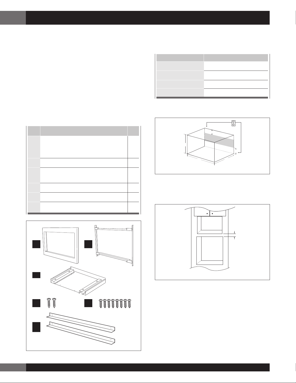
ITEM PART NAMES QTY
Front Frame: FDECAB265MRK0
A
W x H x D: 29
7
⁄8” x 18 1⁄2” x 1 3⁄16”
1
(759 x 470 x 30.2 mm)
B
Back Frame: FDECAB266MRK0 1
Exhaust Duct Assembly:
C
PDUC-B185MRP0A
D
Screw D: XTSS740P20000 2
E
Screw E: XOPS740P16000 8
1
STEP 1 - CABINET OR WALL OPENING
The opening in the wall or cabinet must be within the
following dimensions:
CUT OUT DIMENSIONS
A (Height)
B (Width)
C (Minimum Depth)
D
Outlet should NOT be in the shaded area as indicated on
Sketch 1.
A
B
Sketch 1
NOTES
• Please allow minimum 3" (76 mm) wood gap between
the microwave oven cutout and the appliance cutout
below the microwave oven. See Sketch 2.
17” (432 mm)
1
25
20” (508 mm)
4” (101.6 mm)
D
C
⁄4” (641 mm)
D
F
Air Deflector: PREF-B035MRP0 2
A B
C
D
E
F
Microwave cutout
3"
Wall oven cutout
Min.
Sketch 2
• If the dimension of DEPTH (C) is more than 21" (533.4
mm), the outlet location may be any area on the rear wall.
• The floor of the opening should be constructed of
plywood strong enough to support the weight of the oven
and floor load (about 100 pounds/45 KG). The floor
should be level and 90˚ with the face of the cabinet for
proper installation and operation of the oven. Be sure
to check the local building code as it may require that
the opening be enclosed with sides, ceiling and rear
partition. The proper functioning of the oven does not
require the enclosure.
2
Page 3
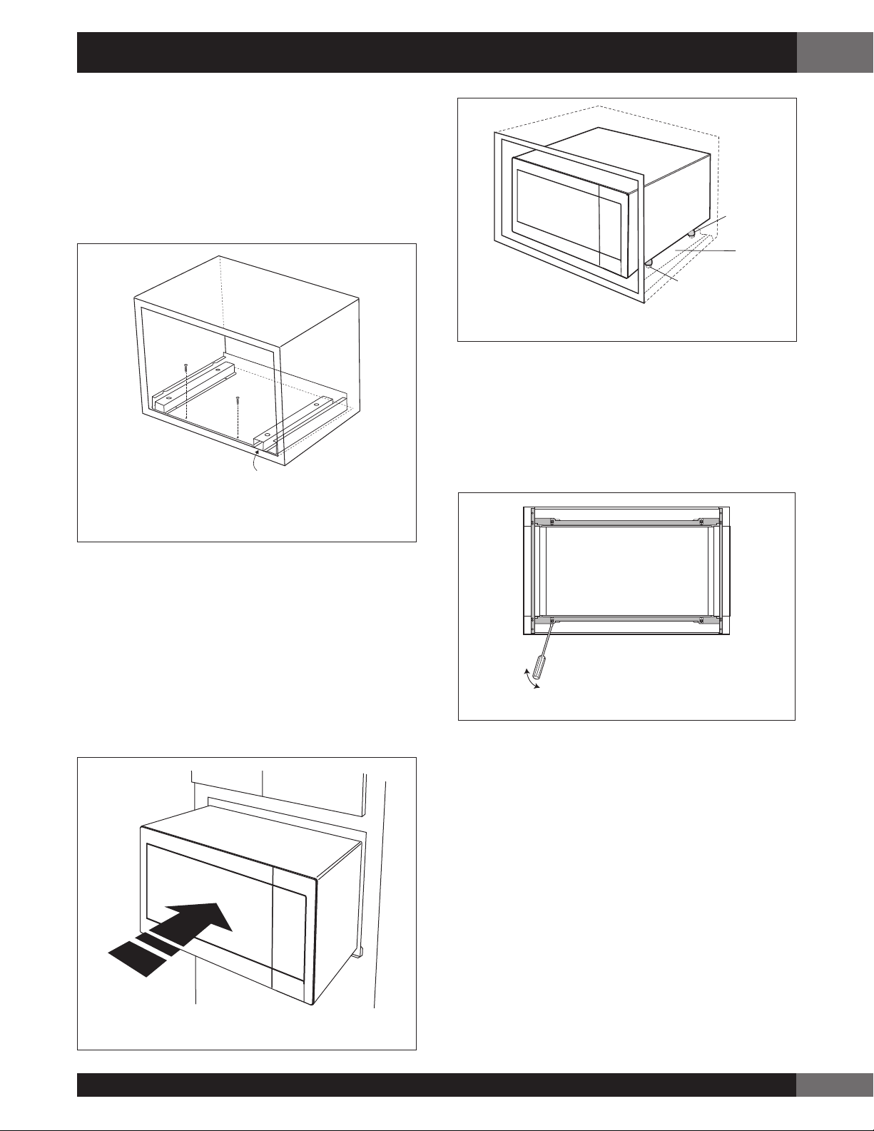
STEP 2 - EXHAUST DUCT ASSEMBLY
INSTALLATION
1. Place the Exhaust Duct Assembly in the center of the
opening. Align the front edge of the duct with the front
of the cabinet.
2. Secure the Exhaust Duct Assembly with two Screws D.
See Sketch 3.
Standard Installation Guide
Foot
Exhaust
duct
assembly
Duct recess
Sketch 5
EN
Screw D
Screw D
Exhaust duct assembly
right side aligns to front
edge of shelf
Sketch 3
STEP 3 - FRAME INSTALLATION
1. Place the oven adjacent to the wall or cabinet opening.
Plug the power cord into the electrical outlet.
2. Carefully guide the assembled oven into the prepared
opening. Slide the oven on the Exhaust Duct Assembly.
See Sketch 4. Avoid pinching the cord between the
oven and the wall. Adjust the position of the oven so
that the feet of the oven are fitted into the recesses of the
Exhaust Duct Assembly and door will open properly. See
Sketch 5.
3. Disassembly: The Front Frame and Back Frame come
pre-assembled with ball studs engaged in the receivers.
Separate the Front Frame from the Back Frame. Place
the assembly face down on a protected surface. At the
location of the ball stud, insert a flat head screwdriver
between the Front Frame and the Back Frame and gently
pry up to disengage the ball stud from the receiver.
Repeat for each corner. See Sketch 6.
Sketch 6
Sketch 4
3
Page 4

EN
Standard Installation Guide Flush Installation Guide
4. Back Frame Installation: Position back frame equal space
top to bottom, side to side. Mark for 4 holes, center
punch and pre-drill with 1⁄16” drill bit. Secure frame with
4 Screws (E). See Sketch 7.
Screw E
Screw E
Mounting holes
Equal gap
side to side
Mounting holes
Equal gap top, bottom
Mounting holes
Screw E
Screw E
Mounting holes
Sketch 7
5. Front Frame Installation: Place the Front Frame
onto the Back Frame and align ball studs and
receivers. Secure the Front Fram to the Back Frame
by firmly pushing the front frame onto the back
frame engaging the four (4) snap attachments. See
Sketch 8.
STEP 1 - CABINET OR WALL OPENING
The opening in the wall or cabinet must be within the
following dimensions:
CUT OUT DIMENSIONS
1
⁄4” (641.4 mm)
A
B
C
D
E
F
G
Outlet should NOT be in the shaded area H as indicated
on Sketch 1.
25
1
30
5
20
7
2
⁄16” (62 mm)
3
⁄4” (45 mm)
1
3
1
⁄16” (30.2 mm)
4” (101.6 mm)
Top View
A
B
⁄8” (765.2 mm)
⁄16” (516.7 mm)
Mounting
cleat
Shelf
F
Cabinet
face
Sketch 8
Front View
G
D D
Shelf
Bottom of flush cutout
E
C
H
G
Sketch 1
NOTES
7
Dimension C above will result in
⁄8 ” (23 mm) spaces
above and below the trim to allow for necessary intake and
exhaust air flow to ensure appliance does not overheat. Do
not reduce this spacing as in will void the warranty for any
issues resulting from a lack of airflow.
4
Page 5

Flush Installation Guide
(76 MM)
EN
NOTES
• Please allow minimum 3" (76 mm) wood gap between
the microwave oven cutout and the appliance cutout
below the microwave oven. See Sketch 2.
Microwave cutout
3"
Wall oven cutout
Min.
Sketch 2
• If the dimension of DEPTH (C) is more than 21" (533.4
mm), the outlet location may be any area on the rear wall.
• The floor of the opening should be constructed of
plywood strong enough to support the weight of the oven
and floor load (about 100 pounds/45 KG). The floor
should be level and 90˚ with the face of the cabinet for
proper installation and operation of the oven. Be sure
to check the local building code as it may require that
the opening be enclosed with sides, ceiling and rear
partition. The proper functioning of the oven does not
require the enclosure.
STEP 3 - FRAME INSTALLATION
1. Place the oven adjacent to the wall or cabinet opening.
Plug the power cord into the electrical outlet.
2. Carefully guide the assembled oven into the prepared
opening. Slide the oven on the Exhaust Duct Assembly.
See Sketch 4. Avoid pinching the cord between the
oven and the wall. Adjust the position of the oven so
that the feet of the oven are fitted into the recesses of the
Exhaust Duct Assembly and door will open properly. See
Sketch 5.
Screw D
Screw D
Sketch 4
STEP 2 - EXHAUST DUCT ASSEMBLY
INSTALLATION
1. Place the Exhaust Duct Assembly in the center of the
opening. Align the front edge of the duct with the front
of the cabinet. Align the front edge of the right side of
the duct with the front of the shelf. See Sketch 3.
2. Secure the Exhaust Duct Assembly with two Screws D.
See Sketch 3.
Screw D
Screw D
Exhaust duct assembly
right side aligns to front
edge of shelf
Sketch 3
Sketch 5
Duct recess
Foot
Exhaust
duct
assembly
5
Page 6

EN
Flush Installation Guide
3. Disassembly: The Front Frame and Back Frame come
pre-assembled with ball studs engaged in the receivers.
Separate the Front Frame from the Back Frame. Place
the assembly face down on a protected surface. At the
location of the ball stud, insert a flat head screwdriver
between the Front Frame and the Back Frame and gently
pry up to disengage the ball stud from the receiver.
Repeat for each corner. See Sketch 6.
Sketch 6
4. Back Frame Installation: Position back frame equal
space top to bottom, side to side. Mark for 4 holes on the
1
installed wood cleats, center punch and pre-drill with
⁄16”
drill bit. Secure frame with 4 Screws (E). See Sketch 7.
Mounting holes
Screw E
Mounting holes
Screw E
right) the Air Deflectors above and below the installed
Back Frame. See Sketch 8. Mark holes and pre-drill with
1
⁄16” drill bit.
Sketch 8
6. Front Frame Installation: Place the Front Frame
onto the Back Frame and align ball studs and
receivers. Secure the Front Fram to the Back Frame
by firmly pushing the front frame onto the back
frame engaging the four (4) snap attachments. See
Sketch 9.
Equal gap
side to side
Screw E
Mounting holes
Equal gap top, bottom
Screw E
Mounting holes
Snap
Attachment
Sketch 7
5. Install Air Deflectors top and bottom. Center (left and
Sketch 9
French Translation of this document can be found on our website https://www.fulgor-milano.us/.
6
Page 7

Page 8

YOUR LIFE | OUR PASSION
www.fulgor-milano.com/us
TINSEB574MRR0 _ 09-16-19
 Loading...