

Page 1

A Series BIOS
A Series BIOS
BIOS SETUP UTILITY
The BIOS Setup Utility is a program that sets up the
operating environment for your notebook. Your BIOS
is set at the factory for normal operating conditions,
therefore there is no need to set or change the BIOS
environment to operate your notebook.
The BIOS Setup Utility configures:
■
Device control feature parameters, such as changing
I/O addresses and boot devices.
■
System Data Security feature parameters, such
as passwords.
Entering the BIOS Setup Utility
To enter the BIOS Setup Utility do the following:
1. Turn on or restart your notebook.
2. Press the [F2] key once the Fujitsu logo appears
on the screen. This will open the main menu
of the BIOS Setup Utility with the current
settings displayed.
3. Press the [RIGHT ARROW] or [LEFT ARROW] key
to scroll through the other setup menus to review or
alter the current settings.
Navigating Through The Setup Utility
The BIOS setup utility consists of seven menus: Main,
Advanced, Security, Power, Boot, Info, and Exit. This
document explains each menu in turn, including all
submenus and setup items.
The following procedures a l low you to navigate the
setup utility menus:
1. To select a menu, use the cursor keys: .
2. To select a field within a menu or a submenu, use the
cursor keys: , .
3. To select the different values for each field, press the
[Spacebar] or [+] to change to the next higher selection and [F5] or [-] to go to the next lower selection.
,
4. To activate a submenu press the [Enter] key.
5. To return to a menu from a submenu, press
the [Esc] key.
6. To go to the Exit m e nu from any other menu,
press the [Esc] key.
POINT
Selecting a field causes a hel p message about that field
to be displayed on the right-hand side of the screen.
POINT
Pressing the Enter key with the highlight on a selection
that is not a submenu or auto selection will cause a list
of all options for tha t item to be displayed. Pressing the
Enter key again will select the highlighted choice.
7. Pressing the [F9] key resets all items in the BIOS to
the default values.
8. Pressing the [F10] key saves the current configuration and exits the BIOS Setup Utility. You will be
asked to verify this selection before it is executed.
9. Pressing the [F1] key gives you a general help screen.
Entering the Setup Utility After a Configuration
Change or System Failure
If there has been a change in the system configuration
that does not agree with the parameter settings stored
in your BIOS memory, or there is a failure in the system,
the system beeps and/or displays an error message after
the Power On Self Tes t (P OS T ) . If the failure is no t
too severe, it will give you the opportunity to modify
the settings of the setup utility, as described in the
following steps:
1. When you turn on or restart the computer there is
a beep and/or the following message appears on
the screen:
Error message - please run SETUP
program Press <F1> key to continue,
<F2> to run SETUP
1
Page 2

LifeBook A Series BIOS
2. If an error message is displayed on the screen, and
you want to continue with the boot process and start
the operating system anyway, press the [F1] key.
CAUTION
If your notebook emits a series of beeps that sounds like
a code and the display is blank, please refer to the Troubleshooting Section. The Troubleshooting Section
includes a list of error messages and their meanings.
POINT
If your data security settings require it, you may be
asked for a password before the operating system will
be opened.
3. If an error message is displayed on the screen, and
you want to enter the setup utility, press the [F2] key.
4. When the setup utility starts with a fault present, the
system displays the following message:
Warning!
Error message
[Continue]
5. Press any key to enter the setup utility. The system
will then display the Main Menu with current
parameters values.
2
Page 3
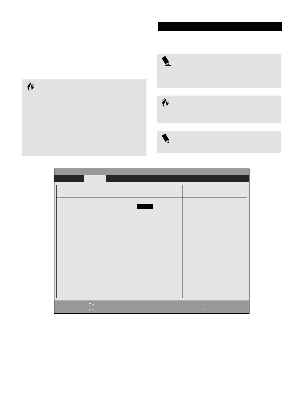
Main Menu
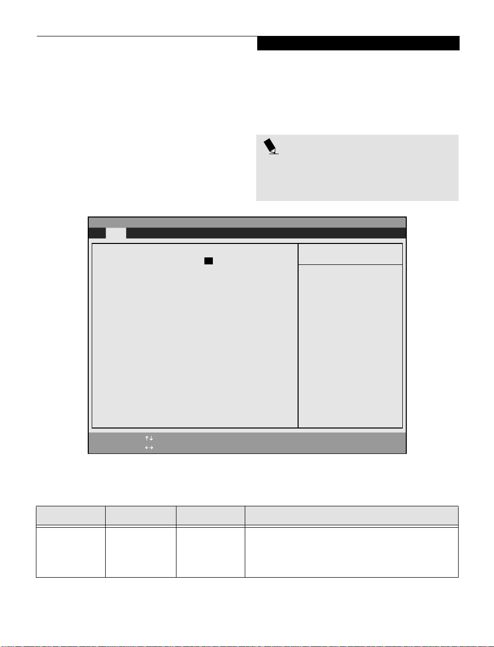
MAIN MENU – SETTING STANDARD SYSTEM PARAMETERS
The Main Menu allows you to set or view the current
system parameters. Follow the instructions for Navigating Through The Setup Utility to make any changes.
(See Navigating Through The Setup Utility on page1 for
more information.)
The following tables show the names of the menu fields
for the Main menu and its submenus, all of the options
for each field, the default settings and a description of
PhoenixBIOS Setup Utility
Main Advanced Security Power Boot Info Exit
System Time: [02:34:56]
System Date: [07/27/2000]
Legacy Diskette A: [1.44/1.2 MB, 3.5"]
▲
Primary Master [6007MB]
Secondary Master: CD-ROM
System Memory: 640 KB
Extended Memory: 63 MB
Language: [English (US)]
the field’s function and any special information needed
to help understand the field’s use.
Note that actual drive labels shown may vary.
POINT
System Time and System Date can also be set from your
operating system without using the setup utility. Use
the calendar and time icon on your Windows Control
panel or type time or date from the MS-DOS prompt.
Item Specific Help
<Tab>, <Shift-Tab>, or
<Enter> selects field.
F1 Help
ESC Exit
Select Item
Select Menu
-/Space Change Values
Enter Select Sub-Menu
Figure 1 Main Menu
▲
F9 Setup Defaults
F10 Save and Exit
Table 1: Fields, Options and Defaults for the Main Menu
Note that the parameters listed below may differ, as determined by your system configuration.
Menu Field Options Default Description
System Time: –— –— Sets and displays the current time. Time is in a 24 hour format
of hours:minutes:se co nd s with 2 di gits for each. (HH:MM:SS).
Example: 16:45:57. You may change each segment of the time
separately. Move between the segments with the [Tab] key and/or
[Shift] + [Tab] keys.
3
Page 4

LifeBook A Series BIOS
Table 1: Fields, Options and Defaults for the Main Menu
Note that the parameters listed below may differ, as determined by your system configuration.
Menu Field Options Default Description
System Date: Display only –— Sets and displays the current date. Date is in a month/day/year
numeric format with 2 digits each for month and day and 4 digits
for year. (MM/DD/YYYY) for example: 03/20/1998. You may
change each segment of the date separately. Move between the
segments with the [Tab] key and/or [Shift] + [Tab] keys.
Legacy Diskette A:
Primary Master
Display only
■
Selects Primary
Master submenu
[1.44/1.2MB
3 1/2"]
The size of the
hard drive
Displays the legacy diskette device size.
Display the size of the primary master device. Pressing the Enter key
selects the Primary Master submenu allowing additional device
configuration options for this interface.
Secondary Master:
System Memory:
Extended Memory:
Language:
Display only
Display only
Display only
■
English (US)
■
Japanese (JP)
CD-ROM Display the type of device on this ATA/ATAPI interface, if there is
one.
640 KB Displays the size of installed system memory.
63 KB Displays the size of the system’s extended memory.
[English (US)] The default setting differs between the US/European and the
Japanese model. Selects the display language for the BIOS.
4
Page 5
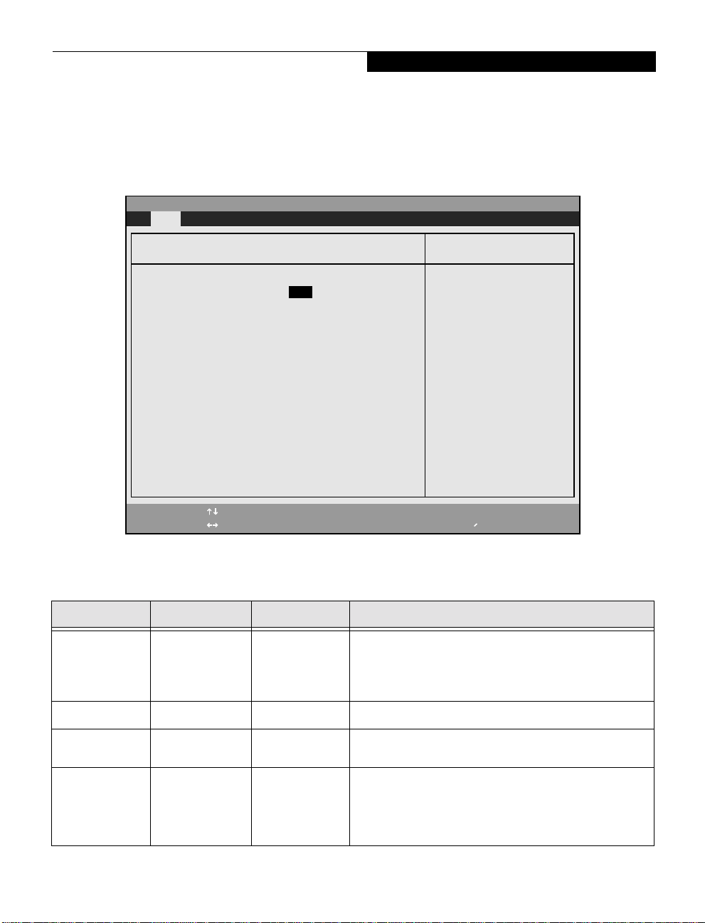
Primary Master Submenu of the Main Menu
The Primar y Master subm enu i den tifies what ATA
devices are installed.
PhoenixBIOS Setup Utility
Main
Main Menu
Note that actual hard drive label shown may vary.
Depending on the drive type, information such as cylinders, heads and sectors may also be displayed.
Primary Master [TOSHIBA MK6014MAP-(PM)]*
Type: [Auto]
Total Sectors: 11733120
Maximum Capacity: 6007MB
Item Specific Help
User = you enter
parameters of hard-disk
drive installed at this
connection.
Multi-Sector Transfers: [16 Sectors]
LBA Mode Control: [Enabled]
Transfer Mode: [Fast PIO 4]
Ultra DMA Mode: [Mode 2]
Auto = autotypes
ATA/ATAPI drive
installed here.
CD-ROM = a CD-ROM drive
is installed here.
F1 Help
ESC Exit
Select Item
Select Menu
Figure 2 Primary Master Submenu
-/Space
Enter
Change Values
▲
Select Sub-Menu
F9 Setup Defaults
F10 Save and Exit
Table 2: Fields, Options and Defaults for the Primary Master Submenu of the Main Menu
Menu Field Options Default Description
Type:
■
Auto
■
None
■
CD-ROM
■
User
[Auto] Selects the ATA/ATAPI device type. Select Auto to have the type
automatically identified by the BIOS at POST. If None is selected, all
of the following Set-up items do not appear. Select CD-ROM if a
CD-ROM drive is installed at this connection. Select User to allow
the user to enter the parameters of the hard disk drive.
Total Sectors:
Maximum
Capacity:
Multi-Sector
Transfers:
■
Display only 11733120 Displays the total number of sectors available on the hard drive.
■
Display only 6007MB Displays the maximum capacity of the drive calculated from the
■
Disabled
■
2 Sectors
■
4 Sectors
■
8 Sectors
■
16 Sectors
[16 Sectors] This option cannot be changed when Auto is selected. Specify the
parameters of th e hard disk.
number of sectors per block for multiple sector transfer. MAX refers
to the size the disk returns when required.
5
Page 6
LifeBook A Series BIOS
Table 2: Fields, Options and Defaults for the Primary Master Submenu of the Main Menu
Menu Field Options Default Description
LBA Mode
Control:
Transfer Mode:
Ultra DMA Mode:
■
Disabled
■
Enabled
■
Standard
■
Fast PIO 1
■
Fast PIO 2
■
Fast PIO 3
■
Fast PIO 4
■
Fast PIO 3/DMA
■
Fast PIO 4/DMA
■
Disabled
■
Mode 0
■
Mode 1
■
Mode 2
■
Mode 3
■
Mode 4
[Enabled] Enables or disables Logical Block Addressing i n pl ace of Cylinder,
[Fast PI0 4] Selects the method for moving data to/from the drive. Autotype
[Mode 2] Selects the method for moving data to/from the drive. Autotype
CAUTION
A bootable CD-ROM may have either a floppy disk format or a hard drive format. When the bootable CDROM is used, the drive allocations change automatically
without changing the BIOS setup. If a floppy disk format CD-ROM is used, the CD-ROM becomes Drive A.
The CD-ROM will only take drive C: (hard drive format)
if the internal hard drive is not present or is disabled.
The bootable CD-ROM can never use a C: designation
if a formatted internal hard drive is present, since the C:
designator is always reserved for the internal hard
drive.The boot sequence ignores the new drive designations; however, your application software will use the
new designations.
Head, Sector addressing. This option cannot be changed when
Auto is selected.
the drive to select the optimum transfer mode. This option cannot
be changed when Auto is selected.
the drive to select the optimum transfer mode. This option cannot
be changed when Auto is selected.
CAUTION
Be careful of the operating environment when booting
from a CD-ROM or you may overwrite files by mistake.
Exiting from Main Menu
When you have finished setting the parameters on this
menu, you can either exit from the setup utility, or move
to another menu. If you wish to exit from the setup
utility, press the [Esc] key or use the cursor keys to go to
the Exit menu. If y ou wish t o mov e to another menu, u se
the cursor keys.
6
Page 7
Main Menu
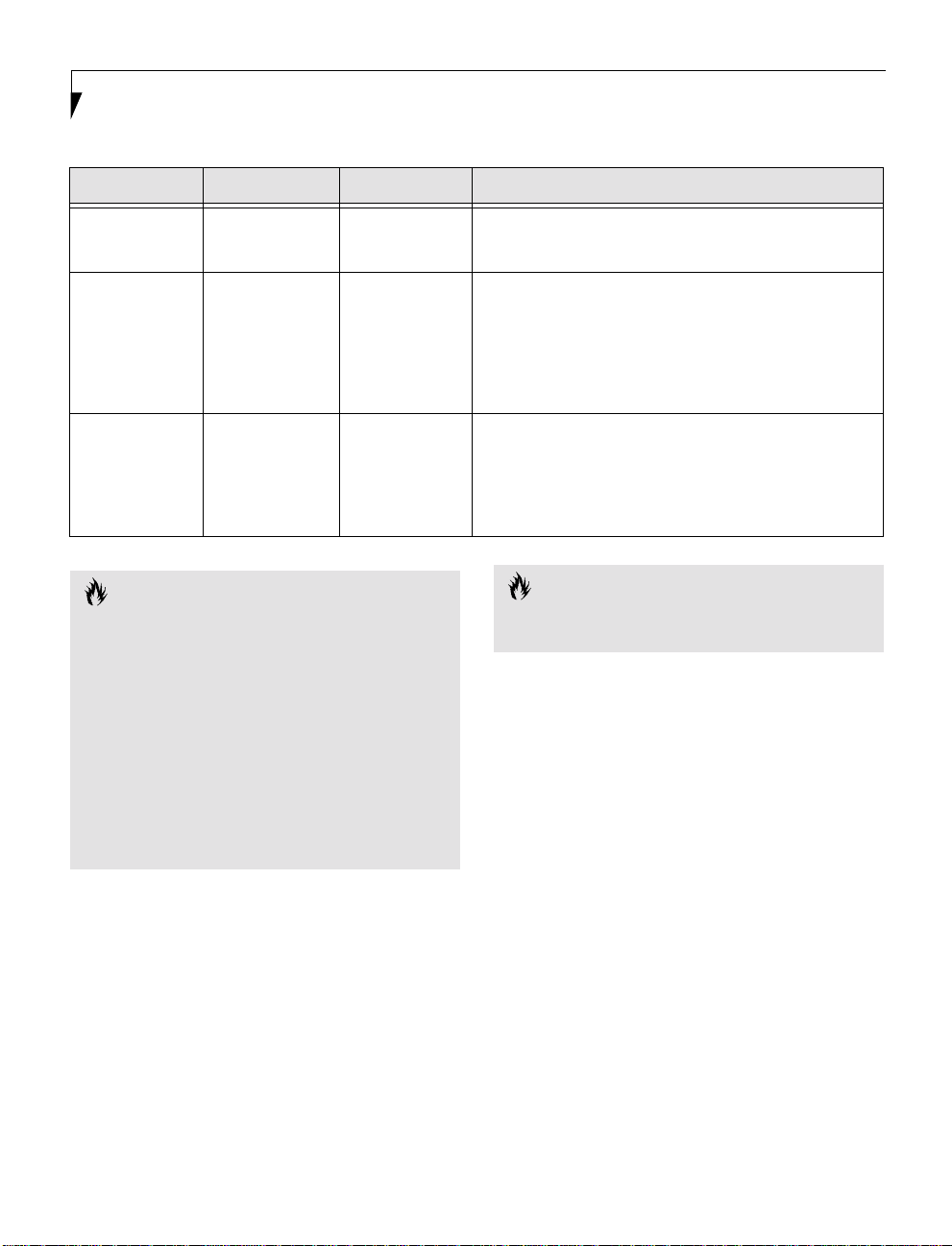
ADVANCED MENU – SETTING DEVICE FEATURE CONTROLS
The Advanced Menu allows you to:
■
Enable or d is a ble support fo r Pl ug & Play
operating systems.
■
Set the I/O addresses for the serial and parallel ports.
■
Set the commu nication mode for the parallel and
infrared ports.
■
Set the features of the keyboard/mouse.
■
Select between the display panel and an external
CRT display.
■
Enable or disable compensation for your di splay.
■
Configure PCI devices in your system.
■
Configures DMI Event Logging.
PhoenixBIOS Setup Utility
Main Advanced Security Power Boot Info Exit
Plug & Play O/S:
▲ ▲ ▲ ▲ ▲
I/O Device Configuration
Keyboard/Mouse Features
Video Features
PCI Configuration
DMI Event Logging
Follow the instructions for Navigating Through the
Setup Ut ility to mak e any chan g e s.
(See Navigating Through The Setup Utility on page 1 for
more information.)
The following tabl e s show th e nam es of the menu fields
for the Advanced Menu and its submenus, all of the
options for each field, the default settings and a description of the field’s function and any special information
needed to help understand the field’s use.
Note that not all fields appear in all configurations; the
fields that appear are dependent upon the system CPU.
Item Specific Help
[Yes]
Select 'Yes' if you
are using a Plug &
Play capable
operating system.
Select 'No' if you
need the BIOS to
configure non-boot
devices.
F1 Help
ESC Exit
Select Item
Select Menu
-/Space
Figure 3 Advanced Menu
Change Values
Enter
▲
Select Sub-Menu
F9 Setup Defaults
F10 Save and Exit
7
Page 8

LifeBook A Series BIOS
Table 3: Fields, Option s an d Defau lts for the Ad van c ed Men u
Menu Field Options Default Description
Plug & Play O/S:
I/O Device
Configuration
■
No
■
Yes
[Yes] Select Yes if you are using a Plug & Play-capable operating system.
Select No if you need the BIOS to configure non-boot devices.
–— –— When selected, opens the I/O Device Configuration submenu
which allows the user to modify settings for serial, infrared and
parallel ports.
Keyboard/Mouse
Features
–— –— When selected, opens the Keyboard/Mouse Features submenu,
which allows setting external and internal keyboard and
mouse parameters.
Video Features –— –— When selected, opens the Video Features submenu, which allows
setting of the display parameters, including routing of video signals
to different displays.
PCI Configurations –— –— When selected, opens addi tio nal me nu s to confi gure PCI de vice s.
DMI Event
–— –— When selected, opens the event logging submenu.
Logging
8
Page 9
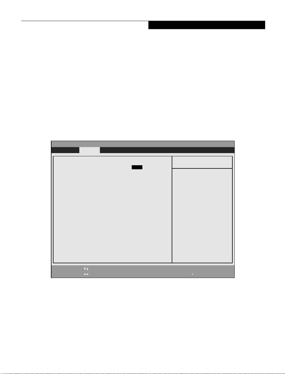
I/O Device Configuration Submenu of the Advanced Menu
The I/O Device Configuration submenu provides the
ability to set the I/O addresses and interrupt levels for
the serial, infrared, and parallel ports of your notebook.
CAUTION
I/O addresses, DMA channels, and Interrupt levels can
be entered in various ways, including via the BIOS setup
utility, the control software for the I/O device, or the
hardware. If any two ports or devices, serial or parallel,
have the same I/O address assigned, your notebook will
not function normal ly. Please keep a record of original
settings before making any changes in the event that a
restoration is required. See your hardware and software
documentation as well as the setup utility to determine
settings, limitations, etc.
PhoenixBIOS Setup Utility
Advanced
To prevent IRQ and address conflicts, avoid changing
the default settings. If you must change the settings,
you can call 1-800-8FUJITSU for technical assistance.
CAUTION
The BIOS will warn you of a resource conflict by placing
a yellow asterisk next to each device that is in conflict.
All I/O addresses in Table 4 are in hexadecimal.
Advanced Menu
POINT
POINT
I/O Device Configuration
Serial port A: [Enabled]
Base I/O address: [3F8]
Interrupt: [IRQ 4]
Serial port B: [Enabled]
Mode: [FIR]
Base I/O address: [2E8]
Interrupt: [IRQ 3]
DMA Channel: [DMA 3]
Parallel Port: [Enabled]
Mode: [Bi-directional]
Base I/O address: [378]
Interrupt: [IRQ 7]
Floppy disk controller: [Enabled]
IDE controller: [Both]
F1 Help
ESC Exit
Select Item
Select Menu
Figure 4 I/O Device Configuration Submenu
-/Space
Enter
Change Values
Select Sub-Menu
Item Specific Help
Configure serial port A
using options:
[Disabled]
No configuration
[Enabled]
User configuration
[Auto]
BIOS or OS chooses
configuration
▲
F9 Setup Defaults
F10 Save and Exit
9
Page 10

LifeBook A Series BIOS
Table 4: Fields, Options and Defaults for the I/O Device Configuration Submenu of the Advanced Menu
Menu Field Options Default Description
Serial port A:
Base I/O
address:
Interrupt:
Serial port B:
Mode:
Base I/O
address:
Interrupt:
DMA Channel:
Parallel Port:
Mode:
Base I/O
address:
Interrupt:
Floppy disk
controller:
IDE controller:
■
Disabled
■
Enabled
■
Auto
■
3F8
■
2F8
■
3E8
■
2E8
■
IRQ 3
■
IRQ 4
■
Disabled
■
Enabled
■
Auto
■
IrDA
■
FIR
■
3F8
■
2F8
■
3E8
■
2E8
■
IRQ 3
■
IRQ 4
■
DMA 1
■
DMA 3
■
Disabled
■
Enabled
■
Auto
■
Output Only
■
Bi-directional
■
ECP
■
378
■
278
■
3BC
■
IRQ 5
■
IRQ 7
■
Disabled
■
Enabled
■
Disabled
■
Primary
■
Secondary
■
Both
[Enabled] Configures Serial Port A using either no configuration (Disabled), a
user defined configuration (Enabled), or by allowing the BIOS or OS
to choose the configurati o n (Auto).
[3F8] Allows user to set the serial port base I/O address when Serial Port
A is Enabled.
[IRQ 4] Allows user to set the Serial Port A interrupt when Serial Port A
is Enabled.
[Enabled] Configures the infrared port using either no configuration
(Disabled), a user defined configuration (Enabled), or by
allowing the BIOS or OS to choose the configuration (Auto).
[FIR] When the infrared port is enabled this option is available allowing
the user to set the mode for the infrared port.
[2E8] Allows user to set the infrared port I/O address when the
infrared port is Enabled.
[IRQ 3] Allows user to set the infrared port interrupt when the infrared
port is Enabled.
[DMA 3] Allows user to set the infrared port DMA Channel when the
infrared port is Enabled.
[Enabled] Configures the parallel port using either no configuration
(Disabled), a user defined configuration (Enabled), or by
allowing the BIOS or OS to choose the configuration (Auto).
[Bi-directional] When the parallel port is enabled this option is available allowing
the user to set the mode for the parallel port. Bi-directional allows
two-way transfer of information between your notebook and a
connected parallel device. Output Only (Half Duplex) allows
information to be transferred in only one direction, from your
notebook to the printer or similar device. ECP Mode allows
communication with the ECP class of parallel I/O devices.
[378] Allows user to set the parallel port base I/O address when the
parallel port is Enabled.
[IRQ 7] Allows user to set the parallel port i nterrupt when the parallel
port is Enabled.
[Enabled] Allows user to enable or disable the floppy disk controller.
[Both] Allows user to select either one or both integrated local bus IDE
adapters.
10
Page 11

Keyboard/Mouse Features Submenu of the Advanced Menu
The Keyboard/Mouse Features submenu is for setti n g
the parameters of the integra t ed a nd exter n a l mouse
and keyboard.
PhoenixBIOS Setup Utility
Advanced Security Power Savings Exit
Advanced Menu
Keyboard/Mouse Features
Numlock:
Internal Pointing Device:
F1 Help
ESC Exit
Select Item
Select Menu
Figure 5 Keyboard/Mouse Features Submenu
[Auto]
[Auto Disabled]
-/Space
Change Values
Enter
Select Sub-Menu
▲
Item Specific Help
Select Power-on state
for Numlock.
F9 Setup Defaults
F10 Save and Exit
T able 5: Fields, Options and Defaults for the Keyboard/Mouse Submenu of the Advanced Menu
Menu Field Options Default Description
Numlock:
■
Auto
■
On
■
Off
[Auto] Sets the NumLock function state when the computer
completes booting.
Internal Pointing
Device:
■
Auto Disabled
■
Manual Setting
■
Always Enabled
■
Always Disabled
[Auto Disabled] Sets the device controlling the mouse cursor on the screen. Auto
Disabled disables the internal pointing device when an external
pointing device is connected to the PS/2 port. Manual Setting
allows the device to be enabled or disabled by a Hot Key. Always
Enabled makes the pointing device always enabled whether there is
an external mouse or not. Always Disabled makes the pointing
device always disabled whether there is an external mouse or not.
11
Page 12

LifeBook A Series BIOS
Video Features Submenu of the Advanced Menu
The Video Features Submenu is for setting the
display parameters.
PhoenixBIOS Setup Utility
Main Advanced Security Power Savings Exit
Video Features
Display: [Flat Panel]
Item Specific Help
Select display terminal.
Compensation: [Disabled]
TV Output: [Disabled]
TV Standard: [NTSC]
F1 Help
ESC Exit
Select Item
Select Menu
Figure 6 Video Features Submenu
-/Space
Enter
Change Values
▲
Select Sub-Menu
F9 Setup Defaults
F10 Save and Exit
Table 6: Fields, Options and Defaults for the Video Features Submenu of the Advanced Menu
Menu Field Options Default Description
Display:
Compensation:
■
Flat Panel
■
CRT
■
Simultaneous
■
Disabled
■
Enabled
[Flat Panel] Selects where the video signal will be routed.
[Disabled] Enables or disables compensation which controls spacing on the
display. When enabled, displays with less than pixel resolution
1024 x 768 or 800 x 600 will still cover the entire screen.
TV Output:
TV Standard:
12
■
Disabled
■
Enabled
■
NTSC
■
PAL
[Disabled] Allows you to enable or disable TV output.
[NTSC] Allows you to select a TV standard.
Page 13

PCI Configuration Submenu of the Advanced Menu
The PCI Configuration submenu allows the user to
reserve specific interrupts (IRQs) for legacy ISA devices,
and to enable or disable built in PCI device modules.
PhoenixBIOS Setup Utility
Main Advanced Security Power Savings Exit
Advanced Menu
PCI Configuration
▲
IRQ Reservation
Item Specific Help
Reserve specific IRQs
for use by legacy ISA
devices.
F1 Help
ESC Exit
Select Item
Select Menu
Figure 7 PCI Configuration Submenu
-/Space
Enter
Change Values
▲
Select Sub-Menu
F9 Setup Defaults
F10 Save and Exit
Table 7: Fields, Option s an d Defau lts for the PCI Configuration Submenu of the Advanced Menu
Menu Field Options Default Description
IRQ Reservation –— –— Reserve specific IRQs for use by legacy ISA devices.
13
Page 14

LifeBook A Series BIOS
IRQ Reservation Submenu of the PCI Configuration Submenu
The IRQ Reservation submenu o f the PCI Configuration
submenu allows the user to m ar k various IRQs as
reserved for use by legacy ISA devices. Wh en an IRQ
is reserved, the BIOS does not use it for embedded PCI
or ISA dev ices.
PhoenixBIOS Setup Utility
Main Advanced Security Power Savings Exit
Main Advanced Security Power Savings Exit
PhoenixBIOS Setup Utility
CAUTION
Only IRQ's 9, 10, & 11 can be reserved without conflict.
IRQ Reservation
IRQ Reservation
IRQ 3: [Available]
IRQ 3: [Available]
IRQ 4: [Available]
IRQ 4: [Available]
IRQ 5: [Available]
IRQ 5: [Available]
IRQ 7: [Available]
IRQ 7: [Available]
IRQ 9: [Available]
IRQ 9: [Available]
IRQ 10: [Available]
IRQ 10: [Available]
IRQ 11: [Available]
IRQ 11: [Available]
Item Specific Help
Item Specific Help
Reserves the specified
Reserve the specified
IRQ for use by legacy
IRQ for use by legacy
ISA devices.
ISA devices.
IRQ 15: [Available]
F1 Help
F1 Help
ESC Exit
ESC Exit
Select Item
Select Item
Select Menu
Select Menu
Figure 8 IRQ Reservation Submenu
-/Space
-/Space
Enter
Enter
Change Values
Change Values
▲
▲
Select Sub-Menu
Select Sub-Menu
F9 Setup Defaults
F9 Setup Defaults
F10 Save and Exit
F10 Save and Exit
Table 8: Fields, Options and Defaults for the IRQ Reservation Submenu of the
PCI Configuration Submenu of the Advanced Menu
Menu Field Options Default Description
IRQ 3:
■
Available
■
Reserved
[Available] Reserves IRQ 3. If Reserved is selected, the BIOS reserves IRQ 3 for
use by legacy ISA devices and does not use it for embedded PCI or
ISA devices. IRQ 3 is removed from the IRQ bitmap in the PCI IRQ
routing table.
14
IRQ 4:
IRQ 5:
IRQ 7:
■
Available
■
Reserved
■
Available
■
Reserved
■
Available
■
Reserved
[Available] Reserves IRQ 4.
[Available] Reserves IRQ 5.
[Available] Reserves IRQ 7.
Page 15

Advanced Menu
Table 8: Fields, Options and Defaults for the IRQ Reservation Submenu of the
PCI Configuration Submenu of the Advanced Menu
Menu Field Options Default Description
IRQ 9:
IRQ 10:
IRQ 11:
■
Available
■
Reserved
■
Available
■
Reserved
■
Available
■
Reserved
[Available] Reserves IRQ 9.
[Available] Reserves IRQ 10.
[Available] Reserves IRQ 11.
15
Page 16

LifeBook A Series BIOS
DMI Event Logging Submenu of the Advanced Menu
The DMI Event Logging Submenu configures event logging features for DMI events.
PhoenixBIOS Setup Utility
Main Advanced Security Power Savings Exit
DMI Event Logging
Event log capacity: Space Available
Event log validity: Valid
View DMI event log: [Enter]
Item Specific Help
View the contents of
the DMI event log.
Clear all DMI event log: [No]
Event Logging: [Enabled]
System Boot Event: [Enabled]
F1 Help
ESC Exit
Select Item
Select Menu
Figure 9 DMI Event Logging Submenu
-/Space
Enter
Change Values
▲
Select Sub-Menu
F9 Setup Defaults
F10 Save and Exit
Table 9: Field s, Op tions and Defaults for the DMI Event Logging Submenu of the Advanced Menu
Menu Field Options Default Description
Event log
capacity
Space Available Display only
Event log validity Valid Display only
■
View DMI event
log
Clear all DMI event
log:
Event Logging:
System Boot
Event:
16
Enter [Ente r] Allows you to view content of event log
■
No
■
Yes
■
Disabled
■
Enabled
■
Disabled
■
Enabled
[No] When set to [Yes] all event logs will be cleared at next boot.
[Enabled] Turns event logging on and off for all DMI events.
[Enabled] Turns event logging on and off for DMI system boot events.
Page 17

Advanced Menu
SECURITY MENU – SETTING THE SECURITY FEATURES
The Security menu allows you to set up the data security
features of your not ebook t o fi t yo ur o perating needs and
to view the current data security configuration. Follow the
instructions for Navigating Through the Setup Utility to
make any changes. (See Navigating Through The Setup
Utility on page 1 for more information.)
The following tables show the names of the menu
fields for the Security menu and i ts submenus, all of
the options for each field, the default settings and a
description of the field's function and any special
information needed to help understand the field's use.
The default condition is no passwords required and
no write protection.
CAUTION
Entering a password incorrectly 3 times in a row will
cause the keyboard and mouse to be locked out and the
warning
happens restart the computer by turning off and on the
power with the power switch and use the correct
password on reboot.
[System Disabled]
Main Advanced Security Power Boot Info Exit
Supervisor Password Is: Clear
User Password Is: Clear
to be displayed. If this
PhoenixBIOS Setup Utility
POINTS
■
If you set a password , write it down and k ee p it in a
safe place. If you forget the password, you will have
to contact your support representative to regain
access to your secured functions and data.
■
If you make an error when re-entering the password a [Warning] will be displayed on the
screen. To try again press the Enter key and then
retype the password. Press the Esc key to abort the
password setti ng proces s.
■
Boot sector protec tion mu st be set to [Normal]
to install or upgr a de an op erating system.
Item Specific Help
Set Supervisor Password [Enter]
Set User Password [Enter]
Diskette access: [All]
Password on Boot: [Disabled]
Power Management Security: [Disabled]
Fixed disk boot sector: [Normal]
Fixed disk security
Primary Master: [Disabled]
F1 Help
ESC Exit
Select Item
Select Menu
-/Space
Enter
Figure 10 Security Menu
Supervisor Password
controls access to the
setup utility.
Change Values
▲
Select Sub-Menu
F9 Setup Defaults
F10 Save and Exit
17
Page 18

LifeBook A Series BIOS
Table 10: Fields, Options and Defaults for the Security Menu
Menu Field Options Default Description
Supervisor
Password is:
–— Clear A display-only field. Set is displayed when the system supervisor
password is set and Clear when it is not.
User Password is: –— Clear A display-only field. Set is displayed when the general user
password is set, and Clear when it is not.
Set Supervisor
Password
–— [Enter] Sets, changes or cancels the Supervisor Password. The Supervisor
Password may be up to seven characters long and must include
only letters or numbers (no symbols). Passwords are NOT casesensitive. To cancel a password press the Enter key instead of
entering characters in the Enter New Password field and in the
Re-enter New Password field. When a Supervisor Password is set
it must be used to access the BIOS setup utility.
Set User Password –— [Enter] This field can only be accessed if the Supervisor Password is set.
Sets, changes or cancels the User Password. The User Password
may be up to seven characters long and must include only letters
or numbers (no symbols ). Pass words are NOT c ase-s ens i tive. To
cancel a password press the Enter key instead of entering characters
in the Enter New Password field and in the Re-enter New Password
field. When a User Password is set it must be used to access the
BIOS setup utility.
■
Diskette access:
Password on Boot:
All
■
Supervisor Only
■
Disabled
■
Enabled
[All] Allows access to the diskette drive by either all users or the
supervis or only.
[Disabled] When set to DIsabled, no password is required. When set to
Enabled, a password (User or Supervisor) is required after the Power
On Self Test (POST) every time the system is booted (before the
operating system is read from the disk).
Power
Management
Security:
Fixed disk boot
sector:
■
Disabled
■
Enabled
■
Normal
■
Write Protected
[Disabled] When set to Enabled, a password is required upon Resume from
Suspend or Save to Disk Mode. This password is identical to the
power-on password.
[Normal] Sets protection mode for hard disk driv e.
Fixed disk security
Primary Master:
■
Disabled
■
Enabled
[Disabled] When Enabled is selected, the data on the hard disk is protected
Exiting from the Security Menu
When you have finished setting the parameters on the
Security Menu, you can either exi t from setup utility or
move to another menu. If you wi sh to exit from s etup
utility, press the Esc key to go to the Exit Menu. If you
wish to move to another menu, use the cursor keys.
18
with the password lock feature of the drive. You cannot read any
data on the drive if it is not installed in the same system with which
it was locked with the pas sw ord .
Page 19

Advanced Menu
POWER MENU – SETTING POWER MANAGEMENT FEATURES
The Power menu allows you to set and change the power
management parameters. Follow the instruct ions for
Navigating Through the Setup Utility to make any
changes. (See Navigating Through The Setup Utility on
page 1 for more information.)
The following tables show the names of the menu fields
for the Power menu and its submenus, all of the options
for each field, the default settings and a description of
the field's function an d any spec ial in formation neede d
to help understand the field's use.
POINT
In Windows 98 Auto-suspend Timeout, Hard Disk
Timeout, and Video Time out features are available
exclusively through the operating system.
POINT
When resuming f rom a Save -to- Di sk s usp ensio n th ere
will be a delay while the contents of system memory and
operating parameters are loaded from the hard drive.
CAUTION
In Save-to-Disk mode there is no indication on the
Status Indicator to let you know you are suspended
rather than shut off from the power switch. You may
want to make a habit of always trying the Suspend/
Resume button before using the power switch.
CAUTION
Resume on Modem ring when enabled will draw power
from the bridge battery alone when your system is
running off battery power. This may potentially drain
your bridge battery. Disabling Resume on Modem ring
will prevent this from happening.
19
Page 20

LifeBook A Series BIOS
Main Advanced Security Power Boot Info Exit
PhoenixBIOS Setup Utility
Power Savings: [Customized]
Hard Disk Timeout: [Off]
Video Timeout: [Off]
Idle Mode: [Off]
Standby Timeout: [4 Minutes]
Auto Suspend Timeout: [15 Minutes]
Suspend Mode: [Suspend]
Auto Save To Disk: [Off]
Resume On Modem Ring: [Off]
Resume On Time: [Off]
Resume Time: [00:00:00]
▲
Advanced Features
F1 Help
ESC Exit
Select Item
Select Menu
-/Space
Enter
Figure 11 Power Menu
Change Values
Select Sub-Menu
Table 11: Fields, Options and Defaults for the Power Menu
Menu field Options Default Description
Power Savings:
Hard Disk Timeout:
■
Disabled
■
Customized
■
Max. Power
Savings
■
Max.
Performance
■
Off
■
30 seconds t o 20
Minutes
[Customized] Sets the power savings parameters to a factory installed
[Off] Sets the length of time that the hard drive can be inactive before your
combination of parameters, a custom set of parameters set
by you or no power sav i ng feat ures.
notebook automatically turns off the power to the hard drive controller
and drive motor. If you choose a factory installed combination of
parameters this field will display the setting. If you choose to customize
the parameters you will be able to set this yourself. The options available
vary from Off, which has no inactivity shutoff, to 20 minutes.
Item Specific Help
Select Power Management
Mode. Choosing modes
changes system power
management settings.
Maximum Power Savings
conserves the greatest
amount of system power
while Maximum
Performance conserves
power but allows
greatest system
performance. To alter
these settings, choose
Customize. To turn off
power management,
choose Disable.
▲
F9 Setup Defaults
F10 Save and Exit
Video Timeout:
Idle Mode:
Standby Timeout:
20
■
Off
■
2 to 20 Minutes
■
Off
■
On
■
Off
■
1 to 16 Minutes
[Off] Sets the length of time without any user input activity before the display
[Off] Turning on Idle Mode slows down the CPU during brief periods when the
[4 Minutes] Sets the length of time without any user input device activity before the
is turned off. If you choose a factory combination of parameters, this
field will display the setting. If you choose to customize the parameters,
you will be able to set this yourself. Off has no inactivity shutoff.
system is not bu s y.
CPU is set to half speed and the display and the hard drive are turned off.
If you choose a factory combination of parameters this field will display
the setting. If you choose to customize the parameters you will be able to
set this yourself.
Page 21

Table 11: Fields, Options and Defaults for the Power Menu
Menu field Options Default Description
■
Auto Suspend
Timeout:
Suspend Mode:
Off
■
5 to 60 minutes
■
Suspend
■
Save to Disk
[15 Minutes] Sets the length of time without any I/O activity before your notebook
goes into Suspend mod e. If yo u choos e a factory combinatio n of
parameters this field will display that setting. If you choose to customize
the parameters you will be able to set this yourself. Off has no inactivity
suspension.
[Suspend] Sets the state of suspension used. If you choose Suspend, operation will
be suspended. Power will still be supplied to system memory, but
everything else will be powered down or will enter a very low power
state. If you choose Save-to-Disk, your notebook will save all of system
memory and operating parameters to the hard drive before turning your
notebook to the pseudo-off condition.
Advanced Menu
Auto Save
to Disk:
Resume On
Modem Ring:
■
Off
■
After 1 Hour
■
Off
■
On
[Off] When set to After 1 Hour your notebook will automatically save all
of system memory and the operating parameters to the hard drive and
go to the pseudo-off if you leave your notebook in Suspend mode for an
hour.
[Off] Determines whether to Resume from a suspension state when a message
is received by telephone line. This feature will not operate if the Save-toDisk mode is enabled. This feature applies to internal and external
modems.
Resume On Time:
Resume Time:
Off
■
On
■
00:00:00 to
23:59:59
[Off] Set s whether or not to res ume from a suspens ion st ate at a designat ed
time. This feature is available from either the Suspend mode or the Saveto-Disk mode.
[00:00:00] Sets the designated time, on a 24-hour clock, when the notebook is to
automatically resume operation from the Suspend state. The format of
■
the clock setting is hours:minutes:seconds. Each segment of the time is
set separately, either by incrementing or by typing in the numbers. You
move between the segments with the [T ab] key or the [Shift]+[Tab] keys.
This only applies when Resume on Time is set to On.
Advanced
Features:
–— –— When selected, opens the Advanced Feat ures submenu which
allows setting additional power saving parameters.
Factory Installed Values for Power Saving Profiles
Hard Disk
Timeout
Customized: Off Off 4 Minutes 15 Minutes
Maximum Power Savings: 30 Seconds 2 Minutes 1 Minute 5 Minutes
Video Timeout Standby
Timeout
Auto Suspend
Timeout
Maximum Performance: Off Off Off 15 Minutes
Disabled: Off Off Off Off
Sample Customized Profile: (To get even better battery
2 Minutes 1 Minute 1 M inut e 5 Minutes
life keep the display and volume settings as low as
possible and use the sample customized profile.)
21
Page 22

LifeBook A Series BIOS
Advanced Features Submenu of the Power Menu
The Advanced Features submenu i s for setting some
non-time related power saving parameters.
PhoenixBIOS Setup Utility
Power
Advanced Features
SUS/RES Switch: [Enabled]
Item Specific Help
Set the SUS/RES Switch.
Lid Closure Suspend: [On]
Lid Open Resume: [On]
Serial Mouse Activity: [Disabled]
F1 Help
ESC Exit
Select Item
Select Menu
Figure 12 Advance Features Submenu
-/Space
Enter
Change Values
▲
Select Sub-Menu
F9 Setup Defaults
F10 Save and Exit
Table 12: Fields, Options and Defaults for the Advanced Features Submenu of the Power Menu
Menu Field Options Default Description
SUS/RES Switch:
Lid Closure
Suspend:
Lid Open Resume:
Serial Mouse
Activity:
■
Disabled
■
Enabled
■
Off
■
On
■
Off
■
On
■
Disabled
■
Enabled
[Enabled] Sets the function of the Suspend/Resume button when your
[On] Enables and disables having closure of the Display panel put your
[On] Enables and disables having opening the Display panel acting as
[Disabled] Enables and disables having activity on the serial port caus e the
notebook is in an active state. The resume function cannot
be disabled as it works regardless of any other settings.
notebook in Suspend mode.
an automatic resume.
system to reactivate from inactivity timeouts.
Exiting from Power Menu
When you have finished setting the boot parameters with
the Pow er me n u, yo u can either exi t fr om th e setup
utility or move to another menu. If you wish to exit from
the setup utility press the Esc key to go to the Exit menu.
22
If you wis h to m o v e to a no t h e r menu, use the cursor
keys.
Page 23

Security Menu
BOOT MENU – SELECTING THE OPERATING SYSTEM SOURCE
The Boot Menu is used to select the order in which the
BIOS searches sources for t h e operating syste m. Foll ow
the instructions for Navigating Through the Setup
Utility to make any changes. (See Navigating Through
The Setup Utility on page 1 for more information.)
PhoenixBIOS Setup Utility
Main Advanced Security Power Savings Boot Info Exit
QuickBoot Mode:
Boot-time Diagnostic Screen: [Disabled]
Preboot Execution Environment: [Disabled]
▲
Boot Device Priority
The following tabl e s show th e nam es of the menu fields
for the Boot menu and its su bm enu , a l l of the opti on s
for each field, the default settings and a description of
the field's function and any special information needed
to help understand the field's use.
[Enabled]
Item Specific Help
Allows the system to
skip certain tests
while booting. This
will decrease the
time needed to boot
the system.
F1 Help
ESC Exit
Select Item
Select Menu
-/Space
Enter
Change Values
▲
Select Sub-Menu
Figure 13 Boot Menu
Table 13: Fields, Options and Defaults for the Boot Menu
Menu Field Options Default Description
QuickBoot Mode:
Boot-time
Diagnostic Screen:
Preboot Execution
Environment:
Boot Device
Priority
■
Disabled
■
Enabled
■
Disabled
■
Enabled
■
Disabled
■
Enabled
■
Selects the Boot
Device Priority
submenu
[Enabled] Turns on and off booting with a truncated se t of Power On Self
[Disabled] Turns on and off display of test results instead of Fujitsu logo screen
[Disabled] When enabled, allows you to boot from a network server. To
— Th is menu allow s setting up th e source for th e operating sys tem.
Test. (Fewer tests mean faster turn on.)
during Power On Self Test.
change boot device priority, exit the BIOS, then re-enter the BIOS.
F9 Setup Defaults
F10 Save and Exit
23
Page 24

LifeBook A Series BIOS
The Boot Device Priority Submenu of the Boot Menu
The Boot Device Priority Submenu is for setting the
order of checking of sources for the operating system.
PhoenixBIOS Setup Utility
Main Advanced Security Power Savings Boot
Boot Device Priority
+Removable Devices
+Hard Drive
ATAPI CD-ROM Drive
Item Specific Help
Keys used to view or
configure devices:
<Enter> expands or
collapses devices with
a + or <Ctrl+Enter> expands
all
<Shift+1> enables or
disables a device.
<Space> and <-> moves
the device up or down.
F1 Help
ESC Exit
Select Item
Select Menu
Figure 14 Boot Device Priority Submenu
-/Space
Enter
Change Values
▲
Select Sub-Menu
F9 Setup Defaults
F10 Save and Exit
Table 14: Fields, Options and Defaults for the Boot Device Priority Submenu of the Boot Menu
Menu Field Options Default Description
+Removable
Devices
–— –— The boot selections determine the order in which the BIOS searches
for the operating system during a startup sequence. To change the
order highlight one source by using the [up] or [down] cursor keys
and then press the [+] or [-] key to change the order number for
that source. Be sure to save your changed order when you exit the
BIOS setup utility.
+Hard Disk Drive –— –— –—
ATAPI CD-ROM
Drive
–— –— –—
Exiting from Boot Menu
When you have finished setting the boot parameters with
the Boot menu, you can either exit from the setup utility
or move to another menu. If you wish to exit from the
24
setup utility press the Esc ke y t o go t o the Exit menu. I f
you wish to move to another menu, use the cursor keys.
Page 25

Security Menu
INFO MENU - DISPLAYS BASIC SYSTEM INFORMATION
The Info menu is a display only screens that provides the
configuration i nformat i o n for your not ebook.
The following table shows the names of the menu fields
for the Info menu and the information displayed in
those fields. These fields are for information purposes
only, and cannot be modified by the user.
PhoenixBIOS Setup Utility
Main Advanced Security Power Savings Boot Info Exit
BIOS Version: 1.09
BIOS Date: 07/29/2000
BIOS Area: E800h - FFFFh
CPU Type: Celeron(TM)
CPU Speed: 500 MHz
L1 Cache: 32 KB
L2 Cache: 128 KB
Total Memory: 64 MB
On Board: 64 MB SDRAM
Memory Slot: None
POINT
The information, including CPU type and speed, and
total memory, displayed on this screen varies according
to the unit you purchased.
Item Specific Help
F1 Help
ESC Exit
Select Item
Select Menu
-/Space Change Values
Enter Select Sub-Menu
Figure 15 Info Menu
▲
F9 Setup Defaults
F10 Save and Exit
25
Page 26

LifeBook A Series BIOS
Table 15: Fields, Options and Defaults for the Info Menu
Note that so me of the param et er s re fl ect ed belo w may be different fr om those on y ou r scr een , depend ing upon syst em
configuration.
Menu Field Options Default
BIOS Version: –— 1.09 –—
BIOS Date: –— 07/29/2000 –—
BIOS Area: –— E800h – FFFFh –—
CPU Type: –— Celeron(TM) –—
CPU Speed: –— 500 MHz –—
L1 Cache: –— 32 KB –—
L2 Cache: –— 128 KB –—
Total Memory: –— 64 MB –—
On Board: –— 64 MB SDRAM –—
Memory Slot: –— None –—
26
Page 27

EXIT MENU – LEAVING THE SETUP UTILITY
Security Menu
The Exit Menu is used to leave the setup utility. Follow
the instructions for Navigating Through the Setup
Utility to make any changes. (See Navigating Through
The Setup Utility on page 1 for more information.)
PhoenixBIOS Setup Utility
Main Advanced Security Power Savings Boot Exit
Exit Saving Changes
Exit Discarding Changes
Load Setup Defaults
Discard Changes
Save Changes
F1 Help
ESC Exit
Select Item
Select Menu
-/Space Change Values
Enter Select Sub-Menu
The following table shows the names of the menu fields
for the Exit menu, the default settings and a description
of the field's function and any special information
needed to help understand the field's use.
Item Specific Help
Exit System Setup and
save your changes to
CMOS.
▲
F9 Setup Defaults
F10 Save and Exit
Figure 16 Exit Menu
Table 16: Fields, Options and Defaults for the Exit Menu
Menu Field Options Default Description
Exit Saving
Changes
Exit Discarding
Changes
–— –— Exit Saving Changes and Exit will store all the entries on every
–— –— Selecting Exit Discarding Changes and Exit will exit the setup
menu of the setup utility to the BIOS memory and then exit the
setup utility. A confirmation message Save Configuration
changes and exit now? [Yes] [No] will be displayed.
utility with out writing to the BIOS memory. A setup warning
message Configuration has not been saved! Save
before exiting? [Yes] [No] will be displayed when your
settings have changed. When the BIOS recognizes the Exit
Discarding Changes selection it will load the operating system and
begin operation.
27
Page 28

LifeBook A Series BIOS
Table 16: Fields, Options and Defaults for the Exit Menu
Menu Field Options Default Description
Load Setup
Defaults
Discard Changes –— –— Selecting Discard Changes will load the previous values in BIOS
Save Changes –— –— Selecting Save Changes will cause the new settings in all menus to
–— –— Selecting Load Setup Defaults will load the factory preset default
values for all menu fields, then display the message Load
default configuration now? [Yes] [No]. When
confirmed the setup utility will return to the Exit Menu. To return to
another menu follow the directions in the Navigating Through the
Setup Utility Section.
memory for all menu fields. The message Load previous
configuration now? [Yes] [No] will be displayed. When
confirmed the setup utility will return to the Exit menu. To return to
another menu, follow the directions in the Navigating Through the
Setup Utility Section.
be written to the BIOS memory. The message Save
configuration changes now? [Yes] [No] will be
displayed. When confirmed, the setup utility will return to the Exit
menu. To return to another menu, follow the directions in the
Navigating Throug h the Se tup Utility section.
28
 Loading...