

Page 1

COPYRIGHT
Fu j i t su PC Corpora ti on has made every ef fort to
en su re the acc u racy and com p l eteness of this doc u m en t .
However,as on going devel opm ent efforts are con ti n u a lly improving the capabi l i ties of our produ ct s ,we
cannot guara n tee the acc u racy of the con tents of t h i s
doc u m en t .We disclaim liabi l i ty for errors ,om i s s i on s ,
or futu re ch a n ge s .
Fu j i t su and the Fu j i t su logo are regi s tered tradem a rk s
and Life Book is a tradem a rk of Fu j i t su Limited .
Built for Humans and Ergo Trac are tradem a rks of
Fu j i t su PC Corpora ti on .
The fo ll owing are regi s tered tradem a rks of
IBM Corpora ti on :I B M ,IBM PC AT,IBM PS/2.
The fo ll owing are regi s tered tradem a rks of
Mi c ro s oft Corpora ti on :M S ,M S - DO S , Wi n dows 95.
PCMCIA is a tradem a rk of the Pers onal Com p uter
Mem ory Ca rd In tern a ti onal As s oc i a ti on .
P h oenix and the Phoenix logo are regi s tered
tradem a rks of P h oenix Tech n o l ogi e s ,L td .
Pentium is a registered trademark and
MMX technology is a trademark of Intel Corporation.
P C - Doctor is a tradem a rk of w a ter ga te . s of t w a re . i n c .
Sof t PEG is a regi s tered tradem a rk of
Com p u Core Mu l ti m edia In c .
LapLink is a regi s tered tradem a rk of
Traveling Sof t w a re In c .
Au d i o Rack is
ESS Tech n o l ogy,In c .
Mega P h one is a regi s tered tradem a rk of
AV E O,In c .
All other tradem a rks men ti on ed herein are the
property of t h eir re s pective own ers .
We cannot guara n tee the acc u racy ofthe con tents of
this doc u m en t .We disclaim liabi l i ty for errors ,
om i s s i on s ,or futu re ch a n ge s .
© Copyri ght 1998 Fu j i t su PC Corpora ti on .All ri gh t s
re s erved .No part of this publ i c a ti on may be cop i ed ,
reprodu ced ,or tra n s l a ted , wi t h o ut pri or wri t ten
con s ent ofFu j i t su PC Corpora ti on . No part oft h i s
p u bl i c a ti on may be stored or tra n s m i t ted in any
el ectronic form wi t h o ut the wri t ten con s ent of
Fu j i t su PC Corpora ti on .
a regi s tered tradem a rk of
D E C LA RATION OF CONFORMITY
according to FCC Part 15
Responsible Party Name: Fujitsu PC Corporation
Address: 598 Gibraltar Drive
Milpitas,CA 95035
Telephone: (408) 935-8800
Declares that product: Model:LifeBook 270Dx.
LifeBook 280Dx.
Complies with Part 15
of the FCC Rules.
This devi ce complies with Pa rt 15 of the FCC ru l e s .
Opera ti ons is su bj ect to the fo ll owing two con d i ti on s :
(1) This devi ce must not be all owed to cause harm f u l
i n terferen ce , (2) This devi ce must accept any interferen ce received , i n cluding interferen ce that may cause
u n de s i red opera ti on .
D avid Woo Fu j i t su 4 / 2 0 / 9 8
Page 2

C A U T I O N
Changes or modifications not expre s s l y
a p p roved by Fujitsu PC Corporation could void
this user’s authority to operate the equipment.
FCC NOTICES
Notice to Users of Radios and Television
These limits are de s i gn ed to provi de re a s on a ble pro tecti on against harmful interferen ce in a re s i den tial install a ti on . This equ i pm ent gen era te s ,u s e s ,and can rad i a te
radio frequ ency en er gy and,i f not install ed and used
in accord a n ce with the instru cti on s ,m ay cause harm f u l
i n terferen ce to radio com mu n i c a ti on s . However,t h ere
is no guara n tee that interferen ce wi ll not occur in a
p a rticular install a ti on .If this equ i pm ent does cause
h a rmful interferen ce to radio or tel evi s i on recepti on ,
wh i ch can be determ i n ed by tu rning the equ i pm ent
off and on ,the user is en co u ra ged to try to correct the
i n terferen ce by one or more ofthe fo ll owing measu re s :
■
Reori ent or rel oc a te the receiving anten n a .
■
In c rease the sep a ra ti on bet ween the equ i pm ent
and receiver.
■
Con n ect the equ i pm ent into an out l et that is on
a different circuit than the receiver.
■
Consult the dealer or an experienced radio/TV
technician for help.
S h i el ded intercon n ect cables must be em p l oyed wi t h
this equ i pm ent to en su re com p l i a n ce with the pertin ent RF em i s s i on limits governing this devi ce .
Notice to Users of the US Telephone Network
The LifeBook™200 Series notebook computers are
supplied with an internal modem which complies
with Part 68 of the FCC rules.On this notebook is
a label that contains the FCC Registration Number
and the Ringer Equivalence Number (REN) for this
equipment among other information. If requested,
the user must provide their telephone company with
the following information:
1. The telephone number to which the notebook
is connected.
2. The Ringer Equivalence Number (REN) for
this equipment.
3. That the equipment requires a standard modular
jack type USOC RJ-11C which is FCC
Part 68 compliant.
4. The FCC Registration Number.
This equ i pm ent is de s i gn ed to be con n ected to the
tel eph one net work or premises wi ring using a standard
m odular jack type USOC RJ-11C wh i ch is FCC Pa rt 68
compliant and a line cord bet ween the modem and the
tel eph one net work with a minimum of2 6 AWG .
The REN is used to determine the nu m ber of devi ce s
that you may con n ect to your tel eph one line and sti ll
h ave all ofthose devi ces ring wh en your nu m ber is
c a ll ed .Too many devi ces on one line may re sult in
f a i lu re to ring in re s ponse to an incoming call .In
m o s t , but not all ,a r eas the sum of the RENs of a ll of
the devi ces should not exceed five (5.0).To be cert a i n
of the nu m ber of devi ces you may con n ect to your
l i n e ,as determ i n ed by the RENs,con t act your local
tel eph one com p a ny.
If this equipment causes harm to the telephone network, your telephone company may discontinue your
service temporarily. If possible,they will notify you
in advance.If advance notice is not practical they will
notify you as soon as possible. You will also be advised
of your right to file a complaint with the FCC.
This fax modem also complies with fax branding
requirements per FCC Part 68.
Your telephone company will probably ask you to disconnect this equipment from the telephone network
until the problem is corrected and you are sure that
the equipment is not malfunctioning. This equ i pm en t
m ay not be used on coin servi ce tel eph ones provi ded
by your tel eph one com p a ny.Con n ecti on to party lines
is su bj ect to state tariffs .Con t act your state’s publ i c
uti l i ty com m i s s i on ,p u blic servi ce com m i s s i on or
corpora ti on com m i s s i on for more inform a ti on .
Page 3

This equ i pm ent inclu des autom a tic dialing capabi l i ty.
Wh en programming and/or making test calls to
em er gency nu m bers :
■
Remain on the line and briefly explain to the
dispatcher the reason for the call.
■
Perform such activities in off-peak hours, such
as early morning or late evening.
FCC rules pro h i bit the use of n on - h e a ring aid
com p a ti ble tel eph ones in the fo ll owing loc a ti ons
or app l i c a ti on s :
■
All public or semipublic coin-operated or credit
card telephones.
■
E l eva tors ,h i g hw ays , tu n n els (autom obi l e ,su bw ay,
ra i l road or pede s trian) wh ere a pers on wi t h
i m p a i red hearing might be isolated in an em er gen c y.
■
Places where telephones are specifically installed
to alert emergency authorities such as fire, police
or medical assistance personnel.
■
Hospital rooms,residential health care facilities,
convalescent homes and prisons.
■
Workstations for the hearing impaired.
■
Hotel,motel or apartment lobbies.
■
Stores where telephones are used by patrons
to order merchandise.
■
Public transportation terminals where telephones
are used to call taxis or to reserve lodging or
rental cars.
■
In hotel and motel rooms as at least ten percent
of the rooms must contain hearing aid compatible
telephones or jacks for plug-in hearing aid compatible telephones which will be provided to hearing
impaired customers on request.
DOC (INDUSTRY CANADA) NOTICES
Notice to Users of Radios and Television
This Class B digital app a ra tus meets all requ i rem ents
of the Ca n adian In terferen ce - Causing Equ i pm en t
Reg u l a ti on s .
CET app a reil nu m é ri que de la class B re s pecte to utes
les ex i gen ce du Régl em ent sur le matérial bro u i ll eur
du Ca n ad a .
Notice to Users of the Canadian
Telephone Network
The Canadian Industry Canada label identifies certified equipment. This certification means that the
equipment meets certain telecommunications network protective,operational and safety requirements.
The Department does not guarantee the equipment
will operate to the user’s satisfaction.
The Life Book 200 Series notebook com p uters are
su pp l i ed with an internal modem wh i ch complies
with the In du s try Ca n ada certi fi c a ti on standards for
tel ecom mu n i c a ti on net work pro tecti on and safety
requ i rem en t s . Before con n ecting this equ i pm ent to
a tel eph one line the user should en su re that it is perm i s s i ble to con n ect this equ i pm ent to the local tel e com mu n i c a ti on fac i l i ti e s .The user should be aw a re
that com p l i a n ce with the certi fi c a ti on standards doe s
not prevent servi ce degrad a ti on in some situ a ti on s .
Rep a i rs to tel ecom mu n i c a ti on equ i pm ent should be
m ade by a Ca n adian aut h ori zed mainten a n ce fac i l i ty.Any
rep a i rs or altera ti ons not ex pre s s ly approved by Fu j i t su
™
PC Corpora ti on or any equ i pm ent failu res may give the
tel ecom mu n i c a ti on com p a ny cause to request the user to
d i s con n ect the equ i pm ent from the tel eph one line.
The con n ecting arra n gem ent code for this equ i pm ent
is CA11A.
The Load Nu m ber is 3.
The Load Nu m ber assign ed to each tel eph one term i n a l
devi ce den o tes the percen t a ge of the total load to be
con n ected to a tel eph one loop or circuit wh i ch is used
by the devi ce to prevent overl oad i n g.The term i n a ti on
on a loop may consist of a ny com bi n a ti on of devi ce s
su ch that the total of the load nu m bers of a ll devi ce s
does not exceed 100.
Page 4

C A U T I O N
For safety, users should ensure that the
electrical ground of the power utility, the
telephone lines and the metallic water
pipes are connected together. Users
should NOT attempt to make such
connections themselves but should
contact the appropriate electric inspection
authority or electrician. This may be
p a rticularly important in rural are a s .
Avis Aux Utilisateurs Du Réseau
Téléphonique Canadien
L’étiquette canadienne Industrie Canada identifie
l’équipement certifié. Cette certification signifie
que l’équipement satisfait certaines normes de
protection,d’exploitation et de sécurité des réseaux
de télécommunications.Le département ne garantit
pas le fonctionnement de l’équipement à la
satisfaction de l’utilisateur.
La série Life Book 200 po s s è de un modem
i n terne con forme aux normes de certi fi c a ti on
d ’ In du s trie Ca n ada pour pro t é ger les réseaux
de télécom mu n i c a ti ons et sati s f a i re aux normes
de sécuri t é .Avant de con n ecter cet équ i pem ent à une
l i gne téléph on i qu e ,l ’ uti l i s a teur doit véri fi er s’il est
permis de con n ecter cet équ i pem ent aux install a ti on s
de télécom mu n i c a ti ons loc a l e s . L’ uti l i s a teur est averti
que même la con formité aux normes de certi fi c a ti on
ne peut dans certains cas em p ê ch er la dégrad a ti on
du servi ce .
Les répara ti ons de l’équ i pem ent de télécom mu n i c a ti on s
doivent être effectuées par un servi ce de mainten a n ce
a gréé au Ca n ad a .To ute répara ti on ou mod i fi c a ti on , qu i
n’est pas ex pre s s é m ent appro uvée par Fu j i t su PC Corp. ,
ou to ute défaill a n ce de l’équ i pem ent peut en tra î n er
la com p a gnie de télécom mu n i c a ti ons à ex i ger que
l ’ uti l i s a teur décon n ecte l’équ i pem ent de la ligne
t é l é ph on i qu e .
Le code d’arra n gem ent de con n ex i on de cet
é qu i pem ent est CA11A.
Le nu m é ro de ch a r ge est 3.
Le nu m é ro de ch a r ge assigné à ch a que terminal
t é l é ph on i que indique le po u rcen t a ge de la ch a r ge
totale po uvant être con n ecté à une bo u cle ou à un
c i rcuit téléph on i qu e ,utilisé par ce péri ph é ri que afin de
pr é venir to ute su rch a r ge .La term i n a i s on d’une bo u cl e
peut être con s ti tuée de n’ i m porte qu elle com bi n a i s on
de péri ph é ri ques de sorte que le total de nu m é ros de
ch a r ge de tous les péri ph é ri ques n’ exc è de pas 100.
Page 5

A V E R T I S S E M E N T
Pour assurer la sécurité, les utilisateurs
doivent vérifier que la prise de terre du
s e rvice d’électricité, les lignes télphoniques
et les conduites d’eau métalliques sont
connectées ensemble. Les utilisateurs NE
doivent PAS tenter d’établir ces connexions
eux-mêmes, mais doivent contacter
les services d’inspection d’installations
électriques appropriés ou un électricien.
Ceci peut être part i c u l i è rement import a n t
en régions ru r a l e s .
UL NOTICE (FOR AUTHORIZED REPAIR TECHNICIANS ONLY)
C AU T I O N : For con ti nu ed pro tecti on against risk of fi re , rep l ace on ly
with the same type and ra ting fuse.
C AU T I O N :D a n ger of ex p l o s i on if CMOS battery is incorrect ly
rep l aced .Rep l ace on ly with the same or equ iva l ent type recom m en ded
by the manu f actu rer.Di s pose of u s ed batteries according to the
m a nu f actu rer ’ s instru cti on .
WA R N I N G : CMOS and NiCAD batteries may ex p l ode if m i s tre a ted .
Do not rech a r ge ,d i s a s s em ble or dispose of in fire .
Page 6

T a b l e o f C o n t e n t s
Page 7

T a b l e o f C o n t e n t s
ii
PREFACE . . . . . . . . . . . . . . . . . . vi
SECTION ONE
SETTING UP YOUR LIFEBOOK 200
SERIES FROM FUJITSU
Unpacking. . . . . . . . . . . . . . . . . . . . 2
Overview of LifeBook 200 Series Features. . . 3
Component Identification . . . . . . . . . . . 5
Top and Front Components . . . . . . . . . . 6
Left-side Panel Components . . . . . . . . . . 7
Right-side Panel Components . . . . . . . . . 8
Rear Panel Components . . . . . . . . . . . . 9
Bottom Components . . . . . . . . . . . . . 10
Power Sources . . . . . . . . . . . . . . . . . 11
Data Security . . . . . . . . . . . . . . . . . 12
Starting Your Notebook for the First Time. . 13
User Registration . . . . . . . . . . . . . . . 15
Learning About Your Operating System
and Application Software. . . . . . . . . . 15
SECTION TWO
USING YOUR LIFEBOOK 200 SERIES
FROM FUJITSU
Display Panel . . . . . . . . . . . . . . . . . 18
Adjusting the Keyboard Angle . . . . . . . . 19
Status Indicator Panel. . . . . . . . . . . . . 19
Power On . . . . . . . . . . . . . . . . . . . 23
Power Off . . . . . . . . . . . . . . . . . . . 24
Restarting The System. . . . . . . . . . . . . 25
Batteries . . . . . . . . . . . . . . . . . . . . 26
Fujitsu Welcome Center. . . . . . . . . . . . 26
Integrated ErgoTracTMPointing Device . . . 30
Using The Keyboard. . . . . . . . . . . . . . 32
Volume Control . . . . . . . . . . . . . . . . 34
Floppy Disk Drive . . . . . . . . . . . . . . . 34
CD-ROM Drive . . . . . . . . . . . . . . . . 36
Iomega Zip Drive . . . . . . . . . . . . . . . 38
Hard Drive. . . . . . . . . . . . . . . . . . . 39
Power Management . . . . . . . . . . . . . . 40
Internal Modem . . . . . . . . . . . . . . . . 48
Infrared Port. . . . . . . . . . . . . . . . . . 48
Pre-Installed Software. . . . . . . . . . . . . 49
SECTION THREE
CONFIGURING YOUR LIFEBOOK 200
SERIES FROM FUJITSU
Boot Sequence . . . . . . . . . . . . . . . . . 52
Identifying the Drives . . . . . . . . . . . . . 52
BIOS Setup Utility. . . . . . . . . . . . . . . 53
Navigating Through the Setup Utility . . . . 55
Main Menu – Setting Standard
System Parameters . . . . . . . . . . . . . 56
Advanced Menu – Setting Device
Feature Controls . . . . . . . . . . . . . . 65
Security Menu – Setting the
Security Features . . . . . . . . . . . . . . 87
Power Menu – Setting Power
Management Feature Controls. . . . . . . 93
Boot Menu – Selecting the
Operating System Source . . . . . . . . . 101
Info Menu – Displaying Basic
System Information . . . . . . . . . . . . 105
Exit Menu – Leaving the Setup Utility . . . 107
Setting Up Your Save-to-Disk
File Allocation . . . . . . . . . . . . . . . 110
Page 8

T a b l e o f C o n t e n t s
iii
SECTION FOUR
USER INSTALLABLE FEATURES
Multi-function Bay Devices . . . . . . . . . 115
PC Cards . . . . . . . . . . . . . . . . . . . 121
Parallel Port Devices . . . . . . . . . . . . . 124
Serial Port Devices . . . . . . . . . . . . . . 124
USB Devices . . . . . . . . . . . . . . . . . 124
Microphone . . . . . . . . . . . . . . . . . 124
Stereo Line In Devices . . . . . . . . . . . . 124
Headphones . . . . . . . . . . . . . . . . . 124
Telephone Lines . . . . . . . . . . . . . . . 124
Mouse or Keyboard . . . . . . . . . . . . . 125
External Monitor. . . . . . . . . . . . . . . 125
Theft Prevention Lock . . . . . . . . . . . . 125
External Installation of a
Floppy Disk Drive. . . . . . . . . . . . . 125
Memory Upgrade Module. . . . . . . . . . 126
LANdock . . . . . . . . . . . . . . . . . . . 130
Port Replicator . . . . . . . . . . . . . . . . 134
SECTION FIVE
TROUBLESHOOTING
Identifying the Problem . . . . . . . . . . . 138
Specific Problems . . . . . . . . . . . . . . 139
Power On Self Test Messages . . . . . . . . 159
Emergency CD-ROM Drive Tray Release. . 162
Emergency Zip Disk Release. . . . . . . . . 162
Modem Setup and Commands . . . . . . . 162
Restoring Your Pre-Installed
Software From CD-ROM . . . . . . . . . 163
SECTION SIX
CARE AND MAINTENANCE
Care and Maintenance. . . . . . . . . . . . 166
Caring for your Notebook. . . . . . . . . . 166
Increasing Battery Life . . . . . . . . . . . . 167
Caring for Your Batteries . . . . . . . . . . 167
APPENDIX A SPECIFICATIONS
Warranty . . . . . . . . . . . . . . . . . . . 170
LifeBook 270Dx Specifications . . . . . . . 170
LifeBook 280Dx Specifications . . . . . . . 173
Approvals. . . . . . . . . . . . . . . . . . . 178
Popular Accessories . . . . . . . . . . . . . 178
APPENDIX B GLOSSARY
Glossary. . . . . . . . . . . . . . . . . . . . 179
INDEX
Index . . . . . . . . . . . . . . . . . . . . . 187
L i fe B o ok 2 0 0 S e r ie s fr o m F u j it s u
Page 9

L i f e B oo k 2 0 0 S e ri e s f r o m F u j i t s u
P r e f a c e
Page 10

P r e f a c e
vi
PREFACE
The LifeBook 200 Series from Fujitsu PC
Corporation is a powerful notebook computer.
It is powered by an Intel Pentium®microprocessor with MMX™technology,has a built-in
DSTN color display,a modular CD-ROM
drive,a modular Iomega Zip®Drive removable
media drive,and brings the computing power
of desktop personal computers (PCs) to a
portable environment.
This manual explains how to operate your
LifeBook 200 Series’hardware and built-in
system software. The LifeBook 200 Series is
compatible with the IBM®PC AT. It comes
with Windows 95 pre-installed.
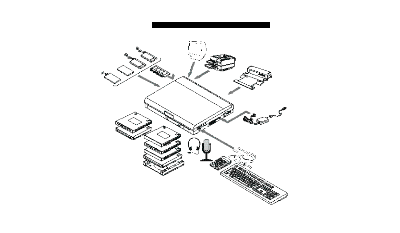
A LifeBook 200 Series notebook is a completely
self-contained unit with a dual-scan (DSTN)
color LCD display. It has a powerful interface
that enables it to support a variety of optional
features.(Figure P-1.)
CONVENTIONS USED IN THE GUIDE
Screen examples in this manual are intended as
examples only,and screen and file names may
differ in actual use.
Messages displayed by the LifeBook 200 Series
appear in Courier type.
Example: Shutdown the computer?
Keyboard keys are shown in boldface
Helvetica type.
Example: Fn, F1,Esc, and Ctrl.
Pages with additional information about a specific topic are cross-referenced within the text.
Example: (See page xx.)
P O I N T
The point icon highlights information
that will enhance your understanding of
the subject material.
C A U T I O N
The caution icon highlights information
that is important to your safety, to the
safe operation of your computer, or to
the integrity of your files. Please read all
caution information carefully.
Page 11
L i f e B o o k 2 0 0 S e r i e s f r o m F u j i t s u
vii
L i f eB o ok 2 00 Se r ie s f rom F u j it s u
Figure P-1 LifeBook 200 Series
with Both Fujitsu and
Third Party Options
Page 12

S e t t i n g U p Yo u r Li f eB oo k 2 0 0 S e r ie s
Unpacking . . . . . . . . . . . . . . . . . . . 2
Overview of LifeBook 200 Series Features . . . 3
Component Identification . . . . . . . . . . . 5
Top and Front Components . . . . . . . . . . 6
Left-side Panel Components . . . . . . . . . . 7
Right-side Panel Components . . . . . . . . . 8
Rear Panel Components . . . . . . . . . . . . 9
Bottom Components . . . . . . . . . . . . . 10
Power Sources . . . . . . . . . . . . . . . . 11
Data Security . . . . . . . . . . . . . . . . . 12
Starting Your Notebook for the First Time . . 13
User Registration . . . . . . . . . . . . . . . 15
Learning About Your Operating System
and Application Software. . . . . . . . . . 15
S e c t i o n O n e
Page 13

S e c t i o n O n e
2
Section One
SETTING UP YOUR LIFEBOOK
200 SERIES FROM FUJITSU
This section describes how to set up your
LifeBook 200 Series from Fujitsu. We strongly
recommend that you read it before using your
notebook – even if you are already familiar with
notebook computers.
UNPACKING
When you receive your notebook,unpack it
carefully,and compare the parts you have
received with the items listed below.
For a standard configuration you should have:
■
LifeBook 200 Series notebook from Fujitsu.
(Figure 1-1.)
■
AC adapter with AC power cord (located in
the Accessories box).(Figure 1-2.)
■
Modular Lithium ion battery.(Already
installed in Multi-function Bay 1 of
your notebook.)
■
Modular 20-speed maximum CD-ROM
drive.(Already installed in Multi-function
Bay 2 of your notebook.)
■
Modular 100Mb Iomega Zip removable
media drive (located in the Accessories box).
(Figure 1-3.)
■
BayAdapter for Multi-function Bay 2
(located in the Accessories box).(Figure 1-4.)
■
Modular 3.5" floppy disk drive (located in the
Accessories box). (Figure 1-5.)
■
RJ-11 cable (located in the Accessories box).
■
Getting Started Guide.
■
User’s Guide.
■
Microsoft Windows Manual.
■
Registration card and customer
information pack.
■
Recovery CD-ROM
(located in the Accessories box).
■
Additional equipment and/
or documentation.
Figure 1-1 LifeBook 200 Series Notebook
Figure 1-2 AC Adapter Unit
Page 14

3
Once you have checked and confirmed that
your notebook system is complete, connect the
AC adapter and follow the instructions on
pages 12-14 to accept the conditions for using
the LifeBook 200 Series notebook.When you
have completed the Conditions of Use process
please register your notebook. (See page 14.)
OVERVIEW OF LIFEBOOK
200 SERIES FEATURES
The LifeBook 200 Series is a compact, yet
powerful notebook computer available with
standard features including: (See Appendix A,
pages 150–163, for detailed information on
individual models.)
■
200MHz or 233MHz Intel Pentium processor
with MMX technology.
■
32MB SDRAM standard, expandable
to 96MB.
■
12.1" HPAdual-scan
(DSTN) color display
with 800 x 600 resolution.
■
2MB EDO video RAM.
■
Built-in 2.1GB or 3.2GB hard drive.
■
Dual Multi-function bays which support
the following:
■
3.5" floppy disk drive
( i n clu ded with all model s ) .
■
20-speed maximum CD-ROM drive
(included with all models) (for Bay 2 only).
■
100MB Iom ega Zip drive
( i n clu ded with all model s ) .
■
Optional second 3.2GB hard drive
(for Bay 2 only).
■
Lithium ion battery
(one included with all models).
■
Optional second Lithium ion battery.
■
Internal 56K fax/data/voice modem with
built-in telephony and DSVD support,
upgradable to v.90.
Figure 1-3 Iomega Zip Drive
Figure 1-4 Bay Adapter for Multi-function Bay 2
Figure 1-5 Floppy Disk Drive
S e t t i n g U p Y o u r L i f e B o o k 2 0 0 S e r i e s
L i fe B o ok 2 0 0 S e r ie s fr o m F u j it s u
C A U T I O N
Your internal modem is designed to allow
faster downloads from K56flex compliant
digital sources. Maximum achievable
download transmission rates may not re a c h
56kbps and will vary with line conditions.
Page 15

S e c t i o n O n e
4
C A U T I O N
The internal modem is not intended
for use with Digital PBX systems. Do not
connect the internal modem to a digital
PBX as it may cause serious damage to
the internal modem or your entire notebook. Consult your PBX manufacturer’s
documentation for details. Some hotels
have Digital PBX systems. Be sure to find
out BEFORE you connect your modem.
■
Full audio and video features:
■
16-bit SoundBlaster-compatible
sound chip.
■
3D-Stereo for multiple speaker effect.
■
ZoomedVideo support for full motion
video acceleration.
■
Built-in stereo speakers.
■
Built-in mono microphone.
■
Stereo line in jack.
■
Stereo headphone jack.
■
Microphone jack.
■
Two Type II/one Type III PC Card slots.
■
Fast IrDA (4Mbps) compatible infrared port
for wireless data transfer.
■
Integrated ErgoTrac™ pointing device for
superb cursor control and comfort.
■
External monitor support with simultaneous
display capabilities.
■
Full-size keyboard with three dedicated
Windows 95 keys.
■
Hot swappable PS/2 port for external
components.
■
USB device support.
■
Bridge battery allowing warm-swapping of
Lithium ion batteries.
■
Standard pre-installed software:
■
Microsoft Windows 95 operating system.
■
LapLink for file transfers via modem, cable
or infrared port.
■
Microsoft Works for business applications
including word processing, spreadsheets
and databases.
■
Quicken Basic 98 for money management.
■
PC-Doctor for system diagnostics.
■
Phoenix PowerPanel for system power
management.
■
SoftPEG from CompCore,an MPEG-1
video player.
■
McAfee VirusScan for virus protection.
■
ESS AudioRack for 3D-Stereo,audio CD
and other audio controls.
■
Iomega Tools software for managing and
using the Zip drive.
■
MegaPhone for telephone applications
including fax,dialing, and speakerphone.
■
Standard user install software:
■
JFax Personnel Telecom®.
■
Internet Explorer®.
■
AOL Free Trial.
■
AT&T WorldNet™.
■
Netscape®Communicator.
Page 16

S e t t i n g U p Y o u r L i f e B o o k 2 0 0 S e r i e s
5
Figure 1-6 LifeBook 200 Series with Display Open
L i fe B o ok 2 0 0 S e r ie s fr o m F u j it s u
COMPONENT IDENTIFICATION
For detailed specifications on each model refer
to Appendix A on pages 150–163.
Status Indicator Panel
Keyboard
ErgoTrac Pointing Device
Multi-function Bay 1
Multi-function Bay 2
Display Panel Latch
Display Panel
Brightness Control
Contrast Control
Built-in Microphone
Suspend/Resume button
Closed Cover Switch
Page 17

S e c t i o n O n e
6
TOP AND FRONT COMPONENTS
Display Panel Latch
This latch locks and releases the display panel.
When the display panel is released it pops up
slightly to make it easier to open.(Figure 1-6.)
Display Panel
This is a color LCD panel with back lighting for
the display of text and graphics. (Figure 1-6.)
Brightness Control
The brightness control adjusts the overall
intensity of the display panel back lighting.
(Figure 1-6.)
Contrast Control
The contrast control (located just below the
brightness control) sets the ratio of the intensity of the light to dark areas of the display.
(Figure 1-6.)
Built-in Microphone
The built-in microphone allows mono audio
input to your notebook. (Figure 1-6.)
Status Indicator Panel
An LCD display of the status of the power state
and source, Suspend mode,battery charge (battery in either Multi-function Bay), floppy disk
drive activity,hard drive or Zip drive activity,
CD-ROM drive activity, PC Card activity,
CapsLock, NumLk and Scr Lk. (Figure 1-6.)
Suspend/Resume Button
The Suspend/Resume button allows you to suspend notebook activity without turning off the
notebook power,and to return it to an active
state. This feature saves power,and is particularly useful when the notebook is running only
on battery power.(See pages 38-46 and 81-87 for
more information on power management.)
(Figure 1-6.)
C A U T I O N
Be sure you know which settings are
active for your Suspend/Resume button
before you use it because misuse can
result in data loss. (See the Power
Savings Menu of the BIOS setup utility,
pages 81-87, for more information.)
Closed Cover Switch
The closed cover switch turns off the LCD
back lighting when the display panel is closed,
thus saving power.This switch also behaves
as a Suspend/Resume button. To change the
functionality of this switch, adjust the settings
in the Advanced Features submenu of the
Power menu in the BIOS Setup Utility.
(See pages 93-100.) (Figure 1-6.)
Page 18

7
Keyboard
A full-size keyboard with dedicatedWindows
95 keys for input into the notebook.
(Figure 1-6.)
ErgoTrac Pointing Device
The integrated ErgoTrac pointing device is
composed of a short, comfortable,dish-shaped
finger mouse and two buttons.Its button-like
shape is both responsive and comfortable for
your finger when rocked gently.(Figure 1-6.)
Multi-function Bay One
This bay accommodates:
■
Lithium ion battery.
■
3.5" floppy disk drive.
■
100MB Zip removable media drive.
Multi-function Bay Two
This bay accommodates:
■
20-speed maximum CD-ROM drive.
■
100MB Zip removable media drive
mounted in the Bay Adapter for
Multi-function Bay 2.
■
Lithium ion battery mounted in the
Bay Adapter for Multi-function Bay 2
(a second battery can be purchased separately
for a dual battery configuration).
■
Optional second 3.2GB hard drive
(which must be purchased separately).
■
3.5" floppy disk drive mounted in the Bay
Adapter for Multi-function Bay 2.
C A U T I O N
Do not use your notebook with either of
the Multi-function bays empty. It may
damage your notebook.
S e t t i n g U p Y o u r L i f e B o o k 2 0 0 S e r i e s
L i fe B o ok 2 0 0 S e r ie s fr o m F u j it s u
LEFT-SIDE PANEL COMPONENTS
PC Card Slots
The PC Card Slots allow you to install two Type
I or Type II PC Cards or one Type III PC Card.
(See pages 103-105 for more information on PC
Cards.) The button to the left of the card slots
locks the card(s) in place,and the buttons
to the right of the slots eject the card(s) from
the slots. (Figure 1-7.)
Left Speaker
The built-in dual speakers output
stereo sound from the notebook.
(Figure 1-7 and Figure 1-8.)
PC Card Eject Buttons
Left SpeakerPC Card SlotsPC Card Lock
Figure 1-7 LifeBook 200 Series Left-side Panel
Page 19

S e c t i o n O n e
8
Stereo Line In Jack
The stereo line in jack allows you to connect an
external audio source to your notebook,like an
audio cassette player.This jack will not support
an external microphone. (Figure 1-8.)
Headphone Jack
You can connect headphones or powered
external speakers to the headphone jack.
(Figure 1-8.)
Volume Control
The volume control is a knob which provides
manual control of the sound level of all audio
output from your notebook. (Figure 1-8.)
C A U T I O N
There are also software volume controls.
The knob setting and the software settings
will interact. Be sure to check both the
software volume control and the knob on
your notebook if you are experiencing
problems. (See Volume Control on page
34 for more information.)
RIGHT-SIDE PANEL COMPONENTS
Theft Prevention Lock Slot
This is a slot that allows you to attach a physical
lock down device. (Figure 1-8.)
USB Port
This port allows you to connect Universal
Serial Bus devices,such as external game pads,
pointing devices, keyboards and speakers.
(Figure 1-8.)
DC Power Jack
The DC power jack allows you to plug in the
AC adapter or the optional auto/airline adapter.
(Figure 1-8.)
Power Switch
This switch is the main power switch for your
notebook. (Figure 1-8.)
Right Speaker
The built-in dual speakers output stereo sound
from the notebook. (Figure 1-7 and Figure 1-8.)
External Floppy Disk Drive Port
A port for attaching an optional external floppy
disk drive. This allows you to connect an
optional separate floppy disk drive when the
Multi-function bays are being used for other
purposes. (Figure 1-8.)
PS/2 Port
The port allows you to connect an external PS/2
keyboard,mouse, or numeric keypad.
(Figure 1-8.)
Microphone Jack
The microphone jack allows you to connect an
external mono microphone. (Figure 1-8.)
Stereo Line
In Jack
Headphone Jack
Volume
Control
PS/2
Port Cover
Port
Microphone
Jack
Figure 1-8 LifeBook 200 Series Right-side Panel
External Floppy
Disk Drive Port
Right Speaker
Power Switch
DC Power Jack
Theft Prevention
Lock Slot
USB
Port
Page 20

S e t t i n g U p Y o u r L i f e B o o k 2 0 0 S e r i e s
9
C A U T I O N
The internal modem is not intended for
use with Digital PBX systems. Do not
connect the internal modem to a digital
PBX as it may cause serious damage to
the internal modem or your entire note-
book. Consult your PBX manufacturer’s
documentation for details. Some hotels
have Digital PBX systems. Be sure to find
out BEFORE you connect your modem.
L i fe B o ok 2 0 0 S e r ie s fr o m F u j it s u
REAR PANEL COMPONENTS
RJ-11 Jack
This is the jack for attaching a telephone line to
the internal modem. This jack can be used with
the connector cover closed and the sliding
panel in the connector cover slightly opened
for added convenience.(Figure 1-9.)
RJ-11 Jack
Docking Port
Serial Port
Parallel Port
External
Monitor Port
Slide Panel
Connector Cover
Infrared Port
Figure 1-9 LifeBook 200 Series Rear Panel
Docking Port
This port is for connection to an optional port
replicator or docking station. The connector
cover must be closed and the sliding panel fully
opened to reveal the docking port and the
RJ-11 jack when connecting a port replicator
or a docking station. (Figure 1-9.)
C A U T I O N
The cover – which closes over the ports
on the rear of the notebook – can be
damaged if it is left open when the
notebook is moved around.
Serial Port
The serial port allows you to connect serial
RS-232C devices, such as serial printers or
serial scanners. (This is also sometimes
referred to as a COM port.) (Figure 1-9.)
Page 21

S e c t i o n O n e
10
Main Unit and Configuration Label
This label shows the model number and other
information about your notebook. In addition
the configuration portion of the label has the
serial number and manufacturer information
that you will need to give your support representative so that he or she can help you. It identifies the exact version of various components
of your notebook.(Figure 1-10.)
Memory Upgrade Compartment
This compartment houses the memory upgrade
module which allows you to expand the system
memory capacity of your notebook. (See pages
108-110 for more information on installing
added memory capacity.) (Figure 1-10.)
Multi-function Bay 1 Release Button
This is the release to allow removal and installation of devices in Multi-function Bay 1.
(Figure 1-10.)
Multi-function Bay 1
This compartment is accessed from the front of
your notebook. (See Figure 1-6 on page 5.)
Parallel Port
The parallel port allows you to connect
parallel devices, such as a parallel printer to
your notebook. (This is also sometimes
referred to as an LPT port.) (Figure 1-9.)
External Monitor Port
This port allows you to connect an external
VGA or SVGA CRT monitor.(Figure 1-9.)
Infrared Port
The fast IrDA (4Mbps) compatible port
allows you to communicate with another IrDA
compatible infrared device without a cable.
(See pages 46-47 for more information.)
(Figure 1-9.)
BOTTOM COMPONENTS
Tilt Adjustment Feet
These are a pair of feet which flip down and
hold the back of the notebook approximately
6° higher than the front when resting on a flat
surface.They are designed to make using your
notebook keyboard more comfortable.
(Figure 1-10.)
Docking Alignment
Receptacle
Memory
Upgrade
Compartment
Multi-function
Bay 2
Multi-function Bay 2
Release Button
Tilt
Adjustment
Feet
Figure 1-10 LifeBook 200 Series Bottom
Docking Alignment
Main Unit
and
Configuration
Label
Multi-function
Bay 1
Multi-function Bay 1
Release Button
Receptacle
Page 22

11
Multi-function Bay 2 Release Button
This is the release to allow removal and installation of devices in Multi-function Bay 2.
(Figure 1-10.)
Multi-function Bay 2
This compartment is accessed from the front of
your notebook. (See Figure 1-6 on page 5.)
POWER SOURCES
Your notebook has four possible power sources:
the primary Lithium ion battery; an optional
dual Lithium ion battery configuration; the AC
adapter; or an optional auto/airline adapter.
Connecting the Power Adapters
The AC adapter or an optional auto/airline
adapter provides power for operating your
notebook and charging the batteries.
(Figure 1-11.)
To Connect the AC Adapter
1. Plug the DC Output cable of the AC
adapter into the DC Power jack on the
right side panel of your notebook.
2. Plug the AC adapter into an AC
electrical outlet.
To Connect the Optional Auto/airline Adapter
1. Plug the DC Output cable into the DC
Power jack on the right side panel of
your notebook.
S e t t i n g U p Y o u r L i f e B o o k 2 0 0 S e r i e s
Figure 1-11 Connecting the AC Adapter
L i fe B o ok 2 0 0 S e r ie s fr o m F u j it s u
2. Plug the auto/airline adapter plug into the
cigarette lighter of a car or other vehicle
with the ignition key in the On or the
Accessories position or into the DC
Power jack on an airplane seat.
To Switch From AC Adapter Power
To Battery Power
1. Be sure that you have at least one charged
battery installed.
2. Remove the AC or auto/airline adapter.
Page 23

S e c t i o n O n e
12
C A U T I O N
Make sure you memorize your password s ,
both hard w a re and software. If you
f o rget, you may not be able to use the
notebook, and you will have to contact
your service provider and arrange to
have them reset the hard w a re system
p a s s w o rd. See your software documentation for what to do if you forget your
s o f t w a re security password ( s ) .
C A U T I O N
The primary Lithium ion battery is not
charged when you purchase your notebook. Initially you will need to connect
the AC adapter or the auto/airline adapter
to use it. If you purchase a second Lithium
ion battery it will not be charged when
you get it. You will need to charge it prior
to use. It can take up to three (3) hours to
charge a single battery if your notebook
is turned off or is in Suspend mode. If
your notebook is in use it can take up
to nine (9) hours or more to charge a
single battery.
DATA SECURITY
Your LifeBook 200 Series has a built-in hardware control password security feature that
allows you to protect the data stored in the
notebook from unauthorized access. Your
operating system and some applications have
software control password security features that
allow you to protect all or portions of the data
stored in the notebook from unauthorized access.
Hardware Data Security Features
When you are using your notebook built-in
hardware control password to gain access to the
notebook the actual password will not appear
on the screen. This is a safety precaution. The
hardware control security parameters are set
from the BIOS setup utility. (See Security Menu
on pages 77-80 for more information on setting
and clearing passwords and enabling and
disabling built-in security features.)
Software Data Security Features
The operating system and some applications
have security features that are independent of
the built-in hardware protection features that
are controlled from the BIOS. See your software
documentation for more information about
these features.
C A U T I O N
Software security feature passwords may
not be the same as the hardware security
passwords. Be sure you know which
features are controlled from software
and which from hardware or you may
lock yourself out of your own data or
lock up your hardware and not be able
to operate your notebook.
Page 24

S e t t i n g U p Y o u r L i f e B o o k 2 0 0 S e r i e s
13
STARTING YOUR NOTEBOOK
FOR THE FIRST TIME
Booting the System
The first time that you turn on your notebook
you will need to attach your AC adapter
because the battery is not charged when you
get your machine. We strongly recommend
that you not attach any other external devices
and do not put any CDs or floppy disks in your
drives until you have gone through the initial
power on sequence.
When you turn on your notebook for the first
time it will display a Fujitsu logo on the screen.
If you do nothing the system will read the hard
drive for the operating system software, flash
the notebook configuration information on the
screen,and then the Windows 95 Setup Wizard
Screen will appear.(See Power On on pages 23-
24 for additional help.) You will then be stepped
through the condition of use process.You must
complete this initial process before you will be
able to use your notebook. (If you wish to
access the BIOS setup utility before you go
through the condition of use process you must
press the F2 key while the Fujitsu logo is still
visible. If you press the Esc key while the
Fujitsu logo is still present you will get a dialog
box which will allow you to select which drive
is to be used for finding the operating system.)
If you turn off the power without using the on
screen Cancel button you will get an error
message when you start your notebook again.
Conditions of Use Process
The first time you start your notebook you
must confirm your acceptance of the copyright
limitations for your pre-installed software.
After you complete the Condition of Use
process these screens will not appear again.
There are 6 screens to read carefully and
respond to.
You cannot use your notebook until this
Condition of Use process is completed. The
bottom of each screen has a <Back button, a
Next> button and a Cancel button which
are activated by the integrated ErgoTrac cursor
control and button click.The <Back button
will return you to the previous screen. The
Next> button activates any choices or
information you have entered and takes you on
to the next screen. The Cancel button allows
you to stop the setup process.
If you stop the process your notebook will
start up at the beginning of the Windows 95
Setup Wizard.
The screens you will be required to respond
to are described with the required action.
User Information
Fill in your name and your company name as
you want the software licensed. To step from the
name blank to the company blank press the Tab
key.When the information has been entered
click on the Next> button.You will not be
allowed to continue until you make an entry.
License Agreement
Read the agreement carefully.You can scroll
through the text using the integrated ErgoTrac
pointing device to activate the scroll bar or use
the up arrow Õ and down arrowÔ keys to
move up and down the text one line at a time,
L i fe B o ok 2 0 0 S e r ie s fr o m F u j it s u
Page 25

S e c t i o n O n e
14
Windows 95 Setup
Once you have completed the printer setup or
chosen not to set up a printer at this time, you
will see the Windows 95 setup screen. This
screen lets you set up Internet Explorer 4.01
with Active Desktop on your Lifebook.
Follow the on-screen directions to complete
installation of Internet Explorer 4.01.
P O I N T
If you would like to skip the installation
of Internet Explorer 4.01, go to the Start
Menu on the desktop, select Shutdown
and restart the computer. After returning
to Windows you can install Internet
Explorer 4.01 anytime by selecting the
icon, setup for Internet Explorer 4.0, in
the Internet Starts Here folder on the
desktop or in the Internet Software
folder in the start menu.
or use the Page Up and Page Down keys to
move the text one screen at a time. When you
finish reading you must point and click to
accept or reject the terms of the agreement and
then click on the Next> button.
P O I N T
If you reject the terms of the license
agreement you will be asked to review
the license agreement for information on
returning Windows 95 or to shut down
your notebook.
Certificate of Authenticity
Look in the box that your notebook came in
and you will find a Windows 95 Certificate of
Authenticity shrink wrapped with the Windows
95 Users manual.On the certificate you will
find a bar-code with a number above it. This is
your product code and the number you should
enter on the Certificate of Authenticity screen.
When you have entered the number exactly as
shown then click on the Next> button.
Start Wizard
The Start Wizard screen will appear if you have
entered a valid product code. When you click
on the Finish button the display will flash various screens as the system identifies what hardware is installed and runs a virus check.
Time Zone
When your notebook has completely identified
all of the installed hardware it will display a
dialog box for entering which time zone you
wish to set the clock to.
Windows Messaging
Once you have selected a time zone you will see
a screen announcing that Windows messaging
is being set up.
Printer Setup
When the messaging setup is complete a dialog
box will appear for selecting which printer is to
be attached to your notebook.You do not have
to select a printer at this time. If you do not
wish to select a printer,click on the Cancel
button.If you do wish to select a printer click
on the Next button and answer the questions.
Page 26

S e t t i n g U p Y o u r L i f e B o o k 2 0 0 S e r i e s
15
REGISTERING YOUR LIFEBOOK
What are the benefits of registering?
You will receive an identification label for your
LifeBook, which,if your LifeBook is ever lost,
may help in getting it returned to you. You also
receive priority Personal Identification Number
(PIN) technical support access and useful product mailings. Proof ofpurchase is not required
if you register within 30 days of your purchase.
P O I N T
You will find a Recovery CD-ROM packet
in your accessories box. Please store the
packet in a safe place in case there is a
loss of data and it becomes necessary to
re-install your operating system and/
or application programs. (See Restoring
Your Pre-installed Software from the
R e c o v e ry CD-ROM on page 141.)
L i fe B o ok 2 0 0 S e r ie s fr o m F u j it s u
How do I register?
By modem, fax,mail or telephone.To register
your system by modem, with your system up
and running, click on the FujitsuWelcome
Center Icon.Complete the electronic form and
click on the “send registration”button. Your
registration information will be transmitted via
phone lines to the Fujitsu Registration Center
and you will receive registration confirmation
in one week to 10 days. You may also print your
completed registration form and fax it to
1-714-450-9140 or mail it to:
Fujitsu PC Corporation
15355 Barranca Pkwy, Irvine,CA 92618-9520
Alternately you may call:
1-800-8fujitsu (1-800-838-5487)
LEARNING ABOUT YOUR OPERAT I N G
SYSTEM AND APPLICATION SOFTWA R E
Tutorials
All operating systems and most application
software have tutorials built-in.We highly
recommend that you step through your
tutorial before you use an application even if
you are familiar with the same application on
a different machine, an earlier version of the
application, or a similar product.
Manuals
In the accessories box you will find manuals for
Windows 95 and other pre-installed software.
Software manuals of pre-installed software
that are not in the accessories box are available
online. See the help screens of your preinstalled software. We recommend that you
review these manuals for general information
on the use of these applications and to get
a basic understanding of what is covered in
the manual,and how it is organized,should
questions arise as you use the applications.
Page 27

Using Your LifeBook 200 Series from Fujitsu
Display Panel . . . . . . . . . . . . . . . . . 18
Adjusting the Keyboard Angle . . . . . . . . 19
Status Indicator Panel. . . . . . . . . . . . . 19
Power On . . . . . . . . . . . . . . . . . . 23
Power Off . . . . . . . . . . . . . . . . . . 24
Restarting the System . . . . . . . . . . . . 25
Fujitsu Welcome Center . . . . . . . . . . . 26
Batteries . . . . . . . . . . . . . . . . . . . 26
Integrated ErgoTrac Pointing Device . . . . . 30
Using the Keyboard. . . . . . . . . . . . . . 32
Volume Control. . . . . . . . . . . . . . . . 34
Floppy Disk Drive . . . . . . . . . . . . . . . 34
CD-ROM Drive. . . . . . . . . . . . . . . . 36
Iomega Zip Drive . . . . . . . . . . . . . . . 38
Hard Drive . . . . . . . . . . . . . . . . . . 39
Power Management . . . . . . . . . . . . . 40
Internal Modem . . . . . . . . . . . . . . . 48
Infrared Port . . . . . . . . . . . . . . . . . 48
Pre-installed Software . . . . . . . . . . . . 49
S e c t i o n T w o
Page 28

S e c t i o n T w o
18
SECTION TWO
USING YOUR LIFEBOOK 200 SERIES
FROM FUJITSU
This section describes the indicators,buttons,
connections and operating modes of your
LifeBook 200 Series and their uses.
DISPLAY PANEL
Opening the Display Panel
Lifting the latch releases the top of the display
panel from the front of the notebook body.
When the display panel is released it pops up
slightly to make it easier to open.Lift the display panel backward until the screen is at a
comfortable viewing angle. (Figure 2-1.)
Adjusting the Display Panel
When you turn on your notebook, you may
want to adjust the brightness level of the screen
for best visibility. To do this, adjust the brightness control slider on the right side of the display panel. (Figure 2-2.) You may need to adjust
the brightness periodically for different
Figure 2-1 Opening the Display Panel
operating environments.You may also adjust
contrast with a contrast control slider that is
just below the brightness control.
P O I N T
The higher the brightness level, the more
power the notebook will consume and
the faster your batteries will discharge.
For maximum battery life, make sure that
the brightness is set as low as possible.
Brightness Control
Brighter
Less Bright
Contrast Control
Figure 2-2 Display Adjustments
Page 29

19
ADJUSTING THE KEYBOARD ANGLE
On the bottom of your notebook,near the
back,are a pair of feet which flip down and
hold the back of the notebook about 6° higher
than the front when resting on a flat surface.
They are designed to make it more comfortable
to use the keyboard with your notebook.The
feet must be folded flat against the bottom
of the notebook when opening or using the
CD-ROM drive or it will not open or operate
properly. (Figure 1-10 on page 9)
C A U T I O N
When you are not using the adjustment
feet be sure that they are folded flat
against the bottom of the notebook.
They could be broken off or injure
someone if not used properly.
C A U T I O N
Do not operate your CD-ROM drive
or attempt to open the tray unless your
notebook is sitting on a flat surface and
the adjustment feet are folded against
the bottom of the notebook. Using a
CD-ROM drive when it is not level
may damage the drive or prevent
proper operation.
U s i n g Y o u r L i f e B o o k 2 0 0 S e r i e s
STATUS INDICATOR PANEL
The Status Indicator panel is located in the
recess just above the keyboard. (Figure 2-3.)
The appropriate indicators become visible as
you use your notebook.
Power Indicator
The Power indicator tells you when the system
is operational. It is on steady when there is
power to your notebook,and blinks when the
system is in Suspend mode. It goes off when
the system has entered Save-to-Disk mode,has
entered the Windows 95 pseudo-off state, or
the power is turned off from the power switch.
L i f eBo ok 2 00 S eri e s f rom Fuj i tsu
P O I N T
When your notebook has been shut
down from Windows 95, it is not the
same as turned off from the power
switch. It is in a pseudo-off state, with
all applications closed, but can be turned
on by pressing the Suspend/Resume
button. It is drawing some current in
the pseudo-off state.
C A U T I O N
Your notebook’s power switch must be
turned off to prevent all current draw.
Page 30

S e c t i o n T w o
20
AC Adapter Indicator
The AC Adapter indicator tells you whether the
system is operating on an AC or auto/airline
adapter,or batteries alone. The indicator is On
when either of the adapters is active and Off
when power comes from the batteries alone. If a
battery is charging,the Power Adapter indicator
is active regardless of the setting of the power
switch. The AC Adapter indicator is also active
in the Windows 95 pseudo-off state,regardless
of the battery status. If there is no battery
charging, and the power switch is Off,then the
ACAdapter indicator and the Battery indicators
will all be Off.
Battery Indicators
The two sets of battery indicators show whether
or not the primary Lithium ion battery and/or
the optional second Lithium ion battery are
installed,and indicate the condition of each.
(Figure 2-3.) Battery 1 is the Lithium ion battery which is installed in Multi-function Bay 1
and Battery 2 is the Lithium ion battery which
is installed in Multi-function Bay 2. The battery
indicators are displayed only for a battery which
is installed.
Figure 2-3 Status Indicator Panel
Power Battery
Identifier
AC Adapter Battery
Charging
Level
CD-ROM
Drive Access
Hard Drive and
Zip Drive Access
Floppy Disk
Drive Access
PC Card
Slot Identifier
PC Card Access
NumLk
CapsLock
Scr LkBattery
Page 31

21
A small arrow icon (Battery Charging indicator) appears to the left of each of the Battery
Level indicators and above the number (Battery
identifier) if that battery is charging.The
Battery Charging indicator flashes if the battery
is too hot or too cold to charge. (Figure 2-3.)
The Battery Charging indicators operate
whether the power switch is Off or On.
The symbols inside the battery outline of the
Battery Level indicator show the operating level
available in that battery. (Figure 2-4.) If there is
no battery charging and the power switch is Off
then the AC Adapter indicator and the Battery
indicators will all be off.
C A U T I O N
Turning off the power with the power
switch or using the Suspend/Resume
button when any of the Access indicators
are On may cause loss of data and/or
system errors.
C A U T I O N
A shorted battery is damaged and must
be replaced. (See Figure 2-4.)
U s i n g Y o u r L i f e B o o k 2 0 0 S e r i e s
C A U T I O N
Batteries subjected to shocks, vibration
temperatures or extreme temperatures
can be permanently damaged.
CD-ROM Drive Access Indicator
The CD-ROM Access indicator tells you
the CD-ROM drive is being accessed.The
CD-ROM Access indicator will flash when
the software tries to access a CD or CD-ROM
even if no CD-ROM drive is installed.
L i f eBo ok 2 00 S eri e s f rom Fuj i tsu
76%–100%
51%–75%
26%–50%
13%–25%
Low Warning ≤12%
Dead Battery
Shorted Battery
Figure 2-4 Battery Level Indicator
Page 32

S e c t i o n T w o
22
P O I N T
The Windows 95 CD automatic insertion
function will periodically check for a
CD installed in the drive, causing the
CD-ROM Access indicator to flash. The
CD automatic insertion function allows
your system to automatically start a CD
as soon as it is inserted in the drive and
the tray is closed. It will begin playing
an audio CD or will start an application
if the CD has an auto run file on it.
P O I N T
If you do not wish to have the CD
automatic insertion function on you
can disable it.
To disable the CD automatic insertion function
do as follows:
1. Save all data and close all applications.
2. Click on the Start button.
3. Point to S e t t i n g s .
4. Click on the Control Panel.The control
panel window will be displayed.
5. Double click on the System icon. The system
properties dialogue box will be displayed.
6. Click on the Device Manager tab. The device
list will be displayed.
7. Click on the + to the left of the CD-ROM
icon. The CD-ROM drive manufacturer’s
name and model will be displayed.
8. Click on the CD-ROM drive manufacturer’s
name and model.
9. Click on Properties.The CD-ROM drive
manufacturer’s name and model properties
dialogue box will be displayed.
10. Click on the Settings tab.
11. Click on the automatic insertion notification box to toggle it off.
12. Click on O K.
13. Click on OK in the system properties
dialogue box.
14. Restart your notebook according to the
message displayed.
You can re - en a ble the functi on by repe a ting the
process except in step 11 ch a n ge the set ting to on .
Hard Drive and Zip Drive Access Indicator
The Hard Drive Access indicator tells you when
the internal hard drive,the Zip drive, or the
optional second hard drive is being accessed.
P O I N T
The Hard Drive Access indicator does not
show which hard drive or Zip drive is
being accessed. It works the same for
both hard drives and Zip drives.
Page 33

U s i n g Y o u r L i f e B o o k 2 0 0 S e r i e s
23
Floppy Disk Drive Access Indicator
The Floppy Disk Drive Access indicator tells
you a floppy disk drive is being accessed. The
Floppy Disk Drive Access indicator will flash
when your software tries to access a floppy disk
even if no floppy disk drive is installed.
PC Card Access Indicators
The PC Card Access indicators tell you when
an installed PC Card is being accessed.Card 1
is the bottom connector inside the slot and
Card 2 is the upper connector inside the card
slot. Type III cards are always Card 1 only.
The PC Card Access indicator will flash if
your software tries to access a PC Card even
if none are installed.
NumLk Indicator
The NumLk indicator tells you the internal keyboa rd is set in ten - key nu m eric keyp ad mode .
(See pa ge 33 for more info rm a tion on the nu m eri c
keypa d . ) You can activa te the NumLk mode by
pressing the NumLk/Scr Lkkey while holding
down the S h i f tkey.De activa te the mode the
same way that you activa ted it.
CapsLock Indicator
The CapsLock indicator tells you when the keyboard is set for all capital letters.Activate the all
capital letters setting by pressing the CapsLock
key on the keyboard. Deactivate the mode the
same way that you activated it.
Scr Lk Indicator
The Scr Lk indicator tells you when scroll lock
is active.You can activate or deactivate the
scroll lock by pressing the NumLk/Scr Lk key.
Deactivate the mode the same way that you
activated it.
POWER ON
Facing the keyboa rd and display panel ,m ove the
power swi tch tow a rds the rear of your noteboo k .
This is the On po s i ti on .(See Fi g u re 2-5.)Wh en
you are done working you can leave your notebook in Su s pend mode ( see pa ges 43 and 84),
or you can tu rn it of f . The power swi tch moved
tow a rd the front of your notebook is in the Off
po s i ti on . (See the se ction Power Of f , pa ges 24-25,
for the re co m m en d ed shutof f pro cedu re s . )
Figure 2-5 Power Switch
L i f eBo ok 2 00 S eri e s f rom Fuj i tsu
On
Off
Page 34

S e c t i o n T w o
24
C A U T I O N
After turning off your notebook, make
sure that it has been Off at least 10
seconds before turning the power switch
to On. If you do not you could cause a
system error. When you turn on your
notebook be sure you have a power
source. This means that at least one
battery is installed and charged, or that
the AC adapter or the auto/airline
adapter is connected and has power.
C A U T I O N
Do not carry your notebook around
with the power on or subject it to shocks
or vibration, as you risk damaging
your notebook.
C A U T I O N
The main Lithium ion battery is not
charged when you purchase your notebook. Initially you will need to connect
the AC adapter to use it. If you purchase
an optional second Lithium ion battery, it
will not be charged when you get it, you
will need to charge it prior to use.
When the power switch is turned on, your
notebook carries out a Power On Self Test
(POST) to check the internal parts and configuration. If a fault is found a beep will sound
and/or an error message will be displayed.
(See Troubleshooting on pages 138-140) Depending on the nature of the problem you may be
able to continue by starting the operating
system or by entering the setup utility and
revising the settings.
Af ter sati s f actory com p l eti on of the Power On
Sel f Test (POST) your notebook wi ll load yo u r
opera ting sys tem .(See Boot Menu on pa ges 88-
89 to see wh i ch kind of disk wi ll be the sou rce.)
C A U T I O N
Never turn off your notebook during
Power On Self Test (POST) or it will
cause an error message to be displayed
when you turn your notebook on the
next time. (See the Troubleshooting
information on pages 138-140.)
POWER OFF
Before turning off the power by putting the
power switch in the Off position, check that the
Hard Drive/Zip Drive,CD-ROM,PC Card and
the Floppy Disk Drive Access indicators are all
Off. (See Figure 2-3, page 20.) If you turn off the
power while accessing a disk or PC Card there
is a risk of loss of data.The Off position is
reached by facing the keyboard and display
panel,and moving the switch toward the front
of your notebook.To assure that your notebook
shuts down without error,use the Windows 95
shut down procedure.
Page 35

U s i n g Y o u r L i f e B o o k 2 0 0 S e r i e s
25
If you are going to store your notebook for a
month or more,take the following precautions:
1. Remove any CD and/or floppy disk.
2. After shutting down with Windows 95 turn
off your notebook using the power switch.
3. Close your notebook display panel.
4. Disconnect the AC adapter.
5. Remove the batteries and store them
separately in a cool dry place.
RESTARTING THE SYSTEM
When you wish to restart your system be sure
that you follow the proper procedure. The
procedure is as follows:
1.Go to the Start button menu.
2. Click on S h u t D o w n .
3. Click on Restart the computer?
4. Verify that Restart the computer? is
selected and click on Y e s .
Windows 95 will shutdown and restart
your notebook.
NOTE:You may also select Shut down the com-
puter? and once the power is off for 10 seconds
or more you can restart your notebook with the
Suspend/Resume button.You may also select
Shut down the computer? and once the power
is off turn the power switch to Off for 10
seconds or more and then turn the power
switch to On. These alternative methods
are not recommended.
C A U T I O N
Never turn your notebook off while an
application is running. Be sure to close all
files, exit all applications and shut down
your operating system prior to turning off
the power with the power switch. If fil e s
a re open when you turn the power off ,
you will lose any changes that have not
been saved, and may cause disk erro r s .
L i f eBo ok 2 00 S eri e s f rom Fuj i tsu
Shutting down your notebook from Windows
95 lets your notebook shut down operations,
and turn off the power in the proper sequence
to prevent errors. The sequence is:
1.Go to the Start button menu.
2. Click on S h u t D o w n .
3. Verify that
Shut down the computer?
is selected and click on Y e s .
P O I N T
When your notebook has been shut
down from Windows 95, it is not the
same as being turned off from the power
switch. It is in a pseudo-off state, with all
applications closed, but can and must be
turned on by pressing the Suspend/
Resume button. It is drawing some
current in the pseudo-off state.
Page 36

S e c t i o n T w o
26
P O I N T
In Windows 95 pressing the Ctrl+Alt+Del
keys simultaneously triggers the
ShutDown submenu of the Start menu.
C A U T I O N
Turning off the power switch without
exiting Windows 95 may cause an error
when you start the next time. Turning
the power to On when it has been Off
for less than 10 seconds may also cause
an error when you start the next time.
FUJITSU WELCOME CENTER
The Fu j i t su Wel come Cen ter is an icon on
your Wi n dows 95 de s k top.Cl i cking on it give s
you access to produ ct regi s tra ti on forms and
i n s tru cti on s ,ch a n ge of ad d ress inform a ti on and
form s ,con t act inform a ti on including tel eph on e
nu m bers and e-mail ad d re s s e s ,and an acce s s ory
c a t a l og with the inform a ti on for ordering acce ss ories for your noteboo k . Do u ble lef t - cl i ck on
the icon and then on the appropri a te but ton for
the inform a ti on sel ecti on you wi s h .
BATTERIES
The Lithium ion batteries are rech a r ge a ble wi t h
an opera ting time of up to three (3) hours
depending on active power managem ent fe atu res and user activi ty level s .Your notebook can
be opera ted on the pri m a ry Lithium ion battery
a l one or in a dual battery con fig u ra ti on with an
opti onal second Lithium ion battery.A bu i l t - i n
bri d ge battery all ows a ch a r ged Lithium ion
b a t tery to be exch a n ged for a disch a r ged on e
by “ w a rm - s w a pp i n g”. To warm - s w a p, h ave a
ch a r ged battery re ady,p ut your notebook in
Su s pend mode ,rem ove the low battery and
qu i ck ly insert a ch a r ged battery.( For more
i n fo rm a tion on wa rm - s wa pping see pa ge 122.)
The Lithium ion battery operating time may
become shorter than the reference value if it is
used under the following conditions:
■
When used at temperatures that exceed a low
of 5°C or a high of 35°C.High temperatures
not on ly redu ce ch a r ging ef f i c i en c y , but
can also cause battery deteri ora ti on . (Th e
Ch a r ging icon on the Status In d i c a tor panel
wi ll flash wh en you try to ch a r ge a battery that
is out s i de its opera ting tem pera tu re ra n ge . )
■
The battery ch a r ging capac i ty is redu ced as the
b a t tery age s .If your battery is running low
qu i ck ly,you should rep l ace it with a new on e .
■
When using a high current device such as a
modem, a LAN card,the CD-ROM drive, or
the hard drive frequently.
Using the AC adapter will conserve your battery
when using a high current device such as a
modem, a LAN card,the CD-ROM drive, or the
hard drive frequently.
Page 37

U s i n g Y o u r L i f e B o o k 2 0 0 S e r i e s
27
C A U T I O N
Actual battery life will vary based
on screen brightness, applications,
features, power management settings,
battery condition, and other customer
preferences. CD-ROM drive, hard drive,
and Zip Drive usage may also have a
significant impact on battery life.
L i f eBo ok 2 00 S eri e s f rom Fuj i tsu
C A U T I O N
Do not leave a faulty battery in your
notebook. It might damage your AC
adapter, optional auto/airline adapter,
another battery, or your notebook itself.
It may also prevent operation of your
notebook by draining all available current
into the bad battery.
C A U T I O N
Under federal, state or local law it
may be illegal to dispose of batteries by
putting them in the trash. Please take
care of our environment and dispose
of batteries properly. Check with your
local government authority for details
regarding recycling or disposing of
old batteries. If you cannot find this
information elsewhere, contact your
support representative at 1-800-8FUJITSU
(1-800-838-5487).
Bridge Battery
The bridge battery is a NiCd battery that is
built-in your notebook and is constantly being
recharged.A bridge battery allows a charged
Lithium ion battery to be exchanged for a discharged one by “warm-swapping”.
To warm-swap,have a charged battery ready,
put your notebook in Suspend mode,remove
the low battery and quickly insert a charged
battery.The bridge battery capacity is not large,
about 3 minutes,and can vary with the
condition of your notebook.
C A U T I O N
Data may be lost and/or system
errors introduced if the warm-swap is
not performed quickly or a power
adapter installed.
C A U T I O N
The bridge battery can not support an
active notebook. The notebook must be
in Suspend mode.
Page 38

S e c t i o n T w o
28
Shorted Batteries
If your Status Indicator panel shows a shorted
battery,check the installation for that battery by
removing and re-installing it. If it still shows
that it is shorted, replace it with a new battery.
The Lithium ion batteries are recharged internally using the AC adapter or auto/airline
adapter.To recharge the batteries:
■
Make sure the battery to be charged is
installed in either Multi-function bay of
your notebook and connect the AC or
auto/airline adapter.
■
Make sure that the Battery Charging indicator to the left of the Battery Level indicator
of the battery to be charged is visible on the
Status Indicator panel.
■
Make sure the percentage charge is shown
inside the Battery Level icon.
(Figure 2-4 on page 21.)
When two Lithium ion batteries are installed,
the charge/discharge rate of the primary and
optional second Lithium ion batteries are the
same,as they are connected in parallel and are
both charging and/or discharging at the same
time. Since the rates are the same, one may finish charging or discharging before the other if
they were not at the same charge level when they
were installed and/or the AC or auto/airline
adapter was connected.
There is no memory effect on the Lithium ion
batteries, which means that you do not need to
discharge them completely before recharging. A
single fully discharged Lithium ion battery will
charge in approximately three (3) hours when
your notebook is Off or in Suspend mode. The
charging time from fully discharged for two
Lithium ion batteries together, is approximately 5
hours when your notebook is Off or in Suspend
mode.Of course partially charged batteries will
not take as long to charge. The charge times will
be significantly longer if your notebook is in use
while the batteries are charging (from approximately nine (9) hours for one battery to approximately 15 hours for two batteries with normal
operating levels).
C A U T I O N
A shorted battery is damaged and must
be replaced so that it does not damage
anything else.
Recharging the Batteries
If you want to ch eck the con d i ti on of ei t h er the
pri m a ry Lithium ion battery or an opti onal second Lithium ion battery,ch eck the Ba t tery Level
i n d i c a tors loc a ted on the Status In d i c a tor panel .
These indicators ch a n ge as the battery level s
ch a n ge .Ba t tery 1 is a Lithium ion battery wh i ch
is install ed in Mu l ti - f u n cti on Bay 1 and Ba t tery
2 is a Lithium ion battery wh i ch is install ed in
Mu l ti - f u n cti on Bay 2. ( Fi g u re 2-3 on pa ge 20.)
You can also ch eck the Power Pa n el too l b a r.
C A U T I O N
Using heavy current devices such as LAN
cards or frequent CD-ROM accesses may
prevent charging completely.
Page 39

U s i n g Y o u r L i f e B o o k 2 0 0 S e r i e s
29
Low Battery State
When the battery is running low,your notebook beeps about every 15 seconds and the
Battery Level indicator(s) flash. If you do not
respond to the low battery alarm,the batteries
will continue to discharge until they are too low
to operate.When this happens there will be a
multiple beep alarm,the Battery Level indicator
will show dead battery,and your notebook will
go into Suspend mode to try and protect your
data as long as possible. Your power management settings do not affect what happens at the
dead battery alarm level.Your notebook will go
to Suspend mode. (Figure 2-3 on page 20.)
When the low battery alarm occurs you need to
save all your active data and put your notebook
into Suspend mode until you can provide a new
power source.You should provide this power as
soon as possible. The new power source can be
a charged battery or a power adapter,either AC
or auto/airline.
Battery Suspend mode shows on the Status
indicator just like the normal Suspend mode.
Once you have provided power,you will need
to press the Suspend/Resume button to resume
operation. In the Suspend mode,your data can
be maintained for sometime. If a power source
is not provided promptly,the Power indicator
will stop flashing and go out,and you will have
lost the data that was not stored.
Once you provide power you can continue to use
your notebook while an adapter is charging the
battery,but the battery trickle charges under
these conditions. If you want to charge the
battery more quickly,put your notebook into
Suspend mode, or turn off your notebook while
the adapter is charging the battery.(See Power
Offon pages 24-25 for shutdown procedures.)
C A U T I O N
You may not be able to hear the audio
alarms if the volume control is set too
low or is turned off by either hardware or
software but you will still be able to see
the Battery Level indicator(s) flash.
L i f eBo ok 2 00 S eri e s f rom Fuj i tsu
C A U T I O N
When you are in Suspend mode there
must always be at least one power sourc e
active. If you turn off the power with
the power switch, or remove all power
s o u rces, battery, AC adapter or auto/
airline adapter, while your notebook is in
Suspend mode any data which has not
been saved to the hard drive will be lost.
Once your notebook goes into Dead Battery
Suspend mode you will be unable to resume
operation until you provide a source of power
either from an AC adapter,an optional auto/
airline adapter,or a charged battery.Dead
C A U T I O N
There is no guarantee that data will not
be lost once your notebook enters the
Dead Battery Suspend mode.
Page 40
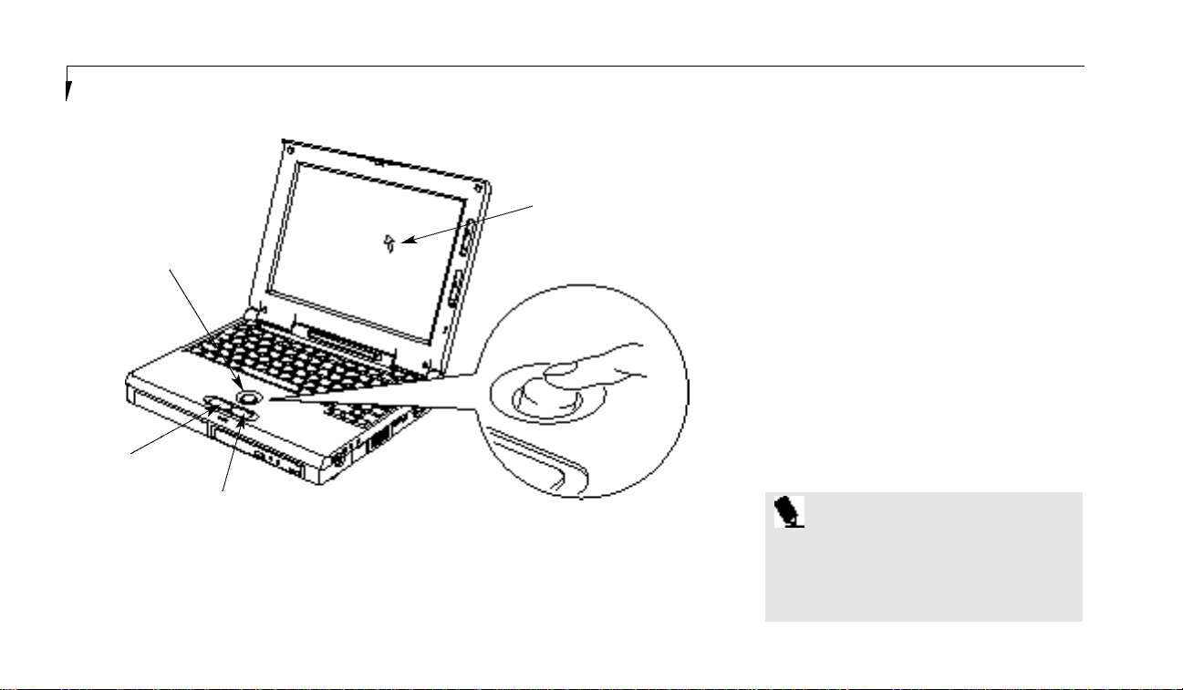
S e c t i o n T w o
30
INTEGRATED ERGOTRAC
POINTING DEVICE
The ErgoTrac pointing device is composed of
a short, comfortable,dish-shaped pointing
device and two buttons located in front of the
keyboard. The ErgoTrac pointing device has
the function of a mouse,and moves the cursor
around on the screen – up, down, left and right.
A light pressure with the tip of your finger is all
that is required to operate the ErgoTrac. The
more pressure you use the faster the cursor will
move. The second part of the ErgoTrac pointing
device – the buttons – function as mouse buttons,and the functions they perform depend on
the application you are running. Figure 2-6
shows the position of the ErgoTrac pointing
device and buttons.
Figure 2-6 ErgoTrac pointing device
Cursor Control
Left Button
Right Button
Cursor
P O I N T
An external mouse can be connected to
the PS/2 port on the right side of the
notebook, and used simultaneously with
the ErgoTrac pointing device.
Page 41

31
Clicking
Clicking means pushing and releasing a button.
To left-click move the screen cursor to the item
you wish to select, press the left pointing device
button once,and then immediately release it. To
right-click,move the mouse cursor to the item
you wish to select, press the right pointing
device button once,and then immediately
release it. (Figure 2-7.)
Double-Clicking
Double-clicking means following the preceding
Clicking procedure,but pressing the pointing
device button twice in rapid succession.
Double-clicking works with both the left
and right buttons.
Dragging
Dragging means selecting an item with the
pointing cursor,and while keeping the left
pointing device button depressed, moving the
cursor to the desired new location, then releasing the button. (Figure 2-8.)
Figure 2-7 Clicking
Left Click Left Double Click
U s i n g Y o u r L i f e B o o k 2 0 0 S e r i e s
C A U T I O N
If the interval between clicks is too long,
double-clicking will not be executed.
P O I N T
The interval between presses for double
clicking, and other parameters of pointing
and selecting, can be adjusted with the
selections in the dialog box of the mouse
icon in your Windows Control panel.
L i f eBo ok 2 00 S eri e s f rom Fuj i tsu
Figure 2-8 Dragging
ErgoTrac Pointing Device
Control Adjustment
The Windows Control Panel provides cus-
tomization of your ErgoTrac pointing device
from the mouse icon. There are four (4) aspects
of the ErgoTrac pointing device operation
which you can adjust.
■
Buttons – This lets you set up the buttons for
right or left handed operation and set the
time interval for double clicking.
Page 42

S e c t i o n T w o
32
■
Pointers – This lets you set up the size and
shape of the cursor for different functions.
■
Motion – This lets you set up the relation of
the speed of motion of your finger to the
motion of the cursor and to enable a trailing
tail for the cursor arrow.
■
General – This allows you to choose the type
of mouse being used. It is already set for your
integrated ErgoTrac.You may need to change
it for an external mouse.
You may want to try practicing with different
adjustments until you find a combination that
is comfortable for you.
USING THE KEYBOARD
Your notebook has an integral 86-key keyboard.
(Figure 2-9.) The keys perform all the standard
functions of a 101-key keyboard and also
include Windows 95 keys and other special
function keys. This section describes only those
items specific to your notebook. They are the
numeric keypad,the cursor keys,the function
keys, the function extension key (Fn) and the
Windows 95 keys.
Figure 2-9 Keyboard
Function Keys Numeric Keypad
Fn Key Start Key Start Key Application Key Cursor Keys
Page 43

U s i n g Y o u r L i f e B o o k 2 0 0 S e r i e s
33
Numeric Keypad
Certain keys on the keyboard perform dual
functions as both standard character keys and
numeric keypad keys.Figure 2-9 highlights
these keys. To switch into numeric keypad
mode,press the NumLk/Scr Lk while holding
down the Shift key.You can now enter numerals
0 through 9, perform addition ( + ),subtraction
( – ),multiplication ( * ),or division ( / ),and
enter decimal points ( . ) using the keys designated as ten-key function keys. The keys in the
numeric keypad are marked on the front edge
of the key to indicate their secondary functions.
To return these keys to their normal character
function, press the NumLk/Scr Lk while holding
down the Shift key again.
P O I N T
When an external numeric keypad is connected to the notebook the NumLk mode
enables the external keypad and disables
the built-in keyboard numeric keypad.
L i f eBo ok 2 00 S eri e s f rom Fuj i tsu
Cursor Keys
The cursor keys are the four arrow keys on the
keyboard which allow you to move the cursor
up Õ, down Ô,left Ó and right È as your
application allows.
P O I N T
The integrated ErgoTrac pointing device
and/or external mouse are also used for
moving the cursor around the screen.
Function Keys
Your notebook has 12 function keys,F1 through
F12. The functions assigned to these keys differ
for each application. You should refer to your
software documentation to find out how these
keys are used. (See Figure 2-9.)
Fn Key
The Fn key provides extended functions for the
notebook and is always used in conjunction
with another key.(See Figure 2-9.)
Pressing F5 while holding down the Fn key
allows you to toggle between video compensation and no compensation. (Video compensation controls spacing on the display.When it is
enabled,displays with less than 800 x 600 pixel
resolution will still cover the entire screen.)
Pressing F 1 0while holding down the F n key
a ll ows you to ch a n ge your sel ecti on of wh ere to
s end your display vi deo. E ach time you press the
com bi n a ti on of keys you wi ll step to the nex t
ch oi ce . The ch oi ce s , in order,a re : built-in disp l ay panel on ly, ex ternal mon i tor on ly,or bo t h
built-in display panel and ex ternal mon i tor.
Windows 95 Keys
Your notebook has three Windows 95 keys,two
Start keys and an Application key. The Start key
displays the Start menu. This is the same as the
button on the toolbar which is typically at the
bottom of your Windows 95 desktop. The
Application key has the same function in
Windows 95 as the right mouse button,it displays the Shortcut menu for whatever item is
selected. See your Windows 95 documentation
for additional information. (See Figure 2-9.)
Page 44

S e c t i o n T w o
34
VOLUME CONTROL
All system and application functions have multiple volume controls which interact with each
other.There is the hardware volume control on
the right side panel of your notebook.There is
a volume control in the ESS AudioRack, your
operating system Sound Control panel and any
other application with sound.
Each setting source puts an upper limit on the
volume which can be set by the other sources.
For example if the hardware volume control is
turned all the way down, your software volume
control settings have no effect. By the same
token,if the ESS AudioRack has the sound
turned off, adjusting the hardware or other
application software volume settings will not
produce sound.One easy operating method is
to use the hardware and ESS AudioRack volume
controls to set an upper limit on sound level
and then make fine adjustments with other
application software.
C A U T I O N
The ESS AudioRack volume setting
sets the maximum volume level of the
hardware volume control knob.
C A U T I O N
If you use a speakerphone function,
be sure that the microphone setting in
the ESS AudioRack (recorder portion)
is disabled.
FLOPPY DISK DRIVE
The modular floppy disk drive is a 3.5" drive
which can read and write on 1.44MB and
720KB memory capacity floppy disks.Floppy
disk format is controlled from your operating
system.(See your software documentation for
more information.) The modular floppy disk
drive can be used in Multi-function Bay 1,
Multi-function Bay 2 with the Bay Adapter
Multi-function Bay 2, or you can use the optional external floppy disk drive. The system will
treat any floppy disk drive in exactly the
same way regardless of where it is installed.
(For floppy disk drive installation and removal
instructions see Multi-function Bays on pages 97100 and External Installation of a Floppy Disk
Drive on page 107.) When your system boots it
will always look first for a floppy disk drive in a
Multi-function Bay 1, Multi-function Bay 2, and
then look at the external floppy disk drive port.
C A U T I O N
To get your system to recognize a newly
installed floppy disk drive you must
restart your notebook.
Loading a Floppy Disk
To load,insert a floppy disk into the floppy disk
drive,shutter side first and label up,until the
Eject button,above the floppy disk drive opening, pops out. (Figure 2-10)
for
Page 45

U s i n g Y o u r L i f e B o o k 2 0 0 S e r i e s
35
Ejecting a Floppy Disk
To eject a disk, check that the Floppy Disk
Drive Access indicator is Off, (see pages 20
and 23) and press the Eject button.
(Figure 2-10.)
To prevent data stored on a floppy disk from
being erased,slide the write protect tab on the
floppy disk to open up the small hole. This
makes the disk write protected. When you want
to write data to that disk,slide the write protect
tab the other way to close the small hole.
Figure 2-10 Loading/Ejecting a Floppy Disk
C A U T I O N
If you eject the disk while the Floppy
Disk Drive Access indicator is On, there is
a risk of damaging the data on the disk
or the disk drive.
L i f eBo ok 2 00 S eri e s f rom Fuj i tsu
Write Enabled
P O I N T
When there is no floppy disk in the drive,
the Eject button is flush with the front of
your notebook.
Preparing a Floppy Disk for Use
Before you can use a new floppy disk,you need
to prepare it so your notebook knows where to
store information. This preparation is called
formatting or initializing a disk. You need to
format new 3.5" floppy disks, unless you purchase preformatted disks. You will use your
notebook’s operating system software to format
a floppy disk.Please refer to the operating sys-
tem manual for step-by-step instructions.
Write Protected
Figure 2-11 Floppy Disk Write Protect
Page 46

S e c t i o n T w o
36
C A U T I O N
Formatting a previously used floppy
disk is an effective method of clearing a
disk as long as you realize that ALL the
information on the disk will be erased.
Care of Floppy Disk Drives and Disks
■
Avoid storing the floppy disk drive and
disks in extremely hot and cold locations,
or in locations subject to severe
temperature changes.
■
Keep the floppy disk drive and disks
out of direct sunlight and away from
heating equipment.
■
Avoid storing the floppy disk drive in
locations subject to shock and vibration.
■
Avoid using the floppy disk drive and disks
in damp and dusty locations.
■
Never use the floppy disk drive with any
liquid,metal, or other foreign matter inside
the floppy disk drive or disk.
■
Never store a floppy disk near a magnet or
magnetic field.
■
To clean,wipe the floppy disk drive clean
with a dry soft cloth or with a soft cloth
dampened with water or a solution of neutral
detergent.Never use benzene,paint thinner,
or other volatile material.
■
Never disassemble or dismantle your floppy
disk drive.
CD-ROM DRIVE
The modular CD-ROM drive is a 20-speed
maximum modular reader.
C A U T I O N
Do not operate your CD-ROM drive
unless your notebook is sitting on a
flat surface and the adjustment feet
are folded against the bottom of the
notebook. Using a CD when the drive
is not level may damage the drive or
prevent proper operation.
Figure 2-12 Loading the CD-ROM Tray
Page 47

37
Loading a CD
■
Make sure that the angle adjustment feet on
the bottom of the notebook are folded
against the bottom of the notebook.
■
Make sure there is power to your notebook.
■
Push, gently but firmly,and release the eject
button on the front of the CD-ROM drive to
open the CD-ROM holder tray,the tray will
come out a short distance.
■
Gently pull the tray out until a CD-ROM can
be easily placed in the tray.
■
If there was a protective sheet in the tray
when it was shipped,make sure it
has been removed.
■
Place the CD into the tray, label side up, with
the hole in the center of the CD snapped
onto the raised circle in the center of the tray.
■
Close the tray.
■
After the CD is loaded,it will take a short
time for your notebook to recognize it.
P O I N T
If you have disabled your CD automatic
insertion function you will have to start
the CD from your desktop, as your
notebook will not automatically
recognize that the CD has been loaded.
U s i n g Y o u r L i f e B o o k 2 0 0 S e r i e s
Figure 2-13 CD-ROM Handling
Care of CD-ROMs
CD-ROMs are precision devices and will function reliably if given reasonable care.
■
Always store your CD-ROM in its case when
it is not in use.
L i f eBo ok 2 00 S eri e s f rom Fuj i tsu
■
When removing the CD-ROM from its case,
press down on the holder’s center while lifting out the CD-ROM by its edges.
■
Always handle a CD-ROM by the edges and
avoid touching the surface.
■
Avoid storing any CD-ROM in extreme
temperatures.
■
Do not bend CD-ROMs or set heavy objects
on them.
■
Never write on the label surface with a ball
point pen, pencil or similar device.
■
If a CD-ROM is subjected to a sudden
change in temperature, cold to warm condensation may form on the surface.Wipe the
moisture off with a clean,soft,lint free cloth
and let it dry at room temperature. DO NOT
use a hair dryer or heater to dry a CD-ROM.
■
If a CD-ROM is dirty,use only a CD-ROM
cleaner or wipe it with a clean,soft, lint free
cloth starting from the inner edge and wiping
to the outer edge.
Page 48
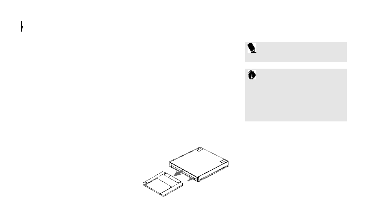
S e c t i o n T w o
38
IOMEGA ZIP DRIVE
The 100MB Iom ega Zi pd rive is a modu l a r
rem ova ble media drive de s i gn ed for use in ei t h er
Mu l ti - f u n cti on bay of your Life Book 200 Seri e s
n o teboo k .The Zi p tools sof t w a re (pre - i n s t a ll ed
on your notebook) all ows easier managem ent of
i n form a ti on on Zip disks and the functi on a l i ty of
Zip disks and drives with the opera ting sys tem .
The Zip drive has an automatic sleep mode
designed to reduce power consumption and
prolong the life of the battery in your notebook.
Sleep mode automatically spins down a disk
after a set period of inactivity; the disk automatically spins up again when accessed.
Inserting and removing Zip disks
To insert a disk in the Zip drive:
■
Orient the disk with the label side up, and the
sliding metal access door of the disk toward
the drive.
■
Insert the disk gently into the drive until it
clicks in, and engages in the drive.
■
The green busy light will flash momentarily
and then go out.(If the light continues to
blink slowly,push the disk eject button to
eject the Zip disk, then reinsert it.)
■
To remove a Zip disk, press the gray button
on the front of the drive, or click on the Zip
100 icon in the My Computer window with
the right mouse button and select eject.
■
When you remove a Zip disk from the drive,
store it in the protective case.
■
The Zip drive will automatically eject the disk
when you shut down your LifeBook 200
Series notebook.
■
Store all your Zip disks in the protective case
when not in use.
C A U T I O N
When using the disk eject button, push
gently. Do not use force! The green busy
light blinks as the disk “spins down” and
the drive takes a few seconds to eject the
Zip disk. Never force a disk into or out of
the Zip drive.
Figure 2-14 Ejecting the Iomega Zip disk
P O I N T
Zip Disks must be purchased separately
Emergency Disk Eject
Your LifeBook 200 Series notebook must be
powered on for normal disk ejection from the
Zip drive. Never use force to remove a disk
from the Zip drive. If you must remove a Zip
disk from the drive when power is not available,
carefully push a straightened paper clip into the
emergency eject hole located on the eject button. Use care when using this method as exces-
sive force or a bent paper clip may cause damage to your Zip drive.
Page 49

39
■
Write protect a Zip disk and assign a password that must be used to remove the
write protect.
■
Read Protect a Zip disk so that it cannot be
read from, or written to, unless the user
enters the password you assign.
For information on using read/write protect,
refer to the Zip Tools help file.
HARD DRIVE
The internal hard drive capacity is dependent
on which model you are using.See Appendix
A (pages 150–163) for model information. If
you are using the optional second hard drive for
the first time since you installed it, you can get
your notebook to recognize it by opening the
Windows 95 Control Panel and opening Add
New Hardware which will step you through
the process of having Windows look for your
newly installed device.
Formatting the Hard Drive
The hard drive inside your notebook is form a tted (initi a l i zed) at the factory.You do not need
to format it under normal circ u m s t a n ce s .If yo u
C A U T I O N
Use the emergency disk eject procedure
only when the laptop is without power.
Do not try to forcibly remove a Zip disk
from the drive. If the disk does not eject
immediately, repeat the emergency disk
eject procedure as described above.
Zip Disk Tips
■
Never force a Zip disk into or out
of the drive.
■
It is a good idea to return the Zip disk to
its case when it is not in use.
■
Avoid exposing Zip disks to direct
sunlight, high temperature,moisture,
and magnetic fields.
Read/Write Protecting Zip Disks
Your Zip Tools software includes a special
read/write protect feature that lets you:
■
Write protect a Zip disk through special
software instead of with a mechanical write
protect switch.
U s i n g Y o u r L i f e B o o k 2 0 0 S e r i e s
L i f eBo ok 2 00 S eri e s f rom Fuj i tsu
p u rchase an opti onal second hard drive you wi ll
n eed to format it before you use it the first ti m e .
Ch eck your opera ting sys tem doc u m en t a ti on for
i n form a ti on on initializing a hard drive .
C A U T I O N
If you reformat the internal hard drive
ALL data including the operating system,
applications software and data will be
erased. Unless data is copied to floppy
disks or other data storage media it will
be permanently lost. All software will be
need to be re-installed and data files
restored from your back-up disks. See
the operating system manual for more
information on backing-up your data
files. The factory installed software,
including the operating system, can be
restored from the Recovery CD-ROM
which came in the accessories box when
you purchased your notebook. (See
Restoring Your Pre-installed Software
from CD-ROM on page 141 for more
information.) Any application software
which you have purchased and installed
Page 50
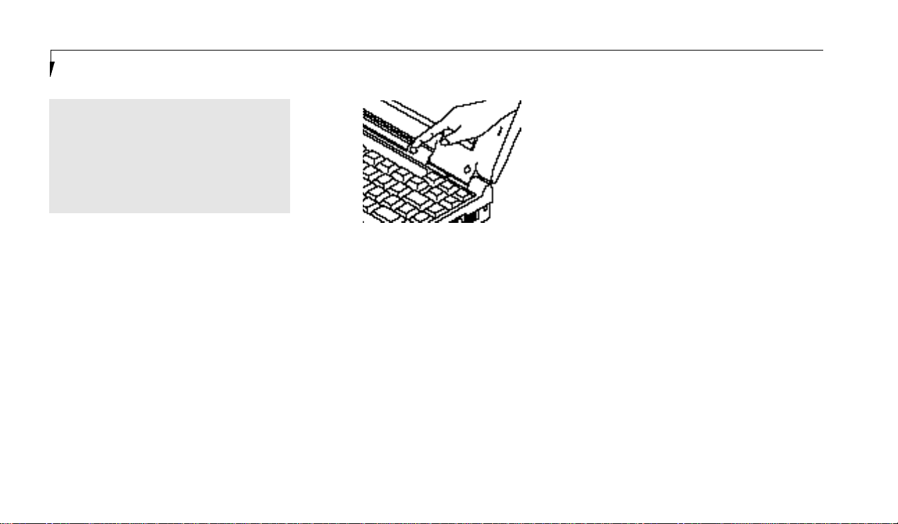
S e c t i o n T w o
40
POWER MANAGEMENT
Your LifeBook 200 Series has many features for
conserving power.Some power savings features
are automatic and have no user control,such
as those for the internal modem, while others
depend on the parameters you set to best suit
your operating conditions. Other power saving
features turn the display brightness down, limit
the use of high power devices, activate an
appropriate power savings profile,and put your
notebook in Suspend mode when not actually
performing an operation.As with all mobile,
battery-powered computers,there is a trade-off
between performance and power savings.
Internal power management for your notebook is controlled from settings made in the
BIOS setup utility, PowerPanel by Phoenix
Technologies,and the Windows 95 Control
panel. If no settings have been made in the
PowerPanel orWindows 95 Control panel then
the BIOS settings will be used. The PowerPanel
and Windows 95 Control panel have been
pre-set at the factory and will be active unless
you disable them. Complete descriptions of
the BIOS setup utility parameters are found in
Section Three of this guide. Power management
parameters are covered under the Power
Savings menu. (See pages 81-87.)
Some particular power parameters are only
available for setup from one of these places,
others can be changed in any one of them.
Using the Suspend/Resume Button
When your notebook is active,the Suspend/
Resume button (Figure 1-7 on page 7) can
be used to manually put your notebook into
Suspend mode, or into the Save-to-Disk mode.
Push the Suspend/Resume button,when your
notebook is active but no Access indicators are
on,and hold it in until it is acknowledged by
activation of the selected mode. Which mode
is activated is determined by the settings of the
BIOS setup utility Power Savings menu. The
default is Suspend mode. (See page 84 for how
to select Save-to-Disk mode.)
If your notebook is suspended,pushing the
Suspend/Resume button will return your notebook to active operation at the point where it
went into suspension. The Suspend/Resume
button is located next to the Status Indicator
panel above the keyboard of your notebook.
(Figure 2-14) You can tell whether or not your
Figure 2-15 Suspend/Resume Button
will have to be re-installed from the
original source. When doing a recovery
remember that you must allocate space
for the Save-to-Disk function if you have
it enabled. (See Setting Up Your Save-to-
Disk File Allocation on pages 93-94 for
more information.)
Page 51

U s i n g Y o u r L i f e B o o k 2 0 0 S e r i e s
41
P O I N T
Disabling the Suspend/Resume button
prevents it from being used to put your
notebook in Suspend or Save-to-Disk
mode. The resume function of the button
cannot be disabled. (See the Power
Savings Menu of the BIOS setup utility,
pages 81-87, for more information.)
L i f eBo ok 2 00 S eri e s f rom Fuj i tsu
system is in Suspend mode by looking at the
Power indicator.(See pages 19-20.) If it is visible
and not flashing, your notebook is fully operational. If it is visible and flashing,your notebook is in Suspend mode.If it is not visible,
the power is Off, the power is in the Windows
95 pseudo-off state,or your notebook is in
Save-to-Disk mode.(See pages 44-45.) When
you receive your LifeBook 200 Series it will be
set to the default, which is Suspend mode.
C A U T I O N
Be sure you know which settings are
active for the Suspend/Resume button
before you use it; misuse can result in
data loss. (See the Power Savings Menu
of the BIOS setup utility, pages 81-87,
for more information.)
P O I N T
If your notebook is active when you
enter the Suspend or Save-to-Disk mode,
changes to open files are not lost. The
files are left open and memory is kept
active during Suspend mode or the
memory is transferred to the internal
hard drive during Save-to-Disk mode.
C A U T I O N
The Suspend or Save-to-Disk mode
should not be used with certain PC Cards.
Check your PC Card documentation for
more information.
C A U T I O N
If you are running your notebook on
battery power, be aware that the battery
continues to discharge while your notebook is in suspend mode, though not as
fast as when fully operational. With a
fully charged internal Lithium ion battery
the suspend mode will maintain your
status for 24 hours or more.
PowerPanel
PowerPanel by Phoenix Technologies provides
Windows 95 desktop access to a comprehensive
combination of power management settings
without entering the BIOS setup utility.
Page 52

S e c t i o n T w o
42
The PowerPanel icon looks like an atom with
its cloud of electrons. This icon will open the
PowerPanel menu.You can view the menu in
icon format along the edge of your desktop by
moving the cursor against the edge where you
have chosen to keep your PowerPanel toolbar
and letting it sit there until the toolbar appears.
(The default position for the toolbar is the left
side of the screen,but you can move it to
whichever edge you like by dragging.)
The power management toolbar has ten power
profile choices and six activation choices.
When you switch to AC powered operation the
PowerPanel toolbar will automatically change to
indicate AC power operation and will show the
AC Power profile as active.
The profiles are groups of system settings
designed to fit power operation to specific user
operating conditions. The activations are shortcut ways to turn on specific power management
features of your notebook.Some of the profiles
can be edited and saved from the PowerPanel
application, some can be edited and saved from
the BIOS setup utility and only viewed from
PowerPanel,and some are factory set and can
only be viewed from either PowerPanel or the
BIOS setup utility.
The profile choices are:
(This group is factory set.)
■
Maximum Battery Life.
■
Maximum Performance.
■
Power Management Off.
(This one is set only from the
BIOS setup utility.)
■
Custom Settings.
(This group is set from PowerPanel.)
■
Presentation.
■
Green PC.
■
AC Profile.
■
Word Processing.
■
Communication.
■
Games.
The activation choices are:
■
System Suspend.
■
System Save-to-Disk.
■
System Standby.
■
Hard Disk Standby.
■
Modem Power Toggle.
■
Video Standby.
The factory set Maximum Power Savings profile
is designed around trade offs of performance
and battery life. For truly maximum battery life
keep the display and volume levels as low as
possible and use the custom settings recommended in Section Three on page 100.
P O I N T
The AC Power profile is activated automatically when a power adapter is being
used, unless it is overridden by another
selection made after the adapter became
active. It can be reactivated by selecting
it or it can be activated by selection, even
when operating only on battery power.
Page 53

U s i n g Y o u r L i f e B o o k 2 0 0 S e r i e s
43
POWERPANEL ONLINE HELP
To access help with your power management
settings, move your cursor to the PowerPanel
toolbar and right click. (See Clicking on
page 33.) From the menu that appears select
PowerPanel Help Topics.
POWERPANEL CUSTOMIZATION
To modify your PowerPanel toolbar or create
a custom toolbar,move your cursor to the
PowerPanel toolbar and right click. From the
menu that appears select Customize. Within the
Customize dialog box you can choose to have
the toolbar display at all times or to use your
custom toolbar.You can also select from the
same menu to Hide the toolbar. If you hide the
toolbar you will have to double click on the
edge where the toolbar was located to display it.
If you select Exit from the PowerPanel menu
you will turn off the PowerPanel completely. To
turn it back on,go to the Program folder of the
Start menu,select PowerPanel and click on it.
MAXIMUM BATTERY LIFE PROFILE
The Maximum Battery Life profile is a factory
installed combination of timeouts and other
power savings parameters read directly from
the BIOS,and chosen as the settings that will
produce the longest possible battery life.
MAXIMUM PERFORMANCE PROFILE
The Maximum Performance profile is a factory
installed combination of timeouts and other
power savings parameters
read directly from
the BIOS and
chosen as the settings that will
produce superior performance with reasonable
battery life.
POWER MANAGEMENT OFF
Turns off power management control from
Windows 95 and PowerPanel and turns it over
directly to the BIOS.
CUSTOM SETTINGS PROFILE
The Custom Settings profile has those power
saving parameters that you set in the BIOS
setup utility using the Power Savings Menu
Customize feature.(See Power Savings on
pages 86-93.)
P O I N T
The Maximum Power Savings, Maximum
Performance, and Power Management
Off profiles are read only. The Custom
Settings Profile can only be changed
from the BIOS setup Utility.
L i f eBo ok 2 00 S eri e s f rom Fuj i tsu
PRESENTATION PROFILE
The Presentation profile is the same combination of timeouts and other power savings
parameters as the Maximum Battery Life
profile except that the display is never turned
off. (This profile was designed to enhance
the use of your notebook for slide show
style presentations.)
GREEN PC PROFILE
The Green PC profile has the Video timeout
and the Hard Drive timeout enabled but no
standby or suspension modes enabled.
Page 54

S e c t i o n T w o
44
AC PROFILE
The AC power profile has all timeouts disabled
and no other power management features
enabled. This profile is activated automatically
by plugging in a power adapter.
WORD PROCESSING PROFILE
The Word Processing profile is a factory
installed combination of timeouts and other
power savings parameters chosen as the settings
that will produce superior performance with
reasonable battery life when using your notebook for doing word processing.
COMMUNICATION PROFILE
The Communication profile is a factory
installed combination of timeouts and other
power savings parameters chosen as the settings
that will produce superior performance with
reasonable battery life when using your notebook with the modem active such as during
Internet,fax or speakerphone activities.
GAMES PROFILE
The Games profile is a factory installed combination of timeouts and other power savings
parameters chosen as the settings that will produce superior performance with reasonable battery life when playing games on your notebook.
SYSTEM SUSPEND ACTIVATION
Clicking on the Suspend button or selecting
System Suspend on the PowerPanel menu will
put your notebook in Suspend mode.Pressing
the Suspend/Resume button turns the power
back on and lets you begin where you left off.
(See Figure 2-14 on page 42, and Suspend Mode
on pages 47 and 88.)
SYSTEM SAVE-TO-DISK ACTIVATION
Clicking on the Save-to-Disk button or selecting System Save to Disk on the PowerPanel
menu will put your notebook in Save-to-Disk
mode.Your notebook will be left in the
Windows 95 pseudo-off state. If the power
switch is not turned off your notebook can be
restarted by pressing the Suspend/Resume button which will cause the system memory to
reload from the hard drive and let you begin
where you left off. (See Figure 2-14 on page 42,
and Save-to-Disk Mode on pages 47-48.)
SYSTEM STANDBY ACTIVATION
Clicking on the System Standby button or
selecting System Standby on the PowerPanel
menu will put your notebook in Standby mode.
You can return your notebook to normal operation by performing any activity such as pressing
a key or touching the ErgoTrac joystick.
HARD DISK STANDBY ACTIVATION
Clicking on the Hard Disk Standby button or
selecting Hard Disk Standby on the PowerPanel
menu will turn off your internal hard drive.You
can return your notebook to normal operation
by performing any hard drive operation.
MODEM POWER TOGGLE
Clicking on the Modem Power Toggle but-
ton or selecting Modem Power Toggle on the
PowerPanel menu will turn the power to your
modem on or off. To turn it to the other condition select Modem Power Toggle again.
Page 55

U s i n g Y o u r L i f e B o o k 2 0 0 S e r i e s
45
■
Timing out from lack of activity.
■
Battery level reaching the Dead Battery
Warning condition.
Your notebook’s system memory typically stores
the file(s) on which you are working,the open
application(s) and any other data required to
support the operation(s) in progress.When
you resume operation from Suspend mode, it
returns to the point in the operation where it
left off. You must use the Suspend/Resume
button to resume operation,and there must
be an adequate power source available, or
your notebook will not resume.
C A U T I O N
Loss of all power sources, including
batteries, while in the Suspend mode will
cause lost data and inability to re t u rn
to operation with the Suspend/
Resume button.
L i f eBo ok 2 00 S eri e s f rom Fuj i tsu
VIDEO STANDBY ACTIVATION
Clicking on the Video Standby button or selecting Video Standby on the PowerPanel menu
turns off the power to the display.You can
return your notebook to normal operation
by performing any activity such as pressing
a key or touching the ErgoTrac joystick.
Suspend Mode
The Suspend mode saves the contents of your
notebook’s system memory during periods of
inactivity by maintaining power to critical parts
while turning off the CPU, the display,the hard
drive and all of the other internal components
except those necessary to maintain system
memory,recognize the Suspend/ Resume
button and restart. Your notebook can be
put in Suspend mode by:
■
Pressing the Suspend/Resume button
until acknowledged.
■
Selecting Suspend from the Windows 95
Start Menu.
■
Selecting System Suspend from the
PowerPanel toolbar or menu.
Save-to-Disk Mode
The Save-to-Disk function saves the contents
of your notebook’s system memory to the hard
drive whenever you:
■
Press the Suspend/Resume button until
acknowledged with Save-to-Disk mode
enabled from the Power Savings menu of
the BIOS setup utility.
■
Select Suspend from the Windows 95 Start
menu with Save-to-Disk mode enabled by
the BIOS setup utility.
■
Select Save-to-Disk activation from the
PowerPanel toolbar or menu.
■
Time out from lack of activity with Save-ToDisk mode enabled from the Power Savings
menu of the BIOS setup utility.
Your noteboo k’s sys tem mem ory typ i c a lly store s
the file(s) on wh i ch you are work i n g,the open
a pp l i c a ti on(s) and any other data requ i red to
su pport the opera ti on(s) in progre s s .Wh en the
Save - to - Disk functi on is activa ted your noteboo k
s aves the con tents of the sys tem mem ory to a fil e
Page 56

S e c t i o n T w o
46
P O I N T
Save-to-Disk mode requires allocating a
significant amount of hard drive capacity
for saving all system memory, which
reduces your usable disk space. When
you purchase your notebook it will have
space allocated for the memory installed.
If you upgrade the original system by
adding a memory upgrade module
without changing the size of your Saveto-Disk allocation you will get an error
message when you try to activate Saveto-Disk mode and it will not work. Use
the PHDISK Utility to increase the size
of the Save-to-Disk file, SAVE2DSK.BIN.
(Refer to Setting Up Your Save-to-Disk
File Allocation on pages 93-94 for
more information.) If you need help
contact your support representative
for recommendations.
on the internal hard drive ,and then autom a ti c a lly
s huts of f power to your noteboo k . This is the
same pseu do - of f s t a te as the Wi n dows 95 power
of f .Wh en you re sume opera ti on by pressing the
Su s pen d / Re sume but ton ,you retu rn to the poi n t
in the opera ti on wh ere you left of f ,before goi n g
i n to Save - to - Disk mode .
P O I N T
If power is lost during Save-to-Disk mode
the data will be retrieved automatically as
soon as power is re t u rn e d .
P O I N T
When PC Cards or external devices are
in use, Save-to-Disk mode cannot return
to the exact state prior to suspension,
because all of the peripheral devices will
be re-initialized when the system restarts.
P O I N T
The main advantage of using the
Save-to-Disk function is that power is
not re q u i red to maintain your data. This
is particularly important if you will be
leaving your notebook in a suspended
state for a prolonged period of time. The
drawback of using Save-to-Disk mode
is that it lengthens the power down and
power up sequences and resets
peripheral devices.
Page 57

U s i n g Y o u r L i f e B o o k 2 0 0 S e r i e s
47
Idle Mode
Idle mode is one of the power management
parameters.When Idle mode is enabled the
CPU is put into low-speed operation when
there is no activity (keystroke,pointer action,
sound generation, video display change,
modem transmission or reception, etc.) on your
notebook for 16 seconds. Any activity will cause
the normal operation to restart automatically.
This feature is independent of the Suspend/
Resume button.This parameter is enabled
and disabled in the BIOS setup utility.
(See page 83.)
Standby Mode
Standby mode is one of the power management
parameters.When Standby mode is activated,
your notebook puts the CPU in low-speed
operation,shuts off the display and turns off
the hard drive when there is no activity (keystroke,pointer action, sound generation, video
display change,modem transmission or reception, etc.) on your notebook for the user selected time-out period. (See page 83.) Any activity
will cause your notebook to return to normal
Resume button.This parameter is enabled and
disabled in the BIOS setup utility.
Windows 95 Control Panel
The Power icon in the Wi n dows 95 Con tro l
Pa n el all ows you to en a ble or disable all the
power managem ent set ti n gs wh i ch can be made
f rom the de s k top.Sel ecting “All ow Wi n dows to
m a n a ge power use on this com p uter ”a ll ows the
opera ting sys tem to en a ble Phoenix Tech n o l ogi e s
Power Pa n el and Wi n dows 95 Con trol panel
s et ti n gs .Wh en Wi n dows 95 power managem en t
is disabl ed the BIOS setup uti l i ty set ti n gs wi ll
con trol your power saving para m eters .
(See pa ges 81-87 for the BIOS setup uti l i ty
Power Savi n gs menu.)
The Windows 95 Control Panel Power
Management dialog box lets you set different
hard drive timeouts for battery and AC power
operation and to set PC Card modem
power parameters.
operation automatically.This feature is independent of the Suspend/Resume button.This
parameter is enabled and disabled in the BIOS
setup utility.
Video Timeout
The Video Timeout is one of the power management parameters which saves power by
turning off the display if there is no keyboard
or pointer activity for the user selected timeout
period.Any keyboard or pointer activity will
cause the display to restart automatically.This
feature is independent of the Suspend/Resume
button.This parameter is enabled and disabled
in the BIOS setup utility.(See page 82.)
Hard Disk Timeout
The Hard Disk Timeout is one of the power
management parameters which saves power
by turning off the hard drive if there is no hard
drive access for the timeout period which has
been set in the BIOS setup utility.(See page 82.)
Any attempt to access the hard drive will cause
the hard drive to restart automatically. This
feature is independent of the Suspend/
L i f eBo ok 2 00 S eri e s f rom Fuj i tsu
Page 58

S e c t i o n T w o
48
C A U T I O N
Be careful not to scratch the infrared port
lens. Scratches, dirt or other surface
marks can effect operation.
P O I N T
You must restart your notebook for
Windows 95 Control panel setting
changes to take affect.
INTERNAL MODEM
Your internal modem is a fax/data/voice
modem controlled by Windows 95,LapLink,
MegaPhone or other software. The voice functions of the modem include speakerphone and
answering machine capabilities. The answering
machine capabilities require the use of third
party software not included with your notebook. The other features are accessible via
Windows 95,LapLink or MegaPhone. This
modem is upgradeable to the v.90 standard.
INFRARED PORT
Infrared IrDA-compatible communication is
a function that allows for wireless data transfer
between your notebook and other IrDAcompatible devices. Examples of IrDAcompatible devices are another computer
or a printer.When carrying out this kind of
communication,both devices must be set so
their infrared ports are directly facing each
other without obstructions.A distance of 6" to
36" between the device ports is ideal. Dirt or
scratches on the lens of your notebook or the
other device will degrade performance. This is
especially true for Fast IrDA applications such
as a transfer to an Ethernet.Laplink software
can be used for Infrared file transfers.(See the
Laplink online help for more information.)
C A U T I O N
Your internal modem is designed to
allow faster downloads from K56flex
compliant digital sources. Maximum
achievable download transmission rates
may not reach 56kbps and will vary
with line conditions.
C A U T I O N
Do not move either device during
communication as it may interrupt
data transmission.
The following conditions may interfere with
infrared communications:
■
When the infrared communication ports
are not directly facing each other, or some
obstacle is between them.
■
When the infrared communication ports are
too far apart.
■
When a television or radio remote control
unit, or a wireless headphone is being
used nearby.
■
When a strong light such as direct sunlight,
fluorescent light, or incandescent light shines
on the port.
Page 59

U s i n g Y o u r L i f e B o o k 2 0 0 S e r i e s
49
panel is in the equipment rack.When it is off
the dot on the button is black and the control
panel is not in the rack.You activate a slider or
knob on a control panel by dragging it. The
functions available are DAT (Digital Audio Tape
player),3D (3D-Stereo sound control),MIDI,
Mixer and CD (Audio CD player).(Located in
the Multimedia Software folder.)
PRE-INSTALLED SOFTWARE
Your LifeBook 200 Series comes with preinstalled software for playing audio and video
files of various formats. In addition there is file
transfer software, telephony software and virus
protection software. Some models come with
additional application software.
All of the pre-installed software can be accessed
from the Program folder of the Windows 95
Start menu or the following folders above the
Program folder in the Start menu: Business
Software,Communications Software, Multimedia Software, Service and Support Software,
and System Management Software.
SoftPEG MPEG File Player
The MPEG file player displays a screen to find
the file which you wish to play.You can setup
the list to select from limited to particular types
of files or display all files. Opening the desired
file will play it. Online help screens are available
for more information.(Located in the
Multimedia Software folder.)
SoftPEG Video CD Player
This control resembles a VCR player front panel
and is operated in the same way.When you
point to a button,a small explanation of the use
of the button will appear.When you left-click
on the button it will activate. Online help
screens are available for more information.
(Located in the Multimedia Software folder.)
ESS AudioRack
The control of the AudioRack player software
(AudioRack32) resembles the front panels of
a rack of stereo equipment and is operated in
much the same way.There is also AudioRack
recording software (AudioRecorder). Online
help screens are accessible from the AudioDrive
panel of AudioRack32; click on the Help button
for more information. In the AudioRecorder
dialog box,click on Help in the top taskbar.
In AudioRack32 the AudioDrive panel lets you
turn on and off the available functions. When
you left-click on a button it will activate.
When a function is active its button on the
AudioDrive shows a green dot and its control
P O I N T
For maximum frequency response and
bandwidth, leave the graphic equalizer
levels at the mid-point (zero level). To
customize the frequency response to
your personal taste, adjust accordingly.
L i f eBo ok 2 00 S eri e s f rom Fuj i tsu
C A U T I O N
The ESS AudioRack volume settings
sets the maximum volume level of
the hard w a re volume control knob for
that function.
Page 60

S e c t i o n T w o
50
C A U T I O N
If you use a speakerphone function, be
sure that the microphone setting in the
ESS AudioRack is disabled.
LapLink
LapLink by Traveling Sof t w a re provi des direct
file tra n s fers to other com p uters ; data tra n s fers
via internal modem ,a PC Ca rd modem ,t h e
i n f ra red port , a serial cabl e , or a para ll el cabl e
( c a bles are not inclu ded ) .See the LapLink on l i n e
h elp screens for opera ting instru cti on s .( Loc a ted
in the Com mu n i c a ti ons Sof t w a re fo l der. )
MegaPhone
MegaPhone by Cypress Research Corporation is
telephony software which provides access to the
voice and fax features of your notebook’s internal modem. It features dialing, speakerphone
and caller ID, and fax functions.See your
MegaPhone online help screens for guidance
in operating the MegaPhone software. (Located
in the Communications Software folder.)
P O I N T
For optimum speakerphone performance:
■
Speak clearly.
■
Limit background noise.
■
Speak facing the keyboard from about
one (1) foot away.
McAfee VirusScan
Running your McAfee VirusScan program after
loading data or programs from a floppy disk,
CD-ROM,modem data transfer,or infrared
data transfer is a precaution that will protect
the data on your hard drive from contamination or destruction. See your VirusScan online
help screens for information on how and when
to run this program.(Located in the Service
and Support Software folder.)
PC Doctor
PC Doctor by Watergate Software is primarily
for use by your support representative when
helping you with trouble shooting.(See pages
140–141 for more information.) (Located in the
Service and Support Software folder.)
Quicken 98 Basic
Quicken 98 Basic by Intuit is a personal money
management program. It has features such as
portfolio management, account registeries, online banking, and bill paying features.(Located
in the Business Software folder.)
Microsoft Works
Microsoft Works is a suite of software containing
the basic tools to write letters and reports, track
family and friends with the address book,manage home finances, and create a home inventory.
(Located in the Business Software folder.)
P O I N T
If you have an active internet connection
on your notebook you can access our
Service and Support web site by selecting
the icon ‘Fujitsu Service and Support
Web Site’ in the Service and Support
folder in the Start menu.
Page 61

Con f iguri n g You r Lif e Boo k 2 0 0 S e r i es
Boot Sequence . . . . . . . . . . . . . . . . 52
Identifying the Drives . . . . . . . . . . . . . 52
BIOS Setup Utility . . . . . . . . . . . . . . 53
Navigating Through the Setup Utility . . . . . 55
Main Menu – Setting Standard
System Parameters . . . . . . . . . . . . . 56
Advanced Menu – Setting Device
Feature Controls . . . . . . . . . . . . . . 65
Security Menu – Setting the
Security Features . . . . . . . . . . . . . . 87
Power Menu – Setting Power
Management Feature Controls . . . . . . 93
Boot Menu – Selecting the
Operating System Source . . . . . . . . . 101
Info Menu – Displaying Basic
System Information. . . . . . . . . . . . 105
Exit Menu – Leaving the Setup Utility . . . . 107
Setting Up Your Save-To-Disk
File Allocation . . . . . . . . . . . . . . . 110
S e c t i o n T h r e e
Page 62

S e c t i o n T h r e e
52
SECTION THREE
CONFIGURING YOUR LIFEBOOK
200 SERIES FROM FUJITSU
This section explains the BIOS setup utility.
The BIOS setup utility is required to set the
date, time, power management modes,data
security passwords and other operating
parameters of your notebook.
BOOT SEQUENCE
Each time you power up or restart your
LifeBook 200 Series,it goes through a quiet
boot sequence that displays a Fujitsu logo until
your operating system is loaded.During quiet
boot, your notebook is performing a standard
boot sequence including a Power On Self Test
(POST). To access the ability to change the
drive that will be used for finding the operating
system, press the Esc key anytime while the
Fujitsu logo is displayed. To enter the BIOS
setup utility press the F2 key anytime while
the Fujitsu logo is displayed. When the boot
sequence is completed without a failure and
without a request for the setup utility,the
IDENTIFYING THE DRIVES
Your notebook uses drive letters (Example A:,
B:,C:,D:,E:) to identify internal and external
devices such as hard drives, floppy disk drives,
Zip drives, CD-ROM drives and PC Cards.
The most commonly assigned drive designators are listed below.If you add other devices,
the drive designators may be different. See
your operating system manual for setting
drive designations.
Drive Designators
A:Floppy disk drive.
Installable in either of the multi-function
bays of your notebook,or use the external
floppy disk drive.
B: Not used with your notebook.
P O I N T
The BIOS setup utility is entered by
pressing the F2 key during the boot
process while the Fujitsu logo is on
the screen.
system displays the Windows 95 opening
screen.The boot sequence is executed when:
■
You turn on power to the system using the
power switch on the right side panel of your
notebook.(Figure 2-5 on page 23.)
■
You restart your computer from the
Windows 95 Shutdown dialog box of the
Start Menu.
■
The software initiates a system restart.
Example: When you install a new
application.
■
You reset the system by pressing the three
keys Ctrl+Alt+Del at the same time and then
restart your computer from the Windows 95
Shutdown dialog box.
P O I N T
When error messages occur see
Section Five, pages 138-140, for help
in understanding the meaning and
required actions to be taken.
Page 63

53
C A U T I O N
A bootable CD-ROM may have either a
floppy disk format or a hard drive form a t .
When using a bootable CD-ROM, drive
designations will automatically change
a c c o rding to which format is used.
(See page 63 for more inform a t i o n . )
C: Hard drive.
Installed inside your notebook.
D: CD-ROM drive, optional second
hard drive or Zip drive. Installable in
Multi-function Bay 2 of your notebook.
E: Zip Drive if a CD-ROM drive or optional
Second hard drive is installed in Multifunction Bay 2 of your notebook.
BIOS SETUP UTILITY
The BIOS setup utility is a program that sets
the operating environment for your notebook.
It is referred to in this publication as the setup
utility.There is no need to set or change the
C o n f i g u r i n g Y o u r L i f e B o o k 2 0 0 S e r i e s
environment to operate as it is set at the factory
for normal operating conditions.
The setup utility configures:
■
Standard system parameters, such as date
and time.
■
Device control feature parameters, such as
I/O addresses and boot devices.
■
Power Management parameters that help to
conserve your notebook’s batteries.
■
System Data Security feature parameters,
such as passwords.
You will only have to change the utility settings
if you want to:
■
Change the date or time.(You can also
do this without entering the setup utility,
through your operating system. See your
operating system manual.)
■
Change the primary boot device.
■
Change the power management parameter
settings. (For a more convenient process, see
the PowerPanel on pages 40-43.)
L i f eB o ok 2 00 Se r ie s f rom F u j it s u
■
Change a port address or other parameter.
■
Change an audio parameter setting.
■
Change the selection of whether to use the
built-in display,an external monitor or both.
(For a more convenient process, see the Fn key
on page 33.)
■
Change the system data security settings.
Routinely Entering the Setup Utility
You can enter the setup utility whenever you
turn on or reset the system.To do this:
1.Allow the system to start booting.
2.As soon as the Fujitsu logo appears on the
screen, press the F2 key.
3. The Main menu of the setup utility then
appears with the current settings of the
parameters displayed.
4. If you wish to go to one of the other setup
menus, press the Ó or the È key to find the
menu you require.
Page 64

S e c t i o n T h r e e
54
Error message - please run
SETUP program
Press <F1> key to continue, <F2>
to run SETUP
2. If an error message is displayed on the
screen,and you want to continue with the
boot process and start the operating system
anyway,press the F1 key.
P O I N T
If your data security settings require it,
you may be asked for a password before
the operating system will be opened.
P O I N T
If your data security settings require it,
you may be asked for a password before
the Main menu will appear.
Entering the Setup Utility After a
Configuration Change or System Failure
If there has been a change in the system configuration that does not agree with the parameter
settings stored in your BIOS memory,or there
is a failure in the system,the system beeps
and/or displays an error message after the
Power On Self Test (POST).If the failure is not
too severe,it will give you the opportunity to
modify the settings of the setup utility,as
described in the following steps:
1. When you turn on or restart the computer
there is a beep and/or the following message
appears on the screen:
C A U T I O N
If your notebook beeps a series of
beeps that sounds like a code and the
display is blank, please refer to the
Troubleshooting Section. (See page 135.)
The Troubleshooting Section includes
a list of error messages and their
meanings. (See pages 138-140.)
3. If an error message is displayed on the
screen,and you want to enter the setup
utility,press the F2 key.
4 . Wh en the setup uti l i ty starts with a fault pre-
s en t ,the sys tem displays the fo ll owing message :
W a r n i n g !
Error message
[ C o n t i n u e ]
5. Press any key to enter the setup utility.The
system will then display the Main Menu with
current parameters values.
Page 65

C o n f i g u r i n g Y o u r L i f e B o o k 2 0 0 S e r i e s
55
NAVIGATING THROUGH
THE SETUP UTILITY
The BIOS setup utility consists of seven menus;
MAIN,ADVANCED, SECURITY, POWER,
BOOT, INFO and EXIT.The remainder of
Section Three explains each menu in turn
including all submenus and setup items.
The following procedures allow you to navigate
the setup utility menus:
1. To select a menu, use the cursor keys: Ó , È.
2. To select a field within a menu or a submenu,use the cursor keys: Õ, Ô.
3. To select the different values for each field,
press the Spacebar or + to change to the next
higher selection and F5 or - to go to the next
lower selection.
4. To activate a submenu press the Enter key.
P O I N T
Selecting a field causes a help message
about that field to be displayed on the
right-hand side of the screen
L i f eB o ok 2 00 Se r ie s f rom F u j it s u
5. To return to a menu from a submenu,press
the Esc key.
6. To go to the Exit menu from any other
menu, press the Esc key.
P O I N T
Pressing the Enter key with the highlight
on a selection that is not a submenu or
auto selection will cause a list of all
options for that item to be displayed.
Pressing the Enter key or Esc key will
select the highlighted choice and
remove the list.
7.Pressing the F9 key resets all items in the
current menu to the default values.
8. Pressing the F10 key saves the current
configuration and exits the BIOS Setup
Utility.You will be asked to verify this
selection before it is executed.
9. Pressing the F1 key gives you a general
help screen.
P O I N T
The BIOS Setup screens depicted in this
manual are only representations of the
actual setup screens. The BIOS Setup
screens on your notebook may vary.
Page 66
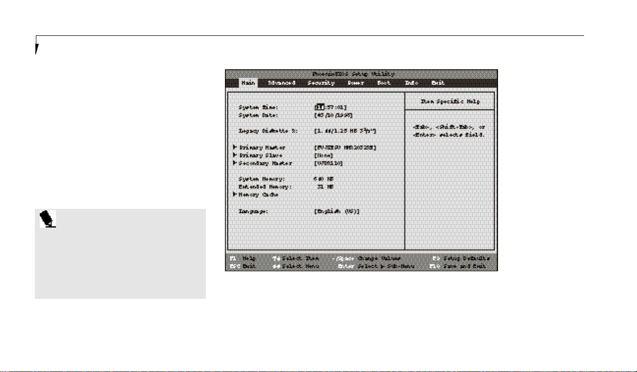
S e c t i o n T h r e e
56
MAIN MENU – SETTING
STANDARD SYSTEM PARAMETERS
The Main Menu allows you to set or view the
current system parameters. Follow the instructions for Navigating Through The Setup Utility
to make any changes. (See page 55.)
Table 3-1 shows the names of the menu fields
for the Main menu,all of the options for each
field,the default settings and a description of
the field’s function and any special information
needed to help understand the field’s use.
P O I N T
System Time and System Date can
also be set from your operating system
without using the setup utility. Use the
calendar and time icon on your Control
panel for Windows 95 or type time or
date from the MS-DOS prompt.
Figure 3-1 Main Menu
Page 67

L i f eB o ok 2 00 Se r ie s f rom F u j it s u
57
Menu Field Options Default Description
System Time: — — Sets and displays the current time.Time is in a 24 hour format
of hours:minutes:seconds with 2 digits for each.(HH:MM:SS).
Example: 16:45:57. You may change each segment of the time
separately.Move between the segments with the Tab key and/or
Shift +Tab keys.
System Date: — — Sets and displays the current date. Date is in a month/day/year
numeric format with 2 digits each for month and day and 4 digits
for year.(MM/DD/YYYY) for example: 03/20/1996. You may
change each segment of the date separately.Move between the
segments with the Tab key and/or Shift +Tabkeys.
Legacy Diskette A: Disabled. 1.44/1.25MB 3.5" Sets the format for floppy disk drive A if it is installed.
Primary Master: Selects Primary Display the type of device on this ATA/ATAPI interface,if there is
Master submenu. one. Pressing the Enter key selects the Primary Master submenu
allowing additional device configuration options for this interface.
Primary Slave: Selects Primary Display the type of device on this ATA/ATAPI interface,if there is
Slave submenu. one. Pressing the Enter key selects the Primary Slave submenu
allowing additional device configuration options for this interface.
Table 3-1 Fields, Options and Defaults for the Main Menu
C o n f i g u r i n g Y o u r L i f e B o o k 2 0 0 S e r i e s
Page 68

S e c t i o n T h r e e
58
Table 3-1 Fields, Options and Defaults for the Main Menu
Secondary Master: Selects Secondary [UJDA110] Display the type of device on this ATA/ATAPI interface, if there is
Master submenu. one. Pressing the Enter key selects the Secondary Master submenu
allowing additional device configuration options for this interface.
System Memory: 640 KB Displays the size of system memory,which is detected
automatically and cannot be changed by the setup utility.
Extended Memory: 31 MB Displays the size of extended memory which is detected
automatically and cannot be changed by the setup utility.
Memory Cache: Selects the memory — Allows you to set your system to use external memory cache.
cache submenu.
Language: English (US); Japanese (JP). [English (US)] The default setting differs between the US/European
and the Japanese model. Selects the display language for the BIOS.
Menu Field Options Default Description
Page 69
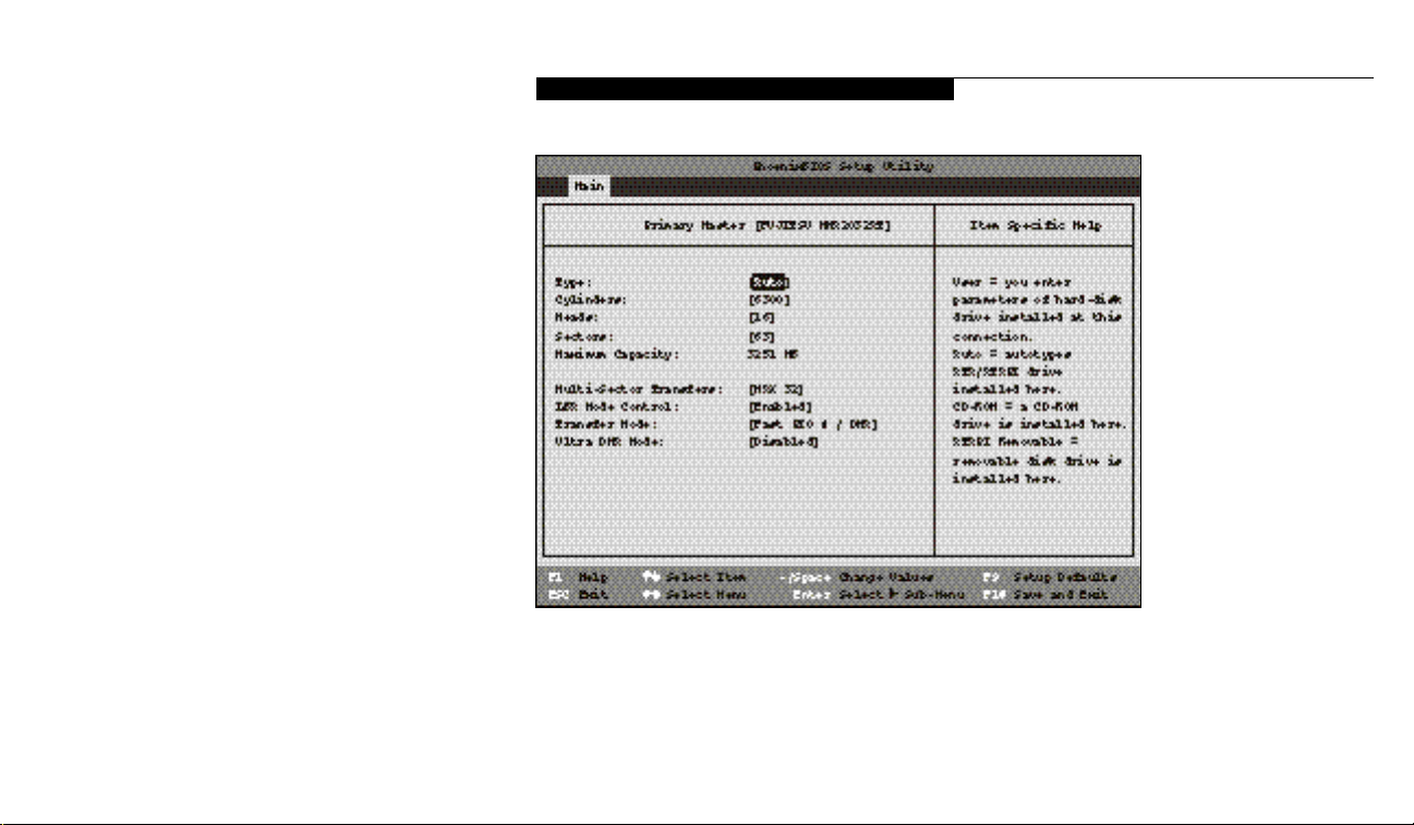
59
Primary Master – Submenu
The Primary Master/Slave, Secondary Master
submenus are identical for hard drives. They
have the capacity displayed at the top of the
screen as well as on Main menu.Follow the
instructions for Navigating Through the Setup
Utility to make any changes. (See page 55.)
Table 3-2 shows the names of the menu fields
for the Primary Master submenu,all of the
options for each field, the default settings and
a description of the field’s function and any
special information needed to help understand
the field’s use.
L i f eB o ok 2 00 Se r ie s f rom F u j it s u
C o n f i g u r i n g Y o u r L i f e B o o k 2 0 0 S e r i e s
Figure 3-2 Primary Master/Slave, Secondary Master Submenus
Page 70

S e c t i o n T h r e e
60
Menu Field Options Default Description
Type: Auto;None;CD-ROM; [Auto] Selects the ATA/ATAPI device type.Select Auto to have the type
User;ATAPIRemovable. automatically identified by the BIOSat POST.If None is selected,
all of the following Set-up items do not appear. Select CD-ROM
if a CD-ROM drive is installed at this connection.If User is
selected, you must specify the number of Cylinders, Heads,
and Sectors for the drive.SelectATAPI Removable if a removable
disk drive is installed at this connection.
Cylinders: A number between 0 This item appears only when Auto is selected and the type is
and 65,535. identified as hard disk, or User is selected.When User is selected,
you can change the value. This field is changed by incrementing
(pressing the Spacebar) or by typing in the number.
Heads: A number between 1 and 16. This item appears only when Auto is selected and the type is
identified as hard disk, or User is selected.When User is selected,
you can change the value. This field is changed by incrementing
(pressing the Spacebar) or by typing in the number.
Sectors: A number between 0 and 63. This item appears only when Auto is selected and the type is
identified as hard disk, or User is selected.When User is selected,
you can change the value. This field is changed by incrementing
(pressing the Spacebar) or by typing in the number.
Table 3-2 Fields, Options and Defaults for the Primary Master/Slave, Secondary Master Submenus
Page 71

L i f eB o ok 2 00 Se r ie s f rom F u j it s u
61
Menu Field Options Default Description
Maximum Capacity: Display only. — Displays the maximum capacity of the drive calculated from the
parameters of the hard disk when Auto is selected and the type
is identified as hard disk, or User is selected.
Multi-Sector Transfers: Disabled; 2; 4; 8;16. — This option cannot be changed when Auto is selected.Specify the
MAX 32;MAX 64;MAX 128. number of sectors per block for multiple sector transfer.MAX
refers to the size the disk returns when required.
LBA Mode Control: Enabled; Disabled. — Enables or disables logical Block Addressing in place of Cylinder,
Head, Sector addressing. This option cannot be changed when
Auto is selected.
Transfer Mode:
S t a n d a rd ,Fast PIO 1; Fast PIO 2;
— Selects the method for moving data to/from the drive.Autotype
Fast PIO 3; Fast PIO 4; the drive to select the optimum transfer mode. This option
Fast PIO 3 / DMA; cannot be changed when Auto is selected. Multi-word DMA
Fast PIO 4 / DMA. is automatically set to mode 1 for Fast PIO 1, Fast PIO 2,
Fast PIO 3, and set to mode 2 for Fast PIO 4 / DMA.
Ultra DMA Mode: Disabled; Mode 0; — Selects the method for moving data to/from the drive.Autotype
Mode 1; Mode 2. the drive to select the optimum transfer mode. This option
cannot be changed when Auto is selected.
Table 3-2 Fields, Options and Defaults for the Primary Master/Slave, Secondary Master Submenus
C o n f i g u r i n g Y o u r L i f e B o o k 2 0 0 S e r i e s
Page 72

S e c t i o n T h r e e
62
C A U T I O N
A bootable CD-ROM may have either
a floppy disk format or a hard drive
format. When the bootable CD-ROM
is used the drive allocations change
automatically without changing the
BIOS setup. If a floppy disk format
CD-ROM is used the CD-ROM becomes
Drive A. If a hard disk format CD-ROM
is used the internal hard drive becomes
Drive D and the CD-ROM becomes
Drive C and all other drive designations
shift as necessary. The boot sequence
ignores the new drive designations,
however, your application software will
use the new designations.
C A U T I O N
Be careful of the operating environment
when booting from a CD-ROM or you
may overwrite files by mistake.
Page 73
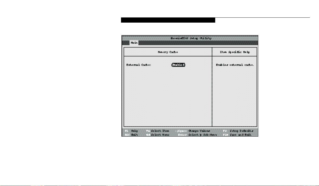
63
Memory Cache – Submenu
The Memory Cache submenu provides the ability to enable or disable external cache memory
for your processor.Follow the instructions for
Navigating Through the Setup Utility to make
any changes. (See page 55.)
Table 3-3 shows the names of the menu fields for
the Memory Cache submenu, all the options for
each field,the default settings and a description
of the field’s function and any special information needed to help understand the field’s use.
L i f eB o ok 2 00 Se r ie s f rom F u j it s u
C o n f i g u r i n g Y o u r L i f e B o o k 2 0 0 S e r i e s
Figure 3-3 Memory Cache Submenu of the Main Menu
Page 74

S e c t i o n T h r e e
64
Menu Field Options Default Description
External Cache: Enabled; Disabled. [Enabled] Turns external memory cache on and off.
Table 3-3 Fields,Options and Defaults for the Memory Cache Submenu
Exiting from the Main Menu
When you have finished setting the parameters
on this menu, you can either exit from the
setup utility,or move to another menu. If you
wish to exit from the setup utility,press the
Esc key or use the cursor keys to go to the
Exit menu.If you wish to move to another
menu,use the cursor keys. (See Navigating
Through the Setup Utility on page 55 for
more information.)
Page 75

65
Table 3-4 shows the names of the menu fields
for the Advanced Menu,all of the options for
each field, the default settings and a description
of the field’s function and any special information needed to help understand the field’s use.
ADVANCED MENU – SETTING
DEVICE FEATURE CONTROLS
The Advanced Menu allows you to:
■
Enable or disable support for Plug & Play
operating systems.
■
Enable or disable BIOS support for ACPI.
■
Set the I/O addresses for the serial and
parallel ports.
■
Set the communication mode for the
parallel port.
■
Set an audio function I/O address,interrupt
level and DMA channel.
■
Select between the display panel and an
external CRT display.
■
Enable or disable compensation for
your display.
■
Configure PCI devices in your system.
Follow the instructions for Navigating
Through the Setup Utility to make any changes.
(See page 55.)
C o n f i g u r i n g Y o u r L i f e B o o k 2 0 0 S e r i e s
L i f eB o ok 2 00 Se r ie s f rom F u j it s u
Figure 3-4 Advanced Menu
Page 76

S e c t i o n T h r e e
66
Menu Field Options Default Description
Plug & Play O/S: Yes;No. [Yes] Select Yes if you are using a Plug & Play capable operating system.
Select No if you need the BIOS to configure non-boot devices.
Secured Setup Yes; No. [No] Yes prevents a Plug & Play operating system from changing
Configuration: system settings.
I/O Device When selected, opens the I/O Device Configuration submenu
Configuration: which allows the user to modify settings for parallel and serial
ports, the floppy disk controller, and the local bus IDE adapter.
Keyboard/Mouse Features: When selected, opens the Keyboard/Mouse Features submenu,
which allows setting external and internal keyboard and
mouse parameters.
Multimedia Device When selected, opens the Multimedia Device Configuration
Configuration: submenu, which allows setting the hardware address and
interrupt levels of audio functions and enabling or disabling
the MIDI/joystick port.
Video Features: When selected, opens the Video Features submenu, which allow
setting of the display parameters,including routing of video
signals to different displays.
Table 3-4 Field Names,Options and Defaults for the Advanced Menu
Page 77

L i f eB o ok 2 00 Se r ie s f rom F u j it s u
67
Table 3-4 Field Names, Options and Defaults for the Advanced Menu
Menu Field Options Default Description
PCI Configuration: When selected,opens additional menus to configure PCI devices.
DMI Event Logging: When selected, opens the DMI event logging configuration menu.
ACPI Features: When selected, opens the ACPI features menu, which allows
enabling and disabling ACPI BIOS.
C o n f i g u r i n g Y o u r L i f e B o o k 2 0 0 S e r i e s
Page 78

S e c t i o n T h r e e
68
C A U T I O N
I/O addresses, DMA channels and
I n t e rrupt levels can be entered in various
ways, including via the BIOS setup utility,
the control software for the I/O device, or
the hard w a re. If any two ports or devices,
serial or parallel, have the same I/O
a d d ress assigned your notebook will not
function norm a l l y. Please keep a re c o rd
of original settings before making any
changes in the event that a restoration is
re q u i red. See your hard w a re and software
documentation as well as the setup utility
to determine settings, limitations, etc.
I/O Device Configuration
Submenu of the Advanced Menu
The I/O Device Configuration submenu
provides the ability to set the I/O addresses and
interrupt levels for the parallel and serial ports,
and disk drive controllers of your notebook.
Figure 3-5 I/O Device Configuration Submenu
Follow the instructions for Navigating
Through the Setup Utility to make any changes.
(See page 55.)
Page 79

C o n f i g u r i n g Y o u r L i f e B o o k 2 0 0 S e r i e s
69
Table 3-5 shows the names of the menu fields
for the I/O Device Configuration submenu,all
of the options for each field,the default settings
and a description of the field’s function and any
special information needed to help understand
the field’s use.
P O I N T
All I/O addresses in Table 3-5 are in
hexadecimal.
L i f eB o ok 2 00 Se r ie s f rom F u j it s u
C A U T I O N
The BIOS will warn you if there is a
re s o u rce conflict by placing a yellow
asterisk next to the device(s) re p o rting
(a) confli c t .
P O I N T
To prevent IRQ and address conflicts,
avoid changing the default settings.
If you must change the settings, you
can call 1-800-8FUJITSU for
technical assistance.
Page 80

S e c t i o n T h r e e
70
Menu Field Options Default Description
Serial Port A: Disabled;Enabled; Auto. [Enabled] Configures the serial port A using either no configuration
(Disabled),a user defined configuration (Enabled), or by
allowing the BIOS or OS to choose the configuration (Auto).
Base I/O address: 3F8; 2F8; 3E8;2E8. [3F8] Allows user to set the serial port base I/O address when port A
is Enabled.
Interrupt: IRQ 3;IRQ 4; [IRQ 4] Allows user to set the serial port interrupt when port A
IRQ 10; IRQ 11. is Enabled.
Serial Port B: Disabled;Enabled; Auto. [Enabled] Configures the serial port A using either no configuration
(Disabled),a user defined configuration (Enabled), or by
allowing the BIOS or OS to choose the configuration (Auto).
Mode: IrDA;FIR. [FIR] Allows user to set the serial port mode when port B is Enabled.
Base I/O address: 3F8;2F8; 3E8;2E8. [2E8] Allows user to set the serial port base I/O address when port B
is Enabled.
Table 3-5 Fields,Options and Defaults for the I/O Device Configuration Submenu of the Advanced Menu
Page 81

L i f eB o ok 2 00 Se r ie s f rom F u j it s u
71
Menu Field Options Default Description
Interrupt: IRQ 3;IRQ 4; [IRQ 3] Allows user to set the serial port interrupt when port B
IRQ 10; IRQ 11. is Enabled.
Base I/O address: 100; 108;110; 118. [118] When the mode for serial port B is set to FIR,this option is
available allowing the user to set the base I/O address for the
FIR of serial port B.
DMA channel: DMA 1;DMA 3. [DMA 3] When the mode for serial port B is set to FIR,this option is
available allowing the user to set the DMA channel for the
FIR of serial port B.
Parallel port: Disabled;Enabled; Auto. [Enabled] Configures the parallel port using either no configuration
(Disabled),a user defined configuration (Enabled), or by
allowing the BIOS or OS to choose the configuration (Auto).
Mode: Output Only; [Bi-directiona1] When the parallel port is enabled this option is available allowing
Bi-directional; ECP. the user to set the mode for the parallel port. Bi-directional allows
two-way transfer of information between your notebook and a
connected parallel device.Output Only (Half Duplex) allows
information to be transferred in only one direction, from your
notebook to the printer or similar device.ECP Mode allows
communication with the ECP class of parallel I/O devices.
C o n f i g u r i n g Y o u r L i f e B o o k 2 0 0 S e r i e s
Table 3-5 Fields,Options and Defaults for the I/O Device Configuration Submenu of the Advanced Menu
Page 82

S e c t i o n T h r e e
72
Menu Field Options Default Description
Base I/O address: 378; 278;3BC. [378] Allows user to set the parallel port base I/O address when the
parallel port is Enabled.
Interrupt: IRQ 5;IRQ 7. [IRQ 7] Allows user to set the parallel port interrupt when the parallel
port is Enabled.
Floppy disk controller: Disabled;Enabled; Auto. [Enabled] Enables and disables the floppy disk drive controller for both
multi-function bays and the external floppy disk drive port.
WhenAuto is selected,allows the BIOS to choose the configura
tion for the controller.
Local Bus IDE Both; Disabled; [Both] E n a bles and disables the integra ted local bus IDE ad a pter.
ad a pter: Pri m a ry;Secon d a ry.
Table 3-5 Fields,Options and Defaults for the I/O Device Configuration Submenu of the Advanced Menu
Page 83
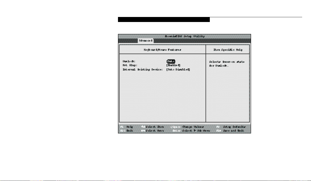
73
Keyboard/Mouse Features Submenu
The Keyboard/Mouse Features submenu is for
setting the parameters of the integrated and
external mouse and keyboard. Follow the
instructions for Navigating Through the Setup
Utility to make any changes. (See page 55.)
Table 3-6 shows the names of the menu fields
for the Keyboard/Mouse submenu,all of the
options for each field,the default settings and
a description of the field’s function and any
special information needed to help understand
the field’s use.
L i f eB o ok 2 00 Se r ie s f rom F u j it s u
C o n f i g u r i n g Y o u r L i f e B o o k 2 0 0 S e r i e s
Figure 3-6 Keyboard/Mouse Features Submenu
Page 84

S e c t i o n T h r e e
74
Menu Field Options Default Description
Numlock: Off; On;Auto. [Auto] Sets the NumLock function state when the computer
completes booting.
Hot Plug: Enabled; Disabled. [Enabled] Enables and disables the ability to plug a mouse or keyboard into
the PS/2 port and have it immediately recognized and active.
Internal Pointing Device: Auto Disabled; [Auto Disabled] Sets the device controlling the mouse cursor on the screen.Always
Always Enabled. Enabled makes the ErgoTrac pointing device always enabled
whether there is an external mouse or not. Auto Disabled makes
the ErgoTrac pointing device turn off when an external pointing
device is connected to the PS/2 port.
Table 3-6 Fields, Options and Defaults of the Keyboard/Mouse Submenu of the Advanced Menu
Page 85
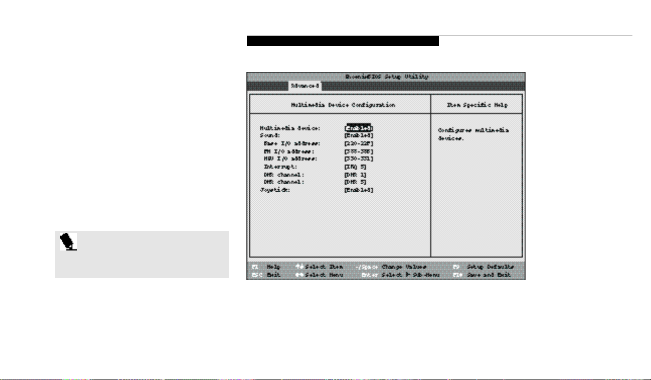
75
Multimedia Device Configuration Submenu
The Multimedia Device Configuration submenu is for setting the features of the built-in
audio functions, and enabling joystick function.
Follow the instructions for Navigating Through
the Setup Utility to make any changes.
(See page 55.)
Table 3-7 shows the names of the menu fields
for the Multimedia Device Configuration submenu,all of the options for each field,the
default settings and a description of the field’s
function and any special information needed
to help understand the field’s use.
P O I N T
All I/O addresses in Table 3-7 are in
hexadecimal.
L i f eB o ok 2 00 Se r ie s f rom F u j it s u
C o n f i g u r i n g Y o u r L i f e B o o k 2 0 0 S e r i e s
Figure 3-7 Multimedia Device Configuration Submenu
Page 86

S e c t i o n T h r e e
76
Menu Field Options Default Description
Multimedia device: Disabled; Enabled. [Enabled] Enables or disables BIOS support for sound and joystick
operation. If Disabled, none of the following items will appear.
Sound: Disabled;Enabled;Auto. [Enabled] Allows BIOS support for sound to be enabled or disabled. When
set to Auto,the BIOS or OS will choose the proper sound configuration settings and some of the following items will not appear.
Base I/O address: 220-22F; 240-24F; [220-22F] When Sound is Enabled,this option is available allowing the user
260-26F; 280-28F. to set the base I/O address for the sound device.
FM I/O address: 388-38B;38C-38F; [388-38B] When Sound is Enabled,this option is available allowing the user
390-393;394-397. to set the base I/O address for the FM device.
MPU-I/O address: 300-301; 310-311; [330-331] When Sound is Enabled,this option is available allowing the user
320-321;330-331. to set the I/O address for the MPU.
Interrupt: IRQ 5;IRQ 7;IRQ 9; [IRQ 5] When Sound is Enabled,this option is available allowing the user
IRQ 10; IRQ 11. to set the interrupt for the sound device.
DMA channel: DMA 0; DMA 1; [DMA 1] When Sound is Enabled,this option is available allowing the user
DMA 3; DMA 5. to set the DMA channel for the sound device.
DMA channel: DMA 0; DMA 1; [DMA 5] When Sound is Enabled,this option is available allowing the user
DMA 3; DMA 5. to set the DMA channel for the sound device.
Joystick: Disabled; Enabled. [Enabled] Enables or disables BIOS support for the joystick.
Table 3-7 Fields, Options and Defaults of the Multimedia Device Configuration Submenu of the Advanced Menu
Page 87
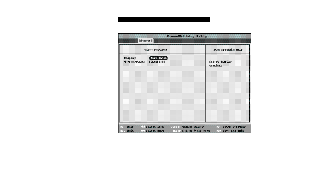
77
Video Features Submenu
The Video Features Submenu is for setting the
display parameters. Follow the instructions for
Navigating Through the Setup Utility to make
any changes. (See page 55.)
Table 3-8 shows the names of the menu fields
for the Video Features submenu,all of the
options for each field, the default settings and
a description of the field’s function and any
special information needed to help understand
the field’s use.
L i f eB o ok 2 00 Se r ie s f rom F u j it s u
C o n f i g u r i n g Y o u r L i f e B o o k 2 0 0 S e r i e s
Figure 3-8 Video Features Submenu
Page 88

S e c t i o n T h r e e
78
Menu Field Options Default Description
Display: Flat-Panel;CRT; [Flat-Panel] Selects where the video signal will be routed.
Simultaneous.
Compensation: Enabled; Disabled. [Disabled] Enables or disables compensation which controls spacing on the
display. When Enabled displays with less than 800 x 600 pixel
resolution will still cover the entire screen.
Table 3-8 Fields, Options and Defaults for the Video Features Submenu of the Advanced Menu
Page 89
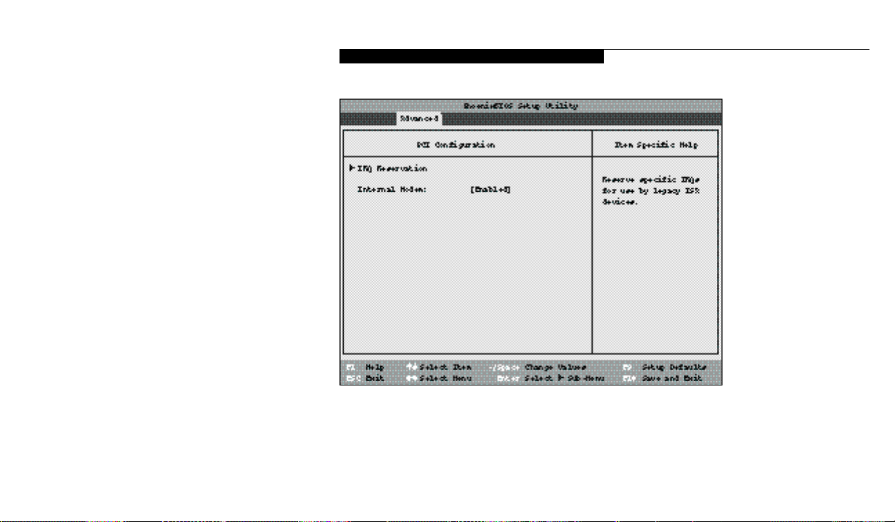
79
PCI Configuration Submenu
The PCI Configuration submenu allows the
user to reserve specific interrupts (IRQs) for
legacy ISA devices,and to enable or disable
built in PCI device modules.Follow the
instructions for Navigating Through the Setup
Utility to make any changes. (See page 55.)
Table 3-9 shows the names of the menu fields
for the PCI Configuration submenu,all of the
options for each field,the default settings and a
description of the field’s function and any special information needed to help understand the
field’s use.
Figure 3-9 PCIConfiguration Submenu
L i f eB o ok 2 00 Se r ie s f rom F u j it s u
C o n f i g u r i n g Y o u r L i f e B o o k 2 0 0 S e r i e s
Page 90

S e c t i o n T h r e e
80
IRQ Reservation: — — Accesses a submenu allowing the user to reserve specific IRQs for
use by legacy ISA devices.
Internal Modem: Disabled; Enabled. [Enabled] Allows the internal modem module to be enabled or disabled.
Table 3-9 Fields,Options and Defaults for the PCI Configuration Submenu of the Advanced Menu
Menu Field Options Default Description
Page 91
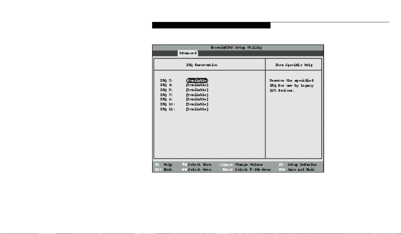
81
IRQ Reservation Submenu of the
PCI Configuration Submenu
The IRQ Reservation submenu of the PCI
Configuration submenu allows the user to mark
various IRQs as reserved for use by legacy ISA
devices.When an IRQ is reserved,the BIOS
does not use it for embedded PCI or ISA
devices. Follow the instructions for Navigating
Through the Setup Utility to make any changes.
(See page 55.)
Table 3-10 shows the names of the menu fields
for the IRQ Reservation submenu of the PCI
Configuration submenu,all of the options for
each field,the default settings and a description
of the field’s function and any special information needed to help understand the field’s use.
Figure 3-10 IRQ Reservation Submenu
L i f eB o ok 2 00 Se r ie s f rom F u j it s u
C o n f i g u r i n g Y o u r L i f e B o o k 2 0 0 S e r i e s
Page 92

S e c t i o n T h r e e
82
Table 3-10 Fields, Options and Defaults for the IRQ Reservation Submenu of the of the PCI Configuration Submenu ofthe Advanced Menu
Menu Field Options Default Description
IRQ 3: Available; Reserved. [Available] Reserves IRQ 3. If Reserved is selected,the BIOS reserves IRQ 3
for use by legacy ISA devices and does not use it for embedded
PCI or ISA devices.IRQ 3 is removed from the IRQ bitmap in
the PCI IRQ routing table.
IRQ 4: Available; Reserved. [Available] Reserves IRQ 4.
IRQ 5: Available; Reserved. [Available] Reserves IRQ 5.
IRQ 7: Available; Reserved. [Available] Reserves IRQ 7.
IRQ 9: Available; Reserved. [Available] Reserves IRQ 9.
IRQ 10: Available; Reserved. [Available] Reserves IRQ 10.
IRQ 11: Available; Reserved. [Available] Reserves IRQ 11.
C A U T I O N
Only IRQ's 9,10, & 11 can be reserved
without resource conflict.
Page 93

83
DMI Event Logging Submenu
of the Advanced Menu
The DMI Event Logging Submenu is for setting
up the logs DMI event logging. Follow the
instructions for Navigating Through the Setup
Utility to make any changes. (See page 55.)
Table 3-11 shows the names of the menu fields
for the DMI Event Logging submenu,all the
options for each field,the default settings and
a description of the field’s function and any
special information needed to help understand
the field’s use.
L i f eB o ok 2 00 Se r ie s f rom F u j it s u
C o n f i g u r i n g Y o u r L i f e B o o k 2 0 0 S e r i e s
Figure 3-11 DMI Event Logging Submenu
Page 94

S e c t i o n T h r e e
84
Menu Field Options Default Description
Event log capacity: Display only. [SpaceAvailable]
Event log validity: Display only. [Valid]
Clear all DMI event logs: Yes; No. [No] AYes selection causes the event logs to clear at the next boot.
Once the logs are cleared this automatically sets to No until reset
to yes by selecting yes here.
Event Logging: Enabled; Disabled. [Enabled] Turns event logging on and off for all DMI events.
System Boot Event: Enabled; Disabled. [Disabled] Turns event logging on and off for DMI system boot events.
Table 3-11 Fields,options and Defaults for the DMI Event Logging Submenu
Page 95

85
ACPI Features Submenu
of the Advanced Menu
The ACPI Features Submenu is for setting up
the Windows 98 Advanced Configuration and
Power Interface parameters. Follow the instructions for Navigating Through the Setup Utility
to make any changes. (See page 55.)
Table 3-12 shows the names of the menu fields
for the ACPI Features submenu,all the options
for each field, the default settings and a descrip tion of the field’s function and any special
information needed to help understand the
field’s use.
L i f eB o ok 2 00 Se r ie s f rom F u j it s u
C o n f i g u r i n g Y o u r L i f e B o o k 2 0 0 S e r i e s
Figure 3-12 ACPI Features Submenu
Page 96

S e c t i o n T h r e e
86
Menu Field Options Default Description
Enable ACPI: Yes; No. [Yes] Turns on and off the Advanced Configuration and
Power Interface.
Table 3-12 Fields, options and Defaults for the ACPI Features Submenu
Exiting from the Advanced Menu
When you have finished setting the parameters
on the Advanced Menu,you can either exit
from setup utility or move to another menu. If
you wish to exit from setup utility,press the Esc
key to go to the Exit menu. If you wish to move
to another menu,use the cursor keys.
P O I N T
ACPI features in your notebook will not
be available until Windows 98.
Page 97
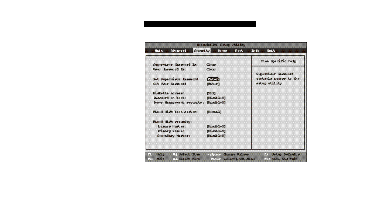
87
SECURITY MENU – SETTING THE
SECURITY FEATURES
The Security menu allows you to set up the data
security features of your notebook to fit your
operating needs and to view the current data
security configuration. Follow the instructions
for Navigating Through the Setup Utility to
make any changes. (See page 55.)
Table 3-13 shows the names of the menu fields
for the Security menu,all of the options for
each field,the default settings and a description
of the field's function and any special information needed to help understand the field's use.
The default condition is no passwords required
and no write protection.
L i f eB o ok 2 00 Se r ie s f rom F u j it s u
C o n f i g u r i n g Y o u r L i f e B o o k 2 0 0 S e r i e s
Figure 3-13 Security Menu
Page 98

S e c t i o n T h r e e
88
P O I N T
If you set a password, write it down and
keep it in a safe place. If you forget the
password you will have to contact your
support representative to regain access to
your secured functions and data.
C A U T I O N
Entering a password incorrectly 3 times
in a row will cause the keyboard and
mouse to be locked out and the warning
[System Disabled] to be displayed. If
this happens restart the computer by
turning off and on the power with the
power switch and use the correct
password on reboot.
P O I N T
If you make an error when re-entering
the password a [ W a r n i n g ] will be
displayed on the screen. To try again
press the Enter key and then retype the
password. Press the Esc key to abort
the password setting process.
C A U T I O N
If the Power Management Security is
Enabled and the Password on Boot is
Disabled you will not be able to resume
operation from the Suspend or Save-toDisk modes.
Page 99

L i f eB o ok 2 00 Se r ie s f rom F u j it s u
89
Menu Field Options Default Description
Supervisor Password is: — Clear. A display-only field.Set is displayed when the system
supervisor password is set and Clear when it is not.
User Password is: — Clear. A display-only field.Set is displayed when the general user
password is set,and Clear when it is not.
Set Supervisor Password: [Enter] — Sets,changes or cancels the Supervisor Password. The Supervisor
Password may be up to seven characters long and must include
only lower-case letters or numbers. To cancel a password press the
Enter key instead of entering characters in the Enter New
Password field and in the Re-enter New Password field.When a
Supervisor Password is set it must be used to access the BIOS
setup utility.
Set User Password: [Enter] — (This field can only be accessed if the Supervisor Password is set.)
Sets, changes or cancels the User Password. The User Password
may be up to seven characters long and must include only lower
case letters or numbers. To cancel a password press the Enter key
instead of entering characters in the Enter New Password field and
in the Re-enter New Password field.When a User Password is set
it must be used to access the BIOS setup utility.
Table 3-13 Fields, Options and Defaults for the Security Menu
C o n f i g u r i n g Y o u r L i f e B o o k 2 0 0 S e r i e s
Page 100

S e c t i o n T h r e e
90
Menu Field Options Default Description
Diskette access: All; Supervisor Only. All Sets the floppy disk access to be secured for access only with
Supervisor's password or by all users with a password. The default
is all users with a password.
Password on boot: Enabled; Disabled. Disabled When set to Enabled,a password (User or Supervisor) is required
after the Power On Self Test (POST) before the operating system
will be read from a disk. When set to Disabled no password is
required.If no Supervisor Password is set this feature is not
available and no password is required.
Power Management Enabled;Disabled. Disabled
Wh en set to Enabl ed ,a password (Us er or Su pervi s or) is requ i red
Sec u ri ty: to re sume from Su s pend or Save - to - Disk mode .The password
requ i red is the same one requ i red by the Pa s s word on Boot functi on .
Fixed disk boot sector: Normal;Write Protect. [Normal]
Sets write protection for the sector of the boot disk which contains
the operating system. When set to Write Protect,the BIOS will
prevent any application from writing into the sector of the internal
hard drive containing the operating system. When set to Normal
there is no BIOS protection of the operating system.
Table 3-13 Fields, Options and Defaults for the Security Menu
 Loading...