

Page 1
P3PC-E842-01EN
fi-4340C Image Scanner
Cleaning and Maintenance
Page 2

Page 3

Revisions, Disclaimers
Edition
01 October, 2001 First edition
Specification No. P3PC-E842-01EN
Changes
The contents of this manual may be revised without prior notice.
PFU reserves the right to make changes to any products herein, to improve
reliability, function, or design, without further notice and without obligation.
Copyrights
All Rights Reserved, Copyright © 2001, PFU LIMITED.
Printed in Japan.
No part of this manual may be reproduced in any form without permission.
Date published Revised contents
i
Page 4

Fujitsu Group Offices
Please send your comments on this manual or on Fujitsu products to the following
addresses:
FUJITSU COMPUTER PRODUCTS OF
AMERICA, INC.
2904 Orchard Parkway, San Jose,
California CA95134-2009, U.S.A.
Phone: (1-800)591-5924;
(1-408)432-6333
Technical Assistance Center:
(1-800)626-4686
Fax: (1-408)894-1709
Website: http://www.fcpa.com/
E-mail: info@fcpa.fujitsu.com
FUJITSU EUROPE LTD.
Hayes Park Central, Hayes End Road,
Hayes Middlesex UB4 8FE, England
Phone: (44-208)573-4444
Fax: (44-208)573-2643
Website:
http://www.fujitsueurope.com/home/
E-mail: iwebmaster@fujitsu-europe.com
FUJITSU NORDIC AB
Kung Hans Vag 12, S-192 68
Sollentuna, Sweden
Phone: (46-8)626-45-00
Fax: (46-8)626-45-88
Website:
http://www.fujitsu-europe.com/
home/
FUJITSU CANADA, INC.
2800 Matheson Boulevard East,
Mississauga, Ontario L4W 4X5, Canada
Phone: (1-905)602-5454
Fax: (1-905)602-5457
Website: http://www.fujitsu.ca/
E-mail: imaging@fujitsu.ca
(For Sales Questions)
scantech@fujitsu.ca
(For technical questions)
FUJITSU DEUTSCHLAND GMBH.
Frankfurter Ring 211, 80807 Munchen
40, Germany
Phone: (49-89)323-78-0
Fax: (49-89)323-78-100
Website: http://www.fujitsu.de/"
E-mail: webmaster@fujitsu.de
FUJITSU ITALIA S.p.A.
Via Nazario Sauro, 38
20099 Sesto San Giovanni (Milan), Italy
Phone: (39-02)26294-1
Fax: (39-02)26294-201
Website:
http://www.fujitsu-europe.com/
home/
FUJITSU FRANCE S.A.
1, Place des Etats-Unis, Silic 310,
94588 Rungis Cedex, France
Phone: (33-1)41-80-38-88
Fax: (33-1)41-80-3850
Website:
http://www.fujitsu-europe.com/home/
ii
FUJITSU ICL ESPAÑA, S.A.
Camino Cerro de los Gamos, 1 28224,
Pozuelo de Alarcon, Madrid, Spain
Phone: (34-91)784-9000
Fax: (34-91)784-9317
Website:
http://www.fujitsu-europe.com/home/
E-mail: imagemaster@mail.fujitsu.es
Page 5

FUJITSU AUSTRALIA LTD
2 Julius Avenue
North Ryde, N.S.W 2113 Australia
Phone: (61-2)9776-4555
Fax: (61-2)9776-4556
CompuServe: GO FUJITSU
Website: http://www.fujitsu.com.au/
FUJITSU COMPUTER (SINGAPORE)
PTE.LTD.
20 Science Park Road, #03-01, Tele
Teck Park Singapore Science Park II,
Singapore 117674
Phone: (65)777-6577
Fax: (65)771-5499
Website:
http://www.fujitsu-computers.com.sg
E-mail: inquiry@fcsl.fujitsu.com.sg
FUJITSU TAIWAN LTD.
19th Fl., No39, 1 Sec. chung-Hwa Rd.,
Taipei, Taiwan R.O.C.
Phone: (886-2)2311-2255
Fax: (886-2)2311-2277
FUJITSU SYSTEMS BUSINESS
(THAILAND) LTD.
12th Fl., Olympia Thai Tower, 444
Rachadapisek Road, Samsennok,
Huay kwang, Bangkok 10320, Thailand
Phone: (662)512-6066
Fax: (662)512-6068
FUJITSU SYSTEMS BUSINESS
(MALAYSIA) SDN, BHD.
Fujitsu Plaza 1A, Japan Tandang 204,
P.O.Box 636, Jalan Sultan, 46770,
Petaling Jaya Selangor Darul
Ehsan, Malaysia
Phone: (60-3)793-3888
Fax: (60-3)7783-0888
FUJITSU HONG KONG LTD.
10/F., Lincoln House, 979 King's Road,
Taikoo Place, Island East, Hong Kong
Phone: (852)2827-5780
Fax: (852)2827-4724
E-mail: scanner@fujitsu.com.hk
FUJITSU KOREA LTD.
5-11 Fl., Coryo Finance Center Building,
Youido-Dong 23-6, Young DungPo-gu,
Seoul, Korea, 150-010
Phone: (82-2)3787-5970
Fax: (82-2)3787-6070
Website: http://www.fujitsu.co.kr
E-mail: webmaster@fkl.fujitsu.co.kr
FUJITSU PHILIPPINES, INC
2nd Fl., United Life Building, Pasay
Road, Legaspi Village Makati,
Metro Manila, Philippines
Phone: (63-2)812-4002
Fax: (63-2)817-7576
Computer Products Business Group
658-1 Tsuruma Machida-shi, Tokyo
194-8510, Japan
Phone: (81-42)796-5211
Fax: (81-42)788-7651
Website: http://www.pfu.fujitsu.com/
E-mail: scanners@pfu.fujitsu.com
Corporate headquarters
Nu 98-2 Unoke, Unoke-machi,
kahoku-gun, Ishikawa 929-1192, Japan
Phone: (81-76)283-1212
Fax: (81-76)283-4689
iii
Page 6

Note, Liability
READ ALL OF THIS MANUAL CAREFULLY BEFORE USING THIS PROD-UCT. IF
NOT USED CORRECTLY, UNEXPECTED INJURY MAY BE CAUSED TO USERS
OR BYSTANDERS.
While all efforts have been made to ensure the accuracy of all information in this
manual, PFU assumes no liability to any party for any damage caused by errors or
omissions or by statements of any kind in this manual, its updates or supplements,
whether such errors are omissions or statements resulting from negligence,
accidents, or any other cause. PFU further assumes no liability arising from the
application or use of any product or system described herein; nor any liability for
incidental or consequential damages arising from the use of this manual. PFU
disclaims all warranties regarding the information contained herein, whether
expressed, implied, or statutory.
iv
Page 7

Preface
This manual explains how to clean and maintain the fi-4340C image scanner.
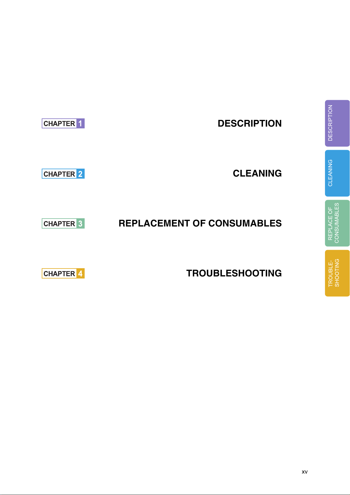
This manual contains chapters on the following topics:
DESCRIPTION
CLEANING
REPLACEMENT OF CONSUMABLES
TROUBLESHOOTING
Refer to "Operator’s Guide" for basic information about the fi-4340C.
For instructions on how to install the device driver, refer to the "Installation Guide" or
the device driver CD.
The fi-4340C is a very fast and highly functional color image scanner developed for
high quality color image processing, using charge-coupled device (CCD) color
image sensors. This scanner features high-speed duplex scanning with an automatic document feeder (ADF).
v
Page 8

Conventions
Important information that requires special attention is indicated as follows:
WARNING
WARNING indicates that serious personal injury may result if you do not follow a
procedure correctly.
CAUTION
CAUTION indicates that minor personal injury, loss of data, or damage to the
scanner may result if you do not follow a procedure correctly.
Official PFU part names are indicated with an initial capital letter, as in the part
name “Pick roller”.
NOTE
A NOTE provides “how-to” tips or suggestions to help you perform a procedure
correctly.
vi
Page 9
Precautions
This section describes precautions to follow when installing the scanner.
To ensure the longevity and proper functioning of your scanner, do not install the
scanner in the places and environments described below.
■
Warning
Important warnings employed in this manual are as follows.
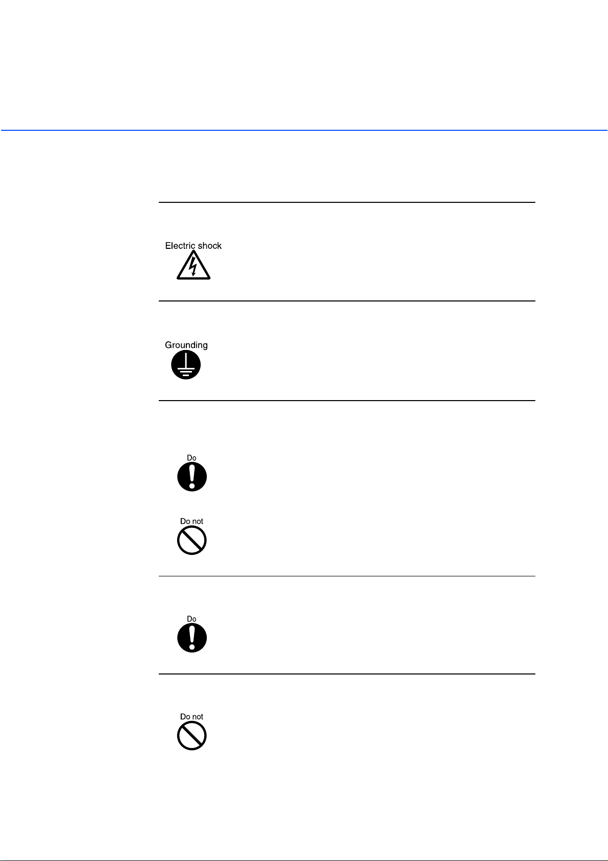
Do not damage the power cable.
Damage to the power cable may result in fire or electric shock.
Do not place heavy objects on, pull, tightly bend, twist, heat, or
modify the power cable.
Do not use the power cable or socket if it is damaged, or if the plug
is loose in the socket.
Use only the specified power cable or extension cable.
Use only the specified power cable or extension cable. Use of other
cables may result in electric shock or malfunction.
Use only at the specified voltage. Ensure that too many cables
are not connected to the same socket.
Use at other than the specified voltage may result in fire or electric
shock.
Ensure that too many cables are not connected to the same socket.
Wipe all dust from plug on the power supply cable.
Using a dry cloth, remove all dust on the metal components of the
plug, and on all surfaces to which the metal components are
attached.
Presence of dust may result in fire or electric shock.
vii
Page 10
Do not use the equipment in areas with high levels of oil smoke,
steam, humidity, or dust.
Installation in areas with high levels of oil smoke, steam, humidity,
or dust may result in fire or electric shock.
Do not use the equipment if an abnormal smell is apparent.
If the equipment overheats, emits smoke or abnormal smells, or
makes abnormal noises, switch power OFF immediately and
remove the power plug from the socket.
Check that smoke is no longer emitted, and call your dealer or
maintenance service center. Do not attempt to repair the equipment
yourself under any circumstances.
Ensure that water or foreign matter does not enter the
equipment.
Do not insert or drop metal objects or combustible objects into
openings (eg. ventilation openings).
Ensure that liquids (eg. coffee) and metal objects (eg. paper clips)
do not enter the equipment.
Do not spill or leak water onto the equipment.
If foreign matter (eg. water, other liquids, metal objects) enters the
equipment, switch power OFF immediately and remove the power
plug from the socket, and call your dealer or maintenance service
center. Particular care is required if children are in the vicinity.
viii
Page 11
Do not open the equipment without good reason.
The equipment contains high-voltage components, and should not
be dismantled or modified.
Always remove the plug from the socket before fitting or
removing optional equipment.
Switch the equipment power supply OFF, and remove the plug from
the socket, before fitting or removing optional equipment in
accordance with the specified procedure.
Grip the plug to remove the power cable from the socket.
Do not move the equipment alone.
Never move the equipment alone.
Switch power OFF if the equipment is damaged.
If the equipment is dropped, or covers etc. have been damaged,
switch power supply OFF, remove the plug from the socket, and call
your dealer or maintenance service center.
Do not place in wet areas.
Do not place the scanner where liquid spills may occur.
ix
Page 12
■
Caution
Important cautions employed in this manual are as follows.
Do not touch the power cable with wet hands.
Do not remove or insert the plug with wet hands. Wet hands may
result in electric shock.
Earth the equipment.
his equipment must be earthed. Always connect the power cable to
a 3-pin socket. If earthing is not possible, call your dealer or
maintenance service center.
Always ensure that the equipment is installed in the stable
location.
Ensure that no part of the scanner is liable to fall from the desk, and
that the base of the equipment is level.
Ensure that the equipment is installed in a stable location. The
equipment should be installed in a location which is level and
subject to minimal vibration.
Insert the power plug fully into the socket.
Ensure that the power plug is inserted as far as possible into the
socket.
Do not block the ventilation openings.
If the ventilation openings are blocked the interior of the equipment
will overheat, and may result in fire or malfunction.
x
Page 13
Do not place heavy objects on, and do not stand on, the
equipment.
Placing heavy objects on the equipment, or standing on the
equipment while working, may result in injury.
Remove the power plug from the socket before moving the
equipment.
Moving the equipment with the cable connected may result in
damage to the cable, fire or electric shock, or injury. Always remove
the power plug from the socket, and disconnect extension cables,
before moving the equipment.
Always clear the floor before beginning work.
Avoid static electricity.
Ensure that the equipment is installed away from strong magnetic
fields, sources of electrical noise and air flow.
If the scanner is used near an air conditioner, copying machine, or
TV set, the scanner may operate incorrectly.
Avoid static electricity. Static electricity may be a cause of misoperation of the equipment. Ensure that the floor and desk on which
the equipment is installed is of a material which does not generate
static electricity.
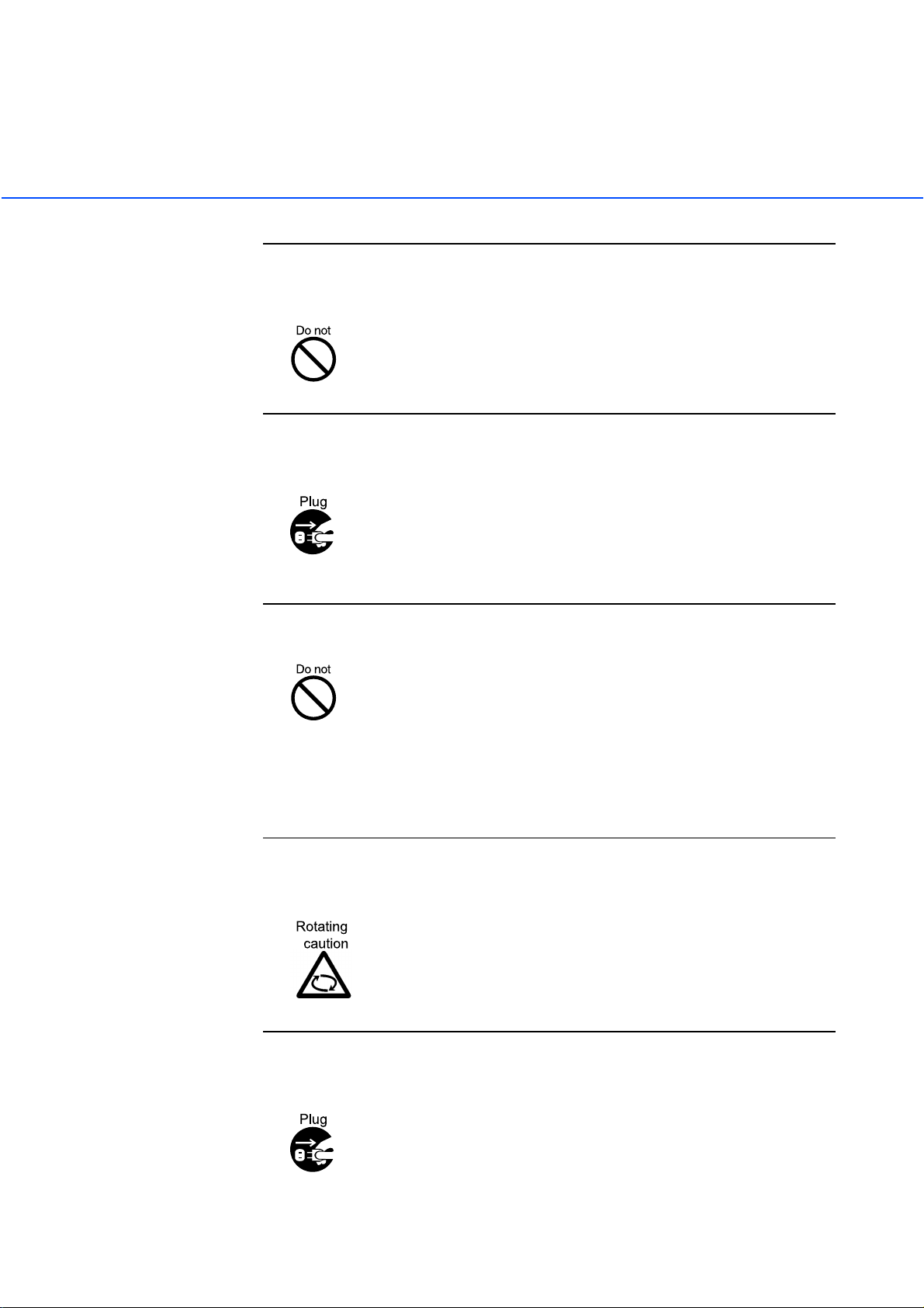
Ensure that clothing, ties, and hair do not become caught in
gears and rollers.
Clothing, ties, and hair becoming caught in moving components
such as gears and rollers may result in injury.
Remove the power plug from the socket if the equipment is to be
out of use for a considerable length of time.
For safety reasons, the power plug should be removed from the
socket if the equipment is to be out of use for a significant time.
xi
Page 14

Remove the power cable from the socket immediately thunder is
heard.
Remove the power cable from the socket if thunder is heard nearby.
The equipment may be damaged if it remains connected during an
electrical storm.
Do not leave the equipment in direct sunlight.
Leaving the equipment in direct sunlight or in the vicinity of airconditioning equipment will result in the internal temperature of the
equipment increasing, and may result in fire or malfunction.
Ensure that the equipment is installed in a well ventilated area.
xii
Page 15

CONTENTS
CHAPTER 1 DESCRIPTION ........................................... 1-1
❏
CHAPTER 2 CLEANING ................................................2-1
❏
CHAPTER 3 REPLACEMENT OF CONSUMABLES ..... 3-1
❏
Units ........................................................... 1-2
Assemblies ................................................. 1-4
Operator panel ........................................... 1-5
Panel Display ............................................. 1-7
Cleaning Supplies and
Areas Requiring Cleaning ....................... 2-2
Supplies ........................................... 2-2
Areas Requiring Cleaning ................ 2-3
Cleaning the ADF ....................................... 2-4
Cleaning the Document bed ....................... 2-9
Consumable Lists ....................................... 3-2
Pad ASSY .................................................. 3-3
Pick Roller .................................................. 3-5
CHAPTER 4 TROUBLESHOOTING ............................... 4-1
❏
Clearing Paper Jams .................................. 4-2
Initial Checks .............................................. 4-3
NOTES ..................................................... 4-13
Problem Checklist .................................... 4-20
xiii
Page 16

xiv
Page 17
CHAPTER
1
DESCRIPTION
DESCRIPTION
CHAPTER
CHAPTER
CHAPTER
2
3
4
REPLACEMENT OF CONSUMABLES
TROUBLESHOOTING
CLEANING
CLEANING
REPLACE OF
CONSUMABLES
TROUBLE-
SHOOTING
xv
Page 18

xvi
Page 19

CHAPTER
1
DESCRIPTION
This chapter describes units, assemblies, indicators and LED functions.
Units
Assemblies
Operator panel
Panel Display
●
1-1
Page 20
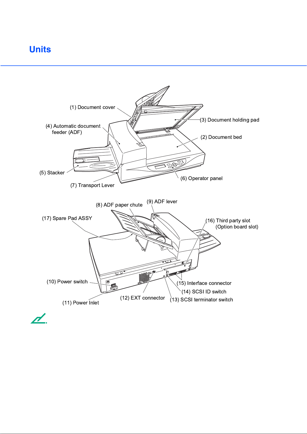
Units
(4) Automatic document
(5) Stacker
(1) Document cover
(3) Document holding pad
feeder (ADF)
(2) Document bed
(6) Operator panel
(7) Transport Lever
(8) ADF paper chute
(17) Spare Pad ASSY
(10) Power switch
(12) EXT connector
(11) Power Inlet
NOTE
The Transport lever should be switched to the operating position when the scanner is to be used. Refer to
"Operator’s Guide" for details of Transport lever.
(9) ADF lever
(16) Third party slot
(Option board slot)
(15) Interface connector
(14) SCSI ID switch
(13) SCSI terminator switch
●
1-2
Page 21

No. Part Function
1 Document cover Closes over and keeps in place the document to be read.
2 Document bed Holds document to be read. Also called Flatbed (FB).
3 Document holding pad Presses document to the Document bed.
4 Automatic document feeder
Automatically feeds documents to the reading position.
(ADF)
5 Stacker Stacks the read documents.
6 Operator panel Contains indicator panel that indicates scanner status.
7 Transport Lever Transport lever Secures the carrier unit. Set to locked position
when moving scanner.
8 ADF paper chute Holds the documents to be fed by the automatic document
feeder (ADF).
9 ADF lever Opens/closes the ADF to enable the removal of documents
jammed in the feeder.
10 Power switch Turns the power On or Off.
11 Power inlet Connects to an AC power outlet with the power cable.
12 EXT connector Connects to an optional imprinter.
DESCRIPTION
13 SCSI terminator switch Set to ON when the image scanner is the final device on the
SCSI daisy chain. Otherwise, set to OFF.
14 SCSI-ID switch Sets the SCSI ID. (Default ID is 5.)
15 Interface connectors Connect to the host system with interface cables.
16 Third party slot A Fujitsu VIDEO INTERFACE OPTION BOARD or
fi-CMP3 (JPEG COMPRESSION BOARD) is installed.
17 Spare Pad ASSY Spare Pad ASSY. (One spare Pad ASSY is provided as the
default setting.)
●
1-3
Page 22

Assemblies
Stacker
Pick rollers
Pad ASSY
Guide A ASSY
●
1-4
Page 23

Operator panel
The Operator panel is located on the upper right hand side of the scanner. The panel consists of a status
display (16 characters x 2 lines), LEDs, and control buttons.
■
Layout
Operator panel
DESCRIPTION
Exit
Enter
Previous
Next
Stop
Send To/
Start
Read
Check
●
1-5
Page 24

■
Button/LED Function
Name of the button and LED
Button
Next
Previous
Exit When you are entering settings on the Operator panel, pressing this
Enter Enters the parameter currently selected by the cursor.
Send To/ Start Operational only when Manual start mode is set or the Read lamp
Stop When the Check LED lights, pressing this button releases the error
Function
Displays the next LCD screen.
Displays the previous LCD screen.
Moves the cursor to the left.
Moves the cursor to the right.
button returns you immediately to the Scanner Ready screen.
lights; Starts the reading when video interface option is used. Some
application software packages make use of this button.
status (turns off Check and returns to the Scanner Ready screen).
Operational only during the reading operation; stops the reading
when the video interface option is used.
Also turns off the Check lamp.
LED Indicates that the scanner is On.
Read Indicates the scanner is reading or ready to read.
• If lit, this indicates that an alarm occurred. Pressing the Stop button turns the Check lamp Off.
• If it blinks at one second intervals, this means that a jam or double feed has been detected. If the problem is jammed paper,
removing the jammed paper turns off the Check lamp. If the
problem is double feed, pressing the Stop button turns off the
Check lamp.
• If it blinks at four seconds intervals, this means that cleaning the
ADF is necessary.
●
Check
1-6
Page 25

Panel Display
■
Counter Display
The displays for the Paper and Abrasion counters are shown below:
Paper counter
XXX
Re ad
y
XXXXX0
Abrasion counter
Simultaneously press the and arrow buttons for at least 1 second, to switch to Life counter panel
display as shown below:The scanner is provided with a counter display.
X
>
DESCRIPTION
Re ad
y
XXXXXX0
*
>
Life counter
Counter Function
Paper counter
When the
button is pressed for
at least 1 second
The paper counter counts the number of scanned sheets from
the start of reading until Paper Empty or an error is detected.
The counter is automatically reset at the start of reading. The
counter is used for checking the number of sheets scanned at
one batch.
When the
button is pressed for
at least 1 second
This counter increments each time a document is scanned. It is
not initialized until the power is turned off. The counter can be
used, for example, for checking the number of sheets that have
been scanned in one day.
Abrasion
counter
The abrasion counter counts the accumulated number of scanned sheets. This counter
increments at every 10 sheets. It is useful to check the cleaning cycle or the parts
replacement cycle. How to reset is described in "Operator’s Guide".
Life Counter Keeps a cumulative count of the number of scans made after shipping.
This counter increments by 1 after every 10 scans and may be used to estimate of the
device's remaining scan life.
NOTE
When the counter value is 0, no number is displayed.
●
1-7
Page 26

■
Operation status
The operation status is indicated by the following messages:
<Power-on>
W
ar mi n
g
up Now!
-
!
<Reading>
No w
R
adi ng!
e
<Low Power Mode> When the Scanner Display turns Off and the power indicator remains
“On”, the scanner is in the Low Power Mode.
NOTE
One of the following will wake up the scanner:
• Pressing any button.
• Setting the paper on the ADF.
• Sending a command from the host computer.
<Waiting for Start> (Only When the Video Interface Option is installed.)
The scanner displays the following screen when waiting for the Start
button to be pressed:
S
tart
S
W
ON!
<Cleaning request> When the Pick roller cleaning is necessary, the scanner displays the
following on the upper line:
ean
l
C
P
c
i
rolle
k
r
When the ADF glass cleaning is necessary, the scanner displays the
following on the LCD:
ean
l
C
A
FGlass
D
Clean the Pick roller or the ADF glass in accordance with the
instructions given in "2 CLEANING" (Page 2-1).
1-8
●
Page 27

■
Temporary error
<Hopper empty>
<Jam>
<ADF cover open>
Pape
r
Empt y
This message is displayed if there is no more document on the ADF
paper chute during a read operation in ADF mode. Fill the ADF paper
chute with document. To enable the read operation, press the stop
button.
Pap
e
r
Jam
This message is displayed if a document is jammed in the ADF. See
"4 TROUBLESHOOTING" (Page 4-1) for removing jammed
documents.
ADF- C
o
er Open
v
This message is displayed if the ADF is not closed completely. Close
the ADF completely, and enable the read operation.
DESCRIPTION
<Double feed error>
Dou
b
eFeed
l
This message is displayed when the ADF detects a Double feed error.
Check the document and re-scan it.
1-9
●
Page 28

■
Alarm
One of the following messages is displayed if an error occurs in the scanner. If one of the following error
messages is displayed, turn the power Off and then On again. If the same message is displayed, contact
your service representative.
<Optical alarm front>
<Optical alarm back>
<FB mechanism alarm>
Fr ont
O
pt i ca
Fr ont
Bac k
O
O
pt i ca
pt i ca
Bac k
latbe
F
O
pt i ca
M
echan
l
S
l
l
S
d
l
i
ide
S
Al ar m
de
ide
i
S
Al ar m( G
Al ar m
de
i
Al ar m( G
al Al ar
c
NOTE
When the total number of sheets scanned by the ADF is less than 100, the message above and the
message below are displayed alternately.
Remove the bracket (Transport lever) that holds the unit. Refer to "Operator’s Guide" for details of
operation.
Chec k
Loc
k
hi ppi ng
S
<Motor fuse alarm>
)
)
m
<Lamp fuse alarm>
<Image transfer alarm>
<Memory alarm>
<EEPROM alarm>
1-10
●
M
ot or f
Lampf
I
mg T r
Me mo
EEPR
u
u
a
r
O
eAlarm
s
eAlarm
s
sAlarm
n
y
M
Al ar m
Al ar m
Page 29

<FAN alarm>
FAN
larm
A
<SCSI fuse alarm>
SCSI f
u
eAlarm
s
<IPC Board alarm>
(IPC-4D (Image Processing Circuit
Board))
I
PC Bo
a
dAlarm
r
NOTE
When this message is displayed, turn Off system power and then turn it On again. Alternatively, replace
the current cable with one recommended by the manufacturer of the SCSI board. When the cause of the
alarm has been corrected, the scanner automatically resumes operation once power is turned On again.
<Self-diagnostics Error>
DESCRIPTION
The Power indicator and Check lamp blink alternately.
●
1-11
Page 30

●
1-12
Page 31

CHAPTER
2
CLEANING
This chapter describes cleaning supplies, areas that require cleaning, and
procedures for cleaning the ADF and the Document bed.
Cleaning Supplies and Areas Requiring Cleaning
Cleaning the ADF
Cleaning the Document bed
●
2-1
Page 32

Cleaning Supplies and Areas Requiring Cleaning
Document cover
Document holding pad
Document bed
Supplies
Supplies Supply No. Frequencies (*1)(*3) Remarks
Cleaning paper Contact your
dealer or
distributor.
Cleaner F2
Cleaner F1 or Isopropyl
alcohol
Cotton swab
• Every 5,000 sheets
• Apply Cleaner F1 to the
cleaning paper before
using.
• Plastic rollers (*2)
• Pad ASSY
Every 5,000 sheets
• Pick roller/Feed rollers/
Glass/Sheet guide
Every 5,000 sheets
10 sheets.
1 bottle
Apply Cleaner F2 to
cotton swab.
1 bottle.
Apply Cleaner F1 to
cloth.
Dry cloth
For more information on cleaning supplies, contact your dealer.
*1: If the display on the operator panel shows "Clean Pickroller", then clean it regardless of the
frequencies recommended here.
CAUTION
*2: Do not clean the rubber rollers with cleaner F2.
*3: Refer to the Abrasion counter on the Operator panel to estimate when the next cleaning is necessary.
NOTE
When the following paper types are used, it may be necessary to clean more frequently:
• Paper with a smooth surface, such as coated paper.
• Paper almost entirely covered with printing.
• Paper with special chemical coatings, such as carbonless paper.
• Paper including a great quantity of calcium.
• When reading a great many documents written with a pencil.
●
2-2
Page 33

Areas Requiring Cleaning
Area Name
Document
bed
ADF
Document holding pad
Document bed
Pad
Glass/Sheet guide
Pick roller
Plastic rollers
Feed rollers
Pick Arm Rollers
Cleaning paper
with Cleaner F1
ADF
Dry cloth
with Cleaner F1
Document holding
pad
Document bed
Cotton swab
with Cleaner F1 or F2
CLEANING
Plastic rollers
Glass
Plastic rollers
Feed rollers
Pad
Pick rollers
Sheet guide (white paper)
Plastic rollers
●
2-3
Page 34

Cleaning the ADF
■
Cleaning the ADF with cleaning paper
Pull the ADF lever to open the ADF.
1
Apply cleaner F1 to a new piece of
2
cleaning paper.
Place the cleaning paper on the ADF
3
so that the edge of the short side
touches the Plastic roller.
Close the ADF and turn the power
4
on to start the cleaning.
Turn the power off.
5
Repeat steps 1 through 5.
6
Cleaning paper
Cleaning
paper
Plastic
rollers
pow-on
●
2-4
Page 35

■
Cleaning the Pad ASSY with a Dry cloth or a Cloth with Cleaner F1
Pull the ADF lever to open the ADF.
1
Use a dry cloth or a cloth moistened
2
with Cleaner F1 to softly remove dirt
and dust as follows.
Pad ASSY:
Wipe the pad in a downward direction (as
indicated by the arrow). Be careful not to
catch the spring for the Pick when wiping.
Glass:
Wipe the glass lightly.
Pad ASSY
Spring for the Pick
CLEANING
NOTE
If the glass is dirty, the image may include black
vertical stripes.
CAUTION
Don’t touch the glass immediately following a scan.
The hot glass can cause burn.
Pick roller:
Wipe the roller.
Be careful not to damage the mylar
strip of the Pick roller.
Glass
Mylar strip
(transparent sheet)
Pick rollers
●
2-5
Page 36

Feed rollers:
and Plastic rollers
Wipe the rollers.
Be careful not to damage the surface of the
rollers.
Feed rollers
Sheet guide (white part):
Wipe the sheet guide.
NOTE
If the Sheet guide is dirty, the front image may show
vertical stripes.
Feed rollers
Plastic rollers
Sheet guide (white part)
Plastic rollers
●
Close the ADF to lock the ADF lever.
3
2-6
Page 37

■
Cleaning the Pick Arm Rollers
Pull the ADF lever to open the ADF.
Plastic rollers Pick Arm
1
Moisten a cotton swab or Dry cloth
2
with F1 or F2 Cleaner.
Wipe the small Plastic rollers at the
3
tip of the Pick Arm.
Wipe the small Plastic rollers and the
4
Pick Arm with a clean, dry cloth to
dry them.
NOTE
When non-carbon paper is used, the Pick Arm rollers may become dirty with a black substance. Use
Cleaner F2 to remove the contamination.
CAUTION
1. Don’t wipe the pad rubbers with the F2 cleaner.
2. Don’t apply the F2 cleaner to the pad rubber.
CLEANING
●
2-7
Page 38

■
Cleaning the Plastic rollers with Cleaner F2
Pull the ADF lever to open the ADF.
1
Moisten a cotton swab with Cleaner
2
F2.
Wipe the Plastic roller surfaces.
3
CAUTION
Don’t wipe the Pick Rollers with a cotton swab using
cleaner F2.
Wipe the Plastic roller surface with a
4
clean, dry cloth. Allow it to dry.
Plastic rollers
Plastic rollers
●
2-8
Page 39

Cleaning the Document bed
■
Cleaning the Document Bed with a Cloth and Cleaner F1
Document cover
Document holding pad
Document bed
NOTE
Window or glass cleaner, excluding those not allowed for plastic, can be used instead of cleaner F1.
However, do not use organic solvents like thinner.
Open the Document cover.
1
Apply Cleaner F1 to a clean cloth.
2
Wipe the Document holding pad and
3
the Document bed.
Allow them to dry.
4
NOTE
Be sure to prevent liquid from seeping through the opening between the Document bed and the plastic
cover.
CLEANING
●
2-9
Page 40

●
2-10
Page 41

CHAPTER
3
REPLACEMENT OF CONSUMABLES
This chapter describes how to replace the basic product and the Pad ASSY
and the pick roller.
Consumable Lists
Pad ASSY
Pick Roller
●
3-1
Page 42

Consumable Lists
The following table lists consumables used for the scanner. Be sure to keep some consumables in stock.
The customer is responsible for changing these items periodically, in accordance with the guidelines given
below and "Pad ASSY" (Page 3-3) or "Pick Roller" (Page 3-5) in this Chapter. If they are not changed as
recommended, the scanner may not function properly. The abrasion counter can be used to check the
total number of documents scanned since the last replacement(s).
Name
Pad ASSY PA03277-0002 Up to 100,000 sheets or one year.
Pick rollers PA03277-0001
NOTE
Refer to "Pad ASSY" (Page 3-3) or "Pick Roller" (Page 3-5) for replacing the consumables.
CAUTION
Certain paper types or conditions might reduce the life of consumables.
Specification Remarks
Up to 200,000 sheets or one year.
(Two rollers are included.)
●
3-2
Page 43

Pad ASSY
ADF lever
Pad ASSY
NOTE
The life span of the Pad ASSY is about 100,000 sheets or one year. Use the Abrasion counter on the
Operator panel to estimate when the Pad ASSY needs replacement. The life span may be decreased by
as much as half when carbonless paper is read frequently.
WARNING
Turn off the power before replacing the Pad ASSY.
Pull the ADF lever to open the ADF.
1
Push the Pick Arm carefully.
2
NOTE
One spare Pad ASSY is provided on the rear of the
ADF feed chute before the image scanner is
shipped from the factory.
Before using the image scanner, slide the spare
Pad ASSY to the left and draw towards you to
remove.
Pick Arm
REPLACE OF
CONSUMABLES
●
3-3
Page 44

Slide the Pad ASSY to the left and
3
pull it towards you. Then, being
careful not to hook the spring for the
Pick, remove the Pad ASSY.
NOTE
Hold both ends of the Pad ASSY as shown in the
right graphic.
CAUTION
Don’t hold the sensor arm with the Pad ASSY.
Attach the Pad ASSY to the ADF in
4
the reverse sequence of step 3.
Spring for the Pick
Pad ASSY
NOTE
Fit the Pad ASSY pin into the larger hole, then slide
it to the right until it stops.
Close the ADF.
5
●
3-4
Page 45

Pick Roller
Pick rollers
(Two rollers are included)
NOTE
The life span of the Pick roller is about 200, 000 sheets or one year.
Use the Abrasion counter on the operator panel to estimate when the Pick roller needs replacement.
The life span may be decreased by as much as half when carbonless sheets are frequently read.
WARNING
Turn off the power before replacing the Pick Rollers.
Pull the ADF lever to open the
1
ADF.
With both hands, release the claws
2
on the handles on the left and right
of Guide A, and lift up Guide A to
remove.
Guide A
REPLACE OF
CONSUMABLES
Thumb Claws
●
3-5
Page 46

Place Guide A upside down, and
3
rotate the Pick bearing to remove
while releasing the claws of the Pick
bearing on the gear-free side. (two
bearings)
CAUTION
Do NOT use your fingernails to loosen a stiff Pick
bearing.
Pick bearings
Claws of the Pick bearing
Lightly lift up the Pick shaft, and draw
4
out the Pick roller to remove. (two
rollers)
Insert the new Pick rollers with the
5
notch aligned with the screw. (two
rollers)
Pick rollers
Screws
Notch
Notch
●
New Pick roller
3-6
Page 47

Pass the Pick shaft through the Pick
6
bearing, and insert the Pick shaft into
the groove of Guide A with the
bearings upright. (two shafts)
Pick bearing
Rotate the Pick bearings, and lock the
7
claws. (two claws)
REPLACE OF
CONSUMABLES
●
3-7
Page 48

Attach Guide A in the reverse
8
sequence of step 2 and insert the
guide pin into the ADF unit's inner
frame (hole) to fasten Guide A into
place.
When attaching Guide A, make sure
9
to fully insert it until you hear the
thumb claws click into place.
Guide A
A
ADF unit's inner frame (hole)
Guide pin
11
1
●
A
Close the ADF unit.
0
3-8
Page 49

CHAPTER
4
TROUBLESHOOTING
This chapter describes how to clear paper jams and run initial checks. It also
contains a Problem Checklist that should be completed before you call a
service representative.
Clearing Paper Jams
Initial Checks
Problem Checklist
●
4-1
Page 50

Clearing Paper Jams
Remove all the documents from the
1
ADF paper chute.
Pull the ADF lever to open the ADF.
2
Document
ADF
ADF lever
Remove the jammed document(s).
3
NOTES
• Inspect the paper and the paper path. Make sure no staples, paper clips or other materials caused
the jam. All staples and paper clips should be removed from all documents before scanning.
• Be careful not to pull the spring for the Pick roller while removing a jammed document.
Close the ADF.
4
●
4-2
Page 51

Initial Checks
If a problem occurs, check the following items before contacting the manufacturer’s authorized service
center.
Symptom
The power does not go On.
1
Is the power cable
connected correctly?
YES
Is the power switch on?
YES
NO
NO
(No light)
Connect the power cable
correctly.
Press the power switch.
TROUBLE-
SHOOTING
Contact the manufacturer’s authorized
service center.
●
4-3
Page 52

Symptom
The operator panel turns “Off”.
2
Power “On”
Has it been a long time
since the scanner was last
used?
NO
Did the scanner enter this
state quickly?
NO
Did you load the paper on
the ADF?
NO
Have 10 seconds passed
since the PC instructed a
scan?
YES
YES
YES
NO
Press any button on the
operator panel to wake up
the system.
Extend the time for entering
“Low Power Mode” in Set
Up Mode.
Load the paper again, or
press any button on the
operator panel.
Wait for at least 10 seconds.
YES
Contact the manufacturer’s authorized
service center.
4-4
●
Page 53

Symptom
Read operation does not start.
3
Is the Transport lever
placed in an operating
position?
YES
Are the documents loaded
correctly on the ADF
paper chute?
YES
Is the ADF completely
closed?
YES
Is the interface cable
connected correctly?
NO
NO
NO
NO
Place the Transport lever
correctly.
(See the Operator’s Guide.)
Load the documents in the
ADF paper chute.
Completely close the ADF.
Connect the interface cable
correctly.
TROUBLE-
SHOOTING
YES
●
4-5
Page 54

NO
Is the scanner the last
6
5
4
7
3
8
2
1
device of the SCSI chain?
The termination should be
turned off by the SCSI
terminator switch on the rear
of the image scanner.
YES
Is the SCSI ID set
correctly?
6
5
4
7
3
8
2
1
YES
Is the baud rate of the
system 4800 bps?
(When you use the Fujitsu
video interface board.)
YES
CHECK
Is the CHECK indicator lit?
Is an Alarm displayed?
YES
Contact the manufacturer’s authorized
service center.
NO
NO
NO
Set the SCSI ID correctly.
Use the SCSI ID switch on
the rear of the image
scanner to change the ID.
Contact the manufacturer’s
authorized service center to
set the correct baud rate.
The image scanner is
operating normally.
●
4-6
Page 55

Symptom
Pictures and photographs are not read correctly.
4
Is the “Photo” mode
selected?
YES
Is halftone or dither
processing selected?
YES
Are the Document bed,
Document holding pad,
glass, and sheet guides
clean?
YES
NO
NO
NO
Select the “Photo” mode
(White level following “Off”)
through the scanner setting
menu in the software.
Select the halftone or
dithering mode from the host
computer.
Clean the dirty parts.
(See p. 2-4, p. 2-9)
TROUBLE-
SHOOTING
Contact the manufacturer’s authorized
service center.
●
4-7
Page 56

Symptom
Characters and lines are not read correctly.
5
NO
Is the “Line Art” mode
selected?
YES
Select the “Line Art” mode
from the host computer.
3mm
Is there any printed text on
the first 3mm of the
document?
NO
Are the Document bed,
Document holding pad,
glass, and sheet guides
clean?
YES
Contact the manufacturer’s authorized
service center.
YES
Select the “Photo” mode
(White level following “Off”)
via software.
NO
Clean the dirty parts.
(See p. 2-4, p. 2-9)
●
4-8
Page 57

Symptom
Images are distorted or unclear.
6
Are the Document bed,
Document holding pad,
glass and sheet guides
clean?
YES
During rear read operation
with the ADF, is the top of
the ADF being pressed or
is there anything heavy on
it?
NO
Is the scanner on an even
and flat surface or are any
rubber feet of the scanner
missing?
YES
NO
YES
NO
Clean the dirty parts.
(See p. 2-4, p. 2-9)
Do not press the top of the
ADF or put anything heavy
on it.
Place the scanner on a flat,
even surface or attach the
rubber feet.
TROUBLE-
SHOOTING
Contact the manufacturer’s authorized
service center.
●
4-9
Page 58

Symptom
Images have vertical lines.
7
Did you scan the
document using the
Document bed?
Are the lines white?
NO
Are the lines black?
NO
Contact the manufacturer’s authorized
service center.
YES
Contact the manufacturer’s
authorized service center.
YES
Clean the ADF Glass.
●
4-10
Page 59

CHECK
Symptom
The Check indicator is on.
8
Is the Transport lever
placed in operating
position?
YES
Turn off the power once
and then try to turn on the
CHECK
power again. Is the
CHECK lamp still on? Or is
an Alarm displayed?
YES
Contact the manufacturer’s authorized
service center.
NO
NO
Place the Transport lever
correctly.
(See Operator’s Guide.)
The image scanner is
operating normally.
TROUBLE-
SHOOTING
●
4-11
Page 60

Symptom
“Clean Pickroller” is displayed.
9
Is the Pick roller dirty?
NO
YES
Clean the Pick roller.
(See p. 2-5)
Do documents meet
specification described in
the Operator’s Guide?
YES
Is the Pad ASSY dirty or
worn out?
NO
Contact the manufacturer’s authorized
service center.
NO
YES
Flatten the curl or use the
Document bed to read the
document.
Clean or replace the Pad
ASSY.
(See p. 2-5, p. 3-3)
●
4-12
Page 61

NOTES
NOTES
• Remove paper clips and staples. Flatten the staple holes.
• A preliminary document feed test may be necessary to avoid unexpected errors. If document
slip or jam in the ADF (JAM error) or double feed occurs frequently, read the documents
manually using the Document bed.
The following documents may be difficult to read properly using the ADF:
- Paper with clips or staples.
- Paper written on with wet ink.
- Paper of uneven thickness (for example, envelopes).
- Paper with large rumples or curls.
- Paper with folds or tears.
- Tracing paper.
- Coated paper.
- Carbon paper.
- Paper smaller than A8 (vertical)
- Paper larger than letter size in width (216 mm) or legal size in length (356 mm)
- Materials other than paper (for example, clothes, metal foil, or OHP film).
- Light-sensitive paper.
- Paper which has perforations and drilling in an end.
- Non-rectangular paper.
- Very thin paper.
• Set documents on the ADF so that the curl of the leading edge does not exceed the
measures shown below.
TROUBLE-
SHOOTING
Less than
3mm
• To avoid skewing, do not feed documents of different widths during the same batch.
More than 30mm
Top of the paper
Feed direction
Read surface
Less than
5mm
More than 30mm
Feed direction
Read surface
Top of the paper
●
4-13
Page 62

Symptom
10
Paper double feed occurs frequently.
Does the condition of the
documents meet the
requirements described in
the Operator’s Guide?
YES
When double feed
detection is ON, are all the
documents of the same
length?
YES
Are the documents fanned
before being loaded on the
ADF paper chute?
YES
Have the documents
recently been printed by
copier or laser printer?
NO
NO
NO
YES
Flatten the curl or use the
Document bed to read the
documents.
Set double feed detection to
“Off”. (See the Operator’s
Guide)
Fan the documents before
loading, or reduce the batch
size.
Fan the stack 3 or 4 times to
remove the static charge
applied to the paper.
●
NO
4-14
Page 63

Is the document stack less
than 0.32” (8mm) in
height?
YES
Is the Pad dirty?
NO
NO
Reduce the batch size of the
documents.
YES
Clean the Pad ASSY.
(See p. 2-5)
YES
Is the Pad worn out?
NO
Is the Pad ASSY installed
correctly?
YES
Contact the manufacturer’s authorized
service center.
NO
Replace the Pad ASSY.
(See p. 3-3)
Install it correctly.
(See p. 3-3)
TROUBLE-
SHOOTING
●
4-15
Page 64

Symptom
11
Mispick occurs frequently.
Do the conditions of the
documents meet the
requirements described in
the Operator’s Guide?
YES
Have the documents been
fanned before loading them
on the ADF paper chute?
YES
Is the Pad ASSY installed
correctly?
YES
NO
Flatten the curl or use the
Document bed to read the
documents.
NO
Fan the documents before
loading, or reduce the batch
size.
NO
Install it correctly.
(See p. 3-3)
●
4-16
Page 65

Is the Pick roller dirty?
NO
Is the Pick roller worn out?
NO
Contact the manufacturer’s authorized
service center.
YES
YES
Clean the Pick roller.
(See p. 2-5)
Replace the Pick roller.
(See p. 3-5)
TROUBLE-
SHOOTING
●
4-17
Page 66

Symptom
12
Paper jams occur frequently.
Does the condition of the
document meet the
requirements on p. 4-13?
NO
Are there any foreign
particles in the ADF?
NO
Is the Pad ASSY installed
correctly?
YES
YES
YES
NO
Flatten the curl or use the
Document bed to read the
document.
Clean the ADF (see p. 2-4) or
remove the foreign
particles.
Install it correctly.
(See p. 3-3)
Contact the manufacturer’s authorized
service center.
4-18
●
Page 67

Symptom
Contact the manufacturer’s authorized
service center.
13
“Clean ADF Glass” is displayed.
Is the ADF glass dirty?
NO
YES
Clean the ADF glass.
(See p. 2-5)
TROUBLE-
SHOOTING
●
4-19
Page 68

Problem Checklist
Before contacting the manufacturer’s authorized service center, please fill in the following items.
General
Model
Part number
Serial number
Manufactured data
Revision
A
0
123456789
B
0
123456789
C
0123456789
Date of purchase
Symptoms
Persistent problem?
Serviced before (when and how)?
Error status
Transport error
Type of document.
What is your daily usage?
Date of last cleaning.
Date of the consumable replacement.
(Example) fi-4340C
(Example) PA03277-B001: Europe
(Example) PA03277-B003: North America
(Example) 00002
(Example) 2001-10
The revision is printed on the label
located at the left corner of the back.
The revision is indicated by the double line.
This example shows the revision A2.
Image error
Interface controller model
Software/application name
Can you send the original and output of
sheet by facsimile or by mail?
4-20
●
Page 69

Page 70

 Loading...