

Page 1
Digital temperature controller
Micro-Controller X
Socket type
Type: PXF4
Operation Manual
INP-TN5A4117a-E
Page 2
Safety Instructions
Please read the safety instructions throughly before using the equipment. The safety instructions must be observed
by every user to prevent accidents. Failure to comply with the instructions contained in this manual may reduce the
safety of the equipment.
The safety instructions are classifi ed into “Warning” and “Caution” according to the following interpretations:
Mishandling may lead to serious injury or death.
Mishandling may result in personal injury or damage to the
property.
1
Page 3
WARNING
Installation and wiring
●
This equipment is intended to be used under the following conditions.
Ambient temperature
Operating humidity
Installation category
Pollution degree
Recommended fuse
Usage environment
●
For 24 V DC/AC power supply model, if the equipment is connected to the Safety Extra Low Voltage (SELV)
circuit, a basic insulation* must be provided between the SELV circuit and the power input terminals. Otherwise,
the power input terminals must be connect to Extra Low Voltage (ELV) circuit so as to prevent the electric shock.
About safety standard
Please observe the following instructions to meet the requirements of safety standard. Failure to observe these
instructions violates safety standards. (This product is not a safety equipment.)
-10 to 50°C
90%RH or less (Non condensation)
II
According to IEC 61010-1
2
250 V AC, 0.1 A, T (Time-Lag) (100 to 240 V AC),
400 V DC/AC, 1 A, T (Time-Lag) (24 V DC/AC)
Indoor use
●
Install a recommended fuse, which is specifi ed in the instruction manual, between the external main power
(mains circuit) and this equipment.
●
If accessible Safety Extra Low Voltage (SELV) circuits are to be connected to Signal input terminal, SSR
Drive output terminal or Current output terminal, ensure to provide a basic insulation* between the SELV
circuits and these terminals (For example, use transformer which has a basic insulation* or higher degree of
insulation).
●
Whole this equipment must be mounted in an enclosure in order to prevent the electric shock and spread of
fi re.
●
Be sure to install an appropriate external protective circuit to prevent excessive temperature rise etc.
●
When performing wiring work, be sure to turn the power off and to wear protection gloves or safety glasses,
to prevent an electric shock.
●
Do not use this equipment for the measurement of circuits which falls under measurement categories II, III,
or IV.
●
Do not use this equipment for measurement of signals to which a voltage over
30 VRMS or over 60 V DC is applied.
* The basic insulation requires a clearance at least 1.5 mm and a creepage of at least 3.0 mm. If such
insulation is not provided, the UL61010 and EN61010 safety compliance may become invalid.
2
Page 4

●
If the voltage exceeds 50 V DC (which is called as hazardous voltage), install a basic insulation between all
terminals and the ground, and supplementary insulation on the digital outputs.
Note that the insulation class for this equipment is as follows. Before installing, please confi rm that the insulation
class for equipment meets usage requirements.
Basic insulation
(1500 V AC)
Functional
insulation (500 V AC)
No insulation
Power supply (100 to 240 V AC)
Internal circuit
Power supply (24 V DC/AC)
Control output 1 (relay contact) Process value input
Alarm output 1 and 2 (relay contact) Control output 1 (SSR drive, current)
●
In case where damage or problems with this equipment may lead to serious accidents, install appropriate external
protective circuits.
●
As this equipment has no power switch or fuse, install them separately as needed.
If you install a fuse, be sure to place it between the main power switch and this equipment. (Main power switch:
double-pole breaker, fuse rating: 250V, 1A)
●
A power switch or a circuit breaker should be installed within the power supply facility.
●
A power switch or a circuit breaker should be properly installed within easy reach of an operator.
●
A power switch or a circuit breaker should be identifi ed as the one for this product.
●
Electrical wiring must be made by the qualifi ed personnel only and in accordance with your local and national
standards.
●
For power supply wiring, use a wire equivalent equal to 600 V vinyl insulated wire or higher level.
●
To prevent damage and failure of the equipment, provide the rated power voltage.
●
To prevent shock and equipment failure, do not turn the power ON until all wiring is complete.
●
Before turning on power, confi rm that clearance space has been secured to prevent shock or fi re.
●
Do not touch the terminal while the machine is on. Doing so risks shock or equipment errors.
●
Never disassemble, convert, modify or repair this equipment. Doing so risks abnormal operation, shock or fi re.
●
If any failure occurs, please contact the manufacturer and return the product.
●
Output relay is the part has a limited life. When output relay contact comes to the end of its life, it might remain
on-state, or off-state. For safety, use a protective circuit outside.
●
The factory default setting of this equipment is as follows. Change the setting as necessary so as the equipment to
meet your application. Please note that the improper settings may result in overheat or unexpected damage. For
the details of operation, refer to this manual.
• Control output 1: heating control
• Alarm output 1 to 2 (optional): No function
●
Symbols on the instrument
: Read this instruction manual thoroughly before using the product, and usethe product safely.
Maintenance
●
When installing or removing the equipment, turn the power OFF. Otherwise, shock, operational errors or failures
may be caused.
●
Periodic maintenance is recommended for continuous and safe use of this equipment.
●
Some parts installed on this equipment have a limited life and/or may deteriorate with age.
●
The warranty period for this unit (including accessories) is three years after the date of manufacture, if the
product is used properly.
3
Page 5
Caution
Installation
●
Please avoid installing in the following locations.
• Locations in which the ambient temperature falls outside the range of –10 to 50 °C when equipment is in use.
• Locations with rapid temperature changes, leading to dew condensation
• Locations with corrosive gases (especially sulfi de gas, ammonia, etc.) or fl ammable gases.
• Locations with vibration or shock directly. (Vibration and shock may cause output relay malfunction.)
• Locations in contact with water, oil, chemicals, steam or hot water. (If the equipment gets wet, there is a risk of
electric shock or fi re, so have it inspected by Fuji distributor.)
• Locations with high concentrations of atmospheric dust, salt or iron particles.
• Locations with large inductive interference, resulting in static electricity, magnetic fi elds or noise
• Locations in direct sunlight.
• Locations that build up heat from radiant heat sources, etc.
●
Recommended site conditions
• A place where the ambient humidity during operaion is between 45 to 85% RH.
About EMC standard
●
This equipment is a class A , for industrial locations, equipment. Do not use this equipment in domestic
establishment, such as residential areas, or it may cause radio interference. If you use this equipment in
domestic locations, take adequate measures on the outside of the equipment to reduce radio interference.
●
Under the requirement of EMC standard, the maximum length of external cable including a sensor to be
connected to this equipment is 30 m. Do not connect the sensor longer than 30 m.
Panel mounting
●
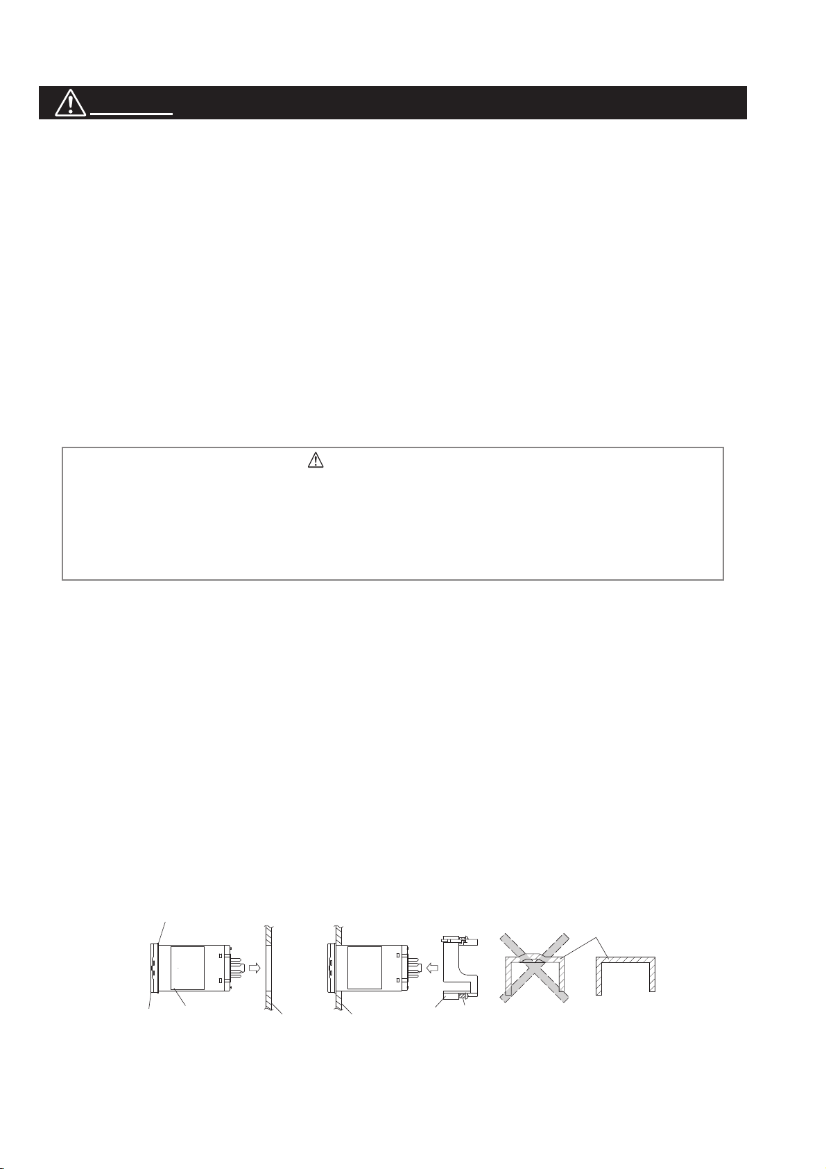
Insert the controller unit into the panel cutout from the front, and then put the mounting bracket from the rear.
The mounting bracket should be pushed in until the controller is securely fi xed to the panel. If there is a slight
gap remaining, gently tighten the two screws until the gap disappears. (Make sure not to over tighten the screws,
as doing so may result in the mounting bracket separating from the stopper.)
●
The front of this equipment is waterproof in compliance with NEMA-4X standards (IP66- equivalent). To effect
waterproof, the included packing is shall be attached between the controller and the panel according to the
guidelines below. (Incorrect attachment may cause the equipment to lose its waterproof capabilities.)
(1) As shown in Fig. 1, insert to the panel after attaching the packing to the equipment case.
(2) As shown in Fig. 2, tighten the screws of the mouthing bracket so that no gaps can remain between the
equipment face, the packing and the panels. Once fi nished, confi rm that there are no changes in shape such
as displaced or improperly-fi tted packing, etc. as shown in Fig. 3
< Attachment on vertical surface (Horizontal attachment) >
Packing
Fig. 2Fig. 1
UnitUnit
Fig. 3
Packing
Case
Front
●
If the panel does not have enough strength, gaps may develop between the packing and the panel to lose
Case
PanelPanel
Mounting
bracket
Screw
Case
(Bad)
(Good)
waterproofi ng capabilities.
●
In order to aid heat dissipation, do not block the sides of the equipment.
4
Page 6
●
Do not block the air vents on the top and bottom of the case.
Wiring
●
For thermocouple input, use the designated compensation lead; for RTD input, use wires with small lead wire
resistance and without any resistance difference among the three wires.
●
To avoid noise conductor effects, input signal wires should be separated from electric power lines or load lines.
●
Input signal wire and output signal wire should be separated each other. And both should be shield wire.
●
If there is a lot of noise from the power source, adding an insulation transducer and using a noise fi lter is
recommended. Always attach a noise fi lter to a panel that is grounded securely, and keep the wiring between
the noise fi lter output side and the measuring equipment power terminal wiring to a minimum length. Please do
not attach fuses and switches, etc. to the noise fi lter output wiring; otherwise the fi lter’s effectiveness will be
decreased.
●
Twisting the power wires is effective when connecting the wires. (The shorter the pitch of the twist, the more
effective the connection is against noise.)
●
Operation preparation time is required for the contact output when power is turned on. If using it as a signal to an
external interlock circuit, please couple it with a delayed relay.
Concerning the output relay, connecting the maximum rated load will shorten the product’s life; so please attach
an auxiliary relay. If the output operation frequency is high, selecting a SSR drive output type is recommended.
[Proportionate cycles] Relay output: 30 seconds or more, SSR drive output:
1 second or more
●
When inductive loads such as magnetic opening/closing equipment, etc. as relay output equipment are connected,
use of a surge absorber is recommended in order to protect the contacts against opening/closing surges and to
ensure long-term use.
Recommended specifi cation for the surge absorber
Voltage Nominal varistor voltage
100V 240V
200V 470V
Attachment position: between the relay control output contacts.
Operation
●
The alarm function does not work properly when an error takes place unless the settings are made correctly.
Always verify its setting before operation.
●
If the input wiring breaks, the display will read “UUUU” or “LLLL”. When replacing the sensor, always turn the
power OFF.
Others
●
Please do not wipe the equipment with organic solvents such as alcohol or benzene, etc. If wiping is necessary,
use a neutral cleaning agent.
●
Do not use mobile phones near this equipment (within 50 cm). Otherwise a malfunction may result.
●
Trouble may occur if the equipment is used near a radio, TV, or wireless device.
●
This equipment should be treated as an industrial waste when it is disposed of.
5
Page 7

Contents
Safety Instructions ................................................................................................................... 1
WARNING .................................................................................................................................................. 2
Installation and wiring
Maintenance
Caution ......................................................................................................................................................4
Installation
Panel mounting
Wiring
Operation
Others
............................................................................................................................................ 3
............................................................................................................................................... 4
..................................................................................................................................................... 5
................................................................................................................................................ 5
..................................................................................................................................................... 5
For Proper Use ........................................................................................................................ 8
Model Specifi cations................................................................................................................ 9
1 Part names and functions ................................................................................................ 10
1-1 Operation keys..................................................................................................................................... 10
1-2 Indicators ............................................................................................................................................. 11
1-3 Digital characters ................................................................................................................................. 12
.............................................................................................................................. 2
........................................................................................................................................ 4
2 Basic Operation ............................................................................................................... 13
2-1 Basic operation .................................................................................................................................... 13
2-2 Changing SV (Set value) .....................................................................................................................14
2-3 Parameters List.................................................................................................................................... 15
Operation Mode
1st block parameter
2nd block parameter
3rd block parameter
2-4 Temperature control functions ............................................................................................................. 19
2-5 Communication function ...................................................................................................................... 19
..................................................................................................................................... 15
................................................................................................................................ 15
...............................................................................................................................16
................................................................................................................................ 18
3 Parameter functions and setting procedure ..................................................................... 20
3-1 1st block parameter .............................................................................................................................20
[MANU] Manual mode selection (001)
[Stby] Standby setting (002)
[PRoG] Ramp soak control (004)
[LACH] Alarm latch cancel (005)
[At] Auto-tuning (006)
[tM1] [tM2] Timer 1 display (007), Timer 2 display (008)
[AL1] [A1-L] [A1-H] Alarm 1 settings (010, 011, 012)
[AL2] [A2-L] [A2-H] Alarm 2 settings (013, 014, 015)
[LoC] Key lock (019)
.................................................................................................................... 21
............................................................................................................................ 25
............................................................................................................................. 29
.................................................................................................... 20
............................................................................................................. 22
............................................................................................................ 24
.......................................................................... 27
.............................................................................. 28
.............................................................................. 28
6
Page 8

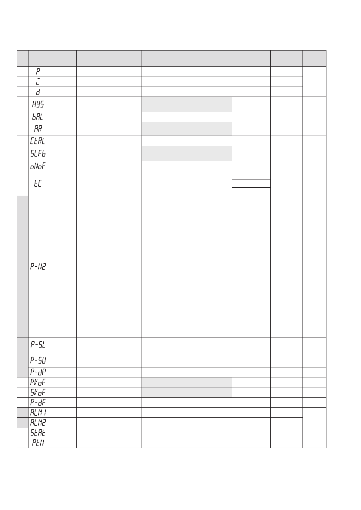
3-2 2nd block parameter ............................................................................................................................ 30
[P] Proportional band (030)
[i] Integral time (031)
[d] Derivative time (032)
[HyS] Hysteresis range for ON/OFF control (033)
[bAL] Output convergence value (036)
[AR] Anti-reset windup (037)
[CtRL] Control algorithm (038)
[SLFb] PV (Process variable) stable range (039)
[oNoF] Hysteresis mode (040)
[tC] Cycle time of control output 1 (041)
[P-N2] Input signal code (043)
[P-SL] Lower limit of measuring range (044)
[P-SU] Upper limit of measuring range (045)
[P-dP] Decimal point position (046)
[PVOF] PV offset (048)
[SVOF] SV shift (049)
[P-dF] Time constant of input fi lter (050)
[ALM1] [ALM2] Alarm type 1, 2 (051, 052)
[StAt] Status display of ramp soak (054)
[PtN] Ramp soak execution pattern (055)
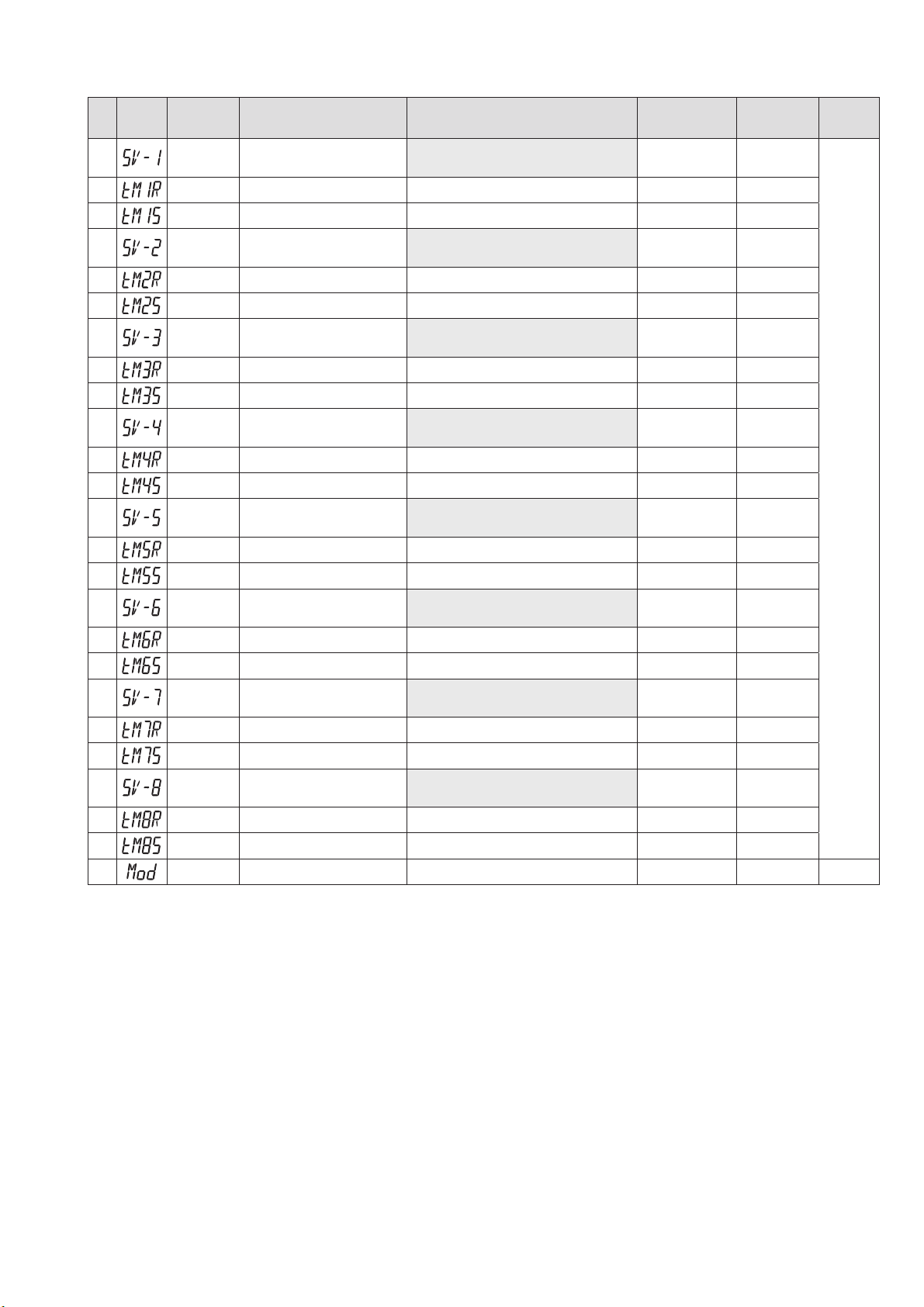
[SV-1] to [SV-8] 1st target SV to 8th target SV (056 to 077)
[tM1R] to [tM8R] 1st ramp time to 8th ramp time (057 to 078)
[tM1S] to [tM8S] 1st soak time to 8th soak time (058 to 079)
[Mod] Ramp soak mode (080)
..................................................................................................................... 30
............................................................................................................................. 30
........................................................................................................................ 30
..................................................................................... 32
.................................................................................................... 34
.................................................................................................................. 35
............................................................................................................... 36
....................................................................................... 39
................................................................................................................. 40
.................................................................................................. 41
................................................................................................................ 42
............................................................................................ 43
............................................................................................ 43
......................................................................................................... 45
.......................................................................................................................... 46
............................................................................................................................ 47
.................................................................................................. 48
............................................................................................ 49
.................................................................................................. 51
................................................................................................. 52
....................................................................... 53
.................................................................. 53
..................................................................... 53
................................................................................................................. 55
3-3 3rd block parameter .............................................................................................................................57
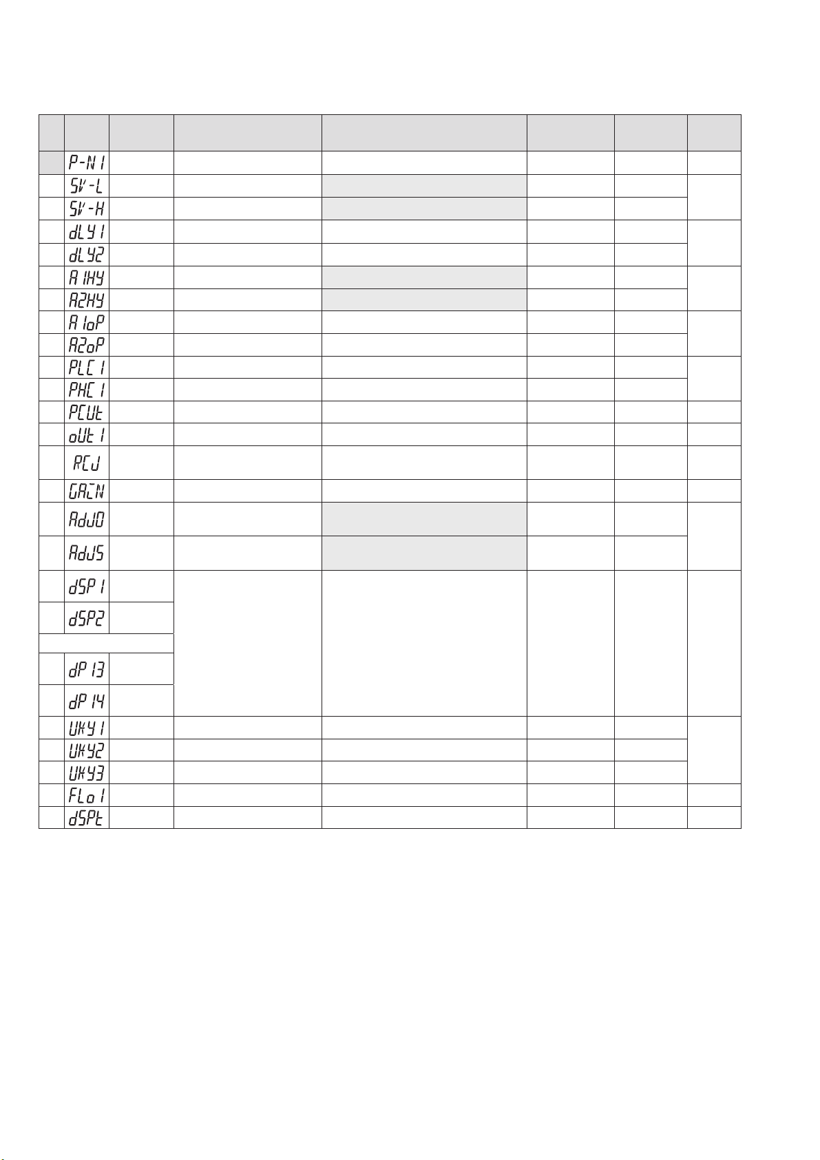
[P-N1] Control action (090)
[SV-L] SV (Set value) lower limiter (091)
[SV-H] SV (Set value) upper limiter (092)
[dLY1] [dLY2] Delay time 1, 2 (093, 094)
[A1Hy] [A2Hy] Alarm 1, 2 hysteresis (098, 099)
[A1oP] [A2oP] Alarm 1, 2 options (101, 102)
[PLC1] [PHC1] OUT1 Upper/Lower Limits (104, 105)
[PCUt] Output limit types (108)
[oUt1] Output value (MV) display (109)
[RCJ] RCJ (Cold junction compensation) setting (111)
[AdJ0] User-defi nable zero adjustment (113)
[AdJS] User-defi nable span adjustment (114)
[dSP1] to [dP14] Parameter mask (126 to 139)
[UKy1] [UKy2] [UKy3] USER key assignment (143, 144, 145)
[FLo1] MV1 during FALT (146)
[dSPt] PV/SV display OFF (148)
.................................................................................................................... 57
................................................................................................ 58
................................................................................................ 58
................................................................................................ 59
...................................................................................... 59
........................................................................................... 61
............................................................................. 62
............................................................................................................... 63
.................................................................................................. 64
.............................................................................. 65
............................................................................................ 66
............................................................................................ 66
.......................................................................................... 68
................................................................. 70
.............................................................................................................. 71
............................................................................................................. 72
4 Troubleshooting ............................................................................................................... 73
7
Page 9
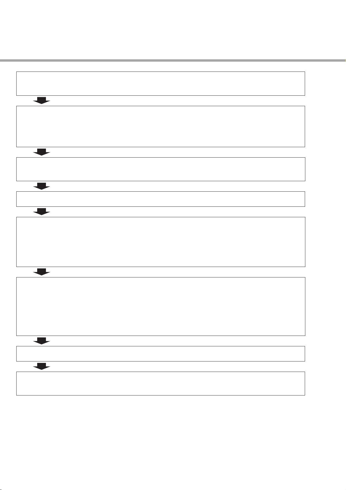
For Proper Use
Confi rmation of model
code
Installation and Mounting External dimensions
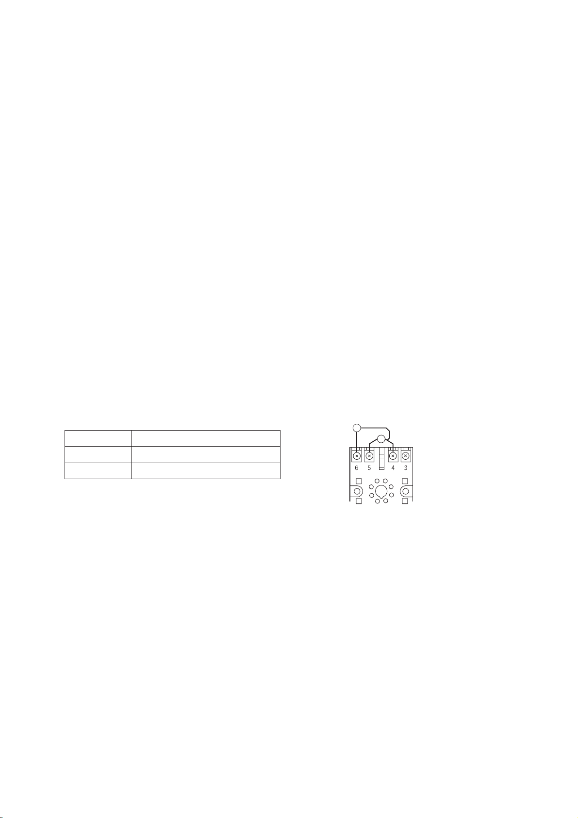
Wiring Terminal connection diagram
Power ON
Before starting operation, wait for at least 30 minutes for the PXF to warm up.
Basic settings and
operation
Please confi rm that the model delivered matches your order.
“Model Specifi cations” (see page 9)
• Panel cutout
• Panel mounting dimensions
“4 Installation and Mounting” (instruction manual)
“5 Wiring” (instruction manual)
Basic operations (see page 13)
Changing SV (Set value) (see page 14)
Parameters List (see page 15 to 18)
Temperature control functions (see page 19)
Advanced Usage Setting of input sensor and input range (see page 42 to 44)
Selecting control method (see page 36)
Controlling through auto-tuning (see page 25)
Setting parameter automatically
• Fuzzy control (see page 37)
• Self tuning control (see page 37)
Operation
Error Indications Display during equipment error
“4 Troubleshooting” (see page 73)
8
Page 10
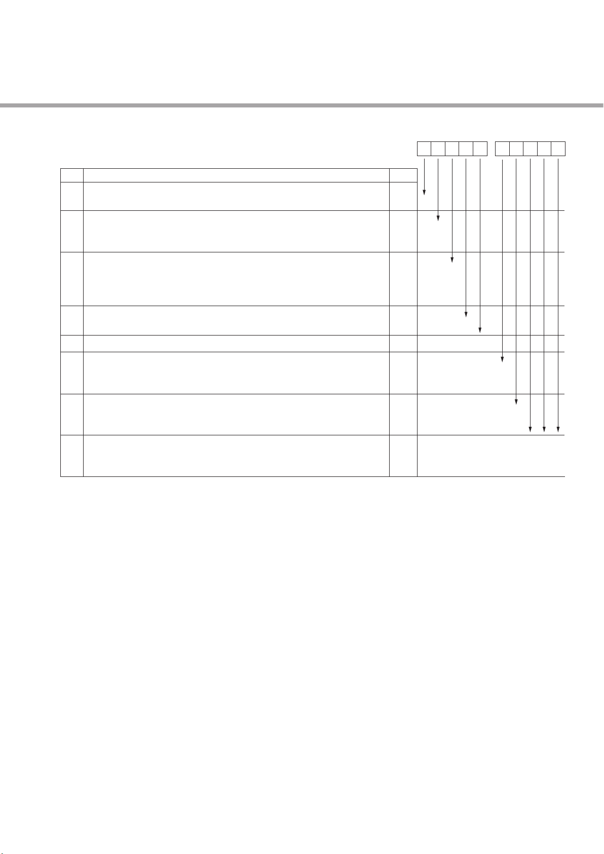
Model Specications
Digit
<Front panel size W × H>
4
48×48mm
<Input signal>
5
Universal input (Thermocouple/Volt, backwards compatible wiring)
Universal input (RTD/mA, backwards compatible wiring)
<Control output>
6
Relay contact (SPDT)
SSR drive output
Current output
<Terminal form>
7
Socket type
<Revision code>
8
<Alarm output>
9
None
2 points
<Power supply voltage>
10
100 to 240V AC
24 V AC/DC
11
12
13
Specifications
PXF
Note
Note1
456 7 8
4
A
N
B
C
E
U
9 10 11 12 13
-
2U
2
4
G
V
B
0Y 04
Y 0 0
Note1: Wiring compatible to previous PXZ, PXW, PXV and PXR socket controllers.
(mA input dose not require the resistor)
9
Page 11
1
This section describes the names and functions of each part of the front panel. The front panel has the PV and SV
displays, the status indicator lamps, and the setting keys, etc. Their functions are explained below. Please read and
understand them before using the PXF.
For details about the setting of parameters, see Chapter 2 and Chapter 3.
PXF4
Part names and functions
Operation keys Indicator
UP key
DOWN key
LEFT key
SEL key
USERkey
1-1 Operation keys
●
USER key
• Press to switch between SV and MV during the PV/SV display (operation mode).
• Press to return to the operation mode from the parameter setup mode.
• Press and hold the USER key to start the assigned function during the PV/SV display (operation mode). (No
function is allocated at the factory.)
●
SEL key
• Press to enter the parameter setup mode from the operation mode or standby.
• Press to fi nish selecting and save change.
●
LEFT key
• Press to move the digit when you editing the numerals.
●
UP/DOWN key
• Press to change the SV during the PV/SV display.
• Press to switch the parameters during the parameter selection mode.
• Press to change the parameter value during the parameter editing mode.
●
USER+UP keys, USER+DOWN keys
• By pressing and holding the USER key and the UP/DOWN key during the PV/SV display, you can start the
assigned function.
In the factory default setting, the USER + UP key allows you to switch between run/standby, and the USER +
DOWN key to switch between start/stop of auto-tuning.
See page 70 for how to change the setting of these keys.
10
Page 12

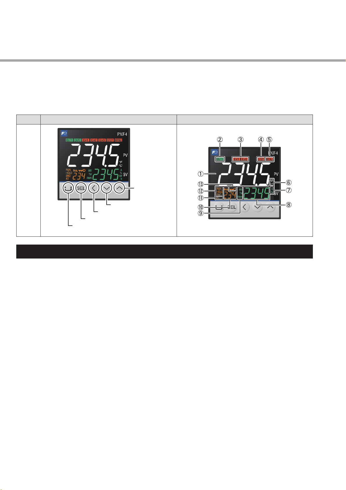
Indicators
1-2 Indicators
(1) Process variable (PV)
Indicates the process variable. In the parameter setup mode, the parameter name is displayed.
(2) OUT1 indicator
Lights during control output is ON.
(3) EV1, EV2 indicators
Lights during digital output 1 to 2 are ON.
(4) STBY indicator
Lights when the stanby is set to ON. (see page 21)
(5) MANU indicator
Lights during manual mode. (see page 20)
(6) °C/˚F indicator
Shows the temperature unit under use.
(7) A, % indicator
Indicates the unit applied to the value on SV screen during the parameter selection mode and parameter editing
mode.
(8) Set Value (SV) / Manipulated variable (MV)
Shows the setpoint or the manipulated variable. During the parameter editing mode, the parameter setpoint is
displayed.
(9) MV indicator
Lights when the MV is displayed.
(10) Screen No.
Shows screen No. when in parameter setting.
(11) AT indicator
Lights during auto tuning. (see page 25)
(12) RUN/HOLD/END indicators
Lights during ramp soak operation. (see page 22)
(13) KEYLOCK indicator
Lights when the keylock is on. (see page 29)
11
Page 13
Part names and functions
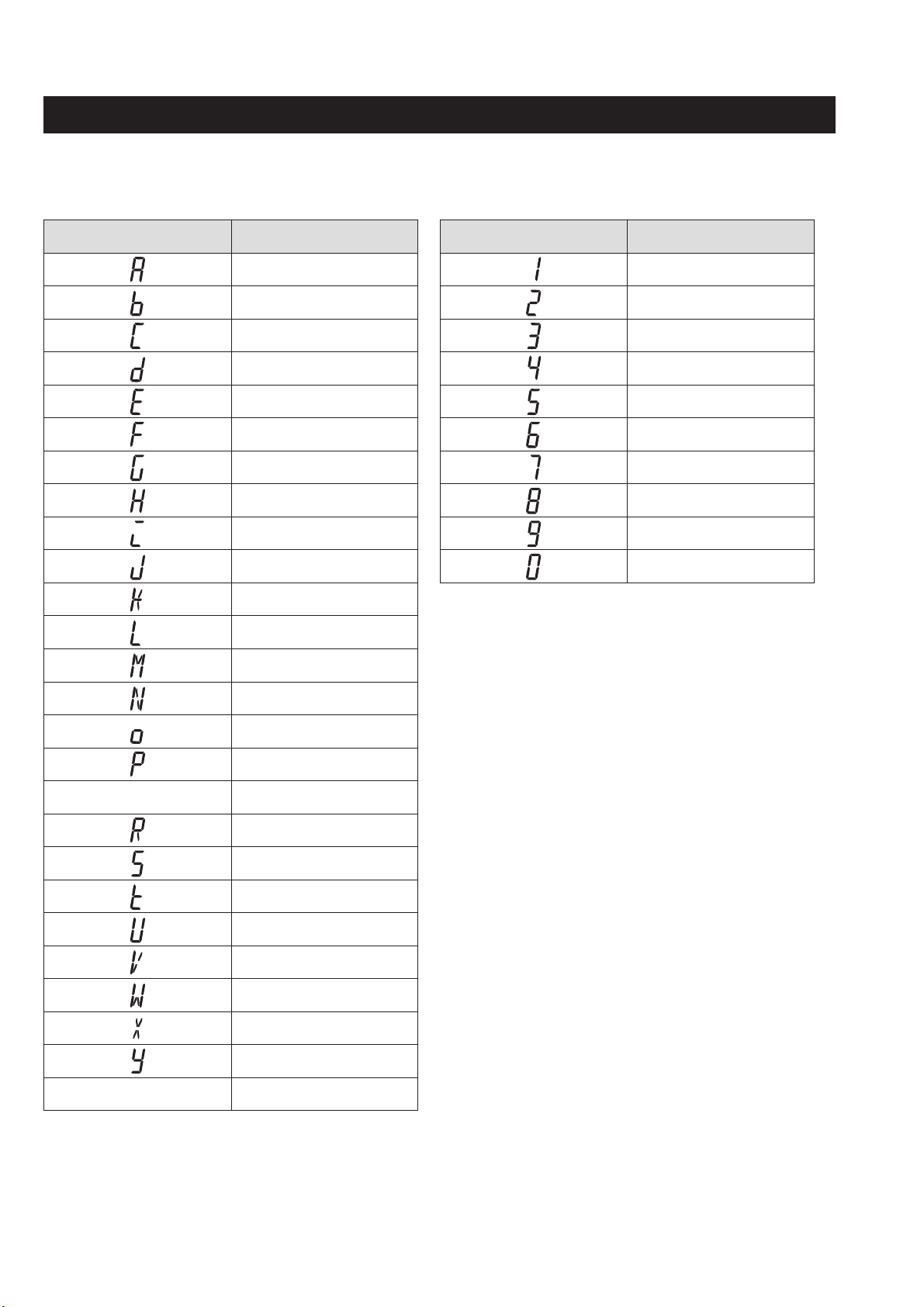
1-3 Digital characters
The following tables provide correspondence between digital characters used for the display of the controller and
alphanumerical characters. (See the following table for details.)
Digital character Alphabet Digital character Numer
A 1
B 2
C 3
D 4
E 5
F 6
G 7
H 8
―
I 9
J 0
K
L
M
N
O
P
Q
R
S
T
U
V
―
W
X
Y
Z
12
Page 14
2
Basic Operation
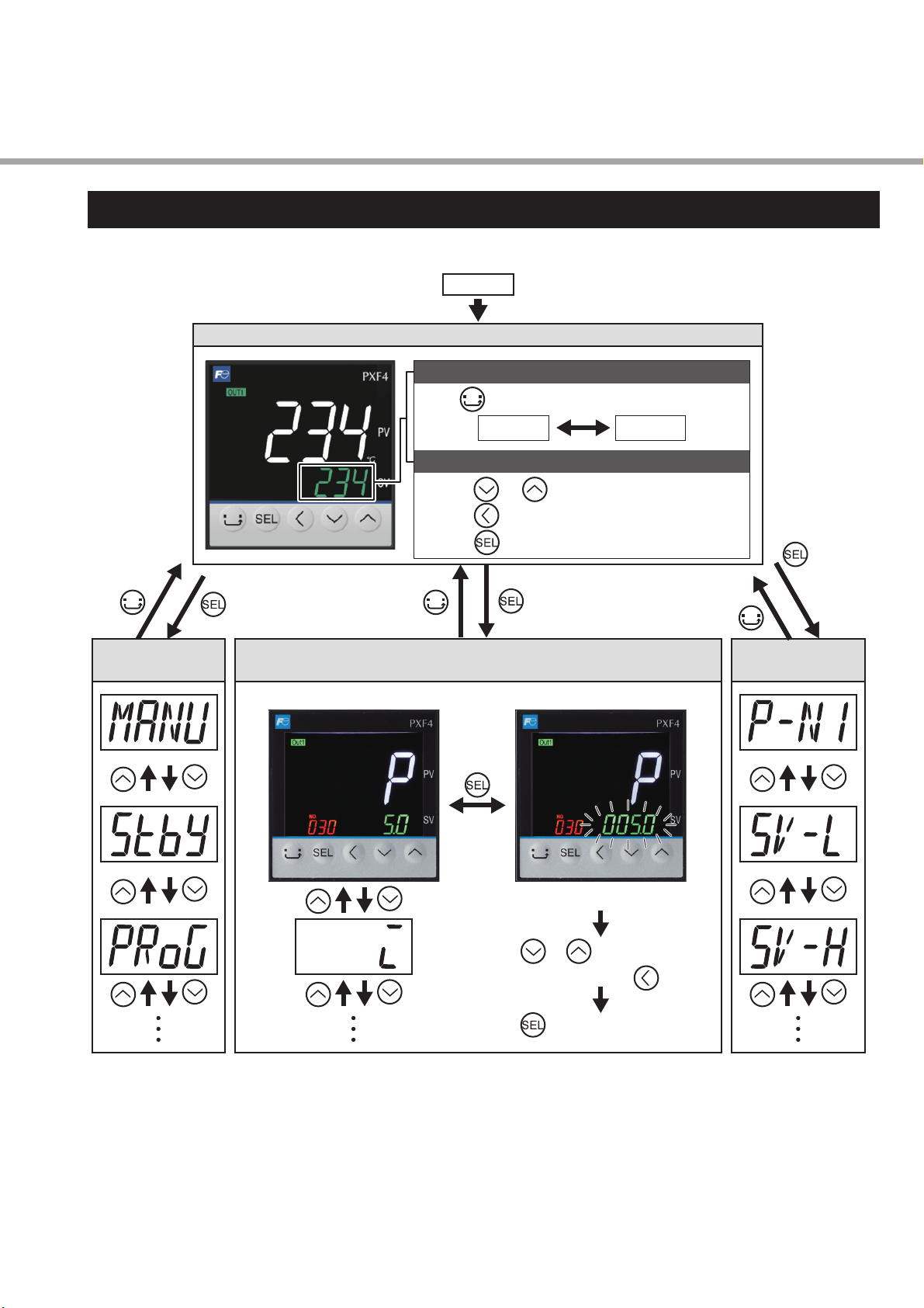
2-1 Basic operation
The below fi gure illustrates the mode transition and the key operations.
Power ON
Operation Mode
To switch between SV and MV
Press .
1st block
parameter
SV
To change the setpoint
Ɣ3UHVV or to change the value.
Ɣ3UHVV to move to the next digit.
Ɣ3UHVV to move to the next digit.
approx.
1 second
2nd block parameter
< Parameter selection mode > < Parameter editing mode >
approx.
3 seconds
MV
approx.
5 seconds
3rd block
parameter
The parameter setpoint starts blinking.
Press or to change the value.
To change the digit, use .
Press to resist the changed value.
13
Page 15
Basic Operation
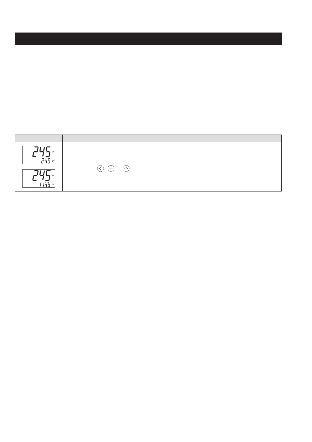
2-2 Changing SV (Set value)
[Description] –––––––––––––––––––––––––––––––––––––––––––––––––––––––
The SV is a target value for control.
●
SV must be within the range between [SV-L] (lower limit) and [SV-H] (upper limit) which belong to Pid
parameter.
Related parameters:
●
SV (Set value) lower limiter [SV-L], SV (Set value) upper limiter [SV-H] (see page 58)
[Setting example] Changing the SV from 250°C to 1195°C –––––––––––––––––––
Display Operating procedure
1. Check that the PV/SV display is shown.
1.
Press , or keys to change SV to “1195”.
2.
The change become effective immediately.
➔
14
Page 16
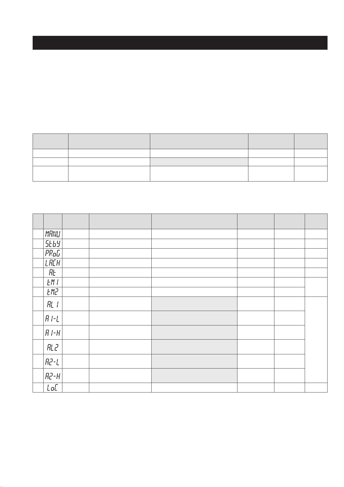
Parameters List
2-3 Parameters List
The following explains each channel parameter.
●
The range of the parameters in the shaded area indicates the industrial values.
When you change the PV input lower limit (P-SL), PV input upper limit (P-SU), or decimal place position (P-dP),
reconfi gure all the industrial values.
●
Power-cycle the controller after you change the setpoint of the parameters of which No. column is shaded in gray.
Operation Mode
Parameter
symbol
PV
Process Value ―――
Parameter name Setting range
SV Set value Within the limit of 0 to 100% of FS
MV Manipulated Variable (%) -5.0 to 105.0 (%)
Factory default
setting
(°C)
0
-5.0
1st block parameter
No Display
1
2 Stby Standby setting oFF, oN oFF DSP1-1
4 PRoG Ramp soak control oFF, RUN, HLd oFF DSP1-2
5 LACH Alarm latch cancel oFF, RSt oFF DSP1-4
6 At Auto-tuning oFF, oN, L-oN oFF DSP1-8
7 tM-1 Timer 1 display ――DSP1-16
8 tM-2 Timer 2 display ――DSP1-32
10
11 A1-L Lower limit value of alarm 1
12
13
14
15
19
Parameter
symbol
MANU
AL1 Set value of alarm 1
A1-H Upper limit value of alarm 1
AL2 Set value of alarm 2
A2-L Lower limit value of alarm 2
A2-H Upper limit value of alarm 2
LoC Key lock 0 to 5 0 DSP3-1
Parameter name Setting range
Manual mode selection oFF, oN oFF DSP13-32
Absolute value alarm: 0 to 100%FS
Deviation alarm: -100 to 100%FS
Absolute value alarm: 0 to 100%FS,
Deviation alarm: -100 to 100%FS
Absolute value alarm: 0 to 100%FS
Deviation alarm: -100 to 100%FS
Absolute value alarm: 0 to 100%FS
Deviation alarm: -100 to 100%FS
Absolute value alarm: 0 to 100%FS
Deviation alarm: -100 to 100%FS
Absolute value alarm: 0 to 100%FS
Deviation alarm: -100 to 100%FS
Factory
default setting
10 (°C)
10 (°C)
10 (°C)
10 (°C)
10 (°C)
10 (°C)
Parameter
mask DSP
DSP1-128
DSP2-1
DSP2-2
DSP2-4
DSP2-8
DSP2-16
Parameter
mask DSP
―
DSP14-
32768
Reference
page
20
21
22
24
25
27
28
29
15
Page 17
Basic Operation
2nd block parameter
No Display
30 P Proportional band 0.0 to 999.0 (%) 5.0 DSP3-2
31 i Integral time 0 to 3200 (sec) 240 DSP3-4
32
33
36 bAL Output convergence value -100.0 to 100.0 (%) 0.0 DSP3-128
37 AR Anti-reset windup 0 to 100%FS 400 (°C) DSP4-1
38 CtRL Control algorithm
39 SLFb
40 oNoF Hysteresis mode oN, oFF oN DSP4-8
41 tC
43
44 P-SL
45 P-SU
46
48 PVOF PV offset -10.00 to 10.00%FS 0 (°C) DSP5-8
49 SVOF SV shift -50.00 to 50.00%FS 0 (°C) DSP5-16
50 P-dF Time constant of input fi lter 0.0 to 120.0 (sec) 5.0 DSP5-32
51 ALM1 Alarm type 1 0 to 31 0 DSP5-64
52 ALM2 Alarm type 2 0 to 31 0 DSP5-128
54
55 PtN
Parameter
symbol
d Derivative time 0.0 to 999.9 (sec) 60.0 DSP3-8
HyS
P-N2 Input signal code
P-dP Decimal point position 0 to 3 0 DSP5-2
StAt Status display of ramp soak ――DSP6-2
Parameter name Setting range
Hysteresis range for ON/
OFF control
PV (Process variable) stable
range
Cycle time of control output 1
Lower limit of measuring
range
Upper limit of measuring
range
Ramp soak execution pattern
0 to 50%FS 1 (°C) DSP3-16
oNoF, Pid, FUZY, SELF, Pid2
0 to 100%FS 8 (°C) DSP4-4
1 to 150 (sec)
JPt (Resistance bulb (RTD) JPt100)
Pt (Resistance bulb (RTD) Pt100)
J (Thermocouple J)
K (Thermocouple K)
R (Thermocouple R)
b (Thermocouple B)
S (Thermocouple S)
t (Thermocouple T)
E (Thermocouple E)
L (Thermocouple L)
N (Thermocouple N)
PL-2 (Thermocouple PL-II)
W (Thermocouple W)
0-5V (DC voltage 0 to 5V DC)
1-5V (DC voltage 1 to 5V DC)
0-10 (DC voltage 0 to 10V DC)
2-10 (DC voltage 2 to 10V DC)
0-20 (Direct current 0 to 20mA)
4-20 (Direct current 4 to 20mA)
U (Thermocouple U)
MV (MV)
-1999 to 9999 0 (°C) DSP4-128
-1999 to 9999 400 (°C) DSP5-1
1 to 3 1 DSP6-4
Factory
default setting
Pid DSP4-2
Relay: 30
SSR: 2
Current: 1
K DSP4-64
Parameter
mask DSP
DSP4-16
Reference
page
30
32
34
35
36
39
40
41
42
43
45
46
47
48
49
51
52
16
Page 18
Parameters List
No Display
56 SV-1 1st target SV
57 tM1R 1st ramp time 0.00 to 99.59 0:00 DSP6-16
58
59
60
61
62
63
64
65
66
67
68
69
70
71
72
73
74
75
76
77
78
79
80
Parameter
symbol
tM1S 1st soak time 0.00 to 99.59 0:00 DSP6-32
SV-2 2nd target SV
tM2R 2nd ramp time 0.00 to 99.59 0:00 DSP6-128
tM2S 2nd soak time 0.00 to 99.59 0:00 DSP7-1
SV-3 3rd target SV
tM3R 3rd ramp time 0.00 to 99.59
tM3S 3rd soak time 0.00 to 99.59
SV-4 4th target SV
tM4R 4th ramp time 0.00 to 99.59
tM4S 4th soak time 0.00 to 99.59
SV-5 5th target SV
tM5R 5th ramp time 0.00 to 99.59
tM5S 5th soak time 0.00 to 99.59
SV-6 6th target SV
tM6R 6th ramp time 0.00 to 99.59
tM6S 6th soak time 0.00 to 99.59
SV-7 7th target SV
tM7R 7th ramp time 0.00 to 99.59
tM7S 7th soak time 0.00 to 99.59
SV-8 8th target SV
tM8R 8th ramp time 0.00 to 99.59
tM8S 8th soak time 0.00 to 99.59
Mod Ramp soak mode 0 to 15
Parameter name Setting range
SV lower limit (SV-L) to
SV upper limit (SV-H) %FS
SV lower limit (SV-L) to
SV upper limit (SV-H) %FS
SV lower limit (SV-L) to
SV upper limit (SV-H) %FS
SV lower limit (SV-L) to
SV upper limit (SV-H) %FS
SV lower limit (SV-L) to
SV upper limit (SV-H) %FS
SV lower limit (SV-L) to
SV upper limit (SV-H) %FS
SV lower limit (SV-L) to
SV upper limit (SV-H) %FS
SV lower limit (SV-L) to
SV upper limit (SV-H) %FS
Factory
default setting
0 (°C) DSP6-8
0 (°C) DSP6-64
0 (°C) DSP7-2
0:00
0:00
0 (°C) DSP7-16
0:00
0:00
0 (°C) DSP7-128
0:00
0:00
0 (°C) DSP8-4
0:00
0:00
0 (°C) DSP8-32
0:00
0:00
0 (°C) DSP9-1
0:00
0:00
0
Parameter
mask DSP
DSP7-4
DSP7-8
DSP7-32
DSP7-64
DSP8-1
DSP8-2
DSP8-8
DSP8-16
DSP8-64
DSP8-128
DSP9-2
DSP9-4
DSP9-8
Reference
page
53
55
17
Page 19
Basic Operation
3rd block parameter
No Display
90 P-N1 Control action 0 to 3
91 SV-L SV (Set value) lower limiter 0 to 100%FS 0 (°C) DSP9-32
92 SV-H SV (Set value) upper limiter 0 to 100%FS 400 (°C) DSP9-64
93
94 dLY2 Delay time 2 0 to 9999 (sec) 0 DSP10-1
98 A1Hy Alarm 1 hysteresis 0 to 50%FS 1 (°C) DSP10-16
99 A2Hy Alarm 2 hysteresis 0 to 50%FS 1 (°C) DSP10-32
101
102
104
105
108
109
111
112
113
114
Parameter
symbol
dLY1 Delay time 1 0 to 9999 (sec) 0 DSP9-128
A1oP Alarm 1 options 000 to 111 000 DSP10-128
A2oP Alarm 2 options 000 to 111 000 DSP11-1
PLC1 Lower limit for output 1 -5.0 to 105.0 (%) -5.0 DSP11-4
PHC1 Upper limit for output 1 -5.0 to 105.0 (%) 105.0 DSP11-8
PCUt Output limit types 0 to 3 0 DSP11-64
oUt1 Output value (MV) display ――DSP11-128
RCJ
GAiN PV gradient 0.001 to 2.000 1.000 DSP12-4
AdJ0
AdJS
Parameter name Setting range
RCJ (Cold junction
compensation) setting
User-defi nable zero
adjustment
User-defi nable span
adjustment
oN, oFF oN DSP12-2
-50 to 50%FS 0 (°C) DSP12-8
-50 to 50%FS 0 (°C) DSP12-16
Factory
default setting
0
Parameter
mask DSP
DSP9-16
Reference
page
57
58
59
59
61
62
63
64
65
―
66
126
127
138
139
143
144
145
146
148
dSP1
dSP2
…
dP13
dP14
UKy1 USER key 0 to 6 0 DSP14-8
UKy2 USER key + UP key 0 to 6 1 DSP14-16
UKy3 USER key + DOWN key 0 to 6 5 DSP14-32
FLo1 MV1 during FALT -5.0 to 105.0 (%) -5.0 DSP14-64
dSPt PV/SV display OFF 0 to 8 0 DSP14-256
Parameter mask ―
Depends on
the model
DSP14-128
68
70
71
72
18
Page 20
Temperature control functions
2-4 Temperature control functions
This controller has fi ve types of temperature control function. Select according to type and use.
Temperature control
functions
ON/OFF (2-position)
control
PID control
Fuzzy control
Self tuning control
PID2 control
You can set the temperature control function in the parameter [CtRL] (see page 36).
Switches output control ON/OFF according to the SV/PV magnitude relationship.
Control systems can be built from simple elements such as SSR. This is appropriate
for situations where high accuracy is not required.
PID calculation and controls proceed according to the previously set PID parameters.
PID parameters can be set manually or through auto-tuning ([AT]).
It is the most basic control in this equipment.
Reduces the amount of overshoot during control. It is effective when you want to
suppress overshoot while changing SV, even during processes where it may take a
long time to reach the target value.
Adds controls while automatically calculating PID to meet the control target or
changing SV. It is effective when the control conditions change frequently.
Suppresses the amount of overshoot during control for processes that turn the control
target off and then on again. It is effective when the control target turns on and off
while power fl ows continuously to the temperature controller.
Description
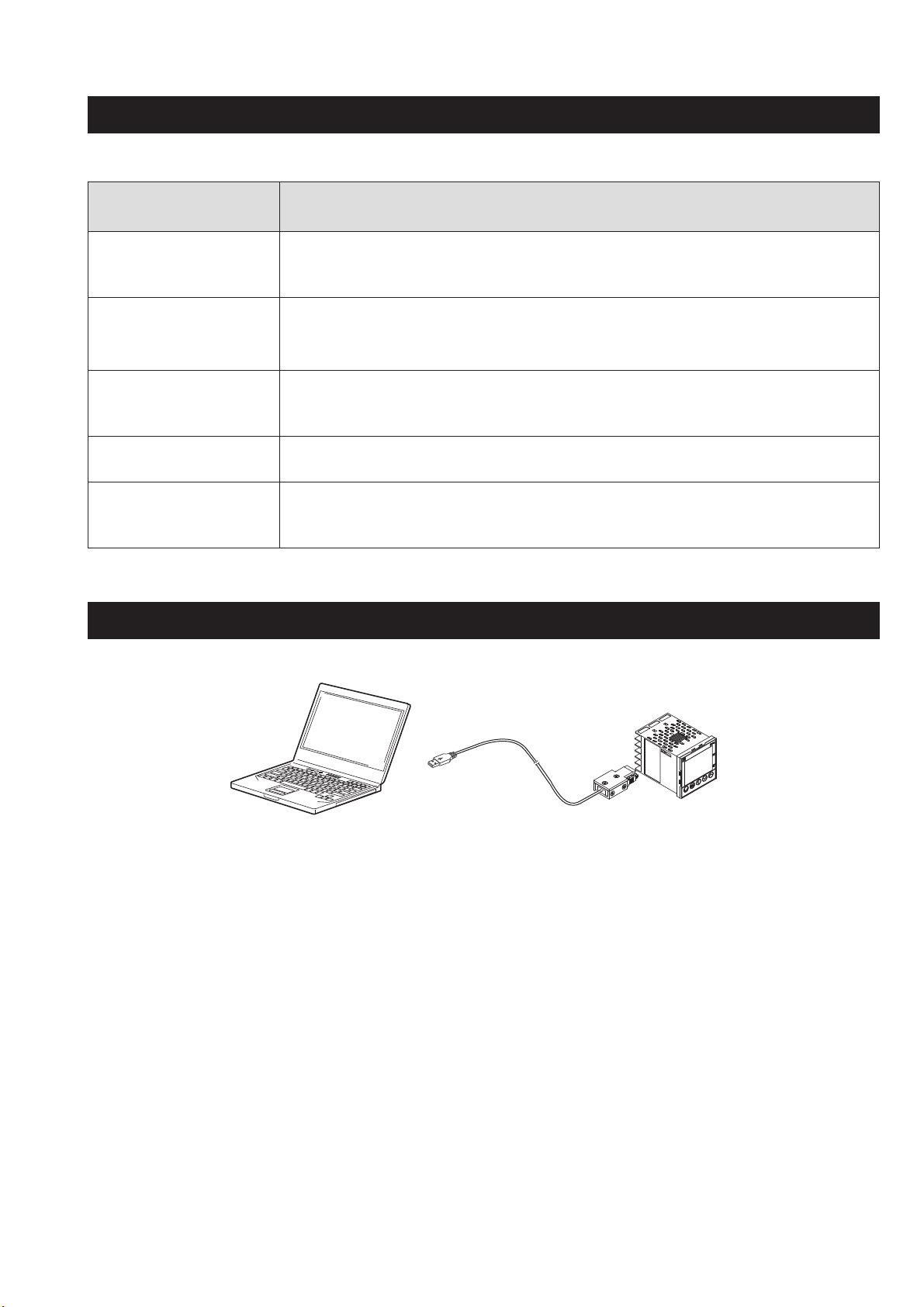
2-5 Communication function
This controller has the interface for the dedicated cable which allows data transmission with a PC.
Personal
computer
PC loader communication cable
19
Page 21
3
Parameter functions and setting procedure
3-1 1st block parameter
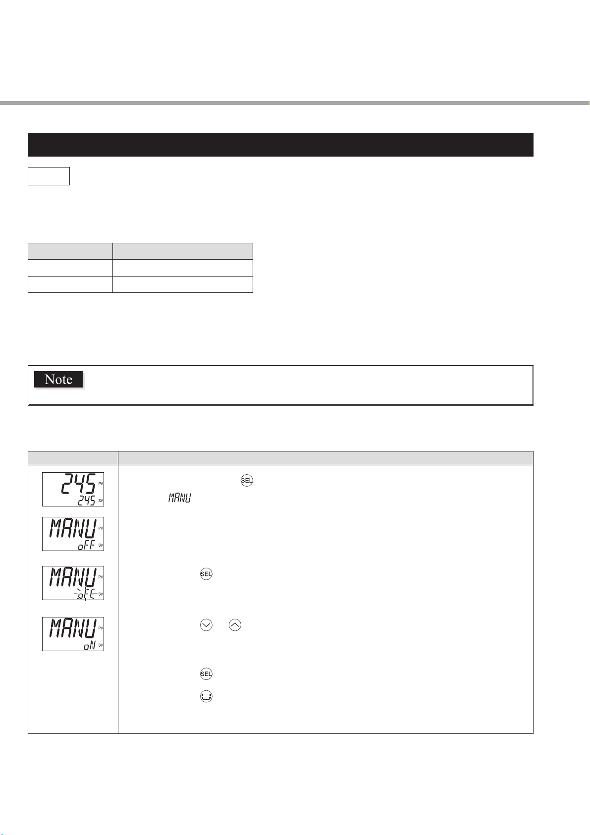
MANU
Manual mode selection (001)
[Description] –––––––––––––––––––––––––––––––––––––––––––––––––––––––
Allows you to select how to set the manipulated variable, automatically or manually.
Setpoint
oFF
oN
●
MANU indicator lights during manual operation. (see page 11)
●
In this screen, only the switchover between auto/manual is available. Manual operation of control output is
available on PV/MV screen.
This parameter is not displayed in default setting. To use this parameter, change the
setting of the parameter “Parameter mask” (see page 68).
Description
Automatically
Manually
[Setting example] Changing the mode from Auto to Manual –––––––––––––––––
Display Operating procedure
Press and hold the key for about one second during the SV/PV display.
1.
appears.
➔
Press the key.
2.
The setpoint starts blinking.
➔
Press the or keys to change “ oFF ” to “ oN .”
3.
Press the key or wait for three seconds to save the change.
4.
Press the key.
5.
The screen returns to the SV/PV display.
➔
20
Page 22
1st block parameter
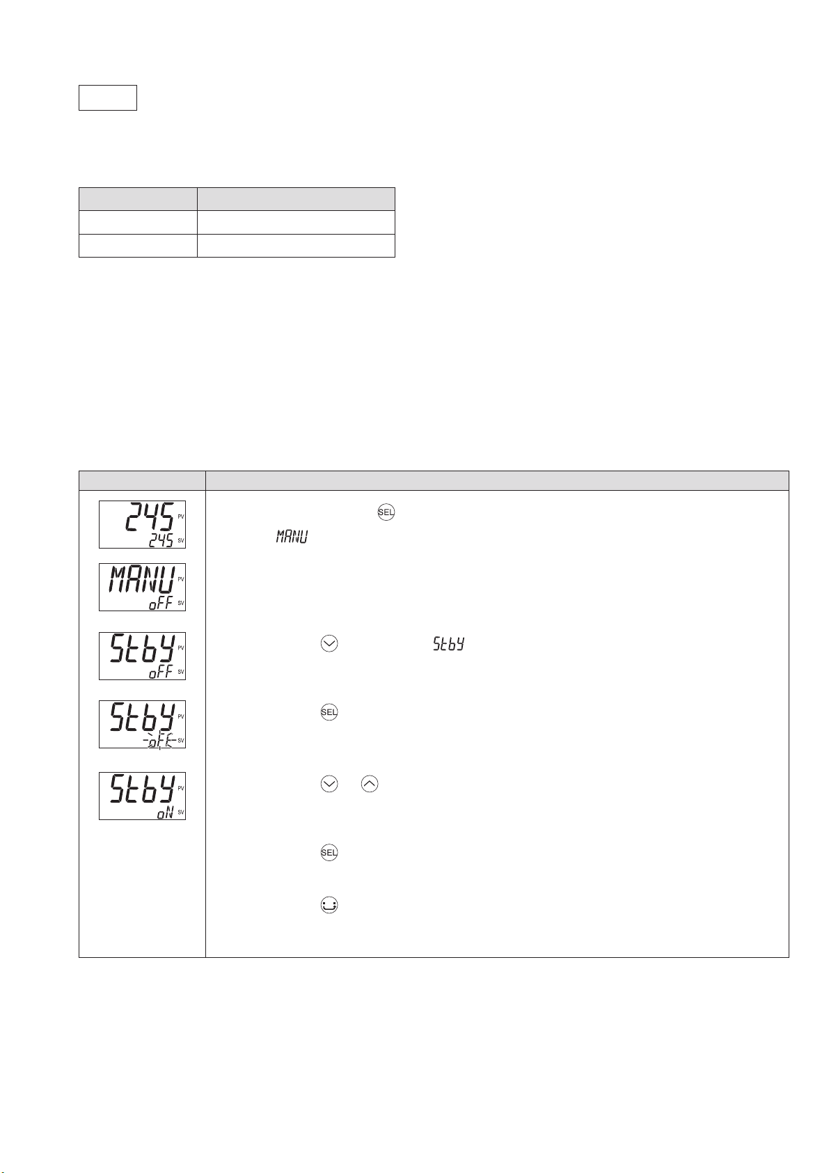
Stby
Standby setting (002)
[Description] –––––––––––––––––––––––––––––––––––––––––––––––––––––––
Allows you to switch between run and standby.
Setpoint
oFF
oN
●
STBY indicator lights during stanby. (see page 11)
●
When hold alarms is on, the hold function activates when you switch the standby setting from “ oN ” to “ oFF .”
●
If the instrument is put into standby during auto tuning, the auto tuning is canceled. To complete auto-tuning, turn
standby setting “ oFF ” and restart auto tuning.
●
When the controller switches to standby mode, the ON delay timer will be reset. It will begin again when standby
setting is turned off.
Description
Operation mode
Standby mode
[Setting example] Switching to Standby mode ––––––––––––––––––––––––––––
Display Operating procedure
Press and hold the key for about one second during the SV/PV display.
1.
appears.
➔
Press the key to display .
2.
Press the key.
3.
The setpoint starts blinking.
➔
Press the or keys to change “ oFF ” to “ oN .”
4.
Press the key or wait for three seconds to save the change.
5.
Now the controller is in the standby mode.
➔
Press the key.
6.
The screen returns to the SV/PV display.
➔
21
Page 23
Parameter functions and setting procedure
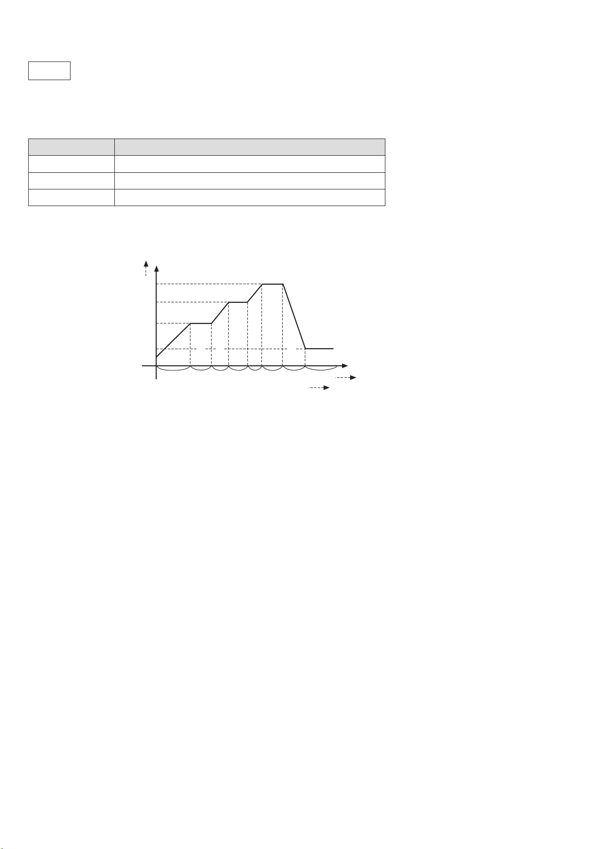
PRoG
Ramp soak control (004)
[Description] –––––––––––––––––––––––––––––––––––––––––––––––––––––––
Allows you to switch between Ramp soak states.
Second ramp
First soak
Description
Second soak
Third ramp
Third soak
Fourth ramp
Up to tM8R
Setpoint
oFF
RUN
HLd
●
This function automatically changes the SV (Set value) according to the program pattern set in advance as shown
Ramp soak is stopped.
Ramp soak starts.
Ramp soak hold. To release the hold, select “ RUN ” again.
in the following line graph. Up to eight pairs of rampsoak operation can be programmed.
Up to SV-8
SV-3
SV-2
SV-1
SV-4
PV
First ramp Fourth soak
tM1S tM2S tM3S tM4S Up to tM8S
tM1R tM2R tM3R tM4R
Ramp : the section in which the SV changes toward the target value.
Soak : the section in which the SV is the target value, and remains unchanged.
●
The fi rst ramp starts at the PV that is the one just before running the program.
●
By setting the Ramp soak mode parameter [Mod] to “power-on start,” you can make the controller start with the
ramp soak program (Power-on starting function).
●
The parameter information changes automatically depending on the ramp soak state.
• “ ENd ” (end): Ramp soak has fi nished.
●
During ramp soak operation, one of RUN, HOLD, or END indicators light according to the state of ramp soak.
(see page 11)
●
During ramp soak operation, on-going step No. and “ r ” (ramp) or “ - ” (soak) are displayed on the screen No.
area of operation screen (PV/SV screen).
For example, “ 2r ” appears during step 2 ramp, and “ 2- ” during step 2 soak.
Related parameters:
• Status display of ramp soak [StAt] (see page 51)
• Ramp soak execution pattern [PtN] (see page 52)
• 1st target SV to 8th target SV [SV-1] to [SV-8] (see page 53)
• 1st ramp time to 8th ramp time [tM1R] to [tM8R] (see page 53)
• 1st soak time to 8th soak time [tM1S] to [tM8S] (see page 53)
• Ramp soak mode [Mod] (see page 55)
22
Page 24

1st block parameter
[Setting example] Starting the ramp soak program ––––––––––––––––––––––––
Display Operating procedure
Press and hold the key for about one second during the SV/PV display.
1.
appears.
➔
Press the key to display .
2.
Press the key.
3.
The setpoint starts blinking.
➔
Press the or keys to change “ oFF ” to “ RUN .”
4.
Press the key or wait for three seconds to save the change.
5.
The ramp soak program starts.
➔
Press the key.
6.
The screen returns to the SV/PV display.
➔
23
Page 25

Parameter functions and setting procedure
LACH
Alarm latch cancel (005)
[Description] –––––––––––––––––––––––––––––––––––––––––––––––––––––––
Allows you to cancel the alarm latch.
Setpoint
oFF
RSt
keeps the latch on
releases latch
Description
[Setting example] Unlatching the alarm –––––––––––––––––––––––––––––––––
Display Operating procedure
Press and hold the key for about one second during the SV/PV display.
1.
appears.
➔
Press the key to display .
2.
Press the key.
3.
The setpoint starts blinking.
➔
Press the or keys to change “ oFF ” to “ RSt .”
4.
Press the key or wait for three seconds to save the change.
5.
The alarm is unlatched.
➔
Press the key.
6.
The screen returns to the SV/PV display.
➔
24
Page 26

1st block parameter
Auto-tuning (006)
At
[Description] –––––––––––––––––––––––––––––––––––––––––––––––––––––––
Running auto-tuning automatically sets the optimal PID.
Setpoint
oFF
oN
L-oN
●
There are the following two types in auto-tuning.
Stops or fi nishes the auto-tuning.
Starts the normal auto-tuning.
Starts the low-PV auto-tuning.
Normal type
Performs ON/OFF operation with SV as the baseline to
calculate PID.
Low-PV type
Perfoms ON/OFF operation with SV-10% to calculate PID.
Use this setting if you want to prevent overshoot.
Description
Process
Value
SV
Process
Value
SV
AT start
AT calculating
PV
AT start
AT calculating
PID
Control
t
SV-10%FS
PV
●
AT indicator lights during auto-tuning. (see page 11)
●
When auto tuning is normally completed, the automatically set PID parameter value is maintained even if the
PID
Control
t
power is turned off. If the power is turned off during auto tuning, the auto-tuning function is invalidated with PID
parameters unchanged. In such a case, start again from the beginning.
●
Since ON-OFF operation (2-position operation) is performed during auto tuning, PV may fl uctuate greatly
depending on the process. Do not perform auto tuning for the processes where large fl uctuation of PV is not
allowed. Do not perform auto tuning, either, for the processes where the response is quick, such as pressure
control or fl ow rate control.
●
If auto tuning does not end after 4 hours, it means that tuning may not be completed successfully. Check input/
output wiring and parameters such as control output (forward, reverse) and input sensor type.
●
Carry out the auto-tuning again when:
• you change SV,
• you change PV input type, or
• operation does not work properly due to the change in operating conditions.
●
You can run auto-tuning when the control type is set to “ FUZY ” or “ Pid2 .” (see page 36)
●
You cannot run auto-tuning during manual mode. (see page 20)
●
When you are using the PID selection function, the auto-tuning result for the selected PID group is stored.
●
Auto tuning is forcibly terminated when SV is changed by the ramp soak function, remote SV function, or ramp
SV.
Since ON/OFF control is performed during auto-tuning, overshoot against the SV
may occur. To reduce the overshoot, execute the auto-tuning with “ L-oN ” (Low PV).
Related parameters: [CtRL] (see page 36)
25
Page 27

Parameter functions and setting procedure
[Setting example] Running Auto-tuning –––––––––––––––––––––––––––––––––
Display Operating procedure
Press and hold the key for about one second during the SV/PV display.
1.
appears.
➔
Press the key to display .
2.
Press the key.
3.
The setpoint starts blinking.
➔
Press the or keys to change “ oFF ” to “ oN .”
4.
Press the key or wait for three seconds to save the change.
5.
The normal auto-tuning starts.
➔
Press the key.
6.
The screen returns to the SV/PV display.
➔
26
Page 28

1st block parameter
tM1
tM2
Timer 1 display (007), Timer 2 display (008)
[Description] –––––––––––––––––––––––––––––––––––––––––––––––––––––––
Displays the remaining time of the timer 1 and the timer 2.
●
The remaining time of the ON/OFF-delay timer is counted down. When the counter shows “ 0 ,” the alarm relay
is closed.
●
During count-down, if the PV changes to the value of the temperature at which the alarm is set to OFF, the
counter is reset, and the alarm relay is opened.
Related parameters:
• Alarm 1, 2 hysteresis [A1Hy], [A2Hy] (see page 59)
• Delay time 1, 2 [dLy1], [dLy2] (see page 59)
[Setting example] Checking the remaining time on the timer 1 –––––––––––––––
Display Operating procedure
Press and hold the key for about one second during the SV/PV display.
1.
appears.
➔
Press the key to display .
2.
The remaining time on the timer 1 appears.
➔
Press the key to display .
3.
The remaining time on the timer 2 appears.
➔
Press the key.
4.
The screen returns to the SV/PV display.
➔
27
Page 29

Parameter functions and setting procedure
AL1 A1-L A1-H
AL2
A2-L A2-H
Alarm 1 settings (010, 011, 012)
Alarm 2 settings (013, 014, 015)
[Description] –––––––––––––––––––––––––––––––––––––––––––––––––––––––
Allows you to set the alarm setpoint.
●
AL1, AL2
●
A1-L, A2-L
●
A1-H, A2-H
Absolute value alarm: 0 to 100%FS
Deviation alarm: -100 to 100%FS
●
When the alarm type ([ALM1], [ALM2]) is set to 0 to 15, you can set the alarm 1, 2 ([AL1], [AL2]).
●
When the alarm type ([ALM1], [ALM2]) is set to any value other than 0 to 15, you can set the upper and lower
limits of alarm 1, 2 ([A1-H], [A2-H] and [A1-L], [A2-L]).
Related parameters:
• Alarm type 1, 2 [ ALM1], [ALM2] (see page 49)
• Alarm 1, 2 hysteresis [A1Hy], [A2Hy] (see page 59)
• Delay time 1, 2 [dLy1], [dLy2] (see page 59)
• Alarm 1, 2 options [A1oP], [A2oP] (see page 61)
: Alarm
: Low-limit alarm
: High-limit alarm
Setting range
[Setting example] Setting the alarm 1 to “ 20 ” ––––––––––––––––––––––––––––
Display Operating procedure
Press and hold the key for about one second during the SV/PV display.
1.
appears.
➔
Press the key to display .
2.
Press the key.
3.
The setpoint starts blinking.
➔
Press the , or keys to change “ 10 ” to “ 20 .”
4.
Press the key or wait for three seconds to save the change.
5.
Press the key.
6.
The screen returns to the SV/PV display.
➔
28
Page 30

1st block parameter
LoC
Key lock (019)
[Description] –––––––––––––––––––––––––––––––––––––––––––––––––––––––
Prevents SV parameters from being changed.
Setpoint
0
1
2
3
4
5
●
When the keylock is set to 1, 2, 4, or 5, the KEYLOCK indicator lights. (see page 11)
●
You can view the parameters regardless of the keylock setting.
Unlocked (reset)
All settings are unchangeable from the controller, but changeable via communication.
Only the SV is changeable from the controller, and all settings are changeable via communication.
All settings are changeable from the controller, but unchangeable via communication.
All settings are unchangeable from the controller or via communication.
Only the SV is changeable from the controller, but all settings are unchangeable via communication.
Description
[Setting example] Changing the keylock setting to 2 –––––––––––––––––––––––
Display Operating procedure
Press and hold the key for about one second during the SV/PV display.
1.
appears.
➔
Press the key to display .
2.
Press the key.
3.
The setpoint starts blinking.
➔
Press the key to change “ 0 ” to “ 2 .”
4.
Press the key or wait for three seconds to save the change.
5.
Keylock is activated.
➔
Press the key.
6.
The screen returns to the SV/PV display.
➔
29
Page 31

Parameter functions and setting procedure
3-2 2nd block parameter
Proportional band (030)
P
Integral time (031)
i
Derivative time (032)
d
[Description] –––––––––––––––––––––––––––––––––––––––––––––––––––––––
Allows you to set PID (Proportional Band, Integration Time, Differential Time).
Setting range
P: 0.0 to 999.9%
i: 0 to 3200 seconds
d: 0.0 to 999.9 seconds
●
The following control methods are available with PID settings.
ON/OFF control
(2-position control)
PID control
PI control
P control
When [P] = “ 0 ” or the control method [CtRL] is set to “ oNoF ,” ON/OFF control is
used. Use this function when you want to run simple control without worrying about the
controllability.
Use this function when you want to control with high controllability.
[P], [i], and [d] should be adjusted to optimal values for the control target, although Pid
can be activated by setting the control method [CtRL] to “ Pid ,” and [P] ≠ “ 0.0 ,” [i] ≠ “ 0 ,”
[d] ≠ “ 0.0 .”
In normal situations, run auto-tuning to optimally adjust P, I, and D before using this
function.
When the control method [CtRL] is set to “ Pid ” and [P]≠“ 0.0 ”, [i]≠“ 0 ”, [d]=“ 0.0 ,” D
control is turned off and PI control is used.
When the control method [CtRL] is set to “ Pid ” and [P]≠“ 0.0 ”, [i]=“ 0 ”, [d]=“ 0.0 ,”
I and D controls are turned off and P control is used. In principle, P control generates
offset and PV does not agree with SV. In this case, adjust the output convergence value
[bAL].
●
Running auto-tuning automatically sets the optimal PID. (see page 25)
●
The PID settings confi gured by auto-tuning are generally considered to be optimal settings. If you want to change
the responsiveness, adjust PID manually.
●
Generally, control becomes unstable when [P] is set too small. On the other hand, setting it too big makes the
response slow.
●
If you set [P] to “ 0.0 ,” the control method parameter [CtRL] automatically turn to “ oNoF. ”
●
Set the hysteresis for the ON/OFF (2-position) control with the parameter [HyS]. (see page 32)
Related parameters: Control algorithm [CtRL] (see page 36)
Do not perform auto tuning during ON/OFF control.
30
Page 32

2nd block parameter
[Setting example] Setting P = 10.0%, I = 100sec, D = 20sec –––––––––––––––––
Display Operating procedure
Press and hold the key for about three seconds during the SV/PV display.
1.
appears.
➔
Press the key.
2.
The setpoint starts blinking.
➔
Press the , or keys to change “ 5.0 ” to “ 10.0 .”
3.
Press the key or wait for three seconds to save the change.
4.
The setpoint is set to “ 10.0 .”
➔
Press the key to display .
5.
Press the key.
6.
The setpoint starts blinking.
➔
Press the or keys to change “ 240 ” to “ 100 .”
7.
Press the key or wait for three seconds to save the change.
8.
The setpoint is set to “ 100 .”
➔
Press the key to display .
9.
Press the key.
10.
The setpoint starts blinking.
➔
Press the or keys to change “ 60.0 ” to “ 20.0 .”
11.
Press the key or wait for three seconds to save the change.
12.
Press the key.
13.
The screen returns to the SV/PV display.
➔
31
Page 33

Parameter functions and setting procedure
HyS
Hysteresis range for ON/OFF control (033)
[Description] –––––––––––––––––––––––––––––––––––––––––––––––––––––––
If you set the control method parameter [CtRL] to “ oNoF ,” set the hysteresis for on/off control in this parameter.
Setting range
0 to 50%FS
●
The controllability varies with the size of the hysteresis.
●
Small hysteresis
Large hysteresis
●
The relationship between SV and hysteresis in normal and reverse operation is shown below.
Reverse
Process
Value
SV
High-precision control
●
Frequency of output relays is high, so lifespan becomes short.
●
Low-precision control
●
Frequency of output relays is low, so lifespan is relatively long.
Normal
PV
HYS
Process
Value
SV
PV
HYS
t
PV<SV
Control
Output
●
During ON/OFF control, the [i] and [d] settings do not affect control.
●
If the hysteresis width is narrow, and PV and SV are nearly equal, the output may frequently switch on and off.
ON
OFF
PV>SV
Control
Output
ON
OFF
PV>SV
PV<SV
Note that it may affect the life of the contact.
Related parameters: Control algorithm [CtRL] (see page 36)
t
32
Page 34

2nd block parameter
[Setting example] Changing the hysteresis range from 25%FS to 30%FS ––––––
Display Operating procedure
Press and hold the key for about three seconds during the SV/PV display.
1.
appears.
➔
Press the key to display .
2.
Press the key.
3.
The setpoint starts blinking.
➔
Press the , or keys to change “ 25 ” to “ 30 .”
4.
Press the key or wait for three seconds to save the change.
5.
Press the key.
6.
The screen returns to the SV/PV display.
➔
33
Page 35

Parameter functions and setting procedure
bAL
Output convergence value (036)
[Description] –––––––––––––––––––––––––––––––––––––––––––––––––––––––
Output convergence value is a function that adds an offset to MV value.
Setting range
-100 to 100%
●
By this function, the [bAL] offset is added to original MV which is the result of PID calculation determined by
PV and SV, and the total value is emitted as MV.
(The factory default setting is 0%.)
MV
100%
bAL=0%
40%
Proportional
band
50%
SV
bAL=40%
PV
[Setting example] Changing Output convergence value from 0.0% to 3.0% –––––
Display Operating procedure
Press and hold the key for about three seconds during the SV/PV display.
1.
appears.
➔
Press the key to display .
2.
Press the key.
3.
The setpoint starts blinking.
➔
Press the , or keys to change “ 0.0 ” to “ 3.0 .”
4.
Press the key or wait for three seconds to save the change.
5.
Press the key.
6.
The screen returns to the SV/PV display.
➔
34
Page 36

2nd block parameter
AR
Anti-reset windup (037)
[Description] –––––––––––––––––––––––––––––––––––––––––––––––––––––––
Anti-reset windup is a function that limits the range of valid integration to control overshooting.
Setting range
0 to 100%FS
●
The anti-reset windup function ([AR]) disables the integration when the PV falls outside of the Ar set range that
is centered around SV. It is automatically set to the optimum value when auto-tuning is activated.
PV
SV
AR value
AR value
In this zone, the integration
is disabled.
In this zone, the integration
is carried out.
In this zone, the integration
is disabled.
t
[Setting example] Changing the anti-reset windup to 500°C –––––––––––––––––
Display Operating procedure
Press and hold the key for about three seconds during the SV/PV display.
1.
appears.
➔
Press the key to display .
2.
Press the key.
3.
The setpoint starts blinking.
➔
Press the , or keys to change “ 100 ” to “ 500 .”
4.
Press the key or wait for three seconds to save the change.
5.
Press the key.
6.
The screen returns to the SV/PV display.
➔
35
Page 37

Parameter functions and setting procedure
CtRL
Control algorithm (038)
[Description] –––––––––––––––––––––––––––––––––––––––––––––––––––––––
This controller has fi ve temperature control functions. Select the best control method for your application.
Setpoint
oNoF
Pid
FUZY
SELF
Pid2
ON/OFF (2-position) control
PID control
Fuzzy control
Self tuning control
PID2 control
(1) ON/OFF (2-position) control (oNoF)
When you set the control method [CtRL] to “ oNoF,” the device uses ON/OFF control.
In ON/OFF control, the controller switches the control output between ON (100%) and OFF (0%) according to the
SV/PV magnitude relationship. You can set the output hysteresis in the control parameters [HyS] (see page 32).
Reverse Operation (Heating)
Method used to control the electrical heating furnace. Set
the [HYS] to an appropriate value according to the control
target.
Description
Set value
SV
PV
HYS
Parameter Set value
CtRL oNoF
P-N1
2 or 3
HyS 0 to 50% FS (default: 1°C)
Normal operation (Cooling)
Method used to control the cooling machine.
Parameter Set value
CtRL oNoF
Control
output
Set value
ON
OFF
SV
PV<SV
PV>SV
PV
P-N1 0 or 1
HyS 0 to 50% FS (default: 1°C)
PV>SV
PV<SV
Control
output
ON
OFF
Notes
●
During ON/OFF control, the P, I and D settings do not affect control.
●
In the manual operation during ON/OFF control, MV displayed by pressing key is 100%, and MV
displayed by pressing
●
If the hysteresis width is narrow, and PV and SV are nearly equal, the output may frequently switch
key is 0%.
on and off. Note that it may affect the contact life.
Related parameters:
• Control action [P-N1] (see page 57)
• Hysteresis range for ON/OFF control [HyS] (see page 32)
t
HYS
t
36
Page 38

2nd block parameter
(2) PID control (Pid)
PID control starts when the parameter [CtRL] is “ Pid.” PID control calculate Pid and output the result according to
the set values of the parameters [P], [i], [d], and [AR]. (-5 to 105%)
Each parameter can be set either by manually tuning the values or by running auto-tuning ([AT]) to automatically
set the values.
Related parameters: Auto-tuning [At] (see page 25)
(3) Fuzzy control (FUZY)
This control minimizes the overshoot compared to normal PID. Fuzzy control can only be used after auto-tuning
has been activated and a PID set.
Related parameters: Auto-tuning [At] (see page 25)
(4) Self tuning control (SELF)
Adds controls while automatically calculating PID to meet the
Set value
control target or changing SV. Self-tuning is especially effective
for situations when a high level of control is not needed, but auto-
SV
tuning cannot be run due to frequent changes in the control target
conditions. If a high degree of control is required, select PID
control, fuzzy control or PID2 control.
●
The equipment will not be tuned properly if power is turned on
fi rst.
●
When redoing the self-tuning settings, fi rst set the control method
Dead time
to PID (“ Pid ”), and then set back to self-tuning.
Conditions where self-tuning can be used
●
When temperature rises right after the power is turned on
●
When temperature rises after SV change (or when the controller judges it necessary)
●
When the controller judges it necessary because the control has become unstable
Conditions where self-tuning cannot be used
●
During standby
●
During ON/OFF (2-position) control
●
During auto-tuning
●
During ramp soak operation
●
When input error occurs
●
When any of the [P], [i], [d], or [AR] parameters have been manually confi gured
●
During manual mode
●
During soft start
Tuning
t
Delay
Conditions where self-tuning is halted
●
When SV is changed (including when SV is changed by the ramp soak function, remote SV function, or ramp
SV.)
●
When self-tuning has not fi nished after running for nine or more hours
37
Page 39

Parameter functions and setting procedure
(5) PID2 control (Pid2)
This type of control reduces overshoot during control for processes that turn the control target off and then on again.
Set value
SV
Suppresses overshoot
PV
Controller power
Control loop
The algorithm used prevents over-integration of the PID calculations even while the control loop is still open.
PID2 control can only be used after auto-tuning has been activated and a PID set.
ON
OFF
Close Close
Open
t
[Setting example] Setting the control method to ON/OFF control –––––––––––––
Display Operating procedure
Press and hold the key for about three seconds during the SV/PV display.
1.
appears.
➔
Press the key to display .
2.
Press the key.
3.
The setpoint starts blinking.
➔
Press the or keys to change “ Pid ” to “ oNoF .”
4.
Press the key or wait for three seconds to save the change.
5.
The control method is set to ON/OFF control.
➔
Press the key.
6.
The screen returns to the SV/PV display.
➔
38
Page 40

2nd block parameter
SLFb
PV (Process variable) stable range (039)
[Description] –––––––––––––––––––––––––––––––––––––––––––––––––––––––
Self-tuning logic recognizes that control is stable if PV is staying within the SV ± [SLFb].
Setting range
0 to 100%FS
●
It is not necessary to set this parameter under normal conditions.
[Setting example] Changing the PV stable range from 2 to 3 –––––––––––––––––
Display Operating procedure
Press and hold the key for about three seconds during the SV/PV display.
1.
appears.
➔
Press the key to display .
2.
Press the key.
3.
The setpoint starts blinking.
➔
Press the , or keys to change “ 2.0 ” to “ 3.0 .”
4.
Press the key or wait for three seconds to save the change.
5.
Press the key.
6.
The screen returns to the SV/PV display.
➔
39
Page 41

Parameter functions and setting procedure
oNoF
Hysteresis mode (040)
[Description] –––––––––––––––––––––––––––––––––––––––––––––––––––––––
Selects the hysteresis operation during two-position control.
Setpoint
oFF
oN
Reverse
Normal
Operation
Performs two-position control with the range between [SV+HyS/2] and [SV-HyS/2].
Performs two-position control with the range between [SV, SV+HyS] and [SV, SV-HyS].
Setpoint: oFF Setpoint: oN
HyS
SV
HyS
SV
Description
HyS
SV
HyS
SV
[Setting example] Setting the hysteresis mode to OFF –––––––––––––––––––––
Display Operating procedure
Press and hold the key for about three seconds during the SV/PV display.
1.
appears.
➔
Press the key to display .
2.
Press the key.
3.
The setpoint starts blinking.
➔
Press the or keys to change “ oN ” to “oFF .”
4.
Press the key or wait for three seconds to save the change.
5.
Press the key.
6.
The screen returns to the SV/PV display.
➔
40
Page 42

2nd block parameter
Cycle time of control output 1 (041)
tC
[Description] –––––––––––––––––––––––––––––––––––––––––––––––––––––––
When using contact output and SSR drive output with PV input inside the
proportional band, output will switch between ON and OFF at regular intervals.
Setting range
1 to 150 sec
●
The following are the recommended settings for each control output.
The shorter the proportional cycle, the fi ner the control. However, shorter proportional cycles
Contact
output
SSR drive
output
also shorten the lifespan of the contact points and operating device. Keep a balance between
controllability and controller lifespan when adjusting the proportional cycles.
Approx.: 30 sec
Because there are no mechanical parts, use a short proportional cycle if the operating device is
working properly.
Approx.: 1 or 2 seconds
●
The proportional cycle for the current output is same as the blinking cycle of OUT
indicator (approximately 1 second).
Output ON
Proportional
cycle
Proportional
cycle
[Setting example] Setting OUT1 proportional cycle to 60 sec ––––––––––––––––
Display Operating procedure
Press and hold the key for about three seconds during the SV/PV display.
1.
appears.
➔
Press the key to display .
2.
Press the key.
3.
The setpoint starts blinking.
➔
Press the or keys to change “ 30 ” to “ 60 .”
4.
Press the key or wait for three seconds to save the change.
5.
Press the key.
6.
The screen returns to the SV/PV display.
➔
41
Page 43

Parameter functions and setting procedure
P-N2
Input signal code (043)
[Description] –––––––––––––––––––––––––––––––––––––––––––––––––––––––
Allows you to select PV input source from thermocouples, RTD, and others.
Setpoint
JPt
Pt
J
K
R
b
S
t
E
L
RTD JPt100
RTD Pt100
Thermocouple J
Thermocouple K
Thermocouple R
Thermocouple B
Thermocouple S
Thermocouple T
Thermocouple E
Thermocouple L
Description
Setpoint
N
PL-2
W
0-5V
1-5V
0-10
2-10
0-20
4-20
U
MV
Thermocouple N
Thermocouple PL-II
Thermocouple W
0 to 5 V DC
1 to 5 V DC
0 to 10 V DC
2 to 10 V DC
0 to 20 mA DC
4 to 20 mA DC
Thermocouple U
MV
Description
●
The connection to the terminal block differs with types of input (thermocouple/
RTD/voltage or current input). Check the Instruction Manual.
●
Power-cycle the controller after you change the input type setting.
[Setting example] Changing the input from thermocouple K to thermocouple R ––
Display Operating procedure
Press and hold the key for about three seconds during the SV/PV display.
1.
appears.
➔
Press the key to display
2.
Press the key.
3.
The setpoint starts blinking.
➔
Press the or keys to change “ K ” to “ R .”
4.
Press the key or wait for three seconds to save the change.
5.
Press the key.
6.
The screen returns to the SV/PV display.
➔
42
Page 44

2nd block parameter
P-SL
P-SU
Lower limit of measuring range (044)
Upper limit of measuring range (045)
[Description] –––––––––––––––––––––––––––––––––––––––––––––––––––––––
Allows you to set the upper/lower limit of PV input within the
measurement range.
Setting range
-1999 to 9999
●
Be sure to set the values so that [P-SU] is greater than [P-SL].
●
Be sure to set the values so that the subtraction of [P-SL] from [P-SU] is less than
10000 with no decimal point.
●
Measurement range
Minimum
increment
(°C)
0.1
0.1
0.1
0.1
0.1
0.1
0.1
0.1
0.1
0.1
0.1
0.1
0.1
0.1
1
0.1
0.1
0.1
1
0.1
0.1
0.1
1
1
1
Input type
RTD JPt100
RTD Pt100
Thermocouple
Thermocouple
J
K
Thermocouple R
Thermocouple B
[P-N2]
Measurement
Setpoint
0.0 to 150.0
0.0 to 300.0
0.0 to 500.0
JPt
0.0 to 600.0
-50.0 to 100.0
-100.0 to 200.0
-199.9 to 600.0
0.0 to 150.0
0.0 to 300.0
0.0 to 500.0
0.0 to 600.0
Pt
-50.0 to 100.0
-100.0 to 200.0
-199.9 to 600.0
-200 to 850.0
0.0 to 400.0
-20.0 to 400.0
J
0.0 to 800.0
-100 to 1000
0 to 400
-20.0 to 500.0
K
0.0 to 800.0
-200 to 1300
R 0 to 1700
b 0 to 1800
range
Scaling range
upper/lower limit
Input type
Thermocouple S
Thermocouple T
Thermocouple
Thermocouple
Thermocouple
E
L
N
Thermocouple
PL-II
Thermocouple W
DC voltage
DC0 to 5V
DC voltage
DC1 to 5V
DC voltage
DC0 to 10V
DC voltage
DC2 to 10V
Direct current
0-20mA
Direct current
4-20mA
Thermocouple
U
[P-N2]
Setpoint
S 0 to 1700
t
E
L -100 to 850
N -200 to 1300
PL-2 0 to 1300
W 0 to 2300
0-5V
1-5V
0-10
2-10
0-20
4-20
U
PV input
1200Υ
0Υ
Measurement
-199.9 to 200.0
-199.9 to 400.0
0.0 to 800.0
-150.0 to 800.0
-200 to 800
-1999 to 9999
(Scaling is
possible)
-199.9 to 400.0
-200 to 400
range
1000Υ
200Υ
Minimum
increment
(°C)
1
0.1
0.1
0.1
0.1
1
1
1
1
1
―
0.1
1
43
Page 45

Parameter functions and setting procedure
[Setting example]
Display Operating procedure
Setting the PV input upper limit to 1000°C and lower limit to 200°C
Press and hold the key for about three seconds during the SV/PV display.
1.
appears.
➔
Press the key to display .
2.
Press the key.
3.
The setpoint starts blinking.
➔
Press the or keys to change “ 0 ” to “ 200 .”
4.
Press the key or wait for three seconds to save the change.
5.
––
Press the key to display .
6.
Press the key.
7.
The setpoint starts blinking.
➔
Press the , or keys to change “ 400 ” to “ 1000 .”
8.
Press the key or wait for three seconds to save the change.
9.
Press the key.
10.
The screen returns to the SV/PV display.
➔
44
Page 46

2nd block parameter
P-dP
Decimal point position (046)
[Description] –––––––––––––––––––––––––––––––––––––––––––––––––––––––
Sets the decimal point position for the PV.
Setpoint
0
1
2
3
●
Two decimal places and three decimal places are available only when the input is voltage or current.
●
If you change the setting from numerals without decimal point to numerals with decimal point, the measurement
range setting ([P-SL], [P-SU]) is limited to the range from -199.9°C through 999.9°C.
For example, if you make the above change when the range is from 0 through 1300°C, the range will become the
one from 0.0 through 999.9°C.
No digit after decimal point
1 digit after decimal point
2 digits after decimal point
3 digits after decimal point
Description
One decimal place
Two decimal places
Three decimal places
[Setting example] Setting the PV display with one decimal place –––––––––––––
Display Operating procedure
Press and hold the key for about three seconds during the SV/PV display.
1.
appears.
➔
Press the key to display .
2.
Press the key.
3.
The setpoint starts blinking.
➔
Press the key to change “ 0 ” to “ 1 .”
4.
Press the key or wait for three seconds to save the change.
5.
Press the key.
6.
The screen returns to the SV/PV display.
➔
45
Page 47

Parameter functions and setting procedure
PVOF
PV offset (048)
[Description] –––––––––––––––––––––––––––––––––––––––––––––––––––––––
This function shifts PV input before display.
This function can be used to make the SV correspond with other
instruments.
Setting range
-10.00 to 10.00%FS
●
This controller operates at the displayed PV (the value to which the PV
offset value is added).
PV display
100°C
95°C
Before
shift
After
shift
0
Input
PV Shift of -5°C
[Setting example] Setting the PV input shift to -5.0°C ––––––––––––––––––––––
Display Operating procedure
Press and hold the key for about three seconds during the SV/PV display.
1.
appears.
➔
Press the key to display .
2.
Press the key.
3.
The setpoint starts blinking.
➔
Press the key to change “ 0 ” to “ -5 .”
4.
Press the key or wait for three seconds to save the change.
5.
Press the key.
6.
The screen returns to the SV/PV display.
➔
46
Page 48

2nd block parameter
SVOF
SV shift (049)
[Description] –––––––––––––––––––––––––––––––––––––––––––––––––––––––
This function specifi es the SV shift. This is used to eliminate remaining offset when using P control.
Setting range
-50.00 to 50.00%FS
●
Controls act on the calculated SV with SV offset.
●
Alarm determination acts on the displayed SV without SV offset.
[Setting example] Setting the SV shift to 7°C –––––––––––––––––––––––––––––
Display Operating procedure
Press and hold the key for about three seconds during the SV/PV display.
1.
appears.
➔
Press the key to display .
2.
Press the key.
3.
The setpoint starts blinking.
➔
Press the or keys to change “ 0.0 ” to “ 7.0 .”
4.
Press the key or wait for three seconds to save the change.
5.
Press the key.
6.
The screen returns to the SV/PV display.
➔
47
Page 49

Parameter functions and setting procedure
P-dF
Time constant of input fi lter (050)
[Description] –––––––––––––––––––––––––––––––––––––––––––––––––––––––
This low-pass fi lter function reduces noise and signal
fl uctuation.
Setting range
0.0 to 120.0 sec
●
If the input fi lter time constant is set to 5 and input is changed
from 0 to 100%, the PV display gradually changes, and it takes
about 5 seconds for the value to change from 0 to 63.2%, as
shown in the right fi gure.
X
Input
filter
㸣
100
63
(%)
Y
Approx.
5 sec
PID
Control
output
Input
PV display
t
The factory setting for input fi lter time constant is 5%.
Do not change this value unless absolutely necessary.
[Setting example] Setting the PV input fi lter time constant to 10 seconds –––––––
Display Operating procedure
Press and hold the key for about three seconds during the SV/PV display.
1.
appears.
➔
Press the key to display .
2.
Press the key.
3.
The setpoint starts blinking.
➔
Press the , or keys to change “ 5.0 ” to “ 10.0 .”
4.
Press the key or wait for three seconds to save the change.
5.
Press the key.
6.
The screen returns to the SV/PV display.
➔
48
Page 50

2nd block parameter
ALM1 ALM2
Alarm type 1, 2 (051, 052)
[Description] –––––––––––––––––––––––––––––––––––––––––––––––––––––––
Set the alarm type for Alarm1, Alarm2.
1-point alarm
Type
Absolute
value alarm
Deviation
alarm
Zone alarm
Setpoint
Alarm type Action diagram
No alarm ―
0
High alarm
1
Low alarm
2
High alarm (with hold)
3
Low alarm (with hold)
4
High alarm
5
Low alarm
6
High/Low alarm
7
High alarm (with hold)
8
Low alarm (with hold)
9
High/Low alarm (with
10
hold)
High/Low deviation
11
alarm
PV
ALn
PV
ALn
PV
ALn
PV
ALn
PV
SV
PV
SV
PV
SV
PV
SV
PV
SV
PV
SV
PV
SV
ALn
ALn
ALn
ALn
ALn
ALn
t
t
t
t
t
t
ALn
t
2-point alarm
t
t
t
High/Low
t
limit alarm
Zone alarm
Type
Setpoint
16
17
18
19
20
21
22
23
24
25
26
27
28
29
30
31
Alarm type Action diagram
High/Low absolute alarm
High/Low deviation
PV
PV
alarm
High absolute/Low
PV
deviation alarm
High deviation/Low
PV
absolute alarm
High/Low absolute alarm
PV
(with hold)
High/Low deviation
PV
alarm (with hold)
High absolute/Low
PV
deviation alarm (with hold)
High deviation/Low
PV
absolute alarm (with hold)
High/Low absolute alarm
High/Low deviation
PV
PV
alarm
High absolute/Low
PV
deviation alarm
High deviation/Low
PV
absolute alarm
High/Low absolute alarm
PV
(with hold)
High/Low deviation
PV
alarm (with hold)
High absolute/Low
PV
deviation alarm (with hold)
High deviation/Low
PV
absolute alarm (with hold)
An-H
An-L
An-H
An-L
An-H
An-L
An-H
An-L
An-H
An-L
An-H
An-L
An-H
An-L
An-H
An-L
An-H
An-L
An-H
An-L
An-H
An-L
An-H
An-L
An-H
An-L
An-H
An-L
An-H
An-L
An-H
An-L
●
ALn: indicates the alarm set values (AL1 to AL2)
●
An-H: indicates the alarm set values (A1-H to A2-H)
●
An-L: indicates the alarm set values (A1-L to A2-L)
What is alarm with hold?
The alarm will not turn ON immediately when the
process value gets into the alarm band and enters again.
PV (process value)
Lower limit alarm
Power on
Lower limit alarm
Lower limit alarm
(with hold)
Power off
off offoff
off off
Power on
on
output area
on
on
49
Page 51

Parameter functions and setting procedure
●
When alarm action code is changed, alarm set value may also become different
from previous settings.
●
Power-cycle the controller after you change the alarm type.
[Setting example]
Setting the type of the alarm 1 to “upper limit deviation alarm with hold” ––––––––
Display Operating procedure
Press and hold the key for about three seconds during the SV/PV display.
1.
appears.
➔
Press the key to display .
2.
Press the key.
3.
The setpoint starts blinking.
➔
Press the , or keys to change “ 0 ” to “ 8 .”
4.
Press the key or wait for three seconds to save the change.
5.
Press the key.
6.
The screen returns to the SV/PV display.
➔
50
Page 52

2nd block parameter
StAt
Status display of ramp soak (054)
[Description] –––––––––––––––––––––––––––––––––––––––––––––––––––––––
Displays the progress of the ramp soak.
The ramp soak statuses are indicated as follows.
Display
oFF
1-RP
1-St
2-RP
2-St
⁞
8-RP
8-St
ENd
Ramp soak is stopped
Step 1 ramp
Step 1 soak
Step 2 ramp
Step 2 soak
⁞
Step 8 ramp
Step 8 soak
Ramp soak is fi nished
Status
[Setting example] Checking ramp soak progress ––––––––––––––––––––––––––
Display Operating procedure
Press and hold the key for about three seconds during the SV/PV display.
1.
appears.
➔
Press the key to display .
2.
Ramp soak progress is displayed.
➔
Press the key.
3.
The screen returns to the SV/PV display.
➔
51
Page 53

Parameter functions and setting procedure
PtN
Ramp soak execution pattern (055)
[Description] –––––––––––––––––––––––––––––––––––––––––––––––––––––––
The 8-step ramp soak patterns are divided into 3 segments. You can choose any one to use.
Setpoint
1
2
3
Description
Steps 1 to 4
Steps 5 to 8
Steps 1 to 8
●
Do not change this parameter during the ramp soak operation. Be sure to set
[PRoG] = “oFF” before changing the parameter.
●
If you set [SV-H] and [SV-L] after setting SV, SV indicated during the ramp soak
operation is limited while SV itself does not change.
SV
SV-3
SV-2
SV-1
Steps 1 to 4: 1 Steps 5 to 8: 2
Steps 1 to 8: 3
SV-4
SV-5
SV-6
SV-8
SV-7
time
[Setting example] Setting the Ramp soak Activation Pattern to steps 1 to 8 –––––
Display Operating procedure
Press and hold the key for about three seconds during the SV/PV display.
1.
appears.
➔
Press the key to display .
2.
Press the key.
3.
The setpoint starts blinking.
➔
Press the key to change “ 1 ” to “ 3 .”
4.
Press the key or wait for three seconds to save the change.
5.
Press the key.
6.
The screen returns to the SV/PV display.
➔
52
Page 54

2nd block parameter
SV-1
tM1R
tM1S
to
to
to
SV-8
tM8R
tM8S
1st target SV to 8th target SV (056 to 077)
1st ramp time to 8th ramp time (057 to 078)
1st soak time to 8th soak time (058 to 079)
[Description] –––––––––––––––––––––––––––––––––––––––––––––––––––––––
Sets the ramp soak SV, ramp time and soak time.
SV
SV-2
SV-1
Step1 ramp time (tM1R)
Step1 soak time (tM1S)
Step2 ramp time (tM2R)
Step2 soak time (tM2S)
Parameter Setting range
SV-1 to SV-8 SV lower limit (SV-L) to SV upper limit (SV-H) %FS
tM1R to tM8R 00.00 to 99.59
tM1S to tM8S 00.00 to 99.59
●
The segment that both ramp time and soak time are set to 0.00 will be skipped.
[Example] In the example below, the step 2 is skipped.
SV-1: 50 SV-2: 200 SV-3: 100
tM1R: 0.10 tM2R: 0.00 tM3R: 1.00
tM1S: 0.05 tM2S: 0.00 tM3S: 0.75
●
The SV limit function ([SV-H], [SV-L]) is in effect while ramp soak is running.
SV
200
100
50
tM1R tM1S tM3R tM3S t
The set value (SV-n) does not change, but the value is limited during ramp soak. For the above reason, the value
may not change at the set times and the ramp soak runs with the following pattern.
SV-1
SV-H
SV-2
SV-L
PV
SV-3
SV
tM1R
tM1S tM2R
Program pattern
Pattern with
SV limit applied
tM2S
tM3R
t
53
Page 55

Parameter functions and setting procedure
[Setting example] Setting SV1, ramp time, and soak time for step1 –––––––––––
Display Operating procedure
Press and hold the key for about three seconds during the SV/PV display.
1.
appears.
➔
Press the key to display .
2.
Press the key.
3.
The setpoint starts blinking.
➔
Press the , or keys to change “ 0 ” to “ 50 .”
4.
Press the key or wait for three seconds to save the change.
5.
Press the key to display .
6.
Press the key.
7.
The setpoint starts blinking.
➔
Press the , or keys to change “ 00.00 ” to “ 00.10 .”
8.
Press the key or wait for three seconds to save the change.
9.
Press the key to display .
10.
Press the key.
11.
The setpoint starts blinking.
➔
Press the , or keys to change “ 00.00 ” to “ 00.05 .”
12.
Press the key or wait for three seconds to save the change.
13.
Press the key.
14.
The screen returns to the SV/PV display.
➔
54
Page 56

2nd block parameter
Mod
Ramp soak mode (080)
[Description] –––––––––––––––––––––––––––––––––––––––––––––––––––––––
Allows you to set the method of ramp soak operation.
●
You can select from 16 options that are the combinations of the following four items.
Power-on start
END output
oFF output
Repeat
Starts ramp soak with the current PV when the PXF is turned on.
Maintains the same state as at the end of ramp soak when ramp soak is complete.
Switches to the OFF state when ramp soak is complete.
Repeats ramp soak from step 1 when the last step fi nishes.
Repeat on
SV-4
4th soak
SV-2
2nd soak
SV-3
Power on
start
SV-1
1st soak
3rd ramp
2nd ramp
3rd soak
4th ramp
PV
1st ramp
tM1R tM1S tM2R tM2S tM3R tM3S tM4R tM4S
Setpoint
0
1
2
3
4
5
6
7
8
9
10
11
12
13
14
15
●
If the Repeat setting is off, the PXF retains the last SV after the ramp soak operation is over.
Power-on start End output oFF output Repeat
off Maintain control Maintain control off
off Maintain control Maintain control on
off Maintain control Standby Mode off
off Maintain control Standby Mode on
off Standby Mode Maintain control off
off Standby Mode Maintain control on
off Standby Mode Standby Mode off
off Standby Mode Standby Mode on
on Maintain control Maintain control off
on Maintain control Maintain control on
on Maintain control Standby Mode off
on Maintain control Standby Mode on
on Standby Mode Maintain control off
on Standby Mode Maintain control on
on Standby Mode Standby Mode off
on Standby Mode Standby Mode on
55
Page 57

Parameter functions and setting procedure
[Setting example] Setting the ramp soak mode to 1 ––––––––––––––––––––––––
Display Operating procedure
Press and hold the key for about three seconds during the SV/PV display.
1.
appears.
➔
Press the key to display .
2.
Press the key.
3.
The setpoint starts blinking.
➔
Press the key to change “ 0 ” to “ 1 .”
4.
Press the key or wait for three seconds to save the change.
5.
Press the key.
6.
The screen returns to the SV/PV display.
➔
56
Page 58

3-3 3rd block parameter
3rd block parameter
P-N1
Control action (090)
[Description] –––––––––––––––––––––––––––––––––––––––––––––––––––––––
This parameter specifi es the control action and the output when an event occurs.
Setpoint
0
1
2
3
The output during burnout is as follows.
*
●
Lower limit: The output is set to OFF, or 4mA or less.
●
Upper limit: The output is set to ON, or 20mA or more.
Control action Burn-out output*
Reverse
Direct
Lower limit
Upper limit
Lower limit
Upper limit
[Setting example] –––––––––––––––––––––––––––––––––––––––––––––––––––
Changing the “Reverse/Lower limit for burn-out output” to the “Direct/Upper limit
for burn-out output”
Display Operating procedure
Press and hold the key for about fi ve seconds during the SV/PV display.
1.
appears.
➔
Press the key.
2.
The setpoint starts blinking.
➔
Press the key to change “ 0 ” to “ 3 .”
3.
Press the key or wait for three seconds to save the change.
4.
Press the key.
5.
The screen returns to the SV/PV display.
➔
57
Page 59

Parameter functions and setting procedure
SV-L
SV-H
SV (Set value) lower limiter (091)
SV (Set value) upper limiter (092)
[Description] –––––––––––––––––––––––––––––––––––––––––––––––––––––––
These parameters specify the setting range of the SV. You can set
any value within the measurement range.
Setting range
0 to 100%FS
●
The relationship between SV limits and the measurement range
is as shown in the right fi gure:
●
Set [P-SL], [P-SU], and [P-dP] before setting SV-L and SV-H. (see page 43 to 45)
●
SVs set before setting the SV limits (Local SV, etc.) are affected by new SV limits.
●
Make sure to set the value of [SV-H] greater than [SV-L].
Process Variable
PV input
upper limit
PV input
range
PV input
lower limit
SV upper limit
SV lower limit
(upper limit > lower limit)
[Setting example] Setting the lower SV limit to 50°C –––––––––––––––––––––––
Display Operating procedure
Press and hold the key for about fi ve seconds during the SV/PV display.
1.
appears.
➔
Press the key to display .
2.
Press the key.
3.
The setpoint starts blinking.
➔
Press the or keys to change “ 0 ” to “ 50 .”
4.
Press the key or wait for three seconds to save the change.
5.
Press the key.
6.
The screen returns to the SV/PV display.
➔
58
Page 60

3rd block parameter
dLY1 dLY2
A1Hy
A2Hy
Delay time 1, 2 (093, 094)
Alarm 1, 2 hysteresis (098, 099)
[Description] –––––––––––––––––––––––––––––––––––––––––––––––––––––––
PV
Hysteresis
Description
Upper limit alarm
Hysteresis
OFF
AH
ON
Input
Zone alarm
Hysteresis Hysteresis
ON
Setting range
0 to 9999 (sec)
0 to 50%FS
Lower limit alarm
Hysteresis
ON
OFF
AL
Input
Parameter
dLY1, dLY2
A1Hy, A2Hy
●
The alarm and hysteresis are related as follows.
Specifi es the amount of time from the occurrence of the alarm to
the sounding of the alarm
Specifi es alarm detection width and recovery width.
Example of an upper limit alarm
Set value
Alarm set
value
Delay time
Alarm output
ON
OFF
[Setting example]
t
Setting the Alarm 1 hysteresis to 5°C, delay time to 30 seconds
OFF
Display Operating procedure
Press and hold the key for about fi ve seconds during the SV/PV display.
1.
appears.
➔
Press the key to display .
2.
Press the key.
3.
The setpoint starts blinking.
➔
OFF
AL AH
––
Press the or keys to change “ 0 ” to “ 30 .”
4.
Press the key or wait for three seconds to save the change.
5.
59
Page 61

Parameter functions and setting procedure
Display Operating procedure
Press the key to display .
6.
Press the key.
7.
The setpoint starts blinking.
➔
Press the or keys to change “ 1 ” to “ 5 .”
8.
Press the key or wait for three seconds to save the change.
9.
Press the key.
10.
The screen returns to the SV/PV display.
➔
60
Page 62

3rd block parameter
A1oP A2oP
Alarm 1, 2 options (101, 102)
[Description] –––––––––––––––––––––––––––––––––––––––––––––––––––––––
You can set the optional functions to the alarm 1 and the alarm 2, if you need. The three types of optional functions
are assigned for each bit.
ELW
bit
bit0
bit1
bit2
ELW
ELW
Alarm latch:
Latches (maintains) the state when an event occurs.
Input error alarm:
Outputs when an input error (“UUUU” or “LLLL” is displayed) occurs.
Set the alarm type to “ 0 ” to use this function.
Inverted output function:
Inverts the output and open the contact during an event occurs.
Function
Setpoint
0 (OFF)
1 (ON)
0 (OFF)
1 (ON)
0 (OFF)
1 (ON)
[Setting example] ––––––––––––––––––––––––––––––––––––––––––––––––––
Adding the alarm latch and the converted output function to the alarm 1
Display Operating procedure
Press and hold the key for about fi ve seconds during the SV/PV display.
1.
appears.
➔
Press the key to display .
2.
Press the key.
3.
The setpoint starts blinking.
➔
Press the , or keys to change “ 000 ” to “ 101 .”
4.
Press the key or wait for three seconds to save the change.
5.
Press the key.
6.
The screen returns to the SV/PV display.
➔
61
Page 63

Parameter functions and setting procedure
PLC1 PHC1
OUT1 Upper/Lower Limits (104, 105)
[Description] –––––––––––––––––––––––––––––––––––––––––––––––––––––––
This parameter specifi es the upper and lower limits for output control.
Parameter
Lower limit Upper limit
PLC1 PHC1 -5.0 to 105.0 (%)
Related parameters: Output limit types [PCUt] (see page 63)
Be sure to set the values so that PHC is greater than PLC.
Setting range
100 (%)
PHC
Output
PLC
0
Input
100 (%)
[Setting example] Setting the OUT1 lower limit to 5.0% –––––––––––––––––––––
Display Operating procedure
Press and hold the key for about fi ve seconds during the SV/PV display.
1.
appears.
➔
Press the key to display .
2.
Press the key.
3.
The setpoint starts blinking.
➔
Press the key to change “ -5.0 ” to “ 5.0 .”
4.
Press the key or wait for three seconds to save the change.
5.
Press the key.
6.
The screen returns to the SV/PV display.
➔
62
Page 64

3rd block parameter
PCUt
Output limit types (108)
[Description] –––––––––––––––––––––––––––––––––––––––––––––––––––––––
You can choose whether to apply the limit on the output value or let it exceed the limit.
Setpoint
0
1
2
3
●
The output changes according to the limit, as follows.
Output value
(after limiting)
Lower limit Upper limit
-5% 105%
limit 105%
-5% limit
limit limit
105%
PHC
Limit
PLC
í
No limit
No limit
PLC
PHC
Limit
Output value
(before limiting)
[Setting example] Setting the high and low limit setting to "limit" ––––––––––––––
Display Operating procedure
Press and hold the key for about fi ve seconds during the SV/PV display.
1.
appears.
➔
Press the key to display .
2.
Press the key.
3.
The setpoint starts blinking.
➔
Press the or keys to change “ 0 ” to “ 3 .”
4.
Press the key or wait for three seconds to save the change.
5.
Press the key.
6.
The screen returns to the SV/PV display.
➔
63
Page 65

Parameter functions and setting procedure
oUt1
Output value (MV) display (109)
[Description] –––––––––––––––––––––––––––––––––––––––––––––––––––––––
Displays the output value (OUT1).
[Setting example] Checking the output value (OUT1) ––––––––––––––––––––––
Display Operating procedure
Press and hold the key for about fi ve seconds during the SV/PV display.
1.
appears.
➔
Press the key to display .
2.
The output value of OUT1 appears.
➔
Press the key.
3.
The screen returns to the SV/PV display.
➔
64
Page 66

3rd block parameter
RCJ
RCJ (Cold junction compensation) setting (111)
[Description] –––––––––––––––––––––––––––––––––––––––––––––––––––––––
This is the procedure for turning the cold junction compensation on or off when using the input from a
thermocouple sensor.
Setpoint
oN
oFF
●
This setting should be left “ oN ” during normal operation. It should only be turned off when cold junction
compensation is being performed externally or you wish to record temperature differences.
Cold junction compensation on
Cold junction compensation off
Description
[Setting example] Setting the cold junction compensation to OFF –––––––––––––
Display Operating procedure
Press and hold the key for about fi ve seconds during the SV/PV display.
1.
appears.
➔
Press the key to display .
2.
Press the key.
3.
The setpoint starts blinking.
➔
Press the , or keys to change “ oN ” to “ oFF .”
4.
Press the key or wait for three seconds to save the change.
5.
Press the key.
6.
The screen returns to the SV/PV display.
➔
65
Page 67

Parameter functions and setting procedure
AdJ0
AdJS
User-defi nable zero adjustment (113)
User-defi nable span adjustment (114)
[Description] –––––––––––––––––––––––––––––––––––––––––––––––––––––––
This is the procedure for adjusting the zero point and the span for
PV.
Setting range
-50 to 50%FS
●
Set the following equipment before using these parameters or
starting adjustment.
• MV Generator: 1V to 5V (for voltage/current input), 0mV to
100mV (for thermocouple input)
• Dial resistance unit: 100.0 to 400.0Ω (for resistance
thermometer bulb input)
●
Set the zero/span adjustment value to “ 0 ” to restore the factory setting.
●
The user correction function operates independently from the controller adjustment
value. Setting this value to “ 0 ” returns the settings to the factory settings.
PV display
Span
adjustment
Input
Zero
adjustment
[Setting example]
Display Operating procedure
Correcting an error of -3°C in the zero point and 4°C in the span ––
Press and hold the key for about fi ve seconds during the SV/PV display.
1.
appears.
➔
Press the key to display .
2.
Press the key.
3.
The setpoint starts blinking.
➔
Press the key to change “ 0 ” to “ 3 .”
4.
Press the key or wait for three seconds to save the change.
5.
Press the key to display .
6.
66
Page 68

Display Operating procedure
Press the key.
7.
The setpoint starts blinking.
➔
Press the key to change “ 0 ” to “ -4 .”
8.
Press the key or wait for three seconds to save the change.
9.
Press the key.
10.
The screen returns to the SV/PV display.
➔
3rd block parameter
67
Page 69

Parameter functions and setting procedure
dSP1
to
dP14
Parameter mask (126 to 139)
[Description] –––––––––––––––––––––––––––––––––––––––––––––––––––––––
The parameter mask allows you to hide unused parameters or to skip over the parameters you want to keep their
setpoints.
Do not let the parameters which are not described in this operation manual appear
on the screen.
●
Each parameter has the mask DSP which is the combination of a code (dSP1 to dSP9, dP10 to dP14) and an
integer, connected with a hyphen. For example, the mask DSP for the integral time [i] is “dSP3-4”, which is a
combination of the code “dSP3” and an integer “4.”
• To hide one parameter:
Convert the integer of the mask DSP of the parameter you want to hide into a hexadecimal number.
For example, if you want to hide the integral time [i], of which mask DSP is dSP3-4, set the parameter [dSP3]
to “0004.”
• To hide multiple parameters of the same code:
Convert the total of the two integers into a hexadecimal number.
For example, if you want to hide the integral time [i] (dSP3-4) and the deviation time [d] (dSP3-8), the total of
two integers is “12.” Set the parameter [dSP3] to “000C,” which is the hexadecimal of 12.
dSP3 - 4
dSP3 - 8
The same code
Total integer:
“12”
Convert to
the hexadecimal number
“000C”
• To reshow a parameter that has been hidden:
Subtract the integer of the mask DSP of the parameter you want to reshow from the set value. Set the parameter
to the hexadecimal of the subtracted value.
For example, if you want to reshow the deviation time [d] (dSP3-8) when the [dSP3] is set to “000C” which is
the hexadecimal of “12,” change the setting of [dSP3] to “0004” which is the hexadecimal of “4.”
●
See “2-3 Parameter List” for the mask DSP of each parameter.(page 15 to 18)
68
Page 70

3rd block parameter
[Setting example] Hiding the integral time [i] and the derivative time [d] ––––––––
<Preparations>
●
Check the mask DSP of the parameter(s) you want to hide.
(the mask DSP of the integral time [i] is “dSP3-4,” the mask DSP of the derivative time [d] is “dSP3-4.”
●
If you want to hide multiple parameters of the same code, calculate the hexadecimal number of the
total integer.
Display Operating procedure
Press and hold the key for about fi ve seconds during the SV/PV display.
1.
appears.
➔
Press the key to display .
2.
Press the key.
3.
The setpoint starts blinking.
➔
Press the , or keys to change “ 0000 ” to “ 000C .”
4.
Press the key or wait for three seconds to save the change.
5.
Press the key.
6.
The screen returns to the SV/PV display.
➔
The integral time [i] and the derivative time [d] are hidden.
If you want to reshow the derivative time [d], carry out the steps 1 to 3, and then change
the setpoint from “ 000C ” to “ 0004 .”
69
Page 71

Parameter functions and setting procedure
UKy1 UKy2 UKy3
USER key assignment (143, 144, 145)
[Description] –––––––––––––––––––––––––––––––––––––––––––––––––––––––
Allows you to assign a function to the (USER) key.
Parameter
UKy1
UKy3
●
Select a function from the table below.
Setpoint
0
1
2
3
4
5
6
(USER) key
(USER) key and key
(USER) key and key
No function
Switchover between STBY ON/OFF
Switchover between Auto/Manual
Unavailable
Unavailable
Starts AT (Auto-tuning) (standard)
Starts AT (Auto-tuning) (low PV)
Key assignment
Function
Setting
range
0 to 6UKy2
[Setting example]
Display Operating procedure
Assigning the standby on/off switching function to the USER key
Press and hold the key for about fi ve seconds during the SV/PV display.
1.
appears.
➔
Press the key to display .
2.
Press the key.
3.
The setpoint starts blinking.
➔
Press the key to change “ 0 ” to “ 1 .”
4.
Press the key or wait for three seconds to save the change.
5.
––
Press the key.
6.
The screen returns to the SV/PV display.
➔
70
Page 72

3rd block parameter
FLo1
MV1 during FALT (146)
[Description] –––––––––––––––––––––––––––––––––––––––––––––––––––––––
Allows you to specify the control output value when the controller falls into FALT (input error).
Setting range
-5.0 to 105.0%
[Setting example] Setting the OUT1 during FALT to 5% –––––––––––––––––––––
Display Operating procedure
Press and hold the key for about fi ve seconds during the SV/PV display.
1.
appears.
➔
Press the key to display .
2.
Press the key.
3.
The setpoint starts blinking.
➔
Press the , or keys to change “ -5.0 ” to “ 5.0 .”
4.
Press the key or wait for three seconds to save the change.
5.
Press the key.
6.
The screen returns to the SV/PV display.
➔
71
Page 73

Parameter functions and setting procedure
dSPt
PV/SV display OFF (148)
[Description] –––––––––––––––––––––––––––––––––––––––––––––––––––––––
This parameter is used to manually turn off the PV, SV, and LED lamps on PV/SV screen.
Setpoint
0
1
2
3
4
5
6
7
8
●
If an input error or an alarm occurs during the settings 5 to 8, the displays and lamps stay ON even after 5 seconds.
●
If an input error or an alarm occurs during the settings 5 to 8, PV and/or SV will be turned on again.
PV, SV, and LED lamps stay ON
SV display OFF
PV display OFF
PV and SV displays OFF
PV, SV, and LED lamps OFF (all off)
SV display OFF (relights for 5 sec by pressing any key)
PV display OFF (relights for 5 sec by pressing any key)
PV and SV displays OFF (relights for 5 sec by pressing any key)
PV, SV, and LED lamps OFF (all off) (relights for 5 sec by pressing any key)
Function
[Setting example] Turning off the PV display –––––––––––––––––––––––––––––
Display Operating procedure
Press and hold the key for about fi ve seconds during the SV/PV display.
1.
appears.
➔
Press the key to display .
2.
Press the key.
3.
The setpoint starts blinking.
➔
Press the key to change “ 0 ” to “ 2 .”
4.
Press the key or wait for three seconds to save the change.
5.
Press the key.
6.
The screen returns to the SV/PV display.
➔
72
Page 74

4
When a trouble occurs, fi rst check the model, wiring, and parameter settings. The following table shows some
typical cases and their solutions.
Troubleshooting
Symptoms Causes Remedies
Parameters you want
to view do not appear
Control output is not
output even with the
power turned on
Keys do not work
The display has shown
“UUUU” or “LLLL”
Display mask is set. Check the DSP settings. Page 68
The ramp soak settings have the
output turned OFF.
Standby mode is on. Check the output settings during
Other than “0” is set in the parameter
of [LoC].
SV limit value is set. Check the SV limit value settings. Page 58
The
changed.
The setting of [P-N2] is not correct for
the input signals of sensors or others.
The polarity of the sensor does not
match that of this controller.
Input terminals are short-circuited in
thermocouple B or R.
([P-N2]=“ 4 ”, “ 5 ”)
The connecting cables for the sensor
are loose.
A break or short-circuit occurred in
the sensor.
The sensor or other input devices that
are connected to this controller have
problems.
The set value of the parameter of [P-SL]
is larger than the value of [P-SU].
The process variable is too large or
too small.
(USER) key settings have
Check the ramp soak settings. Page 22
standby mode.
Check the key lock settings. Page 29
Check the (USER) key settings.
Set the parameter of [P-N2] correctly. Page 42
Correct the polarity of the sensor and
this controller.
Set the parameter of [P-N2] to “ 3 ”,
and check if the temperature around
an ordinary temperature is displayed.
(Thermocouples B and R have a large
error around ordinary temperatures.
However, this is not a fault.)
Tighten the connecting cables. ―
Replace the sensor with a new one.
Or remove the short-circuit.
Replace the sensor with a new one.
Or remove the short-circuit.
Set the parameters again so that the
value of
value of
Set the parameters again so that the
difference of the set values of [P-SL]
and [P-SU] is made larger.
[P-SL]
[P-SU]
Reference
pages
Page 55
Page 21
Page 70
―
Page 42
―
―
Page 43
is smaller than the
.
Page 43
73
Page 75

Troubleshooting
Symptoms Causes Remedies
“Err” has been
displayed.
A decimal point has
not been displayed.
The SV or the set
values of some
parameters have been
changed without any
operation.
ON/OFF (2-position)
control has not
function properly.
ON/OFF (2-position)
control has not
function properly.
The Micro-controller
is not controlling
properly.
The value of [P-SU] is set to 3277°C
or more for thermocouple and
resistance bulb input.
The measured range ([P-SU] to [P-SL])
is set to 10000 or more for voltage and
current input.
“0” is set in the parameter of [P-dP]. Set the parameter of [P-dP] to “1” to
The parameter of [P-SL], [P-SU],
or [P-dP] was changed.
When the set value of [P-SU] is larger
than 1000, “1” is registered for [P-dP].
Other than “oNoF” is set in the
parameter of [CtRL].
The setpoint of the parameter [P] is
“0.1” or greater.
The set value of parameter [HyS] is
not correct.
The setting of parameter [oNoF] is
not correct.
The set values of the parameters [P],
[i], and [d] are not correct.
The cycle times are too long. Decrease the set value of the
Output is limited. Set the parameters of [PLC1] and
Output is not limited correctly. Set the parameters of [PCUt] again to
Set the parameters of [P-SL] and [P-SU]
again according to the input range table.
Set the parameters of [P-SL] and [P-SU]
again so that the measured range is 9999
or less.
“3”.
Set all the parameters again.
(If you change [P-SL], [P-SU], or
[P-dP], the setpoints of the parameters
of which measurement range is the
industrial value (those shaded in
the Parameter List) automatically
change.)
Set [P-dP] to “0”, and return [P-SU]
to an original value.
Set the parameter [CtRL] to “oNoF.” Page 36
Set the parameter [P] to “0.0.” Page 30
Adjust the set value of parameter
[HyS] to be suitable for the device to
be controlled.
Set the parameter [oNoF] correctly. Page 40
Perform the auto-tuning. Page 25
parameter [tC] gradually.
[PHC1] again to be suitable for the
process.
be suitable for the process.
Reference
pages
Page 43
Page 43
Page 45
Page 15
to 18
Page 45
Page 43
Page 32
Page 41
Page 62
Page 63
74
Page 76

3rd block parameter
Symptoms Causes Remedies
Response is too slow.
Output changes
between ON and OFF,
but the reading does
not change.
The SV cannot be
changed.
Auto-tuning does not
work properly.
An excessive overshoot
has occurred during
auto-tuning operation.
Input fi lter constant is too large. Decrease the set value of the
parameter of [P-dF].
Some input terminals are shortcircuited.
The connecting cable for the device
to be controlled are not connected
properly.
The device to be controlled has
powered off.
The output signals of this controller
do not match the input signals of the
device to be controlled.
“1” or “4” is set in the parameter of
[LoC].
You have tried to set the value that is
outside of the SV limitter (Parameters
of [SV-L] and [SV-H]).
The ramp soak control is ongoing
(RUN or HLd), or completed (ENd).
After starting the auto-tuning
operation, the display has shown
“UUUU” or “LLLL.”
You have changed the SV after
starting the auto-tuning operation.
You have tried to perform the autotuning during ramp soak operation.
Peripheral devices have problems.
Or they are not connected properly.
Normal/reverse actions are not
suitable for the operations of the
device to be controlled.
The response of the controlled device
was too slow, and the auto-tuning did
not fi nish in 9 hours.
― Perform the auto-tuning with the
― Perform the tuning manually. ―
Remove the short-circuited terminals. ―
Connect it properly. ―
Power it on. ―
Prepare this controller to be suitable
for the device to be controlled. Or
select the device to be controlled to
be suitable for this controller.
Set the parameter of [LoC] to “0”, “2”,
“3” or “5”.
Widen the range between [SV-L] and
[SV-H]. (However, it should be within
the set range in the input range table.)
Set the parameter of [ProG] to “oFF.” Page 22
Set the parameters again so that the
difference of the set values of [P-SL]
and [P-SU] is made larger, and perform
the auto-tuning again.
Set the desirable SV, and perform the
auto-tuning again.
Set the parameter of [ProG] to “oFF,”
and perform the auto-tuning again.
Connect them properly. ―
Set the parameter of [P-N1] properly. Page 57
Perform the tuning manually. (Set the
parameter of [P] to “0.0” to try the
ON/OFF control.)
parameter of [At] being “L-oN” (Low
PV type).
Reference
pages
Page 48
―
Page 29
Page 58
Page 43
Page 25
Page 22
Page 30
Page 25
The self-tuning does
not work properly.
See the section of the parameter of [CtRL]. Page 36
75
Page 77

Gate City Ohsaki, East Tower, 11-2, Osaki 1-chome, Shinagawa-ku, Tokyo 141-0032, Japan
Phone: +81-3-5435-7111
www.fujielectric.com
www.fujielectric.com/products/instruments/
 Loading...