

Page 1
Instruction Manual
INP-TN2PXF4UF-E
Model : PXF4
Micro Control X
(Socket terminal type)
Thank you for purchasing the Fuji digital temperature controller.
Once you have confirmed that this is the product you ordered, please use
it in accordance with the following instructions.
For detailed information on operating this equipment, please refer to the
separate user’s manual.
In addition, please keep this instruction manual within easy reach of the
actual person using this equipment.
Gate City Ohsaki, East Tower, 11-2, Osaki 1-chome, Shinagawa-ku,
Tokyo 141-0032, Japan
Phone: +81-3-5435-7111
www.fujielectric.com
www.fujielectric.com/products/instruments/
Confirming Specifications and Accessories
●
Before using the product, confirm that it matches the type
ordered.
(For model code, please refer to “12. Model Specifications”.)
●
Confirm that all of the following accessories are included.
Temperature Controller 1 unit
Mounting bracket 1 pc
Instruction Manual 1 copy Waterproof packing 1 pc
Option
Name
Quantity
Order No.
PC loader communication cable 1 cable ZZP*TQ501923C3
Without alarm functions 8-pin socket
TP48X type (for rail mounting)
1 pc *ZZPPXF2-C100
Without alarm functions 8-pin socket
TP48SB type (for panel mounting)
1 pc *ZZPPXF2-C101
With alarm functions 11-pin socket
TP411X type (for rail mounting)
1 pc *ZZPPXF2-C102
With alarm functions 11-pin socket
TP411SBA type (for panel mounting)
1 pc *ZZPPXF2-C103
Related Information
Refer to the following reference materials for details about the
items described in this manual.
Document Reference No.
Micro Controller (Model: PXF) Operation
Manual
INP-TN5A2400-E
The latest manuals can also be downloaded at the following
URL:
www.fujielectric.com/products/instruments/
Safety Information (Please Read First)
Please read this section thoroughly before using and observe
the mentioned safety warnings fully.
Safety warnings are categorized as “Warning” or “Caution”.
Failure to follow the instructions may result in a safety hazard.
Warning
Mishandling may lead to minor or serious
personal injury, fire, and/or property damage.
Caution
Mishandling may cause injury to the user or
property damage.
If the equipment is used in a manner not specified by the
manufacturer, the protection provided by the equipment may be
impaired.
1. Warning
1-1. Limitations in Use
This product is a temperature controller which was developed, designed and manufactured on the premise that it would be used for
general machinery. In particular, if this product is to be used for applications that require the utmost safety as described below, please
take into consideration of the safety of the entire system and the machine by adopting such means as a fail-safe design, a redundancy
design as well as he conducting of periodical inspections.
●
Safety devices for the purpose of protecting the human body
●
Direct control of transportation equipment
●
Airplanes
●
Space equipment
●
Atomic equipment, etc.
Please do not use this product for applications which directly involve human lives.
1-2. Installation and Wiring
●
This equipment is intended to be used under the following conditions.
Ambient temperature -10 °C to 50 °C
Ambient humidity 90% RH or below (with no condensation)
Overvoltage category II
by IEC 61010-1
Pollution degree 2
Recommended fuse
250 V AC, 0.1 A, T(Time-Lag) (100 to 240 V AC),
400 V DC/AC, 1 A, T(Time-Lag) (24 V DC/AC)
Usage environment Indoor use
●
For 24 V DC/AC power supply model, if the equipment is connected to the Safety Extra Low Voltage (SELV) circuit, a basic
insulation* must be provided between the SELV circuit and the power input terminals. Otherwise, the power input terminals must
be connect to Extra Low Voltage (ELV) circuit so as to prevent the electric shock.
About safety standard
Please observe the following instructions to meet the requirements of safety standard. Failure to observe these instructions
violates safety standards. (This product is not a safety equipment.)
………………………………………………………………………………………………………………………………………………………………………………………………………
●
Install a recommended fuse, which is specified in the instruction manual, between the external main power (mains circuit)
and this equipment.
●
If accessible Safety Extra Low Voltage (SELV) circuits are to be connected to Signal input terminal, SSR Drive output terminal
or Current output terminal, ensure to provide a basic insulation* between the SELV circuits and these terminals (For example,
use transformer which has a basic insulation* or higher degree of insulation).
●
Whole this equipment must be mounted in an enclosure in order to prevent the electric shock and spread of fire.
●
Be sure to install an appropriate external protective circuit to prevent excessive temperature rise etc.
●
When performing wiring work, be sure to turn the power off and to wear protection gloves or safety glasses, to prevent an
electric shock.
●
Set proper parameter input signals which correspond to each input to be connected. Be careful not to confuse voltage input
with current input, or vice versa.
●
Do not use this equipment for the measurement of circuits which falls under measurement categories II, III, or IV.
●
Do not use this equipment for measurement of signals to which a voltage over
30 VRMS or over 60 V DC is applied.
………………………………………………………………………………………………………………………………………………………………………………………………………
* The basic insulation requires a clearance at least 1.5 mm and a creepage of at least 3.0 mm. If such insulation is not provided,
the UL61010 and EN61010 safety compliance may become invalid.
●
If the voltage exceeds 50 V DC (which is called as hazardous voltage), install a basic insulation between all terminals and the
ground, and supplementary insulation on the digital outputs.
Note that the insulation class for this equipment is as follows. Before installing, please confirm that the insulation class for
equipment meets usage requirements.
Basic insulation (1500 V AC) Functional insulation (500 V AC) No insulation
Power supply (100 to 240 V AC)
Internal circuit
Power supply (24 V DC/AC)
Control output 1 (relay contact) Process value input
Alarm output 1 to 2 (relay contact) Control output 1 (SSR drive, current)
●
In case where damage or problems with this equipment may lead to serious accidents, install appropriate external protective
circuits.
●
As this equipment has no power switch or fuse, install them separately as needed.
If you install a fuse, be sure to place it between the main power switch and this equipment. (Main power switch: double-pole
breaker, fuse rating: 250V, 1A)
●
A power switch or a circuit breaker should be installed within the power supply facility.
●
A power switch or a circuit breaker should be properly installed within easy reach of an operator.
●
A power switch or a circuit breaker should be identified as the one for this product.
●
Electrical wiring must be made by the qualified personnel only and in accordance with your local and national standards.
●
For power supply wiring, use wire equal to 600 V vinyl insulated wire or above.
●
To prevent damage and failure of the equipment, provide the rated power voltage.
●
To prevent shock and equipment failure, do not turn the power ON until all wiring is complete.
●
Before turning on power, confirm that clearance space has been secured to prevent shock or fire.
●
Do not touch the terminal while the machine is on. Doing so risks shock or equipment errors.
●
Never disassemble, convert, modify or repair this equipment. Doing so risks abnormal operation, shock or fire.
●
If any failure occurs, please contact the manufacturer and return the product.
●
Output relay is the part has a limited life. When output relay contact comes to the end of its life, it might remain on-state, or offstate. For safety, use a protective circuit outside.
●
The factory default setting of this equipment is as follows. Change the setting as necessary so as the equipment to meet your
application. Please note that the improper settings may result in overheat or unexpected damage. For the details of operation,
refer to the separate volume, “Operation Manual (INP-TN5A2400-E)”.
Control output 1: heating control Alarm output 1 to 2 (optional): No function
●
Symbols on the instrument
: Read this instruction manual thoroughly before using the product, and usethe product safely.
1-3. Maintenance
●
When installing or removing the equipment, turn the power OFF. Otherwise, shock, operational errors or failures may be caused.
●
Periodic maintenance is recommended for continuous and safe use of this equipment.
●
Some parts installed on this equipment have a limited life and/or may deteriorate with age.
●
The warranty period for this unit (including accessories) is three years after the date of manufacture, if the product is used properly.
2. Caution
2-1. Cautions when Installing
●
Please avoid installing in the following locations.
Locations in which the ambient temperature falls outside the range of –10 to 50 °C when equipment is in use.
Locations with rapid temperature changes, leading to dew condensation
Locations with corrosive gases (especially sulfide gas, ammonia, etc.) or flammable gases.
Locations with vibration or shock directly. (Vibration and shock may cause output relay malfunction.)
Locations in contact with water, oil, chemicals, steam or hot water. (If the equipment gets wet, there is a risk of electric shock
or fire, so have it inspected by Fuji distributor.)
Locations with high concentrations of atmospheric dust, salt or iron particles.
Locations with large inductive interference, resulting in static electricity, magnetic fields or noise
Locations in direct sunlight.
Locations that build up heat from radiant heat sources, etc.
●
Recommended site conditions
A place where the ambient humidity during operaion is between 45 to 85% RH.
About EMC standard
●
This equipment is a class A , for industrial locations, equipment. Do not use this equipment in domestic establishment, such
as residential areas, or it may cause radio interference. If you use this equipment in domestic locations, take adequate
measures on the outside of the equipment to reduce radio interference.
●
Under the requirement of EMC standard, the maximum length of external cable including a sensor to be connected to this
equipment is 30 m. Do not connect the sensor longer than 30 m.
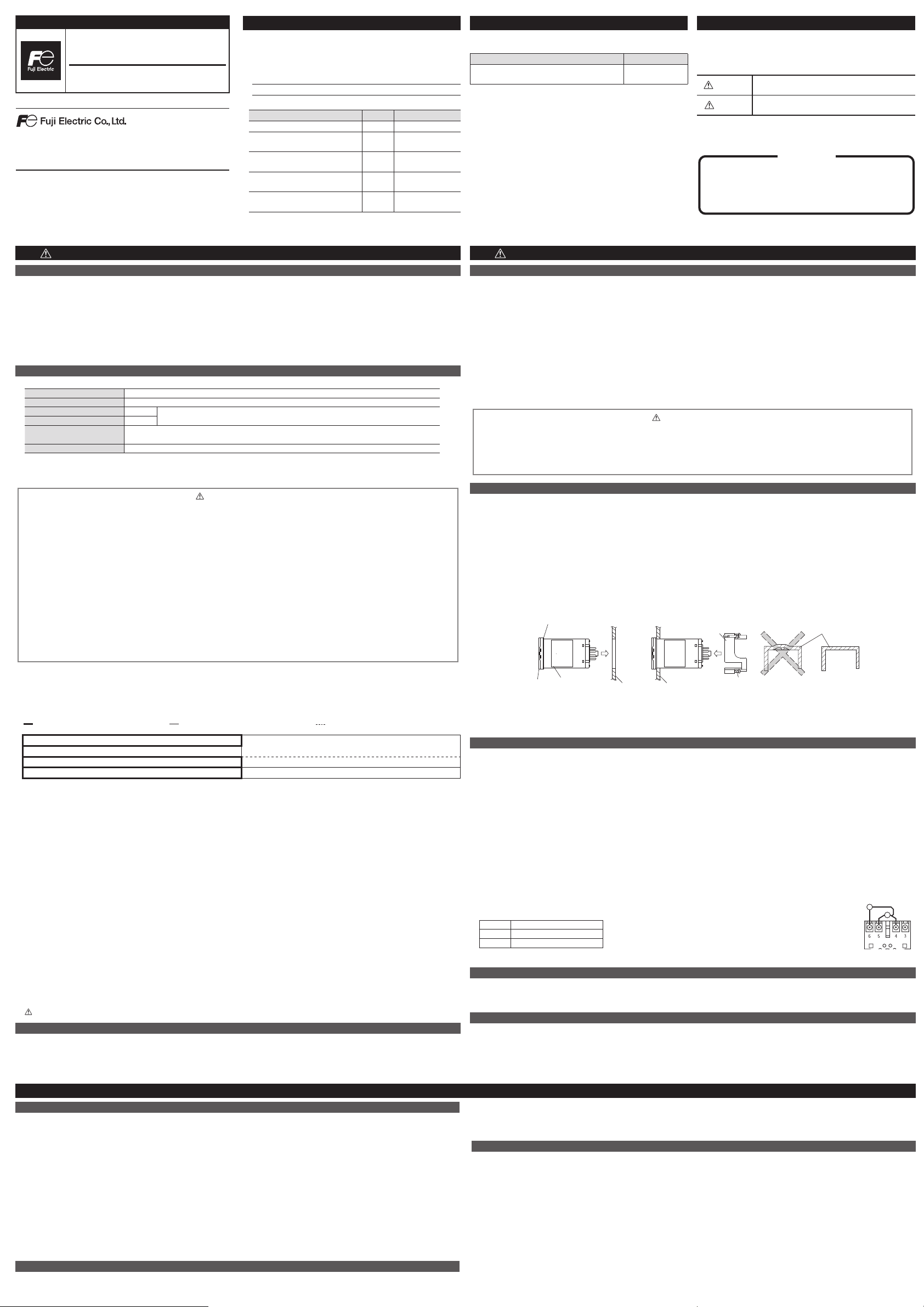
2-2. Cautions when Attaching to the Panels
●
Insert the controller unit into the panel cutout from the front, and then put the mounting bracket from the rear. The mounting
bracket should be pushed in until the controller is securely fixed to the panel. If there is a slight gap remaining, gently tighten the
two screws until the gap disappears. (Make sure not to over tighten the screws, as doing so may result in the mounting bracket
separating from the stopper.)
●
The front of this equipment is waterproof in compliance with NEMA-4X standards (IP66- equivalent). To effect waterproof, the
included packing is shall be attached between the controller and the panel according to the guidelines below. (Incorrect
attachment may cause the equipment to lose its waterproof capabilities.)
(1) As shown in Fig. 1, insert to the panel after attaching the packing to the equipment case.
(2) As shown in Fig. 2, tighten the screws of the mouthing bracket so that no gaps can remain between the equipment face, the
packing and the panels. Once finished, confirm that there are no changes in shape such as displaced or improperly-fitted
packing, etc. as shown in Fig. 3
< Attachment on vertical surface (Horizontal attachment) >
Mounting
bracket
Packing
Case
(Good)
Case
Fig. 3
Case
(Bad)
Fig. 2Fig. 1
PanelPanel
Screw
UnitUnit
Front
Packing
●
Note that NEMA-4X and IP66 are not subject to UL/cUL certificate.
●
If the panel does not have enough strength, gaps may develop between the packing and the panel to lose waterproofing capabilities.
●
In order to aid heat dissipation, do not block the sides of the equipment.
●
Do not block the air vents on the top and bottom of the case.
2-3. Cautions for Wiring
●
For thermocouple input, use the designated compensation lead; for resistance bulb input, use wires with small lead wire
resistance and without any resistance difference among the three wires.
●
To avoid noise conductor effects, input signal wires should be separated from electric power lines or load lines.
●
Input signal wire and output signal wire should be separated each other. And both should be shield wire.
●
If there is a lot of noise from the power source, adding an insulation transducer and using a noise filter is recommended. Always
attach a noise filter to a panel that is grounded securely, and keep the wiring between the noise filter output side and the
measuring equipment power terminal wiring to a minimum length. Please do not attach fuses and switches, etc. to the noise filter
output wiring; otherwise the filter’s effectiveness will be decreased.
●
Twisting the power wires is effective when connecting the wires. (The shorter the pitch of the twist, the more effective the
connection is against noise.)
●
Operation preparation time is required for the contact output when power is turned on. If using it as a signal to an external
interlock circuit, please couple it with a delayed relay.
Concerning the output relay, connecting the maximum rated load will shorten the product’s life; so please attach an auxiliary
relay. If the output operation frequency is high, selecting a SSR drive output type is recommended.
[Proportionate cycles] Relay output: 30 seconds or more, SSR drive output: 1 second or more
●
When inductive loads such as magnetic opening/closing equipment, etc. as relay output equipment are
connected, use of a surge absorber is recommended in order to protect the contacts against opening/closing
surges and to ensure long-term use. Recommended specification for the surge absorber
Voltage Nominal varistor voltage
100 V 240 V
200 V 470 V
Attachment position: between the relay control output contacts.
2-4. Key Operation Cautions/Error Operations
●
The alarm function does not work properly when an error takes place unless the settings are made correctly. Always verify its
setting before operation.
●
If the input wiring breaks, the display will read “UUUU” or “LLLL”. When replacing the sensor, always turn the power OFF.
2-5. Others
●
Please do not wipe the equipment with organic solvents such as alcohol or benzene, etc. If wiping is necessary, use a neutral
cleaning agent.
●
Do not use mobile phones near this equipment (within 50 cm). Otherwise a malfunction may result.
●
Trouble may occur if the equipment is used near a radio, TV, or wireless device.
●
This equipment should be treated as an industrial waste when it is disposed of.
CAUTION
The contents of this manual are subject to change without notice.
This manual is complied with possible care for the purpose of
accuracy, however, Fuji Electric shall not be held liable for any
damages, including indirect damage, caused by typographical
errors, absence of information or use of information in this manual.
3-1. Scope of warranty
If malfunction occurs in the period of warranty due to Fuji Electric, the malfunctioning parts are exchanged or repaired for free. However,
in the case where an engineer needs to visit your place for replacement or repair, you will be charged our call out fee. Please note that
we cannot provide commissioning and/or readjustment for whole system including our product at repair or replacement of failed parts.
The warranty does not apply to the following cases.
(1) The malfunction occurs due to inappropriate conditions, environment, handling or usage that is not instructed in a catalog,
instruction book or user’s manual.
(2) The malfunction is caused by the factors that do not originate in the purchased or delivered product.
(3) The malfunction is caused by other devices or software design that does not originate in Fuji Electric products.
(4) The malfunction occurs due to an alteration or repair that is not performed by Fuji Electric.
(5) The malfunction occurs because the expendable parts listed in an instruction book or connectable were not maintained nor
exchanged in an appropriate manner.
(6) The malfunction occurs due to factors that were not foreseeable by the practical application of science and technology at the
time of purchase or delivery.
(7) The malfunction occurs because the product is used for an unintended purpose.
(8) The malfunction occurs due to a disaster or natural disaster that Fuji Electric is not responsible for.
3-2. Exclusion of liability for loss of opportunity
Regardless of the time period of the occurrence, the amount of compensation assumed by Fuji Electric for damage, excluding
which is caused by intentional acts or acts of gross negligence or illegal act by Fuji Electric, shall not exceed the amount stipulated
in the contract with the customer.
Fuji Electric is not liable for the damage to products that were not manufactured by Fuji Electric, incidental damages or
consequential damages, or damage caused due to special situations regardless of whether it was foreseeable or not, or passive
damages such as opportunity loss or lost profits of the purchaser.
3-3. Scope of application
●
This equipment must be used under the following conditions:
The use of the equipment incurs no risk of a serious accident even if a failure or malfunction occurs on the equipment, and in
case of product failure or malfunction, safety measures such as redundant design, prevention of malfunction, fail safe setting,
foolproof mechanism are provided outside of the equipment by the user.
●
The product described in this document is designed and manufactured as a general-purpose products for general industrial applications.
●
The warranty does not apply to the following cases:
For the use not described in or beyond the conditions or environment specified in the instruction manual or the user manual,
For the use which has large influence on publicity including nuclear power and other power generation, gas, and/or water,
For the use in which safety is especially required, because it may seriously affect railroads, vehicles, combustion equipment,
medical equipment, entertainment devices, safety equipment, defense equipment, and/or human lives and property.
However, we will study the possibility of application of the equipment for the above use, if the user limits the usage of it and agrees
to require no special quality. Please consult us.
3. Limited warranty
Example
Page 2
6-1. Terminal Connection Diagram (Without alarm functions 8-pin socket)
Thermocouple
Universal input
–
+
A
B
B
–
+
+
–
CurrentVoltage
Process value input
(When the 5th code is “A”)
RTD*
1
Universal input
RTD
CurrentVoltage
(When the 5th code is “N”)
–
+
A
B
B
–
+
+
–
Thermocouple
*
1
Control output 1
SSR drive
output
Relay
output
Current
output
–
+
–
+
50/60Hz*250/60Hz*
2
100 to 240VAC
24VDC/AC
Power supply
*1: The terminal layout differs from that of PXW4/PXZ4/PXV4.
6-2. Terminal Connection Diagram (With alarm functions 11-pin socket)
Process value input
–
+
–
+
Control output 1
SSR drive
output
Relay
output
Current
output
Alarm output
Common
Alarm output1
(AL1)
Alarm output2
(AL2)
50/60Hz*250/60Hz*
2
100 to 240VAC
24VDC/AC
Power supply
(When the 5th code is “N”)
Thermocouple
Universal input
RTD
CurrentVoltage
–
+
A
B
B
–
+
+
–
*
1
(When the 5th code is “A”)
Thermocouple
Universal input
–
+
A
B
B
–
+
+
–
RTD*
1
CurrentVoltage
*2: Check the power supply voltage before installation.
6. Wiring
5. Installation and Mounting
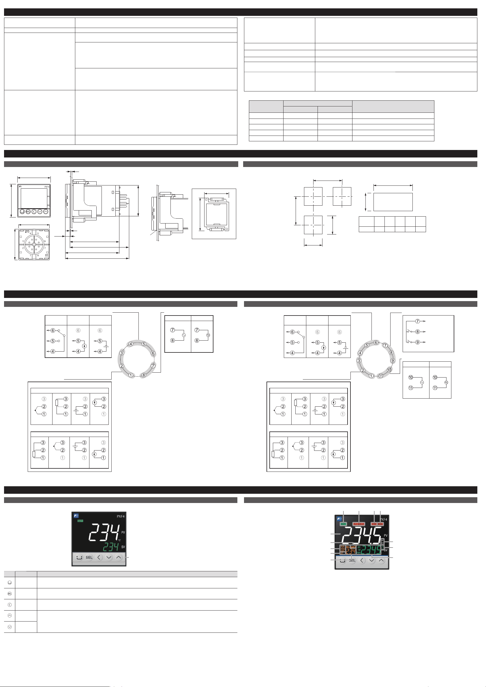
5-1. External Dimensions (unit: mm)
48
48
Panel
Panel thickness 1 to 8
mm*
44.8
44.8
92.4
78.2
85.7
71.5
7.7
1
44.8
57
48
Mounting bracket
Packing
* :KHQXVLQJWKHSDUDPHWHUORDGHUZLWK3;)EHLQJPRXQWHGRQDSDQHOWSDQHOWKLFNQHVVW
5-2. Panel Cut Dimensions (unit: mm)
+0.5
a 0
73 or more
63 or more
45 0
+0.5
Number
of units
23456
93 141 189 237 285a
Side stick mounting (n units)
45 0
+0.5
45 0
+0.5
●
Panel cut dimensions should also meet the above dimensions after the panel is coated.
●
Cautions when Side stick mounting:
In this installing, the waterproof of PXF is lost.
When the power supply is 200 V AC, keep the maximum ambient temperature at 45°C. (We recommend use of a fan, as a heat
radiating measure.)
If any equipment or walls which have a depth of 70 mm exist around this instrument, keep a clearance of at least: 30 mm on the
both sides, 50 mm below, 30 mm above.
7-1. Operation keys
Operation keys
Key Name Allows you to…
USER
●
switch between SV and MV, in the operation mode or during standby.
●
return to the operation mode from the parameter setup mode.
SEL
●
enter the parameter setup mode from the operation mode or standby.
●
finish selecting and save change.
LEFT
●
move the digit when you editing the numerals.
UP
●
change the set value when PXF is in the operation mode or standby.
●
select a parameter in the parameter selection mode.
●
change a parameter setpoint in the parameter editing mode.
DOWN
7. Part names and functions
7-2. Display
(1)
(2) (3) (4) (5)
(6)
(7)
(8)
(9)
(10)
(11)
(12)
(1) Process variable (PV)
●
Indicates the measured value.
●
In the Operation control mode and the Setup mode, the
parameter name is displayed.
●
In the Channel selection mode, the channel number is
displayed.
(2) OUT1 indicator
Lights during control output is ON.
(3) EV1, EV2 indicators
Lights during digital output 1 to 2 are ON.
(4) STBY indicator
Lights during standby.
(5) MANU indicator
Lights during manual mode.
(6) °C/°F indicator
Shows the temperature unit under use.
(7) A, % indicator
Sho
ws the unit being applied to values on SV screen
during the
operation mode.
(8) Set Value (SV)/Manipulated variable (MV)
Indicates the set value or the manipulated variable. The
MV indicator lights during MV display.
(9) Screen No.
Shows screen No. when in parameter setting.
(10) AT indicator
Lights during auto tuning.
(11) RUN/HOLD/END indicators
Lights during ramp/soak operation.
(12) Lock indicator
Lights during key lock.
4. Specifications
Power supply voltage
●
100 (-15%) to 240 (+10%) V AC, 50/60 Hz
●
24 (±10%) V DC/AC, 50/60 Hz
Power consumption 10 VA MAX. (100 to 240 V AC), 5 VA MAX. (24 V DC/AC)
Control output Relay contact output
●
1 SPDT contact, 250 V AC/ 30 V DC, 5 A (resistive load)
SSR drive output (voltage pulse output)*
●
ON voltage: 12 V DC (10.7 to 13.2 V DC)
●
OFF voltage: 0.5 V DC or lower
●
Maximum current: 20 mA DC
●
/RDGUHVLVWDQFHȍ0,1
Current output
●
0 to 20 mA DC/4 to 20 mA DC
●
Accuracy ±5%FS
●
/RDGUHVLVWDQFHȍ0$;
Process value input Accuracy
●
Thermocouple input: 0.5%FS±1digit±1
°C
*except: Thermocouple B: 0 to 400°C: no accuracy assurance
Thermocouple R: 0 to 500°C: 1
%
FS±1digit±1
°C
Other thermocouples: -200 to -100°C: ±2°C ±1 digit
●
RTD: either ±0.8°C ±1 digit or ±0.2% ±1 digit, whichever is larger
●
mV input, voltage input, current input: ±0.3%FS ±1 digitmV
* Note that the sensor should be sufficiently warmed up to secure the accuracy.
Alarm output Relay contact output (AL1 to AL2)
●
1 SPST contact, 250 V AC/30 V DC, 1 A (resistive load)
Loader interface TTL Level
●
Connection method: dedicated cable
●
Communication method: Half-duplex bit serial, asynchronous communication
●
Transmission rate: 38400 bps, no parity
●
Protocol: Modbus RTU compatible
Storage temperature and humidity
-20 to 60°C, 90%RH or less (no condensation)
Operating temperature and humidity
-10 to 50°C, 90%RH or less (no condensation)
Altitude
up to 2000 m
Recommended fuse
250 V AC, 0.1A T(Time-Lag) for 100 to 240 V AC Power supply,
400 V DC/AC, 1 A T(Time-Lag) for 24 V DC/AC Power supply
Service life
Service life: 10 years (at an average temperature of 25°C)
The life is shortened by half when the temperature rises by 10°C (Arrhenius’ law). If you
use the controller inside a cabinet or the like, please note that the ambient temperature
can rise.
* The following table shows the difference of outputs among other micro-controller X series models.
SSR driving output Allowable load resistance for
4 to 20mA DC output
Voltage Maximum current
PXR3 15 V DC 20 mA 100WRȍ
PXR4/5/7/9 24 V DC 20 mA 600 ȍRUOHVV
PXV3 5.5 V DC 20 mA 600 ȍRUOHVV
PXV/W/Z 24 V DC 20 mA 600 ȍRUOHVV
PXF 12 V DC 20 mA ȍRUOHVV
Page 3

8. Basic Operations
To switch between SV, MV and power
Each time you press ,the displayed value
switches in the following order:
Press and
hold
MV Power
SV
To change the setpoint
Press to display the SV.
Press
or
to change the value.
Press
to move to the next digit.
Press
to save the change.
ĺ6HHWKH³3DUDPHWHUOLVW´RQWKHULJKWSDJH
ĺ)RUGHWDLOVRIWKHSDUDPHWHUV
6HHWKH³3DUDPHWHUOLVW´RQWKHULJKWSDJH
< Operation mode >
< Operation control mode >
1
2
3
To change the setpoint
Press
or
to change the parameter.
Press
select the parameter you want to
edit.
ĺThe parameter setpoint starts blinking.
Press
or
to change the setpoint.
Press
to save the change.
1
2
3
4
< Channel selection mode >
To change the channel
1
Press and
hold
Press or .
CH1
Pid
CH2
Plt
CH3
PRG
CH4
MoN
CH5
ALM
CH6
SEt
CH7
SYS
CH8
MAtH
CH11
dSP
CH12
&)*
CH13
PASS
< Setup mode >
To change a parameter setpoint
Press
or
to select the parameter
you want to edit.
Press
.
ĺThe parameter setpoint starts blinking.
Press
or
to change the value.
To change the digit, use
.
Press
.
1
2
3
4
ĺ6HHWKH³3DUDPHWHUOLVW´RQWKHULJKWSDJH
●
Operation mode
In this mode the normal operation is performed. The process value (PV) and the
set value (SV) are displayed. The device starts in this mode when you turn on the
power. You can change the set value (SV) in this mode. You can check the output
value (MV) and the amount of electric ower by switchin the screen.
●
Operation control mode
In this mode you can put the device to standby or change the alarm set value.
●
Channel selection mode
In this mode you can select the parameter channel to be displayed.
●
Setup mode
In this mode you can setup each parameter. This mode includes the parameter
selection submode and the parameter editing submode, which can be switched by
key. In the parameter selection submode, you can switch between parameters
by using
keys. In the parameter editing submode, you can change parameter
values by using
keys.
Changing MV (control output values)
1
Press to switch to the Operation control mode.
2
Press to change the value of the parameter “ ”.
3
Press
to change “ oFF ” to “ oN ”, and then press to save the change.
(MANU indicator appears.)
4
Press to display the MV.
(MANU indicator appears.)
5
Press or to change the MV.
(Changes are reflected to the MV as it is changed.)
11. Error Indications
This controller has a display function to indicate several types of error code shown below. If any of the error code is displayed,
please eliminate the cause of error immediately. After the cause is eliminated, turn off the power once, and then re-start the
controller.
Display Possible cause Control output
“ ”
(1) Thermocouple burnout.
(2) Resistance bulb sensor (A) burnout.
(3) PV exceeds upper limit of the range by 5%FS.
The controller outputs the specified value for an
error.
(The value can be set in parameter Flo1)
“ ”
(1) Resistance bulb sensor B or C wire burnout.
(2) Resistance bulb sensor (between A & B or A &
C) short.
(3) PV is below lower limit of the range by 5%FS.
(4) Burnout or short in the voltage input.
PV < -199.9
Control operation is continued
Note)
Control operation is continued as long as the
accuracy is above -5%FS. When the accuracy
declines to be lower than -5%FS, the controller
outputs the specified value for an error.
“
”
(SV flickers)
Incorrect setting (Pvb/PvF) The controller outputs the specified value for an
error. (The value can be set in parameter Flo1)
PV is not displayed Check the set value of DSPT. Normal control
* The controller does not have to be restarted
SV is not displayed Check the set value of DSPT. Normal control
* The controller does not have to be restarted
Parameters may not
be displayed
Check the settings of Ch11 DSP. Normal control
* The controller does not have to be restarted
“ ”, “ ”
Alarm 1 or alarm 2 is occurred under the condition
that ALMF is set to 1 or 3.
Normal control
“ ”
The number that relay has operated reached the
RYCN (relay contact life limit) under the condition
that ALMF is set to 1 or 3.
“ ”
The number of days that the device has operated
reached the oPtM (upper limit of operating days)
under the condition that ALMF is set to 1 or 3.
12. Model Specifications
Specifications
45678
PXF
2U
-
9 10111213
<Front panel size W × H>
48×48mm
<Input signal>
Universal input
Universal input (PXW/Z/V)
<Control output>
Relay contact (SPDT)
SSR drive output
Current output
<Terminal form>
Socket type
<Revision code>
<Alarm output>
None
2 points
<Power supply voltage>
100 to 240V AC
24 V AC/DC
ʊ
4
U
Y
0
0
2
V
B
4
G
B
C
E
A
N
4
5
6
7
8
9
10
11
12
13
0Y04
Digit
Note
9. Setting the Temperature Controller
9-1. Input Setting
Set the type and the range for input sensor. Input can be set in
the setup menu (“
”
).
For more on input types, input scaling, decimal point location,
and input codes, see “10. Input Range and Codes (standard
range)”.
1
Choose an input type (“ ”)
Check the type of the thermocouple or resistance bulb
which is used.
ź
2
Set the PV scaling (input range) (“ ” / “ ”)
Set Pvb to the lower limit of the temperature range and
PvF to the upper limit.
It is recommended to set the values at the standard range,
even though they can be set at values beyond of it.
There is no standard range for DC voltage or DC current
input. (-1999 to 9999, lower limit<upper limit)
ź
3
Set the decimal point location (“ ”)
Sets whether or not to display digits after the decimal
point. Two digits can also be displayed after the decimal
point when using 1 to 5V DC, and 4 to 20mA DC.
Point
PV scaling and decimal point location can be
used with the factory settings.
9-2. Output Setting
Sets the control output. (Only when the output is current or
voltage.)
1
Sets the range of the control output (OUT1) (“ ”)
Choose any of 0 to 5V, 1 to 5V, 0 to 10V, 2 to 10V, 0 to
20mA or 4 to 20mA DC.
9-3. Control Setting
Sets controls to normal operation or reverse operation.
●
Reverse operation:
As the process value (PV) rises, the control output (MV)
becomes smaller. Used to heat the control object.
●
Normal operation:
As the process value (PV) rises, the control output (MV)
becomes larger. Used to cool the control object.
1
Set the normal or reverse operation (“ ”)
Choose any of the following combinations of heat and cool
to suit your system.
REV Control output 1
RV-- Reverse
No-- Normal
9-4. Alarm Output Setting
Changing the DO type setting, set as below.
●
Set the “do2t” to the value output from AL1.
●
Set the “do3t” to the value output from AL2.
10. Input Range and Codes (standard range)
Input type
Input code
Measurement
range (°C)
Minimum input
increment (°C)
Measurement
range (°F)
Minimum input
increment (°F)
(PVb, PVF)
(PVT) (PVb, PVF)
RTD
JIS (IEC)
JPt 100
JPT1 0.0 to 150.0 0.1 32.0 to 302.0 0.1
JPT2 0.0 to 300.0 0.1 32.0 to 572.0 0.1
JPT3 0.0 to 500.0 0.1 32.0 to 932.0 0.1
JPT4 0.0 to 600.0 0.1 32 to 1112 1
JPT5 -50.0 to 100.0 0.1 -58.0 to 212.0 0.1
JPT6 -100.0 to 200.0 0.1 -148.0 to 392.0 0.1
JPT7 -199.9 to 600.0 0.1 -328 to 1112 1
Pt 100
PT1 0.0 to 150.0 0.1 32.0 to 302.0 0.1
PT2 0.0 to 300.0 0.1 32.0 to 572.0 0.1
PT3 0.0 to 500.0 0.1 32.0 to 932.0 0.1
PT4 0.0 to 600.0 0.1 32 to 1112 1
PT5 -50.0 to 100.0 0.1 -58.0 to 212.0 0.1
PT6 -100.0 to 200.0 0.1 -148.0 to 392.0 0.1
PT7 -199.9 to 600.0 0.1 -328 to 1112 1
PT8 -200 to 850 1 -328 to 1562 1
Thermocouple J
J1 0.0 to 400.0 0.1 32.0 to 752.0 0.1
J2 -20.0 to 400.0 0.1 -4.0 to 752.0 0.1
J3 0.0 to 800.0 0.1 32 to 1472 1
J4 -100 to 1000 1 -148 to 1832 1
K
K1 0 to 400 0.1 32 to 752 0.1
K2 -20.0 to 500.0 0.1 -4.0 to 932.0 0.1
K3 0.0 to 800.0 0.1 32 to 1472 1
K4 -200 to 1300 1 -328 to 2372 1
R R 0 to 1700 1 32 to 3092 1
B B 0 to 1800 1 32 to 3272 1
S S 0 to 1700 1 32 to 3092 1
T
T1 -199.9 to 200.0 0.1 -199.9 to 392.0 0.1
T2 -199.9 to 400.0 0.1 -199.9 to 752.0 0.1
E
E1 0.0 to 800.0 0.1 32 to 1472 1
E2 -150.0 to 800.0 0.1 -238 to 1472 1
E3 -200 to 800 1 -328 to 1472 1
L L -100 to 850 1 -148 to 1562 1
U
U1 -199.9 to 400.0 0.1 -199.9 to 752.0 0.1
U2 -200 to 400 1 -328 to 752 1
N N -200 to 1300 1 -328 to 2372 1
W W 0 to 2300 1 32 to 4172 1
PL-II PL-2 0 to 1300 1 32 to 2372 1
DC voltage
0 to 5 V DC 0-5V
-1999 to 9999
(Range where
scaling is allowed)
—
-1999 to 9999
(Range where
scaling is allowed)
—
1 to 5 V DC 1-5V
0 to 10V DC 0-10
2 to 10V DC 2-10
0 to 100mV DC MV
DC current
0 to 20 mA DC 0-20
4 to 20 mA DC 4-20
Page 4

Parameter List
The following explains each channel parameter.
●
The list also shows the operational range of set values for parameters that are limited.
●
When the PV input lower limit (Pvb), PV input upper limit (PvF), or decimal place position (Pvd) is changed, reconfigure all the initial parameter setting values.
●
When the parameter that has [RESET] on its Remarks column is changed, turn off the power once, and then re-start the controller.
For details, refer to the operation manual (INP-TN5A2400-E) available from our website:
www.fujielectric.com/products/instruments/
Operation control parameter
Parameter
Function
Factory default
setting
Remarks
No Display Name
1
Switchover between auto and manual mode Switchover between auto and manual modes oFF
Note 1
2 Switchover between RUN and standby Switchover the operation mode between RUN and standby oFF
4
Ramp soak control command Changes ramp soak run states oFF Note 2
5
Auto-tuning run command Runs auto-tuning. oFF
6
Alarm output latch release command Cancels the alarm output latch state oFF
7
SV selection Chooses the SV No. used for control LoCL
Note 3
8 PID selection Chooses the PID No. used for control LoCL
9
ALM1 set value Sets the alarm value for ALM1. 2.50%FS10
11
12
ALM2 set value Sets the alarm value for ALM2. 2.50%FS13
14
27
Electric power calculation command
Switches among on/off/hold of electric power calculation.
oFF
28
Key lock Sets the key lock to prevent wrong operation oFF
Note 1: This parameter is not displayed in default setting. If you need to change this parameter, change the setting of “Ch11 dSP” so that it appears.
Note 2: Displays End (when ending) or GS (during guaranty soak).
Note 3:
When changing the SV with the front key, do not change the “Svn” parameter via communication. Otherwise, the changed SV may not be stored correctly.
Note 4:
“SvL” and “Svh” must be set so that SvL < Svh. When you change the values for “SvL” and “Svh”, check SV 1 (“Sv1 Ch2”) through SV 7 (“Sv7 Ch2”).
Note 5: Set the same value as the one for the Normal/Reverse setting (“rEv Ch1”).
Note 6: Do not change this parameter during the ramp soak operation. Be sure to set “PrG” = “oFF” before changing the parameter.
Note 7: Displayed when OUT1 is current or voltage output.
Note 8: Do not change it during calculation.
Note 9: Refer to the Operation Manual for the detail of calculation functions.
CH1 PID (control parameters)
Parameter
Function
Factory default
setting
Remarks
No Display Name
50
Proportional band (%) Sets the proportional band of the PID parameter. 5.0%
51
Integration time
Sets the integration time of the PID parameter.
Setting "0" will turn off integration.
240 (sec)
52
Differential time
Sets the differential band of the PID parameter.
Setting "0" will turn off differentiation.
60.0 (sec)
53
ON/OFF control hysteresis Sets the hysteresis width for the ON/OFF control. 0.25%FS
54
Cooling proportional band coefficient
Sets the proportional band coefficient for cooling.
Setting "0.0" will turn the cooling into an ON/OFF control.
1.0
55
Dead band (%)
Shifts the cooling proportional band from the set value
0.0%
56
Output convergence value (%) Offset value which is added to the MV output value 0
57
Anti-reset windup Sets the range of integration control 100%FS
58
Normal/reverse operations Sets the control action (normal or reverse). RV-- [RESET]
59
SV limit (lower) Sets the lower limit of SV 0.00%FS Note 4
60
SV limit (upper) Sets the upper limit of SV 100.00%FS Note 4
61
OUT1 proportion cycle
Sets the proportion cycle of the control output (OUT1) (contacts, SSR
drive)
30 (relay)
2 (SSR)
1 (current)
63
OUT1 lower limit Sets the lower limit of the control output (OUT1) -5.0%
64
OUT1 upper limit Sets the upper limit of the control output (OUT1) 105.0%
67
Type of output limiter Sets the type of output limiter 0
73
Alpha 6HWVGHJUHHVRIIUHHGRPFRHIILFLHQWĮ 40.0%
74
Beta 6HWVGHJUHHVRIIUHHGRPFRHIILFLHQWȕ 100.0%
CH2 PLT (PID palette parameters)
Parameter
Function
Factory default
setting
Remarks
No Display Name
100
SV1 Sets the SV (set value) 0%FS Note 4
101
Proportional band 1 (%) Sets the proportional band. 5.0%
102
Integration time 1 Sets the integration time. 240 (sec)
103
Differential time 1 Sets the differential time. 60.0 (sec)
104
ON/OFF control hysteresis 1 Sets the hysteresis when using the ON/OFF control. 0.25%FS
105
Cooling proportional band 1 (%)
Sets the cooling proportional band. 1.0
106
Dead band 1 (%) Sets the dead band 0.0%
107
Output convergence value 1 (%) Offset value which is added to the control output 0
108
Anti-reset windup 1 Sets the anti-reset windup 100%FS
109
Normal/reverse 1 Sets the control action (normal or reverse). RV--
[RESET]
Note 5
160
SV 7 Sets the SV (set value) 0%FS Note 4
161
Proportional band 7 (%) Sets the proportional band. 5.0%
162
Integration time 7 Sets the integration time. 240 (sec)
163
Differential time 7 Sets the differential time. 60.0 (sec)
164
ON/OFF control hysteresis 7 Sets the hysteresis when using the ON/OFF control. 0.25%FS
165
Cooling proportional band 7 (%) Sets the cooling proportional band. 1.0
166
Dead band 7 (%) Sets the dead band 0.0%
167
Output convergence value 7 (%) Offset value which is added to the control output 0
168
Anti-reset windup 7 Sets the anti-reset windup 100%FS
169
Normal/reverse 7 Sets the control action (normal or reverse). RV--
[RESET]
Note 5
170
PID switching point 1 Sets the PID switching point for palette 1. 0%FS
176
PID switching point 7 Sets the PID switching point for palette 7. 0%FS
177
Max SV selection number Choosing SV with the user key sets it to the maximum possible number. Sv7
178
Max PID selection number Choosing PID with the user key sets it to the maximum possible number. Pid7
CH 3 PRG (ramp soak parameters)
Parameter
Function
Factory default
setting
Remarks
No Display Name
200
Ramp soak operation pattern (Step No.) Sets which steps to use in the ramp soak operation pattern
14
(uses steps 1 to
64)
Note 6
201
Ramp soak time units Sets the units of the ramp soak time hh.MM
202
Ramp soak 1 seg/SV 1 Sets the SV 0%FS
203
Ramp soak 1 seg ramp time Sets the ramp time. 00:00
204
Ramp soak 1 seg soak time Sets the soak time. 00:00
205
Ramp soak 2 seg/SV 2 Sets the SV 0%FS
206
Ramp soak 2 seg ramp time Sets the ramp time. 00:00
389
Ramp soak 63 seg ramp time Ramp soak 63 seg ramp time 00:00
390
Ramp soak 63 seg soak time Ramp soak 63 seg soak time 00:00
391
Ramp soak 64 seg/SV 64 Ramp soak 64 seg/SV 64 0%FS
392
Ramp soak 64 seg ramp time Ramp soak 64 seg ramp time 00:00
393
Ramp soak 64 seg soak time Ramp soak 64 seg soak time 00:00
394
Ramp soak mode Ramp soak mode 0
395
Guaranty soak ON/OFF Guaranty soak ON/OFF oFF
396
Guaranty soak band (Lower) Guaranty soak band (Lower) 1.25%FS
397
Guaranty soak band (Upper) Guaranty soak band (Upper) 1.25%FS
398
PV start PV start oFF
399
Restore mode Restore mode rES
400
Max pattern selection Max pattern selection 14
401
Min pattern selection Min pattern selection 0
CH 4 MON (monitor parameters)
Parameter
Function
Factory default
setting
Remarks
No Display Name
420
Ramp soak progress Displays the progress of the ramp soak —
421
MV1(%)
Displays the output value of the control output (OUT1)
—
424
Remote SV Shows a remote SV. —
425
Heater current (A)
Shows a heater current value.
(A current value when OUT1 is ON.)
—
427
SSR leak current (A)
Shows a leak current value.
(A current value when OUT1 is OFF.)
—
429
Remaining time on timer 1 Displays the remaining time on timer 1 —
430
Remaining time on timer 2 Displays the remaining time on timer 2 —
436
Current (A) Shows a value measured by CT. —
438
Electric power Shows a calculated value for electric power. —
439
Power Displays the calculated amount of electric power. —
440
Number of opetating times (control relay 1) Displayes the number of times that control relay 1 has operated. —
442
Operating days
Displays the number of days oparated, converted from total operating time.
—
443
Error source Displays the source of an error —
446
Current palette No. Displays the PID palette No. currently selected. —
447
Current pattern No. Displays the pattern No. of the ramp soak currently selected. —
CH5 ALM (monitor parameters)
Parameter
Function
Factory default
setting
Remarks
No Display Name
470
ALM1 alarm type Set the alarm type for ALM1. 0
471
ALM1 hysteresis Sets the hysteresis for alarm output 1 ON/OFF 0.25%FS
472
ALM1 delay Sets the delay before detecting alarm output 1 0
473
ALM1 delay time units Sets the delay time units for alarm output 1 sec
474
ALM1 option
Assigns the optional functions to ALM1
●
Ones digit: alarm output latch
●
Tens digit: error alarm
●
Hundreds digit: inverted output
●
Thousands digit: hold reset
0000
475
ALM2 alarm type Set the alarm type for ALM2. 0
476
ALM2 hysteresis Sets the hysteresis for alarm output 2 ON/OFF 0.25%FS
477
ALM2 delay Sets the delay before detecting alarm output 2 0
478
ALM2 delay time units Sets the delay time units for alarm output 2 sec
479
ALM2 option
Assigns the optional functions to ALM2
●
Ones digit: alarm latch bit mask
●
Tens digit: error alarm bit mask
●
Hundreds digit: inverted output bit mask
●
Thousands digit: hold reset bit mask
0000
511
Electricity alarm Sets the value for electricity alarm. 0
CH 6 SET (setup parameters)
Parameter
Function
Factory default
setting
Remarks
No Display Name
530
PV input type Sets the type of input sensor K1 [RESET]
531
PV input lower limit Sets the lower limit of PV input 0 [RESET]
532
PV input upper limit Sets the upper limit of PV input 400 [RESET]
533
Decimal point position Sets the decimal point position for the PV/SV 0 [RESET]
535
Square-root extractor cut point Sets the cut point for square root calculation. -0.1%
536
PV input shift Sets the amount of shift for PV input 0.00%FS
538
PV input filter Sets the time constant for the PV input filter 5.0 sec
547
OUT1 range Sets the range of the control output 1(OUT1) 4-20 Note 7
549
MV1 during FALT Sets the output value for the control output (MV1) during FALT -5.0%
551
MV1 during Soft Start
Sets the value for the control output (MV1) during soft start
105.0%
553
Soft Start set time Sets the time from startup to the finish of soft start 00:00
554
MV1 during standby
Sets the value for the control output (MV1) during standby
-5.0%
556
Standby mode Sets on/off of the alarm output during standby 0 [ RESET]
561
Fixed voltage value Sets the voltage for calculating electric power 100 (100 V)
562
Current value for simple power calculation Sets the current value for simple power calculation 0 (0.0A)
564
Decial point position for electric power Sets the position of decimal point for calculationed power consumption. 1 : 0.1 Note 8
565
Power factor for simple calculation Sets the power factor for simple calculation 1.00
566
Upper limit of relay contact operation
Sets the upper limit on the number of times a relay contact can operate.
If you set it to 0, no alarm will be generated.
100
(100,000 times)
567
Upper limit of operating days
Sets the upper limit on the number of days the device operates. If you
set it to 0, no alarm will be generated.
3650
(3650 days)
Ch 7 SYS (system parameters)
Parameter
Function
Factory default
setting
Remarks
No Display Name
590
USER key Assigns the function to the [USER] key 0
591
USER + UP key $VVLJQVWKHIXQFWLRQWRWKH>86(5@NH\ 1
592
USER + DOWN key Assigns the function to the [USER]+ V key 5
599
OUT1 output type Selects the content to be output from OUT1 1
602
DO1 output type Sets the trigger for DO1 3
603
DO2 output type Sets the trigger for DO2 4
607
LED indicator assignment (OUT1)
Selects the content for OUT1 to indicate. 1
609
LED indicator assignment (Ev1)
Selects the content for EV1 lamp to indicate. 110
610
LED indicator assignment (Ev2)
Selects the content for EV2 lamp to indicate. 111
615
LED indicator assignment (STBY)
Selects the content for STBY lamp to indicate. 12
616
LED indicator assignment (MANU)
Selects the content for MAN lamp to indicate. 13
617
Ramp SV ON/OFF Sets the ramp SV ON/OFF oN
618
Ramp SV-Decline
Sets the slope for a falling SV during ramp SV operations
0.00%FS
619
Ramp SV-Incline
Sets the slope for a rising SV during ramp SV operations
0.00%FS
620
Ramp SV-slope time unit Sets the unit of time for the slope during ramp SV operations hoUr
621
Ramp SV - display mode
Displays the SV during ramp operations or the SV goal value on the SV
display
rMP
622
Control method Selects the control method. Pid
626
Start mode Sets the operation mode during startup AUTO
627
Control operation cycle Sets the control operation cycle. 0.1S
628
PID pallette switching method Sets the method for switching among PID pallette. 0
Ch 12 CFG (configuration parameters)
Parameter
Function
Factory default
setting
Remarks
No Display Name
940
Operation timeout (return to PV/SV display)
Sets the time until the display returns to PV/SV screen from setting screen.
60S
942
Blinking SV during Soft Start Sets whether or not to blink SV during Soft Start. ON
943
Blinking PV/SV at ALM Sets whether or not to blink PV/SV when alarm becomes ON. 0
944
Display timeout Sets the time until the display automatically turns off. oFF
945
PV/SV Display off Sets ON/OFF of PV and SV display 0
946
Blinking PV at input error Sets whether or not to blink PV at an input error 0
947
Brightness Sets the brightness of LED backlight 3 3 is the brightest
948
Control at burnout
Sets whether to continue or to stop control when the device detects a
burnout of PV input
oFF
950
Model code Shows model code
P
951
X
952
F
962
963
Reset
Resets the controller
oFF
965
Software version
Shows the software version
—
966
967
968
Ch 13 PASS (password parameters)
Parameter
Function
Factory default
setting
Remarks
No Display Name
990
Password1 setup Sets password 1. 0000
991
Password2 setup Sets password 2. 0000
992
Password3 setup Sets password 3. 0000
Ch 8 MATH (calculation parameters)
Parameter
Function
Factory default
setting
Remarks
No Display Name
650
Simple calculation ON/OFF Sets ON/OFF of simple calculation oFF Note 9
Ch 11 DSP (parameter mask)
Parameter
Function
Factory default
setting
Remarks
No Display Name
1 — Parameter mask Sets the parameters to be displayed/not displayed. — Values differ depending on the model.
 Loading...