

Page 1
Fuji Instrumentation & Control
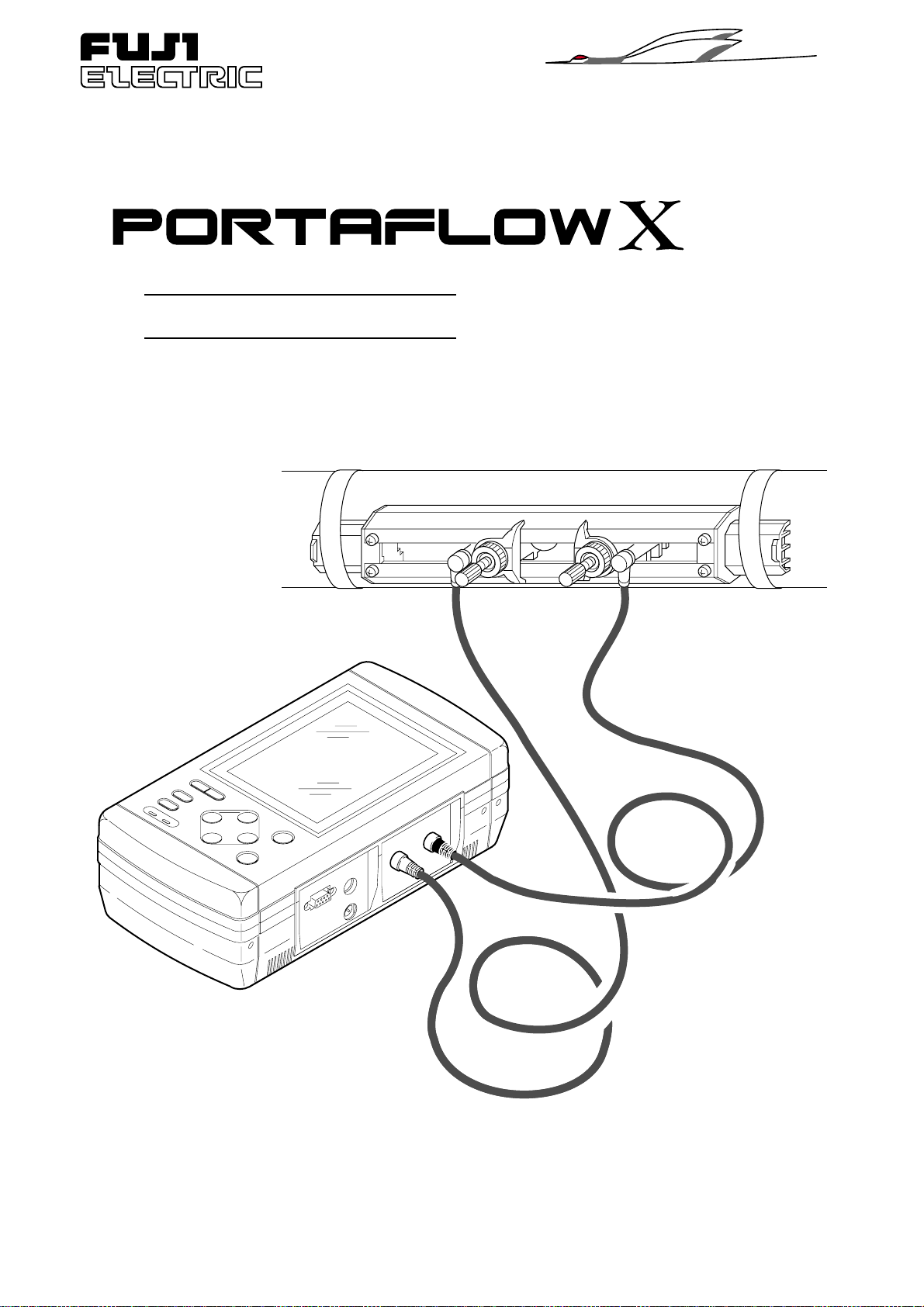
Portable Ultrasonic Flowmeter
Quick Reference
ECNO:622HP
Page 2

Page 3

CONTENTS
CONTENTS
1. STANDARD SELECTION OF DETECTOR ....................................
2. CONDITIONS OF DETECTOR MOUNTING POSITIONS..............
3. MEASURABLE FLUID ....................................................................
4. PIPING CONDITIONS ....................................................................
5. MOUNTING METHOD OF DETECTOR ON PIPING......................
6. OPERATION ...................................................................................
6.1 Power ON - How to Select the Language.............................................................................11
6.2 Preparation Prior to Measurement (Zero Adjustment, etc.)...................................................12
6.3 Piping Specification Input Method through Determination of Size for Sensor Spacing .........14
6.4 Error Status Display and Corrective Actions .........................................................................16
6.5 Measurement of Fluid with Unknown Sonic Speed ...............................................................18
7. Q & A.............................................................................................
7.1 How is piping setting made when piping specifications are unknown ? ................................20
7.2 What is the effect of coating outside the piping ? ..................................................................20
7.3 What is the effect of scales in the piping ? ............................................................................20
7.4 What is homogenious fluid through which ultrasonic waves are transmitted ? .....................20
7.5 Is it possible to measure the flow in piping that is not full ?...................................................21
7.6 What happens when the liquid contains air bubbles ? ..........................................................21
7.7 What about mounting the sensor on horizontal piping ? .......................................................22
7.8 What about mounting the sensor on vertical piping ?............................................................22
7.9 When the length of straight piping is short and a pump, valve, orifice, etc. is present,
what is required for measurement ? ......................................................................................22
7.10 How far can the sensor extension cord be extended ? .........................................................22
7.11 What is the approximate accuracy of measurement ? ..........................................................23
7.12 What about error factors ?.....................................................................................................23
7.13 What about comparison with other flowmeters ?...................................................................25
7.14 What is the difference between a Doppler type flowmeter and PORTAFLOW X ? ...............26
7.15 Life span of LCD....................................................................................................................26
20
2
3
5
6
7
8
8. DATA.............................................................................................
(1) Sonic Speed of Solid (at 25°C)..............................................................................................27
(2) Sonic Speed of Water............................................................................................................27
(3) Sonic Speed of Fluid .............................................................................................................28
Note) This manual provides information about the converter type 2.
ECNO: 622
27
1
Page 4
1. STANDARD SELECTION OF DETECTOR
rotceteDepyT)mm(retemaidedisnI(°CegnarerutarepmeT)
rosnesretemaidllamS22DLF001ot31001ot04–
–
–
–
–
001ot04
08ot04
08ot04
002ot04
rosnes
)dradnats(llamS21DLF004ot05
rosnesegraL15DLF0006ot002
0021ot002
rosneserutarepmet-hgiH23DLF004ot05
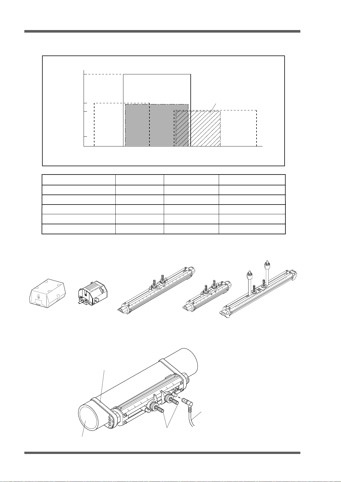
(1) Selection from 5 types according to applications
Fluid temperature (°C)
200
High-temperature
sensor
100
80
Small
diameter
sensor
0
–40
13 50 100 200 400
Middle sensor
(2) Shape of each sensor
FLD41
Small
sensor
(standard)
Pipe size (mm)
Middle sensor
1200
Large
sensor
6000
Large type (2pcs)
(Type: FLD51)
Middle type (2pcs)
(Type: FLD41)
Small type (standard)
(Type: FLD12)
(3) Example of sensors mounted on pipe
Cloth belt
2
Piping
Element holder
Small diameter
(Type: FLD22)
Exclusive cable
High-temperature
(Type: FLD32)
ECNO: 622
Page 5
2. CONDITIONS OF DETECTOR MOUNTING POSITIONS
• The piping must be filled with fluid which is free from air bubbles and foreign objects.
• Straight piping greater than 10D must exist on the upstream side and greater than 5D
on the downstream side.
• Elements (pump, valve, etc) on the upstream side must be greater than 30D away to
prevent disturbances.
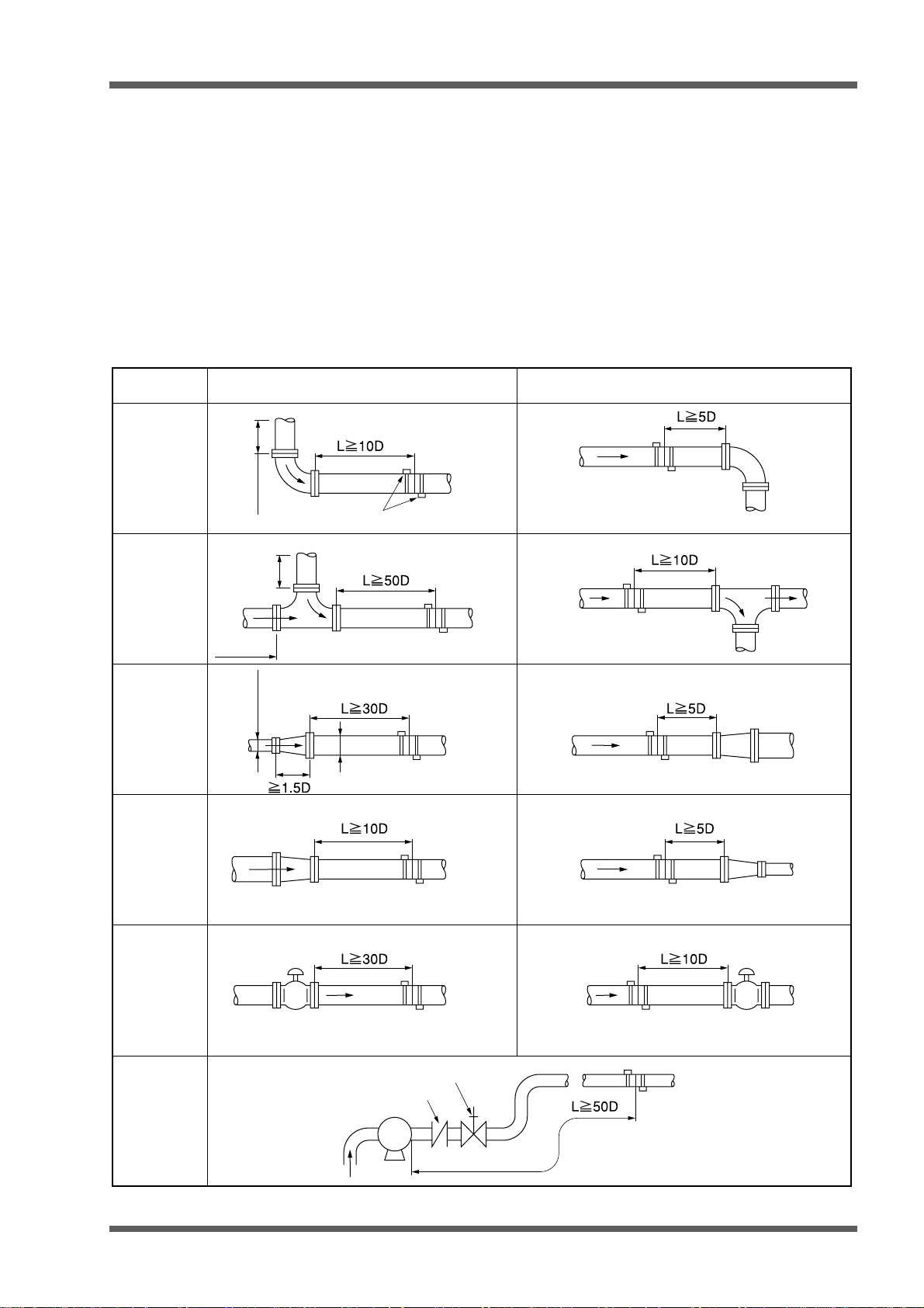
(1) Necessary straight pipe length
Classification For upstream side For downstream side
90° bend
Tee
Diffuser
Reducer
More than 10D
More than
More than
10D
0.5D
More than
Detector
10D
D
Valves
Pump
ECNO: 622
Flow control valve exists on upstream side.
Stop valve
Check valve
P
Flow control valve exists on downstream side.
3
Page 6
2. CONDITIONS OF DETECTOR MOUNTING POSITIONS
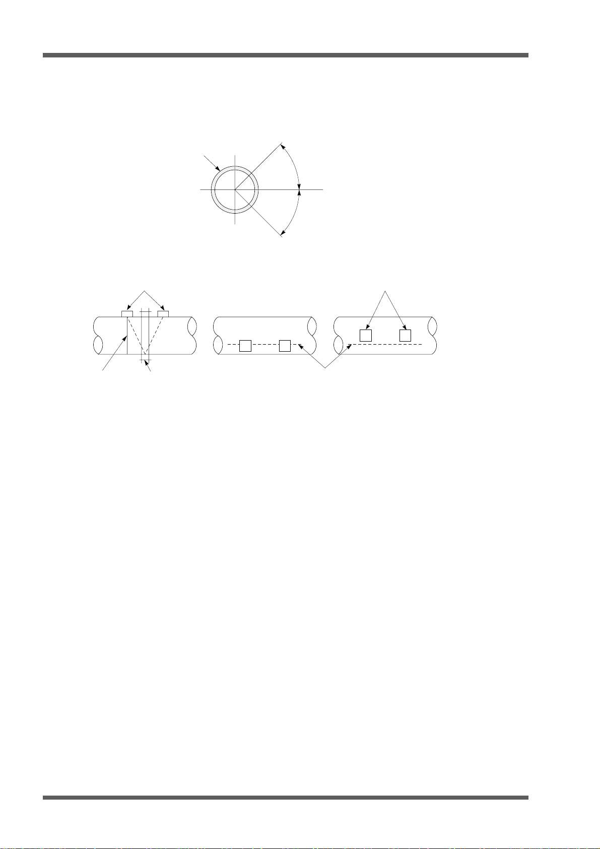
(2) Detector mounting considerations
1) For horizontal piping, the detector should be mounted within ±45° from the water level.
For vertical piping, the detector can be mounted in any external position.
Piping
°
45
Horizon
°
45
2) Avoid mounting the detector at positions with piping distortion, flange or welds.
Welds
Detector
Flange or welds
Welds
Detector
No good No good Good
4
ECNO: 622
Page 7
3. MEASURABLE FLUID
Item
Measurable fluid
Fluid
turbidity
Ultrasonic propagative homogeneous fluids (water, seawater, oil or fluid even
with unknown sonic speed), including the following liquids.
Acetone
Aniline
Ether
Ethylene glycol
Chloroform
Glycerin
Acetic acid
Methyl acetate
Ethyl acetate
Heavy water
Carbon tetrachloride
Mercury
Nitrobenzene
Carbon bisulfide
n. pentane
n. hexane
Spindle oil
Gasoline
10000 (mg/L) or less
Flow condition
Full-filled,axisymmetric and well developed flow
Fluid temperature
per detector
Velocity range
–
32 to 0 to +32m/s
Specifications
rotceteDepyT)mm(retemaidedisnI(°CegnarerutarepmeT)
rosnesretemaidllamS22DLF001ot31001ot04–
–
–
–
–
001ot04
08ot04
08ot04
002ot04
rosnes
)dradnats(llamS21DLF004ot05
rosnesegraL15DLF0006ot002
0021ot002
rosneserutarepmet-hgiH23DLF004ot05
FLD41
Middle sensor
ECNO: 622
5
Page 8

4. PIPING CONDITIONS
Item
Piping diameter
Piping materials
Lining materials
(coating materials
for piping interior)
Specifications
Small diameter sensor
Small sensor (standard)
Middle sensor
Large sensor
High-temperature sensor
Iron
Copper
Ductile cast iron
Cast iron
Stainless steel
Steel
Lead
Aluminum
None
Tar epoxide
Mortar
Rubber
Teflon
Pilex glass or materials with known sonic speed
φ13 to φ100mm
:
φ50 to φ400mm
:
φ200 to φ1200mm
:
φ200 to φ6000mm
:
φ50 to φ400mm
:
Brass
Polyvinyl chloride
Acrylic resin
Mortar
Tar epoxide
Polyethylene
Teflon
FRP
6
ECNO: 622
Page 9
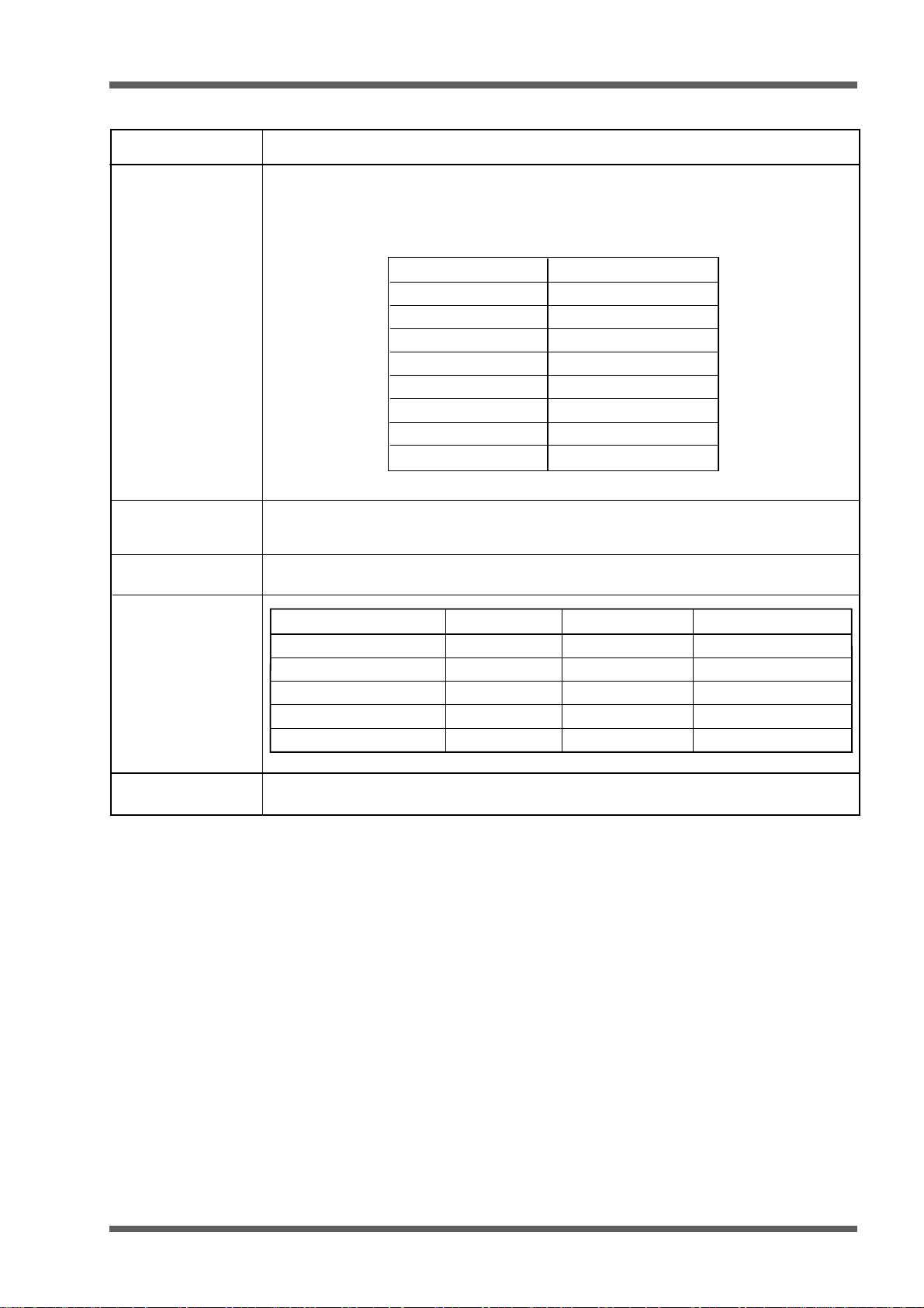
5. MOUNTING METHOD OF DETECTOR ON PIPING
Enter the piping specifications in the parameter of the converter to determine the sensor mounting
dimension and then mount the sensor on the piping.
Loosen the lock nut and slide the sensor so as to
(1)
meet the specified mounting dimension (by
rounding off the displayed mounting dimension
value of the converter below the decimal point),
and then tighten the nut.
Apply the attached silicone grease to the
(2)
transmitting surface of the sensor. Spread the
compound over the entire area.
Element holder
BNC connector
Scale
Lock nut
Cursor
Frame
Saddle
Mounting dimension
(L)
Element holder
Cloth belt
Transmitting
surface
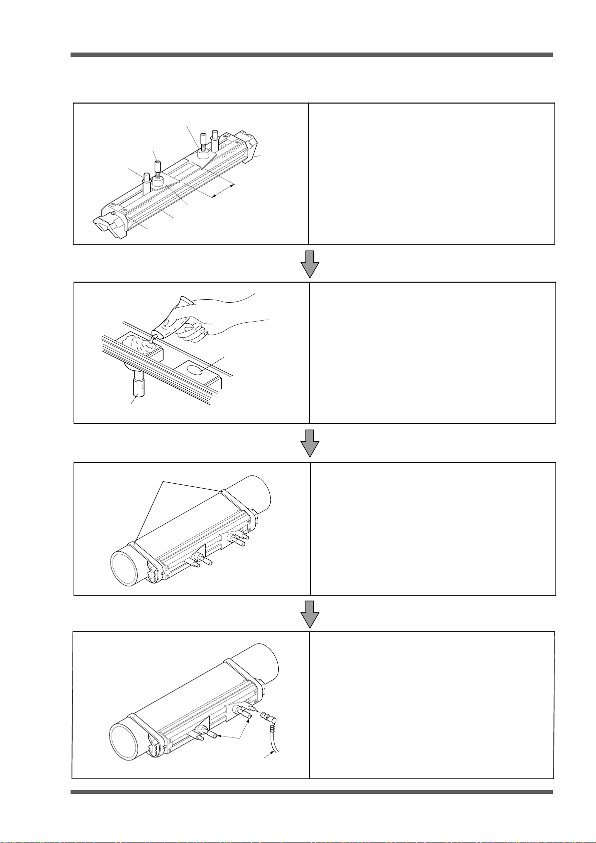
Keep the sensor retracted by turning the element
holder counterclockwise.
After cleaning the surface of the pipe, the sensor
should be mounted.
Fix both ends (saddles) of the sensor to the pipe
(3)
by the attached cloth belts. Mounting will be
facilitated by winding the cloth belts on the pipe in
advance.
Cloth belts are usable at 80°C or lower.
If above 80°C, stainless steel belts should be
used.
ECNO: 622
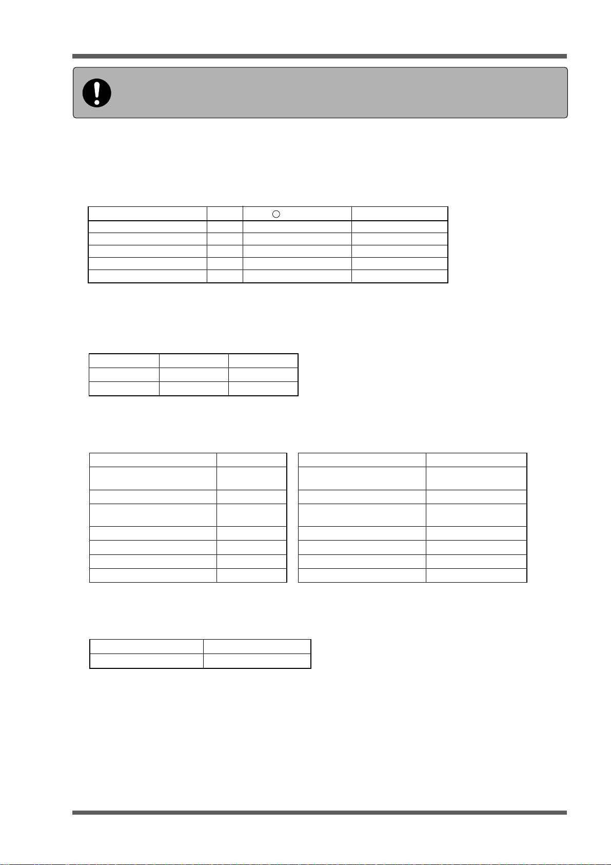
Element holder
Exclusive cable
(4)
Make sure the sensor is mounted in parallel with
the pipe axis and the mounting dimension is
correct. Then, turn the element holder clockwise
until the sensor comes in close contact with
the pipe.
Stop turning the element holder when it tightens
as the transmitting surface comes in contact with
the pipe surface. Be careful not to tighten the
holder excessively.
7
Page 10

6. OPERATION
Be sure to read the following items and record (check) the next page before
using the flowmeter. Read these data together with the instruction manual.
(1) Make sure that the inside diameter of the piping being measured comforms to the
sensor type.
Middle sensor
rotceteDepyT)mm(retemaidedisnI(°CegnarerutarepmeT)
rosnesretemaidllamS22DLF001ot31001ot04
rosnes
rosnesegraL15DLF0006ot002
)dradnats(llamS21DLF004ot05
FLD41
rosneserutarepmet-hgiH23DLF004ot05
0021ot002
–
–
–
–
–
001ot04
08ot04
08ot04
002ot04
(2) Check the lengths of the straight pipe upstream and downstream of the sensor mount-
ing position.
•
Straight piping greater than 10D must exist on the upstream side and greater than 5D on the
downstream side.
•
Elements (pump, valve, etc) on the upstream side must be greater than 30D away to prevent
disturbances.
(3) Check if the piping setting (outside diameter , material, thic kness , etc.) is correct.
•
If the sensor mounting size is not calculated correctly, errors will occur such as window scan
(reception range-over) or no received signal.
(4) Check if the sensor is mounted correctly.
•
If the transmission side of the sensor is not coated sufficiently with silicone grease, receiving
signals will become unstable or errors will occur such as window scans (receiving range-over),
no received signals, etc.
•
If the upstream and downstream side connectors are reversed, a negative flow rate will be
indicated.
(5) Make sure that the zero point adjustment is completed.
•
Fill the piping with measuring fluid, then stop the flow of the fluid to perform a manual zero
adjustment.
(6) Check to see if more than 2 indicators on the upper right of the measurement screen
are working to indicate wave reception.
•
If no indicator is displayed, or if only one is displayed, increase the level of the transmission
voltage.
(7) Check if the analog output range is set correctly.
•
Even when the analog output is not used, an error of analog scale-over will occur unless the
analog output range has been set properly.
* Preparations for measurement have been completed.
Set the integrator, logger, printer, etc., as necessary. Check whether the flow rate is indicated
correctly. If an error message is indicated, display the system check screen and press the
ENT key while setting the cursor on the error checker.
At this time, the error data, the cause of the error and procedures to correct the error are
indicated. Operate the flowmeter according to the instructions.
8
ECNO: 622
Page 11
6. OPERATION
Be sure to record (check) the following items before using the flowmeter.
Date of recording [ day month year] Place of measurement ______________________
Recorded by ___________________________ ________________________________________
(1) Check the inside diameter of the piping to insure it conforms to the sensor type.
Detector Type (Mark on sensor in use) Piping inside diameter
Small diameter sensor FLD22
Small sensor (standard) FLD12
Middle sensor FLD41
Large sensor FLD51
High-temperature sensor FLD32
(2) Check for sufficient lengths of straight pipe upstream and downstream of the sensor
mounting position.
mm
mm
mm
mm
mm
gnipipthgiartS.cte,evlav,pmuP
edismaertspUDtuohtiW/htiW
edismaertsnwoDDtuohtiW/htiW
(3) Check for correct piping settings (outer diameter size, material, thickness, etc.).
.1emanetiSdiulffodniK.7)(/retaw-aeS/retaW
ezisretemaidretuognipiP.2mm
lairetamgnipiP.3 deepsdnuosdiulF/rehtO*s/m
)gnittesdeepsicnos(rehtO*s/m
)mm(ssenkcihtgnipiP.4mmdohtemgnitnuomrosneS.8dohtemZ/dohtemV
lairetamgniniL.5 rosnesfoepyT.9
)gnittesdeepsicnos(rehtO*s/megatlovnoissimsnarT.01
ssenkcihtgniniL.6mmezisgnitnuoM.11mm
fotneiciffeoC/retaw-aeS*
ytisocsivcitamenik
fotneiciffeoC/rehtO*
ytisocsivcitamenik
×1 / ×2 / ×4 / ×8
m
m
(4) Check for correct sensor mounting.
Silicone grease coating No / Yes
No / YesConnector connection check
2
s/
2
s/
(5) Check the zero point adjustment.
Zero point adjustment method: Manual zero clear (stop the flow of fluid for manual zero operation.)
ECNO: 622
9
Page 12

6. OPERATION
(6) Check that more than 2 indicators on the upper right of the measurement screen are
working to indicate received waves.
Number of working indicators: [ ] (If neither indicator or only one indicator is working, increase
the transmission voltage.)
(7) Check if the analog output range is set properly.
Output range set value: M .MMMEM
* Recording (check) has been finished. Set the integrator, logger, printer, etc., as necessary.
Check if the flow rate is indicated correctly. If an error message is indicated, display the system check screen and press the ENT key while setting the cursor on the error check.
At this time, the error data, the cause of the error and corrective action are indicated. Follow
the operating instructions displayed on the screen.
10
ECNO: 622
Page 13

6. OPERATION
6.1 Power ON - How to Select the Language
At the time of purchase of the flowmeter, English is used as the display language. To change it into
Japanese, German or French, use the following procedure.
Once a language is set, it is stored in memory and it is not necessary to reset every time the power
OFF.
Power switch
PORT AFLOW
ON OFF
English
*
ESC
Default display is in English.
To choose a different language,
ESC key while “English”
press
is Flashing for 10 seconds.
If key is not pressed
ESC
within 10 seconds, the main
display in English will
appear.
Select language
Wahle Sprache
Choix de la langue
ENT
FLOW RATE
UNIT:1/s
0.000 0
MEASURE
VELOCITY
UNIT:m/s
0.000 0
+TOTAL
UNIT:ml
0000000
-TOTAL
UNIT:ml
0000000
NO RECEIVED SIGNAL
ENT
The selected language will
appear at start up the next
time.
RESET
RESET
ECNO: 622
11
Page 14

6. OPERATION
6.2 Preparation Prior to Measurement (Zero Adjustment, etc.)
rotceteDepyT)mm(retemaidedisnI(°CegnarerutarepmeT)
rosnesretemaidllamS22DLF001ot31001ot04
rosnes
Middle sensor
*
Straight piping greater than 10D must exist on the upstream side and greater than
5D on the downstream side.
*
Elements (pump, valve, etc) on the upstream side must be greater than 30D away
to prevent disturbances.
)dradnats(llamS21DLF004ot05
rosnesegraL15DLF0006ot002
FLD41
rosneserutarepmet-hgiH23DLF004ot05
0021ot002
–
001ot04
–
08ot04
–
08ot04
–
002ot04
–
Detector selection standard
Power ON
When the power is ON, the
language select screen is
displayed. Select the
Piping specification input
Sensor mounting
language to be used and
then press the ENT key.
x10 0 = 0
x10 1 =10
Measurement start
Measurement end
/Power OFF
Measurement
x10
2
Example)
1.200
Battery alarm
Measurement
99-05-11 11:49
FLOW RATE UNIT:
VELOCITY UNIT:
MEASURE
+
TOTAL UNIT:
–
TOTAL UNIT:
NORMAL
=100
Status display
x10 2 corresponds to l.2 x 100 = 120m /h.
(Measurement cycle: Once/sec)
M3/h
x10
m/s
x10
ml
STOP
RESET
ml
STOP
RESET
More than 2 indicators for standard
measurement. When one or no indicator
is working, the transmission voltage
should be raised.
×1
×2
×4
×8
Zero Adjustment
3
Indicator (receiving wave strength)
ENT
Site setup
Data logger
System setup
Analog
Printer
System check
Description of key symbols
ENT
: ENTRY key (data registration)
ESC
: ESCAPE key (setting suspension)
: Cursor up-shift (set value feed)
: Cursor down-shift (set value return)
: Cursor left-shift (scale change)
: Cursor right-shift (scale change)
PRINT
: Display screen printout (hard copy)
Important!
(1)
Selection of detector mounting
position
1)
Straight piping greater than 10D must exist
on the upstream side and greater than 5D
on the downstream side.
2)
Elements (pump, valve, etc) on the
upstream side must be greater than 30D
away to prevent disturbances
3) The piping must be filled with fluid free from
air bubbles and foreign objects.
(2)
Selection of mounting method
Small diameter sensor and small type (standard)
sensor should be mounted by the V method.
In the following cases, the Z method should be
used for mounting.
• Insufficient mounting space (about 1/2 of the size of
the V method)
• Piping with mortar lining
• Piping is old and presumed to have a deposit of a thick
layer of scales inside the piping.
L = About D
D
V method
L: Mounting size
L = About D/2
D
Z method
(3)
Treatment of detector mounting side
•
Using thinner and sand-paper, remove the
pitches, rust and uneven surface of the detector
mounting piping over the entire mounting area
of (L) + 200mm wide.
•
When the piping exterior is wrapped with jute,
remove the jute and then perform the above
treatment.
•
Horizontal piping should be mounted within
±45° from the horizon.
•
Vertical piping can be mounted at any external
position.
°
45
°
45
(4)
Method of mounting for small sensor
(standard) and small diameter
sensors
(refer to Page 7 of this manual)
1)Loosen the lock nut. After setting to the
mounting position, tighten the lock nut.
2)Coat the sensor transmission side with a
sufficient amount of silicone grease.
3)Attach both ends (saddle) to the piping
using a cloth belt.
4)Make sure that the sensor is mounted in
parallel with the piping and that the
mounting position is correct. Then, turn the
element holder clockwise until the sensor is
firmly fitted to the piping (clockwise;
element moves down, anti-clockwise;
element moves up).
12
ECNO: 622
Page 15

SITE SETUP
SITE SETUP
ZERO ADJUST
MANUAL ZERO
CALIBRATION
SPAN
100.00%
ZERO ADJUST
MANUAL ZERO
SITE SETUP
SITE SETUP
CALIBRATION
Adjustment with “Site
setting/Transmission
voltage”
Important !
(1)
Insufficient coating of grease on the sensor
(2)
Air stays in the piping.
(3)
When the inside of the piping is rusted or the lining material is
peeled off, the number of indicators will not increase even if the
transmission voltage is raised.
(4)
When transmission voltage is raised unnecessarily, the battery
power will be consumed quickly during battery drive
(no problems with measurement ).
Site setup
6. OPERATION
Stop the flow for
zero adjustment
This is the result of automatic calculation.
It can be changed by piping specification input.
SITE SETUP
SITE MEMORY
PIPE PARAMETER
ZERO ADJUST
RESPONSE SET
SITE SETUP
CALIBRATION
CUT OFF
TOTALIZE
MANUAL ZERO
--- SENSOR SPACING ---
255.1mm
Site setup
ENT
Important !
ZERO ADJUST
Under the flow stop condition,
set the cursor for manual zero
adjustment and press the
ENT key
(compulsory zero adjustment).
MANUAL ZERO
CLEAR
ENT
This is used when the flow cannot be stopped.
Since the exact zero adjustment cannot be obtained
(output is within the range of allowable error), the
manual zero adjustment should be
performed after stopping the flow.
ECNO: 622
SITE SETUP
SITE MEMORY
PIPE PARAMETER
ZERO ADJUST
RESPONSE SET
SITE SETUP
CALIBRATION
CUT OFF
TOTALIZE
--- SENSOR SPACING --
255.1mm
MANUAL ZERO
Important !
ENT
CALIBRATION
ZERO
SPAN
In general, 0.000m/s is used for zero, and
100.00% is used for span.
Note that when this value changes, the output
deviates by the amount of the change.
Example) When the span is set to 0.0%, the
100.00%
instantaneous value 0.0 remains
unchanged.
13
Page 16

6. OPERATION
SITE NAME
PIPE MATERIAL
CARBON STEEL
KIND OF FLUID
WATER
WATER
KINEMATIC VISCOSITY
SOUND VELOCITY
PIPE PARAMETER
6.3 Piping Specification Input Method through Determination
of Size for Sensor Spacing
rotceteDepyT)mm(retemaidedisnI(°CegnarerutarepmeT)
rosnesretemaidllamS22DLF001ot31001ot04
rosnes
Middle sensor
*
Straight piping greater than 10D must exist on the upstream side and greater than
5D on the downstream side.
*
Elements (pump, valve, etc) on the upstream side must be greater than 30D away
to prevent disturbances.
)dradnats(llamS21DLF004ot05
rosnesegraL15DLF0006ot002
FLD41
rosneserutarepmet-hgiH23DLF004ot05
0021ot002
–
001ot04
–
08ot04
–
08ot04
–
002ot04
–
Detector selection standard
Power ON
When the power is ON, the
language select screen is
displayed. Select the
Piping specification input
language to be used and
then press the ENT key.
Sensor mounting
Measurement start
SITE SETUP
Site setup
SITE SETUP
PARAMETER MEMORY
PIPE PARAMETER
ZERO ADJUST
MANUAL ZERO
RESPONSE SET
CALIBRATION
CUT OFF
TOTALIZE
--- SENSOR SPACING ---
0.0mm
ENT
Measurement end
/Power OFF
ENT
Measurement
Site setup
Data logger
System setup
Analog
Printer
System check
Description of key symbols
ENT
: ENTRY key (data registration)
ESC
: ESCAPE key (setup suspension)
: Cursor up-shift (set value feed)
: Cursor down-shift (set value return)
: Cursor left-shift (scale change)
: Cursor right-shift (scale change)
PRINT
: Display screen printout (hard copy)
Site name input
(1)
Measurement is possible
without input.
SITE SETUP
PIPE PARAMETER
SITE NAME
(7)
Kind of fluid
KIND OF FLUID
SEA WATER
WATER
KINEMATIC VISCOSITY
1.004E-6 m /s
*
Designation of coefficient of kinematic
viscosity, Table 2
*
When selecting "OTHER", select sonic
speed and coefficient of kinematic viscosity
from Table 2, and enter them.
WATER
OTHER
(2)
(Setting range:13 to 6100mm)
Note) Input the actually
ENT
OTHER
SOUND VELOCITY
KINEMATIC VISCOSITY
Piping outer diameter
(unit: mm)
PIPE PARAMETER
SITE NAME
OUTER DIAMETER
ENT ENT
0013.0 mm
Digit shift
Numeric
value input
After input
measured external size.
Selection of sensor
(8)
mounting method
PIPE PARAMETER
SENSOR MOUNTING
Z
TABLE 2
In general, the V method is used.
But, the Z method is used in the following
cases.
* Mounting space cannot be obtained.
* High turbidity
* Weak receiving wave
* Deposit of thick scale inside the piping
(3)
Piping material
PIPE MATERIAL
CARBON STEEL
STAINLESS STEEL
CAST IRON
COPPER
PVC
ALUMINUM
ASBESTOS
FRP
OTHER
DUCTILE IRON
"Other": Input of sound
speed value, Table
(Setting range:
1000
to 3700m/s
)
ENT
ENT
1
14
ECNO: 622
Page 17

6. OPERATION
ENT
ENT ENT
Numeric
value input
(Setting range :
0.01 to 100.00mm)
ENT ENT
(Setting range :
0.01 to 100.00mm)
ENT
"Other": Input of sound speed
value, Table 1
(Setting range :
1000 to 3700m/s)
20 0.7905 1190 0.407
20 1.0216 1659 1.762
20 0.7135 1006 0.336
20 1.1131 1666 21.112
20 1.4870 1001 0.383
20 1.2613 1923 1188.500
20 1.0495 1159 1.162
20 0.9280 1181 0.411
20 0.9000 1164 0.499
20 1.1053 1388 1.129
20 1.5942 938 0.608
20 13.5955 1451 0.114
20 1.2070 1473 1.665
20 1.2634 1158 0.290
20 0.6260 1032 0.366
20 0.6540 1083 0.489
32 0.9050 1324 15.700
34 0.8030 1250 0.4~0.5
13.5 1.0000 1460 1.004 (20°C)
3230
3206
3000
2460
3206
2260
2170
3080
2050
2640
2644
2505
2500
2505
1900
1240
Vm/s
Fluid name T
°C ρg/cm
3
Vm/s
ν
(×10-6m2/s)
Site setup
Piping thickness
(Unit: mm)
Lining thickness
(4)
Kind of sensor
(9)
Lining material
(5) (6)
Determination of
mounting size
Transmission voltage
(10 )
(11)
PIPE PARAMETERPIPE PARAMETER
PIPE NO.1
SITE NAME
Error of 1mm deviation at φ50: About 1%.
Error of 1mm deviation at φ500: About 0.1%
ENT
ENT
ENT
FLD51
CALIBRATION
CUT OFF
TOTALIZE
--- SENSOR SPACING ------ SENSOR SPACING ---
255.1mm255.1mm
Important !
SITE SETUP
SITE SETUP
OUTER DIAMETER
PIPE MATERIAL
WALL THICKNESS
LINING MATERIAL
KIND OF FLUID
SENSOR MOUNTING
CARBON STEEL
PIPE PARAMETERPIPE PARAMETER
NO LINING
SENSOR TYPE
LINING THICKNESS
0.01mm
WATER
SITE NAMESITE NAME
×
1
TRANS, VOLTAGE
Entry of site name
Outer diameter
dimension of piping
Pipe material
Pipe thickness
Lining material
Lining thickness
Kind of fluid
Selection of sensor installation
Kind of sensor
Transmission voltage
000.0 mm
PIPE MATERIAL CAST IRON
LINING MATERIAL NO LINING
WALL THICKNESSWALL THICKNESS
TAR EPOXY
MORTAR
RUBBER
TEFLON
PYREX GLASS
OTHER
LINING MATERIALLINING MATERIAL
2000 m/s
NO LININGNO LINING
000.0 mm
LINING MATERIAL MORTAR
LINING THICKNESSLINING THICKNESS
KIND OF FLUID WATER
FLD12
FLD22
FLD32/FLW32
FLD41/FLW41
FLD50/FLW50
FLD51/FLW51
FLW12
FLG1S/FLG2S
FLG1L
FLG2L
SENSOR TYPESENSOR TYPE
FLD11/FLW11
×2
×
1
×8
TRANS. VOLTAGETRANS. VOLTAGE
×4
Selection of
(1)
through
(10)
.
Table 1: Sonic speed
of piping material
Material
Iron
Copper
Ductile cast iron
Cast iron
Stainless steel
Steel
Lead
Aluminum
Brass
Polyvinyl chloride
Acrylic resin
FRP
Mortar
Tar epoxide
Polyethylene
Teflon
V: Sonic speed
Table 2: Coefficient of kinematic viscosity
of various fluids
Note) For other fluids, see "DATA" given in Chapter 8.
Acetone
Aniline
Ether
Ethylene glycol
Chloroform
Glycerin
Acetic acid
Methyl acetate
Ethyl acetate
Heavy water
Carbon tetrachloride
Mercury
Nitrobenzene
Carbon bisulfide
n. pentane
n. hexane
Spindle oil
Gasoline
Water
T: Temperature ρ: Density V: Sonic speed
n: Coefficient of kinematic viscosity
(Unit: mm)
Digit shift
After input
Setting prior to delivery: ×4
Numeric
value input
Digit shift
After input
(1)
(2)
(3)
(4)
(5)
(6)
(7)
(8)
(9)
(10)
ESC
ECNO: 622
15
Page 18

6. OPERATION
SYSTEM CHECK
SYSTEM CHECK
6.4 Error Status Display and Corrective Actions
rotceteDepyT)mm(retemaidedisnI(°CegnarerutarepmeT)
rosnesretemaidllamS22DLF001ot31001ot04
rosnes
Middle sensor
*
Straight piping greater than 10D must exist on the upstream side and greater than
5D on the downstream side.
*
Elements (pump, valve, etc) on the upstream side must be greater than 30D away
to prevent disturbances.
Detector selection standard
Piping specification input
)dradnats(llamS21DLF004ot05
rosnesegraL15DLF0006ot002
Power ON
FLD41
rosneserutarepmet-hgiH23DLF004ot05
When the power is ON, the
language select screen is
displayed. Select the
language to be used and
then press the ENT key.
0021ot002
–
001ot04
–
08ot04
–
08ot04
–
002ot04
–
SYSTEM CHECK
System check
ERROR CHECK
SIGNAL CHECK
OUTPUT CHECK 0.00%
ENT
Sensor mounting
Measurement start
Measurement end
/Power OFF
Measurement
Site setup
Data logger
System setup
Analog
Printer
System check
Important !
The error check screen is used to display error status
and the corrective actions, it is not used to display the
state of occurrence of errors.
(Do not misunderstand it for occurrence of too
many errors.)
(1)
Module-to-module communication failure (major fault)
Internal data communication is abnormal.
• Reset the power source. (SW ON - OFF)
• If the instrument does not recover, it is an indication of malfunction. Contact your
dealer for repair.
(2)
Measurement module failure
ENT
Measurement module is abnormal and cannot be used for measurement.
• Reset the power source. (SW ON - OFF)
• If the instrument does not recover, it is an indication of malfunction. Contact your
dealer for repair.
(3)
Calculation failure
Measurement calculation is abnormal.
• Confirm the set data.
• Reset the power source. (SW ON - OFF)
• If the instrument does not recover, it is an indication of malfunction. Contact your
dealer for repair.
SYSTEM CHECK
Description of key symbols
ENT
: ENTRY key (data registration)
ESC
: ESCAPE key (setting suspension)
: Cursor up-shift (set value feed)
: Cursor down-shift (set value return)
: Cursor left-shift (scale change)
: Cursor right-shift (scale change)
PRINT
: Display screen printout (hard copy)
16
(4)
Printer failure
The printer has a problem and cannot be used for printing.
• Is the printer power turned on?
• Check to see if paper is jammed. Also, make sure that the printer is connected
correctly to the main unit.
• Reset the power source for the main unit and printer.
(5)
Receiving signal fluctuation
Measurement is impossible due to fluctuation of received ultrasonic waveform.
• Check to see if a large quantity of air bubbles or foreign objects have entered
the piping.
• Change the sensor mounting position.
• Remove the cause of air bubbles or foreign objects.
• Check if the dedicated cable is improperly plugged in or disconnected.
ECNO: 622
Page 19

System check
SITE SETTING
TRANS. VOLTAGE
SYSTEM CHECK
INSIDE COMMUNICATION FAIL
SYSTEM CHECK
ERROR CHECK
INSIDE COMMUNICATION FAIL
MEASURING MODULE FAULT
CALCULATION ERROR
PRINTER FAIL
RECEIVED SIGNAL ERROR
WINDOW SCANNING
NO RECEIVED SIGNAL
TOO STRONG RECEIVED SIGNAL
ANALOG OUTPUT ERROR
BACKUP BATTERY FAIL
SYSTEM CHECK
0.00%
0.00%
(1)
(2)
(3)
(4)
(5)
(6)
(7)
(8)
(9)
(10)
ENT
Selection of
(1)
through (10)
6. OPERATION
(6)
Window scan
Received signal is lost in the measurement window. It is being searched.
• Check the setting of piping data.
• Open the PIPE PARAMETER screen. Measurement operation is reset
and window scanning will start (It is not an error).
(7)
No received signal
Ultrasonic waveform is lost.
• Check the setting of piping data.
• Check the sensor mounting size.
• Check the connection of the cable.
• Raise the transmission voltage.
(8)
Receiving signal overflow
Overflow of the strength of ultrasonic received signal
• Change the sensor mounting method.
Z method - V method
(9)
Analog over-scale
Over-scale of analog output
• Change the range setting. Refer to analog input/output setting.
(10)
Backup failure
• Backup battery power is lost. The battery needs to be replaced.
Contact our office for replacement.
• Measurement can be made but data backup cannot be made.
Error is cleared when it passes through this panel.
SITE SETTING
PIPE PARAMETER
SITE NAME PIPE
OUTER DIAMETER
PIPE MATERIAL CAST IRON
WALL THICKNESS
LINING MATERIAL MORTAR
SITE SETTING
LINING THICKNESS
KIND OF FLUID WATER
SENSOR MOUNTING
TRANS. VOLTAGE
ENT
TRANS. VOLTAGE
×
1
×
2
×
4
×
8
ENT
NO.1
318.50mm
1.25mm
1.25mm
V
FLD12SENSOR TYPE
×
1
Delivered with × 4 setting
ECNO: 622
17
Page 20

6. OPERATION
SIT SETUP
SITE SETUP
KIND OF FLUID
WATER
WATER
KINEMATIC VISCOSITY
OTHER
SOUND VELOCITY
6.5 Measurement of Fluid with Unknown Sonic Speed
(operation after inputting the piping input/output specifications)
Site setup
SITE SETUP
(1) (2) (3)
(4)
(5)
(6)
(7)
Measurement
Site setup
Data logger
System setup
Analogy
Printer
System check
NO
Normal
YES
(8)
(9)
(4) (5) (6)
(10)
(11)
PARAMETER MEMORY
PIPE PARAMETER
(4)
Measurement of unknown fluid
ZERO ADJUST
RESPONSE SET
SIT SETUP
CALIBRATION
CUT OFF
TOTALIZE
--- SENSOR SPACING---
126.7mm
MANUAL ZERO
Temporarily set the sonic speed and the coefficient of kinematic viscosity of an approximate fluid
(water soluble fluid is regarded as water), and obtain a measured value of sonic speed.
If the sonic speed is not known at all, temporarily set the sonic speed by the following steps within
the range 500 to 2500m/s.
×0.84 ×0.84
2500 → 2100 → 1764 → 1482 → 1245 → 1046 → 878 → 738 → 620 → 521m/s
Table 2: Coefficient of kinematic viscosity
of various fluids
20 0.7905 1190 0.407
20 1.0216 1659 1.762
20 0.7135 1006 0.336
20 1.1131 1666 21.112
20 1.4870 1001 0.383
20 1.2613 1923 1188.500
20 1.0495 1159 1.162
20 0.9280 1181 0.411
20 0.9000 1164 0.499
20 1.1053 1388 1.129
20 1.5942 938 0.608
20 13.5955 1451 0.114
20 1.2070 1473 1.665
20 1.2634 1158 0.290
20 0.6260 1032 0.366
20 0.6540 1083 0.489
32 0.9050 1324 15.700
34 0.8030 1250 0.4~0.5
13.5 1.0000 1460 1.004 (20°C)
T: Temperature ρ: Density V: Sonic speed
ν: Coefficient of kinematic viscosity
WATER
KINEMATIC VISCOSITY
KIND OF FLUID
WATER
SEA WATER
OTHER
1.004E-6 m2/s
Important !
ENT
OTHER
SOUND VELOCITY
KINEMATIC VISCOSITY
TABLE 2
Fluid name T°C ρg/cm3Vm/s
Acetone
Aniline
Ether
Ethylene glycol
Chloroform
Glycerin
Acetic acid
Methyl acetate
Ethyl acetate
Heavy water
Carbon tetrachloride
Mercury
Nitrobenzene
Carbon bisulfide
n. pentane
n. hexane
Spindle oil
Gasoline
Water
Note) For other fluids, see "DATA" given in Chapter 8.
ν
(×10-6m
ENT
2
/s)
Description of key symbols
ENT
: ENTRY key (data registration)
ESC
: ESCAPE key (setting suspension)
: Cursor up-shift (set value feed)
: Cursor down-shift (set value return)
: Cursor left-shift (scale change)
: Cursor right-shift (scale change)
PRINT
: Display screen printout (hard copy)
18
(9)
Setting of "Sonic speed"
and "Coefficient of
kinematic viscosity" of
unknown fluid
•
Open "SITE SETUP" page.
•
Change the setting from
"Kind of fluid" to "Other".
Important !
1) Fluid sonic speed: Set m/s in
Item (8) .
2) Coefficient of kinematic viscosity:
Referring to Table 1 “Coefficient of
kinematic viscosity”, set the coefficient of
kinematic viscosity of an unknown fluid
approximate to the fluid name (kind of fluid).
(Note that this is not the coefficient of
kinematic viscosity of fluid approximate
to the sonic speed of the measured fluid.)
ECNO: 622
Page 21

6. OPERATION
PIPE PARAMETER
--- SENSOR SPACING ---
255.1mm
PIPE PARAMETER
SENSOR MOUNTING
SENSOR TYPE
ERROR CHECK
Piping setting
For details, refer to the
piping input specifications
(Page 6).
(5)
Display of mounting
size
PIPE PARAMETER
PIPE NO.1SITE NAME
CALIBRATION
CUT OFF
TOTALIZE
--- SENSOR SPACING ---
255.1mm
Error of 1mm deviation at φ50:
About 1%.
Error of 1mm deviation at φ500:
About 0.1%
(2)
Selection of sensor
(1)
Kind of sensor Transmission
mounting method
PIPE PARAMETER
SENSOR MOUNTING
Z
In general, the V method is used.
But, the Z method is used in the
following cases.
* Mounting space cannot be
obtained.
* High turbidity
* Weak receiving wave
* Deposit of thick scale inside the
piping
(6)
Mounting of sensor
ENT
Refer to page 7 .
ENT
(7)
Starting the flow
SENSOR TYPE
FLD11/FLW11
FLD12
FLD22
FLD32/FLW32
FLD41/FLW41
FLD50/FLW50
FLD51/FLW51
FLW12
FLG1S/FLG2S
FLG1L
FLG2L
ENT
measurement
• No received signal
• Window scan
(3)
voltage
TRANS. VOLTAGE
Important !
Setting prior to delivery:
Opening the system
(8)
check panel
System check
SYSTEM CHECK
ERROR CHECK
SIGNAL CHECK
OUTPUT CHECK 0.00%
×
1
×
2
ENT
×
4
×
8
×
4
• Received signal overflow
When the above errors appear,
repeat (4), (5), (6) procedures
until it becomes “Normal”.
SYSTEM CHECK
• Measurement panel status display
→ “Normal”
• More than 2 indicators are “ON” on
the upper right of the screen.
1) Select “Signal check”.
2) Read measured value m/s
of “Fluid sonic speed” on the upper
side of the panel.
(10)
Stopping the flow for
zero adjustment
SITE SETUP
SITE MEMORY
PIPE PARA,METER
ZORO ADJUST
RESPONSE SET
ECNO: 622
MANUAL ZERO
(11)
Starting the flow
measurement
Stop the flow and perform zero
adjustment.
SITE SETUP
SITE MEMORY
PIPE PARAMETER
ZERO ADJUST
RESPONSE SET
MANUAL ZERO
Measurement
start
Important !
Measurement accuracy
Fluid sonic speed is entered
approximately so the measurement
accuracy is almost the same as
"Accuracy of fluid with known sonic
speed". But, the accuracy is
slightly worse to the extent that the
coefficient of kinematicviscosity is
not actual but approximate.
19
Page 22

7. Q & A
7.1 How is piping setting made when piping specifications are unknown ?
Flow rate can be measured within the range of the specifications of PORTAFLOW X by entering
the standard value, but the accuracy cannot be guaranteed.
* Outer diameter can be confirmed by measuring the outside circumference.
* Thickness can be confirmed by using a piping thickness gauge available optionally.
* Lining material and its thickness can generally be estimated from the above-mentioned specifi-
cations and the standard specifications.
7.2 What is the effect of coating outside the piping ?
In general, when the outside wall of the piping is rusted and contaminated with deposits of foreign
objects, coating materials, etc., so the sensor is not fitted firmly to the piping, measurement cannot
be made if there is an air gap which prevents the passage of ultrasonic waves.
In this case, the sensor should be mounted after removing the contamination.
Measurement at a point with uniform coating can be made without problems.
There are no problems with a thick coating (more than several mm), but the measurement accuracy can be improved by adding the lining thickness to the coating thickness and entering it prior to
measurement.
When wrapped with jute, the jute should be removed before measurement.
7.3 What is the effect of scales in the piping ?
Measurement can be made even when there are scales in the piping, but the amount of reduction
of the sectional area due to scaling will become an error.
Therefore, the flow indicated is a little larger than the actual flow.
When the scale thickness is known, it can be compensated by adding it to the lining thickness and
entering it for measurement. In general, the state of deposit of scales in old piping is not uniform,
and shows an uneven surface. Therefore, an accurate cross-sectional area of flow passage cannot
be measured.
Also, the flow profile is not uniform, and an accurate measurement of flow cannot be expected,
strictly speaking.
7.4 What is homogenious fluid through which ultrasonic waves are transmitted ?
Municipal water can be measured over the range from raw water to clean water without problems.
Sewage flows can be measured up to return sludge.
If the flow contains many air bubbles, it cannot be measured. In general, the less foreign objects
(including air bubbles) the flow contains, the more easily can it be measured.
20
ECNO: 622
Page 23

7. Q & A
7.5 Is it possible to measure the flow in piping that is not full?
In horizontal piping, if the pipe is filled with liquid up to 2/3 of inside diameter D as shown below,
the flow velocity can be measured. In this case, the flow rate indicated is the assumed one under
filled pipe conditions.
Therefore, the flow indicated is larger than the actual flow.
If sludge is accumulated on the bottom of the piping, the flow velocity can be measured up to 1/3 of
inside diameter D. In this case, the flow rate indicated is the assumed one under filled pipe conditions without any sludge.
D
2D/3
D
1D/3
7.6 What happens when the liquid contains air bubbles ?
When liquid contains excessive air bubbles, no measurement can be made because of transmission failure of the ultrasonic waves. When air bubbles enter the liquid momentarily, the output is
retained by the self-check function, thereby causing no problems. Air bubbles easily enter liquid in
the following cases.
(1) Suction of air due to low liquid level of pump well
(2) Occurrence of cavitation
(3) Pressure in the piping becomes negative and air enters from piping connection.
P
P
ECNO: 622
Negative pressure
qe
21
Page 24

7. Q & A
7.7 What about mounting the sensor on horizontal piping ?
The sensor should be mounted in the horizontal direction on the piping circumference to prevent
the effects of accumulated sludge (lower) and air bubbles (upper).
Upper
Sensor
Lower
Sensor
7.8 What about mounting the sensor on vertical piping ?
The sensor can be mounted on any external position of vertical piping.
The recommendable flow direction is upward to avoid the interference of bubbles.
7.9 When the length of straight piping is short and a pump,
valve, orifice, etc. is present, what is required for
measurement ?
In general, the length of straight piping on upstream side should be longer than 10D, and that on
downstream side should be longer than 5D. When a pump, valve, orifice, etc. is present, measurement should be made at a location greater than 30D away on the upstream side and greater than
5D away on the downstream side. (See page 3 for detail.)
7.10 How far can the sensor extension cord be extended ?
Extension cords can be connected and extended up to 100m.
(Special cable with BNC connector: 10m x 2 or 50m x 2 available optionally)
22
ECNO: 622
Page 25

7. Q & A
7.11 What is the approximate accuracy of measurement ?
Specifications:
Inside diameter
φ13 to φ50 or less
φ50 to φ300 or less
φ300 to φ6000
*1: Example of calculation
Error at 2m/s
Error at 1m/s? / ±0.03 × 100/1 = ±3.0%
? / ±0.03 × 100/2 = ±1.5%
Flow velocity
2 to 32 m/s
0 to 2 m/s
2 to 32 m/s
0 to 2 m/s
1 to 32 m/s
0 to 1 m/s
Accuracy
±1.5% of measured flow
±0.03 m/s*
±1.0% of measured flow
±0.02 m/s
±l.0% of measured flow
±0.01 m/s
1
Formerly, the expression KK% of full scale was often used. But, in the recent age of digital
system, it is more frequently expressed in % of the displayed value. Under the condition of low
flow velocity, the absolute value of error is used as a standard of accuracy in consideration of the
threshold of device performance.
7.12 What about error factors ?
On PORTAFLOW X, ultrasonic waves are emitted from the outside of the piping and the time is
measured while the waves are passing through the piping material - fluid - piping material.
Therefore, the flow coefficient is determined according to the piping material, size and the angle of
propagation of sound waves. As mentioned on the previous page, the following points become the
error factors to be considered when evaluating the measured values.
Piping size
(1)
When the value set for piping size is different from the actual size of piping, and if the difference
from the inside diameter is about 1% in size, the error is about 3% of deviation obtained by flow
conversion.
(The following shows an example of 1mm deviation in inside diameter)
[%]
–2
–4
–6
6
4
2
0
+1mm
–1mm
100
200
Inside diameter
400 500
300 mm φ
Flow error
ECNO: 622
23
Page 26

7. Q & A
(2) Difference in sensor mounting length
As a general standard, when the error in mounting length is ±1mm, the error of flow is within
1%.
[%]
Flow error
1
+1mm
L
Flow in piping is deviated
(3)
–1
0
–1mm
400 500
300 mm φ
200
100
Inside diameter
When the straight piping is short (particularly upstream side), the flow has become skewed and
some deviation error will occur, or fluctuation of indicated value will occur when the flow is
swirling.
(4)
Inside diameter different from set value due to deposits of scales inside the piping
The error is the same as noted in 1). If scales are badly deposited, receiving waves are not
available and measurement may be disabled.
(5)
Change in water temperature
Temperature is compensated, but there is a slight error when temperature changes.
70°C
(Setting of flow with water)
0°C
35°C
200
Inside diameter
400 500300 mm φ
20°C
Flow error
[%]
1.0
0.5
–0.5
–1.0
0
100
24
(6)
Weak received wave due to improper mounting condition and piping condition
Measurement may be possible. But, if received wave is weak, it may result in a large error due
to the effect of external noise.
ECNO: 622
Page 27

7.13 What about comparison with other flowmeters ?
Although thermometers and pressure gauges can easily be calibrated at a site, flowmeters are
generally very difficult to calibrate at a site.
Therefore, PORTAFLOW X is often used for checking other flowmeters. After checking, the
result of comparison of flowmeters should be evaluated with care while considering to the
following points.
Consideration of error of each flowmeter
(1)
3
In case of 5000m
can be considered at any range.
The error of PORTAFLOW X should also be added when evaluating the total error.
When the error range is the same for both the result of the check is considered normal.
(2) Study data systematically, if an error is found.
Check points of flowmeter are the following 3 factors.
(1) Zero point
(2) Span (flow range)
(3) Linearity
Do not compare values only at 1 point of flow. Draw many samples on a graph and arrange
them systematically. Determine the error in the above 3 points and perform calibrations.
/h full-scale flowmeter with performance of ±1% full-scale, an error of ±5m3/h
7. Q & A
(3)
Thoroughly chec k the piping system.
If fluid flows into or out of a branch pipe in the middle of a piping system, the comparison data of
each side of such a pipe-junction may not match each other.
When there is storage in the middle of piping system and it becomes a buffer for the flow, the
liquid level of the storage area should be taken into consideration.
(4) Comparison of 2 different sets of flowmeters is difficult.
When there is a difference between 2 sets of flowmeters, it is difficult to judge the correct one.
So, another judgement criteria needs to be considered.
ECNO: 622
25
Page 28

7. Q & A
7.14 What is the difference between a Doppler type
flowmeter and PORTAFLOW X?
A Doppler type flowmeter emitts ultrasonic waves and receives the waves reflected from foreign
objects in the fluid.
Velocity is measured utilizing the principle that the frequency deviation of the received waves from
the emitted ones is in proportion to the flow velocity (Doppler effect).
Therefore:
(1) The fluid must contain foreign objects (including air bubbles). It is not suited for clean water
but is suited for sewage.
Since the position in the fluid where the reflection occurs is obscure, the amount and nature of
(2)
foreign objects in the fluid affect the measuring accuracy together with the velocity profile in
the piping.
PORTAFLOW X is designed to measure the velocity with ultrasonic waves passing through piping.
As it measures an average velocity in the piping, it measures flow rate highly accurately.
The Doppler system has the above-mentioned disadvantage, but it is used to measure an approximate flow from the outside of the piping, permitts liquids with large amount of foreign objects, and
is effectively used for liquids with slurry or air bubbles.
7.15 Life span of LCD
The life span of LCD is considered to be about l0 years under general operating conditions, according to the manufacturer’s catalogue. Generally, it is about 5 to 6 years in actual service.
The life span is not so much related to the number of displaying operations.
26
ECNO: 622
Page 29

8. DATA
(1) Sonic Speed of Solid (at 25°C )
Material Sound Material Sound
Speed Speed
(m/s) (m/s)
Steel 1% Carbon, 3150 Iron(Armco) 3230
hardened
Carbon Steel 3206 Ductile Iron 3000
Mild Steel 3235 Monel 2720
Steel 1% Carbon 3220 Nickel 2960
Stainless Steel 302 3120 Tin, rolled 1670
Stainless Steel 303 3120 Titanium 3125
Stainless Steel 304 3206 Tungsten,annealed 2890
Stainless Steel 316 3175 Tungsten, drawn 2640
Stainless Steel 347 3100 Tungsten, carbide 3980
Stainless Steel 410 2990 Zinc, rolled 2440
Stainless Steel 430 3360 Glass, Pyrex 3280
Aluminum 3080 Glass, heavy 2380
silicate flint
Aluminum(rolled) 3040 Glass, 2840
light borate crown
Copper 2260 Nylon 2400
Copper(annealed) 2325 Nylon,6-6 1070
Copper(rolled) 2270 Polyethylene(HD) 2310
CuNi 2540 Polyethylene(LD) 1940
(70%Cu 30%Ni)
CuNi 2060 PVC, CPVC 2400
(90%Cu 10%Ni)
Brass(Naval) 2050 Acrylic 2730
Gold(hard-brawn) 1200 Asbestos Cement 2200
Inconel 3020 Tar Epoxy 2000
Iron(electrolytic) 3240 Mortar 2500
Cast Iron 3230 Rubber 1900
Lead 2170 FRP 2505
Teflon 1240
(2) Sonic Speed of Water
Temperature Sound Temperature Sound
(°C) Speed (°C) Speed
(m/s) (m/s)
0 1402.74 52 1544.95
2 1412.57 54 1546.83
4 1421.96 56 1548.51
6 1430.92 58 1550.00
8 1439.46 60 1551.30
10 1447.59 62 1552.42
12 1455.34 64 1553.35
14 1462.70 66 1554.11
16 1469.70 68 1554.70
18 1476.35 70 1555.12
20 1482.66 72 1555.37
22 1488.63 74 1555.47
24 1494.29 76 1555.40
26 1499.64 78 1555.18
28 1504.68 80 1554.81
30 1509.44 82 1554.30
32 1513.91 84 1553.63
34 1518.12 86 1552.82
36 1522.06 88 1551.88
38 1525.74 90 1550.79
40 1529.18 92 1549.58
42 1532.37 94 1548.23
44 1535.33 96 1546.75
46 1538.06 98 1545.14
48 1540.57 100 1543.41
50 1542.84
ECNO: 622
27
Page 30

8. DATA
(3) Sonic Speed of Fluid
Substance Form Temp. Sound Kinematic
Acetic acid CH3COOH 20 1159
Acetic anhydride (CH3CO)2O 20 1180 0.769
Acetic acid, (CH3CO)2O 20 1180 0.769
anhydride
Acetonitrile C2H3N 25 1290 0.441
Ethyl acetate C4H8O
Methyl acetate C3H6O
Acetone C3H6O 20 1190 0.407
Acetonitrile C2H3N 25 1290 0.441
Acetonylacetone C6H10O
Acetylen dichloride C2H2Cl
Acetylene C2H2Br
tetrabromide
Acetylene C2H2Cl
tetracloride
Ethyl alcohol C2H6O 25 1207 1.396
Alkazene-13 C15H
Alkazene-25 C10H12Cl
2-amino-ethanol C2H7NO 25 1724
2-aminotolidine C7H9N 25 1618 4.394 (20°C)
4-aminotolidine C7H9N 25 1480 1.863 (50°C)
Ammonia NH
t-amyl alcohol C5H12O 25 1204 4.374
Aminobenzene C6H5NO
Aniline C6H5NO
Azine C6H5N 25 1415 0.992
Benzene C6H
Benzol C6H
Bromine Br
Bromobenzene C6H5Br 25 1170 0.693
1-bromo-butane C4H9Br 20 1019 0.49 (15°C)
Bromoethane C2H5Br 20 900 0.275
Bromoform CHBr
n-butane C4H
2-butanol C4H10O 25 1240 3.239
sec-butylalcohol C4H10O 25 1240 3.239
n-butyl bromide C4H9Br 20 1019 0.49 (15°C)
n-butyl chloride C4H9Cl 25 1140 0.529
tert butyl chloride C4H9Cl 25 984 0.646
Butyl oleate C22H42O
2,3 butylene glycol C4H10O
Carbinol CH4O 25 1076 0.695
Carbitol C6H14O
Carbon dioxide CO
Index (°C) Speed Viscosity
(m/s) (m2/s ×10-6)
25 1085 0.467
2
25 1211 0.407
2
25 1399
2
25 1015 0.400
2
25 1027
4
25 1147 1.156 (15°C)
4
24
3
6
6
2
10
2
25 1317
25 1307
2
-33 1729 0.292
25 1639 3.63
2
20 1659 1.762
2
25 1306 0.711
25 1306 0.711
25 889 0.323
20 918 0.654
3
-5 1085
25 1404 0.529
2
25 1484
2
25 1458
3
-37 839 0.137
1/4
Substance Form Temp. Sound Kinematic
Carbon dioxide CO
Carbon disulphide CS
Carbon tetrachloride CCl
Cetane C16H
Chlorobenezene C6H5Cl 20 1289 0.722 (25°C)
1-Chlorobutane C4H9Cl 25 1140 0.529
Chloroform CHCl
1-chloropropane C3H7Cl 25 1058 0.378
Cinnamaldehyde C9H8O 25 1554
Cinnamic aldehyde C9H8O 25 1554
Colamine C2H7NO 25 1724
o-cresol C7H8O 20 1541 4.29 (40°C)
m-cresol C7H8O 20 1500 5.979 (40°C)
Cyanomethane C2H3N 25 1290 0.441
Cyclohexane C6H
Cyclohexanol C6H12O 25 1454 0.071 (17°C)
Cyclohexanone C6H10O 25 1423
Decane C10H
1-decene C10H
n-decylene C10H
Diacetyl C4H6O
Diamylamine C10H23N 25 1256
1, 2-dibromo-ethane C2H4Br
trans-1, 2- C2H2Br
dibromoethene
Dibutyl phthalate C6H22O
Dichloro-t-butyl C4H8Cl2O 25 1304
alcohol
2, 3-dichlorodixane C2H6Cl2O
dichlorodi- CCl2F
fluoromethane
(Freon 12)
1, 2-dichloro ethane C2H4Cl
cis1, 2-dichloro- C2H2Cl
ethane
trans 1, 2-dichloro- C2H2Cl
ethane
Dichlorofluoro- CHCl2F 0 891
methane (Freon21)
1-2-dichlorohexa- C4Cl2F
fluorocyclobutane
1-3-dichloro- C4H8Cl
isobutane
Index (°C) Speed Viscosity
(m/s) (m2/s ×10-6)
-37 839 0.137
2
2
12
20 1158 0.290
20 938 0.608
4
20 1338 4.32
34
20 931 0.383
3
20 1284 1.31 (17°C)
25 1252 1.26 (20°C)
22
25 1235
20
25 1235
20
25 1236
2
25 995 0.79 (20°C)
2
25 935
2
25 1408
4
25 1391
2
25 774.1
2
25 1193 0.61
2
25 1061
2
25 1010
2
25 669
6
25 1220
2
28
ECNO: 622
Page 31

8. DATA
2/4
Substance Form Temp. Sound Kinematic
Index (°C) Speed Viscosity
(m/s) (m2/s ×10-6)
Dichloro methane CH2Cl
25 1070 0.31
2
1, 1-dichloro- CClF2-CClF225 665.3
1, 2, 2, 2-tetra
fluoroethane
Diethyl ether C4H10O 25 985 0.311
Diethylene glycol C4H10O
Diethylene glycol, C6H14O
3
3
25 1586
25 1458
monoethyl ether
Diethylenimide C4H9NO 25 1442
oxide
1, 2-bis C4H8(NF2)225 1000
(difluoramino)
butane
1, 2-bis C4H9(NF2)225 900
(difluoramino) 2-methylpropane
1, 2-bis C3H6(NF2)225 960
(difluoramino)
propane
2, 2-bis C3H6(NF2)225 890
(difluoramino)
propane
2, 2-dihydroxy- C4H10O
3
25 1586
dilethyrther
Dihdroxyethane C2H6O
1, 3-dimethyl- C8H
10
25 1658
2
20 1343 0.749 (15°C)
benzene
1, 2-dimethyl- C8H
10
25 1331.5 0.903 (20°C)
benzene
1, 4-dimethyl- C8H
10
20 1334 0.662
benzene
2,2-dimethyl- C6H
14
25 1079
butane
Dimethyl ketone C3H6O 25 1174 0.399
Dimethyl pentane C7H
16
25 1063
(47)
Dimethyl phthalate C8H10O
Diiodo-methane CH2l
Dioxane C4H8O
Dodecane (23) C12H
1, 2-ethanediol C2H6O
26
25 1463
4
25 980
2
25 1376
2
25 1279 1.80
25 1658
2
Ethanenitrile C2H3N 25 1290 0.441
Ethanoic anhydride (CH3CO)2O 25 1180 0.769
(22)
Substance Form Temp. Sound Kinematic
Index (°C) Speed Viscosity
(m/s) (m2/s ×10-6)
Ethanol C2H6O 25 1207 1.39
Ethanol amide C2H7NO 25 1724
Ethoxyethane C4H10O 25 985 0.311
Ethyl acetate C4H8O
20 1164 0.499
2
Ethyl alcohol C2H6O 25 1207 1.396
Ethyl benzene C8H
10
20 1338 0.797(17°C)
Ethyl Bromide C2H5Br 20 900 0.275
Ethyliodide C2H5l 20 876 0.29
Ether C4H10O 20 1006 0.336
Ethyl ether C4H10O 25 985 0.311
Ethylene bromide C2H4Br
Ethylene chloride C2H4Cl
Ethylene glycol C2H6O
25 995 0.79
2
25 1193 0.61
2
20 1666 21.112
2
50% glycol/ 25 1578
50% H2O
d-fenochone C10H16O 25 1320 0.22
d-2- fenochone C10H16O 25 1320 0.22
Fluoro-benzene (46) C6H5F 25 1189 0.584
Formaldehyde, C2H4O
2
25 1127
methylester
Formamide CH3NO 25 1622 2.91
Formic asid, amide CH3NO 25 1622 2.91
Freon R12 25 774.2
Furfural C5H4O
Furfuryl alcohol C5H6O
Fural C5H4O
2-furaldehyde C5H4O
2-furancarboxalde- C5H4O
2
2
2
2
2
25 1444
25 1450
25 1444
25 1444
25 1444
hyde
2-furyl-methanol C5H6O
2
25 1450
Gallium Ga 30 2870
Glicerin C3H8O
Glycerol C3H8O
Glycol C2H6O
Heptane C7H
n-heptane C7H
Hexachloro- C5Cl
16
16
20 1923 1188.5
3
25 1904 757.1
3
25 1658
2
25 1131 0.598(20°C)
25 1180
25 1150
6
cyclopentadiene
Hexadecane C16H
Hexalin C16H
Hexane C6H
n-hexane C6H
2, 5-hexanedione C6H10O
34
12
14
14
25 1338 4.32(20°C)
25 1454 70.69(17°C)
25 1112 0.446
20 1083 0.489
25 1399
2
n-hexanol C6H14O 25 1300
ECNO: 622
29
Page 32

8. DATA
3/4
Substance Form Temp. Sound Kinematic
Index (°C) Speed Viscosity
(m/s) (m2/s ×10-6)
Hexahydrobenzene C6H
12
25 1248 1.31(17°C)
Hexahydrophenol C6H12O 25 1454
Hexamethylene C6H
12
25 1248 1.31
2-hydroxy-toluene C7H8O 20 1541 4.29 (40°C)
3-hydroxy-toluene C7H8O 20 1500 5.979 (40°C)
Iodo-benzene C6H5l 20 1114 0.954
Iodo-ethane C2H5l 20 876 0.29
Iodo-methane CH3l 25 978 0.211
Isobutyl acetate C6H12O 27 1180
Isobutanol C4H10O 25 1212
Iso-butane 25 1219.8 0.34
Isopentane C5H
12
25 980 0.34
Isopropanol (46) C3H8O 20 1170 2.718
Isopropyl alcohol C3H8O 20 1170 2.718
Kerosene 25 1324
Ketohexamethylene C6H10O 25 1423
Mercury Hg 20 1451 0.114
Mesityloxide C6H16O 25 1310
Methanol CH4O 25 1076 0.695
Methyl acetate C3H6O
20 1181 0.411
2
o-methylaniline C7H9N 25 1618 4.394 (20°C)
4-methylaniline C7H9N 25 1480 1.863 (50°C)
Methyl alcohol CH4O 25 1076 0.695
Methyl benzene C7H
2-methyl-butane C5H
8
12
20 1328 0.644
25 980 0.34
Methyl carbinol C2H6O 25 1207 1.396
Methyl-chloroform C2H3Cl
25 985 0.902 (20°C)
3
Methyl-cyanide C2H3N 25 1290 0.441
3-methyl C7H14O 25 1400
cyclohexanol
Methylene chloride CH2Cl
Methylene iodide CH2l
Methyl formate C2H4O
25 1070 0.31
2
25 980
2
25 1127
2
Methyl iodide CH3l 25 978 0.211
α-methyl napthalene C11H
10
25 1510
2-methylphenol C7H8O 20 1541 4.29 (40°C)
3-methylphenol C7H8O 20 1500 5.979 (40°C)
Milk, homogenized 25 1548
Morpholine C4H9NO 25 1442
Naphtha 25 1225
Nitrobenzene C6H5NO
Nitromethane CH3NO
20 1473 1.665
2
25 1300 0.549
2
Nonane C9H2O 25 1207 0.99(20°C)
1-nonene C9H
18
25 1207
Substance Form Temp. Sound Kinematic
Index (°C) Speed Viscosity
(m/s) (m2/s ×10-6)
Octane C8H
n-octane C8H
1-octene C8H
18
18
16
25 1172 0.73
20 1192 0.737(25°C)
25 1175.5
Oil of camphor 25 1390
Sassafrassy
Oil, car(SAE 20a.30) 25 870 190
Oil, castor C11H10O
25 1477 0.670
10
Oil, diesel 25 1250
Oil, fuel AA gravity 25 1485
Oil (Lubricating X200) 25 1530
Oil (olive) 25 1431 100
Oil (peanut) 25 1458
Oil (sperm) 25 1440
Oil, 6 22 1509
2, 2-oxydiethanol C4H10O
Pentachloroethane C2HCl
Pentalin C2HCl
Pentane C5H
n-pentane C5H
Perchlorocyclo- C5Cl
12
12
25 1586
3
25 1082
5
25 1082
5
25 1020 0.363
20 1032 0.366
25 1150
6
pentadiene
Perchloroethylene C2Cl
Perchloro-1-hepten C7F
Perfluoro-n-hexane C6F
Phene C6H
14
14
25 1036
4
25 583
25 508
25 1306 0.711
6
β-phenyl acrolein C9H8O 25 1554
Phenyl amine C6H5NO
25 1639 3.63
2
Phenyl bromide C6H5Br 20 1170 0.693
Phenyl chloride C6H5Cl 25 1273 0.722
Phenyl iodide C6H5l 20 1114 0.954(15°C)
Phenyl methane C7H
20 1328 0.644
8
3-Phenyl propenal C9H8O 25 1554
Phthalardione C8H4O
3
152 1125
Pimelic ketone C6H10O 25 1423
Plexiglas, lucite, 25 2651
acrylic
Refrigerant 11 CCl3F 0 828.3
Propane C3H
1, 2, 3-propanetriol C3H8O
-45 1003
8
25 1904 0.757×10
3
1-propanol C3H8O 20 1222
2-propanol C3H8O 20 1170 2.718
2-propanone C3H6O 25 1174 0.399
Propene C3H
n-propyl acetate C5H10O
6
2
-13 963
2 1280
-3
30
ECNO: 622
Page 33

8. DATA
4/4
Substance Form Temp. Sound Kinematic
Index (°C) Speed Viscosity
(m/s) (m2/s ×10-6)
n-propyl alcohol C3H8O 20 1225 2.549
Propylchloride C3H7Cl 25 1058 0.378
Propylene C3H
6
-13 963
Pyridine C6H5N 25 1415 0.992(20°C)
Refrigerant 11 CCl3F 0 828.3
Refrigerant 12 CCl2F
2
-40 774.1
Refrigerant 21 CHCl2F 0 891
Refrigerant 22 CHClF
2
50 893.9
Refrigerant 113 CCl2F-CClF20 783.7
Refrigerant 114 CClF2-CClF2-10 665.3
Refrigerant 115 C2ClF
Refrigerant C318 C4F
8
5
-50 656.4
-10 574
Silicone (30cp) 25 990 30
Solvesso #3 25 1370
Spirit of wine C2H6O 25 1207 1.396
Sulfuric Acid H2SO
1, 1, 2, 2-tetrabromo- C2H2Br
25 1257.6 11.16
4
25 1027
4
ethane
1, 1, 2, 2-tetrachloro- C2H2Cl
25 1147 1.156 (15°C)
4
ethane
T etrachloroethane C2H2Cl
T etrachloroethene C2Cl
T etrachloro- CCl
4
20 1170 1.19
4
25 1036
4
25 926 0.607
Methane
T etradecane C14H3O 20 1331 2.86
T etraeth ylene glycol C8H18O
5
25 1586
T etrah ydro-1, C4H9NO 25 1442
4-isoxazine
T oluene C7H
8
20 1328 0.644
o-toluidine C7H9N 25 1618 4.394 (20°C)
p-toluidine C7H9N 25 1480 1.863 (50°C)
T oluol C7H
T ribromomethane CHBr
1, 1, 1-trichloro- C2H3Cl
8
25 1308 0.58
25 918 0.654
3
25 985 0.902 (20°C)
3
ethane
T richloro-ethene C2HCl
3
25 1028
T richloro- CCl3F 0 828.3
fluoromethane
(Freon 11)
Tr ichloro-methane CHCl
25 979 0.55
3
1, 1, 2-trichloro- CCl2F-CClF20 783.7
1, 2, 2-trifluoro etham
T riethylamine C6H15N 25 1123
Substance Form Temp. Sound Kinematic
Index (°C) Speed Viscosity
(m/s) (m2/s ×10-6)
T rieth ylene glycol C6H14O
1, 1, 1-trifluoro- C2HClBrF
4
3
25 1608
25 693
2-chloro-2-bromo ethane
1, 2, 2-trifluorotrichlo- CCl2F-CClF20 783.7
ethane (Freon 113)
d-1,3,3- C10H16O 25 1320 0.22
trimethylnorcamphor
T rinitrotoluene C7H5(NO2)381 1610
T urpentine 25 1255 1.4
Unisis 800 25 1346
Water, distilled H2O 20 1482 1.00
Water, heavy D2O 20 1388 1.129
Water, sea 20 1520 1.00
Wood alcohol CH4O 25 1076 0.695
m-xylene C8H
o-xylene C8H
p-xylene C8H
Xylene hexafluoride C8H4F
10
10
10
20 1343 0.749 (15°C)
25 1331.5 0.903 (20°C)
20 1334 0.662
25 879 0.613
6
ECNO: 622
31
Page 34

Head office
Osaki 1-chome, Sinagawa-ku, Tokyo,
11-2
Phone :
81-3-5435-7111
141-0032
Japan
http://www.fujielectric.co.jp/eng/sg/KEISOKU /welcome.htm
Sales Div.
International Sales Dept.
, Fuji-machi, Hino-city, Tokyo,
No.1
Phone :
81-42-585-6201,6202
Fax:81-42-585-6187,6189
191-8502
Japan
Information in this catalog is subject to change without notice.
Printed in Japan 2000-3/10 FIS
 Loading...