

Fuji Electric FRN0019LM2A-4, FRN0006LM2A-4, FRN0010LM2A-4, FRN0015LM2A-4, FRN0025LM2A-4 Instruction Manual
...Page 1
Instruction Manual
LM2A series
■Three-phase 400 V : FRN0006LM2A-4□ to FRN0091LM2A-4□
■Single-phase 200 V : FRN0011LM2A-7□/FRN0018LM2A-7□
Thank you for purchasing our FRENIC-Lift LM2A series of inverters.
• This product is designed to drive three-phase induction motors and three-phase permanent magnet
synchronous motors. Read through this manual to become familiar with the handling procedure and
correct use.
• Improper handling might result in incorrect operation, short life cycle, or failure of this product as well as
the motor.
• Deliver this manual to the end user of this product. Keep this manual in a safe place until this product is
discarded.
• For instructions on how to use an optional device, refer to the instruction and installation manuals for that
optional device.
Fuji Electric Co., Ltd. INR-SI47-1894d-E
Page 2

Copyright © 2015 Fuji Electric Co., Ltd.
All rights reserved.
No part of this publication may be reproduced or copied without prior written permission from Fuji Electric Co.,
Ltd.
All products and company names mentioned in this manual are trademarks or registered trademarks of their
respective holders.
The information contained herein is subject to change without prior notice for improvement.
Page 3
i
Preface
Thank you for purchasing our FRENIC-Lift LM2A series of inverters.
FRENIC-Lift LM2A is an inverter designed to drive a three-phase induction motor (hereafter called induction
motor) and a three-phase permanent magnet synchronous motor (hereafter called synchronous motor) for
exclusively controlling elevating machinery.
Improper handling might result in incorrect operation, a short life, or even a failure of this product as well as the
motor.
To drive a synchronous motor, a PG interface card option involving a pulse encoder is needed. For details, refer
to the instruction manual of PG Interface Card.
This instruction manual is the original instructions and provides only minimum requisite information for wiring
and operation of the product. Read through this manual before use.
For details about this product, refer to the FRENIC-Lift LM2A series Reference Manual that contains the
precautions, detailed functions, specifications and configuration.
Related documentation
- FRENIC-Lift LM2A series Reference Manual
- TP-A1-LM2 Installation Manual
These materials are subject to change without notice. Be sure to obtain the latest editions for use.
We plan to make the latest edition of the User's Manual available for download from the following URL:
(URL) https://felib.fujielectric.co.jp/download/index.htm?site=global&lang=en
! Safety precautions
Read this manual thoroughly before proceeding with installation, connections (wiring), operation, or
maintenance and inspection. Ensure you have sound knowledge of the device and familiarize yourself with all
safety information and precautions before proceeding to operate the inverter.
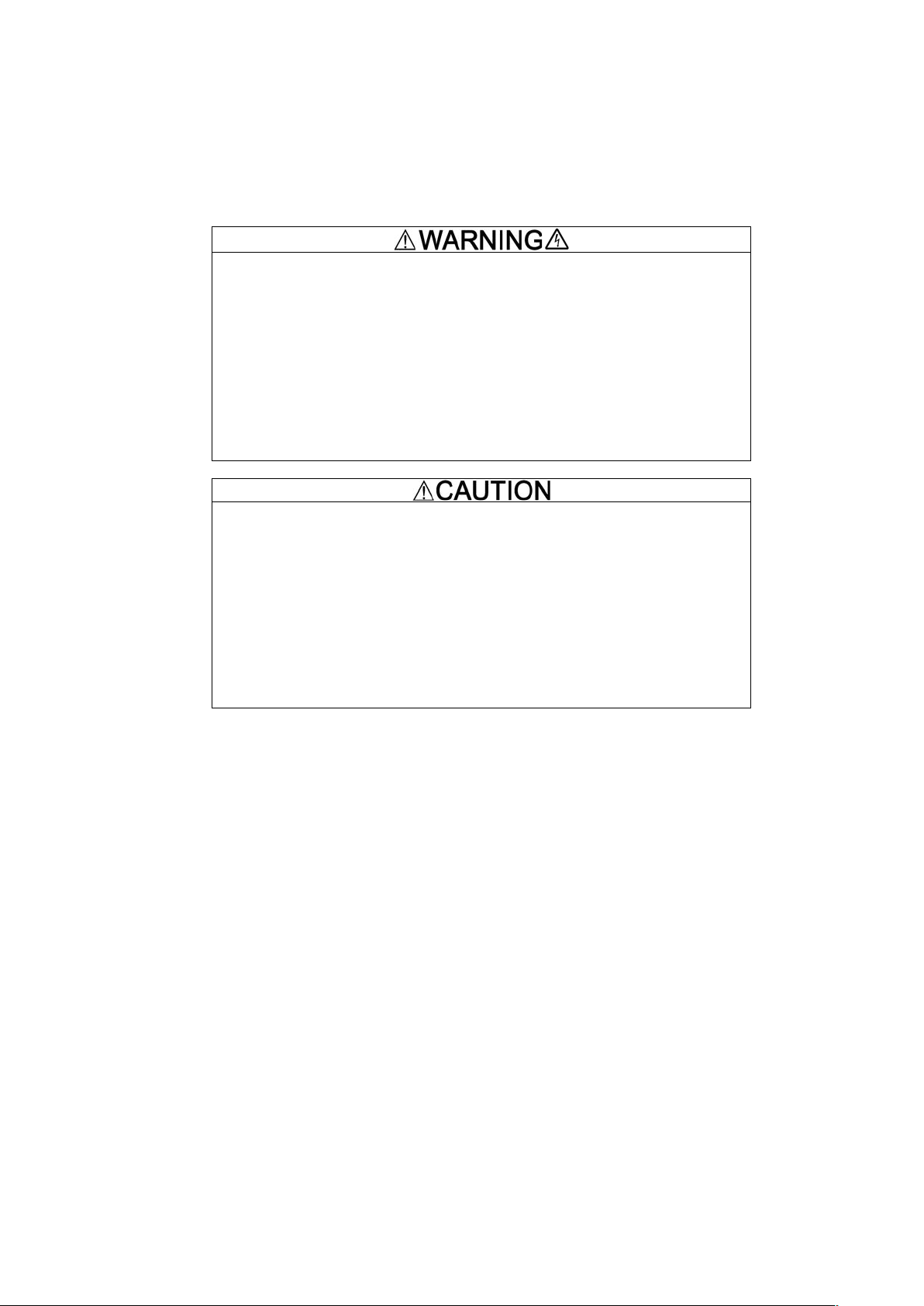
Safety precautions are classified into the following two categories in this manual.
Failure to heed the information indicated by this symbol may lead to
dangerous conditions, possibly resulting in death or serious bodily
injuries.
Failure to heed the information indicated by this symbol may lead to
dangerous conditions, possibly resulting in minor or light bodily injuries
and/or substantial property damage.
Failure to heed the information contained under the CAUTION title can also result in serious consequences.
These safety precautions are of utmost importance and must be observed at all times.
Application
• FRENIC-Lift is equipment designed to drive induction motors and synchronous motors for exclusively
controlling elevating machinery. Do not use it for single-phase motors or for other purposes.
Fire or an accident could occur.
• This product may not be used for a life-support system or other purposes directly related to the human
safety.
• Although product is manufactured under strict quality control, install safety devices for applications
where serious accidents or property damages are foreseen in relation to the failure of it.
An accident could occur.
Page 4

ii iii
Page 5
Installation
• Install the inverter on a base made of metal or other non-flammable material.
Otherwise, a fire could occur.
• Do not place flammable object nearby.
Doing so could cause fire.
• Do not support the inverter by its front cover during transportation.
Doing so could cause a drop of the inverter and injuries.
• Prevent lint, paper fibers, sawdust, dust, metallic chips, or other foreign materials from getting into the
inverter or from accumulating on the heat sink.
• When changing the positions of the top and bottom mounting bases, use only the specified screws.
Otherwise, a fire or an accident might result.
• Do not install or operate an inverter that is damaged or lacking parts.
Doing so could cause fire, an accident or injuries.
Wiring
• If there isn’t zero-phase current (Earth leakage current) detective device, such as a ground-fault relay
in the upstream power supply line, which is to avoid undesirable system shutdown. Install a
residual-current-operated protective device (RCD)/earth leakage circuit breaker (ELCB) individually to
break the individual inverter’s power supply line.
Otherwise, a fire could occur.
• When wiring the inverter to the power source, insert a recommended molded case circuit breaker
(MCCB) or residual-current-operated protective device (RCD)/earth leakage circuit breaker (ELCB)
(with overcurrent protection) in the path of each pair of power lines to inverters. Use the recommended
devices within the recommended current capacity.
• Use wires in the specified size.
• Tighten terminals with specified torque.
Otherwise, a fire could occur.
• When there is more than one combination of an inverter and motor, do not use a multicore cable for
the purpose of running their wirings together.
• Do not connect a surge killer to the inverter's output (secondary) circuit.
Doing so could cause a fire.
• Be sure to ground the inverter's grounding terminals
G.
Otherwise, an electric shock or a fire could occur.
• Qualified electricians should carry out wiring.
• Be sure to perform wiring after turning the power OFF.
Otherwise, an electric shock could occur.
• Be sure to perform wiring after installing the inverter unit.
Otherwise, an electric shock or injuries could occur.
Page 6
iv
• Ensure that the number of input phases and the rated voltage of the product match the number of
phases and the voltage of the AC power supply to which the product is to be connected.
Otherwise, a fire or an accident could occur.
• Do not connect the power supply wires to the inverter output terminals (U, V, and W).
Doing so could cause fire or an accident.
• In general, sheaths of the control signal wires are not specifically designed to withstand a high voltage
(i.e., reinforced insulation is not applied). Therefore, if a control signal wire comes into direct contact
with a live conductor of the main circuit, the insulation of the sheath might break down, which would
expose the signal wire to a high voltage of the main circuit. Make sure that the control signal wires will
not come into contact with live conductors of the main circuit.
Doing so could cause an accident or an electric shock.
• Before changing the switches, turn OFF the power and wait at least 10 minutes. Make sure that the
charging lamp is turned OFF. Further, make sure, using a multimeter or a similar instrument, that the
DC link bus voltage between the terminals P(+) and N(-) has dropped to the safe level (+25 VDC or
below).
Otherwise, an electric shock could occur.
• The inverter, motor and wiring generate electric noise. Be careful about malfunction of the nearby
sensors and devices. To prevent them from malfunctioning, implement noise control measures.
Otherwise an accident could occur.
• The leakage current of FRENIC-Lift is comparatively large for the EMC filter built-in type of inverters.
Be sure to perform protective grounding.
Otherwise, an accident or an electric shock could occur.
Operation
• Be sure to mount the front cover before turning the power ON. Do not remove the cover when the
inverter power is ON.
Otherwise, an electric shock could occur.
• Do not operate switches with wet hands.
Doing so could cause electric shock.
• If the auto-reset function has been selected, the inverter may automatically restart and drive the motor
depending on the cause of tripping. Design the machinery or equipment so that human safety is
ensured at the time of restarting.
Otherwise, an accident could occur.
• If any of the protective functions have been activated, first remove the cause. Then, after checking that
all the run commands are set to OFF, release the alarm. If the alarm is released while any run
commands are set to ON, the inverter may supply the power to the motor, running the motor.
Otherwise, an accident could occur.
Page 7
v
• If the user configures the function codes wrong without completely understanding this Instruction
Manual and the FRENIC-Lift LM2A series Reference Manual, the motor may rotate with a torque or at
a speed not permitted for the machine.
An accident or injuries could occur.
• Even if the inverter has interrupted power to the motor, if the voltage is applied to the main circuit input
terminals L1/R, L2/S and L3/T, voltage may be output to inverter output terminals U, V, and W.
• Even if the motor is stopped due to DC braking, voltage is output to inverter output terminals U, V, and
W.
An electric shock may occur.
• The inverter can easily accept high-speed operation. When changing the speed setting, carefully
check the specifications of motors or equipment beforehand.
Otherwise, injuries could occur.
• Do not touch the heat sink because it becomes very hot.
Doing so could cause burns.
• The DC brake function of the inverter does not provide any holding mechanism.
Injuries could occur.
• Ensure safety before modifying customizable logic related function code settings (U codes and related
function codes) or turning ON the "Cancel customizable logic" terminal command CLC. Depending
upon the settings, such modification or cancellation of the customizable logic may change the
operation sequence to cause a sudden motor start or an unexpected motor operation.
• If any abnormality is found in the inverter or motor, immediately stop it and perform troubleshooting,
referring to the FRENIC-Lift LM2A series Reference Manual.
An accident or injuries could occur.
Page 8
vi
Maintenance and inspection, and parts replacement
• Before proceeding to maintenance or inspection, turn OFF the power and wait at least 10 minutes.
Make sure that the charging lamp is turned OFF. Further, make sure, using a multimeter or a similar
instrument, that the DC link bus voltage between the terminals P(+) and N(-) has dropped to the safe
level (+25 VDC or below).
Otherwise, an electric shock could occur.
• Always carry out the daily and periodic inspections described in the this manual. Use of the inverterfor
long periods of time without carrying out regular inspections could result in malfunction or damage, and
an accident or fire could occur.
• It is recommended that periodic inspections be carryout every one to two years, however, they should
be carried out more frequently depending on the usage conditions.
• It is recommended that parts for periodic replacement be replaced in accordance with the standard
replacement frequency indicated in the this manual. Use of the product for long periods of timewithout
replacement could result in malfunction or damage, and an accident or fire could occur.
• Contact outputs [30A/B/C] [Y5A/C] [Y4A/C] [Y3A/C] use relays, and may remain ON, OFF, or
undetermined when their lifetime is reached. In the interests of safety, equip the inverter with an
external protective function.
Fire or an accident could occur.
• Maintenance, inspection, and parts replacement should be made only by qualified persons.
• Take off the watches, rings and other metallic objects before starting work.
• Use insulated tools.
Otherwise, an electric shock or injuries could occur.
• Never modify the inverter.
Doing so could cause an electric shock or injuries.
Disposal
• Treat the inverter as an industrial waste when disposing of it.
Otherwise injuries could occur.
GENERAL PRECAUTIONS
Drawings in this manual may be illustrated without covers or safety shields for explanation of detail parts.
Restore the covers and shields in the original state and observe the description in the manual before starting
operation.
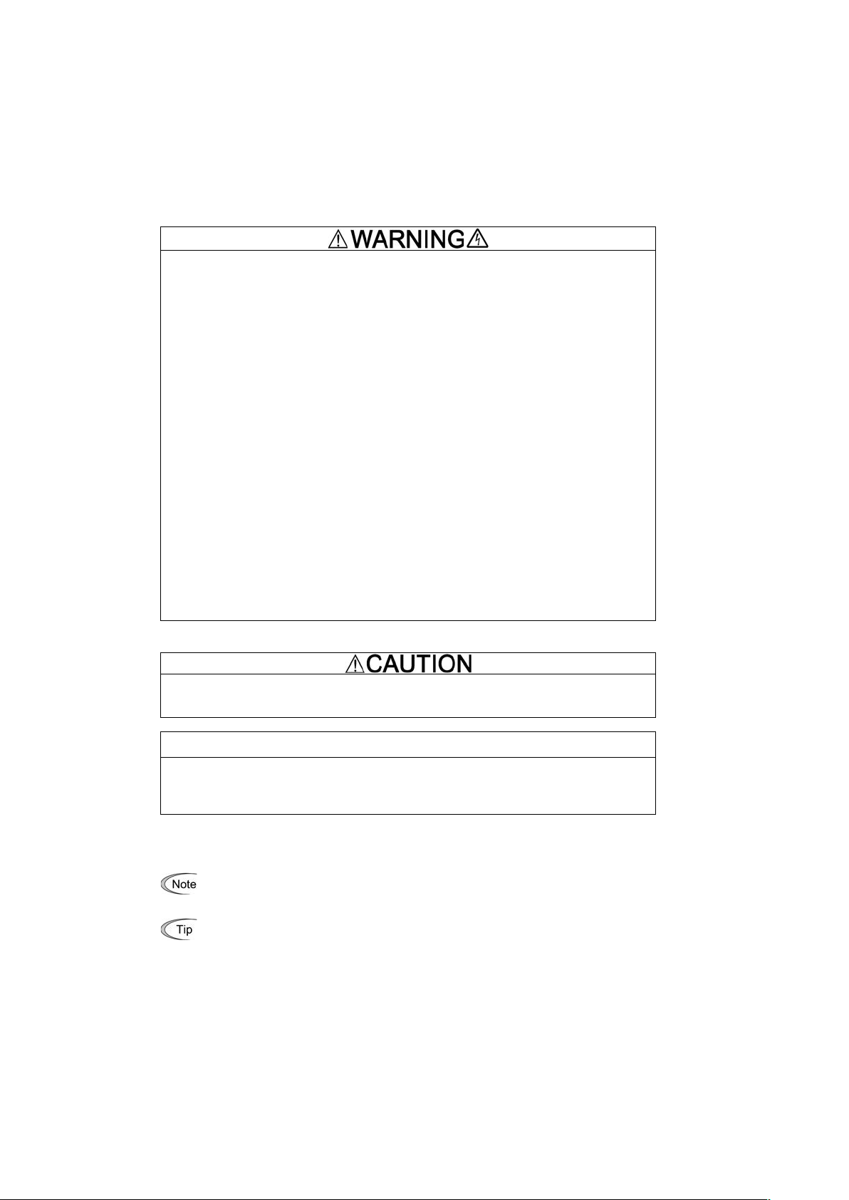
Icons
The following icons are used throughout this manual.
This icon indicates information which, if not heeded, can result in the inverter not operating to full
efficiency, as well as information concerning incorrect operations and settings which can result in
accidents.
This icon indicates information that can prove handy when performing certain settings or operations.
"
This icon indicates a reference to more detailed information.
Page 9
vii
Conformity to the Low Voltage Directive in the EU
If installed according to the guidelines given below, inverters marked with CE are considered as compliant with
the Low Voltage Directive.
Compliance with European Standards
Adjustable speed electrical power drive systems (PDS).
Part 5-1: Safety requirements. Electrical, thermal and energy. IEC/EN 61800-5-1
1. The ground terminal G should always be connected to the ground. Do not use only a
residual-current-operated protective device (RCD)/earth leakage circuit breaker (ELCB)* as the sole
method of electric shock protection. Be sure to use ground wires of recommended size listed on page vii.
*With overcurrent protection.
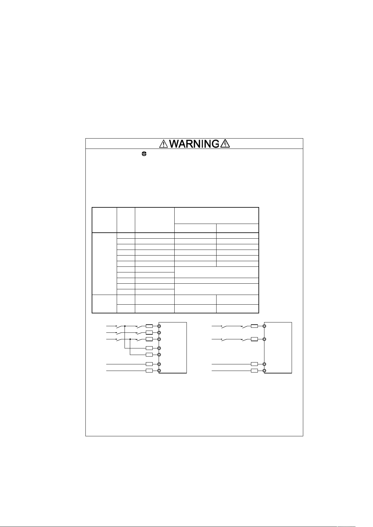
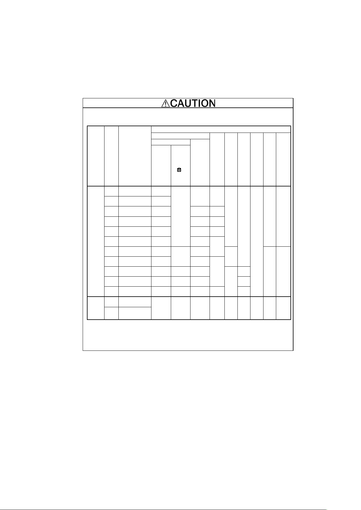
2. To prevent the risk of hazardous accidents that could be caused by damage of the inverter, install the
specified fuses in the supply side (primary side) according to the following tables.
- Breaking capacity: Min. 10 kA
- Rated voltage: Min. 500 V
Power
supply
voltage
Nominal
applied
motor (kW)
Inverter type
Fuse rating [A] (Class)
With DCR
Without DCR
Three-phase
400 V
2.2
FRN0006LM2A-4#
10 (IEC/EN 60269-2)
15 (IEC/EN 60269-2)
4.0
FRN0010LM2A-4#
15 (IEC/EN 60269-2)
20 (IEC/EN 60269-2)
5.5
FRN0015LM2A-4#
20 (IEC/EN 60269-2)
30 (IEC/EN 60269-2)
7.5
FRN0019LM2A-4#
30 (IEC/EN 60269-2)
40 (IEC/EN 60269-2)
11
FRN0025LM2A-4#
40 (IEC/EN 60269-2)
- *2
15
FRN0032LM2A-4#
60 (IEC/EN 60269-2)
- *2
18.5
FRN0039LM2A-4#
160 (IEC/EN 60269-4)
22
FRN0045LM2A-4#
30
FRN0060LM2A-4#
250 (IEC/EN 60269-4)
37
FRN0075LM2A-4#
315 (IEC/EN 60269-4)
45
FRN0091LM2A-4#
Single-
Phase
200V
2.2
FRN0011LM2A-7#
30 (IEC/EN 60269-2)
40 (IEC/EN 60269-2)
4.0
FRN0018LM2A-7#
60 (IEC/EN 60269-2)
80 (IEC/EN 60269-2)
.
L1/R
L2/S
L3/T
24V+
24V-
Fuses
Three-
Phase
400V
MC
Disconnect
MCCB
or
RCD/ELCB, etc.
( )
Power
supply
24VDC
(*1)
R0
T0
(*1)
L1/L
L2/N
24V+
24V-
Fuses
SinglePhase
200V
MC
Disconnect
MCCB
or
RCD/ELCB, etc.
( )
Power
supply
24VDC
(*1)
Note: A box (#) replaces an alphabetic letter depending on the shipping destination.
#Shipping destination: E (Europe) or A (Asia)
*1) Not more than 6A (RMS) fuses or not more than 5A (RMS) breakers for 24V power supply and
control power supply (R0 and T0). Fuse class: IEC/EN 60269-1 or 60269-2
*2) The recommended fuse type is applicable to the inverter equipped with a DC reactor only.
Be sure to use a DC reactor.
Page 10
viii
Conformity to the Low Voltage Directive in the EU (Continued)
3. When used with the inverter, a molded case circuit breaker (MCCB), residual-current-operated protective
device (RCD)/earth leakage circuit breaker (ELCB) or magnetic contactor (MC) should conform to the EN
or IEC standards.
4. When you use a residual-current-operated protective device (RCD)/earth leakage circuit breaker (ELCB)
for protection from electric shock in direct or indirect contact power lines or nodes, be sure to install type
B of RCD/ELCB on the input (primary) of the inverter.
5. The inverter should be used in an environment that does not exceed Pollution Degree 2 requirements. If
inverters are to be used in an environment with pollution Degree 3 or 4, place them in an enclosure of
IP54 or above.
6. Install the inverter, Reactor, input or output filter in an enclosure with minimum degree of protection of
IP2X (Top surface of enclosure shall be minimum IP4X when it can be easily accessed), to prevent
human body from touching directly to live parts of these equipment.
7. Do not connect any copper wire directly to grounding terminals. Use crimp terminals with tin or equivalent
plating to connect them.
8. When you use an inverter at an altitude of more than 2000 m, you should apply basic insulation for the
control circuits of the inverter. The inverter cannot be used at altitudes of more than 3000 m.
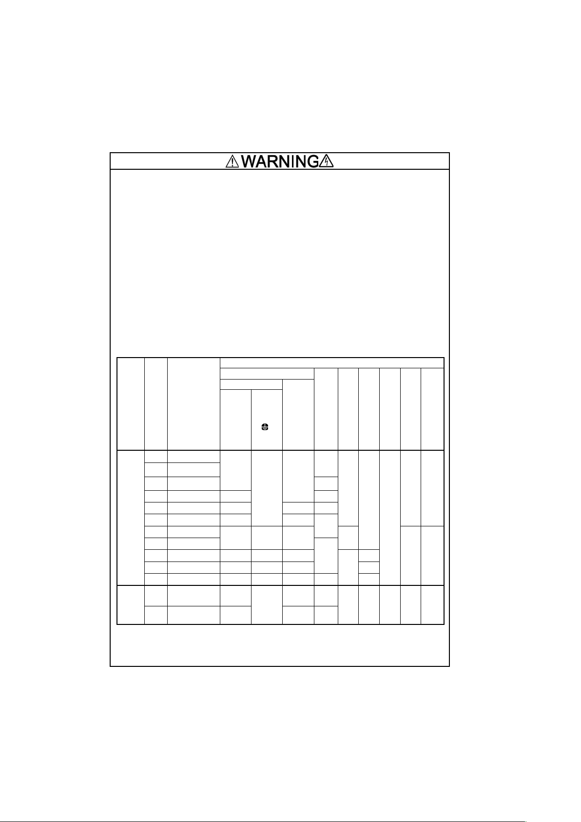
9. Use wires listed in IEC 60364-5-52.
Power supply
voltage
Nominal applied motor (kW)
Inverter type
Recommended copper wire size (mm2)
Main terminal *1
DC reactor connection
[P2,P3] [P1, P(+)] *1
External braking resistor
connection [DB, P(+)]*1
Inverter outputs for Short
circuit [U0,V0,W0] *1
Control circuit
control power
supply [24V+,-]
Aux main power supply
[R0, T0] *1
Main power input
Inverter
outputs
[U, V, W]
[L1/R,
L2/S,
L3/T]
Inverter’s
grounding
[
G]
Three-phase 400 V
2.2
FRN0006LM2A-4#
2.5
10
2.5
2.5
2.5
2.5
0.75
0.75
-
4.0
FRN0010LM2A-4#
5.5
FRN0015LM2A-4#
4
7.5
FRN0019LM2A-4#
4
6
11
FRN0025LM2A-4#
6 4 10
15
FRN0032LM2A-4#
10
6
16
18.5
FRN0039LM2A-4#
16
16
10
4
-
2.5
22
FRN0045LM2A-4#
25
30
FRN0060LM2A-4#
25
25
16
10
16
37
FRN0075LM2A-4#
35
35
25
25
45
FRN0091LM2A-4#
50
50
35
35
35
Single-
phase
200V
2.2
FRN0011LM2A-7#
4
10
2.5
4
2.5
2.5
0.75
0.75
-
4.0
FRN0018LM2A-7#
6
4
6
Note: A box (#) replaces an alphabetic letter depending on the shipping destination.
#Shipping destination: E (Europe) or A (Asia)
*1 The recommended wire size for main circuits is for the 70°C 600 V PVC sheath wires used at an ambient temperature of
40°C.
Page 11
ix
Conformity to the Low Voltage Directive in the EU (Continued)
10. The inverter has been tested according to IEC/EN 61800-5-1 Short-circuit Test under the following
conditions.
Short-circuit current in the supply: 10,000 A
480V or below (400V class series inverters)
240V or below (200V class series inverters)
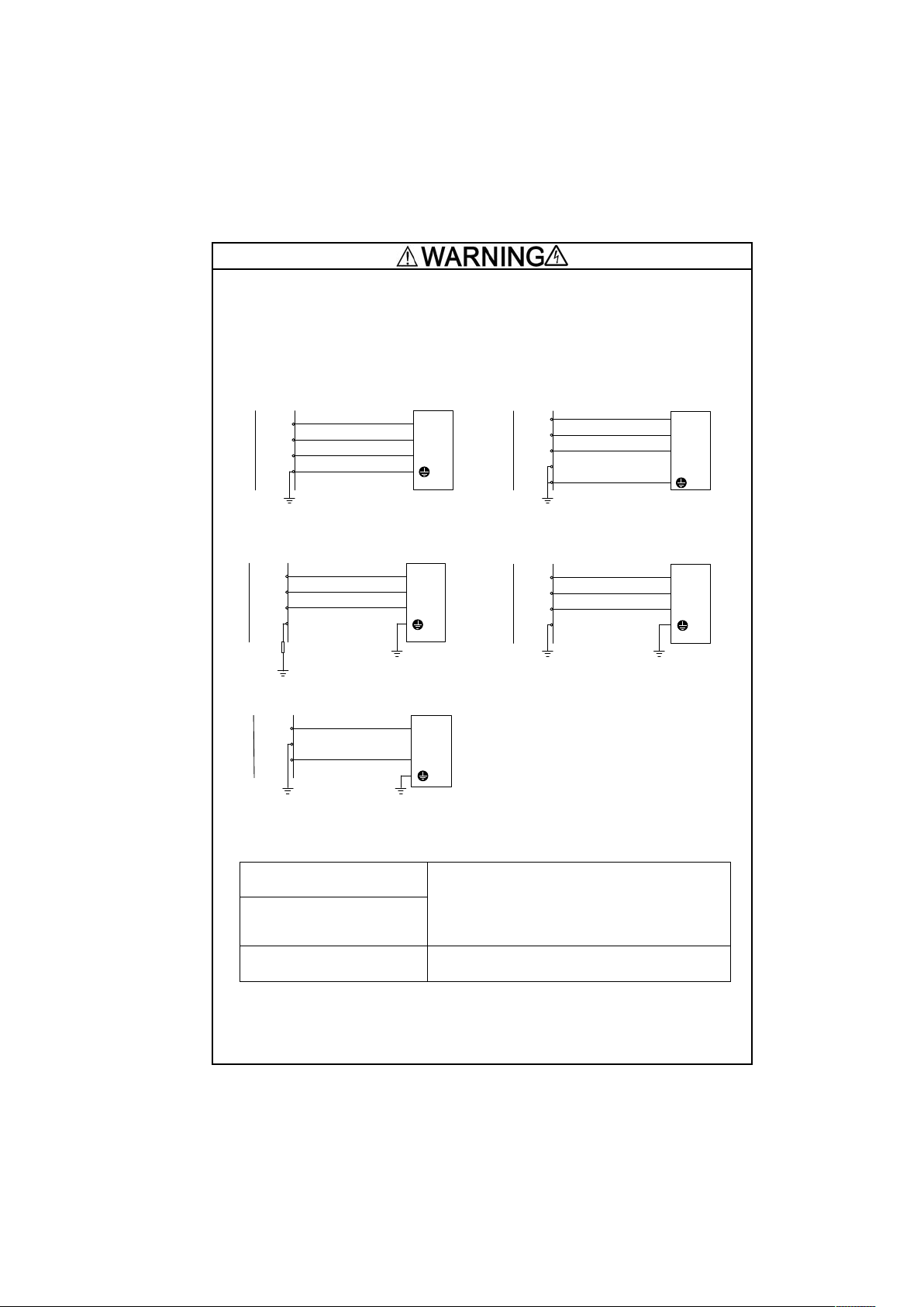
11. Use this inverter at the following power supply system.
L1
L2
L3
PEN
L1/R
L2/S
L3/T
G
Inverter
TN-C system
Power supply
L1
L2
L3
N
L1/R
L2/S
L3/T
Power Supply
TN-S system
PE
G
Inverter
L1
L2
L3
N
L1/R
L2/S
L3/T
Power supply
IT system *1)
G
Inverter
L1
L2
L3
N
L1/R
L2/S
L3/T
Power supply
TT system
(Earthed neutral)
G
Inverter
L1
L2
L3
L1/L
L3/N
Power supply
TT system
(corner earthed/phase-earthed)
(Applicable for 200V type only) *2)
G
Inverter
*1 Use this inverter at the following IT system.
Non-earthed (isolated from earth)
IT system
Can be used.
In this case the insulation between the control interface
and the main circuit of the inverter is basic insulation.
Thus do not connect SELV circuit from external controller
directly (make connection using a supplementary
insulation.).
IT system which earthed neutral
by an impedance
Corner earthed / Phase-earthed IT
system by an impedance
Cannot be used
*2 Cannot apply to Corner earthed / Phase-earthed TT system except 200V type.
L2
Page 12

x
Conformity with Canadian standards and U.S. standards
The inverters with CSA “C/US” marking are subject to the regulations set forth by the Canadian and U.S.
standards by installation within precautions listed below.
1. Solid state motor overload protection (motor protection by electronic thermal overload relay) is provided in
each model. Use function codes F10 to F12 to set the protection level.
2. Short circuit rating
Suitable for use on a circuit capable of delivering not more than 10,000 rms symmetrical amperes, 240
Volts maximum when protected by fuses having an interrupting rating not less than 10,000 rms
symmetrical amperes, 240 Volts maximum. Models FRN: rated for 200 V class input.
CONVIENT AUX CIRCUITS NON SUSCEPTIBLES DE DÉLIVRER PLUS DE 10,000 AMPÈRES
SYMÉTRIQUES EFF., MAXIMUM 240 V
Suitable for use on a circuit capable of delivering not more than 10,000 rms symmetrical amperes, 480
Volts maximum when protected by circuit breaker having an interrupting rating not less than 10,000 rms
symmetrical amperes, 480 Volts maximum. Models FRN: rated for 400 V class input.
CONVIENT AUX CIRCUITS NON SUSCEPTIBLES DE DÉLIVRER PLUS DE 10,000 AMPÈRES
SYMÉTRIQUES EFF., MAXIMUM 480 V
Branch Circuit Protection must be provided by the end user, sized per the Canadian Electrical Code, Part
I, the National Electrical Code and all applicable local codes.
INTEGRAL SOLID STATE SHORT CIRCUIT PROTECTION DOES NOT PROVIDE BRANCH CIRCUIT
PROTECTION. BRANCH CIRCUIT PROTECTION MUST BE PROVIDED IN ACCORDANCE WITH THE
CANADIAN ELECTRICAL CODE, PART I.
LA PROTECTION INTÉGRÉE CONTRE LES COURTSCIRCUITS N'ASSURE PAS LA PROTECTION
DE LA DÉRIVATION. LA PROTECTION DE LA DÉRIVATION DOIT ÊTRE EXÉCUTÉE
CONFORMÉMENT AU CODE CANADIEN DE L'ÉLECTRICITÉ, PREMIÈRE PARTIE.
3. Environmental Requirements
・Surrounding/ ambient temperature
Maximum Surrounding Air Temperature 45 °C
・Area of Use
For use in pollution degree 2 environments and overvoltage category III.
Page 13
xi
Conformity with Canadian standards and U.S. standards (Continued)
4. Use wires listed in CSA or UL.
Power supply
voltage
Nominal applied motor (kW)
Inverter type
Recommended copper wire size AWG (mm2)
Main terminal *1
DC reactor connection
[P2,P3] [P1, P(+)] *1
External braking resistor
connection [DB, P(+)]*1
Inverter outputs for Short
circuit [U0,V0,W0] *1
Control circuit
control power
supply [24V+,-]
Aux main power supply
[R0, T0] *1
Main power input
Inverter
outputs
[U, V, W]
[L1/R,
L2/S,
L3/T]
Inverter’s
grounding
[
G]
Three-phase 400 V
2.2
FRN0006LM2A-4#
14
(2.5)
6
(10)
14
(2.5)
14
(2.5)
14
(2.5)
14
(2.5)
18
(0.75)
18
(0.75)
-
4.0
FRN0010LM2A-4#
12
(2.5)
5.5
FRN0015LM2A-4#
10
(2.5)
12
(2.5)
10
(4)
7.5
FRN0019LM2A-4#
10
(4)
10
(2.5) 8 (6)
11
FRN0025LM2A-4#
8
(6) 8 (4) 6 (10)
15
FRN0032LM2A-4#
6
(10) 8 (6)
4
(16)
18.5
FRN0039LM2A-4#
6
(16)
4
(16)
8
(10)
10
(4)
-
12
(2.5)
22
FRN0045LM2A-4#
4
(16) 6 (10)
3
(25)
30
FRN0060LM2A-4#
3
(25) 3 (25) 4 (16)
6
(10)
4
(16)
37
FRN0075LM2A-4#
1
(35) 1 (35) 3 (25) 3 (25)
45
FRN0091LM2A-4#
1/0
(50)
1/0
(50) 2 (35) 1 (35) 1 (35)
Single-
phase
200 V
2.2
FRN0011LM2A-7#
10
(5.3) 8 (8.4)
12
(3.3)
10
(5.3)
14
(2.1)
14
(2.1)
18
(0.8)
18
(0.8)
-
4.0
FRN0018LM2A-7#
Note: A box (#) replaces an alphabetic letter depending on the shipping destination.
#Shipping destination: E (Europe) or A (Asia)
*1 Use Cu wire only. The recommended wire size for main circuits is for the 75 °C.
Page 14
xii
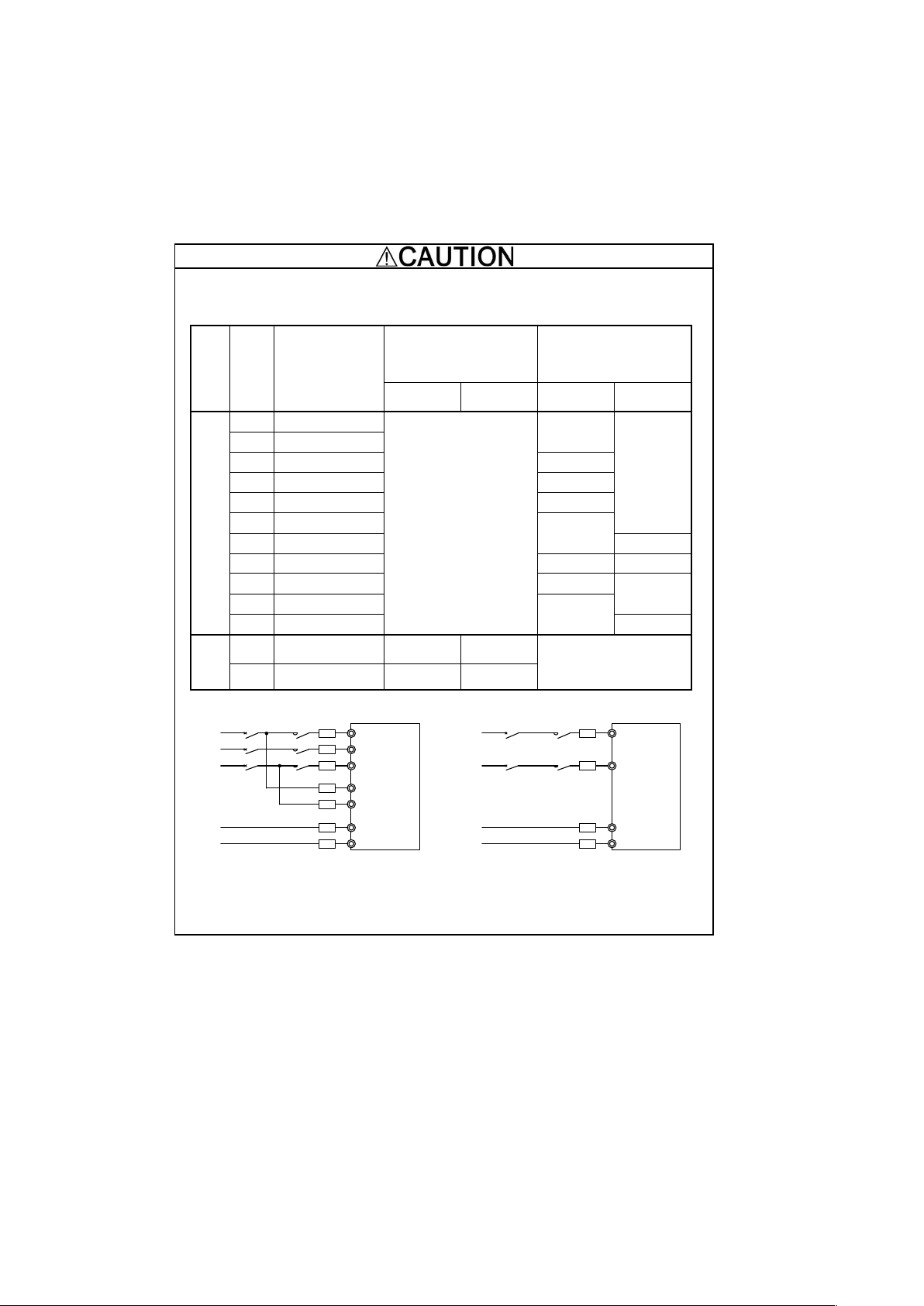
Conformity with Canadian standards and U.S. standards (Continued)
5. Install CSA or UL certified fuses or Circuit breaker between the power supply and the inverter, referring to
the table below.
Power supply
voltage
Nominal
applied
motor (kW)
Inverter type
Fuse rating [A]
(Class)
Circuit breaker (MCCB)
or
RCD/ELCB etc
[A]
With
DCR
Without
DCR
With
DCR
Without
DCR
Three-phase 400 V
2.2
FRN0006LM2A-4#
-
10
-
4.0
FRN0010LM2A-4#
5.5
FRN0015LM2A-4#
15
7.5
FRN0019LM2A-4#
20
11
FRN0025LM2A-4#
30
15
FRN0032LM2A-4#
40
18.5
FRN0039LM2A-4#
75
22
FRN0045LM2A-4#
50
100
30
FRN0060LM2A-4#
75
125
37
FRN0075LM2A-4#
100
45
FRN0091LM2A-4#
150
Single-
Phase
200V
2.2
FRN0011LM2A-7#
30
(Class J)
40
(Class J)
-
4.0
FRN0018LM2A-7#
60
(Class J)
80
(Class J)
L1/R
L2/S
L3/T
24V+
24V-
Fuses
Three-
Phase
400V
MC
Disconnect
MCCB
or
RCD/ELCB, etc.
( )
Power
supply
24VDC
(*1)
R0
T0
(*1)
L1/L
L2/N
24V+
24V-
Fuses
SinglePhase
200V
MC
Disconnect
MCCB
or
RCD/ELCB, etc.
( )
Power
supply
24VDC
(*1)
Note: A box (#) replaces an alphabetic letter depending on the shipping destination.
#Shipping destination: E (Europe) or A (Asia)
*1) Not more than 6A (RMS) fuses or not more than 5A (RMS) breakers for 24V power supply and control power supply (R0 and
T0).
Page 15

xiii
Product warranty
To all our customers who purchase Fuji Electric products included in this documentation:
Please take the following items into consideration when placing your order.
When requesting an estimate and placing your orders for the products described in this document, please be
aware that any items such as specifications which are not specifically mentioned in the contract, catalog,
specifications or other materials will be as mentioned below.
In addition, the products described in this document are limited in the use they are put to and the place where
they can be used, etc., and may require periodic inspection. Please confirm these points with your sales
representative or directly with this company.
Furthermore we request that you inspect the purchased and delivered products at the time of delivery. Also,
prepare the area for installation of the inverter.
[ 1 ] Free of charge warranty period and warranty range
(1) Free of charge warranty period
1) The product warranty period is ''1 year from the date of purchase'' or 24 months from the
manufacturing date imprinted on the nameplate, whichever date is earlier.
2) However, in cases where the installation environment, conditions of use, frequency or use and times
used, etc., have an effect on product life, this warranty period may not apply.
3) Furthermore, the warranty period for parts repaired by Fuji Electric's Service Department is ''6
months from the date that repairs are completed.''
(2) Warranty range
1) In the event that breakdown occurs during the product's warranty period which is the responsibility of
Fuji Electric, Fuji Electric will replace or repair the part of the product that has broken down free of
charge at the place where the product was purchased or where it was delivered. However, if the
following cases are applicable, the terms of this warranty may not apply.
The breakdown was caused by the installation conditions, environment, handling or methods of
use, etc. which are not specified in the catalog, operation manual, specifications or other relevant
documents.
The breakdown was caused by a product other than the purchased or delivered Fuji's product.
The breakdown was caused by ta product other than Fuji's product, such as the customer's
equipment or software design, etc.
Concerning the Fuji's programmable products, the breakdown was caused by a program other
than a program supplied by this company, or the results from using such a program.
The breakdown was caused by modifications or repairs affected by a party other than Fuji
Electric.
The breakdown was caused by improper maintenance or replacement of replaceable items, etc.
specified in the operation manual or catalog, etc.
The breakdown was caused by a scientific or technical or other problem that was not foreseen
when making practical application of the product at the time it was purchased or delivered.
The product was not used in the manner the product was originally intended to be used.
The breakdown was caused by a reason which Fuji Electric is not responsible, such as lightning
or other disaster.
2) Furthermore, the warranty specified herein shall be limited to the purchased or delivered product
alone.
3) The upper limit for the warranty range shall be as specified in item (1) above and any damages
(damage to or loss of machinery or equipment, or lost profits from the same, etc.) consequent to or
resulting from breakdown of the purchased or delivered product shall be excluded from coverage by
this warranty.
(3) Trouble diagnosis
As a rule, the customer is requested to carry out a preliminary trouble diagnosis. However, at the
customer's request, this company or its service network can perform the trouble diagnosis on a
chargeable basis. In this case, the customer is asked to assume the burden for charges levied in
accordance with this company's fee schedule.
Page 16

xiv
Product warranty
Page 17

xv
[ 2 ] Exclusion of liability for loss of opportunity, etc.
Regardless of whether a breakdown occurs during or after the free of charge warranty period, this company
shall not be liable for any loss of opportunity, loss of profits, or damages arising from special circumstances,
secondary damages, accident compensation to another company, or damages to products other than this
company's products, whether foreseen or not by this company, which this company is not be responsible for
causing.
[ 3 ] Repair period after production stop, spare parts supply period (holding period)
Concerning models (products) which have gone out of production, this company will perform repairs for a
period of 7 years after production stop, counting from the month and year when the production stop occurs. In
addition, we will continue to supply the spare parts required for repairs for a period of 7 years, counting from
the month and year when the production stop occurs. However, if it is estimated that the life cycle of certain
electronic and other parts is short and it will be difficult to procure or produce those parts, there may be cases
where it is difficult to provide repairs or supply spare parts even within this 7-year period. For details, please
confirm at our company's business office or our service office.
[ 4 ] Transfer rights
In the case of standard products which do not include settings or adjustments, the products shall be
transported to and transferred to the customer and this company shall not be responsible for local
adjustments or trial operation.
[ 5 ] Service contents
The cost of purchased and delivered products does not include the cost of dispatching engineers or service
costs. Depending on the request, these can be discussed separately.
[ 6 ] Applicable scope of service
Above contents shall be assumed to apply to transactions and use in the country where you purchased the
products.
Consult your local supplier or Fuji Electric representative for details.
Page 18

xvi
Table of Contents
Preface ................................................................................... i
! Safety precautions ............................................................. i
Conformity to the Low Voltage Directive in the EU .............. vi
Conformity with Canadian standards and U.S. standards ... ix
Chapter 1 BEFORE USE ................................................. 1-1
1.1 Acceptance Inspection and Appearance of
Product ................................................................... 1-1
1.2 Precautions for Using Inverters .............................. 1-3
1.3 Usage environment and Storage environment ....... 1-3
1.3.1 Usage environment ........................................ 1-4
1.3.2 Storage environment ..................................... 1-6
Chapter 2 MOUNTING AND WIRING THE INVERTER .. 2-1
2.1 Installing the Inverter .............................................. 2-1
2.2 Wiring ..................................................................... 2-2
2.2.1 Removing the front cover .............................. 2-2
2.2.2 Mounting the front cover ................................ 2-2
2.2.3 Recommended wire sizes .............................. 2-3
2.2.4 Terminal arrangement diagrams and screw
specifications ................................................. 2-3
2.2.5 Terminal functions and wiring order ............... 2-7
2.2.6 Connection diagrams ................................... 2-12
2.2.7 Setting the slide switches on the control PCB
..................................................................... 2-16
2.2.8 Mounting and connecting the keypad to
the panel ...................................................... 2-16
Chapter 3 OPERATION USING THE KEYPAD ............... 3-1
Chapter 4 RUNNING THE MOTOR FOR A TEST ........... 4-1
4.1 Checking Prior to Powering ON .............................. 4-1
4.2 Powering ON and Checking ................................... 4-1
4.3 Configuring the Function Code Data Before
Test Run ................................................................. 4-2
4.4 Running the Inverter for Motor Operation Check .... 4-3
4.5 Preparation for Practical Operation ........................ 4-3
Chapter 5 TROUBLESHOOTING .................................... 5-1
5.1 Alarm Codes ........................................................... 5-1
Chapter 6 MAINTENANCE AND INSPECTION .............. 6-1
6.1 Daily Inspection ...................................................... 6-1
6.2 Periodic Inspection ................................................. 6-1
6.3 List of Periodic Replacement Parts ........................ 6-2
6.4 Inquiries about Product and Guarantee .................. 6-3
6.4.1 When making an inquiry ................................ 6-3
Chapter 7 SPECIFICATIONS .......................................... 7-1
7.1 Standard Model ...................................................... 7-1
7.2 External Dimensions ............................................... 7-6
Chapter 8 CONFORMITY WITH STANDARDS ............... 8-1
8.1 Compatibility with Revised EMC Directive
and Low Voltage Directive ..................................... 8-1
8.2 Compliance with European Standards ................... 8-2
8.3 Conformity to the Low Voltage Directive
in the EU ................................................................. 8-2
8.4 Compliance with EMC Standards ........................... 8-3
8.4.1 General .......................................................... 8-3
8.4.2 Recommended installation procedure ........... 8-3
8.4.3 Leakage current of the EMC filter .................. 8-4
8.5 Harmonic Component Regulation in the EU ........... 8-5
8.5.1 General comments ........................................ 8-5
8.5.2 Compliance with IEC/EN 61000-3-2 .............. 8-5
8.6 Compliance with Functional Safety Standard ......... 8-6
8.6.1 General .......................................................... 8-6
8.6.2 Notes for compliance to Functional Safety
Standard ....................................................... 8-8
8.6.3 Inverter output state when Safe Torque Off
(STO) is activated ....................................... 8-10
8.6.4 ECF alarm (caused by logic discrepancy) and
inverter output state .................................... 8-12
8.7 Compliance with Canadian and U.S. Standards
(CSA certification) ................................................. 8-13
8.7.1 General ........................................................ 8-13
8.7.2 Considerations when using FRENIC-Lift (LM2A)
in systems to be certified by CSA ................ 8-13
Page 19

xvii
MEMO
Page 20
1-1
Chapter 1 BEFORE USE
1.1 Acceptance Inspection and Appearance of Product
Unpack the package and check the following:
(1) An inverter and the following accessories are contained in the package.
Instruction manual (this book)
Main circuit wiring connector
(2) The inverter has not been damaged during transportation—there should be no dents or parts missing.
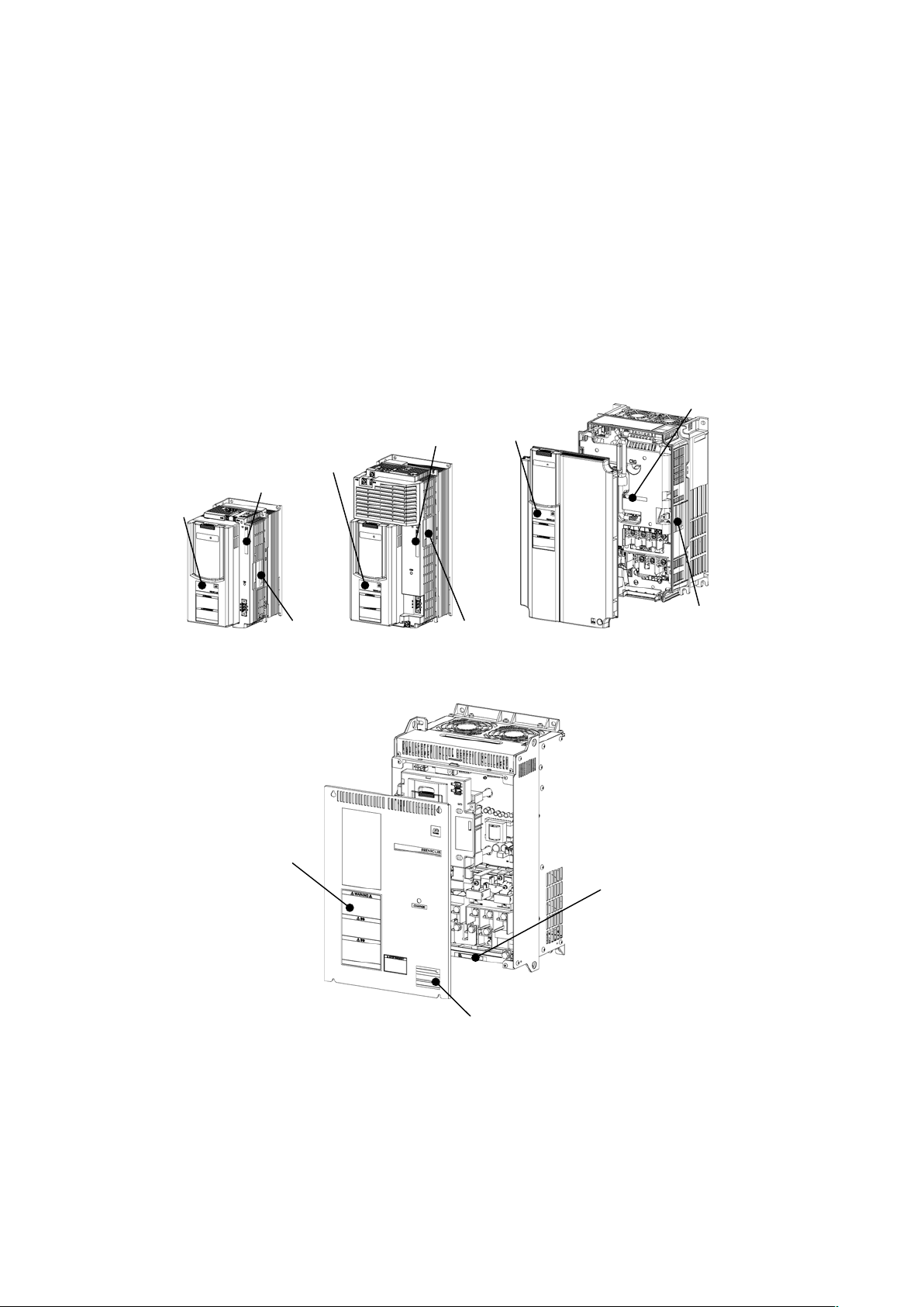
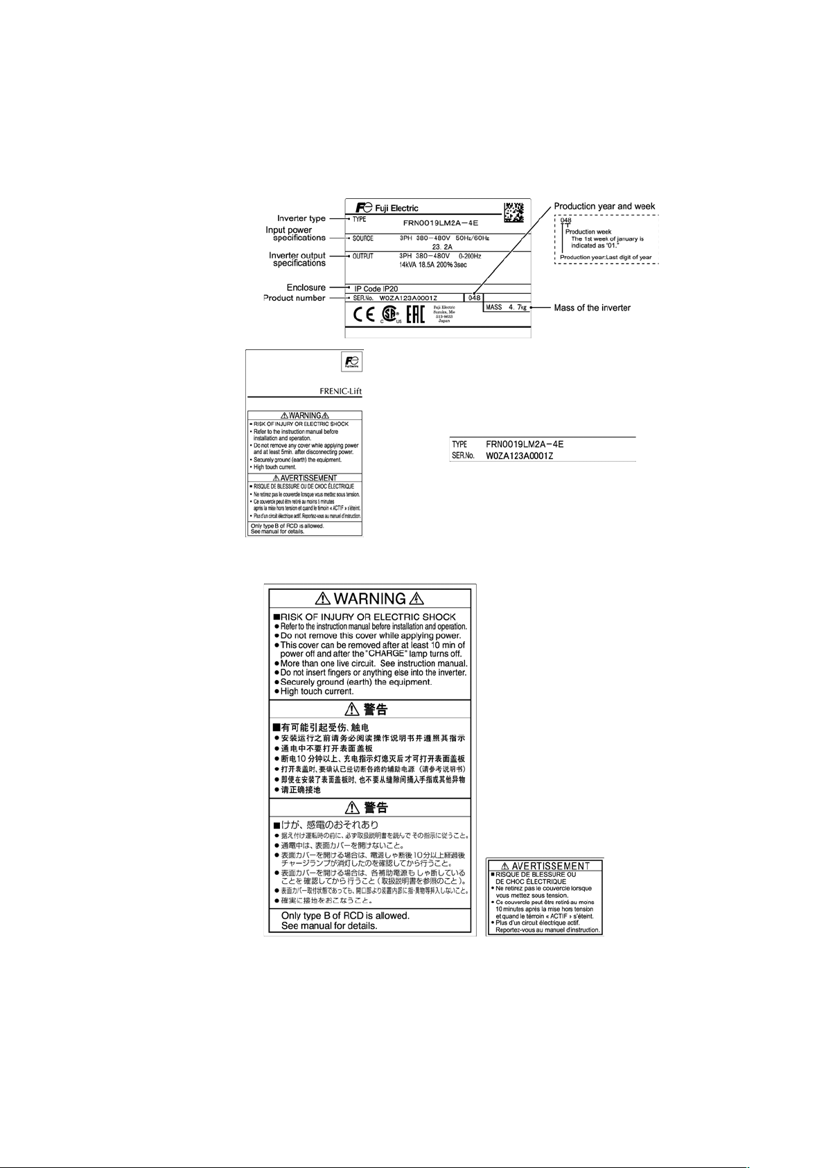
(3) The inverter is the type you ordered. You can check the type and specifications on the main nameplate. (A
total of two nameplates and warning plates are attached to the inverter as shown below.)
(FRN0011LM2A-7□/FRN0018LM2A-7□)
(FRN0006LM2A-4□toFRN0019LM2A-4□)
(FRN0025LM2A-4□/FRN0032LM2A-4□)
(FRN0039LM2A-4□/FRN0045LM2A-4□)
Warning plate
Sub nameplate
Main nameplate
Warning plate
Sub nameplate
Main nameplate
Warning plate
Sub nameplate
Main nameplate
(FRN0060LM2A-4□toFRN0091LM2A-4□)
Warning plate
Sub nameplate
Main nameplate
Page 21
1-2
Sub nameplate
Main nameplate
Warning plate
(FRN0060LM2A-4□toFRN0091LM2A-4□)
Warning plate
(FRN0011LM2A-7□/FRN0018LM2A-7□)
(FRN0006LM2A-4□toFRN0045LM2A-4□)
Page 22
1-3
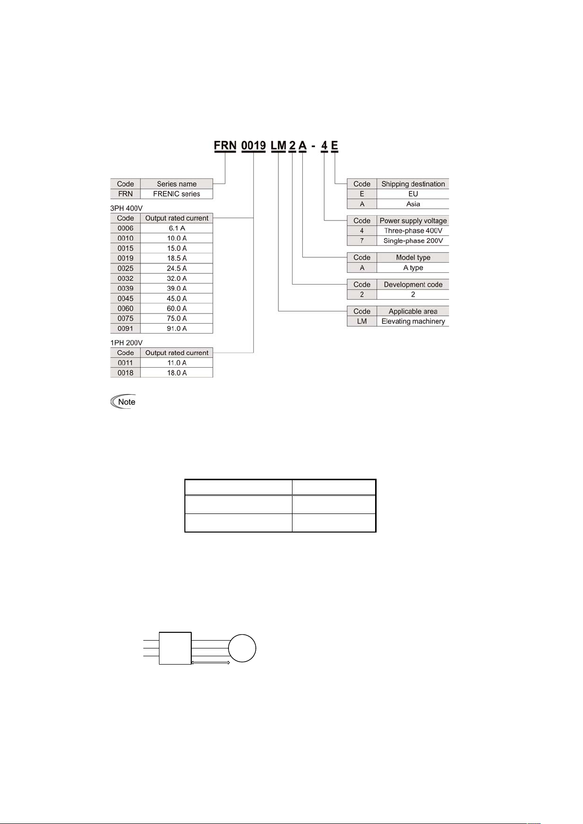
In this manual, inverter types are denoted as "FRN_ _ _LM2A- _!." The boxes ! replace alphabetic
letters depending on the shipping destination.
If you suspect the product is not working properly or if you have any questions about your product, contact your
Fuji Electric representative.
PG interface card is available to the following ROM versions.
"
For detailed on how to check the ROM version, refer to the FRENIC-Lift LM2A series Reference Manual.
Table 1.1 PG interface card, and ROM Versions
PG interface card
ROM Versions
OPC-PR/PS/PSH
0300 or later
OPC-PG3/PMPG
0600 or later
1.2 Precautions for Using Inverters
When handling inverters, be sure to observe the wiring precautions given below.
(1) The maximum wiring distance between an inverter and a motor
The maximum wiring is 20m.
When using wire longer than the specification, that may not be able to control a motor.
If longer secondary wiring is required, consult your Fuji Electric representative.
MotorInverter
Power
input
Max. 20 m
Page 23

1-4
1.3 Usage environment and Storage environment
This section provides precautions when handling inverters, e.g. precautions for installation environment and
storage environment.
1.3.1 Usage environment
Install the inverter in an environment that satisfies the requirements listed in Table below.
Environmental Requirements
Site location
Indoors
Ambient temperature
-10 to +45°C
Relative humidity
5 to 95% (No condensation)
Atmosphere
The inverter must not be exposed to dust, direct sunlight, corrosive gases, flammable gases, oil
mist, vapor or water drops. Pollution degree 2 (IEC/EN 60664-1) (*1)
The atmosphere can contain a small amount of salt. (0.01 mg/cm2 or less per year)
The inverter must not be subjected to sudden changes in temperature that will cause condensation
to occur.
Altitude
1,000 m max. (*2)
Atmospheric pressure
86 to 106 kPa
Vibration
3mm : 2 to less than 9Hz
9.8 m/s
2
: 9 to less than 20 H z
2 m/s
2
: 20 to less than 55 Hz
1 m/s
2
: 55 to less than 200 Hz
(*1) Do not install the inverter in an environment where it may be exposed to lint, cotton waste or moist dust or dirt which will clog the heat sink
of the inverter. If the inverter is to be used in such an environment, install it in a dustproof panel of your system.
(*2) If you use the inve rter in an altitude above 1000 m, yo u should apply an output current de rating factor as listed in the table below.
Altitude
1000 m or
lower
1000 to 1500 m
1500 to 2000 m
2000 to 2500 m
2500 to 3000 m
Output current derating factor
1.00
0.97
0.95
0.91
0.88
Page 24

1-5
1.3.2 Storage environment
The storage environment in which the inverter should be stored after purchase differs from the usage
environment. Store the inverter in an environment that satisfies the requirements listed below.
[1] Temporary storage
Table1.1 Storage and Transport Environments
Item
Specifications
Storage temperature *1
During transport: -25 to +70°C
Places not subjected to
abrupt temperature
changes or condensation
or freezing
During storage: -25 to +65°C
Relative humidity
5 to 95% RH *2
Atmosphere
The inverter must not be exposed to dust, direct sunlight, corrosive or flammable
gases, oil mist, vapor, water drops or vibration. The atmosphere must contain only
a low level of salt (0.01 mg/cm2 or less per year).
Atmospheric pressure
86 to 106 kPa (during storage)
70 to 106 kPa (during transportation)
*1 Assuming comparatively short time storage, e.g., during transportation or the like.
*2 Even if the humidity is within the specified requirements, avoid such places where the inverter will be
subjected to sudden changes in temperature that will cause condensation or freezing.
Precautions for temporary storage
(1) Do not leave the inverter directly on the floor.
(2) If the environment does not satisfy the specified requirements listed in Table1.1 wrap the inverter in an
airtight vinyl sheet or the like for storage.
(3) If the inverter is to be stored in a high-humidity environment, put a drying agent (such as silica gel) in the
airtight package described in (2) above.
[2] Long-term storage
The long-term storage method of the inverter varies largely according to the environment of the storage site.
General storage methods are described below.
(1) The storage site must satisfy the requirements specified for temporary storage.
However, for storage exceeding three months, the surrounding temperature range should be within the
range from -10 to +30°C. This is to prevent electrolytic capacitors in the inverter from deterioration.
(2) The package must be airtight to protect the inverter from moisture. Add a drying agent inside the package
to maintain the relative humidity inside the package within 70%.
(3) If the inverter has been installed to the equipment or panel at construction sites where it may be subjected
to humidity, dust or dirt, then temporarily remove the inverter and store it in the environment specified in
Table1.1.
Precautions for storage over 1 year
If the inverter has not been powered on for a long time, the property of the electrolytic capacitors may
deteriorate. Power the inverters on once a year and keep the inverters powered on for 30 to 60 minutes. Do not
connect the inverters to the load circuit (secondary side) neither run the inverter.
Page 25

2-1
Chapter 2 MOUNTING AND WIRING THE INVERTER
2.1 Installing the Inverter
(1) Mounting base
Install the inverter on a base made of metal or other non-flammable
material. Do not mount the inverter upside down or horizontally.
(2) Clearances
Ensure that the minimum clearances indicated in Figure 2.1 and Table
2.1 are maintained at all times. When installing the inverter in the panel
of your system, take extra care with ventilation inside the panel as the
ambient temperature easily rises. Do not install the inverter in a small
panel with poor ventilation.
! When mounting two or more inverters
When mounting two or more inverters in the same unit or panel,
basically lay them out side by side. When mounting them one above
the other, be sure to separate them with a partition plate or the like so
that any heat radiating from one inverter will not affect the one(s)
above.
Table 2.1 Clearances mm (inch)
Inverter capacity
A B C
D *1
200Vclass series:FRN0011LM2A-7□
FRN0018LM2A-7□
400Vclass series:FRN0006LM2A-4□ to
FRN0032LM2A-4□
0
(0)
10
(0.39)
100
(3.9)
0
(0)
FRN0039LM2A-4□to
FRN0045LM2A-4□
10
(0.39)
10
(0.39)
100
(3.9) 0 (0)
FRN0060LM2A-4□ to FRN0091LM2A-4□
50
(1.97)
50
(1.97)
100
(3.9)
100
(3.9)
*1) D: Space required in front of the inverter unit
Figure 2.1 Mounting Direction and
Required Clearances
Page 26
2-2
2.2 Wiring
Follow the procedure below. In the following description, it is assumed that the inverter has already been
installed.
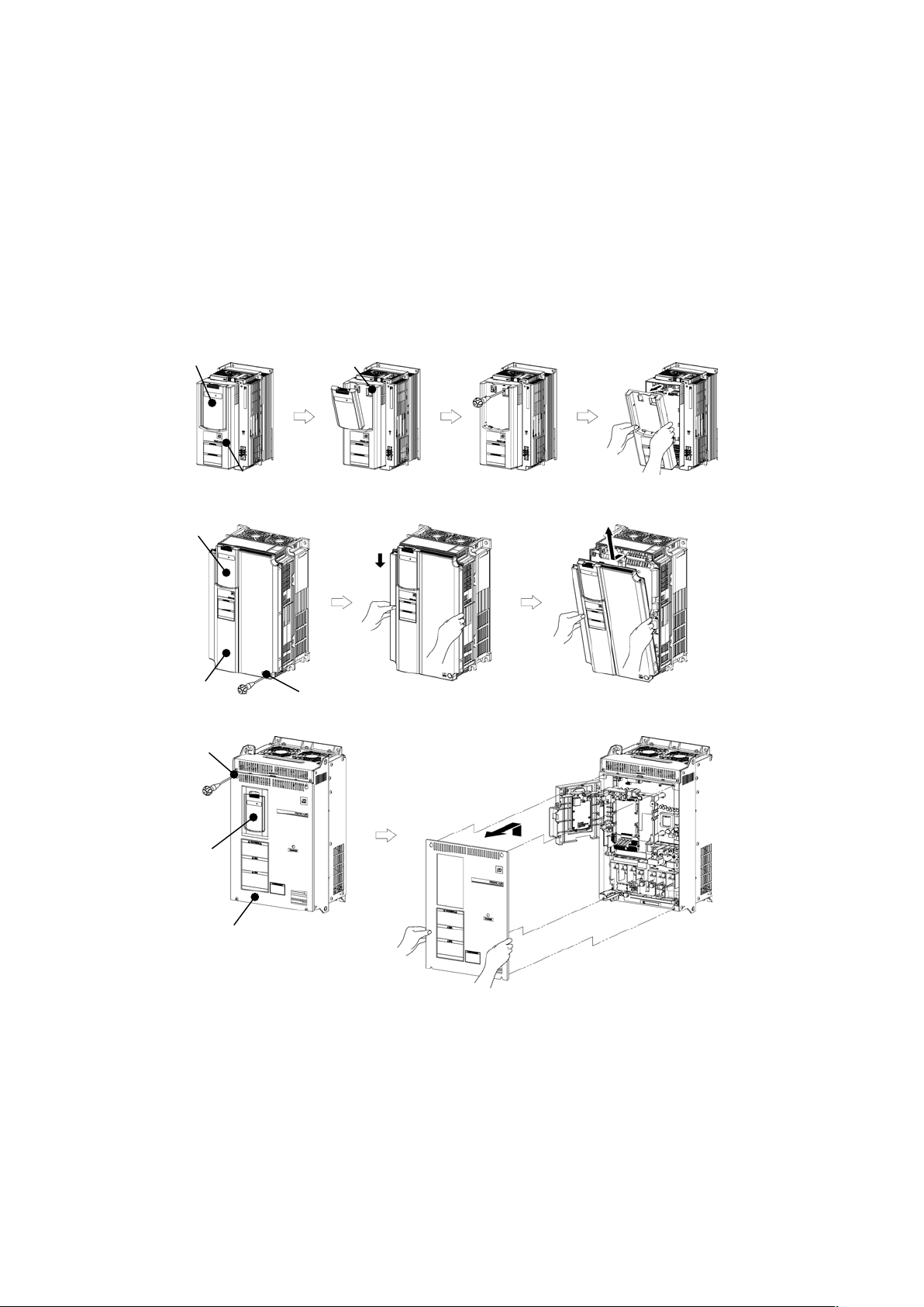
2.2.1 Removing the front cover
Remove the keypad blind cover and loosen the screws
Hold the right and left ends of the front cover and remove it.
Figure 2.2 Removing the Front Cover
(FRN0011LM2A-7 / FRN0018LM2A-7□, FRN0006LM2A-4□to FRN0032LM2A-4□)
2.2.2 Mounting the front cover
After wiring, mount the front cover back into place.
(Tightening torque: 1.8N・m)
Blind cover
Front cover
Screw
(FRN0011LM2A-7□/FRN0018LM2A-7□,FRN0006LM2A-4□toFRN0032LM2A-4□)
(FRN0039LM2A-4□/FRN0045LM2A-4□)
Blind cover
Front cover
Screw
(FRN0060LM2A-4□toFRN0091LM2A-4□)
Blind cover
Front cover
Screw
Page 27

2-3
2.2.3 Recommended wire sizes
For the recommended wire sizes for the main circuits, refer to the "Conformity to the Low Voltage Directive in
the EU" given in Preface. Terminals for the main circuits should have insulation, insulation tubes, or similar
treatment.
2.2.4 Terminal arrangement diagrams and screw specifications
The tables and figures given below show the screw specifications and terminal arrangement diagrams. Note
that the terminal arrangements differ depending on the inverter capacity.
(1) Main circuit terminals
Table 2.2 Main Circuit Terminals(kW rating)
Power supply
voltage
Nominal
applied motor
(kW)
Inverter type
Input/Output/
Main circuit
terminals
Short circuit
terminals
24VDC input
terminals *1,
Aux main
power supply
Grounding
terminals
Screw
size
Tightening
torque
(N·m)
Screw
size
Tightening
torque
(N·m)
Screw
size
Tightening
torque
(N·m)
Screw
size
Tightening
torque
(N·m)
Three-
phase 400V
2.2
FRN0006LM2A-4"
M3.5
1.0
M3.5
1.0
M2.5
0.27
M4
1.8
4.0
FRN0010LM2A-4"
5.5
FRN0015LM2A-4"
7.5
FRN0019LM2A-4"
11
FRN0025LM2A-4"
M4.5
1.2
M5
3.5
15
FRN0032LM2A-4"
18.5
FRN0039LM2A-4"
M6
5.8 - -
M3.5
1.2
M6
5.8
22
FRN0045LM2A-4"
30
FRN0060LM2A-4"
M8
13.5 - -
M8
13.5
37
FRN0075LM2A-4"
45
FRN0091LM2A-4"
Single-
phase 200V
2.2
FRN0011LM2A-7"
M3.5
1.0
M3.5
1.0
M2.5
0.27
M4
1.8
4.0
FRN0018LM2A-7"
M5
3.5
Page 28

2-4
◆ FRN0011LM2A-7□/FRN0018LM2A-7□,FRN0006LM2A-4□to FRN0019LM2A-4□
※Do not wire FRN0011LM2A-7□
◆ FRN0025LM2A-4□/FRN0032LM2A-4□
.
24VDC input terminals
Grounding terminals
Input terminals
Output terminals
Main circuit terminals
Short circuit terminals
24VDC input
terminals
Input
terminals
Grounding
terminals
Main circuit
terminals
Output
terminals
Short circuit
terminals
※
24VDC input
terminals
Input
terminals
Grounding
terminals
Main circuit
terminals
Output
terminals
Short circuit
terminals
24VDC input terminals
Grounding terminals
Input terminals
Output terminals
Main circuit terminals
Short circuit terminals
Page 29

2-5
Connection method with shield plate of input and output terminals.
(FRN0011LM2A-7□/ FRN0018LM2A-7□, FRN0006LM2A-4□to FRN0032LM2A-4□)
(FRN0039LM2A-4□ / FRN0045LM2A-4□)
(FRN0060LM2A-4□to FRN0091LM2A-4□)
Tightwire
Page 30

2-6
(2) Arrangement of control circuit terminals
Table 2.3 Control Circuit Terminals
Connection method with shield plate of CANopen terminal.
Terminal block type
Screw specifications
Recommended
wire size (mm
2
)
Type of screwdriver
(tip shape)
Wire strip length
Screw
size
Tightening
torque
Relay terminals
M2.5
0.39±10% N·m
0.20 to 3.31 mm2
(AWG24 to 12)
Flat screwdriver
(0.4 mm x 3.0mm)
6mm
Other
M2
0.19±10% N·m
0.20 to 1.31 mm
2
(AWG24 to 16)
Flat screwdriver
(0.4 mm x 2.5 mm)
6 mm
Tightwire
Tightwire
Tightwire
(FRN0011LM2A-7□/
FRN0018LM2A-7□)
(FRN0006LM2A-4□to
FRN0032LM2A-4□)
(FRN0039LM2A-4□/
FRN0045LM2A-4□)
(FRN0060LM2A-4□to
FRN0091LM2A-4□)
Page 31

2-7
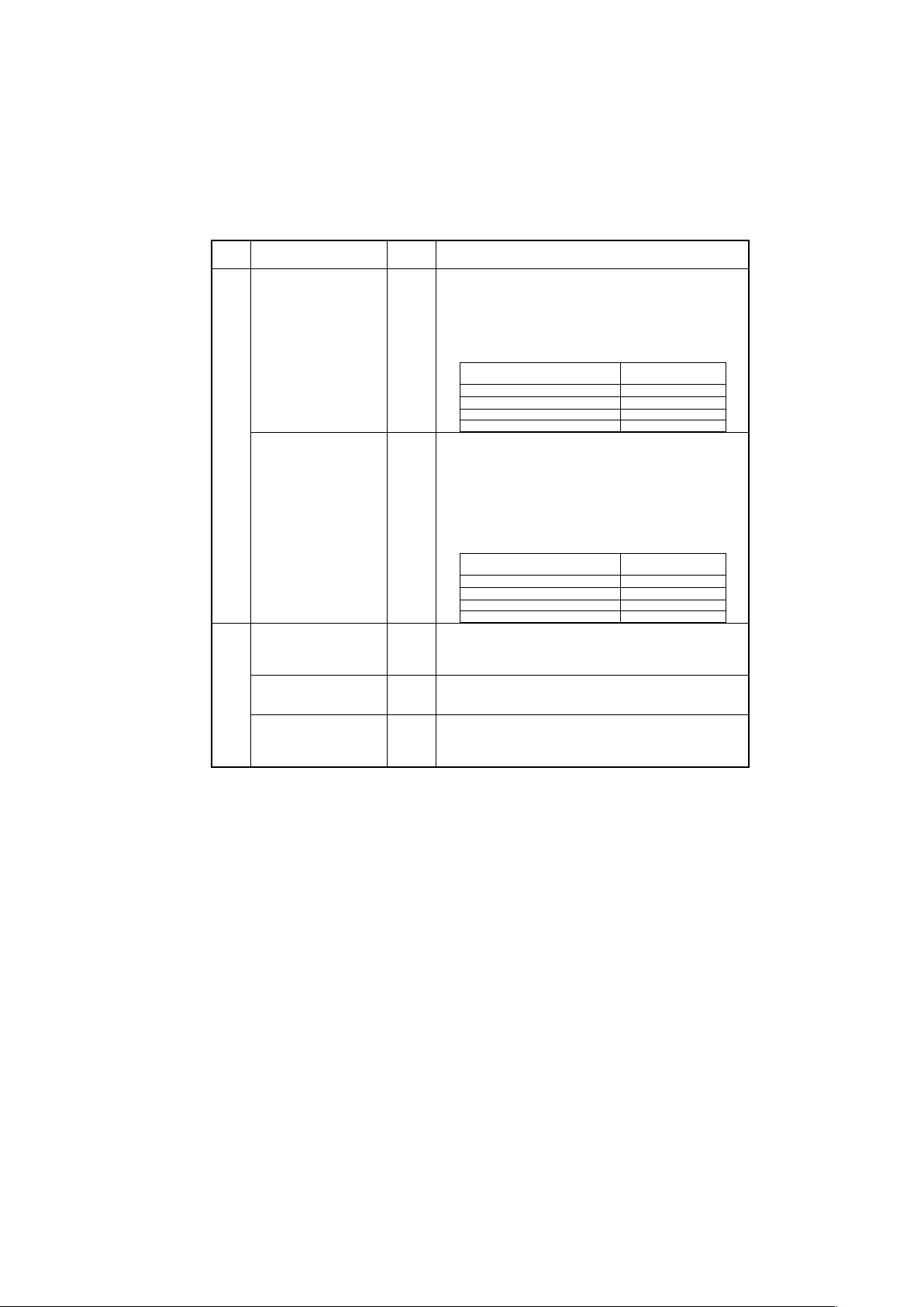
2.2.5 Terminal functions and wiring order
Main circuit terminals and grounding terminals
The table below shows the order of wiring and terminal functions. Carry out wiring in the order shown in Table
2.4 below.
Table 2.4 Order of Wiring and Functions of Main Circuit Terminals
Classifi-
cation
Name
Symbol
Functions
Main
circuit
(Note)
Primary grounding
terminals for inverter
enclosure
G
The two grounding terminals ( G) can be either used for
the power supply wiring (primary circuit) or motor wiring
(secondary circuit). Be sure to ground either of the two
grounding terminals for safety and noise reduction.
Secondary grounding
terminals for motor
G
Connect the secondary grounding wire for the motor to the
grounding terminal (
G).
Inverter output
terminals
U, V, W
Connect the three wires of the 3-phase motor to terminals
U, V, and W, taking care of the correct motor phase
correspondence. (*1)
Inverter output for Short
circuit
U0, V0, W0
For a short circuit for PMS motor.
These outputs are connected internally to U, V, W.
Auxiliary control power
input terminals *1
24V+, 24V-
Connect the power as for the 24VDC to these terminals as
a control circuit power backup.
R0, T0
Connect the same AC power as for the main circuit to these
terminals as a control circuit power backup.
DC reactor connection
terminals *2
P2, P3
Connect a DC reactor (DCR) to improve the power factor
and to fulfill with EN 12015 and EN 61000-3-12 regarding
harmonic distortion
When not connecting DCR, short-circuit by a wire.
P1,P(+)
Braking resistor
connection terminals
P(+), DB
Connect a braking resistor to use the regeneration brake.
DC link bus terminals
P(+), N(-)
A DC link bus is connectable to these terminals.
When you need to use the DC link bus terminals P(+) and
N(-), consult your Fuji Electric representative.
Main circuit power input
terminals
L1/R, L2/S,
L3/T
or L1/L, L2/N
The three-phase input power lines or single-phase input
power lines are connected to these terminals.
If the power wires are connected to other terminals, the
inverter will be damaged when the power is turned ON.
Control
circuit
Control circuit terminals
See Table
2.5.
Route the wiring of the control circuit as far from that of the
main circuit as possible. Otherwise, electric noise may
cause malfunctions.
When the Enable function is not to be used, short-circuit
terminals [EN1] and [PLC] and terminals [EN2] and [PLC]
using jumper wires.
(Note) Do not connect wiring to unassigned main circuit terminals (marked with NC). For details about the
terminal block, refer to Section 2.2.3 "Terminal arrangement diagrams and screw specifications."
*1) 24V+,24V-: 200 V class series inverters and 400 V ones of FRN0032 or less
R0T0 : 400 V ones of FRN0039 or above
*2) P2,P3 : 200 V class series inverters and 400 V ones of FRN0032 or less
P1,P(+) : 400 V ones of FRN0039 or above
Wiring of Auxiliary control power input terminals
Auxiliary control power input terminals 24V+ and 24V-
Terminal rating: 22 to 32VDC, Maximum current 2.0A, Maximum power 40W.
Auxiliary control power input terminals R0 and T0
Terminal rating: 220 to 480Vac 50Hz/60Hz, Maximum current 1.0A, Maximum power 50W.
! Wiring notes
To make the machinery or equipment compliant with the EMC standards, wire the motor and inverter in
accordance with the following.
(*1) Use shielded wires for the motor cable and route the cable as short as possible. Firmly clamp the shield to the
grounded metal plate.
#
For details about wiring, refer to Chapter 8, Section 8.4 "Compliance with EMC Standards."
Page 32

2-8
Control circuit terminals
Table 2.5 Names, Symbols and Functions of the Control Circuit Terminals
Classifi-
cation
Name
Symbol
Functions
Analog
input
Analog setting voltage input
[12]
External voltage input that commands the frequency externally.
(1) Input voltage range : 0 to ±10VDC / 0 to ±100%
(2) Hardware specifications
・Input impedance : 22 kΩ
・The maximum input voltage is ±15VDC, however, more than ±
15VDC is regarded as ±10VDC.
Analog setting voltage input
Analog setting current input
[V2]
(V2/C1)
External voltage input that commands the frequency externally.
(1) Input voltage range : 0 to ±10VDC / 0 to ±100%
(2) hardware specifications
・Input impedance : 22 kΩ
・The maximum input voltage is ±15VDC, however, more than ±
15VDC is regarded as ±10VDC.
External current input that commands the frequency externally.
(1) Input voltage range : 4 to 20mADC / 0 to 100%
(2) hardware specifications
・Input impedance : 250 Ω
・The maximum input current is 30mADC, however, more than
20mADC is regarded as 20mADC.
PTC/NTC thermistor input.
[NTC]
(PTC/NTC)
Connection of a PTC (Positive Temperature Coefficient) or NTC
(Negative Temperature Coefficient) thermistor for motor protection.
Analog common
[11]
Common terminal for analog input signals.
Digital
input
Digital input 1 to
Digital input 8
[X1]
[X2]
[X3]
[X4]
[X5]
[X6]
[X7]
[X8]
(1) Various signals such as "Coast to a stop," "Enable external
alarm trip," and "Select multi-frequency" can be assigned to
terminals [X1] to [X8], [FWD] and [REV] by setting function
codes E01 to E08, E98, and E99.
(2) Input mode, i.e. SINK and SOURCE, is changeable by using
the slide switch SW1.
(3) The logic value (1/0) for ON/OFF of the terminals [X1] to [X8],
[FWD], or [REV] can be switched. If the logic value for ON of
the terminal [X1] is "1" in the normal logic system, then OFF is
"1" in the negative logic system and vice versa.
(Digital input circuit specifications)
Run forward command
[FWD]
Run reverse command
[REV]
Item
Min.
Max.
Operating voltage
(SOURCE)
ON level
22 V
27 V
OFF level
0 V
2 V
Operating voltage
(SINK)
ON level
0V
2V
OFF level
22V
27V
Operating current at ON
(Input voltage is at 27 V)
2.5 mA
5 mA
Allowable leakage current at OFF
−
0.5 mA
[X1] to [X8],
[FWD],[REV]
Page 33

2-9
Table 2.5 Names, Symbols and Functions of the Control Circuit Terminals (continued)
Classifi-
cation
Name
Symbol
Functions
Digital
input
Enable input 1
Enable input 2
[EN1]
[EN2]
(1) Opening the circuit between terminals [EN1] and [PLC] or
terminals [EN2] and [PLC] stops the operation of the inverter
output transistorby STO functional safety function according to
IEC/EN 61800-5-2.
(2) The input mode of terminals [EN1] and [EN2] is fixed at the
SOURCE mode. No switching to the SINK mode is possible.
(3) If either one of [EN1] and [EN2] is OFF, an alarm occurs. (ECF
alarm)
This alarm state can be cleared only by turning the
inverter power off and on.
<Enable input circuit specifications>
[PLC]
[EN1]
5.4kΩ
5.4kΩ
[CM]
+24 VDC
Ph ot oco u ple r
<Control circuit>
[EN2]
PLC signal power
[PLC]
Connects to the output signal power supply of Programmable Logic
Controller (PLC).
Rated voltage: 24 VDC (Allowable range: +22 to +27 VDC),
Maximum output current 100 mA DC
Digital input common
[CM]
Common terminals for digital input signals
Item
Min.
Max.
Operating voltage
ON level
22 V
27 V
OFF level
0 V
2 V
Operating current at ON
(Input voltage is at 27 V)
2.5 mA
5 mA
Allowable leakage current at OFF
−
0.5 mA
Page 34

2-10
Table 2.5 Names, Symbols and Functions of the Control Circuit Terminals (continued)
Classifi-
cation
Name
Symbol
Functions
Analog
output
Analog monitor
[FMA]
These terminals output monitor signals for analog DC voltage (-10
to +10 V).
Analog common
[11]
Common terminal for analog output signals.
Transis-
tor
output
Transistor output 1 to
Transistor output 2
[Y1]
[Y2]
Both the SINK and SOURCE modes are supported.
(1) Various signals such as "Inverter running," "Frequency arrival
signal," and "Motor overload early warning" can be assigned to
terminals [Y1] and [Y2] by setting function code E20 and E21.
(2) The logic value (1/0) for ON/OFF of the terminals between
[Y1] or [Y2] and [CMY] can be switched. If the logic value for
ON between [Y1] or [Y2] and [CMY] is "1" in the normal logic
system,then OFF is "1" in the negative logic system and vice
versa.
(Transistor output circuit specification)
Photocoupler
<Control circuit>
[Y1]
[Y2]
[CMY]
61 to 67 V
Voltage
Current
Item
Max.
Operating voltage
ON level
3 V
OFF level
48 V
Maximum current at ON
50 mA
Leakage current at OFF
0.1 mA
Transistor output common
[CMY]
Common terminal for transistor output signals
Page 35
2-11
Table 2.5 Names, Symbols and Functions of the Control Circuit Terminals (continued)
Classifi-
cation
Name
Symbol
Functions
Relay
output
General-purpose relay
outputs
[Y3A/C]
[Y4A/C]
[Y5A/C]
(1) Any one of output signals that can be assigned to terminals [Y1]
and [Y2] can also be assigned to this relay contacts, as a
general-purpose relay output, in order to use it for outputting a
signal.
(2) Whether excitation or non-excitation causes this terminal to
output a signal can be switched.
(3) Contact capacity and the life are shown by table below.
Contact capacity
Average of life
(cycle)
250VAC,0.5A,cosΦ=0.3
300,000
250VAC,1A,cosΦ=0.3
150,000
30VDC,0.5A
300,000
30VDC,1A
150,000
Alarm relay output
(for any error)
[30A/B/C]
(1) When the protective function is activated, this terminal outputs
a contact signal (1C) to stop the motor.
(2) Any one of output signals that can be assigned to terminals [Y1]
and [Y2] can also be assigned to this relay contact as a
general-purpose relay output, in order to use it for outputting a
signal.
(3) Whether excitation or non-excitation causes this terminal to
output a signal can be switched.
(4) Contact capacity and the life are shown by table below.
Contact capacity
Average of life
(cycle)
250VAC,0.5A,cosΦ=0.3
100,000
250VAC,1A,cosΦ=0.3
50,000
30VDC,0.5A
100,000
30VDC,1A
50,000
Com-
munica-
tion
RS-485 communications
port 2
(On the terminal block)
[DX+]/
[DX-]
These I/O terminals are used as a communications port that
transmits data through the RS-485 multipoint protocol between the
inverter and a computer or other equipment such as a PLC or
elevator controller.
RS-485 communications
port 1 (For connection of the
keypad)
RJ-45
connector
Used to connect the keypad to the inverter. The inverter supplies
the power to the keypad via the extension cable for remote
operation.
CAN open communications
[CAN+]
[CAN-]
[CANG]
These I/O terminals are used as a communications port that
transmits data through the CANopen multipoint protocol between
the inverter and a computer or other equipment such as a PLC or
elevator controller.
Page 36

2-12
2.2.6 Connection diagrams
This section shows connection diagrams with the Enable input function used.
FRN0011LM2A-7□/ FRN0018LM2A-7□, FRN0006LM2A-4□to FRN0032LM2A-4□
R
S
Motor
(FWD)
(REV)
(X1)
(X2)
(X3)
(X4)
(X5)
(X6)
(X7)
(X8)
(CM)
(12)
(11)
(C1)
U
V
W
M
<Y2>
<Y1>
<CMY>
(CM)
Ground
+DC24V
0V
Voltage input
for setting
-10V to 0 to +10V
DC REACTOR
DCR (*3)
T
(PLC)
(CAN-)(CAN+)
Digital input
Auxiliary control
power input (*2)
P3
P(+) DB
EXTERNAL BRAKING
RESISTOR
G
P
1
2
DB
Relay output
G
Alarm output
(for any fault)
<30A>
<30B>
<30C>
<Y4C>
<Y4A>
Ground
(PLC) or (CM) (*7)
(THR)
Three-phase
Power supply(*4)
MCCB or
RCD/ELCB (*1)
(-)
(+)
(PO)
(PA)
(PB)
N(-)
(-)
(+)
RS485 Port1
Keypad communication
RS485 (also Modbus RTU,
DCP3, DCP4, PC Loader)
RJ45
(*5)
(*11)
(*11)
(PZ)
(CM)
PG
SINK
SOURCE
<PAO+>
Voltage input or
Current input
for setting
-10V to 0 to +10V
4mA to 20mA
Analog input
(11)
+DC15V
+DC12V
(*9)
CAN port
Refer to
1.Standard specfications
L1/L
L2/N
Single-phase
Power supply
Refer to
1.Standard specfications
<Y5A>
<Y5C>
Fuse
(*6)
EMC Filter
Transistor output
(EN1)
(EN2)
(CM)
Option card
(*10)
Safety module
Compliant to
EN ISO13849-1 (*8)
RCD: Residual-current-operated
protective device
ELCB: Earth Leakage Circuit Breaker
MCCB: Molded Case Circuit Breaker
(PLC)
(CANG)
24VDC
Input
<FMA>
<11>
Analog output
P2
(DX+)(DX-)
RS485 port2
(*12)
<PAO->
<PBO+>
<PBO->
24V-
24V+
RS485 port1
<Y3C>
<Y3A>
(PLC)
SW1
(CM)
(CM)
(V2)
SW4
(NTC)
0V
+DC10V
(-)
(+)
PTC/NTC
thermistor
or
UVW
Terminals for short circuit
(*13)
U0
V0
W0
External Contactor
(Normally closed)
(SCC)
(SCCF)
EMC ON/OFF switch (*14)
(V2)
Page 37

2-13
(*1) Install a recommended molded case circuit breaker (MCCB) or residual-current-operated protective device
(RCD)/earth leakage circuit breaker (ELCB) (with over current protection function) in the primary circuit of
the inverter to protect wiring.
(*2) Refer to table 2.4.
(*3) Mount a jumper cable between terminals P2 and P3 when a DCR is not used. The direct current reactor
(DCR) is a separately installed option.
(*4) Use the inverter connecting the power system which has earthed neutral-point. In case of non-earthed
system (ex. I-T NET), the control interface of the inverter becomes basic insulation, thus do not connect
SELV circuit from external controller directly.
(*5) For the control signal wires, use shielded or twisted wires. Ground shielded wires. To prevent malfunction
due to noise, keep the control circuit wiring away from the main circuit wiring as far as possible
(recommended: 10cm or more), and never lay them in the same wire duct. When crossing the control circuit
wiring with the main circuit wiring, lay them at right angles.
(*6)
To bring the inverter into compliance with the European electrical safety standard IEC/EN 61800-5-1 or compliance
with Canadian and U.S. standards (CSA certification), be sure to insert the specified fuse (see Instruction Manual)
in the primary circuit of the inverter.
(*7) Connection terminal depends on SOURCE/SINK setting by slide switch SW1 (please refer to chapter
2.2.7). Connect to (PLC) terminal when SOURCE is set, and to (CM) terminal when SINK is set.
(*8) When the Enable inputs (EN1, EN2) function is not to be used, keep terminals [EN1]-[PLC] and [EN2]-[PLC]
short circuited using jumper wires. For opening and closing the hardware circuit between terminals [EN1]
and [PLC] and between [EN2] and [PLC], use safe relay device approved according to EN ISO 13849-1
PL-e, IEC/EN 61800-5-2 SIL3 or EN81-1 and EN 81-20.
(*9) Wiring must use shielded lines. Please connect the shield appropriately according to the specification of
the encoder and the connection with the controller. In the above figure, the shield is connected with the
earth line of the inverter side and not connected on the motor. It is likely to be improved by connecting the
inverter side with (CM) when malfunction occurs due to noise etc. When the wiring between the encoder
and the inverter is long, the allophone and the torque ripple might be generated because the signal from the
encoder malfunctions by interfering with A phase and B phase. In this case, please execute measures such
as; wiring shorter cable, cable of smaller stray capacitance, etc.
(*10) The encoder interface is provided by an option card.
(*11) and are separated and insulated.
(*12) CAN signals are isolated from other internal circuit.
(*13) U0,V0,W0 are connected with U,V,W respectively.
(*14) The EMC filter can be enabled/disabled. If the EMC terminal is connected, EMC filter is enabled (this is
default setting). If the EMC terminal is disconnected, the EMC filter is disabled.
0V
0V
Page 38

2-14
FRN0039LM2A-4□to FRN0091LM2A-4□
Motor
M
G
Ground
DC REACTOR
DCR (*3)
R0
T0
Auxiliary control
power input (*2)
EXTERNAL BRAKING
RESISTOR
G
G
Ground
(PLC) or (CM) (*7)
(THR)
Three-phase
Power supply (*4)
MCCB or
RCD/ELCB (*1)
Refer to
1.Standard specfications
Refer to
1.Standard specfications
Fuse
(*6)
Cy-on
Cy-off
L1/R
L2/S
U
V
W
L3/T
P1
P(+) DB
G
P
1
2
DB
N(-)
EMC Filter
RCD: Residual-current-operated
protective device
ELCB: Earth Leakage Circuit Breaker
MCCB: Molded Case Circuit Breaker
(FWD)
(REV)
(X1)
(X2)
(X3)
(X4)
(X5)
(X6)
(X7)
(X8)
(CM)
(12)
(11)
(C1)
<Y2>
<Y1>
<CMY>
(CM)
+DC24V
0V
Voltage input
for setting
-10V to 0 to +10V
(PLC)
Digital input
Relay output
Alarm output
(for any fault)
<30A>
<30B>
<30C>
<Y4C>
<Y4A>
(-)
(+)
(-)
(+)
RS485 Port1
Keypad communication
RS485 (also Modbus RTU,
DCP3, DCP4, PC Loader)
RJ45
(*5)
(*11)
(*11)
SINK
SOURCE
Voltage input or
Current input
for setting
-10V to 0 to +10V
4mA to 20mA
Analog input
(11)
<Y5A>
<Y5C>
Transistor output
(EN1)
(EN2)
Safety module
Compliant to
EN ISO13849-1 (*8)
(PLC)
<AO1>
<M>
Analog output
(DX+)(DX-)
RS485 port2
RS485 port1
<Y3C>
<Y3A>
(PLC)
SW1
(CM)
(CM)
(V2)
SW4
(PTC/NTC)
0V
+DC10V
(-)
(+)
PTC/NTC
thermistor
or
External Contactor
(Normally closed)
(SCC)
(SCCF)
U
V
W
(CAN-)(CAN+)
(*9)
CAN port
Option card
(*10)
(CANGND)
PG
(*12)
0V
Page 39

2-15
(*1) Install a recommended molded case circuit breaker (MCCB) or residual-current-operated protective device
(RCD)/earth leakage circuit breaker (ELCB) (with over current protection function) in the primary circuit of the
inverter to protect wiring.
(*2) Even if this terminal is not connected, the inverter can be operated with connection of the main circuit (L1/R, L2/S,
L3/T).
Please wire for this terminal to operate the control circuit of the inverter when there is no power supply.
(*3) When connecting an optional DC reactor (DCR), remove the jumper bar from the terminals P1 and P(+). The direct
current reactor (DCR) is a separately installed option.
(*4) Use the inverter connecting the power system which has earthed neutral-point. In case of non-earthed system (ex.
I-T NET), the control interface of the inverter becomes basic insulation, thus do not connect SELV circuit from
external controller directly.
(*5) For the control signal wires, use shielded or twisted wires. Ground shielded wires. To prevent malfunction due to
noise, keep the control circuit wiring away from the main circuit wiring as far as possible (recommended: 10cm or
more), and never lay them in the same wire duct. When crossing the control circuit wiring with the main circuit wiring,
lay them at right angles.
(*6) To bring the inverter into compliance with the European electrical safety standard IEC/EN 61800-5-1 or compliance
with Canadian and U.S. standards (CSA certification), be sure to insert the specified fuse (see Instruction Manual) in
the primary circuit of the inverter.
(*7) Connection terminal depends on SOURCE/SINK setting by slide switch SW1. Connect to (PLC) terminal when
SOURCE is set, and to (CM) terminal when SINK is set.
(*8) When the Enable inputs (EN1, EN2) function is not to be used, keep terminals [EN1]-[PLC] and [EN2]-[PLC] short
circuited using jumper wires. For opening and closing the hardware circuit between terminals [EN1] and [PLC] and
between [EN2] and [PLC], use safe relay device approved according to EN ISO 13849-1 PL-e, IEC/EN 61800-5-2
SIL3 or EN81-1 and EN 81-20.
(*9) Wiring must use shielded lines. Please connect the shield appropriately according to the specification of the encoder
and the connection with the controller. In the above figure, the shield is connected with the earth line of the inverter
side and not connected on the motor. It is likely to be improved by connecting the inverter side with (CM) when
malfunction occurs due to noise etc. When the wiring between the encoder and the inverter is long, the allophone
and the torque ripple might be generated because the signal from the encoder malfunctions by interfering with A
phase and B phase. In this case, please execute measures such as; wiring shorter cable, cable of smaller stray
capacitance, etc.
(*10) The encoder interface is provided by an option card.
(*11) and are separated and insulated.
(*12) CAN signals are isolated from other internal circuit.
0V
0V
Page 40

2-16
2.2.7 Setting the slide switches on the control PCB
Switching the slide switches located on the control PCB (see Figure 2.4) allows you to customize the operation
mode of the analog output terminals, digital I/O terminals, and communications ports.
To access the slide switches, remove the front cover so that you can see the control PCB.
#
For details on how to remove the front cover, refer to Section 2.2.1.
Table 2.6 lists function of each slide switch.
Table 2.6 Function of Slide Switches
Switch
Function
SW1
Switches the service mode of the digital input terminals between SINK and SOURCE.
SW2
Switches the terminating resistor of RS-485 communications port 1 on the inverter ON and OFF.
(RS-485 communications port 1 for connecting the keypad)
SW3
Switches the terminating resistor of RS-485 communications port 2 on the inverter ON and OFF.
(RS-485 communications. port 2 on the terminal block)
SW4
Switches the function of terminal [V2/C1] between V2 and C1.
SW5
Switches the terminating resistor of CANopen communications port on the inverter ON and OFF
(CANopen communications port on the terminal block).
Figure 2.4 shows the location of slide switches on the control PCB.
Slide switches configuration and factory default
• Before changing the switches, confirm the power supply tuned OFF.
An electric shock may result if this warning is not heeded as
there may be some residual electric charge in the DC bus
capacitor even after the power has been turned OFF.
SW1
SW2
SW3
SW4
SW5
Figure 2.4 Location of the Slide Switches on the Control PCB
To change the setting of a slide switch, use a tool with a narrow tip (e.g., a tip of tweezers). Be
careful not to touch other electronic parts, etc. If the slide switch is in an intermediate position, it is
unclear whether the circuit is turned ON or OFF, and the digital input remains in an undefined state.
Be sure to place the slide switch so that it contacts either side of the switch.
Slide switch in the correct position
or
Slide switch in an ambiguous
position
2.2.8 Mounting and connecting the keypad to the panel
You can remove the keypad cover from the inverter unit and to mount keypad (option) on the panel or install it
ata remote site. (e.g., for operation on hand).
#
For detailed instructions on how to mount the keypad on the panel, refer to the TP-A1-LM2 installation
manual.
Page 41

3-1
Chapter 3 OPERATION USING THE KEYPAD
The FRENIC-Lift has no standard keypad. Using the optional multi-function keypad allows you to start and stop
the motor, monitor running status, and switch to the menu mode. You may also set the function code data,
monitor I/O signal states, maintenance information, and alarm information.
For details of the multi-function keypad, refer to the FRENIC-Lift LM2A series Reference Manual.
Page 42

4-1
Chapter 4 RUNNING THE MOTOR FOR A TEST
4.1 Checking Prior to Powering ON
Check the following before powering on the inverter.
(1) Check that the wiring is correct.
Especially check the wiring to the inverter input terminals L1/R, L2/S and L3/T and output terminals U, V, and
W. Also check that the grounding wires are connected to the grounding terminals (
G) correctly. See Figure
4.1.
(2) Check the control circuit terminals and main circuit terminals for short circuits or ground faults.
(3) Check for loose terminals, connectors and screws.
(4) Check that the motor is separated from mechanical equipment.
(5) Make sure that all switches of devices connected to the inverter are turned OFF. Powering on the inverter
with any of those switches being ON may cause an unexpected motor operation.
(6) Check that safety measures are taken against runaway of the equipment, e.g., a defense to prevent people
from access to the equipment.
Inverter
L1/R L2/S L3/T U V W
GG
Power
Motor
supply
Figure 4.1 Connection of Main Circuit Terminals
4.2 Powering ON and Checking
Turn the power ON and check the following points. The following assumes that no function code data is changed
from the factory default.
(1) Check that the charge lamp lights up.
Page 43

4-2
4.3 Configuring the Function Code Data Before Test Run
Configure the function codes listed below according to the motor ratings and your machinery design values. For
the motor ratings, check the ratings printed on the motor's nameplate. For your machinery design values, ask
system designers about them.
!
To set up function code, you need to use the keypad (option) or to access their data via communications
link. For details, refer to the FRENIC-Lift LM2A series Reference Manual.
Table 4.1 Configuring Function Code Data
Function
code
Name
Function code data
Factory defaults
F04
Base Speed
Motor ratings
(printed on the nameplate
of the motor)
1500 (r/min)
F05
Rated Voltage at Base
Speed
190 (V) / 380 (V)
P01*
Motor (No. of poles)
4 (P)
P02
Motor (Rated capacity)
Nominal applied motor capacity.
P03
Motor (Rated current)
Rated current of nominal applied motor.
P06
Motor (No-load current)
No load current of the standard motor.
P07
Motor (%R1)
Primary resistance of the standard motor.
P08
Motor (%X)
Leakage reactance of the standard motor.
P12
Motor (Rated slip)
0.00 (Hz)*1
*1 The rated slip of the standard motor is
applied.
L01
Pulse Encoder (Selection)
Depending on data sheet
of the pulse encoder.
0 : 12V/15V complementary, open collector
output circuit or 5V line driver.
L02
Pulse Encoder (Resolution)
1024 (pulse / rev)
L04
Magnetic pole position
Offset (Offset angle)
0.00 (deg)
F03*
Rated Speed
Machinery design values.
1450 (r/min)
F42
Motor Control Mode
Selection 1
0 : Vector control with PG
(Asynchronous motor)
C21*
Speed Command Unit
0 : r/min (Speed data format)
L31*
Elevator Parameter (Speed)
1000 (mm/s)
H190
Motor rotate direction
1 : Motor rotates in CW(Clockwise) direction
*
Recommend to start the setting by the following order C21, P01, F03 and L31, etc.
・In any of the following cases, motor auto-tuning (P04) is necessary because the standard settings of
motor parameters for Fuji motors are not applicable:
- The motor to be driven is not a Fuji product or is a non-standard product.
- The cabling between the motor and the inverter is long.
- A reactor is inserted between the motor and inverter.
・To drive a synchronous motor, you need to tune the inverter for the offset angle of magnet pole before
running the motor. (L03)
・To drive a motor with encoder, an option card should be used which has to be ordered separately.
!
For details of motor tuning procedure refer to the FRENIC-Lift LM2A series Reference Manual.
Page 44

4-3
4.4 Running the Inverter for Motor Operation Check
After preparations of 4.1-4.3 have been completed, begin to perform the test drive of the motor.
Turn on both terminals [EN1] and [EN2] before running the motor.
If terminals [EN1] or [EN2] and [PLC] are not connected, the motor doesn’t rotate.
------------------------------- Test Run Procedure using the multi-function keypad (option)
------------------------------
(1) Turn the power ON and check that the LCD monitor blink while indicating a reference speed of 0.00.
(2) Enter the local mode by holding down the
key for at least 2 seconds. Pressing this key toggles between
Local mode and Remote mode.
(3) Select a low reference speed (safety speed) by using the / Key. Be sure of that the reference speed
blinks on the LCD monitor.
(4) Press the
key to start running the motor in the forward direction. Check that the reference speed is
displayed on the LCD monitor correctly. Also check whether the motor rotating direction is correct.
(5) To stop the motor, press the key.
(6) Press the
key to start running the motor in the reverse direction. Check that the reference speed is
displayed on the LCD monitor correctly. Also check whether the motor rotating direction is correct.
(7) To stop the motor, press the
key.
When turning the power OFF and ON again, the inverter returns to Remote mode.
< Check the following points >
・Pressing the
key runs the motor forward.
・Pressing the
key runs the motor reverse.
・Check for smooth rotation without motor humming or excessive vibration.
・Check for smooth acceleration and deceleration.
When no abnormality is found, press the
or
key again to start driving the motor and increase the motor
speed using
/
keys. Check the above points again.
---------------------------------------------------------------------------------------------------------------------------------------------------
4.5 Preparation for Practical Operation
After confirming correct operation by performing a test run, make mechanical connections (connections of the
machine system) and electrical connections (wiring and cabling), and set the necessary parameters properly
before starting normal machine operation .
Before to proceed running the inverter in normal operation check the related function code data again
and reconfigure it if needed.
Page 45

5-1
Chapter 5 TROUBLESHOOTING
5.1 Alarm Codes
Table 5.1 Quick List of Alarm Codes
Code
Name
Description
OC1
OC2
OC3
Instantaneous overcurrent
The inverter momentary output current exceeded the
overcurrent level.
OC1: Overcurrent during acceleration
OC2: Overcurrent during deceleration
OC3: Overcurrent during running at a constant speed
EF
Ground fault
Zero-phase current caused by ground fault in the output
circuit has exceeded the allowable limit.
(30kW or above)
OV1
OV2
OV3
Overvoltage
The DC link bus voltage exceeded the overvoltage
detection level.
OV1: Overvoltage during acceleration
OV2: Overvoltage during deceleration
OV3: Overvoltage during running at a constant speed
LV
Undervoltage
The DC link bus voltage dropped below the undervoltage
detection level.
Lin*
Input phase loss
An input phase loss occurred or the Interphase voltage
unbalance rate was large.
OPL*
Output phase loss
An output phase loss occurred.
OH1
Heat sink overheat
The temperature around the heat sink has risen
abnormally.
OH2
External alarm
The external alarm THR was entered.
(when the THR "Enable external alarm trip" has been
assigned to any digital input terminal)
OH3
Inverter internal overheat
The temperature inside the inverter has exceeded the
allowable limit.
OH4
Motor protection (PTC/NTC thermistor)
The temperature of the motor has risen abnormally.
OH6
Charging resistor overheat
The temperature of the charging resistor inside the
inverter has exceeded the allowable limit.
DBH
Braking register overheat
The temperature of the Braking resistor has exceeded
the allowable limit.
OL1
Overload of motor 1
The electronic thermal protection for motor overload
detection was activated.
OLU
Inverter overload
The temperature inside the IGBT has risen abnormally.
DBA*
Braking transistor broken
Detection of an abnormality in the brake transistor
Er1
Memory error
An error has occurred when writing data to the inverter
memory.
Er2
Keypad communications error
A communications error has occurred between the
keypad and the inverter.
Er3
CPU error
A CPU error or LSI error has occurred.
Er4
Option communications error
A communications error has occurred between the
connected option card and the inverter.
Er5
Option error
An error was detected by the connected option card (not
by the inverter).
Er6
Operation protection
An incorrect operation was attempted.
Er7
Tuning error
Auto-tuning or Magnetic Pole Position Offset tuning has
failed, resulting in abnormal tuning results.
Er8
ErP
RS-485 communications error
(Er8: RS-485 port 1, ErP: port 2)
A communications error has occurred during RS-485
communication.
ErF
Data saving error during undervoltage
When the undervoltage protection was activated, the
inverter failed to save data, showing this error.
ErH
Hardware error
The LSI on the power printed circuit board has
malfunctioned due to noise, etc.
Page 46

5-2
Table 5.1 Quick List of Alarm Codes(Continued)
Code
Name
Description
PG
Broken wiring in the PG
The inverter detects a broken wiring connection in the
pulse encoder.
Ert
CANopen communication error
A communications error has occurred during CANopen
communication.
OS
Over speed prevention
The motor speed is higher than maximum speed * L32.
ErE
Speed mismatching
The reference speed and the detection speed are
different.
Ot
Over torque current
Reference torque current became excessive.
bbE
Brake confirmation
The inverter detects mismatch between the brake control
signal and brake detection (feedback) signal.
tCA
Reaching maximum numbers of trip counter
The number of trip direction changes has reached the
preset level.
SCA
Short-circuit control error
The inverter detects mismatch between the short-circuit
control signal and short-circuit detection (feedback)
signal.
LCO
Load-cell overload
Load-cell function has detected overload situation by
means of preset level.
rbA
Rescue by brake alarm
No movement detected during rescue operation by brake
control.
nrb
NTC wire break error
Detected a wire break in the NTC thermistor detection
circuit.
ECL
Customizable logic error
A customizable logic configuration error has caused an
alarm.
Eo
EN1, EN2 terminals chattering
Detected collision between ENOFF output and EN1/EN2
input terminals.
ECF
EN1, EN2 terminals circuit error
An abnormality was diagnosed in EN1, EN2 terminals
circuit.
* These alarms can change enable/disable by a function code.
!
For detail of function code refer to the FRENIC-Lift LM2A series Reference Manual.
Page 47

6-1
Chapter 6 MAINTENANCE AND INSPECTION
Perform daily and periodic inspections to avoid trouble and keep reliable operation of the inverter for a long time.
6.1 Daily Inspection
Visually inspect the inverter for operation errors from the outside without removing the covers when the inverter
is ON or operating.
- Check that the expected performance (satisfying the standard specifications) is obtained.
- Check that the surrounding environment satisfies the environmental requirements given in Chapter 7, Section
7.1 "Standard Model."
- Check that the keypad displays normally.
- Check for abnormal noise, odor, or excessive vibration.
- Check for traces of overheat, discoloration and other defects.
6.2 Periodic Inspection
Before starting periodic inspections, be sure to stop the motor, shut down the power, and wait at least 10 minutes.
Make sure that the charging lamp is turned OFF. Further, make sure, using a multimeter or a similar instrument,
that the DC link bus voltage between the main circuit terminals P(+) and N(-) has dropped to the safe level (+25
VDC or below).
Table 6.1 List of Periodic Inspections
Check part
Check item
How to inspect
Evaluation criteria
Environment
1) Check the ambient temperature,
humidity, vibration and atmosphere
(dust, gas, oil mist, or water drops).
2) Check that tools or other foreign
materials or dangerous objects are
not left around the equipment.
1) Check visually or
measure using
apparatus.
2) Visual inspection
1) The standard
specifications must be
satisfied.
2) No foreign or dangerous
objects are left.
Input voltage
Check that the input voltages of the
main and control circuit are correct.
Measure the input
voltages using a
multimeter or the like.
The standard specifications
must be satisfied.
Keypad
1) Check that the display is clear.
2) Check that there is no missing part
in the displayed characters.
1), 2)
Visual inspection
1), 2)
The display can be read
and there is no fault.
Structure such
as frame and
cover
Check for:
1) Abnormal noise or excessive
vibration
2) Loose bolts (at clamp sections).
3) Deformation and breakage
4) Discoloration caused by overheat
5) Contamination and accumulation of
dust or dirt
1) Visual or auditory
inspection
2) Retighten.
3), 4), 5)
Visual inspection
1), 2), 3), 4), 5)
No abnormalities
Main circuit
Common
1) Check that bolts and screws are
tight and not missing.
2) Check the devices and insulators
for deformation, cracks, breakage
and discoloration caused by
overheat or deterioration.
3) Check for contamination or
accumulation of dust or dirt.
1) Retighten.
2), 3)
Visual inspection
1), 2), 3)
No abnormalities
Conductors
and wires
1) Check conductors for
discoloration and distortion
caused by overheat.
2) Check the sheath of the wires for
cracks and discoloration.
1), 2)
Visual inspection
1), 2)
No abnormalities
Page 48

6-2
Terminal
blocks
Check that the terminal blocks are
not damaged.
Visual inspection
No abnormalities
Page 49

6-3
Table 6.1 List of Periodic Inspections (Continued)
Check part
Check item
How to inspect
Evaluation criteria
Main circuit
DC link bus
capacitor
1) Check for electrolyte leakage,
discoloration, cracks and swelling
of the casing.
2) Check that the safety valve is not
protruding remarkably.
3) Measure the capacitance if
necessary.
1), 2)
Visual inspection
3) Measure the discharge
time with capacitance
probe.
1), 2)
No abnormalities
3) The discharge time
should not be shorter
than the one specified by
the replacement manual.
Transformer
and reactor
Check for abnormal roaring noise
and odor.
Auditory, visual, and
olfactory inspection
No abnormalities
Magnetic
contactor
and relay
1) Check for chatters during
operation.
2) Check that contact surface is not
rough.
1) Auditory inspection
2) Visual inspection
1), 2)
No abnormalities
Control circuit
Printed
circuit board
1) Check for loose screws and
connectors.
2) Check for odor and discoloration.
3) Check for cracks, breakage,
deformation and rust.
4) Check the capacitors for
electrolyte leaks and deformation.
1) Retighten.
2) Olfactory and visual
inspection
3), 4)
Visual inspection
1), 2), 3), 4)
No abnormalities
Cooling system
Cooling fan
1) Check for abnormal noise and
excessive vibration.
2) Check for loose bolts.
3) Check for discoloration caused by
overheat.
1) Auditory and visual
inspection, or turn
manually (be sure to
turn the power OFF).
2) Retighten.
3) Visual inspection
1) Smooth rotation
2), 3)
No abnormalities
Ventilation
path
Check the heat sink, intake and
exhaust ports for clogging and
foreign materials.
Visual inspection
No abnormalities
Remove dust accumulating on the inverter with a vacuum cleaner. If the inverter is stained, wipe it off with a
chemically neutral cloth.
6.3 List of Periodic Replacement Parts
The inverter consists of many electronic parts including semiconductor devices. Table 6.2 lists replacement parts
that should be periodically replaced for preventive maintenance (use the lifetime judgment function as a guide).
These parts are likely to deteriorate with age due to their construction and properties, leading to the decreased
performance or failure of the inverter.
When the replacement is necessary, consult your Fuji Electric representative.
Table 6.2 Replacement Parts
Part name
Standard replacement intervals
(See Notes below.)
400V/200V class series
DC link bus capacitor
7 years
Electrolytic capacitors on printed circuit
boards
7 years
Cooling fans
7 years
Relay output of control circuit terminals
Refer to Table 2.5.
Page 50

6-4
(Notes) ! These replacement intervals are based on the inverter's service life estimated at an ambient temperature of 40
°C, and with a load factor of 80%. Replacement intervals may be shorter when the ambient temperature
exceeds 40 °C, or when the inverter is used in an excessively dusty environment.
! Standard replacement intervals mentioned above are only a guide for replacement, and not a guaranteed
service life.
6.4 Inquiries about Product and Guarantee
6.4.1 When making an inquiry
Upon breakage of the product, uncertainties, failure or inquiries, inform your Fuji Electric representative of the
following information.
1) Inverter type (Refer to Chapter 1, Section 1.1.)
2) SER No. (serial number of the product) (Refer to Chapter 1, Section 1.1.)
3) Function codes and their data that you changed (Refer to the FRENIC-Lift LM2A series Reference Manual)
4) ROM version (Refer to FRENIC-Lift LM2A series Reference Manual)
5) Date of purchase
6) Inquiries (for example, point and extent of breakage, uncertainties, failure phenomena and other
circumstances)
Page 51

7-1
Chapter 7 SPECIFICATIONS
7.1 Standard Model
1) Three-phase 400V series
Item
Specifications
Type FRN___LM2A-4□
0006
0010
0015
0019
0025
0032
Nominal applied motor [kW]
2.2
4.0
5.5
7.5
11
15
Output ratings
Rated capacity *1 [kVA]
4.6
7.6
11
14
18
24
Rated voltage *2 [V]
Three-phase 380V-480V, 50/60Hz
Rated current *3 [A]
6.1
10.0
15.0
18.5
24.5
32.0
Overload capacity [A]
(Permissible overload time)
11.0
(3s)
18.0
(3s)
27.0
(3s)
37.0
(3s)
49.0
(3s)
64.0
(3s)
Rated frequency [Hz]
50, 60Hz
Input ratings
Main power supply
Normal operation
Phases, Voltage, Frequency
Three-phase, 380 to 480V, 50/60Hz
Variations
Voltage: +10 to -15% (Voltage unbalance: 2% or less *4)
Frequency: +5 to -5%
Rated
current
*5
[A]
with DCR
4.5
7.5
10.6
14.4
21.1
28.8
Without DCR
8.2
13
17.3
23.2
33.0
43.8
Required power supply capacity
(with DCR) [kVA]
3.2
5.2
7.4
10
15
20
UPS
operation
Phases,Voltage,Frequency
Single-phase, 220 to 480V, 50/60Hz
Variations
Voltage: +10 to -10% ,Frequency: +5 to -5%
Operation time [s]
180
Battery
operation
Power Supply Voltage for driving
DC 48V or more in the direct current voltage conversion.
Operation time [s]
180
Auxiliary control power supply Voltage
DC 24V (22V to 32V) ,Maximum 40W
Braking
Braking time*7 [s]
60
Braking duty-cycle (%ED)
*7
[%]
50
Rated regenerative power*7 [kW]
1.8
3.2
4.4
6.0
8.8
12
Minimum resistance which can be
connected [Ω]
*6
160
96
47
47
24
24
EMC filter
Built-in (According to EN12015, EN12016)
Enclosure (IEC60529)
IP20 Heat sink
IP54
Cooling method
Fan cooling
Average sound pressure level
at trip.[dBA]
*8
44.5
48
49.5
Average power losses [W]
in standstill
*12
23
26
in standby
*13
16
Weight/Mass [kg]
4.4
4.4
4.7
4.7
6.1
6.3
Page 52

7-2
Item
Specifications
Type FRN___LM2A-4□
0039
0045
0060
0075
0091
Nominal applied motor [kW]
18.5
22
30
37
45
Output ratings
Rated capacity *1 [kVA]
29
34
45
57
69
Rated voltage *2 [V]
Three-phase 380V-480V, 50/60Hz
Rated current *3 [A]
39.0
45.0
60.0
75.0
91.0
Overload capacity [A]
(Permissible overload time)
78.0
(3s)
90.0
(3s)
120
(3s)
150
(3s)
182
(3s)
Rated frequency [Hz]
50, 60Hz
Input ratings
Main power supply
Normal operation
Phases, Voltage, Frequency
Three-phase, 380 to 480V, 50/60Hz
Variations
Voltage: +10 to -15% (Voltage unbalance: 2% or less *4)
Frequency: +5 to -5%
Rated
current
*5
[A]
with DCR
35.5
42.2
57.0
68.5
83.2
Without DCR
52.3
60.6
77.9
94.3
114
Required power supply capacity
(with DCR) [kVA]
25
30
40
48
58
UPS
operation
Phases,Voltage,Frequency
Single-phase, 220 to 480V, 50/60Hz
Variations
Voltage: +10 to -10% ,Frequency: +5 to -5%
Operation time [s]
180
Battery
operation
Power Supply Voltage for driving
DC 48V or more in the direct current voltage conversion
Operation time [s]
180
Auxiliary control power supply Voltage
Single-phase
220 to 480V, 50/60Hz
*9
Braking
Braking time*7 [s]
60
Braking duty-cycle (%ED)
*7
[%]
50
Rated regenerative power*7 [kW]
14.8
17.6
24
29.6
36
Minimum resistance which can be
connected [Ω]
*6
16
16
10
8.5
8
EMC filter
Built-in (According to EN12015, EN12016)
Enclosure (IEC60529)
IP20
IP00 Heat sink
IP20
IP00
Cooling method
Fan cooling
Average sound pressure level at trip.[dBA]
*8
55
60
Average power losses [W]
in standstill
*12
26
33
in standby
*13
16
18
Weight/Mass [kg]
10.5
11.2
27
28
32
*1) Rated capacity is calculated by regarding the output rated voltage as 440V .
*2) Output voltage cannot exceed the power supply voltage.
*3) These values correspond to the following conditions: carrier frequency is 10 kHz (2 phase modulation) and ambient
temperature is 45°C.
Select the inverter capacity such that the square average current during operation is not higher than the 80% of the
rated current of the inverter.
*4) Voltage unbalance [%] =
(Max.voltage [V] - Min.voltage [V])/ Three-phase average voltage [V] x 67 (IEC61800-3)
*5) The power supply capacity is 500kVA (ten times the inverter capacity when the inverter capacity exceeds 50kVA), and
the value of the power supply impedance is %X=5%.
*6) The admissible error of minimum resistance is ±5%.
*7) Braking time and duty cycle (%ED) are defined by cycle operation at the rated regenerative power as shown in the
figure below.
0
Cyclicperiod :T
0
Tim e[s]
Braking time : T
1
Reatedregenerativepower
%ED = × 100
T
1
T
0
R e g en e ra tive p o w e r[kW]
Brakingtim e:T
1
Page 53

7-3
*8) Measured at 1m from inverter.
*9) Variations (Voltage: +10 to -10%, Frequency: +5 to -5%)
*12) Standstill means STBY function is not activated, cooling fan is stopped and inverter is supplied by means of normal
power supply (L1/L2/L3).
*13) Standby means STBY function is activated, cooling fan is stopped and inverter is supplied by a means of auxiliary
power supply (15kW or less:+24VDC, 18.5kW or more:400VAC.).
Page 54

7-4
2) Single-phase 200V series
Item
Specifications
Type FRN___LM2A-7□
0011
0018
Nominal applied motor [kW]
2.2
4.0
Output ratings
Rated capacity *1 [kVA]
4.1
6.8
Rated voltage *2 [V]
Three-phase 200V-240V, 50/60Hz
Rated current *3 [A]
11.0
18.0
Overload capacity*4 [A]
(Permissible overload time)
22.0
(3s)
36.0
(3s)
Rated frequency [Hz]
50, 60Hz
Input ratings
Main power supply
Normal operation
Phases, Voltage, Frequency
Single-phase, 200 to 240V, 50/60Hz
Variations
Voltage: +10 to -15% ,Frequency: +5 to -5%
Rated
current
*5
[A]
with DCR
17.5
33
Without DCR
24
41
Required power supply capacity
(with DCR) [kVA]
3.5
6.1
UPS
operation
Phases,Voltage,Frequency
Single-phase, 200 to 240V, 50/60Hz
Variations
Voltage: +10 to -10% ,Frequency: +5 to -5%
Operation time [s]
180
Battery
operation
Power Supply Voltage for driving
DC 36V or more in the direct current voltage conversion.
Operation time [s]
180
Auxiliary control power supply Voltage
DC 24V (22V to 32V) ,Maximum 40W
Braking
Braking time*7 [s]
60
Braking duty-cycle (%ED)
*7
[%]
50
Rated regenerative power*7 [kW]
1.8
3.2
Minimum resistance which can be
connected [Ω]
*6
33
20
EMC filter
Built-in (According to EN12015, EN12016)
Enclosure (IEC60529)
IP20
Heat sink
IP54
Cooling method
Fan cooling
Average sound pressure level
at trip.[dBA]
*8
44.5
48
Average power losses [W]
in standstill
*12
23 in standby
*13
16
Weight/Mass [kg]
4.1
4.5
*1) Rated capacity is calculated by regarding the output rated voltage as 220V
*2) Output voltage cannot exceed the power supply voltage.
*3) These values correspond to the following conditions: carrier frequency is 10 kHz (2 phase modulation) and ambient
temperature is 45°C.
Select the inverter capacity such that the square average current during operation is;
- For FRN0011LM2A-7: Up to the 80% of the rated current of the inverter.
- For FRN0018LM2A-7: Up to the 70% of the rated current of the inverter.
*4) With DCR. Without DCR, overload capacity is 150%, 3s.
*5) The power supply capacity is 500kVA and the value of the power supply impedance is %X=5%.
*6) The admissible error of minimum resistance is ±5%.
*7) Braking time and duty cycle (%ED) are defined by cycle operation at the rated regenerative power as shown in the
figure below.
0
Cyclicperiod :T
0
Tim e[s]
Braking time : T
1
Reatedregenerativepower
%ED = × 100
T
1
T
0
R e g en e ra tive p o w e r[kW]
Brakingtim e:T
1
Page 55

7-5
*8) Measured at 1m from inverter.
*12) Standstill means STBY function is not activated, cooling fan is stopped and inverter is supplied by means of normal
power supply (L1/L2).
*13) Standby means STBY function is activated, cooling fan is stopped and inverter is supplied by a means of auxiliary
power supply (+24VDC).
Page 56

7-6
7.2 External Dimensions
Power supply voltage
Inverter type
Three-phase 400V
FRN0006LM2A-4□
FRN0010LM2A-4□
FRN0015LM2A-4□
FRN0019LM2A-4□
Single-phase 200V
FRN0011LM2A-7□
FRN0018LM2A-7□
Page 57

7-7
Power supply voltage
Inverter type
Three-phase 400V
FRN0025LM2A-4□
FRN0032LM2A-4□
Power supply voltage
Inverter type
Three-phase 400V
FRN0039LM2A-4□
FRN0045LM2A-4□
Page 58
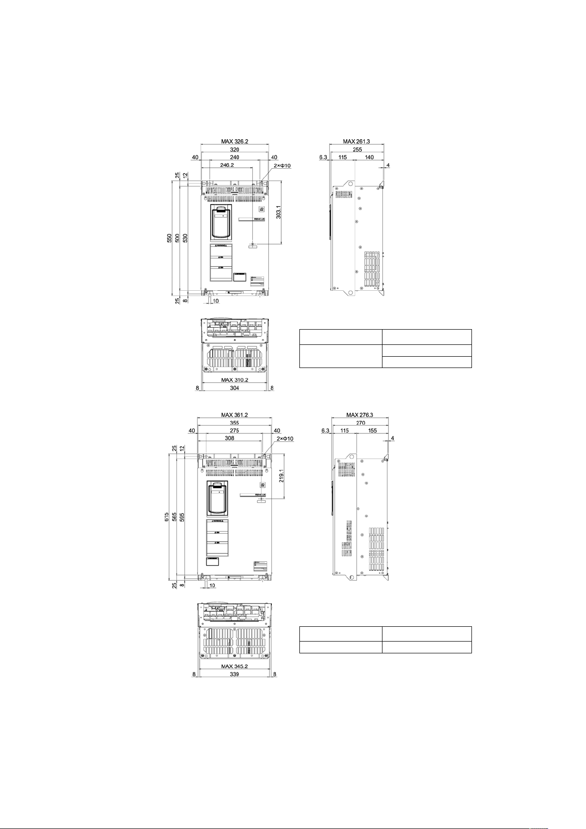
7-8
Power supply voltage
Inverter type
Three-phase 400V
FRN0060LM2A-4□
FRN0075LM2A-4□
Power supply voltage
Inverter type
Three-phase 400V
FRN0091LM2A-4□
Page 59

8-1
Chapter 8 CONFORMITY WITH STANDARDS
8.1 Compatibility with Revised EMC Directive and Low Voltage Directive
In the revised EMC Directive (2014/30/EU ) and Low Voltage Directive (2014/35/EU ), it is necessary to clearly state
the name and the address of manufacturers and importers to enhance traceability. Importers shall be indicated as
follows when exporting products from Fuji Electric to Europe.
(Manufacturer)
Fuji Electric Co., Ltd
5520, Minami Tamagaki-cho, Suzuka-city, Mie 513-8633, Japan
(Importer in Europe)
Fuji Electric Europe GmbH
Goethering 58, 63067 Offenbach / Main, Germany
<Precaution when exporting to Europe>
●Not all Fuji Electric products in Europe are necessarily imported by the above importer. If any Fuji Electric products are
exported to Europe via another importer, please ensure that the importer is clearly stated by the customer.
Page 60

8-2
8.2 Compliance with European Standards
The CE marking on Fuji products indicates that they comply with the essential requirements of the
Electromagnetic Compatibility (EMC) Directive, Low Voltage Directive, Machinery Directive and Lift Directive
which are issued by the Council of the European Communities.
The amount of current leaked by internal EMC-compatible filter is significantly large, and therefore a
check should be performed to determine whether the power supply system is affected.
! Refer to Chapter 8.4.3 below for details on EMC filter leakage current values.
The products comply with the following standards
Table 8.1 Product Standards Compliance
FRN0011LM2A-7□,
FRN0018LM2A-7□
FRN0006LM2A-4□ to
FRN0025LM2A-4□
FRN0032LM2A-4□ to
FRN0091LM2A-4□
Low Voltage
Directive
IEC/EN 61800-5-1
EMC Directives
IEC/EN 61800-3
Immunity : Second environment
(Industrial)
Emission: Category C2
IEC/EN 61800-3
Immunity :
Second environment
(Industrial)
Emission: Category C3
IEC/EN 61326-3-1
Machinery
Directive
EN ISO 13849-1 :Cat. 3 / PL=e
IEC/EN 61508-1 to -7 :SIL3
IEC/EN 61800-5-2 :SIL3 , Safety function: Safe Torque Off (STO)
IEC/EN 62061 :SILCL3
Lift Directive
EN 81-1(in extract), EN 81-2(in extract)
EN 81-20(in extract)
EN 12015,EN 12016
Note
A box (") replaces an alphabetic letter depending on the shipping destination.
"Shipping destination: E (Europe) or A (Asia)
8.3 Conformity to the Low Voltage Directive in the EU
To use Fuji inverters as a product conforming to the Low Voltage Directive in the EU, refer to guidelines given
on pages vii to viii.
Page 61

8-3
8.4 Compliance with EMC Standards
8.4.1 General
The CE marking on inverters does not ensure that the entire equipment including our CE-marked products is
compliant with the EMC Directive. Therefore, CE marking for the equipment shall be the responsibility of the
equipment manufacturer. For this reason, Fuji Electric’s CE mark is indicated under the condition that the
product shall be used within equipment meeting all requirements for the relevant Directives. Instrumentation of
such equipment shall be the responsibility of the equipment manufacturer.
Generally, machinery or equipment includes not only our products but other devices as well. Manufacturers,
therefore, shall design the whole system to be compliant with the relevant Directives.
EMC certification testing is performed using the following wiring distances between the inverter and
motor (shielded wire):
・FRN0006LM2A-4□ to FRN0091LM2A-4□
・FRN0011LM2A-7
□, FRN0018LM2A07□
:10m
8.4.2 Recommended installation procedure
To make the machinery or equipment fully compliant with the EMC Directive, the motor and inverter have to be
wired by certified technicians in strict accordance with the procedure given below.
1) Use shielded wires for the motor cable and route the cable as short as possible. Firmly clamp the shield to
the specified point or the grounded metal plate inside the inverter. Further, connect the shielding layer
electrically to the grounding terminal of the motor.
2) For connection to inverter's control terminals and for connection of the RS-485 communication or CAN-Bus
signal cable, use shielded wires. Clamp the shields firmly to the grounded metal plate.
3) Place the inverter on a grounded metal plate such as the surface of a panel, as shown in Figure 8.1. If
radiated noise emissions exceed the standard, place the inverter and any peripheral equipment inside a
metal control panel.
Figure 8.1 Installation inside a Panel
4) If radiated noise emissions exceed the requirement by the standard, place a ferrite core on the input side of
the inverter, as shown in Figure 8.2
FRENIC-Lift
Ferrite
Core
L1/R
L2/S
L3/T
G
From
Power
Supply
Figure 8.2 Installation for ferrite core
FRENIC-LIFT
Page 62

8-4
8.4.3 Leakage current of the EMC filter
This product has built-in EMC compliant filter that contains grounding capacitors for noise suppression which
increase the leakage current. Check whether there is no problem with electrical systems. When using this
product, the leakage current listed in Table 8.2 is added. Before adding this product, consider whether the
additional leakage current is allowable in the context of the overall system design.
Table 8.2 Leakage Current of FRENIC Lift
Input power
Inverter type
Leakage
current (mA)
Input power
Inverter type
Leakage
current (mA)
Three-phase
400 V
FRN0006LM2A-4□
15
One-phase
200 V
FRN0011LM2A-7□
15
FRN0010LM2A-4□
FRN0018LM2A-7□
FRN0015LM2A-4□
FRN0019LM2A-4□
FRN0025LM2A-4□
FRN0032LM2A-4□
FRN0039LM2A-4□
3
FRN0045LM2A-4□
FRN0060LM2A-4□
8
FRN0075LM2A-4□
FRN0091LM2A-4□
* Calculated based on these measuring conditions
400V series: 400V, 50Hz with neutral grounding, and an interphase voltage unbalance ratio of 2%.
200V series: 230V, 50Hz with phase grounding.
Note: A box (") replaces an alphabetic letter depending on the shipping destination.
"Shipping destination: E (Europe) or A (Asia)
Page 63

8-5
8.5 Harmonic Component Regulation in the EU
8.5.1 General comments
When general-purpose industrial inverters are used in the EU, the harmonics emitted from inverters to the
power lines are strictly regulated as stated below.
If an inverter whose rated input is 1 kW or less is connected to the public low-voltage power supply, it is
regulated by the harmonics emission regulation IEC/EN 61000-3-2. If an inverter whose input current is above
16 A and 75 A or below is connected to the public low-voltage power supply, it is regulated by the harmonics
emission regulation IEC/EN 61000-3-12.
Note that connection to the industrial low-voltage power lines is an exception. See Figure 8.3.
Medium voltage
The inverter connected here is
subject to the harmonics
regulation. If the harmonics
flowing into the power source
exceeds the regulated level,
permission by the local power
supplier will be needed.
Inverter
Medium-tolow voltage
transformer
Public low-voltage
power supply
User A
Inverter
The inverter connected
here is not subject to the
harmonics regulation.
User B
User C
Medium-to-low
voltage transformer
Industrial
low-voltage
power supply
Figure 8.3 Power Source and Regulation
8.5.2 Compliance with IEC/EN 61000-3-12
To bring the inverters FRN0006LM2A-4□ to FRN0091LM2A-4□ into compliance with IEC/EN 61000-3-12,
install an optional DC reactor and connect the inverters to a power supply whose short-circuit ratio Rsce is 120
or above.
Page 64

8-6
8.6 Compliance with Functional Safety Standard
8.6.1 General
In FRENIC-Lift series of inverters, opening the hardware circuit between terminals [EN1]-[PLC] or between
terminals [EN2]-[PLC] stops the output transistor, coasting the motor to a stop (EN: Enable input). This is the
Safe Torque Off (STO) compliant with Functional Safety Standard EN/IEC 61800-5-2.
Using the Safe Torque Off (STO) function eliminates the need of external safety circuit breakers (i.e. magnetic
contactors) while conventional inverters need those breakers to set up the system compliant to Functional
Safety Standard.
Table 8.3 shows the functional safety function performance.
Table 8.3 Functional Safety Function Performance
EN ISO 13849-1
Category
3
Performance level
e
DCave
>= 90% (medium)
Response time
(Safety reaction time)
<= 50 ms
(Delay time from when either of terminals [EN1]
and [EN2] comes OFF to STO)
MTTFd for each channel
>= 30 years
EN 61508-1 to -7
EN 61800-5-2
Safety Function (Stop function)
STO (Safe Torque Off)
SIL (Safety integrity level)
SIL3 (Type B)
HFT (Hardware Fault Tolerance)
1
SFF (Safe Failure Fraction)
>= 90%
PFDave
< 1.0 ☓ 10-3
(Average of Probability of Failure on Demand)
PFH
< 1.0 ☓ 10-7
(Probability of a dangerous random hardware
failure per hour)
Proof test interval (Lift time)
10 years
• The output shutdown function of this inverter uses the Safe Torque Off (STO) function prescribed in IEC/EN
61800-5-2 so that it does not completely shut off the power supply to the motor electrically. Depending upon
applications, therefore, additional measures are necessary for safety of end-users, e.g., brake function that locks
the machinery and motor terminal protection that prevents possible electrical hazard(s).
• The output shutdown function does not completely shut off the power supply to the motor electrically. Before
starting wiring or maintenance jobs, therefore, be sure to disconnect the input power to the inverter and wait at
least five minutes.
• When a permanent magnet synchronous motor (PMSM) is coasting to a stop caused by the output shutdown
function, voltage is applied to its terminals. Before starting maintenance, inspection or wiring, therefore, be sure
to check that the PMSM is completely stopped.
An electric shock could occur.
Page 65

8-7
Enable terminals and peripheral circuit, and internal circuit configuration
Figure 8.5 FRENIC-Lift Inverters compliant with EN 81-1 12.7.3 a)
EN81-20 5.9.2.5.4 d) or EN81-20 5.9.3.4.2 d)
Take the following measures for synchronous motor drive.
• If a PMSM is rotated with an external force, separate the PMSM and inverter with a switching device, or short
PMSM output terminal U, V, and W.
• If a PMSM is rotated with an external force, there is a risk that the inverter will be damaged by energy generated by
the motor side.
Risk of breakage.
Safety circuit breakers
complying with more than EN ISO 13849-1 Cat.3
External safety switch complying with
more than EN ISO 13849-1 Cat.3, PL-e
EN62061/EN61508 SIL3
M
3~
Co nven ti ona l In ver te r
Power
supply
Reset
“Enable” input
Emergency Stop
FRENIC-Lif t(LM 2) Inverter
[L1/R]
[L2/S]
[L3/T]
[PLC]
[EN1]
[EN2]
[Y*]
[CMY]
Reset
Emergency
Stop
6
“Enable”
input
Output IGBTs
Safety
Related
Circuit
[U]
[V ]
[W]
External safety switch
with higher compliance than
EN ISO 13849-1 Cat.3, PL-e
EN62061/EN61508 SIL3
Power
supply
M
3~
“DECF”
Note) Y* terminal set to DECF function..
Figure 8.4 Conventional Inverters compliant with EN 81-1 12.7.3 a)
EN81-20 5.9.2.5.4 d) or EN81-20 5.9.3.4.2 d)
Page 66

8-8
Table 8.4 Operation of STO Functional Safety Function
Digital input signals
Alarm ECF
Digital output signal
Inverter status
[EN1]
[EN2]
[Y*] (DECF)
Shorted
Shorted
No issue
ON
Ready to run
Issue
OFF
Output shutdown (STO)
Opened
Opened
No issue
ON
Output shutdown (STO)
Issue
OFF
Output shutdown (STO)
Shorted
Opened
Issue
OFF
Output shutdown (STO)
Opened
Shorted
Issue
OFF
Output shutdown (STO)
8.6.2 Notes for compliance to Functional Safety Standard
1) Wiring for terminals [EN1] (Enable input 1) and [EN2] (Enable input 2)
- [EN1]/[EN2] and [PLC] are terminals prepared for connection of safety related wires; therefore, careful wiring
should be performed to ensure that no short-circuit(s) can occur to these terminals.
- For opening and closing the hardware circuit between terminals [EN1]/[EN2] and [PLC], use safety approved
components such as safety switches and safety relays that comply with EN ISO13849-1 Cat. 3 PL=e or
higher to ensure a complete shutoff.
- Input cables of [EN1] and [EN2] must be segregated in different electrical conductors installed inside
different conduits, otherwise the use of independent shielded cables is a must. The armor of the conduit or
the shield must be connected to CM terminal.
- It is the responsibility of the machinery manufacturer to guarantee that a short-circuiting or other fault does
not occur in wiring of external safety components between terminals [EN1]/[EN2] and [PLC].
Fault Examples:
• Terminals [EN1]/[EN2] and [PLC] are short-circuited due to the wiring being caught in the door of the
control panel so that a current continues to flow in terminal [EN1]/[EN2] although the safety component is
OFF and therefore the safety function will/may NOT operate
• The wiring is in contact with any other wire so that a current continues to flow in terminal [EN1]/[EN2] and
therefore the safety function will/may NOT operate
2) Notes for Safe Torque Off (STO) function
- When configuring the product safety system with this Safe Torque Off (STO) function, make a risk
assessment of not only the external equipment and wiring connected to terminals [EN1] and [EN2] (Enable
input 1 and Enable input 2) but also the whole system including other equipment, devices and wiring against
the product safety system required by the machinery manufacturer under the manufacturer's responsibility in
order to confirm that the whole system conforms to the product safety system required by the machinery
manufacturer.
In addition, as preventive maintenance, the machinery manufacturer must perform periodical inspections to
check that the product safety system properly functions.
- To bring the inverter into compliance with Functional Safety Standard, it is necessary to install the inverter
inside a control panel with the enclosure rating of IP54 or above.
Page 67

8-9
- To bring the inverter into compliance with Functional Safety Standard, it is necessary to bring it into
compliance with European Standards EN61800-5-1 and EN61800-3.
- This Safe Torque Off (STO) function coasts the motor to a stop.
- In case of diagnostics with a safe PLC, short pulses with a duration less than 1 ms should be input to
terminals [EN1] and [EN2].
- The safety shutdown circuit between input terminals [EN1] and [EN2] sections and inverter's output
shutdown section is a redundant circuit so that an occurrence of a single fault does not prevent the Safe
Torque Off (STO) function.
If a single fault is detected in the safety shutdown circuit, the inverter coasts the motor to a stop even with
the terminal [EN1]-[PLC] and [EN2]-[PLC] states being ON, as well as outputting an alarm to external
equipment. Note that the alarm output function is not guaranteed to all of single faults. It is compliant with
EN ISO13849-1 Cat. 3 PL=e.
- This Safe Torque Off (STO) function may not completely shut off the power supply to the motor electrically.
Before starting wiring or maintenance jobs, be sure to disconnect the input power to the inverter and wait at
least 5 minutes.
3) Test of Safe Torque Off (STO) function
- [EN1]/[EN2] and [PLC] must be turned off for diagnostics at least one time per hour. Then [EN1]/[EN2] and
[PLC] must be kept off for at least 2 seconds.
- Main power supply must be shut off (auxiliary power supply of the control circuit can be supplied) at least
one time per one day.
Page 68

8-10
8.6.3 Inverter output state when Safe Torque Off (STO) is activated
Turning the emergency stop button ON turns EN1 and EN2 OFF, bringing the inverter into the Safe Torque Off
(STO) state.
Figure 8.6 shows the timing scheme to apply when the emergency stop button is turned OFF with the inverter
being stopped. Input signals to EN1 and EN2 become ON, making the inverter ready to run.
Figure 8.6 Inverter Output State when the Emergency Stop Button is Turned OFF with the Inverter Being stopped
InputtoEN 1/EN2
R un
R uncom m and
Inverteroutput
ON
OFF
W aitforarun
com m and
R unning
Em ergencystop
button
OFFON
Stop
SafeTorqueOff
(STO)
Stop
ON
SafeTorqueOff
(STO)
OFF
W aitforarun
com m and
Page 69

8-11
Figure 8.7 shows the timing scheme to apply when the emergency stop button is turned ON with the inverter
running. Input signals to EN1 and EN2 go OFF, bringing the inverter into the Safe Torque Off (STO) state and
coasting the motor to a stop.
Figure 8.7 Inverter Output State when the Emergency Stop Button is Turned ON with the Inverter Running
InputtoE N1/EN2
R un
R uncom m and
Inverteroutput
ON OFF
R unning
Em ergencystop
button
OFF ON
Stop
SafeTorqueOff
(STO )
Page 70

8-12
8.6.4 ECF alarm (caused by logic discrepancy) and inverter output state
Figure 8.8 shows the timing scheme to apply when EN1 and EN2 inputs are not concordant, so that an alarm
ECF occurs.
Turning the emergency stop button ON turns EN1 and EN2 inputs OFF, which usually brings the inverter into
the Safe Torque Off (STO) state. If the discrepancy of the EN1 and EN2 inputs is within 50 ms, no alarm occurs;
if it is longer than 50 ms, the inverter interprets it as a logic discrepancy, outputting the alarm ECF. The alarm
can be cleared by restarting the inverter.
To diagnose the EN terminals circuit appropriately, when turning EN1/EN2 inputs ON and OFF, keep the ON
and OFF time for at least 2 s.
InputtoE N1
R un
R uncom m and
Inverteroutput
ON
OFF
R unning
Em ergencystop
button
OFF ON
Stop
SafeT orqueO ff
(STO)
InputtoE N2
ON
OFF
50ms
ECF
alarm
Noalarm A larm issued
50ms
ON
OFF
OFF
PowerO FF
OFF
ON
ON
PowerO N
Noalarm A larm issued
SafeT orqueO ff
(STO)
>=2s
>=2s
Figure 8.8 ECF Alarm (Caused by Logic Discrepancy) and Inverter Output State
Page 71

8-13
8.7 Compliance with Canadian and U.S. Standards (CSA certification)
8.7.1 General
The inverters with CSA “C/US” marking are certified for both U.S. and Canadian markets, to the applicable U.S.
and Canadian standards.
The products comply with the following standards
Table 8.5 Product Standards Compliance
FRN0006LM2A-4□ to FRN0091LM2A-4□
FRN0011LM2A-7□, FRN0018LM2A-7□
Canadian
standards
Can/CSA C22.2 No.14-13 : Industrial Control Equipment
CSA C22.2 No.274-13 : Adjustable speed drives
U.S. standards
UL 508 C (3rd Edition) : Power Conversion Equipment
Note
A box (") replaces an alphabetic letter depending on the shipping destination.
"Shipping destination: E (Europe) or A (Asia)
8.7.2 Considerations when using FRENIC-Lift (LM2A) in systems to be certified by CSA
If you want to use the FRENIC-Lift (LM2A) of inverters as a part of U.S. and Canadian standards certified
product, refer to the related guidelines described on pages ix to xi.
Page 72

Instruction Manual
First Edition, February 2015
Fifth Edition, February 2016
Fuji Electric Co., Ltd.
The purpose of this instruction manual is to provide accurate information in handling, setting up and operating of
the FRENIC-Lift LM2A series of inverters. Please feel free to send your comments regarding any errors or
omissions you may have found, or any suggestions you may have for generally improving the manual.
In no event will Fuji Electric Co., Ltd. be liable for any direct or indirect damages resulting from the application of
the information in this manual.
Page 73

Fuji Electric Co., Ltd.
Gate City Ohsaki, East Tower, 11-2, Osaki 1-chome, Shinagawa-ku, Tokyo 141-0032, Japan
Phone: +81 3 5435 7058 Fax: +81 3 5435 7420
URL http://www.fujielectric.com/
 Loading...