

Page 1
High Performance Inverter
Solar Pumping
Instruction Manual
Thank you for purchasing our multifunction FRENIC-Ace series of inverters.
• This product is desig ne d to dri ve a thr e e-phase motor under var iab le s p eed c ontr ol. Read through
this user's manual and become familiar with the handling procedure for correct use.
• Improper handling might result in incorrect operation, a short life, or even a failure of this product as
well as the motor.
• Deliver this manual t o the end user of this product. Kee p this manual in a safe place until t his
product is discarded.
• For how to use an optional device, refer to the instruction and installation manuals for that optional
device.
Jde085-00031a
Page 2

Copyright © 2014 Fuji Electric Co., Ltd.
All rights reserved.
No part of this publ ication m ay be reproduc ed or copi ed without pr ior writte n perm ission
from Fuji Electric Co., Ltd.
All products and company nam es m entioned in t his manua l are tr adem ark s or r egistered
trademarks of their respective holders.
The information contained herein is subject to change without prior notice for
improvement.
The purpose of this user's manual is to provide accurate information in handling, setting up
and operating of the FRENIC-Ace series of inverters. Please feel free to send your
comments regarding any errors or omissions you may have found, or any suggestions you
may have for generally improving the manual.
In no event will Fuji Electric Co., Ltd. be liable for any direct or indirect damages resulting
from the application of the information in this manual.
Page 3

Preface
Thank you for purchasing our m ultifunction FRENIC-Ace series of inverters for Solar Pum ping
application. This product is designed to drive three-phase induction motors or three-phase
permanent magnet synchronou s m otors under variable speed control.
This manual provides the i nformation on the FRENIC-Ace series of inverters including its
operating procedure when used in Solar Pumping application. B efore use, carefully read this
manual for proper use. Improper ha ndling might res ult in incorrect operat ion, a short life, or ev en a
failure of this product as well as t he motor .
The table below lists the other materials related to the use o f the FRENIC-Ace. Read the m in
conjunction with this manual if necessary.
Name Material No. Description
Catalog
24A1-E-0042
Product scope, features, specifications, external drawings,
and options of the product
RS
-485 Communication User' s
Manual
24A7-E-0021*
Overview of functions implemented by using FRENIC-Ace
RS-485 communications facility, its communications
specifications, Modbus RTU/Fuji general-p urpo se inv ert er
protocol, function codes and related data formats
User
’s Manual for China model 24A7-E-0043x This manual is written in English.
User
’s Manual for China model. 24A7-C-0043x This manual is written in simplified Chinese.
User
’s Manual for Japanese
model.
24A7-J-0043x This manual is written in Japanese.
*Available soon
x Is the index letter that indicates the manual version. Please refer to the latest one.
The materials are subject to c hange without notice. Be sure to obtain the latest editions for use.
i
Page 4

Introduction of FRENIC Ace Solar Pumping
In the Solar Pumping applicat ion the inv ert er drives an electrical motor (pump), while the power is
supplied usually from a PV panel. FRENIC Ace Solar Pumping inverter speci fication is equipped
with dedicated functions for t he cor r ect oper ation under these spec ia l conditions:
Solar Panel voltage set point calculation at every start (depending on current irradiance
and panel temperatur e)
True M aximum Power Point Tracking (MPP T) function
Detection of sudden changes of conditions (irradiance)
Stop criteria selectable (frequency and/or power)
Star t c rit er ia by s olar panel voltage and time (to limit the number of starts)
Dry pump detection funct i on
Water t ank maximum level detection fu nc t io n
Low power detection funct ion
Two sets of PID gains
ii
Page 5

Index
Chapter 1 SAFETY PRECAUTIONS
This chapter describes the safety precautions that should be considered during t he w hol e li fe o f
the product.
Chapter 2 INSTALLATION AND WIRING
This chapter describes the i mportant points in installing and wiring the inver t er.
Chapter 3 OPERATION USING THE KEYP AD
This chapter describes keypad operation of the inv er t er.
Chapter 4 SET UP PROCEDURE
This chapter describes the set up pr ocedure of FRENIC Ace for Solar Pumping application.
Chapter 5 FUNCTION CODES
This chapter explains the function codes relevant for Sol ar pumping application. For other
parameters not descr ib ed in this manual please refe r t o FRE NIC Ace User M anual.
Chapter 6 TROUBLESHOOTING
This chapter describes troubleshooting procedures t o be fo llowed when the invert er malfunctions
or detects an alarm or a light alarm condition. In this c hapter , first chec k whether any alarm code o r
the "light alarm" indicatio n (
l-al
) is displayed or not, and then pro ceed to the troubleshooting items.
Chapter 7 SPECIFICATIONS
This chapter describes the pow er circuit input and output r at ings and basic constructive
specifications of FRENIC Ace standard model.
iii
Page 6
1-1
Chapter 1 SAFETY PRECAUTIONS
Read this manual thoroughly before proceeding with installation, connections (wiring), operation, or maintenance
and inspection. Ensure you have sound knowledge of the device and familiarize yourself with all safety information
and precautions before proceeding to operate the inverter.
Safety precautions are classified into the following two categories in this manual.
Failure to heed the information indicated by this symbol may lead to dangerous
conditions, possibly resulting in death or serious bodily injuries.
Failure to heed the information indicated by this symbol may lead to dangerous
conditions, possibly resulting in minor or light bodily injuries and/or substantial
property damage.
Failure to heed the information contained under the CAUTION title can also result in serious consequences. These
safety precautions are of utmost importance and must be observed at all times.
Application
• The FRENIC-Ace is designed to drive a three-phase induction motor. Do not use it for single-phase motors
or for other purposes.
Fire or an accident could occur.
• The FRENIC-Ace may not be used for a life-support system or other purposes directly related to the human
safety.
• Though the FRENIC-Ace is manufactured under strict quality control, install safety devices for applications
where serious accidents or property damages are foreseen in relation to the failure of it.
An accident could occur.
Installation
• Install the inverter on a base made of metal or other non-flammable material.
Otherwise, a fire could occur.
• Do not place flammable object nearby.
Doing so could cause fire.
• Inverters FRN0085E2■-4G or above, whose protective structure is IP00, involve a possibility that a human
body may touch the live conductors of the main circuit terminal block. Inverters to which an optional DC
reactor is connected also involve the same. Install such inverters in an inaccessible place.
Otherwise, electric shock or injuries could occur.
• Do not support the inverter by its front cover during transportation.
Doing so could cause a drop of the inverter and injuries.
• Prevent lint, paper fibers, sawdust, dust, metallic chips, or other foreign materials from getting into the
inverter or from accumulating on the heat sink.
• When changing the positions of the top and bottom mounting bases, use only the specified screws.
Otherwise, a fire or an accident might result.
• Do not install or operate an inverter that is damaged or lacking parts.
Doing so could cause fire, an accident or injuries.
Page 7

1-2
Wiring
• If no zero-phase current (earth leakage current) detective device such as a ground-fault relay is installed in
the upstream power supply line, in order to avoid the entire power supply system's shutdown undesirable to
factory operation, install a residual-current-operated protective device (RCD)/earth leakage circuit breaker
(ELCB) individually to inverters to break the individual inverter power supply lines only.
Otherwise, a fire could occur.
• When wiring the inverter to the power source, insert a recommended molded case circuit breaker (MCCB) or
residual-current-operated protective device (RCD)/earth leakage circuit breaker (ELCB) (with overcurrent
protection) in the path of each pair of power lines to inverters. Use the recommended devices within the
recommended current capacity.
• Use wires in the specified size.
• Tighten terminals with specified torque.
Otherwise, a fire could occur.
• When there is more than one combination of an inverter and motor, do not use a multicore cable for the
purpose of handling their wirings together.
• Do not connect a surge killer to the inverter's output (secondary) circuit.
Doing so could cause a fire.
• Be sure to connect an optional DC reactor (DCR) when the capacity of the power supply transformer exceeds
500 kVA and is 10 times or more the inverter rated capacity.
Otherwise, a fire could occur.
• Ground the inverter in compliance with the national or local electric code.
• Be sure to ground the inverter's grounding terminals G.
Otherwise, an electric shock or a fire could occur.
• Qualified electricians should carry out wiring.
• Be sure to perform wiring after turning the power OFF.
Otherwise, an electric shock could occur.
• Be sure to perform wiring after installing the inverter unit.
Otherwise, an electric shock or injuries could occur.
• Ensure that the number of input phases and the rated voltage of the product match the number of phases and
the voltage of the AC power supply to which the product is to be connected.
Otherwise, a fire or an accident could occur.
• Do not connect the power supply wires to output terminals (U, V, and W).
• When connecting a DC braking resistor (DBR), never connect it to terminals other than terminals P(+) and
DB.
Doing so could cause fire or an accident.
• In general, sheaths of the control signal wires are not specifically designed to withstand a high voltage (i.e.,
reinforced insulation is not applied). Therefore, if a control signal wire comes into direct contact with a live
conductor of the main circuit, the insulation of the sheath might break down, which would expose the signal
wire to a high voltage of the main circuit. Make sure that the control signal wires will not come into contact with
live conductors of the main circuit.
Doing so could cause an accident or an electric shock.
• Before changing the switches or touching the control circuit terminal symbol plate, turn OFF the power and
wait at least five minutes for inverters FRN0115E2■-2G / FRN0072E2■-4G or below, or at least ten
minutes for inverters FRN0085E2■-4G or above. Make sure that the LED monitor and charging lamp are
turned OFF. Further, make sure, using a multimeter or a similar instrument, that the DC link bus voltage
between the terminals P(+) and N(-) has dropped to the safe level (+25 VDC or below).
Otherwise, an electric shock could occur.
• The inverter, motor and wiring generate electric noise. Be careful about malfunction of the nearby sensors
and devices. To prevent them from malfunctioning, implement noise control measures.
Otherwise an accident could occur.
Page 8
1-3
Operation
• Be sure to mount the front cover before turning the power ON. Do not remove the cover when the inverter
power is ON.
Otherwise, an electric shock could occur.
• Do not operate switches with wet hands.
Doing so could cause electric shock.
• If the auto-reset function has been selected, the inverter may automatically restart and drive the motor
depending on the cause of tripping. Design the machinery or equipment so that human safety is ensured at
the time of restarting.
Otherwise, an accident could occur.
• If the stall prevention function (current limiter), automatic deceleration (anti-regenerative control), or
overload prevention control has been selected, the inverter may operate with acceleration/deceleration or
frequency different from the commanded ones. Design the machine so that safety is ensured even in such
cases.
• The key on the keypad is effective only when the keypad operation is enabled with function code F02 (=
0, 2 or 3). When the keypad operation is disabled, prepare an emergency stop switch separately for safe
operations.
Switching the run command source from keypad (local) to external equipment (remote) by turning ON the
"Enable communications link" command LE disables the key. To enable the key for an emergency
stop, select the STOP key priority with function code H96 (= 1 or 3).
• If any of the protective functions have been activated, first remove the cause. Then, after checking that the
all run commands are set to OFF, release the alarm. If the alarm is released while any run commands are set
to ON, the inverter may supply the power to the motor, running the motor.
Otherwise, an accident could occur.
• If you enable the "Restart mode after momentary power failure" (Function code F14 = 3 to 5), then the
inverter automatically restarts running the motor when the power is recovered.
Design the machinery or equipment so that human safety is ensured after restarting.
• If the user configures the function codes wrongly without completely understanding this User's Manual, the
motor may rotate with a torque or at a speed not permitted for the machine.
• Starting auto-tuning involves motor rotation. Sufficiently check that motor rotation brings no danger
beforehand.
An accident or injuries could occur.
• Even if the inverter has interrupted power to the motor, if the voltage is applied to the main circuit input
terminals L1/R, L2/S, L3/T, L1/L and L2/N, voltage may be output to inverter output terminals U, V, and W.
• Even if the motor is stopped due to DC braking or preliminary excitation, voltage is output to inverter output
terminals U, V, and W.
An electric shock may occur.
• The inverter can easily accept high-speed operation. When changing the speed setting, carefully check the
specifications of motors or equipment beforehand.
Otherwise, injuries could occur.
• Do not touch the heat sink and braking resistor because they become very hot.
Doing so could cause burns.
• The DC brake function of the inverter does not provide any holding mechanism.
Injuries could occur.
• Ensure safety before modifying the function code settings.
Run commands (e.g., "Run forward" FWD), stop commands (e.g., "Coast to a stop" BX), and frequency
change commands can be assigned to digital input terminals. Depending upon the assignment states of
those terminals, modifying the function code setting may cause a sudden motor start or an abrupt change in
speed.
• When the inverter is controlled with the digital input signals, switching run or frequency command sources
with the related terminal commands (e.g., SS1, SS2, SS4, SS8, Hz2/Hz1, Hz/PID, IVS, and LE) may cause
a sudden motor start or an abrupt change in speed.
• Ensure safety before modifying customizable logic related function code settings (U codes and related
function codes) or turning ON the "Cancel customizable logic" terminal command CLC. Depending upon the
settings, such modification or cancellation of the customizable logic may change the operation sequence to
cause a sudden motor start or an unexpected motor operation.
An accident or injuries could occur.
Page 9

1-4
Maintenance and inspection, and parts replacement
• Before proceeding to the maintenance/inspection jobs, turn OFF the power and wait at least five minutes
for inverters FRN0115E2■-2G / FRN0072E2■-4G or below, or at least ten minutes for inverters
FRN0085E2■-4G or above. Make sure that the LED monitor and charging lamp are turned OFF. Further,
make sure, using a multimeter or a similar instrument, that the DC link bus voltage between the terminals
P(+) and N(-) has dropped to the safe level (+25 VDC or below).
Otherwise, an electric shock could occur.
• Maintenance, inspection, and parts replacement should be made only by qualified persons.
• Take off the watch, rings and other metallic objects before starting work.
• Use insulated tools.
Otherwise, an electric shock or injuries could occur.
• Never modify the inverter.
Doing so could cause an electric shock or injuries.
Disposal
• Treat the inverter as an industrial waste when disposing of it.
Otherwise injuries could occur.
GENERAL PRECAUTIONS
Drawings in this manual may be illustrated without covers or safety shields for explanation of detail parts. Restore
the covers and shields in the original state and observe the description in the manual before starting operation.
Icons
The following icons are used throughout this manual.
This icon indicates information which, if not heeded, can result in the inverter not operating to full efficiency,
as well as information concerning incorrect operations and settings which can result in accidents.
This icon indicates information that can be useful when performing certain settings or operations.
This icon indicates a reference to more detailed information.
Page 10

Page 11

Chapter 2 INSTALLATION AND WIRING
2.1 Installation
(1) Installation Environment
Please install FRENIC-Ace in locations which meet the conditions specified in “Chapter 1 1.3.1 Usage
environment” of the User Manual.
(2) Installation Surface
Please install the inver ter on non-combustible matter such as metals. Also, do not mount it up si de down or
horizontally.
Install on non-combustible matter such as metals.
Risk of fire exists
(3) Surrounding Space
Secure the space shown in Figure 2.1
-1 and Table 2.1-1. When
enclosing
FRENIC-Ace in cabinets, be sure to provide adequate
ventilation
to the cabinet, as the surround ing te mpera ture ma y rise. Do
not contain
it in small enclosures with low heat dissipation capacity.
Installation of Multiple Inverters
When installing 2 or m
ore units in the same equipment or cabinet,
generally mount
them to the side of each other, not above each other.
When the inverters are mounted
above each other, attach partitioning
boards to prevent
that the heat dissipated from the lower inverter to
affect
s the upper inverter.
For
types FRN0072E2-4G, FRN0220E2-2G or below and for
ambient temperature below 4
0°C only, the units can be installed
side by
side without any spacing between them
(30°C or lower for ND and HD).
Table 2.1-1 Surrounding Space mm (inch)
Applicable Capacity A B C
200 V class: FRN0001 to 0220E2-2G
200 V class: FRN0001 to 0012E2-7G
400 V class: FRN0002 to 0072E2-4G
10
(0.39)
100
(3.9)
0
*1
400 V class: FRN0085 to 0590E2-4G
50
(1.97)
100
(3.9)
*1 A clearance of 50 mm is required to use RJ45 connector .
C: Space in front of the inverter unit
Installation with External Cooling
The
external cooling installation reduces the generated heat inside the
panel
by dissipating approximately 70% of the total heat generated
(total heat loss)
by mounting the cooling fins protruding outside the
equipment or cabinet.
Installation with external co
oling is possible for types FRN0069E2■-2G
and
FRN0072E2■-4G or below by adding attachments (optional) for
external cooling,
and for types FRN0085E2■-4G or above by moving
the
mounting bases.
Figure 2.1-2 Installation with External
Cooling
Please refer to User Manual Chapter 11 Item 11.15 for the external
dimensions
drawing of the external cooling attachment (optional).
Prevent lint, wastepaper, wood shavings, dust, metal scrap, and
other foreign material from entering the inv erter or fro m att ac hing to
the cooling fins.
Risk of fire and risk of accidents exist
To install the FRN0085E2■-4G inverter with external cooling, change the mounting position of the mounting bases
following the procedure in Figure 2.1-3.
As the type and number of screws differ by inverter type, please review the following table.
Figure 2.1-1 Installation Direction
2-1
Page 12
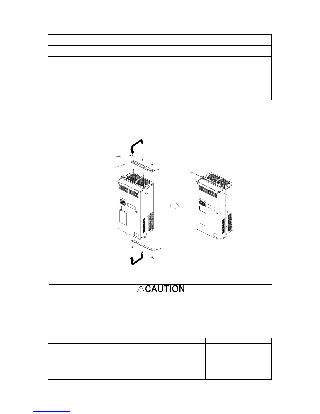
Table 2.1-2 Type and Number of Screws, and Tightening Torque
Inverter type
Mounting base fixation screw Case attachment screw
Tightening torque
Nm (Ib-in)
FRN0085E2■-4G
to FRN0168E2■-4G
M6×20 (5 screws on top,3
screws on bottom)
M6×20
(2 screws on top only)
5.8 (51.3)
FRN0203E2■-4G
M6×20 (3 screws on top and
bottom each)
M6×12
(3 screws on top only)
5.8 (51.3)
FRN0240E2■-4G
to FRN0290E2■-4G
M5×12 (7 screws on top and
bottom each)
M5×12
(7 screws on top only)
3.5 (31.0)
FRN0361E2■-4G
to FRN0415E2■-4G
M5×16 (7 screws on top and
bottom each )
M5×16
(7 screws on top only)
3.5 (31.0)
FRN0520E2■-4G
to FRN0590E2■-4G
M5×16 (8 screws on top and
bottom each)
M5×16
(8 screws on top only)
3.5 (31.0)
1) Remove all of the mounting base fixation screws and the case attachment screws on the top of the inverter.
2) Fix the mounting bases to the case attachment screw holes using the mounting base fixation screws. A few
screws should remain after changing the position of the mounting bases.
3) Change the position of the mounting bases on the bottom side following the procedure in 1) and 2).
Figure 2.1-3 Method to Change the Mounting Base Positions
Use the specified screws in changing the mounting bases.
Risk of fire and risk of accidents exist
Inverter unit installation screw size.
Select the bolt size, considering the thickness of the mounting feet and installation surface so that the bolt
protrudes from the nut by 2 threads or more.
Inverter type
Inverter fixation screw
Tightening torque Nm (Ib-in)
200V class:FRN0030/0040E2■-2G
400V class:FRN0022/0029E2■-4G
M5 (4 screws) 3.5 (31.0)
200V class:FRN0056/0069E2■-2G
400V class:FRN0037E2■-4G to RN0203E2■-4G
M8 (4 screws) 13.5 (119)
400V class:FRN0240E2■-4G to RN0415E2■-4G
M12 (4 screws)
48 (425)
400V class:FRN0520E2■-4G to RN0590E2■-4G
M12 (6 screws)
48(425)
Mounting base fixation screw
Mounting base
(upper side)
Mounting base
(lower side)
Mounting base fixation screw
Case attachment screw
2-2
Page 13

2.2 Wiring
This chapter describes the basic connection diagram alternatives for Solar Pumping application.
2.2.1 Input and output control signals.
T
able 2.2-1 describes the input control signals to the inverter.
T
able 2.2-1 Input control signals to the inverter.
INPUT DESCRIPTION SYMBOL
[12]
Water tank level analog signal. The signal from the water level sensor of the tank can
be connected to this input. The inverter will stop when the tank level becomes higher
than the level programmed in parameter U128. In order to use this signal, connect the
sensor to this input and set the desired tank level above which the pump has to stop. If
this signal is not used, set a high level in parameter U128 to avoid that the inverter
stops.
TANK LEVEL
[FWD] Run command in the FWD direction FWD
[REV] Run command in the REV direction REV
[X1]
Water tank high level digital signal. This signal is ON when the level of the tank is high.
The inverter will stop when this signal is ON. In order to use this signal, simply connect
it to the inverter; it is not required to enable it by function code.
TANK HL
T
able 2.2-2 describes the outp ut control signals f rom the inverter. The assignment of the out puts can
be changed if required. To do so, change the settings of parameters E20, E21, E27.
T
able 2.2-2 Output control signals from the inverter.
OUTPUT DESCRIPTION SYMBOL
[Y1]
Tank full output signal. This signal indicates that the water tank is full. In this situation
the inverter will not be allowed to RUN, therefore this signal is useful to
indicate/diagnose the cause of the stop.
TANK FULL
[Y2]
Low power output signal. This signal indicates that the output power is low. In case
that this signal is ON and the solar irradiance is high, it is useful to detect/diagnose that
there is a problem in the PV solar panel (for example dust, or the panel has been
covered).
LOW POWER
[30A/B/C]
This relay output is used to indicate that the inverter has tripped by alarm. The alarm
code is displayed in the inverter keypad.
ALM
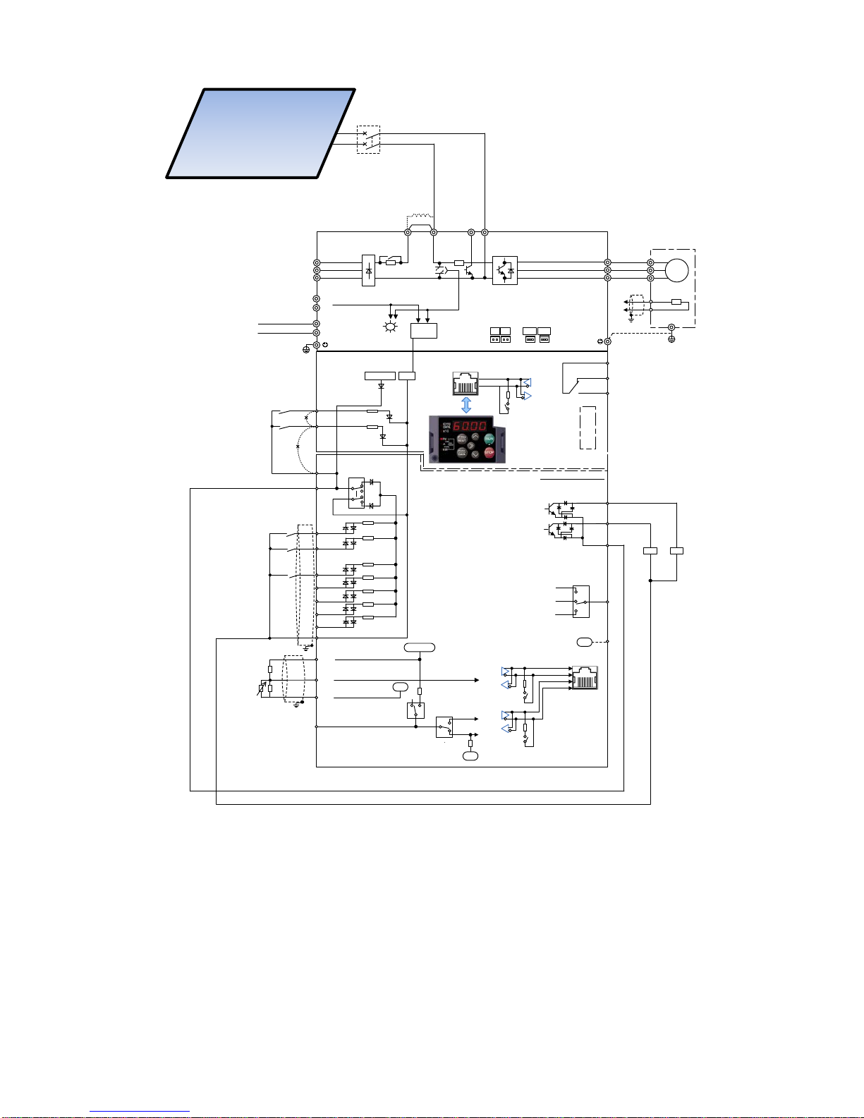
2.2.2 Inverter supplied from PV panel only
There are two alternatives of connecting the PV panel to the inverter:
(1) Connected to the DC bus terminals P(+), N(-). I n this case the pre charging ci rcuit of the inve rter is not
used. Therefore, when the PV panel is connected to the inverter, high current may flow through at the
initial stage because the inverter DC link capacitor is discharged. In order to avoid the high charging
current, there are some alternatives:
o do not make the connection when the PV panel is already receiving strong irradiat ion, or
o insert a pre-charging circuit in the connection between (+) (PV panel positive pole) and P(+), or
o use the connection alternative (2) described in following pages.
2-3
Page 14
R
F
Direct current
reactor (option)
DB
N(-)
P(+)P1
U
V
W
U
V
W
M
3~
C
L1/R
L2/S
L3/T
G
Ground
terminal
(Note 6)
TH1
THC
PTC
thermistor
To [11]
To [C1]
)
R1
T1
R0
T0
Auxiliary power
input for fan
(Note 5)
{
(Note 11)
DC/DC
(PLC)
(FWD
)
(REV
)
(X1)
(X2)
(X3)
(X4)
(X5)
(CM)
(EN1)
SINK
SOURCE
(EN2)
0V
+24VDC
<Y1>
<Y2>
<CMY>
[FM]
[11]
0V
G
E
DX+
DX-
SW6
(Note 12)
SW1
(Note 12)
(Note 8)
(Note 9)
(Note 10)
(Note 10)
Safety signal
SW5
(Note 12)
30C
30B
30A
30
Current output
(4(0) to 20 mA DC)
Voltage output
(0 to +10 V DC)
Pulse output
(25 to 32kp/s)
・Power supply voltage switching
connector “CN UX”
・Fan power supply connector “CN R” /
“CN W”
(Note 10)
CAN+
CAN-
SW6
(Note 12)
RJ45 Connector
(Note 9)
(Note 14)
(PLC)
Charge
lamp
RJ45 connector
SW2
(Note 12)
Option
connector
FMI
FMV
FMP
Motor
Data transmission and
reception (RS-485)
Keypad
Detachable terminal block
Voltage input V2
(0 to +10 V DC)
〔11〕
〔12〕
〔13〕
(Note 9)
+10VDC
Current input C1
(4(0) to 20 mA DC)
PTC thermistor input
0V
〔C1〕
Voltage input 12
(0 to +10VDC)
(0 to ±10VDC)
SW4
PTC
AI
(Note 12)
(Note 12)
SW3
C1
V2
0V
Grounding
terminal
(Note15)
(Note 15)
(Note 15)
U1
U2
CN UX
FAN
NC
CN R
CN W
Circuit breaker
(MCCB)
R1
R2
Rx
(+)
(-)
Run forward command (FWD)
Run reverse command (REV)
Tank High Level
detection (TANK HL)
Alarm output
(ALM)
Tank level
detection (TANK
LEVEL)
TANK FULL
LOW POWER
(Note 4)
Figure 2.2-1 Wiring diagram when inverter is supplied from PV panel connected to DC bus terminals.
When using this wiring please ensure that the motor is not regenerating. In case of regeneration the DC link
voltage of the inverter will rise damaging the PV panels. In order to avoid regeneration when operation command
is removed please set function code H11=1 (Coast to a stop). If regeneration cannot be avoided (for example,
controlled deceleration is always required), please use connection alternative (2) below.
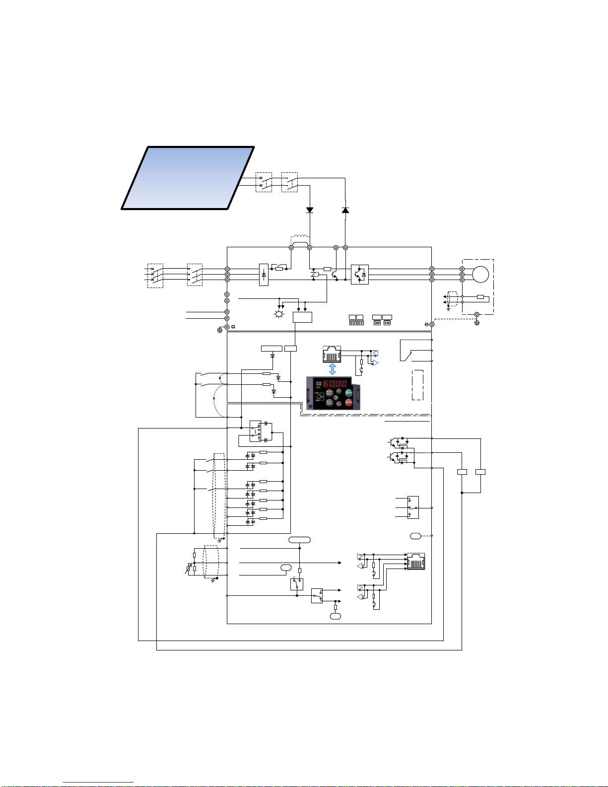
(2) Connected to the AC supp ly input s and N(-). In this case the precharging circuit of the inverter is used,
limiting the initial charging current of the inverter DC link capacitor. In this case be aware that the
maximum frequency of charging cycles is two times per hour. When using this connection the current
rating of the input rectifier must be considered. Please consult Fuji Electric to make the inverter
selection.
2-4
Page 15

R
F
Direct current
reactor (option)
DB
N(-)
P(+)P1
U
V
W
U
V
W
M
3~
C
L1/R
L2/S
L3/T
G
Ground
terminal
(Note 6)
TH1
THC
PTC
thermistor
To [11]
To [C1]
)
R1
T1
R0
T0
Auxiliary power
input for fan
(Note 5)
{
(Note 11)
DC/DC
(PLC)
(FWD)
(REV)
(X1)
(X2)
(X3)
(X4)
(X5)
(CM)
(EN1)
SINK
SOURCE
(EN2)
0V
+24VDC
Run forward command (FWD)
Run reverse command (REV)
Tank High Level
detection (TANK HL)
<Y1>
<Y2>
<CMY>
[FM]
[11]
0V
G
E
DX+
DX-
SW6
(Note 12)
SW1
(Note 12)
(Note 8)
(Note 9)
(Note 10)
(Note 10)
Safety signal
SW5
(Note 12)
30C
30B
30A
Alarm output
(ALM)
30
Current output
(4(0) to 20 mA DC)
Voltage output
(0 to +10 V DC)
Pulse output
(25 to 32kp/s)
・Power supply voltage switching
connector “CN UX”
・Fan power supply connector “CN R” /
“CN W”
(Note 10)
CAN+
CAN-
SW6
(Note 12)
RJ45 Connector
(Note 9)
(Note 14)
(PLC)
Charge
lamp
RJ45 connector
SW2
(Note 12)
Option
connector
FMI
FMV
FMP
Motor
Data transmission and
reception (RS-485)
Keypad
Detachable terminal block
Voltage input V2
(0 to +10 V DC)
〔11〕
〔12〕
〔13〕
(Note 9)
+10VDC
Current input C1
(4(0) to 20 mA DC)
PTC thermistor input
0V
〔C1〕
Voltage input 12
(0 to +10VDC)
(0 to ±10VDC)
SW4
PTC
AI
(Note12)
(Note 12)
SW3
C1
V2
0V
Grounding
terminal
Tank level
detection (TANK
LEVEL)
(Note 15)
(Note 15)
(Note 15)
U1
U2
CN UX
FAN
NC
CN R
CN W
Circuit breaker
(MCCB)
R1
R2
Rx
TANK FULL
LOW POWER
(+)
(-)
(Note 4)
Figure 2.2-2 Wiring diagram when inverter is supplied from PV panel connected to AC input and N(-) terminals.
2-5
Page 16
2.2.3 Inverter supplied from PV panel and AC supply
When the inverter can be supplied from PV panel and AC supply at the same time, as shown in figure 2.2-4,
please insert magnetic contactors in both PV panel supply and AC supply and make the necessary interlock to
avoid that both supplies are connected at the same time. Additionally to the magnetic contactors, insert blocking
diodes with the suitable rating between the PV panel and the inverter.
R
F
Direct current
reactor (option)
DB
N(-)
P(+)P1
U
V
W
U
V
W
M
3~
C
L1/R
L2/S
L3/T
Magnetic
contactor (MC)
Circuit breaker
(MCCB) or earth
leakage breaker
(ELCB)
G
Ground
terminal
(Note 2, 3)
(Note 6)
TH1
THC
PTC
thermistor
To [11]
To [C1]
)
R1
T1
R0
T0
Auxiliary power
input for fan
(Note 5)
{
(Note 11)
DC/DC
(PLC)
(FWD)
(REV)
(X1)
(X2)
(X3)
(X4)
(X5)
(CM)
(EN1)
SINK
SOURCE
(EN2)
0V
+24VDC
<Y1>
<Y2>
<CMY>
[FM]
[11]
0V
G
E
DX+
DX-
SW6
(Note 12)
SW1
(Note 12)
(Note 8)
(Note 9)
(Note 10)
(Note 10)
Safety signal
SW5
(Note 12)
30C
30B
30A
30
Current output
(4(0) to 20 mA DC)
Voltage output
(0 to +10 V DC)
Pulse output
(25 to 32kp/s)
・Power supply voltage switching
connector “CN UX”
・Fan power supply connector “CN R” /
“CN W”
(Note 10)
CAN+
CAN-
SW6
(Note 12)
RJ45 Connector
(Note 9)
(Note 14)
(PLC)
Charge
lamp
RJ45 connector
SW2
(Note 12)
Option
connector
FMI
FMV
FMP
Motor
Data transmission and
reception (RS-485)
Keypad
Detachable terminal block
Voltage input V2
(0 to +10 V DC)
〔11〕
〔12〕
〔13〕
(Note 9)
+10VDC
Current input C1
(4(0) to 20 mA DC)
PTC thermistor input
0V
〔C1〕
Voltage input 12
(0 to +10VDC)
(0 to ±10VDC)
SW4
PTC
AI
(Note12)
(Note 12)
SW3
C1
V2
0V
Grounding
terminal
(Note 15)
(Note 15)
(Note 15)
U1
U2
CN UX
FAN
NC
CN R
CN W
200V system
200V to 240V
50/60 Hz
400V system
380V to 480V
50/60 Hz
Circuit breaker
(MCCB)
R1
R2
Rx
(+)
(-)
Magnetic
contactor (MC)
(Note 2, 3)
Run forward command (FWD)
Run reverse command (REV)
Tank High Level
detection (TANK HL)
Alarm output
(ALM)
Tank level
detection (TANK
LEVEL)
TANK FULL
LOW POWER
(Note 4)
Figure 2.2-3 Wiring diagram when inverter is supplied from PV panel and AC supply.
2-6
Page 17

• The PV panel is a DC voltage/current source. Therefore in all cases please ensure that the polarity is
respected when performing the connection between the inverter and the PV panel, otherwise either
equipment may be damaged
Risk of fire and risk of damage exist.
Notes for all drawings:
(Note 1) Install recommended circuit breakers (MCCB) or residual-current-operated protective device (RCD)/
earth leakage breakers (ELCB) (with overcurrent protective function) on the inputs of each inverter
(primary side) for wiring protection. Do not use breakers which exceed the recommended rated current
.
(Note 2) Install recommended magnetic contactors (MC) as necessary on each inverter as these will be used to
disconnect the inverter from the power supply separately from the MCCB or the RCD / ELCB.
Additionally, when installing coils such as MC or solenoid close to the inverter, connect surge absorbers
in parallel.
(Note 3) Make the necessary interlock to avoid that both PV panel supply and AC supply are connected at the
same time. Not preventing this may cause damage to the equipment.
(Note 4) Used for the protection of the PV panel and the wiring. Alternatively fuses can be also used. Please
use recommended types by the PV panel maker. The use of additional protection devices (like surge
protection devices) may be also recommended by the PV panel maker.
(Note 5) Use this terminal when supplying the inverter with DC voltage from the PV panel. Applicable for types
FRN0203E2■-4G or above. Please consult Fuji Electric.
(Note 6) Remove the shorting bar between the inverter main circuit terminals P1-P(+) before connecting the
direct current reactor (DCR) (option).
It must be connected in the following cases:
ND mode: T y pes FRN0139 E2■-4G or above, HD/ HND mode: T y pes FRN01 68E2■-4G or above, HHD
mode: Types FRN0203E2■-4G or above.
Use the direct current reactor (option) when the power supply transformer capacity is above 500 kVA
and the transformer capacity is over 10 times the rated capacity of the inverter, or when “thyristor load
exists” in the same power system. In case of PV panel supply only, DCR is not required for any
capacity.
(Note 8) This terminal is used for grounding the motor. Grounding the motor using this terminal is recommended
in order to suppress inverter noise.
(Note 9) Use twisted lines or shielded lines for the control signals.
Generally, the shielded line requires grounding, but when the effect of externally induced noise is large,
connecting to [CM] may suppress the eff ect of noise. Separate the line from the main circuit wiring and
do not enclose in the same duct. Separation distance of over 10 cm is recommended. When crossing
the main circuit wiring, make the intersection perpendicular.
(Note 10) The various functions listed for terminals [X1] to [X5] (digital inputs), terminals [Y1] to [Y2] (transistor
outputs), and terminal [FM] (monitor output) show the recommended functions for Solar Pumping
application.
(Note 11) These are conne ctors for switching the main circuit. For details, refer to “2.2.7 Switching connectors”.
(Note 12) The various switches on the control printed circuit board define the settings for the inverter operation.
For details, refer to “2.2.6 Operating slide switches”.
(Note 14) Shorting bars are connected between the safety function terminals [EN1], [EN2], and [PLC] as factory
default. Remove the shorting bars when using this function.
(Note 15)
and are separated and insulated.
(Note 16) Charge lamp does not exist in the inverters FRN0069E2■-2G/FRN0044E2■-4G/FRN0012E2■-7G or
below.
0V
0V
2-7
Page 18
2.2.4 Removal and attachment of the front cover/terminal cover and wiring guide
Always remove the RS-485 communication cable from the RJ-45 connector before removing the front cover.
Risk of fire and risk of accidents exist.
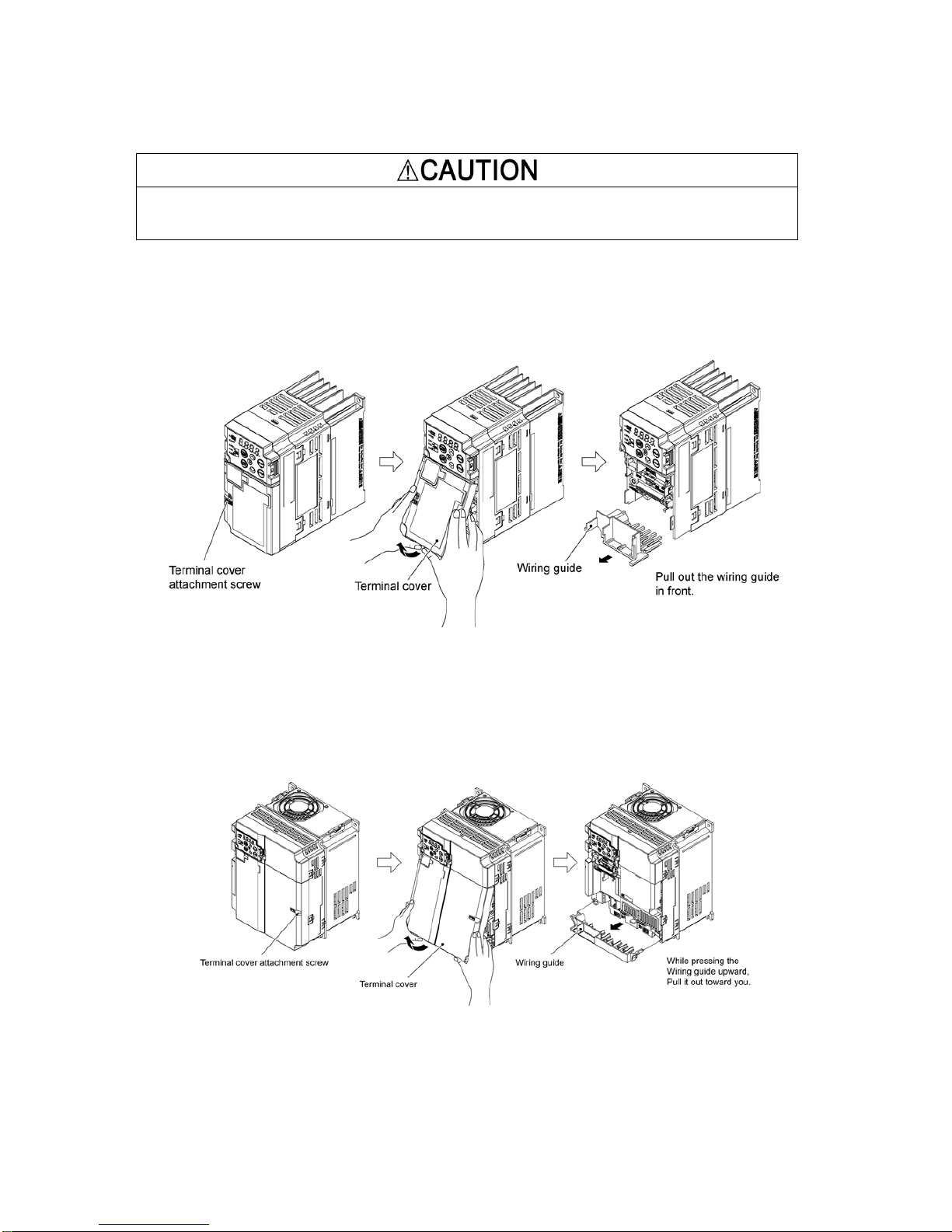
(1) Types FRN0020E2■-2/ FRN0012E2■-4/ FRN0011E2■-7 or below
1) Loosen the screws of the terminal cover. To remove the terminal cover, put your finger in the dimple of the
terminal cover and then pull it up toward you.
2) Pull out the wiring guide toward you.
3) After routing the wires, attach the wiring guide and the terminal cover reversing the steps above.
Figure 2.2-1 Removal of the Terminal Cover and the Wiring Guide (for FRN0006E2S-2)
(2) Types FRN0030E2■-2 to FRN0069E2■-2 and FRN0022E2■-4 to FRN0044 E2■-4
1) Loosen the screws of the terminal cover. To remove the terminal cover, put your finger in the dimple of the
terminal cover and then pull it up toward you.
2) Pull out the wiring guide toward you.
3) After routing the wires, attach the wiring guide and the terminal cover reversing the steps above.
Figure 2.2-2 Removal of the Terminal Cover and the Wiring Guide (for FRN0069E2■-2)
2-8
Page 19
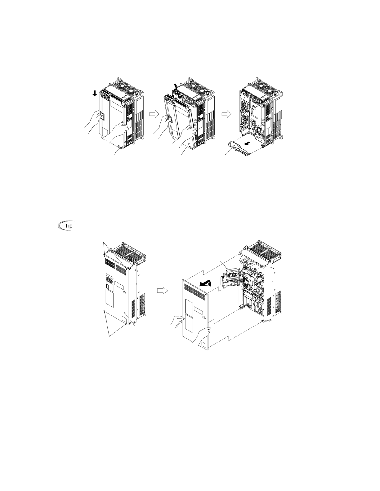
(3) Types FRN0088E2■-2/ FRN0115E2■-2/ FRN0072E2■-4/ FRN0085E2■-4
1) Loosen the screws of the front cover. Hold both sides of the front cover with the hands, slide the cover
downward, and pull. Then remove it to the upward dir ect ion.
2) Push the wiring guide upward and pull. Let the wiring guide slide and remov e it.
3) After routing the wires, attach the wiring guide and the front cover reversing the steps above.
Figure 2.2-3 Removal of the Front Cover and the Wiring Guide (for FRN0072E2■-4)
(4) Types FRN0085E2■-4 or above
1) Loosen the screws of the front cover. Hold both sides of the front cover with the hands and slide it upward to
remove.
2) After routing the wires, align the front cover top edge to the screw holes and attach the cover reversing the
steps in Figure 2.2-4.
Open the keypad case to view the control printed circuit board.
Tightening torque: 1.8 N·m(15.9 Ib-in) (M4)
3.5 N·m(31.0 Ib-in) (M5)
Figure 2.2-4 Removal of the front cover (for FRN0203E2■-4)
Screw
Screw
Front cover
Keypad case
Front
cover attachment screw
Front cover
Wiring guide
Push upward and pull.
Let the guide slide.
2-9
Page 20
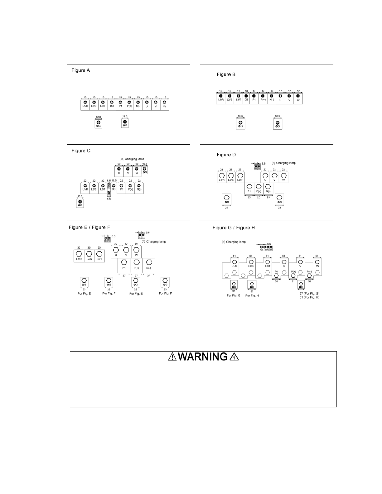
2.2.5 Main circuit terminals
Terminal layout diagram (main circuit terminals)
Figure 2.2-7 Main circuit terminals layout
The following terminals will have high voltage when power is ON.
Main circuit: L1/R, L2/S, L3/T, P1, P(+), N(-), DB, U, V, W, R0, T0, R1, T1
Insulation level
Main circuit - Casing : Basic insulation (overvoltage category III, degree of contamination 2)
Main circuit - Control circuit : Enhanced insulation (overvoltage category III, degree of contamination 2)
Risk of electric shock exists
For recommended wire sizes please refer to the User Manual.
2-10
Page 21
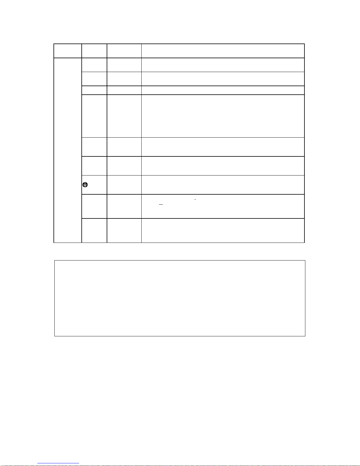
[ 1 ] Description of terminal functions (main circuit terminal)
Classification
Terminal
symbol
Terminal name Specification
Main circuit
L1/R, L2/S,
L3/T
Main power
input
Terminals to connect three-phase power source.
L1/L, L2/N
Main power
input
Terminals to connect single-phase power source.
U, V, W Inverter output Terminals to connect three-phase motors.
P (+), P1
For direct
current reactor
connection
Terminals to connect DC reactor (DCR) for power factor enhancement.
It must be connected in the following cases:
ND mode: Types FRN0139E2■-4G or above.
HD/HND mode: Types FRN0168E2■-4G or above.
HHD mode: Types FRN0203E2■-4G or above.
It is not required to connect a DC reactor when supplying the inverter only from PV
panel.
P (+), N (-)
For direct
current bus
connection
Terminals to connect to DC supply voltage from PV panel.
P (+), DB
For braking
resistor
connection
Terminals to connect a braking resistor (optional). Wiring length: Below 5 meters.
(Types FRN0220E2■-2G/FRN0072E2■-4G or below)
G
For inverter
chassis (case)
grounding
Grounding terminal for inverter chassis (case).
R0, T0
Auxiliary power
input for control
circuit
When it is desired to retain the alarm signal for the activation of the protective
function at even inverter main power supply sh
ut off or when continuous display of
the keypad is desired, connect this terminal to the power supply.
(Types FRN0185E2■-2G/FRN0059E2■-4G
or above)
R1, T1
Auxiliary power
input for fan
Ordinarily, these terminals do not need to be connected. Connect these terminals
to AC power supply when operating with direct current power input (such as in
combination with PWM converters).
(Types FRN0203E2■-4G or above)
Follow the sequence below when wiring.
(1) Inverter ground terminal (zG)
(2) Inverter output terminals (U, V, W), motor ground terminal (zG)
(3) Direct current reactor connection terminals (P1, P(+))*
(4) Braking resistor connection terminals (P(+), DB)*
(5) Direct current bus connection terminals (P(+), N(-))*
(6) Main power supply input terminals (L1/R, L2/S, L3/T) or (L1/L, L2/N)
*
Connect if necessary
2-11
Page 22
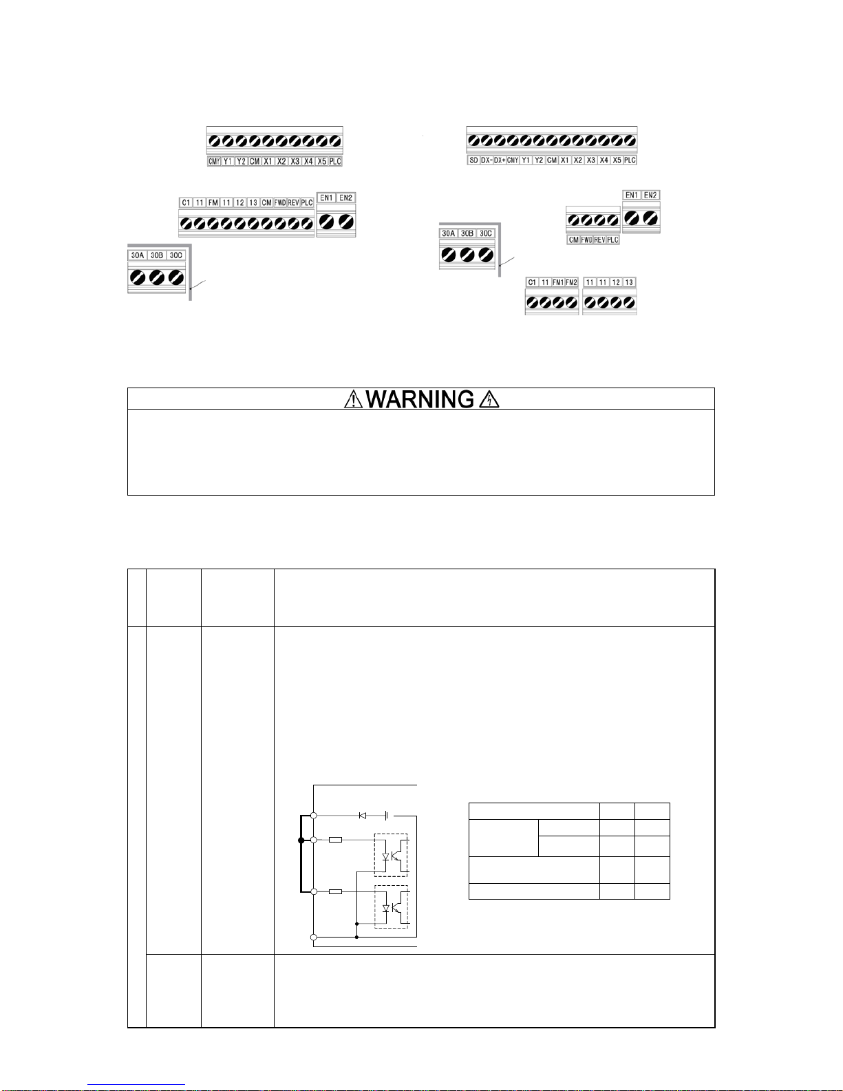
2.2.5 Control circuit terminals (common to all models)
[ 2 ] Terminal layout diagram (control circuit terminals)
FRNE2-A, E, K, U
FRNE2-C
Figure 2.2-8 Control circuit terminals layout
The following terminals will have high voltage when the power is ON.
Control terminals: AUX-contact (30A, 30B, 30C, Y5A, Y5C)
Insulation level
Contact output – control circuit : Enhanced insulation (overvoltage category II, degree of contamination 2)
Risk of electric shock exists
[ 3 ] Description of terminal functio ns ( control circuit terminal)
Table 2.2.6-3 Functional Description of Control Circuit Terminals (continued)
Classification
Terminal
symbol
Terminal name
Functional description
Digital input
[EN1]
[EN2]
Enable input
(1) When terminals [EN1]-[PLC] or terminals [EN2]-[PLC] are OFF, the inverter output
transistors stop functioning. (Safe Torque Off: STO)
Be sure to operate terminals [EN1] and [EN2] simultaneously; otherwise an ecf ala rm is
issued and the operation of the inverter will be disabled.
To enable the Enable function, remove the short bar.
(2) T he input mode for terminals [EN1] and [EN2] is fixed to source. The mode cannot be
switched to sink.
(3) Short-circuit terminals [EN1]-[PLC] and [EN2]-[PLC] with short bars when the Enable
input function is not used. (Keep the short bar connected).
<EN terminal circuit specification>
PLC
Photo coupler
CM
<Control circuit block>
6.6 kΩ
DC+24 V
EN1
6.6 kΩ
EN2
Shorting
bar
[PLC] Programma-
ble controller
signal power
source
(1) T he termi nal is used for c onnecting the output signal power source of the programm able
controller (rated voltage DC +24 V (power supply voltage fluctuation range: DC +22 to
+27 V) maximum 100 mA).
(2) The terminal can also be used for the power source for the load connected to the
transistor output. For details, refer to the page on transistor output.
Contact output
Enhanced insulation
(Max. 250 VAC overvoltage category II,
degree of contamination 2)
Contact output
Enhanced insulation
(Max. 250 VAC overvoltage category II,
degree of contamination 2)
Item Min. Max.
Operating
voltage
(SOURCE)
ON level 22 V 27 V
OFF level 0 V 2 V
Operating current at ON
(at input voltage 24 V)
- 4.5 mA
Allowable leak current at OFF - 0.5 mA
2-12
Page 23
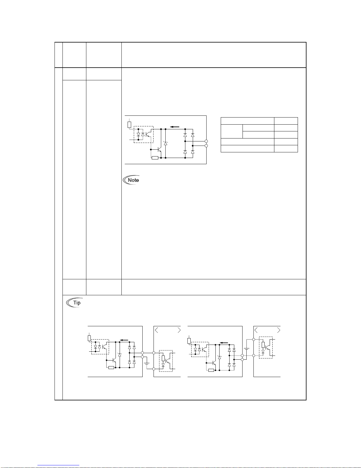
Table 2.2.6-3 Functional Description of Control Circuit Terminals (continued)
Classification
Terminal
symbol
Terminal name Functional description
Transistor output
[Y1] Transistor
output 1
(1) Various signals (running signal, frequency reached signal, overload forecast signal,
etc) set up by function code E20, E21 can be output. For details, refer to “Chapter 5
Function Codes”.
(2) The operating mode between transistor output terminals [Y1], [Y2] and terminal CMY
can be switched to “ON (active ON) at signal output” or “OFF (active OFF) at signal
output”.
<Transistor output circuit specification>
Photo coupler
<Control circuit block>
Y1 to
Y2
CMY
31 to 35V
Voltage
Current
Figure 2.2-14 Transistor Output Circuit
• Connect surge absorbing diode on both ends of the excitation coil when
c
onnecting control relays.
• When a power source is needed for the circuit to be connected, terminal PLC
can be used as a power source terminal (DC24 V (power supply volt
age
f
luctuation range: DC22 to 27 V), maximum 50 mA). In this case, terminal
[CMY] must be shorted to terminal [CM].
SW8 switches the [Y2] terminal output between a general-purpose output assigned by
function code E21 and a functional safety circuit failure output SRCF. The factory default
of SW8 is a general-purpose output.
When SRCF is assigned to terminal [Y2]:
if terminal [Y2] is ON, it means "No ecf alarm."
if terminal [Y2] is OFF, it means "ecf alarm has occurred."
Note that when SRCF is assigned, the operating mode between terminals [Y2] and [CMY]
is fixed at "active ON" (ON at signal output).
For details about an ecf alarm, refer to Section 6.3.2 "Causes, checks and measures of
alarms."
[Y2] Transistor
output 2
[CMY] Transistor
output common
This terminal is the common terminal for transistor output signals.
This terminal is insulated against terminals [CM] and [11].
When connecting the programmable controller to terminals [Y1], [Y2].
The circuit configuration example for connecting the inverter transistor output to the programmable controller
is shown in Figure 2.2
-15. Circuit (a) in Figure 2.2-15 shows the programmable controller input circuit as sink
input and circuit (b) shows as the source input case.
C0
DC+24 V
Programmable
controller
Sink type input
Photo coupler
<Control circuit block>
Y1,
Y2
CMY
31 to
35 V
Current
C0
Programmable
controller
Source type
input
DC+24 V
Photo coupler
<Control circuit block>
Y1 to
Y2
CMY
31 to
35 V
Current
(a) Connec tion diagram for sink input type
programmable controller
(b) Connection diagram for source input
type programmable controller
Figure 2.2-15 Example of Connection Circuit Configuration with Programmable Controller
Item Maximum
Operating
voltage
ON level
3 V
OFF level
27 V
Max load current at ON
50 mA
Leak current at OFF
0.1 mA
2-13
Page 24
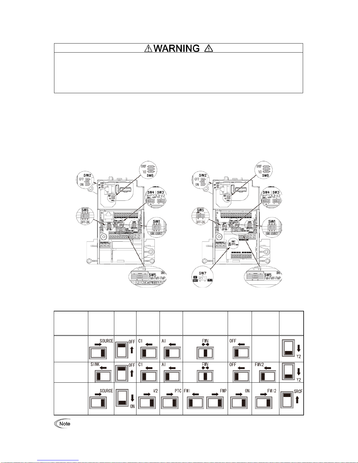
2.2.6 Operating slide switches
Operation of the various switches should be conducted after more than 5 minutes has elapsed since power
is shut off for types smaller than FRN0069E2
-2
and FRN0072E2-4 and after more than 10 minutes
has elapsed for types larger than FRN0085E2
-4
. Confirm that the LED monitor and the charge lamp are
turned off, and that the direct current intermediate circuit voltage between the main circuit terminals P(+) - N(-)
is below the safe voltage (below DC+25 V) with the tester before operating the switches.
Risk of electric shock exists.
The I/O terminal specification can be changed, such as switching the analog output form, by operating the various
slide switches on the printed circuit board (Figure 2.2-22 Slide Switches Positions on the Control Printed Circuit
Board).
To operate the various slide switches, remove the front cover and make the control printed circuit board visible.
(For types larger than FRN0085E2-4, also open the keypad case).
Refer to Section 2.2.2 "Removal and attachment of the front cover and wiring guide" to remove the front
cover and to open/close the keypad case.
The slide switches positions on the control printed circuit board are shown below.
FRNE2-A, E, K, U FRNE2-C
Figure 2.2-9 Slide Switches Locations on the Control Printed Circuit Board
SW1 SW2 SW3 SW4 SW5 SW6
SW7
only on
FRN
E2
-
C
SW8
Factory default
FRN
E2
-E
―
Factory default
FRN
E2
-A, C, K, U
―
Use pointed devices (such as tweezers) to operate the switches. Avoid touching other electronic parts
when moving the switches. The switch will be at open state when the slider is in the middle, so make
sure to push the slider to the ends.
2-14
Page 25

Functional description of the slide switches is given in Table 2.2.8-1 "Functional Description of Various Switches."
Table 2.2.8-1 Functional Description of Slide Switches
Switch
symbol
Functional description
SW1
<Switch to change sink/source setting of digital input terminals>
• This switch determines the type of input (sink or source) to use for digital input terminals [X1] to [X5],
FWD, and REV.
SW2
<Switch to change the RS-485 communication termi nating resist or (RS-485 communication port (on the
control PCB))>
• Move to the ON side when RS-485 communication is used and this inverter is connected to the
termination.
SW3
SW4
<Switch to change terminal [C1] input setting to current/voltage/PT C thermist or >
This switch changes the input type for terminal [C1].
Input type
SW3 SW4 E59 H26
Current input (factory default)
C1 side
AI side 0 0
Voltage input
V2 side
AI side 1 0
PTC thermistor input
C1 side
PTC side
0
1
SW5
<Switch to change terminal [FM] output setting to current/voltage/pulse>
This switch changes the output type for terminal [FM]. When operating this switch, also change function
code F29.
Output type
SW5 F29
Current output
FMI side
1 or 2
Voltage output (factory default)
FMV side 0 Pulse output
FMP side
3
SW6
<Switch to change the RS-485 communication terminating resistor (RS-485 c ommunicat i on port (on the
terminal board))>
FRNE2-A, E, K, U
• Used for the RS-485/CANopen communication. Move the switch to the ON position when the inverter is
connected to the terminal. They cannot be used simultaneously.
FRNE2-C
• Used for the RS-485 communication. Move the switch to the ON position when the inverter is connecte
d
t
o the termination.
SW7
<Switch to change terminal [FM2] output setting to voltage/current> The terminal is used only on the
FRNE2-C.
This switch changes the output type for terminal [FM2]. When operating this switch, also change function
code F32.
Output type
SW7 F32
Voltage output
FMV2 side
0
Current output
FMI2 side
1 or 2
SW8
<Switch to change terminal [FM2] output setting to general-purpose/SRCF >
This switch changes the output for terminal [Y2].
Output
SW8
General-purpose output
Y2 side
SRCF output
SRCF side
Exercise caution as expected operation may not result
if the setting above is not conducted accurately.
2-15
Page 26

2.3 Attachment and Connection of Keypad
2.3.1 Parts required for connection
The following parts are necessary when attaching the keypad to locations other than the inverter main body.
Part name Type Remarks
Keypad extension cable (note 1) CB-5S, CB-3S, CB-1S Three lengths available (5 m, 3 m, 1 m) (3.3ft, 9.8ft, 16.4ft)
Keypad fixing screws
M3x
(note 2)
2 screws required (prepared by user)
(Note 1) When using commercially avai labl e LAN cabl e, use 10BA SE-T/100BASE-TX straight cables (below 20
meters) which meet the ANSI/TIA/EIA-568A category 5 standards of U.S.A.
Recommended LAN cable
Manufacturer: Sanwa Supply, Inc.
Type: KB-10T5-01K (for 1 meter)
KB-STP-01K (for 1 meter) (shielded cable when conforming to EMC directive)
(Note 2) When attaching to the cabinet, use a fixing screw of appropriate length to the cabinet thickness.
2.3.2 Attachment procedure
The keypad can be attached in the following forms.
Attach to the inverter main body (refer to figure 2.3-1(a), (b), (c))
Attach to the cabinet (refer to figure 2.3-2)
Operate the panel remotely, on the hand (refer to Figure 2.3-3)
(a) FRN0069E2■-2G
(b) FRN0072E2■-4G
(c) FRN0203E2■-4G
Figure 2.3-1 Attaching the Keypad to the Inverter Main Body
Figure 2.3-2 Attaching the Keypad
on the Cabinet
Figure 2.3-3 Operating the Keypad Remotely,
on the Hand
Keypad
Keypad
Cabinet
Extension cable for
remote operation
Extension cable for
remote operation
Inverter main
body
Keypad
Keypad fixing
screws
Keypad
Inverter main
body
Keypad
2-16
Page 27

Attachment to the cabinet
(1) Squeeze the hooks at the arrows and pull as shown in the figure below.
Figure 2.3-4 Removal of the Keypad
(2) Attach the keypad rear cover to the keypad using the included keypad rear cover fixing screw.
Figure 2.3-5 Attachment of the Keypad
Keypad rear cover fixing
screw
Keypad rear cover
Keypad
2-17
Page 28

(3) Cut the cabinet to attach the keypad, as shown in figure 2.3-6
(Units: mm [inch])
Figure 2.3-6 Fixing Screw Positions and the Dimensions of the Cabinet to Cut
2-18
Page 29

(4) Fix the keypad to the cabinet using 2 keypad rear cov er fixing screws. Refer to figure 2.3-7 (tightening torque:
0.7 N•m(6.2lb-in)).
Figure 2.3-7 Attachment of the Keypad
(5) Connect the extended cable for remote operation (CB-5S, CB-3S, CB-1S) or the commercially available LAN
cable (straight) to the keypad RJ-45 connector and the inverter main body RJ-45 connector (modular jack).
Refer to Figure 2.3-8.
Figure 2.3-8 Connection of the Extension Cable or the Commercially Available LAN Cable between the Keypad
and the Inverter Main Body
• The RJ-45 connector for keypad connection is specializ ed fo r keypad communication and does not support
RS-485 communication. Connection with the PC loader is not possible.
• Do not connect the inverter to PC LAN ports, Ethernet hubs, or tel ephone lines. The inverter and the
connected instrument may be damaged.
Risk of fire and risk of accidents exist.
Operating remotely, on the hand
Connect following the procedure (5) in “Attachment to the cabinet”.
Cabinet
Keypad fixing
screws
Cabinet
Keypad
RJ-45 connector
RJ-45 connector
(modular jack)
Connect to the RJ-45
connector of
the
inverter main body
Extended cable for remote
operation (CS
-5S, CB-3S,
CB
-1S) or LAN cable
2-19
Page 30

2.4 RJ-45 Cover
The opening for the RS-485 communi cat ion cab le con nec tion (RJ-45 connector) is located below the keypad, as
shown in figure 2.4-1(a), (b).
Types FRN0069E2■-2G / FRN0044E2■-4G or below
To connect the RS-485 communication cable, open the RJ-45 cover as shown in the figure below.
Figure 2.4-1 (a) Connection of the RS-485 Communication Cable
Types FRN0185E2■-2G / FRN0059E2■-4G or above
To connect the RS-485 communication cable, open the RJ-45 cover until the “click” can be heard and connect the
cable as shown in the figure below.
Figure 2.4-1 (b) Connection of the RS-485 Communication Cable
Connect with the PC via the RS-485 converter using the RS-485 communication cable. The PC loader allows
editing, confirmation, and management of the inverter function codes, and monitoring of operation data remotely.
The operating status and alarms can also be monitor ed.
RJ-45 cover
RJ-45 cover
2-20
Page 31

3-1
Chapter 3 OPERATION USING THE KEYPAD
3.1 Names and Functions of Keypad Components
The keypad allows you to run and stop the motor, display various data, configure function code data, and
monitor I/O signal states, maintenance information and alarm information.
Table 3.1-1 Overview of Keypad Functions
Item
LED Monitor,
Keys, and
LED Indicators
Functions
LED Monitor
Four-digit, 7-segment LED monitor which displays the followings according to the
operation modes.
In Running mode: Running status information (e.g., output frequency,
current, and voltage)
When a light alarm occurs,
l-al
is displayed.
In Programming mode: Menus, function codes and their data
In Alarm mode: Alarm code, which identifies the alarm factor that has
activated the protective function.
Operation
Keys
P
rogram/Reset key which switches the operation modes of the inverter.
In Running mode: Pressing this key switches the inverter to Programming
mode.
In Programming mode: Pressing this key switches the inverter to Running mode.
In Alarm mode: Pressing this key after removing the alarm factor resets
the alarm and switches back to Running mode.
Function/Data key which switches the operations you want to do in each mode as
follows:
In Running mode: Pressing this key switches the information to be
displayed concerning the status of the inverter (output
frequency (Hz), output current (A), output voltage (V),
etc.).
When a light alarm is displayed, holding down this key
resets the light alarm and switches back to Running
mode.
In Programming mode: Pressing this key displays the function code or
establishes the data entered with and keys.
In Alarm mode: Pressing this key displays the details of the problem
indicated by the alarm code that has come up on the
LED monitor.
RUN key. Press this key to run the motor.
STOP key. Press this key to stop the motor.
and
UP and DOWN keys. Press these keys to select the setting items and change the
function code data displayed on the LED monitor.
Shift key. Press this key to shift the cursor to the right for entry of a numerical value.
LED indicators
DOWN key
STOP key
UP key
Function/Data
key
RUN key
7-segment
LED monitor
Program/Reset key
RUN LED
Shift key
Page 32

3-2
Table 3.1-1 Overview of Keypad Functions (continued)
Item
LED Monitor,
Keys, and
LED Indicators
Functions
LED
Indicators
RUN LED
Lights when running with a run command entered by the
key, by terminal
command FWD or REV, or through the communications link.
KEYPAD
CONTROL LED
Lights when the inverter is ready to run with a run command entered by the key
(F02 = 0, 2, or 3). In Programming and Alarm modes, however, pressing the key
cannot run the inverter even if this indicator lights.
Unit LEDs
(3 LEDs)
These three LED indicators identify the unit of numeral displayed on the LED monitor in
Running mode by combination of lit and unlit states of them.
Unit: Hz, A, kW, r/min and m/min
Refer to Section ¡Error! No se encuentra el origen de la referencia. "¡Error! No se
encuentra el origen de la referencia." for details.
While the inverter is in Programming mode, Hz
the LEDs of Hz and kW light. A
kW
x10 LED
Lights when the data to display exceeds 9999. When this LED lights, the "displayed
value x 10" is the actual value.
Example:
If data is "12,345," the LED monitor displays
1234
and the x10 LED lights, meaning
that "1,234 × 10 = 12,340."
LED monitor
In Running mode, the LED monitor displays running status information (output frequency, current or
voltage); in Programming mode, it displays menus, function codes and their data; and in Alarm mode, it
displays an alarm code which identifies the alarm factor that has activated the protective function.
If one of LED4 through LED1 is blinking, it means that the cursor is at this digit, allowing you to change it.
If the decimal point of LED1 is blinking, it means that the currently displayed data is a value of the PID
command, not the frequency data usually displayed.
Figure 3.1-1 7-Segment LED Monitor
Table 3.1-2 Alphanumeric Characters on the LED Monitor
Character 7-segment Character 7-segment Character 7-segment Character 7-segment
0
0000
9
9999
i
IIII
r
rrrr
1
1111
A
aaaa
J
JJJJ
S
ssss
2
2222
b
Bb
BbBb
Bb
K
KKKK
T
TTTT
3
3333
C
Cc
CcCc
Cc
L
llll
u
UUUU
4
4444
d
dddd
M
mmmm
V
uuuu
5
5555
E
eeee
n
nnnn
W
wwww
6
6666
F
ffff
o
oooo
X
xxxx
7
7777
G
gggg
P
pppp
y
yyyy
8
8888
H
hhhh
q
qqqq
Z
ZZZZ
Special characters and symbols (numbers with decimal point, minus and underscore)
0. - 9.
*
* *
* – ))))
-
-
_
_
Page 33

3-3
3.2 Overview of Operation Modes
The FRENIC-Ace features the following three operation modes.
Table 3.2-1 Operation Modes
Operation mode
Description
Running mode
When powered ON, the inverter automatically enters this mode.
This mode allows you to specify the reference frequency, PID command value and etc., and
run/stop the motor with the / keys.
It is also possible to monitor the running status in real time.
If a light alarm occurs, the
l-al
appears on the LED monitor.
Programming
mode
This mode allows you to configure function code data and check a variety of information
relating to the inverter status and maintenance.
Alarm mode
If an alarm condition arises, the inverter automatically enters Alarm mode in which you can
view the corresponding alarm code* and its related information on the LED monitor.
* Alarm code: Indicates the cause of the alarm condition. For details, first see Table 6.1
"Abnormal States Detectable ("Heavy Alarm" and "Light Alarm" Objects)" in Chapter 6,
Section 6.1 "Protective Function," and then read the troubleshooting of each alarm.
Figure 3.2-1 shows the status transition of the inverter between these three operation modes.
Programming mode
Configuration of function
code data and monitor of
maintenance/alarm info
and various status
Alarm mode
Display of alarm status
Occurrence of
a heavy alarm
(Press this key if
an alarm has
occurred.)
+
Running mode
Release of
a light alarm
Monitor of running status
Light alarm displayed
Run/Stop of motor
Run/Stop of motor
Detection of
a light alarm
Power ON
Release of
a heavy alarm
Figure 3.2-1 Status Transition between Operation Modes
Simultaneous keying
Simultaneous keying means pressing two keys at the same time. The simultaneous keying operation is
expressed by a "+" letter between the keys throughout this manual.
For example, the expression " + keys" stands for pressing the key with the key held down.
Page 34

3-4
Figure 3.2-2 illustrates the transition of the LED monitor screen during Running mode, the transition between menu
items in Programming mode, and the transition between alarm codes at different occurrences in Alarm mode.
(*1) The speed monitor allows you to select the desired one from the speed monitor items by using function code
E48.
(*2) Applicable only when PID control is active (J01 = 1, 2 or 3).
(*3) The analog input monitor can appear only when the analog input monitor function is assigned to one of the
analog input terminals by one of function codes E61 to E63 (= 20).
(*4)
0
appears under the V/f control.
(*5) The Timer screen appears only when the timer operation is enabled with function code C21 (C21 = 1).
(*6) Applicable only when the full-menu mode is selected (E52 = 2).
Figure 3.2-2 Transition between Basic Screens in Individual Operation Mode
Page 35

4-1
Chapter 4 SET UP PROCEDURE
This chapter describes a simple step by step set up procedure of FRENIC-Ace for solar pumping application.
Please refer to:
- chapter 2 for detailed information about installation and wiring
- chapter 3 for the information about the operation of the keypad
- chapter 5 for detailed description of the function codes.
In order to set up FRENIC-Ace for solar pumping application, please proceed with the following step by step
procedure:
1. Install the inverter as described in chapter 2 of this manual.
2. Set up the motor parameters and, whenever possible, execute the auto tuning procedure. If the
motor is already coupled with the load (pump) please execute static auto-tuning (P04=1). If the
motor can be dismounted from the load please execute dynamic auto-tuning (P04=2), which
measures more motor parameters than the static auto-tuning (for details, please refer to chapter 5).
Some functions like the dry pump detection and low power detection will work with the best
accuracy only if the motor parameters are correctly set.
3. Set up the parameter F02 (Operation method) to 1 (External signal).
4. Set up the parameter H11 (Deceleration mode) to 1 (Coast to a stop).
5. Set the PID control related parameters:
o J01 (Mode selection) to 2 (inverse operation)
o J02 (Remote command) to 1 (PID process command 1)
o J06 (Feedback filter) to 0.0s (No filter).
6. Set up the following parameters related to the PV panel specifications:
o Function code U126 (PV panel open circuit voltage) is used to set the PV panel open circuit
voltage
o Function code U127 (PV panel MPP voltage) is used to set the PV panel MPP voltage
7. Set up the following parameters related to the MPP search (tracking) function:
o Function code U121 (Enable MPP search) must be set to “1.00” to enable the MPP search
function
o Function code U135 (Voltage/PID set point increase/decrease step for MPP search) to set the
set point increase/decrease at each step of the MPP search function.
8. Set up the parameters related to the sleep function:
o Function code J15 (Sleep frequency) to set the minimum frequency level to keep running,
because the pump is not anymore effective when rotating at lower speeds than the value set in
this function code. This setting depends mainly on the pump specifications.
o Function code U134 (Power level to keep running) to set the minimum power level to keep
running. If the power level is very small, it means that the pump may not be effective anymore.
This setting depends mainly on the pump specifications.
It is important to note that it is not compulsory to set both parameters. The inverter can use either the
sleep frequency or the minimum power as the stop (sleep) criteria. In other words, it is not required to
fulfill both conditions.
Do not change the value of function code J17 from factory default value, otherwise it would interfere
with the sleep and wake up functions.
9. Set up the following parameters related to the wake up function:
o Function code U131 (DC link voltage level to start) to set the minimum voltage level of the PV
panel (DC link) to allow the operation of the inverter. This parameter is very important to avoid
that the inverter (pump) starts operation when there is not enough available power from the PV
panel. The value of this parameter can be set from PV panel specification or from tests at very
low irradiance conditions (for example during sunset).
Do not change the value of function code J17 from factory default value, otherwise it would interfere
with the sleep and wake up functions.
Page 36

4-2
10. Set up the initial parameters of the PID regulator:
o PID controller gains J59 (P Gain 2) and J60 (I integral time 2), used when the PID feedback
value is higher than the PID set point value. As initial values set the values recommended in
chapter 5.
o PID controller gains U132 (P Gain 1) and U133 (I integral time 1), used when the PID feedback
value is lower than the PID set point value. As initial values set the values recommended in
chapter 5.
11. Check that the function codes related to the digital inputs [FWD] and [REV] are set to “No function
assigned”.
( Function code E98, E99 data = 100)
12. If tank high level digital detection signal is used, check that the function code related to the digital
input [X1] is set to “No function assigned”.
( Function code E01 data = 100)
13. If tank level analog detection signal is used, set function code U128 (High level) to the desired
maximum level of the tank. If this signal is not used, set function code U128 to 100%, to ensure that
the pump starts (inverter operates) regardless of the value on the analog input of the inverter.
14. Ensure that function code U00 (Mode Selection) is set to 1, in order to enable the Solar Pumping
application.
• When setting U00 to 1 the operation of the inverter may start (if all necessary conditions are fulfilled).
Please ensure that it is safe to start operation.
An accident or physical injury may result.
Page 37

5-1
Chapter 5 FUNCTION CODES
This chapter describes the function codes used to set FRENIC-Ace for Solar Pumping application.
5.1 Function Codes Table
The table below describes the function codes used to set up FRENIC Ace inverter for Solar Pumping application.
For other function codes not described in this manual refer to FRENIC Ace User’s Manual. In case of using PMS
motor please refer to the FRENIC Ace User’s Manual for the correct setting of motor parameters.
Code Keypad code Name Data setting range
Factory
default
Setting
F02 F02 Operation method
0: Keypad operation (rotation direction input:
terminal block)
1: External signal (digital input)
2: Keypad operation (forward rotation)
3: Keypad operation (Reverse rotation)
2 1
F03 F03 Maximum output frequency 1 25.0 to 500.0 Hz
200V class
AJKU:60.0
400V class
ACE:50.0
JKU:60.0
App.
(Note 1)
F04 F04 Base frequency 1 25.0 to 500.0Hz
200V class
J:50.0
AUK:60.0
400V class
ACEJ:50.0
UK:60.0
App.
(Note 1)
F05 F05 Rated voltage at base frequency 1
0: AVR disable (output voltage proportional to
power voltage)
80 to 240 V: AVR operation (200V class)
160 to 500V: AVR operation (400V class)
App.
(Note 1)
F06 F06 Maximum output voltage 1
80 to 240V: AVR operation ( 200V class)
160 to 500V: AVR operation ( 400V class)
App.
(Note 1)
F07 F07 Acceleration time1 6.00
F08 F08 Deceleration time1 0.50
F09 F09 Torque boost 1
0.0 to 20.0% (% value against base frequency
voltage 1)
(Note 7)
App.
(Note 1)
F10 F10
Electronic thermal overload
protection for motor 1 (Select motor
characteristics)
1: Enable (For a general-purpose motor with selfcooling fan)
2: Enable (For an inverter-driven motor (FV) with
separately powered cooling fan)
1
App.
(Note 1)
F11 F11
Electronic thermal overload
protection for motor 1 (Overload
detection level)
0.00 (disable), current value of 1 to 135% of
inverter rated current
(Inverter rated current dependent on F80)
(Note 3)
App.
(Note 1)
F12 F12
Electronic thermal overload
protection for motor 1 (Thermal time
constant)
0.5 to 75.0 min (Note 4)
App.
(Note 1)
F37 F37
Load selection/
Auto torque boost/
Auto energy-saving operation 1
0: Variable torque load
1: Constant torque load
2: Auto torque boost
3: Auto energy-saving operation (variable torque
load)
4: Auto energy-saving operation (constant
torque load)
5: Auto energy-saving operation with auto torque
boost
1
App.
(Note 1)
F42 F42 Drive control selection 1
0: V/f control without slip compensation
1: Vector control without speed sensor (dynamic
torque vector)
2: V/f control with slip compensation
3: V/f control with speed sensor
4: V/f control with speed sensor and auto torque
boost
6: Vector control for induction motor with speed
sensor
15: Vector control for synchronous motor without
speed sensor nor pole position sensor
0 (Note 5)
200V class
J:200
AK:220
U:230
400V class
EJ:400
A:415
CK:380
U:460
0.00 to 6000 s
6.00 or
20.0
Page 38

5-2
Code Keypad code Name Data setting range
Factory
default
Setting
F80 F80
Switching between ND,HD,HND and
HHD drive modes
0: HHD mode
1: HND mode
3: HD mode
4: ND mode
ND/HD mode is not supported for 200V class
series.
4 (Note 6)
E01 E01 Terminal [X1] function 0 100
E98 E98 Terminal [FWD] function 98 100
E99 E99 Terminal [FWD] function 99 100
E20 E20 Terminal [Y1] function 0 111
E21 E21 Terminal [Y2] function 7 112
E27 E27 Terminal [30A/B/C] function 99 99
P01 P01
Motor 1 (No. of poles) 2 to 22 poles 4
App.
(Note 1)
P02 P02
Motor 1 (Rated capacity)
0.01 to 1000 kW (At P99 = 0 or 4, 15)
0.01 to 1000 HP (At P99 = 1)
(Note 7)
App.
(Note 1)
P03 P03
Motor 1 (Rated current) 0.00 to 2000A (Note 7)
App.
(Note 1)
P04 P04
Motor 1 (Auto tuning)
0: Disable
1: Stop tuning
2: Rotation tuning
5: Stop tuning (%R1, %X)
0 -
P06 P06
Motor 1 (No-load current) 0.00 to 2000A (Note 7)
App.
(Note 1)
P07 P07
Motor 1 (%R1) 0.00 to 50.00% (Note 7)
App.
(Note 1)
P08 P08
Motor 1 (%X) 0.00 to 50.00% (Note 7)
App.
(Note 1)
P12 P12
Motor 1 (Rated slip frequency) 0.00 to 15.00 Hz (Note 7)
App.
(Note 1)
H03 H03
Data initialization
0: Manual setting value
1: Initial value (factory default value)
2: Initialize motor 1 parameters
3: Initialize motor 2 parameters
11: Initialize the parameters(excluding
parameters related to communication)
12: Initialize the parameters related to
customizable logic
0 -
H06 H06
Cooling fan ON/OFF control
0: Disable (Always Fan ON)
1: Enable (ON/OFF control effective)
0 0
H11 H11
Deceleration mode 0: Normal deceleration
1: Coast to a stop
0 1
H50 H50
Non-linear V/f 1 (Frequency) 0.0 (Cancel), 0.1 to 500.0 Hz 0.0
App.
(Note 1)
H51 H51
Non-linear V/f 1 (Voltage)
0 to 240 V: AVR operation ( 200 V class)
0 to 500V: AVR operation ( 400V class)
0
App.
(Note 1)
H52 H52
Non-linear V/f 2 (Frequency) 0.0 (Cancel), 0.1 to 500.0 Hz 0.0
App.
(Note 1)
H53 H53
Non-linear V/f 2 (Voltage)
0 to 240 V: AVR operation ( 200 V class)
0 to 500V: AVR operation ( 400V class)
0
App.
(Note 1)
H72 H72
Main power shutdown detection (Mode
selection)
0: Disables main circuit power cutoff detection
0: Enables main circuit power cutoff detection
(Only for )
1 0
H111 H111
UPS operation level
150 to 220 VDC: (200 V class)
240 to 440 VDC: (400 V class)
220
440
150
240
J01 J01
PID control (Mode selection)
0: Disable
1: Process (normal operation)
2: Process (inverse operation)
3: Speed control (Dancer)
0 2
J02 J02
PID control (Remote command)
0: Keypad key operation ( / key)
1: PID process command 1 (Analog input:
Terminals 12, C1 and V2)
3: UP/DOWN
4: Communication
0 1
J06 J06 PID control (Feedback filter) 0.0 to 900.0 s 0.5 0.0
J59 J59
PID control P (Gain) 2 0.000 to 30.000 times 0.100
1.2
(Note 1)
J60 J60
PID control I (Integral time) 2 0.0 to 3600.0 s 0.0
1.0
(Note 1)
Refer to User Manual
Refer to User Manual
Page 39

5-3
Code Keypad code Name Data setting range
Factory
default
Setting
U132 U132
PID gains switching (P gain 1 for fast
reaction, Feedback < Set point)
0.00 to 30.00 times 0.00
1.4
(Note 1)
U133 U133
PID gains switching (I Integral time 1 for
fast reaction, Feedback < Set point)
0.0 to 3600.0 s 0.00
0.3
(Note 1)
y20 y20
RS-485 Communication 2 (Protocol
selection)
0: Modbus RTU protocol
1: FRENIC Loader protocol (SX protocol)
2: Fuji general-purpose inverter protocol
0
App.
(Note 1)
U128 U128 Tank level detection function (High level) 0.00 to 100.0%
100%: Maximum detection level
0.00 100.0
UA14 U15
Tank level detection function (High level
hysteresis width)
0.00 to 100.0%
100%: Maximum detection level
5 5
UA18 U19
Tank level detection function (Signal ON
Delay Time)
0.00 to 60 s 15 15
UA23 U24
Tank level detection function (Signal
OFF Delay Time)
0.00 to 60 s 15 15
U130 U130
Low power detection function (Low
Power level)
0.00 to 100.0%
100%: Motor rated power (P02)
0.00
App.
(Note 1)
UA48 U49
Low power detection function (Signal ON
Delay Time)
0.00 to 60 s 15 15
UA53 U54
Dry pump detection function (Output
frequency level)
0.00 to 100.0%
100%: Maximum frequency (F03)
80 80
UA54 U55
Dry pump detection function (Output
frequency hysteresis width)
0.00 to 100.0%
100%: Maximum frequency (F03)
5 5
UA68 U69
Dry pump detection function (Motor
power level)
0.00 to 100.0%
100%: Motor rated power (P02)
30 30
UA69 U70
Dry pump detection function (Motor
power hysteresis width)
0.00 to 100.0%
100%: Motor rated power (P02)
5 5
UA73 U194 (U190=15)
Dry pump detection function (Signal ON
Delay Time)
0.00 to 60 s 15 15
U124 U124
Dry pump detection function (Enable Dry
Pump Alarm)
0.00: Disable dry pump alarm (OH2)
1.00: Enable dry pump alarm (OH2)
0.00 0.00
U126 U126
PV panel specifications (PV panel open
circuit voltage)
0.00 to 1000 V 0.00
App.
(Note 1)
U127 U127
PV panel specifications (PV panel MPP
voltage)
0.00 to 1000 V 0.00
App.
(Note 1)
U172 U172
Measurement at open circuit voltage
condition (affected by multiplication
factor U127/U126)
0.00 to 100.0%
100%=500V (-2/-7), 1000V (-4)
- -
U121 U121 MPP search (Enable MPP search)
0.00: Disable MPP search
1.00: Enable MPP search
0.00 1.00
U123 U123
MPP search (Enable manual setting of
PV panel voltage set point)
0.00: Disable manual setting of U171
1.00: Enable manual setting of U171
0.00 0.00
U171 U171
MPP search (Actual PV panel voltage
set point)
0.00 to 100.0%
100%=500V (-2/-7), 1000V (-4)
0.00
App.
(Note 1)
U135 U135
MPP search (Voltage/PID set point
increase/decrease step for MPP search)
0.00 to 100.0%
100%=500V (-2/-7), 1000V (-4)
0.00 0.20
UB88 U194 (U190=38) MPP search (Time interval) 0.01 to 1.00 0.02 0.02
J15 J15
Sleep function (Sleep frequency) 0.0 (Disable): 1.0 to 500.0 Hz 0.0
App.
(Note 1)
U134 U134
Sleep function (Power level to keep
Running)
0.00 to 100.0%
100%: Motor rated power (P02)
0.00 25.0
UD88 U194 (U190=78) Sleep function (Sleep time) 0.00 to 60 s (recommended range) 40 40
U131 U131
Wake up function (DC link voltage level
to start)
0.00 to 500 V: (200V class)
0.00 to 1000 V: (400V class)
0.00 250
500
UD98 U194 (U190=80) Wake up function (time) 0.00 to 180 s (recommended range) 60 60
U125 U125 Big step detection (Disable) 0.00: Enable big step
1.00: Disable big step
0.00 0.00
UI08 U194 (U190=162)
Big step detection (Dead time for next
action)
0.00 to 20.0 s (recommended range) 6.00 6.00
UH18 U194 (U190=144)
Big step UP detection (Level to detect
big step UP)
0.00 to 100.0%
100%=500V (-2/-7), 1000V (-4)
3 3
UH48 U194 (U190=150)
Big step UP detection (Time to follow the
step UP change)
0.00 to 4.0 s (recommended range) 1.0 1.0
Page 40

5-4
Code Keypad code Name Data setting range
Factory
default
Setting
UH53 U194 (U190=151)
Big step DOWN detection (Level to
detect big step DOWN)
0.00 to 100.0%
100%=500V (-2/-7), 1000V (-4)
3 3
UH83 U194 (U190=157)
Big step DOWN detection (Time delay to
follow the step DOWN)
0.00 to 10.0 s (recommended range) 4.0 4.0
UH88 U194 (U190=158)
Big step DOWN detection (Time to
follow the step DOWN change)
0.00 to 4.0 s (recommended range) 1.0 1.0
U00 U00
Customizable logic
(Mode selection)
0: Disable
1: Enable (Customizable logic operation)
ECL alarm occurs when the value is changed
from 1 to 0 during operation.
0 1
(Note 7): Depends on motor capacity
(Note 1): Depends on the application
(Note 2): Please set U190 to the number inside the brackets prior to changing this function
(Note 3): The motor rated current is automatically set. Refer to Table B (function code P03)
(Note 4): 5.0min for inverters of nominal applied motor 22kW or below; 10.0min for those of 30kW or above
(Note 5): For solar pumping application recommended setting is 0 or 1
(Note 6): For solar pumping application recommended modes are HND or HHD
5.2 Description of Function Codes
This section describes details of function codes relevant for Solar Pumping application.
F02
Operation method
Related function codes: Terminal E98 [FWD] function
Terminal E99 [REV] function
F02 is used to select the method how run command is provided to the inverter. In case of Solar pumping
application please set F02 to 1, so that the operation command can be given from Customized Logic program.
Digital input signal, "FWD", "REV" should not be assigned to terminals [FWD], [REV], therefore please assign the
function of these terminals to “No function”.
( Function code E98, E99 data = 100)
• F02 cannot be changed when "FWD" or "REV" is ON.
F03
Maximum frequency 1
F03 specifies the maximum frequency that the inverter outputs. When the device to be driven is set to rated or
higher, the device may be damaged. Make sure to make an adjustment according to the design of the machinery.
• Data setting range: 25.0 to 500.0 (Hz)
Modes
Control mode
Data setting range
Remarks
HD/HND/HHD mode
V/f control
500 Hz
ND mode
V/f control
120 Hz
Restricted internally.*
* When setting is performed by exceeding the maximum setting range (for example, 500 Hz), speed setting and
analog output (FMA) become input/output mode of full scale/setting value (10V/ 500Hz). However, it is internally
restricted (for example, 120Hz), therefore, even if 10V is input for setting value, the value is restricted internally
by 2.4 V (equivalent to 120 Hz), not by 500Hz.
Use function code F80 to switch between ND, HD, HND and HHD drive modes.
Inverter can perform setting of high speed operation easily. When changing the setting, make sure to check the
motor and machine mode before use.
Injuries could occur. Failure may occur.
When changing maximum output frequency (F03), in order to make the operation frequency a larger
value, change the frequency limiter (upper limit) (F15) as well.
Page 41

5-5
F04, F05
F06
Base frequency 1, Rated voltage at base frequency 1
Maximum output voltage 1
Related function codes H50, H51 Non-linear V/f 1 (Frequency, voltage)
H52, H53 Non-linear V/f 2 (Frequency, voltage)
H65, H66 Non-linear V/f 3 (Frequency, voltage)
Set the base frequency and base frequency voltage that are essential to operation of the motor. By combining
related function codes H50 to H53, H65, and H66, it is possible to set non-linear V/f pattern (weak or strong voltage
by arbitrary point) and perform setting of V/f characteristics that is suitable for the load.
Impedance of the motor becomes larger with high frequency, and when output voltage becomes less, output torque
may be reduced. In order to prevent this, increase the voltage at high frequency by setting function code F06
(maximum output voltage 1). However, it is not possible to output voltage at or higher than the input power voltage
of the inverter.
Point of V/f
Function code
Remarks
Frequency
Voltage
Maximum output
frequency
F03
F06
During auto torque boost, vector control without speed
sensor, the maximum output voltage setting is disabled.
Base frequency
F04
F05
Non-linear V/f 3
H65
H66
This code is disabled during auto torque boost, vector
control without speed sensor.
Non-linear V/f 2
H52
H53
Non-linear V/f 1
H50
H51
<Setting example>
Normal V/f pattern setting
Non-linear V/f pattern setting (3 points)
Output voltage (V)
Maximum output voltage
Rated voltage at base frequency
Base frequency
Maximum output frequency 1
Output
frequency
Output voltage (V)
Maximum output voltage
Rated voltage at base frequency
Non-linear V/f pattern 3 (voltage)
Non-linear V/f pattern 2 (voltage)
Non-linear V/f pattern 1 (voltage)
Non-linear V/f
pattern 1
(frequency)
Non-linear
V/f pattern 2
(frequency)
Non-linear
V/f pattern
3 (frequency)
Base
frequency 1
Maximum
Output
frequency
Page 42

5-6
Base frequency (F04)
Set the data in accordance with rated frequency of the motor (given on the nameplate of the motor).
• Data setting range: 25.0 to 500.0 (Hz) (limited to 120 Hz (max.) in ND mode)
Rated voltage at base frequency (F05)
Set the data to “0” or in accordance with rated voltage of the motor (given on the nameplate of the motor).
• Data setting range: 0 : AVR disable
80 to 240 (V) : AVR operation (at 200 V class)
160 to 500 (V) : AVR operation (at 400 V class)
• When data is set to "0", the base frequency voltage becomes equivalent to inverter input voltage. When input
voltage fluctuates, output voltage fluctuates as well.
• When data is set to arbitrary voltage other than "0", automatically keeps the output voltage constant. When
control function such as auto torque boost, auto energy-saving operation, and skip compensation is used, it is
necessary to adjust to the rated voltage (given on the nameplate of the motor) of the motor.
The voltage that the inverter can output is lower than the input voltage of the inverter. Appropriately set
the voltage in accordance with the motor.
Non-linear V/f 1, 2, 3 (Frequency) (H50, H52, H65)
Set frequency at the arbitrary point of non-linear V/f pattern.
• Data setting range: 0.0 (Cancel), 0.1 to 500.00 (Hz)
When 0.0 is set, the setting becomes the pattern without using non-linear V/f pattern.
(limited to 120 Hz (max.) in ND mode)
Non-linear V/f 1, 2, 3 (Voltage) (H51, H53, H66)
Set voltage at the arbitrary point of non-linear V/f pattern.
• Data setting range: 0 to 240 (V) : AVR operation (at 200 V class)
0 to 500 (V) : AVR operation (at 400 V class)
Maximum output voltage 1 (F06)
Set the voltage at maximum output frequency 1 (F03).
• Data setting range: 80 to 240 (V) : AVR operation (at 200 V class)
160 to 500 (V) : AVR operation (at 400V class)
When rated voltage at base frequency (F05) is "0", the data of non-linear V/f (H50 to H53, H65, and H66)
and F06 becomes invalid (linear V/f for at or below base frequency, and constant voltage for at or higher
than base frequency).
Page 43

5-7
F07, F08
Acceleration time1, Deceleration time1 (Refer to F37)
Acceleration time sets the time taken by the output frequency to reach the maximum output frequency from 0Hz,
and deceleration time sets the time taken by the output frequency to reach 0Hz from the maximum frequency.
• Data setting range: 0.00 to 6000 (s)
For V/f control
F09
Torque boost 1 (Refer to F37)
For details of torque boost 1 setting, refer to the section of function code F37.
F10 to F12
Electronic thermal overload Protection for motor 1 (Select motor characteristics,
Thermal time constant)
In order to detect overload of motor (electronic thermal function by inverter output current), set temperature
characteristics of motor: Select motor characteristics (F10), thermal time constant (F12), and overload detection
level (F11).
When overload of motor is detected, inverter is turned off, protecting the motor with motor overload alarm 0l1.
Improper setting of the electronic thermal function may result in a failure to protect the motor from
burning.
Temperature characteristics of motor is used for motor overload early warning "OL" as well. Even if only
overload early warning is used, it is necessary to set temperature characteristics of the motor (F10, F12).
( Function code E34)
For disabling motor overload alarm, set F11 = 0.00 (Disable).
For PTC thermistor built-in motor, by connecting PTC thermistor to terminal [C1], it is possible to protect
the motor. Refer to H26 to find the details.
Starting frequency 1
Acceleration time 1
Deceleration
time 1
Stop frequency
Actual
deceleration time
Actual
acceleration time
Maximum
output
frequency
Page 44

5-8
Select motor characteristics (F10)
F10 selects characteristics of cooling system of the motor.
F10 data
Function
1
Self-cooling fan of general-purpose motor (Self-cooling)
(When operating with low frequency, cooling performance decreases.)
2
Inverter-driven motor, High-speed motor with separately powered cooling fan
(Keep constant cooling capability irrespective to output frequency)
The following diagram shows electronic thermal operation characteristics diagram when F10=1 is set. The
characteristics coefficient α1 and α3 and the switch coefficient f2, f3 differ depending on the characteristics of the
motor.
Each coefficient that is set by motor characteristics that is selected by motor capacitance and motor selection
(P99) is shown in the table below.
Characteristics diagram of motor cooling system
When P99 = 0, 4 (Motor characteristics 0, other)
Motor capacity
Thermal time
constant τ
(Factory default)
Thermal time
constant setting
Standard current
value Imax
Characteristics coefficient
switch frequency
Characteristics
coefficient
f2
f3
1
2
3
0.4, 0.75 kW
5 min
Continuous
allowance
current value x
150%
5 Hz
7Hz
75%
85%
100%
1.5 to 3.7 kW
85%
85%
100%
5.5 to 11 kW
6Hz
90%
95%
100%
15 kW
7Hz
85%
85%
100%
18.5, 22 kW
5Hz
92%
100%
100%
30 to 45 kW
10 min
Base
frequency ×
33%
Base
frequency ×
83%
54%
85%
95%
55 to 90 kW
51%
95%
95%
110 kW or
above
53%
85%
90%
When P99 = 1 (Motor characteristics 1)
Motor capacity
Thermal time
constant τ
(Factory
default)
Thermal time
constant setting
Standard current
value Imax
Characteristics coefficient
switch frequency
Characteristics
coefficient
f2
f3
1
2
3
0.2 to 22 kW
5 min
Continuous
allowance
current value x
150%
Base
frequency ×
33%
Base
frequency ×
33%
69%
90%
90%
30 to 45 kW
10 min
Base
frequency
× 83%
54%
85%
95%
55 to 90 kW
51%
95%
95%
110 kW or
above
53%
85%
90%
Actual detection level
Detection level setting (F11)
(%)
fb = Base frequency
fb = 60 Hz for base
frequency of 60 Hz or
higher
Output frequency
Page 45

5-9
When P99 = 20, 21 (Motor characteristics)
Motor capacity
Thermal time
constant τ
(Factory
default)
Thermal time
constant setting
Standard current
value Imax
Characteristics coefficient
switch frequency
Characteristics
coefficient
f2
f3
1
2
3
18.5 kW to less
than
110 kW
5 min
Continuous
allowance
current value x
150%
Base
frequency ×
33%
Base
frequency
× 83%
53%
85%
95%
110 kW or
above
10 min
53%
85%
90%
When F10=2 is set, cooling effect by output frequency will not decrease, therefore, overload detection level
becomes constant value (F11) without decrease.
Overload detection level (F11)
F11 sets operation level of electronic thermal.
• Data setting range: 1 to 135% of the rated current value of inverter (continuous allowance current value)
Normally, set to the motor continuous allowance current (in general, about 1.0 to 1.1 times of motor rated current)
when operating at base frequency.
For disabling electronic thermal, set F11 = 0.00: Disable.
Thermal time constant (F12)
F12 sets thermal time constant of the motor. For overload detection level that is set by F11, set the electronic
thermal operation time when 150% of current is flowing continuously. Thermal time constant of general-purpose
motor of Fuji Electric and general motors is 5 minutes for 22 kW or lower, and 10 minutes (factory default state) for
30kW or higher.
• Data setting range: 0.5 to 75.0 (min)
(Example) When the data of function code F12 is set to "5" (5 minutes).
As shown in the diagram below, when 150% of current of operation level that was set flows for 5 minutes, motor
overload (alarm 0l1) protection function will operate. In addition, with 120%, it operates after 12.5 minutes.
The time when alarm actually occurs is shorter than the set data because the time until the current reaches 150%
level after exceeding the continuous allowance current (100%) is considered.
<Example of current-operation time characteristics>
Operation time (min.)
(Output current / Detection level current) x 100 (%)
Changed
with F12
Page 46

5-10
F14 Restart mode after momentary power failure (Mode selection)
This parameter is used to set the operation for when momentary power failure occurs (trip operation, restart
operation method at auto-restarting). For solar pumping application please set this parameter to 5.
Restart mode after momentary power failure (Mode selection) (F14)
V/f control (F42=0, 2, 3), dynamic torque vector control (F42=1, 4), PM motor control (F42=15)
F14 data
Operation contents
Without auto search
With auto search
5: Restart from starting
frequency
When momentary power failure occurs while operating the inverter, and at the time when
undervoltage is detected by the DC link bus voltage of the inverter, the inverter output
shuts down, and the motor coasts to a stop.
If run command is entered at
auto-restarting, restart from the starting
frequency that was set by function code
F23.
If run command is entered at
auto-restarting, auto-searching is
performed, motor speed is estimated, and
restart from the frequency.
This setting is most suitable for the case (pump etc.) when load inertia moment is small,
when the load is heavy, and motor speed decreases up to 0 in a short time after the motor
coasts to a stop due to momentary power failure.
When momentary power failure restart operation (F14 = 3 to 5) is selected, operation will resume automatically
at auto-restarting. Design your machinery so that safety is ensured even at restarting.
Otherwise an accident could occur.
Page 47

5-11
F37
Load Selection/Auto Torque Boost/Auto Energy Saving Operation 1
Related function codes F09 Torque boost 1
F37 specifies V/f pattern, torque boost type, and auto energy saving operation in accordance with the
characteristics of the load.
F37
data
V/f characteristics
Torque boost
Auto
Energy-saving
Operation
Applicable load
0
Variable torque V/f
pattern
By F09 torque
boost
Disabled
Variable torque load
(General-purpose fan and pumps)
1
Linear V/f pattern
Constant torque load
2
Auto torque Boost
Constant torque load (To be
selected if a motor may be
over-excited at no load)
3
Variable torque V/f
pattern
By F09 torque
boost
Enabled
Variable torque load
(General-purpose fan and pumps)
4
Linear V/f pattern
Constant torque load
5
Auto torque Boost
Constant torque load (To be
selected if a motor may be
over-excited at no load)
If a required "load torque + acceleration toque" is 50% or more of the rated torque, it is recommended to
select the linear V/f pattern. Factory defaults are set to linear V/f pattern.
V/f characteristics
The FRENIC-Ace series of inverters offer a variety of V/f patterns and torque boosts, which include V/f patterns
suitable for variable torque load such as general fans and pumps and for constant torque load (including special
pumps requiring high starting torque). Two types of torque boosts are available: manual and automatic.
Variable torque V/f pattern (F37 = 0)
Linear V/f pattern (F37 = 1)
When the variable torque V/f pattern is selected (F37 = 0 or 3), the output voltage may be low at a low
frequency zone, resulting in insufficient output torque, depending on the characteristics of the motor
and load. In such a case, it is recommended to increase the output voltage at the low frequency zone
using the non-linear V/f pattern.
Recommended value: H50 = 1/10 of the base frequency
H51 = 1/10 of the voltage at base frequency
Output voltage (V)
Output voltage (V)
Torque
boost
Base
frequency 1
Output
frequency
Torque
boost
Output
frequency
Base
frequency 1
Rated voltage
Rated voltage
Page 48

5-12
Torque boost
• Manual torque boost by F09 (Manual adjustment)
• Data setting range: 0.0 to 20.0 (%), (100%/base frequency voltage)
In torque boost using F09, constant voltage is added to the basic V/f pattern, regardless of the load. To secure a
sufficient starting torque, manually adjust the output voltage to optimally match the motor and its load by using F09.
Specify an appropriate level that guarantees smooth startup and yet does not cause over-excitation at no or light
load. Torque boost using F09 ensures high driving stability since the output voltage remains constant regardless of
the load fluctuation. Specify the function code F09 data in percentage to the base frequency voltage. At factory
shipment, boost amount with which approx. 100% of starting torque can be assured, is specified.
• Specifying a high torque boost level will generate a high torque, but may cause overcurrent due to
over-excitation at no load. If you continue to drive the motor, it may overheat. To avoid such a
situation, adjust torque boost to an appropriate level.
• When the non-linear V/f pattern and the torque boost are used together, the torque boost takes effect
below the frequency on the non-linear V/f pattern’s point.
• Auto torque boost
This function automatically optimizes the output voltage to fit the motor with its load. Under light load, auto torque
boost decreases the output voltage to prevent the motor from over-excitation. Under heavy load, it increases the
output voltage to increase the output torque of the motor.
• This function controls in accordance with motor characteristics. Therefore, set the base frequency 1
(F04), rated voltage at base frequency 1 (F05), and other pertinent motor parameters (P01 through
P03 and P06 through P99) in line with the motor capacity and characteristics, or else perform
auto-tuning (P04).
• When a special motor is driven or the load does not have sufficient rigidity, the maximum torque might
decrease or the motor operation might become unstable. In such cases, do not use auto torque boost
but choose manual torque boost using F09 (F37 = 0 or 1).
Output
voltage (V)
Rated voltage at
base frequency 1
Non-linear V/f
pattern 1 (voltage)
Non-linear V/f
pattern 1
(frequency)
V/f pattern of variable
torque V/f pattern
without non-linear V/f
V/f pattern of variable
torque V/f pattern with
non-linear V/f
Base
frequency 1
Output frequency
Rated voltage at
base frequency 1
Non-linear V/f
pattern 1 (voltage)
Increase output
voltage with Torque
boost 1 (F09)
Non-linear V/f
pattern 1
(frequency)
Base
frequency 1
Output frequency
Output voltage (V)
Torque boost 1
Page 49

5-13
F42
Drive control selection 1
Related function codes: H68 Slip Compensation 1
(Operating conditions)
F42 specifies the motor drive control.
F42 data
Control mode
Basic control
Speed feedback
Speed control
0
V/f control without slip compensation
V/f control
Disable
Frequency control
1
Vector control without speed sensor
(dynamic torque vector)
With slip
compensation
Frequency control
2
V/f control with slip compensation
3
V/f control with speed sensor
Enable
Frequency control
with automatic
speed regulator
(ASR)
4
V/f control with speed sensor and auto
torque boost
6
Vector control for induction motor with
speed sensor
Vector control
Speed control with
automatic speed
regulator (ASR)
15
Vector control for synchronous motor
without speed sensor and pole
position sensor
Estimated speed
V/f control without slip compensation
Under this control, the inverter controls a motor with the voltage and frequency according to the V/f pattern
specified by function codes. This control disables all automatically controlled features such as the slip
compensation, so no unpredictable output fluctuation occurs, enabling stable operation with constant output
frequency.
V/f control with slip compensation
Applying any load to an induction motor causes a rotational slip due to the motor characteristics, decreasing the
motor rotation. The inverter’s slip compensation function first presumes the slip value of the motor based on the
motor torque generated and raises the output frequency to compensate for the decrease in motor rotation. This
prevents the motor from decreasing the rotation due to the slip.
That is, this function is effective for improving the motor speed control accuracy.
Function code
Action
P12
Rated slip frequency
Specify the rated slip frequency.
P09
Slip compensation gain for
driving
Adjust the slip compensation amount for driving.
Slip compensation amount for driving = Rated slip x Slip compensation
gain for driving
P11
Slip compensation gain for
braking
Adjust the slip compensation amount for braking.
Slip compensation amount for braking = Rated slip x Slip compensation
gain for braking
P10
Slip compensation
response time
Specify the slip compensation response time. Basically, there is no need
to modify the setting.
To improve the accuracy of slip compensation, perform auto-tuning.
H68 enables or disables the slip compensation function 1 according to the motor driving conditions.
H68 data
Motor driving conditions
Motor driving frequency zone
Accel/Decel
During constant
speed
Base frequency or
below
Above the base
frequency
0
Enable
Enable
Enable
Enable
1
Disable
Enable
Enable
Enable
2
Enable
Enable
Enable
Disable
3
Disable
Enable
Enable
Disable
Page 50

5-14
Vector control without speed sensor (dynamic torque vector)
To get the maximal torque out of a motor, this control calculates the motor torque matched to the load applied and
uses it to optimize the voltage and current vector output.
When the vector control without speed sensor (dynamic torque vector) is selected, automatically auto torque boost
and slip compensation become enabled. This control is effective for improving the system response to external
disturbances such as load fluctuations, and the motor speed control accuracy.
Note that the inverter may not respond to a rapid load fluctuation.
For slip compensation in case of vector control without speed sensor, constants of motor are used.
Therefore, satisfy the following conditions below. If these conditions cannot be satisfied, sufficient control
performance may not be obtained.
• A single motor is controlled per inverter.
• The prerequisite is that motor parameter P02, P03, P06 to P13 are accurately set or auto-tuning is
performed.
• Under vector control without speed sensor, the capacity of the motor to be controlled must be not less
than two ranks lower of the inverter capacity. Otherwise, the inverter may not control the motor due to
decrease of the current detection resolution.
V/f control with speed sensor
Applying any load to an induction motor causes a rotational slip due to the motor characteristics, decreasing the
motor rotation. Under V/f control with speed sensor, the inverter detects the motor rotation using the encoder
mounted on the motor shaft and compensates for the decrease in slip frequency by the PI control to match the
motor rotation with the reference speed. This improves the motor speed control accuracy.
V/f control with speed sensor and auto torque boost
The difference from "V/f control with speed sensor" stated above is to calculate the motor torque that matches to
the load applied, and use it to optimize the voltage and current vector output for getting the maximal torque from
the motor.
This control is effective for improving the system response to external disturbances such as load fluctuations, and
the motor speed control accuracy.
Vector control for synchronous motor without speed sensor nor pole position sensor
This control estimates the motor speed based on the inverter's output voltage and current, and uses the estimated
speed for speed control. It also decomposes the motor drive current into the exciting and torque current
components, and controls each of those components as vectors. No PG (pulse generator) interface card is
required. It is possible to obtain the desired response by adjusting the control constants (PI constants) using the
speed regulator (PI controller).
When changing function code F42 to data 15 " Vector control for synchronous motor without speed
sensor nor pole position sensor " by the keypad, then the inverter automatically updates data of F03,
F04, F05 and others.
Page 51

5-15
Control parameters which are initialized when the control method F42 is changed
When control method (F42) is switched between synchronous motor and induction motor, the value of the related
function codes are also switched. See the table below.
Function
code
Switch F42 between
15 and others
Change
P02
H03=2 with
F42=0 to 4, 6
H03=2 with
F42=15
F03 Y N N N
F04 Y N N Y
F05 Y N N Y
F06 Y N N Y
F10 N N N Y
F11 Y N N Y
F12 Y N N Y
F15 Y N N N
F23 Y N N N
F26 Y N N N
F40 to F41
Y
N N N
E50 Y N N N
P01 Y N Y Y
P02 N N N N
P03 Y Y Y Y
P05 to P13
N
Y Y Y
P16-P20
N
Y Y Y
P30 N Y Y Y
P53 N Y Y Y
P55 to P56
N
Y Y Y
P60 to P64
N
Y Y Y
P65 N Y Y Y
P74 N Y Y Y
P83 N Y Y Y
P84 N Y Y Y
P85 N Y Y Y
P87 to P89
N
Y Y Y
P90 N Y Y Y
P99 Y N N N
H46 N Y Y Y
d01 to d04
Y
N N N
Y: Switched N: Not switched
Page 52

5-16
F80 Switching between ND,HD,HND and HHD drive modes
This function code allows to set the drive mode of the inverter. In case of Solar Pumping application, it is
recommended to use HHD or HND modes only because they allow and ambient temperature up to 50°C, which is
quite common in Solar Pumping application.
To change the data of function code F80 data, double key operation with " key + / key" is necessary.
F80 data
Drive mode
Application
Rated current level
Ambient
temperature
Overload
capability
Maximum
output
frequency
0
HHD mode
Heavy load
Capable of driving a motor
whose capacity is the same
as the inverter capacity.
50°C
(122°F)
150% 1min,
200% 0.5s
500Hz
1
HND mode
Light load
Capable of driving a motor
whose capacity is one rank
higher than the inverter
capacity.
50°C
(122°F)
120% 1 min
500Hz
3
HD mode
Medium load
Capable of driving a motor
whose capacity is one rank
higher than the inverter
capacity.
40°C
(104°F)
150% 1 min
500Hz
4
ND mode
Light load
Capable of driving a motor
whose capacity is two ranks
higher than the inverter
capacity.
40°C
(104°F)
120% 1 min
120Hz
For the concrete rated current level, refer to "Chapter 7 SPECIFICATIONS." Factory defaults are 0: HHD for Japan
and 4: ND for other countries.
When, by changing the mode, the motor capacity becomes 75kW or higher, make sure to connect direct
current reactor (DCR) according to the motor capacity. However, it is not necessary when supplying from
PV panel.
Failure may occur
ND, HD, HND, and HHD-mode inverters are subject to restrictions on the function code data setting range and
internal processing as listed below.
Function
code
Name
Remarks
F21
DC braking 1 (Braking level)
Upper limit restriction
F26
Motor sound (Carrier frequency)
Upper limit restriction
F44
Current limiter (Level)
Default setting, setting value
F03
Maximum frequency
Allowed output frequency range
A10
DC braking 2 (Braking level)
Upper limit
J68
Brake Signal Brake-release current
Upper limit
Page 53

5-17
E01 to E05
Terminals [X1] to [X5] function
Related function codes: Terminal E98 [FWD] function
Terminal E99 [REV] function
E01 to E05, E98 and E99 assign commands to general-purpose, programmable, digital input terminals, [X1] to
[X5], [FWD], and [REV].
In case of solar pumping application set E98 and E99 to “No function assigned”.
( Function code E98, E99 data = 100)
If tank high level detection digital signal is used please set E01 to “No function assigned”.
( Function code E01 data = 100)
For details on these functions refer to FRENIC Ace User Manual.
• Run commands (e.g., Run forward “FWD”), stop commands (e.g., Coast to a stop “BX”), and frequency
change commands can be assigned to digital input terminals. Depending on the state of digital input
terminals, modifying a single function code setting may cause abrupt start of operation or significant
change of the speed. Ensure safety before modifying the function code settings.
An accident or physical injury may result.
E20 to E21
E27
Terminals [Y1] function to [Y2] function
Terminal [30A/B/C] function (Relay output)
E20 through E21 and E27 assign output signals to general-purpose, programmable output terminals, [Y1], [Y2]
and [30A/B/C]. These function codes can also switch the logic system between normal and negative to define how
the inverter interprets the ON or OFF state of each terminal. The factory default setting is normal logic system
"Active ON”.
Terminals [Y1] and [Y2] are transistor outputs and terminals [30A/B/C] are contact outputs. In normal logic, if an
alarm occurs, the relay will be energized so that [30A] and [30C] will be closed, and [30B] and [30C] opened. In
negative logic, the relay will be de-energized so that [30A] and [30C] will be opened, and [30B] and [30C] closed.
This may be useful for the implementation of failsafe power systems.
For details on these functions refer to FRENIC Ace User Manual.
• When negative logic is employed, all output signals are active (e.g. an alarm would be recognized)
while the inverter is powered OFF. To avoid causing system malfunctions by this, interlock these
signals to keep them ON using an external power supply. Furthermore, the validity of these output
signals is not guaranteed for approximately 1.5 seconds (for 22 kW or below) or 3 seconds (for 30 kW
or above) after power-ON, so introduce such a mechanism that masks them during the transient
period.
• Terminals [30A/B/C] use mechanical contacts. They cannot stand frequent ON/OFF switching. Where
frequent ON/OFF switching is anticipated use transistor outputs [Y1] and [Y2] instead.
Page 54

5-18
P01
Motor 1 (No. of poles)
P01 specifies the number of poles of the motor. Enter the value given on the nameplate of the motor. This setting is
used to display the motor speed on the LED monitor and to control the speed (refer to E43). The following
expression is used for the conversion.
Motor rotational speed (min-1) = 120/No.of poles x Frequency (Hz)
• Data setting range: 2 to 22 (poles)
P02
Motor 1 (Rated capacity)
P02 specifies the rated capacity of the motor. Enter the rated value given on the nameplate of the motor.
P02 data
Unit
Function
0.01 to 1000
kW
When P99 (Motor 1 selection) = 0, 4, 20 or 21
HP
When P99 (Motor 1 selection) = 1
When accessing P02 with the keypad, take into account that the P02 data automatically updates data of P03, P06
through P13, P53 and H46.
P03
Motor 1 (Rated current)
P03 specifies the rated current of the motor. Enter the rated value given on the nameplate of the motor.
• Data setting range: 0.00 to 2000 (A)
Page 55

5-19
P04
Motor 1 (Auto-tuning)
The inverter automatically detects the motor parameters and saves them in its internal memory. Basically, it is not
necessary to perform tuning when a Fuji standard motor is used with a standard connection with the inverter.
There are two types of auto-tuning as listed below. Select the appropriate one considering the limitations in your
equipment and control mode.
P04
data
Auto-tuning
Action
Motor parameters
to be tuned
0
Disable
---
---
1
Tune the motor
while it is stopped
Tunes while the motor is
stopped.
IM
Primary resistance (%R1) (P07)
Leakage reactance (%X) (P08)
Rated slip frequency (P12)
%X correction factors 1 (P53)
PM
Armature resistance (P60)
d-axis inductance (P61)
q-axis inductance (P62)
Reserved (P84, P88)
2
Tune the motor
while it is rotating.
After tuning the motor in a
stopped state, retunes it
running at 50% of the base
frequency.
IM
No-load current (P06)
Primary resistance (%R1) (P07)
Leakage reactance (%X) (P08)
Rated slip frequency (P12)
%X correction factor 1 (P53)
Magnetic saturation factors 1 to 5
(P16 to P20)
PM
Armature resistance (P60)
d-axis inductance (P61)
q-axis inductance (P62)
Induced voltage (P63)
Reserved (P84, P88)
5
Tune the motor
while it is stopped
Tunes while the motor is
stopped.
IM
Primary resistance (%R1) (P07)
Leakage reactance (%X) (P08)
For details of auto-tuning, refer to the FRENIC-Ace Instruction Manual, Chapter 4 " TEST RUN
PROCEDURE."
In any of the following cases, perform auto-tuning since the motor parameters are different from those of
Fuji standard motors so that the best performance cannot be obtained under some conditions.
• The motor to be driven is a non-Fuji motor or a non-standard motor.
• Cabling between the motor and the inverter is long (Generally, 20 m (66 ft) or longer).
• A reactor is inserted between the motor and the inverter.
Page 56

5-20
■ Functions whose performance is affected by the motor parameters
Function
Related function codes (representative)
Auto torque boost
F37
Output torque monitor
F31, F35
Load factor monitor
F31, F35
Auto energy saving operation
F37
Torque limit control
F40
Anti-regenerative control (Automatic deceleration)
H69
Auto search
H09
Slip compensation
F42
V/f control with speed sensor and auto torque boost
F42
Droop control
H28
Torque detection
E78 to E81
Brake Signal (Brake-release torque)
J95
Vector control with speed sensor
F42
P06 to
P08
Motor 1 (No-load current, %R1 and %X)
P06 through P08 specify no-load current, %R1 and %X, respectively. Obtain the appropriate values from the test
report of the motor or by calling the manufacturer of the motor. Performing auto-tuning automatically sets these
parameters.
• No-load current: Input the value obtained from the motor manufacturer.
• %R1: Enter the value calculated by the following expression.
(%) %R1 100×
)I×3(/V
R1CableR1
R1: Primary resistance of the motor (Ω)
Cable R1: Resistance of the output cable (Ω)
V: Rated voltage of the motor (V)
I: Rated current of the motor (A)
• %X: Enter the value calculated by the following expression.
(%) %X 100×
)I×3(/V
XCableXM)(X2/XM×X2X1
X1: Primary leakage reactance of the motor (Ω)
X2: Secondary leakage reactance of the motor (converted to primary) (Ω)
XM: Exciting reactance of the motor (Ω)
Cable X: Reactance of the output cable (Ω)
V: Rated voltage of the motor (V)
I: Rated current of the motor (A)
For reactance, use the value at the base frequency (F04).
Page 57

5-21
P12 Motor 1 (rated slip frequency)
P12 specifies rated slip frequency. Obtain the appropriate values from the test report of the motor or by calling the
manufacturer of the motor. Performing auto-tuning automatically sets this parameter.
• Rated slip frequency: Convert the value obtained from the motor manufacturer to Hz using the following
expression and enter the converted value.
(Note: The motor rated values given on the nameplate sometimes shows a larger value.)
Rated slip frequency (Hz) =
(Synchronous speed - Rated speed)
Base frequency
Synchronous speed
For details about slip compensation control, refer to the description of F42.
H03 Data initialization
Initialize all function code data to the factory defaults. The motor parameters are also initialized.
To change the H03 data, it is necessary to press the + / keys (simultaneous keying).
H03 data
Function
0
Disable initialization (Settings manually made by the user will be retained.)
1
Initialize all function code data to the factory defaults
2
Initialize motor 1 parameters in accordance with F42(Drive control selection 1),
P02 (Rated capacity) and P99 (Motor 1 selection)
3
Initialize motor 2 parameters in accordance with A16 (Rated capacity) and A39 (Motor 2
selection)
11
Limited initialization (initialization other than communications function codes):
Communication can be continued after initialization.
12
Limited initialization (initialization of customizable logic function U codes only)
• To initialize the motor parameters, set the related function codes as follows.
Step
Item
Data
Function code
1st motor
2nd motor
(1)
Motor selection
Selects the motor type
P99
A39
(2)
Motor (rated
capacity)
Sets the motor capacity (kW)
P02
A16
(3)
Data
initialization
Initialize motor parameters
H03 = 2
H03 = 3
Function code data to be initialized
Please refer to the F42 when using PMSM drive (F42=15)
P01, P03, P05 to
P20, P30, P53 to
P56, P60 to P65,
P74,P83 to P90, H46
A15, A17, A20 to
A27, A30 to A34,A53
to A56
• Upon completion of the initialization, the H03 data reverts to "0" (factory default).
• If P02/A16 data is set to a value other than the standard nominal applied motor rating, data initialization with
H03 internally converts the specified parameters values to the standard nominal applied motor rating (See
Table B given on the last page in "5.2 Function code table.").
• Motor parameters to be initialized are for motors listed below under V/f control. When the base frequency, rated
voltage, and the number of poles are different from those of the listed motors, or when non-Fuji motors or
non-standard motors are used, change the rated current data to that printed on the motor nameplate.
Motor selection
V/f control data
Data = 0 or 4
Fuji standard motors, 8-series
4 poles 200 V/50 Hz, 400 V/50 Hz
Data = 1
HP rating motors
4 poles 230 V/60 Hz, 460 V/60 Hz
Page 58

5-22
When accessing P02 with the keypad, take into account that the P02 data automatically updates data of
P03, P06 through P13, P53 and H46. Also, when accessing function code A16 for the 2nd motor, data of
related function codes for each are automatically updated.
H06 Cooling fan ON/OFF control
To prolong the service life of the cooling fan and reduce fan noise during running, the cooling fan stops when the
temperature inside the inverter drops below a certain level while the inverter stops. However, since frequent
switching of the cooling fan shortens its service life, the cooling fan keeps running for at least 10 minutes once
started.
H06 specifies whether to keep running the cooling fan all the time or to enable ON/OFF control.
H06 data
Function
0
Disable (Always in operation)
1
Enable (ON/OFF controllable)
■ Cooling fan in operation -- FAN (E20, E21 and E27, data = 25)
With the cooling fan ON/OFF control enabled (H06 = 1), this output signal is ON when the cooling fan is in
operation, and OFF when it is stopped. This signal can be used to make the cooling system of peripheral
equipment interlocked for an ON/OFF control
H11 Deceleration mode
H11 specifies the deceleration mode to be applied when a run command is turned OFF.
H11 data
Action
0
Normal deceleration
1
The inverter immediately shuts down its output, so the motor stops according to the
inertia of the motor and machinery (load) and their kinetic energy losses. Use this
setting to avoid regeneration when operation command is turned OFF.
When reducing the reference frequency, the inverter decelerates the motor according to the deceleration
commands even if H11 = 1 (Coast to a stop).
H72 Main power shutdown detection (Mode selection)
This function monitors the AC input power supply of the inverter to see if the AC input power supply (main circuit
power) is established and prevents inverter operation when the main circuit power is not established.
H72 data
Function
0
Disables main circuit power cutoff detection
1
Enables main circuit power cutoff detection
With power supply directly on the DC bus there is no AC input. When the data for H72 is "1," the inverter cannot
operate. Change the data for H72 to "0”. It is not required to set this parameter for models up to/including
FRN0056E2S-2, and for models up to/including FRN0037E2S-4.
For single-phase supply, consult your Fuji Electric representatives.
H111
UPS operation Level
This parameter is used to set the minimum allowed DC link voltage to keep operation.
• Data setting range: 150 to 220 VDC: (200 V class), 340 to 440 VDC: (400 V class)
Page 59

5-23
J01
PID Control (Mode selection)
J01 is used to activate the PID control of the inverter. In case of Solar Pumping application please set this function
code to 2 (inverse operation). The reason is that in this application when the PID feedback value is higher than the
PID set point value the output of the PID controller has to increase the manipulated value (inverter frequency set
point) in order to increase the power consumption of the motor, causing a reduction of the PV panel voltage (PID
feedback).
J02
PID Control (Remote command)
This parameter is used to set the source of the set point value (SV) under PID control. For Solar Pumping
application please set to 1, so that the set point value can be given from the Customized Logic program.
J06
PID Control (Feedback filter)
J06 specifies the time constant of the filter for feedback signals under PID control. In case of Solar Pumping
application the recommended value is 0.0 (s). The reason is that the PID feedback value (DC link voltage/PV panel
voltage) should not be filtered to be able to respond rapidly to changes on the PV panel conditions (especially
irradiance when changing from cloudy to sunny and opposite).
J59
J60
PID Control (P (Gain) 2)
PID Control (I (Integral time) 2)
The inverter is able to select between two PID gain sets depending on the relative values of the PID feedback and
PID set point.
J59 (P Gain 2) and J60 (Integral time 2) are used to set respectively the proportional gain and integral time of the
PID controller when the PID feedback value is higher than the PID set point value. These constants should be set
to achieve a slow response of the PID controller in order to avoid that the power drawn from the PV panel is too
high when the manipulated value (inverter set point frequency) increases.
U132
U133
PID Control (P (Gain) 1)
PID Control (I (Integral time) 1)
The inverter is able to select between two PID gain sets depending on the relative values of the PID feedback and
PID set point.
U132 (P Gain 1) and U133 (Integral time 1) are used to set respectively the proportional gain and integral time of
the PID controller when the PID feedback value is lower than the PID set point value. These constants should be
set to achieve a fast response of the PID controller in order to reduce as fast as possible the power drawn from the
PV panel.
U128
UA14
UA18
UA23
Tank level detection function (High level)
Tank level detection function (High level hysteresis width)
Tank level detection function (Signal ON Delay Time)
Tank level detection function (Signal OFF Delay Time)
The inverter can monitor the tank level by an analog signal from an analog sensor connected to terminal 12. The
inverter can also detect the tank high level by connecting the signal from a sensor to digital input [X1]. It is possible
to use either analog or digital sensor, but not both at the same time. In case of using the analog sensor, if the
detected level is higher than the value set in U128 (High level) for a time longer than the time set in UA19 (Signal
ON delay time) then the inverter will stop operation, in order to prevent the tank overflow. Also the inverter will
activate a digital output programmed to function CL01 (TANK FULL; E20, E21 data = 111). If the detected level is
lower than the value U128 – UA15 (High level hysteresis width) for a time longer than the time set in UA24 (Signal
OFF delay time) then the inverter will resume operation, and will deactivate the above mentioned digital function. In
case of connecting the tank high level sensor to digital input [X1], the parameters UA19 (Signal ON delay time) and
UA24 (Signal OFF delay time) also apply.
Page 60

5-24
Function code U128 is used to set the tank level to determine that the tank is at high level (full) and function code
UA15 is used to set the hysteresis band width of U128. The units of U128 and UA15 are in percentage (%), where
100% means the maximum detectable tank level. Set U128 to 100% to disable the tank level detection by analog
signal.
Function code UA19 is used to set the signal ON delay time and function code UA24 is used to set the signal OFF
delay time. These delay times are helpful to filter the effects of the water waves inside the tank. The time units of
UA19 and UA24 are seconds.
U130
UA48
Low power detection function (Low Power level)
Low power detection function (Signal ON delay time)
The inverter monitors the output power. If the detected level is lower than the value set in U130 (Low Power level)
for a time longer than the time set in UA49 (Signal ON delay time) then the inverter will activate a digital output
programmed to function CL02 (LOW POWER; E20, E21 data = 112). If the detected level is higher than the value
set in U130 then it will deactivate the above mentioned digital output.
Function code U130 is used to set the power level to determine the low power condition. The units of U130 are in
percentage (%), where 100% means the motor rated power (value set in P02).
Function code UA49 is used to set the Low Power signal ON delay time. The time units of UA49 are seconds.
UA53
UA54
UA68
UA69
UA73
U124
Dry pump detection function (Output frequency level)
Dry pump detection function (Output frequency hysteresis width)
Dry pump detection function (Motor power level)
Dry pump detection function (Motor power hysteresis width)
Dry pump detection function (Signal ON Delay Time)
Dry pump detection function (Enable Dry Pump Alarm)
The inverter monitors the output frequency and the power consumption of the motor (pump). If the output
frequency is higher than the value set in parameter UA54 (Output frequency level) and the power consumed by the
motor is lower than the value set in parameter UA69 (Motor power level) for a time longer than UA73 (Signal ON
delay time) the inverter will determine that the pump is dry (Dry pump state); under these conditions it will activate
a digital output programmed to function CL04 (DRY PUMP; E20, E21 data = 114). The inverter will determine that
the pump is not anymore dry if the output frequency is below the level UA54 – UA55 (Output frequency hysteresis
width) or the power consumed by the motor is higher than UA69 + UA70 (Motor power hysteresis width), and will
deactivate the digital output programmed to function CL04. If function code U124 (Enable Dry Pump Alarm) is set
to “1.00” then under the dry pump conditions the inverter will stop and trip by alarm “OH2”. In the event of that the
inverter has tripped by alarm “OH2”, it will stay in this condition until the alarm is reset, keeping activated the digital
output programmed to CL04; the alarm state can be reset by pressing the Reset key on the inverter keypad (on
that time the digital output will be turned OFF). If the dry pump conditions continue after starting again, the inverter
eventually will detect this state again.
Function code UA54 is used to set the output frequency level to detect the dry pump state and UA55 is used to set
the hysteresis band width of UA54. The output frequency must be higher than the value set in UA54 to detect the
dry pump state. The units of UA54 and UA55 are percentage where 100% means the maximum output frequency
(value set in F03).
Function code UA69 is used to set the motor power level to detect the dry pump state and UA70 is used to set the
hysteresis band width of UA69. The output power must be lower than the value set in UA69 to detect the dry pump
state. The units of UA69 and UA70 are percentage where 100% means the motor rated power (value set in P02).
Function code UA73 is used to set the time delay to detect dry pump state. In other words, both the output
frequency must be higher than the value set in UA54 and the output power lower than the value set in UA69 for a
time longer than UA73 in order to detect the dry pump state.
Function code U124 is used to enable the alarm “OH2” in case that dry pump state is detected, by setting this
function code to 1.00.
Page 61

5-25
U126
U127
PV panel specifications (PV panel open circuit voltage)
PV panel specifications (PV panel MPP voltage)
Function code U126 (PV panel open circuit voltage) is used to set the PV panel open circuit voltage.
Function code U127 (PV panel MPP voltage) is used to set the PV panel MPP voltage.
Both parameters are fundamental for the correct operation of the Solar Pumping inverter functions. The units of
both parameters are volts (DC). It is possible to set either the voltage than corresponds to a module or the value
that corresponds to the complete solar panel series configuration, but the same criteria must be used for both
U126 and U127.
U121
U123
U171
U135
UB88
MPP Search (Enable MPP search)
MPP search (Enable manual setting of PV panel voltage set point)
MPP search (Actual PV panel voltage set point)
MPP search (Voltage/PID set point increase/decrease step for MPP search)
MPP search (Time interval)
The maximum power operating point of the PV panel/s may change during the day due to changes of irradiance
and PV panel temperature. By setting to “1.00” function code U121 (Enable MPP search), the MPP search
(Maximum Power Point Tracking) function is enabled. When MPP search function is enabled the inverter will
change the value of the PV panel voltage set point (function code U171) at periodic intervals, to search the
maximum power operating point of the PV panel.
By setting to “1.00” function code U123 (Enable manual setting of the PV panel voltage set point), the manual
setting of the PV panel (DC link) voltage set point voltage is enabled. In this case the PV panel voltage must be set
manually in function code U171.
Function code U171 (Actual PV panel voltage set point) contains the current PV panel voltage set point value. If
U123=0.00 the value of U171 is automatically calculated by the inverter. If U123=1.00 the value of U171 should be
set manually. The units of U171 are in percentage (%), where 100% means 500 V in case of -2/-7 inverters and
1000 V in case of -4 inverters.
Function code U135 (Voltage/PID set point increase/decrease step for MPP search) is used to set the PV panel
voltage set point increase/decrease for 1 step of the MPP search (MPPT) function. The units of U135 are in
percentage (%), where 100% means 500 V in case of -2/-7 inverters and 1000 V in case of -4 inverters.
Function code UB88 (Time interval) is used to set in the time interval to execute the MPP search function since the
last execution or since the inverter started operation. The time units of this parameter are minutes.
U172 Measurement at open circuit voltage condition (affected by multiplication factor
U127/U126)
Function code U172 does not need to be set. It indicates the voltage measured at inverter stop condition or just
before inverter started to operate. The value of U172 is the result of the PV panel open circuit voltage measured (at
inverter stop condition) multiplied by the factor U127/U126. The units of this parameter are in percentage (%),
where 100% means 500 V in case of -2/-7 inverters and 1000 V in case of -4 inverters.
J15
U134
UD88
Sleep function (Sleep frequency)
Sleep function (Power level to keep running)
Sleep function (Sleep time)
Function code J15 (Sleep frequency) is used to set the sleep frequency level. If the inverter output frequency
(motor frequency) is lower than the value set in this function code for a time longer than UD88 (Sleep time), then
the inverter will stop due to sleep conditions. The units of this parameter are Hz.
Function code U134 (Power level to keep running) is used to set the power level to keep running. If the inverter
output power (motor power) is lower than the value set in this function code for a time longer than UD88 (Sleep
time), then the inverter will stop due to sleep conditions. The units of this parameter are percentage (%), where
100% means the value set in function code P02 (motor rated power).
Page 62

5-26
Function code UD88 is used to set the sleep time, in other words, it contains the minimum time that the condition
(either frequency or power level) should be kept in order to enter the sleep mode. The time units of this parameter
are seconds.
If either of the above conditions is fulfilled the inverter will stop by sleep condition, in other words, it is not required
that both conditions are fulfilled simultaneously.
Do not change the value of function code J17 from factory default value, otherwise it would interfere with
the sleep and wake up functions.
U131
UD98
Wake up function (DC link voltage level to start)
Wake up function (time)
Function code U131 (DC link voltage level to start) is used to set the minimum DC link voltage level to start. If the
DC link voltage multiplied by the factor U127/U126 is higher than the value set in U131 for a time higher than UD98
(time) then the inverter will resume operation.
Function code UD98 is used to set the wake up time, in other words, it contains the minimum time that the
condition (DC link voltage level) should be kept in order to resume operation. The units of this parameter are
seconds.
Do not change the value of function code J17 from factory default value, otherwise it would interfere with
the sleep and wake up functions.
U125
UI08
Big step detection (Disable)
Big step detection (Dead time for next action)
These function codes are related to the big step detection function (both step UP and step DOWN). In the event of
a sudden change of the PV panel conditions (especially irradiance), the voltage of the PV panel will change
suddenly. If this occurs, the inverter detects this situation and changes the PV panel (DC link) voltage set point
accordingly.
Function code U125 (Disable) is used to enable or disable the big step detection. If U125 is set to “1.00” the big
step detection function is disabled.
Function code UI08 (Dead time for next action) is used to set the dead time between two consecutive actions of the
big step detection. The dead time allows the PID controller to settle after a big step action occurs.
UH18
UH48
Big step UP detection (Level to detect big step UP)
Big step UP detection (Time to follow the step UP change)
These function codes are related to the big step UP detection function. In the event that the PV panel (DC link)
voltage increases suddenly due to an increase of the solar irradiance, the inverter will increase the PV panel (DC
link) voltage set point.
Function code UH18 (Level to detect big step UP) is used to set the voltage level difference between PID set point
and PID feedback that triggers the Big step up detection function. In other words, if PID feedback > PID set point +
UH18 then the big step up function is triggered. The units of UH18 are in percentage (%), where 100% means 500
V in case of -2/-7 inverters and 1000 V in case of -4 inverters.
Function code UH48 (Time to follow the step UP change) is used to set the time that the PID set point follows the
PID feedback. The time units of this parameter are seconds.
Page 63

5-27
UH53
UH83
UH88
Big step DOWN detection (Level to detect big step DOWN)
Big step DOWN detection (Time delay to follow the step DOWN)
Big step DOWN detection (Time to follow the step DOWN change)
These function codes are related to the big step DOWN detection function. In the event that the PV panel (DC link)
voltage decreases suddenly due to a decrease of the solar irradiance, the inverter will decrease the PV panel (DC
link) voltage set point.
Function code UH53 (Level to detect big step DOWN) is used to set the voltage level difference between PID set
point and PID feedback that triggers the Big step down detection function. In other words, if PID feedback < PID
set point – UH53 for a time longer than UH83 then the big step down function is triggered. The units of UH53 are in
percentage (%), where 100% means 500 V in case of -2/-7 inverters and 1000 V in case of -4 inverters.
Function code UH83 (Time delay to follow the step DOWN) is used to set the time delay to trigger the step down
function. The time units of this parameter are seconds.
Function code UH88 (Time to follow the step DOWN change) is used to set the time that the PID set point follows
the PID feedback. The time units of this parameter are seconds.
U00
Customizable logic (Mode selection)
U00 (Mode selection) is used to enable/disable the Solar Pumping application. U00 must be set to 1 in order to run
the Solar Pumping application.
U00 data
Function
0
Disable
1
Enable (Solar Pumping application)
The
ecl
alarm will occur when changing U00 from 1 to 0 during operation.
Page 64

6-1
Chapter 6 TROUBLESHOOTING
This chapter describes troubleshooting procedures to be done when the inverter malfunctions or detects an alarm
or a light alarm condition. In this chapter, first check whether any alarm code or the "light alarm" indication (
l-al
) is
displayed or not, and then proceed to the troubleshooting items.
6.1 Protective Functions
In order to prevent system down or to shorten a downtime, FRENIC-Ace is provided with various protective
functions (shown in Table 6-1 below). The protective functions marked with an asterisk (*) in the table are disabled
by factory default. Enable them according to your needs. The protective functions include, for example, the "heavy
alarm" detection function which, upon detection of an abnormal state, displays the alarm code on the LED monitor
and causes the inverter to trip, the "light alarm" detection function which displays the alarm code but lets the
inverter continue the current operation, and other warning signal output functions. If any problem arises,
understand the protective functions listed below and follow the procedures given in Sections 6.2 and onwards of
this Manual or the User Manual for troubleshooting.
Table 6-1 Abnormal States Detectable ("Heavy Alarm" and "Light Alarm" Objects)
Protective function
Description
Related
function code
"Heavy alarm" detection
This function detects an abnormal state, displays the corresponding alarm code,
and causes the inverter to trip. See Table 6.3-1 “Various failure detections
(Heavy failure objects)” for alarm codes. For details of each alarm code, see the
corresponding item in the troubleshooting in Section 6.3.
The inverter retains the last four alarm codes and their factors together with their
running information applied when the alarm occurred, so it can display them.
H98
"Light alarm" detection*
This function detects an abnormal state categorized as a "light alarm," displays
l-al
and lets the inverter continue the current operation without tripping.
Details of light alarms are selectable. Selectable details (codes) are shown in
Table 6.4-1 "Various failure detections (Light alarm objects)."
See Section 6.4 for the confirming method and releasing method of the light
alarms.
H81
H82
Stall prevention
When the output current exceeds the current limiter level (F44) during
acceleration/ deceleration or constant speed running, this function decreases
the output frequency to avoid an overcurrent trip.
F44
Overload prevention
control*
Before the inverter trips due to a cooling fin overheat (
0h1
) or inverter overload
(
0lu
), this function decreases the output frequency of the inverter to reduce the
load.
H70
Anti-regenerative control*
If regenerative energy returned exceeds the inverter's braking capability, this
function automatically increases the deceleration time or controls the output
frequency to avoid an overvoltage trip.
H69
Deceleration
characteristics*
(Improvement of braking
performance)
During deceleration, this function increases the motor energy loss and
decreases the regenerative energy returned to avoid an overvoltage trip (0u).
H71
Reference loss detection*
This function detects a frequency reference loss (due to a broken wire, etc.),
issues the alarm, and continues the inverter operation at the specified
frequency.
E65
Automatic lowering of
carrier frequency
Before the inverter trips due to an abnormal surrounding temperature or output
current, this function automatically lowers the carrier frequency to avoid a trip.
H98
Motor overload early
warning*
When the inverter output current has exceeded the specified level, this function
issues the "Motor overload early warning" signal before the thermal overload
protection function causes the inverter to trip for motor protection (Only for the
1st motor).
E34
E35
Retry*
When the inverter has stopped because of a trip, this function allows the inverter
to automatically reset and restart itself.
The number of retries and the latency between stop and reset can be specified.
H04
H05
Forced stop*
Upon receipt of the "Force to stop" terminal command STOP, this function
interrupts the run and other commands currently applied in order to forcedly
decelerate the inverter to a stop state.
H56
Surge protection
This function protects the inverter from a surge voltage between main circuit
power lines and the ground.
-
Momentary power failure
protection*
• If a momentary power failure for 15 ms or longer occurs, a protective operation
(inverter stop) is activated.
• When momentary power failure restart is selected, the inverter restarts
automatically after voltage restoration within a set-up time (momentary power
failure permissible time).
F14
Page 65

6-2
6.2 Before Proceeding with Troubleshooting
• If any of the protective functions has been activated, first remove the cause. Then, after checking that all run
commands are set to OFF, release the alarm. If the alarm is released while any run command is set to ON,
the inverter may supply the power to the motor, running the motor.
Injury may occur.
• Even though the inverter has interrupted power to the motor, if the voltage is applied to the main circuit input
terminals L1/R, L2/S, L3/T, L1/L and L2/N, voltage may be output to inverter output terminals U, V, and W.
• Turn OFF the power and wait for at least five minutes for inverters with a capacity of FRN0012E2■-7 /
FRN0115E2■-2 / FRN0072E2■-4 or below, or at least ten minutes for inverters with a capacity of
FRN0085E2■-4 or above. Make sure that the LED monitor or charging lamp are turned OFF. Further, make
sure, using a multimeter or a similar instrument, that the DC intermediate circuit voltage between the
terminals P (+) and N (-) has dropped to the safe level (+25 VDC or below).
Electric shock may occur.
Follow the procedure below to solve problems.
(1) Is wire connection correct?
See Chapter 2 "2.2.1 Basic connection diagram."
(2) Check whether an alarm code or the "light alarm" indication (
l-al
) is displayed on the LED monitor, then refer
to the indicated Section of the User Manual
When an alarm code (excluding light alarms) is displayed To Section 6.3
If the “Light Alarm” Indication (
l-al
) Appears on the LED Monitor To Section 6.4
When codes other than alarm codes and light alarm
indication (
l-al
) are displayed To Section 6.5
Page 66

6-3
6.3 If an Alarm Code Appears on the LED Monitor
6.3.1 Alarm code list
When an alarm is detected, check the alarm code displayed on 7-segment LED of keypad.
When one alarm code has plural factors, alarm subcodes are provided to make it easy to identify causes. When a
factor is one, the alarm subcode is displayed as "-" and described as "-."
* See (Chapter 3 “3.4.6 Reading alarm information”) for the method to check the alarm codes.
* With regard to alarm details having alarm subcodes name“For manufacturer”, inform the alarm subcodes, too,
when contacting Fuji Electric or requesting an inverter repair.
Table 6.3-1 Various failure detections (Heavy failure objects)
Alarm code
Alarm code name
Heavy
failure
object
Light
alarm
selectable
Retry
object
Alarm subcode*
Alarm subcode name
Cof
PID feedback wire break
Y Y -
-
-
Dba
Braking transistor broken
Y - -
-
-
Dbh
Braking resistor overheat
(FRN0115E2■-2 or below /
FRN0072E2■-4 or below)
Y Y Y
0
DB resistor overheat
1
For manufacturer
Ecf
EN circuit failure
Y - -
10
ASIC alarm for functional safety
3000
Erroneous detection of STO input
Other than above
For manufacturer
Ecl
Customizable logic failure
Y - -
-
-
Ef
Ground fault
(FRN0085E2■-4 or
above)
Y - -
-
-
er1
Memory error
Y - -
1 to 16
For manufacturer
er2
Keypad communications
error
Y - -
1 to 2
For manufacturer
er3
CPU error
Y - -
1 to 9000
For manufacturer
er4
Option communications error
Y Y - 1 For manufacturer
er5
Option error
Y Y -
0
Time-out
1 to 10
For manufacturer
er6
Operation error
Y - -
1
STOP key priority/forced stop
(STOP terminal)
2
Start check function
3
Start check function
(when operation is permitted)
4
Start check function
(when reset is turned on)
5
Start check function
(when the power recovers in
powering on)
6
Start check function
(TP connection)
8 to 14
For manufacturer
Page 67

6-4
Continuation of Table 6.3-1
Alarm code
Alarm code name
Heavy
failure
object
Light
alarm
selectable
Retry
object
Alarm subcode*
Alarm subcode name
er7
Tuning error
Y - -
7
Operation command OFF during
motor tuning
8
Forced stop during motor tuning
9
BX command during motor tuning
10
Hardware current limit during motor
tuning
11
Occurrence of low voltage (LV)
during motor tuning
12
Failure due to prevention of reverse
rotation during motor tuning
13
Over upper limit frequency during
motor tuning
14
Switching to commercial power
during motor tuning
15
Occurrence of alarm during motor
tuning
16
Change of run command source
during motor tuning
18
Over acceleration time during motor
tuning
24
EN terminal failure during motor
tuning
Other than above
For manufacturer
er8
RS-485 communications
error (Communication port 1)
Y Y -
-
-
Erd
Step-out detection
Y - -
5001 to 5008
For manufacturer
Ere
Speed inconsistency/
excessive speed deviation
Y Y -
1
Signs of speed command and speed
detection are inconsistent.
3
In the case of excessive speed
deviation (|detected speed|>|speed
command|)
5
Detected speed remains 0Hz
irrespective of speed command.
7
In the case of excessive speed
deviation (|detected speed|<|speed
command|)
Erf
Data saving error during
undervoltage
Y - -
-
-
Erh
Hardware error
Y - -
-
-
Ero
Positioning control error
Y Y -
1 to 5
For manufacturer
Erp
RS-485 communications
error (Communication port 2)
Y Y -
-
-
Err
Simulated failure
Y - -
-
-
Ert
CAN communications failure
Y - -
1 to 2
For manufacturer
fUs
DC fuse-blowing
Y - -
-
-
Lin
Input phase loss
Y - -
1-2
For manufacturer
Lu
Undervoltage
Y - -
1
Occurrence of low voltage during
gate ON (F14=0)
2
Timer time and run command ON
during low voltage (F14=0, 2)
3
LV trip on power recovery from a
momentary power failure (F14=1)
4 to 5
For manufacturer
Page 68

6-5
Continuation of Table 6.3-1
Alarm code
Alarm code name
Heavy
failure
object
Light
alarm
selectable
Retry
object
Alarm subcode*
Alarm subcode name
0c1
Instantaneous overcurrent
Y - Y
1 to 5001
For manufacturer
0c2
0c3
0h1
Cooling fin overheat
Y Y Y
6
Detection of fan stop
Other than above
For manufacturer
0h2
External alarm
Y Y -
-
-
0h3
Inverter internal overheat
Y Y Y
0
Internal air overheat
1
Charging resistor overheat
Other than above
For manufacturer
0h4
Motor protection (PTC
thermistor)
Y - Y
-
-
0h6
Charging resistor overheat
Y Y Y
-
-
0l1
Motor 1 overload
Y Y Y
-
-
0l2
Motor 2 overload
Y Y Y
-
-
0lu
Inverter overload
Y - Y
1
IGBT protection
2
Inverter overload
10
For manufacturer
0pl
Output phase-failure
detection
Y - -
1 to 10
For manufacturer
0s
Overspeed protection
Y - -
-
-
0u1
Overvoltage
Y - Y
1 to 12
For manufacturer
0u2
0u3
pbf
Charger circuit fault
(FRN0203E2■-4 or
above)
Y - -
1 to 2
For manufacturer
pg
PG wire break
Y - -
10 to 20
For manufacturer
cnT
Inverter life (Number of
startups)
-
Y
-
-
-
fal
Detect DC fan lock
- Y -
-
-
lif
Lifetime alarm
- Y -
-
-
0h
Cooling fin overheat early
warning
-
Y
-
-
-
0l
Overload early warning
-
Y
-
-
-
pid
PID alarm output
-
Y
-
-
-
pTc
PTC thermistor activated
-
Y - -
-
ref
Reference command loss
detected
-
Y
-
-
-
rTe
Machine life (Cumulative
motor running hours)
-
Y
-
-
-
uTl
Low torque detection
-
Y
-
-
-
NB) • If a control power supply voltage drops to such a level that the operation of the inverter control circuit
cannot be maintained, all protective functions are automatically reset.
• By OFF ON operation of key or X terminal (assigned to RST), the protection stop state can be
released. In a state that an alarm cause is not removed, however, resetting operation is not effective.
• If two or more alarms are occurring, the resetting operation remains ineffective until all the alarm causes
are removed. Alarm factors not removed can be checked from the keypad.
• When assigned to light alarms, "30A/B/C" do not change.
Page 69

6-6
6.3.2 Causes, checks and measures of alarms
This chapter describes how to proceed in case of specific alarms. For alarms not mentioned in this manual please
refer to the User Manual.
[ 1 ]
ecf
EN circuit failure
Phenomena Enable circuit state was diagnosed and a circuit failure was detected.
Possible Causes
Check and Measures
(1) Contact defect on control
terminal board
[Subcode: 10]
Confirm that the control terminal board is firmly mounted on the inverter
body.
Alarm is released by turning on again.
(2) Enable circuit logic failure
[Subcode: 3000]
Confirm that outputs from safety switch etc. are inputted by the same
logic (High/High or Low/Low) with EN1 terminal/EN2 terminal.
Alarm is released by turning on again.
(3) A failure (single failure) of
enable circuit (safety stop
circuit) was detected.
If the circuit failure is not removable by the procedures above, the
inverter is out of order.
Contact your Fuji Electric representative.
[ 2 ]
ecl
Customizable logic failure
Phenomena A setting failure of customizable logic was detected.
Possible Causes
Check and Measures
(1) Setting of the selection of
customizable logic operation was
changed during operation.
Check whether the selection (Function code U00) of customizable logic
operation is changed during operation.
Do not change the selection of customizable logic operation during
operation to prevent a danger.
[ 3 ]
er7
Tuning error
Phenomena Auto-tuning failed.
Possible Causes
Check and Measures
(1) A phase was missing in the
connection between the inverter
and the motor.
Properly connect the motor to the inverter.
(2) V/f or the rated current of the
motor was not properly set.
Check whether the data of function codes (F04*, F05*, H50, H51, H52,
H53, H65, H66, P02*, P03*) agree with the motor modes.
(3) The wiring length between the
inverter and the motor was too
long.
Check whether the wiring length between the inverter and the motor
exceeds 50 m. Inverters with a small capacity are greatly affected by
the wiring length.
Review, and if necessary, change the layout of the inverter and the
motor to shorten the connection wire. Alternatively, minimize the
wiring length without changing the layout.
Disable both auto-tuning and auto-torque boost (set data of F37* to
"1").
(4) The rated capacity of the motor
was significantly different from
that of the inverter.
Check whether the rated capacity of the motor is three or more ranks
lower, or two or more ranks higher than that of the inverter.
Replace the inverter with one with an appropriate capacity.
Set motor constants (P06*, P07*, P08*) manually.
Disable both auto-tuning and auto-torque boost (set data of F37* to
"1").
(5) The motor was a special type
such as a high-speed motor.
Disable both auto-tuning and auto-torque boost (set data of F37* to
"1").
(6) Tuning (P04*=2) operation was
performed of rotating a motor in
a state that brake is applied to
the motor.
Specify the tuning that does not involve the motor rotation (P04* =
1).
Perform the tuning (P04*=2) with the motor brake released.
Page 70

6-7
[ 4 ]
erh
Hardware error
Phenomena Faulty contact of the connector connecting the control and power printed circuit
boards was detected.
Possible Causes
Check and Measures
(1) The control printed circuit board
is misconnected to the power
printed circuit board.
It is necessary to replace the power or control printed circuit board.
Contact your Fuji Electric representative.
[ 5 ]
0cn
Instantaneous overcurrent
Phenomena The inverter momentary output current exceeded the overcurrent level.
0c1
Overcurrent occurred during acceleration.
0c2
Overcurrent occurred during deceleration.
0c3
Overcurrent occurred during running at constant speed.
Possible Causes
Check and Measures
(1) The inverter output lines were
short-circuited.
Disconnect the wiring from the inverter output terminals (U, V and W) and
measure the interphase resistance of the motor wiring. Check if the resistance
is too low.
Remove the short-circuited part (including replacement of the wires,
contactor, terminals and motor).
(2) Ground faults have occurred at
the inverter output lines.
Disconnect the wiring from the output terminals (U, V, and W) and perform a
Megger test.
Remove the grounded parts (including replacement of the wires, contactor
terminals and motor).
(3) Overload.
Measure the motor current with a measuring device to trace the current trend.
Then, use this data to judge if the trend is over the calculated load value for your
system design.
If the load is too heavy, reduce it or increase the inverter capacity.
Trace the current trend and check if there are any sudden changes in the
current.
If there are any sudden changes, make the load fluctuation smaller or
increase the inverter capacity.
Enable instantaneous overcurrent limiting (H12 = 1).
(4) Excessive torque boost
specified. The manual torgue
boost is set if F37* = 0, 1, 3, or
4.
Check whether decreasing the torque boost (F09*) decreases the output
current but does not stall the motor.
If no stall occurs, decrease the torque boost (F09*).
(5) The specified acceleration/
deceleration time was too short.
Check that the motor generates enough torque required during
acceleration/deceleration. That torque is calculated from the moment of inertia
of the load and the acceleration/deceleration times.
Increase the acceleration/deceleration times (F07, F08, E10 through E15,
and H56).
Enable the current limiter (F43) and torque limiter (F40, F41, E16, and E17).
Increase the inverter capacity.
(6) Malfunction caused by noise.
Check if appropriate noise control measures have been implemented (e.g.,
correct grounding and routing of control and main circuit wires).
Implement noise control measures. For details, refer to Appendix A.
Enable the retry function (H04).
Connect a surge absorber to magnetic contactor's coils or other solenoids
(if any) causing noise.
(7) Motor is idling at start-up.
When the motor is idling at high speed, an excessive current flow during
start-up.
Enable auto search (H09/d67).
Page 71

6-8
[ 6 ]
0h1
Cooling fin overheat
Phenomena Temperature around heat sink has risen abnormally.
Possible Causes
Check and Measures
(1) The surrounding temperature
exceeded the inverter's mode
limit.
Measure the surrounding temperature.
Lower the temperature (e.g., ventilate the panel where the inverter
is mounted).
(2) Ventilation paths are blocked.
Check if there is sufficient clearance around the inverter.
Change the mounting place to ensure the clearance.
Check if the fin is not clogged.
Clean the fin.
(3) Cooling fan's airflow volume
decreased due to the service
life expired or failure.
[Subcode:6]
Check the cumulative run time of the cooling fan. See Chapter 3 "3.4.5
Reading maintenance information."
Replace the cooling fan.
Visually check that the cooling fan rotates normally.
Replace the cooling fan.
(4) Overload.
Measure the inverter output current.
Reduce the load. Reduce the load before reaching an overload using
cooling fin overheat forecast (E01-E05)/overload forecast (E34).
Decrease the motor sound (Carrier frequency (F26)).
Enable overload prevention control (H70).
[ 7 ]
0h2
External alarm
Phenomena External alarm was inputted (THR).
(when the "Enable external alarm" signal THR has been assigned to any of digital
input terminals)
Dry pump detection.
(when the parameter for activation of alarm in case of dry pump detection has been
set to 1.00)
Possible Causes
Check and Measures
(1) An alarm function of external
equipment was activated.
Check the operation of external equipment.
Remove the cause of the alarm that occurred.
(2) Wrong connection or poor
contact in external alarm signal
wiring.
Check if the external alarm signal wiring is correctly connected to the
terminal to which the "external alarm" has been assigned (Any of E01 to
E05, E98, and E99 should be set to "9.").
Connect the external alarm signal wire correctly.
(3) Incorrect setting of function
code data.
Check whether an “external alarm” is assigned to a terminal not used
yet among E01 to E05, E98, E99.
Correct the assignment.
Check whether the logic of [THR] set up at E01 to E05, E98, E99 agrees
with that (positive/negative) of external signals.
Ensure the matching of the logic.
[ 8 ]
0h3
Inverter internal overheat
Phenomena Temperature inside the inverter has exceeded the allowable limit.
Possible Causes
Check and Measures
(1) The surrounding temperature
exceeded the inverter's mode
limit.
[Subcode:0]
Measure the surrounding temperature.
Lower the temperature around the inverter (e.g., ventilate the panel
where the inverter is mounted).
Page 72

6-9
[ 9 ]
0h4
Motor protection (PTC thermistor)
Phenomena Temperature of the motor has risen abnormally.
Possible Causes
Check and Measures
(1) The temperature around the
motor exceeded the motor's
mode range.
Measure the surrounding temperature.
Lower the temperature around the motor.
(2) Cooling system for the motor is
defective.
Check if the cooling system of the motor is operating normally.
Repair or replace the cooling system of the motor.
(3) Overload.
Measure the inverter output current.
Reduce the load (e.g. Use the overload early warning (E34) and
reduce the load before the overload protection is activated.). In
winter, the load tends to increase.
Lower the temperature around the motor.
Increase the Carrier frequency (function code F26).
(4) The activation level (H27) of the
PTC thermistor for motor
overheat protection was set
inadequately.
Check the PTC thermistor modes and recalculate the detection voltage.
Modify the data of function code H27.
(5) The setting of the PTC
thermistor is not adequate.
Check thermistor Mode selection (H26, E59) and the changeover
switches (SW3, SW4) of terminal [C1].
Change the settings to E59=0, H26=1, and set SW3 to C1 side and
SW4 to PTC side.
(6) Excessive torque boost
specified (F09*)
Check whether decreasing the torque boost (F09*) does not stall the
motor.
If no stall occurs, decrease the F09* data.
(7) The V/f pattern did not match
the motor.
Check if the base frequency (F04*) and the rated voltage at base
frequency (F05*) match the rated values on the motor's nameplate.
Match the function code data with the values on the motor's
nameplate.
(8) Incorrect setting of function
code data.
Although PTC thermistor is not used, the thermistor Mode selection
(H26) is set to the operation state.
Set the H26 data to "0" (Disable).
Page 73

6-10
6.4 If the "Light Alarm" Indication (
l-al
) Appears on the LED Monitor
If the inverter detects a minor abnormal state, it can continue the current operation without tripping while displaying
the "light alarm" indication (
l-al
) on the LED monitor. In addition to the indication l-al, the inverter blinks the
KEYPAD CONTROL LED and outputs the "light alarm" signal L-ALM to a digital output terminal to alert the
peripheral equipment to the occurrence of a light alarm. To use the L-ALM signal, it is necessary to assign this
signal to any of the digital output terminals by setting any of function codes E20 to E21 and E27 to "98.")
Function codes H81 and H82 specify which alarms should be categorized as "light alarm." Selectable factors
(codes) are the codes of light alarm objects shown in Table 6.3-1.
To display the "light alarm" factor and escape from the light alarm state, follow the instructions below.
Check method of light alarm factors
1) Press the key to enter Programming mode.
2) Check the light alarm factor in
5_36
(Light alarm factor (latest)) under Menu #5 "Maintenance Information" in
Programming mode. The light alarm factor is displayed in alarm codes. See Table 6.3-1 for code details.
See Chapter 3 "3.4.5 Reading maintenance information" for the details of screen transition in the
"Maintenance Information." It is possible to display the factors of most recent 3 light alarms in
5_37
(Light
alarm factor (last)) to
5_39
(Light alarm factor (3rd last)).
Switching the LED monitor from the light alarm to normal display
If it is necessary to return the LED monitor to the normal display state (showing the running status such as
reference frequency) temporarily before removing the light alarm factor because it takes a long time to remove the
light alarm factor, for example, follow the steps below.
1) Press the key to return the LED monitor to the light alarm indication (
l-al
).
2) Press key in a state of light alarm display (
l-al
). Keypad display returns from light alarm display (
l-al
) to
monitor display (including frequency display) in the ordinary running state. KEYPAD CONTROL LED
continues blinking, though.
Release method of light alarms
1) See function codes (H81, H82) corresponding to light alarm factors (codes) checked in the Maintenance
Information to remove the occurrence factors of light alarms.
2) To return the LED monitor from the
l-al
display to the normal display state (showing the running status such
as reference frequency), press the key in Running mode.
If the light alarm factor(s) has been successfully removed in step 1) above, the KEYPAD CONTROL LED
stops blinking and the digital output L-ALM also goes OFF. If any light alarm factor persists (e.g., detecting a
DC fan lock), the KEYPAD CONTROL LED continues blinking and the L-ALM remains ON.
6.5 Problems with inverter settings
[ 1 ] Nothing appears on the LED monitor
Possible Causes
Check and Measures
(1) No power (neither main power
nor auxiliary control power) is
supplied to the inverter.
Check the input voltage and interphase voltage unbalance.
Switch on the molded-case circuit breaker, the earth-leakage circuit
breaker (with overcurrent protective function) or the magnetic
contactor.
Check for voltage drop, phase loss, poor connections, or poor
contacts and fix them if necessary.
(2) The power for the control PCB
did not reach a sufficiently high
level.
In case of supplying the inverter through the AC input terminals (L1 to
L3), check if the shorting bar has been removed between terminals P1
and P(+) or if there is a poor contact between the shorting bar and those
terminals.
Mount a shorting bar or a DC reactor between terminals P1 and
P(+). In case of poor contact, tighten the screws.
Page 74

6.5 When Codes Other Than Alarm Codes and Light Alarm Indication (
l-al
) are Displayed
6-11
[ 6 ] Data of function codes cannot be changed
Possible Causes Check and Measures
(1) An attempt was made to
change function code data that
cannot be changed when the
inverter is running.
Check if the inverter is running with Menu “Drive Monitoring” using the
keypad and then confirm whether the data of the function codes can be
changed when the motor is running by referring to the function code
tables.
Stop the motor then change the data of the function codes.
(2) The data of the function codes
is protected.
Check the data of function code F00 (Data protection).
Change the data of F00 from a data protection state (F00=1 or 3) to
a data changeable state (F00=0 or 2).
(3) The WE-KP terminal command
(“Enable data change with
keypad”) is not entered, though
it has been assigned to a digital
input terminal.
Check the data of the function codes (E01-E05, E98, E99), and check
the input state by using “I/O Checking” from the Menu on the keypad.
Input a WE-KP command through a digital input terminal.
(4) The key was not pressed. Check whether key was pressed after changing the data of the
function codes.
Press key after changing the data.
Check that
saue
is displayed on the LED monitor.
(5) The data of the function codes
F02, E01-E05, E98, E99 are not
changeable.
Either one of the FWD and REV terminal commands is turned ON.
Turn OFF both FWD and REV.
(6) The function code(s) to be
changed does not appear.
If Menu #0 “Quick Setup” (
*fnc
) is selected, only the particular
function codes appear.
Call the menu of
!f__
to
!y__
by pressing key from the
quick setup (
*fnc
) state on the Menu to display the intended
function code and to change the value. (See Chapter 3 Section 3.4
Table 3.4-1 “Menus Available in Programming Mode” for the
details.)
[ 7 ] Function code data are not changeable (change from link functions)
Possible Causes Check and Measures
(1) An attempt was made to
change function code data that
cannot be changed when the
inverter is running.
Check if the inverter is running with Menu “Drive Monitoring” using the
keypad and then confirm whether the data of the function codes can be
changed when the motor is running by referring to the function code
tables.
Stop the motor then change the data of the function codes.
(2) The setting of the function code
y33 (Built-in CAN
communication:Operation
selection) is wrong.
Check whether the setting of the function code y33 (Built -in CAN
communication:Operation selection) is correct.
Set y33 correctly.
(3) The data of the function code
F02 is not changeable.
Either one of the FWD and REV terminal commands is turned ON.
Turn OFF both FWD and REV.
Page 75

7-1
Chapter 7 SPECIFICATIONS
This chapter describes the power circuit input and output ratings and basic constructive specifications of FRENIC
Ace standard model.
7.1 Three phase 400V class series (standard model)
0002 0004 0006 0007 0012 0 022 0029 0037
HND 0,75 1,1 2,2
3.0
*9
5.5
*9
7,5 11 15
HHD 0,4 0,75 1,5 2,2 3,7 5,5 7,5 11
HND 1,4 2,6 3,8
4.8
*9
8.5
*9
13 18 24
HHD 1,1 1,9 3,2 4,2 6,9 9,9 14 1 8
HND 1,8 3,4 5,0
6.3
*9
11.1
*9
17,5 23 31
HHD 1,5 2,5 4,2 5,5 9,0 13 18 24
HND
HHD
HND 2,7 3,9 7,3
11.3
*9
16.8
*9
23,2 33,0 43,8
HHD 1,7 3,1 5,9 8,2 13,0 17,3 23,2 33,0
HND 1,5 2,1 4 ,2
5.8
*9
10.1
*9
14,4 21,1 28,8
HHD 0,85 1,6 3,0 4,4 7,3 10,6 14,4 21,1
HND 1 ,1 1,5 3,0
4.1
*9
7.0
*9
10 1 5 20
HHD 0 ,6 1,2 2,1 3,1 5,1 7,3 10 15
DC
HND
HHD
1,2 1,5 1,5 1,6 1,9 5,0 5,0 8,0
Mass [kg]
Enclos ure (IEC60529)
IP20, UL open type
Overload capabi lity
DC reactor (DCR )
Rated curren t with DCR *5 [A]
Rated curren t without DCR *5 [A]
Rated curren t [A]
*4
Rated capacity [kVA]
*2
Cooli ng m ethod
Natural coo ling
Fan coolin g
Items Specificatio ns
Type (FRN___ _E2S-4_)
Output ratings
Rated voltage [V]
*3
Three-phase 380 to 480V (With AVR)
120% of nomin al current for 1min
150% of nom inal current for 1min or 200% of nom ina l current for 0.5s
Nom inal applied motor [kW]
*1
AC input rating s
Main power s upply
Voltage/frequency variations
Voltage supply range
Requi red power sup ply capacity
*6
[kVA]
Three-pha se 380 to 480V,50/60Hz
Voltage: +10 to -15% (Voltage unbalance:2% or less *8, Frequency: +5 to -5%)
240 to 750 V
Option
Option
0044 0059 0072 0085 0105 0 139 0168 0203
HND 18,5 22 30 37 45 55 75 90
HHD 15 18,5 22 30 37 45 55 75
HND 29 34 46 57 69 85 114 134
HHD 23 30 34 46 57 69 85 114
HND 38 45 60 75 91 112 150 176
HHD 30 39 45 60 75 91 112 150
HND
HHD
HND 52,3 6 0,6 77,9 94 ,3 114 140
- -
HHD 43,8 5 2,3 60,6 77 ,9 94,3 114 140
-
HND 35,5 4 2,2 57,0 68 ,5 83,2 102 138 164
HHD 28,8 3 5,5 42,2 57 ,0 68,5 83,2 102 138
HND 25 29 39 47 58 71 96 114
HHD 20 25 29 39 47 58 71 96
DC
240 to 750 V
HND
HHD
Must be
used
9,0 9,5 10 25 26 30 33 40
Output ratings
Rated voltage[V]
*3
AC input rating s
Voltage/frequency variations
Voltage supply range
Rated capacity[kVA]
*2
Main power s upply
Type (FRN___ _E2S-4_)
Items
Mass [kg]
Specificatio ns
Nom inal applied motor *1 [kW]
Rated curren t without DCR *5 [A]
Requi red power sup ply capacity
*6
[kVA]
Enclos ure (IEC60529)
Rated curren t [A]
*4
Overload capabi lity
Cooli ng m ethod
Three-pha se 380 to 480V,50/60Hz
Three-phase 380 to 480V (With AVR)
120% of nomin al current for 1min
150% of nom inal current for 1min or 200% of nom ina l current for 0.5s
Voltage: +10 to -15% (Voltage unbal ance:2% or less *8,
Frequency: +5 to -5%)
Rated curren t with DCR *5 [A]
360 to 750V
DC reactor(DCR)
Three-phase
380 to
440V,50Hz
Three-phase
380 to
480V,60Hz
IP20, UL open type
IP00, UL open type
Fan coolin g
Option Must be us ed
Option
Page 76

7-2
0240 029 0 0 361 0415 05 20 0590
HND 110 1 32 160 200 220 28 0
HHD 90 110 132 160 200 22 0
Rated capacity[kVA]
*2
HND 160 193 232 287 316 396
HHD 134 160 193 232 287 316
Rated curren t [A]
*4
HND 210 2 53 304 377 415 520
HHD 176 2 10 253 304 377 415
Overload capabi lity HND
HHD
HND
- - - - - -
HHD
- - - - - -
HND 201 2 38 286 357 390 500
HHD 164 2 01 238 286 357 390
HND 140 165 1 99 248 271 3 47
HHD 114 140 1 65 199 248 2 71
DC
HND
HHD
62 6 3 95 96 130 140
DC reactor(DCR)
Requi red power sup ply capacity
*6
[kVA]
Rated curren t with DCR *5 [A]
Rated curren t without DCR *5 [A]
Main power s upply
Voltage supply range
Nom inal applied motor *1 [kW]
Three-phase 380 to 440V,50Hz
*10
Three-pha se 380 to 480V,60Hz
Rated voltage[V]
*3
Type (FRN___ _E2S-4_)
Mass [kg]
Enclos ure (IEC60529)
Must be use d
Must be use d
IP00, UL open type
Fan coolin gCooli ng m ethod
360 to 750 V
AC input ratings
Items Specifications
HHD sp ec.
・・・
type 0002 to 0012:8kHz, type 0022 to 0168:10kHz, type 0203 to 0590:6kHz
HND sp ec.
・・・
type 0002 to 0012:8kHz, type 0022 to 0059:10kHz, type 0072 to 0168:6kHz, type 0203 to 0590:4kHz
*1 Fuji 4-pole standard m otor. At the selection of the inverter rating, cons ider not only the rating capacity(kW) is enough but als o
inverter output current is larger than se lected the m otor's no minal current.
*2 Rated cap acity is calcula ted by ass uming the outpu t rated voltage as 440 V.
*3 The output voltage canno t exceed the power supply voltage.
*4 When the carrier frequency (F26) is se t to below value or higher, it is necess ary to derate the inverter nomin al current.
150% of nomin al current for 1min or 200 % of nominal curre nt for 0.5s
120% of nomin al current for 1min
Three-phase 380 to 480V (With AVR)
Voltage: +10 to -15%(Voltage unbalance:2% or les s *8,
Frequency: +5 to -5%)
Voltage/frequency variations
Output ratings
*10 The 400 V class with type 0203 or above is equi pped with a set of switching connectors (m ale) which should be configu red
according to the power source voltage and frequen cy.
*6 Obtained when a DC reactor (DCR) is use d.
*7 Aver age braking torque for the motor runni ng alon e. (It varies with the efficiency of the motor.)
*8 Voltage unbalance (%) =(Max. voltage (V) - Min. voltage (V))/Three -phas e average voltage (V) × 67 (IEC 61800 - 3)
If this value is 2 to 3%, use an optional AC reactor (ACR ).
*9 HND s pec. of the type 0007 and 0012: allowa ble am bient temperature 40°C (+104°F) or les s.
HD,ND sp ec.
・・・
All type : 4kHz
The rated output current at HD/ND s pec. is decreas ed 2% for every 1 ℃ (1.8 °F) when am bient tempera ture is +40℃ (+104 °F) or more.
*5 The value is calculated ass uming that the inverter is con nected wi th a power s uppl y with the capacity o f 500 kVA
(or 10 times the inverter capacity if the inverter capacity exce eds 50 kVA) and %X is 5%.
Be sure to us e the DCR wh en app licable mo tor capacity is 75kW or above.
HHD
・・・
5.5~55kW:10kHz, 75kW or above type of capacity :6kHz
HND
・・・
5.5~18.5kW:10kHz, 22~55kW:6kHz, 75kW or above type of capaci ty :4kHz
HD,ND
・・・
5.5~75kW or above typ e of capacity :4kHz
Page 77

7-3
7.2 Single phase 200V class series (standard model)
0001 00 02 0003 0 005 000 8 0011
HND 0,2 0,4 0,75 - 2,2 3 ,0
HHD 0,1 0,2 0,4 0,75 1,5 2,2
HHD 0,1 0,2 0,4 0,75 1,5 2,2
Rated capacity[kVA]
*2
HHD 0,3 0,6 1,1 1,9 3,0 4,2
Rated curren t [A]
*4
HHD 0,8 1,6 3,0 5,0 8,0 11
Overload capabi lity HHD
HND 2,9 4,3 8,8 - 24,7 32 ,8
HHD 1,8 3,3 5,4 9,7 16,4 24,8
HND 2,0 3,5 6,4 - 17,5 25 ,3
HHD 1,1 2,0 3,5 6,4 11,6 17,5
HND 0,4 0,7 1,3 - 3,5 5,1
HHD 0,3 0,4 0,7 1,3 2,4 3,5
DC
HND
HHD
0,5 0,5 0,6 0,9 1,6 1,8
Single-phas e 200 to 240V,50/60Hz
Three-phase 200 to 240V (With AVR)
Nom inal applied motor [kW]
*1
Items Specifications
Type (FRN___ _E2S-7_)
Nom inal applied motor [kW]
*1
150% of nom inal current for 1min or 200% of nom inal current for 0.5s
150 to 375 V
DC reactor(DC R)
Cooli ng m ethod
Mass [kg]
Output
ratings
Enclos ure (IEC60529)
Voltage/frequency variations
Main power s uppl y
Voltage supply range
IP20, UL open type
Voltage: +10 to -10%
Frequency: +5 to -5%
Rated voltage[V]
*3
Rated curren t without DCR *5 [A]
Rated curren t with DCR *5 [A]
Required power su pply capacity
*6
[kVA]
AC input rating s
Option
Option
*1 Fuji 4-po le s tandard motor. At the sel ection of the inverter rating, cons ider not only the rating capacity(kW) is enoug h but als o
inverter output current is larger than s elected the motor's nom inal current.
*2 Rated cap acity is calculated by ass um ing the output rated voltage as 220 V.
Natural coo ling
Fan cooling
HND
・・・
type 0059: 10kHz, 0072, 008 5, 0105, 0139 , 0168: 6kHz, 0203: 4kHz
*5 The value is calculated assum ing that the inverter is connected wi th a power s uppl y with the capacity of 500 kVA
(or 10 times the inverter capacity if the inverter capacity exce eds 50 kVA) and %X is 5%.
*6 Obtained when a DC reactor (DCR) is us ed.
*3 Output voltage cannot exceed the powe r supp ly voltage.
*4 When the carrie r frequency (F26) is se t to below value or higher, it is necess ary to derate the inverter nominal curren t.
HHD spe c ~22kW: 10kHz
HND spe c ~18.5kW: 10kHz, 22kW: 6kHz
HHD spe c.
・・・
type 0001 to 0011: 8kHz
7.3 Three phase 200V class series (standard model)
0001 000 2 0 004 0006 00 10 0012 002 0 0030
HND 0,2 0,4 0,75 1,1 2,2
3.0
*9
5.5
*9
7,5
HHD 0,1 0,2 0,4 0,75 1 ,5 2,2 3,7 5,5
HND 0,5 0,8 1 ,3 2,3 3,7
4.6
*9
7.5
*9
11
HHD 0,3 0,6 1 ,1 1,9 3,0 4,2 6,7 9,5
HND 1,3 2,0 3 ,5 6,0 9,6
12
*9
19.6
*9
30
HHD 0,8 1,6 3 ,0 5,0 8,0 11 17,5 25
HND
HHD
HND 1,8 2,6 4 ,9 6,7 1 2,8
17.9
*9
31.9
*9
42,7
HHD 1,1 1,8 3 ,1 5,3 9,5 13,2 22,2 3 1,5
HND 0,93 1,6 3,0 4,3 8,3
11.7
*9
19.9
*9
28,8
HHD 0,57 0 ,93 1,6 3,0 5,7 8,3 14,0 21,1
HND 0 ,4 0,6 1,1 1,5 2,9
4.1
*9
6.9
*9
10
HHD 0 ,2 0,4 0,6 1,1 2,0 2,9 4,9 7,3
DC
HND
HHD
0,5 0,5 0,6 0,8 1 ,5 1,5 1 ,8 5,0
Voltage supply range 150 to 375 V
DC reactor(DCR)
Natural coo ling
Fan coolin g
Mass [kg]
Cooli ng m ethod
Enclos ure (IEC60529)
IP20, UL open type
Nom inal applied motor [kW]
*1
Rated voltage[V]
*3
Three-phase 200 to 240V (With AVR)
Three-pha se 200 to 240V
,
50/60Hz
Output ratings
120% of nomin al current for 1min
150% of nom inal current for 1min or 200% of nom ina l current for 0.5s
AC input ratings
Requi red power sup ply capacity
[kVA]
*6
Rated curren t without DCR [A]
*5
Items
Type (FRN___ _E2S-2_)
Specificatio ns
Option
Option
Main power s upply
Voltage/frequency variations
Voltage: +10 to -15% (Voltage unbalance:2% or less
*8
, Frequency: +5 to -5%)
Rated curren t with DCR [A]
*5
Rated capacity[kVA]
*2
Rated curren t [A]
*4
Overload capabi lity
Page 78

7-4
0040 0 056 00 69 008 8 0115
HND 11 15 1 8,5 22 30
HHD 7 ,5 11 15 18,5 22
Rated capa city[kVA]
*2
HND 15 21 26 34 44
HHD 13 18 23 29 34
Rated current [A]
*4
HND 40 56 69 88 115
HHD 33 47 60 76 90
Overload capabi lity HND
HHD
HND 60 ,7 80,0 97,0 1 12 1 51
HHD 42 ,7 60,7 80,0 97,0 11 2
Rated current with DCR [A]
*5
HND 42 ,2 57,6 71,0 84,4 11 4
HHD 28 ,8 42,2 57,6 71,0 8 4,4
HND 15 20 25 30 40
HHD 10 15 20 25 30
DC
HND
HHD
5,0 8,0 9 ,0 9,5 10
If this value is 2 to 3%, us e an optio nal AC reactor (ACR).
*9 HND spec. of the type 0012 and 002 0: allowa ble ambi ent temperature 40℃ (+104 °F) or les s.
The rated output current at HND s pec. is decreas ed 1% for eve ry 1 ℃ (1.8 °F) when am bie nt tempera ture is +40℃ (+104 °F) or mo re.
*5 The value is calculated assum ing that the inverter is connected with a power s upply with the capacity of 500 kVA
(or 10 times the inverter capacity if the inverter capacity exce eds 50 kVA) and %X is 5%.
Be sure to use the DCR when app licab le m otor capacity is 75kW or above.
*6 Obtained when a DC reactor (DCR) is used.
*8 Voltage unba lance (%) =(Max. voltage (V) - Min. voltage (V))/Three -phas e average voltage (V) × 67 (IEC 61800 - 3)
HHD
・・・
5.5~55kW: 10kHz, 75kW or above type of capacity: 6kHz
HND
・・・
5.5~18.5kW: 10kHz, 22~55kW: 6kHz, 75kW or above typ e of capacity: 4kHz
HHD sp ec.
・・・
type 0001 to 0020: 8kHz, type 0030 to 0115 : 10kHz,
HND sp ec.
・・・
type 0001 to 002 0: 4kHz, type 0030 to 0069: 10kHz, type 0088, 0115: 4kHz
The rated output current at HD/ND s pec. is decreas ed 2% for every 1°C (1.8°F) when ambient temperature is +40℃ (+104 °F) or mo re.
*1 Fuji 4-po le s tandard motor. At the sel ection of the inverter rating, cons ider not only the rating capacity(kW) is enoug h but als o
i nverter output current is larger than s elected the motor's nom inal current.
*2 Rated capacity is calculated by ass um ing the output rated voltage as 220 V.
*3 Output voltage cannot exceed the powe r supply vo ltage.
*4 When the carrie r frequency (F26) is se t to below value or high er, it is nece ss ary to derate the inverter nomin al curren t.
Specifica tions
Voltage sup ply range 150 to 375 V
Mass [kg]
Option
Option
DC reactor(DCR)
Nom inal appli ed motor [kW]
*1
Output ratings
Rated voltage[V]
*3
Three-pha se 200 to 240V (With AVR)
120% of nominal current for 1min
Voltage: +10 to -15% (Voltage unbal ance:2% or less *8,
Frequency: +5 to -5%)
150% of nomin al current for 1min or 200 % of nominal current for 0.5s
Type (FRN____E2S-2_ )
Items
Cooli ng m ethod Fan coolin g
AC input ratings
Main power supply Three-pha se 200 to 240V,50/60Hz
Voltage/frequency variations
Requi red power sup ply capacity
*6
[kVA]
Rated current without DCR [A]
*5
Enclos ure (IEC6052 9)
IP20, UL open type
 Loading...