

Page 1

Instruction Manual
High Performance Compact Inverter
Thank you for purchasing our FRENIC-Multi series of inverters.
• This product is designed to drive a three-phase induction motor. Read through this instruction
manual and be familiar with the handling procedure for correct use.
• Improper handling might result in incorrect operation, a short life, or even a failure of this
product as well as the motor.
• Deliver this manual to the end user of this product. Keep this manual in a safe place until this
product is discarded.
• For how to use an optional device, refer to the instruction and installation manuals for that
optional device.
Fuji Electric FA Components & Systems Co., Ltd. INR-SI47-1204-E
Fuji Electric Corp. of America
Page 2

Copyright © 2006-2007 Fuji Electric FA Components & Systems Co., Ltd.
All rights reserved.
No part of this publication may be reproduced or copied without prior written permission from Fuji
Electric FA Components & Systems Co., Ltd.
All products and company names mentioned in this manual are trademarks or registered trademarks
of their respective holders.
The information contained herein is subject to change without prior notice for improvement.
Page 3
Preface
Thank you for purchasing our FRENIC-Multi series of inverters.
This product is designed to drive a three-phase induction motor for fan and pump applications. Read
through this instruction manual and be familiar with proper handling and operation of this product.
Improper handling might result in incorrect operation, a short life, or even a failure of this product as
well as the motor.
Have this manual delivered to the end user of this product. Keep this manual in a safe place until this
product is discarded.
Listed below are the other materials related to the use of the FRENIC-Multi. Read them in
conjunction with this manual as necessary.
• FRENIC-Multi User's Manual
• RS-485 Communication User's Manual
The materials are subject to change without notice. Be sure to obtain the latest editions for use.
Safety precautions
Read this manual thoroughly before proceeding with installation, connections (wiring), operation, or
maintenance and inspection. Ensure you have sound knowledge of the device and familiarize
yourself with all safety information and precautions before proceeding to operate the inverter.
Safety precautions are classified into the following two categories in this manual.
Failure to heed the information indicated by this symbol may
lead to dangerous conditions, possibly resulting in death or
serious bodily injuries.
Failure to heed the information indicated by this symbol may
lead to dangerous conditions, possibly resulting in minor or
light bodily injuries and/or substantial property damage.
Failure to heed the information contained under the CAUTION title can also result in serious
consequences. These safety precautions are of utmost importance and must be observed at all
times.
Application
• FRENIC-Multi is designed to drive a three-phase induction motor. Do not use it for
single-phase motors or for other purposes.
Fire or an accident could occur.
• FRENIC-Multi may not be used for a life-support system or other purposes directly related
to the human safety.
• Though FRENIC-Multi is manufactured under strict quality control, install safety devices
for applications where serious accidents or material losses are foreseen in relation to the
failure of it.
An accident could occur.
i
Page 4
Installation
• Install the inverter on a nonflammable material such as metal.
Otherwise fire could occur.
• Do not place flammable object nearby.
Doing so could cause fire.
• Do not support the inverter by its terminal block cover during transportation.
Doing so could cause a drop of the inverter and injuries.
• Prevent lint, paper fibers, sawdust, dust, metallic chips, or other foreign materials from
getting into the inverter or from accumulating on the heat sink.
Otherwise, a fire or an accident might result.
• Do not install or operate an inverter that is damaged or lacking parts.
Doing so could cause fire, an accident or injuries.
• Do not get on a shipping box.
• Do not stack shipping boxes higher than the indicated information printed on those boxes.
Doing so could cause injuries.
Wiring
• When wiring the inverter to the power supply, insert a recommended molded case circuit
breaker (MCCB) or residual-current-operated protective device (RCD)/a ground fault
circuit interrupter (GFCI)(with overcurrent protection). Use the devices within the
recommended current range.
• Use wires in the specified size.
• When wiring the inverter to the power supply that is 500 kVA or more, be sure to connect
an optional DC reactor (DCR).
Otherwise, fire could occur.
• Do not use one multicore cable in order to connect several inverters with motors.
• Do not connect a surge killer to the inverter's output (secondary) circuit.
Doing so could cause fire.
• Ground the inverter in compliance with the national or local electric code.
Otherwise, electric shock could occur.
• Qualified electricians should carry out wiring.
• Be sure to perform wiring after turning the power OFF.
Otherwise, electric shock could occur.
• Be sure to perform wiring after installing the inverter body.
Otherwise, electric shock or injuries could occur.
ii
Page 5
• Ensure that the number of input phases and the rated voltage of the product match the
number of phases and the voltage of the AC power supply to which the product is to be
connected.
Otherwise fire or an accident could occur.
• Do not connect the power supply wires to output terminals (U, V, and W).
• Do not insert a braking resistor between terminals P (+) and N (-), P1 and N (-), P (+) and
P1, DB and N (-), or P1 and DB.
Doing so could cause fire or an accident.
• Generally, control signal wires are not reinforced insulation. If they accidentally touch any
of live parts in the main circuit, their insulation coat may break for any reasons. In such a
case, an extremely high voltage may be applied to the signal lines. Make a complete
remedy to protect the signal line from contacting any hot high voltage lines.
Doing so could cause an accident or electric shock.
• Wire the three-phase motor to terminals U, V, and W of the inverter, aligning phases each
other.
Otherwise injuries could occur.
• The inverter, motor and wiring generate electric noise. Take care of malfunction of the
nearby sensors and devices. To prevent the motor from malfunctioning, implement noise
control measures.
Otherwise an accident could occur.
Operation
• Be sure to install the terminal cover before turning the power ON. Do not remove the
covers while power is applied.
Otherwise electric shock could occur.
• Do not operate switches with wet hands.
Doing so could cause electric shock.
• If the auto-reset function has been selected, the inverter may automatically restart and
drive the motor depending on the cause of tripping.
(Design the machinery or equipment so that human safety is ensured after restarting.)
• If the stall prevention function (current limiter), automatic deceleration, and overload
prevention control have been selected, the inverter may operate at an
acceleration/deceleration time or frequency different from the commanded ones. Design
the machine so that safety is ensured even in such cases.
Otherwise an accident could occur.
iii
Page 6
• The key on the keypad is effective only when the keypad operation is enabled with
function code F02 (= 0, 2 or 3). When the keypad operation is disabled, prepare an
emergency stop switch separately for safe operations.
Switching the run command source from keypad (local) to external equipment (remote) by
turning ON the "Enable communications link" command LE disables the
enable the
H96 (= 1 or 3).
• If an alarm reset is made with the Run command signal turned ON, a sudden start will
occur. Ensure that the Run command signal is turned OFF in advance.
Otherwise an accident could occur.
• If you enable the "Restart mode after momentary power failure" (Function code F14 = 4 or
5), then the inverter automatically restarts running the motor when the power is recovered.
(Design the machinery or equipment so that human safety is ensured after restarting.)
• If you set the function codes wrongly or without completely understanding this instruction
manual and the FRENIC-Multi User's Manual, the motor may rotate with a torque or at a
speed not permitted for the machine.
An accident or injuries could occur.
• Do not touch the inverter terminals while the power is applied to the inverter even if the
inverter stops.
Doing so could cause electric shock.
• Do not turn the main circuit power (circuit breaker) ON or OFF in order to start or stop
inverter operation.
Doing so could cause failure.
• Do not touch the heat sink and braking resistor because they become very hot.
Doing so could cause burns.
• Setting the inverter to high speeds is easy. Before changing the frequency (speed) setting,
check the specifications of the motor and machinery.
• The brake function of the inverter does not provide mechanical holding means.
Injuries could occur.
key for an emergency stop, select the STOP key priority with function code
key. To
Wiring length for EMC filter built-in type
• When the wiring length between the inverter and motor exceeds 10 m, the filter circuit may
be overheated and damaged due to increase of leakage current. To reduce the leakage
current, set the motor sound (carrier frequency) to 2 kHz or below with function code F26.
Otherwise a failure could occur.
iv
Page 7
Maintenance and inspection, parts replacement, and installation of an
option card
• Turn the power OFF and wait for at least five minutes before starting inspection, parts
replacement, and installation of an option card. Further, check that the LED monitor is unlit
and that the DC link bus voltage between the P (+) and N (-) terminals is lower than 25
VDC.
Otherwise, electric shock could occur.
• Maintenance, inspection, and parts replacement should be made only by qualified
persons.
• Take off the watch, rings and other metallic objects before starting work.
• Use insulated tools.
Otherwise, electric shock or injuries could occur.
Disposal
• Treat the inverter as an industrial waste when disposing of it.
Otherwise injuries could occur.
Others
• Never attempt to modify the inverter.
Doing so could cause electric shock or injuries.
GENERAL PRECAUTIONS
Drawings in this manual may be illustrated without covers or safety shields for explanation of
detail parts. Restore the covers and shields in the original state and observe the description
in the manual before starting operation.
v
Page 8

Conformity to the Low Voltage Directive in the EU
If installed according to the guidelines given below, inverters marked with CE or TÜV are considered
as compliant with the Low Voltage Directive 73/23/EEC.
1. The ground terminal G should always be connected to the ground. Do not use only a
residual-current-operated protective device (RCD)/a ground fault circuit interrupter (GFCI)*
as the sole method of electric shock protection. Be sure to use ground wires whose size is
greater than power supply lines.
With overcurrent protection.
*
2. When used with the inverter, a molded case circuit breaker (MCCB), residualcurrent-operated protective device (RCD)/a ground fault circuit interrupter (GFCI) or
magnetic contactor (MC) should conform to the EN or IEC standards.
3. When you use a residual-current-operated protective device (RCD)/a ground fault circuit
interrupter (GFCI) for protection from electric shock in direct or indirect contact power lines
or nodes, be sure to install type B of RCD/GFCI on the input (primary) of the inverter if the
power supply is three-phase 230/460 V. For single-phase 230 V power supply, use type A.
When you use no RCD/GFCI, take any other protective measure that isolates the electric
equipment from other equipment on the same power supply line using double or reinforced
insulation or that isolates the power supply lines connected to the electric equipment using
an isolation transformer.
4. The inverter should be used in an environment that does not exceed Pollution Degree 2
requirements. If the environment conforms to Pollution Degree 3 or 4, install the inverter in
an enclosure of IP54 or higher.
5. Install the inverter, AC or DC reactor, input or output filter in an enclosure with minimum
degree of protection of IP2X (Top surface of enclosure shall be minimum IP4X when it can
be easily accessed), to prevent human body from touching directly to live parts of these
equipment.
6. To make an inverter with no integrated EMC filter conform to the EMC directive, it is
necessary to connect an external EMC filter to the inverter and install them properly so that
the entire equipment including the inverter conforms to the EMC directive.
7. Do not connect any copper wire directly to grounding terminals. Use crimp terminals with tin
or equivalent plating to connect them.
8. To connect the three-phase or single-phase 230 V class series of inverters to the power
supply in Overvoltage Category III or to connect the three-phase 460 V class series of
inverters to the power supply in Overvoltage Category II or III, a supplementary insulation is
required for the control circuitry.
9. When you use an inverter at an altitude of more than 6600ft (2000 m), you should apply
basic insulation for the control circuits of the inverter. The inverter cannot be used at
altitudes of more than 9800ft (3000 m).
vi
Page 9
Conformity to the Low Voltage Directive in the EU (Continued)
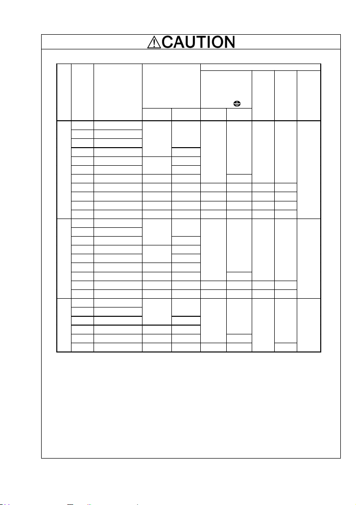
10. Use wires listed in EN60204 Appendix C.
of
w/o DCR
*1
*3
5
10
20
5
10
20
5
10
Applied
motor
Inverter type
rating
supply vol tage
(HP )
Power
1/8 FRNF12E1ع-2U
1/4 FRNF25E1ع-2U
1/2 FRNF50E1ع-2U
1 FRN001E1ع-2U
2 FRN002E1ع-2U 15
3 FRN003E1ع-2U
230 V
5 FRN005E1ع-2U 20 30
Thr ee- phase
7.5 FRN007E1ع-2U 30 50 4.0 6.0 4.0 4.0
10 FRN010E1ع-2U 40 75 6.0 10 6.0 6.0
15 FRN015E1ع-2U 50 100 10 16 10 16
20 FRN020E1ع-2U 75 125 16 25 16 25
1/2 FRNF50E1ع-4U
1 FRN001E1ع-4U
2 FRN002E1ع-4U
3 FRN003E1ع-4U 15
5 FRN005E1ع-4U
460 V
7.5 FRN007E1ع-4U 15 30
Three-phase
10 FRN010E1ع-4U 20 40
15 FRN015E1ع-4U 30 50 4.0 6.0 4.0 4.0
20 FRN020E1ع-4U 40 60 6.0 10 6.0 6.0
1/8 FRNF12E1ع-7U
1/4 FRNF25E1ع-7U
1/2 FRNF50E1ع-7U
1 FRN001E1ع-7U 10 15
230 V
Single-phase
2 FRN002E1ع-7U 15 20
3 FRN003E1ع-7U 20 30 4.0 6.0
Rated c urrent (A)
MCCB or RCD/GFCI
w/ DCR
5
10
5
10
5
Recom mended wire size (mm2)
Ma in circ uit
power input
[L1 /R, L2 /S, L3 /T]
[L1/L, L2/N]
Ground ing [
w/ DCR*3w/o DCR
2.5
2.5
2.5
*2
G]
2.5
4.0
2.5
4.0
2.5
4.0
DCR
[P1,
*2
P (+)]
Inverter
output
Braking
resistor
[U, V, W ]
[P (+),
DB]
2.5 2.5
2.5 2.5
2.5
2.5
4.0
*2
Control
circuit
(30A,
30B,
30C)
0.5
0.5
0.5
MCCB: Molded case circuit breaker RCD: Residual-current-operated protective device
GFCI: Ground fault circuit interrupter
Note 1) A box () in the above table replaces S (Standard type) or E (EMC filter built-in type)
depending on the product specifications
*1 The frame size and model of the MCCB or RCD/GFCI (with overcurrent protection) will vary,
depending on the power transformer capacity. Refer to the related technical documentation for
details.
*2 The recommended wire size for main circuits is for the 70qC(158qF) 600 V PVC wires used at an
ambient temperature of 40qC(104qF).
*3 In the case of no DC reactor, the wire sizes are determined on the basis of the effective input
current calculated under the condition that the power supply capacity and impedance are 500 kVA
and 5%, respectively.
.
vii
Page 10

Conformity to UL standards and Canadian standards (cUL certification)
If installed according to the guidelines given below, inverters marked with UL/cUL are considered as
compliant with the UL and CSA (cUL certified) standards.
1. Solid state motor overload protection (motor protection by electronic thermal overload relay)
is provided in each model.
Use function codes F10 to F12 to set the protection level.
2. Connect the power supply satisfying the characteristics shown in the table below as an
input power supply of the inverter. (Short circuit rating)
3. Use 75qC(167qF) Cu wire only.
4. Use Class 1 wire only for control circuits.
5. Field wiring connection must be made by a UL Listed and CSA Certified closed-loop
terminal connector sized for the wire gauge involved. Connector must be fixed using the
crimp tool specified by the connector manufacturer.
6. Short circuit rating
Suitable for use on a circuit capable of delivering not more than 100 kA rms symmetrical
amperes, 240 volts maximum for Three-phase or Single-phase 230 V input class.
Suitable for use on a circuit capable of delivering not more than 100 kA rms symmetrical
amperes, 480 volts maximum for Three-phase 460 V input class.
viii
Page 11
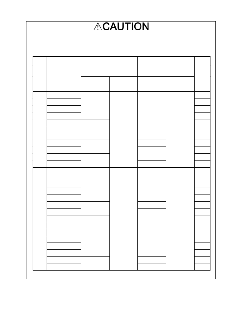
Conformity to UL standards and Canadian standards (cUL certification) (Continued)
7. Install UL/CSA certified circuit breaker rated 240 V or more for 230 V input, 480 V or more
for 460 V input between the power supply and the inverter, referring to the table below.
Standard type
Required torque
Power
supply
voltag e
Inverter type
FRNF12 E1S-2U 5
FRNF25 E1S-2U 5
FRNF50 E1S-2U 5
FRN001E1S-2U
FRN002E1S-2U 15
FRN003E1S-2U
FRN005E1S-2U
FRN007E1S-2U 8 50
Three- phase 230 V
FRN010E1S-2U
FRN015E1S-2U
FRN020E1S-2U
FRNF50 E1S-4U 5
FRN001E1S-4U 5
FRN002E1S-4U 10
FRN003E1S-4U 15
FRN005E1S-4U
FRN007E1S-4U 12 30
FRN010E1S-4U
Three- phase 460 V
FRN015E1S-4U
FRN020E1S-4U
FRNF12 E1S-7U 5
FRNF25 E1S-7U 5
FRNF50 E1S-7U 10
FRN001E1S-7U
FRN002E1S-7U 12 20
Single-phase 230 V
FRN003E1S-7U
Ib-in (N·m)
Main
terminal
10.6 (1.2)
15.9 (1.8)
33.6 (3.8)
51.3 (5.8)
15.9 (1.8) 14
33.6 (3.8)
51.3 (5.8)
10.6
(1.2)
15.9
(1.8)
Control circuit
4.4
(0.5)
3.5
(0.4)
4.4
(0.5)
Wire size
AWG or kcm il (mm
Main
terminal
14
10 30
6
4
10
8
14
10
2
)
Control circuit
20
(0.5)
20
(0.5)
20
(0.5)
Circuit breaker (A)
10
20
75
100
125
20
40
50
60
15
30
ix
Page 12
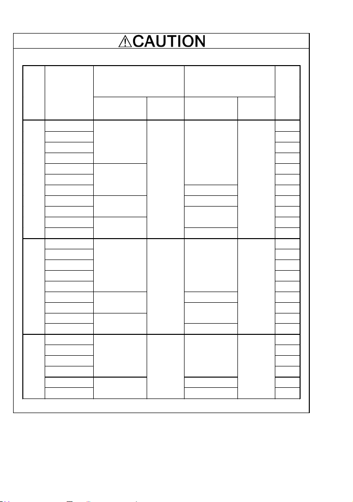
Conformity to UL standards and Canadian standards (cUL certification) (Continued)
EMC filter built-in type
Required torque
Power
supply
Inverter type
voltag e
FRNF12E1E-2U 5
FRNF25E1E-2U 5
FRNF50E1E-2U 5
FRN001E1E-2U
FRN002E1E-2U 15
FRN003E1E-2U
FRN005E1E-2U
FRN007E1E-2U 8 50
Three- phase 230 V
FRN010E1E-2U
FRN015E1E-2U
FRN020E1E-2U
FRNF50E1E-4U 5
FRN001E1E-4U 5
FRN002E1E-4U 10
FRN003E1E-4U 15
FRN005E1E-4U
FRN007E1E-4U 12 30
FRN010E1E-4U
Three- phase 460 V
FRN015E1E-4U
FRN020E1E-4U
FRNF12E1E-7U 5
FRNF25E1E-7U 5
FRNF50E1E-7U 10
FRN001E1E-7U
FRN002E1E-7U 12 20
Singl e-phase 230 V
FRN003E1E-7U
Ib-in (N·m)
Main
terminal
10.6 (1.2)
15.9 (1.8)
Output: 33.6 (3.8)
Input: 16.2 (1.8)
Output: 51.3 (5.8)
Input: 72.0 (8.1)
15.9 (1.8) 14
Output: 33.6 (3.8)
Input: 16.2 (1.8)
Output: 51.3 (5.8)
Input: 16.2 (1.8)
10.6
(1.2)
15.9
(1.8)
Control circuit
4.4
(0.5)
4.4
(0.5)
4.4
(0.5)
Wire size
AWG or kcmil (mm
Main
terminal
14
10 30
6
4
10
8
14
10
2
)
Control circuit
20
(0.5)
20
(0.5)
20
(0.5)
Circuit breaker (A)
10
20
75
100
125
20
40
50
60
15
30
x
Page 13

Precautions for use
Driving a 460 V
general-purpose
motor
Torque
characteristics
and temperature
rise
In running
generalpurpose
motors
Vibration
Noise
High-speed
motors
Explosion-proof
motors
Submersible
motors and
In running
special
motors
pumps
Brake motors
Geared motors
When driving a 460V general-purpose motor with an inverter
using extremely long wires, damage to the insulation of the
motor may occur. Use an output circuit filter (OFL) if
necessary after checking with the motor manufacturer. Fuji
motors do not require the use of output circuit filters because
of their reinforced insulation.
When the inverter is used to run a general-purpose motor,
the temperature of the motor becomes higher than when it is
operated using a commercial power supply. In the low-speed
range, the cooling effect will be weakened, so decrease the
output torque of the motor.
When an inverter-driven motor is mounted to a machine,
resonance may be caused by the natural frequencies of the
machine system.
Note that operation of a 2-pole motor at 60 Hz or higher may
cause abnormal vibration.
* The use of a rubber coupling or vibration-proof rubber is
recommended.
* Use the inverter's jump frequency control feature to skip
the resonance frequency zone(s).
When an inverter is used with a general-purpose motor, the
motor noise level is higher than that with a commercial power
supply. To reduce noise, raise carrier frequency of the
inverter. Operation at 60 Hz or higher can also result in
higher noise level.
If the reference frequency is set to 120 Hz or more to drive a
high-speed motor, test-run the combination of the inverter
and motor beforehand to check for safe operation.
When driving an explosion-proof motor with an inverter, use
a combination of a motor and an inverter that has been
approved in advance.
These motors have a larger rated current than
general-purpose motors. Select an inverter whose rated
output current is greater than that of the motor.
These motors differ from general-purpose motors in thermal
characteristics. Set a low value in the thermal time constant
of the motor when setting the electronic thermal function.
For motors equipped with parallel-connected brakes, their
power supply for brake must be supplied from the primary
circuit. If the power supply for brake is connected to the
inverter's output circuit by mistake, the brake will not work.
Do not use inverters for driving motors equipped with
series-connected brakes.
If the power transmission mechanism uses an oil-lubricated
gearbox or speed changer/reducer, then continuous
operation at low speed may cause poor lubrication. Avoid
such operation.
xi
Page 14

In running
special
motors
Environmental
conditions
Combination with
peripheral
devices
Synchronous
motors
Single-phase
motors
Installation
location
Installing an
MCCB or
RCD/GFCI
Installing an MC
in the secondary
circuit
Installing an MC
in the primary
circuit
Protecting the
motor
It is necessary to take special measures suitable for this
motor type. Consult your Fuji Electric representative for
details.
Single-phase motors are not suitable for inverter-driven
variable speed operation. Use three-phase motors.
Even if a single-phase power supply is available, use a
three-phase motor as the inverter provides three-phase
output.
Use the inverter within the ambient temperature range from
–10qC(14qF) to +50qC(122qF).
The heat sink and braking resistor of the inverter may
become hot under certain operating conditions, so install the
inverter on nonflammable material such as metal.
Ensure that the installation location meets the environmental
conditions specified in Chapter 2, Section 2.1 "Operating
Environment."
Install a recommended molded case circuit breaker (MCCB)
or residual-current-operated protective device (RCD)/a
ground fault circuit interrupter (GFCI) (with overcurrent
protection) in the primary circuit of the inverter to protect the
wiring. Ensure that the circuit breaker rated current is
equivalent to or lower than the recommended rated current.
If a magnetic contactor (MC) is mounted in the inverter's
output (secondary) circuit for switching the motor to
commercial power or for any other purpose, ensure that both
the inverter and the motor are completely stopped before you
turn the MC ON or OFF.
Remove the magnet contactor (MC) already installed and
built-in surge killer from the inverter's output (secondary)
circuit before installing the MC to switch the motor power.
Do not turn the magnetic contactor (MC) in the primary circuit
ON or OFF more than once an hour as an inverter failure
may result.
If frequent starts or stops are required during motor
operation, use terminal [FWD]/[REV] signals or the
key.
The electronic thermal function of the inverter can protect the
motor. The operation level and the motor type
(general-purpose motor, inverter motor) should be set. For
high-speed motors or water-cooled motors, set a small value
for the thermal time constant and protect the motor.
/
If you connect the motor thermal relay to the motor with a
long wire, a high-frequency current may flow into the wiring
stray capacitance. This may cause the relay to trip at a
current lower than the set value for the thermal relay. If this
happens, lower the carrier frequency or use the output circuit
filter (OFL).
xii
Page 15

Combination with
peripheral
devices
Wiring
Selecting
inverter
capacity
Discontinuance
of power
capacitor for
power factor
correction
Discontinuance
of surge killer
Reducing noise
Do not mount power capacitors for power factor correction in
the inverter’s primary circuit. (Use the DC reactor to correct
the inverter power factor.) Do not use power capacitors for
power factor correction in the inverter’s output (secondary)
circuit. An overcurrent trip will occur, disabling motor
operation.
Do not connect a surge killer to the inverter's output
(secondary) circuit.
Use of a filter and shielded wires is typically recommended to
satisfy EMC Directive.
If an overvoltage trip occurs while the inverter is stopped or
Measures against
surge currents
operated under a light load, it is assumed that the surge
current is generated by open/close of the power capacitor for
power factor correction in the power system.
* Connect a DC reactor to the inverter.
Megger test
Control circuit
wiring length
Wiring length
between inverter
and motor
When checking the insulation resistance of the inverter, use
a 500 V megger and follow the instructions contained in
Chapter 7, Section 7.5 "Insulation Test."
When using remote control, limit the wiring length between
the inverter and operator panel to 66ft (20 m) or less and use
twisted pair or shielded wire.
If long wiring is used between the inverter and the motor, the
inverter will overheat or trip as a result of overcurrent
(high-frequency current flowing into the stray capacitance) in
the wires connected to the phases. Ensure that the wiring is
shorter than 164ft (50 m). If this length must be exceeded,
lower the carrier frequency or mount an output circuit filter
(OFL).
Wiring size
Wiring type
Select wires with a sufficient capacity by referring to the
current value or recommended wire size.
When several inverters drive motors, do not use one
multicore cable in order to connect several inverters with
motors.
Grounding Securely ground the inverter using the grounding terminal.
Select an inverter according to the nominal applied motor
Driving
general-purpose
motor
Driving special
motors
rating listed in the standard specifications table for the
inverter.
When high starting torque is required or quick acceleration or
deceleration is required, select an inverter with one rank
larger capacity than the standard.
Select an inverter that meets the following condition:
Inverter rated current > Motor rated current
xiii
Page 16

Transportation and
storage
When exporting an inverter built in a panel or equipment, pack them in a previously
fumigated wooden crate. Do not fumigate them after packing since some parts
inside the inverter may be corroded by halogen compounds such as methyl
bromide used in fumigation.
When packing an inverter alone for export, use a laminated veneer lumber (LVL).
For other transportation and storage instructions, see Chapter 1, Section 1.3
"Transportation" and Section 1.4 "Storage Environment."
xiv
Page 17

How this manual is organized
r
This manual is made up of chapters 1 through 10.
Chapter 1 BEFORE USING THE INVERTER
This chapter describes acceptance inspection and precautions for transportation and storage of the
inverter.
Chapter 2 MOUNTING AND WIRING OF THE INVERTER
This chapter provides operating environment, precautions for installing the inverter, wiring
instructions for the motor and inverter.
Chapter 3 OPERATION USING THE KEYPAD
This chapter describes inverter operation using the keypad. The inverter features three operation
modes (Running, Programming and Alarm modes) which enable you to run and stop the motor,
monitor running status, set function code data, display running information required for maintenance,
and display alarm data.
Chapter 4 RUNNING THE MOTOR
This chapter describes preparation to be made before running the motor for a test and practical
operation.
Chapter 5 FUNCTION CODES
This chapter provides a list of the function codes. Function codes to be used often and irregular ones
are described individually.
Chapter 6 TROUBLESHOOTING
This chapter describes troubleshooting procedures to be followed when the inverter malfunctions or
detects an alarm condition. In this chapter, first check whether any alarm code is displayed or not,
and then proceed to the troubleshooting items.
Chapter 7 MAINTENANCE AND INSPECTION
This chapter describes inspection, measurement and insulation test which are required for safe
inverter operation. It also provides information about periodical replacement parts and guarantee of
the product.
Chapter 8 SPECIFICATIONS
This chapter lists specifications including output ratings, control system, external dimensions and
protective functions.
Chapter 9 LIST OF PERIPHERAL EQUIPMENT AND OPTIONS
This chapter describes main peripheral equipment and options which can be connected to the
FRENIC-Multi series of inverters.
Chapter 10 COMPLIANCE WITH STANDARDS
This chapter describes standards with which the FRENIC-Multi series of inverters comply.
Icons
The following icons are used throughout this manual.
This icon indicates information which, if not heeded, can result in the inverter not operating
to full efficiency, as well as information concerning incorrect operations and settings which
can result in accidents.
This icon indicates information that can prove handy when performing certain settings o
operations.
This icon indicates a reference to more detailed information.
xv
Page 18

Table of Content
Preface ............................................................ i
Safety precautions..................................................i
Precautions for use ..............................................xi
How this manual is organized .................................xv
Chapter 1 BEFORE USING THE INVERTER..... 1-1
1.1 Acceptance Inspection .............................. 1-1
1.2 External View and Terminal Blocks ........... 1-2
1.3 Transportation........................................... 1-3
1.4 Storage Environment................................. 1-3
1.4.1 Temporary storage ............................ 1-3
1.4.2 Long-term storage............................. 1-3
Chapter 2 MOUNTING AND WIRING OF THE
Chapter 3 OPERATION USING THE KEYPAD... 3-1
INVERTER ......................................... 2-1
2.1 Operating Environment ............................. 2-1
2.2 Installing the Inverter................................. 2-1
2.3 Wiring........................................................ 2-4
2.3.1 Removing and mounting the terminal
cover and the main circuit terminal
block cover........................................ 2-4
2.3.2 Terminal arrangement diagram and
screw specifications ..........................2-7
2.3.3 Recommended wire sizes ............... 2-10
2.3.4 Wiring precautions ...........................2-11
2.3.5 Wiring for main circuit terminals and
grounding terminals..........................2-11
2.3.6 Wiring for control circuit terminals... 2-16
2.3.7 Setting up the slide switches ........... 2-23
2.4 Mounting and Connecting a Keypad ....... 2-25
2.4.1 Mounting style and parts needed
for connection.................................. 2-25
2.4.2 Mounting/installing steps................. 2-26
2.5 Cautions Relating to Harmonic Component,
Noise, and Leakage Current ...................2-28
3.1 LED Monitor, Keys and LED Indicators
on the Keypad........................................... 3-1
3.2 Overview of Operation Modes................... 3-2
3.3 Running Mode........................................... 3-4
3.3.1 Monitoring the running status ............ 3-4
3.3.2 Setting up frequency and PID
commands......................................... 3-6
3.3.3 Running/stopping the motor.............3-11
3.4 Programming Mode..................................3-11
3.4.1 Setting up basic function codes quickly
-- Menu #0 "Quick Setup" -- ............ 3-13
3.4.2 Setting up function codes
-- Menu #1 "Data Setting" --............ 3-15
3.4.3 Checking changed function codes
-- Menu #2 "Data Checking" -- ........3-16
3.4.4 Monitoring the running status
-- Menu #3 "Drive Monitoring" --...... 3-16
3.4.5 Checking I/O signal status
-- Menu #4 "I/O Checking" --........... 3-19
3.4.6 Reading maintenance information
-- Menu #5 "Maintenance Information" --
........................................................ 3-23
3.4.7 Reading alarm information
-- Menu #6 "Alarm Information" --.... 3-25
3.5 Alarm Mode............................................. 3-27
Chapter 4 RUNNING THE MOTOR .................... 4-1
4.1 Running the Motor for a Test..................... 4-1
4.1.1 Inspection and preparation prior to
powering on....................................... 4-1
4.1.2 Turning ON power and checking ....... 4-1
4.1.3 Preparation before running the motor
for a test--Setting function code data.4-2
4.1.4 Test run ............................................. 4-4
4.2 Operation................................................... 4-5
4.2.1 Jogging Operation............................. 4-5
Chapter 5 FUNCTION CODES ........................... 5-1
5.1 Function Code Tables................................ 5-1
5.2 Overview of Function Codes ................... 5-18
Chapter 6 TROUBLESHOOTING .......................6-1
6.1 Before Proceeding with Troubleshooting... 6-1
6.2 If No Alarm Code Appears on the LED
Monitor ......................................................6-2
6.2.1 Motor is running abnormally ..............6-2
6.2.2 Problems with inverter settings ......... 6-8
6.3 If an Alarm Code Appears on the LED
Monitor ....................................................6-10
6.4 If an Abnormal Pattern Appears on the
LED Monitor while No Alarm Codeis
Displayed................................................. 6-24
Chapter 7 MAINTENANCE AND INSPECTION.. 7-1
7.1 Daily Inspection ......................................... 7-1
7.2 Periodic Inspection .................................... 7-1
7.3 List of Periodical Replacement Parts......... 7-3
7.3.1 Judgment on service life.................... 7-4
7.4 Measurement of Electrical Amounts in
Main Circuit ............................................... 7-6
7.5 Insulation Test ........................................... 7-8
7.6 Inquiries about Product and Guarantee..... 7-9
7.6.1 W hen making an inquiry.................... 7-9
7.6.2 Product warranty...............................7-9
Chapter 8 SPECIFICATIONS.............................. 8-1
8.1 Standard Models ....................................... 8-1
8.1.1 Three-phase 230 V class series........ 8-1
8.1.2 Three-phase 460 V class series........ 8-2
8.1.3 Single-phase 230 V class series ....... 8-3
8.2 Models Available on Order
(EMC filter built-in type)............................. 8-4
8.2.1 Three-phase 230 V class series........ 8-4
8.2.2 Three-phase 460 V class series........ 8-4
3 Single-phase 230 V class series ....... 8-4
8.2.
8.3 Specifications of Keypad Related.............. 8-5
8.3.1 General specifications of keypad....... 8-5
8.3.2 Communications specifications of
keypad............................................... 8-5
8.4 Terminal Specifications.............................. 8-6
8.4.1 Terminal functions ............................. 8-6
8.4.2 Running the inverter with keypad ......8-6
8.4.3 Running the inverter by terminal
commands......................................... 8-7
8.5 External Dimensions ................................. 8-8
8.5.1 Standard models...............................8-8
8.5.2 Models Available on Order
(EMC filter built-in type)................... 8-11
8.5.3 Standard keypad.............................8-14
8.6 Protective Functions................................ 8-15
xvi
Page 19

Chapter 9 LIST OF PERIPHERAL EQUIPMENT
Chapter 10 COMPLIANCE WITH STANDARDS. 10-1
AND OPTIONS................................... 9-1
10.1 Compliance with UL Standards and
Canadian Standards (cUL certification) ... 10-1
10.1.1 General........................................ 10-1
10.1.2 Considerations when using
FRENIC-Multi in systems to be
10.2 Compliance with European Standards .... 10-1
10.3 Compliance with EMC Standards............ 10-2
10.4 Harmonic Component Regulation in the
10.5 Compliance with the Low Voltage Directive
certified by UL and cUL................10-1
10.3.1 General ........................................... 10-2
10.3.2 Recommended installation
procedure........................................ 10-2
10.3.3 Leakage current from EMC-filter
built-in type inverters or inverters with
an external EMC-complaint filter
(optional) .........................................10-5
EU ...........................................................10-7
10.4.1 General comments.......................... 10-7
10.4.2 Compliance with the harmonic
component regulation...................... 10-8
in the EU.................................................. 10-8
10.5.1 General ........................................... 10-8
10.5.2 Points for consideration when using
the FRENIC-Multi series in a system
to be certified by the Low Voltage
Directive in the EU........................... 10-8
xvii
Page 20
Chapter 1 BEFORE USING THE INVERTER
002
1.1 Acceptance Inspection
Unpack the package and check the following:
(1) An inverter and accessories below are contained in the package.
• Cooling fan fixing screws (for inverters of 7.5 to 20 HP)
• Keypad rear cover (with fixing screws)
• Instruction manual (this manual)
(2) The inverter has not been damaged during transportation—there should be no dents or parts
missing.
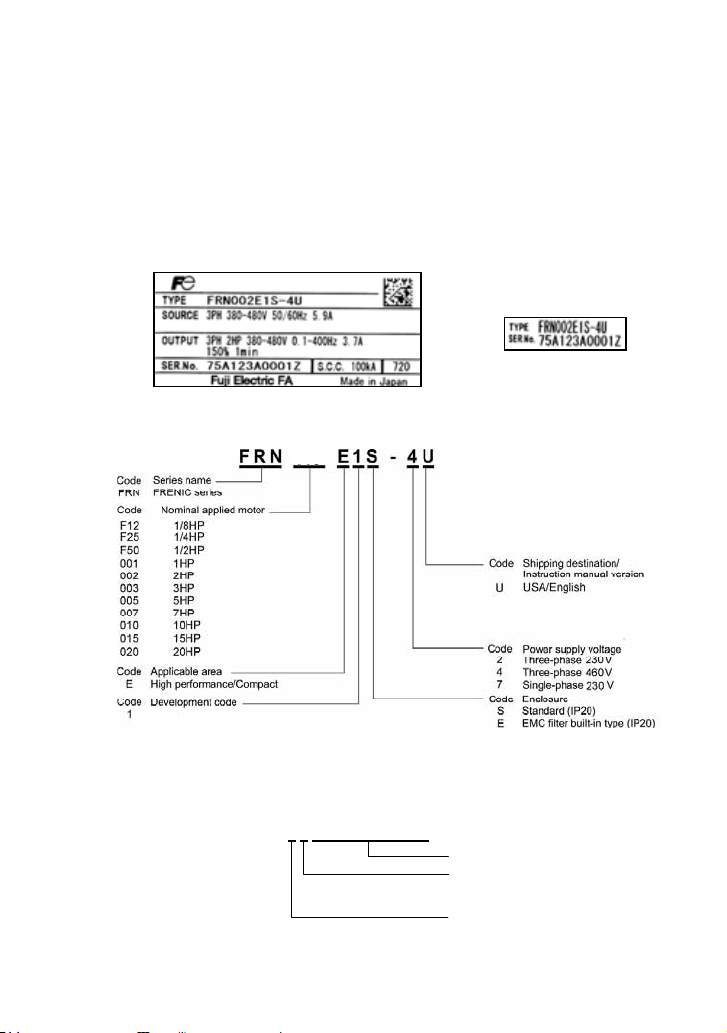
(3) The inverter is the model you ordered. You can check the model name and specifications on the
main nameplate. (Main and sub nameplates are attached to the inverter and are located as
shown on the following page.)
(a) Main Nameplate (b) Sub Nameplate
Figure 1.1 Nameplates
TYPE: Type of inverter
㩷
SOURCE: Number of input phases (three-phase: 3PH, single-phase: 1PH), input voltage, input
OUTPUT: Number of output phases, rated output capacity, rated output voltage, output frequency
SER. No.: Product number
If you suspect the product is not working properly or if you have any questions about your product,
contact your Fuji Electric representative.
frequency, input current
range, rated output current, overload capacity
5 A 1 2 3 A 0 0 0 1 Z
7
Serial number of production lot
Production month
1 to 9: January to September
X, Y, or Z: October, November, or December
Production year: Last digit of year
1-1
Page 21
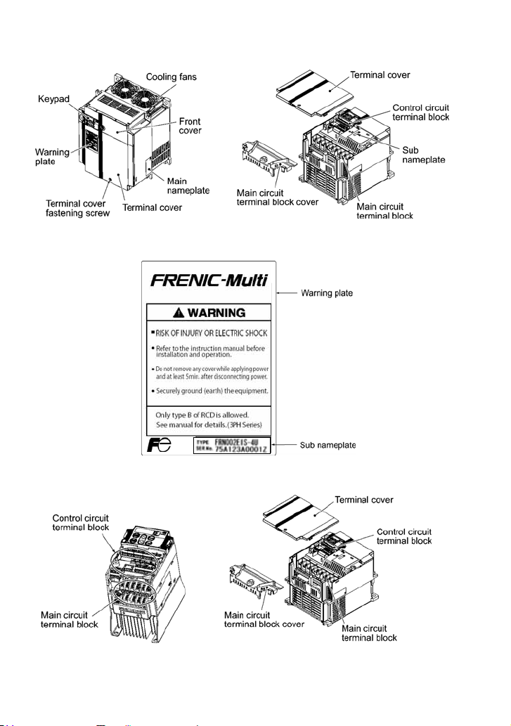
1.2 External View and Terminal Blocks
(1) Outside and inside views
Figure 1.2 Outside and Inside Views of Inverters (FRN020E1S-2U)
(2) Warning plates and label
(3) Terminal block location
Figure 1.3 Warning Plate and Sub Nameplate
(a) FRN001E1S-2U
(b) FRN020E1S-2U
Figure 1.4 Terminal Blocks
1-2
Page 22

1.3 Transportation
• When carrying an inverter, always support its bottom at the right and left sides with both hands. Do
not hold covers or individual parts only.
• Avoid applying excessively strong force to the terminal block covers as they are made of plastic
and are easily broken.
1.4 Storage Environment
1.4.1 Temporary storage
Store the inverter in an environment that satisfies the requirements listed in Table 1.1.
Table 1.1 Environmental Requirements for Storage and Transportation
Item Requirements
Storage temperature *1 -25(-13qF) to
Relative humidity 5 to 95% *
Atmosphere The inverter must not be exposed to dust, direct sunlight, corrosive or
*1Assuming a comparatively short storage period (e.g., during transportation or the like).
2
*
Even if the humidity is within the specified requirements, avoid such places where the inverter will be
subjected to sudden changes in temperature that will cause condensation to form.
+70qC(158qF)
flammable gases, oil mist, vapor, water drops or vibration. The atmosphere
must contain only a low level of salt. (0.01 mg/cm
86 to 106 kPa (in storage) Atmospheric pressure
70 to 106 kPa (during transportation)
Precautions for temporary storage
(1) Do not leave the inverter directly on the floor.
(2) If the environment does not satisfy the specified requirements, wrap the inverter in an airtight
vinyl sheet or the like for storage.
(3) If the inverter is to be stored in an environment with a high level of humidity, put a drying agent
(such as silica gel) in the airtight package described in item (2).
A location where the inverter is not subject to abrupt changes
in temperature that would result in the formation of
condensation or ice.
2
2
or less per year)
1.4.2 Long-term storage
The long-term storage methods for the inverter vary largely according to the environment of the
storage site. General storage methods are described below.
(1) The storage site must satisfy the requirements specified for temporary storage.
However, for storage exceeding three months, the ambient temperature should be within the
range from -10°C(14qF) to +30°C(86qF). This is to prevent the electrolytic capacitors in the
inverter from deteriorating.
(2) The inverter must be stored in a package that is airtight to protect it from moisture. Include a
drying agent inside the package to maintain the relative humidity inside the package within 70%.
(3) If the inverter has been installed in the equipment or control panel at a construction site where it
may be subjected to humidity, dust or dirt, then remove the inverter and store it in a suitable
environment specified in Table 1.1.
Precautions for storage over 1 year
If the inverter will not be powered on for a long time, the property of the electrolytic capacitors may
deteriorate. Power the inverters on once a year and keep them on for 30 to 60 minutes. Do not
connect the inverter to a motor or run the motor.
1-3
Page 23
Chapter 2 MOUNTING AND WIRING OF THE INVERTER
r
r
r
2.1 Operating Environment
Install the inverter in an environment that satisfies the requirements listed in Table 2.1.
Table 2.1 Environmental Requirements
Item Specifications
Site location Indoors
Ambient
temperature
Relative
humidity
Atmosphere
Altitude 3300ft (1000 m) max. (Note 3)
Atmospheric
pressure
Vibration
-10qC(14qF) to +50qC(122qF) (Note 1)
5 to 95% (No condensation)
The inverter must not be exposed to dust,
direct sunlight, corrosive gases, flammable
gas, oil mist, vapor or water drops.
The atmosphere can contain only a low level
of salt.
(0.01 mg/cm
The inverter must not be subjected to sudden
changes in temperature that will cause
condensation to form.
86 to 106 kPa
0.12inch(3 mm)
(Max. amplitude)
9.8 m/s2 9 to less than 20 Hz
2 m/s2 20 to less than 55 Hz
1 m/s
2
or less per year)
2 to less than 9 Hz
2
55 to less than 200 Hz
(Note 2)
2.2 Installing the Inverter
(1) Mounting base
The temperature of the heat sink will rise up to approx.
90°C(194qF) during operation of the inverter, so the
inverter should be mounted on a base made of material
that can withstand temperatures of this level.
Table 2.2
Output Current Derating Factor
in Relation to Altitude
Altitude
3300ft (1000m) or
lower
3300ft (1000) to
4900ft (1500m)
4900ft (1500) to
6600ft (2000m)
6600ft (2000) to
8200ft (2500m)
8200ft (2500) to
9800ft (3000m)
(Note 1) When inverters are mounted
side-by-side without any gap between them
(less than 7.5HP), the ambient temperature
should be within the range from –10qC(14qF)
to +40qC(104qF).
(Note 2) Do not install the inverter in an
environment where it may be exposed to
cotton waste or moist dust or dirt which will
clog the heat sink in the inverter. If the
inverter is to be used in such an environment,
install it in the panel of your system or othe
dustproof containers.
(Note 3) If you use the inverter in an altitude
above 3300ft(1000 m), you should apply an
output current derating factor as listed in
Table 2.2.
Output current
derating factor
1.00
0.97
0.95
0.91
0.88
Install the inverter on a base constructed from metal or
other non-flammable material.
A fire may result with other material.
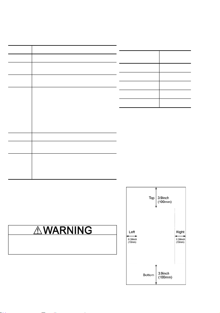
(2) Clearances
Ensure that the minimum clearances indicated in Figure
2.1 are maintained at all times. When installing the inverte
in the panel of your system, take extra care with ventilation
inside the panel as the temperature around the inverte
will tend to increase. Do not install the inverter in a small
panel with poor ventilation.
2-1
Figure 2.1 Mounting Direction and
Required Clearances
Page 24
When mounting two or more inverters
Horizontal layout is recommended when two or more
inverters are to be installed in the same unit or panel. If it is
necessary to mount the inverters vertically, install a partition
plate or the like between the inverters so that any heat
radiating from an inverter will not affect the one/s above. As
long as the ambient temperature is 40°C (104qF) or lower,
inverters can be mounted side-by-side without any gap
between them (only for inverters with a capacity of less than
7.5 HP).
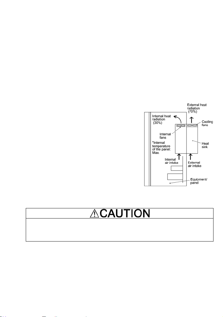
When employing external cooling
At the shipment time, the inverter is set up for mount inside
your equipment or panel so that cooling is done all internally.
To improve cooling efficiently, you can take the heat sink out
of the equipment or the panel (as shown on the right) so that
cooling is done both internally and externally (this is called
"external cooling").
In external cooling, the heat sink, which dissipates about
70% of the total heat (total loss) generated into air, is situated
outside the equipment or the panel. As a result, much less
heat is radiated inside the equipment or the panel.
To take advantage of external cooling, you need to use the
external cooling attachment option for inverters with a
capacity of 7.5 HP or above.
In an environment with high humidity or a lot of fibrous dust,
however, do not use external cooling in an environment with
high humidity or a lot of fibrous dust, which tends to clog the
heat sink.
For details, refer to the Mounting Adapter for
External Cooling "PB-F1/E1" Installation Manual.
50°C
(122°F)"
Figure 2.2 External Cooling
Prevent lint, paper fibers, sawdust, dust, metallic chips, or other foreign materials from getting
into the inverter or from accumulating on the heat sink.
This may result in a fire or accident.
2-2
Page 25
(3) Mounting direction
Mount the inverter vertically to the mounting surface and fix it securely with four screws or bolts so
that the logo "FRENIC-Multi" can be seen from the front.
Do not mount the inverter upside down or horizontally. Doing so will reduce the heat
dissipation efficiency of the inverter and cause the overheat protection function to operate,
so the inverter will not run.
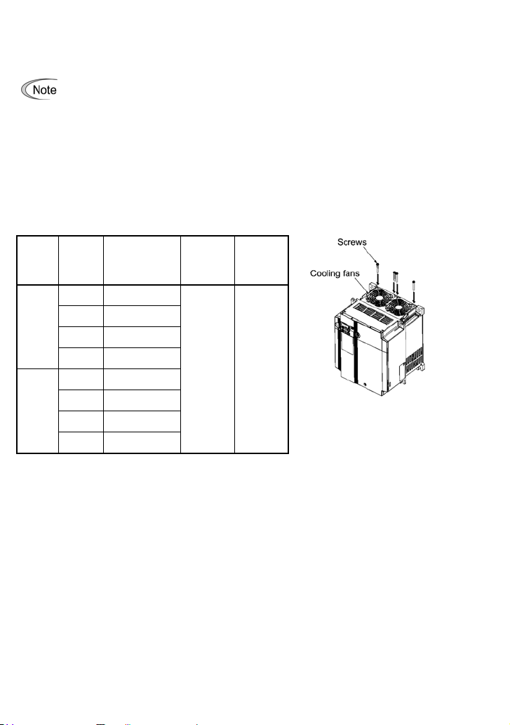
(4) Solving abnormal vibration after installation
If any vibration in the surroundings reaches the inverter and causes abnormal vibration to the cooling
fans or the keypad, fix them firmly using the fixing screws provided as accessories.
Fixing the cooling fans
Table 2.3 Fixing Screws
Nominal
Power
supply
voltage
Three-
Three-
Note 1) A box () in the above table replaces S or E depending on
phase
230 V
phase
460 V
applied
motor
(HP)
7.5
10
15
20
7.5
10
15
20
the enclosure.
Inverter
type
FRN007E1ع-2U
FRN010E1ع-2U
FRN015E1ع-2U
FRN020E1ع-2U
FRN007E1ع-4U
FRN010E1ع-4U
FRN015E1ع-4U
FRN020E1ع-4U
Screw
(accessory)
M4x35
(4 pcs)
size
Tightening
torque
(N·m)
0.8
Figure 2.3 Fixing the Cooling Fans
2-3
Page 26
2.3 Wiring
Follow the procedure below. (In the following description, the inverter has already been installed.)
2.3.1 Removing and mounting the terminal cover and the main circuit terminal block cover
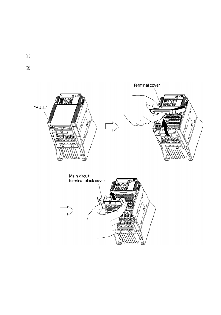
(1) For inverters with a capacity of 5HP or below
To remove the terminal cover, put your finger in the dimple of the terminal cover (labeled
"PULL"), and then pull it up toward you.
To remove the main circuit terminal block cover, hold its right and left ends with your fingers and
slide it toward you.
Figure 2.4 Removing the Covers (For Inverters with a Capacity of 5HP or below)
2-4
Page 27
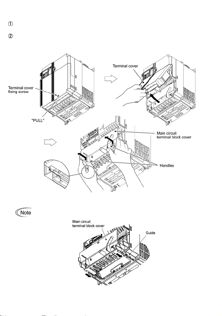
(2) For inverters with a capacity of 7.5 and 10 HP
To remove the terminal cover, first loosen the terminal cover fixing screw on it, and put your
finger in the dimple of the terminal cover (labeled "PULL"), and then pull it up toward you.
To remove the main circuit terminal block cover, put your thumbs on the handles of the main
circuit terminal block cover, and push it up while supporting it with your fingers. (Refer to Figure
2.5.)
Figure 2.5 Removing the Covers (For Inverters with a Capacity of 7.5 and 10 HP)
When mounting the main circuit terminal block cover, fit it according to the guide on the
inverter.
Figure 2.6 Mounting the main circuit terminal block cover
(For Inverters with a Capacity of 7.5 and 10HP)
2-5
Page 28
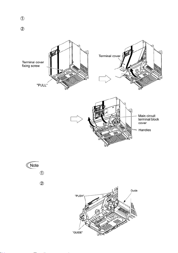
(3) For inverters with a capacity of 15 and 20 HP
To remove the terminal cover, first loosen the terminal cover fixing screw on it, and put your
finger in the dimple of the terminal cover (labeled "PULL"), and then pull it up toward you.
To remove the main circuit terminal block cover, hold the handles on the both sides of the main
circuit terminal block cover, and pull it up.
Figure 2.7 Removing the Covers (For Inverters with a Capacity of 15 and 20 HP)
When mounting the main circuit terminal block cover, fit it according to the guide on the
inverter.
Insert the main circuit terminal block cover by fitting the part labeled "GUIDE"
according to the guide on the inverter.
Push where "PUSH" are labeled to snap it into the inverter.
Figure 2.8 Mounting the Main Circuit Terminal Block Cover
(For Inverters with a Capacity of 15 and 20 HP)
2-6
Page 29

2.3.2 Terminal arrangement diagram and screw specifications
The table below shows the main circuit screw sizes, tightening torque and terminal arrangements.
Note that the terminal arrangements differ according to the inverter types. Two terminals designed
for grounding shown as the symbol,
supply source (a primary circuit) and a motor (a secondary circuit).
G in Figures A to E make no distinction between a power
(1) Arrangement of the main circuit terminals
Table 2.4 Main Circuit Terminal Properties
Nominal
Power
supply
voltage
Three-
phase
230 V
Three-
phase
460 V
Single-
phase
230 V
applied
motor
(HP)
1/8 FRNF12E1ع-2U
1/4 FRNF25E1ع-2U
1/2 FRNF50E1ع-2U
1 FRN001E1ع-2U
2 FRN002E1ع-2U
3 FRN003E1ع-2U
5 FRN005E1ع-2U
7.5
10
15
20
1/2 FRNF50E1ع-4U
1 FRN001E1ع-4U
2 FRN002E1ع-4U
3 FRN003E1ع-4U
5
7.5
10
15
20
1/8 FRNF12E1ع-7U
1/4 FRNF25E1ع-7U
1/2 FRNF50E1ع-7U
1 FRN001E1ع-7U
2 FRN002E1ع-7U
3 FRN003E1ع-7U
Inverter type
FRN007E1S-2U M5 33.6(3.8) Figure C
FRN007E1E-2U
FRN010E1S-2U M5 33.6(3.8) Figure C
FRN010E1E-2U
FRN015E1S-2U 51.3(5.8) Figure C
FRN015E1E-2U 71.7(8.1)
FRN020E1S-2U 51.3(5.8) Figure C
FRN020E1E-2U
FRN005E1ع-4U
FRN007E1S-4U
FRN007E1E-4U
FRN010E1S-4U
FRN010E1E-4U
FRN015E1S-4U
FRN015E1E-4U
FRN020E1S-4U
FRN020E1E-4U
Terminal
screw
size
M3.5
M4
Input: M4
Output: M5
Input: M4
Output: M5
M6
M4
M5 33.6(3.8) Figure C
Input: M4
Output: M5
M5 33.6(3.8) Figure C
Input: M4
Output: M5
M6 51.3(5.8) Figure C
Input: M4
Output: M6
M6 51.3(5.8) Figure C
Input: M4
Output: M6
M3.5
M4
Tightening
torque
(Ib-in (N·m))
10.6
(1.2)
15.9
(1.8)
15.9(1.8)
15.9(1.8)
71.7(8.1)
15.9
(1.8)
15.9(1.8)
15.9(1.8)
15.9(1.8)
15.9(1.8)
10.6
(1.2)
15.9
(1.8)
Ground-
ing screw
size
M3.5
M4
M5
M5
M6
M6
M4
M5
M5
M6
M6
M3.5
M4
Tightening
torque
(Ib-in (N·m))
10.6
(1.2)
15.9
(1.8)
33.6
(3.8)
33.6
(3.8)
51.3
(5.8)
51.3
(5.8)
15.9
(1.8)
33.6
(3.8)
33.6
(3.8)
51.3
(5.8)
51.3
(5.8)
10.6
(1.2)
15.9
(1.8)
Refer to:
Figure A
Figure B
Figure F
Figure F
Figure F
Figure F
Figure B
Figure F
Figure F
Figure F
Figure F
Figure D
Figure E
Note 1) A box () in the above table replaces S or E depending on the enclosure.
2-7
Page 30
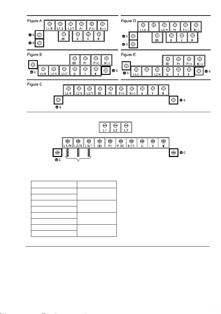
Figure F
(Note 1)
(Note 1) Terminal screw type is listed in the table below.
Inverter type Screw type
Filter output (Note 2)
FRN007E1E-2U
FRN010E1E-2U
FRN015E1E-2U
FRN020E1E-2U
FRN007E1E-4U
FRN010E1E-4U
FRN015E1E-4U
FRN020E1E-4U
Cross
Hxagon
Flat
Cross
(Note 2) Cables of EMC filter output are already connected to inverter input by factory default.
2-8
Page 31

(2) The control circuit terminals (common to all models)
Screw size: M3 Tightening torque: 4.4 to 5.3 (lb-in) (0.5 to 0.6 (N·m))
Table 2.5 Control Circuit Terminal Block
Wire strip length
Screwdriver type Allowable wire size
Dimension of openings in the control
circuit terminals for ferrule
(for Europe type terminal block)*
Flat screw driver
0.02 x 1.38 inch
(0.6 x 3.5 mm)
* Manufacturer of ferrules: Phoenix Contact Inc. Refer to Table 2.6.
Screw size
AWG24 (0.25 mm2) AI0.25-6BU
AWG22 (0.34 mm2)
AWG20 (0.5 mm2)
AWG18 (0.75 mm2)
AWG26 to AWG16
(0.14 to 1.5 mm
2
)
0.24 inch (6 mm)
Table 2.6 Recommended Ferrule Terminals
Type
With insulated collar Without insulated collar
-
AI0.34-6TQ
AI0.5-6WH
AI0.75-6GY
A0.34-7
A0.5-6
A0.75-6
AWG16 (1.25 mm2) AI1.5-6BK A1.5-7
0.1(W) x 0.07(H) inch
(2.51 (W) x 1.76 (H) mm)
Head thickness: 0.02 inch
Screwdriver head style
0.14 inch
(3.5 mm)
(0.6 mm)
2-9
Page 32

2.3.3 Recommended wire sizes
Table 2.7 lists the recommended wire sizes. The recommended wire sizes for the main circuits are
examples of using HIV single wire for 75qC (167qF) at an ambient temperature of 50qC (122qF).
Table 2.7 Recommended Wire Sizes
Recommended wire size AWG(mm
2
)*1
Main circuits
Main circuit
power input
[L1/R, L2/S, L3/T]
[L1/L, L2/N]
w/ DCR w/o DCR
Ground-
ing
G]
[
Inverter
output
[U, V, W]
DCR
[P1,
P (+)]
Braking
resistor
[P(+),
DB]
Control
circuit
Power supply voltage
Nominal
applied
motor
Inverter type
1/8 FRNF12E1䂓-2U
1/4 FRNF25E1䂓-2U
1/2 FRNF50E1䂓-2U
1 FRN001E1䂓-2U
2 FRN002E1䂓-2U
3 FRN003E1䂓-2U
5 FRN005E1䂓-2U
7.5 FRN007E1䂓-2U
Three-phase 230 V
10 FRN010E1䂓-2U 11(3.5) 9(5.5)
15 FRN015E1䂓-2U 9(5.5) 5(14)
14
(2)
14
14
(2)
14
(2)14(2)
11(3.5)
8(8) 8(8)
9(5.5)
(2)
11(3.5) 11(3.5) 11(3.5)
9(5.5)
20
(0.5)
14
to
(2)
16
(1.25)
20 FRN020E1䂓-2U 5(14) 3(22) 8(8) 5(14) 5(14)
1/2 FRNF50E1䂓-4U
1 FRN001E1䂓-4U
2 FRN002E1䂓-4U
3 FRN003E1䂓-4U
5 FRN005E1䂓-4U
7.5 FRN007E1䂓-4U
10 FRN010E1䂓-4U
Three-phase 460 V
15 FRN015E1䂓-4U
20 FRN020E1䂓-4U 11(3.5) 9(5.5)
1/8 FRNF12E1䂓-7U
1/4 FRNF25E1䂓-7U
1/2 FRNF50E1䂓-7U
1 FRN001E1䂓-7U
230 V
2 FRN002E1䂓-7U
Three-phase
3 FRN003E1䂓-7U
14
14
14
(2)
11(3.5)
(2)
(2)
11( 3.5 )
14
14
(2)
(2)
11(3.5)
11(3.5) 9(5.5)
14
(2)
14
14
(2)
14
(2)14(2)14(2)
(2)
11(3.5)
20
(0.5)
14
to
(2)
16
(1.25)
20
(0.5)
to
16
(1.25)
DCR: DC reactor
1
*
Use the terminal crimp with an insulation sheath or with processing by the insulation tube.
Use the insulated wire of 75qC (167qF), 600 V, HIV-insulated. This selection assumes the inverter is
used in ambient temperature at 50qC (122qF).
Note 1) A box (
) in the above table replaces S or E depending on the enclosure.
2-10
Page 33

2.3.4 Wiring precautions
Follow the rules below when performing wiring for the inverter.
(1) Make sure that the power supply voltage is within the rated voltage range specified on the
nameplate.
(2) Be sure to connect the three-phase power wires to the main circuit power input terminals L1/R,
L2/S and L3/T, or connect the single-phase power wires to the main circuit power input terminals
L1/L and L2/N of the inverter. If the power wires are connected to other terminals, the inverter
will be damaged when the power is turned ON.
(3) Always connect the grounding terminal to prevent electric shock, fire or other disasters and to
reduce electric noise.
(4) Use crimp terminals covered with insulated sleeves for the main circuit terminal wiring to ensure
a reliable connection.
(5) Keep the power supply wiring (primary circuit) and motor wiring (secondary circuit) of the main
circuit, and control circuit wiring as far away as possible from each other.
• When wiring the inverter to the power supply, insert a recommended molded case circuit
breaker (MCCB) or residual-current-operated protective device (RCD)/a ground fault
circuit interrupter (GFCI)(with overcurrent protection) in the path of each pair of power
lines to inverters. Use the devices recommended ones within the related current range.
• Use wires in the specified size.
• Tighten terminals with specified torque.
Otherwise, fire could occur.
• Do not connect a surge killer to the inverter's output circuit.
• Do not use one multicore cable in order to connect several inverters with motors.
Doing so could cause fire.
• Ground the inverter in compliance with the national or local electric code.
• Be sure to connect the grounding wire for the inverters grounding terminal
G.
Otherwise, electric shock or fire could occur.
• Qualified electricians should carry out wiring.
• Be sure to perform wiring after turning the power off.
Otherwise, electric shock could occur.
• Be sure to perform wiring after installing the inverter.
Otherwise, electric shock or injuries could occur.
• Ensure that the number of input phases and the rated voltage of the product match the
number of phases and the voltage of the AC power supply to which the product is to be
connected.
• Do not connect the power supply wires to output terminals (U, V, and W).
Doing so could cause fire or an accident.
2.3.5 Wiring for main circuit terminals and grounding terminals
Table 2.8 shows the main circuit power terminals and grounding terminals.
Table 2.8 Symbols, Names and Functions of the Main Circuit Power Terminals
Symbol Name Functions
L1/R, L2/S, L3/T
or L1/L, L2/N
U, V, W Inverter outputs Connect a three-phase motor.
P1, P(+) DC reactor
P(+), DB DC braking resistor Connect an optional braking resistor.
P(+), N(-) DC link bus Connect a DC link bus of other inverter(s). An optional
G
Main circuit power
inputs
connection
Grounding for
inverter and motor
Connect the three-phase input power lines or single-phase
input power lines
Connect an optional DC reactor (DCR) for improving power
factor.
regenerative converter is also connectable to these terminals.
Grounding terminals for the inverter’s chassis (or case) and
motor. Earth one of the terminals and connect the grounding
terminal of the motor. Inverters provide a pair of grounding
terminals that function equivalently.
2-11
Page 34

Follow the procedure below for wiring and configuration of the inverter. Figure 2.9 illustrates the
G
c
wiring procedure with peripheral equipment.
Wiring procedure
Grounding terminals ( G)
Inverter output terminals (U, V, W, and G)
DC reactor connection terminals (P1 and P(+))
DC braking resistor connection terminals (P(+), DB)
DC link bus terminals (P(+) and N(-))
*
*
*
Main circuit power input terminals (L1/R, L2/S and L3/T, or L1/L and L2/N)
*
Perform wiring as necessary
Do not connect more
than 2 wires to the
terminal P(+).
round fault
ircuit interrupter
When wiring the inverter to the
power supply that is 500 kVA or
more, be sure to connect an
optional DC reactor (DCR).
Figure 2.9 Wiring Procedure for Peripheral Equipment
2-12
Page 35

Grounding terminals ( G)
Be sure to ground either of the two grounding terminals for safety and noise reduction. The inverter is
designed to use with a safety grounding to avoid electric shock, fire and other disasters.
Grounding terminals should be grounded as follows:
1) Ground the inverter in compliance with the national or local electric code.
2) Use a thick grounding wire with a large surface area and keep the wiring length as short as
possible.
Inverter output terminals, U, V, W and grounding terminals ( G)
Inverter’s output terminals should be connected as follows:
1) Connect the three wires of the three-phase motor to terminals U, V, and W, aligning phases
each other.
2) Connect the secondary grounding wire to the grounding terminal (
G).
• The wiring length between the inverter and motor should not exceed 164ft (50 m), when
they are connected directly. If the wiring length exceeds 164ft (50 m), an output circuit
filter (option) should be inserted. (E.g. total power cable length is 1300ft (400 m) as
shown in the figure below.)
• Do not use one multicore cable to connect several inverters with motors even if some
possible combinations of inverters and motors are considered.
• Do not connect a power factor correcting capacitor or surge absorber to the inverter’s
output lines (secondary circuit).
• If the wiring length is long, the stray capacitance between the wires will increase,
resulting in an outflow of the leakage current. It will activate the overcurrent protection,
increase the leakage current, or will not assure the accuracy of the current display. In
the worst case, the inverter could be damaged.
• If more than one motor is to be connected to a single inverter, the wiring length should
be the sum of the length of the wires to the motors.
2-13
Page 36

Driving 460 V class series motor
• If a thermal relay is installed in the path between the inverter and the motor to protect
the motor from overheating, the thermal relay may malfunction even with a wiring
length shorter than 164ft (50 m). In this situation, add an output circuit filter (option) or
lower the carrier frequency (Function code F26).
• If the motor is driven by a PWM-type inverter, surge voltage that is generated by
switching the inverter component may be superimposed on the output voltage and
may be applied to the motor terminals. Particularly if the wiring length is long, the
surge voltage may deteriorate the insulation resistance of the motor. Consider any of
the following measures.
- Use a motor with insulation that withstands the surge voltage. (All Fuji standard
motors feature insulation that withstands the surge voltage.)
- Connect an output circuit filter (option) to the output terminals (secondary circuits)
of the inverter.
- Minimize the wiring length between the inverter and motor (33ft (10 m) to 66ft (20 m)
or less).
Wiring length for EMC filter built-in type
• When the wiring length between the inverter and motor exceeds 33ft (10 m), the filter
circuit may be overheated and damaged due to increase of leakage current. To reduce
the leakage current, set the motor sound (carrier frequency) to 2 kHz or below with
function code F26.
DC reactor terminals, P1 and P (+)
1) Remove the jumper bar from terminals P1 and P(+).
2) Connect a DC reactor (option) to terminals P1 and P(+).
• The wiring length should be 10 m or below.
• Do not remove the jumper bar if a DC reactor (DCR) is not going to be used.
• If a converter is connected, you do not need to connect a DC reactor (DCR).
When wiring the inverter to the power supply that is 500 kVA or more, be sure to connect an optional
DC reactor (DCR).
Otherwise, fire could occur.
DC braking resistor terminals, P(+) and DB
1) Connect a DC braking resistor (option) to terminals P(+) and DB.
2) When using an external braking resistor, arrange the inverter and braking resistor to keep the
wiring length to 16ft (5 m) or less and twist the two wires or route them together in parallel.
Never insert a DC braking resistor between the terminals P(+) and N(-), P1 and N(-), P(+) and P1,
DB and N(-), or P1 and DB.
Doing so could cause fire.
2-14
Page 37
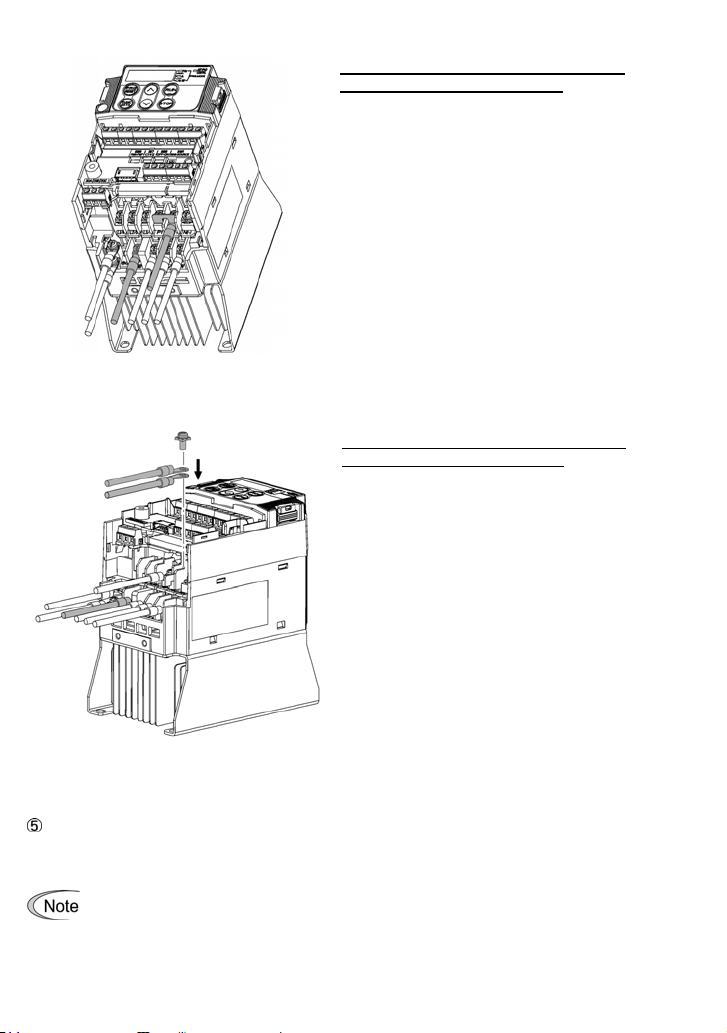
When a DC reactor (DCR) is not connected
together with the braking resistor
1) Remove the screws from terminals P1 and
P(+), together with the jumper bar.
2) Put the wire from terminal P of the braking
resistor and the jumper bar on terminal
P(+) in this order, then secure them with
the screw removed in 1) above.
3) Tighten the screw on terminal P1.
4) Connect the wire from terminal DB of the
braking resistor to the DB of the inverter.
Figure 2.10 Braking Resistor Connection
without DC Reactor (DCR)
When connecting a DC reactor (DCR)
together with the braking resistor
1) Remove the screw from terminal P(+).
2) Overlap the DC reactor (DCR) wire and
braking resistor wire (P) as shown at left
and then secure them to terminal P(+) of
the inverter with the screw.
3) Connect the wire from terminal DB of the
braking resistor to terminal DB of the
inverter.
4) Do not use the jumper bar.
Figure 2.11 Braking Resistor Connection
with DC Reactor (DCR)
DC link bus terminals, P (+) and N (-)
These are provided for the DC link bus powered system. Connect these terminals with terminals P(+)
and N (-) of other inverters.
Consult your Fuji Electric representative if these terminals are to be used.
2-15
Page 38

Main circuit power input terminals, L1/R, L2/S, and L3/T (three-phase input), or L1/L and
L2/N (single-phase input)
1) For safety, make sure that the molded case circuit breaker (MCCB) or magnetic contactor (MC)
is turned off before wiring the main circuit power input terminals.
2) Connect the main circuit power supply wires (L1/R, L2/S and L3/T for three-phase input, or L1/L
and L2/N for single-phase input) to the input terminals of the inverter via an MCCB or
residual-current-operated protective device (RCD)/a ground fault circuit interrupter (GFCI)*, and
MC if necessary.
It is not necessary to align phases of the power supply wires and the input terminals of the
inverter with each other.
* With overcurrent protection
It is recommended that a magnetic contactor be inserted that can be manually activated.
This is to allow you to disconnect the inverter from the power supply in an emergency (e.g.,
when the protective function is activated) so as to prevent a failure or accident from
causing the secondary problems.
2.3.6 Wiring for control circuit terminals
In general, sheaths and covers of the control signal cables and wires are not specifically
designed to withstand a high voltage (i.e., reinforced insulation is not applied). Therefore, if a
control signal cable or wire comes into direct contact with a live conductor of the main circuit, the
insulation of the sheath or the cover might break down, which would expose the signal wire to a
high voltage of the main circuit. Make sure that the control signal cables and wires will not come
into contact with live conductors of the main circuit.
Failure to observe these precautions could cause electric shock and/or an accident.
Noise may be emitted from the inverter, motor and wires.
Take appropriate measure to prevent the nearby sensors and devices from malfunctioning due
to such noise.
An accident could occur.
Table 2.9 lists the symbols, names and functions of the control circuit terminals. The wiring to the
control circuit terminals differs depending upon the setting of the function codes, which reflects the
use of the inverter. Route wires properly to reduce the influence of noise.
2-16
Page 39

Table 2.9 Symbols, Names and Functions of the Control Circuit Terminals
Symbol Name Functions
cation
Classifi-
[13] Power
supply
for the
potentiometer
[12] Analog
setting
voltage
input
Analog
[C1]
setting
current
input
(C1
function)
Analog
Analog input
setting
voltage
input
(V2
function)
PTC
thermistor
input
(PTC
function)
The C1 function, V2 function, or PTC function can be assigned to terminal [C1]. Doing so
requires setting the slide switch on the interface PCB and configuring the related function
code. For details, refer to Section 2.3.7, "Setting up the slide switches".
[11] Analog
common
Power supply (+10 VDC) for frequency command potentiometer
(Potentiometer: 1 to 5k:)
The potentiometer of 1/2 W rating or more should be connected.
(1) The frequency is commanded according to the external analog input
voltage.
• 0 to r10 VDC/0 to r100% (Normal operation)
• r10 to 0 VDC/0 to r100% (Inverse operation)
(2) Inputs setting signal (PID command value) or feedback signal.
(3) Used as additional auxiliary setting to various frequency settings.
• Input impedance: 22k:
• The maximum input is +15 VDC, however, the current larger than
r10 VDC is handled as r10 VDC.
• Inputting a bipolar analog voltage (0 to r10 VDC) to terminal [12]
requires setting function code C35 to "0."
(1) The frequency is commanded according to the external analog input
current.
• 4 to 20 mA DC/0 to 100% (Normal operation)
• 20 to 4 mA DC/0 to 100 % (Inverse operation)
(2) Inputs setting signal (PID command value) or feedback signal.
(3) Used as additional auxiliary setting to various frequency settings.
• Input impedance: 250:
• Maximum input is +30 mA DC, however, the current larger
than +20 mA DC is handled as +20 mA DC.
(1) The frequency is commanded according to the external analog input
voltage.
• 0 to +10 VDC/0 to +100 % (Normal operation)
• +10 to 0 VDC/0 to +100 % (Inverse operation)
(2) Inputs setting signal (PID command value) or feedback signal.
(3) Used as additional auxiliary setting to various frequency settings.
• Input impedance: 22 k:
• Maximum input is +15 VDC, however, the voltage larger
than +10 VDC is handled as +10 VDC.
(1) Connects PTC (Positive
Temperature
Coefficient) thermistor
for motor protection.
The figure shown below
illustrates the internal
circuit diagram. To use
the PTC thermistor, you
must change data of the
function code H26.
Common for analog input/output signals ([13], [12], [C1], and [FM])
Isolated from terminals [CM]s and [CMY].
2-17
Figure 2.12 Internal Circuit Diagram
Page 40

Table 2.9 Symbols, Names and Functions of the Control Circuit Terminals (Continued)
Symbol Name Functions
cation
Classifi-
- Since low level analog signals are handled, these signals are especially susceptible to
the external noise effects. Route the wiring as short as possible (within 66ft (20 m))
and use shielded wires. In principle, ground the shielded sheath of wires; if effects of
external inductive noises are considerable, connection to terminal [11] may be
effective. As shown in Figure 2.13, ground the single end of the shield to enhance the
shield effect.
- Use a twin contact relay for low level signals if the relay is used in the control circuit.
Do not connect the relay's contact to terminal [11].
- When the inverter is connected to an external device outputting the analog signal, a
malfunction may be caused by electric noise generated by the inverter. If this
happens, according to the circumstances, connect a ferrite core (a toroidal core or an
equivalent) to the device outputting the analog signal and/or connect a capacitor
having the good cut-off characteristics for high frequency between control signal wires
as shown in Figure 2.14.
Analog input
- Do not apply a voltage of +7.5 VDC or higher to terminal [C1] when you assign the
terminal [C1] to C1 function. Doing so could damage the internal control circuit.
Figure 2.13 Connection of Shielded Wire Figure 2.14 Example of Electric Noise Reduction
[X1] Digital
input 1
[X2] Digital
input 2
[X3] Digital
input 3
[X4] Digital
input 4
[X5] Digital
input 5
[FWD] Run
Digital input
forward
command
[REV] Run
reverse
command
(1) Various signals such as coast-to-stop, alarm from external equipment,
and multi-frequency commands can be assigned to terminals [X1] to
[X5], [FWD] and [REV] by setting function codes E01 to E05, E98, and
E99. For details, refer to Chapter 5, Section 5.2 "Overview of Function
Codes."
(2) Input mode, i.e. SINK/SOURCE, is changeable by using the internal slide
switch. (Refer to Section 2.3.7, "Setting up the slide switches."
(3) Switches the logic value (1/0) for ON/OFF of the terminals [X1] to [X5],
[FWD], or [REV]. If the logic value for ON of the terminal [X1] is 1 in the
normal logic system, for example, OFF is 1 in the negative logic system
and vice versa.
(4) The negative logic system never applies to the terminals assigned for
FWD and REV.
(Digital input circuit specifications)
Item Min. Max.
Figure 2.15 Digital Input Circuit
Operation
voltage
(SINK)
Operation
voltage
(SOURCE)
Operation current at
ON
(Input voltage is at 0 V)
Allowable leakage
current at OFF
ON level 0 V 2 V
OFF level 22 V 27 V
ON level 22 V 27 V
OFF level 0 V 2 V
2.5 mA 5 mA
- 0.5 mA
2-18
Page 41

Table 2.9 Symbols, Names and Functions of the Control Circuit Terminals (Continued)
Symbol Name Functions
cation
Classifi-
[PLC]
[CM]
PLC
signal
power
Digital
input
common
Using a relay contact to turn [X1], [X2], [X3], [X4], [X5], [FWD], or [REV] ON or OFF
Figure 2.16 shows two examples of a circuit that uses a relay contact to turn control
signal input [X1], [X2], [X3], [X4], [X5], [FWD], or [REV] ON or OFF. In circuit (a), the
slide switch SW1 has been turned to SINK, whereas in circuit (b) it has been turned to
SOURCE.
Note: To configure this kind of circuit, use a highly reliable relay.
Connects to PLC output signal power supply.
(Rated voltage: +24 VDC (Maximum 50 mA DC): Allowable range: +22 to
+27 VDC)
This terminal also supplies a power to the circuitry connected to the
transistor output terminals [Y1] and [Y2]. Refer to "Analog output, pulse
output, transistor output, and relay output terminals" in this Section for more.
Two common terminals for digital input signals
These terminals are electrically isolated from the terminals [11]s and [CMY].
(Recommended product: Fuji control relay Model HH54PW)
(a) With the switch turned to SINK (b) With the switch turned to SOURCE
Digital input
(a) With the switch turned to SINK (b) With the switch turned to SOURCE
For details about the slide switch setting, refer to Section 2.3.7, "Setting up the slide switches".)
Figure 2.16 Circuit Configuration Using a Relay Contact
Using a programmable logic controller (PLC) to turn [X1], [X2], [X3], [X4], [X5],
[FWD], or [REV] ON or OFF
Figure 2.17 shows two examples of a circuit that uses a programmable logic controller
(PLC) to turn control signal input [X1], [X2], [X3], [X4], [X5], [FWD], or [REV] ON or OFF.
In circuit (a), the slide switch SW1 has been turned to SINK, whereas in circuit (b) it has
been turned to SOURCE.
In circuit (a) below, short-circuiting or opening the transistor's open collector circuit in
the PLC using an external power supply turns ON or OFF control signal [X1], [X2], [X3],
[X4], [X5], [FWD], or [REV]. When using this type of circuit, observe the following:
- Connect the + node of the external power supply (which should be isolated from the
PLC's power) to terminal [PLC] of the inverter.
- Do not connect terminal [CM] of the inverter to the common terminal of the PLC.
Figure 2.17 Circuit Configuration Using a PLC
2-19
Page 42

Table 2.9 Symbols, Names and Functions of the Control Circuit Terminals (Continued)
Symbol
cation
Classifi-
[FM]
Analog output
Pulse output
Name Functions
Analog
monitor
(FMA
function)
Pulse
monitor
(FMP
function)
The monitor signal for analog DC voltage (0 to +10 V) is output. You can
select FMA function with slide switch SW6 on the interface PCB, and change
the data of the function code F29.
You can also select the signal functions following with function code F31.
• Output frequency 1 (Before slip compensation)
• Output frequency 2 (After slip compensation)
• Output current • Output voltage • Output torque
• Load factor • Input power • PID feedback amount (PV)
• PG feedback value • DC link bus voltage • Universal AO
• Motor output • Calibration • PID command (SV)
• PID output (MV)
* Input impedance of external device:
Min. 5k: (0 to +10 VDC output)
* While the terminal is outputting 0 to +10 VDC, it is capable to drive up to
two meters with 10k: impedance.
(Adjustable range of the gain: 0 to 300%)
Pulse signal is output. You can select FMP function with the slide switch
SW6 on the interface PCB, and change the data of the function code F29.
You can also select the signal functions following with function code F31.
* Input impedance of the external device: Min. 5k:
* Pulse duty: Approx. 50%
Pulse rate: 25 to 6000 p/s
Voltage waveform
• Pulse output waveform
• FM output circuit
[11]
Analog
common
Do not connect a meter with pull-up resistor to the input (primary) side.
Two common terminals for analog input and output signal terminals
These terminals are electrically isolated from terminals [CM]s and [CMY].
2-20
Page 43

Table 2.9 Symbols, Names and Functions of the Control Circuit Terminals (Continued)
Symbol
cation
Classifi-
[Y1]
[Y2]
Transistor output
[CMY]
Name Functions
Transistor
output 1
Transistor
output 2
Transistor
output
common
Connecting Programmable Logic Controller (PLC) to Terminal [Y1] or [Y2]
Figure 2.19 shows two examples of circuit connection between the transistor output of the
inverter’s control circuit and a PLC. In example (a), the input circuit of the PLC serves as a
SINK for the control circuit output, whereas in example (b), it serves as a SOURCE for the
output.
(1) Various signals such as inverter running, speed/freq. arrival and
overload early warning can be assigned to any terminals, [Y1] and [Y2]
by setting function code E20 and E21. Refer to Chapter 5, Section 5.2
"Overview of Function Codes" for details.
(2) Switches the logic value (1/0) for ON/OFF of the terminals between [Y1],
[Y2], and [CMY]. If the logic value for ON between [Y1], [Y2], and [CMY]
is 1 in the normal logic system, for example, OFF is 1 in the negative
logic system and vice versa.
(Transistor output circuit specification)
Item Max.
Operation
Figure 2.18 Transistor Output Circuit
Figure 2.19 shows examples of connection between the control circuit and a
PLC.
Common terminal for transistor output signal terminals
This terminal is electrically isolated from terminals, [CM]s and [11]s.
• When a transistor output drives a control relay, connect a
surge-absorbing diode across relay’s coil terminals.
• When any equipment or device connected to the transistor
output needs to be supplied with DC power, feed the power
(+24 VDC: allowable range: +22 to +27 VDC, 50 mA max.)
through the [PLC] terminal. Short-circuit between the
terminals [CMY] and [CM] in this case.
ON level
voltage
OFF level
Maximum motor
current at ON
Leakage current
at OFF
3 V
27 V
50 mA
0.1 mA
(a) PLC serving as SINK (b) PLC serving as SOURCE
Figure 2.19 Connecting PLC to Control Circuit
2-21
Page 44

Table 2.9 Symbols, Names and Functions of the Control Circuit Terminals (Continued)
Symbol Name Functions
cation
Classifi-
[30A/B/C]Alarm
Relay output
RJ-45
connect
or for
the
keypad
relay
output
(for any
error)
Standard
RJ-45
connector
(1) Outputs a contact signal (SPDT) when a protective function has been
activated to stop the motor.
Contact rating:
250 VAC, 0.3A, cos I = 0.3, 48 VDC, 0.5A
(2) Any one of output signals assigned to terminals [Y1] and [Y2] can also
be assigned to this relay contact to use it for signal output.
(3) Switching of the normal/negative logic output is applicable to the
following two contact output modes: "Between terminals [30A] and
[30C] is closed (excited) for ON signal output (Active ON)" or "Between
terminals [30A] and [30C] is open (non-excited) for ON signal output
(Active OFF).
(1) Used to connect the inverter with the keypad. The inverter supplies
the power to the keypad through the pins specified below. The
extension cable for remote operation also uses wires connected to
these pins for supplying the keypad power.
(2) Remove the keypad from the standard RJ-45 connector, and connect
the RS-485 communications cable to control the inverter through the
PC or PLC (Programmable Logic Controller). Refer to Section 2.3.7,
"Setting up the slide switches" for setting of the terminating resistor.
Communication
Figure 2.20 RJ-45 Connector and its Pin Assignment*
* Pins 1, 2, 7, and 8 are exclusively assigned to power lines for the
standard keypad and multi-function keypad, so do not use those
• Route the wiring of the control circuit terminals as far from the wiring of the main circuit as
possible. Otherwise electric noise may cause malfunctions.
• Fix the control circuit wires inside the inverter to keep them away from the live parts of the
main circuit (such as the terminal block of the main circuit).
• The RJ-45 connector pin assignment on the FRENIC-Multi series is different from that on
the FVR-E11S series. Do not connect to the keypad of the FVR-E11S series of inverter.
Doing so could damage the internal control circuit.
Mounting the interface printed circuit board (interface PCB)
• Usually, you do not need to remove the interface PCB. However, if you remove the interface
PCB, be sure to mount the interface PCB by putting hooks provided on the interface PCB
into the inverter until you have heard click sound.
pins for any other equipment.
Figure 2.21 Mounting the Interface Printed Circuit Board (Interface PCB)
2-22
Page 45

2.3.7 Setting up the slide switches
Before changing the switches, turn OFF the power and wait more than five minutes. Make sure
that the LED monitor is turned OFF. Further, make sure, using a circuit tester or a similar
instrument, that the DC link bus voltage between the terminals P (+) and N (-) has dropped below
the safe voltage (+25 VDC).
An electric shock may result if this warning is not heeded as there may be some residual
electric charge in the DC bus capacitor even after the power has been turned OFF.
Switching the slide switches
Switching the slide switches with excessive power, the switches may be damaged.
Switching the slide switches using precision screwdriver, etc. and treat it without damages.
(Do not switching the slide switches with an acute thing such as needles.)
Setting up the slide switches
Switching the slide switches located on the control PCB and interface PCB allows you to customize
the operation mode of the analog output terminals, digital I/O terminals, and communications ports.
The locations of those switches are shown in Figure 2.22.
To access the slide switches, remove the terminal cover and keypad.
For details on how to remove the terminal cover, refer to Section 2.3.1, "Removing the terminal
cover and main circuit terminal block cover."
Table 2.10 lists function of each slide switch.
Table 2.10 Function of Each Slide Switch
Switch Function
Switches the service mode of the digital input terminals between SINK and SOURCE.
SW1
ƒ To make the digital input terminal [X1] to [X5], [FWD] or [REV] serve as a current sink, turn
SW1 to the SINK position.
ƒ To make them serve as a current source, turn SW1 to the SOURCE position.
SW3 Switches the terminating resistor of RS-485 communications port on the inverter on and off.
ƒ To connect a keypad to the inverter, turn SW3 to OFF. (Factory default)
ƒ If the inverter is connected to the RS-485 communications network as a terminating
device, turn SW3 to ON.
Switches the output mode of the output terminal [FM] between analog voltage and pulse
SW6
output.
When changing this switch setting, also change the data of function code F29.
SW6 Data for F29
Analog voltage output
(Factory default)
Current output FMP 2
Switches property of the input terminal [C1] for C1, V2, or PTC.
SW7
When changing this switch setting, also change the data of function code E59 and H26.
SW8
Analog frequency setting in current
(Factory default)
Analog frequency setting in voltage V2 OFF 1 0
PTC thermistor input C1 ON 0 1
FMA 0
Data for
SW7 SW8
C1 OFF 0 0
E59
Data for
H26
2-23
Page 46

Figure 2.22 shows the location of slide switches for the input/output terminal configuration.
Switching example
SW3
OFF ON
Factory
default
SW6
FMA
Factory
default
FMP
-
Figure 2.22 Location of the Slide Switches
SW7 SW8
C1 OFF SINK
V2 ON SOURCE
SW1*
2-24
Page 47

2.4 Mounting and Connecting a Keypad
2.4.1 Mounting style and parts needed for connection
(1) Mounting style
You can mount a keypad in any style described below.
Mounting a keypad on the panel wall (Refer to Figure 2.23.)
Installing a keypad at a remote site (e.g. for operation on hand) (Refer to Figure 2.24.)
Figure 2.23 Mounting Keypad on the Panel Wall
Figure 2.24 Installing Keypad at a Remote Site (e.g. for Operation on Hand)
2-25
Page 48

(2) Parts needed for connection
To mount/install a keypad on a place other than an inverter, parts listed below are needed.
Parts name Model Remarks
Extension cable (Note) CB-5S, CB-3S and CB-1S
Fixing screw M3 u 16
Keypad rear cover
(Note) When using an off-the-shelf LAN cable, use a 10BASE-T/100BASE-TX straight type cable
compliant to US ANSI TIA/EIA-568A Category 5. (Less than 66ft(20m))
Recommended LAN cable
Manufacturer: SANWA Supply Co., LTD.
Model: KB-10T5-01K (3.3ft(1m))
KB-STP-01K (3.3ft(1m)) (Shielded LAN cable compliant to EMC Directive)
3 cables available in length of 16ft (5m), 9.8ft
(3m), and 3.3ft (1m).
Accessories
Accessories
2.4.2 Mounting/installing steps
Mounting a keypad on the panel wall
Pull the keypad toward you while holding down the hooks on the keypad.
Fix the keypad rear cover to the keypad.
Figure 2.26 Fixing the Keypad Rear Cover for Remote Keypad Operation
Figure 2.25 Removing a Keypad
2-26
Page 49

Make a cut-out on the panel wall. For details, refer to Chapter 8, Section 8.4.2 "Standard
keypad."
To mount the keypad on the panel, fix it firmly using a pair of M3 screws put through the
taps shown below. (Figure 2.27.)
(Tightening torque: 6.2 Ib-in (0.7 Nm))
Figure 2.27 Mounting a Keypad on the Panel Wall
Connect an extension cable (CB-5S, CB-3S or CB-1S) or off-the-shelf straight LAN cable
to RJ-45 connectors (Modular jacks) on the keypad and inverter (standard RS-485 port.)
(Refer to Figure 2.28)
Installing a keypad at a remote site (e.g. for operation on hand)
Follow the step
Figure 2.28 Connecting a Keypad and an Inverter’s Standard RS-485 port
in Mounting a keypad on the panel wall.
2-27
Page 50

2.5 Cautions Relating to Harmonic Component, Noise, and Leakage Current
(1) Harmonic component
Input current to an inverter includes a harmonic component, which may affect other loads and power
factor correcting capacitors that are connected to the same power supply as the inverter. If the
harmonic component causes any problems, connect a DC reactor (option) to the inverter. It may also
be necessary to connect an AC reactor to the power factor correcting capacitors.
(2) Noise
If noise generated from the inverter affects other devices, or that generated from peripheral
equipment causes the inverter to malfunction, follow the basic measures outlined below.
1) If noise generated from the inverter affects the other devices through power wires or grounding
wires:
- Isolate the grounded metal frames of the inverter from those of the other devices.
- Connect a noise filter to the inverter power wires.
- Isolate the power system of the other devises from that of the inverter with an insulated
transformer.
2) If induction or radio noise generated from the inverter affects other devices through power wires
or grounding wires:
- Isolate the main circuit wires from the control circuit wires and other device wires.
- Put the main circuit wires through a metal conduit pipe, and connect the pipe to the ground
near the inverter.
- Install the inverter into the metal switchboard and connect the whole board to the ground.
- Connect a noise filter to the inverter power wires.
3) When implementing measures against noise generated from peripheral equipment:
- For the control signal wires, use twisted or shielded-twisted wires. When using
shielded-twisted wires, connect the shield of the shielded wires to the common terminals of
the control circuit or ground.
- Connect a surge absorber in parallel with magnetic contactor's coils or other solenoids (if any).
(3) Leakage current
A high frequency current component generated by insulated gate bipolar transistors (IGBTs)
switching ON/OFF inside the inverter becomes leakage current through stray capacitance of inverter
input and output wires or a motor. If any of the problems listed below occur, take an appropriate
measure against them.
Table 2.11 Leakage Current Countermeasures
Problem Measures
A residual-current-operated
protective device (RCD) or a
ground fault circuit
interrupter (GFCI) that is
connected to the input
(primary) side has tripped.
An external thermal relay
was activated.
1) Decrease the carrier frequency.
2) Make the wires between the inverter and motor shorter.
3) Use an RCD or GFCI with lower sensitivity than the one currently
used.
4) Use an RCD or GFCI that features measures against the high
frequency current component (Fuji SG and EG series).
1) Decrease the carrier frequency.
2) Increase the settling current of the thermal relay.
3) Use the electronic thermal overload protection built in the inverter,
instead of the external thermal relay.
2-28
Page 51

Chapter 3 OPERATION USING THE KEYPAD
3.1 LED Monitor, Keys and LED Indicators on the Keypad
As shown at the right, the keypad
consists of a four-digit LED monitor,
six keys, and five LED indicators.
The keypad allows you to run and
stop the motor, monitor running
status, and switch to the menu mode.
In the menu mode, you can set the
function code data, monitor I/O signal
states, maintenance information, and
alarm information.
Table 3.1 Overview of Keypad Functions
Item
LED
Monitor
LED Monitor,
Keys, and LED
Indicators
Four-digit, 7-segment LED monitor which displays the followings
according to the operation modes.
In Running mode: Running status information (e.g., output
In Programming mode: Menus, function codes and their data
In Alarm mode: Alarm code, which identifies the alarm factor if
Program/Reset key which switches the operation modes of the inverter.
In Running mode: Pressing this key switches the inverter to
In Programming mode: Pressing this key switches the inverter to
In Alarm mode: Pressing this key after removing the alarm
Function/Data key which switches the operation you want to do in each
mode as follows:
In Running mode: Pressing this key switches the information to
Operation
Keys
In Programming mode: Pressing this key displays the function code
In Alarm mode: Pressing this key displays the details of the
RUN key. Press this key to run the motor.
STOP key. Press this key to stop the motor.
and
UP and DOWN keys. Press these keys to select the setting items and
change the function code data displayed on the LED monitor.
Program/
Reset key
Function/
Data key
7-segment LED
monitor
UP key
Functions
frequency, current, and voltage)
the protective function is activated.
Programming mode.
Running mode.
factor will switch the inverter to Running
mode.
be displayed concerning the status of the
inverter (output frequency (Hz), output current
(A), output voltage (V), etc.).
and sets the data entered with
keys.
problem indicated by the alarm code that has
come up on the LED monitor.
DOWN key
LED
indicators
RUN key
RUN LED
STOP
key
and
3-1
Page 52

Table 3.1 Overview of Keypad Functions (Continued)
Item
LED
Indicators
LED Monitor,
Keys, and LED
Indicators
RUN LED
KEYPAD
CONTROL LED
Unit LEDs
(3 LEDs)
Functions
Lights when any run command to the inverter is active.
Lights when the inverter is ready to run with a run command entered by
the
key (F02 = 0, 2, or 3). In Programming and Alarm modes, you
cannot run the inverter even if the indicator lights.
These three LED indicators identify the unit of numeral displayed on the
LED monitor in Running mode by combination of lit and unlit states of
them.
Unit: kW, A, Hz, r/min and m/min
Refer to Chapter 3, Section 3.3.1 "Monitoring the running status" for
details.
While the inverter is in Programming mode, the LEDs of
Hz and kW light.
Hz
A
kW
Simultaneous keying
Simultaneous keying means pressing two keys at the same time. The FRENIC-Multi supports
simultaneous keying as listed below. The simultaneous keying operation is expressed by a "+" letter
between the keys throughout this manual.
(For example, the expression "
key.)
Operation mode Simultaneous keying Used to:
+ keys" stands for pressing the key while holding down the
Table 3.2 Simultaneous Keying
Programming
mode
Alarm mode + keys
+ keys
+ keys
Change certain function code data. (Refer to
codes F00, H03, H45, H97, J75, and J77 in
Chapter 5 "FUNCTION CODES.")
Switch to Programming mode without resetting
alarms currently occurred.
3.2 Overview of Operation Modes
FRENIC-Multi features the following three operation modes:
Running mode : This mode allows you to enter run/stop commands in regular operation.
Programming mode : This mode allows you to configure function code data and check a variety
Alarm mode : If an alarm condition arises, the inverter automatically enters Alarm mode.
* Alarm code: Indicates the cause of the alarm condition that has triggered a protective function. For details,
refer to Chapter 8, Section 8.5 "Protective Functions."
You can also monitor the running status in real time.
of information relating to the inverter status and maintenance.
In this mode, you can view the corresponding alarm code* and its related
information on the LED monitor.
3-2
Page 53

Figure 3.1 shows the status transition of the inverter between these three operation modes.
(*1) The speed monitor allows you to select the desired one from the seven speed monitor items by using
function code E48.
(*2) Applicable only when PID control is active (J01 = 1, 2 or 3).
(*3) The Timer screen appears only when the timer operation is enabled with function code C21.
(*4) Applicable only when the full-menu mode is selected (E52 = 2).
(*5) Pressing
key can reset an alarm only when the latest alarm is displayed on the LED monitor.
Figure 3.1 Transition between Basic Screens in Individual Operation Mode
3-3
Page 54

3.3 Running Mode
When the inverter is turned ON, it automatically enters Running mode in which you can:
(1) Monitor the running status (e.g., output frequency and output current),
(2) Configure the reference frequency and other settings,
(3) Run/stop the motor, and
(4) Jog (inch) the motor.
3.3.1 Monitoring the running status
In Running mode, the eleven items listed below can be monitored. Immediately after the inverter is
turned ON, the monitor item specified by function code E43 is displayed. Press the
between monitor items. For details of switching the monitor item by using the
"Monitor of running status" in Running mode in Figure 3.1.
Table 3.3 Monitoring Items
Monitor items
Speed monitor
Output frequency
(before slip
compensation)
Output frequency
(after slip
compensation)
Reference
frequency
Motor speed
Load shaft speed
Line speed
Constant feeding
rate time
Output current
Output voltage *
Calculated torque
Input power
Display
sample on
the LED
monitor *
Function code E48 specifies what to be displayed on the LED monitor
and LED indicators.
2
W
LED indicator
: ON, : OFF
1
Hz A kW Hz Frequency actually being output (E48 = 0)
Hz A kW Hz Frequency actually being output (E48 = 1)
Hz A kW Hz Reference frequency being set (E48 = 2)
Hz A kW r/min
Hz A kW r/min Output frequency (Hz) u E50 (E48 = 4)
Hz A kW m/min Output frequency (Hz) u E50 (E48 = 5)
Hz A kW min
Hz A kW A
Hz A kW V
Hz A kW %
Hz A kW kW Input power to the inverter 9
Unit Meaning of displayed value
For motor 2, read P01 as A15.
E50
Current output from the inverter
in RMS
Voltage output from the inverter
in RMS
Motor output torque in %
(Calculated value)
120
×(Hz)frequencyOutput
P01
E39×(Hz)frequencyOutput
key to switch
key, refer to
Function
code data
for E43
0
(E48 = 3)
(E48 = 6)
3
4
8
3-4
Page 55

Table 3.3 Monitoring Items (Continued)
Display
3
, *
sample on
monitor *
4
5
3
4
6
7
the LED
Monitor items
PID command
*
PID feedback
amount *3, *
Timer
(Timer operation) *
PID output *3, *
Load factor *
Motor output *
LED indicator
: ON, : OFF
1
Hz A kW 㧙 10
Hz A kW 㧙
Hz A kW min
Hz A kW %
Hz A kW %
Hz A kW kW Motor output in kW 16
Unit
Meaning of displayed value
PID command/feedback amount
transformed to that of virtual
physical value of the object to be
controlled (e.g. temperature)
Refer to function codes E40 and
E41 for details.
Remaining time of timer operation
PID output in % as the
maximum frequency (F03)
being at 100%
For motor 2, read F03 as A01.
Load factor of the motor in % as
the rated output being at 100%
Function
code E43
12
13
14
15
*1 A value exceeding 9999 cannot be displayed on the 4-digit LED monitor screen, so " "
appear instead.
W
*2 When the LED monitor displays an output voltage, the 7-segment letter
in the lowest digit
stands for the unit of the voltage "V."
*3 These PID related items appear only when the inverter PID-controls the motor according to a
PID command specified by function code J01 (= 1, 2 or 3).
The Timer item appears only when the timer operation is enabled with function code C21.
When the PID control or timer operation is disabled, "----" appear.
*4 When the LED monitor displays a PID command or its output amount, the dot (decimal point)
attached to the lowest digit of the 7-segment letter blinks.
*5 When the LED monitor displays a PID feedback amount, the dot (decimal point) attached to the
lowest digit of the 7-segment letter lights.
*6 When the LED monitor displays a load factor, the 7-segment letter
in the lowest digit stands for
"%."
*7 When the LED monitor displays the motor output, the unit LED indicator "kW" blinks.
3-5
Page 56

3.3.2 Setting up frequency and PID commands
You can set up the desired frequency and PID commands by using
and keys on the keypad. It
is also possible to set up the frequency command as load shaft speed, motor speed etc. by setting
function code E48.
Setting up a frequency command
and keys (Factory default)
Using
(1) Set function code F01 to "0: / keys on keypad." This can be done only when the inverter is
in Running mode.
(2) Press the
(3) If you need to change the frequency command, press the
/ key to display the current reference frequency. The lowest digit will blink.
/ key again. The new setting
will be automatically saved into the inverter's internal memory and retained even when the
power is off. When the power is turned ON next time, the setting will be used as an initial
reference frequency.
• If you have set function code F01 to "0: / keys on keypad" but have selected a
frequency command source other than frequency command 1 (i.e., frequency command
2, frequency command via communication, or multi-frequency command), then the
and keys are disabled to change the current frequency command even in Running
mode. Pressing either of these keys just displays the current reference frequency.
• When you start specifying the reference frequency or any other parameter with the
key, the least significant digit on the display blinks; that is, the cursor lies in the least
significant digit. Holding down the
/ key changes data in the least significant digit
and generates a carry, while the cursor remains in the least significant digit.
• After the least significant digit blinks by pressing the
/ key, holding down the
key for more than 1 second moves the cursor from the least significant digit to the most
significant digit. Further holding it down moves the cursor to the next lower digit. This
cursor movement allows you to easily move the cursor to the desired digit and change
the data in higher digits.
• By setting function code C30 to "0:
/ keys on keypad" and selecting frequency
command 2, you can also specify or change the frequency command in the same
manner using the
/ key.
You can set a reference frequency not only with the frequency (Hz) but also with other menu items
(motor speed, load shaft speed, line speed and constant feeding rate time) depending on the setting
of function code E48 (= 3, 4, 5 or 6) as listed in Table 3.3.
/
3-6
Page 57
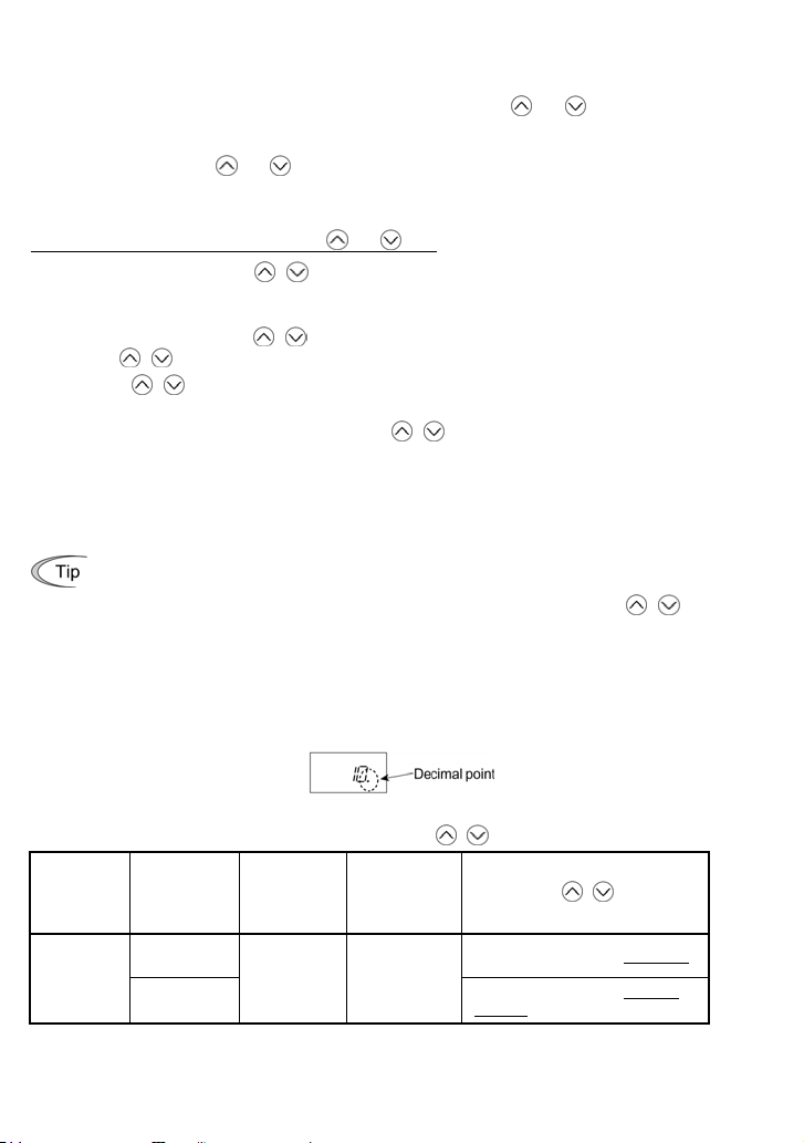
Settings under PID process control
y
To enable the PID process control, you need to set function code J01 to "1" or "2."
Under the PID control, the items that can be specified or checked with
and keys are different
from those under regular frequency control, depending upon the current LED monitor setting. If the
LED monitor is set to the speed monitor (E43 = 0), you can access manual speed commands
(frequency command) with
and keys; if it is set to any other, you can access the PID process
command with those keys.
Refer to the FRENIC-Multi User's Manual for the details of the PID control.
Setting the PID process command with the
(1) Set function code J02 to "0: / keys on keypad."
(2) Set the LED monitor to something other than the speed monitor (E43=0) when the inverter is in
Running mode. When the keypad is in Programming or Alarm mode, you cannot modify the PID
process command with the
with the
(3) Press the
/ key, first switch to Running mode.
/ key to display the PID process command. The lowest digit of the displayed
/ key. To enable the PID process command to be modified
command and its decimal point blink.
(4) To change the PID process command, press the
you have specified will be automatically saved into the inverter’s internal memory. It is retained
even if you temporarily switch to another PID process command source and then go back to the
via-keypad PID process command. Also, it is retained in the memory even while the inverter is
powered off, and will be used as the initial PID process command next time the inverter is
powered ON.
• Even if multi-frequency is selected as a PID process command (SS4 or SS8 = ON), you
still can set the process command using the keypad.
• When function code J02 is set to any value other than "0," pressing the
displays, on the 7-segment LED monitor, the PID process command currently selected,
while you cannot change the setting.
• On the 7-segment LED monitor, the decimal point of the lowest digit is used to
characterize what is displayed. The decimal point of the lowest digit blinks when a PID
process command is displayed; the decimal point lights when a PID feedback amount is
displayed.
and keys
/ key again. The PID process command
/ ke
PID control
(Mode
selection)
J01
Table 3.4 PID process Command Manually Set with / Key and Requirements
PID control
1 or 2
(Remote
command SV)
J02
0
Other than 0
LED monitor
E43
Other than 0 ON or OFF
Multi-frequency
SS4, SS8
3-7
With
PID process command by keypad
PID process command currently
selected
/ key
Page 58

Setting up the frequency command with and keys under PID process control
When function code F01 is set to "0" ( / keys on keypad) and frequency command 1 is
selected as a manual speed command (when disabling the frequency setting command via
communications link or multi-frequency command), switching the LED monitor to the speed monitor
in Running mode enables you to modify the frequency command with the
In Programming or Alarm mode, the
keys are disabled to modify the frequency command.
/
/ keys.
You need to switch to Running mode.
Table 3.5 lists the combinations of the commands and the figure illustrates how the manual speed
command
entered via the keypad is translated to the final frequency command .
The setting procedure is the same as that for setting of a usual frequency command.
Table 3.5 Manual Speed (Frequency) Command Specified with / Keys and Requirements
PID control
(Mode
selection)
J01
1 or 2 0
LED
monitor
E43
Frequency
command 1
F01
Multifrequency
SS2
0 OFF OFF OFF
Other than the above
Multifrequency
SS1
Communications
link
operation
LE
Cancel PID
control
Hz/PID
OFF
(PID
enabled)
ON
(PID
disabled)
OFF
(PID
enabled)
ON
(PID
disabled)
Pressing
keys controls:
PID output
(as final frequency
command)
Manual speed
(frequency)
command set by
keypad
PID output
(as final frequency
command)
Manual speed
(frequency)
command currently
selected
/
3-8
Page 59

Settings under PID dancer control
y
To enable the PID dancer control, you need to set function code J01 to "3."
Under the PID control, the items that can be specified or checked with
and keys are different
from those under the regular frequency control, depending upon the current LED monitor setting. If
the LED monitor is set to the speed monitor (E43 = 0), the item accessible is the primary frequency
command; if it is set to any other data, it is the PID dancer position command.
Refer to the FRENIC-Multi User's Manual for the details of the PID control.
Setting the PID dancer position command with the
(1) Set function code J02 to "0:
/ keys on keypad."
and keys
(2) Set the LED monitor to something other than the speed monitor (E43=0) when the inverter is in
Running mode. When the keypad is in Programming or Alarm mode, you cannot modify the PID
command with the
/ key, first switch to Running mode.
the
(3) Press the
/ key. To enable the PID dancer position command to be modified with
/ key to display the PID dancer position command. The lowest digit of the
displayed command and its decimal point blink.
(4) To change the command, press the
/ key again. The command you have specified will be
automatically saved into the inverter’s internal memory as function code J57 data. It is retained
even if you temporarily switch to another PID command source and then go back to the
via-keypad PID command. Furthermore, you can directly configure the command with function
code J57.
• Even if multi-frequency is selected as a PID command (SS4 or SS8 = ON), you still can
set the PID dancer position command using the keypad.
• When function code J02 is set to any value other than "0," pressing the
/ ke
displays, on the 7-segment LED monitor, the PID command currently selected, while you
cannot change the setting.
• On the 7-segment LED monitor, the decimal point of the lowest digit is used to
characterize what is displayed. The decimal point of the lowest digit blinks when a PID
command is displayed; the decimal point lights when a PID feedback amount is
displayed.
PID control
(Mode
selection)
J01
Table 3.6 PID Command Manually Set with / Key and Requirements
3
PID control
(Remote
command SV)
J02
0
Other than 0
LED monitor
E43
Other than 0 ON or OFF
Multi-frequency
SS4, SS8
3-9
PID command by keypad
PID command currently selected
With
/ key
Page 60

Setting up the primary frequency command with and keys under PID dancer control
When function code F01 is set to "0" ( /
keys on keypad) and frequency command 1 is
selected as a primary frequency command (when disabling the frequency setting command via
communications link and multi-frequency command), switching the LED monitor to the speed
monitor in Running mode enables you to modify the frequency command with the
In Programming or Alarm mode, the
/ keys are disabled to modify the frequency command.
keys.
/
You need to switch to Running mode.
Table 3.7 lists the combinations of the commands and the figure illustrates how the primary
frequency command
entered via the keypad is translated to the final frequency command .
The setting procedure is the same as that for setting of a usual frequency command.
Table 3.7 Primary Frequency Command Specified with / Keys and Requirements
PID control
(Mode
selection)
J01
LED
monitor
E43
3 0
Frequency
command
1 F01
Multifrequency
SS2
0 OFF OFF OFF
Other than the above
Multifrequency
SS1
Communications
link
operation
LE
Cancel PID
control
Hz/PID
OFF
(PID
enabled)
ON
(PID
disabled)
OFF
(PID
enabled)
ON
(PID
disabled)
Pressing
keys controls:
Final frequency
command modified
by PID output
Keypad primary
command
(Frequency)
Final frequency
command modified
by PID output
Current primary
command
(Frequency)
/
3-10
Page 61

3.3.3 Running/stopping the motor
t
By factory default, pressing the
key starts
running the motor in the forward direction and
pressing the
stop. The
key decelerates the motor to
key is enabled only in Running
mode.
The motor rotational direction can be selected
by changing the setting of function code F02.
Operational relationship between function code F02 (Operation method) and key
Table 3.8 lists the relationship between function code F02 settings and the
key, which determines
the motor rotational direction.
Table 3.8 Motor Rotational Direction Specified by F02
Data for F02
0
1
2 In the forward direction
3 In the reverse direction
Pressing the
In the direction commanded by the
terminal [FWD] or [REV]
key disabled
(The motor is driven by terminal
[FWD] or [REV] command.)
key runs the motor:
(Note) The rotational direction of
IEC-compliant motors is opposite
to that of the motor shown here.
For the details on operations with function code F02, refer to Chapter 5 "FUNCTION CODES."
When the keypad is in use for specifying the frequency settings or driving the motor, do no
disconnect the keypad from the inverter when the motor is running. Doing so may stop the
inverter.
3.4 Programming Mode
The Programming mode provides you with these functions--setting and checking function code data,
monitoring maintenance information and checking input/output (I/O) signal status. The functions can
be easily selected with the menu-driven system. Table 3.9 lists menus available in Programming
mode. The leftmost digit (numerals) of each letter string on the LED monitor indicates the
corresponding menu number and the remaining three digits indicate the menu contents.
When the inverter enters Programming mode from the second time on, the menu selected last in
Programming mode will be displayed.
3-11
Page 62

Table 3.9 Menus Available in Programming Mode
LED
Menu # Menu
0 "Quick Setup"
1 "Data Setting"
2 "Data Checking"
3 "Drive Monitoring"
4 "I/O Checking"
"Maintenance
5
Information"
6 "Alarm Information"
(Note 1) Mounting an optional multi-function keypad (TP-G1) adds the data copying function to the menu,
enabling reading, writing, and verifying of function code data.
(Note 2) The o codes are displayed only when the corresponding option is mounted. For details, refer to the
Instruction Manual for the corresponding option.
monitor
shows:
HP
HAA
GAA
EAA
RAA
JAA
CAA
LAA
[AA
QAA
TGR
QRG
KAQ
EJG
CN
Main functions
Displays only basic function codes to customize
the inverter operation.
F codes
(Fundamental functions)
E codes
(Extension terminal functions)
C codes
(Control functions)
P codes
(Motor 1 parameters)
H codes
(High performance functions)
A codes
(Motor 2 parameters)
J codes
(Application functions)
y codes (Link functions)
o codes (Optional function)
Displays only function codes that have been
changed from their factory defaults. You can refer
to or change those function code data.
Displays the running information required for
maintenance or test running.
Displays external interface information.
Displays maintenance information including
cumulative run time.
Displays the recent four alarm codes. You can
refer to the running information at the time when
the alarm occurred.
Selecting each of
these function
codes enables
its data to be
displayed/changed.
Refer
to:
Section
3.4.1
Section
3.4.2
Section
3.4.3
Section
3.4.4
Section
3.4.5
Section
3.4.6
Section
3.4.7
Selecting menus to display
The menu-driven system allows you to cycle through menus. To cycle through necessary menus
only for simple operation, use function code E52 that provides a choice of three display modes as
listed below.
The factory default (E52 = 0) is to display only two menus--Menu #0 "Quick Setup" and Menu #1
"Data Setting," allowing no switching to any other menu.
Table 3.10 Keypad Display Mode Selection – Function Code E52
Data for E52 Mode Menus selectable
0 Function code data editing mode (factory default)
1 Function code data check mode Menu #2 "Data Checking"
2 Full-menu mode Menus #0 through #6
Menu #0 "Quick Setup"
Menu #1 "Data Setting"
Pressing the / key will cycle through the menu. With the key, you can select the
desired menu item. Once the entire menu has been cycled through, the display will return
to the first menu item.
3-12
Page 63

3.4.1 Setting up basic function codes quickly -- Menu #0 "Quick Setup" --
Menu #0 "Quick Setup" in Programming mode allows you to quickly display and set up a basic set of
function codes specified in Chapter 5, Section 5.1, "Function Code Tables."
To use Menu #0 "Quick Setup," you need to set function code E52 to "0" (Function code data editing
mode) or "2" (Full-menu mode).
The predefined set of function codes that are subject to quick setup are held in the inverter.
Listed below are the function codes (including those not subject to quick setup) available on the
FRENIC-Multi.
Table 3.11 Function Codes Available on FRENIC-Multi
Function code
group
F codes F00 to F51
E codes E01 to E99
C codes C01 to C53 Control functions
P codes P01 to P99 Motor 1 parameters
H codes H03 to H98
A codes A01 to A46 Motor 2 parameters
J codes J01 to J92
y codes y01 to y99 Link functions Functions for controlling communication
o codes o01 to o59 Optional functions Functions for options (Note)
(Note) The o codes are displayed only when the corresponding option is mounted. For details of the o codes,
refer to the Instruction Manual for the corresponding option.
Function codes Function Description
Fundamental
functions
Extension terminal
functions
High performance
functions
Application
functions
Functions concerning basic motor running
Functions concerning the assignment of
control circuit terminals
Functions concerning the display of the LED
monitor
Functions associated with frequency
settings
Functions for setting up characteristics
parameters (such as capacity) of the motor
Highly added-value functions
Functions for sophisticated control
Functions for setting up characteristics
parameters (such as capacity) of the motor
Functions for applications such as PID
control
For the list of function codes subject to quick setup and their descriptions, refer to Chapter 5,
Section 5.1 "Function Code Tables."
Through a multi-function keypad, you can add or delete function codes that are subject to
Quick Setup. For details, refer to the "Multi-function Keypad Instruction Manual."
Once you have added or deleted function codes for Quick Setup through a multi-function
keypad, they will remain valid even after you switch to a standard keypad. To restore the
function code settings subject to Quick Setup to their factory defaults, initialize the whole
data using function code H03 (data = 1).
3-13
Page 64

Figure 3.2 shows the menu transition in Menu #0 "Quick Setup."
Figure 3.2 Menu Transition in Menu #0 "Quick Setup"
Basic key operation
This section gives a description of the basic key operation, following the example of the function
code data changing procedure shown in Figure 3.3.
This example shows you how to change function code F01 data from the factory default "
keys on keypad (F01 = 0)" to "Current input to terminal [C1] (C1 function) (4 to 20 mA DC) (F01 = 2)."
(1) Turn the inverter ON. It automatically enters Running mode. In that mode, press the
switch to Programming mode. The function selection menu appears. (In this example,
displayed.)
(2) If anything other than
(3) Press the
(4) Use the
press the
The data of this function code appears. (In this example, data
and keys to display the desired function code (
HP
is displayed, use the and keys to display
key to proceed to a list of function codes.
key.
3-14
H
in this example), then
ofH
appears.)
HP
HP
.
/
key to
is
Page 65

(5) Change the function code data using the and keys. (In this example, press the key
two times to change data
(6) Press the
The
return to the function code list, then move to the next function code. (In this example,
Pressing the
reverts to the previous value, the display returns to the function code list, and the original
function code reappears.
(7) Press the
key to establish the function code data.
UCWG
appears and the data will be saved in the memory inside the inverter. The display will
key to return to the menu from the function code list.
Cursor movement
You can move the cursor when changing function code data by holding down the
for 1 second or longer in the same way as with the frequency settings. This action is called
"Cursor movement."
to .)
H
.)
key instead of the key cancels the change made to the data. The data
key
Figure 3.3 Example of Function Code Data Changing Procedure
3.4.2 Setting up function codes -- Menu #1 "Data Setting" --
Menu #1 "Data Setting" in Programming mode allows you to set up function codes for making the
inverter functions match your needs.
To set function codes in this menu, it is necessary to set function code E52 to "0" (Function code data
editing mode) or "2" (Full-menu mode).
Basic key operation
For details of the basic key operation, refer to Menu #0 "Quick Setup" in Section 3.4.1.
3-15
Page 66

3.4.3 Checking changed function codes -- Menu #2 "Data Checking" --
Menu #2 "Data Checking" in Programming mode allows you to check function codes that have been
changed. Only the function codes whose data has been changed from the factory defaults are
displayed on the LED monitor. You can refer to the function code data and change it again if
necessary. The menu transition in Menu #2 "Data Checking" is as same as its of Menu #0 "Quick
Setup."
Basic key operation
For details of the basic key operation, refer to Menu #0 "Quick Setup" in Section 3.4.1.
To check function codes in Menu #2 "Data Checking," it is necessary to set function code
E52 to "1" (Function code data check mode) or "2" (Full-menu mode).
3.4.4 Monitoring the running status -- Menu #3 "Drive Monitoring" --
Menu #3 "Drive Monitoring" is used to monitor the running status during maintenance and trial
running. The display items for "Drive Monitoring" are listed in Table 3.12. Figure 3.4 shows the menu
transition in Menu #3 "Drive Monitoring."
Figure 3.4 Menu Transition in Menu #3 "Drive Monitoring"
3-16
Page 67

Basic key operation
To monitor the running status on the drive monitor, set function code E52 to "2" (Full-menu mode)
beforehand.
(1) Turn the inverter ON. It automatically enters Running mode. In that mode, press the
key to
switch to Programming mode. The function selection menu appears.
(2) Use the
(3) Press the
(4) Use the
and keys to display "Drive Monitoring" (
key to proceed to a list of monitoring items (e.g.
QRG
).
A
).
and keys to display the desired monitoring item, then press the key.
The running status information for the selected item appears.
(5) Press the
key to return to a list of monitoring items. Press the key again to return to the
menu.
Table 3.12 Drive Monitor Display Items
LED
monitor
shows:
A
A
A
A
A
A
A
A
A
A
A
A
A
A
Item Unit Description
Output
frequency
Output
frequency
Output current
Output voltage
Calculated
torque
Reference
frequency
Rotational
direction
Running
status
Motor speed
Load shaft
speed
or
Line speed
PID command
PID feedback
amount
Torque limit
value
Torque limit
value
Hz
Output frequency before slip compensation
Hz
Output frequency after slip compensation
Output current
A
Output voltage
V
%
Calculated output torque of the motor in %
Hz
Frequency specified by a frequency command
Rotational direction being outputted
N/A
H
: forward,T: reverse,
Running status in hexadecimal format
N/A
Refer to " Displaying running status
Display value = (Output frequency Hz) u
r/min
For motor 2, read P01 as A15.
Display value = (Output frequency Hz) u (Function code E50)
r/min
The 7-segment letters
m/min
N/A
N/A
% Driving torque limit value A (based on motor rated torque)
% Braking torque limit value B (based on motor rated torque)
appear, decrease function code E50 data so that the LED
monitor displays 9999 or below, referring to the above equation.
Virtual physical value (e.g., temperature or pressure) of the object to
be controlled, which is converted from the PID command using
function code E40 and E41 data (PID display coefficients A and B)
Display value = (PID command) u (Coefficient A - B) + B
If PID control is disabled, "
Virtual physical value (e.g., temperature or pressure) of the object to
be controlled, which is converted from the PID command using
function code E40 and E41 data (PID display coefficients A and B)
Display value = (PID feedback amount) u (Coefficient A - B) + B
If PID control is disabled, "
3-17
: stop
appear for 10000 (r/min) or more. If
" appears.
" appears.
" on the next page.
120
(Function code P01)
Page 68
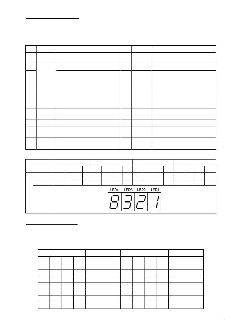
Displaying running status
To display the running status in hexadecimal format, each state has been assigned to bits 0 to 15 as
listed in Table 3.13. Table 3.14 shows the relationship between each of the status assignments and
the LED monitor display. Table 3.15 gives the conversion table from 4-bit binary to hexadecimal.
Table 3.13 Running Status Bit Assignment
Bit Notation Content Bit Notation Content
15 BUSY
14 Always "0." 6 TL "1" under torque limiting control.
13
12 RL
11 ALM "1" when an alarm has occurred. 3 INT
10 DEC "1" during deceleration. 2 EXT "1" during DC braking.
9 ACC "1" during acceleration. 1 REV
8 IL "1" under current limiting control. 0 FWD
LED No. LED4 LED3 LED2 LED1
Bit 15 14 13 12 11 10 9 8 7 6 5 4 3 2 1 0
Notation BUSY WR RL ALM DEC ACC IL VL TL NUV BRK INT EXT REV FWD
Binary 1 0 0 0 0 0 1 1 0 0 1 0 0 0 0 1
Hexadecimal
on the
Example
LED
monitor
"1" when function code data is
being written.
WR
Always "0." 5 NUV
"1" when communication is
enabled (when ready for run and
frequency commands via
communications link).
Table 3.14 Running Status Display
7 VL "1" under voltage limiting control.
"1" when the DC link bus voltage is
higher than the undervoltage
level.
4 BRK "1" during braking.
"1" when the inverter output is
shut down.
"1" during running in the reverse
direction.
"1" during running in the forward
direction.
Hexadecimal expression
A 4-bit binary number can be expressed in hexadecimal format (1 hexadecimal digit). Table 3.15
shows the correspondence between the two notations. The hexadecimals are shown as they appear
on the LED monitor.
Table 3.15 Binary and Hexadecimal Conversion
Binary Hexadecimal Binary Hexadecimal
0 0 0 0
0 0 0 1
0 0 1 0
0 0 1 1
0 1 0 0
0 1 0 1
0 1 1 0
0 1 1 1
1 0 0 0
1 0 0 1
1 0 1 0
1 0 1 1
1 1 0 0
1 1 0 1
1 1 1 0
1 1 1 1
3-18
C
D
E
F
G
H
Page 69

3.4.5 Checking I/O signal status -- Menu #4 "I/O Checking" --
Using Menu #4 "I/O Checking" displays the I/O status of external signals including digital and analog
I/O signals without using a measuring instrument. Table 3.16 lists check items available. The menu
transition in Menu #4 "I/O Checking" is shown in Figure 3.5.
Figure 3.5 Menu Transition in Menu #4 "I/O Checking"
3-19
Page 70

Basic key operation
To check the status of the I/O signals, set function code E52 to "2" (Full-menu mode) beforehand.
(1) Turn the inverter ON. It automatically enters Running mode. In that mode, press the
key to
switch to Programming mode. The function selection menu appears.
(2) Use the
(3) Press the
(4) Use the
The corresponding I/O check data appears. For the item
and keys to display "I/O Checking" (
key to proceed to a list of I/O check items (e.g.
KAQ
).
A
).
and keys to display the desired I/O check item, then press the key.
A
or
A
, using the and
keys switches the display method between the segment display (for external signal information
in Table 3.17) and hexadecimal display (for I/O signal status in Table 3.18).
(5) Press the
key to return to a list of I/O check items. Press the key again to return to the
menu.
Table 3.16 I/O Check Items
LED monitor
shows:
A
A
A
A
A
A
A
A
A
A
A
A
I/O signals on the control
circuit terminals
I/O signals on the control
circuit terminals under
communications control
Input voltage on terminal [12] Shows the input voltage on terminal [12] in volts (V).
Input current on terminal [C1] Shows the input current on terminal [C1] in
Output voltage to analog meters
[FM]
Pulse rate of [FM] Shows the output pulse rate on terminal [FM] in pulses
Input voltage on terminal [C1] Shows the input voltage on terminal [C1] (V2 function
Option control circuit terminal
(I/O)
PG pulse rate 1
(A/B phase)
PG pulse rate 1 (Z phase) Shows the pulse rate (p/s) in Z phase when the PG
PG pulse rate 2
(A/B phase)
PG pulse rate 2 (Z phase) Shows the second PG pulse rate (p/s) in Z phase
Item Description
Shows the ON/OFF state of the digital I/O terminals.
Refer to " Displaying control I/O signal terminals
the next page for details.
Shows the ON/OFF state of the digital I/O terminals
that received a command via RS-485 and optional
communications. Refer to " Displaying control I/O
signal terminals" and " Displaying control I/O signal
terminals under communications control" on the
following pages for details.
milliamperes (mA).
Shows the output voltage on terminal [FM] in volts (V).
per second (p/s).
assigned) in volts (V).
Shows the ON/OFF state of the digital I/O terminals on
the digital I/O interface option. Refer to " Displaying
control I/O signal terminals on digital I/O interface
option" on page 3-22 for details.
Shows the PG pulse rate inputted when the PG
interface is installed.
Displayed value = Pulse rate (p/s) y 1000
interface is installed.
Shows the second PG pulse rate inputted when two
PG interfaces are installed.
Displayed value = Pulse rate (p/s) y 1000
when two PG interfaces are installed.
" on
3-20
Page 71
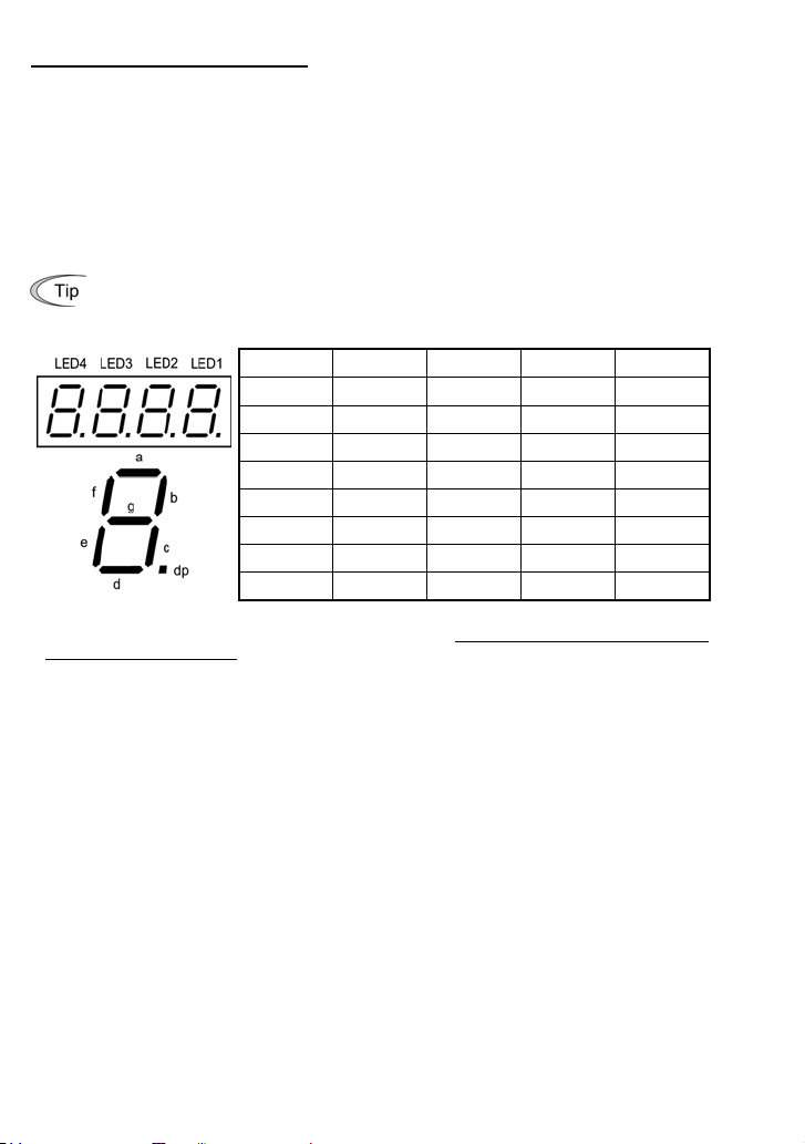
Displaying control I/O signal terminals
The status of control I/O signal terminals may be displayed with ON/OFF of the LED segment or in
hexadecimal display.
Display I/O signal status with ON/OFF of each LED segment
•
As shown in Table 3.17 and the figure below, each of segments "a" to "g" on LED1 lights when the
corresponding digital input terminal circuit ([FWD], [REV], [X1], [X2], [X3], [X4] or [X5]) is closed; it
goes off when it is open. Segment "a" and "b" on LED3 light when the circuit between output terminal
[Y1] or [Y2] and terminal [CMY], and do not light when the circuit is open. Segment "a" on LED4 is for
terminals [30A/B/C]. Segment "a" on LED4 lights when the circuit between terminals [30C] and [30A]
is short-circuited (ON) and does not light when it is open.
If all terminal input signals are OFF (open), segment "g" on all of LED1 to LED4 will light
("– – – –").
* (XF), (XR), and (RST) are assigned for communication. Refer to " Displaying control I/O signal terminals
under communications control
Displaying I/O signal status in hexadecimal format
•
Each I/O terminal is assigned to bit 15 through bit 0 as shown in Table 3.18. An unassigned bit is
interpreted as "0." Allocated bit data is displayed on the LED monitor as four hexadecimal digits (
toH each).
With the FRENIC-Multi, digital input terminals [FWD] and [REV] are assigned to bit 0 and bit 1,
respectively. Terminals [X1] through [X5] are assigned to bits 2 through 6. The bit is set to "1" when
the corresponding input terminal is short-circuited (ON), and is set to "0" when it is open (OFF). For
example, when [FWD] and [X1] are ON (short-circuited) and all the others are OFF (open),
displayed on LED4 to LED1.
Digital output terminal [Y1] and [Y2] are assigned to bits 0 and 1. Each bit is set to "1" when the
terminal is short-circuited with [CMY], and "0" when it is open.
The status of the relay contact output terminal [30A/B/C] is assigned to bit 8. It is set to "1" when the
circuit between output terminals [30A] and [30C] is closed, and "0" when the circuit between [30A]
and [30C] is open.
For example, if [Y1] is ON, [Y2] is OFF, and the circuit between [30A] and [30C] is closed, then
"
" is displayed on the LED4 to LED1.
Table 3.18 presents an example of bit assignment and corresponding hexadecimal display on the
7-segment LED.
Table 3.17 Segment Display for External Signal Information
Segment LED4 LED3 LED2 LED1
a 30A/B/C Y1-CMY — FWD
b — Y2-CMY — REV
c — — — X1
d — — — X2
e — — — X3
f — — (XF)* X4
g — — (XR)* X5
dp — — (RST)* —
—: No corresponding control circuit terminal exists
" on the next page.
is
3-21
Page 72

Table 3.18 Segment Display for I/O Signal Status in Hexadecimal Format
LED No. LED4 LED3 LED2 LED1
Bit 15 14 1312111098 765432 1 0
Input
terminal
Output
terminal
Binary 0 0 000000000001 0 1
Hexadecimal on
the LED
Example
monitor
* (XF), (XR), and (RST) are assigned for communication. Refer to " Displaying control I/O signal
terminals under communications control" below.
(RST)* (XR)* (XF)*
- - - - - - -
- - - - - - X5X4X3X2X1 REV
FWD
30
------ Y2 Y1
A/B/C
– No corresponding control circuit terminal exists.
Displaying control I/O signal terminals under communications control
Under communications control, input commands (function code S06) sent via RS-485 or other
optional communications can be displayed in two ways: "with ON/OFF of each LED segment" and "in
hexadecimal format." The content to be displayed is basically the same as that for the control I/O
signal terminal status display; however, (XF), (XR), and (RST) are added as inputs. Note that under
communications control, the I/O display is in normal logic (using the original signals not inverted).
Refer to the RS-485 Communication User's Manual for details on input commands sent through
RS-485 communications and the instruction manual of communication-related options as well.
Displaying control I/O signal terminals on digital I/O interface option
The LED monitor can also show the signal status of the terminals on the digital I/O interface option,
just like the control circuit terminals.
Table 3.19 lists the assignment between LED segments and I/O signals.
Table 3.19 Segment Display for External Signal Information
Segment LED4 LED3 LED2 LED1
a — O1 I9 I1
b — O2 I10 I2
c — O3 I11 I3
d — O4 I12 I4
e — O5 SEL I5
f — O6 — I6
g — O7 — I7
dp — O8 — I8
LED No. LED4 LED3 LED2 LED1
Bit 15 14 13 12 11 10 9 8 7 6 5 4 3 2 1 0
Input
terminal
Output
terminal
- - -SELI12I11I10I9I8I7I6I5I4I3 I2 I1
- - - - - - - - O8 O7 O6 O5 O4 O3 O2 O1
3-22
Page 73

3.4.6 Reading maintenance information -- Menu #5 "Maintenance Information" --
Menu #5 "Maintenance Information" contains information necessary for performing maintenance on
the inverter. The menu transition in Menu #5 "Maintenance information" is as same as its of in Menu
#3 "Drive Monitoring."
Basic key operation
To view the maintenance information, set function code E52 to "2" (Full-menu mode) beforehand.
(1) Turn the inverter ON. It automatically enters Running mode. In that mode, press the
key to
switch to Programming mode. The function selection menu appears.
(2) Use the
(3) Press the
(4) Use the
and keys to display "Maintenance Information" (
key to proceed to a list of maintenance item codes (e.g.
EJG
).
A
).
and keys to display the desired maintenance item, then press the key.
The data of the corresponding maintenance item appears.
(5) Press the
key to return to a list of maintenance items. Press the key again to return to the
menu.
Table 3.20 Display Items for Maintenance Information
LED
Monitor
shows:
A
A
A
A
A
A
A
Item Description
Cumulative run
time
DC link bus
voltage
Max.
temperature of
heat sink
Max. effective
output current
Capacitance of
the DC link bus
capacitor
Cumulative run
time of
electrolytic
capacitors on the
printed circuit
boards
Cumulative run
time of the
cooling fan
Shows the content of the cumulative power-ON time counter of the
inverter.
Unit: thousands of hours.
(Display range: 0.001 to 9.999, 10.00 to 65.53)
When the total ON-time is less than 10000 hours (display: 0.001 to
9.999), data is shown in units of one hour (0.001). When the total time is
10000 hours or more (display: 10.00 to 65.53), it is shown in units of 10
hours (0.01). When the total time exceeds 65535 hours, the counter will
be reset to 0 and the count will start again.
Shows the DC link bus voltage of the inverter main circuit.
Unit: V (volts)
Shows the maximum temperature of the heat sink for every hour.
Unit: qC (Temperatures below 20qC are displayed as 20qC.)
Shows the maximum current in RMS for every hour.
Unit: A (amperes)
Shows the current capacitance of the DC link bus capacitor (reservoir
capacitor) in %, based on the capacitance when shipping as 100%.
Refer to Chapter 7 "MAINTENANCE AND INSPECTION" for details.
Unit: %
Shows the content of the cumulative run time counter of the electrolytic
capacitors mounted on the printed circuit boards.
Unit: thousands of hours. (Display range: 0.001 to 99.99)
Shown in units of 10 hours.
When the total time exceeds 99990 hours, the count stops and the
display remains at 99.99.
Shows the content of the cumulative run time counter of the cooling fan.
This counter does not work when the cooling fan ON/OFF control
(function code H06) is enabled and the fan is stopped.
Unit: thousands of hours. (Display range: 0.001 to 99.99)
Shown in units of 10 hours.
When the total time exceeds 99990 hours, the count stops and the
display remains at 99.99.
3-23
Page 74

LED
Monitor
shows:
A
A
A
A
A
A
A
A
A
A
A
A
Table 3.20 Display Items for Maintenance Information (Continued)
Item Description
Number of
startups
Input watt-hour Shows the input watt-hour of the inverter.
Input watt-hour
data
Number of
RS-485
errors
(standard)
Content of
RS-485
communication
s error
(standard)
Number of
option errors
Inverter's ROM
version
Keypad's ROM
version
Number of
RS-485 errors
(option)
Content of
RS-485
communication
s error (option)
Option's ROM
version
Cumulative
motor run time
Shows the content of the cumulative counter of times the inverter is
started up (i.e., the number of run commands issued).
1.000 indicates 1000 times. When any number from 0.001 to 9.999 is
displayed, the counter increases by 0.001 per startup, and when any
number from 10.00 to 65.53 is counted, the counter increases by 0.01
every 10 startups. When the counted number exceeds 65535, the
counter will be reset to 0 and the count will start again.
Unit: 100 kWh (Display range: 0.001 to 9999)
Depending on the value of integrated input watt-hour, the decimal point
on the LED monitor shifts to show it within the LED monitor’s resolution
(e.g. the resolution varies between 0.001, 0.01, 0.1 or 1). To reset the
integrated input watt-hour and its data, set function code E51 to "0.000."
When the input watt-hour exceeds 1000000 kWh, it returns to "0."
Shows the value expressed by "input watt-hour (kWh) × E51 (whose
data range is 0.000 to 9999)."
Unit: None.
(Display range: 0.001 to 9999. The data cannot exceed 9999. (It will be
fixed at 9999 once the calculated value exceeds 9999.))
Depending on the value of integrated input watt-hour data, the decimal
point on the LED monitor shifts to show it within the LED monitors’
resolution.
To reset the integrated input watt-hour data, set function code E51 to
"0.000."
Shows the total number of errors that have occurred in standard RS-485
communication (via the RJ-45 connector as standard) since the power
is turned ON.
Once the number of errors exceeds 9999, the count returns to 0.
Shows the most recent error that has occurred in standard RS-485
communication in decimal format.
For error contents, refer to the RS-485 Communication User’s Manual.
Shows the total number of optional communications card errors since
the power is turned ON.
Once the number of errors exceeds 9999, the count returns to 0.
Shows the inverter's ROM version as a 4-digit code.
Shows the keypad's ROM version as a 4-digit code.
Shows the total number of errors that have occurred in optional RS-485
communication since the power is turned ON.
Once the number of errors exceeds 9999, the count returns to 0.
Shows the most recent error that has occurred in optional RS-485
communication in decimal format.
For error contents, refer to the RS-485 Communication User’s Manual.
Shows the option's ROM version as a 4-digit code.
Shows the content of the cumulative power-ON time counter of the
motor.
The display method is the same as for "Cumulative run time" (
above.
3-24
A
)
Page 75

3.4.7 Reading alarm information -- Menu #6 "Alarm Information" --
Menu #6 "Alarm Information" shows the causes of the past 4 alarms in alarm code. Further, it is also
possible to display alarm information that indicates the status of the inverter when the alarm
occurred. Figure 3.6 shows the menu transition in Menu #6 "Alarm Information" and Table 3.21 lists
the details of the alarm information.
Figure 3.6 "Alarm Information" Menu Transition
3-25
Page 76

Basic key operation
To view the alarm information, set function code E52 to "2" (Full-menu mode) beforehand.
(1) Turn the inverter ON. It automatically enters Running mode. In that mode, press the
key to
switch to Programming mode. The function selection menu appears.
(2) Use the
(3) Press the
and keys to display "Alarm Information" (
key to proceed to a list of alarm codes (e.g.
CN
N
).
).
In the list of alarm codes, the alarm information for the last 4 alarms is saved as an alarm history.
(4) Each time the
recent one as
(5) While the alarm code is displayed, press the
number (e.g.
approximately 1 second. You can also have the item number (e.g.
current) for any other item displayed using the
(6) Press the
LED monitor
shows:
(item No.)
A
or key is pressed, the last 4 alarms are displayed in order from the most
, , and .
key to have the corresponding alarm item
A
) and data (e.g. Output frequency) displayed alternately in intervals of
A
) and data (e.g. Output
and keys.
key to return to a list of alarm codes. Press the key again to return to the menu.
Table 3.21 Alarm Information Displayed
Item displayed Description
Output frequency Output frequency
A
A
A
A
A
A
A
A
A
Output current Output current
Output voltage Output voltage
Calculated
torque
Reference
frequency
Rotational
direction
Running status
Cumulative run
time
No. of startups
DC link bus
voltage
Calculated motor output torque
Frequency specified by frequency command
This shows the rotational direction being output.
H
: forward, T: reverse, : stop
This shows the running status in hexadecimal. Refer to
" Displaying running status
Shows the content of the cumulative power-ON time counter of the
inverter.
Unit: thousands of hours.
(Display range: 0.001 to 9.999, 10.00 to 65.53)
When the total ON-time is less than 10000 hours (display: 0.001 to
9.999), data is shown in units of one hour (0.001). When the total
time is 10000 hours or more (display: 10.00 to 65.53), it is shown in
units of 10 hours (0.01). When the total time exceeds 65535 hours,
the counter will be reset to 0 and the count will start again.
Shows the content of the cumulative counter of times the inverter is
started up (i.e., the number of run commands issued).
1.000 indicates 1000 times. When any number from 0.001 to 9.999
is displayed, the counter increases by 0.001 per startup, and when
any number from 10.00 to 65.53 is counted, the counter increases
by 0.01 every 10 startups. When the counted number exceeds
65535, the counter will be reset to 0 and the count will start again.
Shows the DC link bus voltage of the inverter main circuit.
Unit: V (volts)
" in Section 3.4.4.
3-26
Page 77

Table 3.21 Alarm Information Displayed (Continued)
LED monitor
shows:
(item No.)
A
A
A
A
A
A
A
A
A
A
A
When the same alarm occurs repeatedly in succession, the alarm information for the first
occurrences will be preserved and the information for other occurrences in-between will be
discarded. The number of consecutive occurrences will be preserved as the first alarm
information.
Item displayed Description
Max. temperature of heat sink
Terminal I/O signal status
(displayed with the ON/OFF of
LED segments)
Terminal input signal status
(in hexadecimal format)
Terminal output
signal status
(in hexadecimal format)
No. of consecutive
occurrences
Multiple alarm 1
Multiple alarm 2
Terminal I/O signal status
under communications control
(displayed with the ON/OFF of
LED segments)
Terminal input signal status
under communications control
(in hexadecimal format)
Terminal output signal status
under communications control
(in hexadecimal format)
Error sub code
Shows the temperature of the heat sink.
Unit: ºC
Shows the ON/OFF status of the digital I/O terminals.
Refer to " Displaying control I/O signal terminals
Section 3.4.5 "Checking I/O signal status" for details.
This is the number of times the same alarm occurs
consecutively.
Simultaneously occurring alarm codes (1)
" is displayed if no alarms have occurred.)
("
Simultaneously occurring alarm codes (2)
" is displayed if no alarms have occurred.)
("
Shows the ON/OFF status of the digital I/O terminals
under RS-485 communications control. Refer to
" Displaying control I/O signal terminals under
communications control" in Section 3.4.5 "Checking
I/O signal status" for details.
Secondary error code for the alarm.
" in
3.5 Alarm Mode
If an abnormal condition arises, the protective function is invoked and issues an alarm, then the
inverter automatically enters Alarm mode. At the same time, an alarm code appears on the LED
monitor.
Releasing the alarm and switching to Running mode
Remove the cause of the alarm and press the
mode. The alarm can be removed using the
Displaying the alarm history
It is possible to display the most recent 3 alarm codes in addition to the one currently displayed.
Previous alarm codes can be displayed by pressing the
displayed.
key to release the alarm and return to Running
key only when the latest alarm code is displayed.
/ key while the current alarm code is
3-27
Page 78

Displaying the status of inverter at the time of alarm
When the alarm code is displayed, you may check various running status information (output
frequency and output current, etc.) by pressing the
key. The item number and data for each
running information will be displayed alternately.
Further, you can view various pieces of information on the running status of the inverter using the
/ key. The information displayed is the same as for Menu #6 "Alarm Information" in Programming
mode. Refer to Table 3.21 in Section 3.4.7, "Reading alarm information."
Pressing the
key while the running status information is displayed returns the display to the alarm
codes.
When the running status information is displayed after removal of the alarm cause, pressing
key twice returns to the alarm code display and releases the inverter from the alarm
the
state. This means that the motor starts running if a run command has been received by this
time.
Switching to Programming mode
You can also switch to Programming mode by pressing
+ keys simultaneously with the alarm
displayed, and modify the function code data.
Figure 3.7 summarizes the possible transitions between different menu items.
Figure 3.7 Menu Transition in Alarm Mode
3-28
Page 79
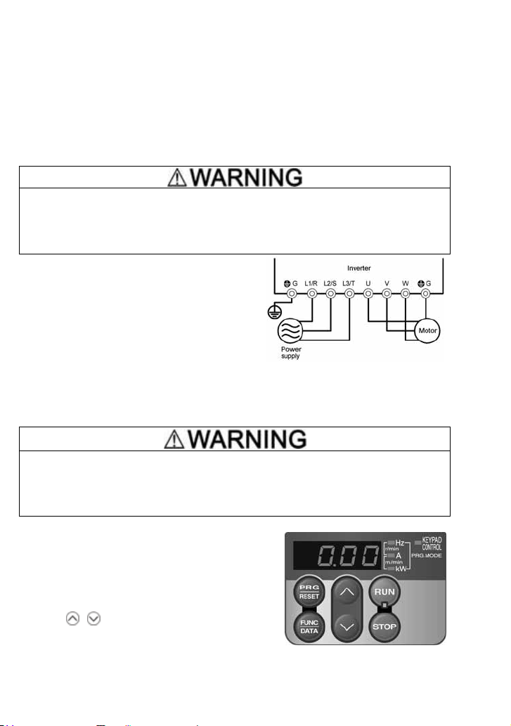
Chapter 4 RUNNING THE MOTOR
r
4.1 Running the Motor for a Test
4.1.1 Inspection and preparation prior to powering on
Check the following prior to powering on.
(1) Check if connection is correct.
Especially check if the power wires are connected to the inverter input terminals L1/R, L2/S and
L3/T or L1/L and L2/N, and output terminals U, V and W respectively and that the grounding
wires are connected to the ground electrodes correctly. Refer to Figure 4.1.
• Do not connect power supply wires to the inverter output terminals U, V, and W. Otherwise, the
inverter may be broken if you turn the power ON.
• Be sure to connect the grounding wires of the inverter and the motor to the ground electrodes.
Otherwise, electric shock may occur.
(2) Check for short circuits between terminals and
exposed live parts and ground faults.
(3) Check for loose terminals, connectors and screws.
(4) Check if the motor is separated from mechanical
equipment.
(5) Turn the switches OFF so that the inverter does not
start or operate erroneously at power-on.
(6) Check if safety measures are taken against
runaway of the system, e.g., a defense to protect
people from unexpectedly approaching your powe
system.
4.1.2 Turning ON power and checking
(E.g. Wire connection for three-phase
power supply)
Figure 4.1 Connection of Main Circuit
Terminals
• Be sure to install the terminal cover if any before turning the power ON.
Do not remove any cover while powering on.
• Do not operate switches with wet hands.
Otherwise electric shock could occur.
Turn the power ON and check the following points. This is a
case when no function code data is changed from the
factory setting.
(1) Check if the LED monitor displays
(means that
the frequency command is 0 Hz) that is blinking. (See
Figure 4.2.)
If the LED monitor displays numbers except
/
press
keys to set
as the frequency
,
command.
(2) Check if a built-in cooling fan rotates.
(For the inverter of 1 HP or below, no cooling fan is
Figure 4.2 Display of the LED Monitor
mounted.)
4-1
after Power-on
Page 80

4.1.3 Preparation before running the motor for a test--Setting function code data
Before running the motor, set function code data specified in Table 4.1 to the motor ratings and your
system design values. For the motor, check the rated values printed on the nameplate of the motor.
For your system design values, ask system designers about them.
For details about how to change function code data, refer to Chapter 3, Section 3.4.1 "Setting
up function codes quickly." Refer to the function code H03 in Chapter 5 "FUNCTION CODES"
for the factory default setting of motor parameters. If any of them is different from the default
setting, change the function code data.
Table 4.1 Settings of Function Code Data before Driving the Motor for a Test
Function code Name Function code data Factory setting
H(C
H(C)
R(C)
R(C)
R(C)
H(C)
H
H
Base frequency 60.0 (Hz)
)
Rated voltage
at base frequency
Motor parameter
(Rated capacity)
Motor parameter
(Rated current)
Motor selection
Maximum frequency 60.0 (Hz)
Acceleration time 1* 6.0 (s)
Deceleration time 1*
Motor ratings
(printed on the nameplate
of the motor)
System design values
*
For a test-driving of the
motor, increase values
so that they are longer
than your system design
values. If the set time is
short, the inverter may
not start running the
motor.
Three-phase 230 V class series: 230 (V)
Three-phase 460 V class series: 460 (V)
Applicable motor rated capacity
Rated current of applicable motor
0: Motor characteristics 0
6.0 (s)
(Fuji standard 8-series motors)
In any of the following cases, the default settings may not produce the best results for
auto torque boost, torque calculation monitoring, auto energy saving, torque limiter,
automatic deceleration, auto search for idling motor speed, slip compensation, torque
vector, droop control, or overload stop, since the standard settings of motor parameters
for Fuji motors are not applicable. Tune the motor parameters according to the
procedure set forth below.
• The motor to be driven is not a Fuji product or is a non-standard product.
• The cabling between the motor and the inverter is long.
• A reactor is inserted between the motor and the inverter.
A codes are used to specify the data for motor 2. Use them if necessary.
㧨Tuning procedure㧪
1) Preparation
Referring to the rating plate on the motor, set the following function codes to their nominal
ratings:
• F04 and A02: Base frequency
• F05 and A03: Rated voltage at base frequency
• P02 and A16: Rated capacity
• P03 and A17: Rated current
4-2
Page 81

2) Selection of tuning process
Check the situation of the machine system and choose between "Tuning while the motor is
stopped (P04 or A18 = 1)" and "Tuning while the motor is running (P04 or A18 = 2)." In the
case of "Tuning while the motor is running (P04 or A18 = 2)," also adjust the acceleration
and deceleration times (F07 and F08) and set the rotation direction properly so that it
matches the actual rotation direction of the machine system.
Data for
P04, A18
Motor parameters
subjected to tuning:
Primary resistance
(%R1)
1
Leakage reactance
(%X)
Primary resistance
(%R1)
Leakage reactance
(%X)
2
No-load current
Rated slip frequency
Tuning type
Tuning the %R1 and %X,
with the motor being
stopped.
Tuning the %R1, %X and
rated slip frequency, with
the motor being stopped.
Tuning the no-load current,
with the motor running
50% of the base frequency.
Lastly, tuning the rated slip
frequency, with the motor
being stopped.
at
Selection condition
of tuning type
The motor cannot be rotated,
or more than 50% of the rated
load would be applied on the
motor if rotated.
Even if the motor is rotated, it
is safe and the load applied
on the motor would be no
more than 50% of the rating.
(If you do the tuning with no
load, you will get the highest
precision.)
Upon completion of the tuning, each motor parameter will be automatically saved into the
applicable function code.
3) Preparation of machine system
Perform appropriate preparations on the motor and its load, such as disengaging the
coupling and deactivating the safety device.
Switch to the motor 1 or motor 2, which the tuning is to be performed on.
Tuning results by P04 will be applied to P codes for the motor 1, and the tuning results by
A18 will be applied to A codes for the motor 2.
Assigning the command "Switch to motor 2 SWM2" to any of the terminal [Y1],
[Y2], or [30A/B/C] will automatically switch the output status of SWM2 depending
on the motor selected for the tuning.
4) Perform tuning
Set function code P04 or A18 to "1" or "2" and press the key. (The blinking of or
on the LED monitor will slow down.)
Enter a run command for the rotation direction selected. The factory default is " key
on the keypad for forward rotation." To switch to reverse rotation, change the data of
function code F02.
The display of or stays lit, and tuning takes place while the motor being stopped.
(Maximum tuning time: Approx. 40 s.)
If P04 or A18 = 2, the motor is accelerated to approximately 50% of the base frequency
and then tuning takes place. Upon completion of measurements, the motor will
decelerate to a stop.
Tuning will continue after the motor is stopped.
(Maximum tuning time: Approx. 10 s.)
If the terminal signal FWD or REV is selected as the run command (F02 = 1),
GPF
will appear upon completion of the measurements.
The run command is turned OFF. (The run command given through the keypad or the
communications link is automatically turned OFF).
R
or
C
The tuning completes and the next function code
4-3
appears on the keypad.
Page 82

Errors during tuning
Improper tuning would negatively affect the operation performance and, in the worst case,
could even cause hunting or deteriorate precision. Therefore, if the inverter finds any
abnormality in the results of the tuning or any error in the process of the tuning, it will
display
GT
and discard the tuning data.
Listed below are the abnormal or error conditions that can be recognized during tuning.
Possible tuning
error causes
Error in tuning
results
Output current
error
Sequence error
Error due to
limitation
Other errors
- An interphase voltage unbalance has been detected.
- Tuning has resulted in an abnormally high or low value of a parameter.
An abnormally high current has flown during tuning.
During tuning, a run command has been turned OFF, or STOP (Force to
stop), BX (Coast to a stop), DWP (Protect from dew condensation), or other
similar terminal command has been received.
- During tuning, any of the operation limiters has been activated.
- The maximum frequency or the frequency limiter (high) has limited tuning
operation.
An undervoltage or any other alarm has occurred.
Details
If any of these conditions has occurred, either eliminate the abnormal or error factor(s) and
perform tuning again, or consult your Fuji Electric representative.
If a filter other than Fuji optional output filter (OFL--4A) is connected to
the inverter's output (secondary) circuit, the result of tuning can be
unpredictable. When you replace an inverter, make a note of the old inverter’s
settings for the primary resistance %R1, leakage reactance %X, no-load
current, and rated slip frequency, and set those values to the new inverter’s
function codes.
4.1.4 Test run
If the user specifies the function codes wrongly or without completely understanding this
Instruction Manual and the FRENIC-Multi User's Manual, the motor may rotate with a torque or at
a speed not permitted for the machine.
Accident or injury may result.
Follow the descriptions given in Section 4.1.1, "Inspection and preparation prior to powering on" to
Section 4.1.3, "Preparation before running the motor for a test," then begin test-driving of the motor.
If any abnormality is found in the inverter or motor, immediately stop operation and determine the
cause referring to Chapter 6, "TROUBLESHOOTING."
4-4
Page 83

------------------------------------------------ Test Run Procedure -------------------------------------------------
(1) Turn the power ON and check that the reference frequency
monitor.
(2) Set a low reference frequency such as 5 Hz, using
blinking on the LED monitor.)
(3) Press the
frequency is displayed on the LED monitor.)
(4) To stop the motor, press the
< Check points during a test run >
• Check that the motor is running in the forward direction.
• Check for smooth rotation without motor humming or excessive vibration.
• Check for smooth acceleration and deceleration.
When no abnormality is found, press the
reference frequency using
If any problem is found, modify the function code data again as described below.
----------------------------------------------------------------------------------------------------------------------------------
key to start running the motor in the forward direction. (Check that the reference
key.
/
keys. Check the above points again.
key again to start driving the motor, then increase the
Hz is blinking on the LED
/ keys. (Check that the frequency is
4.2 Operation
After confirming that the inverter normally drives the motor in a test run, make mechanical
connections (connections to the machine system) and electrical connections (wiring and cabling),
and configure the necessary function codes properly before starting a production run.
Depending on the production run conditions, further adjustments can be required, such
as adjustments of torque boost (F09/A05), acceleration time (F07/E10), and deceleration
time (F08/E11).
4.2.1 Jogging Operation
This section provides the procedure for jogging the motor.
Making the inverter ready to jog with the steps below. The LED monitor should display
• Enter Running mode (see page 3-3).
• Press the
approximately one second and then returns to
Jogging the motor.
Hold down the
release the key.
Exiting the ready-to-jog state and returning to the normal operation state
Press the
+ keys simultaneously. The LED monitor displays the jogging frequency for
• Function codes C20 and H54 specify the jogging frequency and acceleration/
deceleration time, respectively. Use these function codes exclusively for the
jogging operation with your needs.
• Using the input terminal command "Ready for jogging" JOG switches between the
normal operation state and ready-to-jog state.
• Switching between the normal operation state and read-to-jog state with the
keys is possible only when the inverter is stopped.
key during which the motor continues jogging. To decelerate to stop the motor,
+ keys simultaneously.
LQI
again.
LQI
.
+
4-5
Page 84

Chapter 5 FUNCTION CODES
5.1 Function Code Tables
The following tables list the function codes available for the FRENIC-Multi series of inverters.
F codes: Fundamental Functions
Code
F00 0 :
F01 0: UP/DOWN keys on keypad
F02 0 : 㧙㧙 NY 2
F03 25.0 to 400.0 0.1 Hz N Y 60.0
F04 25.0 to 400.0 0.1 Hz N Y 60.0 5-21
F05 0: 1 V N Y2
F06 80 to 240: 1 V N Y2 230
F07 0.00 to 3600 0.01 s Y Y 6.00
F08 0.00 to 3600 0.01 s Y Y 6.00
F09 0.1 % Y Y *4 5-23
F10 1 :
F11 0.01 A Y Y1Y2 *4
F12 0.5 to 75.0 0.1 min Y Y 5.0
F14 0: Disable restart (Trip immediat ely) 㧙㧙 YY 05-28
F15 Frequency Limiter (High) 0.0 to 400.0 0.1 Hz Y Y 70.0 5-31
F16 (Low) 0.0 to 400.0 0.1 Hz Y Y 0.0
F18 -100.00 to 100.00 *1 0.01 % Y* Y 0.00 5-32
F20
F21 (Braking level) 0 to 100 1% Y Y 0
F22 (Braking time) 0.01 s Y Y 0.00
F23 0.1 to 60.0 0.1 Hz Y Y 0.5 5-34
F24 (Holding time) 0.00 to 10.00 0.01 s Y Y 0.00
F25 0.1 to 60.0 0.1 Hz Y Y 0.2
The shaded function codes ( ) are applicable to the quick setup.
1
*
When you make settings from the keypad, the incremental unit is restricted by the number of digits that the LED monitor can
display.
(Example) If the setting range is from -200.00 to 200.00, the incremental unit is:
"1" for -200 to -100, "0.1" for -99.9 to -10.0 and for 100.0 to 200.0, and "0.01" for -9.99 to -0.01 and for 0.00 to 99.99.
4
*
Default settings for these function codes vary depending on the inverter capacity. See Table 5.1 "Factory Defaults According
to Inverter Capacity" on pages 5-15 and 5-16.
Name
Data Protection
Frequency Command 1
Operation Meth od
Maximum Frequency 1
Base Frequency 1
Rated Voltage at Base Frequency 1
Maximum Output Voltage 1
Acceleration Time 1
Deceleration Time 1
Torque Boost 1
Electronic Therm al Overload
Protection for Motor 1 For an i nverter-driven motor, non-vent ilated motor, or motor with
(Select motor ch aracteristics)
(Overload detection level)
(Thermal time constant)
Re
start Mode after Momentary Power
Failure
Biasޓޓ (Frequency command 1)
DC Braking 1
Starting Frequency 1
Stop Frequency
(Mode selection) Enable restart (Rest art at the frequency at which the power failure
(Braking starting frequency)
Disable both data protection and digital reference protection
Enable data protection and disable digital reference protection
1:
Disable data protection and enable digital reference protection
2:
Enable both data protection and digital reference protection
3:
1: Voltage input to terminal [12] (-10 to +10 VDC)
2:
Current input to terminal [C1] (C1 function) (4 to 20 mA DC)
3:
Sum of voltage and current inputs to terminals [12] and [C1]
(C1 function)
5:
Voltage input to terminal [C1] (V2 function) (0 to 10 VDC)
7: Terminal command UP/
11: Digital I/O interface option
12: PG interface card (option)
RUN/STOP keys on keypad (Motor rotational direction specified b y
terminal command
1: Terminal command
2: RUN/STOP keys on keypad (forward)
3: RUN/STOP keys on keypad (reverse)
80 to 240: 230
160 to 500: 460
160 to 500: 460
Note: Entering 0.00 cancels the acceleration time, requiring external
soft-start.
Note: Entering 0.00 cancels the deceleration time, requiring external
soft-start.
0.0 to 20.0
(percentage with respect to "F05: Rated Voltage at Base Frequency 1")
Note: This setting takes effect when F37 = 0, 1, 3, or 4.
For a general-purpose motor with shaft-driven cooling fan
2:
separately powered cooling fan
0.00: Disable
0.01 to 100.00
1 to 135% of the rated current (allowable continuous drive current) of the
motor
1: Disable restart (Trip after a recovery from power failure)
4:
occurred, for gen eral loads)
Enable restart (R estart at the starting frequency, for low-inertia load)
5:
0.0 to 60.0 0.1 Hz Y Y 0.0 5-33
0.00 : Disable
0.01 to 30.00
Data setting range
control
DOWN
)
FWD/REV
or
FWD
REV
Output a voltage in proportion to input voltage
Output an AVR-controlled voltage (for 230 V class series)
Output an AVR-controlled voltage (for 460 V class series)
Output an AVR-controlled voltage (for 230 V class series)
Output an AVR-controlled voltage (for 460 V class series)
Change
Incre-
Unit
when
ment
running
㧙㧙
YY 0
㧙㧙
NY 0
㧙㧙
YY 15-25
Data
copying
Default
setting
Refer to
page:
5-18
5-20
5-22
5-1
Page 85

(F codes continued)
p
)(
)
(
)
(SV)
)
g
Change
Code
F26 0.75 to 15 1 kHz Y Y 2 5-34
F27 (Tone) 0: Level 0 (Inactive)
F29 Analog Output [FM] 0: Output in voltage (0 to 10 VDC) (
F30 (Voltage adjustment) 0 to 300 (
F31
F33 (Pulse rate) 25 to 6000 (
F37 0: Variable torque load
F39 Stop Frequency 0.00 to 10.00 0.01 s Y Y 0.00 5-34
F40 1% Y Y 999 5-36
F41 1% Y Y 999
F42 Control Mode Selection 1 0:
F43 Current Limiter 0: Disable (No current limiter works.)
F44 (Level) 1 % Y Y 180 (Note)
F50 1 to 900 1kWs Y Y 999
F51 (Allowable average loss) 0.001 kW Y Y 0.000
Name
Motor Soundޓ (Carrier frequency)
(Mode selection) 2:
Function
Load Selection/Auto Torque Boost/
Auto Energy Saving Operation 1
Torque Limiter 1
(Limiting level for driving)
Electronic Thermal Overload Protection
for Brakin
(Holding Time)
(Limiting level for braking)
(Mode selection) 1:
Resistor
(Discharging capability) 0: Reserved
1: Level 1
2: Level 2
3: Level 3
Out
ut in pulse (0 to 6000 p/s
FMA
Select a function to be monitored from the followings.
0: Output frequency 1 (before slip compensation)
1: Output frequency 2 (after slip compensation)
2: Output current
3: Output voltage
4: Output torque
5: Load f actor
6: Input power
7: PID feedback amount (PV)
8: PG f eedback value
9: DC link bus voltage
10: Universal AO
13: Motor output
14: Calibration
15: PID command
16: PID output (MV)
1: Constant torque load
2: Auto-torque boost
3:
Auto-energy saving operation (Variable torque load during ACC/DEC)
4:
Auto-energy saving operation (Constant torque load during ACC/DEC)
Auto-energy saving operation (Auto-torque boost during ACC/DEC)
5:
20 to 200
999: Disable
20 to 200
999: Disable
V/f control with slip compensation inactive
1: Dynamic torque vector control
V/f control with slip compensation active
2:
V/f control with optional PG interface
3:
Dynamic torque vector control with optional PG interface
4:
Enable at constant speed (Disable during ACC/DEC)
2: Enable during ACC/constant speed operation
20 to 200 (The data is interpreted as the rated output current of the inverter
for 100%.
999: Disable
0.001 to 50.000
0.000: Reserved
Data setting range
)
FMA
)1%Y*Y100
, Pulse rate at 100% output) 1 p/s Y* Y 1440
FMP
FMP
Incre-
ment
㧙㧙
㧙㧙
㧙㧙
㧙㧙
㧙㧙
㧙㧙
Data
Unit
when
copying
running
YY 0
YY 05-35
YY 0
NY 15-23
NY 05-37
Y Y 2 (Note) 5-38
The shaded function codes ( ) are applicable to the quick setup.
(Note) Default settings for inverters with inverter's ROM version 0799 or earlier: F43 = 0 and F44 = 200 (For the inverter's ROM
version checking procedure, refer to Chapter 3, Section 3.4.6 "Reading maintenance information".)
Default
setting
Refer
page:
to
5-2
Page 86

E codes: Extension Terminal Functions
(
y
(
8
)
(
)
(
(BX)
(
(
)
I
R
N
(
(
)
(
A
o
Code
E01 Terminal [X1] Function
E02 Terminal [X2] Function 0 (1000): Select multi-frequency (
E03 Terminal [X3] Function 1 (1001): Select multi-frequency (
E04 Terminal [X4] Function 2 (1002): Select multi-frequency (
E05 Terminal [X5] Function 3
E10 Acceleration Time 2 0.01 s Y Y 10.0 5-22
E11 Deceleration Time 2 0.01 s Y Y 10.0
E16 1%Y Y 999
E17 (Limiting level for braking) 1% Y Y 999
5
*
These are available on inverters with inverter's ROM version 0700 or later. (For the version checking procedure, refer to
Chapter 3, Section 3.4.6 "Reading maintenance information."
Name
Torque Limiter 2
(Limiting level for driving)
Selecting function code data assigns the corresponding function to
terminals [X1] to [X5] as listed below.
1003): Select multi-frequenc
4 (1004): Select ACC/DEC time
6 (1006): Enable 3-wire operation (
1007): Coast to a stop
7
8 (1008): Reset alarm (
9 (1009): Enable external alarm trip (
10 (1010): Ready for jogging (
11 (1011): (
12 (1012): Select motor 2/motor 1 (
13 : Enable DC braking (
14 (1014): Select torque limiter level (
17 (1017): ( UP )
1018):
18
19 (1019): (
20 (1020): Cancel PID control (
21 (1021): (
24 (1024): ( LE )
25 (1025): Universal DI (
26 (1026): (
27 (1027): (
30 (1030): Force to stop (
33 (1033): (
34 (1034): Hold PID integral component (
42 (1042): *5
43 (1043): (
44 (1044): (
45 (1045): (
1046):
46
Setting the value of 1000s in parentheses ( ) shown above assigns a
negative logic input to a terminal.
Note: In the case of
logic, and "9" and "30" are for negative logic, respectively.
0.00 to 3600
Note: Entering 0.00 cancels the acceleration time, requiring external softstart and -stop.
0.00 to 3600
Note: Entering 0.00 cancels the acceleration time, requiring external softstart and -stop.
20 to 200
999 : Disable
20 to 200
999 : Disable
Data setting range
Select frequency command 2/1
UP (Increase output frequency)
DOWN
Decrease output
Enable data change with keypad
Switch normal/inverse operation
Enable communications link via
RS-485 or field bus
Enable auto search for idling
motor speed at starting
Switch to speed feedback
Reset PID integral and
differential components
ctivate the limit switch at start p
Start/reset
Switch to the serial pulse
receiving
Enter the return mode
Enable overload stop
and
, data (1009) and (1030) are for normal
THR
STOP
SS1
SS2
SS4
SS
RT1
HLD
RST
THR
JOG
Hz2/Hz1
M2/M1
DCBRK
TL2/TL1
DOWN
WE-KP
Hz/PID
IVS
U-D
STM
) *5
PG/Hz
STOP
PID-RST
PID-HLD
) *5
S/
) *5
SPRM
) *5
RT
*5
OLS
)
Incre-
ment
㧙㧙
㧙㧙
)
㧙㧙
)
㧙㧙
)
㧙㧙
)
)
)
)
)
)
)
)
)
)
)
)
)
)
)
)
Change
Data
Unit
when
running
Default
copying
NY 05-40
NY 1
NY 2
NY 7
NY 8
setting
Refer
page:
5-36
to
5-3
Page 87

(E codes continued)
(
g
(
)
(
(
)
(
(
)
D
(
(
)
R
(
)
(
)
(Hy
d
(
)
q
)
Code
E20 Terminal [Y1] Function
E21 Terminal [Y2] Function 0 (1000): Inverter running (
E27 Terminal [30A/B/C] Function 1 (1001): Frequency arrival signal (
E29 Frequency Arrival Delay Time 0.01 to 10.00 0.01 s Y Y 0.10 5-52
E30 0.0 to 10.0 0.1 Hz Y Y 2.5
E31 0.0 to 400.0 0.1 Hz Y Y 60.0 -
E32
E34 5-52
E35 (Timer) 0.01 to 600.00 *1 0.01 s Y Y 10.00
E37 0.01 A Y Y1
E38 (Timer) 0.01 to 600.00 *1 0.01 s Y Y 10.00
E39 0.000 to 9.999 0.001㧙Y Y 0.000 5-53
1
*
When you make settings from the keypad, the incremental unit is restricted by the number of digits that the LED monitor can
display.
(Example) If the setting range is from -200.00 to 200.00, the incremental unit is:
"1" for -200 to -100, "0.1" for -99.9 to -10.0 and for 100.0 to 200.0, and "0.01" for -9.99 to -0.01 and for 0.00 to 99.99.
4
*
Default settings for these function codes vary depending on the inverter capacity. See Table 5.1 "Factory Defaults According
to Inverter Capacity" on pages 5-15 and 5-16.
5
*
These are available on inverters with inverter's ROM version 0700 or later. (For the version checking procedure, refer to
Chapter 3, Section 3.4.6 "Reading maintenance information."
6
*
These are available on inverters with inverter's ROM version 0800 or later. (For the version checking procedure, refer to
Chapter 3, Section 3.4.6 "Reading maintenance information."
Name Data setting range
Selecting function code data assigns the corresponding function to
terminals [Y1], [Y2], and [30A/B/C] as listed below.
2 (1002): Frequency detected (
3 (1003): ( LU )
4 (1004): Torque polarity detected (
1005): Inverter output limitin
5
6 (1006): (
7 (1007): ( OL )
1010): Inverter ready to run
10
21 (1021): Frequency arrival signal 2 (
22 (1022): (
26 (1026): Auto-resetting (
27 (1027): (
28 (1028): ( OH )
30 (1030): S ervice lifetime alarm (
1033): Ref erence loss detected
33
35 (1035): Inverter output on (
36 (1036): Overload prevention control (
37 (1037): Current detected (
38 (1038): Current detected 2 (
1042): P ID alarm
42
49 (1049): Switched to motor 2 (
56 (1056): (
57 (1057): Brake signal (
59 (1059): (
76 (1076): (
80 (1080): ( OT ) *5
81 (1081): ( TO ) *5
82 (1082): (
83 (1083): (
1099):Alarm output (for any alarm
99
Setting the value of 1000s in parentheses ( ) shown above assigns a
negative logic input to a terminal.
Frequency Arrival
(Hysteresis width)
Fre
uency Detection (FDT
Detection level
Overload Early Warning/Current
Detection
Current Detection 2ޓ (Level)
Coefficient for Constant Feeding Rate
Time
steresis width) 0.0 to 400.0 0.1 Hz Y Y 1.0
(Level) 0.01 A Y Y1
0.00 : Disable
Current value of 1 to 200% of the inverter rated current
0.00 : Disable
Current value of 1 to 200% of the inverter rated current
Undervoltage detected
(Inverter stopped)
Auto-restarting after momentary
power failure
Motor overload early warning
Inverter output limiting with delay
Universal DO
Heat sink overheat early warning
Motor overheat detected by
thermistor (PTC)
Terminal [C1] wire break
PG error detected
Stop position override alarm
Timer output
Positioning completed
Current position count overflowe
)
RUN
)
FAR
)
FDT
)
B/D
IOL
)
IPF
RDY
)
FAR2
)
IOL2
)
TRY
) *6
U-DO
)
LIFE
REF OFF
)
RUN2
)
OLP
)
I
)
ID2
PID-ALM
)
SWM2
) *6
THM
)
BRKS
) *6
C1OFF
) *5
PG-ER
) *5
PSET
) *5
POF
ALM
)
)
Change
Incre-
Unit
when
ment
running
㧙㧙
NY 05-48
㧙㧙
NY 7
㧙㧙
NY 99
Data
copying
Y2
Y2
Default
setting
*4
*4
Refer
page:
to
5-4
Page 88

(E codes continued)
y
g
(
A
Change
Code
E40 PID Displa
E41 PID Display Coefficient B -999 to 0.00 to 9990 *1 0.01
E42 LED Display Filter 0.0 to 5.0 0.1 s Y Y 0.5
E43 0: Speed monitor (select by E48)
E45 0:
E46 (Language selection) 0: Japanese
E47 (Contrast control) 0 (Low) to 10 (High) 1
E48 LED Monitor (Speed monitor item) 0: Output frequency (Before slip compensation)
E50 0.01 to 200.00 *1 0.01
E51 0.001
E52 Keypad (Menu display mode) 0: Function code data editing mode (Menus #0 and #1)
E59 0: Current input
E61
E62 0: None
E63 2:
E65 1%Y Y 9990: Decelerate to stop
The shaded function codes ( ) are applicable to the quick setup.
1
*
When you make settings from the keypad, the incremental unit is restricted by the number of digits that the LED monitor can
display.
(Example) If the setting range is from -200.00 to 200.00, the incremental unit is:
"1" for -200 to -100, "0.1" for -99.9 to -10.0 and for 100.0 to 200.0, and "0.01" for -9.99 to -0.01 and for 0.00 to 99.99.
3
*
These function codes are for use with an optional multi-function keypad.
5
*
These are available on inverters with inverter's ROM version 0700 or later. (For the version checking procedure, refer to
Chapter 3, Section 3.4.6 "Reading maintenance information."
Name Data setting range
Coefficient A -999 to 0.00 to 9990 *1 0.01
LED Monitor (Item selection)
LCD Monitor *3 (Item selection)
Coefficient for Speed Indication
Display Coefficient for Input Watt-hour
Data
Terminal [C1] Signal Definition
(C1/V2 Function)
Terminal [12] Extended Function
Terminal [C1] Extended Function
Terminal [C1] Extended Function
Reference Loss Detection
(Continuous running frequency)
3: Output current
4: Output voltage
8: Calculated torque
9: Input power
10: PID command
12: PID feedback amount
13: Timer
14: PID output
15: Load factor
16: Motor output
21: Current position pulse count *5
22: Position deviation pulse count *5
Running status, rotational direction and operation guide
Bar charts for output frequency, current and calculated torque
1:
1: English
2: German
3: French
4: Spanish
5: Italian
1: Output frequency (After slip compensation)
2: Reference frequency
3: Motor speed in r/min
4: Load shaft speed in r/min
5: Line speed in m/min
6: Constant feedin
0.000 (Cancel/reset
0.001 to 9999
1: Function code data check mode (Menu #2)
2: Full-menu mode (Menus #0 through #6)
1: Voltage input (V2 function), 0 to +10 VDC
Selecting function code data assigns the corresponding function to
terminals [12] and [C1] (C1/V2 function) as listed below.
(C1 function) 1: Auxiliary frequency command 1
(V2 function) 3: PID command 1
5: PID feedback amount
20 to 120
999: Disable
rate time
㧕
C1 function), 4 to 20 mADC
uxiliary frequency command 2
)
Incre-
ment
㧙㧙
㧙㧙
㧙㧙
㧙㧙
㧙㧙
㧙㧙
㧙㧙
㧙㧙
㧙㧙
Data
Unit
when
running
㧙
㧙
㧙
㧙
㧙
Default
copying
YY 100 Y Y 0.00
YY 0
YY 0
YY 1
YY 5
YY 0
Y Y 30.00
Y Y 0.010
YY 0 -
NY 05-53
NY 05-54
NY 0
NY 0
setting
Refer
page:
5-53
to
5-5
Page 89

(E codes continued)
(
y
(
8
)
(
(
)
(
(
)
(
(
)
I
(
(
R
)
(
(
N
)
(
)
A
o
g
p
Code
E98 Terminal [FWD] Function
E99 Terminal [REV] Function 0 (1000): Select multi-frequency (
5
*
These are available on inverters with inverter's ROM version 0700 or later. (For the version checking procedure, refer to
Chapter 3, Section 3.4.6 "Reading maintenance information."
Name
Selecting function code data assigns the corresponding function to
terminals [FWD] and [REV] as listed below.
1 (1001): Select multi-frequency (
2 (1002): Select multi-frequency (
1003): Select multi-frequenc
3
4 (1004): Select ACC/DEC time (
6 (1006): Enable 3-wire operation (
7 (1007): Coast to a stop ( BX )
8 (1008): Reset alarm (
9 (1009): Enable external alarm trip (
10 (1010): Ready for jogging (
11 (1011): Select frequency command 2/1 (
1012): Select motor 2/motor 1
12
13 : Enable DC braking (
14 (1014): Select torque limiter level (
17 (1017): ( UP )
18 (1018): (
1019):
19
20 (1020): Cancel PID control (
1021):
21
24 (1024):
25 (1025): Universal DI (
26 (1026): (
27 (1027): (
30 (1030): Force to stop (
33 (1033): (
34 (1034): Hold PID integral component (
42 (1042): ( LS ) *5
1043):
43
44 (1044): (
1045):
45
46 (1046): (
98 : Run forward (
99 : Run reverse
Setting the value of 1000s in parentheses ( ) shown above assigns a
negative logic input to a terminal.
Note: In the case of
logic, and "9" and "30" are for negative logic, respectively.
Data setting range
UP (Increase output frequency)
DOWN (Decrease output
frequency)
Enable data chan
Switch normal/inverse o
Enable communications link via
RS-485 or field bus
Enable auto search for idling
motor speed at starting
Switch to speed feedback
Reset PID integral and
differential components
ctivate the limit switch at start p
Start/reset
Switch to the serial pulse
receiving
Enter the return mode
Enable overload stop
e with keypad
and
, data (1009) and (1030) are for normal
THR
STOP
eration
)
SS1
)
SS2
)
SS4
SS
)
RT1
)
HLD
)
RST
)
THR
)
JOG
)
Hz2/Hz1
M2/M1
)
DCBRK
)
TL2/TL1
)
DOWN
WE-KP
)
Hz/PID
IVS
(LE )
)
U-D
)
STM
) *5
PG/Hz
)
STOP
)
PID-RST
)
PID-HLD
*5
S/
) *5
SPRM
*5
RT
) *5
OLS
)
FWD
REV
)
Incre-
ment
㧙㧙
㧙㧙
Unit
Change
Data
copying
Default
setting
when
running
NY 98
NY 99
Refer
page:
5-40
to
5-6
Page 90

C codes: Control Functions
y
gging
y
y
(
)
(
)
(
(
)
(
)
(
(
(
)
Change
Code
C01 Jump Frequenc
C02 2 YY 0.0
C03 3 YY 0.0
C04 (Hysteresis width) 0.0 to 30.0 0.1 Hz Y Y 3.0
C05 Multi-Frequency 1 0.00 to 400.00 *1 0.01 Hz Y Y 0.00
C06 2 Y Y 0.00
C07 3 Y Y 0.00
C08 4 Y Y 0.00
C09 5 Y Y 0.00
C10 6 Y Y 0.00
C11 7 Y Y 0.00
C12 8 Y Y 0.00
C13 9 Y Y 0.00
C14 10 Y Y 0.00
C15 11 Y Y 0.00
C16 12 Y Y 0.00
C17 13 Y Y 0.00
C18 14 Y Y 0.00
C19 15 Y Y 0.00
C20 Jo
C21 Timer Operation 0: Disable
C30 Frequenc
C31 -5.0 to 5.0 0.1 % Y* Y 0.0 5-55
C32 (Gain) 0.00 to 200.00 *1 0.01 % Y* Y 100.0 5-32
C33 (Filter time constant) 0.00 to 5.00 0.01 s Y Y 0.05 5-55
C34 (Gain base point) 0.00 to 100.00 *1 0.01 % Y* Y 100.0 5-32
C35 (Polarity) 0: Bipolar
C36 -5.0 to 5.0 0.1 % Y* Y 0.0 5-55
C37 (Gain) 0.00 to 200.00 *1 0.01 % Y* Y 100.0 5-32
C38 (Filter time constant) 0.00 to 5.00 0.01 s Y Y 0.05 5-55
C39
C41 -5.0 to 5.0 0.1 % Y* Y 0.0 5-55
C42
C43
C44 (Gain base point) 0.00 to 100.00 *1 0.01 % Y* Y 100.0 5-32
C50 Bias (Frequency command 1) 0.00 to 100.00 *1 0.01 % Y* Y 0.00
C51 Bias (PID command 1) -100.00 to 100.00 -
C52 (Bias base point) 0.00 to 100.00 *1 0.01 % Y* Y 0.00
C53 0: Normal operation
1
*
When you make settings from the keypad, the incremental unit is restricted by the number of digits that the LED monitor can
display.
(Example) If the setting range is from -200.00 to 200.00, the incremental unit is:
"1" for -200 to -100, "0.1" for -99.9 to -10.0 and for 100.0 to 200.0, and "0.01" for -9.99 to -0.01 and for 0.00 to 99.99.
Name
1 0.0 to 400.0 0.1 Hz Y Y 0.0 -
Frequenc
Command 2 0: UP/DOWN keys on keypad
Analog Input Adjustment for [12]
(Offset)
Analog Input Adjustment for [C1]
C1 function
Analog Input Adjustment for [C1]
V2 function
Selection of Normal/Inverse Operation
Gain base point) 0.00 to 100.00 *1 0.01 % Y* Y 100.0 5-32
Filter time constant) 0.00 to 5.00 0.01 s Y Y 0.05 5-55
Bias base point
(Frequency command 1) 1: Inverse operation
0.00 to 400.00 *1 0.01 Hz Y Y 0.00
1: Enable
1: Voltage input to terminal [12] (-10 to +10 VDC)
2: Current input to terminal [C1] (C1 function) (4 to 20 mA DC)
3:
Sum of voltage and current inputs to terminals [12] and [C1]
(C1 function)
5: Voltage input to terminal [C1] (V2 function) (0 to 10 VDC)
7: Terminal command
11: Digital I/O interface option
12: PG interface card (option)
1: Unipolar
Offset
Offset
Gain) 0.00 to 200.00 *1 0.01 % Y* Y 100.0 5-32
(Bias value) 0.01 % Y* Y 0.00
Data setting range
UP/DOWN
control
Incre-
ment
㧙㧙
㧙㧙
㧙㧙
㧙㧙
Data
Unit
when
running
Default
copying
setting
NY 05-55
NY 25-18
NY 1 -
YY 0
Refer
page:
to
5-7
Page 91

P codes: Motor 1 Parameters
Code
P01 2 to 22 2poles N Y1Y245-56
P02 (Rated capacity) 0.01
P03 (Rated current) 0.00 to 100.0 0.01 A N Y1Y2Rated value
P04 (Auto-tuning) 0: Disable
P05 (Online tuning) 0: Disable
P06 (No-load current) 0.00 to 50.00 0.01 A N Y1Y2Rated value
P07 (%R1) 0.00 to 50.00 0.01 % Y Y1Y2Rated value
P08 (%X) 0.00 to 50.00 0.01 % Y Y1Y2Rated value
P09 (Slip compensation gain for driving) 0.0 to 200.0 0.1 % Y* Y 100.0 5-57
P10 (Slip compensation response time) 0.01 to 10.00 0.01 s Y Y1Y20.50
P11 (Slip compensation gain for braking) 0.0 to 200.0 0.1 % Y* Y 100.0
P12 (Rated slip frequency) 0.00 to 15.00 0.01 Hz N Y1Y2Rated value
P99 Motor 1 Selection 0:
The shaded function codes ( ) are applicable to the quick setup.
4
*
Default settings for these function codes vary depending on the inverter capacity. See Table 5.1 "Factory Defaults According
to Inverter Capacity" on pages 5-15 and 5-16.
Name
Motor 1 (No. of poles)
0.01 to 30.00 (where, P99 data is 0, 3, or 4.)
0.01 to 30.00 (where, P99 data is 1.)
Enable (Tune %R1 and %X while the motor is stopped.)
1:
Enable (Tune %R1, %X and rated slip while the motor is stopped, and
2:
no-load current while running.)
1: Enable
Motor characteristics 0 (Fuji standard motors, 8-series)
1: Motor characteristics 1 (HP rating motors)
3:
Motor characteristics 3 (Fuji standard motors, 6-series)
4: Other motors
Data setting range
Incre-
Unit
ment
0.01kWHP
㧙㧙
㧙㧙
㧙㧙
Change
Data
copying
Y1
Y2
Default
setting
of Fuji
standard
motor
of Fuji
standard
motor
of Fuji
standard
motor
of Fuji
standard
motor
of Fuji
standard
motor
when
running
NY1Y2*4
NN 0
YY 0
N 0 5-57
Refer to
page:
5-56
5-8
Page 92

H codes: High Performance Functions
g
)
(
y
p
)
(
(
(
)
y
Change
Data
Default
copying
NN 05-58
YY 05-64
YY 0
NY 0 -
NY 05-65
YY 05-67
YY 1
YY 0 -
YY 0
YN
YN
YN
YN 05-70
Y N Set at
YN
setting
㧙
㧙
㧙
factory
shipping
㧙
displayed.)
and
Incre-
Unit
when
ment
running
㧙㧙
㧙㧙
㧙㧙
㧙㧙
㧙㧙
㧙㧙
㧙㧙
0.1 s Y Y 999
㧙㧙
㧙㧙
㧙
㧙㧙
㧙㧙
㧙㧙
㧙㧙
㧙㧙
Code
H03 Data Initialization 0: Disable initialization
H04 Auto-reset (Times) 1times Y Y 0
H05 (Reset interval) 0.5 to 20.0 0.1 s Y Y 5.0
H06 Coolin
H07 0: Linear
H08 0: Disable
H09 Starting Mode (Auto search) 0: Disable
H11 Deceleration Mode 0: Normal deceleration
H12 0: Disable
H13 0.1 to 10.0 0.1 s Y Y1Y2*4 5-28
H14 (Frequency fall rate) 0.00: Deceleration time selected by F08 0.01 Hz/s Y Y 999
H16
H26 0: Disable
H27
H28 Droop Control -60.0 to 0.0 0.1 Hz Y Y 0.0 5-68
H30 Communications Link Function Run command
H42 1
H43
H44 Startup Times of Motor 1 Indication of cumulative startup times
H45 Mock Alarm 0:
H47
H48
H49 Starting Mode (Delay time) 0.0 to 10.0 0.1 s Y Y 0.0 5-65
H50 0.1 Hz N Y 0.0 5-21
H51 (Voltage) 1V N Y2 0
H52 0.1 Hz N Y 0.0
H53 (Voltage) 1V N Y2 0
4
*
Default settings for these function codes vary depending on the inverter capacity. See Table 5.1 "Factory Defaults According
to Inverter Capacity" on pages 5-15 and 5-16.
6
*
These are available on inverters with inverter's ROM version 0800 or later. (For the version checking procedure, refer to
Chapter 3, Section 3.4.6 "Reading maintenance information."
Name
1:
Initialize all function code data to the factory defaults
2: Initialize motor 1 parameters
3: Initialize motor 2 parameters
0: Disable
1 to 10
Fan ON/OFF Control 0: Disable (Always in operation
Acceleration/Deceleration Pattern
Rotational Direction Limitation
Instantaneous Overcurrent
Limiting 1: Enable
Restart Mode after Momentary Power
Failure
ޓ(Restart time)
Thermistor (Mode selection)
Capacitance of DC Link Bus Capacitor Indication for replacing DC link bus capacitor (0000 to FFFF: Hexadecimal)
Cumulative Run Time of Cooling Fan Indication of cumulative run time of cooling fan for replacement
Initial Capacitance of DC Link Bus
Capacitor
Cumulative Run Time of Capacitors on
Printed Circuit Boards
Non-linear V/f Pattern 1
(Frequency)
Non-linear V/f Pattern 2
(Frequency)
(Mode selection)
Allowable momentar
ower failure time
Mode selection) 0: F02
1: Enable (ON/OFF controllable)
1: S-curve (Weak)
2: S-curve (Strong)
3: Curvilinear
1: Enable (Reverse rotation inhibited㧕
2: Enable (Forward rotation inhibited
1:
Enable (At restart after momentary power failure)
2:
Enable (At restart after momentary power failure and at normal start)
1: Coast-to-stop
0.01 to 100.00
999: Follow the current limit command
0.0 to 30.0
999 : Automaticall
1:
Enable (With PTC, the inverter immediately trips with
Enable (With PTC, the inverter issues output signal
2:
continues to run. *6
Level) 0.00 to 5.00 0.01 V Y Y 1.60
Frequency command
F01/C30
RS-485
1: F02
F01/C30
2: RS-485
RS-485
3: RS-485
RS-485 (option)
4: F02
RS-485 (option)
5: RS-485
6: RS-485 (option)
F01/C30
RS-485
7: RS-485 (option)
RS-485 (option)
8: RS-485
Disable
Enable (Once a mock alarm occurs, the data automatically returns to
1:
0.)
Indication for replacing DC link bus capacitor (0000 to FFFF: Hexadecimal)
Indication for replacing capacitors on printed circuit boards (0000 to FFFF:
Hexadecimal). Resettable.
0.0 : Cancel
0.1 to 400.0
0 to 240 : Output an AVR-controlled voltage (for 200 V class series)
0 to 500 : Output an AVR-controlled voltage (for 400 V class series)
0.0 : Cancel
0.1 to 400.0
0 to 240: Output an AVR-controlled voltage (for 200 V class series)
0 to 500: Output an AVR-controlled voltage (for 400 V class series)
Data setting range
㧕
determined by inverter
J
THM
option
)
Refer
page:
5-63
to
-
-
5-9
Page 93

(H codes continued)
Code
H54 0.01 s Y Y 6.00 -
H56 0.00 to 3600 0.01 s Y Y 6.00
H61UP/
H63 Low Limiter (Mode selection) 0:
H64 (Lower limiting frequency) 0.1 Hz Y Y 1.6 -
H68 Slip Compensation 1 0: 㧙㧙 NY 05-37
H69 Automatic Deceleration 0: Disable 㧙㧙 YY 05-70
H70 Overload Preven tion Control 0.01 Hz/s Y Y 999 5-71
H71 Deceleration C haracteristics 0: Disable
H76 0.0 to 400.0 0.1 Hz Y Y 5.0 5-70
H80 0.00 to 0.40 0.01 㧙 Y Y 0.20 -
H89 Motor overload memory retention 0:Inactive
H90 Reserved *2 0, 1
H91 0.1 s Y Y 0.0
H94 Cumulative Motor Run Time 1 Change or reset the cumulative data
H95 0 : Slow
H96 Data STOP key priority Start check function
H97 Clear Alarm Data
H98
Name
ACC/DEC Time
(Jogging operation)
Deceleration Time for Forced Stop
Control 0: 0.00
DOWN
(Initial frequency setting) 1: Last UP/
(Operating conditions) 1:
(Mode selection) 2 :
Torque Limiter (Frequency increment
limit for braking)
Output Current Fluctuation Damping
Gain for Motor 1
C1 Disconnection Detection Time
(PID control feedback line) *6
DC Braking
(Braking response mode)
STOP Key Priority/Start Check Function
Protection/Main tenance Function
(Mode selection) Bit 0: Lower the carrier frequency automatically
0.00 to 3600
*ACC time and DEC ti me are common.
Limit by F16 (Frequency limiter: Low) and continue to run
If the output frequency lowers below the one limited by F16 (Frequency
1:
limiter: Low), decelerate to stop the motor.
0.0 (Depends on F16 (Frequency limiter: Low))
0.1 to 60.0
Enable during ACC/DEC and enable at base frequency or above
Disable durin g ACC/DEC and enab le at base frequency or above
Enable during ACC/DEC and disable at base frequency or above
2:
Disable during ACC/DEC and disable at base frequency or above
3:
Enable (Canceled if actual deceleration tim e exceeds three times the
one specified by F08/E11.)
Enable (Not can celed if actual deceleration t ime exceeds three times th e
4:
ne specified by F08/E11.)
o
0.00 : Follow deceleration time specified by F08/E11
0.01 to 100.0
999: Disable
1: Enable
1:Active
0.0: Disable
0.1 to 60.0: Detection time
1: Quick
0: Disable Disable
1: Enable Disable
2: Disable Enable
3: Enable Enable
0: Does not clear al arm data
1: Clear alarm dat a and return to zero
0 to 31: Display data on the keypad's LED monitor in decimal format
(In each bit, "0" for disabled, "1" for enabled.)
Bit 1: Detect input phase loss
Bit 2: Detect output phase loss
Bit 3: Select life judgment threshold of DC link bus capacitor
Bit 4: Judge the life of DC link bus capacitor
Data setting range
command value on releasing run command
DOWN
Change
Incre-
Unit
when
ment
running
㧙㧙
NY 1
㧙㧙
YY 0
㧙㧙
YY 0
㧙㧙
YY 1
㧙㧙
YY 0
㧙㧙
NN㧙5-71
㧙㧙
YY 15-33
㧙㧙
YY 0 -
㧙㧙
YN 05-70
㧙㧙
Y Y 5-71
Data
copying
Default
setting
19
(bit4,
1,0㧩1)
Refer to
page:
5-31
A codes: Motor 2 Parameters
Code
A01 Maximum Frequency 2 25.0 to 400.0 0.1 Hz N Y 60.0 A02 Base Frequency 2 25.0 to 400.0 0.1 Hz N Y 60.0
A03 0: 1 V N Y2
A04 Maximum Output Voltage 2 80 to 240V: 1 V N Y2 230
2
*
These function codes and their data are displayed, but they are reserved for particular manufacturers. Unless otherwise
specified, do not access these function codes.
6
*
These are available on inverters with inverter's ROM version 0800 or later. (For the version checking procedure, refer to
Chapter 3, Section 3.4.6 "Reading maintenance information."
Name Data setting range
Rated Voltage at Base Frequency 2
80 to 240: 230
160 to 500: 460
160 to 500V: 460
Output a voltage in proportion to input voltage
Output an AVR-controlled voltage (for 230 V class series)
Output an AVR-controlled voltage (for 460 V class series)
Output an AVR-controlled voltage (for 230 V class series)
Output an AVR-controlled voltage (for 460 V class series)
)
Increment
Change
Data
copying
Default
setting
Unit
when
running
5-10
Refer to
page:
Page 94

(A codes continued)
A
)
Change
Data
Code
A05 Torque Boost 2 0.1 % Y Y *4 -
A06 1: For a general-purpose motor with shaft-driven cooling fan
A07 (Overload detection level) 0.01 A Y Y1Y2*4
A08 (Thermal time constant) 0.5 to 75.0 0.1 min Y Y 5.0
A09 DC Braking 2
A10 (Braking level) 0 to 100 1% Y Y 0
A11 (Braking time) 0.01 s Y Y 0.00
A12 Starting Frequency 2 0.1 to 60.0 0.1 Hz Y Y 0.5
A13 0: Variable torque load
A14 Control Mode Selection 2 0:
A15 Motor 2 (No. of poles) 2 to 22 2polesN Y1Y24
A16 (Rated capacity) 0.01
A17 (Rated current) 0.00 to 100.0 0.01 A N Y1Y2Rated value
A18 (Auto-tuning) 0: Disable
A19 (Online tuning) 0: Disable
A20 (No-load current) 0.00 to 50.00 0.01 A N Y1Y2Rated value
A21 (%R1) 0.00 to 50.00 0.01 % Y Y1Y2Rated value
A22 (%X) 0.00 to 50.00 0.01 % Y Y1Y2Rated value
A23 (Slip compensation gain for driving) 0.0 to 200.0 0.1 % Y* Y 100.0
A24 (Slip compensation response time) 0.01 to 10.00 0.01 s Y Y1 0.50
A25 (Slip compensation gain for braking) 0.0 to 200.0 0.1 % Y* Y 100.0
A26 (Rated slip frequency) 0.00 to 15.00 0.01 Hz N Y1Y2Rated value
A39 Motor 2 Selection 0:
A40 Slip Compensation 2 0:
A41 0.00 to 0.40 0.01
A45 Cumulative Motor Run Time 2 Change or reset the cumulative data
A46 Startup Times of Motor 2 Indication of cumulative startup times
4
*
Default settings for these function codes vary depending on the inverter capacity. See Table 5.1 "Factory Defaults According
to Inverter Capacity" on pages 5-15 and 5-16.
Name
Electronic Therm al Overload Protection
for Motor 2
(Select motor characteristics)
(Braking starting frequency)
Load Selection/
Auto Torque Boost/
Auto Energy Saving Operation 2
(Operating conditions) 1:
Output Current Fluctuation
Damping Gain for Motor 2
0.0 to 20.0
(percentage with respect to "A03: Rated Voltage at Base Frequency 2")
Note: This setting takes effect when A13 = 0, 1, 3, or 4.
For an inverter-driven m otor, non-ventilated mot or, or motor with
2:
separately powered cooling fan
0.00: Disable
1 to 135% of the rated current (allowable continuous drive current) of the
motor
0.00 : Disable
0.01 to 30.00
1: Constant torque load
2: Auto-torque boost
3:
Auto-energy saving operation (Variable torque load during ACC/DEC)
4:
uto-energy saving operation (Constant torque load during ACC/DEC
5:
Auto-energy saving operation (Auto-torque boost during ACC/DEC)
V/f control with slip compensation inactive
1: Dynamic torque vector control
2:
V/f control with slip compensation active
3:
V/f control with op tional PG interface
Dynamic torque vector control with optional PG interface
4:
0.01 to 30.00 (where, P99 data is 0, 3, or 4.)
0.01 to 30.00 (where, P99 data is 1.)
1:
Enable (Tune %R1 and %X while the motor is stopped.)
2:
Enable (Tune %R1, %X and rated slip while the motor is stopped, and
no-load current while running.)
1: Enable
Motor characteristics 0 (Fuji standard motors, 8-series)
1: Motor characteristics 1 (HP rating motors)
3:
Motor characteristics 3 (Fuji standard motors, 6-series)
4: Other motors
Enable during ACC/DEC and enable at base frequency or above
Disable during ACC/DEC and enab le at base frequency or above
2:
Enable during ACC/DEC and disable at base frequency or above
3:
Disable during ACC/DEC and disable at base frequency or above
Data setting range
Incre-
Unit
when
ment
running
㧙㧙
YY 1
㧙㧙
NY 1
㧙㧙
NY 0
NY1Y2*4
0.01kWHP
㧙㧙
NN 0
㧙㧙
YY 0
㧙㧙
N0
㧙㧙
NY 0
㧙
Y Y 0.20
㧙㧙
NN
㧙㧙
YN
copying
Y1
Y2
Default
setting
Y0.00.0 to 60.0 0.1 Hz Y
of Fuji
standard
motor
of Fuji
standard
motor
of Fuji
standard
motor
of Fuji
standard
motor
of Fuji
standard
motor
㧙
㧙
Refer to
page:
5-11
Page 95

J codes: Application Functions
(
(
(
)
(
)
Change
Incre-
ment
㧙㧙
㧙㧙
㧙㧙
㧙㧙
㧙㧙
㧙㧙
UP/DOWN
with Latch
Data setting range
control
Code
J01 0: Disable
J02 (Remote command SV) 0: UP/DOWN keys on keypad
J03 P
J04 I (Integral time) 0.0 to 3600.0 *1 0.1 s Y Y 0.0
J05 D (Differential time) 0.00 to 600.00 *1 0.01 s Y Y 0.00
J06
J10 (Anti reset windup) 0 to 200 1% Y Y 200
J11 (Select alarm output) 0: Absolute-value alarm
J12 (Upper level alarm (AH)) -100 to 100 1 % Y Y 100
J13
J18 (Upper limit of PID process output) 1% Y Y 999
J19 (Lower limit of PID process output) 1% Y Y 999
J56 (Speed command filter) 0.00 to 5.00 0.01 s Y Y 0.10
J57 (Dancer reference position) -100 to 100 1 % Y Y 0
J58 (Detection width of dancer 0: 1% Y Y 0
J59 0.000 to 30.000 *1 0.001 times Y Y 0.100
J60 0.0 to 3600.0 *1 0.1 s Y Y 0.0
J61 0.00 to 600.00 *1 0.01 s Y Y 0.00
J62 (PID control block selection) 1
J63 Overload Stop 0: Torque
J64 (Detection level) 20 to 200 0.1 % Y Y 100
J65 (Mode selection) 0: Disable
J66 (Operation condition) 0:
J67 (Timer) 0.01 s Y Y 0
J68 0 to 200 1% Y Y 100 5-74
J69 (Brake OFF frequency) 0.0 to 25.0 0.1 Hz Y Y 1.0
J70 (Brake OFF timer) 0.0 to 5.0 0.1 s Y Y 1.0
J71 (Brake ON frequency) 0.0 to 25.0 0.1 Hz Y Y 1.0
J72 (Brake ON timer) 0.0 to 5.0 0.1 s Y Y 1.0
1
*
When you make settings from the keypad, the incremental unit is restricted by the number of digits that the LED monitor can
display.
Name
PID Control (Mode selection)
Feedback filter) 0.0 to 900.0 0.1 s Y Y 0.5
Lower level alarm (AL)) -100 to 100 1 % Y Y 0
position deviation
P (Gain) 2
I (Integral time) 2
D (Differential time) 2
(Detection value) 1: Current
Braking Signal
(Brake OFF current)
1: Enable (Process control, normal operation)
2: Enable (Process control, inverse operation)
3: Enable (Dancer control)
1: PID command 1
3: Terminal command
4: Command via communications link
Gain) 0.000 to 30.000 *1 0.001 times Y Y 0.100
1: Absolute-value alarm (with Hold)
2: Absolute-value alarm (with Latch)
3: Absolute-value alarm (with Hold and Latch)
4: Deviation alarm
5: Deviation alarm (with Hold)
6: Deviation alarm
7: Deviation alarm (with Hold and Latch)
-150 to 150
999: The F15 data applies.
-150 to 150
999: The F16 data applies.
Disable switching PID constant
1 to 100
Bit 0: PID output polarity
0 = addition, 1 = subtraction
Bit 1: Select compensation of output ratio
0 =Ratio (relative to the main setting)
1 = Speed command (relative to maximum frequency)
1: Decelerate to stop
2: Coast to a stop
3: Hit and stop
Enable at constant speed and during deceleration
1: Enable at constant speed
2: Enable anytime
0.00 to 600.00
Data
Unit
when
copying
running
NY 0 -
NY 0
YY 0
㧙
NY 0
YY 05-73
NY 0
YY 0
(Example) If the setting range is from -200.00 to 200.00, the incremental unit is:
"1" for -200 to -100, "0.1" for -99.9 to -10.0 and for 100.0 to 200.0, and "0.01" for -9.99 to -0.01 and for 0.00 to 99.99.
Default
setting
Refer
page:
to
5-12
Page 96

(J codes continued)
Change
Code
J73 Positioning Control (Start timer) *5 0.0 to 1000.0 0.1 s Y Y 0.0 J74 (Start point; upper digits) *5 -999 to 999 1 p Y Y 0
J75 (Start point; lower digits) *5 [P], 0 to 9999 *7 1 p Y Y 0
J76 (Preset point; upper digits) *5 -999 to 999 1 p Y Y 0
J77 (Preset point; lower digits) *5 [P], 0 to 9999 *7 1 p Y Y 0
J79 0 to 9999
J80 (Creep speed) *5 0 to 400 1Hz Y Y 0
J81 (End point; upper digits) *5 -999 to 999 1 p Y Y 0
J82 (End point; lower digits) *5 0 to 9999 1 p Y Y 0
J83 (Positioning allowance) *5 0 to 9999 1 p Y Y 0
J84 (End timer) *5 0.0 to 1000.0 0.1 s Y Y 0.0
J85 (Coasting compensation) *5 0 to 9999 1 p Y Y 0
J86 (End point command) *5
J87 (Preset positioning requirement) *5 0, 1, 2
J88 (Position detection direction) *5 0, 1
J90
J91 I (Integral time) *5 0.001 s Y Y 999
J92 (Level adjustment) *5 0.1 % Y Y 100.050.0 to 150.0
5
*
These are available on inverters with inverter's ROM version 0700 or later. (For the version checking procedure, refer to
Chapter 3, Section 3.4.6 "Reading maintenance information."
7
*
[P]: Current position (Absolute position)
Switching between "0" and [P] requires the simultaneous keying: + keys from "0" to [P] and +
"0."
Name Data setting range
(Creep speed SW point;
upper digits) *5
(Creep speed SW point;
lower digits) *5
0, 1
Overload Stop Function 0.000 to 2.000, 999
P (Gain) *5
0.001 to 9.999, 999
)
Incre-
ment
1p Y
㧙㧙
㧙㧙
㧙㧙
0.001 999Y
Unit
when
copying
running
pY
YY 0
NY 0
NY 0
䋭
Y
Data
Default
setting
YJ78 0 to 999 10
Y0
keys from [P] to
Refer
page:
to
5-13
Page 97

y codes: Link Functions
Change
Code
y01 RS-485 Communication (Standard) 1 to 255 -
y02 (Com munications error proc essing) 0: Immediately trip with alarm
y03 (Timer) 0.0 to 60.0 0.1 s Y Y 2.0
y04 (Baud rate) 0: 2400 bps 㧙㧙 YY 3
y05 (Data length) 0: 8 bits
y06 (Parity check) 0: None (2 stop bits for Modbus RTU)
y07 (Stop bits) 0: 2 bits
y08 (No-response error detection time) 0: No detection 1 s Y Y 0
y09 (Response interval) 0.00 to 1.00 0.01 s Y Y 0.01
y10 (Protocol selection) 0: Modbus RTU protocol 㧙㧙 YY 1
y11 RS-485 Communication (Option) 1 to 255
y12 (Com munications error proc essing) 0: Immediately trip with alarm
y13 (Timer) 0.0 to 60.0 0.1 s Y Y 2.0
y14 (Baud rate) 0: 2400 bps 㧙㧙 YY 3
y15 (Data length) 0: 8 bits
y16 (Parity check) 0: None (2 stop bits for Modbus RTU)
y17 (Stop bits) 0: 2 bits
y18 (No-response error detection time) 0: No detection 1 s Y Y 0
y19 (Response interval) 0.00 to 1.00 0.01 s Y Y 0.01
y20 (Protocol selection) 0: Modbus RTU protocol 㧙㧙 YY 0
y98 Frequency command Run command
y99
Name
(Station address) 1
(Station address) 1 㧙 NY 1
Bus Link Function (Mode selection)
Loader Link Fu nction (Mode selection )
Trip with alarm
1:
2:
Retry during the period specified by timer y03. If the retry fails, trip with
alarm
GT
3: Continue to run
1: 4800 bps
2: 9600 bps
3: 19200 bps
4: 38400 bps
1: 7 bits
1: Even parity (1 stop bit for Modbus RTU)
2: Odd parity (1 stop bit for Modbus RTU)
3: None (1 stop bit for Modbus RTU)
1: 1 bit
1 to 60
1: FRENIC Loader protocol (SX protocol)
2: Fuji general-purpose inverter protocol
Trip with alarm
1:
2:
Retry during the period specified by timer y13. If the retry fails, trip with
alarm
GTR
3: Continue to run
1: 4800 bps
2: 9600 bps
3: 19200 bps
4: 38400 bps
1: 7 bits
1: Even parity (1 stop bit for Modbus RTU)
2: Odd parity (1 stop bit for Modbus RTU)
3: None (1 stop bit for Modbus RTU)
1: 1 bit
1 to 60
2: Fuji general-purpose inverter protocol
0: Follow H30 data Follow H30 data
1: Via field bus option Follow H30 data
2: Follow H30 data Via field bus option
3: Via field bus option Via field bus opti on
ޓ
Frequency command Run command
0: Follow H30 and y98 data Follow H30 and y98 data
1: Via RS-485 link (Loader) Follow H30 and y98 data
2: Follow H30 and y98 data Via RS-485 link (Loader)
3: Via RS-485 link (Loader) Via RS-485 link (Loader)
Data setting range
GT
after running for the period specified by tim er y03
GT
. If it succeeds, continue to run.
GTR
after running for the period specified by tim er y13
GTR
. If it succeeds, continue to run.
Increment
㧙㧙
㧙㧙
㧙㧙
㧙㧙
㧙㧙
㧙㧙
㧙㧙
㧙㧙
㧙㧙
㧙㧙
Data
copying
Default
setting
Unit
when
running
㧙
NY 1
YY 0
YY 0
YY 0
YY 0
YY 0
YY 0
YY 0
YY 0
YY 05-68
YN 0 -
Refer to
page:
5-14
Page 98

Power
supply
voltage
Threephase
230 V
Threephase
460 V
Singlephase
230 V
Table 5.1 (1) Factory Defaults According to Inverter Capacity
Restart mode after
Nominal
applied
motor
(HP)
1/8 FRNF12E1ع-2U 8.4 0.12 0.5
1/4 FRNF25E1ع-2U 8.4 0.25 0.5
1/2 FRNF50E1ع-2U 7.1 0.50 0.5
1 FRN001E1ع-2U 6.8 1.00 0.5
2 FRN002E1ع-2U 6.8 2.00 0.5
3 FRN003E1ع-2U 6.8 3.00 0.5
5 FRN005E1ع-2U 5.5 5.00 0.5
7.5 FRN007E1ع-2U 4.9 7.50 0.5
10 FRN010E1ع-2U 4.4 10.00 0.5
15 FRN015E1ع-2U 3.5 15.00 1.0
20 FRN020E1ع-2U 2.8 20.00 1.0
1/2 FRNF50E1ع-4U 7.1 0.50 0.5
1 FRN001E1ع-4U 6.8 1.00 0.5
2 FRN002E1ع-4U 6.8 2.00 0.5
3 FRN003E1ع-4U 6.8 3.00 0.5
5 FRN005E1ع-4U 5.5 5.00 0.5
7.5 FRN007E1ع-4U 4.9 7.50 0.5
10 FRN010E1ع-4U 4.4 10.00 0.5
15 FRN015E1ع-4U 3.5 15.00 1.0
20 FRN020E1ع-4U 2.8 20.00 1.0
1/8 FRNF12E1ع-7U 8.4 0.12 0.5
1/4 FRNF25E1ع-7U 8.4 0.25 0.5
1/2 FRNF50E1ع-7U 7.1 0.50 0.5
1 FRN001E1ع-7U 6.8 1.00 0.5
2 FRN002E1ع-7U 6.8 2.00 0.5
3 FRN003E1ع-7U 6.8 3.00
Inverter type
Fuji's standard
torque boost
(%)
F09/A05 P02/A16 H13
Rated capacity of
motor
(HP)
momentary power
failure
(Restart time)
(s)
0.5
Note 1) A box () in the above table replaces S or E depending on the enclosure.
5-15
Page 99

Power
supply
voltage
Threephase
230 V
Threephase
460 V
Singlephase
230 V
Table 5.1 (2) Factory Defaults According to Inverter Capacity
Nominal
applied
motor
(HP)
1/8 FRNF12E1ع-2U
1/4 FRNF25E1ع-2U
1/2 FRNF50E1ع-2U
1 FRN001E1ع-2U
2 FRN002E1ع-2U
3 FRN003E1ع-2U
5 FRN005E1ع-2U
7.5 FRN007E1ع-2U
10 FRN010E1ع-2U
15 FRN015E1ع-2U
20 FRN020E1ع-2U
1/2 FRNF50E1ع-4U
1 FRN001E1ع-4U
2 FRN002E1ع-4U
3 FRN003E1ع-4U
5 FRN005E1ع-4U
7.5 FRN007E1ع-4U
10 FRN010E1ع-4U
15 FRN015E1ع-4U
20 FRN020E1ع-4U
1/8 FRNF12E1ع-7U
1/4 FRNF25E1ع-7U
1/2 FRNF50E1ع-7U
1 FRN001E1ع-7U
2 FRN002E1ع-7U
3 FRN003E1ع-7U
Inverter type
Rated current of HP standard motor
(A)
F11/E34/E37/A07
0.68
1.4
2
3
5.8
7.9
12.6
18.6
25.3
37.3
49.1
1
1.5
2.9
4
6.3
9.3
12.7
18.7
24.6
0.68
1.4
2
3
5.8
7.9
Note 1) A box () in the above table replaces S or E depending on the enclosure.
5-16
Page 100

Changing, validating, and saving function code data when the inverter is running
Function codes are indicated by the following based on whether they can be changed or not when
the inverter is running:
Notation
Copying data
The data copying feature copies the function code data stored in the inverter's memory into the
keypad's memory. With this feature, you can easily transfer the data saved in a source inverter to
Change when
running
Y* Possible If the data of the codes marked with Y* is changed with and keys,
Y Possible Even if the data of the codes marked with Y is changed with and
N Impossible —
the change will immediately take effect; however, the change is not
saved into the inverter's memory. To save the change, press the
If you press the
state, then the changed data will be discarded and the previous data will
take effect for the inverter operation.
keys, the change will not take effect. Pressing the key will make the
change take effect and save it into the inverter's memory.
Validating and saving function code data
key.
key without pressing the key to exit the current
other destination inverters.
The standard keypad does not support this feature. The optional multi-function keypad supports it
with Menu #8 in Programming mode.
If the specifications of the source and destination inverters differ, some code data may not be copied
to ensure safe operation of your power system. Whether data will be copied or not is detailed with
the following symbols in the "Data copying" column of the function code tables given below.
Y: Will be copied unconditionally.
Y1: Will not be copied if the rated capacity differs from the source inverter.
Y2: Will not be copied if the rated input voltage differs from the source inverter.
N: Will not be copied. (The function code marked with "N" is not subject to the Verify operation,
either.)
If necessary, set up uncopied code data manually and individually.
Using negative logic for programmable I/O terminals
The negative logic signaling system can be used for the digital input and output terminals by setting
the function code data specifying the properties for those terminals. Negative logic refers to the
inverted ON/OFF (logical value 1 (true)/0 (false)) state of input or output signal. An active-ON signal
(the function takes effect if the terminal is short-circuited.) in the normal logic system is functionally
equivalent to active-OFF signal (the function takes effect if the terminal is opened.) in the negative
logic system. An active-ON signal can be switched to active-OFF signal, and vice versa, with the
function code data setting.
To set the negative logic system for an I/O terminal, enter data of 1000s (by adding 1000 to the data
for the normal logic) in the corresponding function code. Some signals cannot switch to active-OFF
depending upon their assigned functions.
Example: "Coast to a stop" command BX assigned to any of digital input terminals [X1] to [X5] using
any of function codes E01 through E05
Function code data BX
7 Turning BX ON causes the motor to coast to a stop. (Active ON)
1007 Turning BX OFF causes the motor to coast to a stop. (Active OFF)
5-17
 Loading...