

Page 1

User's Manual
24A7-E-0023d
Page 2

Page 3

Compact Inverter
User's Manual
Page 4

Copyright © 2013-2014 Fuji Electric Co., Ltd.
All rights reserved.
No part of this publication may be reproduced or copied without prior written permission from Fuji Electric
Co., Ltd.
All products and company names mentioned in this manual are trademarks or registered trademarks of their
respective holders.
The information contained herein is subject to change without prior notice for improvement.
Page 5

Preface
This manual provides all the information on the FRENIC-Mini series of inverters including its operating
procedure, operation modes, and selection of peripheral equipm ent. Carefully read this m anual for proper use.
Incorrect handling of the inverter may prevent the inverter and/or related equipment from operating correctly,
shorten their lives, or cause problems.
The table below lists the other materials related to the use of the FRENIC-Mini. Read them in conjunction
with this manual as necessary.
Name Material No. Description
Catalog 24A1-E-0011
Instruction Manual INR-SI47-1729-E
RS-485 Communication
User's Manual
MEH448
Product scope, features, specifications, external
drawings, and options of the product
Acceptance inspection, mounting & wiring of the
inverter, operation using th e keypad, running the
motor for a test, troubleshooting, and maintenance
and inspection
Overview of functions implemented by the use of
RS-485 communication, the communications
specifications, Modbus RTU/Fuji general-purpose
inverter protocol, related function codes, and data
formats
The materials are subject to change without notice. Be sure to obtain the latest editions for use.
Guideline for Suppressing Harmonics in Home Electric and General-purpose
Appliances
Our three-phase, 200 V class series inverters of 3.7 kW or less (FRENIC-Mini series) were the products of
which were restricted by the "Guideline for Suppressing Harmonics in Home Electric and General-purpose
Appliances" (established in September 1994 and revised in October 1999) issued by the Ministry of
Economy, Trade and Industry.
The above restriction, however, was lifted when the Guideline was revised in January 2004. Since then, the
inverter makers have individually imposed voluntary restrictions on the harmonics of their products.
We, as before, recommend that you connect a reactor (for suppressing harmonics) to your inverter. As a
reactor, select a "DC REACTOR" introduced in this manual. For use of the other reactor, please inquire of us
about detailed specifications.
Japanese Guideline for Suppressing Harmonics by Customers Receiving
High Voltage or Special High Voltage
Refer to this manual, Appendix B for details on this guideline.
i
Page 6

Safety precautions
Read this manual and the FRENIC-Mini Instruction Manual (INR-SI47-1729-E) thoroughly before
proceeding with installation , connections (wiring), operation, or maintenance and inspection . Ensure you
have sound knowledge of the product and familiarize yourself with all safety information and precautions
before proceeding to operate the inverter.
Safety precautions are classified into the following two categories in this manual.
Failure to heed the information indicated by this symbol may lead to
dangerous conditions, possibly resulting in death or serious bo dily injuries.
Failure to heed the information indicated by this symbol may lead to
dangerous conditions, possibly resulting in minor or light bodily injuries
and/or substantial property damage.
Failure to heed the information contained under the CAUTION title can also result in serious consequences.
These safety precautions are of utmost importance and must be observed at all times.
This product is not designed for use in appliances and m achinery on which lives de pend. Consult yo ur Fuji
Electric representative before considering the FRENIC-Mini series of inverters for equipment and
machinery related to nuclear power control, aerospace uses, medical uses or transportation. When the
product is to be used with any machinery or equipment on which lives depend or with machinery or
equipment which could cause serious loss or damage should this product malfunction or fail, ensure that
appropriate safety devices and/or equipment are installed.
ii
Page 7

Precautions for Use
Driving a 400 V
general-purpose
motor
Torque
characteristics and
temperature rise
In running
generalpurpose
motors
Vibration
Noise
When driving a 400 V general-purpose motor with an inverter using
extremely long wires, damage to the insulation of the motor may occur. Use
an output circuit filter (OFL) if necessary after checking with the motor
manufacturer. Fuji motors do not require the use of output circuit filters
because of their reinforced insulation.
When the inverter is used to run a general-purpose motor, the temperature
of the motor becomes higher than when it is operated using a commercial
power supply. In the low-speed range, the cooling effect will be weakened,
so decrease the output torque of the motor. If constant torque is required in
the low-speed range, use a Fuji inverter motor or a motor equipped with an
externally powered ventilating fan.
When an inverter-drive n m otor i s m ounte d to a m achine, resona nce m ay be
caused by the natural frequencies of the machine system.
Note that operation of a 2-pole motor at 60 Hz or higher may cause
abnormal vibration.
* The use of a rubber coupling or vibration-proof rubber is recommended.
* Use the inverter's jump frequency control feature to skip the resonance
frequency zone(s).
When an inverter is used with a general-purpose motor, the motor noise
level is higher than that with a commercial power supply. To reduce noise,
raise carrier frequency of the inverter. Operation at 60 Hz or higher can als o
result in higher level of wind roaring sound.
In running
special
motors
High-speed
motors
Explosion-proof
motors
Submersible
motors and pumps
Brake motors
Geared motors
Single-phase
motors
If the reference frequency is set to 120 Hz or more to drive a high-speed
motor, test-run the combination of the inverter and motor beforehand to
check for safe operation.
When driving an explosion-proof motor with an inverter, use a combination
of a motor and an inverter that has been approved in advance.
These motors have a higher rated current than general-purpose motors.
Select an inverter whose rated output current is higher than that of the
motor.
These motors differ from general-purpose motors in thermal characteristics.
Set a low value in the thermal time constant of the motor when setting the
electronic thermal overcurrent protection (for motor).
For motors equipped with parallel-connected brakes, their power supply for
brake must be supplied from the inverter’s primary circuit. If the power
supply for brake is connected to the inverter's output circuit by mistake, the
brake will not work.
Do not use inverters for driving motors with series-connected brake coils.
If the power transmission mechanism uses an oil-lubricated gearbox or
speed changer/reducer, then continuous motor operation at low speed may
cause poor lubrication. Avoid such operation.
Single-phase motors are not suitable for inverter-driven variable speed
operation. Use three-phase motors.
Environmental
conditions
Installation
location
Use the inverter within the ambient temperature range from -10 to +50°C.
The heat sink and braking resistor of the inverter may become hot under
certain operating conditions, so install the inverter on nonflammable
material such as metal.
Ensure that the installation location meets the environmental conditions
specified in Chapter 8, Section 8.4 "Operating Environment and Storage
Environment."
iii
Page 8

Install a recommended molded case circuit breaker (MCCB) or
Installing an
MCCB or
RCD/ELCB
residual-current-operated protective device (RCD)/earth leakage circuit
breaker (ELCB) (with overcurrent protection) in the primary circuit of each
inverter to protect the wiring. Ensure that the circuit breaker capacity is
equivalent to or lower than the recommended capacity.
If a magnetic contactor (MC) is installed i n the inverter's output (seconda ry)
Installing an MC
in the secondary
circuit
circuit for switching the motor to commercial power or for any other
purpose, ensure that both the inverter and the motor are completely stopped
before you turn the MC on or off.
Remove a surge killer integrated with the magnetic contactor in the
inverter's output (secondary) circuit.
Combination with
peripheral
devices
Installing an MC
in the primary
circuit
Protecting the
motor
Discontinuance of
power-factor
correcting
capacitor
Discontinuance of
surge killer
Reducing noise
Do not turn the magnetic contactor (MC) in the primary circuit on or off
more than once an hour as an inverter failure may result.
If frequent starts or stops are required during motor operation, use terminal
[FWD]/[REV] signals or the
key.
/
The electronic thermal feature of the inverter can protect the motor. The
operation level and the motor type (general-purpose motor, inverter motor)
should be set. For high-speed motors or water-cooled motors, set a small
value for the thermal time constant.
If you connect the motor thermal relay to the motor with a long wire, a
high-frequency current may flow into the wiring stray capacitance. This
may cause the thermal relay to trip at a current lower than the set value. If
this happens, lower the carrier frequency or use the output circuit filter
(OFL).
Do not connect power-factor correcting capacitors to the inverter’s primary
circuit. (Use the DC reactor to improve the inverter power factor.) Do not
use power-factor correcting capacitors in the inverter’s output (secondary)
circuit. An overcurrent trip will occur, disabling motor operation.
Do not connect a surge killer to the inverter's output (secondary) circuit.
Use of a filter and shielded wires is typically recommended to satisfy EMC
Directive.
Refer to Appendices, App. A "Advantageous Use of Inverters (Notes on
electrical noise)" for details.
If an overvoltage trip occurs while the inverter is stopped or operated under
Measures against
surge currents
light load, it is assumed that the surge current is generated by open/close of
the phase-advancing capacitor in the power system.
* Connect a DC reactor to the inverter.
When checking the insulation resistance of the inverter, use a 500 V megger
Megger test
and follow the instructions contained in the FRENIC-Mini Instruction
Manual (INR-SI47-1729-E), Chapt er 7, Section 7.5 "Insulation Test."
iv
Page 9

Wiring
Control circuit
wiring length
Wiring length
between inverter
and motor
Wire size
When using remote control, limit the wiring length between the inverter and
operator panel to 20 m or less and use twisted pair or shielded wire.
If long wiring is used between the inverter and the motor, the inverter may
overheat or trip due to overcurrent because a higher harmonics current
flows into the stray capacitance between each phase wire. Ensure that the
wiring is shorter than 50 m. If this length must be exceeded, lower the
carrier frequency or install an output circuit filter (OFL).
Select wires with a sufficient capacity by referring to the current value or
recommended wire size.
Selecting
inverter
capacity
Transportation and
storage
Wire type
Do not share one multi-core cable in order to connect several inverters with
motors.
Grounding Securely ground the inverter using the grounding terminal.
Select an inverter according to the nominal applied motor ratings listed in
Driving
general-purpose
motor
the standard specifications table for the inverter.
When high starting torque is required or quick acceleration or deceleration
is required, select an inverter with one rank larger capacity than the
standard. Refer to Chapter 7, Section 7.1 "Selecting Motors and Inverters"
for details.
Driving special
motors
Select an inverter that meets the following condition:
Inverter rated current > Motor rated current
For transportation and storage instructions, see the FRENIC-Mini Instruction Manual
(INR-SI47-1729-E), Chapter 1, Section 1.3 "Transportation" and Section 1.4 "Storage
Environment."
v
Page 10

How this manual is organized
This manual contains Chapters 1 through 9, and Appendices.
Chapter 1 INTRODUCTION TO FRENIC-MINI
This chapter describes the features and control system of the FRENIC-Mini series, and the recommended
configuration for the inverter and peripheral equipment.
Chapter 2 PARTS NAMES AND FUNCTIONS
This chapter contains external views of the FRENIC-Mini series and an overview of terminal blocks,
including a description of the LED display and keys on the keypad.
Chapter 3 OPERATION USING THE KEYPAD
This chapter describes inverter operation using the keypad. The inverter features three operation modes
(Running, Programming and Alarm modes) which enable you to run and stop the motor, monitor running
status, set function code data, display run ning i nform ation require d for m aintena nce, an d dis play a larm data.
Chapter 4 BLOCK DIAGRAMS FOR CONTROL LOGIC
This chapter describes the main block diagram s for the control logic of the FRENIC-Mini series of inverters.
Chapter 5 RUNNING THROUGH RS-485 COMMUNICATIONS
This chapter describes an overview of inverter operation through the R S-485 comm unications facil ity. Refer
to the RS-485 Communication User's Manual (MEH448) for details.
Chapter 6 SELECTING PERIPHERAL EQUIPMENT
This chapter describes how to use a range of peripheral equipment and options, FRENIC-Mini's
configuration with them, and requirements and precautions for selecting wires and crimp terminals.
Chapter 7 SELECTING OPTIMAL MOTOR AND INVERTER CAPACITIES
This chapter provides you with information about the inverter output torque characteristics, selection
procedure, and equations for calculating capacities to help you select optimal motor and inverter models. It
also helps you select braking resistors.
Chapter 8 SPECIFICATIONS
This chapter describes specifications of the output ratings, control system, and terminal functions for the
FRENIC-Mini series of inverters. It also provides descriptions of the operating and storage environment,
external dimensions, examples of basic connection diagrams, and details of the protective functions.
Chapter 9 FUNCTION CODES
This chapter contains overview lists of seven groups of f unction cod es available f or the FRENIC-Mini series
of inverters and details of each function code.
Appendices
App. A Advantageous Use of Inverters (Notes on electrical noise)
App. B Japanese Guideline for Suppressing Harmonics by Customers Receiving High Voltage or Special
High Voltage
App. C Effect on Insulation of General-purpose Motors Driven with 400 V Class Inverters
App. D Inverter Generating Loss
App. E Conversion from SI Units
App. F Allowable Current of Insulated Wires
App. G Replacement Information
vi
Page 11

Icons
The following icons are used throughout this manual.
This icon indicates information which, if not heeded, can result in the inverter not operating to
full efficiency, as well as information concerning incorrect operations and settings which can
result in accidents.
This icon indicates information that can prove handy when performing certain settings or
operations.
This icon indicates a reference to more detailed information.
vii
Page 12

CONTENTS
Chapter 1 INTRODUCTION TO FRENIC-Mini
1.1 Features.....................................................................................................................................................1-1
1.2 Control System.......................................................................................................................................1-10
1.3 Recommended Configuration................................................................................................................. 1-11
Chapter 2 PARTS NAMES AND FUNCTIONS
2.1 External View and Term inal Blocks .........................................................................................................2-1
2.2 Names and Functions of Keypad Components......................................................................................... 2-2
Chapter 3 OPERATION USING THE KEYPAD
3.1 Overview of Operation Modes .................................................................................................................3-1
3.2 Running Mode..........................................................................................................................................3-3
3.2.1 Run/stop the motor.............................................................................................................................. 3-3
3.2.2 Set up the reference frequency and PID process command ................................................................ 3-3
3.2.3 Monitor the running status..................................................................................................................3-5
3.2.4 Jog (inch) the motor............................................................................................................................3-7
3.3 Programming Mode.................................................................................................................................. 3-8
3.3.1 Setting the function codes--"Data Setting"..........................................................................................3-9
3.3.2 Checking changed function codes--"Data Checking".......................................................................3-13
3.3.3 Monitoring the running status--"Drive Monitoring".........................................................................3-14
3.3.4 Checking I/O signal status--"I/O Checking"..................................................................................... 3-17
3.3.5 Reading maintenance information--"Maintenance Information"...................................................... 3-21
3.3.6 Reading alarm information--"Alarm Information"............................................................................3-24
3.4 Alarm Mode............................................................................................................................................ 3-28
3.4.1 Releasing the alarm and transferring the inverter to Running mode.................................................3-28
3.4.2 Displaying the alarm history.............................................................................................................3-28
3.4.3 Displaying the running information when an alarm occurs .............................................................. 3-29
3.4.4 Transferring to Programming mode..................................................................................................3-29
Chapter 4 BLOCK DIAGRAMS FOR CONTROL LOGIC
4.1 Symbols Used in the Block Diagrams and their Meanings.......................................................................4-1
4.2 Drive Frequency Command Generator.....................................................................................................4-2
4.3 Drive Command Generator.......................................................................................................................4-4
4.4 Terminal Command Decoders ..................................................................................................................4-6
4.5 Digital Output Selector...........................................................................................................................4-10
4.6 Analog Output (FMA) Selector.............................................................................................................. 4-12
4.7 Drive Command Controller....................................................................................................................4-13
4.8 PID Frequency Command Generator......................................................................................................4-16
Chapter 5 RUNNING THROUGH RS-485 COMMUNICATIONS
5.1 Overview on RS-485 Communication......................................................................................................5-1
5.1.1 Common specifications.......................................................................................................................5-2
5.1.2 Connector specifications.....................................................................................................................5-3
5.1.3 Connection..........................................................................................................................................5-4
5.2 Overview of FRENIC Loader................................................................................................................... 5-5
5.2.1 Specifications......................................................................................................................................5-5
5.2.2 Connection..........................................................................................................................................5-6
5.2.3 Function overview...............................................................................................................................5-6
5.2.3.1 Setting of function code..............................................................................................................5-6
5.2.3.2 Running status monitor...............................................................................................................5-7
5.2.3.3 Test-running ................................................................................................................................5-9
viii
Page 13

Chapter 6 SELECTING PERIPHERAL EQUIPMENT
6.1 Configuring the FRENIC-Mini................................................................................................................. 6-1
6.2 Selecting Wires and Crimp Terminals.......................................................................................................6-2
6.2.1 Recommended wires........................................................................................................................... 6-4
6.2.2 Crimp terminals.................................................................................................................................6-12
6.3 Peripheral Equipment ............................................................................................................................. 6-13
6.4 Selecting Options.................................................................................................................................... 6-20
6.4.1 Peripheral equipment options............................................................................................................6-20
6.4.2 Options for operation and communications ......................................................................................6-33
6.4.3 Extended installation kit options....................................................................................................... 6-37
6.4.4 Meter options ....................................................................................................................................6-40
Chapter 7 SELECTING OPTIMAL MOTOR AND INVERTER CAPACITIES
7.1 Selecting Motors and Inverters................................................................................................................. 7-1
7.1.1 Motor output torque characteristics.....................................................................................................7-1
7.1.2 Selection procedure............................................................................................................................. 7-4
7.1.3 Equations for selections ......................................................................................................................7-7
7.1.3.1 Load torque during constant speed running................................................................................7-7
7.1.3.2 Acceleration and deceleration time calculation........................................................................... 7-8
7.1.3.3 Heat energy calculation of braking resistor............................................................................... 7-11
7.1.3.4 Calculating the RMS rating of the motor..................................................................................7-12
7.2 Selecting a Braking Resistor................................................................................................................... 7-13
7.2.1 Selection procedure........................................................................................................................... 7-13
7.2.2 Notes on selection.............................................................................................................................7-13
Chapter 8 SPECIFICATIONS
8.1 Standard Models....................................................................................................................................... 8-1
8.1.1 Three-phase 200 V series.................................................................................................................... 8-1
8.1.2 Three-phase 400 V series.................................................................................................................... 8-2
8.1.3 Single-phase 200 V series...................................................................................................................8-3
8.1.4 Single-phase 100 V series...................................................................................................................8-4
8.2 Semi-standard Models..............................................................................................................................8-5
8.2.1 EMC filter built-in type in three-phase 400 V series........................................................................... 8-5
8.2.2 EMC filter built-in type in single-phase 200 V series......................................................................... 8-6
8.3 Common Specifications............................................................................................................................ 8-7
8.4 Terminal Specifications .......................................................................................................................... 8-11
8.4.1 Terminal functions ............................................................................................................................ 8-11
8.4.2 Location of terminal blocks...............................................................................................................8-19
8.4.3 Terminal arrangement diagram and screw specifications..................................................................8-20
8.4.3.1 Main circuit terminals ...............................................................................................................8-20
8.4.3.2 Control circuit terminals............................................................................................................8-22
8.5 Operating Environment and Storage Environment.................................................................................8-24
8.5.1 Operating environment......................................................................................................................8-24
8.5.2 Storage environment.........................................................................................................................8-25
8.5.2.1 Temporary storage..................................................................................................................... 8-25
8.5.2.2 Long-term storage.....................................................................................................................8-25
8.6 External Dimensions............................................................................................................................... 8-26
8.6.1 Standard models................................................................................................................................ 8-26
8.6.2 EMC filter built-in type..................................................................................................................... 8-32
8.7 Connection Diagrams .............................................................................................................................8-37
8.7.1 Keypad operation..............................................................................................................................8-37
8.7.2 Operation by external signal inputs................................................................................................... 8-38
8.8 Details of Protective Functions............................................................................................................... 8-39
ix
Page 14

Chapter 9 FUNCTION CODES
9.1 Function Code T ables...............................................................................................................................9-1
9.2 Details of Function Codes.......................................................................................................................9-20
9.2.1 F codes (Fundamental functions)......................................................................................................9-20
9.2.2 E codes (Extension terminal functions).............................................................................................9-47
9.2.3 C codes (Control functions)..............................................................................................................9-71
9.2.4 P codes (Motor 1 parameters) ...........................................................................................................9-77
9.2.5 H codes (High performance functions).............................................................................................9-81
9.2.6 A codes (Motor 2 parameters)......................................................................................................... 9-107
9.2.7 J codes (Application functions)....................................................................................................... 9-109
9.2.8 y codes (Link functions).................................................................................................................. 9-119
9.3 Notes in Driving PMSM....................................................................................................................... 9-124
Appendices
App. A Advantageous Use of Inverters (Notes on electrical noise)................................................................... A-1
A.1 Effect of inverters on other devices....................................................................................................... A-1
A.2 Noise...................................................................................................................................................... A-2
A.3 Noise prevention.................................................................................................................................... A-4
App. B Japanese Guideline for Suppressing Harmonics by Customers Receiving High Voltage or
Special High Voltage ........................................................................................................................... A-12
B.1 Application to general-purpose inverters.............................................................................................A-12
B.2 Compliance to the harmonic suppression for customers receiving high voltage or
special high voltage............................................................................................................................. A-13
App. C Effect on Insulation of General-purpose Motors Driven with 400 V Class Inverters.......................... A-17
C.1 Generating mechanism of surge voltages............................................................................................A-17
C.2 Effect of surge voltages....................................................................................................................... A-18
C.3 Countermeasures against surge voltages ............................................................................................. A-18
C.4 Regarding existing equipment............................................................................................................. A-19
App. D Inverter Generating Loss.....................................................................................................................A-20
App. E Conversion from SI Units.................................................................................................................... A-21
App. F Allowable Current of Insulated Wires................................................................................................. A-23
App. G Replacement Information .................................................................................................................... A-25
G.1 Compatibility and differences between FRENIC-Mini series FRNC1- and
FRNC2- ......................................................................................................................A-25
G.2 External dimensions comparison tables............................................................................................... A-26
G.3 Terminal arrangements and symbols ................................................................................................... A-29
G.4 Function codes..................................................................................................................................... A-31
x
Page 15

Chapter 1
INTRODUCTION TO FRENIC-Mini
This chapter describes the features and control system of the FRENIC-Mini series, and the recommended
configuration for the inverter and peripheral equipment.
Contents
1.1 Features.......................................................................................................................................................1-1
1.2 Control System..........................................................................................................................................1-10
1.3 Recommended Configuration................................................................................................................... 1-11
Page 16

Page 17

1.1 Features
Upgraded FRENIC-Mini (FRNC2-) functions
• Dynamic torque vector control providing bumped-up torque performance
Fuji's original dynamic torque vector control broadens the range of applications.
• RS-485 communications port provided as standard to facilitate system configuration
While the original FRENIC-Mini series has an RS-485 communications port as an option, the
upgraded one has it as standard, making it easy to connect the upgraded one to a PLC and facilitating
system configuration.
• Slow flowrate stop function under PID control for further energy saving
Under PID control for constant pump discharge pressure, the slow flowrate stop function stops the
inverter when the pump discharge pressure is high, which achieves further energy saving.
• Braking signal function making the FRENIC-Mini applicable to simple vertical lift
applications
The upgraded FRENIC-Mini series supports brake ON/O FF signals that are conventi onally su pported
by the upper inverter series only. The braking signal fun ction enables t he FRENIC-Mini to be applied
to simple vertical lift applications.
• Motor switching function
Turning the Di terminal ON and OFF switches between parameters specified for the 1st motor and
those for the 2nd motor. This further broadens the range of applications.
1.1 Features
Chap. 1 INTRODUCTION TO FRENIC-Mini
• Motor auto-tuning
The auto-tuning function enables the dynamic torque vector control, automatic energy saving
operation, and other advanced motor controls to be applied also to non-Fuji general purpose motors.
• Long-life DC link bus capacitors, control printed circuit board capacitors and cooling fans
adopted
• Optional USB-equipped remote keypad
Data copying and connection to FRENIC Loader are easy.
• Permanent magnet synchronous motor (PMSM) supported
A PMSM is more efficient than an induction motor (IM) so that further energy saving c an be achieved.
• Available capacity range up to 15 kW (20 HP)
The capacity range has been spread.
1-1
Page 18
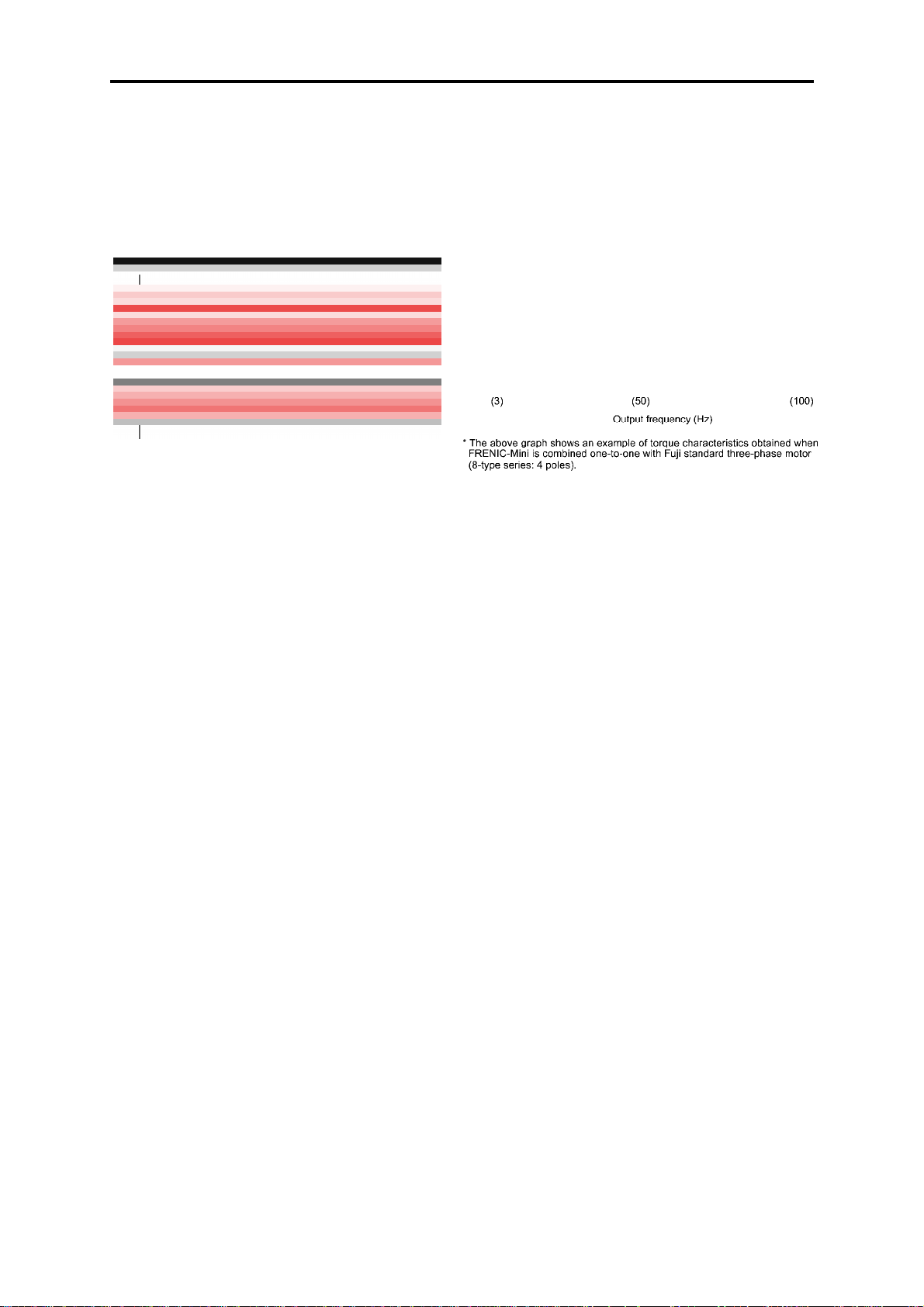
Optimum performance for traversing conveyors
• High starting torque, at 150% or more
Equipped with Fuji's original dynamic torque-vector control system and the automatic torque boost
function, these inverters ensure consistent and powerful operation (when automatic torque boost and
slip compensation control are ON and start frequency is set at 3 Hz).
Figure 1.1 Torque Characteristics Data
(Dynamic torque vector control: ON)
Figure 1.2 Example of Output Torque Characteristics
• Braking resistor connectable to the inverter
FRENIC-Mini series of inverters features a built-in braking transistor (for inverters of 0.4 kW (1/2
HP) or larger), which makes it possible for an opt ional braki ng resistor to be connecte d to increase t he
regenerative braking ability for conveya nce and transpor tation machin ery that req uires stro ng braking
power.
• Trip-free operation
The remarkably improved current limiting function (stall prevention) ensures trip-free operation even
for impact loads.
Figure 1.3 Example of Response for Impact Load Torque
• Stable operation even for a step load
The slip compensation function ensures stable operation even when the motor load fluctuates (step
load).
Figure 1.4 Example of Response for Step Load Torque (Refer to the note in Figure 1.2 for the test configuration.)
1-2
Page 19
• Inclusion of a brake signal makes it even more convenient
At brake release time
After the motor runs, the inverter detects torque generation and outputs signals.
1.1 Features
Chap. 1 INTRODUCTION TO FRENIC-Mini
At brake application time
Brake application that matches the timing can be done, so mechanical brake wear is reduced.
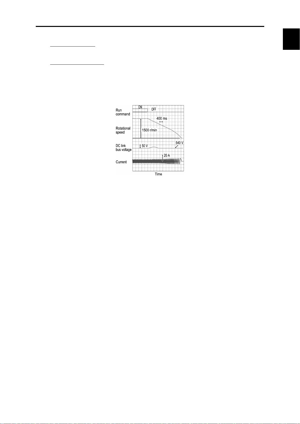
• Tripless deceleration by automatic deceleration control
The inverter controls the energy level generated and the deceleration time to decelerate to stop the
motor without tripping due to overvoltage.
Figure 1.5
Default functions for fans and pumps
• Automatic energy-saving function provided as standard
To minimize the total loss (motor loss plus inverter loss), rather than just the motor loss as in the
predecessor models, FRENIC-Mini saves even more power when used with fans or pumps.
Refer to Chapter 4, Section 4.7 "Drive Command Controller" for details.
* Energy savings vary depending on the motor characteristics.
Figure 1.6 Example of Energy Savings
1-3
Page 20

• PID control function
Permits motor operation while controlling temperature, pressure, or flow rate without using an
external device such as a temperature regulator. Under the constant pump discharge pressure control,
the slow flowrate stop function is available.
Refer to Chapter 4, Section 4.8 "PID Frequency Command Generator" for details.
• Cooling fan ON/OFF control function
The inverter's cooling fan can be turned off while the fan or pump is stopped for noise reduction and
energy savings.
The ideal functions to serve a multiplicity of needs for small-capacity inverters
• Compatible with a wide range of frequency settings
You can select the optimum frequency setti ng method that m atches your m achine or equipm ent via the
/
keypad (
1 to 5 V), 16 multistep speed settings (0 to 15 steps) or via RS-485 communications.
• A transistor output is provided
This enables an overload early warning, lifetime forecast or other information signals to be output
during operation.
Refer to function code E20 in Chapter 9, Section 9.2.2 " E codes (Extension terminal functio ns)."
• High output frequency - up to 400 Hz
The inverter can be used with equipment such as centrifugal separators that require a high motor speed.
In this case, you need to check whether the machine operation in combination with the motor is
compatible or not.
• Three points can be set for a non-linear V/f pattern.
The addition of an extra point (total 3 points) for the non-linear V/f pattern, which ca n be set as desired,
improves the FRENIC-Mini's drive capability, because the V/f pattern can be adjusted to match a
wider application area.
Refer to Chapter 4, Section 4.7 "Drive Command Controller" for details.
keys or potentiometer), analog input (4 t o 20 mA , 0 to 2 0 m A, 0 to +1 0 V , 0 to +5 V ,
Compact size
• Side-by-side mounting
More than one FRENIC-Mini inverter can be mounted side-by-side without any gap inside your
system control panel, thereby reducing the amount of space required for installation. (Ambient
temperature: 40°C (104°F) or lower)
Unit: mm (inch)
(Example: Inverters of 3-phase 200 V, 0.75 kW (1 HP) or less)
1-4
Page 21

• External dimensions compatible with Fuji FVR-C11S series,
externals compatible with original FRENIC-Mini series (FRNC1-)
The external differences (improved points) from the conventional FRNC1- are as
follows.
Screw added to the control circuit terminal bl ock cover, which prevents the cover from coming off due
to vibration or unexpected incident.
Control circuit terminal block using commonly used slotted screws instead of Phillips-head ones,
which standardizes tools.
1.1 Features
Chap. 1 INTRODUCTION TO FRENIC-Mini
Simplified operation and wiring
• Frequency setting potentiometer provided as standard
The frequency can be adjusted easily by hand.
• Easy-to-remove terminal block covers (for control circuit and main circuit) that are secured
with a single screw.
As shown below, the terminal block covers for the control circuit and main circuit can be removed
easily by removing the single screw from the control circuit terminal block cover.
Control circuit terminal block cover
Main circuit terminal
block cover
1-5
Page 22

• LED monitor on the keypad displaying all types of data
You can access and monitor all types of inverter's data and information including output frequency,
reference frequency, load shaft speed, output current, output voltage, alarm history, input power etc.
using built-in keypad with LED.
Refer to Chapter 3, "OPERATION USING THE KEYPAD."
• Menu mode accessible from the keypad
You can easily access the menu mode includi ng "Data s etting," "Data checki ng," "Drive m onit oring,"
"I/O checking," "Maintenance information," and "Alarm information."
Refer to Chapter 3, "OPERATION USING THE KEYPAD."
Maintenance
FRENIC-Mini series features the following facilities useful for maintenance.
Refer to Chapter 3, Section 3.3.5 "Reading Maintenance Information" and the FRENIC-Mini
Instruction Manual, Chapter 7 "MAINTENANCE AND INSPECTION" for details.
• The lifetime of the DC link bus capacitor (reservoir capacitor) can be estimated
The capacitor's condition compared with its initial state can be confirmed.
• Recording and displaying of cumulative running time of the inverter
The inverter records and displays the accumulated running time of the inverter itself, the printed
circuit board and cooling fan.
• Displaying Information that contributes to equipment maintenance
In addition to inverter maintenance information, the inverter displays data that also take equipment
maintenance into consideration.
Item Purpose
Motor cumulative
running time (hr)
The actual cumulative running time of the equipment (motor) using the inverter is
calculated.
<Example of use>
If the inverter is used to control a fan, this information is an indication of the timing
for replacing the belt that is used on the pulleys.
Number of starts
(times)
The number of the inverter start and stop times can be counted.
<Example of use>
The number of equipment start and stop times is recorded, so this information can
be used as a guideline for parts replacement timing in equipment in which starting
and stopping puts a heavy load on the machinery.
1-6
Page 23

1.1 Features
• Alarm history for up to 4 latest alarms
The inverter records detailed information for up to 4 alarms that occurred most recently, which can
also be displayed on the LED.
Refer to Chapter 3, Section 3.3.6 "Reading alarm information."
• Lifetime forecast signal via transistor output
This signal is output when the reserv oir capaci tor i n the DC link bus, the electrolytic capacit ors on the
printed circuit board, or the cooling fans have been nearing the end of their service life.
Refer to function code E20 in Chapter 9, Section 9.2.2 "E codes (Exte nsion term inal functions)"
for details.
Interface for peripheral devices and comprehensive protective functions
• All models are equipped with an inrush current suppression circuit.
FRENIC-Mini series features an inrush current suppression circ uit as standard in all m odels to reduce
the cost of peripheral devices such as input magnetic contactor.
• Terminals for a DC reactor (DCR) provided as standard
Terminals for connection of a DCR, which are necessary for suppressing harmonics, are provided as
standard in all models.
• Input/output phase loss protective function
FRENIC-Mini series can detect output phase loss at all times during starting and running. This fe ature
assists you for keeping operation of your system stable.
• Switchable sink/source
The input/output mode (sink/source) of the digital input terminals can be switched by means of an
internal jumper switch. No engineering change is required in other control devices including PLC.
• Motor can be protected by a PTC thermistor
The motor is protected by PTC (Positive Temperature Coefficient) thermistor which detects the
motor's temperature and stops the inverter before the motor is overheated.
Flexible through options
Chap. 1 INTRODUCTION TO FRENIC-Mini
• Function code copy function
The optional remote keypad inc ludes a built-in copy facility , so you can copy function code data set i n
a source inverter and duplicate it into a destination inverter.
• Inverter support software FRENIC Loader available
The inverter support loader program (Windows-base d), which sim plifies the configu ration of function
codes, is available as a free-of-charge option. It can be downloaded from our Website.
Refer to Chapter 5, "RUNNING THROUGH RS-485 COMMUNICATION" for details.
1-7
Page 24

• Optional USB-equipped remote keypad (Available soon)
A variety of data about the inverter unit can be saved in the keypad memory, allowing you to check the
information in any place.
Features
1. The keypad can be directly connected to a computer through
a commercial USB cable (mini B) without using a converter.
The computer can be connected online with the inverter.
USB
<Example of use in the office>
2. With the FRENIC Loader, the inverter can support the
following functions (1) to (4).
(1) Editing, co mparing, and copying the function code data
(2) Real-time operation monitor
(3) Trouble history (indicating the latest four troubles)
(4) Maintenance information
Data can be transferred from the USB port of the keypa d directly to the computer (FRENIC Loader) at
the site of production.
Periodical collection of life information can be carried out efficiently.
< Example of use at the site of production >
• Mounting on DIN rail
Using the rail-mounting base (option), t he inverter can ea sily be mounte d on a DIN rail (35 mm wide).
Refer to Chapter 6, "SELECTING PERIPHERAL EQUIPMENT" for details.
• Easy replacement of older models with new ones
Using the mounting adapter (optio n) m akes it possible t o m ount the la test m odels witho ut drilli ng any
additional holes.
Refer to Chapter 6, "SELECTING PERIPHERAL EQUIPMENT" for details.
1-8
Page 25

• Remote operation
Using the remote keypad (option) toget her with remote operation e xtension cable enables you to easily
operate the inverter from a remote location.
Refer to Chapter 5, "RUNNING THROUGH RS-485 COMMUNICATION" and Chapter 6,
"SELECTING PERIPHERAL EQUIPMENT" for details.
Wide variations
The wide range of models available in the FRENIC-Mini series of i nve rters is cert ain to fl exibly m eet
your various system needs.
• Three-phase 200/230 V series; 0.1 to 15 kW (1/8 to 20 HP)
• Three-phase 400/460 V series; 0.4 to 15 kW (1/2 to 20 HP)
• Single-phase 200/230 V series; 0.1 to 2.2 kW (1/8 to 3 HP)
• Single-phase 115 V series; 0.1 to 0.75 kW (1/8 to 1 HP)
• Model with a built-in EMC filter is available on order
Refer to Chapter 8, "SPECIFICATIONS" for details.
1.1 Features
Chap. 1 INTRODUCTION TO FRENIC-Mini
Global products
The FRENIC-Mini series of inverters is designed for use in global market in conformity with the
global standards listed below.
• All standard models conform to the EC Directive (CE Marking), UL standards (UL-Listed)
and Canadian standards (cUL-Listed).
All standard FRENIC-Mini inverters conform to European and North American/Canadian standards,
enabling standardization of the specifications for machines and equipment used at home and abroad.
• If a model with a built-in EMC filter is used, the model conforms to the European EMC
Directive.
1-9
Page 26
1.2 Control System
This section gives you a general overview of inverter control systems and features specific to the
FRENIC-Mini series of inverters.
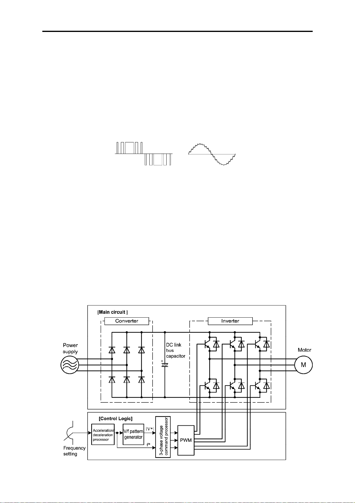
As shown in Figure 1.8, single- or three-phase commercial power is converted to DC power in the
converter section, which is then used to charge the capacitor on the DC link bus. Accor ding to co ntrol
commands or signals generated in the control logic, the inverter modulates the electricity charged in
the capacitor to PWM (Pulse Width Modulation) format and feeds the output to the motor. The
modulation frequency is called "carrier frequency." As shown in Figure 1.7, the voltage waveform of
the modulated power source produces pulse train with positive and negative polarity synchronized
with the inverter's output comm and frequ e ncy . The inverter feeds the produced output as drive power
with sinusoidal current waveform like that of ordinary commercial power lines.
PWM voltage waveform Current waveform
Figure 1.7 Output Voltage and Current Waveform of the Inverter
For the reference frequency given in the control logic, the accelerator/decelerator pr ocessor calculate s
the acceleration/deceleration rate required by run/stop control of the m otor and transfers the calc ulated
results to the 3-phase voltage command processor directly or via the V/f pattern generator.
Refer to Chapter 4, Section 4.7 "Drive Command Controller" for details.
The FRENIC-Mini series changes the voltage control from the "Simplified Torque-Vector Control"
using a magnetic flux estimator in conventiona l inverter series, to the Dynam ic Torque Vector Control
adopted in upper inverter series. Accordingly, the FRENIC-Mini series assures high start torque that
the conventional series cannot obtain, broadening the range of applications.
The control logic section, which is the very brain of the invert er, allows you to customize the i nverter's
driving patterns using the function code settings.
Refer to Chapter 4 "BLOCK DIAGRAMS FOR CONTROL LOGIC" for details.
Figure 1.8 Simplified Control System Diagram of FRENIC-Mini
1-10
Page 27
r
r
1.3 Recommended Configuration
1.3 Recommended Configuration
To control a motor with an inverter correctly, you should consider the rated capacity of both the m otor
and the inverter and ensure that the combination matches the specifications of the machine or system
to be used. Refer to Chapter 7, "SEL ECTING OPTIMAL MOTOR AND I NVERTER CAPACI TIES"
for details.
After selecting the rated capacity, select appropriate peripheral equipment for the inverter, then
connect them to the inverter.
Refer to Chapter 6, "SELECTING PERIPHERAL EQUIPMENT" and Chapter 8, Section 8.7
"Connection Diagrams" for details on the selection and connection of peripheral equipment.
Figure 1.9 shows the recommended configuration for an inverter and peripheral equipment.
Chap. 1 INTRODUCTION TO FRENIC-Mini
Three-phase or single-phase
power supply
Molded case circuit breaker
or
Earth leakage circuit breaker
(with overcurrent protection)
Magnetic contacto
Braking resistor
Moto
DC reactor (DCR)
Figure 1.9 Recommended Configuration Diagram
1-11
Page 28

Page 29

Chapter 2
PARTS NAMES AND FUNCTIONS
This chapter contains external views of the FRENIC-Mini series and an overview of terminal blocks,
including a description of the 7-segment LED monitor and keys on the keypad.
Contents
2.1 External V ie w and Terminal Blocks............................................................................................................2-1
2.2 Names and Functions of Keypad Components...........................................................................................2-2
Page 30

Page 31

r
2.1 External View and Terminal Blocks
2.1 External View and Terminal Blocks
(1) External view
Keypad
Nameplate
Control circuit terminal
bock cover
Main circuit
terminal block cover
Control circuit terminal
block cover
(2) Wiring section
Barrie
for the RS-485
communications port*
Control circuit wire
port
DB, P1, P (+) and
N (-) cable port
L1/R, L2/S, L3/T, U, V, W,
and grounding wire port
L1/R, L2/S, L3/T, P1, P (+),
and N(-) wire port
DB, U, V, W,
and grounding
wire port
(a) FRN0006C2S-2 (b) FRN0010C2S-2
(*When connecting the RS-485 communications cable, remove the control circuit terminal block cover and snip off the barrier
provided in it using nippers.)
Note: A box () in model names replaces A, C, E, or U depending on shipping destination.
Figure 2.1 External View of FRENIC-Mini
Cooling fan
Chap. 2 PARTS NAMES AND FUNCTIONS
Terminating resistor
ON/OFF jumper switch
Control circuit terminal block
Grounding terminal
RJ-45 connecotr
Power input terminal block
SINK/SOURCE jumper switch
DC reactor, braking resistor and
DC link bus terminal block
Grounding terminal
Inverter output terminal block
(FRN0010C2S-2)
Figure 2.2 Enlarged View of Terminal Blocks
The above figures show three-phase power source models. The term inal alloca tion of the power i nput
terminals L1/R, L2/S, L3/T, and grounding term inals for sing le-phase models differs from that show n
in above figures.
Refer to Chapter 8 "SPECIFICATIONS" for details on terminal functions, allocation and
connection and to Chapter 6, Section 6.2.1 "Recommended wires" when selecting wires.
For details on the keys and their functions, refer to Section 2.2 " LED Monitor, Potentiometer and
Keys on the Keypad." For details on keying operation and function code setting, refer to Chapter
3 "OPERATION USING THE KEYPAD."
2-1
Page 32

2.2 Names and Functions of Keypad Components
7-segment
As shown at the right, the keypad
consists of a four-digit, 7-segment
LED monitor, a potentiometer (POT),
and six keys.
The keypad allows you to run and stop
the motor, monitor running status,
configure the function code data,
check I/O signal states, and display
maintenance information and alarm
information.
Table 2.1 Overview of Keypad Functions
Program/Reset key
LED monitor
Down key Up key Function/Data key
Figure 2.3 Keypad
PotentiometerRUN key
STOP key
Monitor, Potentiometer
and Keys
/
Functions
Four-digit, 7-segment LED monitor which displays the running status, data
settings, and alarm status of the inverter according to the operation modes*.
In Running mode, the monitor displays running status information (e.g.,
output frequency, current, and voltage). In Programming mode, it displays
menus, function codes and their data. In Alarm mode, it displays an alarm
code which identifies the error factor if the protective function is activated.
Potentiometer (POT) which is used to manually set frequency, auxiliary
frequencies 1 and 2 or PID process command.
RUN key. Press this key to run the motor.
STOP key. Press this key to stop the motor.
UP/DOWN keys. Press these keys to select the setting items and change the
function data displayed on the LED monitor.
Program/Reset key. Press this key to switch the operation modes* of the
inverter.
Pressing this key in Running mode switches the inverter to Programming
mode and vice versa.
In Alarm mode, pressing this key after removing the error factor will switch
the inverter to Running mode.
Function/Data key.
Pressing this key in Running mode switches the information displayed
(output frequency (Hz), current (Amps) or voltage (V)).
Pressing this key in Programming mode displays the function code and sets
the data entered using
keys or the POT.
/
Pressing this key in Alarm mode displays information concerning the alarm
code currently displayed on the LED monitor.
* FRENIC-Mini features three operation modes--Running, Programming, and Alarm modes. Refer to
Chapter 3, Section 3.1 "Overview of Operation Modes."
2-2
Page 33

LED monitor
2.2 Names and Functions of Keypad Components
In Running mode, the LED monitor displays running status information (output frequency, current or
voltage); in Programming mode, it displays menus, function codes and their data; in Alarm mode, it
displays an alarm code which identifies the error factor if the protective function is activated.
If one of LED4 through LED1 is blinking, it means that the cursor is at this digit, allowing you to
change it.
If the decimal point of LED1 is blinking, it means that the currently displayed data is a PID process
command, not the frequency data usually displayed.
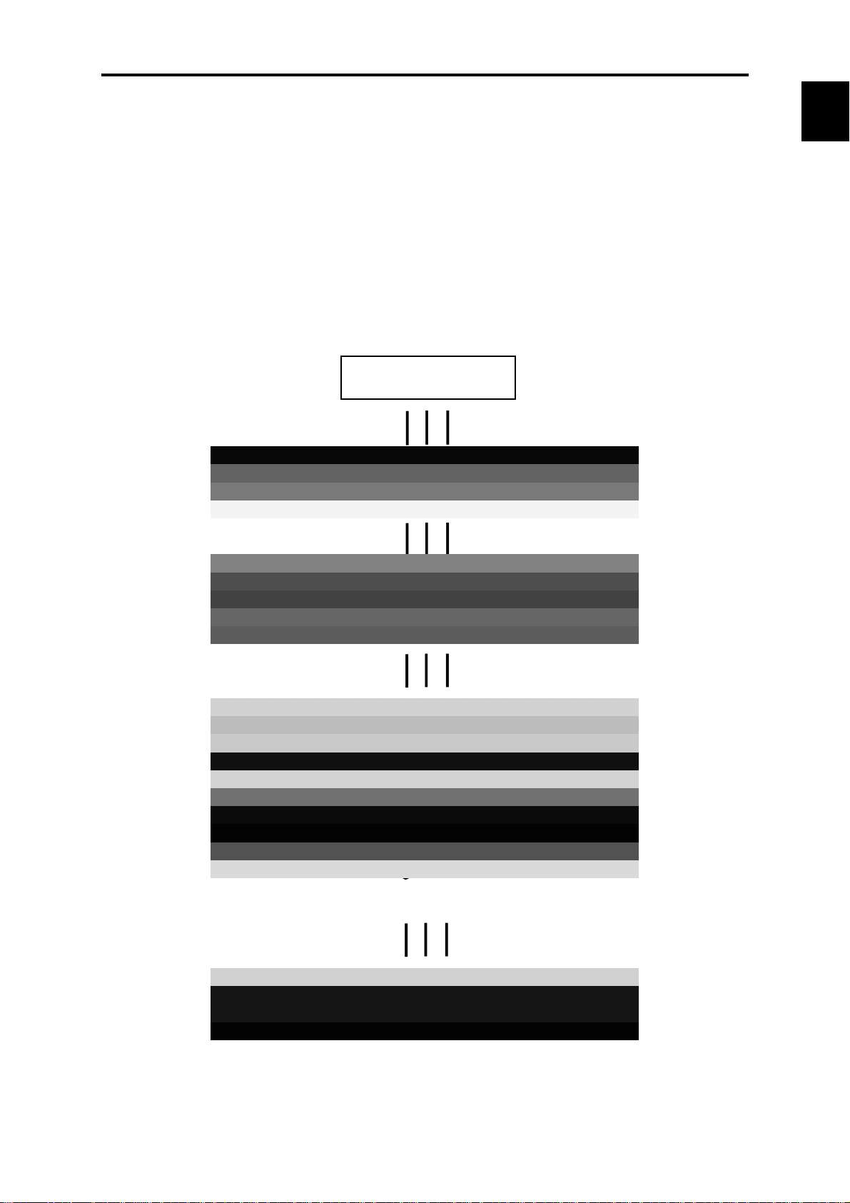
Table 2.2 Alphanumeric Characters on the LED Monitor
Character 7-segment Character 7-segment Character 7-segment Character 7-segment
0
1
2
3
0
1
2
3
9
A
b
C
LED4 LED3 LED2 LED1
Figure 2.4 7-Segment LED Monitor
9
Aa
b
Cc
i
J
K
L
i
Jj
-
Ll
S
T
u
r
r
Ss
-
-
Chap. 2 PARTS NAMES AND FUNCTIONS
4
5
6
7
8
Special characters and symbols (numbers with decimal point, minus and underline)
0. - 9.
4
5
6
7
8
0
. – 9. - - _ _
d
E
F
G
H
d
Ee
Ff
Gg
Hh
M
n
o
P
q
n
o
Pp
q
V
W
X
y
Z
u
-
y
-
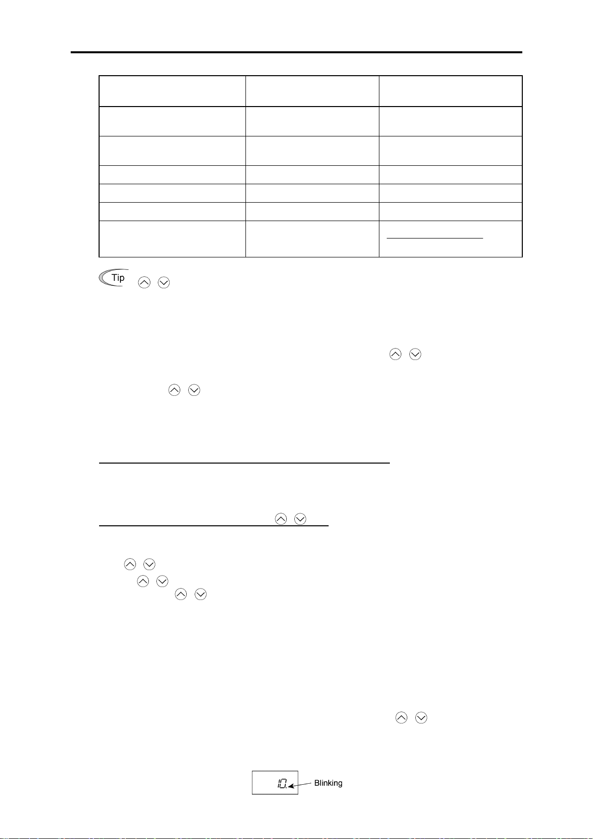
Repeat function of / keys
/ keys have a repeat function which helps you change displayed data speedily as follows:
Usually you press
If you hold down
/ keys once to increase or decrease the displayed value by 1, respectively.
either key so as to activate the repeat function, the displayed value will keep
changing in steps of 1 speedily. Note that when changing some function code data during running of
the inverter (not always possible), the displayed data will keep c hanging more slowly. This is to ensure
safe and stable operation.
2-3
Page 34
Continuous holding-down function for Program/Reset key
Holding down the key longer (approx. one second or longer) moves the cursor on th e LED monitor.
In Running mode, the cursor moves alon g digits; in Programm ing mode, it moves not only along digits
but to the next function code.
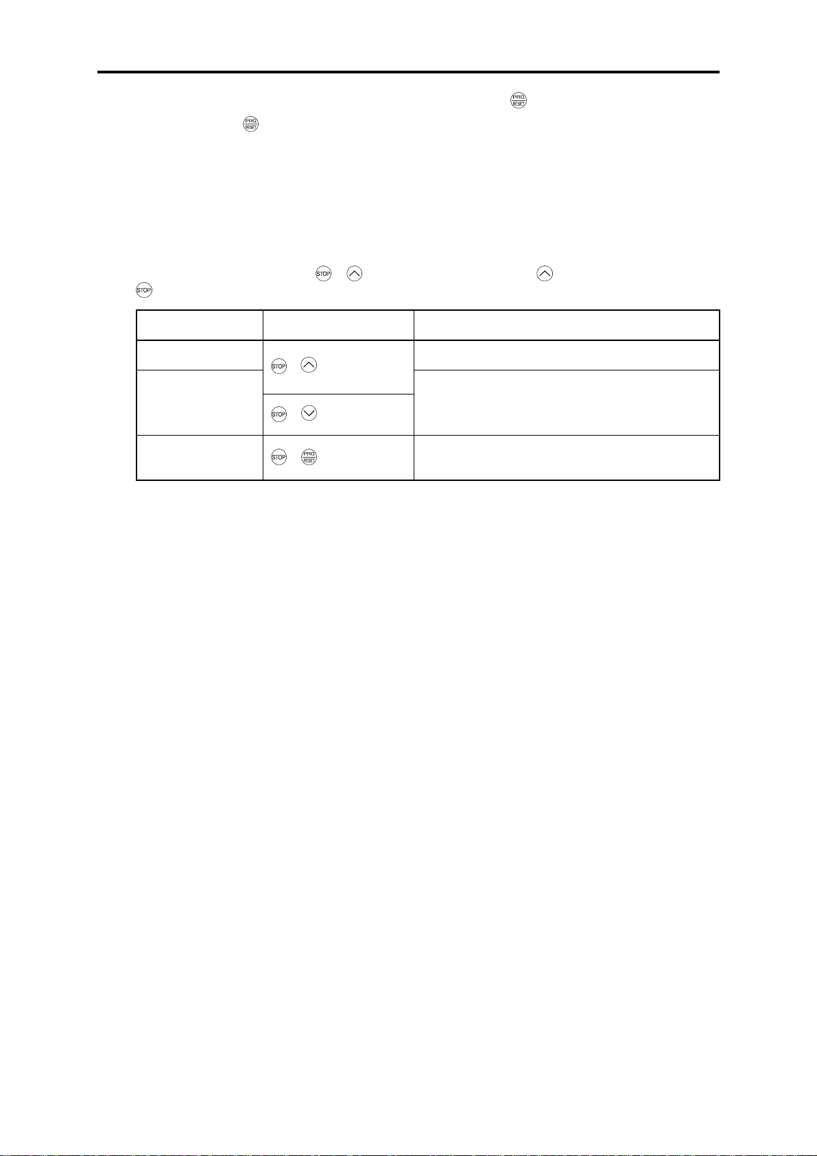
Simultaneous keying
Simultaneous keying means depressing two keys at the same time (expressed by "+"). FRENIC-Mini
supports simultaneous keying as listed below.
(For example, the expression "
+ keys" stands for pressing the key while holding down the
key.)
Operation modes Simultaneous keying Used to:
Running mode Control entry to/exit from jogging operation.
Programming mode
Alarm mode + keys
+ keys
+ keys
Change special function code data.
(Refer to function codes F00, H03, H45 and H97 in
Chapter 9 "FUNCTION CODES.")
Switch to Programming mode without clearing
alarms.
About changing of function code data
The function code data can be changed only when the data value displayed on the LED monitor is
flashing.
When the data value is lit, no change is allowed. To change the data, stop the inverter or disable the
data protection.
2-4
Page 35

Chapter 3
OPERATION USING THE KEYPAD
This chapter describes inverter operation using the keypad. The inverter features three operation modes
(Running, Programming and Alarm modes) which enable you to run and stop the motor, monitor running
status, set function code data, display run ning i nform ation require d for m aintena nce, an d dis play a larm data.
Contents
3.1 Overview of Operation Modes....................................................................................................................3-1
3.2 Running Mode ............................................................................................................................................3-3
3.2.1 Run/stop the motor.............................................................................................................................. 3-3
3.2.2 Set up the reference frequency and PID process command................................................................3-3
3.2.3 Monitor the running status.................................................................................................................. 3-5
3.2.4 Jog (inch) the motor............................................................................................................................ 3-7
3.3 Programming Mode....................................................................................................................................3-8
3.3.1 Setting the function codes--"Data Setting"..........................................................................................3-9
3.3.2 Checking changed function codes--"Data Checking".......................................................................3-13
3.3.3 Monitoring the running status--"Drive Monitoring".........................................................................3-14
3.3.4 Checking I/O signal status--"I/O Checking".....................................................................................3-17
3.3.5 Reading maintenance information--"Maintenance Information"
3.3.6 Reading alarm information--"Alarm Information"............................................................................3-24
3.4 Alarm Mode..............................................................................................................................................3-28
3.4.1 Releasing the alarm and transferring the inverter to Running mode................................................. 3-28
3.4.2 Displaying the alarm history............................................................................................................. 3-28
3.4.3 Displaying the running information when an alarm occurs..............................................................3-29
3.4.4 Transferring to Programming mode..................................................................................................3-29
........................................................3-21
Page 36

Page 37

3.1 Overview of Operation Modes
3.1 Overview of Operation Modes
FRENIC-Mini features the following three operation modes:
Running mode : This mode allows you to enter run/stop commands in regular operation. You
may also monitor the running status in realtime.
Programming mode : This mode allows you to set function code data and check a variety of
information relating to the inverter status and maintenance.
Alarm mode : If an alarm occurs, the inverter automatically enters this Alarm mode in
which the corresponding alarm code* and its related information may be
displayed on the LED monitor.
* Alarm code: Shows the error factor that has activated the protective function. For
details, refer to Chapter 8, Section 8.8 "Details of Protective Functions."
Figure 3.1 shows the status transition of the inverter between these three operation modes. If the
inverter is turned ON, it automatically enters Running mode, making it possible to start or stop the
motor.
To make the transition between th ose op eratio n m odes, y ou ne ed to pre ss the sp ecifie d key s as s hown
below, except at the occurrence of an alarm. If an alarm occurs in Running mode, the inverter will
automatically switch to Alarm mode.
Chap. 3 OPERATION USING THE KEYPAD
Figure 3.1 Status Transition between Operation Modes
3-1
Page 38

The figure below shows the transi tion between the runnin g status monitoring screens in Ru nning mode,
that between the menu screens in Programming mode, and that between the alarm code screens in
Alarm mode.
*1 The speed monitor may display the outp ut f r e que nc y (Hz), reference f reque nc y (Hz), load shaft spe ed (r /min), line
speed (m/min.), and constant feeding rate time (min.) which can be selected by setting up function code E48.
*2 These PID-related information will appear only when the inverter is under the PID control. (Refer to Section 3.2.2.)
*3 This appears only when timer operation is enabled by setting up function code C21. (Refer to Chapter 9, Section
9.2.3 "C codes (Control functions of frequency).")
*4 This appears only when the remote keypad (option) is connected with the inverter.
Figure 3.2 Basic Screen Transition in Each Operation Mode
3-2
Page 39

3.2 Running Mode
3.2 Running Mode
If the inverter is turned ON, it automatically enters Running mode in which you may:
(1) Run/stop the motor
(2) Set up the reference frequency and PID process command
(3) Monitor the running status (e.g., output frequency, output current)
(4) Jog (inch) the motor
3.2.1 Run/stop the motor
By factory default, pressing the key starts running the motor in the forward direction and pressing
key brings the motor to a decelerated stop. The key is enabled only in Running mode.
the
Changing function code F02 data makes it possible to run the motor in the reverse direction by
pressing the
and control the motor by pressing
key, determine the motor rotational direction by entering i nput signals to the term inals,
/
keys.
Chap. 3 OPERATION USING THE KEYPAD
3.2.2 Set up the reference frequency and PID process command
By using the potentiometer and
frequency and PID process command. It is also possib le to set up the reference frequency as frequency,
load shaft speed, line speed, and constant feeding rate time by setting function code E48.
Setting up the reference frequency
With the potentiometer on the keypad (factory default)
If you set function code F01 to "4: Potentiom eter on the keypad" (factory default) a nd select frequency
setting-1 with function codes E01 through E03 (Hz2/Hz1 = OFF), then the potentiometer becomes
enabled to set up the reference frequency. Setting function code C30 to "4: Potentiometer on the
keypad" and selecting frequency setting-2 (Hz2/Hz1 = ON) also produce the same effect.
With
If you set function code F01 to "0: Keypad operation" and select frequency setting-1, then
keys become enabled to set up the reference frequency in Running mode. In any other operation
modes, those keys remain disabled.
Pressing
keys again makes it possible to change the reference frequency. The new setting will be saved
internally. Even if the inverter is switched to any other frequency entry method and then returned to
the keypad entry method, the setting will be retained.
Further, even turning OFF the inverter will automatically save the setting into the non-volatile
memory. At the next time when the inverter is turned ON, the setting will become the default
frequency.
/ keys
/
keys calls up the reference frequency with the lowest dig it blinking. Pressi ng
keys on the keypad, you may set up the desired reference
/
/
/
If you set function code F01 to "0: Keypad operation" but do not select frequency setting-1, then
keys cannot be used for setting up the reference frequency. Pressing those keys will just display the
currently selected reference frequency.
To set up the reference frequency from any other d isplayed items, it is depe ndent on function code E48
data (= 4, 5, or 6) "LED monitor details (Select speed monitor)" as listed in the following table.
3-3
/
Page 40
E48 data "LED monitor details
(Select speed monitor)"
Display of reference frequency Conversion of displayed value
0: Output frequency (before slip
compensation)
1: Output frequency (after slip
compensation)
2: Reference frequency Frequency setting
4: Load shaft speed Load shaft speed setting Frequency setting x E50
5: Line speed Line speed setting Frequency setting x E50
6: Constant feeding rate time Constant feeding rate time
Frequency setting
Frequency setting
E50
×
If you set function code C30 to "0: Keypad operation" and select frequency setting-2, then
/
keys become also enabled to set up the reference frequency.
Setting up the PID process command
To enable PID control, you need to set function code J01 to 1 or 2.
/
In the PID control mode, the items that can be set or checked with
keys are different from
those under normal frequency control, depending upon the current LED monitor setting. If the LED
monitor is set to the speed monitor (E43 = 0), you may access manual feed commands (Reference
/
frequency) with
keys; if it is set to any other, you may access PID process commands with
those keys.
Refer to Chapter 4, Section 4.8 "PID Frequency Command Generator" for details on the PID
control.
Setting the PID process command with the built-in potentiometer
Set function code E60 to "3: PID process command 1" and J02 to " 1: PID process comm and 1." After
that, selecting PID control remote process command enables you to set the PID process command
using the built-in potentiometer.
E39 settingFrequency
Setting the PID process command with
/ keys
Set function code J02 to "0: Keypad operation" and set the LED monitor to the setting other than the
speed monitor (E43 = 0) in Running mode. This makes it possible to set the PID process command
using
Pressing
monitor. Pressing
/ keys. This setting is possible only in Running mode.
keys displays the PID process command with the lowest digit blinking on the LED
/
/ keys again makes it possible to change the PID process command. Once the
PID process command is modified, it will be saved internally. Even if the inverter is switched to any
other PID process command entry method and then returned to the keypad entry method, the setting
will be retained.
Further, even turning OFF the inverter will automatically save the setting into the non-volatile
memory. At the next time when the inverter is turned ON, the setting will become the default PID
process command.
Even if the PID process command is selected ((SS4) = ON) in the multistep frequency, it is still
possible to set the process command using the keypad.
When function code J02 has been set to any value except 0, pressing
/ keys displays the PID
process command currently selected (setting is not possible).
When the PID process command is displayed, the decimal point next to the lowest digit on the LED
display blinks to discriminate it from the frequency setting.
3-4
Page 41

3.2 Running Mode
• When setting the frequency and others with
will blink. Change the setting, starting from the lowest digit and the cursor will move
/
keys, the lowest digit on the display
gradually to the next digit to be changed.
• When the data is to be changed rapidly, hold down the
key for 1 second or longer, and
the blinking cursor will move to the next digit where the data can be changed (cursor
movement).
3.2.3 Monitor the running status
In Running mode, the nine items listed below can be monitored. Immediately after the inverter is
turned ON, the monitor item specified by function code E43 is displayed. Press the key to switch
between monitor items.
Table 3.1 Monitor Items
Chap. 3 OPERATION USING THE KEYPAD
Monitor Items
Speed monitor
(Hz, r/min, m/min, min)
Output current (A)
Input power (kW)
Output voltage (V) *2
PID command *3 *4
PID feedback value *3 *5
PID output *3 *4
Timer (sec) *3
Input watt-hour
Display Sample on
the LED monitor *
5*00
!90a
Current output from the inverter in RMS
*40p
Input power to the inverter
200u
Voltage output from the inverter in RMS
1*0*
)0*
10**
50
Remaining effective timer count
2*38
1
Refer to Table 3.2.
(PID command or PID feedback value) × (PID
display coefficient A – B) + B
PID display coefficient A and B: Refer to function
codes E40 and E41
PID output in %, assuming the maximum frequency
(F03) as 100%
Display value =
Meaning of Displayed Value
Input watt-hour (kWh)
100
*1 A display value 10000 or above cannot be displayed on the 4-digit LED monitor, so " " appears instead.
u
*2 When the LED monitor displays an output voltage, the 7-segment letter
the voltage "V."
*3 These items appear only under PID control (J01 = 1 or 2).
The timer (for timer operation) appears only when timer operation is enabled (C21 = 1).
When the PID control or timer operation is disabled, "----" appears instead.
*4 When the LED monitor displays a PID command or its output amount, the dot (decimal point) attached to the
lowest digit of the 7-segment letter blinks.
*5 When the LED monitor displays a PID feedback amount, the dot (decimal point) attached to the lowest digit of the
7-segment letter lights.
in the lowest digit stands for the unit of
3-5
Page 42

Figure 3.3 shows the procedure example for selecting the desired monitor item.
*1 The speed monitor may display the output frequency (Hz), reference frequency (Hz), load shaft speed (r/min), line
speed (m/min.), and contrast feeding rate time (min.) which can be selected by setting up function code E48.
*2 These PID-related information will appear only when the inverter is under the PID control. (R efer to Section 3.2.2.)
*3 This will appear only when timer operation is enab led by setting up function code C2 1. (Refer to Chapter 9, Section
9.2.3 "C codes (Control functions of frequency).")
Figure 3.3 Monitor Item Selection Example
3-6
Page 43

3.2 Running Mode
Table 3.2 lists the display items for the speed monitor that can be chosen with function code E48.
Table 3.2 Display Items on the Speed Monitor
Speed monitor items Function code E48 data Meaning of Displayed Value
Output frequency (before
slip compensation) (Hz)
(Factory default)
Output frequency (after slip
compensation) (Hz)
Reference frequency (Hz) 2 Final reference frequency
Load shaft speed (r/min) 4 Display value = Output frequency (Hz) x E50*
Line speed (m/min) 5 Display value = Output frequency (Hz) x E50*
Constant feeding rate time
(min)
*
Output frequencies contained in these formulas are output frequencies before slip compensation.
0 Pre-slip compensation frequency
1 Frequency actually being outputted
6
Display value =
E50
3.2.4 Jog (inch) the motor
In Running mode, pressing + keys at the same time (simultaneous keying) can make the
inverter ready for jogging. The
To return the inverter from the ready-to-jog state to the usual running state, you need to press
keys simultaneously.
Using the external input signal command (JOG) also allows the transition between the ready-to-jog
state and usual running state.
Refer to function codes E01 to E03 in Chapter 9, Section 9.2.2 "E codes (Extension terminal
functions)" for details.
j0g
appears on the LED monitor.
Chap. 3 OPERATION USING THE KEYPAD
*
E39frequency Output
×
+
During jogging, the jogging frequency (C20) and acceleration/deceleration time for jogging (H54)
will apply. They are exclusively prepared for jogging and required to be set up individually.
When jogging the motor from the keypad, the inverter will only run while the
and contrarily the moment the
key is released, the inverter will decelerate and stop the motor.
key is held down,
The transition ( + keys) between the ready-to-jog state and usual running state is
enabled only when the inverter is not in operation.
3-7
Page 44

3.3 Programming Mode
Pressing the key in Running mode switches the inverter to Programming mode. This mode
provides the following functions which can be easily selected with the menu-driven system.
(1) Data setting (Menu #1)
(2) Data checking (Menu #2)
(3) Drive monitoring (Menu #3)
(4) I/O checking (Menu #4)
(5) Maintenance information (Menu #5)
(6) Alarm information (Menu #6)
(7) Data copying (Menu #7) (only when an option is mounted)
The table below lists the menus, letters that will appear on the LED monitor, and functions. The
leftmost digit (numerals) of each letter string indicates the corresponding menu number and the
remaining three digits indicate the menu contents.
When the inverter enters Programming mode from the second time on, the menu that was select ed last
in Programming mode will be displayed.
Table 3.3 Menus Available in Programming Mode
Menu
Menu #1
"Data setting"
Menu #2
"Data checking"
Menu #3
"Drive
monitoring"
Menu #4
"I/O checking"
LED monitor
shows:
!f__
!e__
!c__
!p__
P codes (Motor 1 parameters)
!h__
!a__
A codes (Moto r 2 parameters)
!j__
J codes (Application functions)
!y__
y codes (Link functions)
"rep
#ope
$i_o
Main functions Refer to:
F codes (Fundamental functions)
E codes
(Extension terminal functions)
C codes
(Control functions of frequency)
H codes
(High performance functions)
Displays only function codes that have been
changed from their factory defaults. You may refer
to or change those function codes data.
Displays the running information required for
maintenance or test running.
Displays external I/O signal information. Section
Selecting
each of these
function
codes enables
its data to be
displayed/
changed.
Section
3.3.1
Section
3.3.2
Section
3.3.3
3.3.4
Menu #5
"Maintenance
information"
Menu #6
"Alarm
information"
Menu #7
"Data copying"
%che
&al
'cpy
Displays maintenance information including
cumulative running time.
Displays the latest four alarm codes. You may refer
to the running information at the time when the
alarm occurred.
Allows you to read or write function code data, as
well as verifying it.
NOTE: To use this function, a remote keypad
(option) is required.
3-8
Section
3.3.5
Section
3.3.6
Page 45
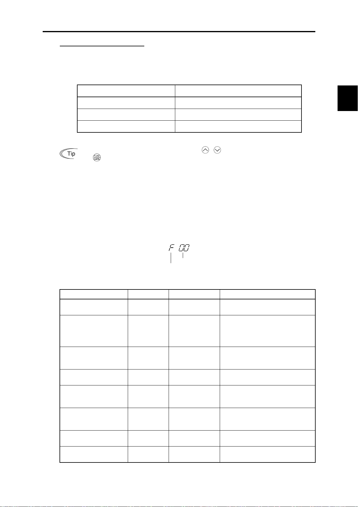
3.3 Programming Mode
Limiting menus to be displayed
The menu-driven system has a limiter function (specified by function code E52) that limits menus to
be displayed for the purpose of simple operation. The factory default is to display Menu #1 "Data
setting" only, allowing no switching to any other menu.
Function Code E52 – Menu Display Mode for Keypad
Function code data (E52) Menus selectable
0: Function code data setting mode Menu #1 "Data setting" (factory default)
1: Function code data check mode Menu #2 "Data checking"
2: Full-menu mode Menu #1 through #6 (#7*)
* Menu #7 appears only when the remote keypad (option) is mounted.
If the full-menu mode is selected, pressing the / keys will cycle through menus. With
the key, you may select the desired menu. Once all of the menus have been cycled
through, the display will return to the first menu.
Chap. 3 OPERATION USING THE KEYPAD
3.3.1 Setting the function codes--"Data Setting"
Menu #1 "Data setting" in Programming mode allows you to set function codes for making the
inverter functions match your needs.
The table below lists the function codes available in the FRENIC-Mini. The function codes are
displayed on the LED monitor on the keypad as shown below.
ID number in each function code group
Function code group
Table 3.4 List of FRENIC-Mini Function Codes
Function code group Function code Function Description
F codes
(Fundamental functions)
E codes
(Extension terminal
functions)
C codes
(Control functions of
frequency)
P codes
(Motor parameters)
H codes
(High performance
functions)
A codes
(Alternative motor
functions)
J codes
(Application functions)
y codes
(Link functions)
Refer to Chapter 9 "FUNCTION CODES" for details on the function codes.
F00 to F51 Basic functions To be used for basic motor running.
E01 to E99 Terminal functions
C01 to C52 Control functions
P02 to P99 Motor 1 parameters
H03 to H98
A01 to A 52 Motor 2 parameters
J01 to J72
y01 to y99 Link functions To be used for communications.
High level
functions
Application
functions
To be used to select the functions of
the control circuit terminals.
T o be used to set functions related to
the LED monitor display.
T o be used to set application functions
related to frequency settings.
T o be used to set specific parameters
for the motor capacity, etc.
To be used for high added value
functions and complicated control,
etc.
T o be used to set specific parameters
for the motor capacity, etc.
To be used for PID control and brake
signals.
3-9
Page 46

Function codes that require simultaneous keying
To change data for function codes F00 (Data Protection) and H03 (Data Initialization), simultaneous
keying operation is necessary--
+ keys or + keys. This prevents data from being lost by
mistake.
Changing, validating, and saving of function code data during running
Some function code data can be changed while the motor is running and some cannot. Further,
amongst the function codes w hose da ta ca n be ch anged w hile t he m otor is runni ng, there are some for
which the changes can be validated immediately and others for which they cannot. Refer to the
"Change when running" column in Chapter 9, Section 9.1 "Function Code Tables."
3-10
Page 47

3.3 Programming Mode
Figure 3.4 shows the status transition for Menu #1 "Data setting" and Figure 3.5 shows an example of
the function code data changing procedure.
Chap. 3 OPERATION USING THE KEYPAD
Figure 3.4 Status Transition Diagram for "Data Setting"
3-1 1
Page 48

Figure 3.5 Example of Function Code Data Changing Procedure
Basic key operation
This section will give a description of the basic key operation, following the example of the function
code data changing procedure shown in Figure 3.5.
This example shows you how to change function code F01 data from the factory default of
/
"Potentiometer operation on the keypad (F01 = 4)" to "
(1) With the menu displayed, use
example, select
(2) Press the
example, function code
!f__
).
key to display the function codes in the funct ion cod e gro up s elec ted i n (1). (In this
f00
/ keys to select the desired function code group. (In this
will appear.)
keys operation (F01 = 0)."
Even if the function code list for a particular function code group is displayed, it is possible to
transfer the display to a different function code group using
(3) Select the desired function code using
function code
f01
.)
/ keys and press the key. (In this example, select
The data of this function code will appear. (In this example, data
(4) Change the function code data using
/ keys. (In this example, press the key four times
/
keys.
4
of
f01
will appear.)
to change data from 4 to 0.)
(5) Press the
The
saue
key to establish the function code data.
will appear and the data will be saved in the non-volatile memory. The display will
return to the function code list, then move to the next function code. (In this example,
f02
.)
Pressing the
key before the key cancels the change made to the data. The data reverts to
the previous value, the display returns to the function code list, and the original function code
reappears.
(6) Press the
key to return to the menu from the function code list.
Cursor movement: You may move the cursor also when changing function code data in the
same way as with the frequency settings. Refer to Section 3.2.2 "Set up the reference
frequency and PID process command."
3-12
Page 49
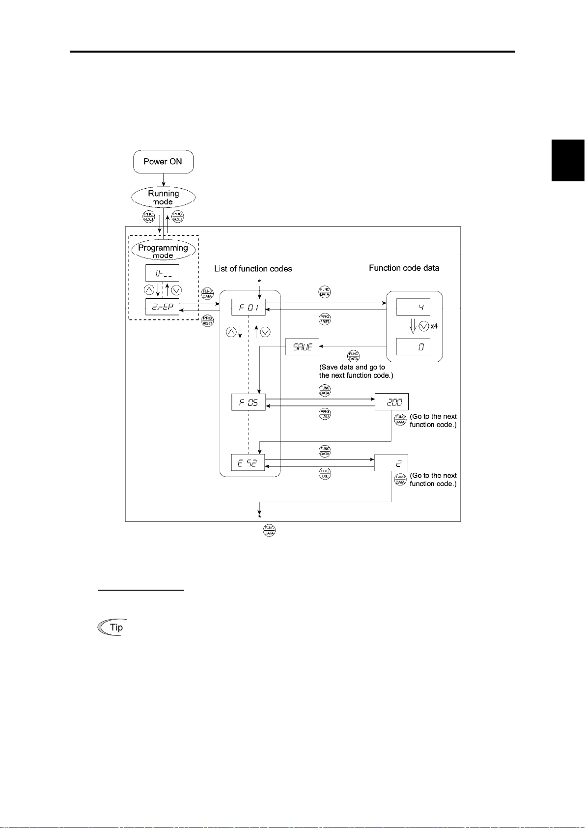
3.3 Programming Mode
3.3.2 Checking changed function codes--"Data Checking"
Menu #2 "Data checking" in Programming mode allows you to check function code data that have
been changed. Only data that has been changed from the factory defaults are displayed on the LED
monitor. You may refer to the function code data and change again if necessary. Figure 3.6 shows the
status transition diagram for "Data checking."
Chap. 3 OPERATION USING THE KEYPAD
* Pressing the key when the e 52 data is displayed will take you back to f 01.
Figure 3.6 Data Checking Status Transition Diagram (Changes made only to F01, F05, E52)
Basic key operation
The basic key operation is the same as for Menu #2 "Data setting."
To monitor Menu #2 "Data checking," it is necessary to set function code E52 data to 1
(Function code data check mode) or 2 (Full-menu mode).
3-13
Page 50
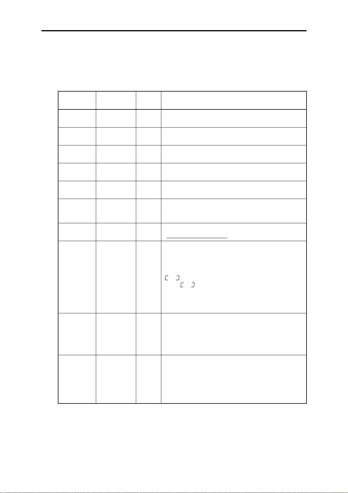
3.3.3 Monitoring the running status--"Drive Monitoring"
Menu #3 "Drive monitoring" is used to c heck the runni ng st atus durin g m ainten ance a nd tes t r unni ng.
The display items for "Drive monitoring" are listed in Table 3.5. Using keys, you may check those
items in succession. Figure 3.7 shows the status transition diagram for "Drive monitoring."
Table 3.5 Drive Monitoring Display Items
LED monitor
shows:
3_00
3_01
3_02
3_03
3_05
3_06
3_07
3_09
Contents Unit Description
Output
frequency
Output
frequency
Output
current
Output
voltage
Reference
frequency
Rotational
direction
Running
status
Load shaft
speed
(line speed)
Hz Output frequency before slip compensation
Hz Output frequency after slip compensation
A Present output current
V Present output voltage
Hz Present reference frequency
N/A
N/A
r/min
(m/min)
Displays the rotational direction specified by a run
command being outputted.
f
: forward; r: reverse, – – – –: stop
Displays the running status in hex. format. Refer to
"Displaying running status
The unit for load shaft speed is r/min and that for line speed
is m/min.
Display value = (Output frequency Hz before slip
compensation) × (Function code E50)
is displayed for 10000 (r/min or m/min) or more.
When
means that the function code should be reviewed. For
example:
Load shaft speed = Displayed data × 10 (r/min)
is displayed, the data is overflowing, which
" on the page 3-16.
3_10
3_11
PID process
commands
PID feedback
value
N/A
N/A
These commands are displayed through the use of function
code E40 and E41 (PID display coefficient A and B).
Display value = (PID process command) × (PID display
coefficient A - B) + B
If PID control is disabled, "– – – –" appears.
This value is displayed through the use of function code
E40 and function code E41 (PID display coefficient A and
B).
Display value = (PID feedback value) × (PID display
coefficient A - B) + B
If PID control is disabled, "– – – –" appears.
3-14
Page 51
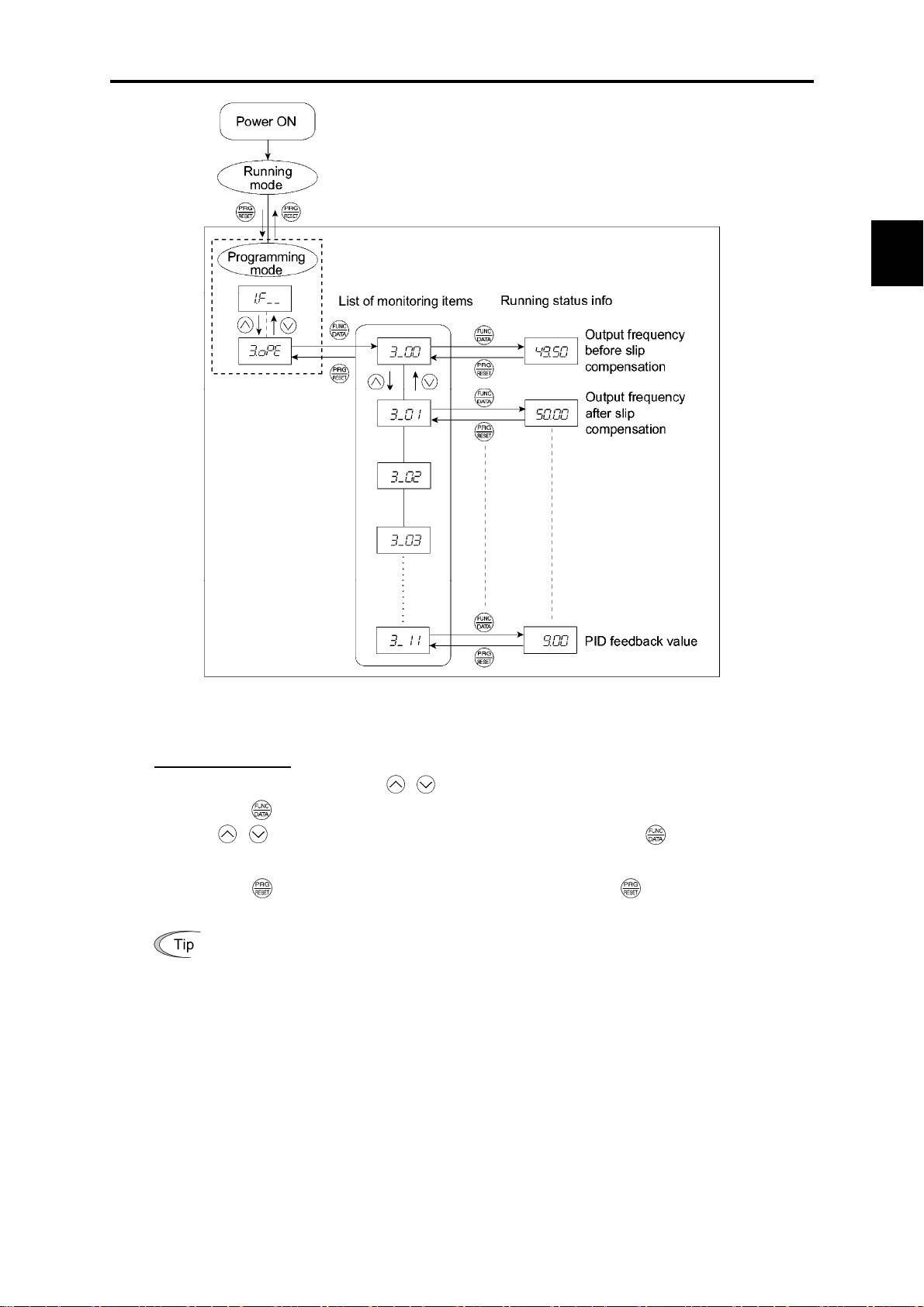
3.3 Programming Mode
Chap. 3 OPERATION USING THE KEYPAD
Figure 3.7 Drive Monitoring Status Transition
Basic key operation
(1) With the menu displayed, use
(2) Press the key to display the desired code in the monitoring items list (e.g.
(3) Use
/ keys to select the desired monitoring item, then press the key.
/ keys to select "Drive monitoring" (
#ope
).
3_00
The running status information for the selected item will appear.
(4) Press the key to return to the monitoring items list. Press the key again to return to the
menu.
If the menu cannot switch to any other one, set function code E52 to 2 (Full-menu mode).
).
3-15
Page 52
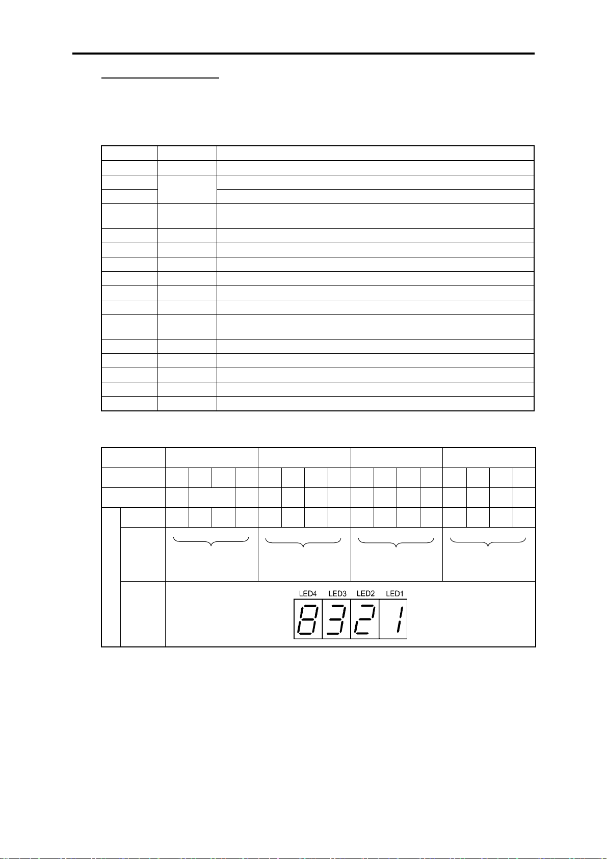
Displaying running status
To display the running status in hexadecimal format, each state has been assigned to bit 0 to 15 as
listed in Table 3.6. Table 3.7 shows the relationship between each of the status assignments and the
LED monitor display. Table 3.8 gives the conversion table from 4-bit binary to hexadecimal.
Table 3.6 Running Status Bit Allocation
Bit Notation Content
15 BUSY 1 when function code data is being written.
14 Always 0.
13
12 RL 1 when co mmunications is effective (when run commands and set frequencies
11 ALM 1 when an alarm has occurred.
10 DEC 1 during deceleration.
9 ACC 1 during acceleration.
8 IL 1 during current limitation.
7 VL 1 under voltage control.
6 TL Always 0.
5 NUV 1 when DC link bus voltage has increased up to the specified level (0 for
4 BRK Always 0.
3 INT 1 when the inverter output is shut down.
2 EXT 1 during DC braking.
1 REV 1 during running in the reverse direction.
0 FWD 1 during running in the forward direction.
WR
Always 0.
commands are issued via communications).
undervoltage).
Table 3.7 Running Status Display
LED No. LED4 LED3 LED2 LED1
Bit 15 14 13 12 11 10 9 8 7 6 5 4 3 2 1 0
Notation BUSY WR RL ALM DEC ACC IL VL TL NUV BRK INT EXT REV FWD
Binary 1 0 0 0 0 0 1 1 0 0 1 0 0 0 0 1
Hexa-
decimal
(See Tabl e
3.8.)
Example
Hexa-
8
3
2
1
decimal
on the
LED
monitor
3-16
Page 53

3.3 Programming Mode
Hexadecimal expression
A 16-bit binary number is expressed in hexadecimal format (4 bits). Table 3.8 shows the expression
corresponding to decimals. The hexadecimals are shown as they appear on the LED monitor.
Table 3.8 Binary and Hexadecimal Conversion
Binary Hexadecimal Decimal Binary Hexadecimal Decimal
0 0 0 0
0 0 0 1
0 0 1 0
0 0 1 1
0 1 0 0
0 1 0 1
0 1 1 0
0 1 1 1
0
1
2
3
4
5
6
7
0 1 0 0 0
1 1 0 0 1
2 1 0 1 0
3 1 0 1 1
4 1 1 0 0
5 1 1 0 1
6 1 1 1 0
7 1 1 1 1
8
9
a
b
c
d
e
f
8
9
10
11
12
13
14
15
3.3.4 Checking I/O signal status--"I/O Checking"
With Menu #4 "I/O checking," you may disp lay the status of external I/O signals without using a
measuring instrument. External signals that can be disp layed include digit al I/O signals and a nalog I/O
signals. Table 3.9 lists check items available. The status transition for I/O checking is shown i n Figure
3.8.
Table 3.9 I/O Check Items
Chap. 3 OPERATION USING THE KEYPAD
LED monitor
shows:
4_00
4_01
4_02
4_03
4_04
Display contents Description
I/O signals on the
control circuit
terminals
I/O signals on the
control circuit
terminals under
communication
control
Input voltage on
terminal [12]
Input current on
terminal [C1]
Output voltage to
analog meters
[FMA]
Shows the ON/OFF state of the digital I/O terminals. Refer to "[1]
Displaying control I/O signal terminals" on page 3-19 for details on
the display contents.
Shows the ON/OFF state for the digital input terminals that received
a command via RS-485 communications. Refer to "[1] Displaying
control I/O signal terminals" on page 3-19 and "[2] Displaying
control I/O signal terminals under communication control" on page
3-20 for details on the display contents.
Shows the input voltage on terminal [12] in volts (V).
Shows the input current on terminal [C1] in milliamperes (mA).
Shows the output voltage on terminal [FMA] in volts (V).
3-17
Page 54
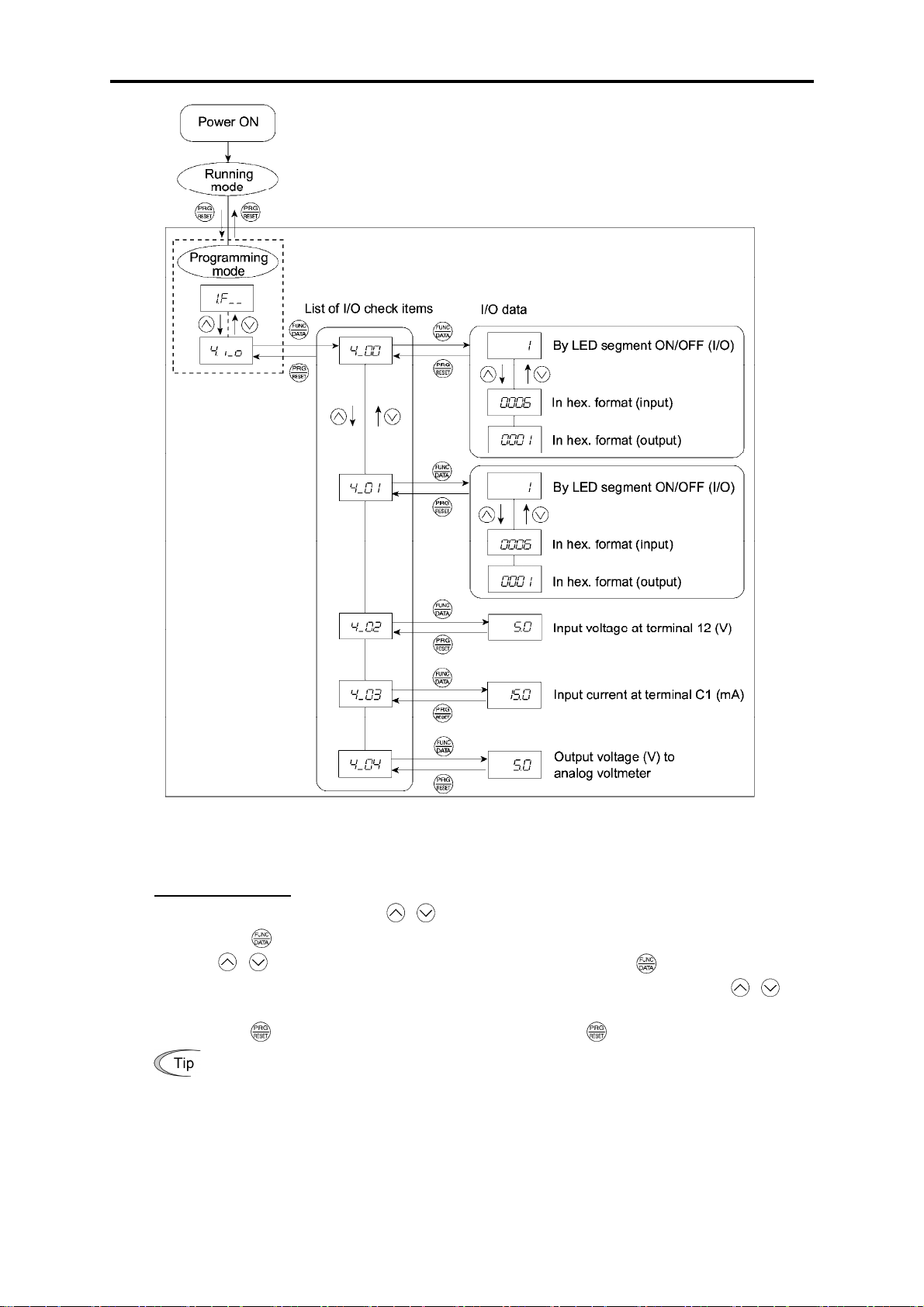
Figure 3.8 Status Transition of I/O Check
Basic key operation
(1) With the menu displayed, use
/ keys to select "I/O check"(
$i_o
(2) Press the key to display the codes for the I/O check item list. (e.g.
(3) Use
/ keys to select the desired I/O check item, then press the key.
The corresponding I/O check data will appear. For control circuit I/O terminals, use
to select one of the two different display methods.
(4) Press the
If the menu cannot switch to any other one, set function code E52 to 2 (Full-menu mode).
key to return to the I/O check item list. Press the key again to return to the menu.
)
4_00
)
/ keys
3-18
Page 55

3.3 Programming Mode
[ 1 ] Displaying control I/O signal terminals
The I/O signal status of control circuit terminals m ay be disp layed with O N/OFF of the LED segm ent
or in hexadecimal display.
Display I/O signal status with ON/OFF of the LED segment
As shown in Table 3.10 and the figure below , segments "a" to "e" on LED 1 light when the digital in put
terminals ([FWD], [REV], [X1], [X2], a nd [X3]) are s hort-cir cuited ( ON ) with the t erm inal [CM] and
do not light when they are opened (OFF). Segment "a" on LED3 lights when the circuit between
output terminal [Y1] and terminal [Y1E] is closed (ON) and does not light when the circuit is open
(OFF). LED4 is for terminals [30A], [30B], [30C]. Segment "a" on LED4 lights when the circuit
between terminals [30C] and [30A ] are short-circ uited (O N) and do es not l ight w hen th ey are opened.
This LED monitor displays hardware terminal information, which means that it may not light
when it is in reverse logic (refer to Chapter 9 "FUNCTION CODES" for details), even when
it is active.
Table 3.10 Segment Display for External Signal Information
Segment LED4 LED3 LED2 LED1
Chap. 3 OPERATION USING THE KEYPAD
a [30A/B/C] [Y1]–[Y1E] –
b – – –
[FWD]–[CM] or
[FWD]–[PLC]
[REV]–[CM]or
[REV]–[PLC]
c – – –
d – – –
e – – –
f – – (XF)
g – – (XR)
dp
*1
(XF), (XR), and (RST) are reserved for communications. Refer to "[ 2 ] Displaying control
I/O signal terminals under communication control."
*2
Terminal [CM] if the jumper switch is set for a sink; terminal [PLC] if the jump er switch is
set for a source.
– – (RST)*1 –
– : No correlating control circuit terminals
[X1]–[CM] or
[X1]–[PLC]
[X2]–[CM] or
[X2]–[PLC]
[X3]–[CM] or
[X3]–[PLC]
*1
–
*1
–
*2
*2
*2
*2
*2
3-19
Page 56
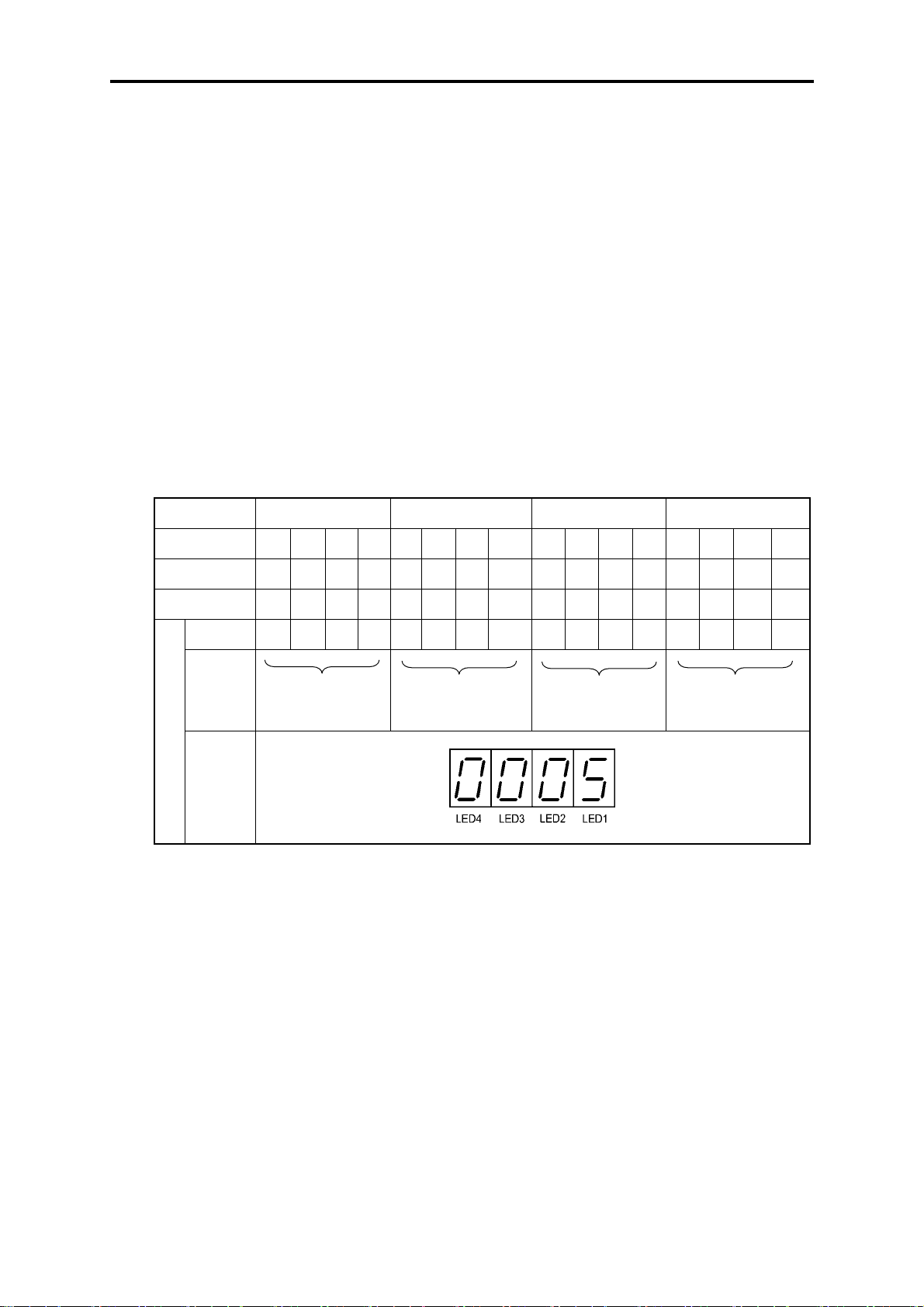
Displaying I/O signal status in hexadecimal format
Each I/O terminal is assigned to bit 15 through bit 0 as listed in Table 3.11. An unassigned bit is
interpreted as "0." Allocated bit data is displayed on the LED monitor in 4-digit hexadecimals ("0" to
"F" each).
With the FRENIC-Mini, digital input terminals [FWD] and [REV] are assigned to bit 0 and bit 1,
respectively. Terminals [X1] through [X3] are assigned to bits 2 through 4. The value "1" is set for
each bit when the assigned input terminal is short-circuited (ON) with terminal [CM]. The value "0"
when it opens (OFF). For example, when [FWD] and [X1] are ON and all others are OFF, the display
on LED4 to LED1 would be 0005.
Bit 0 is assigned to digital output terminal [Y1]. The value "1" is set when the terminal is
short-circuited with [Y1E], and the value "0" is set when it opens. The status of the mechanical relay
contact output terminal [30A], [30B] and [30C] are assigned to bit 8. The value "1" is set when the
circuit between output terminals [30A] and [30C] is clos ed and the value "0" when the circuit between
[30B] and [30C] is closed. For example, if [Y1] is ON and the circuit between [30A] and [30C] are
short-circuited with each other, then the display for LED4 to LED1 would be 0101.
How the hexadecimal display is configur ed for the term inals to whic h bits 0 to 15 are assig ned and the
7-segment LED is shown below.
Table 3.11 Segment Display for I/O Signal Status in Hexadecimal Format
LED No. LED4 LED3 LED2 LED1
Bit 15 14 13 12 11 10 9 8 7 6 5 4 3 2 1 0
Input terminal (RST)* (XR)* (XF)* - - - - - - - - [X3] [X2] [X1] [REV] [FWD]
Output terminal
Binary 0 0 0 0 0 0 0 0 0 0 0 0 0 1 0 1
Hexa-
decimal
(See Tabl e
3.8.)
Hexa-
Example
decimal
on the
LED
monitor
* (XF), (XR), and (RST) are reserved for communications. Refer to "[ 2 ] Displaying control I/O signal terminals under
communication control" below.
- - - - - - -
0
0
[30A/C]
- - - - - - - [Y1]
0
– : No correlating control terminals
5
[ 2 ] Displaying control I/O signal terminals under communication control
There are two control circuit input displays under communications link control – "display with
ON/OFF of the LED segment" and "in hexadecimal format" for input commanded from RS-485
communications link. The content is similar to that of the control circuit I/O signal terminal status
display; however, (XF) and (XR) are added as inputs and nothing is assigned as output terminals.
Refer to the RS-485 Communication User's Manual (MEH448) for details on command inputs
through RS-485 communication.
3-20
Page 57

3.3 Programming Mode
3.3.5 Reading maintenance information--"Maintenance Information"
Menu #5 "Maintenance information" in Programming mode contains information necessary for
performing maintenance on the inverter. Table 3.12 lists the maintenance information display items
and Figure 3.9 shows the status transition for maintenance information.
LED monitor
shows:
5_00
5_01
5_03
5_04
5_05
5_06
5_07
5_08
5_09
Table 3.12 Maintenance Display Items
Display contents Description
Accumulated run
time
DC link bus
voltage
Max. temperature
of heat sink
Max. effective
current
Capacitance of the
DC link bus
capacitor
Accumulated run
time of electrolytic
capacitors on the
printed circuit
boards
Accumulated run
time of the cooling
fan
Number of startups The motor run times (the number of times the inverter run command
Input watt-hour Shows the input watt-hour of the inverter.
Shows the accumulated power-ON time of the inverter.
Unit: 1,000 hours
When the count is less than 10,000 hours (display: 0.001 to 9.999), it
is possible to check data in units of hours.
When the count is 10,000 hours or more (display: 10.00 to 65.53), the
display will change to units of 10 hours. When it exceeds 65,535
hours, the count will be reset to "0" and start over again.
Shows the DC link bus voltage of the inverter.
Unit: V (volts)
Shows the maximum temperature of the heat sink for every hour.
Unit: ºC
Shows the maximum effective current for every hour.
Unit: A (amperes)
Shows the current capacitance of the DC link bus capacitor, based on
the capacitance when shipped as 100%. Refer to the FRENIC-Mini
Instruction Manual, Chapter 7 "MAINTENANCE AND
INSPECTION" for details.
Unit: %
Shows the accumulated time during which a voltage is applied to the
electrolytic capacitors on the printed circuit boards.
Unit: 1,000 hours (Display range: 0.01 to 99.99)
When the count is less than 99,990 hours (Display: 0.01 to 99.99), it is
possible to check data in units of 10 hours (0.01).
When the count exceeds 99,990 hours, it stops and the LED monitor
sticks to 99.99.
Shows the accumulated run time of the cooling fan.
If the cooling fan ON/OFF control (function code H06) is enabled, the
time when the fan is stopped is not counted.
Unit: 1,000 hours (Display range: 0.01 to 99.99)
When the count is less than 99,990 hours (Display: 0.01 to 99.99), it is
possible to check data in units of 10 hours (0.01).
When the count exceeds 99,990 hours, it stops and the LED monitor
sticks to 99.99.
is set to ON) are calculated and displayed.
1.000 indicates 1,000 times. When any number ranging from 0.001 to
9.999 is displayed, the count increases by 0.001 per startup, and when
any number from 10.00 to 65.53 is displayed, the count increases by
0.01 every 10 startups.
If the count exceeds 65,535, it will be reset to "0" and start over again.
Unit: 100 kWh (Display range: 0.001 to 9999)
Depending on the value of input watt-hour, the decimal point on the
LED monitor shifts to show it within the LED monitors’ resolution
(Display resolution: 0.001 → 0.01 → 0.1 → 1).
To reset the integrated input watt-hour and its data, set function code
E51 to "0.000."
When the count exceeds 1,000,000 kWh, it will be reset to "0."
Chap. 3 OPERATION USING THE KEYPAD
3-21
Page 58

Table 3.12 Maintenance Display Items (Continued)
LED monitor
shows:
5_10
5_11
5_12
5_14
5_16
5_23
5_31
5_35
Display contents Description
Input watt-hour
data
No. of RS-485
errors
RS-485 error
contents
Inverter's ROM
version
Keypad's ROM
version
Accumulated run
time of motor
Remaining time
before the next
motor 1
maintenance
Remaining startup
times before the
next maintenance
Shows the value expressed by "input watt-hour (kWh) × E51 (whose
data range is 0.000 to 9,999)."
Unit: None.
(Display range: 0.001 to 9999. The data cannot exceed 9999. (It will
be fixed at 9,999 once the calculated value exceeds 9999.))
Depending on the value of integrated input watt-hour data, the
decimal point on the LED monitor shifts to show it within the LED
monitors’ resolution.
To reset the integrated input watt-hour data, set function code E51 to
"0.000."
Shows the total number of errors that have occurred in RS-485
communication after the power is turned ON.
Once the count exceeds 9.999, it will be reset to "0."
Shows the latest error that has occurred in RS-485 communication in
decimal format.
For error contents, refer to the RS-485 Communication User's Manual
(MEH448).
Shows the inverter's ROM version as a 4-digit code.
Shows the keypad's ROM version as a 4-digit code. (Available only
when an optional remote keypad is connected.)
Shows the content of the accumulated run time of motor.
The display method is the same as for "Accumulated run time"
(
5_00
).
Shows the time remaining before the next maintenance, which is
estimated by subtracting the cumulative run time of motor 1 from the
maintenance interval specified by H78. (This function applies to
motor 1 only.)
0
to
9999
Display range:
Time remaining before the next maintenance (hour) =
Displayed value × 10
Shows the startup times remaining before the next maintenance,
which is estimated by subtracting the number of startups from the
preset startup count for maintenance specified by H79. (This function
applies to motor 1 only.)
The display method is the same as for
The x10 LED turns ON.
5_08
above.
3-22
Page 59

3.3 Programming Mode
Chap. 3 OPERATION USING THE KEYPAD
Figure 3.9 Status Transition of Maintenance Information
Basic key operations
(1) With the menu displayed, use / keys to select "Maintenance information" (
(2) Press the
(3) Use
/ keys to select the desired maintenance item, then press the key.
key to display the list of maintenance item codes (e.g.
5_00
).
%che
).
The data of the corresponding maintenance item will appear.
(4) Press the key to return to the list of maintenance items. Press the key again to return to the
menu.
If the menu cannot switch to any other one, set function code E52 to 2 (Full-menu mode).
3-23
Page 60

3.3.6 Reading alarm information--"Alarm Information"
Menu #6 "Alarm information" in Programming mode shows the cause of the past 4 alarms as alarm
codes. Further, it is also possible to display alarm information that indicates the status of the inverter
when the alarm occurred. Table 3.13 shows the contents of the alarm information and Figure 3.10
shows the status transition of the alarm information.
Table 3.13 Alarm Information Contents
LED monitor
shows: (Item No.)
6_00
6_01
6_02
6_03
6_04
6_05
6_06
6_07
6_08
Display contents Description
Output frequency Output frequency before slip compensation
Output current Present output current
Output voltage Present output voltage
Calculated torque Calculated motor output torque
Reference frequency Present reference frequency
Rotational direction This shows the rotational direction of a run command being
output.
f
: forward; r: reverse; – – – –: stop
Running status This shows the running status as a hexadecimal display. Refer
to Displaying running status
running status."
Accumulated
running time
No. of startups The motor run times (the number of times the inverter run
Shows the cumulative power-ON time of the inverter.
Unit: thousands of hours. When the total ON time is less than
10,000 hours (display: 0.001 to 9.999), it is possible to check
data in hourly units. When the total time is 10,000 hours or
more (display: 10.00 to 65.53), the display will change to units
of 10 hours. When the total time exceeds 65,535 hours, the
display returns to 0 and the count will start again.
command is set to ON) are calculated and displayed.
1.000 indicates 1,000 times. When any number from 0.001 to
9.999 is displayed, the display increases by 0.001 per startup,
and when any number from 10.00 to 65.53 is displayed, the
display increases by 0.01 every 10 startups.
in Section 3.3.3 "Monitoring the
6_09
6_11
6_12
6_13
6_14
6_15
6_16
DC link bus voltage Shows the DC link bus voltage of the inverter's main circuit.
Unit: V (volts)
Max. temperature of
heat sink
Terminal I/O signal
status (displayed
with the ON/OFF of
LED segments)
Terminal input signal
status (in
hexadecimal format)
Terminal output
signal status (in
hexadecimal display)
No. of consecutive
occurrences
Overlapping alarm 1 Simultaneously occurring alarm codes (1)
Shows the maximum temperature of the heat sink.
Unit: ºC
Shows the ON/OFF status of the digital I/O terminals. Refer to
Section 3.3.4 "[1] Displaying control I/O signal terminals" for
details.
This is the number of times the same alarm has occurred
consecutively.
(– – – – is displayed if no alarms have occurred.)
3-24
Page 61

3.3 Programming Mode
Table 3.13 Alarm Information Contents (Continued)
LED monitor
shows: (Item No.)
6_17
6_18
6_19
6_20
6_21
6_22
Display contents Description
Overlapping alarm 2 Simultaneously occurring alarm codes (2)
(– – – – is displayed if no alarms have occurred.)
Terminal I/O signal
status under
communication
control (displayed
with the ON/OFF of
LED segments)
Terminal input signal
status under
communication
control (in
hexadecimal format)
Terminal output
signal status under
communication
control (in
hexadecimal display)
Error sub code Secondary error code for the alarm.
Running status 2 Shows the running status 2 in hexadecimal format. For details,
Shows the ON/OFF status of the digital I/O terminals under
RS-485 communication control. Refer to Section 3.3.4 "[2]
Displaying control I/O signal terminals under communication
control" for details.
see the table below.
Chap. 3 OPERATION USING THE KEYPAD
6_24
Running status 3 Shows the running status 3 in hexadecimal format. For details,
see the table below.
When the same alarm occurs a number of times in succession, the alarm information for the
first time is retained and the information for the following alarms is not updated.
Table 3.14 Running Status 2 (
Bit Content Bit Content
Drive motor type
15
14 6
13 5
12 4
11 3
10 2
0: Induction motor,
1: Permanent magnet synchronous motor
(Not used.)
9
Rotation direction limitation
8
0: Enable, 1: Disable
6_22
) Bit Assignment
7
1
0
(Not used.)
Motor selection
00: Motor 1
01: Motor 2
Inverter drive control
0000: V/f control with slip compensation
inactive
0001: Dynamic torque vector control
0010: V/f control with slip compensation
active
3-25
Page 62

Table 3.15 Running Status 3 (
Bit Notation Content Bit Notation Content
15 - (Not used.) 7 - (Not used.)
14 ID2 Current detected 2 6 - (Not used.)
13 IDL Low current detected 5 OL Motor overload early warning
12 ID Current detected 4 IPF
11 OLP Overload prevention control 3 SWM2 Motor 2 selected
10 LIFE Lifetime alarm 2 - (Not used.)
9 OH
8 TRY Auto-resetting 0 FAR Frequency arrival signal
Heat sink overheat early
warning
6_24
) Bit Assignment
Auto-restarting after momentary
power failure
1 FDT Frequency detected
3-26
Page 63

3.3 Programming Mode
Chap. 3 OPERATION USING THE KEYPAD
Figure 3.10 Status Transition of Alarm Information
Basic key operations
(1) With the menu displayed, use
(2) Press the
/ keys to select "Alarm information" (
key to display the alarm list code (e.g.
!0l1
).
&al
).
In the list of alarm codes, the alarm information for the last 4 alarms will be saved as an alarm
history.
(3) Each time / keys are pressed, the last four alarms are displayed in order from the most
recent one as "
(4) Press the
(e.g.
6_00
second each. It is possible to display the ite m number (e.g.
!
", """, "#" and "$".
key while the alarm code is displayed, and the corresponding alarm item number
) and data (e.g. Output frequency) will be displayed continuously in turn for 1
6_01
) and data (e.g . Output current)
for each desired alarm using / keys.
(5) Press the
If the menu cannot switch to any other one, set function code E52 to 2 (Full-menu mode).
key to return to the alarm list. Press the key again to return to the menu.
3-27
Page 64

3.4 Alarm Mode
When the protective function is activated to issue an alarm, the inverter automatically transfers to
Alarm mode and the alarm code will appear in the LED monitor. Figure 3.11 shows the status
transition of Alarm mode.
Figure 3.11 Status Transition of Alarm Mode
3.4.1 Releasing the alarm and transferring the inverter to Running mode
Remove the cause of the alarm and press the key to release the alarm and return to Running mode.
The
key is enabled only when the alarm code is displayed.
3.4.2 Displaying the alarm history
It is possible to display the most recent 3 alarm codes in addition to the one currently displayed.
Previous alarm codes can be displayed by pressing
displayed.
/ keys while the current alarm code is
3-28
Page 65

m
3.4 Alarm Mode
3.4.3 Displaying the running information when an alarm occurs
If an alarm occurs, you may check various running status information (output frequency and output
current, etc.) by pressing the key when the alarm code is displayed. The item number and data for
each running information is displayed in alternation.
Further, you can switch between the various running information using
information is the same as for Menu #6 "Alarm information" in Programming mode. Refer to Table
3.13 in Section 3.3.6 "Reading alarm information."
Pressing the
key while the running information is displayed returns th e display t o the alarm codes.
Pressing the key continuously a number of times while the running information is
displayed after removing the cause of the alarm will cause the inverter to transit to the a lar
code display, and the next alarm to be released. If a run command had been input at this
stage, the motor will start up.
/ keys. Detailed running
3.4.4 Transferring to Programming mode
Further, it is also possible to transfer the inverter to Programming mode by pressing + keys
simultaneously while the alarm is displayed and to then check and adjust the function code data.
Chap. 3 OPERATION USING THE KEYPAD
3-29
Page 66

Page 67

Chapter 4
BLOCK DIAGRAMS FOR CONTROL LOGIC
This chapter describes the main block diagram s for the control logic of the FRENIC-Mini series of inverters.
Contents
4.1 Symbols Used in the Block Diagrams and their Meanings.........................................................................4-1
4.2 Drive Frequency Command Generator.......................................................................................................4-2
4.3 Drive Command Generator......................................................................................................................... 4-4
4.4 Terminal Command Decoders.....................................................................................................................4-6
4.5 Digital Output Selector.............................................................................................................................4-10
4.6 Analog Output (FMA) Selector................................................................................................................4-12
4.7 Drive Command Controller.......................................................................................................................4-13
4.8 PID Frequency Command Generator........................................................................................................4-16
Page 68

Page 69
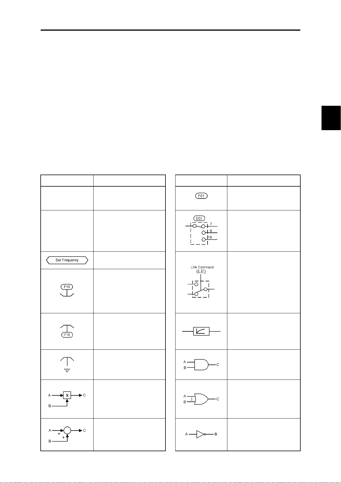
4.1 Symbols Used in the Block Diagrams and their Meanings
FRENIC-Mini inverters are equipped with a num ber of function codes to m atch a variety of m otor operations
required in your system. Refer to Chapter 9 "FUNCTION CODES" for details of the function codes.
The function codes have functional relationship with each other. Several special function codes also work
with execution priority with each other depending upon their data settings.
This chapter contains the main block diagr am s for contr ol l ogic i n the i nverter a nd de scribes th e relati onship
between the inverter's logic and fun ction c odes. It is im portant to fu lly u nderstand this relationshi p a nd to set
the function code data correctly.
The block diagrams contained in the chapter show only function codes having mutual relation. For the
function codes that work stand-alone and for details of individual function codes, refer to Chapter 9
"FUNCTION CODES."
4.1 Symbols Used in the Block Diagrams and their
Meanings
Table 4.1 lists the symbols commonly used in the block diagrams and their meanings with some examples.
Table 4.1 Symbols and Meanings
Symbol Meaning Symbol Meaning
Chap. 4 BLOCK DIAGRAMS FOR CONTROL LOGIC
[FWD],[Y1]
(etc.)
(FWD),(REV)
(etc.)
Input/output signals to/from
the inverter's control
terminal block.
Control commands assigned
to the control terminal block
input signals.
Internal control command
for inverter logic.
High limiter: Limits peak
value by a constant or by
data set to the function code.
Low limiter: Limits the
bottom value by a constant
or by data set to the function
code.
Zero limiter: Keeps data
from dropping to a negative
value.
Function code.
Switch controlled by a
function code. Numbers
assigned to the terminals
express the function code
data.
Switch controlled by an
internal control command. In
the example shown at the
left, the link operation
command (LE) is assigned to
one of the digital input
terminals from [X1] to [X3],
which then controls the
switch.
Low-pass filter: Features
appropriate characteristics
by changing the time
constant through the
function code data.
AND logic: In normal logic
systems, only if A = ON and
B = ON, then C = ON.
Otherwise, C = OFF.
Gain multiplier for set
frequencies given by current
and/or voltage input or for
analog output signals.
C = A × B
Adder for 2 signals or
values. C = A + B
If B is negative then C = A –
B.
4-1
OR logic: In normal logic
systems, if any inputs are
ON, then C = ON. Only if all
inputs are OFF, then C =
OFF.
NOT logic: In normal logic
systems, if A = ON, then B =
OFF and vice versa.
Page 70
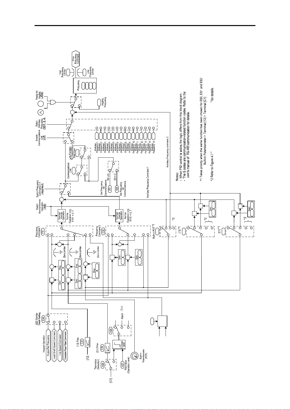
4.2 Drive Frequency Command Generator
F15
STOP
+
+
+
F16
C01
C02
C03
Jump
+
+
y99
H30
0,2
C04
C20
C05
C06
C07
C08
C09
C10
C11
C12
C13
C14
C15
C16
C17
C18
C19
PID Frequency Command Generator
0,2
1,3
1,3
C34C32
×
×
×
C39
×
C37
0, 1, 2
0
1
+
+
+
×
456
C50
F18
C32 C34
0
3
012
E60
4
0
2
3
7
4
1
+
C50
+
+
×
+
+
F18
C37 C39
F18 C50
×
0
×
1, 2
2
+
+
C34C32
×
" "
Motor overheat
detected by
0
thermistor
1
2
7
3
C39
C37
THM
UP/
H61
DOWN
Control
UP/DOWN Control
(Initial frequency setting)
UP
UP (Increase
output frequency)
DOWN (Decrease
output frequency)
E61
DOWN
3
1
2
0
5
E62
1
2
3
5
Figure 4.1 Block Diagram for Drive Frequency Command Generator
4-2
Page 71

4.2 Drive Frequency Command Generator
Figure 4.1 shows the processes that generate the final drive frequency command from the frequency settings
given by various means and those switched/modified by function codes. If PID process control takes effect
(J01=1 or 2), the drive frequency generation will differ from that shown in this diagram. (Refer to Section 4.8
"PID Frequency Command Generator.")
Additional and supplemental information is given below.
- Frequency settings using the
key on the keypad may take a different format by means of the data
/
setting for function code E48. Refer to function code E48 in Chapter 9 "FUNCTION CODES" for details.
- [C1] input as a frequency settings signal will always be interpreted as "0" when the current input signal
terminal [C1] is specified for the thermistor (H26 = 1, 2).
- Settings for both gain and bias will take effect concurrently only for frequency setting 1 (F01). For
frequency setting 2 (C30) and auxiliary frequency settings 1 and 2 (E60 to E62), only the gain will take
effect.
- Gain for the built-in potentiometer cannot be changed by any function code or other means.
- Switching between normal and inverse operation is only effective for frequency setting from the analog
input signal (terminal [12], [C1] or built-in potentiometer). Frequency settings from the
/
key are
only valid for normal operation.
- The command formats for frequency settings by S01 and S05 for the communications link facility take a
different form, as follows:
- S01: the setting range is –32768 to +32767, where the maximum output frequency is obtained at
±20000.
- S05: the setting range is 0.00 to 655.35 Hz in 0.01 Hz step, or 0.1 Hz step for the maximum
frequency exceeding 600 Hz.
- Priority level for setting for S01 is higher than that for S05. If a value other than 0 is set for S01,
then the data set to S01 will take effect. If S01 = 0, the setting for S05 will take effect.
- Refer to the RS-485 Communication User's Manual (MEH448) for details.
Chap. 4 BLOCK DIAGRAMS FOR CONTROL LOGIC
4-3
Page 72
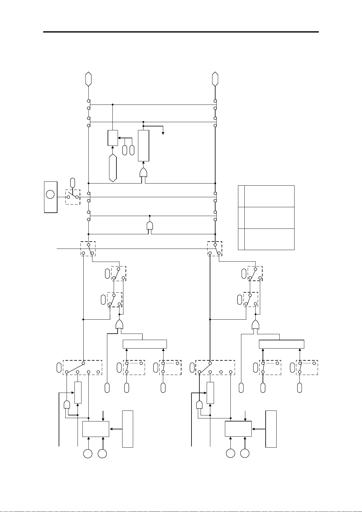
4.3 Drive Command Generator
FWD
Run
Decision
Set Frequency
H96
ON at 1, 3
Priority: STOP Key
(LE)
Enable
Communications Link
Timer
F23
F25
(Timer Operation Time)
Stop Frequency
Start Frequency
#
Forcibly
OFF, if
both are
ON.
REV
Note)
The S codes are communication-related function codes.
Refer to the user's manual of RS-485 communication
for details.
Output
-ONON
-OFFOFF
bit 13 bit 14
OFF ON OFF
OFF OFF OFF
ON - ON
OFF - OFF
ON ON ON
ON OFF OFF
(Outputs the value of the assigned bit)
-:Not assigned
* Truth Table for S06 (bit 13, bit 14) Processor
y99
Data Input
Link Function
for Supporting
0,1
2,3
H30
Link
Communications
0,1
2,3
*
S06 (bit 13, bit 14)
Processor
ON
at 98
F02
Run/Stop
Operation
0
1
2
3
Hold
Hold
Run Command
E98
[FWD]
S06
#
Release
S06
bit 0
Hold
Run Command
bit 13
(Hold Prohibited)
Ready for Jogging
[REV]
ON
at 98
E99
S06
bit 14
Run Command
F02
Run/Stop
Operation
0
1
2
Hold
y99
Data Input
Link Function
for Supporting
0,1
2,3
Link
H30
Communications
0,1
2,3
*
S06 (bit 13, bit 14)
Processor
ON
at 99
E98
[FWD]
3
S06
Run Command
Hold
S06
bit 1
#
Release
bit 13
Run Command
Hold
[REV]
(Hold Prohibited)
Ready for Jogging
ON
at 99
E99
S06
bit 14
Run Command
RUN
(FWD)
(HLD)
STOP
(FWD)
(HLD)
RUN
STOP
Figure 4.2 Drive Command Generator
4-4
Page 73

4.3 Drive Command Generator
The drive command generator shown in Figure 4.2 produces final drive comm ands (FWD: Drive the motor i n
the forward direction) and (REV: Drive the motor in reverse direction) from the r un commands that are given
by various means and modified/switched by function codes.
Additional and supplemental information is given below.
- For the run command given by the
the
key and releases it upon depression of the key except during jogging operation.
/
key, the generator holds the command ON upon depression of
- The hold command HLD holds the run forward/reverse commands FWD/REV until it is turned OFF. This
allows you to run the inverter in "3-Wire Operation." Refer to the function code E01 in Chapter 9
"FUNCTION CODES" for details.
If you do not assign a hold command HLD to any digital input terminals, then the "2-Wire Operation"
using the FWD and REV command will be active.
/
- Setting 0 (zero) for function code F02 allows you to operate the inverter using the
key on the
built-in keypad for the run command, while the FWD and REV commands determine direction of motor
rotation. The logic shown in the block diagram shows you that if the run command from the
key and
either the FWD or REV command are given, then the internal run command <FWD> or <REV> decode d
internally by the logic turns ON.
- S06 (2-byte data for bit 15 through bit 0 can be manipulated), the operation command by the
communications link, includes:
- Bit 0: assigned to FWD
- Bit 1: assigned to REV
- Bits 13 and 14: programmable bits equivalent to the terminal inputs [FWD] and [REV]
- In the block diagram, all of these are noted as operation commands. The data setting for function co d e
E98 to specify the terminal signal property for [FWD] and E99 for [REV] determine which bit value
should be selected as the run command. If bits 13 and 14 hav e th e same setting to specify the property
for (FWD) or (REV), the output of bit 13-14 processor logic will follow the truth table list ed in Fig ure
4.2.
- If either one of bits 13 and 14 is ON (1 as logic value), the OR logic will make the link command LE
turn ON.
- If both run commands FWD and REV come ON concurrently, the logic forces the internal run commands
<FWD> and <REV> to immediately turn OFF.
- If you set 1 or 3 to function code H96 (STOP key priority/Start Check) to make the
key priority
effective, then depressing the key forces the internal run commands <FWD> and <REV> to
immediately turn OFF.
- If you have enabled operat io n via the timer, inputting any run command starts the timer. The internal run
command <FWD> or <REV> and hold command HLD triggered by key pad will be aut om atically turned
OFF after the time preset in the timer has elapsed.
Chap. 4 BLOCK DIAGRAMS FOR CONTROL LOGIC
- If the reference frequency is lower than the start frequency (F23) or the stop frequency (F25), the internal
run commands will remain OFF.
4-5
Page 74

4.4 Terminal Command Decoders
Figures 4.3 (a) through (d) show five types of the terminal command decoder for the digital input signals.
[X1]
E01
Normal/Negative Logic Selection
[X1]
<1000
≧1000
Run Command 1
S06
bit 2
E02
Normal/Negative Logic Selection
[X2]
<1000
≧1000
Run Command 1
S06
bit 3
E03
Normal/Negative Logic Selection
[X3]
<1000
≧1000
Run Command 1
S06
bit 4
E98
Normal/Negative Logic Selection
[FWD]
<1000
≧1000
Run Command 1
S06
bit 13
E99
Normal/Negative Logic Selection
[REV]
<1000
≧1000
Run Command 1
S06
bit 14
Notes)
- Each number shown at switches E01 to E03, E98 and
E99 is data in normal logic system.
- The DCBRK (“Enable DC braking”) cannot be used
for negative logic system.
- The S codes are communication-related function codes.
Refer to the user's manual of RS-485 communication for details.
[X2]
[X3]
[FWD]
[REV]
Communications
Link
H30
0,1
2,3
Communications
Link
H30
0,1
2,3
Communications
Link
H30
0,1
2,3
Communications
Link
H30
0,1
2,3
Communications
Link
H30
0,1
2,3
0,1
2,3
0,1
2,3
0,1
2,3
0,1
2,3
0,1
2,3
Link Function
for Supporting
Data Input
y99
Link Function
for Supporting
Data Input
y99
Link Function
for Supporting
Data Input
y99
Link Function
for Supporting
Data Input
y99
Link Function
for Supporting
Data Input
y99
Communications Link
Figure 4.3 (a) Terminal Command Decoder (General)
Enable
(LE)
E01
E02
E03
E98
E99
[X1]
0
1
2
3
4
11
12
13
20
21
33
34
[X2]
0
1
2
3
4
11
12
13
20
21
33
34
[X3]
0
1
2
3
4
11
12
13
20
21
33
34
[FWD]
0
1
2
3
4
11
12
13
20
21
33
34
[REV]
0
1
2
3
4
11
12
13
20
21
33
34
SS1 (X1)
SS2 (X1)
SS4 (X1)
SS8 (X1)
RT1 (X1)
Hz2/Hz1 (X1)
M2/M1 (X1)
DCBRK (X1)
Hz/PID (X1)
IVS (X1)
PID-RST (X1)
PID-HLD (X1)
SS1 (X2)
SS2 (X2)
SS4 (X2)
SS8 (X2)
RT1 (X2)
Hz2/Hz1 (X2)
M2/M1 (X2)
DCBRK (X2)
Hz/PID (X2)
IVS (X2)
PID-RST (X2)
PID-HLD (X2)
SS1 (X3)
SS2 (X3)
SS4 (X3)
SS8 (X3)
RT1 (X3)
Hz2/Hz1 (X3)
M2/M1 (X3)
DCBRK (X3)
Hz/PID (X3)
IVS (X3)
PID-RST (X3)
PID-HLD (X3)
SS1 (FWD)
SS2 (FWD)
SS4 (FWD)
SS8 (FWD)
RT1 (FWD)
Hz2/Hz1 (FWD)
M2/M1 (FWD)
DCBRK (FWD)
Hz/PID (FWD)
IVS (FWD)
PID-RST (FWD)
PID-HLD (FWD)
SS1 (REV)
SS2 (REV)
SS4 (REV)
SS8 (REV)
RT1 (REV)
Hz2/Hz1 (REV)
M2/M1 (REV)
DCBRK (REV)
Hz/PID (REV)
IVS (REV)
PID-RST (REV)
PID-HLD (REV)
(X1)
(X2)
(X3)
(FWD)
(REV)
The final output
turns ON if one of
signals is ON by
ORing operation,
when E01, E02,
E03, E98, and E99
are set to the same
data.
Select Multistep
Frequency
(SS1)
Select Multistep
Frequency
(SS2)
Select Multistep
Frequency
(SS4)
Select Multistep
Frequency
(SS8)
Select ACC/DEC
Time
(RT1)
Switch Frequency
Command 2/1
(Hz2/Hz1)
Select motor 2/
motor 1
(M2/M1)
Enable DC braking
(DCBRK)
Cancel PID Control
(Hz/PID)
Switch
Normal/Inverse
Operation
(IVS)
Reset PID Integral
and
Differential
Components
(PID-RST)
Hold PID Integral
Component
(PID-HLD)
4-6
Page 75

4.4 Terminal Command Decoders
[X1]
[X1]
[X2]
[X3]
[FWD]
E01
Normal/Negative Logic Selection
<1000
≧1000
[X2]
<1000
<1000
<1000
E02
E03
E98
[X3]
[FWD]
Normal/Negative Logic Selection
≧1000
Normal/Negative Logic Selection
≧1000
Normal/Negative Logic Selection
≧1000
[X1]
E01
[X2]
E02
[X3]
E03
[FWD]
E98
9
24
9
24
9
24
Note)
Each number shown at switches E01 to
Enable External
Alarm Trip
(THR)
Enable
Communications
Link
(LE)
Chap. 4 BLOCK DIAGRAMS FOR CONTROL LOGIC
E03, E98 and E99 is data in normal
logic system.
9
24
E99
[REV]
[REV]
Normal/Negative Logic Selection
<1000
≧1000
[REV]
E99
9
24
Figure 4.3 (b) Terminal Command Decoder (Terminal Signal Inputs)
[FWD]
E98
[FWD]
[REV]
98
99
[REV]
E99
98
99
Run Forward
(FWD)
Run Reverse
(REV)
Figure 4.3 (c) Terminal Command Decoder (Terminal Signal Input Excluding Negative Logic)
4-7
Page 76

Figure 4.3 (d) Terminal Command Decoder (ORing with Link Commands/Ignoring Link Commands)
4-8
Page 77

4.4 Terminal Command Decoders
Programmable digital input terminals [X1], [X2], [X3], [FWD] and [REV] can be assigned to internal
terminal commands such as FWD or REV decoded by data settin gs of related fu nction codes as shown in the
block diagrams in Figures 4.3 (a) through 4.3 (d). In the decoders, negative logic input signals are also
applicable if you set data of 1000s to the function code.
The contents of the block diagram are div ided into five gr oups, dependi ng on whether inputs are assigne d for
the same internal terminal comm ands respectively or t he commands iss ued from the comm unications facility
(linked operation) specify the internal commands. Each of the diagrams shown in Figure 4.3 has following
role.
- Figure 4.3 (a) The terminal command decoder (general) shows the decoding process of the internal
commands functioning with the negative l ogic inputs. T his is switchab le with inputs from
the communications facility (for example, link operation commands received through
RS-485 communications).
- Figure 4.3 (b) The terminal command decoder (terminal signal inputs) shows the process to decode
internal terminal commands de dica ted to the con trol si gnal in put applie d to the in verter 's
terminal block. These commands cannot be changed via the com munications facility (link
operation command).
- Figure 4.3 (c) The terminal command decoder (terminal signal input excluding negative logic) shows
process to produce FWD and REV commands. In this process, settings via the
communications facility do not take effect. In the next process of the drive command
generator, however, they may take effect. (Refer to the block diagram in Section 4.3,
"Drive Command Generator.") To keep the inverter operation safe, any negative logic
input for the FWD and REV commands cannot be applied.
- Figure 4.3 (d) The upper part of the terminal command decoder (ORing with link commands/ignoring
link commands) shows the process to produce commands by ORing signals issued from
the communications facility and the control sign al input term inal bl ock (Logical Orin g. If
any of input signals is ON, then the command becomes ON.).
The lower part of the terminal command decoder shows the control in which only digital
inputs of all control signals are enabled even if link operation command LE has been
turned ON.
Chap. 4 BLOCK DIAGRAMS FOR CONTROL LOGIC
4-9
Page 78

4.5 Digital Output Selector
Frequency
E32
Detection
Output frequency 1 (before
slip compensation)
Frequency Detection
(Detection level)
(Select motor
Electronic
characteristics)
Thermal
Overload
Protection
for Motor 1
detection level)
(Thermal time
Overload Early
Warning/Current
Detection/Low
Current Detection
Current
Detection 2
Thermistor
(Overload
constant)
(Level)
(Timer)
(Level)
(Timer)
(Level)
selection)
[C1]
0
(Mode
1,2
E31
F10
F11
F12
E34
E35
E37
E38
H27
H26
0
(Hysteresis width)
1.0 Hz
OFF
Electronic Thermal
Control for Motor
Electronic Thermal
Control for Motor
Current Detection
Low Current Detection
Current Detection 2
PTC thermistor
activated
Wire Break Detection
ON
Alarm
”
Note) Each number shown at switches E20 to E27 is data in normal logic system.
Figure 4.4 Digital Output Signal Selector
Inverter running (Speed > 0)
Motor overload early warning (OL)
”
Overload prevention control (OLP)
Motor stopped due to
slow flowrate under
Motor overheat detected
Frequency arrival signal (FAR)
Frequency detected (FDT)
Undervoltage detected (LU)
Inverter output limiting (IOL)
Auto-restarting after
momentary power failure
Auto-resetting (TRY)
Service lifetime alarm (LIFE)
Inverter running 2 (RUN2)
Current detected (ID)
Current detected 2 (ID2)
Low current detected (IDL)
Under PID control (PID-CTL)
PID control
Switched to motor 2
by thermistor
Brake signal (BRKS)
Terminal [C1] wire
Frequency
arrival detected
Alarm output (for
any alarm)
break
(RUN)
(IPF)
(PID-STP)
(SWM2)
(THM)
(C1OFF)
(FARFDT)
(ALM)
[Y1] (Transistor output)
E20
0
1
2
3
5
6
7
26
30
35
36
37
38
41
43
44
49
56
57
59
87
99
[30A/B/C] (Status output contact)
0
1
2
3
5
6
7
26
30
35
36
37
38
41
43
44
49
56
57
59
87
99
<1000
≧1000
E27
<1000
≧1000
Transistor Output
[Y1]
Relay Contact Output
[30A/B/C]
4-10
Page 79

4.5 Digital Output Selector
The block diagram shown in Figure 4.4 shows you the processes to select the internal logic signals for
feeding to two digital output signals [Y1] and [30A/B/ C]. The output t erminals [Y1] (a transis tor switch) and
[30A/B/C] (mechanical relay contacts) are programmable. You can assign various functions to these
terminals using function codes E20 and E27. Setting data of 1000s allows you to use these terminals for the
negative logic system.
Chap. 4 BLOCK DIAGRAMS FOR CONTROL LOGIC
4-1 1
Page 80
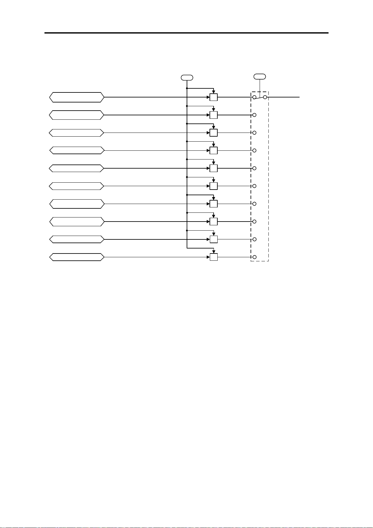
4.6 Analog Output (FMA) Selector
[FMA] (Output Gain) [FMA] (Selector)
F30
F31
Output Frequency 1
(Before Slip Compensation)
Output Frequency 2
(After Slip Compensation)
Output Current
Output Voltage
Input Power
PID Feedback Value
DC Link Bus Voltage
Test Analog Output
PID command (SV)
PID output (MV)
×
×
×
×
×
×
×
×
×
×
Figure 4.5 Analog Output (FMA) Selector
0
1
2
3
6
7
9
14
15
16
Analog Output
[FMA]
The block diagram shown in Figure 4.5 shows the process for selecting and processing the analog signals to
be outputted to the analog output terminal [FMA]. Function code F31 determines the signals to be outputted
to [FMA]. Function code F30 scales the output s ignal to a level sui table for th e m eters to be con nected to the
[FMA] terminal.
The output voltage range is 0 to 10 VDC and the maximum allowable load current is 2 m A. This is capable of
driving two analog voltmeters with a common rating.
The test analog output is full-scale voltage output that adjusts the scale of the connected meter.
4-12
Page 81
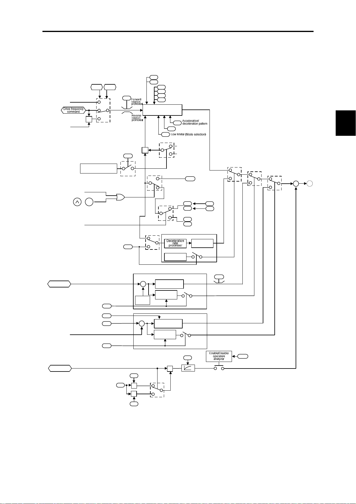
4.7 Drive Command Controller
Figures 4.6 (a) and (b) show the drive command controller.
F03
Maximum frequency 1
Base frequency 1
F04
F23
Starting frequency 1
(Holding time)
F24
F25
Stop frequency
F39
(Holding time)
ACC/DEC processor
H11
H63
H07
Deceleration mode
"-1"
FWD REV
"0"
Rotational
direction
limitation
H08
×
4.7 Drive Command Controller
Chap. 4 BLOCK DIAGRAMS FOR CONTROL LOGIC
Calculated
torque
Output current
Calculated
torque
Automatic deceleration
(Mode selection)
(DC link bus voltage)
> (Limit level)
Ready for jogging
(JOG)
STOP
+
Select ACC/DEC time
(RT1)
Automatic deceleration
(Mode selection)
Restart mode after
momentary power failure
(Frequency fall rate)
Current limiter (Level)
Current limiter
(Mode selection)
Slip compensation gain
for driving
Rated slip frequency
Slip compensation gain
for braking
Figure 4.6 (a) Drive Command Controller and Related Part of the Inverter
Overload
prevention
control
H69
H14
F44
F43
Cancel if
H69≠1
P12
H69
H70
P09
P11
+
+
-
x
(Braking)
x
×
H70=0.00
-
Limit
level
(Driving)
*1
H70≠0.00
"1"
"3"
ACC/DEC Time
(Jogging operation)
Acceleration
time 1
Deceleration
time 1
Overload prevention control
Operation
analyzer
Automatic deceleration
Main control
block
Run
decision
Current limit control
Current limiter
Run
decision
Slip compensation
response time
x
H54
F07
F08
E10
Acceleration time 2
E11
Deceleration time 2
Frequency
processor
Cancel if
H70 = 999
Cancel if
H69 = 0
Cancel if
F43 = 0
P10
H70=999
H70≠999
Acceleration
time
S08
S09
Deceleration
time
Torque limiter
(Braking)
H76
H69=0,1
H69=
2,4
F42
Control mode selection 1
*1 Only the deceleration time should be
three times the specified one.
F43=0
F43≠0
+
1
+
4-13
Page 82
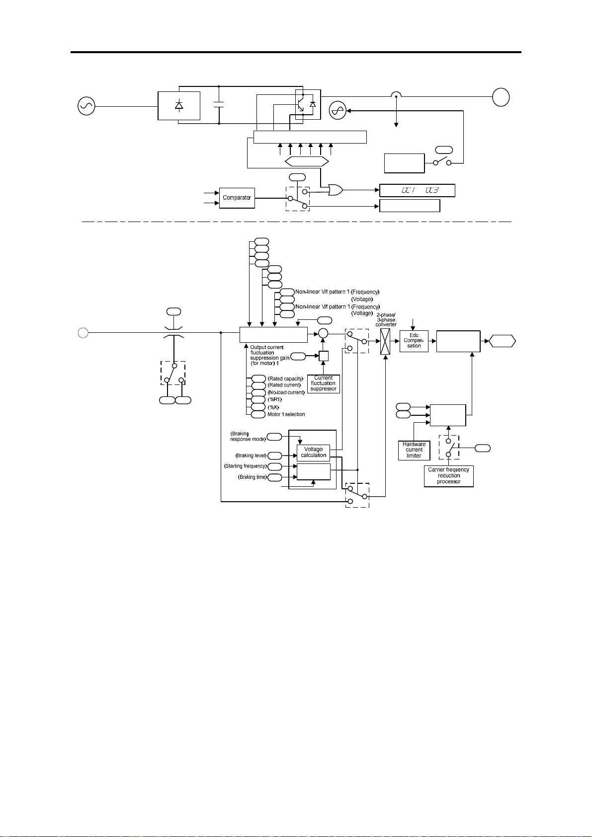
Power
source
1
Rectifier
Output Current
(Iu, Iv, Iw)
Current limit level
Frequency
limiter
(High)
F15
H64≠0.0
H64 F16
Low limiter
(Lower limiting
frequency)
H64=0.0
Frequency
limiter
(Low)
DC link bus
capacitor
Instantaneous overcurrent
limiting (Mode selection)
F03
Maximum frequency 1
Base frequency 1
F04
Rated voltage at base frequency 1
F05
Maximum output voltage 1
F06
F09
F37
F42
Voltage calculator
Motor 1
P02
P03
P06
P07
P08
P99
DC braking 1
H95
DC braking 1
F21
F20
F22
DCBRK
Cooling fan
Gate drive circuit
PWM signals
H12
0
1
Torque boost 1
Load selection/Auto torque boost/Auto saving operation 1
Control mode selection 1
H50
H51
H52
H53
+
H71
Deceleration
characteristics
Output current
(Iu, Iv, Iw)
Cooling fan
ON-OFF
control
Alarm to
Current limit
processing
Edc
(DC link bus
voltage)
-
x
H80
Motor sound
(Carrier frequency)
F26
F27
(Tone)
DC braking
Operation
analyzer
Cooling fan
ON-OFF
control
H06
PWM
processor
Carrier
frequency
M
Motor
PWM
signals
Cancel if H98 = 0
H98
(Bit 0)
Figure 4.6 (b) Drive Command Controller and Related Part of the Inverter
4-14
Page 83

4.7 Drive Command Controller
The simplified block diagram shown in Figure 4.6 explains t he process in which the inverter drives the m otor
according to the internal run command <FWD>/<REV> from the frequency genera tor, or the PID freque ncy
command from the PID controller, and the run commands.
Additional and supplemental information is given below.
- The logic shown in the left part of the block diagram processes the drive frequency command so as to
invert (×(-1)) the command for reverse rotation of the motor or to replace it with 0 (zero) for stopping the
motor.
- The accelerator/decelerator processor determines the output frequency of the inverter by referring to the
set data of related function codes. If the output frequency exceeds the peak frequency given by function
code F15, the controller limits the output frequency at the peak.
- Acceleration/deceleration time is selectable from acceleration/deceleration time 1 or 2, or
acceleration/deceleration time for jogging operation. The suppression of the regenerative braking feature
may multiply the commanded acceleration/deceleration time by 3. Refer to role of function code H69 in
the block diagram.
- If the overload prevention control feature is active, then the logic automatically switches the output
frequency to one of overload suppression control and controls the inverter using the switched frequency.
However, if the current limit control is active (F43 ≠ 30, H12 = 1), the overload prevention control
automatically becomes inactive.
- If the current limit control is active, then the logic automatically switches the output frequency to one of
current limit control and controls inverter using the switched frequency.
- The slip compensation facility adds frequency components based on the preset rated slip frequency (P12)
to the frequency currently commanded. The logic adjusts the error according to the settings of the slip
compensation gain for driving (P09) and braking (P11).
the set data of function code P09 that controls slip compensation gain for the motor.
- The voltage processor determines the output voltage of the inverter. The processor adjusts the output
voltage to control the motor output torque.
- If DC braking control is active, the logic switches the voltage and frequency control components to ones
determined by the DC braking block to feed the proper power to the motor for DC braking.
Chap. 4 BLOCK DIAGRAMS FOR CONTROL LOGIC
4-15
Page 84
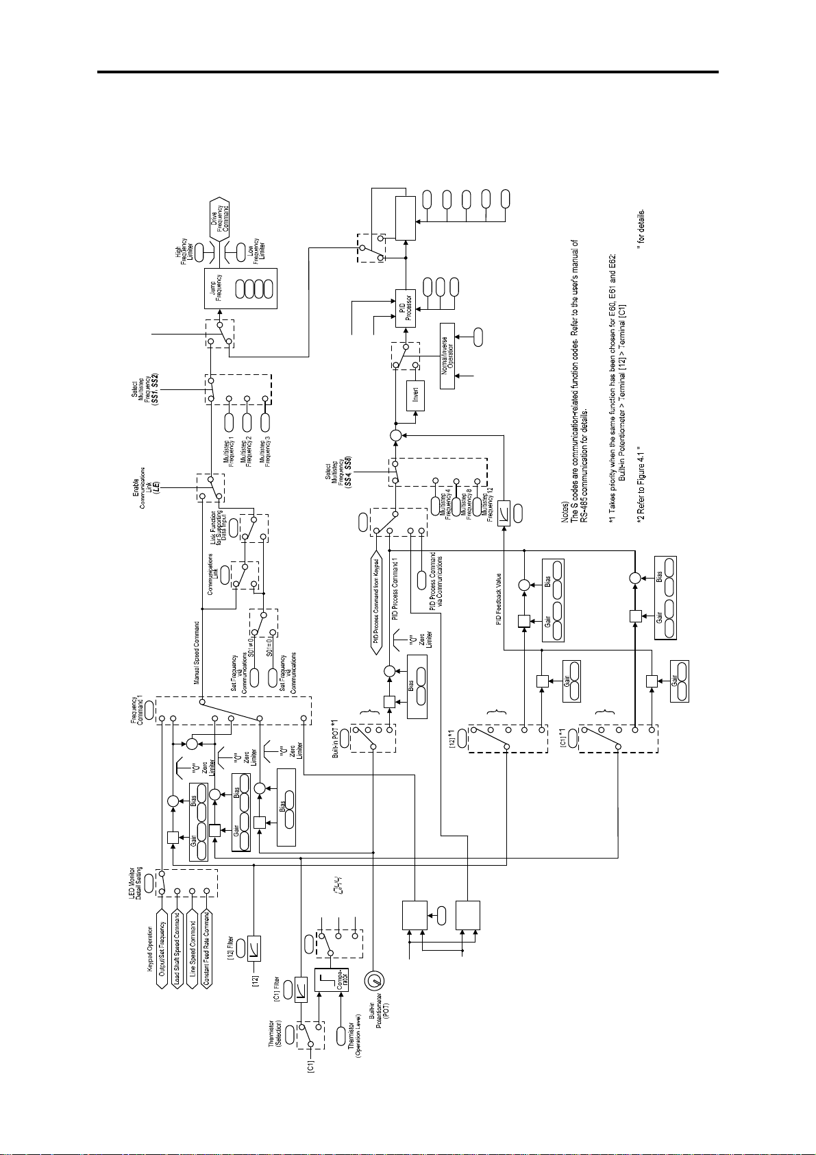
4.8 PID Frequency Command Generator
(Initiation
PID Control
(Operation level for
J15
stop
processing
Slow flowrate
0 Hz
F15
F16
PID Control
P (Gain)
C01
C02
C03
C04
J03
frequency)
slow flowrate stop)
(Elapsed time from
slow flowrate stop)
(Initiation deviation
level for slow
flowrate stop)
(Start latency time
for slow flowrate
stop)
J23
J24
J17
J16
D (Differential
time)
I (Integral time)
J05
J04
(Hz/PID)
Cancel PID Control
(PID-RST)
(PID-HLD)
Reset PID Integral and
Differential Components
Hold PID Integral Component
C05
C06
C07
-
+
C08
y99
0,2
1,3
H30
0,2
1,3
S01
S05
F01
0
1
2
3
4
+
+
7
PID Control
(Remote
E60
J02
command SV)
012
041
*2
3
S13
+
+
C51 C52
×
3
J01
PID Control
(Mode selection)
(IVS)
Switch
Operation
Normal/Inverse
Block Diagram for Drive Frequency Command Generator
C12
C16
J06
PID Control
(Feedback filter)
C52C51
+
+
C34C32
×
C34C32
×
*2
0
E61
3
1
5
2
*2
0
1
2
E62
C52C51
+
+
C39
×
C37
C39
×
C37
3
5
+
+
×
E48
456
0,1,2
+
+
×
C32 C34 F18 C50
+
+
F18 C50
×
C37 C39 F18 C50
UP/DOWN
Control
(Initial frequency
Alarm
Motor overheat
detected by
thermistor
THM
1
2
0
C33
H26
C38
0
1,2
H26
H27
UP/
UP (Increase
DOWN
output frequency)
UP
Control
setting)
UP/
H61
DOWN
Control
DOWN
DOWN (Decrease
output frequency)
Figure 4.7 PID Frequency Command Generator
4-16
Page 85

4.8 PID Frequency Command Generator
The block diagram shown in Figure 4.7 shows the PID frequency command generator that becomes active
when the PID control is enabled (J01= 1 or 2). The logic shown generates the final frequency command
according to the PID process command given by various means of setting and feedback, or frequency settings
as a speed command given manually, and various means of switching.
Additional and supplemental information is given below.
- Switching of data settings for frequency 2 (C30), auxiliary frequencies 1 and 2 (E60 to E62) as manual
speed commands will be disabled.
- For multistep frequency settings, settings 1 to 3 are exclusively applicable to the manual PID speed
command.
- For selecting analog input (terminal [12], [C1], or built-i n POT) as the PID process comm and, you need to
set proper data for function codes E60 to E62 and J02.
- Multistep frequencies that can be used as a PID process command include multistep frequency 4 (C08), 8
(C12) and 12 (C16).
- To switch the operation between normal and inverse, the logic inverses polarity of deviation between the
PID command and its feedback (turning INV command ON/OFF, or setting J01 = 1 or 2).
- Refer to Section 4.2 " Drive Frequency Command Generator" for explanations of common items.
Chap. 4 BLOCK DIAGRAMS FOR CONTROL LOGIC
4-17
Page 86

Page 87

Chapter 5
RUNNING THROUGH RS-485
COMMUNICATIONS
This chapter describes an overview of inverter operation through the RS-485 communications link. Refer to
the RS-485 Communication User's Manual (MEH448) for details.
Contents
5.1 Overview on RS-485 Communication........................................................................................................5-1
5.1.1 Common specifications....................................................................................................................... 5-2
5.1.2 Connector specifications..................................................................................................................... 5-3
5.1.3 Connection..........................................................................................................................................5-4
5.2 Overview of FRENIC Loader.....................................................................................................................5-5
5.2.1 Specifications...................................................................................................................................... 5-5
5.2.2 Connection..........................................................................................................................................5-6
5.2.3 Function overview...............................................................................................................................5-6
5.2.3.1 Setting of function code..............................................................................................................5-6
5.2.3.2 Running status monitor...............................................................................................................5-7
5.2.3.3 Test-running ................................................................................................................................5-9
Page 88

Page 89

5.1 Overview on RS-485 Communication
5.1 Overview on RS-485 Communication
Using the RS-485 communications port on the FRENIC-Mini series enables the following extended
functions.
Operation from a remote keypad
Connecting a remote keypad to the RS-485 communications port on the inverter with an extension
cable allows you to mount the keypad on the easy-to-access front of a panel. The maximum length of
the extension cable is 20 m (66 ft.).
Operation by FRENIC Loader
The FRENIC-Mini can be connected to a Windows-based PC, on whi ch you can run FREN IC Loader
(see Section 5.2 "Overview of FRENIC Loader.") to edit the function code data and monitor the
running status information of the inverter.
Operation from the host equipment
The FRENIC-Mini can be connected to host equipment (m aster) such as a PLC or com puter. It can act
as a slave device.
Protocols for managing a network inclu ding inverters include t he Modbus RTU protocol (compliant to
the protocol established by Modicon Inc.) that is widely used in FA markets and the Fuji
general-purpose protocol that supports the FRENIC-Mini and conventional series of inverters.
Chap. 5 RUNNING THROUGH RS-485 COMMUNICATIONS
For the remote keypad, the inverter uses the dedicated protocol that automatically switches
the operation source to the remote keypad, so no function code setting is required.
For FRENIC loader, however, you need to set up function code H30 for some
communications conditions although the dedic ated protocol is used.
5-1
Page 90

5.1.1 Common specifications
Items Specifications
Protocol FGI-BUS Modbus RTU Loader protocol
Compliance Fuji general-purpose
RS-485 communication
No. of supporting
stations
Max. transmission
cable length
No. of available
station addresses
Synchronization Start-Stop system
Message frame format FGI-BUS Modbus RTU Loader
Frame
synchronization
Transmission m ode Half-duplex
Messaging system Polling/Selecting/Broadcast Command message
Transmission
character format
Character length 8 or 7 bits (selectable by
Parity Even, Odd, or None
Stop bit length 1 or 2 bits
Error checking Sum-check CRC-16 Sum-check
Transmission speed 2400, 4800, 9600, 19200, or 38400 bps 2400 or 4800 bps
Host device: 1
Inverters: Up to 31
500 m (1600 ft.)
1 to 31 1 to 247 1 to 255
Detection of SOH (Start
Of Header) character
ASCII Binary
the function code)
(selectable by the function code)
(selectable by the
function code)
Modicon Modbus
RTU-compliant
Detection of no-data
transmission time for
3-byte period
8 bits (fixed)
When "No parity" is
selected: 2 bits
When Even or Odd
parity is selected: 1 bit
Special commands
dedicated to Loader
(Not disclosed)
Detection of header
character (Start code
96H)
Even
1 bit (fixed)
5-2
Page 91

r
5.1 Overview on RS-485 Communication
5.1.2 Connector specifications
The RS-485 communications port uses an RJ-45 co nnect or whos e pin assignment is listed in the table
below.
Pin Signal name Function Remarks
1 and 8 Vcc Power source for the remote keypad 5V
2 and 7 GND Reference voltage level GND
3 and 6 NC No connection -4 DX- RS-485 communication data (-)
5 DX+ RS-485 com muni cat i o n dat a (+)
Built-in terminating resistor:
112 Ω
Open/close switchable by
SW3
Chap. 5 RUNNING THROUGH RS-485 COMMUNICATIONS
RJ-45 connecto
The RJ-45 connector has power source pins (pins 1 and 8) designed for the remote keypad.
When connecting other devices to the RJ-45 connector, take care not to use those pins.
For the details about the termi nating resistor swit ch, refer to the FRENIC-Min i Instruction
Manual, Section 2.3.7 "Setting up the slide switches."
When connecting a remote keypad, it is no t ne cessary t o turn th e terminating resistor switch
ON.
5-3
Page 92

5.1.3 Connection
You need to select devices suitable for your network configuration, referring to the figure shown
below.
Converter
Some computers are not equipped with an RS-485 communications port but with a USB port, so a
USB/RS-485 converter is required to connect them to the RS-485 communications p ort on the inverter.
It is recommended that insulated converters such as RS-485/RS-485 converters be used for
eliminating electric noise.
Multi-drop branch connector
The RS-485 communications port on the FRENIC-Mini uses an RJ-45 connector. For multi-drop
connection of inverters, therefore, multi-drop branch connectors (MS8-BA-JJJ by SK Koki Co.) are
required.
Cable
For the connection of the remote keypad, use an 8-wire straight cable with an RJ-45 connector.
(Remote keypad extension cable option: CB-5S)
For the connection of other equipment or connection of FRENIC-Mini inverters with each other, us e a
cable that has signal wires only. (EIA568-compliant 10BASE-T)
- No converter is required for connection of the remote keypad.
- To connect the FVR-E11S series of general-purpose inverters to the FRENIC-Mini
series, take necessary measures for the difference of the pin assignment between
FVR-E11S and FRENIC-Mini series to avoid a short-circuited failure.
5-4
Page 93

5.2 Overview of FRENIC Loader
5.2 Overview of FRENIC Loader
FRENIC Loader is a software tool that supports the operation of the inverter via an RS-485
communications link. It allows you to remotely run or stop the inverter, edit, set, or manage the
function codes, monitor key param eters and values during operation, as well as monitoring the runni ng
status (including alarm information) of the inverters on the RS-485 communications network.
For details, refer to the FRENIC Loader Instruction Manual.
5.2.1 Specifications
Item
Name of software FRENIC Loader
Supported inverter FRENIC-MEGA/Multi/Eco/Mini (Note 1)
No. of supported inverters
Recommended cable
CPU Intel Pentium III 600 MHz or later (Note 2)
OS
Memory 512 MB or more RAM 1GB or more recommended
Hard disk 20 MB or more free space
COM port
Operating environment
Monitor resolution 800 x 600 or higher
COM port COM1 to COM255
Transmission rat e USB connection:
Character length 8 bits Prefixed
Stop bit length 1 bit Prefixed
Parity Even Prefixed
No. of retries None, 1 to 10
Transmission requi rements
Timeout setting
(Note 1) • FRENIC Loader cannot be used with inverters that do not support SX protocol (protocol for
handling Loader commands).
• Inverters other than standard series may not display function code data normally.
(Note 2) Use a PC with as high a performance as possible, since some slow PCs may not properly refresh
the operation status monitor and Test-run window s.
(White on black indicates factory default)
When connected to RS-485
communications ports: Up to 31
10BASE-T cable with RJ-45 connectors
compliant with EIA568
Microsoft Wi ndows XP (32-bit )
Microsoft V ista (32-bit)
Microsoft 7 (32-bit, 64-bit)
USB or RS-232C (conversion to RS-485
communication required to connect
inverters)
Between loader and keypad
= fixed at 12 Mbps
Between keypad and inverter
= fixed at 19200 bps
RS-485 connection:
38400, 19200, 9600, 4800, 2400 (bps)
(100 ms, 300 ms, 500 ms), (1.0 to 1.5 to
1.9 s), (2.0 to 9.0 s) or (10.0 to 60.0 s)
Specifications
Remarks
For the RS-485 interface
XGA (1024 x 768), 16-bit
color or higher is
recommended
PC COM ports assigned to
Loader
19200 bps or more is
recommended.
No. of retry times before
detecting communications
error
This setting should be longer
than the response interval
time specified by function
code y09 of the inverter.
Chap. 5 RUNNING THROUGH RS-485 COMMUNICATIONS
5-5
Page 94

5.2.2 Connection
By connecting a number of inverters to one PC, you can control one inverter at a time or a number of
inverters simultaneously. You can also simultaneously monitor a number of inverters on the
multi-monitor.
For instructions on how to connect inverters to a PC, refer to Section 5.1.3 "Connection" in this
manual and the RS-485 Communication User's Manual (MEH448).
5.2.3 Function overview
5.2.3.1 Setting of function code
You can set, edit, and check the setting of the inverter’s function code data.
List and Edit
In List and edit, you can list and edit func tion codes with functio n code No., name, set val ue, set range,
and factory default.
You can also list function codes by any of the following groups according to your needs:
• Function code group
• Function codes that have been modified from their factory defaults
• Result of comparison with the settings of the inverter
• Result of search by function code name
• User-specified function code set
5-6
Page 95

5.2 Overview of FRENIC Loader
Comparison
You can compare the function code da ta currently being edited with tha t saved in a fi le or stored in the
inverter.
To perform a comparison and review the result displayed, click t he Comparison tab and then click the
Compared with inverter tab or click the Compared with file tab, and specify the file name.
The result of the comparison will be displayed also in the Comparison Result column of the list.
File information
Clicking the File information tab displays the property and comments for identifying the function
code editing file.
(1) Property
Shows file name, inverter model, inverter’s capacity, date of readout, etc.
(2) Comments
Displays the comments you have entered. You can write any comments necessary for identifying the
file.
5.2.3.2 Running status monitor
The running status monitor offers five monitor functions: Multi-monitor, I/O m onitor, System monitor,
Alarm monitor, and Meter display. You can choose an appropriate m onitoring form at according to t he
purpose and situation.
Multi-monitor
Allows you to monitor the
status of more than one
inverter in a list format.
Chap. 5 RUNNING THROUGH RS-485 COMMUNICATIONS
I/O monitor
Allows you to monitor the
ON/OFF states of the digital
input signals to the inverter
and the transistor output
signals.
5-7
Page 96
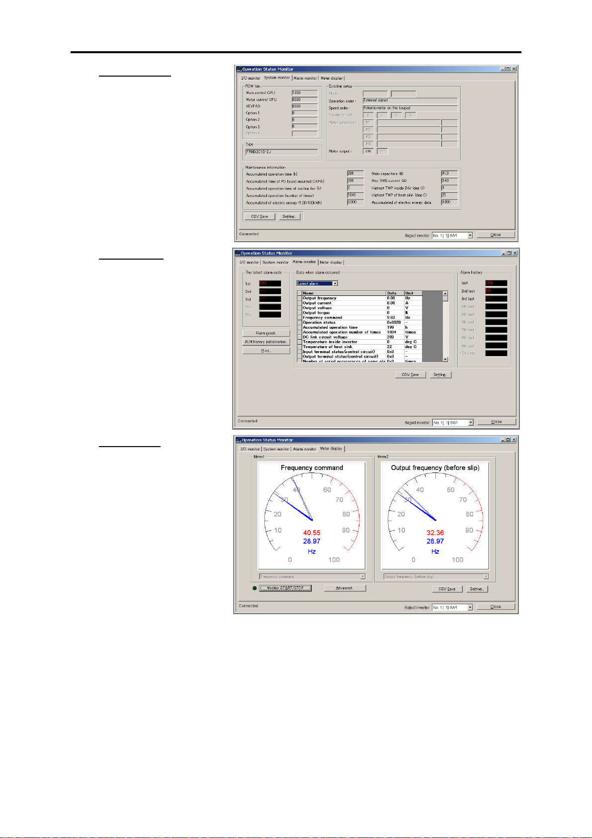
System monitor
Allows you to check the
inverter’s system information
(version, model, maintenance
information, etc.).
Alarm monitor
The alarm monitor shows the
alarm status of the selected
inverter. In this window, you
can check the details of the
alarm that currently occurs
and the related information.
Meter display
Displays analog readouts of
the selected inverter (such as
output frequency) on analog
meters. The example on the
right displays the reference
frequency and the output
frequency.
5-8
Page 97
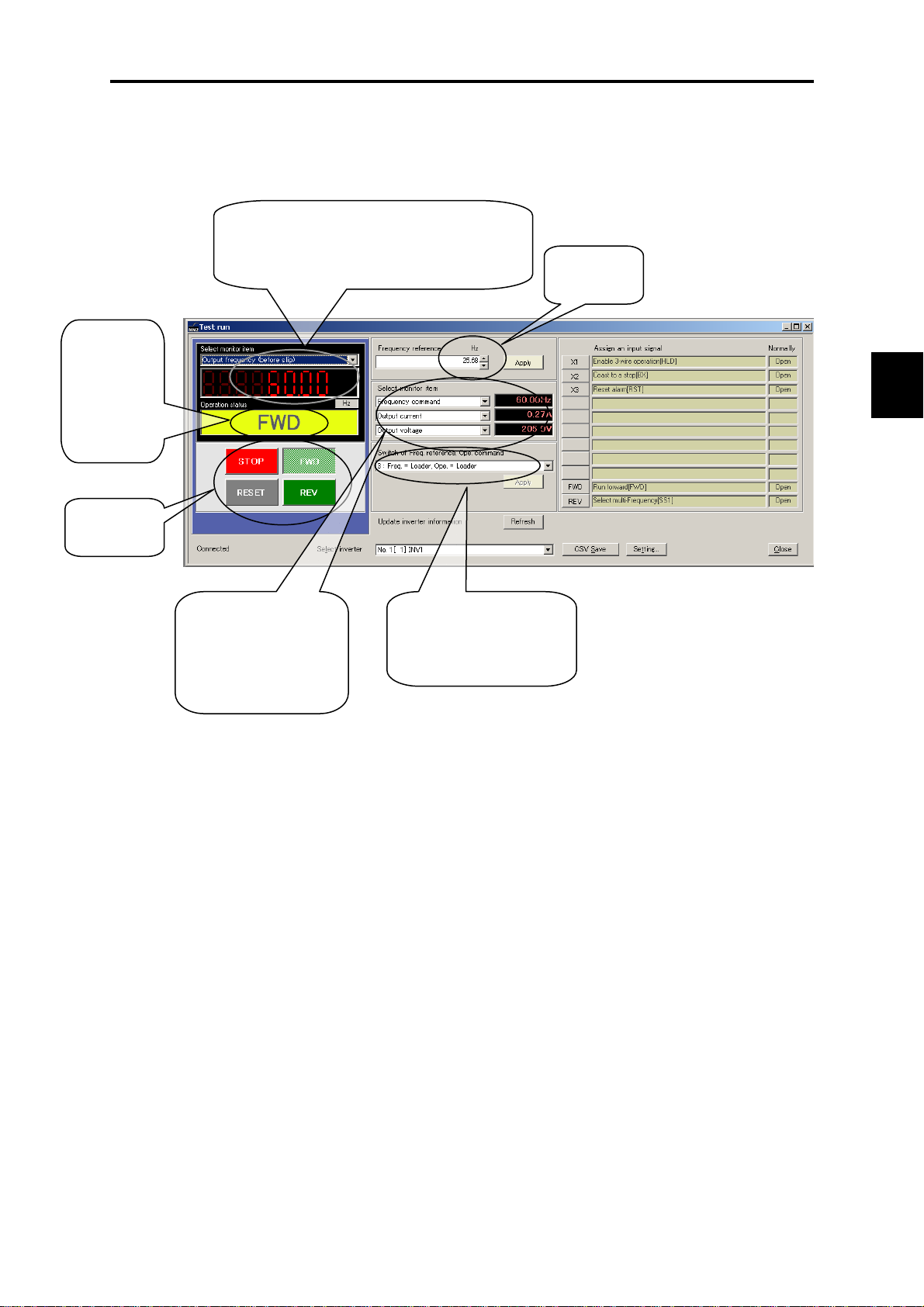
5.2.3.3 Test-running
The test-running feature allows you to test-run the motor in the forward or reverse direction while
monitoring the running status of the selected inverter.
Operationsta
tus
Shows FWD,
REV, STOP
and alarm
codes.
LED monitor
Shows the running status (output frequency,
current, etc.).
5.2 Overview of FRENIC Loader
Reference
frequency
Chap. 5 RUNNING THROUGH RS-485 COMMUNICATIONS
Operation
buttons
Select monitor item
Select the operation
status information to be
monitored in real-time.
Select the frequency and run
command sources and click
Apply.
5-9
Page 98

Page 99

Chapter 6
SELECTING PERIPHERAL EQUIPMENT
This chapter describes how to use a range of peripheral equipment and options, FRENIC-Mini's
configuration with them, and requirements and precautions for selecting wires and crimp terminals.
Contents
6.1 Configuring the FRENIC-Mini...................................................................................................................6-1
6.2 Selecting Wires and Crimp Terminals.........................................................................................................6-2
6.2.1 Recommended wires...........................................................................................................................6-4
6.2.2 Crimp terminals.................................................................................................................................6-12
6.3 Peripheral Equipment................................................................................................................................6-13
[ 1 ] Molded case circuit breaker (MCCB), earth leakage circuit breaker (ELCB) and
magnetic contactor (MC)............................................................................................................. 6-13
[ 2 ] Surge killers.................................................................................................................................6-17
[ 3 ] Arresters ......................................................................................................................................6-18
[ 4 ] Surge absorbers ...........................................................................................................................6-19
6.4 Selecting Options......................................................................................................................................6-20
6.4.1 Peripheral equipment options............................................................................................................6-20
[ 1 ] Braking resistors .......................................................................................................................... 6-20
[ 2 ] DC reactors (DCRs) .................................................................................................................... 6-24
[ 3 ] AC reactors (ACRs) .................................................................................................................... 6-26
[ 4 ] Output circuit filters (OFLs)........................................................................................................ 6-28
[ 5 ] Surge suppression unit (SSU)...................................................................................................... 6-30
[ 6 ] Zero-phase reactors for reducing radio noise (ACLs).................................................................6-31
[ 7 ] Options for 100 V single-phase power supply............................................................................. 6-32
6.4.2 Options for operation and communications......................................................................................6-33
[ 1 ] External potentiometer for frequency setting..............................................................................6-33
[ 2 ] Remote keypad "TP-E1" .............................................................................................................6-34
[ 3 ] USB-equipped remote keypad (TP-E1U).................................................................................... 6-35
[ 4 ] Extension cable for remote operation (CB-S).......................................................................... 6-36
[ 5 ] Inverter support loader software..................................................................................................6-36
6.4.3 Extended installation kit options.......................................................................................................6-37
[ 1 ] Mounting adapters....................................................................................................................... 6-37
[ 2 ] Rail mounting bases .................................................................................................................... 6-38
[ 3 ] NEMA1 kit (NEMA1-C2-).........................................................................................6-39
6.4.4 Meter options....................................................................................................................................6-40
[ 1 ] Frequency meters.........................................................................................................................6-40
Page 100

 Loading...