

Page 1

Compact Inverter
Three-phase 200 V series: FRN0001 to 0020C2S-2
Three-phase 400 V series: FRN0002 to 0011C2S-4
Single-phase 200 V series: FRN0001 to 0012C2S-7
Instruction Manual
Thank you for purchasing our FRENIC-Mini series of inverters.
• This product is designed to drive a three-phase induction motor and three-phase permanent
magnet synchronous motor. Read through this instruction manual and be familiar with the
handling procedure for correct use.
• Improper handling might result in incorrect operation, a short life, or even a failure of this
product as well as the motor.
• Deliver this manual to the end user of this product. Keep this manual in a safe place until this
product is discarded.
• For instructions on how to use an optional device, refer to the instruction and installation
manuals for that optional device.
Fuji Electric Co., Ltd. INR-SI47-1729a-E
Page 2

Copyright © 2013 Fuji Electric Co., Ltd.
All rights reserved.
No part of this publication may be reproduced or copied without prior written permission from Fuji
Electric Co., Ltd.
All products and company names men tioned in this manual are trademarks or registered trademar ks
of their respective holders.
The information contained herein is subject to change without prior notice for improvement.
Page 3

Table of Contents
Preface .............................................................iii
Safety precautions................................................iv
Conformity to the Low Voltage Directive in the EU...ix
Precautions for use...............................................xi
How this manual is organized................................xiv
Chapter 1 BEFORE USING THE INVERTER....1-1
1.1 Acceptance Inspection.............................. 1-1
1.2 External Views...........................................1-2
1.3 Transportation...........................................1-2
1.4 Storage Environment.................................1-3
1.4.1 Temporary storage............................ 1-3
1.4.2 Long-term storage.............................1-3
Chapter 2 MOUNTING AND WIRING OF THE
Chapter 3 OPERATION USING THE KEYPAD. 3-1
INVERTER........................................ 2-1
2.1 Operating Environment ............................. 2-1
2.2 Installing the Inverter.................................2-1
2.3 Wiring........................................................2-2
2.3.1 Removing and mounting the terminal
block covers...................................... 2-2
2.3.2 Terminal ar rang ement and screw
specifications.................................... 2-3
2.3.3 Recommended wire sizes................. 2-4
2.3.4 Wiring precautions............................2-6
2.3.5 Wiring for main circuit terminals and
grounding terminals.......................... 2-7
2.3.6 Wiring for control circuit terminals... 2-11
2.3.7 Setting up the jumper switches....... 2-18
2.3.8 Cautions relating to harmonic
component, noise, and leakage
current.............................................2-20
3.1 Names and Functions of Keypad
Components.............................................. 3-1
3.2 Overview of Operation Modes................... 3-2
3.3 Running mode........................................... 3-4
3.3.1 Monitoring the running status............3-4
3.3.2 Setting up reference frequency and
PID process command......................3-5
3.3.3 Running/stopping the motor.............. 3-7
3.4 Programming mode...................................3-8
3.4.1 Setting up the function codes
– "Data Setting"...............................3-10
3.4.2 Checking changed function codes
– "Data Checking"........................... 3-13
3.4.3 Monitoring the running status
– "Drive Monitoring"........................3-15
3.4.4 Checking I/O signal status
– "I/O Checking"..............................3-19
3.4.5 Reading maintenance information
– "Maintenance Information"........... 3-23
3.4.6 Reading alarm information
– "Alarm Information"...................... 3-26
3.5 Alarm mode............................................. 3-29
Chapter 4 RUNNING THE MOTOR ...................4-1
4.1 Test Run.....................................................4-1
4.1.1 Checking prior to powering on...........4-1
4.1.2 Powering ON and checking...............4-1
4.1.3 Preparation before a test run
--Configuring function code data........4-2
4.1.4 Test run..............................................4-5
4.2 Operation...................................................4-5
4.2.1 Jogging Operation.............................4-6
Chapter 5 FUNCTION CODES..........................5-1
5.1 Function Code Tables................................5-1
5.2 Details of Function Codes........................5-21
5.3 Notes in Driving PMSM............................5-78
Chapter 6 TROUBLESHOOTING......................6-1
6.1 Before Proceeding with Troubleshooting ...6-1
6.2 If No Alarm Code Appears on the LED
Monitor.......................................................6-2
6.2.1 Abnormal motor operation.................6-2
6.2.2 Problems with inverter settings..........6-8
6.3 If an Alarm Code Appears on the LED
Monitor.....................................................6-10
6.4 If an Abnormal Pattern Appears on the
LED Monitor while No Alarm Code is
Displayed.................................................6-24
Chapter 7 MAINTENANCE AND INSPECTION.7-1
7.1 Daily Inspection..........................................7-1
7.2 Periodic Inspection.....................................7-1
7.3 List of Periodical Replacement Parts.........7-3
7.3.1 Judgment on service life....................7-4
7.4 Measurement of Electrical Amounts in
Main Circuit................................................7-6
7.5 Insulation Test............................................7-8
7.6 Inquiries about Product and Guarantee.....7-9
7.6.1 When making an inquiry....................7-9
7.6.2 Product warranty...............................7-9
Chapter 8 SPECIFICATIONS.............................8-1
8.1 Standard Models........................................8-1
8.1.1 Three-phase 200 V class series........8-1
8.1.2 Three-phase 400 V class series........8-2
8.1.3 Single-phase 200 V class series.......8-3
8.2 Common Specifications.............................8-4
8.3 Terminal Specifications ..............................8-7
8.3.1 Terminal functions..............................8-7
8.3.2 Connection diagram in operation
by external signal inputs....................8-7
8.4 External Dimensions..................................8-9
8.4.1 Standard models................................8-9
8.5 Protective Functions ................................8-11
Chapter 9 LIST OF PERIPHERAL
Chapter 10 APPLICATION OF DC
EQUIPMENT AND OPTIONS............9-1
REACTORS (DCRs)........................10-1
i
Page 4

Chapter 11 COMPLIANCE WITH STANDARDS..11-1
11.1 Compliance with European Standards .....11-1
11.2 Compliance with EMC Standards.............11-2
11.2.1 General............................................11-2
11.2.2 Recommended installation
procedure.........................................11-2
11.2.3 Leakage current of EMC-complaint
filter (optional)..................................11-4
11.3 Harmonic Component Regulation in the
EU 11-5
11.3.1 General comments...........................11-5
11.3.2 Compliance with the harmonic
component regulation......................11-6
11.4 Compliance with the Low Voltage
Directive in the EU....................................11-6
11.4.1 General............................................11-6
11.4.2 Points for consideration when using
the FRENIC-Mini series in a system
to be certified by the Low Voltage
Directive in the EU...........................11-6
ii
Page 5

Preface
Thank you for purchasing our FRENIC-Mini series of inverters.
This product is designed to drive a three-phase in duction motor and three-phase permanent magnet
synchronous motor (PMSM). Read through this instruction manual and be familiar with proper handling and operation of this product.
Improper handling might result in incorrect operation, a short life, or even a failure of this product as
well as the motor.
Have this manual delivered to the end user of this product. Keep this manual in a safe pla ce until this
product is discarded.
Listed below are the other materials related to the use of the FRENIC-Mini. Read them in conjunction
with this manual as necessary.
• FRENIC-Mini User's Manual (24A7-E-0023)
• RS-485 Communication User's Manual (MEH448)
• Catalog (24A1-E-0011)
The materials are subject to change without notice. Be sure to obtain the latest editions for use.
Japanese Guideline for Suppressing Harmonics in Home Electric and General-purpose Appliances
Fuji three-phase 200 V class series of inv erters with a capacity of 3.7 (4.0) kW or less, single-phase
200 V class series with 2.2 kW or less, and single-phase 100 V class series with 0.75 kW or less
were once subject to the "Japanese Guideline for Suppressing Harmonics in Home Electric and
General-purpose Appliances" (established in September 1994 and revised in October 1999), published by the Ministry of International Trade and Industry (currently the Ministry of Economy, Trade
and Industry (METI)).
Since the revision of the guideline in January 2004, however, these inverters have no longer been
subject to the guideline. The individual inverter manu factur ers hav e v olunt arily employ ed harmoni cs
suppression measures.
As our measure, it is recommended that DC reactors (DCRs) authorized in this manual be connected to the FRENIC-Mini series of inverters.
When using DCRs not authorized in this manual, however, consult your Fuji Electric representative
for the detailed specifications.
Japanese Guideline for Suppressing Harmonics by Customers Receiving
High Voltage or Special High Voltage
Refer to the FRENIC-Mini User's Manual (24A7-E-0023), Appendix C for details on this guideline.
iii
Page 6
Safety precautions
Read this manual thoroughly before proceeding with installation, connections (wiring), operation, or
maintenance and inspection. Ensure you have sound knowledge of the device and familiarize
yourself with all safety information and precautions before proceeding to operate the inverter.
Safety precautions are classified into the following two categories in this manual.
Failure to heed the information indicated by this symbol may
lead to dangerous conditions, possibly resulting in death or
serious bodily injuries.
Failure to heed the information indicated by this symbol may
lead to dangerous conditions, possibly resulting in minor or
light bodily injuries and/or substantial property damage.
Failure to heed the information contained under the CAUTION title can also result in serious consequences. These safety precautions are of utmost importance and must be observed at all times.
Application
• FRENIC-Mini is designed to drive a three-phase induction motor and three-phase permanent magnet synchronous motor (PMSM). Do not use it for single-pha se motors or for
other purposes.
Fire or an accident could occur.
• FRENIC-Mini may not be used for a life-support system or other purposes directly related
to the human safety.
• Though FRENIC-Mini is manufactured under strict quality control, install safety devices for
applications where serious accidents or material losses are foreseen in relation to the
failure of it.
An accident could occur.
Installation
• Install the inverter on a nonflammable material such as metal.
Otherwise fire could occur.
• Do not place flammable matter nearby.
Doing so could cause fire.
iv
Page 7
• Do not support the inverter by its terminal block cover during transportation.
Doing so could cause a drop of the inverter and injuries.
• Prevent lint, paper fibers, sawdust, dust, metallic chips, or other foreign materials from
getting into the inverter or from accumulating on the heat sink.
Otherwise, a fire or an accident might result.
• Do not install or operate an inverter that is damaged or lacking parts.
Doing so could cause fire, an accident or injuries.
• Do not get on a shipping box.
• Do not stack shipping boxes higher than the indicated information printed on those box es.
Doing so could cause injuries.
Wiring
• When wiring the inverter to the power source, insert a recommended molded case circuit
breaker (MCCB) or residual-current-operated protective device (RCD)/earth leakage
circuit breaker (ELCB) (with overcurrent protection) in the path of power lines. Use the
devices within the recommended current range.
• Use wires in the specified size.
• When wiring the inverter to the power supply of 500 kVA or more, be sure to connect an
optional DC reactor (DCR).
Otherwise, fire could occur.
• Do not use one multicore cable in order to connect several inverters with motors.
• Do not connect a surge killer to the inverter's output (secondary) circuit.
Doing so could cause fire.
• Be sure to connect the grounding wires without fail.
Otherwise, electric shock or fire could occur.
• Qualified electricians should carry out wiring.
• Be sure to perform wiring after turning the power off.
• Ground the inverter in compliance with the national or local electric code.
Otherwise, electric shock could occur.
• Be sure to perform wiring after installing the inverter body.
Otherwise, electric shock or injuries could occur.
• Ensure that the number of input phases and the rated voltage of the product match the
number of phases and the voltage of the AC power supply to which the product is to be
connected.
Otherwise fire or an accident could occur.
• Do not connect the power source wires to output terminals (U, V, and W).
• Do not insert a braking resistor between terminals P (+) and N (-), P1 and N (-), P (+) and
P1, DB and N (-), or P1 and DB.
Doing so could cause fire or an accident.
v
Page 8
• Generally, control signal wires are not reinforced insulation. If they accidentally touch any
of live parts in the main circuit, their insulation coat may break for any reasons. In such a
case, an extremely high voltage may be applied to the signal lines. Make a complete
remedy to protect the signal line from contacting any hot high voltage lines.
Doing so could cause an accident or electric shock.
• Wire the three-phase motor to terminals U, V, and W of the inverter, aligning phases each
other.
Otherwise injuries could occur.
• The inverter, motor and wiring generate electric noise. Take care of malfunction of the
nearby sensors and devices. To prevent the motor from malfunctioning, implement noise
control measures.
Otherwise an accident could occur.
Operation
• Be sure to install the terminal block cover before turning the pow er on . Do not r emov e the
cover while power is applied.
Otherwise electric shock could occur.
• Do not operate switches with wet hands.
Doing so could cause electric shock.
• If the retry function has been selected, the inverter may automatically restar t and drive the
motor depending on the cause of tripping.
(Design the machinery or equipment so that human safety is ensured after restarting.)
• If the stall prevention function (current limiter), automatic deceleration, and overload
prevention control have been selected, the inverter may operate at an acceleration/deceleration time or frequency diff erent from the set o nes. Design the machine so that
safety is ensured even in such cases.
Otherwise an accident could occur.
• The STOP key is only effective when function setting (Function code F02) has been established to enable the STOP key. Prepare an emergency stop switch separately. If you
disable the STOP key priority function and enable operation by external commands, you
cannot emergency-stop the inverter using the STOP key on the built-in keypad.
• If an alarm reset is made with the operation signal turned on, a sudden start will occur.
Ensure that the operation signal is turned off in advance.
Otherwise an accident could occur.
vi
Page 9
• If you enable the "restart mode after momentary power failure" (Function code F14 = 4 or
5), then the inverter automatically rest arts running the motor w hen the power is recovered.
(Design the machinery or equipment so that human safety is ensured after restarting.)
• If you set the function codes wrongly or without completely understanding this instruction
manual and the FRENIC-Mini User's Manual, the motor may rotate with a torque or at a
speed not permitted for the machine.
An accident or injuries could occur.
• Do not touch the inverter terminals while the power is applied to the inverter even if the
inverter stops.
Doing so could cause electric shock.
• Do not turn the main circuit power on or off in order to start or stop inverter operation.
Doing so could cause failure.
• Do not touch the heat sink or braking resistor because they become very hot.
Doing so could cause burns.
• Setting the inverter to high speeds is easy. Before changing the frequency (speed) se tting,
check the specifications of the motor and machinery.
• The brake function of the inverter does not provide mechanical holding means.
Injuries could occur.
Maintenance and inspection, and parts replacement
• Turn the power off and wait for at least five minutes before starting inspection. Further,
check that the LED monitor is unlit, and check the DC link bus voltage between the P (+)
and N (-) terminals to be lower than 25 VDC.
Otherwise, electric shock could occur.
• Maintenance, inspection, and parts replacement should be made only by qualified persons.
• Take off the watch, rings and other metallic matter before starting work.
• Use insulated tools.
Otherwise, electric shock or injuries could occur.
vii
Page 10

Disposal
• Handle the inverter as an industrial waste when disposing of it.
Otherwise injuries could occur.
Others
• Never attempt to modify the inverter.
Doing so could cause electric shock or injuries.
GENERAL PRECAUTIONS
Drawings in this manual may be illustrated without covers or safety shields for explanation of
detail parts. Restore the covers and shields in the original state and observe the description in
the manual before starting operation.
viii
Page 11

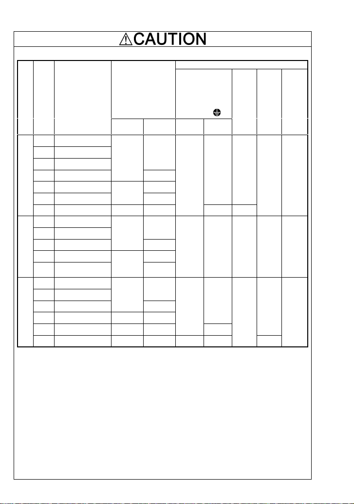
Conformity to the Low Voltage Directive in the EU
If installed according to the guidelines given below, inverters marked with CE are considered as
compliant with the Low Voltage Directive 2006/95/EC.
1. The ground terminal G should always be connected to the ground. Do not use only a
residual-current-operated protective device (RCD)/earth leakage circuit breaker (ELCB)* as
the sole method of electric shock protection. Be sure to use ground wires whose size is
greater than power supply lines.
* With overcurrent protection.
2. When used with the inverter, a molded case circuit breaker (MCCB), residual-current-operated protective device (RCD)/earth leakage circuit breaker (ELCB) or
magnetic contactor (MC) should conform to the EN or IEC standards.
3. When you use a residual-current-operated protective device (RCD)/earth leakage circuit
breaker (ELCB) for protection from electric shock in direct or indirect contact power lines or
nodes, be sure to install type B of RCD/ELCB on the input (primary) of the inverter if the
power source is three-phase 200/400 V. For single-phase 200 V power supplies, use type
A.
When you use no RCD/ELCB, take any other protective measure that isolates the electric
equipment from other equipment on the same power supply line using double or reinforced
insulation or that isolates the power supply lines connected to the electric equipment using
an isolation transformer.
4. The inverter should be used in an environment that does not exceed Pollution Degree 2
requirements. If the environment conforms to Pollution Degree 3 or 4, install the inverter in
an enclosure of IP54 or higher.
5. Install the inverter, AC or DC reactor, input or output filter in an enclosure with minimum
degree of protection of IP2X (Top surface of enclosure shall be minimum IP4X when it can
be easily accessed), to prevent human body from touching directly to live parts of these
equipment.
6. To make an inverter with no integrated EMC filter conform to the EMC directive, it is necessary to connect an external EMC filter to the inv erter and install them p roperl y so that the
entire equipment including the inverter conforms to the EMC directive.
7. Do not connect any copper wire directly to grounding terminals. Use crimp terminals with tin
or equivalent plating to connect them.
8. To connect the three-phase or single-phase 200 V class series of inverters to the power
supply in Overvoltage Category III or to connect the three-phase 400 V class series of inverters to the power supply in Overvoltage Category II or III, a supplementary insulation is
required for the control circuitry.
9. When using inverters at an altitude of more than 2000 m, note that the basic insulation
applies to the insulation degree of the control circuitry. At an altitude of more than 3000 m,
inverters cannot be used.
10. The power supply mains neutral ha s to be earthed for the three-phase 400 V class inverter .
11. The inverter has been tested with IEC61800-5-1 2007 5.2.3.6.3 Short-circuit Current Test
under the following conditions.
Short-circuit current in the supply: 10 kA
Maximum 240 V
Maximum 480 V
ix
Page 12
Conformity to the Low Voltage Directive in the EU (Continued)
12. Use wires listed in IEC60364-5-52.
of
w/o DCR
*1
*3
6
10
20
6
10
20
6
10
Applicable
motor
rating
Power supply voltage
0.1 FRN0001C2S-2□
0.2 FRN0002C2S-2□
0.4 FRN0004C2S-2□
0.75 FRN0006C2S-2□
1.5 FRN0010C2S-2□ 16
2.2 FRN0012C2S-2□
Three-phase 200 V
3.7 FRN0020C2S-2□ 20 35
0.4 FRN0002C2S-4□
0.75 FRN0004C2S-4□
1.5 FRN0005C2S-4□
2.2 FRN0007C2S-4□ 16
3.7
Three-phase 400 V
(4.0)*
0.1 FRN0001C2S-7□
0.2 FRN0002C2S-7□
0.4 FRN0004C2S-7□
0.75 FRN0006C2S-7□ 10 16
1.5 FRN0010C2S-7□ 16 20
Single-phase 200 V
2.2 FRN0012C2S-7□ 20 35 4 6
(kW)
FRN0011C2S-4□
Inverter type
Rated current (A)
MCCB or RCD/ELCB
w/ DCR
6
10
6
10
6
Recommended wire size (mm2 )
Main circuit
power input
[L1/R, L2/S, L3/T]
[L1/L, L2/N]
Grounding [
w/ DCR*3w/o DCR
2.5
2.5 2.5 2.5 2.5 0.5
2.5
G]
2.5 2.5
4 4
2.5
4
*2
*2
Inverter
output
[U, V,
W]
2.5
*2
DCR
Control
[P1,
circuit
P (+)]
(30A,
Braking
resistor
30B,
30C)
[P (+),
DB]
2.5 0.5
2.5
0.5
4
MCCB: Molded case circuit breaker
RCD: Residual-current-operated protective device
ELCB: Earth leakage circuit breaker
Note: A box () in the above table replaces A, C, E, or U depending on the shipping destination. For
three-phase 200 V class series of inverters, it replaces A or U.
* 4.0 kW for the EU. The inverter type is FRN0011C2S-4E.
*1 The frame size and model of the MCCB or RCD/ELCB (with overcurrent prote ction) will vary,
depending on the power transformer capacity. Refer to the related technical documentation fo r
details.
*2 The recommended wire size for main circuits is for the 70°C 600V PVC wires us ed at an ambi ent
temperature of 40°C.
*3 In the case of no DC reactor, the wire sizes are determined on the basis of the effective input
current calculated under the condition that the power supply capacity and impedance are 500 kVA
and 5%, respectively.
x
Page 13

Precautions for use
Driving a 400 V
general-purpose
motor
Torque characteristics and
temperature rise
In running
generalpurpose
motors
Vibration
Noise
High-speed motors
Explosion-proof
motors
In running
special motors
Submersible motors and pumps
Brake motors
When driving a 400 V general-purpose motor with an inv erter
using extremely long wires, damage to the insulation of the
motor may occur. Use an output circuit filter (OFL) if necessary after checking with the motor manufacturer. Fuji motors
do not require the use of output circuit filters because of their
good insulation.
When the inverter is used to run a general-purpose motor, the
temperature of the motor becomes higher than when it is
operated using a commercial power supply. In the low-speed
range, the cooling effect will be weakened, so decrease the
output torque of the motor. If constant torque is required in
the low-speed range, use a Fuji inverter motor or a motor
equipped with an externally powered ventilating fan.
When an inverter-driven motor is mounted to a machine,
resonance may be caused by the natural frequencies of the
machine system.
Note that operation of a 2-pole motor at 60 Hz or higher may
cause abnormal vibration.
* The use of a rubber coupling or vibration dampe ning rubber
is recommended.
* Use the inverter's jump frequency control feature to skip
the resonance frequency zone(s).
When an inverter is used with a general-purpose motor, the
motor noise level is higher than that with a commercial power
supply. To reduce noise, raise carrier frequency of the inverter. Operation at 60 Hz or higher can also result in higher
noise level.
If the reference frequency is set to 120 Hz or more to drive a
high-speed motor, test-run the combination of the inverter
and motor beforehand to check for safe operation.
When driving an explosion-proof motor with an inv erter , use a
combination of a motor and an inverter that has been approved in advance.
These motors have a larger rated current than general-purpose motors. Select an inverter whose rated output
current is greater than that of the motor.
These motors differ from general-purpose motors in thermal
characteristics. Set a low value in the thermal time constant
of the motor when setting the electronic thermal function.
For motors equipped with parallel-connected brakes, their
braking power must be supplied from the input (primary)
circuit. If the brake power is connected to the inverter's output
(secondary) circuit by mistake, the brake will not work.
Do not use inverters for driving motors equipped with series-connected brakes.
xi
Page 14

In running
special
motors
Environmental
conditions
Combination with
peripheral
devices
Geared motors
Synchronous motors
Single-phase
motors
Installation location
Installing an
MCCB or
RCD/ELCB
Installing an MC
in the secondary
circuit
Installing an MC
in the primary
circuit
Protecting the
motor
If the power transmission mechanism uses an oil-lubricated
gearbox or speed changer/reducer, then continuous motor
operation at low speed may cause poor lubrication. Avoid
such operation.
It is necessary to take special measures suitable for this
motor type.
Section 5.3 "Notes in Driving PMSM."
Single-phase motors are not suitable for inverter-driven
variable speed operation. Use three-phase motors.
* Even if a single-phase power supply is available, use a
The heat sink and braking resistor of the inverter may become hot under certain operating conditions, so install the
For details about the PMSM drive, refer to Chapter 5,
three-phase motor as the inverter provides three-phase
output.
inverter on nonflammable material such as metal.
Ensure that the installation location meets the environmental
conditions specified in Chapter 2, Section 2.1 "Operating
Environment."
Install a recommended molded case circuit breaker (MCCB)
or residual-current-operated protective device (RCD)/earth
leakage circuit breaker (ELCB) (with overcurrent protection)
in the input (primary) circuit of the inverter to protect the
wiring. Do not use the circuit breaker capacity exceeding the
recommended rated current.
If a magnetic contactor (MC) is mounted in the inverter's
secondary circuit for switching the motor to commercial
power or for any other purpose, ensure that both the inverter
and the motor are completely stopped before you turn the MC
on or off.
Do not connect a magnet contactor united with a surge killer
to the inverter's secondary circuit.
Do not turn the magnetic conta ctor (MC) in the in put (primary)
circuit on or off more than once an hour as an inverter failure
may result.
If frequent starts or stops are required during motor operation, use FWD/REV signals or the
/ keys.
The electronic thermal function of the inv erter can prote ct the
motor. The operation level and the motor type (general-purpose motor, inverter motor) should be set. For
high-speed motors or water-cooled motors, set a small value
for the thermal time constant and protect the motor.
If you connect the motor thermal relay to the motor with a
long wire, a high-frequency current may flow into the wiring
stray capacitance. This may cause the relay to trip at a current lower than the set value for the thermal relay. If this
happens, lower the carrier frequency or use the output circuit
filter (OFL).
xii
Page 15

Combination with
peripheral
devices
Wiring
Selecting
inverter
capacity
Transportation and
storage
Discontinuance
of power-factor
correcting capacitor
Discontinuance
of surge killer
Reducing noise
Measures against
surge currents
Do not mount power-factor correcting capacitors in the inverter’s primary circuit. (Use the DC reactor to improve the
inverter power factor.) Do not use power-factor correcting
capacitors in the inverter output circuit. An overcurrent trip
will occur, disabling motor operation.
Do not connect a surge killer to the inverter's secondary
circuit.
Use of a filter and shielded wires is typically recommend ed to
satisfy EMC directives.
If an overvoltage trip occurs while the inverter is stopped or
operated under a light load, it is assumed that the surge
current is generated by open/close of the phase-advancing
capacitor in the power system.
* Connect a DC reactor to the inverter.
Megger test
When checking the insulation resist ance of the inverter, use a
500 V Megger and follow the instructions contained in
Chapter 7, Section 7.5 "Insulation Test."
Control circuit
wiring length
Wiring length
between inverter
and motor
Wiring size
Wiring type
When using remote control, limit the wiring length between
the inverter and operator box to 20 m or le ss and u se tw isted
pair or shielded cable.
If long wiring is used between the inverter and the motor, the
inverter will overheat or trip as a result of overcurrent
(high-frequency current flowing into the stray capacitance) in
the wires connected to the phases. Ensure that the wiring is
shorter than 50 m. If this length must be exceeded, lower the
carrier frequency or mount an output circuit filter (OFL).
Select wires with a sufficient capacity by referring to the
current value or recommended wire size.
Do not use one multicore cable in order to connect several
inverters with motors.
Grounding Securely ground the inverter using the grounding terminal.
Select an inverter according to the nominal applied motor
Driving general-purpose
motor
Driving special
motors
When exporting an inverter built in a panel or equipmen t, pack them in a previously
fumigated wooden crate. Do not fumigate them after packing since some parts
inside the inverter may be corroded by halogen compounds such as methyl bro-
listed in the standard specifications table for the inverter.
When high starting torque is required or quick accelera tion or
deceleration is required, select an inverter with a capacity
one size greater than the standard.
Select an inverter that meets the following condition:
Inverter rated current > Motor rated current
mide used in fumigation.
When packing an inverter alone for export, use a laminated veneer lumber (LVL).
For other transportation and storage instructions, see Chapter 1, Section 1.3
"Transportation" and Section 1.4 "Storage Environment."
xiii
Page 16

How this manual is organized
This manual is made up of chapters 1 through 11.
Chapter 1 BEFORE USING THE INVERTER
This chapter describes acceptance inspection and precautions for transportation and storage of the
inverter.
Chapter 2 MOUNTING AND WIRING OF THE INVERTER
This chapter provides operating environment, precautions for installing the inverter, wiring instructions for the motor and inverter.
Chapter 3 OPERATION USING THE KEYPAD
This chapter describes inverter operation using the keypad. The inverter features three operation
modes (Running, Programming and Alarm modes) which enable you to run and stop the motor,
monitor running status, set function cod e data, display runn ing information required for maintenance,
and display alarm data.
Chapter 4 OPERATION
This chapter describes preparation to be made before running the motor for a test and practical
operation.
Chapter 5 FUNCTION CODES
This chapter provides a list of the function code s. Function code s to be used o ften and irregular ones
are described individually.
Chapter 6 TROUBLESHOOTING
This chapter describes troubleshooting procedures to be followed w hen the inv erter malfun ctions or
detects an alarm condition. In this chapter, first check whether any alarm code is displayed or not,
and then proceed to the troubleshooting items.
Chapter 7 MAINTENANCE AND INSPECTION
This chapter describes inspection, measurement and insulation test which are required for safe
inverter operation. It also provides information about periodical replacement parts and guarantee of
the product.
Chapter 8 SPECIFICATIONS
This chapter lists specifications including output ratings, control system, external dimensions and
protective functions.
Chapter 9 LIST OF PERIPHERAL EQUIPMENT AND OPTIONS
This chapter describes main peripheral equipment and options which can be connected to the
FRENIC-Mini series of inverters.
Chapter 10 APPLICATION OF DC REACTOR (DCRs)
This chapter describes a DC reactor that suppresses input harmonic component current.
Chapter 11 COMPLIANCE WITH STANDARDS
This chapter describes standards with which the FRENIC-Mini series of inverters comply.
xiv
Page 17

r
Icons
The following icons are used throughout this manual.
This icon indicates information which, if not heeded , can re sult in the inv erter not opera ting
to full efficiency, as well as information concerning incorrect operations and settings which
can result in acciden ts.
This icon indicates information that can prove handy when performing certain settings o
operations.
This icon indicates a reference to more detailed information.
xv
Page 18
Chapter 1 BEFORE USING THE INVERTER
1.1 Acceptance Inspection
Unpack the package and check that:
(1) An inverter and instruction manual (this manual) are contained in the package.
(2) The inverter has not been damaged during transportation—there should be no dents or parts
missing.
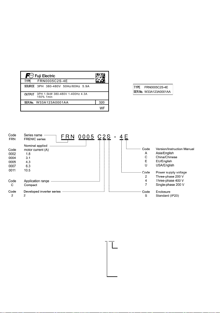
(3) The inverter is the model you ordered. You can check the model name and specifications on the
main nameplate. (Main and sub nameplates are attached to the inverter and are located as
shown on the next page.)
(a) Main Nameplate (b) Sub Nameplate
Figure 1.1 Nameplates
TYPE: Type of inverter
SOURCE: Number of input phases (three-phase: 3PH, single-phase: 1PH), input voltage, input
frequency, input current
OUTPUT: Number of output phases, rated output capacity, rated output voltage, output
frequency range, rated output current, and overload capacity
SER. No.: Product number Manufacturing date
W 3 3 A 1 2 3 A 0 0 0 1 A A 3
2 0
Production week
This indicates the week number that is
numbered from 1st week of January.
The 1st week of January is indicated as
'01'.
Production year: Last digit of year
If you suspect the product is not working properly or if you have any questions about your product,
contact your Fuji Electric representative.
1-1
Page 19
r
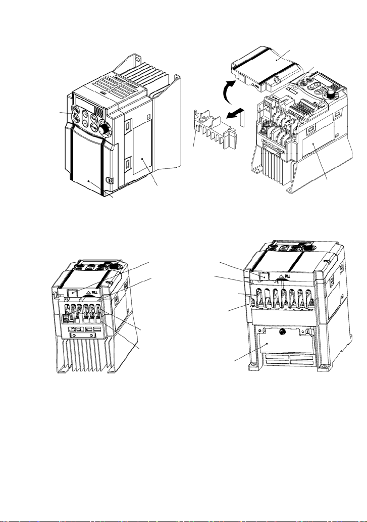
1.2 External Views
(1) External views
Keypad
Control circuit
Main circuit
terminal block
cover
terminal block cove
Sub nameplate
Control circuit terminal bock cover
Main nameplate
Main nameplate
Figure 1.2 External Views of FRENIC-Mini
(2) Wiring section
Barrier for the RS-485
communications port*
Control signal cable
port
DB, P1, P (+) and N (-) wire port
L1/R, L2/S, L3/T, U, V, W,
grounding wire port
L1/R, L2/S, L3/T, P1, P (+), N (-)
wire port
DB, U, V, W,
grounding wire port
(a) FRN0006C2S-2 (b) FRN0010C2S-2
(* When connecting the RS-485 communications cable, remove the control circuit terminal block cover and
cut off the barrier provided in it using nippers.)
Note: A box () in the above model names replaces A, C, E, or U depending on the shipping destination.
For three-phase 200 V class series of inverters, it replaces A or U.
Cooling
fan
Figure 1.3 Wiring Section
1.3 Transportation
• When carrying the inverter, always support its bottom at the front and rear sides with both hands.
Do not hold covers or individual parts only. You may drop the inverter or break it.
• Avoid applying excessively strong force to the terminal block covers as they are made of plastic
and are easily broken.
1-2
Page 20

1.4 Storage Environment
1.4.1 Temporary storage
Store the inverter in an environment that sa tisfies the requirements listed in Table 1.1.
Table 1.1 Environmental Requirements for Storage and Transportation
Item Requirements
Storage
temperature
Relative
humidity
Atmosphere The inverter must not be exposed to dust, direct sunlight, corrosive or flamma ble
pressure
1
*
Assuming a comparatively short storage period (e.g., during transportation or the like).
2
*
Even if the humidity is within the specified requireme nts, avoid such places where the inverter will be
subjected to sudden changes in temperature that will cause condensation to form.
Precautions for temporary storage
(1) Do not leave the inverter directly on the floor.
(2) If the environment does not satisfy the specified requirements listed in Table 1.1, wrap the
inverter in an airtight vinyl sheet or the like for storage.
(3) If the inverter is to be stored in an environment with a high level of humidity, put a drying agent
(such as silica gel) in the airtight package described in item (2).
-25 to +70°C
1
*
5 to 95% *2
gases, oil mist, vapor, water drops or vibration. The atmosphere can contain only a
low level of salt. (0.01 mg/cm
86 to 106 kPa (in storage) Atmospheric
70 to 106 kPa (during transportation)
2
or less per year)
Locations where the inverter is not
subject to abrupt changes in
temperature that would result in the
formation of condensation or ice.
1.4.2 Long-term storage
The long-term storage methods for the inverter vary largely according to the environment of the
storage site. General storage methods are described below.
(1) The storage site must satisfy the requirements specified for temporary storage.
However, for storage exceeding three months, the ambient temperature should be within the
range from -10 to +30°C. This is to prevent the electrolytic capacitors in the inverter from
deteriorating.
(2) The inverter must be stored in a package that is airtight to protect it from moisture. Include a
drying agent inside the package to maintain the relative humidity inside the package to within
70%.
(3) If the inverter has been inst alled in the equipment or control bo ard at a constructi on site where it
may be subjected to humidity, dust or dirt, then remove the inverter and store it in a suitable
environment specified in Table 1.1.
Precautions for storage over 1 year
If the inverter will not be powered on for a long time, the property of the electrolytic capacitors may
deteriorate. Power the inverters on once a year and keep them on for 30 to 60 minutes. Do not
connect the inverters to motors or run the motor.
1-3
Page 21
f
Chapter 2 MOUNTING AND WIRING OF THE INVERTER
2.1 Operating Environment
Install the inverter in an environment that satisfies the requirements listed in Table 2.1.
Table 2.1 Environmental Requirements
Item Specifications
Site location Indoors
Ambient
temperature
Relative
humidity
Atmosphere
Altitude 1,000 m max. (Note 3)
Atmospheric
pressure
Vibration
-10 to +50°C (IP20) (Note 1)
5 to 95% (No condensation)
The inverter must not be exposed to dust,
direct sunlight, corrosive gases, flammable
gas, oil mist, vapor or water drops.
The atmosphere can contain only a low level
of salt.
(0.01 mg/cm
The inverter must not be subjected to sudden
changes in temperature that will cause
condensation to form.
86 to 106 kPa
3 mm (Max. amplitude) 2 to less than 9 Hz
9.8 m/s2 9 to less than 20 Hz
2 m/s2 20 to less than 55 Hz
1 m/s
2
or less per year)
2
55 to less than 200 Hz
(Note 2)
2.2 Installing the Inverter
(1) Mounting base
The temperature of the heat sink may rise up to
approx. 90°C during operation of the inverter, so
the inverter should be mounted on a ba se made o
material that can withstand temperatures of this
level.
Install the inverter on a base made of met al or
other non-flammable material.
A fire may result with other material.
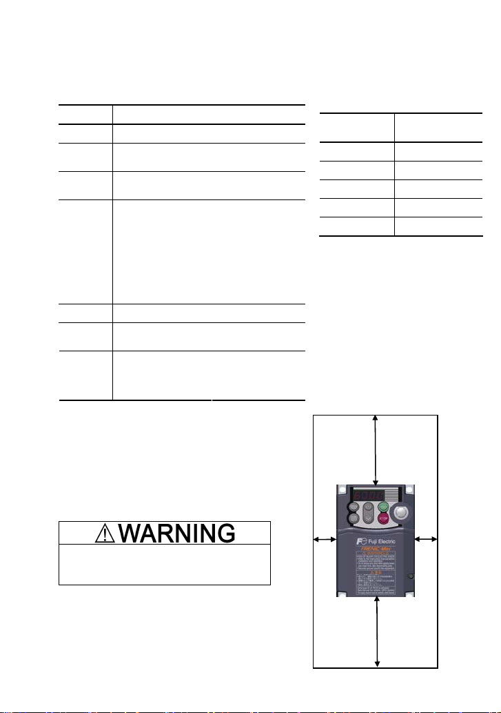
(2) Clearances
Ensure that the minimum clearances indicated in
Figure 2.1 are maintained at all times. When
installing the inverter in the panel of your system,
take extra care with ventilation in side the panel as
the temperature around the inverter tends to
increase.
2-1
Table 2.2 Output Current Derating Factor in
Relation to Altitude
Altitude
1000 m or lower 1.00
1000 to 1500 m 0.97
1500 to 2000 m 0.95
2000 to 2500 m 0.91
2500 to 3000 m 0.88
(Note 1) When inverters are mounted
side-by-side without any gap between them,
the ambient temperature should be within
the range from -10 to +40°C.
(Note 2) Do not install the inverter in an
environment where it may be exposed to
cotton waste or moist dust or dirt which will
clog the heat sink in the inverter. If the
inverter is to be used in such an environment, install it in the panel of your system or
other dustproof containers.
(Note 3) If you use the inverter in an altitude
above 1000 m, you should apply an output
current derating factor as listed in Table 2.2.
Top 100 mm
Left
10 mm
Bottom 100 mm
Figure 2.1 Mounting Direction and
Required Clearances
Output current
derating factor
Right
10 mm
Page 22
When mounting two or more inverters
When mounting two or more inverters in the same unit or panel, basically lay them out side by side.
As long as the ambient temperature is 40°C or lower, inverters can be mounted side by side without
any clearance between them. When mounting the inverters necessarily, one above the other, be
sure to separate them with a partition plate or the like so that any heat radiating from an inverter will
not affect the one(s) above.
(3) Mounting direction
Secure the inverter to the mo unting bas e with four screws or bolt s (M4) so tha t the FRENIC-Mini logo
faces outwards. Tighten those screws or bolts perpendicular to the mounting base.
Do not mount the inverter upside down or horizontally. Doing so will reduce the heat
dissipation efficiency of the inverter and cause the overheat protection function to operate,
so the inverter will not run.
Prevent lint, paper fibers, sawdust, dust, metallic chips, or other foreign materials from getting
into the inverter or from accumulating on the heat sink.
This may result in a fire or accident.
2.3 Wiring
Follow the procedure below. (In the following description, the inverter has already been installed.)
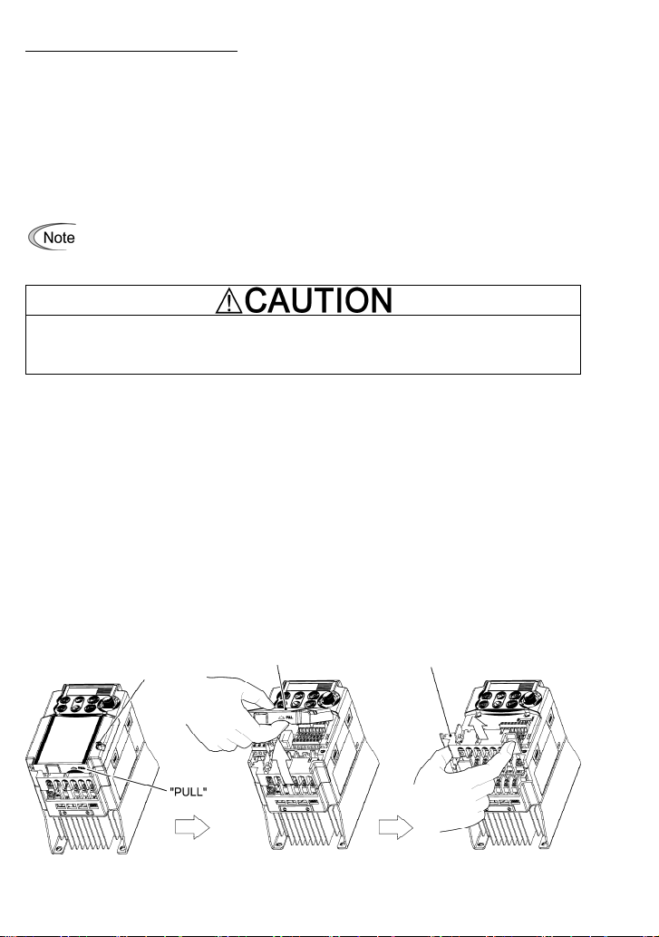
2.3.1 Removing and mounting the terminal block covers
(1) Loosen the screw securing the control circuit terminal block cover.
(2) Insert your finger in the cutout (near "PULL") in the bottom of the control circuit terminal block
cover, then pull the cover towards y ou.
(3) Hold both sides of the main circuit terminal block cover between thumb and forefinge r and slide
it towards you.
(4) After performing wiring, mount the main circuit terminal block cover and control circuit terminal
block cover in the reverse order of removal.
Control circuit terminal
block cover screw
Control circuit terminal
block cover
Main circuit terminal block cover
Figure 2.2 Removing the Terminal Block Covers
2-2
Page 23
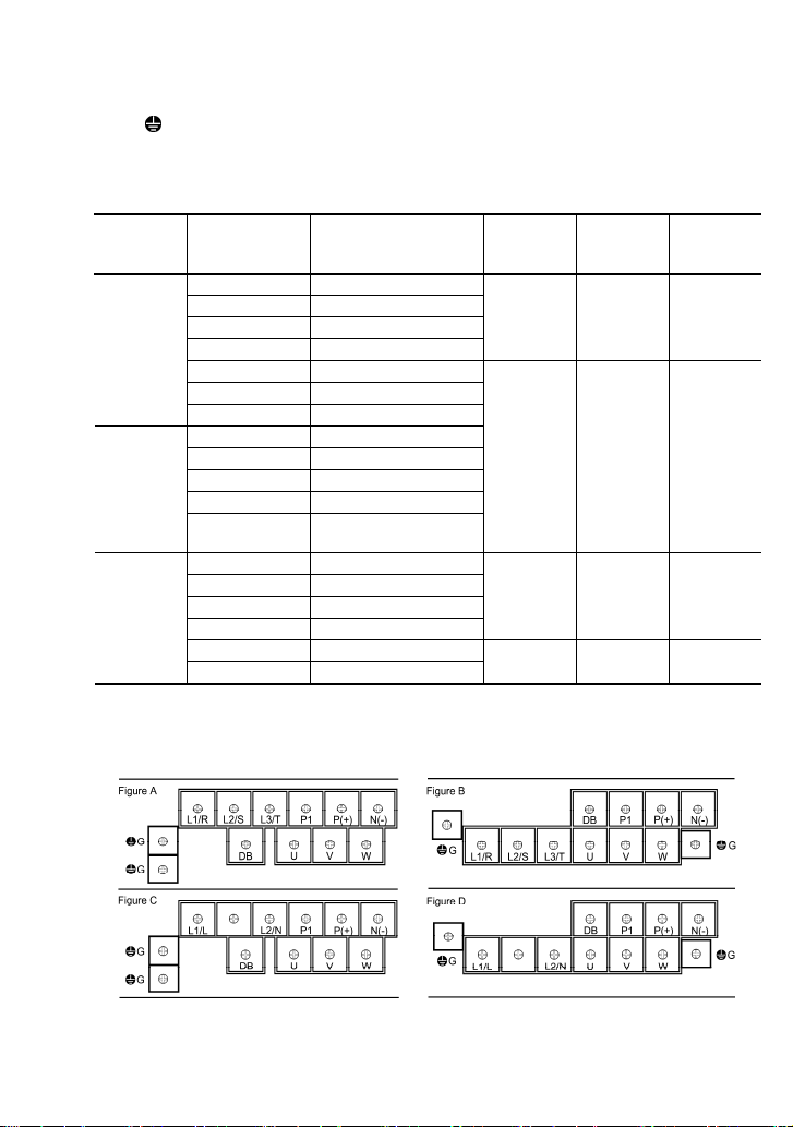
2.3.2 Terminal arrangement and screw specifications
The figures below show the arrangement of the main and control circuit terminals which differs
according to inverter type. The two terminals prepared for grounding, which are indicated by the
symbol
G in Figures A to D, make no distinction between the power supply side (primary circuit)
and the motor side (secondary circuit).
(1) Arrangement of the main circuit terminals
Table 2.3 Main Circuit Terminals
Power
supply
voltage
Nominal ap-
plied motor
(kW)
Inverter type
Terminal
screw size
Tightening
torque
(N·m)
Refer to:
0.1 FRN0001C2S-2
Three-
phase
200 V
0.2 FRN0002C2S-2
0.4 FRN0004C2S-2
0.75 FRN0006C2S-2
1.5 FRN0010C2S-2
M3.5 1.2 Figure A
2.2 FRN0012C2S-2
3.7 FRN0020C2S-2
0.4 FRN0002C2S-4
Three-
phase
400 V
0.75 FRN0004C2S-4
1.5 FRN0005C2S-4
2.2 FRN0007C2S-4
3.7
(4.0)*
FRN0011C2S-4
M4 1.8 Figure B
0.1 FRN0001C2S-7
Single-
phase
200 V
Note: A box () in the above table replaces A, C, E, or U depending on the shipping destination. For
three-phase 200 V class series of inverters, it replaces A or U.
0.2 FRN0002C2S-7
0.4 FRN0004C2S-7
0.75 FRN0006C2S-7
1.5 FRN0010C2S-7
2.2 FRN0012C2S-7
M3.5 1.2 Figure C
M4 1.8 Figure D
* 4.0 kW for the EU. The inverter type is FRN0011C2S-4E.
2-3
Page 24
(2) Arrangement of the control circuit terminals (common to all FRENIC-Mini models)
30A 30B 30C
Screw size: M 2.5 Tightening torque : 0. 4 N•m
Y111Y1E FMA C1 PLC
12 13 11 CM
Screw size: M 2 Tightening torque: 0.2 N•m
X1 X2 X3
CM FWD REV
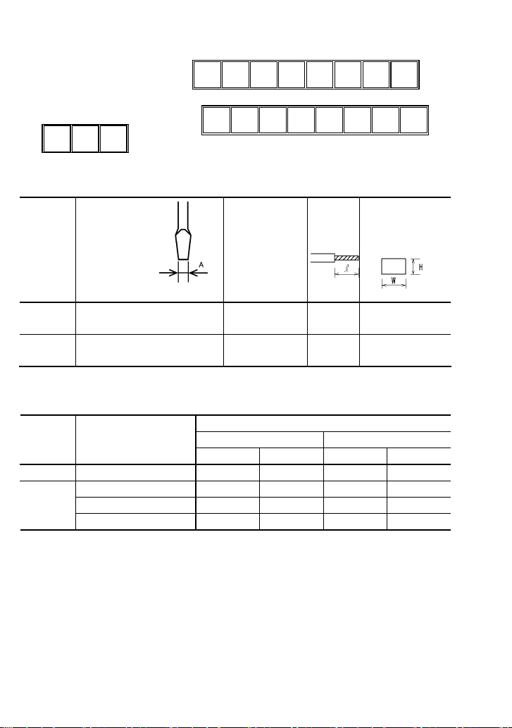
Table 2.4 Control Circuit Terminals
Terminal
symbol
Screwdriver
(Shape of tip,
B x A)
Allowable wire size
Bared wire
length
Thickness of tip: B
[30A], [30B],
[30C]
Other than
the above
* Manufacturer of ferrule terminals: WAGO Company of Japan, Ltd. Refer to Table 2.5.
Flat screwdriver
(0.6 x 3.5 mm)
Flat screwdriver
(0.5 x 2.4 mm)
AWG22 to AWG18
(0.34 to 0.75 mm
AWG24 to AWG18
(0.25 to 0.75 mm
6 to 7 mm 2.8 (W) x 1.7 (H) mm
2
)
5 to 6 mm 1.7 (W) x 1.4 (H) mm
2
)
Ferrule terminal*
Opening dimension in
the terminal block
Table 2.5 Recommended Ferrule Terminals
Type (216-)
Screw size Wire size
With insulated collar Without insulated collar
Short type Long type Short type Long type
M2 AWG24 (0.25 mm2 ) 321 301 151 131
AWG22 (0.34 mm2 ) 322 302 152 132
M2 or M2.5
The length of bared wires to be inserted into ferrule terminals is 5.0 mm or 8.0 mm for the short or long type,
respectively.
AWG20 (0.50 mm2 ) 221 201 121 101
2
AWG18 (0.75 mm
) 222 202 122 102
The following crimping tool is recommended: Variocrimp 4 (Part No. 206-204).
2.3.3 Recommended wire sizes
Table 2.6 lists the recommended wire sizes. The recommended wire sizes for the main circuit
terminals for an ambient temperature of 50°C are indicated for tw o ty pes of w ire: H IV si ngle w ire (for
the maximum allowable temperature 75°C) (before a slash (/)) and IV single wire (for 60°C) (after a
slash (/)),
2-4
Page 25
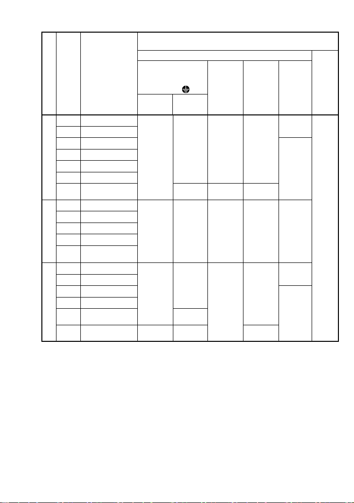
Table 2.6 Recommended Wire Sizes
*1
2
DCR
)
Braking
resistor
[P (+), DB]
Control
circuit
Power supply voltage
Nomi-
nal
applied
motor
(kW)
Inverter type
Main circuit power input
[L1/R, L2/S, L3/T]
[L1/L, L2/N]
Grounding [
Recommended wire size (mm
Main circuit
Inverter
output
G]
[U, V, W]
[P1, P (+)]
w/ DCR*2w/o DCR
FRN0001C2S-2
0.1
FRN0002C2S-2
0.2
FRN0004C2S-2
0.4
FRN0006C2S-2
0.75
FRN0010C2S-2
1.5
FRN0012C2S-2
2.2
Three-phase 200 V
3.7
FRN0020C2S-2
Three-phase 400 V
Single-phase 200 V
Note: A box () in the above table replaces A, C, E, or U depending on the shipping destination. For
three-phase 200 V class series of inverters, it replaces A or U.
0.4
0.75
1.5
2.2
3.7
(4.0)*
0.1
0.2
0.4
0.75
1.5
2.2
FRN0002C2S-4
FRN0004C2S-4
FRN0005C2S-4
FRN0007C2S-4
FRN0011C2S-4
FRN0001C2S-7
FRN0002C2S-7
FRN0004C2S-7
FRN0006C2S-7
FRN0010C2S-7
FRN0012C2S-7
2.0 / 2.0
(2.5)
2.0 / 2.0
(2.5)
2.0 / 2.0
(2.5)
2.0 / 3.5
(4.0)
2.0 / 2.0
(2.5)
2.0 / 5.5
(2.5)
2.0 / 2.0
(2.5)
2.0 / 2.0
(2.5)
2.0 / 3.5
(4.0)
3.5 / 5.5
(6.0)
2.0 / 2.0
(2.5)
2.0 / 3.5
(2.5)
2.0 / 2.0
(2.5)
2.0 / 2.0
(2.5)
2.0 / 2.0
(2.5)
2.0 / 3.5
(2.5)
2.0 / 2.0
(2.5)
2.0 / 2.0
(2.5)
2.0 / 3.5
(4.0)
–
2.0 / 2.0
(2.5)
2.0 / 2.0
(2.5)
–
2.0 / 2.0
(2.5)
DCR: DC reactor
0.5
* 4.0 kW for the EU. The inverter type is FRN0011C2S-4E.
*1 Use crimp terminals covered with an insul ated sheath or insulating tube . Recommended wire sizes a re
for HIV/IV (PVC in the EU).
*2 Wire sizes are calculated on the b asis of input RMS current u nder the condition that the power supply
capacity and impedance are 500 kVA and 5%, respectively.
*3 Insert the DC reactor (DCR) in either of the primary power input lin es. Refer to Chapter 10 for more
details.
2-5
Page 26

2.3.4 Wiring precautions
Follow the rules below when performing wiring for the inverter.
(1) Make sure that the source voltage is within the rated voltage range specified o n the nameplate .
(2) Be sure to connect the power wires to the main circuit power input terminals L1/R, L2/S and
L3/T (for three-phase voltage input) or L1/L and L2/N (for single-phase voltage input) of the
inverter. If the power wires are connected to other terminals, the inv erter w ill b e damag ed w hen
the power is turned on.
(3) Always connect the grounding terminal to prevent electric shock, fire or other disasters and to
reduce electric noise.
(4) Use crimp terminals covered with insulated sleeves for the main circui t terminal wiring to ensure
a reliable connection.
(5) Keep the power supply wiring (primary circuit) and motor wiring (secondary circuit) of the main
circuit, and control circuit wiring as far away as possible from each other.
• When wiring the inverter to the power source, insert a recommended molded case circuit
breaker (MCCB) or residual-current-operated protective device (RCD)/earth leakage
circuit breaker (ELCB) (with overcurrent protection) in the path of power lines. Use the
devices within the related current range.
• Use wires in the specified size.
Otherwise, fire could occur.
• Do not use one multicore cable in order to connect several inverters with motors.
• Do not connect a surge killer to the inverter's output (secondary) circuit.
Doing so could cause fire.
• Be sure to connect the grounding wires without fail.
Otherwise, electric shock or fire could occur.
• Qualified electricians should carry out wiring.
• Be sure to perform wiring after turning the power off.
• Ground the inverter in compliance with the national or local electric code.
Otherwise, electric shock could occur.
• Be sure to perform wiring after installing the inverter body.
Otherwise, electric shock or injuries could occur.
• Ensure that the number of input phases and the rated voltage of the product match the
number of phases and the voltage of the AC power supply to which the product is to be
connected.
Otherwise, fire or an accident could occur.
• Do not connect the power source wires to output terminals (U, V, and W).
• Do not connect a braking resistor to between terminals P (+) and N (-), P1 and N (-), P (+)
and P1, DB and N (-), or P1 and DB.
Doing so could cause fire or an accident.
2-6
Page 27
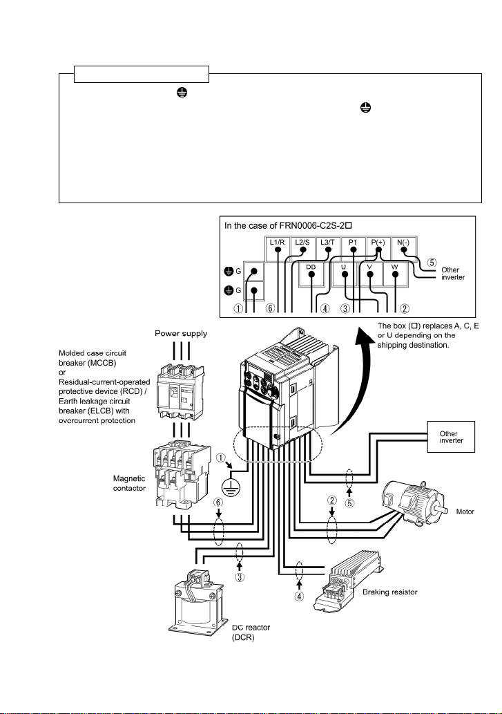
2.3.5 Wiring for main circuit terminals and grounding terminals
Follow the procedure below. Figure 2.3 illustrates the wiring procedure with peripheral equipment.
Wiring procedure
c Grounding terminal G*
1
d Inverter output terminals (U, V, and W) and grounding terminal G*
e DC reactor connection terminals (P1 and P(+))*
f Braking resistor connection terminals (P(+) and DB)*
g DC link bus terminals (P(+) and N(-))*
2
2
2
1
h Main circuit power input terminals (L1/R, L2/S and L3/T) or (L1/L and L2/N)
1
Use either one of these two grounding terminals on the main circuit terminal block.
*
2
*
Perform wiring as necessary.
CAUTION: The above is
an illustration. Do not
connect more than 2 wires
to terminal P (+).
CAUTION: When wiring the inverter to the
power supply of 500 kVA or more, be sure
to connect an optional DC reactor (DCR).
Figure 2.3 Wiring Procedure for Peripheral Equipment
2-7
Page 28
The wiring procedure for the FRN0006C2S-2 is given below as an example. For other inverter
types, perform wiring in accordance with their individual terminal arrangement. (Refer to page 2-3.)
c Grounding terminal ( G)
Be sure to ground either of the two grounding terminals for safety and noise reduction. It is stipulated
by the Electric Facility Technical Standard that all metal frames of electrical equipment must be
grounded to avoid electric shock, fire and other disasters.
Grounding terminals should be grounded as follows:
1) Ground the inverter in compliance with the national or local electric code.
2) Connect a thick grounding wire with a large surface area. Keep the wiring length as short as
possible.
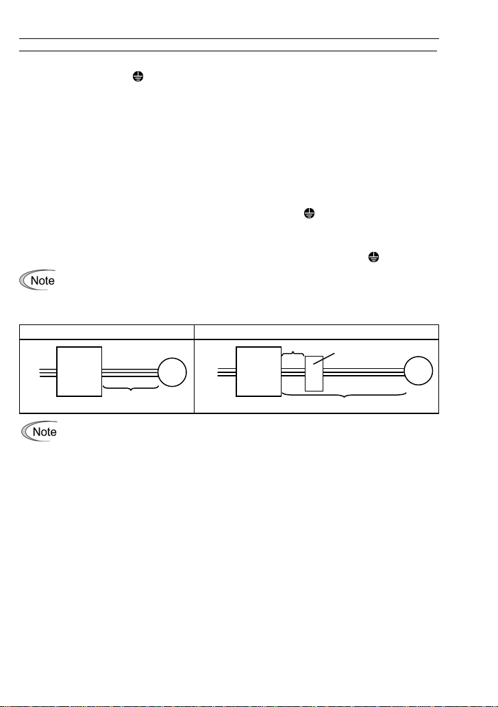
d Inverter output termi nals, U, V, W and grounding terminal ( G)
1) Connect the three wires of the three-phase motor to terminals U, V, and W, aligning phases each
other.
2) Connect the grounding wire of terminals U, V, and W to the grounding terminal (
- The wiring length between the inverter and motor should not exceed 50 m. If it exceeds
50 m, it is recommended that an output circuit filter (option) be inserted.
- Do not use one multicore cable to connect several inverters with motors.
No output circuit filter inserted Output circuit filter inserted
Power
supply
Inverter
Motor
Power
supply
Inverter
5 m or less
Output circuit filter
G).
Motor
50 m or less
• Do not connect a phase-advancing capacitor or surge absorber to the inverter’s output
lines (secondary circuit).
400 m or less
• If the wiring length is long, the stray capacitance between the wires will increase,
resulting in an outflow of the lea kage current. It w ill activ ate the ov ercurrent prote ction,
increase the leakage current, or will not assure the accuracy of the current display. In
the worst case, the inverter could be damaged.
• If more than one motor is to be connected to a single i nv erter, the wiring length should
be the total length of the wires to the motors.
2-8
Page 29
Driving 400 V series motor
• If a thermal relay is installed in the path between the inverter and the motor to protect
the motor from overheating, the thermal relay may malfunction even with a wiring
length shorter than 50 m. In this situation, add an output circuit filter (option) or lower
the carrier frequency (Function code F26: Motor sound (Carrier frequency)).
• If the motor is driven by a PWM-type inverter, surge voltage that is generated by
switching the inverter component may be superimposed on the output voltage and
may be applied to the motor terminals. Particularly if the w iring length is long, the su rge
voltage may deteriorate the insulation resistance of the motor. Consider any of the
following measures.
- Use a motor with insulation that withstands the surge voltage. (All Fuji standard
motors feature insulation that withstands the surge voltage.)
- Connect an output circuit filter (option) to the output terminals (secon dary cir cuits) of
the inverter.
- Minimize the wiring length between the inverter and motor (10 to 20 m or less).
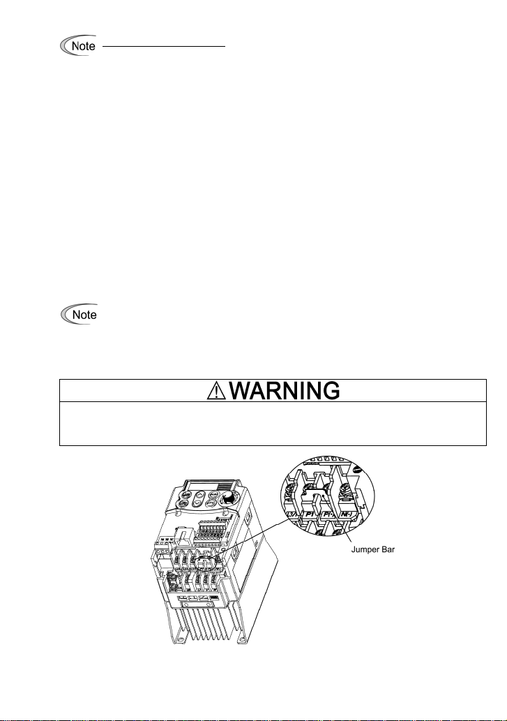
e DC reactor terminals, P1 and P (+)
1) Remove the jumper bar from terminals P1 and P(+).
2) Connect a DC reactor (option) to terminals P1 and P(+).
• The wiring length should be 10 m or below.
• If both a DC reactor and a braking resistor are to be connected to the inverter, secure
both wires of the DC reactor and braking resistor together to terminal P(+). (Refer to
item
f on the next page.)
• Do not remove the jumper bar if a DC reactor is not going to be used.
When wiring the inverter to the pow er supply of 500 kVA or more, be sure to co nnect an optional
DC reactor (DCR).
Otherwise, fire could occur.
Figure 2.4 Location of Jumper Bar
2-9
Page 30

f Braking resistor terminals, P(+) and DB
1) Connect terminals P and DB of a braking resistor (option) to terminals P(+) and DB on the main
circuit terminal block.
2) Arrange the inverter and braking resistor to keep the wiring length to 5 m or less and tw ist the two
wires or route them together in parallel.
Do not connect a braking resistor to any inverter of FRN0002C2S-2/-7 or below. (Even
if connected, the braking resistor will not work.)
Never insert a braking resistor between terminals P(+) and N(-), P1 and N(-), P(+) and P1, DB
and N(-), or P1 and DB.
Doing so could cause fire.
When a DC reactor is not to be connected together with the braking resistor
1) Remove the screws from terminals P(+) and P1, together with the jumper bar.
2) Connect the wire from terminal P of the braking resistor to terminal P(+) of the inverter and put the
jumper bar back into place. Then secure the wire and jumper bar with the screw.
3) Tighten the screw of terminal P1 on the jumper bar.
4) Connect the wire from terminal DB of the braking resistor to the DB of the inverter.
When connecting a DC reactor together with the braking resistor
1) Remove the screw from terminal P(+).
2) Overlap the DC reactor wire and braking resistor wire (P) and then secure them to terminal P(+) o f
the inverter with the screw.
3) Connect the wire from terminal DB of the braking resistor to terminal DB of the inverter.
4) Do not use the jumper bar.
g DC link bus terminals, P (+) and N (-)
These are provided for the DC link bus powered sy stem. Connect these terminals with terminals P(+)
and N (-) of other inverters.
Consult your Fuji Electric representative if these terminals are to be used.
2-10
Page 31

h Main circuit power input ter minals, L1/R, L2/S, and L3/T (for three-phase voltage input)
or L1/L and L2/N (for single-phase voltage input)
1) For safety, make sure that the molded case circuit breaker (M CCB) or magnetic conta ctor (MC) i s
turned off before wiring the main circuit power input terminals.
2) Connect the main circuit power supply wires (L1/R, L2/S and L3/T or L1/L and L2/N) to the input
terminals of the inverter via an MCCB or residual-current-operated protectiv e dev ice (RCD)/earth
leakage circuit breaker (ELCB)*, and MC if necessary.
It is not necessary to align phases of the power supply wires and the input term inals of the inverte r
with each other.
* With overcurrent protection
It is recommended that a magnetic contactor be inserted w hichcan be manually activated.
This is to allow you to disconnect the inv erter from the power supply in an emergency (e.g.,
when the protective function is activate d) so as to prev ent a failure or acciden t from causing
the secondary problems.
2.3.6 Wiring for control circuit terminals
In general, sheaths and covers of the control signal cables and wires are not specifically designed to withstand a high electric field (i.e., reinforced insulation is not applied). Therefore, if a
control signal cable or wire comes into direct contact with a live conductor of the main circuit, the
insulation of the sheath or the cover might break down, which would expose the signal wire to a
high voltage of the main circuit. Make sure tha t the co ntro l signal ca bles and w ires w ill not come
into contact with live conductors of the main circuit.
Failure to observe these precautions could cause electric shock and/or an accident.
Noise may be emitted from the inverter, motor and wires.
Implement appropriate measure to prevent the nearby sensors and device s from malfunctio ning
due to such noise.
An accident could occur.
Table 2.8 lists the symbols, names and functions of the control circuit terminals. The wiring to the
control circuit terminals differs depending upon the setting of the function codes, which reflects the
use of the inverter.
Put back the main circuit terminal block cover and then connect wires to the control cir cuit terminals.
Route these wires correctly to reduce the influence of noise.
2-11
Page 32

Table 2.8 Symbols, Names and Functions of the Control Circuit Terminals
Symbol Name Functions
cation
Classifi-
[13] Power
supply for
potentiometer
[12] Analog
setting
voltage
input
Power supply (+10 VDC) for an external frequency command potentiometer
(Potentiometer: 1 to 5 kΩ)
A potentiometer of 1/2 W rating or more should be connected.
(1) The frequency is commanded according to the external analog input
voltage.
0 to +10 (VDC)/0 to 100 (%) (Normal operation)
+10 to 0 (VDC)/0 to 100 (%) (Inverse operation)
(2) Used for reference signal (PID process command) or PID feedback
signal.
(3) Used as additional auxiliary setting for various main frequency com-
mands.
* Input impedance: 22 kΩ
* The allowable maximum input is +15 VDC; however, the voltage higher
than +10 VDC is treated as +10 VDC.
[C1] Current
Analog input
[11] Analog
input
common
(1) The frequency is commanded according to the external analog input
current.
+4 to +20 mA DC/0 to 100% (Normal operation)
+20 to +4 mA DC/0 to 100% (Inverse operation)
+0 to +20 mA DC/0 to 100% (Normal operation)
+20 to 0 mA DC/0 to 100% (Inverse operation)
(2) Used for reference signal (PID process command) or PID feedback
signal.
(3) Connects PTC (Positive Temperature Coefficient) thermistor for motor
protection.
(4) Used as additional auxiliary setting for various main frequency com-
mands.
* Input impedance: 250Ω
* The allowable maximum input is +30 mA DC; however, the current
larger than +20 mA DC is treated as +20 mA DC.
Common terminal for analog input and output signals
This terminal is electrically isolated from terminals [CM] and [Y1E].
2-12
Page 33

Table 2.8 Symbols, Names and Functions of the Control Circuit Terminals (Continued)
Symbol Name Functions
cation
Classifi-
- These low level analog signals are especially susceptible to the external noise effects.
Route the wiring as short as possible (within 20 m) and use shielded wires. In principle,
ground the shielded sheath of wires; if effects of external inductive noises are considerable, connection to terminal [11] may be effective. As shown in Figure 2.5, ground
the single end of the shield to enhance the shield effect.
- Use a twin- contact relay for low le vel signals if the relay is us ed in the contr ol circuit.
Do not connect the relay's contact to terminal [11].
- When the inverter is connected to an e xternal device outputting analog signals, th e
external device may malfunction due to electric noise generated by the inverter. If this
happens, according to the circumstances, connect a ferrite c ore (a toroidal core or
equivalent) to the device outputting analog signals or connect a capacitor having the
good cut-off characteristics for high frequency between control signal wires as shown
in Figure 2.6.
- Do not apply a voltage of +7.5 VDC or higher to terminal [C1]. Doing so could damage
Analog input
Potentiometer
1 k to 5 kΩ
the internal control circuit.
Figure 2.5 Connection of Shielded Wire Figure 2.6 Example of Electric Noise Reduction
2-13
Page 34

Table 2.8 Symbols, Names and Functions of the Control Circuit Terminals (Continued)
Symbol Name Functions
cation
Classifi-
[X1] Digital
input 1
[X2] Digital
input 2
[X3] Digital
input 3
[FWD] Run
forward
command
[REV] Run
reverse
command
Digital input
[PLC] PLC
signal
power
[CM] Digital
common
(1) The various signals such as "Coast to a stop," "Enable external alar m
trip," and "Select multistep frequency" can be assigned to terminals [X1]
to [X3], [FWD] and [REV] by setting function codes E01 to E03, E98, and
E99. For details, refer to Chapter 5, Section 5.2 "Details of Function
Codes."
(2) Input mode, i.e. Sink/Source, is changeable by using the internal jumper
switch.
(3) Switches the logic value (1/0) for ON/OFF of the terminals between [X1]
to [X3], [FWD] or [REV], and [CM]. If the logic value for ON between [X1]
and [CM] is 1 in the normal logic system, for example, OFF is 1 in the
negative logic system and vice versa.
(4) The negative logic signaling cannot be applicable to [FWD] and [REV].
Digital input circuit specifications
Operation
voltage
(SINK)
Operation
voltage
(SOURCE)
Operation current at ON
(Input Voltage at 0 V)
Allowable leakage
current at OFF
Connects to PLC output signal power supply.
Rated voltage: +24 VDC (Allowable range: +22 to +27 VDC), Max. 50 mA
Common terminal for digital input signals
This terminal is electrically isolated from terminals [11] and [Y1E].
Item Min. Max.
ON level 0 V 2 V
OFF level 22 V 27 V
ON level 22 V 27 V
OFF level 0 V 2 V
2.5 mA 5 mA
- 0.5 mA
2-14
Page 35

Table 2.8 Symbols, Names and Functions of the Control Circuit Terminals (Continued)
Symbol Name Functions
cation
Classifi-
Using a relay contact to turn [X1], [X2], [X3], [FWD] or [REV] ON or OFF
Figure 2.7 shows two examples of a circuit that uses a relay contact to turn control signal
input [X1], [X2], [X3], [FWD] or [REV] ON or OFF. Circuit (a) has a connecting jumper
applied to SINK, whereas circuit (b) has one that is applied to SOURCE.
Note: To configure this kind of circuit, use a highly reliable relay.
(Recommended product: Fuji
control relay Model HH54PW)
(a) With a jumper applied to SINK
(b) With a jumper applied to SOURCE
Figure 2.7 Circuit Configuration Using a Relay Contact
Using a programmable logic controller (PLC) to turn [X1], [X2], [X3], [FWD] or
[REV] ON or OFF
Figure 2.8 shows two examples of a circuit that uses a programmable logic controller
(PLC) to turn control signal input [X1], [X2], [X3], [FWD] or [RE V] ON or O FF. Circuit (a)
Digital input
has a connecting jumper applied to SINK, whereas circuit (b ) has one that is applied t o
SOURCE.
In circuit (a) below, short-circuiting or opening the transistor's open collector circuit in the
PLC using an external power source turns control signal [X1], [X2], [X3], [FWD] or [REV]
ON or OFF. When using this type of circuit, observe the following:
- Connect the + node of the external power source ( which should be isolated fro m the
PLC's power) to terminal [PLC] of the inverter.
- Do not connect terminal [CM] of the inverter to the common terminal of the PLC.
(a) With a jumper applied to SINK
(b) With a jumper applied to SOURCE
Figure 2.8 Circuit Configuration Using a PLC
For details about the jumper setting, refer to Section 2.3.7 "Setting up the jumper switches."
2-15
Page 36

Table 2.8 Symbols, Names and Functions of the Control Circuit Terminals (Continued)
Symbol Name Functions
cation
Classifi-
[FMA] Analog
monitor
The monitor signal for analog DC voltage (0 to +10 VDC) is output. The
signal functions can be selected from the following with function code F31.
- Output frequency (before slip compensation)
- Output frequency (after slip compensation)
- Output current - Output voltage
- Input power - PID feedback amount
- DC link bus voltage - Calibration
Analog output
[11] Analog
common
[Y1] Transistor
output
- PID command (SV) - PID output (MV)
*Input impedance of external device: Min. 5 kΩ
Common terminal for analog input and output signals
This terminal is electrically isolated from terminals [CM] and [Y1E].
(1) Various signals such as "Inverter running," "Freq uency arrival signal"
and "Motor overload early warning" can be assigned to terminal [Y1] by
setting function code E20. Refer to Chapter 5, Section 5. 2 "Details of
Function Codes."
(2) Switches the logic value (1/0) for ON/OFF of the terminals between [Y1]
and [Y1E]. If the logic value for ON between [Y1] and [Y1E] is 1 in th e
normal logic system, for example, OFF is 1 in the negative logic system
and vice versa.
Digital input circuit specification
Transistor output
[PLC] Transistor
output
power
[Y1E] Transistor
output
common
Figure 2.9 shows examples of connection between the control circuit and a
PLC.
- Check the polarity of the external power inputs.
- When connecting a control relay, first connect a
surge-absorbing diode across the coil of the relay.
Power source of +24 VDC to be fed to the transistor output circuit load (50
mA at maximum).
To enable the source, it is necessary to short-circuit between terminals [Y1E]
and [CM].
Can also be used as a 24 VDC power source.
Common terminal for transistor output signal
This terminal is electrically Isolated from terminals [CM] and [11].
2-16
Page 37

Table 2.8 Symbols, Names and Functions of the Control Circuit Terminals (Continued)
Symbol Name Functions
cation
Classifi-
Connecting programmable controller (PLC) to terminal [Y1]
Figure 2.9 shows two examples of circuit connection between the transistor output of the
inverter’s control circuit and a PLC. In example (a), the input circuit of the PLC serves as
a sink for the control circuit, whereas in example (b), it serves as a source for the control
circuit.
Transistor output
[30A],
[30B],
[30C]
Relay contact output
RJ-45 connector
(RS-485)
Communication
(a) PLC serving as sink
Figure 2.9 Connecting PLC to Control Circuit
Alarm
relay
output
(for any
fault)
(1) Outputs a contact signal (SPDT) when a protective function has been
activated to stop the motor.
Contact rating: 250 VAC 0.3A cos φ = 0.3
+48 VDC, 0.5A
(2) A command similar to terminal [Y1] can be selected for the transistor
output signal and use it for signal output.
(3) Switching of the normal/negative logic output is applicable to the fol-
lowing two contact outputs: "Terminals [30A] and [30C] are
short-circuited for ON signal output" or "Terminals [30B] and [30C] are
short-circuited (non-excite) for ON signal output."
(1) Used to connect an optional keypad to the inverter.
(2) Used to connect the inverter to a computer running FRENIC Loader via
the RS-485 communications link. (For the terminating resis tor, refer to
Section 2.3.7.)
* Pins 1, 2, 7 and 8 are exclusively assigned to power lines for an optiona l
keypad. When connecting any other device to the RJ-45 connector, do not
use those pins.
For the location of the RJ-45 connector, refer to Figure 2.11 "Locations
of Jumper Switches and RJ-45 Connector."
(b) PLC serving as source
Figure 2.10 RJ-45 Connector and its Pin Assignment
2-17
Page 38

- Route the wiring of the control terminals as far from the wiring of the main circuit as
possible. Otherwise electric noise may cause malfunctions.
- Fix the control circuit wires inside the inverter to keep them away from the live parts of
the main circuit (such as the terminal block of the main circuit).
- The pin assignment of the RJ-45 connector on the FRENIC-Mini series is different from
that of the RJ-45 connector on the FVR-E11S serieskeypad. Do not connect them with
each other; doing so may cause a short-circu iting or collisi on of signal line s, r esulting in
a broken inverter.
2.3.7 Setting up the jumper switches
Before changing the jumper switches, turn OFF the power and wait at least five minutes. Make
sure that the LED monitor is turned OFF. Further, make sure, using a multimeter or a similar
instrument, that the DC link bus voltage between terminals P (+) and N (-) has dropped to the
safe level (+25 VDC or below).
An electric shock may result if this warning is not heeded as there may be some residual
electric charge in the DC link bus capacitor even after the power has been turned OFF.
Switching the jumper switches (shown in Figure 2.11) allows you to customize the specificatio ns of
the digital I/O terminals and the RS-485 communication terminating resistor.
To access the jumper switches, remove the terminal block covers.
For details on how to remove the terminal block covers, refer to Section 2.3.1.
Table 2.9 lists function of each jumper switch.
Table 2.9 Function of Jumper Switches
Switch Function
SW1 SINK/SOURCE switch for digital input terminals
1
• To use digital input terminals [X1] to [X3], [FWD] and [REV] in the SINK mode, set
a jumper in the sink position, to use them in the SOURCE mode, set a jumper in
the source position. (See Figure 2.11.)
• To switch between SINK and SOURCE modes, use a mini needle-nose pliers or
the similar tool to change the mounting position of the jumper.
SW3 Terminating resistor ON/OFF switch for RS-485 communication
2
• To connect an optional remote keypad, set a jumper in the OFF position (factory
default).
• If the inverter is connected to the RS-485 communications network as a terminating device, set a jumper in the ON position.
• To switch the terminating resistor ON and OFF, use a mini needle-nose pliers or
the similar tool to change the mounting position of the jumper.
2-18
Page 39

Figure 2.11 shows the locations of jumper switches and the RJ-45 connector.
Figure 2.11 Locations of Jumper Switches and
RJ-45 Connector
SINK
1
SW1
(Factory default for
_ _ _ _
FRN
ON
2
SW3
RJ-45 connector
3
C2S-_A, C, U)
SOURCE
(Factory default for
_ _ _ _
FRN
(Factory default for
C2S-_E)
OFF
all inverter types)
2-19
Page 40

2.3.8 Cautions relating to harmonic component, noise, and leakage current (1) Harmonic component
Input current to an inverter includes a harmonic component that may affect other motors and
phase-advancing capacitors on the same pow er supply li ne. If the harmonic component cau ses any
problems, connect a DC reactor (option) to the inverter. In some cases, it is necessary to insert a
reactor in series with the phase-advancing capacitors.
(2) Noise
If noise generated from the inverter affects other devices, or that generated from peripheral
equipment causes the inverter to malfunction, follow the basic measures outlined below.
1) If noise generated from the inverter affects the other devices through power wires or grounding
wires:
- Isolate the grounded metal frames of the inverter from those of the other devices.
- Connect a noise filter to the inverter power wires.
- Isolate the power system of the other devises from that of the inverter with an insulated
transformer.
2) If induction or radio noise generated from the inverter affect s othe r dev ices through pow er wires
or grounding wires:
- Isolate the main circuit wires from the control circuit wires and other device wires.
- Put the main circuit wires through a metal conduit and connect the pipe to the ground near the
inverter.
- Mount the inverter on the metal switchboard and connect the whole board to the ground .
- Connect a noise filter to the inverter power wires.
3) When implementing measures against noise generated from peripheral equipment:
- For the control signal wires, use twisted or shielded-twisted wires. When using
shielded-twisted wires, connect the shield of the shielded wires to the common terminals of
the control circuit.
- Connect a surge absorber in parallel with a coil or solenoid of the magnetic contactor.
(3) Leakage current
A high frequency current component generated by insulated gate bipolar transistors (IGBTs)
switching on/off inside the inverter becomes leakage current through stray capacitance of inverter
input and output wires or a motor. If any of the problems listed below occurs, take appropriate
measures against them.
Table 2.10 Leakage Current Countermeasures
Problem Measures
An earth leakage circuit
breaker* that is connected
to the input (primary) side
has tripped.
*With overcurrent protection
1) Decrease the carrier frequency.
2) Make the wires between the inverter and motor shorter.
3) Use an earth leakage circuit breaker (ELCB) with lower
sensitivity than the one currently used.
4) Use an earth leakage circuit breaker that features measures
against the high frequency current component (Fuji SG and
EG series).
An external thermal relay
was activated.
1) Decrease the carrier frequency.
2) Increase the settling current of the thermal relay.
3) Use the electronic thermal overload protection built in the
inverter.
2-20
Page 41

Chapter 3 OPERATION USING THE KEYPAD
3.1 Names and Functions of Keypad Components
As shown in the figure at right, the
keypad consists of a four-digit
7-segment LED monitor, a potentiometer (POT), and six keys.
The keypad allows you to start and
stop the motor, monitor running
status, configure the function code
data, check I/O signal states, and
display maintenance information and
alarm information.
Potentiometer
and Keys
Monitor,
/
Table 3.1 Names and Functions of Keypad Components
Four-digit, 7-segment LED monitor which displays the following according to the
operation modes *.
In Running mode: Running status information (e.g., output frequency,
In Programming mode: Menus, function codes and their data
In Alarm mode: Alarm code which identifies the error factor if the
Potentiometer (POT) which is used to manually set a reference frequency,
auxiliary frequencies 1 and 2 or PID process command.
RUN key. Press this key to run the motor.
STOP key. Press this key to stop the motor.
UP/DOWN keys. Press these keys to select the setting items and change the
function code data displayed on the LED monitor.
Program/Reset key which switches the operation modes* of the inverter.
In Running mode: Pressing this key switches the inverter to Program-
In Programming mode: Pressing this key switches the inverter to Running
In Alarm mode: Pressing this key after removing the error factor
Function/Data key which switches the operation you want to do in each mode as
follows:
In Running mode: Pressing this key switches the information to be dis-
In Programming mode: Pressing this key displays the function codes and sets
In Alarm mode: Pressing this key displays detailed alarm information.
* FRENIC-Mini features three operation modes: Runnin g, Programming, and Alarm. Refer to Sec tion 3.2
"Overview of Operation Modes."
Program/Reset key
current, and voltage)
protective function is activated.
ming mode.
mode.
switches the inverter to Running mode.
played concerning the status of the inverter (output
frequency, output current, output voltage, etc.).
their data entered with the
POT.
7-segment
LED monitor
Down key Up key Function/Data key
Functions
and keys or the
Potentiometer RUN key
STOP key
3-1
Page 42

Simultaneous keying
Simultaneous keying means pressing two keys at the same time (expressed by "+"). FRENIC-Mini
supports simultaneous keying as listed below.
(For example, the expression "
+ keys" stands for pressing the key while holding down the
key.)
Table 3.2 Simultaneous Keying
Operation mode Simultaneous keying Used to:
Running mode Control entry to/exit from jogging operation.
Programming mode
Alarm mode + keys
+ keys
+ keys
Change certain function code data.
(Refer to function codes F00, H03, H45 and H97 in
Chapter 5 "FUNCTION CODES.")
Switch to Programming mode without clearing
alarms.
About changing of function code data
The function code data can be changed only when the data value displayed on the LED monitor is
flashing.
When the data value is lit, no change is allow ed. To change the data, stop the inverter or disable the
data protection.
3.2 Overview of Operation Modes
FRENIC-Mini features the following three operation modes:
Running mode : This mode allows you to enter run/stop commands in regular operation.
Programming mode : This mode allows you to configure function code data and check a variety
Alarm mode : If an alarm occurs, the inverter automatically enters the Alarm mode. In this
* Alarm code: Indicates the cause of the alarm condition that has trigg ered the protective function. For
details, refer to Chapter 8, Section 8.5 "Protective Functions."
Figure 3.1 shows the status transition of the inverter between these three operation modes.
You can also monitor the running status in real time.
of information relating to the inverter status and maintenance.
mode, you can view the corresponding alarm code* and its related information on the LED monitor.
Figure 3.1 Status Transition between Operation Modes
3-2
Page 43

Figure 3.2 illustrates the transitio n o f t h e LE D monitor screen du rin g t he R u nning mode, the transition between menu items in the Progr amming mode, and t he transition bet ween alarm codes at
different occurrences in the Alarm mode.
*1 In speed monitor, you can display any of the following according to the setting of function code E48:
Output frequency (Hz), Reference frequency (Hz), Load s haft speed (r/min), Line speed (m/min), and
Constant rate of feeding time (min).
*2 Applicable only when PID control is employed.
*3 Applicable only when timer operation is selected by the setting of function code C21.
*4 Applicable only when the remote keypad (option) is connected to the inverter.
*5 Alarm can be reset with the
Figure 3.2 Transition between Basic Display Screens by Operation Mode
key only when the current alarm code is displayed.
3-3
Page 44

3.3 Running mode
When the inverter is turned on, it automatically enters Running mode. In Running mode, you can:
(1) Monitor the running status (e.g., output frequency, output current),
(2) Set up the reference frequency and PID process command, and
(3) Run/stop the motor.
3.3.1 Monitoring the running status
In Running mode, the nine items listed below can be monitored. Immediately after the inverter is
turned ON, the monitor item specified by function code E43 is di splay ed. Pre ss the
between these monitor items.
Table 3.3 Monitor Items
Monitor Items
Speed monitor
Output frequency (before slip
compensation) (Hz)
Output frequency (after slip
compensation) (Hz)
Reference frequency (Hz)
Load shaft speed (r/min)
Line speed (m/min)
Constant feeding rate time
(min)
Output current (A)
Input power (kW)
Output voltage (V) (Note 2)
PID command (Note 3)(Note 4)
PID feedback amount
(Note 3)(Note 5)
PID output (Note 3)(Note 4)
Timer (sec) (Note 3)
Input watt-hour
(Note 1) A value 10000 or above cannot be displayed on the 4- digit LED monitor screen, so " "
appears instead.
(Note 2) When the LED monitor displays an output voltage, the 7-segment letter
stands for the unit of the voltage "V."
Display Sample
on the LED
monitor (Note 1)
Function code E48 specifies what to be displayed on the LED
monitor.
5*00
5*00
5*00
30*0
30*0
50
!90a
*40p
200u
1*0*
)0*
10**
50
10*0
Meaning of Displayed Value
Pre-slip compensation frequency (E48 = 0)
Frequency actually being output (E48 = 1)
Final reference frequency (E48 = 2)
Output frequency (Hz) x E50 (E48 = 4)
Output frequency (Hz) x E50 (E48 = 5)
Current output from the inverter in RMS 3
Input power to the inverter 9
Voltage output from the inverter in RMS 4
PID command/PID feedback amount trans-
formed to the virtual physical value of the object
to be controlled
Refer to function codes E40 and E41.
PID output in %, assuming the maximum fre-
quency (F03) as 100%
Remaining effective timer count 13
Display value =
(Note 3) These PID related items appear only under PID control (J01 = 1 or 2).
The timer (for timer operation) appears only when timer operation is enabled (C21 = 1).
When the PID control or timer operation is disabled, "----" appears instead.
(Note 4) When the LED monitor displays a PID command or its output amount, the dot (decimal point)
attached to the lowest digit of the 7-segment letter blinks.
(Note 5) When the LED monitor displays a PID feedback amount, the d ot (decimal point) attached to the
lowest digit of the 7-segment letter lights.
3-4
key to switch
Function
Code Data
for E43
0
(E48 = 6)
10
12
14
u
in the lowest digit
25
Page 45

r
y
3.3.2 Setting up reference frequency and PID process command
You can set up the desired frequency command and PID process command by using the potentiometer and
quency, load shaft speed, l ine speed, and con stant rate of feeding time by setting func tion code E48.
Setting up the reference frequency
Using the built-in potentiometer (factory default)
Setting function code F01 to "4: Built-in potentiometer (POT)" (factory default) allows you to specify
the reference frequency using the potentiometer.
Using the
(1) Set function code F01 to "0:
Alarm mode, the
Running mode.
(2) Press the
(3) To change the reference frequency, press the
automatically saved into the inverter’s memory . It i s kept there even if the inv erter is powered off,
and it will be used as the initial frequency next time the inverter is powered on.
Setting up the PID process command
To enable PID control, you need to set function code J01 to "1" or "2."
and keys on the keypad. You can also set up the reference frequency as fre-
and keys
/ keys cannot be used for setting the reference frequency, so switch to
or key to display the reference frequency with the lowest digit blinking.
• If you have set the function code F01 to "0: / keys on the built-in keypad" but have
selected a frequency setting other than frequency 1 (i.e., frequency 2, Via communications, or Multistep frequency), then the
reference frequency even if the keypad is in Running mode. Pressing ei ther of these keys
will just display the currently selected reference frequency.
• When you start changing the reference frequency or any other parameter with the
key, the lowest digit on the d isplay will blink and start chan ging. As you are holding the
key down, blinking will gradually move to the upper digit places and the upper digits will
be changeable.
• If you press the
second after the lowest digit st arts blinking , blinking will mov e to the next up per digit place
to allow you to change the value of that digit (curso r movement) . This w ay you can easil
change the values of the higher digits.
• By setting function code C30 to "0:
frequency set 2 as the frequency setting method, you can also specify or change the
reference frequency in the same manner using the
Refer to the FRENIC-Min i User's Manual for details on the PID control.
/ keys on the built-in keypad." In Programming mode or
or key again. The new setting will be
or key cannot be used for setting up the
or key once and then hold down the key for more than 1
/ keys on the built-in keypad" and selecting
and keys.
o
3-5
Page 46

Setting the PID process command with the built-in potentiometer
(1) Set function code E60 to "3: PID process command 1."
(2) Set function code J02 to "1: PID process command 1."
Setting the PID process command with the
(1) Set function code J02 to "0:
/ keys on the built-in keypad."
and keys
(2) Set the LED monitor to an item other than the speed monitor (E43 = 0) in Running mode. In
Programming mode or Alarm mode, the
/ keys cannot be used for setting the PID
process command, so switch to Running mode.
(3) Press the
or key to display the PID process command. The lowest digit of the displayed
command and the decimal point blink.
(4) To change the PID process command, press the
or key again. The new PID process
command will be automatically saved into the inverter’s memory. It is kept there even if the
inverter is switched to any other PID process command entry method and then returned to the
keypad entry method. Al so, i t i s kept there ev en if the inv erter is pow ered off, and it will be used
as the initial PID process command next time the inverter is powered on.
• Even if multistep frequency is selected as a PID process command (SS4 = ON), you still
can set the process command using the keypad.
• When function code J02 data has been set to any value except "0," pressing the
or
key displays the currently selected PID process command but does not allow any
change of the setting.
• When a PID process command is displayed, the decimal point next to the low est digit on
the LED display blinks to distinguish it from the regular frequency setting. When a PID
feedback amount is displayed, the decimal point is lit.
3-6
Page 47

3.3.3 Running/stopping the motor
By factory default, pressing the
key starts
running the motor in the forward direction and
pressing the
The
key decelerates the motor to stop.
key is enabled only in Running mode.
By changing the setting of function code F02, you
can change the starting direction of motor rotation;
for example, you can have the motor start running
in the reverse di rection or in accord ance with the
wiring connection at the terminal block.
Operational relationship between function code F02 (Operation method) and
T able 3.4 li sts the relationship b etween function code F02 setti ngs and the
key, which determines
the motor rotation direction.
Table 3.4 Rotation Direction of Motor, Specified by F02
If Function code F02
is set to:
Pressing the
rotates the motor:
2 in the forward direction
3 in the reverse direction
key
(Note) The rotation direction of
IEC-compliant motors is opposite to the one shown here.
For the details of operation with function code F02 set to "0" or "1," refer to Chapter 5.
key
3-7
Page 48

3.4 Programming mode
Programming mode provides you with these functions--setting and checking function code data,
monitoring maintenance information and checking input/ou tput (I/O) signal status. The functions can
be easily selected with the menu-driven system. Table 3.5 lists menus available in Programming
mode. The leftmost digit (numerals) of each letter string indicates the corresponding menu number
and the remaining three digits indicate the menu contents.
When the inverter enters Programming mode from the second time on, the menu that was selected
last in Programming mode will be displayed.
Table 3.5 Menus Available in Programming Mode
Menu # Menu
#1 "Data setting"
#2 "Data checking"
#3 "Drive monitoring"
#4 "I/O checking"
"Maintenance
#5
information"
"Alarm informa-
#6
tion"
"Data copying"
#7
*
LED
monitor
shows:
!f__
!e__
!c__
!p__
!h__
!a__
!j__
!y__
"rep
#ope
$i_o
%che
'cpy
F codes
(Fundamental functions)
E codes
(Extension terminal functions)
C codes
(Control functions of frequency)
P codes
(Motor 1 parameters)
H codes
(High performance functions)
A codes
(Motor 2 parameters)
J codes
(Application functions)
y codes (Link functions)
Displays only function codes that have been
changed from their factory defaults. You may refer to
or change those function codes data.
Displays the running information required for maintenance or test running.
Displays external interface information.
Displays maintenance information including accumulated run time.
Displays the latest four alarm codes. You may refer
&al
to the running information at the time when the alarm
occurred.
Allows you to read or write function code data, as
well as verifying it.
Main functions
Selecting each of
these function
codes enables its
data to be displayed/changed.
Refer
to:
Section
3.4.1
Section
3.4.2
Section
3.4.3
Section
3.4.4
Section
3.4.5
Section
3.4.6
--
*To use this function, a remote keypad (option) is required.
3-8
Page 49

Figure 3.3 illustrates the menu transition in Programming mode.
* Displayed only when a remote keypad (option) is set up for use.
Figure 3.3 Menu Transition in Programming Mode
Limiting menus to be displayed
The menu-driven system has a limiter function (specified by function code E52) that limits menus to
be displayed for the purpose of simple operation. The factory default is to display Menu #1 "Data
setting" only, allowing no switching to any other menu.
Table 3.6 Function Code E52 – Keypad (Mode Selection)
Function code data (E52) Menus selectable
0: Function code data editing mode Menu #1 "Data setting" (factory default)
1: Function code data check mode Menu #2 "Data checking"
2: Full-menu mode Menu #1 through #6
Note: Menu #7 appears only when the remote keypad (option) is connected.
3-9
Page 50

If the full-menu mode is selected, pressing the or key will cycle through the menus.
With the
key, you can select the desired menu item. Once the entire menu has been
cycled through, the display will return to the first menu item.
3.4.1 Setting up the function codes – "Data Setting"
Menu #1 "Data setting" in Programming mode allows you to set function codes for making the
inverter functions match your needs.
To set function codes in Menu #1 "Data setting," it is necessary to set function code E52 data to "0"
(Function code data editing mode) or "2" (Full-menu mode).
The table below lists the function codes available in the FRENIC-Mini. The function codes are
displayed on the LED monitor on the keypad as shown below.
ID number in each function code group
Function code group
Table 3.7 List of FRENIC-Mini Function Codes
Function code
group
F codes F00 to F51 Fundamental functions To be used for basic motor running.
E codes E01 to E99 Extension terminal
C codes C01 to C99 Control functions of
P codes P02 to P99 Motor 1 parameters To be used to set special parameters for
H codes H03 to H98 High performance
A codes A01 to A52 Motor 2 parameters To be used to set specific parameters
J codes J01 to J72 Application functions To be used for PID control and brake
y codes y01 to y99 Link functions To be used for communications
Refer to Chapter 5 "FUNCTION CODES" for details on the function codes.
Function code Function Description
functions
frequency
functions
To be used to select the functions of the
control circuit terminals.
To be used to set functions related to
the LED monitor display.
To be used to set application functions
related to frequency settings.
the motor capacity, etc.
To be used for high added value func-
tions and complicated control, etc.
for the motor capacity, etc.
signals.
3-10
Page 51

Figure 3.4 shows the status transition for Menu #1 "Data setting."
Figure 3.4 "Data Setting" Status Transition
3-11
Page 52

Basic key operation
This section gives a description of the basic key operation, following the example of the function
code data changing procedure shown in Figure 3.5.
This example shows you how to change function code F01 data from the factory default "Built-in
potentiometer (POT) (F01 = 4)" to "
(1) When the inverter is powered on, it automatically enter s Running mode . In that mode , press the
key to switch to Programming mode. The function selection menu appears.
(2) With the menu displayed, use the
this example, select
(3) Press the
this example, function code
Even if the function code list for a particular function code group is displayed, it is possible to
transfer the display to a different function code group using the
(4) Select the desired function code using the
example, select function code
The data of this function code appears. (In this example, data "
(5) Change the function code data using the
four times to change data
(6) Press the
saue
The
will return to the function code list, then move to the nex t function code . (In this ex ample,
Pressing the
reverts to the previous value, the display returns to the function code list, and the original func-
tion code reappears.
(7) Press the
<Cursor movement>
You can move the cursor when changing function code data by holding down the
for 1 second or longer in the same way as with the frequency settings.
!f__
key to proceed to the function code s in the function code gr oup sele cted i n (2). ( In
key to establish the function code data.
appears and the data will be saved in the memory inside the inverter. The display
key instead of the key cancels the change made to the data. The data
key to return to the menu from the function code list.
/ keys on the built-in keypad (F01 = 0)."
and keys to select the desired function code group. (In
).
f 00
appears.)
and keys and press the key. (In this
f 01
.)
and keys. (In this example, press the key
4
to 0.)
and keys.
4"
of f 01 appears.)
f 02
key
.)
3-12
Page 53

Figure 3.5 Example of Function Code Data Changing Procedure
3.4.2 Checking changed function codes – "Data Checking"
Menu #2 "Data checking" in Programming mode allows you to check function codes that have been
changed. Only the function codes whose data has been changed from the factory defaults are
displayed on the LED monitor. You may refer to the function code data and change it again if necessary. Figure 3.6 shows the status transition diagram for "Data checking."
3-13
Page 54

Figure 3.6 "Data Checking" Status Transition (When changes are made only to F01, F05, E52)
* Pressing the key with the e 52 data displayed returns to f
Basic key operation
The basic key operation is the same as for "Data setting."
To check function codes in Menu #2 "Data checking," it is necessary to set function code
E52 to "1" (Function code data check mode) or "2" (Full-menu mode).
For details, refer to "Limiting menus to be displayed
" on page 3-9.
3-14
01
.
Page 55

3.4.3 Monitoring the running status – "Drive Monitoring"
Menu #3 "Drive monitoring" is used to check the running st atus during maintenance and test running.
The display items for "Drive monitoring" are li sted in Table 3.8. Figure 3.7 shows the status transition
diagram for "Drive monitoring."
Figure 3.7 "Drive Monitoring" Status Transition
3-15
Page 56

Basic key operation
Before checking the running status on the drive monitor, set function code E52 to "2" (Full-menu
mode).
(1) When the inverter is powered on, it automatically enter s Running mode . In that mode , press the
key to switch to Programming mode. The function selection menu appears.
(2) With the menu displayed, use the
(3) Press the
(4) Use the
key to display the desired code in the monitoring item list (e.g.
and keys to select the desired monitoring item, then press the key.
and keys to select "Drive monitoring" (
3_00
#ope
).
).
The running status information for the selected item appears.
(5) Press the
key to return to the monitoring item list. Press the key again to return to the
menu.
Table 3.8 Drive Monitoring Display Items
LED
monitor
shows:
3_00
3_01
3_02
3_03
3_05
3_06
3_07
3_09
3_10
3_11
Contents Unit Description
Output frequency Hz Output frequency before slip compensation
Output frequency Hz Output frequency after slip compensation
Output current A Present output current
Output voltage V Present output voltage
Reference
frequency
Running direction N/A
Running status N/A
Load shaft speed
(line speed)
PID process
command
PID feedback
value
Hz Present reference frequency
Displays the running direction being outputted.
F: forward; R: reverse, – – – –: stop
Displays the running status in hex. format. Refer to "Displaying
running status" on the next page.
The unit for load shaft speed is r/min and that for line speed is
m/min.
Display value = (Output frequency Hz before slip compensation)
× (Function code E50)
r/min
(m/min)
N/A
N/A
appears for 10,000 (r/min or m/min) or more. When
is displayed, the data is overflowing, which means that the function code should be reviewed. For example:
Load shaft speed = Displayed data × 10 (r/min)
The command is displayed through the use of function code E40
and E41 data (PID display coefficients A and B).
Display value = (PID process command) × (Coefficient A - B) + B
If PID control is disabled, "– – – –" appears.
This value is displayed through the use of function code E40 and
E41 data (PID display coefficients A and B).
Display value = (PID feedback value) × (Coefficient A - B) + B
If PID control is disabled, "– – – –" appears.
3-16
Page 57

Displaying running status
T o display the runni ng st atus in hexadecimal format, each st ate ha s been a ssigned to bits 0 to 15 as
listed in Table 3.9. Table 3.10 shows the relationship between each of the status assignments and
the LED monitor display. Table 3.11 gives the conversion table from 4-bit binary to hexadecimal.
Table 3.9 Running Status Bit Allocation
Bit Notation Content Bit Notation Content
15 BUSY
"1" when function code data is
being written.
7 VL "1" under voltage limiting control.
14 Al ways "0." 6 TL Always "0."
WR
13
12 RL
Always "0." 5 NUV
"1" when communication is en-
abled (when ready for run and
frequency commands via communications link).
4 BRK Always "0."
11 ALM "1" when an alarm has occurred. 3 INT
"1" when the DC link bus voltage is
higher than the undervoltage level.
"1" when the inverter output is shut
down.
10 DEC "1" during deceleration. 2 EXT "1" during DC braking.
9 ACC "1" during acceleration. 1 REV
8 IL "1" under current limiting control. 0 FWD
"1" during running in the reverse
direction.
"1" during running in the forward
direction.
Table 3.10 Running Status Display
LED No. LED4 LED3 LED2 LED1
Bit 15 14 13 12 11 10 9 8 7 6 5 4 3 2 1 0
Notation BUSY WR RL ALM DEC ACC IL VL TL NUV BRK INT EXT REV FWD
Binary 1 0 0 0 0 0 1 1 0 0 1 0 0 0 0 1
Hexa-
decimal
(See Table
3.11.)
Hexa-
Example
decimal
on the
LED
monitor
8 3 2 1
3-17
Page 58

Hexadecimal expression
A 4-bit binary number can be expressed in hexadecimal format (1 hexadecimal digit). Table 3.11
shows the correspondence between the tw o notations. The hex adecimals are shown a s they appear
on the LED monitor.
Table 3.11 Binary and Hexadecimal Conversion
Binary Binary
Eight's
Four's
place
Two's
place
place
0 0 0 0
0 0 0 1
0 0 1 0
0 0 1 1
0 1 0 0
0 1 0 1
0 1 1 0
0 1 1 1
One's
place
Hexadecimal
0
1
2
3
4
5
6
7
Eight's
Four's
Two's
place
place
1 0 0 0
1 0 0 1
1 0 1 0
1 0 1 1
1 1 0 0
1 1 0 1
1 1 1 0
1 1 1 1
place
One's
place
Hexadecimal
8
9
a
b
c
d
e
f
3-18
Page 59

3.4.4 Checking I/O signal status – "I/O Checking"
With Menu #4 "I/O checking," you can display the I/O status of external signals without using a
measuring instrument. External signals that can be displayed include digital I/O signals and analog
I/O signals. Table 3.12 lists check items available. The status transition for I/O checking is shown in
Figure 3.8.
Figure 3.8 "I/O Checking" Status Transition
3-19
Page 60

Basic key operation
Before checking the status of the I/O signals, set function code E52 to "2" (Full-menu mode).
(1) When the inverter is powered on, it automatically enter s Running mode . In that mode , press the
key to switch to Programming mode. The function selection menu appears.
(2) With the menu displayed, use the
(3) Press the
(4) Use the
key to display the codes for the I/O check item l ist. (e.g.
and keys to select the desired I/O check item, then press the key.
and keys to select "I/O check" (
$i_o
4_00
).
)
The corresponding I/O check data appears. For control I/O signal terminal and control circuit
terminal input under communication control, use the
and keys to select one of the two
different display methods.
(5) Press the
key to return to the I/O check item list. Press the key again to return to the
menu.
Table 3.12 I/O Check Items
LED monitor
shows:
4_00
4_01
4_02
4_03
4_04
I/O signals on the control
circuit terminals
I/O signals on the control
circuit terminals under
communication control
Input voltage on terminal [12] Shows the input voltage on terminal [12] in volts (V).
Input current on terminal [C1]
Output voltage to analog
meters [FMA]
Contents Description
Shows the ON/OFF state of the digital I/O terminals.
Refer to "Displaying control I/O signal terminals
below for details on the display contents.
Shows the ON/OFF state for the digital I/O terminals
that received a command via RS-485 communications. Refer to "Displaying control I/O signal ter-
minals" and "Displaying control I/O signal terminals under communication control" below for de-
tails of the item displayed.
Shows the input current on terminal [C1] in milliamperes (mA).
Shows the output voltage on terminal [FMA] in volts
(V).
"
Displaying control I/O signal terminals
The status of control I/O signal terminals may be displayed with ON/OFF of the LED segment or in
hexadecimal display.
Display I/O signal status with ON/OFF of the LED segment
As shown in Table 3.13 and the figure below, each of the segments "a" to "e" on LED1 lights when
the corresponding digital input terminal ([FWD], [REV], [X1], [X2], or [X3]) is short-circuited with
terminal [CM] or [PLC]*, and does not light when it is open. Segment "a" on LED3 lights when the
circuit between output terminals [Y1] and [Y1E] is clo sed and doe s not lig ht when th e circuit is open.
Segment "a" on LED4 is for terminal [30ABC]. Segment "a" on LED4 light s when the circuit be tween
terminals [30C] and [30A] is short-circuited (ON) and does not light when it is open.
* Terminal [CM] if the jumper switch is set for SINK; terminal [PLC] if the jumper switch is set for SOURCE.
• If all terminal input signals are OFF (open), segment "g" on all of LEDs 1 to 4 will light
("– – – –").
• Refer to Chapter 5 "FUNCTION CODES" for details.
3-20
Page 61

Table 3.13 Segment Display for External Signal Information
Segment LED4 LED3 LED2 LED1
1
FWD-CM or
FWD-PLC *
REV-CM or
REV-PLC *
X1-CM or
2
X1-PLC *
X2-CM or
2
X2-PLC *
X3-CM or
2
X3-PLC *
—
a 30ABC Y1-Y1E —
b — — —
c — — —
d — — —
e — — —
f — — (XF) *1 —
g — — (XR) *1 —
dp — — (RST) *
—: No corresponding control circuit terminal exists.
*1 (XF), ( XR), and (RST) are assigned for communication. Refer to "Displaying control I/O signal
terminals under communication control" on the next page.
*2 Terminal [CM] if the jumper switch is set for SINK; terminal [PLC] if the jumper switch is set for SOURCE.
Displaying I/O signal status in hexadecimal format
Each I/O terminal is assigned to bit 15 through bit 0 as shown in Table 3.14 An unassigned bit is
0
interpreted as "0." Alloca ted bit da t a i s display ed on the LED monito r in 4 hex adecimal digits ("
"
f
" each).
" to
With the FRENIC-Mini, digital input terminals [FWD] and [REV] are assigned to bit 0 and bit 1,
respectively. Terminals [X1] through [X3] are assigned to bits 2 through 4. The bit is set to "1" when
the corresponding input terminal is short-circuite d with terminal [CM] or terminal [P LC] *, and is set to
"0" when it is open. For example, when [FWD] and [X1] are on (short-circuited) and all the others are
off (open), "
* Terminal [CM] if the jumper switch is set for SINK; terminal [PLC] if the jumper switch is set for SOURCE.
0005
" is displayed on LED4 to LED1.
Digital output terminal [Y1] is assigned to bit 0. Bit 0 i s set to "1" w hen thi s term inal is shor t- circui te d
with [Y1E], and to "0" when it is open. The status of the relay contact output terminal [30ABC] is
assigned to bit 8. It is set to "1" when the circuit between output terminals [30A] and [30C] is closed
and to "0" when the circuit between [30 B] and [30C ] is cl osed. For example, i f [Y1] is on and [30A] is
connected to [30C], then "
0101
" is displayed on the LED4 to LED1.
Table 3.14 presents an example of bit assignment and corresponding hexadecimal display on the
7-segment LED.
2
2
3-21
Page 62

Table 3.14 Segment Display for I/O Signal Status in Hexadecimal Format
LED No. LED4 LED3 LED2 LED1
Bit 15 14 13 12 11 10 9 8 7 6 5 4 3 2 1 0
Input
(RST)*
terminal
Output
terminal
Binary 0 0 0 0 0 0 0 0 0 0 0 0 0 1 0 1
Hexa-
decimal
(See Table
3.11.)
Hexa-
Example
decimal
on the
LED
monitor
* (XF), (XR), and (RST) are assigned for communication. Refer to "Displa ying control I/O signal termi-
nals under communication control."
(XR)* (XF)* - - - - - - - - X3 X2 X1 REV FWD
- - - - - - -
0 0 0 5
30AC
- - - - - - - Y1
– : No corresponding control terminal exists.
Displaying control I/O signal terminals under communication control
During control via communication, input commands sent through the RS-485 communications link
can be displayed in two ways: "display with ON/OFF of the LED segment" and "in hexadecimal
format." The content to be displayed is basically the same as that for the control I/O signal terminal
status display; however, (XF), (XR), and (RST) are added as inputs. Note that under communications control, I/O display is in normal logic (using the original signals that are not inverted).
Refer to the RS-485 Communication User's Manual (MEH448) for details on input commands
sent through the RS-485 communications link.
3-22
Page 63

3.4.5 Reading maintenance information – "Maintenance Information"
Menu #5 "Maintenance information" in Programming mode contains information necessary for
performing maintenance on the inverter. Table 3.15 lists the maintenance information display items
and Figure 3.9 shows the status transition for maintenance information.
Figure 3.9 "Maintenance Information" Status Transition
Basic key operation
Before viewing maintenance information, set function code E52 to "2" (Full-menu mode).
(1) When the inverter is powered on, it automatically enters Running mode. In that mode, press the
key to switch to Programming mode. The function selection menu appears.
(2) With the menu displayed, use the
(3) Press the
(4) Use the
key to display the list of maintenance item codes (e.g.
and keys to select the desired maintenance item, then press the key.
and keys to select "Maintenance information" (
5_00
).
%che
).
The data of the corresponding maintenance item appears.
(5) Press the
key to return to the list of maintenance items. Press the key again to return to
the menu.
3-23
Page 64

LED Monitor
shows:
5_00
5_01
5_03
5_04
5_05
5_06
5_07
5_08
5_09
Table 3.15 Maintenance Display Items
Contents Description
Shows the cumulative power-ON time of the inverter.
Unit: 1,000 hours.
Cumulative run
time
DC link bus
voltage
Max. temperature
of heat sink
Max. effective
current
Capacitance of
the DC link bus
capacitor
Cumulative run
time of electrolytic
capacitors on the
printed circuit
boards
Cumulative run
time of the
cooling fan
Number of
startups
Input watt-hour
When the total ON-time is less than 10,000 hours (display: 0.001 to
9.999), data is shown in units of one hour.
When the total time is 10,000 hours or more (display: 10.00 to 65.53),
it is shown in units of 10 hours. When the total time exceeds 65535
hours, the display will be reset to "0" and the count will start again.
Shows the DC link bus voltage of the inverter.
Unit: V (volts)
Shows the maximum temperature of the heat sink for every hour.
Unit: ºC
Shows the maximum effective current for every hour.
Unit: A (amperes)
Shows the current capacitance of the DC link bus capacitor, based on
the capacitance when shipping as 100%. Refer to Chapter 7
"MAINTENANCE AND INSPECTION" for details.
Unit: %
Shows the cumulative time during which a voltage is applied to the
electrolytic capacitors on the printed circuit boards.
Unit: 1,000 hours (Display range: 0.01 to 99.99)
When the count is less than 99,990 hours (Display: 0.01 to 99.99), it is
possible to check data in units of 10 hours (0.01).
When the count exceeds 99,990 hours, it stops and the L ED m onitor
sticks to 99.99.
Shows the cumulative run time of the cooling fan.
If the cooling fan ON/OFF control (function code H06) is enabled, the
time when the fan is stopped is not counted.
Unit: 1,000 hours (Display range: 0.01 to 99.99)
When the count is less than 99,990 hours (Display: 0.01 to 99.99), it is
possible to check data in units of 10 hours (0.01).
When the count exceeds 99,990 hours, it stops and the L ED m onitor
sticks to 99.99.
Shows the cumulative count of times the inverter is started up (i.e., the
number of run commands issued).
1.000 indicates 1,000 times. When any number ranging from 0.001 to
9.999 is displayed, the count increases by 0.001 per startup, and
when any number from 10.00 to 65.53 is displayed, the count increases by 0.01 every 10 startups.
If the count exceeds 65,535, it will be reset to "0" and start over again.
Shows the input watt-hour of the inverter.
Unit: 100 kWh (Display range: 0.001 to 9999)
Depending on the value of input watt-hour, the decimal point on the
LED monitor shifts to show it within the LED monitors’ resolution
(Display resolution: 0.001 → 0.01 → 0.1 → 1).
To reset the integrated input watt-hour and its data, set function code
E51 to "0.000."
When the count exceeds 1,000,000 kWh, it will be reset to "0."
3-24
Page 65

LED Monitor
shows:
5_10
5_11
5_12
5_14
5_16
5_23
5_31
5_35
Table 3.15 Maintenance Display Items (Continued)
Contents Description
Shows the value expressed by "input watt-hour (kWh) × E51 (whose
data range is 0.000 to 9,999)."
Unit: None.
Input watt-hour
data
No. of RS-485
errors
RS-485 error
contents
Inverter's ROM
version
Keypad's ROM
version
Cumulative run
time of motor
Remaining time
before the next
motor 1 maintenance
Remaining
startup times
before the next
maintenance
(Display range: 0.001 to 9999. The count cannot exceed 9999 . It will
be fixed at 9,999 once the calculated value exceeds 9999.)
Depending on the value of integrated input watt-hour data, the
decimal point on the LED monitor shifts to show it within the LED
monitors’ resolution.
To reset the integrated input watt-hour data, set function code E51 to
"0.000."
Shows the total number of errors that have occurred in RS-485
communication after the power is turned ON.
Once the count exceeds 9.999, it will be reset to "0."
Shows the latest error that has occurred in RS-485 communication in
decimal format.
For error contents, refer to the RS-485 Communication User's Manual
(MEH448).
Shows the inverter's ROM version as a 4-digit code.
Shows the keypad's ROM version as a 4-digit code. (Available only
when an optional remote keypad is connected.)
Shows the content of the cumulative run time of the motor.
The display method is the same as for "Cumulative run time" (
Shows the time remaining before the next maintenance, which is
estimated by subtracting the cumulative run time of motor 1 from the
maintenance interval specified by H78. (This function applies to motor
1 only.)
Display range: 0 to 9999 The x10 LED turns ON.
Available in the ROM version 0500 or later.
Shows the startup times remaining before the next maintenance,
which is estimated by subtracting the number of startups from the
preset startup count for maintenance specified by H79. (This function
applies to motor 1 only.)
The display method is the same as for
Available in the ROM version 0500 or later.
Time remaining before the next maintenance (hour) =
Displayed value × 10
5_08
above.
5_00
).
3-25
Page 66

3.4.6 Reading alarm information – "Alarm Information"
Menu #6 "Alarm information" in Programming mode shows the causes of the past 4 alarms as an
alarm code. Further, it is also possible to display alarm information that indicates the status of the
inverter when the alarm condition occurred. Figure 3.10 shows the status transition of the alarm
information and Table 3.16 lists the details of the alarm information.
Figure 3.10 "Alarm Information" Status Transition
3-26
Page 67

Basic key operation
Before viewing alarm information, set function code E52 to "2" (Full-menu mode).
(1) When the inverter is powered on, it automatically enter s Running mode . In that mode , press the
key to switch to Programming mode. The function selection menu appears.
(2) With the menu displayed, use the
(3) Press the
key to display the alarm list code (e.g.
and keys to select "Alarm information" (
!0l1
).
&al
).
In the list of alarm codes, the alarm information for the last 4 alarms is saved as an alarm history.
(4) Each time the
recent one as
(5) While the alarm code is displayed, press the
number (e.g.
proximately 1 second. You can also have the item number (e.g.
current) for any other item displayed using the
(6) Press the
LED monitor
shows:
(item No.)
6_00
6_01
6_02
6_03
6_04
6_05
6_06
6_07
6_08
6_09
or key is pressed, the last 4 alarms are displayed in order from the most
!
, " , # , and $ .
key to have the corresponding alarm item
6_00
) and data (e.g. Output frequency) displayed alternately in intervals of ap-
6_01
) and data (e.g. Output
and keys.
key to return to the alarm list. Press the key again to return to the menu.
Table 3.16 Alarm Information Displayed
Contents Description
Output frequency Output frequency before slip compensation
Output current Present output current
Output voltage Present output voltage
Calculated torque Calculated motor output torque
Reference frequency Present reference frequency
Rotational direction
Running status
Cumulative run time
No. of startups
DC link bus voltage
This shows the running direction being output.
f
: forward; r: reverse;
This shows the running status in hexadecimal. Refer to Dis-
playing running status in Section 3.4.3 "Monitoring the running
status."
Shows the cumulative power-ON time of the inverter.
Unit: thousands of hours.
When the total ON-time is less than 10000 hours (display: 0.001
to 9.999), data is shown in units of one hour. When the total time
is 10000 hours or more (display: 10.00 to 65.53), it is shown in
units of 10 hours. When the total time exceeds 65535 hours, the
display will be reset to "0" and the count will start again.
The cumulative total number of times an inverter run command
has been issued is calculated and displayed.
1.000 indicates 1000 times. When any number ranging from
0.001 to 9.999 is displayed, the display increases by 0.001 per
startup, and when any number from 10.00 to 65.53 is displayed,
the display increases by 0.01 every 10 startups.
When the total number exceeds 65535, the counter will be reset
to "0" and start over again.
Shows the DC link bus voltage of the inverter's main circuit.
Unit: V (volts)
----
: stop
3-27
Page 68

Table 3.16 Alarm Information Displayed (Continued)
LED monitor
shows:
(item No.)
6_11
6_12
6_13
6_14
6_15
6_16
6_17
6_18
6_19
6_20
6_21
6_22
6_24
When the same alarm occurs repeatedly in succession, the alarm information for the first
occurrence is retained and the information for the subsequent occurrences is discarded.
Contents Description
Max. temperature of
heat sink
Terminal I/O signal
status (displayed with
the ON/OFF of LED
segments)
Signal input terminal
status (in hexadecimal
format)
Terminal output signal
status (in hexadecimal
format)
No. of consecutive
occurrences
Overlapping alarm 1
Overlapping alarm 2
Terminal I/O signal
status under communication control
(displayed with the
ON/OFF of LED segments)
Terminal input signal
status under communication control
(in hexadecimal format)
Terminal output signal
status under communication control
(in hexadecimal format)
Error sub code Secondary error code for the alarm.
Running status 2
Running status 3
Shows the temperature of the heat sink.
Unit: ºC
Shows the ON/OFF status of the digital I/O terminals. Refer to
"Displaying control I/O signal terminals
"Checking I/O signal status" for details.
This is the number of times the same alarm occurs consecutively.
Simultaneously occurring alarm codes (1)
(
---
is displayed if no alarms have occurred.)
Simultaneously occurring alarm codes (2)
(
---
is displayed if no alarms have occurred.)
Shows the ON/OFF status of the digital I/O terminals under
RS-485 communication control. Refer to "Displaying control
I/O signal terminals under communication control" in Section 3.4.4 "Checking I/O signal status" for details.
Shows the running status 2 in hexadecimal format.
For details, see the next page.
Shows the running status 3 in hexadecimal format.
For details, see the next page.
" in Section 3.4.4
Only the number of consecutive occurrences will be updated.
3-28
Page 69

Table 3.17 Running Status 2 (
Bit Content Bit Content
Drive motor type
0: Induction moto r,
15
1: Permanent magnet synchronous
motor (PMSM)
14 6
13 5
12 4
(Not used.)
11 3
10 2
9
Rotation direction limitation
8
0: Enable, 1: Disable
6_22
) Bit Assignment
7
(Not used.)
Motor selection
00: Motor 1
01: Motor 2
Inverter drive control
0000: V/f control with slip compensa-
1
0
tion inactive
0001: Dynamic torque vector control
0010: V/f control with slip compensa-
tion active
Table 3.18 Running Status 3 (
Bit Notation Content Bit Notation Content
15 - (Not used.) 7 - (Not used.)
14 ID2 Current detected 2 6 - (Not used.)
13 IDL Low current detected 5 OL Motor overload early warning
12 ID Current detected 4 IPF
11 OLP Overload prevention control 3 SWM2 Motor 2 selected
10 LIFE Lifetime alarm 2 - (Not used.)
9 OH Heat sink overheat early warning 1 FDT Frequency detected
8 TRY Auto-resetting 0 FAR Frequency arrival signal
6_24
) Bit Assignment
Auto-restarting after momentary
power failure
3-29
Page 70

r
3.5 Alarm mode
When an abnormal condition occurs, the protective function is invoked to issue an alarm, and the
inverter automatically switches to Alarm mode and displays the corresponding alarm code on the
LED monitor.
Releasing the Alarm and Transferring the Inverter to Running Mode
Remove the cause of the alarm and press the
mode. The alarm can be removed using the
key to release the alarm and return to Running
key only when the current alarm code is displayed.
Displaying the Alarm History
It is possible to display the most recent 3 alarm codes in addition to the one currently displayed.
Previous alarm codes can be display ed by pressing the
or key while the current alarm code is
displayed.
Displaying the Status of Inverter at the Time of Alarm
If an alarm occurs, you can check various running status information (output frequency, output
current, etc.) by pressing the
key when the alarm code is displayed. The item number and data
for each running information is displayed in alternation.
Further, you can view various pieces of information on the status of the inverter using the
key. The information displayed is the same as for Menu #6 "Alarm information" in Programming
mode. Refer to Table 3.16 in Section 3.4.6 "Reading alarm information."
Pressing the
key while the status information is di splay ed return s the display to the alarm code s.
When the status information is display ed af ter r emoval of the al arm cause , pressi ng the
key twice switches to the display of the alarm code and then releases the inverter from the
alarm state. If a run command has been received by this time, be careful since the moto
will start running.
Transit to Programming Mode
Y ou can also go back to Programming mode by pressing the
+ keys simultaneously while the
alarm is displayed, and modify the setting of function codes.
or
3-30
Page 71

Figure 3.11 summarizes the possible transitions between different menu items.
Figure 3.11 Alarm Mode Status Transition
3-31
Page 72

Chapter 4 RUNNING THE MOTOR
4.1 Test Run
4.1.1 Checking prior to powering on
Check the following prior to powering on the inverter.
(1) Check the wiring to the power input terminals (L1/R, L2/S and L3/T or L1/L and L2/N) and
inverter output terminals (U, V and W). Also check that the grounding wires are connected to the
grounding terminals correctly. See Figure 4.1.
• Do not connect power supply wires to the inverter output terminals U , V, and W. Otherw ise, the
inverter may be broken if you turn the power ON.
• Be sure to connect the grounding wires of the inverter and the motor to the ground ele ctrodes.
Otherwise, electric shock may occur.
(2) Check the control circuit terminals and main circuit
terminals for short circuits or ground faults .
(3) Check for loose terminals, connectors and screws.
(4) Check that the motor is separated from
mechanical equipment.
(5) Make sure that all switches of devices connected
to the inverter are turned OFF. (Powering on the
inverter with any of those switches being ON may
cause an unexpected motor operation.)
(6) Check that safety measures are taken against
runaway of the equipment, e.g., a defense to
prevent people from access to the equipment.
4.1.2 Powering ON and checking
(E.g. Wire connection for three-phase
power supply)
Figure 4.1 Connection of Main Circuit
Terminals
• Be sure to mount the terminal block covers before turning the power ON.
Do not remove any cover while powering on.
• Do not operate switches with wet hands.
Otherwise electric shock could occur.
Turn the power ON and check the follow ing points. This is a
case when no function code data is changed from the
factory defaults.
*00
(1) Check that the LED monitor displays
that the frequency command is 0 Hz) that is blinking.
(See Figure 4.2.)
If the LED monitor displays any number except
use the potentiometer to set
*00
(2) Check that the built-in cooling fan rotates.
(Inverters of FEN0010C2S-2/7, FRN0005C2S-4
or below are not equipped with a cooling fan.)
(indicating
*00
,
.
Figure 4.2 Display of the LED Monitor
4-1
after Power-on
Page 73

r
r
4.1.3 Preparation before a test run--Configuring function code data
Before running the motor , con figure functi on code d at a specified in Table 4.1 in accordance with the
motor ratings and your system design v alues. The mo tor r ating s are p rinted o n the namep late of the
motor. For your system design values, ask system designers about them.
• For details about how to change function code data, refer to Chapter 3, Se ction 3.4.1 "Se tting
the function codes – "Data Setting." Refer to the function code H03 in Chap ter 5 "FUNCTION
CODES" for the factory defaults of motor parameters. If any of them is different from the
default setting, change the function code data.
• When using a PMSM, refer to Chapter 5, Section 5.3 "Notes in Driving PMSM."
Table 4.1 Settings of Function Code Data before a Test Run
Function
code
f 04 (a 02 )
f 05 (a 03 )
p 02 (a 16 )
p 03 (a 17 )
p 99 (a 39 )
f 03 (a 01 )
f 07
f 08
Name Function code data
Base frequency
Rated voltage
at base frequency
Motor parameter
(Rated capacity)
Motor parameter
(Rated current)
Motor selection
Maximum
frequency
Acceleration time
1*
Deceleration time
1*
Motor ratings
(printed on the
nameplate of the
motor)
System design values
* For a test-driving of the
motor, increase values
so that they are longer
than your system
design values. If the
set time is short, the
inverter may not start
running the motor.
Asia
60.0 (Hz) 50.0 (Hz) 60.0 (Hz)
Applicable motor rated capacity
Rated current of applicable motor
0: Motor characteristics 0
(Fuji standard 8-series
motors)
6.00 (s)
6.00 (s)
Factory setting
China
(A)
0 (V) 230 (V)
0 (V) 460 (V)
60.0 (Hz)
(C)
EU
(E)
50.0
(Hz)
USA
(U)
1: Motor
characteri
stics 1
(HP rating
motors)
60.0 (Hz)
In any of the following cases, the default settings may not produce the best re sults for auto
torque boost, auto energy saving, automatic deceleration, auto search for idling moto
speed, slip compensation, or torque vector, since the standard settings of moto
parameters for Fuji motors are not appli cable. T une the motor para meters according to the
procedure given below.
• The motor to be driven is not a Fuji product or is a non-standard product.
• The cabling between the motor and the inverter is long.
• A reactor is inserted between the motor and the inverter.
A codes are used to specify the data for motor 2. Use them if necess a ry.
4-2
Page 74

r
< Tuning procedure >
1) Preparation
Check the rating plate on the motor and set the following function codes to their nominal
ratings:
• F04 and A02: Base frequency
• F05 and A03: Rated voltage at base frequency
• P02 and A16: Motor rated capacity
• P03 and A17: Motor rated current
2) Selection of tuning process
Check the situation of the machine system and select either "Tuning while the motor is
stopped (P04 or A18 = 1)" or "Tuning while the motor is running (P04 or A18 = 2)." In the
case of "Tuning while the motor is running (P04 or A18 = 2)," also adjust the acceleration
and deceleration times (F07 and F08) and set the rotation direction properly so that it
matches the actual rotation direction of the machine system.
Data for
P04, A18
Motor parameters
subjected to tuning:
1 Primary resistance
(%R1) (P07, A21)
Leakage reactance
(%X) (P08, A22)
2 Primary resistance
(%R1) (P07, A21)
Leakage reactance
(%X) (P08, A22)
No-load current
(P06, A20)
Rated slip frequency
(P12, A26)
Tuning type
Tuning the %R1 and %X,
with the motor being
stopped.
Tuning the %R1 and %X,
with the motor being
stopped.
Tuning the no-load current,
with the motor running
50% of the base frequency.
at
Selection condition
of tuning type
The motor cannot be rotated
or 50% or more of the rated
load would be applied to the
motor if rotated.
Even if the motor is rotated, it
is safe and no more than 50%
of the rated load would be
applied to the motor if rotated.
(Tuning with no load will
obtain the highest precision.)
Upon completion of the tuning, each motor parameter will be automatically saved into the
applicable function code.
3) Preparation of machine system
Perform appropriate preparations on the motor and its load, such as disengaging the
coupling and deactivating the safety device.
Switch to the motor 1 or motor 2, which the tuning is to be performed on.
Tuning results by P04 w ill be applied to P codes for the motor 1, and tuning results by A18
will be applied to A codes for the motor 2.
Assigning the SWM2 signal ("Switch to motor 2") to terminal [Y1] or [30A/B/C]
automatically switches the output status of SWM2 depending on the moto
selected for tuning.
4) Perform tuning
Set function code P04 or A18 to "1" or "2" and press the key . (The blinking of 1 or 2
on the LED monitor slows down.)
Enter a run command for the rotation direction selected. The factory default is " key
on the keypad for forward rotation." To switch to reverse rotation, change the data of
4-3
Page 75

function code F02.
The display of 1 or 2 stays lit, and tuning starts with the motor stopped.
(Maximum tuning time: Approx. 40 s.)
If P04 or A18 = 2, the motor is accelerated to approximately 50% of the base frequency
and then tuning starts. Upon completion of measurements, the motor decelerates to a
stop.
(Estimated tuning time: Acceleration time + 20 s + Deceleration time)
Tuning continues with the motor stopped.
(Maximum tuning time: Approx. 10 s.)
If the terminal signal FWD or REV is selected as a run command (F02 = 1),
appears upon completion of the measurements.
The run command is turned OFF. (The run command given through the keypad or the
communications link is automatically turned OFF).
The tuning completes and the next function code
p05
or
a20
appears on the keypad.
Tuning errors
Improper tuning would negatively affect the operation performance and, in the worst case,
could even cause hunting or deteriorate precision. Therefore, if the inverter finds any
abnormality in the tuning results or any error in the tuning process, it displays
discards the tuning data.
Listed below are possible causes that trigger tuning errors.
Possible tuning
error causes
Error in tuning
results
Output current
error
Sequence error
Error due to
limitation
Other errors An undervoltage or any other alarm has occurred.
- An interphase voltage unbalance has been detected.
- Tuning has resulted in an abnormally high or low value of a parameter.
An abnormally high current has flown during tuning.
During tuning, a run command has been turned OFF, or BX ("Coast to a
stop") or other similar terminal command has been received.
- During tuning, any of the operation limiters has been activated.
- The maximum frequency or the frequency limiter (high) has limited tuning
operation.
Details
If any of these errors has occurred, remove the error cause and perform tuning again, or
consult your Fuji Electric representative.
If a filter other than the optional Fuji output filter (OFL--4A) is connected
to the inverter's output (secondary) circuit, the tuning re sult cannot be a ssured.
When replacing the inverter connected w ith such a fi lter, make a note of the old
inverter’s settings for the primary resistance %R1, leakage reactance %X,
no-load current, and rated slip frequency, and specify those values to the new
inverter’s function codes.
er7
end
and
4-4
Page 76

4.1.4 Test run
If the user configures the function codes wrongly without completely understanding this
Instruction Manual and the FRENIC-Mini User's Manual, the motor may rota te with a torque or at
a speed not permitted for the machine.
Accident or injury may result.
Follow the descriptions given in Section 4.1.1 "Checking prior to powering on" to Section 4.1.3
"Preparation before a test," then begin the test run of the motor.
If any abnormality is found in the inverter or motor, immediately stop operation and investigate
the cause referring to Chapter 6 "TROUBLESHOOTING."
------------------------------------------------ Test Run Procedure -------------------------------------------------
*00
(1) Turn the power ON and check that the reference frequency
monitor.
(2) Set a low reference frequency such as 5 Hz, using
/ keys. (Check that the frequency is
blinking on the LED monitor.)
(3) Press the
key to start running the motor in the forward direction. (Check that the reference
frequency is displayed on the LED monitor.)
(4) To stop the motor, press the
key.
< Check points during a test run >
• Check that the motor is running in the forward direction.
• Check for smooth rotation without motor humming or excessive vibration.
• Check for smooth acceleration and deceleration.
When no abnormality is found, press the
reference frequency using
/ keys. Check the above points again.
key again to start driving the motor, then increase the
If any problem is found, modify the function code data again as described below.
----------------------------------------------------------------------------------------------------------------------------------
4.2 Operation
After confirming that the inverter normally drives the motor in a test run, make mechanical
connections (connections to the machine system) and electrical connections (wiring and cabling),
and configure the necessary function codes properly before starting a production run.
Depending on the production run conditions, further adjustments may be required, such
as adjustments of torque boost (F09, A05), acceleration time (F07, E10), and
deceleration time (F08, E11).
Hz is blinking on the LED
4-5
Page 77

4.2.1 Jogging Operation
This section provides the procedure for jogging the motor.
Making the inverter ready to jog with the steps below (The LED monitor should display
• Switch the inverter to Running mode (see page 3-3).
• Press the "
approximately one second and then returns to
+ keys" simultaneously. The LED monitor displays the jogging frequency fo r
jog
again.
• Function codes C20 and H54 specify the jogging frequency and acceleration/
deceleration time for jogging, respectively. These function codes are exclusive to
jogging operation. Configure them as needed.
• Using the input terminal command JOG ("Ready for jogging") switches between the
normal operation state and ready-to-jog state.
• Switching between the normal operation state and read-to-jog state with the "
keys" is possible only when the inverter is stopped.
Jogging the motor
Hold down the
the motor to a stop.
Exiting the ready-to-jog state and returning to the normal operation state
Press the "
key during which the motor continues jogging. Releasing the key decelerates
+ keys" simultaneously.
jog
.)
+
4-6
Page 78

Chapter 5 FUNCTION CODES
5.1 Function Code Tables
Function codes enable the FRENIC-Mini series of inverters to be set up to match your system
requirements.
Each function code consists of a 3-letter alphanumeric string. The first letter is an alphabet that
identifies its group and the fol lowing tw o letters are numerals that identify each individual cod e in th e
group. The function codes are classified into eight groups: Fundamental Functions (F codes)
Extension Terminal Functions (E codes)
codes), High Performance Functions (H codes), Motor 2 Parameters (A codes), Application
Functions (J codes) and Link Functions (y codes). To determine the property of each function code,
set data to the function code.
The following descriptions supplement those given in the function code tables on page 5-3 and
subsequent pages.
Changing, validating, and saving function code data when the motor is running
Function codes are indicated by the following based on whether they can be changed or not when
the inverter is running:
Notation Change when running Validating and saving function code data
Y* Possible
Y Possible
N Impossible —
Copying data
Connecting an optional remote keypad enables you to copy the function code data stored in the
inverter's memory into the keypad's memory (refer to Menu #7 "Data copying" in Programming
mode). With this feature, you can easily transfer all function code data saved in a source inverter to
other destination inverters.
If the specifications of the source and destination inv erters dif fer, some code data may not be copied
to ensure safe operation of your power system. Therefore, you need to set up the uncopied code
data individually as necessary. Whether data will be copied or not is detailed with the following
symbols in the "Data copy" column of the function code tables given below.
Y: Will be copied unconditionally.
Y1: Will not be copied if the rated capacity differs from the source inverter.
Y2: Will not be copied if the rated input voltage differs from the source inverter.
N: Will not be copied. (Function codes marked with an "N" are not subject to Verify operation,
either.)
, Control Functions (C codes), Motor 1 Parameters (P
If the data of the codes marked with Y* is changed, the change
will immediately take effect; however, the change is not saved
into the inverter's memory. To save the change, press the
key. If you press the
the current state, then the changed data will be discarded and
the previous data will take effect for the inverter operation.
The data of the codes marked with Y can be changed with the
and keys regardless of whether the motor is running or
not. Pressing the
save it into the inverter's memory.
key without pressing the key to exit
key will make the change effective and
5-1
,
Page 79

It is recommended that you set up those function codes which are not sub ject to the Copy operatio n
individually using Menu #1 "Data setting" as necessary.
Refer to the Remote Keypad Instruction Manual (INR-SI47-0843-E) for details.
Using negative logic for programmable I/O terminals
The negative logic signaling system can be used for digital input terminals and transistor output
terminals by setting the function code data specifying the properties for those terminals. Negative
logic refers to the inverted ON/OFF (logical v alue 1 (true)/0 (fal se)) state of input or output signal. An
active-ON signal (the function takes effect if the terminal is short-circuited.) in the normal logic
system is functionally equivalent to active-OFF signal (the function takes effect if the terminal is
opened.) in the negative logic system. An active-ON signal can be switched to active-OFF signal,
and vice versa, with the function code data setting.
T o se t the negativ e logic sy stem for an input or outp ut terminal, enter d ata of 1000s (by adding 1000
to the data for the normal logic) in the corresponding function code.
Example: "Coast to a stop" command BX assigned to any of digita l input te rminals [X1] to [X3] using
any of function codes E01 through E03.
Function code data BX
7 Turning BX ON causes the motor to coast to a stop. (Active ON)
1007 Turning BX OFF causes the motor to coast to a stop. (Active OFF)
Limitation of data displayed on the LED monitor
Only four digits can be displayed on the 4-digit LED monitor. If you enter more than 4 digits of data
valid for a function code, any digits after the 4th digit of the set data will not be displayed; however
they will be processed correctly.
The following tables list the function codes available for the FRENIC-Mini series of inverters.
F codes: Fundamental Functions
Change
Code Name Data setting range
F00 Data Protection
F01 Frequency Command 1 0: UP/DOWN keys on keypad – – N Y 4
4: Built-in potentiometer (POT)
7: Terminal command UP/DOWN control
0: Disable both data protection and digital
reference protection
1: Enable data protection and disable digital
reference protection
2: Disable data protection and enable
digital reference protection
3: Enable both data protection and digital
reference protection
1: Voltage input to terminal [12] (0 to +10
VDC)
2: Current input to terminal [C1] (4 to 20 mA
DC)
3: Sum of voltage and current inputs to
terminals [12] and [C1]
Incre-
Unit
ment
– – Y Y 0
when
running
Data
copying
Default
setting
Refer
to
page:
5-21
5-2
Page 80

Code Name Data setting range
F02 Operation Method
0: RUN/STOP keys on keypad (Motor
rotational direction specified by terminal
command FWD/REV)
Incre-
Change
ment
Unit
when
running
Data
copying
– – N Y 2
1: Terminal command FWD or REV
2: RUN/STOP keys on keypad (forward)
3: RUN/STOP keys on keypad (reverse)
F03 Maximum Frequency 1 25.0 to 400.0 0.1 Hz N Y
F04 Base Frequency 1 25.0 to 400.0 0.1 Hz N Y
F05
Rated Voltage at Base
Frequency 1
F06
Maximum Output
Voltage 1
0: Output a voltage in proportion to input
voltage
80 to 240: Output an AVR-controlled
voltage (for 200 V class series)
160 to 500: Output an AVR-controlled
voltage (for 400 V class series)
80 to 240: Output an AVR-controlled
voltage (for 200 V class series)
160 to 500: Output an AVR-controlled
voltage (for 400 V class series)
1 V N Y2
1 V N Y2
F07 Acceleration Time 1 0.00 to 3600 0.01 s Y Y 6.00
Note: Entering 0.00 cancels the acceleration
time, requiring external soft-start.
F08 Deceleration Time 1 0.00 to 3600 0.01 s Y Y 6.00
F09 Torque Boost 1
F10
Electronic Thermal
Overload Protection for
Motor 1
(Motor characteristics)
F11
(Overload detection
Note: Entering 0.00 cancels the deceleration
time, requiring external soft-start.
0.0 to 20.0
(percentage with respect to "F05: Rated
Voltage at Base Frequency 1")
Note: This setting takes effect when F37 = 0,
1, 3, or 4.
1: For a general-purpose motor and Fuji
standard permanent magnet
synchronous motor with shaft-driven
cooling fan
2: For an inverter-driven motor with
separately powered cooling fan
0.00: Disable, 0.01 to 100.0
level)
1 to 135% of the rated current (allowable
continuous drive current) of the motor
0.1 % Y Y
– – Y Y 1 5-28
0.01 A Y
Y1Y2See
F12 (Thermal time constant) 0.5 to 75.0 0.1 min Y Y 5.0
F14 – – Y Y
Restart Mode after
Momentary Power
Failure
(Mode selection)
0: Disable restart (Trip immediately)
1: Disable restart (Trip after a recovery from
power failure)
2: Trip after decelerate-to-stop *1
4: Enable restart (Restart at the frequency
at which the power failure occurred, for
general loads)
5: Enable restart (Restart at the starting
frequency)
F15 Frequency Limiter (High) 0.0 to 400.0 0.1 Hz Y Y 70.0 5-35
F16 (Low) 0.0 to 400.0 0.1 Hz Y Y 0.0
(Note) Alphabets in the Default setting field denote shipping destination: A (Asia), C (China), E (Europe), and U (USA).
*1 Available in the ROM version 0500 or later.
Default
setting
ACU:60.0
E:50.0
AU:60.0
CE:50.0
ACE:0
U: 230/
460
A: 220/
380
C: 200/
380
E: 230/
400
U: 230/
460
ACE:
See
Table
A.
U:0.0
Table
A.
AC:1
EU:0
Refer
to
page:
5-22
5-23
5-25
5-26
5-31
5-3
Page 81

(F codes continued)
Change
Code Name Data setting range
F18
Bias
(Frequency command 1)
F20
DC Braking 1
(Braking starting
F21 (Braking level) 0 to 100 1 % Y Y 0
F22 (Braking time) 0.00 (Disable), 0.01 to 30.00 0. 01 s Y Y 0.00
F23 Starting Frequency 1 0.1 to 60.0 0.1 Hz Y Y 1.0 5-38
F24 (Holding time) 0.00 to 10.00 0.01 s Y Y 0.00
F25 Stop Frequency 0.1 to 60.0 0.1 Hz Y Y 0.2
F26
Motor Sound
F27 (Tone) 0: Level 0 (Inactive) – – Y Y 0
1: Level 1
2: Level 2
3: Level 3
F30
Analog Output [FMA]
F31 (Function)
2: Output current
3: Output voltage
6: Input power
7: PID feedback amount (PV)
9: DC link bus voltage
14: Calibration
15: PID command (SV)
16: PID output (MV)
F37 0: Variable torque load – – N Y 1 5-26
Load Selection/Auto
Torque Boost/
1: Constant t orque load
Auto Energy Saving
2: Auto-torque boost
Operation 1
F39
Stop Frequency
(Holding Time)
F42
Control Mode Selection 1 0: V/f control with slip compensation
1: Dynamic torque vector control
2: V/f control with slip compensation active
(Note) Alphabets in the Default setting field denote shipping destination: A (Asia), C (China), E (Europe), and U (USA).
*1 Available in the ROM version 0500 or later.
*2 When you make settings from the keypad, the incremental unit is restricted by the number of digits that the LED monitor can
display.
(Example) If the setting range is from -200.00 to 200.00, the incremental unit is:
"1" for -200 to -100, "0.1" for -99.9 to -10.0 and for 100.0 to 200.0, and "0.01" for -9.99 to -0.01 and for 0.00 to 99.99.
frequency)
(Carrier frequency)
(Voltage adjustment)
-100.00 to 100.00 *2 0.01 % Y* Y 0.00 5-36
0.0 to 60.0 0.1 Hz Y Y 0.0 5-37
0.75 to 16 1 kHz Y Y
0 to 300 1 % Y* Y 100 5-40
Select a function to be monitored from the
followings.
0: Output frequen cy 1 (before slip
compensation)
1: Out put freq uency 2 (after slip
compensation)
3: Auto- energy saving operation (Variable
torque load during ACC/DEC)
4: Auto- energy saving operation (Constant
torque load during ACC/DEC)
5: Auto- energy saving operation
(Auto-torque boost during ACC/DEC)
0.00 to 10.00 0.01 s Y Y 0.00 5-38
inactive
11: V/f control for PMSM drive *1
Incre-
Unit
ment
– – Y Y 0
– – N Y 0 5-41
when
running
Data
copying
Default
setting
ACU:2
E:15
Refer
to
page:
5-39
5-4
Page 82

(F codes continued)
Change
Data
Code Name Data setting range
F43 Current Limiter 0: Disable (No current limiter works.) – – Y Y 2 5-42
(Mode selection)
F44 (Level)
F50
Electronic Thermal
Overload Protection for
Braking Resistor
(Discharging capability)
F51 (Allowable average loss) 0.001 to 50.00 0.001 kW Y
1: Enable at constant speed (Disable
during ACC/DEC)
2: Enable during ACC/constant speed
operation
20 to 180 (The data is interpreted as the
rated output current of the inverter for
100%.)
1 to 900, OFF (Cancel) 1 kWs Y
Incre-
Unit
ment
when
running
1 % Y Y 160
copying
Y1
Y2
Y1
Y2
Default
setting
OFF 5-43
0.001
Refer
to
page:
5-5
Page 83

E codes: Extension Terminal Functions
Change
Code Name Data setting range
E01 Terminal [X1] Function
E02 Terminal [X2] Function 0 (1000): Select multistep frequency (SS1)– – N Y 7
E03 Terminal [X3] Function 1 (1001): Select multistep frequency (SS2)– – N Y 8
2 (1002): Select multistep frequency (SS4)
3 (1003): Select multistep frequency (SS8)
4 (1004): Select ACC/DEC time (RT1)
6 (1006): Enable 3-wire operation ( HLD)
7 (1007): Coast to a stop (BX)
8 (1008): Reset alarm (RST)
9 (1009): Enable external alarm trip (THR)
10 (1010): Ready for jogging (JOG)
12 (1012): Select motor 2/motor 1 (M2/M1)
13: Enable DC braking (DCBRK)
20 (1020): Cancel PID control (Hz/PID)
E10 Acceleration Time 2
E11 Deceleration Time 2
Selecting function code data assigns the
corresponding function to terminals [X1] to
[X3] as listed below.
11 (1011): Select frequency command 2/1
(Hz2/Hz1)
17 (1017): UP (Increase output frequency)
(UP)
18 (1018): DOWN (Decrease output
frequency) (DOWN)
19 (1019): Enable data change with keypad
(WE-KP)
21 (1021): Switch normal/inverse operation
(IVS)
24 (1024): Enable communications link
via RS-485 (LE)
33 (1033): Reset PID integral and
differential components
(PID-RST)
34 (1034): Hold PID integral component
(PID-HLD)
Setting the value in parentheses ( ) shown
above assigns a negative logic input
(Active-OFF) to a terminal.
Note that, in the case of THR, data "1009" is
for normal logic (Active-ON) and "9," for
negative logic (Active-OFF).
Signals having no value in parentheses ( )
cannot be used for negative logic.
0.00 to 3600
Note: Entering 0.00 cancels the acceleration
time, requiring external soft-start and -stop.
0.00 to 3600
Note: Entering 0.00 cancels the deceleration
time, requiring external soft-start and -stop.
Incre-
Unit
ment
– – N Y 0 5-44
0.01 s Y Y 6.00 5-25
0.01 s Y Y 6.00
when
running
Data
copying
Default
setting
Refer
to
page:
5-6
Page 84

(E codes continued)
Change
Code Name Data setting range
E20 Terminal [Y1] Function – – N Y 0 5-52
E27
Te rmi n a l [30A/B/C]
Function
2 (1002): Frequency detected (FDT)
5 (1005): Inverter output limiting (IOL)
26 (1026): Auto-resetting (TRY)
30 (1030): Service lifetime alarm (LIFE)
35 (1035): Inverter running 2 (RUN2)
37 (1037): Current detected (ID)
38 (1038): Current detected 2 (ID2)
41 (1041): Low current detected (IDL)
43 (1043): Under PID control (PID-CTL)
49 (1049): Switched to motor 2 (SWM2)
57 (1057): Brake signal (BRKS)
E30 Frequency Arrival
E31 Frequency Detection
E32 (Hysteresis width) 0.0 to 400.0 0.1 Hz Y Y 1.0
E34
E35 (Timer) 0.01 to 600.00 *2 0.01 s Y Y 10.00
(Note) Alphabets in the Default setting field denote shipping destination: A (Asia), C (China), E (Europe), and U (USA).
*2 When you make settings from the keypad, the incremental unit is restricted by the number of digits that the LED monitor can
(Example) If the setting range is from -200.00 to 200.00, the incremental unit is:
(Hysteresis width)
(Detection level)
Overload Early Warning/
Current Detection/Low
Current Detection
display.
"1" for -200 to -100, "0.1" for -99.9 to -10.0 and for 100.0 to 200.0, and "0.01" for -9.99 to -0.01 and for 0.00 to 99.99.
Selecting function code data assigns the
corresponding function to terminals [Y1] and
[30A/B/C] as listed below.
0 (1000): Inverter running ( RUN)
1 (1001): Frequency arrival signal (FAR)
3 (1003): Undervoltage detected
(Inverter stopped) (LU)
6 (1006): Auto-restarting after momentary
power failure (IPF)
7 (1007): Motor overload early warning
(OL)
36 (1036): Overload prevention control
(OLP)
44 (1044): Motor stopped due to slow
flowrate under PID control
(PID-STP)
56 (1056): Motor overheat detected by
thermistor (THM)
59 (1059): Terminal [C1] wire break
(C1OFF)
84 (1084): Maintenance timer (MNT)
87 (1087): Frequen c y arrival det ected
(FARFDT)
99 (1099): Alarm output (for any alarm)
(ALM)
Setting the value in parentheses ( ) shown
above assigns a negative logic output to a
terminal.
0.0 to 10.0 0.1 Hz Y Y 2.5 5-56
0.0 to 400.0 0.1 Hz Y Y
0.00 (Disable), 0.01 to 100.0
Current value of 1 to 200% of the inverter
rated current
(Level)
Incre-
Unit
ment
– – N Y 99
0.01 A Y
when
running
Data
copying
Y1Y2See
Default
setting
ACU:60.0
E:50.0
Table
A.
Refer
to
page:
–
5-57
5-7
Page 85

(E codes continued)
Change
Code Name Data setting range
E37 Current Detection 2
E38 (Timer) 0.01 to 600.00 *2 0.01 s Y Y 10.00
E39
Coefficient for Constant
Feeding Rate Time
E40
PID Display Coefficient
A
E41
PID Display Coefficient
B
E42 LED Display Filter 0.0 to 5.0 0.1 s Y Y 0.5
E43 LED Monitor 0: Speed monitor (select by E48) – – Y Y 0
(Display item) 3: Output current
4: Output voltage
9: Input power
10: PID command
12: PID feedback amount
13: Timer
14: PID output
25: Input watt-hour
E45 (Note)
E46
E47
E48 LED Monitor
(Speed monitor item)
2: Reference frequency
4: Load shaft speed in r/min
5: Line speed in m/min
6: Constant feeding rate time
E50
Coefficient for Speed
Indication
E51
Display Coefficient for
Input Watt-hour Data
E52
Keypad
(Menu display mode)
(Note) E45, E46 and E47 appear on the LED monitor, but cannot be used by this inverter.
*2 When you make settings from the keypad, the incremental unit is restricted by the number of digits that the LED monitor can
display.
(Example) If the setting range is from -200.00 to 200.00, the incremental unit is:
"1" for -200 to -100, "0.1" for -99.9 to -10.0 and for 100.0 to 200.0, and "0.01" for -9.99 to -0.01 and for 0.00 to 99.99.
*3 The significant figure is in three digits, so the incremental unit changes depending upon the magnitude of absolute values.
(Example) The incremental unit is "10" for 1000 to 9990, "1" for -999 to -100 and for 100 to 999, "0.1" for -99.9 to -10.0 and
for 10.0 to 99.9, and "0.01" for -9.99 to 9.99.
0.00 (Disable), 0.01 to 100.0
(Level)
Current value of 1 to 200% of the inverter
rated current
0.000 to 9.999 0.001 – Y Y 0.000 5-58
-999 to 0.00 to 9990 *3 0.01 – Y Y 100 –
-999 to 0.00 to 9990 *3 0.01 – Y Y 0.00
0: Output freque ncy (Before slip
compensation)
1: Output frequency (After slip
compensation)
0.01 to 200.00 *2 0.01 – Y Y 30.00 5-58
0.000 (Cancel/reset), 0.001 to 9999 0.001 – Y Y 0.010
0: Function code data editing mode
(Menu #1)
1: Function code data check mode
(Menu #2)
2: Full-menu mode (Menus #0 through
#6)
Incre-
Unit
ment
0.01 A Y
– – Y Y 0
– – Y Y 0 5-59
when
running
Data
copying
Y1
Y2
Default
setting
See
Table
A.
Refer
to
page:
5-57
5-8
Page 86

(E codes continued)
Change
Code Name Data setting range
E60 Built-in Potentiometer 0: None 1 – N Y 0 5-59
(Function selection) 1: Auxiliary frequency command 1
2: Auxiliary frequency command 2
3: PID process command 1
E61
Terminal [12] Extended
Function
E62
Terminal [C1] Extended
Function
E98 Terminal [FWD] Function
E99 Terminal [REV] Function 0 (1000): Select multistep frequency (SS1) – – N Y 99
1 (1001): Select multistep frequency (SS2)
2 (1002): Select multistep frequency (SS4)
3 (1003): Select multistep frequency (SS8)
4 (1004): Select ACC/DEC time (RT1)
6 (1006): Enable 3-wire operation ( HLD)
7 (1007): Coast to a stop (BX)
8 (1008): Reset alarm (RST)
9 (1009): Enable external alarm trip (THR)
10 (1010): Ready for jogging (JOG)
12 (1012): Select motor 2/motor 1 (M2/M1)
13: Enable DC braking (DCBRK)
20 (1020): Cancel PID control (Hz/PID)
98: Run forward (FWD)
99: Run reverse (REV)
Selecting function code data assigns the
corresponding function to terminals [12] and
[C1] as listed below.
0: None
1: Auxiliary frequency command 1
2: Auxiliary frequency command 2
3: PID process command 1
5: PID feedback value
Selecting function code data assigns the
corresponding function to terminals [FWD]
and [REV] as listed below.
11 (1011): Select frequency command 2/1
(Hz2/Hz1)
17 (1017): UP (Increase output frequency)
(UP)
18 (1018): DOWN (Decrease output
frequency) (DOWN)
19 (1019): Enable data change with keypad
(WE-KP)
21 (1021): Switch normal/inverse operation
(IVS)
24 (1024): Enable communications link
via RS-485 (LE)
33 (1033): Reset PID integral and
differential components
(PID-RST)
34 (1034): Hold PID integral component
(PID-HLD)
Setting the value in parentheses ( ) shown
above assigns a negative logic input
(Active-OFF) to a terminal.
Note that, in the case of THR, data "1009" is
for normal logic (Active-ON) and "9," for
negative logic (Active-OFF).
Signals having no value in parentheses ( )
cannot be used for negative logic.
Incre-
Unit
ment
– – N Y 0
– – N Y 0
– – N Y 98
`
when
running
Data
copying
Default
setting
Refer
page:
5-44
to
5-9
Page 87

C codes: Control Functions
Change
Code Name Data setting range
C01 Jump Frequency 1 0.0 to 400.0 0.1 Hz Y Y 0.0 –
C02 2 Y Y 0.0
C03 3 Y Y 0.0
C04 (Hysteresis width) 0.0 to 30.0 0.1 Hz Y Y 3.0
C05 Mult ist ep Frequency 1 0.00 to 400.00 *2 0.01 Hz Y Y 0.00
C06 2 Y Y 0.00
C07 3 Y Y 0.00
C08 4 Y Y 0.00
C09 5 Y Y 0.00
C10 6 Y Y 0.00
C11 7 Y Y 0.00
C12 8 Y Y 0.00
C13 9 Y Y 0.00
C14 10 Y Y 0.00
C15 11 Y Y 0.00
C16 12 Y Y 0.00
C17 13 Y Y 0.00
C18 14 Y Y 0.00
C19 15 Y Y 0.00
C20 Jogging Frequency 0.00 to 400.00 *2 0.01 Hz Y Y 0.00
C21 Timer Operation 0: Disable – – N Y 0 5-60
1: Enable
C30 Frequency Command 2 0: UP/DOW N keys on keypad – – N Y 2 5-21
4: Built-in potentiometer (POT)
7: Terminal command UP/DOWN control
C32
Analog Input Adjustment
for Terminal [12] (Gain)
C33 (Filter time constant) 0.00 to 5.00 0.01 s Y Y 0.05 5-60
C34 (Gain base point) 0.00 to 100.00 *2 0.01 % Y* Y 100.00 5-36
C37
Analog Input Adjustment
for Terminal [C1] (Gain)
C38 (Filter time constant) 0.00 to 5.00 0.01 s Y Y 0.05 5-60
C39 (Gain base point) 0.00 to 100.00 *2 0.01 % Y* Y 100.00 5-36
C40
Terminal [C1] Input
Range Selection
C50
Bias
(Frequency command 1)
(Bias base point)
C51 Bias (PID command 1) –
(Bias value) -100.00 to 100.00 *2 0.01 % Y* Y 0.00
C52 (Bias base point) 0.00 to 100.00 *2 0.01 % Y* Y 0.00
*2 When you make settings from the keypad, the incremental unit is restricted by the number of digits that the LED monitor can
display.
(Example) If the setting range is from -200.00 to 200.00, the incremental unit is:
"1" for -200 to -100, "0.1" for -99.9 to -10.0 and for 100.0 to 200.0, and "0.01" for -9.99 to -0.01 and for 0.00 to 99.99.
1: Voltage input to terminal [12] (0 to +10
VDC)
2: Current input to terminal [C1] (4 to 20 mA
DC)
3: Sum of voltage and current inputs to
terminals [12] and [C1]
0.00 to 200.00 *2 0.01 % Y* Y 100.0 5-36
0.00 to 200.00 *2 0.01 % Y* Y 100.00
0: 4 to 20 mA
1: 0 to 20 mA
0.00 to 100.00 *2 0.01 % Y* Y 0.00 5-36
Incre-
Unit
ment
– – N Y 0 –
when
running
Data
copying
Default
setting
Refer
to
page:
5-10
Page 88

(C codes continued)
Change
Code Name Data setting range
Incre-
ment
Unit
when
running
Data
copying
C94 Jump Frequency 4 *1 0.0 to 400.0 0.1 Hz Y Y 0.0 –
C95 5 Y Y 0.0
C96 6 Y Y 0.0
C99
Digital Reference
Frequency *1
0.00 to 400.00 0.01 Hz – Y 0.00
Default
setting
Refer
to
page:
P codes: Motor 1 Parameters
Change
Code Name Data setting range
P02 Motor 1
(Rated capacity)
0.01 to 30.00
(kW when P99 = 0, 3, 4, 20 or 21)
0.01 to 30.00 (HP when P99 = 1)
Incre-
ment
0.01
0.01kWHP
Unit
P03 (Rated current) 0.00 to 100.0 0.01 A N
when
running
N
Data
copying
Y1
Y2
Y1
Y2
P04 (Auto-tuning) 0: Disable – – N N 0
1: Tune when the motor stops (%R1, %X)
2: Tune when the motor is rotating under V/f
control (%R1, %X, no-load current, slip
frequency).
P06 (No-load current) 0.00 to 50.00 0.01 A N
P07 (%R1) 0.00 to 50.00 0.01 % Y
P08 (%X) 0.00 to 50.00 0.01 % Y
P09
(Slip compensation gain
P10
(Slip compensation
P11
(Slip compensation gain
for driving)
response time)
for braking)
0.0 to 200.0 0.1 % Y* Y 100.0 5-62
0.01 to 10.00 0.01 s Y
0.0 to 200.0 0.1 % Y* Y 100.0
P12 (Rated slip frequency) 0.00 to 15.00 0.01 Hz N
P60
Permanent magnet
synchronous motor *1
0.00 (Disable PMSM),
0.01 to 50.00
Y1
Y2
Y1
Y2
Y1
Y2
Y1
Y2
Y1
Y2
0.01 Ω Y
Y1
Y2
(Armature resistance)
P61 (d-axis inductance)
P62 (q-axis inductance)
0.00 (Disable high-efficiency control),
0.01 to 500.0
0.00 (Disable PMSM),
0.01 to 500.0
0.01 mH Y
0.01 mH Y
Y1
Y2
Y1
Y2
*1 The PMSM drive is available in the ROM version 0500 or later.
Default
setting
See
Table A.
Rated
value of
Fuji
standard
motor
Rated
value of
Fuji
standard
motor
1.00
Rated
value of
Fuji
standard
motor
0.00 –
0.00
0.00
Refer
to
page:
5-61
5-61
5-11
Page 89

(P codes continued)
Change
Code Name Data setting range
P63
Permanent magnet
synchronous motor *1
(Induced voltage)
P74
(Reference current at
P89 (Control switching level) 10 to 100 1 % Y
P90
(Overcurrent protection
P91
(d-axis compensation gain
under damping control)
P92
(q-axis compensation
gain under damping
P93
P99 Motor 1 Selection
*1 The PMSM drive is available in the ROM version 0500 or later.
(Step-out detection
current level)
1: Motor characteristics 1 (HP rating IM)
4: Other motors (IM)
20: Other motors (PMSM)
21: Fuji standard PMSM without sensor
0 (Disable PMSM),
80 to 240 (for 200 V class series)
160 to 500 (for 400 V class series)
10 to 200 1 % Y
starting)
0.00 (Disable),
level)
0.01 to 100.0
0.0 to 25.0, 999 (Table value) 0.1 – Y
0.0 to 25.0, 999 (Table value) 0.1 – Y
control)
0.0 to 100, 999 (Table value) 1 % Y
0: Motor characteristics 0 (Fuji standard IM,
8-series)
3: Motor characteristics 3 (Fuji standard IM,
6-series)
Incre-
Unit
ment
0.01 A Y
when
running
1 V N Y2
– – N 0 5-63
Data
copying
Y1
Y2
Y1
Y2
Y1
Y2
Y1
Y2
Y1
Y2
Y1
Y2
Y1
Y2
Default
setting
0
–
80
10
0.00
999
999
999
Refer
to
page:
5-12
Page 90

H codes: High Performance Functions
Code Name Data setting range
H03 Data Initialization 0: Disable initialization – – N N 0 5-64
1: Initialize all function code data to the
2: Initialize motor 1 parameters
3: Initialize motor 2 parameters
H04 Auto-reset (Times) 0 (Disable), 1 to 10 1 times Y Y 0
H05 (Reset interval) 0.5 to 20.0 0.1 s Y Y 5.0
H06 0: Disable (Cooling fan always ON) – – Y Y 0 5-71
Cooling Fan ON/OFF
Control
H07 0: Linear – – Y Y 0
Acceleration/
Deceleration Pattern
2: S-curve (Strong)
3: Curvilinear
Rotational Direction
H08 0: Disable – – N Y 0 –
Limitation
2: Enable (Forward rotation inhibited)
H11 Deceleration Mode 0: Normal deceleration – – Y Y 0 5-72
1: Coast-to-stop
H12 Instantaneous
Overcurrent Limiting
(Mode selection)
H13 Restart Mode after
Momentary Power
Failure (Restart time)
H14 (Frequency fall rate) 0.00 (Deceleration time selected) 0.01 Hz/s Y Y 999
0.01 to 100.00
H15 (Continuous running
H26 Thermistor for Motor 0: Disable – – Y Y 0
(Mode selection) 1: Enable (With PTC, the inverter
2 Enable (With PTC, the inverter issues
H27 (Level) 0.00 to 5.00 0.01 V Y Y 0.16
Communications Link
H30 Frequency command Run command – – Y Y 0
Function
0: F01/C30 F02
2: F01/C30 RS-485
3: RS-485 RS-485
H42 Capacitance of DC Link
Bus Capacitor
H43 Cumulative Run Time of
Cooling Fan
H44 Startup Counter of Motor 1 Indication of cumulative startup count
H45 Mock Alarm 0: Disable
H47 Initial Capacitance of DC
Link Bus Capacitor
H48 Cumulative Run Time of
Capacitors on Printed
Circuit Boards
*1 Available in the ROM version 0500 or later.
level) *1
(Mode selection)
factory defaults
1: Enable (ON/OFF control effective)
1: S-curve (Weak)
1: Enable (Reverse rotation inhibited)
0: Disable
1: Enable
0.1 to 10.0 0.1 s Y Y1Y20.5 5-31
999 (Depends upon current limiter)
200 to 300 (for 200 V class series)
400 to 600 (for 400 V class series)
0h4
immediately trips with
output signal THM and continues to run.
1: RS-485 F02
Indication for replacement of DC link bus
capacitor (0000 to FFFF in hex.)
Indication for replacement of cooling fan
(0 to 9999, in units of 10 hours)
(0000 to FFFF in hex.)
1: Enable (Once a mock alarm occurs, the
data automatically returns to 0.)
Indication for replacement of DC link bus
capacitor (0000 to FFFF in hex.)
Indication for replacement of capacitors on
printed circuit boards
(0 to 9999, in units of 10 hours)
displayed.)
Incre-
Change
when
running
Data
copying
Unit
ment
– – Y Y 1 5-73
1 V Y Y2 235
1 – Y N –
1 10h Y N –
– – Y N –
– – Y N 0 5-74
1 – Y N – –
1 10h Y N –
Default
setting
470
Refer
to
page:
5-70
–
5-13
Page 91

(H codes continued)
Change
Code Name Data setting range
H50 Non-linear V/f Pattern 1
H51 (Voltage) 0 to 240: Output an AVR-controlled voltage
0 to 500: Output an AVR-controlled voltage
H52 Non-linear V/f Pattern 2
H53 (Voltage) 0 to 240: Output an AVR-controlled voltage
0 to 500: Output an AVR-controlled voltage
H54 ACC/DEC Time
H61 UP/DOWN Control 0: 0.00 – – N Y 1
(Initial frequency setting) 1: Last UP/DOWN command value on
H63 Low Limiter
1: If the output frequenc y l ow ers bel ow the
H64 (Lower limiting
H69 Automatic Deceleration
(Mode selection) 2: Enable (Torque limit control: Cancel the
4: Enable (Torque limit control: Disable
H70 Overload Prevention
Control
H71 Deceleration
Characteristics
H76 Automatic Deceleration
H78 Maintenance Interval *1 0: Disable,
H79 Preset Startup Count for
Maintenance *1
H80 Output Current
Fluctuation Damping
Gain for Motor 1
(Note) Alphabets in the Default setting field denote shipping destination: A (Asia), C (China), E (Europe), and U (USA).
*1 Available in the ROM version 0500 or later.
(Frequency)
(Frequency)
(Jogging opera ti on)
(Mode selection)
frequency)
(Anti-regenerative
(Frequency increment
limit for braking)
0.0 (Cancel), 0.1 to 400.0 0.1 Hz N Y 0.0 5-23
(for 200 V class series)
(for 400 V class series)
0.0 (Cancel), 0.1 to 400.0 0.1 Hz N Y 0.0
(for 200 V class series)
(for 400 V class series)
0.00 to 3600 0.01 s Y Y 6.00 –
releasing a run command
0: Limit by F16 (Frequency limiter: Low)
and continue to run
one limited by F16 (Frequency limiter:
Low), decelerate to s to p the motor.
0.0 (Depends on F16 (Frequency limiter:
Low))
0.1 to 60.0
0: Disable
1: Enable (Length en th e deceleration time
control)
to three times the specified time under
voltage limiting control.) (Compatible with
the original FRENIC-Mini series
FRNC1-)
anti-regenerative control if the actual
deceleration time exceeds three times
the specified one.)
force-to-stop pr ocessing.)
0.00: Follow deceleration time specified by
F08/E11
0.01 to 100.0, 999 (Cancel)
0: Disable
1: Enable
0.0 to 400.0 0.1 Hz Y Y 5.0 5-74
1 to 9999 (in units of 10 hours)
0000: Disable,
0001 to FFFF (hex.)
0.00 to 0.40 0.01 – Y Y 0.20
Incre-
Unit
ment
1 V N Y2 ACE:0
1 V N Y2 0
– – Y Y 0
0.1 Hz Y Y 2.0 –
– – Y Y 0 5-74
0.01 Hz/s Y Y 999 5-75
– – Y Y 0
1 – Y N 8760 –
1 – Y N 0000
when
running
Data
copying
Default
setting
U: 230/
460
Refer
to
page:
5-35
5-14
Page 92

(H codes continued)
Change
Code Name Data setting range
H89
Electronic Thermal
Overload Protection for
Motor
H91
H92
H93
H94
H95 DC Braking 0: Slow – – Y Y 5-37
H96 Data STOP key priority Start check function – – Y Y –
1: Enable Disable
2: Disable Enable
3: Enable Enable
H97 Clear Alarm Data 0: Disable
H98
(Mode selection)
(Note) Alphabets in the Default setting field denote shipping destination: A (Asia), C (China), E (Europe), and U (USA).
*1 Available in the ROM version 0500 or later.
(Data retention)
PID Feedback Wire
Break Detection
(Terminal [C1])
Continuity of (P)
Running *1
(I)
Cumulative Run Time of
Motor 1
(Braking response
STOP Key Priority/Start
Check Function
Protection/Maintenance
Function
0: Disable
1: Enable
0.0: Disable alarm detection
0.1 to 60.0: After the specified time, cause
alarm
0.000 to 10.000 times; 999 0.001 times Y
0.010 to 10.000 s; 999 0.001 s Y
0 to 9999 (in units of 10 hours) – – N N – 5-76
1: Quick
mode)
0: Disable Disable
1: Clear alarm data
Bit 0: Lower the carrier frequency
automatically (0: Disable; 1: Enable)
Bit 1: Detect input phase loss
(0: Disable; 1: Enable)
Bit 2: Detect output phase loss
(0: Disable; 1: Enable)
Bit 3: Select life judgment threshold of DC
link bus capacitor
(0: Factory default level;
1: User setup level)
Bit 4: Judge the life of DC link bus capacitor
(0: Disable; 1: Enable)
Incre-
Unit
ment
– – Y Y 1 –
0.1 s Y Y 0.0
– – Y N 0 5-74
– – Y Y 5- 76
when
running
Data
copying
Y1
Y2
Y1
Y2
Default
setting
999
999
0
ACE:0
U:3
19
Refer
to
page:
5-15
Page 93

A codes: Motor 2 Parameters
Change
Code Name Data setting range
Incre-
ment
Unit
when
running
Data
copying
A01 Maximum Frequency 2 25.0 to 400.0 0.1 Hz N Y
A02 Base Frequency 2 25.0 to 400.0 0.1 Hz N Y
A03
Rated Voltage at Base
Frequency 2
A04
Maximum Output
Voltage 2
A05 Torque Boost 2
A06
Electronic Thermal
Overload Protection for
Motor 2
(Motor characteristics)
A07
(Overload detection
0: Output a voltage in proportion to input
voltage
80 to 240V: Output an AVR-controlled
160 to 500V: Output an AVR-controlled
80 to 240V: Output an AVR-controlled
160 to 500V: Output an AVR-controlled
0.0% to 20.0%
(percentage with respect to "A03: Rated
Voltage at Base Frequency 2")
1: For a general-purpose motor with
2: For an inverter-driven motor with
0.00 (Disable), 0.01 to 100.0
level)
1 to 135% of the rated current (allowable
continuous drive current) of the motor
voltage (for 200 V class series)
voltage (for 400 V class series)
voltage (for 200 V class series)
voltage (for 400 V class series)
shaft-driven cooling fan
separately powered cooling fan
1 V N Y2
1 V N Y2
0.1 % Y Y
– – Y Y 1
0.01 A Y
Y1
Y2
A08 (Thermal time constant) 0.5 to 75.0 0.1 min Y Y 5.0
A09 DC Braking 2
(Braking starting
frequency)
0.0 to 60.0 0.1 Hz Y Y 0.0
A10 (Braking level) 0 to 100 1 % Y Y 0
A11 (Braking time)
0.00 : Disable
0.01 to 30.00
0.01 s Y Y 0.00
A12 Starting Frequency 2 0.1 to 60.0 0.1 Hz Y Y 1.0
A13 0: Variable torque load – – N Y 1
Load Selection/
Auto Torque Boost/
1: Constant torque load
Auto Energy Saving
2: Auto-torque boost
Operation 2
A14
Control Mode Selection 2 0: V/f control with slip compensation
3: Auto-energy saving operation (Variable
torque load during ACC/DEC)
4: Auto-energy saving operation (Constant
torque load during ACC/DEC)
5: Auto-energy saving operation
(Auto-torque boost during ACC/DEC)
inactive
– – N Y 0
1: Dynamic torque vector control
2: V/f control with slip compensation active
A16 Motor 2 (Rated capacity)
0.01 to 30.00 (kW when A39 = 0, 3, or 4)
0.01 to 30.00 (HP when A39 = 1)
0.01
0.01kWHP
A17 (Rated current) 0.00 to 100.0 0.01 A N
N
Y1
Y2
Y1
Y2
(Note) Alphabets in the Default setting field denote shipping destination: A (Asia), C (China), E (Europe), and U (USA).
Default
setting
ACU:60.0
E:50.0
AU:60.0
CE:50.0
ACE:0
U: 230/
460
A: 220/
380
C: 200
380
E: 230/
400
U: 230/
460
See
Table
A.
See
Table
A.
See
Table
A.
Rated
value of
Fuji
standard
motor
Refer
page:
to
–
5-16
Page 94

(A codes continued)
Change
Code Name Data setting range
Incre-
ment
Unit
when
running
Data
copying
A18 Motor 2 (Auto-tuning) 0: Disable – – N N 0 –
1: Tune when the motor stops (%R1
and %X)
2: Tune when the motor is rotating under V/f
control (%R1, %X, no-load current,
freq.)
A20 (No-load current) 0.00 to 50.0 0.01 A N
A21 (%R1) 0.00 to 50.00 0.01 % Y
A22 (%X) 0.00 to 50.00 0.01 % Y
A23
(Slip compensation gain
A24
(Slip compensation
A25
(Slip compensation gain
for driving)
response time)
for braking)
0.0 to 200.0 0.1 % Y* Y 100.0
0.01 to 10.00 0.01 s Y
0.0 to 200.0 0.1 % Y* Y 100.0
A26 (Rated slip frequency) 0.00 to 15.00 0.01 Hz N
A39 Motor 2 Selection
0: Motor characteristics 0 (Fuji standard IM,
8-series)
slip
– – N
Y1
Y2
Y1
Y2
Y1
Y2
Y1
Y2
Y1
Y2
Y1
Y2
1: Motor characteristics 1 (HP rating IM)
3: Motor characteristics 3 (Fuji standard IM,
6-series)
4: Other motors (IM)
A41
Output Current
Fluctuation Damping
Gain for Motor 2
A51
Cumulative Run Time of
Motor 2
A52
Startup Counter for
Motor 2
0.00 to 0.40 0.01 – Y Y 0.20
0 to 9999 (in units of 10 hours) – – N N –
Indication of cumulative startup count
(0000 to FFFF in hex.)
– – Y N –
(Note) Alphabets in the Default setting field denote shipping destination: A (Asia), C (China), E (Europe), and U (USA).
Default
setting
Rated
value of
Fuji
standard
motor
Rated
value of
Fuji
standard
motor
Rated
value of
Fuji
standard
motor
1.00
Rated
value of
Fuji
standard
motor
ACE:0
U:1
Refer
to
page:
5-17
Page 95

J codes: Application Functions
Change
Code Name Data setting range
J01 PID Control 0: Disable – – N Y 0 –
(Mode selection)
J02 (Remote command SV) 0: UP/DOWN keys on keypad – – N Y 0
3: Terminal command UP/DOWN control
4: Command via communications link
J03 P (Gain) 0.000 to 30.000 *2 0.001 times Y Y 0.100
J04 I (Integral time) 0.0 to 3600.0 *2 0.1 s Y Y 0.0
J05 D (Differential time) 0.00 to 600.00 *2 0.01 s Y Y 0.00
J06 (Feedback filter) 0.0 to 900.0 0.1 s Y Y 0.5
J15
J16
J17 (Initiation frequency) 0.0 to 400.0 0.1 Hz Y Y 0.0
J23
J24
J68 Braking Signal 0 to 200 1 % Y Y 100
(Brake OFF current)
J69 (Brake OFF frequency) 0.0 to 25.0 0.1 Hz Y Y 1.0
J70 (Brake OFF timer) 0.0 to 5.0 0.1 s Y Y 1.0
J71 (Brake ON frequency) 0.0 to 25.0 0.1 Hz Y Y 1.0
J72 (Brake ON timer) 0.0 to 5.0 0.1 s Y Y 1.0
*2 When you make settings from the keypad, the incremental unit is restricted by the number of digits that the LED monitor can
display.
(Example) If the setting range is from -200.00 to 200.00, the incremental unit is:
"1" for -200 to -100, "0.1" for -99.9 to -10.0 and for 100.0 to 200.0, and "0.01" for -9.99 to -0.01 and for 0.00 to 99.99.
(Operation level
for slow flowrate stop)
(Elapsed time
from slow flowrate stop)
(Initiation deviation level
for slow flowrate stop)
(Start latency time
for slow flowrate stop)
1: Enable (Process control, normal
operation)
2: Enable (Process control, inverse
operation)
1: PID process command 1
(Analog input terminals [12] and [C1])
0.0 (Disable), 1.0 to 400.0 0.1 Hz Y Y 0.0
0 to 3600 1 s Y Y 30
0.0 to 100.0 0.1 % Y Y 0.0
0 to 3660 1 s Y Y 0
Incre-
Unit
ment
when
running
Data
copying
Default
setting
Refer
to
page:
5-18
Page 96

y codes: Link Functions
Change
Code Name Data sett ing range
y01 RS-485 Communication 1 –
(Station address) 1 to 255 1 – N Y 1
y02 0: Immediately trip with alarm
(Communications error
3: Continue to run
y03 (Timer) 0.0 to 60.0 0.1 s Y Y 2.0
y04 (Baud rate) 0: 2400 bps – – Y Y 3
1: 4800 bps
2: 9600 bps
3: 19200 bps
4: 38400 bps
y05 (Data length) 0: 8 bits – – Y Y 0
1: 7 bits
y06 (Parity check) 0: None (2 stop bits for Modbus RTU) – – Y Y 0
1: Even parity (1 stop bit for Modbus RTU)
2: Odd parity (1 stop bit for Modbus RTU)
3: None (1 stop bit for Modbus RTU)
y07 (Stop bits) 0: 2 bits – – Y Y 0
1: 1 bit
y08 0: No detection 1 s Y Y 0
y09 (Response interval) 0.00 to 1.00 0.01 s Y Y 0.01
y10 (Protocol selection) 0: Modbus RTU protocol – – Y Y 1
1: SX protocol (FRENI C Loader protocol)
2: Fuji general-purpose inverter protocol
y97
Communication Data
Storage Selection *1
y99 Loader Link Function – – Y N 0
(Mode selection)
*1 Available in the ROM version 0500 or later.
processing)
(No-response error
detection time)
1: Trip with alarm
period specified by timer y03
2: Retry during the period specified by timer
y03. If the retry fails, trip with alarm
If it succeeds, continue to run.
1 to 60
0: Save into nonvolatile storage (Rewritable
times limited)
1: Write into temporary storage (Rewritable
times unlimited)
2: Save all data from temporary storage to
nonvolatile one (After saving data, the
y97 data automatically reverts to "1.")
Frequency command Run command
0: Follow H30 data Follow H30 data
1: Via RS-485 link Follow H30 data
(Loader)
2: Follow H30 data Via RS-485 link
(Loader) (Loader)
3: Via RS-485 link Via RS-485 link
(Loader) (Loader)
er8
er8
after running for the
Incre-
Unit
ment
– – Y Y 0
er8
.
– – Y Y 0
when
running
Data
copying
Default
setting
Refer
to
page:
5-19
Page 97

Table A Fuji Standard Motor Parameters
Power
supply
voltage
Three-
phase
200 V
Three-
phase
400 V
Single-
phase
200 V
Fuji's
standard
Applicable
motor
rating
(kW)
0.1 FRN0001C2S-2 8.4 0.62 0.68 0.73 0.63 0.10
0.2 FRN0002C2S-2 8.4 1.18 1.30 1.38 1.21 0.20
0.4 FRN0004C2S-2 7.1 2.10 2.30 2.36 2.11 0.40
0.75 FRN0006C2S-2 6.8 3.29 3.60 3.58 3.27 0.75
1.5 FRN0010C2S-2 6.8 5.56 6.10 5.77 5.44 1.50
2.2 FRN0012C2S-2 6.8 8.39 9.20 8.80 8.24 2.20
3.7 FRN0020C2S-2 5.5 13.67 15.00 14.26 13.40 3.70
0.4 FRN0002C2S-4 7.1 1.04 1.15 1.15 1.06 0.40
0.75 FRN0004C2S-4 6.8 1.72 1.82 1.80 1.63 0.75
1.5 FRN0005C2S-4 6.8 3.10 3.20 3.10 2.76 1.50
2.2 FRN0007C2S-4 6.8 4.54 4.72 4.60 4.12 2.20
3.7
(4.0)*
0.1 FRN0001C2S-7 8.4 0.62 0.68 0.73 0.63 0.10
0.2 FRN0002C2S-7 8.4 1.18 1.30 1.38 1.21 0.20
0.4 FRN0004C2S-7 7.1 2.10 2.30 2.36 2.11 0.40
0.75 FRN0006C2S-7 6.8 3.29 3.60 3.58 3.27 0.75
1.5 FRN0010C2S-7 6.8 5.56 6.10 5.77 5.44 1.50
2.2 FRN0012C2S-7 6.8 8.39 9.20 8.80 8.24 2.20
Inverter type
FRN0011C2S-4 5.5 7.43 7.70 7.50 6.70 3.70
torque
boost (%)
Function
code
F09/A05
Nominal rated current of
Fuji standard motor (A)
Function codes
F11/A07/E34/E37
Shipping destination (version)
Asia China Europe USA
Nominal rated
capacity of
Fuji standard
motor (kW)
Function code
P02/A16
Note: A box () in the above table replaces A, C, E, or U depending on the shipping destination. For
three-phase 200 V class series of inverters, it replaces A or U.
* 4.0 kW for the EU. The inverter type is FRN0011C2S-4E.
5-20
Page 98

5.2 Details of Function Codes
This section provides the details of the function codes frequently used for the FRENIC-Mini series of
inverters.
For details about the functio n codes given below and othe r function codes n ot given below,
refer to the FRENIC-Mini User’s Manual (24A7-E-0023), Chapter 9 "FUNCTION CODES."
F00 Data Protection
F00 specifies whether t o protect functi on code data (exc ept F00) and di gital referenc e data
(such as frequenc y command, P ID com mand and tim er oper ation) from acci dentally get ting
changed by pressing the
Data for F00 Function
0 Disable both data protection and digital reference protection,
1 Enable data protection and disable digital reference protection,
2 Disable data protection and enable digital reference protection,
3 Enable both data protection and digital reference protection,
allowing you to change both function code data and digital reference data with
the
allowing you to change digital reference data with the
cannot change function code data (except F00).
allowing you to change function code data with the
cannot change digital reference data.
not allowing you to change function code data or digital reference data with the
Enabling the protection disables the / keys to change function code data.
To change F00 data, simultaneous keying of
keys is required.
Even when F00 = 1 or 3, function code data can be changed via the
communications link.
For similar purpos es, WE-KP, a signal enabl ing edi ting of func tion co de data f rom
the keypad is provide d as a te rm i nal co m m and fo r digital input terminals. (R efer to
the descriptions of E01 through E03.)
/ keys.
/ keys.
/ keys. But you
/ keys. But you
/ keys.
+ (from 0 to 1) or + (from 1 to 0)
F01, C30 Frequency Command 1, Frequency Command 2
F01 or C30 sets the command source that specifies reference fr equency 1 or reference
frequency 2, respectivel y.
Data for
F01, C30
0
1 Enable the vol tage input to terminal [12] (0 to +10 VDC, maximum frequency
Enable
(Refer to Chapter 3 "OPERATION USING THE KEYPAD.")
obtained at +10 VDC).
/ keys on the keypad.
Function
5-21
Page 99

y
y
y
Data for
F01, C30
2 Enable t he current input to terminal [C1] (+4 to + 20 mA DC or 0 to +20 mA DC,
3 Enable the sum of voltage (0 to +10 VDC, maximum frequency obtained at +10
maximum frequency obtained at +20 mA DC).
Using function code C40 expands the input range from "+4 to +20 mA DC"
to "0 to +20 mA DC."
VDC) and current inputs (+4 to +20 mA DC or 0 to +20 mA DC, maximum
Function
frequency obtained at +20 mA DC) given to terminals [12] and [C1], respectively.
Using function code C40 expands the input range from "+4 to +20 mA DC"
to "0 to +20 mA DC."
Note: If the sum exceeds the maximum frequency (F03, A01), the maximum
frequency will apply.
4 Enable the buil t-in potentiometer (POT). (Maximum frequency obtained at full
scale of the POT)
7 Enable UP and DOWN commands assigned to the digital input terminals.
The UP and DOWN should be assi gned t o a ny of di gi tal input terminal s [X1] to
[X3] beforehand with any of E01 to E03 (data = 17 and 18).
In addition to the fr equency command sources desc ribed above, higher priorit
command sources including communications link and multistep frequency are
provided. For details, refer to the block diagram given in FRENIC-Mini User's
Manual (24A7-E-0023), Chapter 4, Section 4.2 "Drive Frequency Command
Generator."
• For frequency settings made by terminals [12] (voltage) and [C1] (current) and b
the built-in potentiometer, setting the gain and bias changes the relationship
between those fre quency settings and the drive frequency. Refer to function
code F18 for details.
• For the inputs to t ermin als [ 12] (v oltage ) and [ C1] (c urr ent), l ow-pas s filt ers ca n
be enabled.
• Using the terminal command Hz2/Hz1 assigned to one of the digital input
terminals switches between frequency command 1 (F01) and frequenc
command 2 (C30). Refer to function codes E01 to E03.
F02 Operati on Me tho d
F02 selects the source that specifies a run command for running the motor.
Data for F02 Run Command Source Description
0 Keypad
(Rotation direction
specified by terminal
command)
Enable the
The rotation direction of the motor is specified by
terminal command FWD or REV.
/ keys to run and stop the motor.
1 External signals Enable terminal command FWD or REV to run and
stop the motor.
2 Keypad
(Forward rotation)
Enable
that this run command enables only the forward
/ keys to run and stop the motor. Note
rotation.
There is no need to specify the rotation direction.
5-22
Page 100

V
r
y
Data for F02 Run Command Source Description
3 Keypad
(Reverse rotation)
Enable
that this run command enables only the reverse
rotation.
There is no need to specify the rotation direction.
/ keys to run and stop the motor. Note
• When function code F02 = 0 or 1, the "Run forward" FWD and "Run reverse" RE
terminal commands must be assigned to terminals [FWD] and [REV],
respectively.
• When the FWD or REV is ON, the F02 data cannot be changed.
• When assigning the FWD or REV to terminal [FWD] or [REV] with F02 being set
to "1," be sure to t urn t he targe t term in al OFF befo rehan d; oth erwise, the m oto
may unintentionally rotate.
• In addition to the run command sources described above, higher priorit
command sources including communications link are provided. For details, refer
to the FRENIC-Mini User's Manual (24A7-E-0023).
F03 Maximum Fre qu ency 1
F03 specifies the ma ximum freq uenc y (for motor 1) to lim it the output f requen cy. Specifying
the maximum frequ ency exceeding th e rating of the eq uipment driven b y the inverter m ay
cause damage or a dangerous situation. Make sure that the maxim um frequency setting
matches the equipment rating.
The inverter can easily accept high-speed operation. When changing the speed setting, carefully
check the specifications of motors or equipment beforehand.
Otherwise injuries could occur.
Modifying F03 data to allow a higher r eference freque ncy requires als o changing
F15 data specifying a frequency limiter (high).
F04
F05
F06
H50, H51
H52, H53
These function codes sp ecify the base frequency and the voltag e at the base frequency
Base Frequency 1
Rated Voltage at Base Frequency 1
Maximum Output Voltage 1
Non-linear V/f Pattern 1 (Frequency and Voltage)
Non-linear V/f Pattern 2 (Frequency and Voltage)
essentially required for running the motor properly. If combined with the related function codes
H50 through H53, these func tion code s may profil e the n on-linear V /f pattern b y specifyin g
increase or decrease in voltage at any point on the V/f pattern.
The following description includes setups required for the non-linear V/f pattern.
At high frequencie s, the motor impe dance may increase , resulting in an ins ufficient output
voltage and a decrease in output torque. This feature is used to increase the voltage with the
maximum output voltage 1 t o preve nt thi s probl em from happ ening. N ote, however, that you
cannot increase the output voltage beyond the voltage of the inverter’s input power.
5-23
 Loading...