

Fuji Electric Frenic lift Starting Manual
Starting guide
Dedicated
Inverter for Lift
Applications
3 ph 400 VAC 2.2 – 45 kW
1 ph 200 VAC 2.2 – 4.0 kW
SG_LM2A_EN_1.1.0

Page 2 of 35 Fuji Electric Europe GmbH
Version
Changes applied
Date Written
Checked
Approved
0.0.1 Draft 30.09.2015 J. Alonso
1.0.0 First release 30.11.2015 J. Alonso M. Fuchs J. Català
1.1.0
Directives updated.
RM/IM version modified.
Some text modified in Chapter 1.
Specifications table 3.1 changed.
Notes on table 5.1 modified.
Terminal [NTC] is corrected in page 12.
Figure 5.7 updated.
Table 6.1 updated.
FUNC/DATA key changed to SET key.
French branch name is corrected.
14.06.2016 J. Alonso M. Fuchs J. Català

Page 3 of 35 Fuji Electric Europe GmbH
CONTENTS
0. About this manual ................................................................................................................ 4
1. Safety information ................................................................................................................ 4
2. Conformity to European standards ....................................................................................... 6
3. Technical data ...................................................................................................................... 7
3.1 Specifications ................................................................................................................ 7
3.2 External dimensions ...................................................................................................... 8
4. Removal and attachment of front cover ................................................................................ 9
5. Connections ....................................................................................................................... 10
5.1 Power connection ........................................................................................................ 10
5.2 Control signals connection ........................................................................................... 11
5.3 Use of input terminals for speed set point selection ..................................................... 12
5.4 Control terminals description ....................................................................................... 12
6. Hardware configuration ...................................................................................................... 14
7. Encoder option boards ....................................................................................................... 15
7.1 OPC-PG3 .................................................................................................................... 16
7.2 OPC-PMPG ................................................................................................................. 17
7.3 OPC-PR ...................................................................................................................... 17
7.4 OPC-PSH .................................................................................................................... 19
8. Keypad operation ............................................................................................................... 20
8.1 Keypad keys ................................................................................................................ 20
8.2 Keypad menus ............................................................................................................ 22
8.3 Example of function setting .......................................................................................... 23
8.4 Display language setting ............................................................................................. 23
9. Driving the motor ................................................................................................................ 24
9.1 Inverter initialization ..................................................................................................... 24
9.2 Specific setting for induction motors (with encoder) ..................................................... 24
9.3 Auto tuning procedure (for IM) ..................................................................................... 24
9.4 Specific setting for PMS motors ................................................................................... 25
9.5 Pole tuning procedure (for PMS motors) ...................................................................... 25
10. Setting the speed profile ............................................................................................... 26
11. Signal timing diagram for close loop control (IM and PMSM) ........................................ 27
12. Signal timing diagram for open loop control (IM) .......................................................... 28
13. Travel optimization in closed loop................................................................................. 29
14. Lift fine tuning (troubleshooting) ................................................................................... 30
14.1 Open loop control (IM) ................................................................................................ 30
14.2 Closed loop control (PMSM and IM) ........................................................................... 31
15. Alarm messages .......................................................................................................... 33
Page 4 of 35 Fuji Electric Europe GmbH
0. About this manual
Thank you very much for choosing FRENIC-Lift (LM2) inverter series.
FRENIC-Lift (LM2) inverter series is specially designed for operation of induction and permanent magnet
synchronous motors used in lift applications. Also induction motors without encoder (open loop) can be controlled
obtaining good performance and high positioning accuracy at stop.
This starting guide includes the basic information and explanations about the connection and commissioning of
FRENIC-Lift (LM2).
This starting guide is based on firmware version 0500 or later. For other software versions, please
contact with Fuji Electric technical department.
Firmware version (ROM version) can be monitored on TP-A1-LM2 PRG > 3 > 4
For extended information about the product and its use, refer to below mentioned documents:
- FRENIC-Lift Reference Manual INR-SI47-1909_-E (RM).
- FRENIC-Lift Instruction Manual INR-SI47-1894_-E (IM).
1. Safety information
Read this manual thoroughly before proceeding with installation, connections (wiring), operation, or maintenance and
inspection. Ensure you have enough knowledge of the device and familiarize yourself with all safety information and
precautions before proceeding to operate the inverter. Safety precautions are classified into the following two
categories in this manual.
Failure to heed the information indicated by this symbol may lead to dangerous conditions,
possibly resulting in death or serious bodily injuries.
Failure to heed the information indicated by this symbol may lead to dangerous conditions,
possibly resulting in minor or light bodily injuries and/or substantial property damage.
Failure to heed the information contained under the CAUTION title can also result in serious consequences.
These safety precautions are importance and must be observed at all times.
Application
• FRENIC-Lift is designed to drive a three-phase motor. Do not use it for single-phase motors or for other purposes.
Fire or an accident could occur.
• FRENIC-Lift may not be used for a life-support system or other purposes directly related to the human safety.
• Though FRENIC-Lift is manufactured under strict quality control, install safety devices for applications where serious
accidents or material losses are foreseen in relation to the failure of it.
An accident could occur.
Installation
• Install the inverter on a non-flammable material such as metal.
Otherwise fire could occur.
• Do not place flammable object nearby.
Doing so could cause fire.
• Do not carry the inverter by its terminal block cover during transportation.
Doing so could cause a drop of the inverter and injuries.
• Prevent lint, paper fibres, sawdust, dust, metallic chips, or other foreign materials from getting into the inverter or from
accumulating on the heat sink.
Otherwise, a fire or an accident might result.
• Do not install or operate an inverter that is damaged or lacking parts.
Doing so could cause fire, an accident or injuries.
• Do not stand on a shipping box.
• Do not stack shipping boxes higher than the indicated information printed on those boxes.
Doing so could cause injuries.
Page 5 of 35 Fuji Electric Europe GmbH
Wiring
• When wiring the inverter to the power supply, insert an appropriate mains disconnecting device (e.g. switch, contactor,
breaker etc.) Use the devices within the recommended current range.
• Use wires size recommended in Instruction Manual.
• When wiring the inverter to the power supply that is 500 kVA or more, be sure to connect an optional DC reactor
(DCR).
Otherwise, fire could occur.
• Do not connect a surge killer to the inverter's output (secondary) circuit.
Doing so could cause fire.
• Ground the inverter in compliance with the national or local electric standards.
Otherwise, electric shock could occur.
• Qualified electricians should carry out wiring.
• Disconnect power before wiring.
Otherwise, electric shock could occur.
• Install inverter before wiring.
Otherwise, electric shock or injuries could occur.
• Ensure that the number of input phases and the rated voltage of the product match the number of phases and the
voltage of the AC power supply to which the product is to be connected.
Otherwise fire or an accident could occur.
• Do not connect the power supply wires to output terminals (U, V, and W).
• Connect the braking resistor only to the terminals DB and P(+).
Otherwise, fire could occur.
• Generally, control signal wires are not reinforced insulation. If they accidentally touch any of live parts in the main
circuit, their insulation coat may break for any reasons. In such a case, ensure the signal control wire is protected from
making contact with any high voltage cables.
Doing so could cause an accident or electric shock.
• Connect the three-phase motor to terminals U, V, and W of the inverter.
Otherwise injuries could occur.
• The inverter, motor and wiring generate electric noise. Ensure preventative measures are taken to protect sensors and
sensitive devices from RF noise.
Otherwise an accident could occur.
Operation
• Be sure to install the terminal cover before turning the power ON. Do not remove the covers while power is applied.
Otherwise electric shock could occur.
• Do not operate switches with wet hands.
Doing so could cause electric shock.
• If the auto-reset function has been selected, the inverter may automatically restart and drive the motor depending on
the cause of tripping.
(Design the machinery or equipment so that human safety is ensured after restarting.)
• If an alarm reset is made with the Run command signal turned ON, the inverter may start immediately. Ensure that the
Run command signal is turned OFF in advance.
Otherwise an accident could occur.
• Ensure you have read and understood the manual before programming the inverter, incorrect parameter settings may
cause damage to the motor or machinery.
An accident or injuries could occur.
• Do not touch the inverter terminals while the power is applied to the inverter even if the inverter is in stop mode.
Doing so could cause electric shock.
Page 6 of 35 Fuji Electric Europe GmbH
• Do not turn the main circuit power (circuit breaker) ON or OFF in order to start or stop inverter operation.
Doing so could cause failure.
• Do not touch the heat sink and braking resistor because they become very hot.
Doing so could cause burns.
• Before setting the speeds (frequency) of the inverter, check the specifications of the machinery.
• The brake function of the inverter does not provide mechanical holding means.
Injuries could occur.
Maintenance and inspection, and parts replacement
• Turn the power OFF and wait for at least five minutes before starting inspection. Further, check that the LED
monitor is unlit and that the DC link bus voltage between the P (+) and N (-) terminals is lower than 25 VDC.
Otherwise, electric shock could occur.
• Maintenance, inspection, and parts replacement should be made only by qualified persons.
• Take off the watch, rings and other metallic objects before starting work.
• Use insulated tools.
Otherwise, electric shock or injuries could occur.
Disposal
• Treat the inverter as an industrial waste when disposing of it.
Otherwise injuries could occur.
Others
• Never attempt to modify the inverter.
Doing so could cause electric shock or injuries.
2. Conformity to European standards
The CE marking on Fuji Electric products indicates that they comply with the essential requirements of the
Electromagnetic Compatibility (EMC) Directive 2004/108/EC and the Low Voltage Directive 2006/95/EC issued by the
Council of the European Communities.
Inverters with built-in EMC filter that bear a CE marking are in conformity with EMC directives. Inverters having no
built-in EMC filter can be in conformity with EMC directives if an optional EMC compliant filter is connected to them.
General purpose inverters are subject to the regulations set forth by the Low Voltage Directive in the EU. Fuji Electric
declares the inverters bearing a CE marking are compliant with the Low Voltage Directive.
FRENIC-Lift (LM2) inverter series are in accordance with the regulations of following council directives and their
amendments:
- Electromagnetic Compatibility Directive: 2014/30/EU
- Low Voltage Directive: 2014/35/EU
- Machine Directive: 2006/42/EC
For assessment of conformity the following relevant standards have been taken into consideration:
- EMC: EN61800-3:2004+A1:2012
- Electrical Safety: EN61800-5-1:2007
- Functional Safety: EN61800-5-2:2007 SIL3, EN ISO13849-1:2008 PL=e, Cat.3 Safe Torque Off
The FRENIC-Lift (LM2) inverter series are categorized as category C2 or C3 according to EN618003:2004+A1:2012. When you use these products in the domestic environment, you may need to take appropriate
countermeasures to reduce or eliminate any noise emitted from these products.
Page 7 of 35 Fuji Electric Europe GmbH
3. Technical data
3.1 Specifications
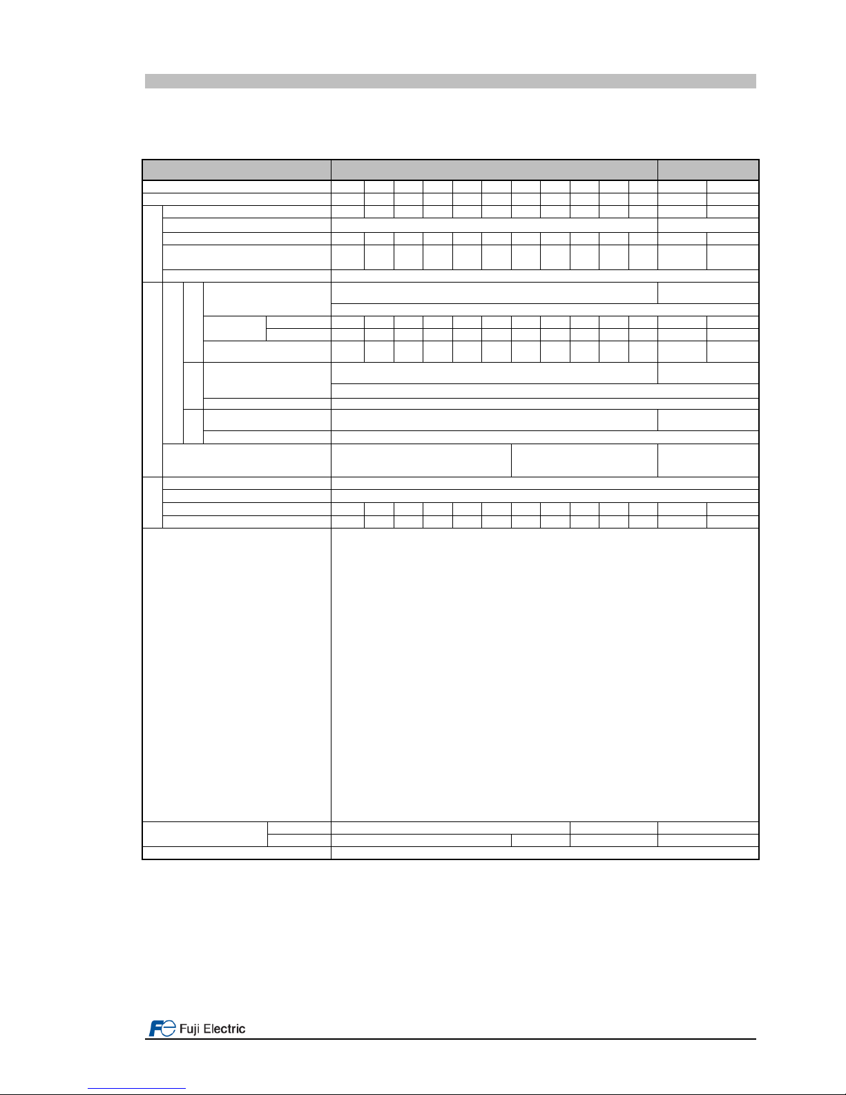
Table 3.1. FRENIC-Lift LM2A General specifications
Item 3-phase 400 V 1-phase 200 V
Type FRN___LM2A-□E □:4/7 0006 0010 0015 0019 0025 0032 0039 0045 0060 0075 0091 0011 0018
Nominal applied motor [kW] 2.2 4.0 5.5 7.5 11 15 18.5 22 30 37 45 2.2 4.0
Output ratings
Rated capacity1 [kVA] 4.6 7.6 11 14 18 24 29 34 45 57 69 4.1 6.8
Rated voltage2 [V] 3-phase 480 to 480 VAC 3-ph 200 to 240 VAC
Rated current3 [A] 6.1 10.0 15.0 18.5 24.5 32.0 39.0 45.0 60.0 75.0 91.0 11.0 18.0
Overload capacity [A]
(Permissible overload time)
11.0
(3)
18.0
(3)
27.0
(3)
37.0
(3)
49.0
(3)
64.0
(3)
78.0
(3)
90.0
(3)
120
(3)
150
(3)
182
(3)
22.0
(3)
36.0
(3)
Rated frequency [Hz] 50, 60 Hz
Input ratings
Main power supply
Normal
Phases, voltage, frequency
3-ph 380 to 480 VAC, 50/60 Hz
1-ph 200 to 240 VAC,
50/60 Hz
Variations: Voltage: +10 to -15% (Voltage unbalance: 2% or less4), Frequency: +5 to -5%
Rated
current3 [A]
With DCR 4.5 7.5 10.6 14.4 21.1 28.8 35.5 42.2 57.0 68.5 83.2 17.5 33.0
Without DCR 8.2 13.0 17.3 23.2 33.0 43.8 52.3 60.6 77.9 94.3 114 24.0 41.0
Required power supply
capacity (with DCR) [kVA]
3.2 5.2 7.4 10.0 15.0 20.0 25.0 30.0 40.0 48.0 58.0 3.5 6.1
UPS
Input power for driving
phases, voltage, frequency
1-ph 220 to 480 VAC, 50/60 Hz
1-ph 200 to 240 VAC,
50/60 Hz
Variations: Voltage: +10 to -10%, Frequency: +5 to -5%
Operation time [s] 180
Battery
Input power for driving
voltage
48 VDC 36 VDC
Operation time [s] 180
Aux. control power voltage 24 VDC (22 to 32 VDC), max. 40 W 1-ph 220 to 480 VAC, 50/60 Hz8
24 VDC (22 to
32VDC),
max. 40 W
Braking
Braking time7 [s] 60
Braking duty-cycle (%ED)7 [%] 50
Rated regenerative power7 [kW] 1.8 3.2 4.4 6.0 8.8 12.0 14.8 17.6 24.0 29.6 36.0 1.8 3.2
Minimum resistance6 [Ω]
160 96 47 47 24 24 16 16 10 8.5 8 33 20
Conformity standard
- Lift Directive (95/16/EC)
- Replacement of two motor contactors: interrupting the current to the motor (to stop the machine),
as required by EN 81-1:1998+A3:2009 12.7.3 a), EN 81-2:1998+A3:2009 12.4.1 a) and EN 8120:2014 5.9.2.5.4 d),
5.9.3.4.1 d).
- Brake monitoring for UCM:EN 81-1:1998+A3:2009 9.11.3 and EN 81-20:2014 5.6.7.3
- Travel direction change counter for lifts with belt or coated ropes
- Machinery Directive
- EN ISO13849-1: PL-e
- EN60204-1: stop category 0
- EN61800-5-2: STO SIL3
- EN62061: SIL3
- Low Voltage Directive
- EN61800-5-1: Over voltage category 3
- EMC Directive
- EN12015, EN12016, EN 61800-3 +A1, EN 61326-3-1
(Emission) Built-in EMC filter type: Category 2 (0025 (11kW) or lower) / Category 3 (0032 (15kW) or
higher)
(Immunity) 2nd Env.
- Canadian and U.S. standards
- Can/CSA C22.2 No.14-13: Industrial Control Equipment
- CSA C22.2 No.274-13: Adjustable speed drives
- UL 508 C (3rd Edition): Power Conversion Equipment
- According to CSA B44.1-11/ASME A17.5-2014: Elevator and escalator electrical equipment
Enclosure
(IEC60529)
Main body IP20 IP00 IP20
Heat sink IP54 IP20 IP00 IP54
Cooling method Fan cooling
*1) Rated capacity is calculated by regarding the output rated voltage as 440 VAC.
*2) Output voltage cannot exceed the power supply voltage.
*3) These values correspond to the following conditions: carrier frequency is 10 kHz (2 phase modulation) and ambient temperature is 45°C. Select the
inverter capacity such that the square average current during operation is not higher than the 80% of the rated current of the inverter.
*4) Voltage unbalance [%] = (Max.voltage [V] - Min.voltage [V])/ Three-phase average voltage [V] x 6 (IEC61800-3). Just for 3ph 400 VAC input supply
case.
*5) The power supply capacity is 500kVA (ten times the inverter capacity when the inverter capacity exceeds 50kVA), and the value of the power
supply impedance is %X=5%.
*6) The admissible error of minimum resistance is ±5%.
*7) Braking time and duty cycle (%ED) are defined by cycle operation at the rated regenerative power.
*8) Variations (Voltage: +10 to -10%, Frequency: +5 to -5%)
Page 8 of 35 Fuji Electric Europe GmbH
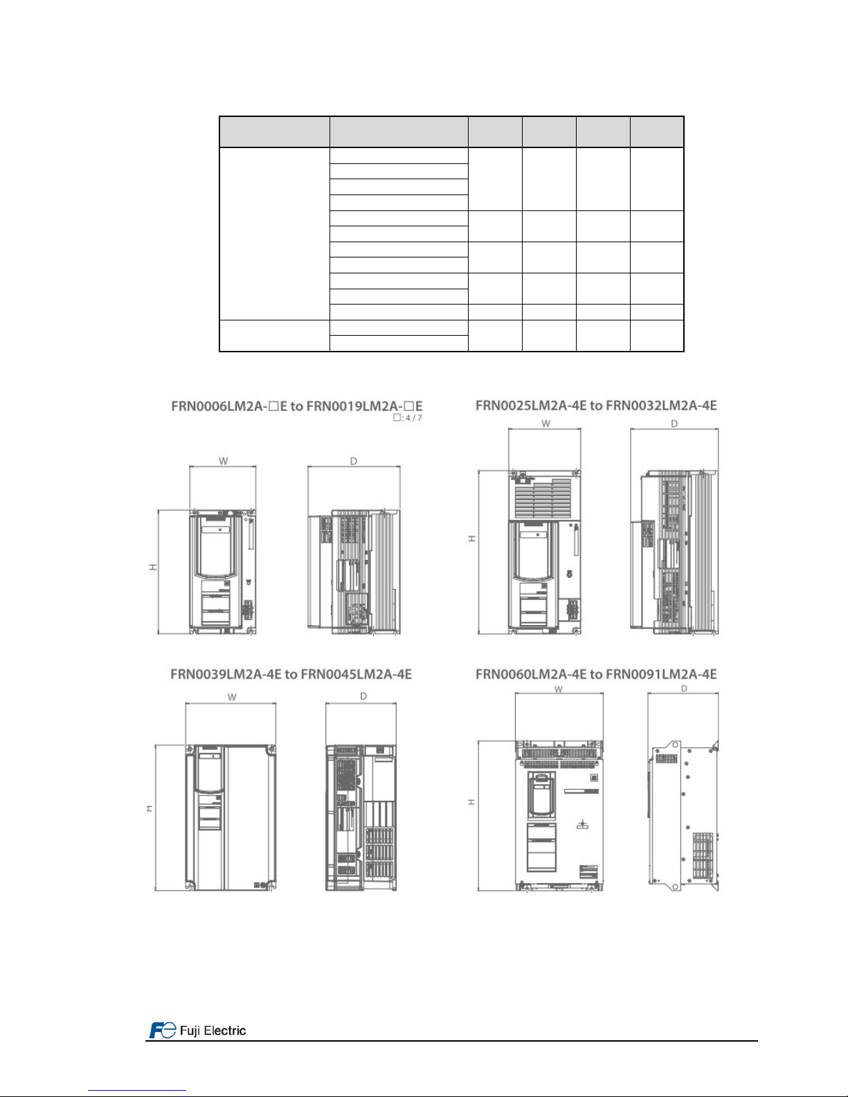
3.2 External dimensions
Table 3.2. External dimensions and frame definition
Power Supply
voltage
Type Frame
W
(mm)
H
(mm)
D
(mm)
3-ph 400 VAC
FRN0006LM2A-4E
1 140,0 260,0 195,0
FRN0010LM2A-4E
FRN0015LM2A-4E
FRN0019LM2A-4E
FRN0025LM2A-4E
2 160,0 360,0 195,0
FRN0032LM2A-4E
FRN0039LM2A-4E
3 250,0 400,0 195,0
FRN0045LM2A-4E
FRN0060LM2A-4E
4 326,2 550,0 261,3
FRN0075LM2A-4E
FRN0091LM2A-4E 5 361,2 615,0 276,3
1-ph 200 VAC
FRN0011LM2A-7E
1 140,0 260,0 195,0
FRN0018LM2A-7E
Frame 1 and frame 2 can be called as well from now on Book type.

Page 9 of 35 Fuji Electric Europe GmbH
4. Removal and attachment of front cover
In order to remove properly front cover in each frame, please follow the procedure below shown in each figure. In the
following description, it is assumed that the inverter has already been installed.
Figure 4.1: Removing front cover step by step (Frame 1 & 2 – Book type)
Figure 4.2: Removing front cover step by step (Frame 3)
Figure 4.3: Removing front cover step by step (Frame 4 & 5)
Page 10 of 35 Fuji Electric Europe GmbH
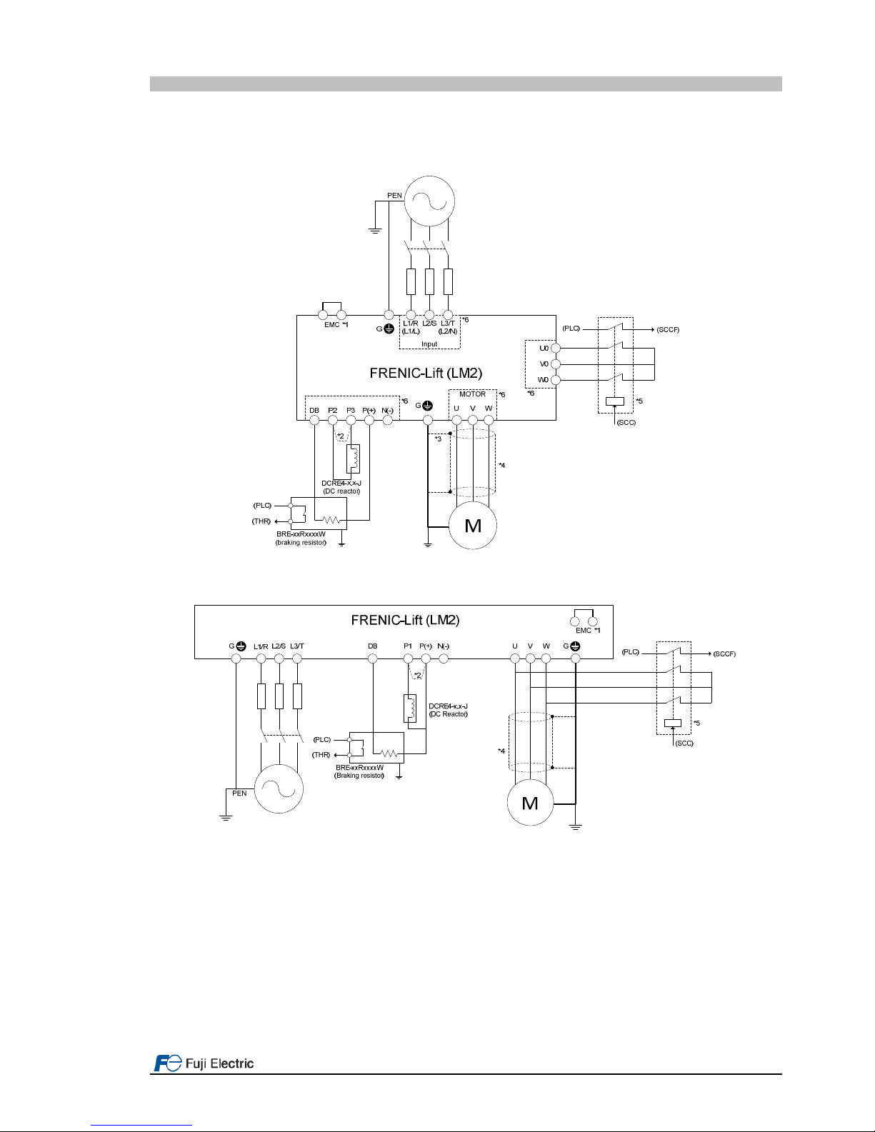
5. Connections
5.1 Power connection
In LM2A two frames typologies can be identified. One is book type frame, the one which includes frame 1 and 2. The
other one is standard frame and includes frames from 3 to 5. The different connection types are shown in figures 5.1
and 5.2.
Figure 5.1. Power terminals connection in book type frames (frame 1-2).
Figure 5.2. Power terminals connection in frames 3~5.
Note *1: Jumper to connect/disconnect internal EMC filter. In case of book type it is a metal plate placed on the EMC
terminal. In case of other frames it is a wire jumper placed inside (front cover has to be removed).
Note *2: DC Reactor terminals:
- Frames 1 and 2: In case of NOT installing DC Reactor wire a jumper between terminals P2 and P3.
- Frames 3-5: In case of installing DC Reactor remove metal plate jumper between P1 and P(+).
Note *3: Use the metal plates placed on removable terminals to connect the shield by means of metal cable ties for
example.
Note *4: In case of not installing the two MC between motor and inverter, please follow the procedure explained in
“AN-Lift2-0001” document.
Note *5: External MC for PMS motor phases short-circuit is an optional function.
Note *6: Removable terminals.
Page 11 of 35 Fuji Electric Europe GmbH
All the power terminals, independently of frame, even don’t appear on figure 5.1 and 5.2 are listed in table 5.1.
Table 5.1. Power terminals description
Terminal label Description of the power terminals
L1/R, L2/S, L3/T
(L1/L, L2/N)
3-phase supply input from mains supply.
(1-phase supply input from mains supply).
U, V, W 3-phase motor connection for induction or permanent magnet synchronous motors.
U0, V0, W0 PMS motor short circuit phases terminals (Book type frames only).
DC
Reactor
P2, P3 DC Reactor connection (book type frames only).
P1, P(+) DC Reactor connection (frames 3-5 only).
24V+, 24V-
Input power terminals for 24 VDC. These terminals have to be used in case of rescue
operation by means of batteries to supply control circuit.(Book type frame only).
R0, T0
Input power terminals for 220 VAC. These terminals have to be used in case of rescue
operation by means of batteries to supply control circuit. (Frames 3-5 only).
DB , P(+) Connection of external braking resistor.
EMC Jumper to connect/disconnect internal EMC filter.
G
Terminals for the connection of the inverter enclosure with the protecting earth.
Book type frames: 3 terminals available. Frames 3~5: 2 terminals available.
Please connect the screen in both motor and inverter sides. Ensure that the screen is continued also through the
main contactors (if used).
It is recommended to use braking resistors with thermal switch in order to protect the system from failures.
Additionally, inverter has a software function to electronically protect the system (For additional information please
check parameters F50 to F52).
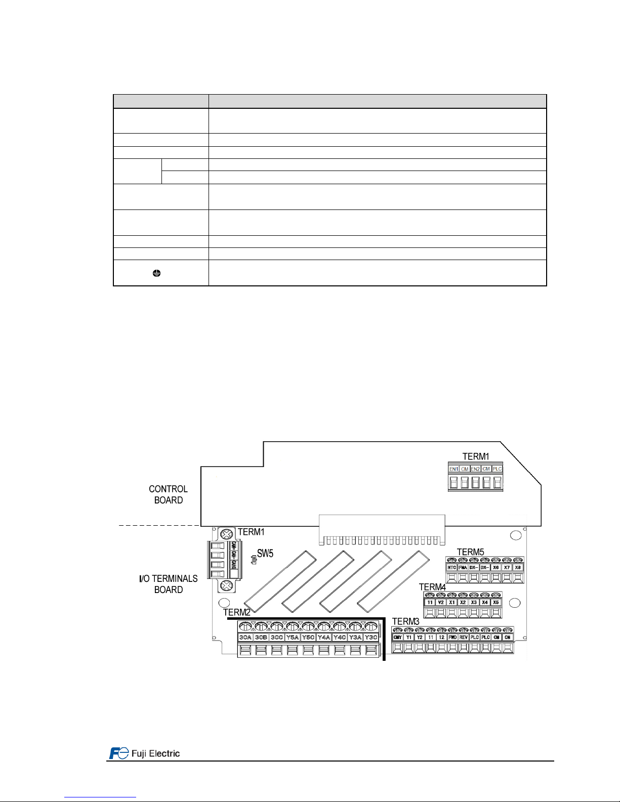
5.2 Control signals connection
In figure 5.3 all control terminals included in the electronic boards are shown. Electronic boards are divided in control
board (fixed) and I/O terminals board (removable). I/O terminals board can be easily removed from control board. EN
circuit terminals have their own connector which can be removed as well. For additional information about wiring and
terminals function refer to below sub chapters.
Figure 5.3. Control board and I/O terminals board terminals
All the examples below are based on FRENIC-Lift (LM2A) default setting. For other functions please refer to FRENICLift RM document.
 Loading...