

Fuji Electric FRENIC-HVAC Series Instruction Manual
Instruction Manual
UL/NEMA Type 1 & Type 12
FRENIC-HVAC
Combination VFD
Fuji Electric Corp. of America FECA-IN-117 / 120715
Information subject to change without notice.
Safety Precautions
Read this manual thoroughly before proceeding with installation, connections (wiring), or
maintenance and inspection. Ensure you have sound knowledge of the device and
familiarize yourself with all safety information and precautions before proceeding to
operate the drive. Refer to the FRENIC-HVAC
1707c-JE) for further safety information.
Safety precautions are classified into the following two categories in this manual.
WARNING
Failure to heed the information indicated by this symbol may lead to dangerous
conditions, possibly resulting in death or serious bodily injuries.
CAUTION
Failure to heed the information indicated by this symbol may lead to dangerous
conditions, possibly resulting in minor or light bodily injuries and/or substantial property
damage.
drive Instruction Manual (INR-SI47-
Page 2 of 37

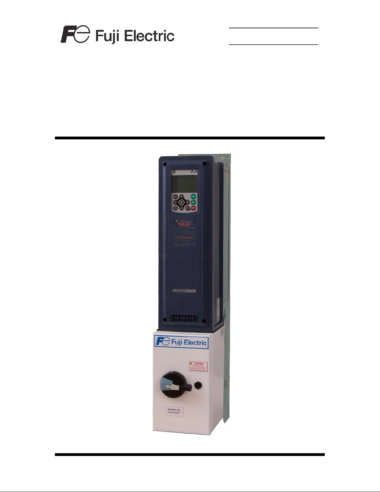
FRENIC-HVAC Combination VFD Overview
The FRENIC-HVAC Combination VFD is a packaged drive solution in a UL Type 1 or
Type 12 enclosure designed for indoor HVAC applications.
Features
• UL/NEMA Type 1 or Type 12 enclosure – “slim-type”
design
• Non-fusible input disconnect with padlockable through-the-door operator handle
mechanically interlocked with the enclosure cover/door (motor branch circuit
protection required and to be provided by others), also available is an optional input
circuit breaker with padlockable through-the-door operator handle mechanically
interlocked with the enclosure cover/door
• DC link reactor integra l for im pr oved power factor and
harmonic mitigation up to 60 HP at 208/230V and 125 HP
at 460 & 575V. External mounted within the enclosure for
larger sizes.
• Integral EMC filter compliant with IEC/EN61800-3-12
• VFD mounted keypad with backlit LCD for drive set-up,
troubleshooting, local operation control, maintenance
indication, and operational indication. Keypad displays
engineering units for easy-to-understand information.
• Keypad functions as a copy unit
• 0 to 10Vdc or 0/4 to 20mA customer supplied analog input
for speed reference
• 0 to 10Vdc or 0/4 to 20mA analog output for indication
(programmable)
• Run, Enable, and Fireman Override inputs
• Optional damper control output contacts
• Drive Run and Fault status output contacts
• Real Time Clock (RTC) function with alarm history for the
last 10 alarms
• Enhanced automatic energy savings, reduces power
consumption of both the motor and VFD
• Power consumption data available via VFD keypad
• Built-in PID control with sleep function & auto-tuning
• “Catch-a-spinning motor” functionality available
• Built-in communications user selectable between Modbus
RTU, Metasys
communication drive options including; LonWorks
EtherNet [including Modbus/TCP & BACnet/IP]
• UL Listed assembly per UL-508A
®
N2, or BACnet, with additional
®
and
Page 3 of 37
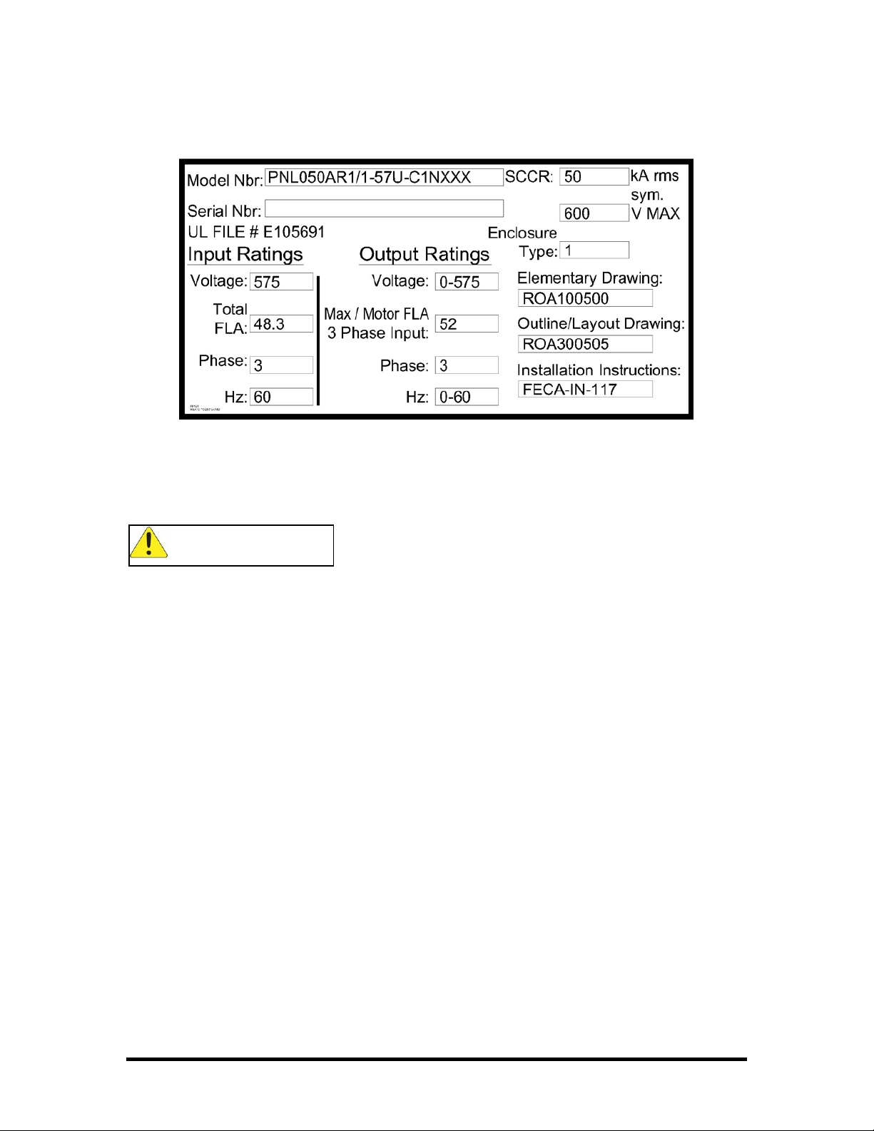
Panel Identification
Each FRENIC-HVAC Combination VFD has a nameplate label, like the example
pictured above, which contains important information about the panel. This label is
located on the inside of the hinged door or cover of the enclosure.
CAUTION
• Refer to the nameplate label to determine the panel input voltage and current
requirements prior to installation and wiring.
• Refer to the nameplate label for the correct wiring diagram (Elementary Drawing).
• Sizing of field wiring conductors should be based upon the current ratings listed on
the nameplate label.
Page 4 of 37

Installation
CAUTION
The FRENIC-HVAC Combination VFD should be located:
• Away from flammable or combustible liquids, gases, and other materials
• Away from sources of severe dust, metal shavings, or other particulate
material
• Away from corrosive liq uid s , spray, or mist
• Away from sources of h eat
• Where the ambient temperature will remain between -10°C (14°F) and 40°C
(104°F)
• Where the elevation is 3300ft or lower, above this level requires derating the
current
Wall-mount panels must be mounted to a surface that is capable of supporting the
weight of the panel.
Refer to the Outline/Layout drawing that shipped with the panel for required clearances.
Routing of field wiring should be planned in coordination with choosing a mounting
location.
Disconnect – Motor branch circuit protection to be provided by customer/others per table
on next page.
Page 5 of 37

Motor Branch Circuit Protection
208/230VAC, 60Hz, 3PH
1
10A - Class J Time-Delay Fuses
2
10A - Class J Time-Delay Fuses
3
15A - Class J Time-Delay Fuses
5
25A - Class J Time-Delay Fuses
7.5
30A - Class J Time-Delay Fuses
10
50A - Class J Time-Delay Fuses
15
70A - Class J Time-Delay Fuses
20
100A - Class J Time-Delay Fuses
25
100A - Class J Time-Delay Fuses
460VAC, 60Hz, 3PH
1
3A - Class J Time-Delay Fuses
2
6A - Class J Time-Delay Fuses
3
10A - Class J Time-Delay Fuses
5
15A - Class J Time-Delay Fuses
7.5
20A - Class J Time-Delay Fuses
10
25A - Class J Time-Delay Fuses
15
30A - Class J Time-Delay Fuses
20
50A - Class J Time-Delay Fuses
25
60A - Class J Time-Delay Fuses
30
70A - Class J Time-Delay Fuses
40
100A - Class J Time-Delay Fuses
50
100A - Class J Time-Delay Fuses
575VAC, 60Hz, 3PH
1
3A - Class J Time-Delay Fuses
2
6A - Class J Time-Delay Fuses
3
6A - Class J Time-Delay Fuses
5
10A - Class J Time-Delay Fuses
7.5
15A - Class J Time-Delay Fuses
10
20A - Class J Time-Delay Fuses
15
25A - Class J Time-Delay Fuses
20
30A - Class J Time-Delay Fuses
25
40A - Class J Time-Delay Fuses
30
50A - Class J Time-Delay Fuses
40
70A - Class J Time-Delay Fuses
50
100A - Class J Time-Delay Fuses
Hp
Rating
Additional Motor Branch Circuit
Protection Maximum Amp Rating
& Type Required
Page 6 of 37
Wiring Overview
The FRENIC-HVAC Combinat ion VFD must be connected to an input power source, a
motor (output power), ground, and control may be local or by using remote devices such
as switches, potentiometers, etc….
WARNING
• Wiring should be performed by a qualified electrician using standard practices as
specified by local and national codes.
• Alway s make sure the input power source is OFF before connecting or disconnecting
any power input, output, or control wiring.
• Ground the panel, as specified by local and national codes, using the provided
grounding lugs.
• Make sure that the input power source (phases, voltage, and current capacity)
matches the requirements of the panel as stated on the nameplate.
• Never connect line voltage to the drive output terminals (U, V, and W).
• IF not using the provided conduit holes, then when making holes for conduit fittings,
be sure to cover the drive and other components to protect them from metal
shavings.
CAUTION
• All field wiring should be copper with a minimum insulation rating of 75°C.
• Sizing of field wiring conductors should be based upon the current ratings listed on
the nameplate label, in accordance with local and national codes.
Refer to the Elementary diagram that shipped with this panel and the torque table in this
Instruction Manual.
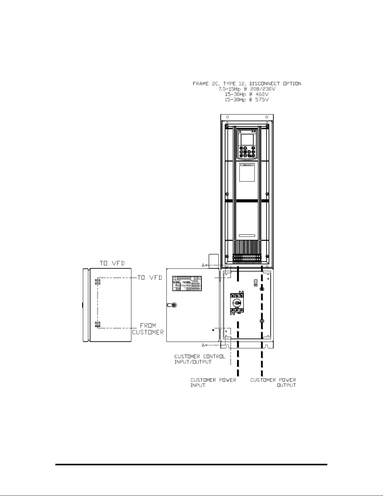
Refer to the diagrams on the following pages for general component layout and for
general routing of power input, power output (motor connections), and control wiring for
your panel. Power input wiring should be routed away from power output wiring, and
both should enter the panel from separate conduit. Control wiring should be routed away
from power wiring, and should enter the panel from separate conduit.
Refer to the following section Control Wiring for descriptions of the control connections.
Page 7 of 37
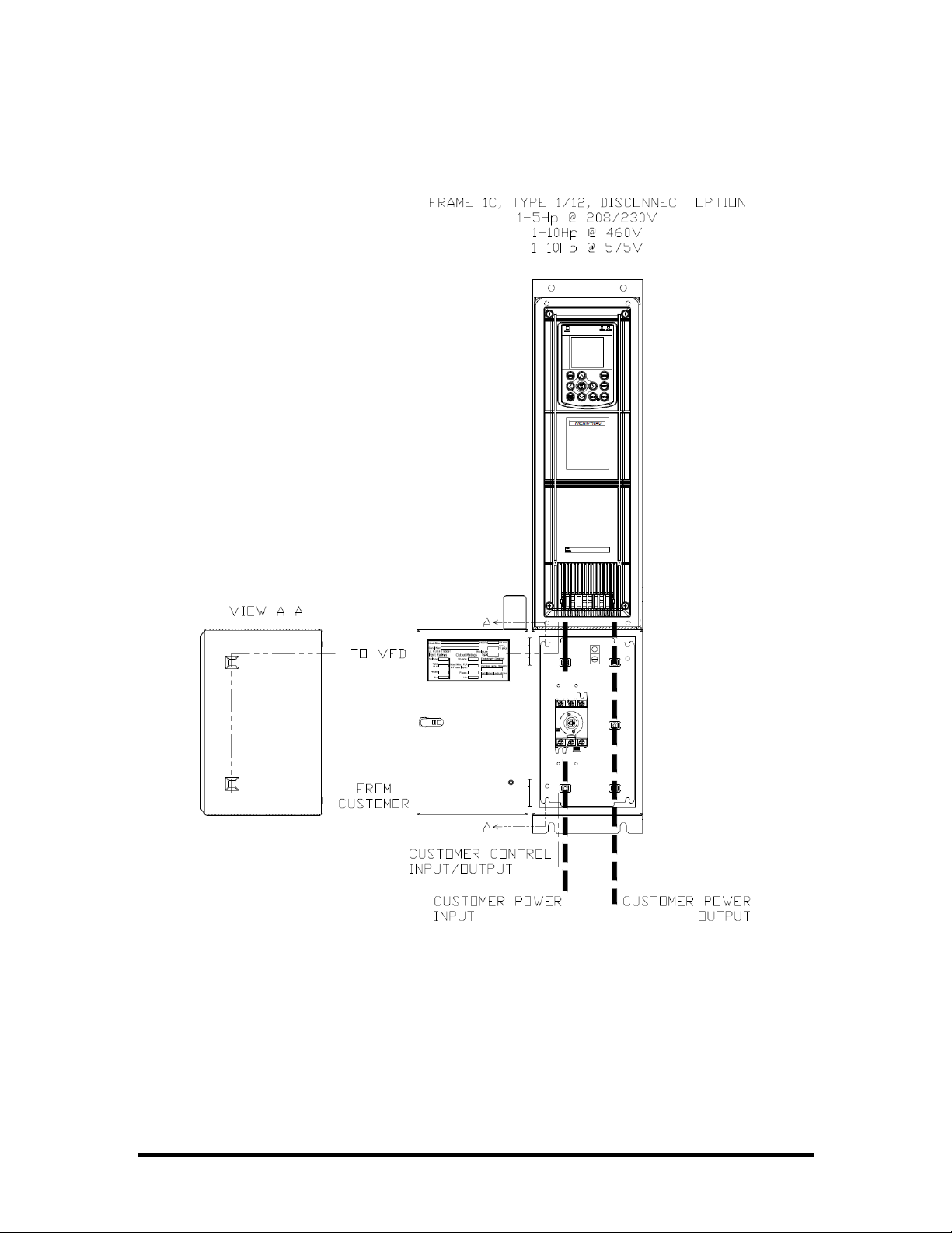
Wiring Overview (cont’d)
UL/NEMA Type 1 & 12 (Typical Wire Routing)
Page 8 of 37
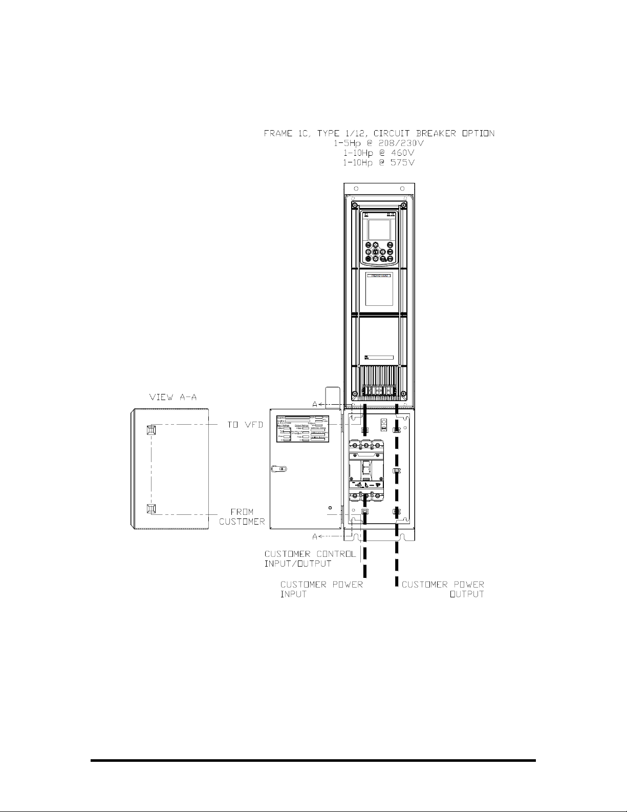
Wiring Overview (cont’d)
UL/NEMA Type 1 & 12 (Typical Wire Routing)
Page 9 of 37
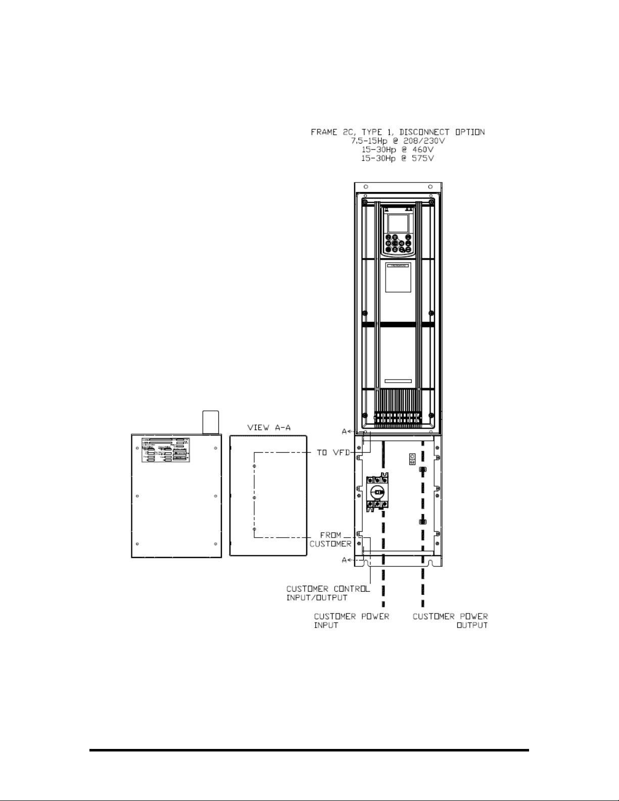
Wiring Overview (cont’d)
UL/NEMA Type 1 (Typical Wire Routing)
Page 10 of 37
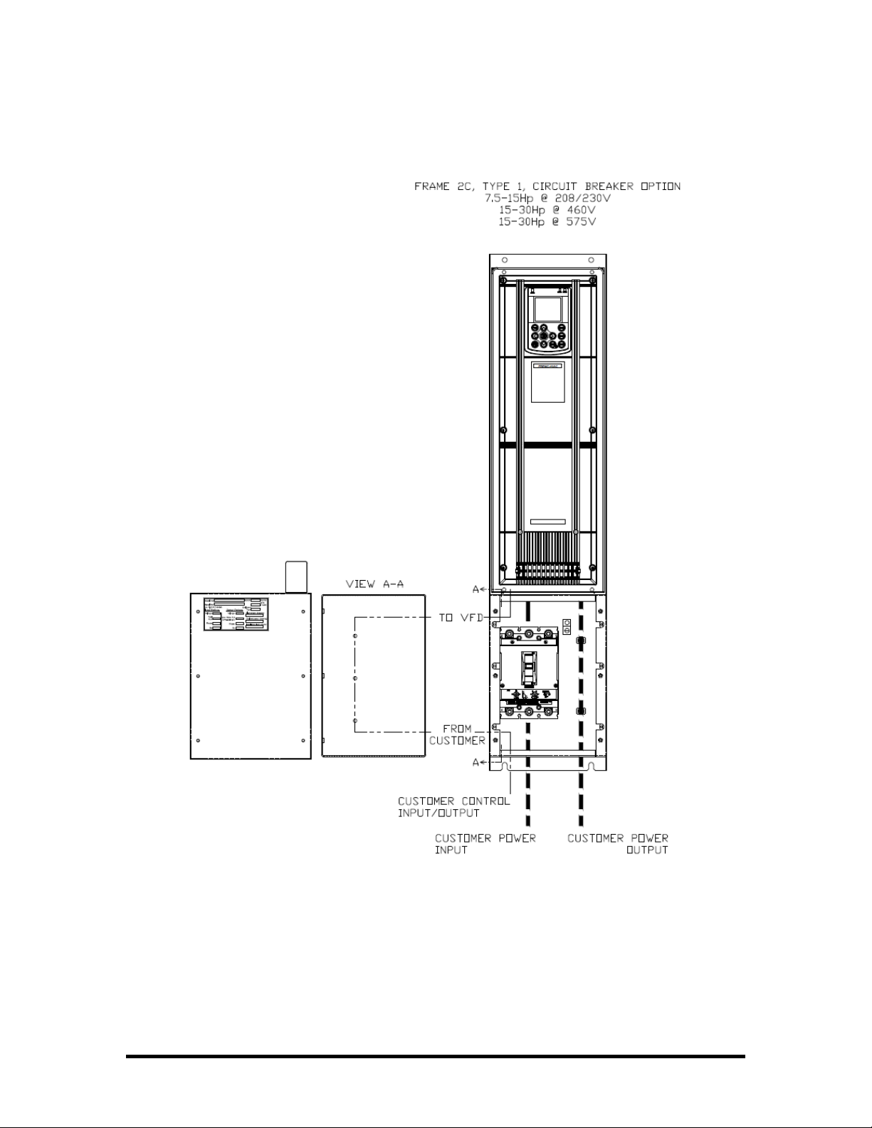
Wiring Overview (cont’d)
UL/NEMA Type 1 (Typical Wire Routing)
Page 11 of 37
Wiring Overview (cont’d)
UL/NEMA Type 12 (Typical Wire Routing)
Page 12 of 37
 Loading...