

Page 1
24A7-E-0069d
Page 2

Page 3

User's Manual
Page 4

Copyright © 2012-2016 Fuji Electric Corp. of America
All rights reserved.
No part of this publication may be reproduced or copied without prior written permission from Fuji Electric
Corp. of America.
All products and company names mentioned in this manual are trademarks or registered trademarks of their
respective holders.
The information contained herein is subject to change without prior notice for improvement.
Page 5

Preface
Catalog
Instruction Manual
RS
Communication
User's Manual
This manual provides all the information on the FRENIC-HVAC series of inverters including its operating
procedure, operation modes, and selection of peripheral equipment. Carefully read this manual for proper
use. Incorrect handling of the inverter may prevent the inverter and/or related equipment from operating
correctly, shorten their lives, or cause problems.
The table below lists the other materials related to the use of the FRENIC-HVAC. Read them in conjunction
with this manual as necessary.
Name Material No. Description
24A1-E-0068
INR-SI47-1707-JE
-485
24A7-E-0021
Product scope, features, specifications, external
drawings, and options of the product
Acceptance inspection, mounting & wiring of the
inverter, operation using the keypad, running the motor
for a test, troubleshooting, and maintenance and
inspection
Overview of functions implemented by using
FRENIC-HVA C RS-485 communications facility, its
communications specifications, Modbus RTU/Fuji
general-purpose inverter protocol and functions, and
related data formats
The materials are subject to change without notice. Be sure to obtain the latest editions for use.
The latest editions can be downloaded from our Web side at:
http://www.americas.fujielectric.com/components/drives-inverters
i
Page 6
Safety precautions
machinery related to nuclear power control, aerospace uses, medical uses or transportation. When the
Read this manual and the FRENIC-HVAC Instruction Manual (that comes with the product) thoroughly
before proceeding with installation, connections (wiring), operation, or maintenance and inspection. Ensure
you have sound knowledge of the product and familiarize yourself with all safety information and
precautions before proceeding to operate the inverter.
Safety precautions are classified into the following two categories in this manual.
Failure to heed the information indicated by this symbol may lead to
dangerous conditions, possibly resulting in death or serious bodily injuries.
Failure to heed the information indicated by this symbol may lead to
dangerous conditions, possibly resulting in minor or light bodily injuries
and/or substantial property damage.
Failure to heed the information contained under the CAUTION title can also result in serious consequences.
These safety precautions are of utmost importance and must be observed at all times.
This product is not designed for use in appliances and machinery on which lives depend. Consult your Fuji
Electric representative before considering the FRENIC-HVAC series of inverters for equipment and
product is to be used with any machinery or equipment on which lives depend or with machinery or
equipment which could cause serious loss or damage should this product malfunction or fail, ensure that
appropriate safety devices and/or equipment are installed.
ii
Page 7

How this manual is organized
This manual contains Chapters 1 through 11 and Appendices.
Chapter 1 ABOUT FRENIC-HVAC
This chapter describes the features and control system of the FRENIC-HVAC series and the recommended
configuration for the inverter and peripheral equipment.
Chapter 2 SPECIFICATIONS
This chapter describes specifications of the output ratings, control system, and terminal functions for the
FRENIC-HVAC series of inverters. It also provides descriptions of the operating and storage environment,
product warranty, precautions for use, external dimensions, examples of basic connection diagrams, and
details of the protective functions.
Chapter 3 SELECTING OPTIMAL MOTOR AND INVERTER CAPACITIES
This chapter provides you with information about the inverter output torque characteristics, selection
procedure, and equations for calculating capacities to help you select optimal motor and inverter models.
Chapter 4 SELECTING PERIPHERAL EQUIPMENT
This chapter describes how to use a range of peripheral equipment and options, FRENIC-HVAC's
configuration with them, and requirements and precautions for selecting wires and crimp terminals.
Chapter 5 PREPARATION AND TEST RUN
This chapter details the operating environment, storage environment, installation, wiring, basic connection
examples, names and functions of the keypad components, operation using the keypad, and test run
procedure.
Chapter 6 FUNCTION CODES
This chapter contains overview tables of 12 groups of function codes available for the FRENIC-HVAC series
of inverters, function code index by purpose, and details of function codes.
Chapter 7 BLOCK DIAGRAMS FOR CONTROL LOGIC
This chapter provides the main block diagrams for the control logic of the FRENIC-H VA C series of
inverters.
Chapter 8 RUNNING THROUGH RS-485 COMMUNICATION
This chapter describes an overview of inverter operation through the RS-485 communications facility. Refer
to the RS-485 Communication User's Manual for details.
Chapter 9 TROUBLESHOOTING
This chapter describes troubleshooting procedures to be followed when the inverter malfunctions or detects
an alarm or a light alarm condition. In this chapter, first check whether any alarm code or the "light alarm"
indication (L-AL) is displayed or not, and then proceed to the troubleshooting items.
Chapter 10 MAINTENANCE AND INSPECTION
This chapter provides the instructions on how to perform daily and periodic inspections in order to avoid
trouble and keep reliable operation of the inverter for a long time.
iii
Page 8

Chapter 11 CONFORMITY WITH STANDARDS
This icon indicates information which, if not heeded, can result in the inverter not operating to
full efficiency, as well as information concerning incorrect operations and settings which can
result in accidents.
This icon indicates information that can prove handy when performing certain settings or
operations.
This icon indicates a reference to more detailed information.
This chapter sets forth the conformity with overseas standards.
Appendices
Icons
The following icons are used throughout this manual.
iv
Page 9

CONTENTS
Chapter 1 About FRENIC-HVA C
1.1 Features ..................................................................................................................................................... 1-1
1.2 Inspection of goods and product appearance .................................................................................... 1-13
1.2.1 Inspection of goods ........................................................................................................................ 1-13
1.2.2 Product appearance ....................................................................................................................... 1-15
Chapter 2 SPECIFICATIONS
2.1 Standard Model FRENIC-HVAC .............................................................................................................. 2-1
2.1.1 Three-phase 230 V class series (USA models) .................................................................................... 2-1
2.1.2 Three-phase 460 V class series (USA models) ................................................................................... 2-3
2.1.3 Three-phase 575 V class series (USA models) ................................................................................... 2-6
2.2 Common Specifications .............................................................................................................................. 2-9
2.3 Terminal Specifications ............................................................................................................................. 2-16
2.3.1 Terminal functions ............................................................................................................................ 2-16
2.3.2 Setting up the slide switches ............................................................................................................. 2-26
2.3.3 Screw specifications and recommended wire sizes ........................................................................... 2-28
2.3.3.1 Main circuit terminals ............................................................................................................... 2-28
2.3.3.2 Control circuit terminals (Common to all inverter types) ......................................................... 2-35
2.4 Conduits .................................................................................................................................................... 2- 36
2.4.1 Conduits ............................................................................................................................................ 2-36
2.5 Leakage Current of the EMC Filter........................................................................................................... 2-39
2.6 Derating of Rated Output Current ............................................................................................................. 2-42
2.7 Operating Environment and Storage Environment ................................................................................... 2-44
2.7.1 Operating environment ...................................................................................................................... 2-44
2.7.2 Storage environment ......................................................................................................................... 2-45
2.7.2.1 Temporary storage ..................................................................................................................... 2-45
2.7.2.2 Long-term storage ..................................................................................................................... 2-45
2.8 Precautions for Using Inverters ................................................................................................................. 2-46
2.8.1 Precautions in introducing inverters .................................................................................................. 2-46
2.8.2 Precautions in running inverters ........................................................................................................ 2-50
2.8.3 Precautions in using special motors .................................................................................................. 2-50
2.9 External Dimensions ................................................................................................................................. 2- 51
2.9.1 Standard models ................................................................................................................................ 2- 51
2.9.2 Keypad .............................................................................................................................................. 2-64
2.10 Connection Diagrams ................................................................................................................................ 2-65
Chapter 3 SELECTING OPTIMAL MOTOR AND INVERTER CAPACITIES
3.1 Selecting Motors and Inverters ................................................................................................................... 3-1
3.1.1 Motor output torque characteristics ..................................................................................................... 3-1
3.1.2 Selection procedure ............................................................................................................................. 3-3
3.1.3 Equations for selections ...................................................................................................................... 3-6
3.1.3.1 Load torque during constant speed running ................................................................................ 3-6
3.1.3.2 Calculation of acceleration/deceleration time ............................................................................. 3-7
3.1.3.3 Heat energy calculation of braking resistor ............................................................................... 3-10
Chapter 4 SELECTING Peripheral EQUIPMENT
4.1 Configuring the FRENIC-HVAC ................................................................................................................ 4-1
4.2 Currents flowing across the inverter terminals ............................................................................................ 4-2
4.3 Peripheral Equipment .................................................................................................................................. 4-5
v
Page 10

4.3.1 Molded case circuit breaker (MCCB), residual-current-operated protective device (RCD)/
earth leakage circuit breaker (ELCB) and magnetic contactor (MC) .................................................. 4-5
4.3.2 Surge killers for L-load ..................................................................................................................... 4-10
4.3.3 Arresters ............................................................................................................................................ 4-11
4.3.4 Surge absorbers ................................................................................................................................. 4-12
4.4 Options ...................................................................................................................................................... 4- 13
4.4.1 Selecting peripheral equipment options ............................................................................................ 4-13
4.4.1.1 Power regenerative PWM converters, RHC series .................................................................... 4-13
4.4.1.2 AC reactors (ACRs) .................................................................................................................. 4-36
4.4.1.3 DC reactors (DCRs) (Built-in or bundled as standard) ............................................................. 4-41
4.4.1.4 Surge suppression unit (SSU) .................................................................................................... 4-43
4.4.1.5 Output circuit filters (OFLs) ...................................................................................................... 4-44
4.4.1.6 Zero-phase reactors for reducing radio noise (ACLs) ............................................................... 4-48
4.4.2 Selecting options for operation and communication ......................................................................... 4-49
4.4.2.1 External frequency command potentiometer ............................................................................. 4-49
4.4.2.2 Extension cable for remote operation ........................................................................................ 4-50
4.4.2.3 Frequency meters ...................................................................................................................... 4-50
4.4.2.4 Inverter support loader software ................................................................................................ 4-51
4.4.3 Selecting Option Cards ..................................................................................................................... 4-52
4.4.3.1 List of option cards, connection ports, and applicable ROM versions ...................................... 4-52
4.4.3.2 Relay output interface card (OPC-RY) ...................................................................................... 4-53
4.4.3.3 Relay output interface card (OPC-RY2) .................................................................................... 4-55
4.4.3.4 Analog interface card (OPC-AIO)............................................................................................. 4-57
4.4.3.5 Analog current output (2 ch) interface card (OPC-AO) ............................................................ 4-61
4.4.3.6 Resistance temperature detector input card (OPC-PT) .............................................................. 4-63
4.4.3.7 CC-Link communications card (OPC-CCL) ............................................................................. 4-66
4.4.3.8 PROFIBUS-DP communications card (OPC-PDP2) ................................................................ 4-68
4.4.3.9 DeviceNet communications card (OPC-DEV) .......................................................................... 4-71
4.4.3.10 CANopen communications card (OPC-COP) ........................................................................... 4-74
4.4.3.11 LONWORKS communications card (OPC-LNW) ................................................................... 4-76
4.4.3.12 Ethernet communications card (OPC-ETH) .............................................................................. 4-77
4.5 Backup Battery .......................................................................................................................................... 4-79
4.5.1 Outline ............................................................................................................................................... 4-79
4.5.2 Loading the battery ........................................................................................................................... 4-80
4.5.3 Battery replacement procedure .......................................................................................................... 4-82
4.5.4 About air transport of batteries .......................................................................................................... 4-82
Chapter 5 PREPARATION AND TEST RUN
5.1 Mounting and Wiring the Inverter ............................................................................................................... 5-1
5.1.1 Installing the inverter .......................................................................................................................... 5-1
5.1.2 Wiring ................................................................................................................................................. 5-4
5.1.2.1 Removing and mounting the front cover and the wiring plate .................................................... 5-4
5.1.2.2 Input ferrite core diameter ........................................................................................................... 5-7
5.1.3 Screw specifications and recommended wire sizes ............................................................................. 5-7
5.1.3.1 Main circuit terminals ................................................................................................................. 5-7
5.1.3.2 Control circuit terminals (Common to all inverter types) ........................................................... 5-7
5.1.4 Conduits .............................................................................................................................................. 5-7
5.1.5 Wiring precautions .............................................................................................................................. 5-8
5.1.6 Wiring of main circuit terminals and grounding terminals.................................................................. 5-9
5.1.7 Wiring for control circuit terminals ................................................................................................... 5-16
5.1.8 Setting up the slide switches ............................................................................................................. 5-19
5.1.9 USB port ........................................................................................................................................... 5-20
vi
Page 11

5.2 Mounting and Connecting a Keypad ......................................................................................................... 5-21
5.2.1 Parts required for connection ............................................................................................................ 5-21
5.2.2 Mounting procedure .......................................................................................................................... 5-21
5.3 Operation Using the Keypad ..................................................................................................................... 5-24
5.3.1 LCD monitor, keys and LED indicators on the keypad ..................................................................... 5-24
5.4 Overview of Operation Modes .................................................................................................................. 5-28
5.5 Running Mode .......................................................................................................................................... 5-29
5.5.1 Monitoring the running status ........................................................................................................... 5-29
5.5.2 Setting up frequency and PID commands ......................................................................................... 5-32
5.5.3 Running/stopping the motor .............................................................................................................. 5-36
5.5.4 Remote and local modes ................................................................................................................... 5-36
5.5.5 Changing from keypad operation to external signal (terminal block) operation ............................... 5-37
5.5.6 Monitoring light alarms ..................................................................................................................... 5-37
5.6 Programming Mode .................................................................................................................................. 5-38
5.6.1 Quick Setup ....................................................................................................................................... 5-40
5.6.2 Start-up .............................................................................................................................................. 5-40
5.6.2.1 Set Display Language ................................................................................................................ 5-41
5.6.2.2 Function-Specific Initialization ................................................................................................. 5-42
5.6.2.3 Date/Time Settings .................................................................................................................... 5-42
5.6.2.4 Set Display ................................................................................................................................ 5-45
5.6.3 Function Codes ................................................................................................................................. 5-46
5.6.3.1 Setting up function codes .......................................................................................................... 5-47
5.6.3.2 Confirm Data ............................................................................................................................. 5-49
5.6.3.3 Confirm Changed Function Code .............................................................................................. 5-49
5.6.3.4 Copying data ............................................................................................................................. 5-49
5.6.3.5 Set Timer Operation .................................................................................................................. 5-61
5.6.3.6 Initialize Data ............................................................................................................................ 5-64
5.6.4 Inverter Information .......................................................................................................................... 5-65
5.6.4.1 Confirm Power Level ................................................................................................................ 5-65
5.6.4.2 Confirm Operational Status ....................................................................................................... 5-66
5.6.4.3 Check Status of Input/Output Signal ......................................................................................... 5-69
5.6.4.4 View Maintenance Information ................................................................................................. 5-71
5.6.4.5 View Unit Information .............................................................................................................. 5-75
5.6.5 Alarm Information ............................................................................................................................ 5-76
5.6.5.1 Confirm Alarm History ............................................................................................................. 5-76
5.6.5.2 Confirm Light Alarm History .................................................................................................... 5-80
5.6.5.3 Retry History ............................................................................................................................. 5-80
5.6.6 User Config ....................................................................................................................................... 5-81
5.6.6.1 Quick Setup ............................................................................................................................... 5-81
5.6.6.2 Password ................................................................................................................................... 5-81
5.6.7 Tools .................................................................................................................................................. 5-85
5.6.7.1 Monitor PID Control Status ...................................................................................................... 5-85
5.6.7.2 Monitor Multiple Unit Controls ................................................................................................ 5-88
5.6.7.3 Monitor Customized Logic (CLogic) ........................................................................................ 5-91
5.6.7.4 Resonance Avoidance ................................................................................................................ 5-92
5.6.7.5 Load Factor Measurement ......................................................................................................... 5-93
5.6.7.6 Communication Debug ............................................................................................................. 5-96
5.7 Alarm Mode .............................................................................................................................................. 5-97
5.7.1 Releasing the alarm and switching to Running mode ....................................................................... 5-97
5.7.2 Displaying the alarm history ............................................................................................................. 5-97
5.7.3 Displaying the status of inverter at the time of alarm ....................................................................... 5-97
5.7.4 Test run procedure ............................................................................................................................. 5-98
vii
Page 12

5.7.5 Checking prior to powering ON ........................................................................................................ 5-99
5.7.6 Powering ON and checking............................................................................................................. 5-100
5.7.7 Selecting a desired motor drive control ........................................................................................... 5-100
5.7.8 Function code basic settings < 1 > .................................................................................................. 5-101
5.7.9 Function code basic settings and tuning < 2 > ................................................................................ 5-103
5.7.10 Running the inverter for motor operation check ............................................................................. 5-106
5.7.11 Preparation for practical operation .................................................................................................. 5-107
Chapter 6 FUNCTION CODES
6.1 Overview of Function Codes ...................................................................................................................... 6-1
6.2 Function Code Tables .................................................................................................................................. 6-2
6.3 Details of Function Codes ......................................................................................................................... 6-41
6.3.1 F codes (Fundamental functions) ...................................................................................................... 6-41
6.3.2 E codes (Extension terminal functions) ............................................................................................. 6-84
6.3.3 C codes (Control functions) ............................................................................................................ 6-125
6.3.4 P codes (Motor 1 parameters) ......................................................................................................... 6-137
6.3.5 H codes (High performance functions) ........................................................................................... 6-141
6.3.6 H1 codes (High performance functions) ......................................................................................... 6-174
6.3.7 J codes (Application functions 1) .................................................................................................... 6-181
6.3.8 J1 codes (PID control 1) .................................................................................................................. 6-182
6.3.9 J2 codes (PID control 2) .................................................................................................................. 6-215
6.3.10 J5 codes (External PID control 1) ................................................................................................... 6-217
6.3.11 J6 codes (External PID control 2, 3) ............................................................................................... 6-245
6.3.12 d codes (Application functions 2) ................................................................................................... 6-249
6.3.13 U codes (Customizable logic functions) ......................................................................................... 6-249
6.3.14 U1 codes (Customizable logic functions) ....................................................................................... 6-270
6.3.15 y codes (Link functions) .................................................................................................................. 6-275
6.3.16 T codes (Timer functions) ............................................................................................................... 6-280
6.3.17 K codes (Keypad functions) ............................................................................................................ 6-284
Chapter 7 BLOCK DIAGRAMS FOR CONTROL LOGIC
7.1 Symbols Used in Block Diagrams and their Meanings ............................................................................... 7-1
7.2 Frequency Command Block ........................................................................................................................ 7-2
7.3 Drive Command Block ............................................................................................................................... 7-4
7.4 V/f Control Block ....................................................................................................................................... 7-5
7.5 PID Process Control Block ......................................................................................................................... 7-7
7.6 External PID Process Control Block ........................................................................................................... 7-9
7.7 FM1/FM2 Output Selector ........................................................................................................................ 7-11
Chapter 8 RUNNING THROUGH RS-485 COMMUNICATION
8.1 Overview on RS-485 Communication ........................................................................................................ 8-1
8.1.1 RS-485 common specifications ........................................................................................................... 8-2
8.1.2 Terminal specifications for RS-485 communication ........................................................................... 8-3
8.1.3 Connection method ............................................................................................................................. 8-4
8.1.4 Communications support devices ........................................................................................................ 8-6
8.1.5 Noise suppression ............................................................................................................................... 8-7
8.2 Overview of FRENIC Loader ..................................................................................................................... 8-8
8.2.1 Specifications ...................................................................................................................................... 8-8
8.2.2 USB port on the inverter unit .............................................................................................................. 8-9
Chapter 9 TROUBLESHOOTING
viii
Page 13

9.1 Protective Functions .................................................................................................................................... 9-1
9.2 Before Proceeding with Troubleshooting .................................................................................................... 9-2
9.3 If an Alarm Code Appears on the Monitor .................................................................................................. 9-3
9.3.1 Alarm Codes ....................................................................................................................................... 9-3
9.3.2 If the "Light Alarm" Indication Appears ........................................................................................... 9-22
9.4 Nothing appears on the monitor ................................................................................................................ 9-24
9.4.1 Abnormal motor operation ................................................................................................................ 9-24
9.4.2 Problems with inverter settings ......................................................................................................... 9-31
9.5 If Other than an Alarm Code is Displayed ................................................................................................ 9-33
Chapter 10 MAINTENANCE AND INSPECTION
10.1 Daily Inspection ........................................................................................................................................ 10-1
10.2 Periodic Inspection .................................................................................................................................... 10-1
10.3 List of Periodic Replacement Parts ........................................................................................................... 10-3
10.3.1 Judgment on service life .................................................................................................................... 10-4
10.4 Measurement of Electrical Amounts in Main Circuit ............................................................................... 10-8
10.5 Insulation Test ........................................................................................................................................... 10-9
10.6 Cooling Fan Replacement Procedure ...................................................................................................... 10-10
Chapter 11 CONFORMITY WITH STANDARDS
11.1 Compliance with European Standards ...................................................................................................... 11-1
11.1.1 Conformity to the Low Voltage Directive in the EU ......................................................................... 11-2
11.1.2 Compliance with EMC Standards ..................................................................................................... 11-8
11.1.2.1 General ...................................................................................................................................... 11-8
11.1.2.2 Recommended installation procedure ....................................................................................... 11-8
11.1.2.3 Leakage current of the EMC filter........................................................................................... 11-10
11.1.3 Harmonic Component Regulation in the EU .................................................................................. 11-14
11.1.3.1 General .................................................................................................................................... 11-14
11.1.3.2 Compliance with IEC/EN 61000-3-2 ...................................................................................... 11-14
11.1.3.3 Compliance with IEC/EN 61000-3-12 .................................................................................... 11-14
11.2 Conformity with UL Standards and cUL-listed for Canada .................................................................... 11-15
11.2.1 General ............................................................................................................................................ 11-15
11.2.2 Conformity with UL standards and cUL-listed for Canada ............................................................. 11-15
Appendices
App. A Advantageous Use of Inverters (Notes on electrical noise) ................................................................... 1
A.1 Effect of inverters on other devices ........................................................................................................ 1
A.2 Noise ...................................................................................................................................................... 3
A.3 Noise prevention .................................................................................................................................... 5
App. B Effect on Insulation of General-purpose Motors Driven with 400 V Class Inverters .......................... 13
B.1 Generating mechanism of surge voltages ............................................................................................. 13
B.2 Effect of surge voltages ........................................................................................................................ 14
B.3 Countermeasures against surge voltages .............................................................................................. 14
B.4 Regarding existing equipment .............................................................................................................. 15
App. C Inverter Generating Loss ...................................................................................................................... 16
App. D Connection Notes at Inverter Replacement Time
(Using the high power factor PWM converter, RHC series) ........................................................................ 18
ix
Page 14

Page 15

Chapter 1
About FRENIC-HVAC
This chapter describes the features, control system, outer appearance and recommended configuration of
peripheral equipment for FRENIC-HVAC.
Contents
1.1 Features ...................................................................................................................................................... 1-1
1.2 Inspection of goods and product appearance ........................................................................................... 1-13
1.2.1 Inspection of goods ......................................................................................................................... 1-13
1.2.2 Product appearance ......................................................................................................................... 1-15
Page 16

Page 17
Chap. 1
About FRENIC
1 to 60 HP ( Three-phase 230V series )
■
●4PID control
●Password function
●Fire mode (Forced operation)
●Filter clogging prevention function
●Pick-up operation function
●Automatic energy-saving operation
●Customizable logic
●Wet-bulb temperature presumption control
●Regenerative avoidance control
●Linearization function
●Real time clock
●Torque vector control
●Overload avoidance control
●Commercial operation switching
●Command loss detection
●Low torque detection
●Low torque detection
●Slow flowrate stop function
1.1 Features
1.1 Features
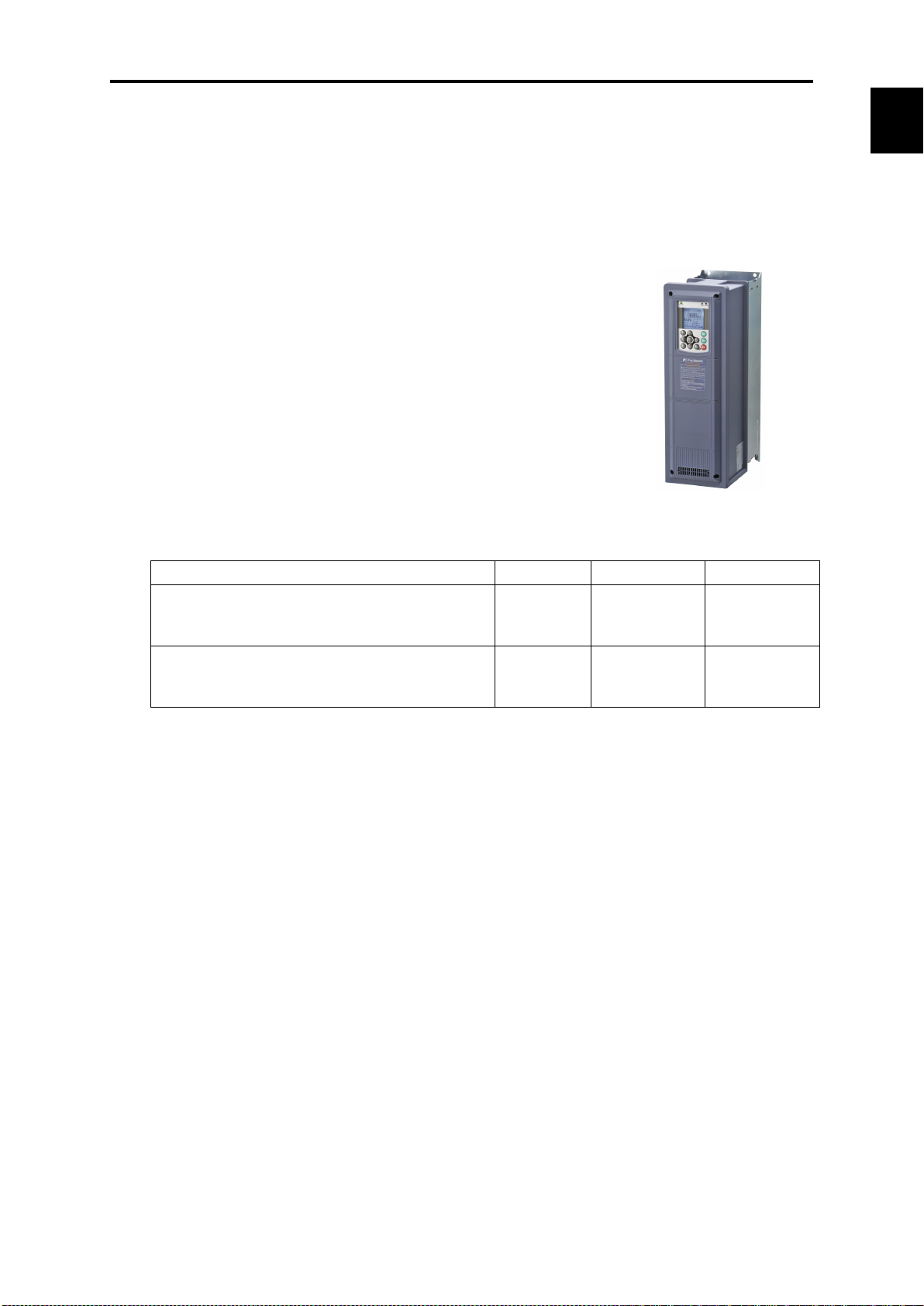
Overview
FRENIC-HVAC is Fuji Electric’s first “slim-type inverter specially designed for saving energy.”
The device is ideal for all kinds of applications related to systems for supplying water and treating
wastewater.
Achieving significant energy savings in HVAC by the optimal control.
Wide capacity range
∙ 1 to 125 HP / 230V
∙ 1 to 1000 HP / 460V
∙ 1 to 300 HP / 575V
Protective structure
∙ NEMA UL type1/ type12
∙ Open type
Equipped with DC reactor (DCR) / EMC filter
Inverter capacity EMC filter DC reactor Enclosure
1 to 125 HP ( Three-phase 460V series )
1 to 150 HP ( Three-phase 575V series )
075 to 125 HP ( Three-phase 230V series )
150 to 1000 HP ( Three-phase 460V series )
200 to 300 HP ( Three-phase 575V series )
Built-in Built-in
Built-in
Standard
accessory
NEMA UL
type1 / type12
Open
-HVAC
DCR:IEC/EN 61000-3-2, IEC/EN 61000-3-12
Functions suitable for HVAC use
1-1
Page 18
PID1 PV
+
-
PI D1 SV
偏差
最大選択
最小選択
プロセス指令値
フィードバック値
SV:Set Value
PV:Process Value
PID
調節器
正動作/
逆動作
演算器
速度指令
選択
PID制御
キャン セル
外部PID1出力
積分・微分リセット
積分ホールド
アン チリセットワイ ンドアップ
+
-
フィードバック
選択
PID2 PV
PID2 SV
プロセス指令値
PID
調節器
速度指令
選択
PID制御
キャン セル
外部PID2出力
正動作/
逆動作
積分・微分リセット
積分ホールド
アン チリセットワイ ンドアップ
+
-
フィードバック
選択
PID3 PV
PID3 SV
プロセス指令値
PID
調節器
正動作/
逆動作
PID制御
キャン セル
外部PID3出力
積分・微分リセット
積分ホールド
アン チリセットワイ ンドアップ
速度指令
選択
External PID output
∙
∙
Feedback value
Computing
Process command
value
Feedback
selection
Process command value
Integral hold
Integral/differential reset
Anti
Integral hold
Integral/differential reset
Anti
Integral hold
Integral/differential reset
Anti
Speed
selection
regulator
reverse
Deviation
External PID1 output
Cancel PID
control 1
Feedback
selection
control 2
Cancel PID
control 3
Speed
selection
Forward/
reverse
Forward/
reverse
External PID1 output
External PID1 output
PID
regulator
PID
SV: Set Value
PV: Process Value
Process command value
Speed
PID1 PV
演算器
+
-
PI D1 SV
+
-
フィードバッ ク
選択
偏差
最大選択
最小選択
PID制御2/1切換
PID
調節器
アン チリセッ トワイ ンド アップ
積分ホールド
積分・微分リセット
速度指令
選択
渇水保護
少水量停止機能
大水量保護
高頻度運転保護
フィルタ目詰まり/噛み込み防止
正動作/
逆動作
PID制御
キャン セル
周波数指令
PID2 PV
PID2 SV
プロセス指令値
フィードバッ ク値
プロセス指令値
SV:Set Value PV:Pr ocess Value
フィードバッ ク値
PID
Speed
command
PID
PV
PID2
SV
Computing
Process command value
Feedback
Process
command value
Feedback value
Feedback value
PID control 2/1 switching
PID control
Frequency
command
PID
regulator
Forward/
reverse
Integral hold
Integral/differential reset
Anti
up
Dry pump
detection
Slow flow rate
stop function
End of curve
detection
Control of maximum
starts per hour
PID2
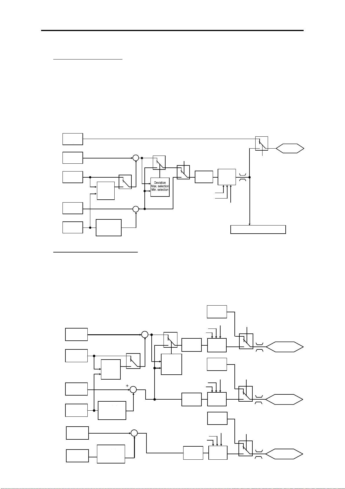
4PID control (standardly equipped with 4PID)
∙ PID control (for process)
Can be used by switching 2 types of process commands and feedback value. “Filter clogging /
anti-jam, deviation alarm / absolute value alarm output” have been added to PID regulator that
conducts temperature, pressure or flow rate control, etc. An anti-reset wind-up function to
prevent PID control overshoot and PID control function that can be easily adjusted by PID
limiter or integral fold / reset signal are furthermore employed.
PID control (process) block diagram
selection
1 SV
1
unit
-reset wind-
PV
selection
Filter clogging / anti-jam
∙ External PID control (process)
Equipped with 3 built-in external PID controllers. You can independently control external
actuators such as dampers and valves. An externally mounted PID controller is no longer
required, thereby enabling cost reduction.
External PID control (process) block diagram
command
-reset wind-up
Forward/
PID
Max. selection
Min. selection
command
-reset wind-up
Cancel PID
unit
command
selection
-reset wind-up
regulator
cancel
Y1-Y4 pins
⇒Pulse output
FM1/FM2 pins
⇒Analog output
1-2
Page 19
Chap. 1
About FRENIC
Power
source
voltage
Rotation
speed
Output
frequency
Current
Instantaneous
power failure
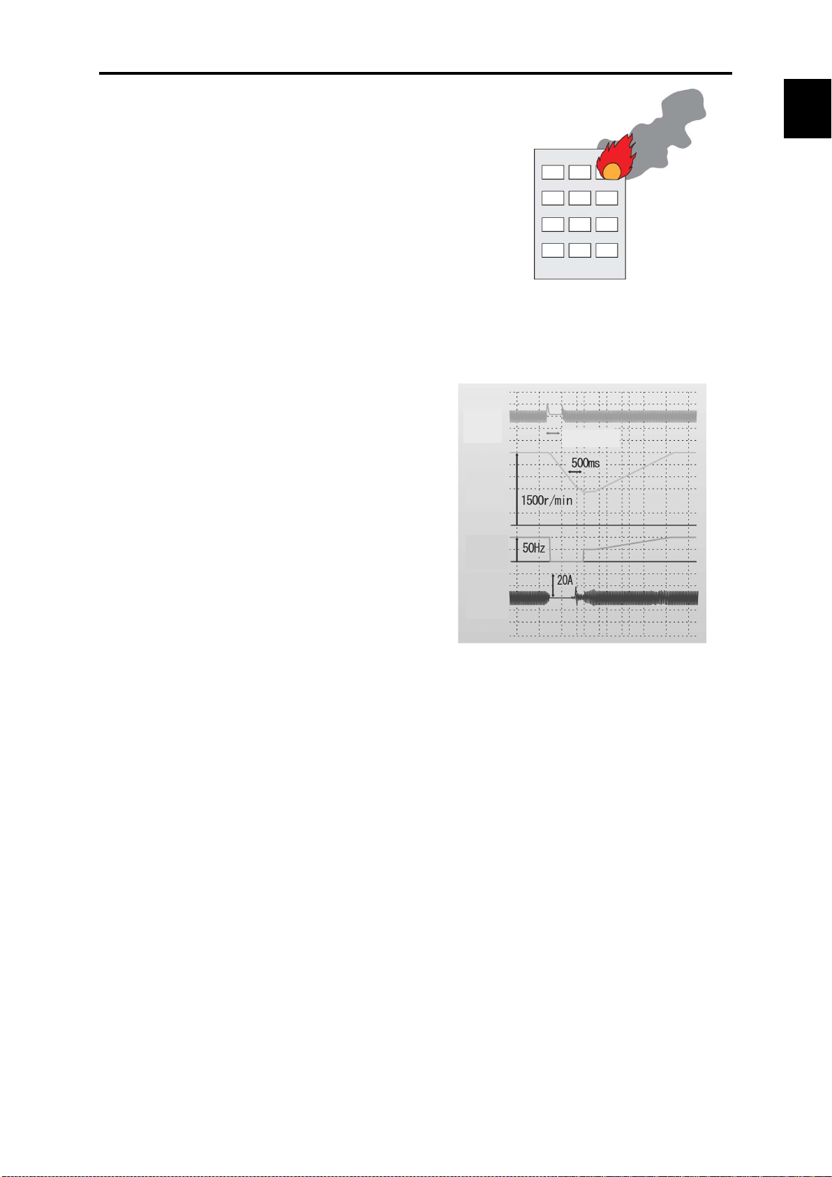
● Fire Mode (forced operation)
Alarm is ignored and operation continues
until the inverter is damaged, and evacuation
route is secured without smoke permeation.
Pick-up operation function (speed sensor)
Smooth start by pick-up function.
If operating fan while operating without a load
when the inverter is not operating, pick-up is
executed smoothly by searching for speed
regardless of rotation direction. Convenient
function when instantaneously switching from
commercial power supply to inverter or
restarting from instantaneous power failure.
1.1 Features
-HVAC
1-3
Page 20
Item
Content
Logic function
<Digital>
scale conversion
General-purpose
timer
On-delay, off-delay, pulse train, etc.
Time setting: 0.0–600s
Input/output signal
Terminal input/output, inverter control function
Others
Can comprise up to 14 steps, with each step input/output occurring in
having the LCD monitor.
(AND circuit + on-delay timer)
(Multiplication circuit + vertical limiter)
(Deviation comparison 2)
(Up counter)
(Conversion 1)
Y3 pin
output
12 pin
C1 pin
U04 U05 + - U09
Step 2
Step 1
Step 2
Example: Digital (AND + on
Example: Analog (subtraction + comparison 5)
Fref 0.00Hz
PRG>6>4
Step01:0021
RESET:Back to M
RESET:Back to M
Fref 0.00Hz
PRG>6>4
Step01:2052
RESET:Back to M
Fref 0.00Hz
PRG>6>4
Step01:0110
RESET:Back to M
Fref 0.00Hz
PRG>6>4
Step01:2151
RESET:Back to M
Fref 0.00Hz
PRG>6>4
Step01:3001
RESET:Back to M
Fref 0.00Hz
PRG>6>4
Step01:2003
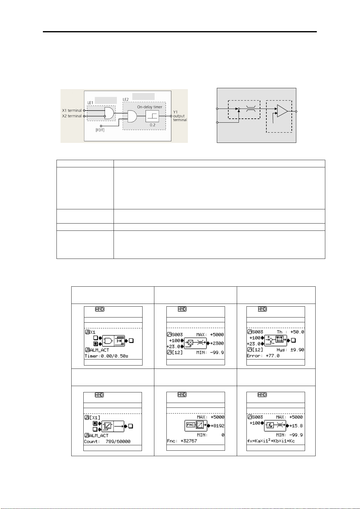
● Customizable logic
The customizable logic interface function is provided to the inverter body. This enables forming
of logic circuit and arithmetic circuit to the digital and analog input and output signals, allowing
simple relay sequence to be built while processing the signals freely.
-delay timer)
AND, OR, XOR, flip-flop, rise/fall detection, counter, etc.
<Analog>
Addition, subtraction, multiplication, limiter, absolute value, inverted
addition, comparison, max. value selection, min. value selection, avg.,
combination
You can check the input/output status of the various steps by the keypad
< LCD monitor example >
* Numerical values of the screen display are not the same as in actual circumstances.
Digital + digital + timer
Analog + analog + limiter
Digital + digital + counter
Function code + scale conversion Analog + 1 input + conversion
1-4
Analog + analog + comparison
Page 21
Chap. 1
About FRENIC
When operation is performed in the
When operation schedule varies
Run
command
Rotation
speed
DC
intermedi
ate circuit
voltage
Current
Time
Load status
Inverter temperature
Output frequency
OH trip
Time
1.1 Features
● Trip-less by regenerative avoidance control (effective for acceleration, deceleration
and fixed speed)
Because amount of energy to be regenerated to the inverter is limited and
acceleration/deceleration time is controlled, equipment can be operated without overvoltage
trip.
<Example: Operation when decelerating>
-HVAC
● Standardly equipped with Real time clock (RTC)
∙ Alarm information date/time display
∙ Timer operation function
∙ You can set up to 4 timers by units of 1 week.
∙ Holiday setting (20 days a year) is also possible.
∙ Daylight saving time auxiliary function
∙ Battery (optional) * Battery connection status displayed on the LCD monitor.
same schedule through a week
depending on the day of the week
● Continued operation of equipment by overload avoidance control
If the inverter becomes overloaded in the case where inverter internal temperature rises
radically from increased load or ambient temperature rises abnormally, operation is continued
by reducing the load by reducing motor speed.
1-5
Page 22
ELCB or
MCCB
Power
On/Off
Commercial/inverter
Built-in
Analog
equency
command
Command
loss detection
[REF OFF]
Time
Torque computation
value
Low torque
detection level
Time
Power
Transistor output
Broken
belt!
Regular frequency
setting
Output
frequency
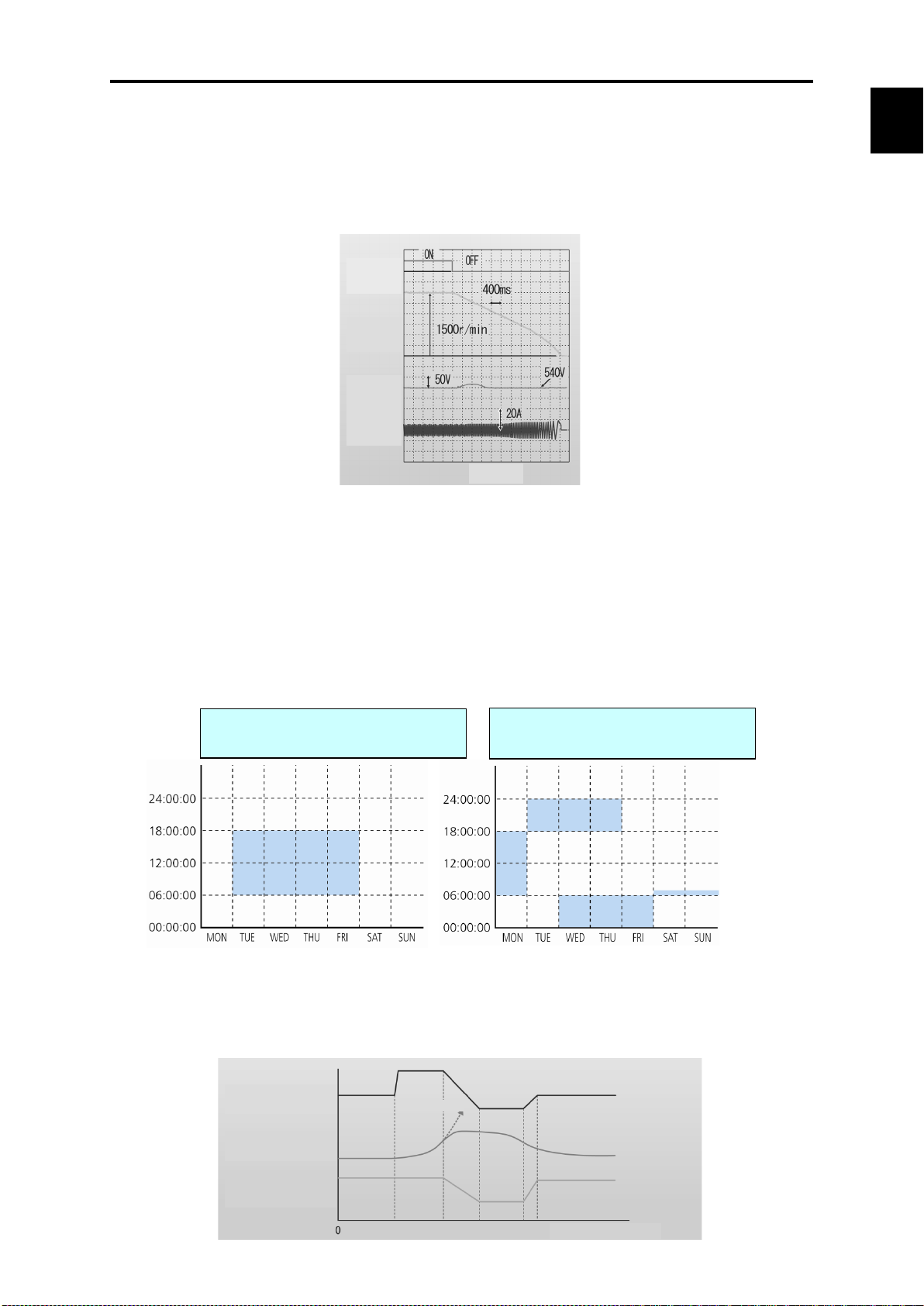
● Commercial operation switching
Because the inverter is equipped with a commercial frequency start processing function for
switching commercial / inverter operation by external sequence, peripheral equipment
configuration can be simplified. The inverter is equipped with 2 types of commercial operation
switching sequences: Fuji standard and inverter alarm automatic commercial switching
sequence.
FRENIC-HVAC
sequence
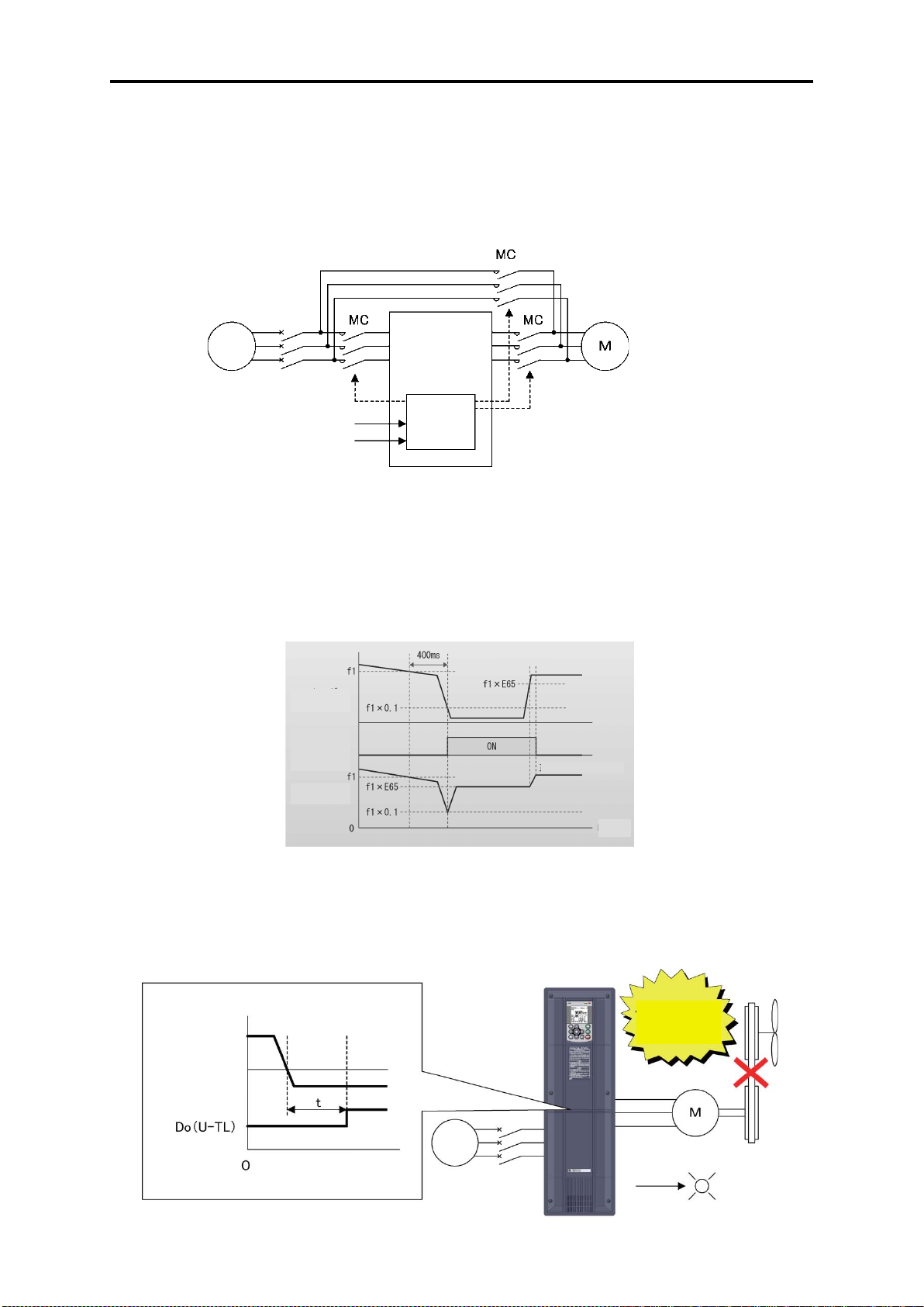
● Operation signal trouble is also avoided by command loss detection function.
If the frequency signal connected to the inverter (0 - 10V, 4 - 20 mA, multiple stage speed
operation signal, communication, etc.) is blocked, the fact that frequency command has been
lost is output as a “command loss” signal. You can furthermore set output frequency for
command loss in advance, so the equipment can continue to operate even if the frequency
signal is cut off by mechanical vibration, etc.
fr
● Low torque detection also possible
If a problem such as fan belt breaking and load connected to the motor becomes exponentially
lighter all of a sudden, detects that torque has dropped and outputs it as an output signal.
Abnormal status of the equipment can be detected using this signal, so it can be utilized as
equipment maintenance information.
1-6
Page 23
Chap. 1
About FRENIC
Inverter control (V/f control)
Required
Example of features when using damper
or valve
Energy
conservation
effect
Air flow or flow rate (%)
Inverter control
(For automatic energy
control)
● Password function
Function codes can be read/write, displayed or hidden by setting the two passwords. This
prevents erroneous operation or overwriting of function codes. In addition, if a wrong password
was input exceeding the specified number of times, the inverter is restricted from operating as
the user is regarded as improper.
1.1 Features
-HVAC
● Filter clogging prevention function
This function detects clogging of the fan filter with dust or other materials using the output
current and pressure sensor value. When clogging is detected, the fan is rotated in reverse
to eject dust, and then resumes rotation in forward to blow air. In addition, the function notifies
you of maintenance necessity with the alarm signal.
Equipped with function that contributes to energy conservation.
Automatic energy-saving operation
Considering that fact that “control that minimizes motor loss” has evolved and the loss of the
inverter itself, the device has been “equipped with a new type of control to minimize loss of the
motor plus the inverter” to further conserve electric power for fan and pump applications.
power (%)
*Effect differs according to motor characteristics
Example of energy saving effect characteristics
1-7
Page 24
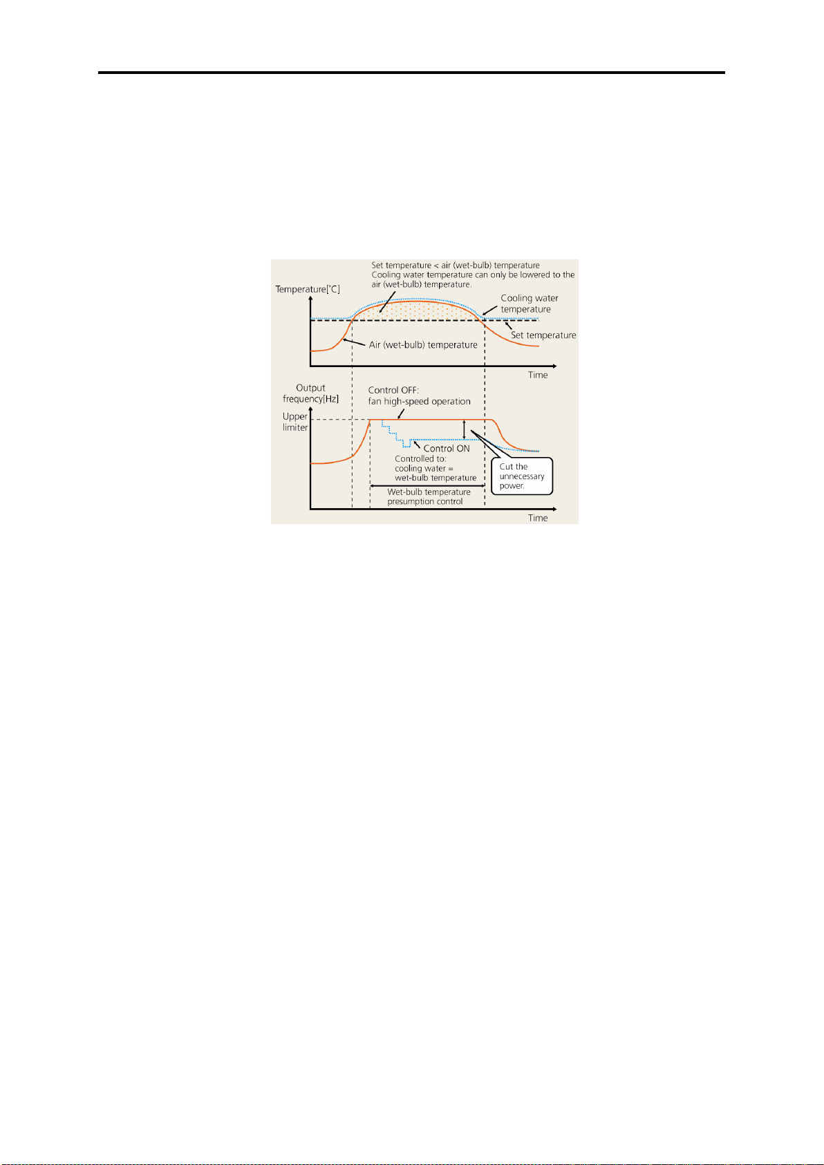
● Wet-bulb temperature presumption control
This function is optimal for controlling the fan of cooling tower. Since the wet-bulb temperature
would become higher than the set temperature when the air temperature is particularly high,
water temperature will not reach the set temperature. Therefore, the fan keeps rotating at high
speed, failing in energy-saving operation. FRENIC-HVAC automatically estimates
the wet-bulb temperature and controls the fan so that the cooling water is interlocked with the air
temperature in order not to use unnecessary electric power.
1-8
Page 25
Chap. 1
About FRENIC
Refrigeration machine
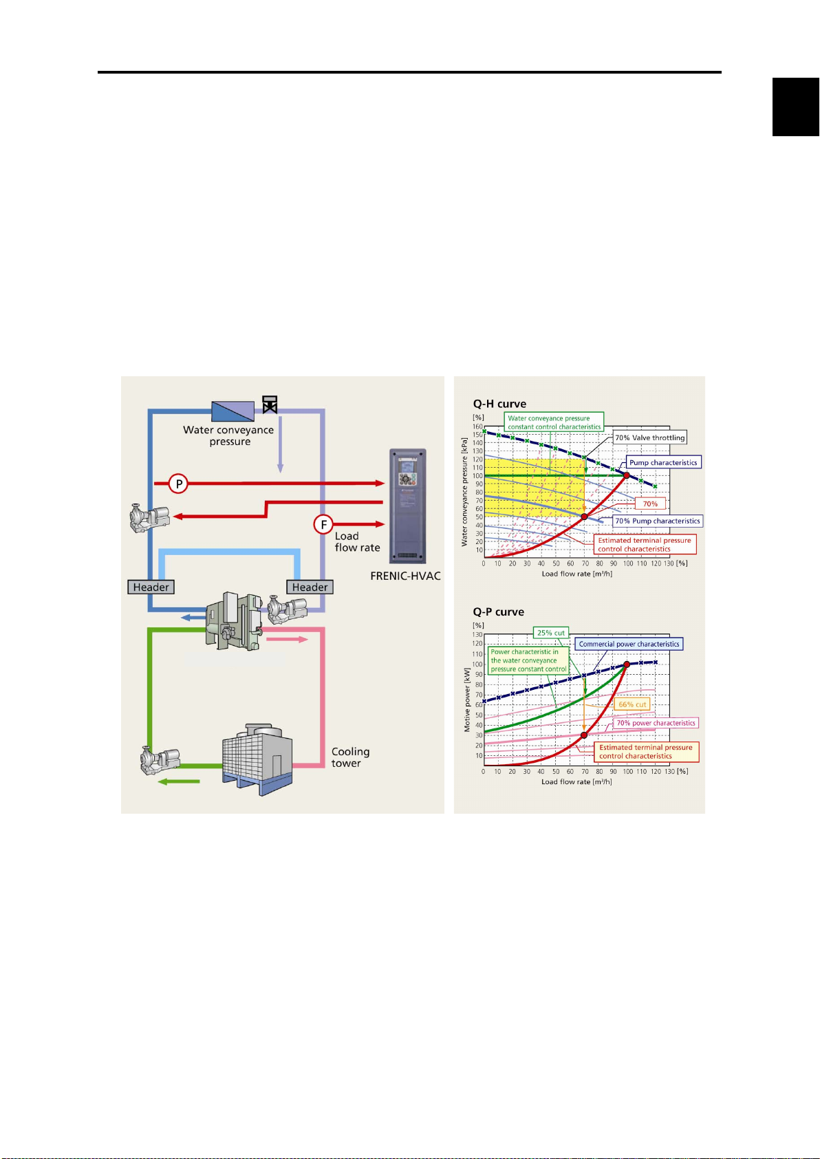
● Linearization function
This function estimates the target pressure using the load flow rate, which allows the estimated
terminal pressure to be controlled. For an air-conditioning heat source system, the needed
quantity of the cooling or heating water fluctuates generally in seasons or days and nights.
Therefore, operations continuing in a water conveyance pressure constant control may lead to
high operating unnecessary pressures on terminals at low operating state. Thus, the pump
consumes an ineffectual electric power for maintaining the high water conveyance pressure.
↓
Based on the calculated value and water conveyance pressure of estimated terminal pressure
using the detected load flow rate, PID control is performed.
↓
It is possible to reduce the ineffectual pump power consumption and to achieve a great
energy-saving effect together with maintaining comfortable current air conditioning.
1.1 Features
-HVAC
Enhanced network support
Standard equipment
∙ Modbus RTU ∙ Metasys N2 ∙ BACnet
Optional cards
∙ PROFIBUS-DP ∙ CC-Link ∙ DeviceNet ∙ CANopen
∙ LONWORKS ∙ Ethernet
1-9
Page 26
Item
Objective
Motor cumulative
Keeps track of time that equipment (motor) using the inverter is actually running.
pulleys.
Startup count (times)
Counts the number of times the inverter is turned on and off.
machinery when turned on and off.
Simple and enhanced maintenance / enhanced protective functions.
Information concerning life of consumable inverter parts is displayed.
Main circuit capacitance
Cooling fan cumulative running time
(Equipped with cooling fan ON/OFF
control compensation)
Inverter cumulative running
time
Electrolytic capacitors on PC board
Cumulative running time
Life warning signal can be output to transistor output.
Output when the end of service life of main circuit capacitors, electrolytic capacitors on PC board,
cooling fan, or real time lock battery (optional) approaches.
Information taking equipment maintenance into account is also displayed.
Information is added to maintenance information for the inverter itself and information taking
equipment maintenance into account is also displayed.
running time (h)
(Usage example)
If used for fan control, it approximates the time for replacement of belts used for
(Usage example)
Because it keeps a record of how many times the equipment is turned on and off, it
approximates the times for replacement of equipment parts that place a load on
You can check alarm history for the past 10 times (latest and 9 past times).
Detailed information can also be checked for the past 4 times.
If using a real time clock, you can check the date and time of occurrence.
Employs detachable interface board (terminal block for control signal line)
1-10
Page 27
Chap. 1
About FRENIC
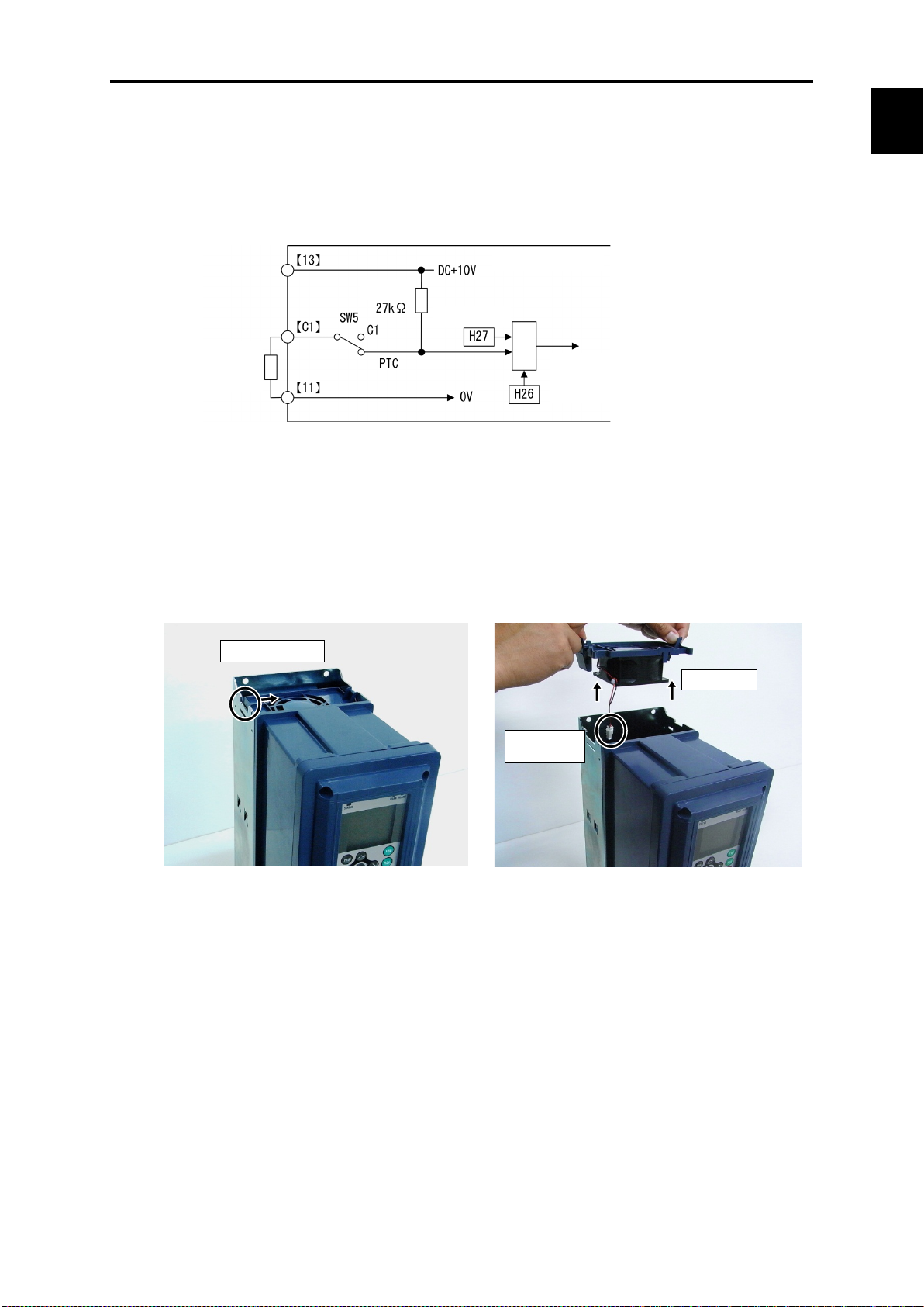
<
PTC
thermistor
Comparator
External
alarm
Resistor
(Power level)
Press knob inward.
Lift carefully.
Disconnect
the connector.
Remove the cooling fan (with case).
Remove cooling fan cable (connector).
Remove and replace the fan case and
cooling fan.
1.1 Features
Motor protection by PTC thermistor
By connecting the Positive Temperature Coefficient (PTC) thermistor embedded in the motor to
the C1 pin, motor temperature is detected to protect the motor by shutting off the inverter before
the motor overheats. You can select whether to shut off the inverter (stop by alarm) or output
alarm from transistor output by PTC protection level.
Control circuit>
-HVAC
Easy cooling fan replacement
Employs configuration that allows the fan to be mounted or dismounted by one simple operation
to facilitate cooling fan replacement. (For the detailed replacement procedure, refer to Chapter 10,
Section 10.6 "Cooling Fan Replacement Procedure.")
Cooling fan replacement procedure
1-11
Page 28
Language
English
Chinese
German
French
Spanish
Italian
Russian
Greek
Turkish
Malay
Vietnamese
Thai
Indonesian
Polish
Czech
Swedish
Portuguese
Dutch
Japanese
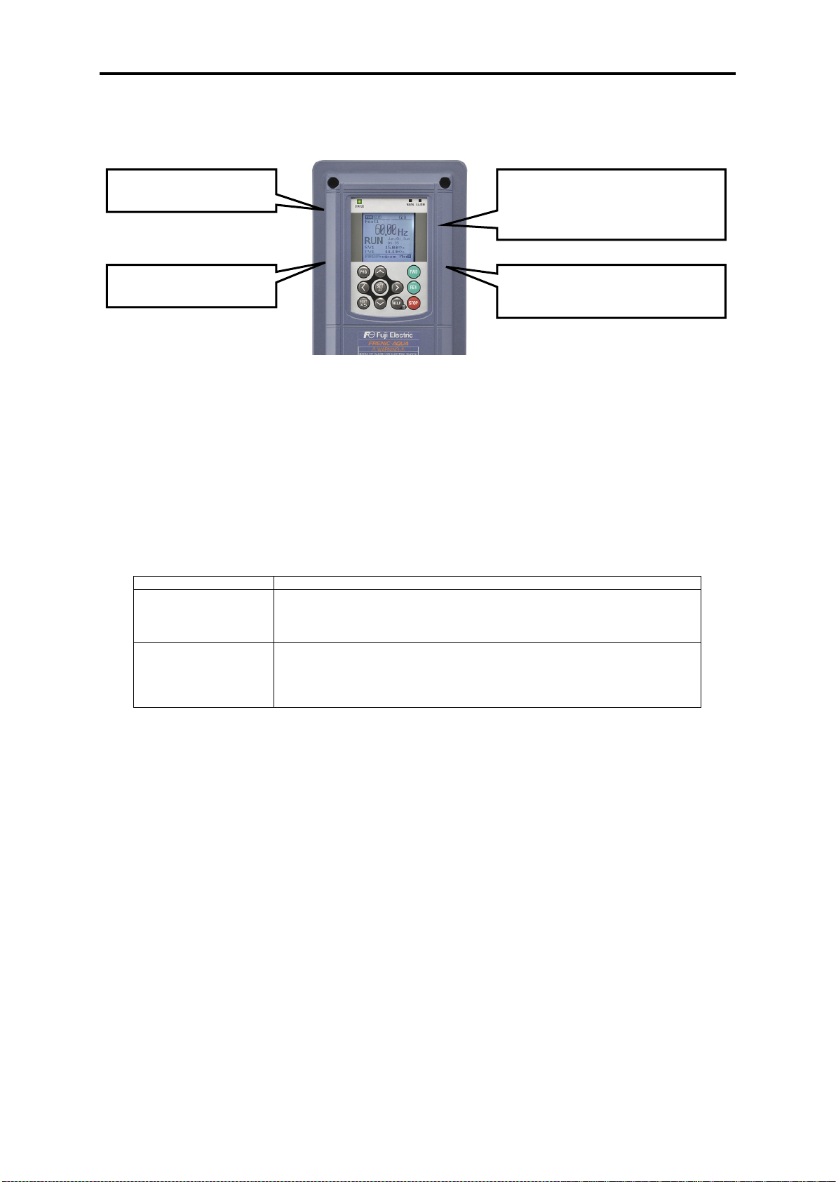
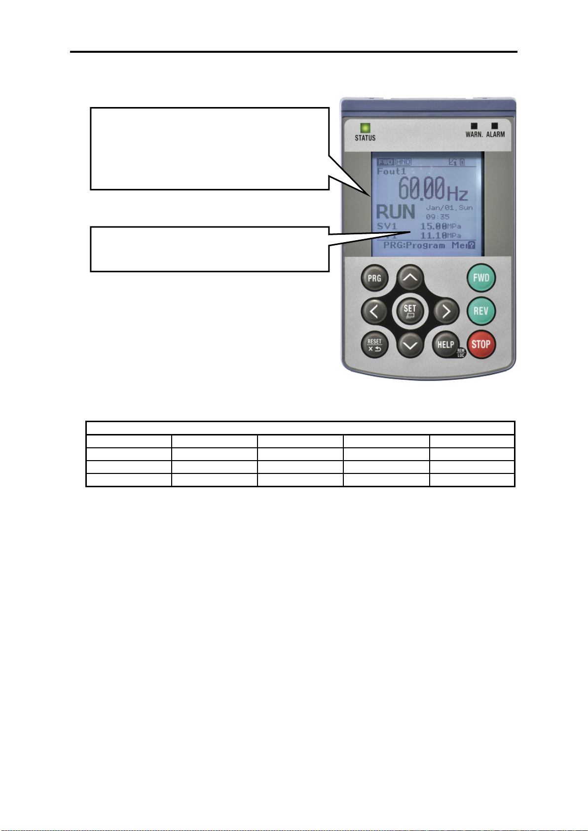
Equipped with keypad employing large LCD.
∙ Realizes regulator display by enlargement of LCD.
1. Present value (PV) 6. Output voltage
2. Setting value (SV)
3. Manipulating value (MV)
4. Frequency 9. Power consumption
5. Output current 10. Cumulative energy
7. Torque
8. Rotation speed
Unit setting function enables
easy-to-understand display.
∙ Multi-language supported: 19 languages + user customized language
1-12
Page 29
Chap. 1
About
1.2 Inspection of goods and product appearance
1.2 Inspection of goods and product appearance
1.2.1 Inspection of goods
Unpack the package and check the following:
(1) An inverter and the following accessories are contained in the package.
Accessories: Instruction manual and CD-ROM manual
(2) The inverter has not been damaged during transportation—there should be no dents or parts
missing.
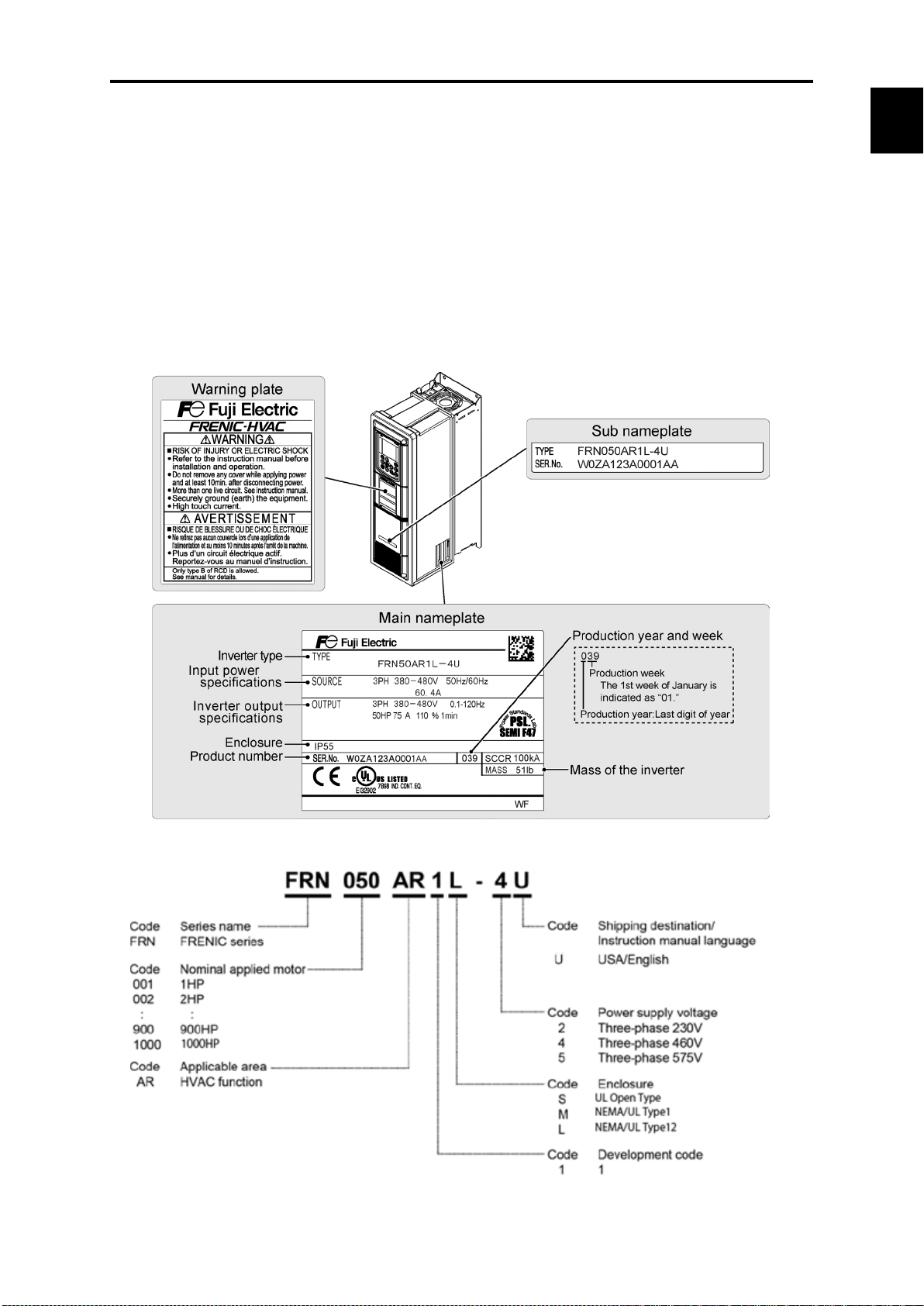
(3) The inverter is the type you ordered. You can check the type and specifications on the main
nameplate. (A total of four nameplates and warning plates are attached to the inverter as shown
below.)
FRENIC-HVAC
①Type: Inverter type
“Nominal applied motor” for USA models are represented in the HP unit.
1-13
Page 30

The alphabetical character that indicates protective structure goes in .
②Source: Input power source specifications
No. of input phases (3PH in the case of 3 phases), input voltage, input frequency, input current
③Output: Inverter output specifications
No. of output phases, rated output voltage, output frequency range, output rated capacity,
rated output current, overload current rating
④IP Code: Protective structure
⑤⑥Ser. No: Serial No. / Mfg. Year/week
W18A123A0001AA 039
The first week of mfg. week / January is “01.”
This indicates which week it corresponds to.
Mfg. year / last digit of year
⑦Mass: Mass
Inverter type is indicated as "FRN***AR1-2U/4U/5U" in the various tables in this document.
If there is something you do not understand about the product or there is something wrong with it,
please contact the dealership from where you purchased it or your nearest Fuji Electric sales office.
1-14
Page 31

Chap. 1
About
Fig. 1.1 FRN001AR1M-4U (NEMA/UL type1)
Fig. 1.2 FRN300AR1S-4U (UL open type)
Cooling fan
Front cover
Caution label
Ratings label
Main circuit terminal block
Control circuit terminal block
Front cover
Front cover
mounting screw
Keypad
Internal
agitator fan
1.2.2 Product appearance
1.2 Inspection of goods and product appearance
FRENIC-HVAC
Note: Refer to external drawings in chapter 2 for other capacities.
1-15
Page 32

Chapter 2
SPECIFICATIONS
This chapter describes specifications of the output ratings, control system, and terminal functions for the
FRENIC-HVAC series of inverters. It also provides descriptions of the operating and storage environment,
precautions for using inverters, external dimensions, examples of basic connection diagrams, and details of
the protective functions.
Contents
2.1 Standard Model FRENIC-HVAC .............................................................................................................. 2-1
2.1.1 Three-phase 230 V class series (USA models) .................................................................................... 2-1
2.1.2 Three-phase 460 V class series (USA models) ................................................................................... 2-3
2.1.3 Three-phase 575 V class series (USA models) ................................................................................... 2-6
2.2 Common Specifications .............................................................................................................................. 2-9
2.3 Terminal Specifications ............................................................................................................................. 2-16
2.3.1 Terminal functions ............................................................................................................................ 2-16
2.3.2 Setting up the slide switches ............................................................................................................. 2-26
2.3.3 Screw specifications and recommended wire sizes ........................................................................... 2-28
2.3.3.1 Main circuit terminals ............................................................................................................... 2-28
2.3.3.2 Control circuit terminals (Common to all inverter types) ......................................................... 2-35
2.4 Conduits .................................................................................................................................................... 2- 36
2.4.1 Conduits ............................................................................................................................................ 2-36
2.5 Leakage Current of the EMC Filter........................................................................................................... 2-39
2.6 Derating of Rated Output Current ............................................................................................................. 2-42
2.7 Operating Environment and Storage Environment ................................................................................... 2-44
2.7.1 Operating environment ...................................................................................................................... 2-44
2.7.2 Storage environment ......................................................................................................................... 2-45
2.7.2.1 Temporary storage ..................................................................................................................... 2-45
2.7.2.2 Long-term storage ..................................................................................................................... 2-45
2.8 Precautions for Using Inverters ................................................................................................................. 2-46
2.8.1 Precautions in introducing inverters .................................................................................................. 2-46
2.8.2 Precautions in running inverters ........................................................................................................ 2-50
2.8.3 Precautions in using special motors .................................................................................................. 2-50
2.9 External Dimensions ................................................................................................................................. 2- 51
2.9.1 Standard models ................................................................................................................................ 2- 51
2.9.2 Keypad .............................................................................................................................................. 2-64
2.10 Connection Diagrams ................................................................................................................................ 2-65
Page 33

Page 34
Chap. 2
SPECIFICATIONS
Item
Specifications
Type
(FRN_ _ _AR1-2U) (*1)
Nominal
Three
AC208V
motor
AC230V
motor
Single
AC208V
motor
AC230V
motor
Three
Rated capacity (kVA)
(*3)
Rated current (A)
5 8 11
18
27
31.8
46.2
59.4
74.8
88
115
146
180
215
283
346
Single
Rated capacity (kVA)
(*3)
Rated current (A)
1.9
3.1
4.2 7 10.5
12.4
18
23.1
29.1
34.3
44.8
56.9
70.2
95
102
131
Rated voltage (V) (*4)
Three-phase, 200 to 240 V (with AVR function)
Three-phase, 200 to 230 V (with AVR function)
Overload capability
110%-1 min (Overload interval: Compliant with IEC 61800-2)
Main power supply
voltage, frequency)
Rated current (A) (*5)
2.8
5.3
7.5
12.9
18.0
24.2
36.0
48.6
60.0
71.5
96.9
121
145
177
246
291
Required power
supply capacity [kVA]
Main power supply
voltage, frequency)
Rated current [A] (*5)
2.8
5.3
7.5
12.9
18.0
24.2
36.0
48.6
60.0
71.5
96.9
121
145
177
246
291
Required power
supply capacity [kVA]
Auxiliary control power supply:
frequency)
Auxiliary main power supply
frequency) (*6)
Voltage, frequency variations
Voltage: +10 to -15% (Interphase voltage unbalance : 2% or less) (*9), Frequency: +5 to -5%
Brak-
ing
Braking torque [%] (*7)
DC injection braking
EMC filter (IEC/EN 61800-3) (*8)
EMC standards compliance : Category C2 (emission) / 2nd Env. (Immunity)
C3/ 2nd
Standard
(IEC/EN61000-3-12)
load)
Fundamental wave
power factor
Total power factor
≥ 0.90
Efficiency (at the rated load) (%)
97
97
97
97
97
98
98
98
98
98
98
98
98
98
98
98
Applicable (safety) standards
UL 508C, C22.2 No. 14, IEC/EN 61800-5-1 SEMI F47-0706
Cooling method
Fan cooling
Weight / Mass
NEMA/UL Type 1
22
22
22
22
40
40
40
51
51
110
110
154
154
NEMA/UL Type 12
22
22
22
22
40
40
40
51
51
110
110
154
154
UL open type
-
93
95
137
Site location
Indoors
UL open type /
UL Type 1
NEMA/
UL Type 12
Relative humidity
5 to 95% (No condensation)
The inverter must not be exposed to dust, direct sunlight, corrosive gases, flammable gases, oil mist, vapor or water
drops. Pollution degree 2 (IEC/EN 60664-1) (*12)
The atmosphere can contain a small amount of salt. (0.01 mg/cm2 or less per year)
The inverter must not be subjected to sudden changes in temperature that will cause condensation to form.
Altitude
3,300 ft max. (*13)
Atmospheric pressure
86 to 106 kPa
60 HP or less
75 to 100 HP
1 m/s2 55 to less than 200 Hz
125 HP
2.1 Standard Model FRENIC-HVAC
2.1.1 Three-phase 230 V class series (USA models)
(001 to 125 HP)
001 002 003 005 007 010 015 020 025 030 040 050 060 075 100 125
2.1 Standard Model
applied motor
[HP] (*2)
phase
input
(Rated output)
phase
input
phase
input
phase
input
Output ratings
(number of phases,
Three
phase
input
(number of phases,
Single
phase
input
Input power
(number of phases, voltage,
(number of phases, voltage,
1 2 3 5 7.5 10 15 20 25 30 40 50 60 75 100 125
- 1/2 3/4 1.5 2 3 5 5 7.5 10 10 15 20 30 30 40
- 1/2 1 2 3 3 5 7.5 10 10 15 20 25 30 30 50
1.9 3.1 4.3 7.1 10 12 18 23 29 35 45 58 71 85 112 137
0.7 1.2 1.6 2.7 4.1 4.9 7.1 9.2 11 13 17 22 27 37 40 52
Three-phase, 200 to 240 V, 50/60 Hz
Three-phase, 200 to 220 V, 50 Hz
Three-phase, 200 to 230 V, 60 Hz
1.2 2.2 3.0 5.2 7.2 10 15 20 24 29 39 49 58 71 98 116
Single-phase, 200 to 240 V, 50/60 Hz
Single-phase, 200 to 220 V, 50 Hz
Single-phase, 200 to 230 V, 60 Hz
0.7 1.3 1.8 3.0 4.2 5.6 8.3 12 14 17 23 28 34 41 57 67
Single-phase , 200 to 240 V, 50/60 Hz Single-phase, 200 to 230 V, 50/60 Hz
-
Single-phase, 200 to 220 V, 50 Hz
Single-phase, 200 to 230 V, 60 Hz
20 10 to 15
Braking start frequency: 0.0 to 60.0 Hz; Braking time: 0.0 to 30.0 s; Braking operation level: 0 to 60%
DC reactor (DCR) (*8) Built-in (IEC/EN 61000-3-2(*10), IEC/EN 61000-3-12)
Power factor
(at the rated
> 0.98
accessory
Enclosure NEMA/UL 50 NEMA/UL Type 1, NEMA/UL Type 12(*11) UL open type
[lbs]
Ambient
NEMA/
14 to 122°F
-
temperature
14 to 104°F
Atmosphere
Environmental Requirements
Vibration
3 mm 2 to less than 9 Hz
10 m/s2 9 to less than 200 Hz
3 mm 2 to less than 9 Hz
9.8 m/s2 9 to less than 20 Hz
2 m/s2 20 to less than 55 Hz
3 mm 2 to less than 9 Hz
2 m/s
1 m/s
2
9 to less than 55 Hz
2
55 to less than 200 Hz
2-1
Page 35

Altitude
3300 ft or lower
3300 to 4900 ft
4900 to 6600 ft
6600 to 8200 ft
8200 to 9800 ft
Output current derating factor
1.00
0.97
0.95
0.91
0.88
(*1) A box () replaces an alphabetic letter depending on the enclosure.
Enclosure: M (NEMA/UL Type1), L (NEMA/UL Type12) or S (UL Open Type)
(*2) US 4-pole standard induction motor.
(*3) Rated capacity is calculated by assuming the output rated voltage as 230 V.
(*4) Output voltage cannot exceed the power supply voltage. At single-phase input use, the output voltage may be lower than three-phase input.
(*5) The value is calculated on assumption that the inverter is connected with a power supply 230V, 50Hz and Rsce=120.
(*6) The auxiliary power input is used as an AC power input when combining the unit to DC power supply such as high power factor PWM converter
with power regenerative function. (Generally not to be used.)
(*7) Average braking torque for the motor running alone. (It varies with the efficiency of the motor.)
(*8) EMC filters and DCR does not conform to each corresponding standards when single phase input use.
(*9) Voltage unbalance [%] = (Max. voltage [V] - Min. voltage [V])/Three-phase average voltage [V] x 67 (See IEC/EN61800-3.)
If this value is 2 to 3%, use an optional AC reactor (ACR).
(*10) It is applicable when the power supply is supplied from 3-phase 200V series transformer which is through 3-phase 400V series transformer.
(*11) NEMA/UL Type 12 offers protection for short water jets. Do not use outdoors or in places where long-term waterproofing is required.
(*12) Do not install the inverter in an environment where it may be exposed to lint, cotton waste or moist dust or dirt which will clog the heat sink of the
inverter. If the inverter is to be used in such an environment, install it in a dustproof panel of your system.
(*13) If you use the inverter in an altitude above 3300 ft, you should apply an output current derating factor as listed in the table below.
2-2
Page 36
Chap. 2
SPECIFICATIONS
Item
Specifications
Type
(FRN_ _ _AR1-4U) (*1)
Nominal
Three
input
AC460V
Single
input
Three
Rated capacity (kVA)
(*3)
Rated current (A)
2.5
4.1
5.5
9.0
13.5
18.5
24.5
32
39
45
60
75
91
112
Single
Rated capacity (kVA)
(*3)
Rated current (A)
-
1.5
2.1
3.5
5.2
7.2
9.5
12.4
15.2
17.5
23.4
29.2
35.4
43.6
Rated voltage (V) (*4)
Three-phase, 380 to 480 V (with AVR function)
Overload capability
110%-1 min (Overload interval: Compliant with IEC 61800-2)
Three
Main power supply
Three-phase, 380
phase, 380
to 480 V, 60 Hz
Rated current (A) (*5)
1.4
2.7
3.8
6.5
9.0
12.1
18.0
24.3
30.0
35.8
48.5
60.4
72.3
88.7
Required power
supply capacity [kVA]
Single-phase, 380
to 480 V, 60 Hz
Rated current [A] (*5)
-
2.7
3.8
6.5
9.0
12.1
18.0
24.3
30.0
35.8
48.5
60.4
72.3
88.7
Required power
supply capacity [kVA]
Auxiliary control power
frequency)
Single-phase, 380
to 480 V, 60 Hz
Voltage, frequency variations
Voltage: +10 to -15% (Interphase voltage unbalance : 2% or less) (*9), Frequency: +5 to -5%
Brak-
ing
Braking torque [%] (*7)
20
10 to 15
DC injection braking
EMC filter (IEC/EN 61800-3) (*8)
EMC standards compliance : Category C2 (emission) / 2nd Env. (Immunity)
DC reactor (DCR) (*8)
Built-in (IEC/EN 61000-3-2(*10), IEC/EN 61000-3-12)
load)
Fundamental wave
power factor
Total power factor
≥ 0.90
Efficiency (at the rated load) (%)
95
96
97
97
97
97
97
97
98
98
98
98
98
98
Applicable (safety) standards
UL 508C, C22.2 No. 14, IEC/EN 61800-5-1, SEMI F47-0706
Enclosure
NEMA/UL 50
NEMA/UL Type 1, NEMA/UL Type 12 (*11)
Cooling method
Fan cooling
Weight / Mass
NEMA/UL Type 1
22
22
22
22
22
22
40
40
40
40
51
51
110
110
NEMA/UL Type 12
22
22
22
22
22
22
40
40
40
40
51
51
110
110
UL open type
-
Site location
Indoors
UL open type /
UL Type 1
NEMA/
UL Type 12
Relative humidity
5 to 95% (No condensation)
The inverter must not be exposed to dust, direct sunlight, corrosive gases, flammable gases, oil mist, vapor or
water drops. Pollution degree 2 (IEC/EN 60664-1) (*12)
The atmosphere can contain a small amount of salt. (0.01 mg/cm2 or less per year)
The inverter must not be subjected to sudden changes in temperature that will cause condensation to form.
Altitude
3,300 ft max. (*13)
Atmospheric pressure
86 to 106 kPa
3mm 2 to less than 9 Hz
10 m/s2 9 to less than 200 Hz
2.1.2 Three-phase 460 V class series (USA models)
(1 to 75 HP)
001 002 003 005 007 010 015 020 025 030 040 050 060 075
2.1 Standard Model
applied motor
[HP] (*2)
(Rated output)
phase
input
phase
input
Output ratings
phase
input
Single
phase
input
Input power
supply:
(number of phases, voltage,
Auxiliary main power supply
(number of phases, voltage,
frequency) (*6)
phase
phase
(number of phases,
voltage, frequency)
Main power supply
(number of phases,
voltage, frequency)
motor
1 2 3 5 7.5 10 15 20 25 30 40 50 60 75
- 1/2 1 2 3 3 5 7.5 10 10 15 20 25 30
1.9 3.2 4.3 7.1 10 14 19 25 31 35 47 59 72 89
- 1.1 1.6 2.7 4.1 5.7 7.5 9.8 12 13 18 23 28 34
Three-phase, 380 to 480 V, 50/60 Hz
1.2 2.2 3.1 5.2 7.2 10 15 20 24 29 39 49 58 71
Single-phase, 380 to 480 V, 50/60 Hz
- 1.3 1.8 3.0 4.2 5.6 8.3 12 14 17 23 28 34 41
Single-phase, 380 to 480 V, 50/60 Hz
-
to 440 V, 50 Hz
Three-
to 440 V, 50 Hz
Single-phase, 380
to 440 V, 50 Hz
Single-phase, 380
Braking start frequency: 0.0 to 60.0 Hz; Braking time: 0.0 to 30.0 s; Braking operation level: 0 to 60%
Power factor
(at the rated
[lbs]
Ambient
temperature
Atmosphere
Environmental Requirements
Vibration
NEMA/
> 0.98
14 to 122°F
14 to 104°F
2-3
Page 37

Item
Specifications
Type
(FRN_ _ _AR1-4U) (*1)
Nominal
Three
input
AC460V
Single
input
Three
Rated capacity (kVA)
(*3)
Rated current (A)
150
176
210
253
304
377
415
520
650
740
960
1170
1370
Single
Rated capacity (kVA)
(*3)
Rated current (A)
58.5
68.6
81.9
98.6
118
147
161
202
253
288
374
456
534
Rated voltage (V) (*4)
Three-phase, 380 to 480 V (with AVR function)
Overload capability
110%-1 min (Overload interval: Compliant with IEC 61800-2)
Three
Main power supply
voltage, frequency)
Rated current (A) (*5)
119
141
175
207
249
311
340
435
547
614
767
970
1093
Required power
supply capacity [kVA]
Main power supply
voltage, frequency)
Rated current [A] (*5)
119
141
175
207
249
311
340
435
547
614
767
970
1093
Required power
supply capacity [kVA]
Auxiliary control power supply:
frequency)
Auxiliary main power supply
frequency) (*6)
Voltage, frequency variations
Voltage: +10 to -15% (Interphase voltage unbalance : 2% or less) (*9), Frequency: +5 to -5%
Brak-
ing
Braking torque [%] (*7)
10 to 15
DC injection braking
Braking start frequency: 0.0 to 60.0 Hz; Braking time: 0.0 to 30.0 s; Braking operation level: 0 to 60%
EMC filter (IEC/EN 61800-3) (*8)
C2/2nd
EMC standards compliance: Category C3 (emission) / 2nd Env. (Immunity)
Built-in (IEC/EN
IEC/EN
61000-3-12)
Fundamental wave
power factor
Total power factor
0.90
Efficiency (at the rated load) (%)
98
98
98
98
98
98
98
98
98
98
98
98
98
Safety standard compliance
UL 508C, C22.2 No. 14 , IEC/EN 61800-5-1, SEMI F47-0706
NEMA/UL Type
Type 12(*11)
Cooling method
Fan cooling
Weight /
NEMA/UL Type 1
154
154 - NEMA/UL Type 12
154
154
UL open type
-
137
141
207
216
284
309
540
540
728
1168
1168
Site location
Indoors
UL open type /
UL Type 1
NEMA/
UL Type 12
Relative humidity
5 to 95% (No condensation)
The inverter must not be exposed to dust, direct sunlight, corrosive gases, flammable gases, oil mist, vapor or
water drops. Pollution degree 2 (IEC/EN 60664-1) (*12)
The atmosphere can contain a small amount of salt. (0.01 mg/cm2 or less per year)
The inverter must not be subjected to sudden changes in temperature that will cause condensation to form.
Altitude
3,300 ft max. (*13)
Atmospheric pressure
86 to 106 kPa
100 to 125 HP or less
150 to 1000 HP
1m/s2 55 to less than 200 Hz
(100 to 1000 HP)
100 125 150 200 250 300 350 450 500 600 800 900 1000
applied
motor (HP)
(*2)
(Rated
output)
Output ratings
Input power
phase
phase
phase
input
phase
input
phase
(number of phases,
input
(number of phases,
Single
phase
input
(number of phases, voltage,
(number of phases, voltage,
motor
100 125 150 200 250 300 350 450 500 600 800 900 1000
40 50 60 75 75 100 125 150 200 200 300 350 450
119 140 167 201 242 300 330 414 517 589 764 932 1091
46 54 65 78 94 117 128 160 201 229 297 363 425
Three-phase, 380 to 440 V, 50 Hz
Three-phase, 380 to 480 V, 60 Hz
95 113 140 165 199 248 271 347 436 490 612 773 871
Single-phase, 380 to 440 V, 50 Hz
Single-phase, 380 to 480 V, 60 Hz
55 65 81 96 115 144 157 201 252 282 353 447 503
Single-phase, 380 to 480 V, 50/60 Hz
Single-phase, 380 to 440 V, 50 Hz
Single-phase, 380 to 480 V, 60 Hz
DC reactor (DCR) (*8)
Power factor
(at the rated
load)
Enclosure
Mass [lbs]
Environmental Requirements
NEMA/UL 50
Ambient
temperature
Atmosphere
Vibration
NEMA/
61000-3-2
(*10),
> 0.98
≥
1, NEMA/UL
14 to 122°F
14 to 122°F
3mm 2 to less than 9 Hz
2
10 m/s
Standard accessory (IEC/EN 61000-3-12)
UL open type
9 to less than 200 Hz
3mm 2 to less than 9 Hz
2
2m/s
9 to less than 55 Hz
2-4
Page 38

Chap. 2
SPECIFICATIONS
Altitude
3300 ft or lower
3300 to 4900 ft
4900 to 6600 ft
6600 to 8200 ft
8200 to 9800 ft
Output current derating factor
1.00
0.97
0.95
0.91
0.88
2.1 Standard Model
(*1) A box () replaces an alphabetic letter depending on the enclosure.
Enclosure: M (NEMA/UL Type1), L (NEMA/UL Type12) or S (UL Open Type)
(*2) US 4-pole standard induction motor.
(*3) Rated capacity is calculated by assuming the output rated voltage as 460 V.
(*4) Output voltage cannot exceed the power supply voltage. At single-phase input use, the output voltage may be lower than three-phase input.
(*5) The value is calculated on assumption that the inverter is connected with a power supply 460V, 50Hz and Rsce=120.
(*6) The auxiliary power input is used as an AC power input when combining the unit to DC power supply such as high power factor PWM converter
with power regenerative function. (Generally not to be used.)
(*7) Average braking torque for the motor running alone. (It varies with the efficiency of the motor.)
(*8) EMC filters and DCR does not conform to each corresponding standards when single phase input use.
(*9) Voltage unbalance [%] = (Max. voltage [V] - Min. voltage [V])/Three-phase average voltage [V] x 67 (See IEC/EN 61800-3.)
If this value is 2 to 3%, use an optional AC reactor (ACR).
(*10) It is applicable when the power supply is supplied from 3-phase 200V series transformer which is through 3-phase 400V series transformer.
(*11) NEMA/UL Type 12 offers protection for short water jets. Do not use outdoors or in places where long-term waterproofing is required.
(*12) Do not install the inverter in an environment where it may be exposed to lint, cotton waste or moist dust or dirt which will clog the heat sink of the
inverter. If the inverter is to be used in such an environment, install it in a dustproof panel of your system.
(*13) If you use the inverter in an altitude above 3300 ft, you should apply an output current derating factor as listed in the table below.
2-5
Page 39

Item
Specifications
Type
(FRN_ _ _AR1-5U) (*1)
Nominal
Three
input
AC575V
Single
input
Three
Rated capacity (kVA)
(*3)
Rated current (A)
1.7
2.8
3.9
6.2
9.3
12
17
22
27
32
41
52
Single
Rated capacity (kVA)
(*3)
Rated current (A)
-
1.0
1.5
2.4
3.6
4.6
6.6
8.5
10.5
12.4
15.9
20.2
Rated voltage (V) (*4)
Three-phase, 575 to 600 V (with AVR function)
Overload capability
110%-1 min (Overload interval: Compliant with IEC 61800-2)
Three
Main power supply
voltage, frequency)
Rated current (A)
(*5)
Required power
[kVA]
Main power supply
voltage, frequency)
Rated current [A] (*5)
-
2.1
3.0
5.2
7.2
9.7
14.4
19.5
24.0
28.6
38.8
48.3
Required power
[kVA]
Auxiliary control power
frequency)
Auxiliary main power supply
frequency) (*6)
Voltage, frequency variations
Voltage: +10 to -15% (Interphase voltage unbalance : 2% or less) (*9), Frequency: +5 to -5%
Brak-
ing
Braking torque [%] (*7)
DC injection braking
EMC filter (IEC/EN 61800-3) (*8)
EMC standards compliance : Category C3 (emission) / 2nd Env. (Immunity)
DC reactor (DCR) (*8)
Built-in (IEC/EN 61000-3-2(*10), IEC/EN 61000-3-12)
Fundamental
wave power factor
Total power factor
≥ 0.90
Efficiency (at the rated load) (%)
95
96
97
97
97
97
97
97
98
98
98
98
Applicable (safety) standards
UL 508C, C22.2 No. 14, IEC/EN 61800-5-1
Enclosure
NEMA/UL 50
NEMA/UL Type 1, NEMA/UL Type 12(*11)
Cooling method
Fan cooling
Weight / Mass
NEMA/UL Type 1
22
22
22
22
22
22
40
40
40
40
51
51
NEMA/UL Type 12
22
22
22
22
22
22
40
40
40
40
51
51
UL open type
-
Site location
Indoors
UL open type /
UL Type 1
NEMA/
UL Type 12
Relative humidity
5 to 95% (No condensation)
The inverter must not be exposed to dust, direct sunlight, corrosive gases, flammable gases, oil mist, vapor or
water drops. Pollution degree 2 (IEC/EN 60664-1) (*12)
The atmosphere can contain a small amount of salt. (0.01 mg/cm2 or less per year)
The inverter must not be subjected to sudden changes in temperature that will cause condensation to form.
Altitude
3,300 ft max. (*13)
Atmospheric pressure
86 to 106 kPa
3mm 2 to less than 9 Hz
10 m/s2 9 to less than 200 Hz
2.1.3 Three-phase 575 V class series (USA models)
(001 to 050 HP)
001 002 003 005 007 010 015 020 025 030 040 050
applied motor
[HP] (*2)
(Rated output)
phase
input
phase
input
Output ratings
phase
input
Single
phase
input
Input power
supply:
(number of phases, voltage,
(number of phases, voltage,
phase
phase
(number of phases,
supply capacity
(number of phases,
supply capacity
motor
1 2 3 5 7.5 10 15 20 25 30 40 50
- 1/2 3/4 1.5 2 3 5 5 7.5 10 10 15
1.6 2.7 3.8 6.1 9.2 11 16 21 26 31 40 51
- 0.9 1.4 2.3 3.5 4.5 6.5 8.4 10 12 15 20
Three-phase, 575 to 600 V, 50/60 Hz
1.2 2.1 3.0 5.2 7.2 9.7 14.4 19.5 24.0 28.6 38.8 48.3
1.2 2.1 3.0 5.2 7.2 10 15 20 24 29 39 49
Single-phase, 575 to 600 V, 50/60 Hz
- 1.3 1.8 3.0 4.2 5.6 8.3 12 14 17 23 28
Single-phase, 575 to 600 V, 50/60 Hz
-
20 10 to 15
Braking start frequency: 0.0 to 60.0 Hz; Braking time: 0.0 to 30.0 s; Braking operation level: 0 to 60%
Power factor
(at the rated
load)
[lbs]
Ambient
temperature
Atmosphere
Environmental Requirements
Vibration
NEMA/
> 0.98
14 to 122°F
14 to 104°F
2-6
Page 40

Chap. 2
SPECIFICATIONS
Item
Specifications
Type
(FRN_ _ _AR1-5U) (*1)
Nominal
Three
input
AC575V
Single
input
Three
Rated capacity (kVA)
(*3)
Rated current (A)
63
77
104
125
146
211
262
289
Single
Rated capacity (kVA)
(*3)
Rated current (A)
24.5
30.0
40.5
48.7
56.9
82.2
102
112
Rated voltage (V) (*4)
Three-phase, 575 to 600 V (with AVR function)
Overload capability
110%-1 min (Overload interval: Compliant with IEC 61800-2)
Three
Main power supply
voltage, frequency)
Rated current (A)
(*5)
Required power
[kVA]
Main power supply
voltage, frequency)
Rated current [A] (*5)
57.9
71.0
94.7
113
140
199
249
272
Required power
[kVA]
Auxiliary control power
frequency)
Auxiliary main power supply
frequency) (*6)
Voltage: +10 to -15% (Interphase voltage unbalance : 2% or less) (*9),
Frequency: +5 to -5%
Brak-
ing
Braking torque [%] (*7)
DC injection braking
Braking start frequency: 0.0 to 60.0 Hz; Braking time: 0.0 to 30.0 s;
Braking operation level: 0 to 60%
EMC standards compliance : Category C3 (emission) / 2nd Env.
(Immunity)
Standard accessory
(IEC/EN 61000
Power factor
Fundamental
wave power factor
Total power factor
0.90
Efficiency (at the rated load) (%)
98
98
98
98
98
98
98
98
Applicable (safety) standards
UL 508C, C22.2 No. 14, IEC/EN 61800-5-1
Enclosure
NEMA/UL 50
NEMA/UL Type 1, NEMA/UL Type 12(*11)
UL open type
Cooling method
Fan cooling
Weight / Mass
NEMA/UL Type 1
110
110
154
154
154
NEMA/UL Type 12
110
110
154
154
154
UL open type
-
207
216
216
Site location
Indoors
UL open type /
UL Type 1
NEMA/
UL Type 12
Relative humidity
5 to 95% (No condensation)
The inverter must not be exposed to dust, direct sunlight, corrosive gases,
(IEC/EN 60664-1) (*12)
The atmosphere can contain a small amount of salt. (0.01 mg/cm2 or less
per year)
The inverter must not be subjected to sudden changes in temperature
that will cause condensation to form.
Altitude
3,300 ft max. (*13)
Atmospheric pressure
86 to 106 kPa
3mm 2 to less than 9 Hz
10 m/s2 9 to less than 200 Hz
(060to 300HP)
2.1 Standard Model
060 075 100 125 150 200 250 300
applied motor
[HP] (*2)
(Rated output)
phase
input
phase
input
Output ratings
phase
input
Single
phase
input
Input power
supply:
(number of phases, voltage,
(number of phases, voltage,
phase
phase
(number of phases,
supply capacity
(number of phases,
supply capacity
motor
60 75 100 125 150 200 250 300
20 25 30 40 50 75 100 100
62 76 103 124 145 210 260 287
24 29 40 48 56 81 101 111
Three-phase, 575 to 600 V, 50/60 Hz
57.9 71.0 94.7 113 140 199 249 272
58 71 95 113 140 199 248 271
Single-phase, 575 to 600 V, 50/60 Hz
34 41 55 65 81 115 144 157
Single-phase, 575 to 600 V, 50/60 Hz
Single-phase, 575 to 600 V, 50/60 Hz
Voltage, frequency variations
10 to 15
EMC filter (IEC/EN 61800-3) (*8)
DC reactor (DCR) (*8)
(at the rated
load)
[lbs]
Ambient
temperature
NEMA/
Built-in (IEC/EN 61000-3-2(*10),
IEC/EN 61000-3-12)
> 0.98
≥
14 to 122°F
14 to 104°F
-3-12)
flammable gases, oil mist, vapor or water drops. Pollution degree 2
Atmosphere
Environmental Requirements
Vibration
2-7
Page 41

Altitude
3300 ft or lower
3300 to 4900 ft
4900 to 6600 ft
6600 to 8200 ft
8200 to 9800 ft
Output current derating factor
1.00
0.97
0.95
0.91
0.88
(*1) A box () replaces an alphabetic letter depending on the enclosure.
Enclosure: M (NEMA/UL Type1), L (NEMA/UL Type12) or S (UL Open Type)
(*2) US 4-pole standard induction motor.
(*3) Rated capacity is calculated by assuming the output rated voltage as 575 V.
(*4) Output voltage cannot exceed the power supply voltage. At single-phase input use, the output voltage may be lower than three-phase input.
(*5) The value is calculated on assumption that the inverter is connected with a power supply 575V, 50Hz and Rsce=120.
(*6) The auxiliary power input is used as an AC power input when combining the unit to DC power supply such as high power factor PWM converter
with power regenerative function. (Generally not to be used.)
(*7) Average braking torque for the motor running alone. (It varies with the efficiency of the motor.)If this value is 2 to 3%, use an optional AC reactor
(ACR).
(*8) EMC filters and DCR does not conform to each corresponding standards when single phase input use.
(*9) Voltage unbalance [%] = (Max. voltage [V] - Min. voltage [V])/Three-phase average voltage [V] x 67 (See IEC/EN 61800-3.)
If this value is 2 to 3%, use an optional AC reactor (ACR).
(*10) It is applicable when the power supply is supplied from 3-phase 200V series transformer which is through 3-phase 400V series transformer.
(*11) NEMA/UL Type 12 offers protection for short water jets. Do not use outdoors or in places where long-term waterproofing is required.
(*12) Do not install the inverter in an environment where it may be exposed to lint, cotton waste or moist dust or dirt which will clog the heat sink of the
inverter. If the inverter is to be used in such an environment, install it in a dustproof panel of your system.
(*13) If you use the inverter in an altitude above 3300 ft, you should apply an output current derating factor as listed in the table below.
2-8
Page 42

Chap. 2
SPECIFICATIONS
Item
Explanation
Remarks
Maximum
frequency
Base frequency
25 to 120 Hz variable setting
Starting frequency
0.1 to 60.0 Hz variable setting
be disabled.)
accuracy (Stability)
• Analog setting: ±0.2% of maximum frequency (at 25±10°C (77±18°F))
• Keypad setting: ±0.01% of maximum frequency (at -10 to +50°C (14 to 122°F))
• Link setting: 1/20000 of maximum frequency or 0.01 Hz (fixed)
• V/f control
• V/f control, with slip compensation
(0 to 120 Hz) can be set.
• Possible to set output voltage at base frequency and at maximum output
(0 to 120 Hz) can be set.
(0 to 120 Hz) can be set.
• Auto torque boost (For constant torque load)
load)
base frequency 50 Hz, with slip compensation and auto torque boost active
Keypad: Start and stop with / and keys
3-wire operation), coast-to-stop command, external alarm, alarm reset, etc.
Link operation: Operation through RS-485 or field bus (option) communications
Switching a run command: Remote/local switching, link switching
2.2 Common Specifications
25 to 120 Hz variable setting
2.2 Common Specifications
Setting range
Carrier frequency
Output frequency
Output frequency
Frequency setting
resolution
Control method
230 V class series:
• 0.75 to 16 kHz variable setting ( 1 to 25 HP )
• 0.75 to 10 kHz variable setting ( 30 to 100 HP )
• 0.75 to 6 kHz variable setting ( 125 HP )
460 V class series:
• 0.75 to 16 kHz variable setting ( 1 to 50 HP )
• 0.75 to 10 kHz variable setting ( 60 to 125 HP )
• 0.75 to 6 kHz variable setting ( 150 to 900 HP )
• 0.75 to 4 kHz variable setting ( 1000 HP )
575 V class series:
• 0.75 to 16 kHz variable setting ( 1 to 50 HP )
• 0.75 to 10 kHz variable setting ( 60 to 125 HP )
• 0.75 to 6 kHz variable setting ( 150 to 300 HP )
Note: The carrier frequency may automatically drop depending upon the ambient
temperature or the output current to protect the inverter. (The automatic drop function can
• Analog setting: 1/3000 of maximum frequency (1/1500 with V2 input)
• Keypad setting: 0.01 Hz (99.99 Hz or less), 0.1 Hz (100.0 to 120 Hz)
• Dynamic torque vector control
• Possible to set output voltage at base frequency and at maximum output
230 V
class
series
frequency (80 to 240 V).
• The AVR control can be turned ON or OFF.
• Non-linear V/f setting (2 points): Free voltage (0 to 240 V) and frequency
Voltage/frequency
characteristic
Control
Torque boost
Starting torque
Start/stop operation
460 V
class
series
575 V
class
series
• Manual torque boost: Torque boost value can be set between 0.0 and 20.0%.
• Select application load with the function code. (Variable torque load or constant torque
• 100% or higher, reference frequency 1.0 Hz,
External signals (digital inputs): Forward (Reverse) rotation, stop command (capable of
frequency (160 to 500 V).
• The AVR control can be turned ON or OFF.
• Non-linear V/f setting (2 points): Free voltage (0 to 500 V) and frequency
• Possible to set output voltage at base frequency and at maximum output
frequency (200 to 600 V).
• The AVR control can be turned ON or OFF.
• Non-linear V/f setting (2 points): Free voltage (0 to 600 V) and frequency
2-9
Page 43

Item
Explanation
Remarks
Keypad: Settable with and keys
"+1 to +5
1/2 W)
Analog input: 0 to ±10 V DC (±5 V DC) / 0 to ±100% (terminals [12] and [V2]),
0 to +20 mA DC / 0 to 100% (terminal [C1])
Frequency can be increased or decreased while the digital input signal is ON.
Multistep frequency: Selectable from 16 different frequencies (step 0 to 15)
Link operation: Frequency can be specified through RS-485. (Standard setting)
Frequency setting: Two types of frequency settings can be switched with an external signal
(digital input). Remote/local switching, link switching
setting: Inputs at terminal [12], [C1] or [V2] can be added to the main
setting as auxiliary frequency settings.
Inverse operation : Switchable from "0 to +10 VDC/0 to 100%" to
"+20 to 0 mA DC/0 to 100%" by external command.
Pattern operation: Up to 7 steps can be specified.
Setting range: 0.00 to 3600 s
individually (switchable during running).
Acceleration/deceleration pattern:
constant output)
Turning a run command OFF causes the motor to coast to a stop.
• Specifies the upper and lower limits in Hz.
the range of 0 to ±100%.
• Gain : Setting range of 0 to 200% (for each terminal)
automatically.
• Trip at power failure: Trip immediately at power failure.
current limiter. This limiter can be canceled.
Frequency setting
Acceleration/
deceleration time
External volume: Can be set with external frequency command potentiometer. (1 to 5 kΩ
0 to +10 V DC (+5 V DC) / 0 to +100% (terminals [12] and [V2])
: +4 to +20 mA DC / 0 to 100% (terminal [C1])
UP/DOWN operation:
Auxiliary frequency
"+10 to 0 VDC/0 to 100%" by external command.
: Switchable from "4 to +20 mA DC /0 to 100%" to
"+20 to 4 mA DC/0 to 100%" by external command.
: Switchable from "0 to +20 mA DC /0 to 100%" to
Switching: Up to four types of acceleration/deceleration time can be set or selected
Linear acceleration/deceleration, S-shape acceleration/deceleration (weak, strong),
Curvilinear acceleration/deceleration (acceleration/deceleration maximum capacity of
VDC"
can be
adjusted
with bias
and
analog
input
gain.
Control
Deceleration mode (coast-to-stop):
Forcible stop deceleration time: Deceleration stop by STOP ("Force to stop").
Frequency limiter
(Upper and lower limit
frequencies)
• Possible to choose the processing (Hold the output frequency at the lower limit or
Decelerate to a stop) to be applied when the reference frequency drops below the lower
limit.
• Can be set with analog input (terminal [12], [C1], and [V2]).
Bias frequency
Analog input
• Bias of reference frequency and PID command can be independently specified within
• Offset : Setting range of -5.0 to +5.0%
• Filter : Setting range of 0.00 to 5.00 s
• Possible to set the display unit, maximum scale, and minimum scale under PID control.
• Three operation points and their common jump width (0 to 30.0 Hz) can be set.
Jump frequency
• Six operation points and their common jump width (0 to 30.0 Hz) can be set. (*2)
• Resonance points can be detected automatically and be set the jump frequency
• Trip at power recovery: Coast to a stop at power failure and trip at power recovery.
Auto-restart after
momentary power
failure
• Continue to run: Continue to run using the load inertia energy.
• Start at the frequency applied before momentary power failure: Coast to a stop at power
failure and start after power recovery at the frequency applied before momentary stop.
• Start at starting frequency: Coast to a stop at power failure and start at the starting
frequency after power recovery.
Hardware current
limiter
Limits the current by hardware to prevent an overcurrent trip from being caused by fast
load variation or momentary power failure, which cannot be covered by the software
*2) Available in the ROM version 2400 or later.
2-10
Page 44

Chap. 2
SPECIFICATIONS
Item
Explanation
Remarks
• SW50 ("Switch to commercial power 50 Hz") or SW60 ("Switch to commercial power
• Built-in commercial power supply switching sequence
Slip compensation
Compensates for decrease in speed according to the load.
Torque limiter
Switchable between 1st and 2nd torque limit values.
limiter
preset operation level.
The inverter automatically searches for the idling motor speed to be harmonized and starts
(Motor constants need tuning: Auto-tuning (offline))
• If the DC link bus voltage or calculated torque exceeds the automatic deceleration level
• The automatic deceleration level can be specified.
Deceleration
capacity)
operation
Overload prevention
control
If the ambient temperature or IGBT joint temperature increases due to overload, the
inverter lowers the output frequency to avoid overload.
Avoidance Operation
Input Phase Loss
Operation
Auto-tuning (offline)
Tuning the motor while the motor is stopped or running, for setting up motor parameters.
• Detects the inverter internal temperature and stops the cooling fan when the
• The fan control signal can be output to an external device.
terminal to the host controller.
terminal.
2.2 Common Specifications
Run by commercial
power supply
Software current
PID control
Auto search for idling
motor speed
60 Hz") switches the inverter to 50 or 60 Hz output, respectively.
Automatically reduces the frequency so that the output current becomes lower than the
• PID processor for process control
• Switchable between forward and reverse operations
• Slow flowrate stop function (Pressurized operation is possible before the slow flowrate
stop.)
• Automatic frequency updating function for slow flowrate stop
• PID command: Keypad, analog input (terminals [12], [C1] and [V2]), RS-485
communication, Terminal command UP/DOWN control
• PID feedback value (terminals [12], [C1] and [V2])
• Alarm output (absolute value alarm, deviation alarm)
• PID feedback error detection
• Sensor input amount scaling
• Sensor input amount conversion/calculation
• PID output limiter
• Integration reset/hold
• Anti-reset wind-up function
• PID auto-tuning function
• Application-specific initialization
• External PID processor for process control/ On/ Off controller (3 channels)
to drive it without stopping it.
during deceleration, the inverter automatically prolongs the deceleration time to avoid
Control
Automatic deceleration
control
characteristic
(improved braking
Auto energy saving
Voltage Shortage
Protection Avoidance
Cooling fan ON/OFF
control
Universal DI
Universal DO
Universal AO
an overvoltage trip.
(It is possible to select forcible deceleration to be applied when the deceleration time
becomes three times longer.)
• If the calculated torque exceeds automatic deceleration level during constant speed
operation, the inverter avoids an overvoltage trip by increasing the frequency.
Increases the motor loss during deceleration to reduce the regenerative energy to the
inverter to avoid an overvoltage trip.
Controls the output voltage to minimize the total sum of the motor loss and inverter loss.
Continues to run by decreasing the output frequency when the input voltage drops.
Selectable from trip or continuous low power operation.
temperature is low.
Transfers the status of an external digital signal connected to the universal digital input
Outputs a digital command signal sent from the host controller to the universal digital
output terminal.
Outputs an analog command signal sent from the host controller to the analog output
2-11
Page 45

Item
Explanation
Remarks
Restriction on rotation
direction
prevention
motor warm and avoid condensation.
Customizable logic
interface
2 inputs, 1 output, logical operation, timer function, four arithmetic operations of analog
amount, comparison and conversion, choice of maximum/minimum, 14 steps
• Wet-bulb temperature presumption control
Fire mode
(Forced operation)
Pattern operation
• Pattern operation is available by inverter itself.
Accuracy of clock is better than ± 30 ppm at 25 °C.
Allows
time.
• Capable of running/stopping the inverter or outputting external signals.
Password function
Protects function code data from unintentional change and hides data (at 2 levels).
Speed monitor (reference frequency, output frequency, motor speed, load shaft speed, and
, load factor
hour (kWh)/(MWh), and phase effective
current (A)
• Judgment of lifetime of the DC link bus capacitors, capacitors on the printed circuit
(Load factor: Inverter rated current 100%)
hours (with RTC).
At the time of a light
alarm
At the time of a trip
The ALARM LED flashes and the trip cause displays.
• Trip history: Saves and displays the causes of the latest and last nine trips (with a code).
clock is in operation.
LED indication
LEDs which indicate the running status, light alarm and heavy alarm states.
Operation guides
Pressing the HELP key displays the guidance information required at that time.
English, Chinese, German, French, Spanish, Italian, Russian, Greek, Turkish, Malay,
Japanese
charge display
Backlight
Selectable between "Backlight ON during key operation only" and "Always OFF."
Reverse or forward rotation prevention.
Dew condensation
Pump control
Control
Real-time clock (RTC)
Timer operation
Running/Stopping
Life early warning
When the motor is stopped, current is automatically supplied to the motor to keep the
• Anti-jam function
• Filter clogging prevention
Ignores the inverter alarm and forcibly performs retry operation.
• Displays the current date & time and the alarm info date & time, and enables timer
operation. (The RTC can be maintained by an optional battery.)
• Has the correction function for daylight saving time (DST).
• 4 timers for operation in a week.
• Maximum of 20 pause dates per year.
speed indication with percent), output current (A), output voltage (V), calculated torque
(%), input power (kW), PID command value, PID feedback value, PID output
(%), motor output (kW), analog input, input watt-
boards and the cooling fan.
• Life early warning can be issued to an external equipment.
• Ambient temperature: 40°C (104°F) for UL open type,NEMA/UL Type 1, 30°C (86°F)
for NEMA/UL Type 12
the
inverter
to keep
• Display of the inverter cumulative run time, input watt-hour, cumulative motor run
time, and the number of startups.
Cumulative run time
Display
During running or at
the time of a trip
Multilanguage support
Remaining battery
• Output of warning when the maintenance time or the number of startups has exceeded
the preset values.
• Displays the cumulative energy for unit of months, weeks, days and hours and running
The WARN. LED flashes and the light alarm cause displays.
• Light alarm history: Displays the alarm codes of the latest and last five light alarms.
• Retry history: Displays alarm codes of two times activation of the protective functions
supporting retry.
• Saves and displays the detailed running status data of the last four trips.
• Saves and displays the date and time at which the inverter tripped when the real-time
Vietnamese, Thai, Indonesian, Polish, Czech, Swedish, Portuguese, Danish, Dutch, and
Battery level can be displayed when the battery (option) is connected.
2-12
Page 46

Chap. 2
SPECIFICATIONS
Item
Explanation
Remarks
Overcurrent protection
Protects the inverter from overcurrent caused by overload and stops the inverter.
stops the inverter.
Protects the inverter from overcurrent caused by a ground fault in the output circuit and
or below and 575 V ones of 50 HP or below)
0 V class series
above)
Detects an excessive DC link bus voltage (400 VDC for 230 V class series, 800 VDC for
guaranteed.
Note that no alarm will be issued if "Restart after momentary power failure" is selected.
• Detects an input phase loss and protects or stops the inverter.
• When the load is small, a phase loss may not be detected.
Output phase loss
Detects a break in inverter output wiring during running and stops the inverter output.
OPL
Detects the inverter heat sink temperature in the case of a cooling fan failure or overload
and stops the inverter.
Detects an internal agitating fan failure and stops the inverter.
For those of 60 HP or above: All inverter types)
switching element temperature calculated with the output current.
External alarm input
The digital input signal THR stops the inverter with an alarm.
OH2
200 HP or above)
Detects a charger circuit error and stops the inverter. (For 230 V class series inverters of 30
• Failure of the air circulation DC fan inside the inverter.
15HP or above (NEMA/UL Type 12)
Stops the inverter with the electronic thermal overload protection setting to protect the
Detects the motor temperature to stop the inverter for protecting the motor.
Connect a PTC thermistor between terminals [C1] and [11] and configure the switch on the
control printed circuit board and function codes.
Overload early
memory error is detected, the inverter stops.
The error detection function stops the inverter output upon detection of a communications
If the inverter detects a CPU error or LSI error caused by noise or some other factors, this
function stops the inverter output.
2.2 Common Specifications
Short-circuit protection
Ground fault protection
Overvoltage protection
Undervoltage
protection
Input phase loss
Overheat protection
Overload protection
Protection
Protects the inverter from overcurrent caused by a short-circuit in the output circuit and
stops the inverter. (For 230 V class series inverters of 25 HP or below, 460 V ones of 50 HP
Detects the zero-phase current in the output power, protects the inverter from overcurrent
caused by a ground fault in the output circuit, and stops the inverter. (For 23
inverters of 30 HP or above, 460 V ones of 60 HP or above and 575 V ones of 60 HP or
460 V class series, 1000 VDC for 575 V class series) and stops the inverter.
If a strikingly excessive input voltage is applied by mistake, the protection cannot be
Detects a DC link bus voltage drop (200 VDC for 230 V class series, 400 VDC for 460 V
class series, 600 VDC for 575 V class series) and stops the inverter.
(For 230 V class series inverters of 7.5 to 25 HP: NEMA/UL TYPE 12 rated ones only,
For those of 30 HP or above: All inverter types)
(For 460 V class series inverters of 15 to 50 HP:
• Detects the inner temperature of the inverter unit in the case of a cooling fan failure or
overload and stops the inverter.
• Stop the inverter output detecting the cooling fan failure.
• Detects a charging circuit error and stops the inverter.
Stops the inverter output upon detection of the abnormal heat sink temperature and
NEMA/UL TYPE 12 rated ones only,
OC1
OC2
OC3
EF
OV1
OV2
OV3
LV
Lin
OH1
FAL
OH3
OLU
Detects a break of the main circuit fuse in the inverter and stops the inverter.
Fuse blown
Charger circuit error
DC fan locked
Electronic thermal
overload
protection
PTC thermistor
Motor protection
warning
Memory error
Keypad
communications error
CPU error
(For 230 V class series inverters of 125 HP, 460 V ones of 150 HP or above, 575 V ones of
HP or above, 460 V ones of 60 HP or above,575 V ones of 60 HP or above )
For inverters of :
230V series of 75HP or above (UL open type ), 30HP or above (NEMA/UL Type 1)and
7.5HP or above (NEMA/UL Type 12)
460V series of 150HP or above (UL open type ), 60HP or above (NEMA/UL Type 1) and
15HP or above (NEMA/UL Type 12)
575V series of 200HP or above (UL open type ) 60HP or above (NEMA/UL Type 1) and
motor.
Protects general-purpose motors and inverter motors over all frequency range. (It is
possible to set the running level and thermal time constant (0.5 to 75.0 min).)
The inverter outputs a warning signal at the predetermined level before stop. -
The inverter checks memory data when the power is turned ON or data is written. If any
error between the keypad and the inverter control circuit during operation using the
keypad.
2-13
FUS
PbF
FAL
OL1
OH4
Er1
Er2
Er3
Page 47

Item
Explanation
Remarks
Option
communications error
Upon detection of an error in communication between the inverter and an option card, this
function stops the inverter output.
Option error
When an option card detects an error, this function stops the inverter output.
Er5
STOP key priority: Pressing the key on the keypad forcibly decelerates the motor to a
After the stop, the inverter issues alarm Er6.
- A run command source is switched via the communications link.
During tuning of motor parameters, if tuning has failed or aborted, or an abnormal
condition has been detected in the tuning result, the inverter stops its output.
(port 1)
Data save error during
undervoltage
If the data could not be saved during activation of the undervoltage protection function, the
inverter displays the alarm code.
(port 2)
output.
Detects an LSI failure on the power supply printed circuit board, which is mainly caused by
noise, and stops the inverter output.
Mock alarm
A mock alarm can be generated with keypad operations.
Err
Current input wire
break detection
If a break of the current input signal wire is detected, this function stops the inverter output
(Enable/Disable selectable).
PVC
Diagnoses the Enable circuit. If any circuit failure is detected, this function stops the
inverter output.
abnormality
Anti-jam function
Displays an error if starting has failed due to overcurrent.
rLo
prevention
Password protection
Entering a wrong password five times causes an alarm.
LoK
Fire mode
Displays an alarm during running in fire mode (without stopping due to alarm).
Fod
• Outputs a relay contact signal if the inverter issues an alarm and stops its output.
• key or digital input signal RST resets the alarm stop state.
Upon detection of a failure or warning status that has been defined as a light alarm item, the
), PID control 1, 2 alarm (PA1, PA2), External PID control 1,
(Lob), Date & time information lost (dtL)
Er4
stop even when a run command is given via the terminal block or communications link.
Operation protection
Tuning error
RS-485
communications error
RS-485
communications error
Power supply LSI error
PID feedback wire
break detection
Protection
Enable circuit failure
Start check: To prevent a sudden start, the inverter prohibits any run operations and
displays Er6 if any run command is present when;
- The inverter power is turned ON,
- An alarm is released, or
When the inverter is connected to a communications network via the RS-485 port designed
for the keypad, detecting a communications error stops the inverter output.
When the inverter is connected to a communications network via the RS-485 port on the
control terminals DX+ and DX-, detecting a communications error stops the inverter
When PID feedback is assigned to the current input, if a wire break is detected, this
function stops the inverter output. (Switchable between Enable and Disable)
Er6
Er7
Er8
ErF
ErP
ErH
CoF
PV1
PV2
P VA
PVb
ECF
Customizable logic
Filter clogging
Alarm relay output
(for any fault)
Light alarm (warning)
Issues an alarm if a customizable logic configuration error is detected. ECL
Displays an error if overload is detected under PID control. FoL
inverter displays a light alarm without stopping running.
Light alarm objects
External alarm (OH2), Inverter internal overheat (OH3), Motor overload (OL1), Option
communications error (Er4), Option error (Er5), RS-485 communications error (COM port
1) (Er8), RS-485 communications error (COM port 2) (ErP), Current input wire break
detection (CoF), PID control 1, 2 feedback error detection (PV1, PV2), External PID
control 1, 2, 3 feedback error detection (PVA, PVb, PVC), Filter clogging error (FoL), DC
fan locked (FAL), Motor overload early warning (OL), Heat sink overheat early warning
(OH), Lifetime alarm (DC link bus capacitor, electrolytic capacitors on printed circuit
boards or cooling fans) (Lif), Reference command loss detected (rEF), Low torque output
(UTL), PTC thermistor activated (PTC), Inverter life (cumulative run time) (rTE), Inverter
life (number of startups) (CnT
2, 3 alarm (PAA, PAb, PAC), Mutual operation slave alarm (SLA), Low battery warning
2-14
Page 48

Chap. 2
SPECIFICATIONS
Item
Explanation
Remarks
When the output current exceeds the current limiter level during acceleration/deceleration
overcurrent trip.
overheat (OH4), External alarm (OH2), Undervoltage protection (LV)
Protects the inverter against surge voltages which might appear between one of the power
lines for the main circuit and the ground.
frequency (specified as a ratio to the frequency just before the detection).
If restart after momentary power failure is selected, this function invokes a restart process
when power has been restored within a predetermined period (allowable momentary power
failure time).
(Pollution degree 2 (IEC/EN 60664-1)). Indoor use only.
-10 to +50°C (14 to 122°F) (+50 to +60°C (122 to 140°F)covered by derating)
and 575 V ones
of 50 HP or below)
and 575 V ones
of 50 HP or below)
UL open
type
Relative humidity
5 to 95% RH (without condensation)
Altitude
Lower than 1,000 m (3300 ft)
1 m/s2: 55 to less than 200 Hz
Storage temperature
-25 to +70°C (-13 to 158°F)
Storage humidity
5 to 95% RH (without condensation)
2.2 Common Specifications
Stall prevention
Retry function
Surge protection
Command loss
detection
Momentary power
failure protection
Installation location
Ambient temperature
or running at constant speed, this function decreases the output frequency to avoid an
When the inverter has stopped because of a trip, this function allows the inverter to
automatically reset itself and restart. (It is possible to specify the number of retries, the
latency between stop and reset, and target protective functions for retries.)
It is also possible to know how many times retry has been attempted so far via the
communications link.
Target protective functions:
Overcurrent protection (OC1 to OC3), Overvoltage protection (OV1 to OV3), Overheat
protection (OH1, OH3), Inverter overload (OLU), Motor 1 overload (OL1), Motor
Upon detection of a loss of a frequency command (because of a wire break, etc.), this
function issues an alarm and continues the inverter operation at the preset reference
Shall be free from corrosive gases, flammable gases, oil mist, dusts, and direct sunlight.
NEMA/UL
TYPE1
-10 to +40°C (14 to 104°F) for inverters mounted closely side by side (230 V
class series of 25 HP or below, 460 V ones of 50 HP or below
-10 to +40°C (14 to 104°F) (+40 to +50°C (104 to 122°F) covered by derating)
NEMA/UL
TYPE12
-10 to +30°C (14 to 86°F) for inverters mounted closely side by side (230 V
class series of 25 HP or below, 460 V ones of 50 HP or below
-10 to +50°C (14 to 122°F)
230 V class series inverters of 60 HP or below, 460 V ones of 125 HP or below and 575 V
ones of 150 HP or below
Environment
3 mm: 2 to less than 9 Hz
2
: 9 to less than 200 Hz
10 m/s
230 V class series inverters of 75 HP and 100 HP
3 mm: 2 to less than 9 Hz
2
: 9 to less than 20 Hz
Vibration
9.8 m/s
2
: 20 to less than 55 Hz
2 m/s
2
: 55 to less than 200 Hz
1 m/s
230 V class series inverters of 125 HP, 460 V ones of 150 HP to 1000 HP
575V class series inverters of 200 HP to 300 HP
3 mm: 2 to less than 9 Hz
2
: 9 to less than 55 Hz
2 m/s
2-15
Page 49
Classifi-
cation
supply, connect AC power
Grounding terminals for the inverter’s chassis (or case) and motor.
no longer
2.3 Terminal Specifications
2.3.1 Terminal functions
Main circuit and analog input terminals
Symbol Name Functions
L1/R, L2/S,
L3/T
U, V, W Inverter outputs Connect a three-phase motor.
R0, T0
P1, P(+) DC reactor
P(+), N(-) DC link bus
R1, T1
Main circuit
G
E1, E2
Main circuit
power inputs
Auxiliary power
input for the
control circuit
Auxiliary main
circuit power
supply
Grounding for
inverter and
motor
Grounding for
EMC filter
Connect the three-phase input power lines.
For a backup of the control circuit power
lines same as that of the main power input.
Connect a DC reactor (DCR) for power factor correction.
(For 230 V class series inverters of 75 HP or above and 460 V ones
of 150 HP or above and 575 V ones of 150 HP or above)
To be used for connecting a DC link bus.
For use of these terminals, consult your Fuji Electric representative.
Usually there is no need to do anything for these terminals. To be
used when the inverter is combined with a PWM converter.
(For 230 V class series inverters of 30 HP or above, 460 V ones of
60 HP or above and 575 V ones of 60 HP or above)
Be sure to ground these terminals for safety and electric noise
reduction.
Usually there is no need to do anything for the EMC filter.
When the leakage current from the connected EMC filter causes
problems with the power supply system, removing screws from
terminals [E1] and [E2] could improve the problem. Note that doing
so loses the effect of the EMC filter so that the inverter is
compliant with the EMC standards. To remove those screws,
consult your Fuji Electric representative.
(For 230 V class series inverters of 60 HP or below, 460 V ones of
125 HP or below and 575 V ones of 50 HP or below)
[13]
[12]
Analog input
Power supply
for the
potentiometer
Analog setting
voltage input
Power supply (+10 VDC) for frequency command potentiometer
(Potentiometer: 1 to 5kΩ)
The potentiometer of 1/2 W rating or more should be connected.
(1) The frequency is commanded according to the external analog
(2) In addition to frequency setting, PID command, PID feedback
(3) Hardware specifications
voltage input.
• 0 to ±10 VDC/0 to ±100% (Normal operation)
• +10 to 0 VDC/0 to 100% (Inverse operation)
signal, auxiliary frequency command setting, ratio setting,
upper/lower frequency limits, or analog input monitor can be
assigned to this terminal.
• Input impedance: 22kΩ
• The maximum input is ±15 VDC, however, the voltage
exceeding ±10 VDC is handled as ±10 VDC.
• Inputting a bipolar analog voltage (0 to ±10 VDC) to
terminal [12] requires setting function code C35 to "0."
2-16
Page 50

Chap. 2
SPECIFICATIONS
Classifi-
cation
H27
Compartor
[C1]
[13]
+10 VDC
0 V
[11]
Resistor
27kΩ
(Operation level)
External
alarm
<Control circuit>
PTC
thermistor
H26
C1
SW5
PTC
2.3 Terminal Specifications
Symbol Name Functions
[C1]
Analog setting
current input
(C1 function)
PTC thermistor
input
(PTC function)
(1) The frequency is commanded according to the external analog
current input.
• 4 to 20 mA DC/0 to 100% (Normal operation)
• 0 to 20 mA DC/0 to 100% (Normal operation)
• 20 to 4 mA DC/0 to 100 % (Inverse operation)
• 20 to 0 mA DC/0 to 100 % (Inverse operation)
(2) In addition to frequency setting, PID command, PID feedback
signal, auxiliary frequency command setting, ratio setting,
upper/lower frequency limits, or analog input monitor can be
assigned to this terminal.
(3) Hardware specifications
• Input impedance: 250Ω
• The maximum input is +30 mA DC, however, the current
exceeding +20 mA DC is handled as +20 mA DC.
(1) Connects PTC (Positive Temperature Coefficient) thermistor
for motor protection. Ensure that the slide switch SW5 on the
control PCB is turned to the PTC position (refer to Section
2.3.2 "Setting up the slide switches").
The figure shown below illustrates the internal circuit diagram
where SW5 (switching the input of terminal [C1] between C1
and PTC) is turned to the PTC position. For details on SW5,
refer to Section 2.3.2 "Setting up the slide switches." In this
case, you must change data of the function code H26
accordingly.
Analog input
[V2]
Analog setting
voltage input
(V2 function)
[11] Analog common
(1) The frequency is commanded according to the external analog
(2) In addition to frequency setting, PID command, PID feedback
(3) Hardware specifications
Common for analog input/output signals ([13], [12], [C1], [V2],
[FM1] and [FM2]).
Isolated from terminals [CM]s and [CMY].
Figure 2.1 Internal Circuit Diagram
(SW5 Selecting PTC)
voltage input.
• 0 to ±10 VDC/0 to ±100 % (Normal operation)
• +10 to 0 VDC/0 to 100% (Inverse operation)
signal, auxiliary frequency command setting, ratio setting,
upper/lower frequency limits, or analog input monitor can be
assigned to this terminal.
• Input impedance: 22kΩ
• The maximum input is ±15 VDC, however, the voltage
exceeding ±10 VDC is handled as ±10 VDC.
• Inputting a bipolar analog voltage (0 to ±10 VDC) to
terminal [V2] requires setting function code C45 to "0."
2-17
Page 51

Classifi-
cation
Related
codes
-
and use shielded wires. In principle, ground the shielded sheath of wires; if
-
- When the inverter is connected to an external device outputting the analog signal,
core or equivalent) to the device outputting the analog signal or connect a capacitor
off characteristics for high frequency between control signal
- Do not apply a voltage of +7.5 VDC or higher to terminal [C1]. Doing so could
Symbol Name Functions
Since low level analog signals are handled, these signals are especially susceptible
to the external noise effects. Route the wiring as short as possible (within 20 m (66
ft))
effects of external inductive noises are considerable, connection to terminal [11]
may be effective. As shown in Figure 2.2, be sure to ground the single end of the
shield to enhance the shield effect.
Use a twin-contact relay for low level signals if the relay is used in the control
circuit. Do not connect the relay's contact to terminal [11].
the external device may malfunction due to electric noise generated by the inverter.
If this happens, according to the circumstances, connect a ferrite core (a toroidal
having the good cutwires as shown in Figure 2.3.
Analog input
damage the internal control circuit.
function
Figure 2.2 Connection of Shielded Wire Figure 2.3 Example of Electric Noise Reduction
2-18
Page 52

Chap. 2
SPECIFICATIONS
Classifi-
cation
to terminals [X1] to [X7], [FWD] and [REV] by setting
Switches the logic value (1/0) for ON/OFF of the terminals
al logic system, for
[PLC]
Photocoupler
[CM]
<Control circuit>
5.4kΩ
(1.6kΩ for [X7])
SOURCE
SINK
[X1] to [X7],
[FWD], [REV]
+24 VDC
SW1
Item
Min.
Max.
Operating
ON level
0 V
2 V
Operating
Operating current at
(For [X7])
(9.7 mA)
(16 mA)
Allowable leakage current
Digital Input Terminals
Symbol Name Functions
2.3 Terminal Specifications
[X1] Digital input 1
(1) Various signals such as "Coast to a stop," "Enable external
[X2] Digital input 2
[X3] Digital input 3
[X4] Digital input 4
(2) Input mode, i.e. SINK/SOURCE, is changeable by using the
[X5] Digital input 5
[X6] Digital input 6
(3)
[X7] Digital input 7
[FWD]
[REV]
Run forward
command
Run reverse
(Digital input circuit specifications)
command
Digital input
alarm trip," and "Select multistep frequency" can be assigned
function codes E01 to E07, E98, and E99. For details, refer to
Chapter 6 "FUNCTION CODES."
slide switch SW1. (Refer to Section 2.3.2 "Setting up the slide
switches.")
[X1] to [X7], [FWD], or [REV]. If the logic value for ON of
the terminal [X1] is "1" in the norm
example, OFF is "1" in the negative logic system and vice
versa.
Figure 2.4 Digital Input Circuit (a)
voltage
(SINK)
OFF level 22 V 27 V
ON level 22 V 27 V
voltage
(SOURCE)
OFF level 0 V 2 V
ON
(Input voltage is at 0 V)
at OFF
2.5 mA 5 mA
− 0.5 mA
2-19
Page 53

Classifi-
cation
[PLC] stops the inverter's output transistor. (Safe Torque Off,
regarded as mismatch. This alarm can be reset only by
PLC
Photocoupler
CM
<Control circuit>
6.3kΩ
+24 VDC
EN1
6.3kΩ
EN2
signal input [X1] to [X7], [FWD], or [REV] ON or OFF. In circuit (a), the slide
[PLC]
Photocoupler
[CM]
<Control circuit>
[X1] to [X7],
[FWD], [REV]
+24 VDC
SOURCE
SINK
[PLC]
Photocoupler
[CM]
<Control circuit>
[X1] to [X7],
[FWD], [REV]
+24 VDC
SOURCE
SINK
Item
Min.
Max.
level
Operating current at
at 27 V)
Allowable leakage
Symbol Name Functions
[EN1]
[EN2]
Enable input 1
Enable input 2
(1) Opening terminals [EN1] and [PLC] or terminals [EN2] and
STO)
(2) These terminals are exclusively used for the SOURCE mode
input and cannot be switched to the SINK mode input.
(3) If input to either one of [EN1] and [EN2] is OFF, the inverter
issues an alarm (ECF). If the duration exceeds 50 ms, it is
restarting the inverter.
(Digital input circuit specifications)
Operating
voltage
(Input voltage is
current at OFF
ON level 22 V 27 V
OFF
ON
0 V 2 V
2.5 mA 5 mA
− 0.5 mA
Figure 2.5 Digital Input Circuit (b)
[PLC]
Power for
(1) Connects to PLC output signal power supply.
programmable
logic controller
signals
(2) This terminal also supplies a power to the load connected to
Digital input
[CM]
Digital input
common
Two common terminals for digital input signals
These terminals are electrically isolated from the terminals [11]s
and [CMY].
Using a relay contact to turn [X1] to [X7], [FWD] or [REV] ON or OFF
Figure 2.6 shows two examples of a circuit that uses a relay contact to turn control
switch SW1 is turned to SINK, whereas in circuit (b) it is turned to SOURCE.
Note: To configure this kind of circuit, use a highly reliable relay.
(Recommended product: Fuji control relay Model HH54PW.)
Rated voltage: +24 VDC (Allowable range: +22 to +27
VDC), Maximum 200 mA DC
the transistor output terminals [Y1] and [Y2]. Refer to
"Transistor output" described later in this table for more.
(a) With the switch turned to SINK (b) With the switch turned to SOURCE
Figure 2.6 Circuit Configuration Using a Relay Contact
2-20
Page 54
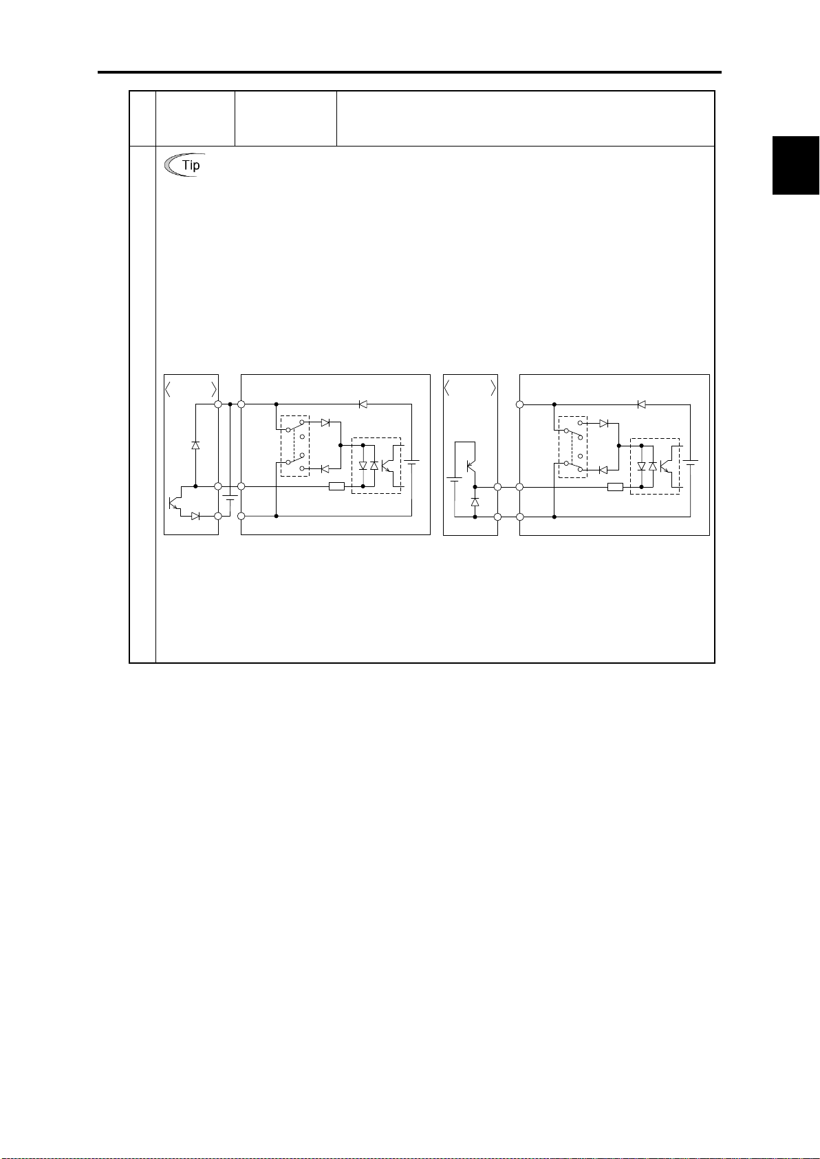
Chap. 2
SPECIFICATIONS
Classifi-
cation
(PLC) to turn control signal input [X1] to [X7], [FWD], or [REV] ON or OFF. In
in the PLC using an external power supply turns ON or OFF control signal [X1] to
Connect the + node of the external power supply (which should be isolated from
[PLC]
Photocoupler
[CM]
<Control circuit>
[X1] to [X7],
[FWD], [REV]
+24 VDC
Programmable
logi c controll er
SOURCE
SINK
[PLC]
Photocoupler
[CM]
<Control circuit>
[X1] to [X7],
[FWD], [REV]
+24 VDC
Programmable
logi c controll er
SOURCE
SINK
2.3 Terminal Specifications
Symbol Name Functions
Using a programmable logic controller (PLC) to turn [X1] to [X7], [FWD], or
[REV] ON or OFF
Figure 2.7 shows two examples of a circuit that uses a programmable logic controller
circuit (a), the slide switch SW1 is turned to SINK, whereas in circuit (b) it is turned
to SOURCE.
In circuit (a) below, short-circuiting or opening the transistor's open collector circuit
[X7], [FWD], or [REV]. When using this type of circuit, observe the following:
the PLC's power) to terminal [PLC] of the inverter.
- Do not connect terminal [CM] of the inverter to the common terminal of the PLC.
Digital input
(a) With the switch turned to SINK (b) With the switch turned to SOURCE
Figure 2.7 Circuit Configuration Using a PLC
For details about the slide switch setting, refer to Section 2.3.2 "Setting up the slide
switches.")
2-21
Page 55

Classifi-
cation
by the slide switch (SW4/SW6) on the control PCB and the
Output form
DC voltage
DC current
SW4
VO1
IO1
F29 0 1
SW6
VO2
IO2
F32 0 1
Analog output, transistor output, and relay output terminals
Symbol Name Functions
[FM1] Analog monitor
[FM2]
Analog output
These terminals output monitor signals of analog DC voltage (0
to +10 V) or analog DC current (+4 to +20 mA DC or 0 to +20
mA DC).
The output form (VO/IO) for [FM1] or [FM2] can be switched
function code F29/F32, as listed below.
Terminal
FM1
FM2
Function
Signal function
specified by
F31 data
F35 data
The signal function can be selected from the following with
function code F31/F35.
• Output frequency • Output current • Output voltage
• Output torque • Load factor • Input power
• PID feedback amount • DC link bus voltage
• Universal AO • Motor output
• Calibration • PID command • PID output
• PID deviation • Reference frequency
• Customizable logic output signal
• Inverter heat sink temperature
• Reference frequency, etc.
For details, refer to Chapter 6 "FUNCTION CODES."
- Input impedance of external device: Min. 5kΩ (at 0 to 10 VDC
output)
(While the terminal is outputting 0 to 10 VDC, it is capable of
driving up to two analog voltmeters with 10 kΩ impedance.)
- Input impedance of external device: Max. 500Ω (at 4 to 20 mA
DC output)
- Adjustable range of the gain: 0 to 300%
[11] Analog common
Two common terminals for analog input and output signals.
These terminals are electrically isolated from terminals [CM]s
and [CMY].
2-22
Page 56

Chap. 2
SPECIFICATIONS
Classifi-
cation
logic system, for example, OFF is 1 in the negative logic
Photocoupler
<Control circuit>
[Y1]
to
[Y4]
[CMY]
31 to 35 V
Voltage
Current
shows examples of connection between the control
2.3 Terminal Specifications
Symbol Name Functions
[Y1]
[Y2]
[Y3]
[Y4]
Transistor
output 1
Transistor
output 2
Transistor
output 3
Transistor
output 4
(1) Various signals such as inverter running, frequency arrival
and overload early warning can be assigned to terminals [Y1]
to [Y4] by setting function code E20 to E23. Refer to Chapter
6 "FUNCTION CODES" for details.
(2) It is possible to switch the logic value (1/0) for ON/OFF of the
terminals between [Y1] to [Y4], and [CMY]. If the logic value
for ON between [Y1] to [Y4] and [CMY] is 1 in the normal
system and vice versa.
(Transistor output circuit specifications)
Figure 2.8 Transistor Output Circuit
Transistor output
[CMY]
Transistor
output common
Item Max.
Operation
voltage
Maximum motor
current at ON
Leakage current
at OFF
ON level
OFF level
2 V
27 V
50 mA
0.1 mA
Figure 2.9
circuit and a PLC.
• When a transistor output drives a control relay, connect
a surge-absorbing diode across relay’s coil terminals.
• When any equipment or device connected to the
transistor output needs to be supplied with DC power,
feed the power (+24 VDC: allowable range: +22 to
+27 VDC, 200 mA max.) through the [PLC] terminal.
Short-circuit between terminals [CMY] and [CM] in
this case.
Common terminal for transistor output signals
This terminal is electrically isolated from terminals [CM]s and
[11]s.
2-23
Page 57

Classifi-
cation
Figure 2.9 shows two examples of circuit connection between the transistor output of
the inverter’s control circuit and a
serves as a SINK for the control circuit output, whereas in example (b), it serves as a
SOURCE for the output.
C0
+24 VDC
Programmable
logic controller
SINK input
Photocoupler
<Control circuit>
[Y1]
to
[Y4]
[CMY]
31 to
35 V
Current
C0
Programmable
logic controller
SOURCE input
+24 VDC
Photocoupler
<Control circuit>
[Y1]
to
[Y4]
[CMY]
31 to
35 V
Current
purpose
Related
Symbol Name Functions
function
codes
Connecting programmable logic controller (PLC) to terminal [Y1], [Y2], [Y3]
or [Y4]
PLC. In example (a), the input circuit of the PLC
Transistor output
[Y5A/C]
[30A/B/C]
Relay output
(a) PLC serving as SINK (b) PLC serving as SOURCE
Figure 2.9 Connecting PLC to Control Circuit
Generalrelay output
(1) A general-purpose relay contact output usable as well as the
function of the transistor output terminal [Y1], [Y2], [Y3] or
[Y4].
Contact rating: 250 VA C 0.3 A, cos φ = 0.3, 48 VDC, 0.5 A
(2) Switching of the normal/negative logic output is applicable to
the following two contact output modes: "Active ON"
(Terminals [Y5A] and [Y5C] are closed (excited) if the signal
is active.) and "Active OFF" (Terminals [Y5A] and [Y5C] are
opened (non-excited) if the signal is active while they are
normally closed.).
Alarm relay
output
(for any error)
(1) Outputs a contact signal (1C) when the protective function has
been activated to stop the motor.
Contact rating: 250 VA C , 0.3A, cos φ = 0.3, 48 VDC, 0.5A
(2) Any one of output signals assigned to terminals [Y1] to [Y4]
can also be assigned to this relay contact to use it for signal
output.
(3) Switching of the normal/negative logic output is applicable to
the following two contact output modes: "Active ON"
(Terminals [30A] and [30C] are closed (excited) if the signal is
active.) and "Active OFF" (Terminals [30A] and [30C] are
opened (non-excited) if the signal is active while they are
normally closed.).
2-24
Page 58

Chap. 2
SPECIFICATIONS
Classifi-
cation
multipoint protocol between the inverter and a computer or other
supplies the power to the keypad through the pins specified
below. The extension cable for remote operation also uses
wires connected to these pins for supplying the keypad
485 communications cable to control the
inverter through the PC or PLC (Programmable Logic
for the keypad, so do not use those pins for any other
Loader running on the computer supports
editing the function codes, transferring them to the inverter,
running an inverter and monitoring the
• Route the wiring of the control circuit terminals as far from the wiring of the main circuit
•
from the
RS-485 communications port
Connector Name Functions
2.3 Terminal Specifications
DX+/DX/SD
RJ-45
connector
for keypad
connection
Communication
RS-485
communications
port 2
(Terminal block)
RS-485
communications
port 1
(Standard RJ-45
connector)
The communications port transmits data through the RS-485
equipment such as a PLC (Programmable Logic Controller).
(For setting of the terminating resistor, refer to Section 2.3.2
"Setting up the slide switches.")
(1) Used to connect the inverter with the keypad. The inverter
power.
(2) Remove the keypad from the standard RJ-45 connector and
connect the RS-
Controller). For setting of the terminating resistor, refer to
Section 2.3.2 "Setting up the slide switches."
Figure 2.10 RJ-45 Connector and its Pin Assignment*
CN10 USB port
CN11
Battery
Connector for
battery
as possible. Otherwise electric noise may cause malfunctions.
Fix the control circuit wires with a cable tie inside the inverter to keep them away
live parts of the main circuit (such as the terminal block of the main circuit).
* Pins 1, 2, 7, and 8 are exclusively assigned to power lines
equipment.
A USB port connector (mini B) that connects an inverter to a
computer. FRENIC
verifying them, testinverter running status.
A connector for an optional battery.
2-25
Page 59

Switches the output mode of the analog output terminal [FM1]/[FM2] between voltage
Output mode
Output mode
2.3.2 Setting up the slide switches
Before changing the switches, turn OFF the power and wait at least ten minutes. Make sure that the LCD
monitor is turned OFF. Further, make sure, using a multimeter or a similar instrument, that the DC link
bus voltage between the terminals P(+) and N(-) has dropped to the safe level (+25 VDC or below).
An electric shock may result if this warning is not heeded as there may be some residual electric
charge in the DC bus capacitor even after the power has been turned OFF.
Switching the slide switches located on the control PCB allows you to customize the operation mode
of the analog output terminals, digital I/O terminals, and communications ports. The locations of those
switches are shown in Figure 2.11.
To access the slide switches, remove the front cover so that you can see the control PCB.
Table 2.1 lists the function of each slide switch.
Table 2.1 Function of Each Slide Switch
Slide Switch Function
SW1
SW2
SW3
SW4/SW6
Switches the service mode of the digital input terminals between SINK and SOURCE.
- This switches the input mode of digital input terminals [X1] to [X7], [FWD] and
[REV] to be used as the SINK or SOURCE mode.
- Factory default: SINK
Switches the terminating resistor of RS-485 communications port on the inverter ON
and OFF. (RS-485 communications port 2, on the terminal block)
- If the inverter is connected to the RS-485 communications network as a terminating
device, turn SW2 to ON.
Switches the terminating resistor of RS-485 communications port on the inverter ON
and OFF. (RS-485 communications port 1, for connecting the keypad)
- To connect a keypad to the inverter, turn SW3 to OFF (Factory default).
- If the inverter is connected to the RS-485 communications network as a terminating
device, turn SW3 to ON.
and current.
When changing this switch setting, also change the data of function code F29/F32.
[FM1] [FM2]
SW4 F29 data SW6 F32 data
Voltage output (Factory default) VO1 0 VO2 0
Current output IO1 1, 2 IO2 1, 2
SW5
Switches the property of the analog input terminal [C1] between analog setting current
input and PTC thermistor input.
When changing this switch setting, also change the data of function code H26.
Analog setting current input
(Factory default)
PTC thermistor input PTC 1 (alarm) or 2 (warning)
2-26
SW5 H26 data
C1 0
Page 60

Chap. 2
SPECIFICATIONS
Figure
To move a switch slider, use a tool with a narrow tip (e.g., tweezers), taking care not to touch
other electronic parts on the PCB. If the slider is in an ambiguous position, the circuit is
unclear whether it is turned ON or OFF and the input remains in an undefined state. Be sure
to place the slider so that it contacts either side of the switch.
Figure 2.11 shows the location of slide switches on the control PCB.
Switching examples and factory default
SW1 SW2 SW3 SW4/SW6 SW5
Shipping
destination
FRNAR1
-2U/4U/5U
2. 11 Location of the Slide Switches
on the Control PCB
SINK
2.3 Terminal Specifications
OFF
OFF
VO1/VO2
C1
Slider in the correct position
Slider in an ambiguous position
or
2-27
Page 61

Tightening
Figure
2.3.3 Screw specifications and recommended wire sizes
2.3.3.1 Main circuit terminals
The specifications of the screws to use for the wiring of the main circuit are shown below. Please note
that terminal arrangements vary depending on inverter capacities.
Refer to 「Chapter 11 CONFORMITY WITH STANDARDS」for recommended wire size.
Use crimp terminals covered with an insulation sheath or with an insulation tube.
Screw Specifications (230 V class series)
Aux. control
power supply
Aux. main circuit
power supply
Screw
size
M3.5 10.6
Power
supply
voltage
Three-
phase
230V
Nominal
applied
motor
(HP)
1 FRN001AR1-2U
2 FRN002AR1-2U
3 FRN003AR1-2U
5 FRN005AR1-2U
7.5 FRN007AR1-2U
10 FRN010AR1-2U
15 FRN015AR1-2U
20 FRN020AR1-2U
25 FRN025AR1-2U
30 FRN030AR1-2U
40 FRN040AR1-2U
50 FRN050AR1-2U
60 FRN060AR1-2U
75 FRN075AR1S-2U
100 FRN100AR1S-2U
125 FRN125AR1S-2U
Inverter type
Refer
to:
A
Figure
B
Figure
C
Figure
D
Figure
E
Figure
F
Figure
L
Main circuit
terminals
Screw
size
M4 15.9 M4 15.9
M6 51.3 M6 51.3
M8
M10 238.9
M12 424.7 M10 238.9
torque
(lb-in)
119.4 M8 119.4
Grounding
terminals
Tightening
Screw
size
M10 238.9
M8 119.4
torque
(lb-in)
Tightening
torque
(lb-in)
Note: A box () replaces an alphabetic letter depending on the enclosure.
M (NEMA/UL TYPE 1) or L (NEMA/UL TYPE 12)
2-28
Page 62

Chap. 2
SPECIFICATIONS
2.3 Terminal Specifications
Screw Specifications (460 V class series)
Aux. control
power supply
Aux. main circuit
power supply
Tightening
Screw
size
M3.5 10.6
torque
(lb-in)
Power
supply
voltage
Three-
phase
460V
Nominal
applied
motor
(HP)
1 FRN001AR1-4U
2 FRN002AR1-4U
3 FRN003AR1-4U
5 FRN005AR1-4U
7.5 FRN007AR1-4U
10 FRN010AR1-4U
15 FRN015AR1-4U
20 FRN020AR1-4U
25 FRN025AR1-4U
30 FRN030AR1-4U
40 FRN040AR1-4U
50 FRN050AR1-4U
60 FRN060AR1-4U
75 FRN075AR1-4U
100 FRN100AR1-4U
125 FRN125AR1-4U
150 FRN150AR1S-4U
200 FRN200AR1S-4U
250 FRN250AR1S-4U
300 FRN300AR1S-4U
350 FRN350AR1S-4U
450 FRN450AR1S-4U
500 FRN500AR1S-4U
600 FRN600AR1S-4U
800 FRN800AR1S-4U
900 FRN900AR1S-4U
1000 FRN1000AR1S-4U
Inverter type
Refer
to:
Figure
A
Figure
B
Figure
C
Figure
D
Figure
E
Figure
F
Figure
G
Figure
H
Figure
I
Figure
J
Figure
K
Main circuit
terminals
Screw
Tightening
size
M4 15.9 M4 15.9
M6 51.3 M6 51.3
M6 51.3 M6 51.3
M8 119.4 M8 119.4
M10 238.9
M12 424.7 M10 238.9
torque
(lb-in)
Grounding
terminals
Tightening
Screw
size
M10 238.9
M8 119.4
torque
(lb-in)
Note: A box () replaces an alphabetic letter depending on the enclosure.
M (NEMA/UL TYPE 1) or L (NEMA/UL TYPE 12)
2-29
Page 63

Screw Specifications (575 V class series)
Power
supply
voltage
Nominal
applied
motor
(HP)
Inverter type
Refer
to:
Screw
size
1 FRN001AR1-5U
2 FRN002AR1-5U
3 FRN003AR1-5U
5 FRN005AR1-5U
Figure
A
M4 15.9 M4 15.9
7.5 FRN007AR1-5U
10 FRN010AR1-5U
15 FRN015AR1-5U
Three-
phase
575V
20 FRN020AR1-5U
25 FRN025AR1-5U
30 FRN030AR1-5U
40 FRN040AR1-5U
50 FRN050AR1-5U
60 FRN060AR1-5U
75 FRN075AR1-5U
Figure
B
Figure
C
Figure
D
M6 51.3 M6 51.3
M6 51.3 M6 51.3
M8 119.4 M8 119.4
100 FRN100AR1-5U
125 FRN125AR1-5U
Figure
E
M10 238.9 M10 238.9
150 FRN150AR1-5U
200 FRN200AR1S-5U
250 FRN250AR1S-5U
Figure
G
M12 424.7 M10 238.9
300 FRN300AR1S-5U
Note: A box () replaces an alphabetic letter depending on the enclosure.
M (NEMA/UL TYPE 1) or L (NEMA/UL TYPE 12)
Main circuit
terminals
Tightening
torque
(lb-in)
Grounding
terminals
Screw
size
Tightening
torque
(lb-in)
Aux. control
power supply
Aux. main circuit
power supply
size
Tightening
torque
(lb-in)
Screw
M3.5 10.6
2-30
Page 64

Chap. 2
SPECIFICATIONS
Figure A
Figure B
Figure C
2.3 Terminal Specifications
When the inverter power is ON, a high voltage is applied to the following terminals.
Main circuit terminals: L1/R, L2/S, L3/T, P(+), N(-), U, V, W, R0, T0, R1, T1, AUX-contact (30A, 30B, 30C, Y5A, Y5C)
Insulation level
Main circuit-Enclosure : Basic insulation (Overvoltage category III, Pollution degree 2)
Main circuit-Control circuit : Reinforced insulation (Overvoltage category III, Pollution degree 2)
Relay output-Control circuit : Reinforced insulation (Overvoltage category II, Pollution degree 2)
An electric shock may occur.
Terminal Arrangement Diagrams
Unit: mm (inch)
(NC): No connection (Do not make wiring.)
2-31
Page 65

Figure D
Figure E
Unit: mm (inch)
(NC): No connection (Do not make wiring.)
2-32
Page 66

Chap. 2
SPECIFICATIONS
Figure F
Figure G/
Figure H
Figure I
2.3 Terminal Specifications
Unit: mm (inch)
2-33
Page 67
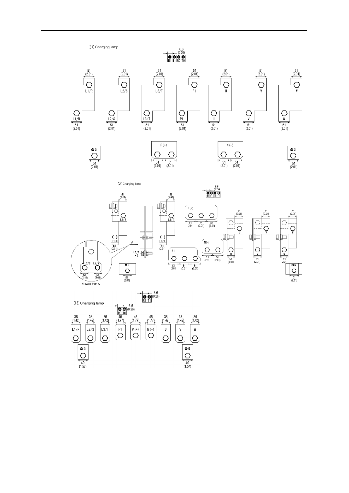
Figure J
Figure K
Figure L
Unit: mm (inch)
2-34
Page 68

Chap. 2
SPECIFICATIONS
Screw type
2.3 Terminal Specifications
2.3.3.2 Control circuit terminals (Common to all inverter types)
The control circuit terminal arrangement, screw sizes, and tightening torque are shown below.
The control circuit terminals are common to all inverter types regardless of their capacities.
Screw type of terminal block
Table 2.2 Control Circuit Terminals
Screw specifications
Terminal
block type
Screw
size
M3
Tightening
torque
0.7 N·m
(6.2 lb-in)
Recommended
wire size (mm2)
AWG 1 8
(0.75 mm
2
)
2-35
Page 69

Punch-out #
*1
Punch-out #
*1
Punch-out #
*1
2.4 Conduits
To ensure NEMA/UL Type 12 rating, mount conduits on the wiring plate in wiring. The conduits
should be selected according to the number of wires to be connected and the wire size.
Sections 2.4.1 give the sizes of the conduits to be applied when the wires of the recommended sizes are
used. Their sizes and mounting positions differ depending upon the inverter capacity.
2.4.1 Conduits
The tables given below list examples of recommended conduits. Use the equivalents.
(1) FRN001AR1■-2U to FRN005AR1■-2U and FRN001AR1■-4U/5U to FRN010AR1■-4U/5U
(See Figure A.)
Conduit body
in wiring
plate
1 LT75P 3/4 142 3/4 For inverter output *2
2 LT50P 1/2 141 1/2 For connection to the DC link bus
3 LT75P 3/4 142 3/4
4 LT125P 1 1/4 144 1 1/4 For wiring to the control terminal block
5 LT75P 3/4 142 3/4 For wiring to option cards, etc.
*1 Manufacturer: Thomas & Betts (T & B)
*2 Prepunched
BULLET
models
Nut *1
Size (inch)
Locknut
models
Size (inch)
Recommended wiring examples
For main power input and auxiliary
input of control power *2
(2) FRN007AR1■-2U to FRN015AR1■-2U and FRN015AR1■-4U/5U to FRN030AR1■-4U/5U
(See Figure B.)
Conduit body
in wiring
plate
1 LT125P 1 1/4 144 1 1/4 For inverter output *2
2 LT100P 1 143 1 For connection to the DC link bus
3 LT100P 1 143 1
4 LT125P 1 1/4 144 1 1/4 For wiring to the control terminal block
5 LT75P 3/4 142 3/4 For wiring to option cards, etc.
*1 Manufacturer: Thomas & Betts (T & B)
*2 Prepunched
BULLET
models
Nut *1
Size (inch)
Locknut
models
Size (inch)
Recommended wiring examples
For main power input and auxiliary
input of control power *2
(3) FRN020AR1■-2U, FRN025AR1■-2U, FRN040AR1■-4U/5U, and FRN050AR1■-4U/5U
(See Figure C.)
Conduit body
in wiring
plate
1 LT200P 2 146 2 For inverter output *2
2 LT100P 1 143 1 For connection to the DC link bus
3 LT125P 1 1/4 144 1 1/4
4 LT125P 1 1/4 144 1 1/4 For wiring to the control terminal block
5 LT75P 3/4 142 3/4 For wiring to option cards, etc.
*1 Manufacturer: Thomas & Betts (T & B)
*2 Prepunched
BULLET
models
Nut *1
Size (inch)
Locknut
models
2-36
Size (inch)
Recommended wiring examples
For main power input and auxiliary
input of control power *2
Page 70

Chap. 2
SPECIFICATIONS
Punch-out #
*1
Punch-out #
*1
(4) FRN030AR1■-2U, FRN040AR1■-2U, FRN060AR1■-4U, and FRN075AR1■-4U/5U
(See Figure D.)
2.4 Conduits
Conduit body
in wiring
plate
1 H200-TB 2
2 H125-TB 1 1/4 For connection to the DC link bus
3 H150-TB 1 1/2
4 H125-TB 1 1/4 For wiring to the control terminal block
5 H75-TB 3/4 For wiring to option cards, etc.
*1 Manufacturer: Thomas & Betts (T & B)
*2 Prepunched
BULLET
models
Nut *1
Size (inch)
Locknut
models
Integrated in conduit body
Size (inch)
Recommended wiring examples
For inverter output *2
For main power input and auxiliary
input of control power *2
(5) FRN050AR1■-2U, FRN060AR1■-2U, FRN100AR1■-4U, and FRN125AR1■-4U
FRN100AR1■-/5U to FRN150AR1■5U
(See Figure E.)
Conduit body
in wiring
plate
1 H300-TB 3
2 H200-TB 2 For connection to the DC link bus
3 H250-TB 2 1/2
4 H125-TB 1 1/4 For wiring to the control terminal block
5 H75-TB 3/4 For wiring to option cards, etc.
*1 Manufacturer: Thomas & Betts (T & B)
*2 Prepunched
BULLET
models
Nut *1
Size (inch)
Locknut
models
Integrated in conduit body
Size (inch)
Recommended wiring examples
For inverter output *2
For main power input and auxiliary
input of control power *2
2-37
Page 71

Figure A
Figure B
Figure C
Figure D
Figure E
Punch-out Arrangement in Wiring Plate
For instructions on how to punch out semi-perforated sections in the wiring plate and set
conduits on the wiring plate, refer to Chapter 5, Section 5.1.2.1 "(2) Punching out
semi-perforated sections in the wiring plate and setting conduits."
2-38
Page 72
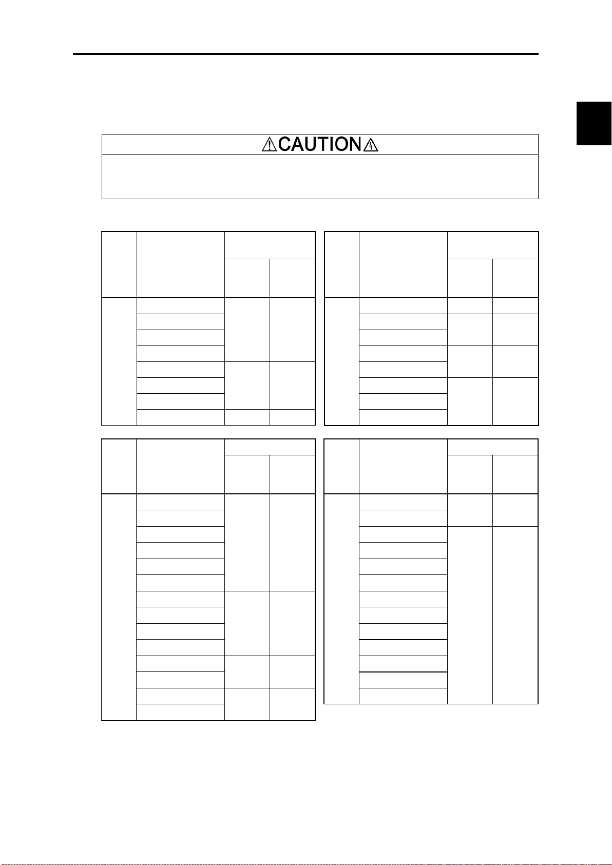
Chap. 2
SPECIFICATIONS
case
case
case
case
2.5 Leakage Current of the EMC Filter
2.5 Leakage Current of the EMC Filter
This product uses grounding capacitors for noise suppression which increase the leakage current.
Check whether there is no problem with power supply systems.
As the leakage current of the EMC filter is relatively high, it is important to always assure a reliable
connection to Protection Earth (PE).
An electric shock may occur.
Table 2.3 Leakage Current of EMC Filter
Input
power
Three-
phase
230 V
*1
Leakage current
(mA)
Inverter type
FRN001AR1-2U
FRN002AR1-2U FRN030AR1-2U
FRN003AR1-2U FRN040AR1-2U
FRN005AR1-2U FRN050AR1-2U
FRN007AR1-2U
FRN010AR1-2U FRN075AR1S-2U
FRN015AR1-2U FRN100AR1S-2U
FRN020AR1-2U 180 291 FRN125AR1S-2U
Under
normal
conditions
86 140
224 357
Under
worstconditions
Input
power
Inverter type
FRN025AR1-2U 180 291
Three-
phase
230 V
FRN060AR1-2U
*1
Leakage current
(mA)
Under
normal
conditions
198 314
204 322
worstconditions
18 23
Under
Leakage current (mA)
Input
power
Three-
phase
460 V
*2
Inverter type
FRN001AR1-4U
FRN002AR1-4U FRN125AR1-4U
FRN003AR1-4U FRN150AR1S-4U
FRN005AR1-4U FRN200AR1S-4U
FRN007AR1-4U FRN250AR1S-4U
FRN010AR1-4U FRN300AR1S-4U
FRN015AR1-4U
FRN020AR1-4U FRN450AR1S-4U
FRN025AR1-4U FRN500AR1S-4U
FRN030AR1-4U FRN600AR1S-4U
FRN040AR1-4U
FRN050AR1-4U FRN900AR1S-4U
FRN060AR1-4U
FRN075AR1-4U
Under
normal
conditions
55 164
135 417
111 381
119 367
Under
worstconditions
Input
power
Three-
phase
460 V
*2
FRN800AR1S-4U
FRN1000AR1S-4U
Inverter type
FRN100AR1-4U
FRN350AR1S-4U
Leakage current (mA)
Under
normal
conditions
148 440
3 34
Under
worst-
conditions
*1 Calculated based on these measuring conditions: 200 V/ 50 Hz, grounding of a single wire in
delta-connection, interphase voltage unbalance ratio 2%.
*2 Calculated based on these measuring conditions: 400 V/ 50 Hz, neutral grounding in Y-connection,
interphase voltage unbalance ratio 2%.
Note The worst-case conditions include input phase loss.
2-39
Page 73

case
case
Table 2.3 Leakage Current of EMC Filter(continue)
Leakage current (mA)
Input
power
Inverter type
FRN001AR1-5U
Under
normal
conditions
Under
worst-
conditions
Input
power
Inverter type
FRN040AR1-5U
FRN002AR1-5U FRN050AR1-5U
Three-
phase
575 V
*3
FRN003AR1-5U FRN060AR1-5U
FRN005AR1-5U FRN075AR1-5U
FRN007AR1-5U FRN100AR1-5U
FRN010AR1-5U FRN125AR1-5U
FRN015AR1-5U
FRN020AR1-5U FRN200AR1S-5U
FRN025AR1-5U FRN250AR1S-5U
68 119
34 113
Three-
phase
575 V
*3
FRN150AR1-5U
FRN030AR1-5U FRN300AR1S-5U
*3 Calculated based on these measuring conditions: 575 V/ 60 Hz, neutral grounding in Y-connection,
interphase voltage unbalance ratio 2%.
Note The worst-case conditions include input phase loss.
Leakage current (mA)
Under
normal
conditions
Under
worstconditions
56 149
98 375
108 393
18 79
2-40
Page 74

Chap. 2
SPECIFICATIONS
[E1]
[E2]
Usually there is no need to do anything for the EMC filter.
When the leakage current from the connected EMC filter causes problems with the power
supply system, removing screws from terminals [E1] and [E2] could improve the problem.
Note that doing so loses the effect of the EMC filter so that the inverter is no longer compliant
with the EMC standards. To remove those screws, consult your Fuji Electric representative.
For
, see the arrangement of terminals given in Section
2.3.3.1.
The 2
or
above have neither [E1] nor [E2]. If you need to separate the EMC filter from those inverters,
consult your Fuji Electric representative.
Filter
Supports
2.5 Leakage Current of the EMC Filter
the location of terminals [E1] and [E2]
30 V class series inverters of 75 HP or above and 460 V / 575 V ones of 150 HP
FRN001AR1-2U to FRN025AR1-2U, FRN001AR1-4U/5U to FRN050AR1-4U/5U
Removing the screws from terminals [E1] and [E2] separates the grounding capacitors, decreasing
the leakage current.
FRN030AR1-2U to FRN060AR1-2U, FRN060AR1-4U to FRN125AR1-4U
FRN060AR1-5U to FRN150AR1-5U
Secure the filter grounding wires to the supports, using the screws removed from terminals [E1] and
[E2].
grounding
wires
2-41
Page 75

,
,
2.6 Derating of Rated Output Current
When increasing the carrier frequency setting (Function code F26) greater than the factory default 2
kHz, you need to derate the output current rating. Derating allows the higher ambient temperature than
the rating. The tables below list the derating factors in relation to the carrier frequency and ambient
temperature. Use the inverters within the range specified below.
(1) NEMA/UL TYPE1 : FRN001AR1M-2U to FRN060AR1M-2U
FRN125AR1M-4U
NEMA/UL TYPE 12: FRN001AR1L-2U to FRN060AR1L-2U
FRN125AR1L-4U
Output current derating factor (rated current ratio)
Carrier
frequency
setting
(kHz)
NEMA/
UL TYPE1
50°C
(122°F)
NEMA/
UL TYPE1
60°C
(140°F)
NEMA/
UL TYPE12
40°C
(104°F)
NEMA/UL TYPE12, 50°C (122°F)
Group 1 Group 2 Group 3 Group 4
0.75 to 2 100% 50% 100% 90% 80% 75% 70%
3 100% 50% 100% 90% 80% 75% 70%
4 93% 47% 93% 84% 74% 70% 65%
5 87% 44% 87% 78% 70% 65% 61%
6 81% 41% 81% 73% 65% 61% 57%
7 76% 38% 76% 68% 61% 57% 53%
8 72% 36% 72% 65% 58% 54% 50%
9 68% 34% 68% 61% 54% 51% 48%
10 64% 32% 64% 58% 51% 48% 45%
11 60% 30% 60% 54% 48% 45% 42%
12 57% 29% 57% 51% 46% 43% 40%
13 55% 28% 55% 50% 44% 41% 39%
14 52% 26% 52% 47% 42% 39% 36%
15 50% 25% 50% 45% 40% 38% 35%
16 47% 24% 47% 42% 38% 35% 33%
FRN001AR1M-4U to
FRN001AR1L-4U to
Note: For 230 V class series inverters of 30 to 100 HP and 460 V ones of 60 to 125 HP, the upper limit
of the carrier frequency is 10 kHz.
Group 1
Group 2
Group 3
Group 4
Note: About FRN030AR1L-2U to FRN060AR1L-2U, consult your Fuji Electric representative.
230V class series: FRN001AR1L-2U, FRN003AR1L-2U
460V class series: FRN001AR1L-4U, FRN002AR1L-4U, FRN003AR1L-4U, FRN007AR1L-4U
230V class series: FRN005AR1L-2U, FRN007AR1L-2U, FRN010AR1L-2U
460V class series: FRN010AR1L-4U, FRN020AR1L-4U, FRN100AR1L-4U, FRN125AR1L-4U
230V class series: FRN002AR1L-2U, FRN015AR1L-2U
460V class series: FRN005AR1L-4U, FRN015AR1L-4U, FRN025AR1L-4U,
FRN030AR1L-4U, FRN060AR1L-4U, FRN075AR1L-4U
230V class series: FRN020AR1L-2U, FRN025AR1L-2U
460V class series: FRN040AR1L-4U, FRN050AR1L-4U
Contact Fuji Electric for details on 575V class series derating curves.
2-42
Page 76

Chap. 2
SPECIFICATIONS
(2) Open type: FRN075AR1S-2U, FRN100AR1S-2U
2.6 Derating of Rated Output Current
Carrier frequency
setting (kHz)
0.75 to 2 100% 100%
3 100% 100%
4 100% 100%
5 100% 100%
6 100% 100%
7 100% 95%
8 100% 90%
9 100% 85%
10 100% 80%
Output current derating factor (rated current ratio)
Ambient temperature
40°C(104°F)
(3) Open type: FRN125AR1S-2U
Carrier frequency
setting (kHz)
0.75 to 2 100% 100%
3 100% 100%
4 100% 100%
5 100% 95%
6 100% 85%
Output current derating factor (rated current ratio)
Ambient temperature
40°C(104°F)
Ambient temperature
50°C(122°F)
Ambient temperature
50°C(122°F)
(4) Open type: FRN150AR1S-4U to
Carrier frequency
setting (kHz)
0.75 to 2 100% 100%
3 100% 100%
4 100% 100%
5 100% 90%
6 100% 80%
Output current derating factor (rated current ratio)
Ambient temperature
FRN1000AR1S-4U
40°C(104°F)
Ambient temperature
50°C(122°F)
Note: For 460 V class series inverters of 1000 HP, the upper limit of the carrier frequency is 4 kHz.
2-43
Page 77

The inverter must not be subjected to sudden changes in temperature that will cause
2.7 Operating Environment and Storage Environment
2.7.1 Operating environment
Install the inverter in an environment that satisfies the requirements listed below.
Table 2.4 Environmental Requirements
Item Specifications
Site location
Ambient
temperature
Indoors
NEMA/UL TYPE 1
-10 to +50°C (14 to 122°F)
(-10 to +40°C (14 to 104°F) for inverters mounted closely side by side*)
+50 to +60°C (122 to 140°F) (when current derating )
NEMA/UL TYPE 12
-10 to +40°C (14 to 104°F)
(-10 to +30°C for inverters mounted closely side by side*)
+40 to +50°C (104 to 122°F) (when current derating )
UL open type
-10 to +50°C (14 to 122°F)
* The 230 V class series inverters of 25 HP or below and 460 V / 575 V ones of 50
HP or below can be mounted closely side by side.
Relative humidity 5 to 95% (No condensation)
Atmosphere
The inverter must not be exposed to dusts, direct sunlight, corrosive or flammable
gases, oil mist, vapor or water drops.
Pollution degree 2 (IEC/EN 60664-1)
The atmosphere can contain a small amount of salt.
2
(0.01 mg/cm
or less per year)
condensation to form.
Altitude 1000 m (3300 ft) max. (Note 2)
(Note 1)
Atmospheric
86 to 106 kPa
pressure
Vibration
230 V 60 HP or below
460 V 125 HP or below
575 V 150 HP or below
3 mm (0.12 inch): 2 to less
than 9 Hz
2
: 9 to less than 200 Hz
10 m/s
230 V 75 HP 100HP
3 mm (0.12 inch): 2 to less
than 9 Hz
9.8 m/s2: 9 to less than 20 Hz
2
: 20 to less than 55 Hz
2 m/s
1 m/s2: 55 to less than 200 Hz
230 V 125HP
460 V 150 to 1000 HP
575 V 200 to 300 HP
3 mm (0.12 inch): 2 to less
than 9 Hz
2
: 9 to less than 55 Hz
2 m/s
1 m/s2: 55 to less than 200 Hz
(Note 1) Do not install the inverter in an environment where it may be exposed to cotton waste or moist dust or
dirt which will clog the heat sink in the inverter. If the inverter is to be used in such an environment,
install it in the panel of your system or other dustproof containers.
(Note 2) If you use the inverter in an altitude above 1000 m (3300 ft), you should apply an output current
derating factor as listed in Table 2.5.
Table 2.5 Output Current Derating Factor in Relation to Altitude
Altitude Output current derating factor
1000 m (3300 ft) or lower 1.00
1000 to 1500 m (3300 to 4900 ft) 0.97
1500 to 2000 m (4900 to 6600 ft) 0.95
2000 to 2500 m (6600 to 8200 ft) 0.91
2500 to 3000 m (8200 to 9800 ft) 0.88
2-44
Page 78

Chap. 2
SPECIFICATIONS
, direct sunlight, corrosive or flammable
2.7 Operating Environment and Storage Environment
2.7.2 Storage environment
2.7.2.1 Temporary storage
Store the inverter in an environment that satisfies the requirements listed below.
Table 2.6 Storage and Transport Environments
Item Specifications
Storage
temperature
Relative
humidity
Atmosphere
Atmospheric
pressure
-25 to +70°C (-13 to +158°F)
1
*
5 to 95%
The inverter must not be exposed to dusts
gases, oil mist, vapor, water drops or vibration. The atmosphere must contain only a low
level of salt. (0.01 mg/cm
86 to 106 kPa (during storage)
70 to 106 kPa (during transportation)
*1 Assuming comparatively short time storage, e.g., during transportation or the like.
*2 Even if the humidity is within the specified requirements, avoid such places where the inverter
will be subjected to sudden changes in temperature that will cause condensation to form.
2
*
Places not subjected to abrupt temperature changes or
condensation or freezing
2
or less per year)
Precautions for temporary storage
(1) Do not leave the inverter directly on the floor.
(2) If the environment does not satisfy the specified requirements listed in Table 2.6 wrap the
inverter in an airtight vinyl sheet or the like for storage.
(3) If the inverter is to be stored in a high-humidity environment, put a drying agent (such as silica
gel) in the airtight package described in item (2).
2.7.2.2 Long-term storage
The long-term storage method of the inverter varies largely according to the environment of the
storage site. General storage methods are described below.
(1) The storage site must satisfy the requirements specified for temporary storage.
However, for storage exceeding three months, the ambient temperature range should be within the
range from -10 to 30°C (14 to 86°F). This is to prevent electrolytic capacitors in the inverter from
deterioration.
(2) The package must be airtight to protect the inverter from moisture. Add a drying agent inside the
package to maintain the relative humidity inside the package within 70%.
(3) If the inverter has been installed to the equipment or panel at construction sites where it may be
subjected to humidity, dust or dirt, then temporarily remove the inverter and store it in the
environment specified in Table 2.6.
Precautions for storage over 1 year
If the inverter has not been powered on for a long time, the property of the electrolytic capacitors may
deteriorate. Power the inverters on once a year and keep the inverters powering on for 30 to 60 minutes.
Do not connect the inverters to the load circuit (secondary side) or run the inverter.
2-45
Page 79

influence of the gases.
In an environment where a
2.8 Precautions for Using Inverters
2.8.1 Precautions in introducing inverters
This section provides precautions in introducing inverters, e.g. precautions for installation
environment, power supply lines, wiring, and connection to peripheral equipment. Be sure to observe
those precautions.
Installation environment
Install the inverter in an environment that satisfies the requirements listed in Table 2.4 in Section 2.7.1.
Fuji Electric strongly recommends installing inverters in a panel for safety reasons, in particular, when
installing the ones whose enclosure rating is UL open type.
When installing the inverter in a place out of the specified environmental requirements, it is necessary
to derate the inverter or consider the panel engineering suitable for the special environment or the
panel installation location.
The special environments listed below require using the specially designed panel or considering the
panel installation location
Unusual
environments
Highly concentrated
sulfidizing gas or
other corrosive gases
A lot of conductive
dust or foreign
material (e.g., metal
powders or shavings,
carbon fibers, or
carbon dust)
A lot of fibrous or
paper dust
High humidity or
dew condensation
Vibration or shock
exceeding the
specified level
Possible problems Sample measures Remarks
Corrosive gases cause parts
inside the inverter to
corrode, resulting in an
inverter malfunction.
Entry of conductive dust
into the inverter causes a
short circuit.
Fibrous or paper dust
accumulated on the heat
sink lowers the cooing
effect.
Entry of dust into the
inverter causes the
electronic circuitry to
malfunction.
humidifier is used or where
the air conditioner is not
equipped with a
dehumidifier, high
humidity or dew
condensation results, which
causes a short-circuiting or
malfunction of electronic
circuitry inside the inverter.
If a large vibration or shock
exceeding the specified
level is applied to the
inverter, for example, due to
a carrier running on seam
joints of rails or blasting at a
construction site, the
inverter structure gets
damaged.
Any of the following measures may be
necessary.
- Mount the inverter in a sealed panel with
IP6X or air-purge mechanism.
- Place the panel in a room free from
Any of the following measures may be
necessary.
- Mount the inverter in a sealed panel.
- Place the panel in a room free from
influence of the conductive dust.
Any of the following measures may be
necessary.
- Mount the inverter in a sealed panel that
shuts out dust.
- Ensure a maintenance space for
periodical cleaning of the heat sink in
panel engineering design.
- Employ external cooling when mounting
the inverter in a panel for easy
maintenance and perform periodical
maintenance.
- Put a heating module such as a space
heater in the panel.
- Insert shock-absorbing materials
between the mounting base of the
inverter and the panel for safe mounting.
2-46
Page 80

Chap. 2
SPECIFICATIONS
MotorInverter
Power
input
Max. 50 m
Max. 100 m
Inverter
Motor
Max. 5 m
Max. 400 m
Output circuit filter
Power
input
2.8 Precautions for Using Inverters
Unusual
environments
Fumigation for
export packaging
Possible problems Sample measures Remarks
Halogen compounds such
as methyl bromide used in
fumigation corrodes some
parts inside the inverter.
- When exporting an inverter built in a
panel or equipment, pack them in a
previously fumigated wooden crate.
- When packing an inverter alone for
export, use a laminated veneer lumber
(LVL).
Exporting.
Wiring precautions
(1) Route the wiring of the control circuit terminals as far from the wiring of the main circuit as
possible. Otherwise electric noise may cause malfunctions.
(2) Fix the control circuit wires with a cable tie inside the inverter to keep them away from the live
parts of the
main circuit (such as the terminal block of the main circuit).
(3) If more than one motor is to be connected to a single inverter, the wiring length should be the
sum of the length of the wires to the motors.
(4) Precautions for high frequency leakage currents
If the wiring distance between an inverter and a motor is long, high frequency currents flowing
through stray capacitance across wires of phases may cause an inverter overheat, overcurrent trip,
increase of leakage current, or it may not assure the accuracy in measuring leakage current.
Depending on the operating condition, an excessive leakage current may damage the inverter.
To avoid the above problems when directly connecting an inverter to a motor, keep the wiring
distance 50 m (165 ft) or less for inverters of 3.7kW (5 HP) or below, and 100 m (328 ft) or less
for inverters of a higher capacity. Output circuit filters cannot be used with the three-phase 575V
class series.
If the wiring distance longer than the specified above is required, lower the carrier frequency or
insert an output circuit filter (OFL--A) as shown below.
When a single inverter drives two or more motors connected in parallel (group drive), in
particular, when using shielded wires, the stray capacitance to the earth is large, so lower the
carrier frequency or insert an output circuit filter (OFL--A).
Output circuit filters cannot
be used with the three-phase 575V class series.
No output circuit filter installed Output circuit filter installed
For an inverter with an output circuit filter installed, the total secondary wiring length should be
400 m (1312 ft) or less.
If further longer secondary wiring is required, consult your Fuji Electric representative.
(5) Precautions for surge voltage in driving a motor by an inverter
If the motor is driven by a PWM-type inverter, surge voltage generated by switching the inverter
component may be superimposed on the output voltage and may be applied to the motor
terminals. Particularly if the wiring length is long, the surge voltage may deteriorate the
insulation resistance of the motor. Implement any of the following measures.
- Use a motor with insulation that withstands the surge voltage. (All Fuji standard motors
feature reinforced insulation.)
- Connect a surge suppressor unit (SSU50/100TA-NS) at the motor terminal.
- Connect an output circuit filter (OFL--A) to the output terminals (secondary circuits)
of the inverter.
- Minimize the wiring length between the inverter and motor (10 to 20 m (33 to 66ft) or less).
2-47
Page 81

67 ×
V)(voltageaveragephase-Three
V)( voltageMin.V)( voltageMax.
=%)(unbalance voltageInterphase
in the upstream power supply line in order to avoid the entire power supply system's shutdown
leakage circuit breaker (ELCB) individually to inverters to break the individual inverter power supply
From the system's safety point of view, it is recommended to employ such a sequence that
shuts down the magnetic contactor (MC) in the inverter input circuit with an alarm output
signal
issued on inverter's programmable output terminals. The sequence minimizes
the secondary damage even if the inverter breaks.
When the sequence is employed, connecting the MC's primary power line to the inverter's
auxiliary control power input makes it possible to monitor the inverter's alarm status on the
keypad.
(6) When an output circuit filter is inserted in the secondary circuit or the wiring between the
inverter and the motor is long, a voltage loss occurs due to reactance of the filter or wiring so that
the insufficient voltage may cause output current oscillation or a lack of motor output torque. To
avoid it, select the constant torque load by setting the function code F37 (Load Selection/Auto
Torque Boost/Auto Energy Saving Operation 1) to "1" and keep the inverter output voltage at a
higher level by configuring H50/H52 (Non-linear V/f Pattern, Frequency) and H51/H53
(Non-linear V/f Pattern, Voltage).
Precautions for connection of peripheral equipment
(1) Power supply lines (Using AC reactor)
If the interphase voltage unbalance ratio of the inverter power supply is 2 to 3%, use an optional
AC reactor (ACR).
(See IEC/EN 61800-3.)
(2) Molded case circuit breaker (MCCB) or residual-current-operated protective device (RCD)/earth
leakage circuit breaker (ELCB)
Install a recommended MCCB or RCD/ELCB (with overcurrent protection) in the primary
circuit of the inverter to protect the wiring. Since using an MCCB or RCD/ELCB with a lager
capacity than recommended ones breaks the protective coordination of the power supply system,
be sure to select recommended ones. Also select ones with short-circuit breaking capacity
suitable for the power source impedance.
If no zero-phase current (earth leakage current) detective device such as a ground-fault relay is installed
undesirable to factory operation, install a residual-current-operated protective device (RCD)/earth
lines only.
Otherwise, a fire could occur.
(3) Magnetic contactor (MC) in the inverter input (primary) circuit
Avoid frequent ON/OFF operation of the magnetic contactor (MC) in the input circuit; otherwise,
the inverter failure may result. If frequent start/stop of the motor is required, use FWD/REV
terminal signals or the / and keys on the inverter's keypad.
The frequency of the MC's ON/OFF should not be more than once per 30 minutes. To assure
5-year or longer service life of the inverter, it should not be more than once per hour.
ALM
(4) Magnetic contactor (MC) in the inverter output (secondary) circuit
If a magnetic contactor (MC) is inserted in the inverter's output (secondary) circuit for switching
the motor to a commercial power or for any other purposes, it should be switched on and off
when both the inverter and motor are completely stopped. This prevents the contact point from
getting rough due to a switching arc of the MC. The MC should not be equipped with any main
circuit surge killer (Fuji SZ-ZM etc.).
Applying a commercial power to the inverter's output circuit breaks the inverter. To avoid it,
interlock the MC on the motor's commercial power line with the one in the inverter output circuit
so that they are not switched ON at the same time.
(5) Surge absorber/surge killer
Do not install any surge absorber or surge killer in the inverter's output (secondary) lines.
2-48
Page 82

Chap. 2
SPECIFICATIONS
2.8 Precautions for Using Inverters
Noise reduction
If noise generated from the inverter affects other devices, or that generated from peripheral equipment
causes the inverter to malfunction, follow the basic measures outlined below.
(1) If noise generated from the inverter affects the other devices through power wires or grounding
wires:
- Isolate the grounding terminals of the inverter from those of the other devices.
- Connect a noise filter to the inverter power wires.
- Isolate the power system of the other devices from that of the inverter with an insulated
transformer.
- Decrease the inverter's carrier frequency (F26).
(2) If induction or radio noise generated from the inverter affects other devices:
- Isolate the main circuit wires from the control circuit wires and other device wires.
- Put the main circuit wires through a metal conduit pipe, and connect the pipe to the ground
near the inverter.
- Install the inverter into the metal panel and connect the whole panel to the ground.
- Connect a noise filter to the inverter's power wires.
- Decrease the inverter's carrier frequency (F26).
(3) When implementing measures against noise generated from peripheral equipment:
- For inverter's control signal wires, use twisted or shielded-twisted wires. When using
shielded-twisted wires, connect the shield of the shielded wires to the common terminals of
the control circuit.
- Connect a surge absorber in parallel with magnetic contactor's coils or other solenoids (if
any).
Leakage current
A high frequency current component generated by insulated gate bipolar transistors (IGBTs)
switching on/off inside the inverter becomes leakage current through stray capacitance of inverter
input and output wires or a motor. If any of the problems listed below occurs, take an appropriate
measure against them.
Problem Measures
An earth leakage circuit
breaker* that is connected
to the input (primary) side
has tripped.
* With overcurrent protection
An external thermal relay
was activated.
1) Decrease the carrier frequency.
2) Make the wires between the inverter and motor shorter.
3) Use an earth leakage circuit breaker with lower sensitivity than the
one currently used.
1) Decrease the carrier frequency.
2) Increase the setting current of the thermal relay.
3) Use the electronic thermal overload protection built in the inverter,
instead of the external thermal relay.
Selecting inverter capacity
(1) To drive a general-purpose motor, select an inverter according to the nominal applied motor
rating listed in the standard specifications table. When high starting torque is required or quick
acceleration or deceleration is required, select an inverter with one rank higher capacity than the
standard.
(2) Special motors may have larger rated current than general-purpose ones. In such a case, select an
inverter that meets the following condition.
Inverter rated current > Motor rated current
2-49
Page 83

2.8.2 Precautions in running inverters
Precautions for running inverters to drive motors or motor-driven machinery are described below.
Motor temperature
When an inverter is used to run a general-purpose motor, the motor temperature becomes higher than
when it is operated with a commercial power supply. In the low-speed range, the motor cooling effect
will be weakened, so decrease the output torque of the motor when running the inverter in the
low-speed range.
Motor noise
When a general-purpose motor is driven by an inverter, the noise level is higher than that when it is
driven by a commercial power supply. To reduce noise, raise the carrier frequency of the inverter.
Operation at 60 Hz or higher can also result in higher noise level.
Machine vibration
When an inverter-driven motor is mounted to a machine, resonance may be caused by the natural
frequencies of the motor-driven machinery. Driving a 2-pole motor at 60 Hz or higher may cause
abnormal vibration. If it happens, do any of the following:
- Consider the use of a rubber coupling or vibration-proof rubber.
- Use the inverter's jump frequency control feature to skip the resonance frequency zone(s).
- Use the vibration suppression related function codes that may be effective. For details, refer to the
description of H80 in Chapter 6 "FUNCTION CODES."
2.8.3 Precautions in using special motors
When using special motors, note the followings.
Submersible motors and pumps
These motors have a larger rated current than general-purpose motors. Select an inverter whose rated
output current is greater than that of the motor. These motors differ from general-purpose motors in
thermal characteristics. Decrease the thermal time constant of the electronic thermal overload
protection to match the motor rating.
Brake motors
For motors equipped with parallel-connected brakes, their power supply for braking must be supplied
from the inverter input (primary) circuit. If the power supply for braking is mistakenly connected to
the inverter's output (secondary) circuit, the brake may not work when the inverter output is shut down.
Do not use inverters for driving motors equipped with series-connected brakes.
Geared motors
If the power transmission mechanism uses an oil-lubricated gearbox or speed changer/reducer, then
continuous operation at low speed may cause poor lubrication. Avoid such operation.
2-50
Page 84
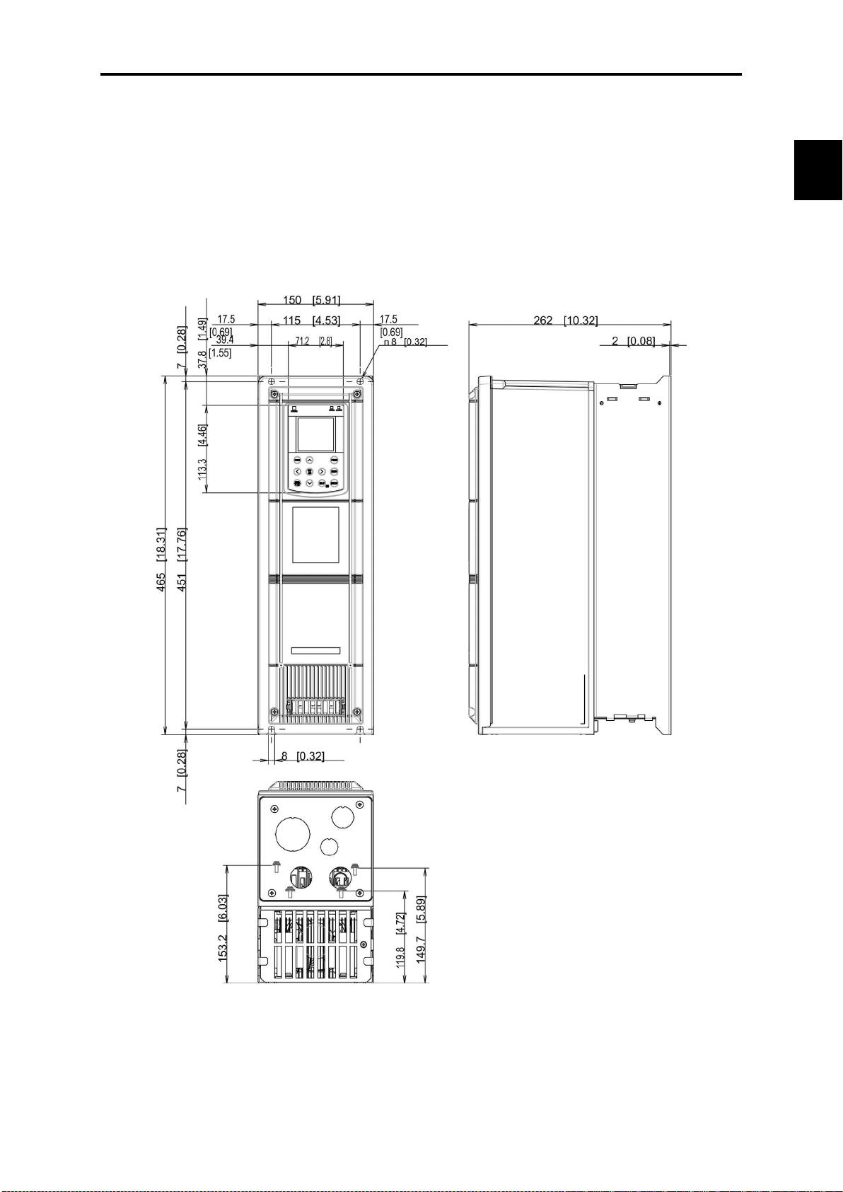
Chap. 2
SPECIFICATIONS
2.9 External Dimensions
2.9.1 Standard models
FRN001AR1-2U to FRN005AR1-2U,
FRN001AR1-4U to FRN010AR1-4U,
FRN001AR1-5U to FRN010AR1-5U
2.9 External Dimensions
Figure 1 External Dimensions of the Inverter
2-51
Page 85

FRN007AR1-2U to FRN015AR1-2U,
FRN015AR1-4U to FRN030AR1-4U,
FRN015AR1-5U to FRN030AR1-5U
Figure 2 External Dimensions of the Inverter
2-52
Page 86

Chap. 2
SPECIFICATIONS
FRN020AR1-2U, FRN025AR1-2U,
FRN040AR1-4U, FRN050AR1-4U,
FRN040AR1-5U, FRN050AR1-5U
2.9 External Dimensions
Figure 3 External Dimensions of the Inverter
2-53
Page 87

FRN030AR1-2U, FRN040AR1-2U,
FRN060AR1-4U, FRN075AR1-4U
FRN060AR1-5U, FRN075AR1-5U
Figure 4 External Dimensions of the Inverter
2-54
Page 88

Chap. 2
SPECIFICATIONS
FRN050AR1-2U, FRN060AR1-2U,
FRN100AR1-4U, FRN125AR1-4U
FRN100AR1-5U, FRN150AR1-5U
2.9 External Dimensions
Figure 5 External Dimensions of the Inverter
2-55
Page 89
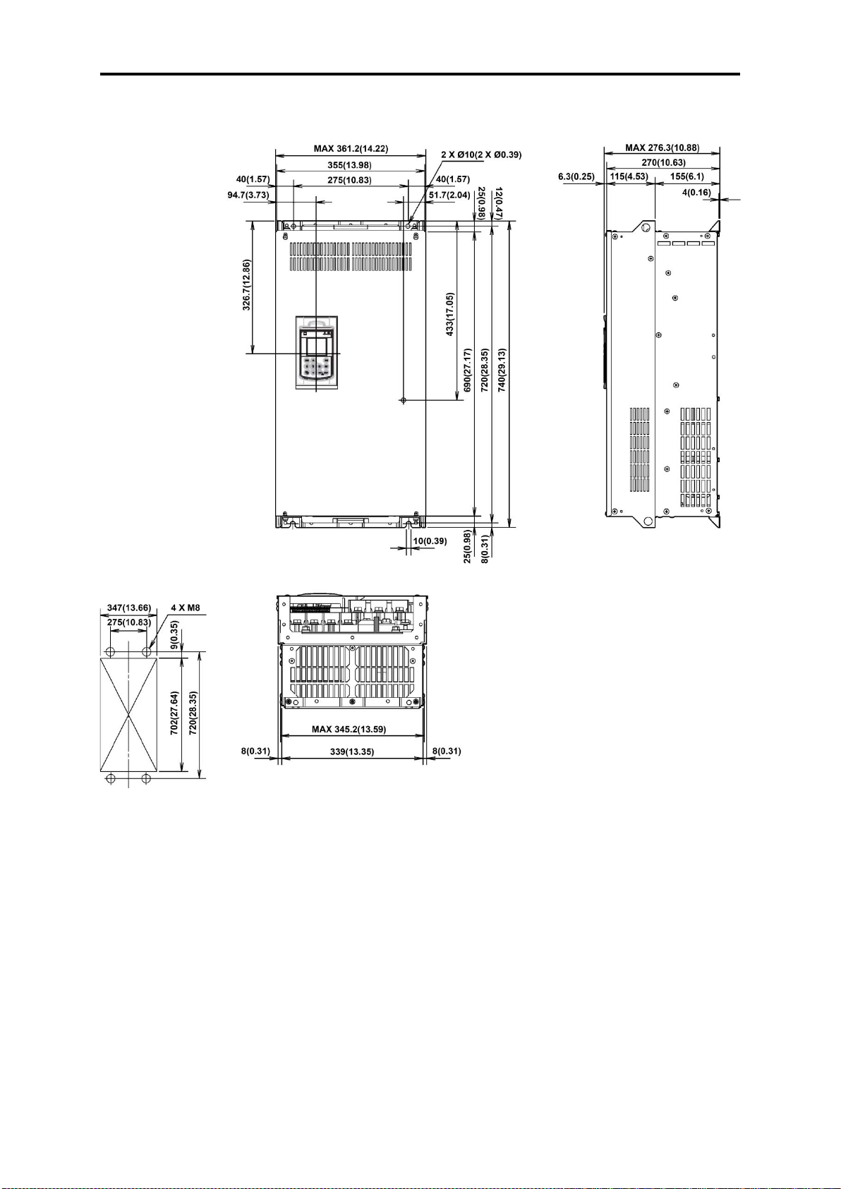
Panel cutout
FRN075AR1S-2U, FRN100AR1S-2U
Figure 6 External Dimensions of the Inverter
2-56
Page 90

Chap. 2
SPECIFICATIONS
FRN125AR1S-2U
2.9 External Dimensions
Panel cutout
Figure 7 External Dimensions of the Inverter
2-57
Page 91

Panel cutout
FRN150AR1S-4U, FRN200AR1S-4U,
Figure 8 External Dimensions of the Inverter
2-58
Page 92
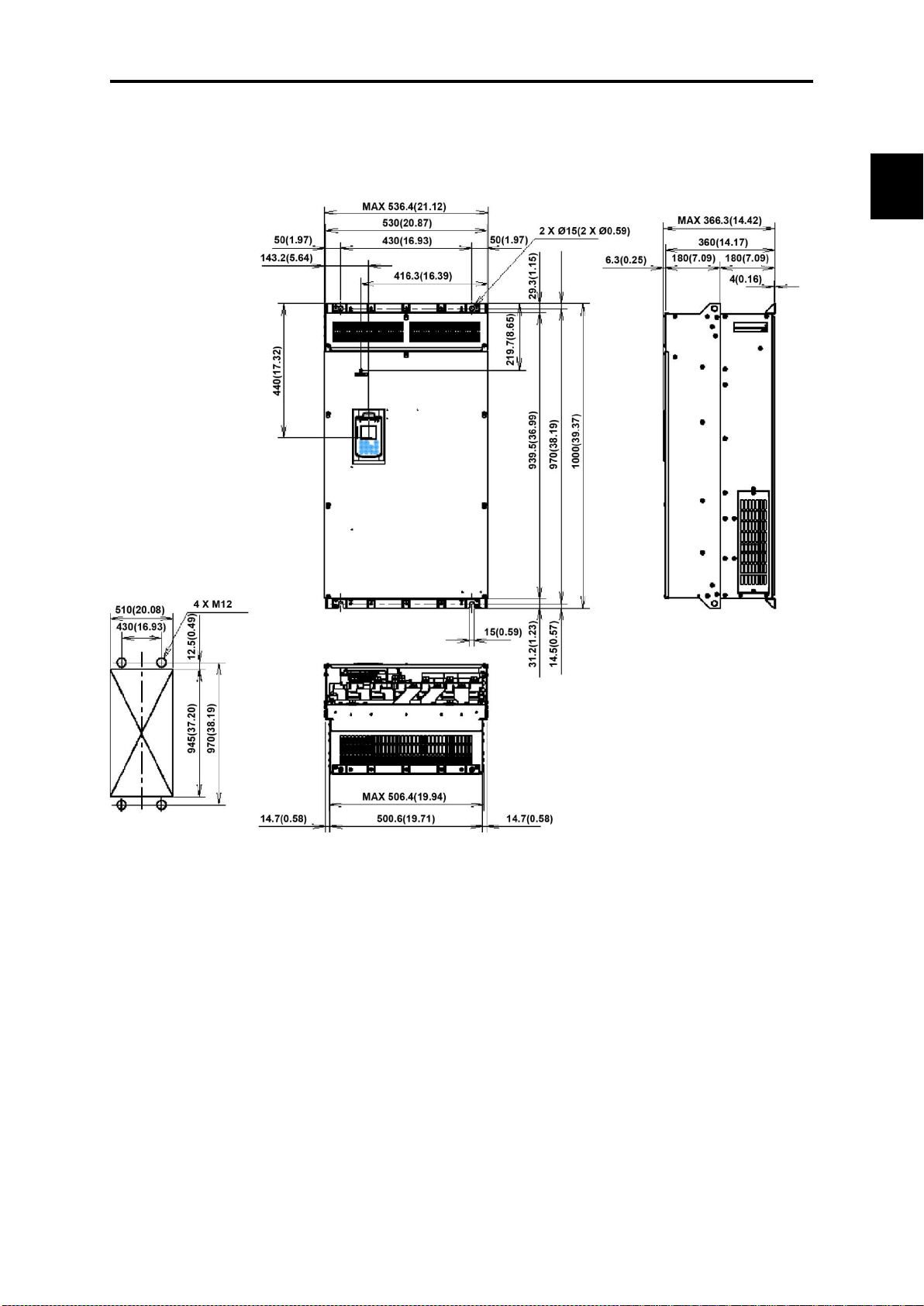
Chap. 2
SPECIFICATIONS
Panel cutout
FRN250AR1S-4U, FRN300AR1S-4U,
FRN200AR1S-5U, FRN300AR1S-5U
2.9 External Dimensions
Figure 9 External Dimensions of the Inverter
2-59
Page 93

FRN350AR1S-4U, FRN450AR1S-4U
Panel cutout
Figure 10 External Dimensions of the Inverter
2-60
Page 94

Chap. 2
SPECIFICATIONS
Panel cutout
FRN500AR1S-4U, FRN600AR1S-4U
2.9 External Dimensions
Figure 11 External Dimensions of the Inverter
2-61
Page 95
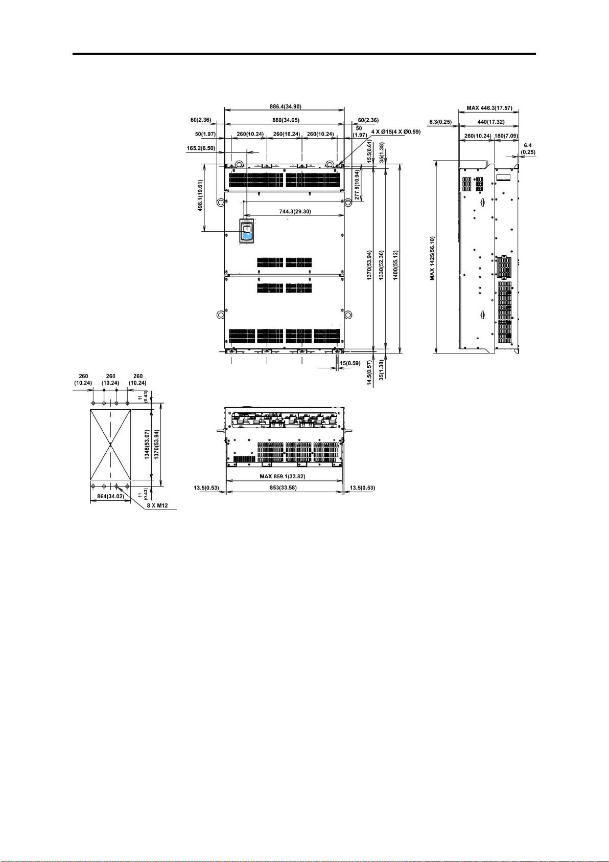
Panel cutout
FRN800AR1S-4U
Figure 12 External Dimensions of the Inverter
2-62
Page 96
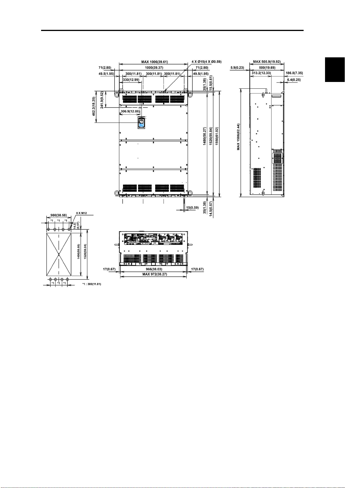
Chap. 2
SPECIFICATIONS
Panel cutout
FRN900AR1S-4U, FRN1000AR1S-4U
2.9 External Dimensions
Figure 13 External Dimensions of the Inverter
2-63
Page 97

2.9.2 Keypad
2-64
Page 98

Chap. 2
SPECIFICATIONS
Power supply
50/60 Hz
2.10 Connection Diagrams
2.9 External Dimensions
[ 1 ] FRN060AR1-2U / FRN125AR1
SINK mode input with Enable input function used (factory default)
230V class series
200 to 240 V
50/60 Hz
400V class series
380 to 480 V
50/60 Hz
575V class series
575 to 600 V
U / FRN150AR1
-4
U or below and
-5
2-65
Page 99

Power supply
50/60 Hz
SOURCE mode input with Enable input function used
230V class series
200 to 240 V
50/60 Hz
400V class series
380 to 480 V
50/60 Hz
575V class series
575 to 600 V
2-66
Page 100

Chap. 2
SPECIFICATIONS
Power supply
50/60 Hz
2.9 External Dimensions
[ 2 ] FRN075AR1S-2U or above and FRN150AR1S-4U or above and FRN200AR1S-5U
or above
SINK mode input with Enable input function used (factory default)
230V class series
200 to 240 V
50/60 Hz
400V class series
380 to 480 V
50/60 Hz
575V class series
575 to 600 V
2-67
 Loading...