

Page 1

Buy: www.ValinOnline.com | Phone 844-385-3099 | Email: CustomerService@valin.com
Non-Bypass Panels
FRENIC-EcoPAK
Instruction Manual
Fuji Electric Corp. of America FECA-IN-106 / 122010
Information subject to change without notice.
Page 2

Safety Precautions
Buy: www.ValinOnline.com | Phone 844-385-3099 | Email: CustomerService@valin.com
Read this manual thoroughly before proceeding with installation, connections (wiring), or
maintenance and inspection. Ensure you have sound knowledge of the device and
familiarize yourself with all safety information and precautions before proceeding to
operate the drive. Refer to the
for further safety information.
Safety precautions are classified into the following two categories in this manual.
WARNING
Failure to heed the information indicated by this symbol may lead to dangerous
conditions, possibly resulting in death or serious bodily injuries.
CAUTION
Failure to heed the information indicated by this symbol may lead to dangerous
conditions, possibly resulting in minor or light bodily injuries and/or substantial property
damage.
FRENIC-Eco drive instruction manual (INR-SI47-1225-E)
Page 2 of 22
Page 3

FRENIC-EcoPAK Non-Bypass Panel Overview
Buy: www.ValinOnline.com | Phone 844-385-3099 | Email: CustomerService@valin.com
The FRENIC-EcoPAK non-bypass panel is a packaged drive solution in a Type 1
enclosure. NEMA 12 ventilated enclosure is available as an option.
Features
Type 1 enclosure with “space-saving” footprint
Metallic enclosures to reduce radio frequency
interference (RFI)
Integral main disconnect with branch circuit
protection, including a padlockable through-the-door
operator handle mechanically interlocked with the
enclosure door
DC link reactor provided as standard to minimize
harmonics, with the option of a 3% or 5% AC line
reactor to minimize harmonics and provide transient
voltage protection for the drive
Control power transformer with primary & secondary
fusing
Door mounted drive keypad with backlit LCD and LED
displays for drive set-up, troubleshooting, local operation
control, maintenance indication, and operational indication
Damper Control Output Contacts
Built-in communications, user selectable between
Modbus RTU, Metasys
with additional communication options including:
ONWORKS
L
UL/cUL Listed
®
, BACnet, DeviceNet, and Profibus DP
APOGEE is a registered trademark of Siemens Building Technologies, Inc.
ONWORKS is a registered trademark of Echelon Corporation.
L
Metasys is a registered trademark of Johnson Controls, Inc
®
N2, or APOGEE® FLN (P1),
Page 3 of 22
Page 4
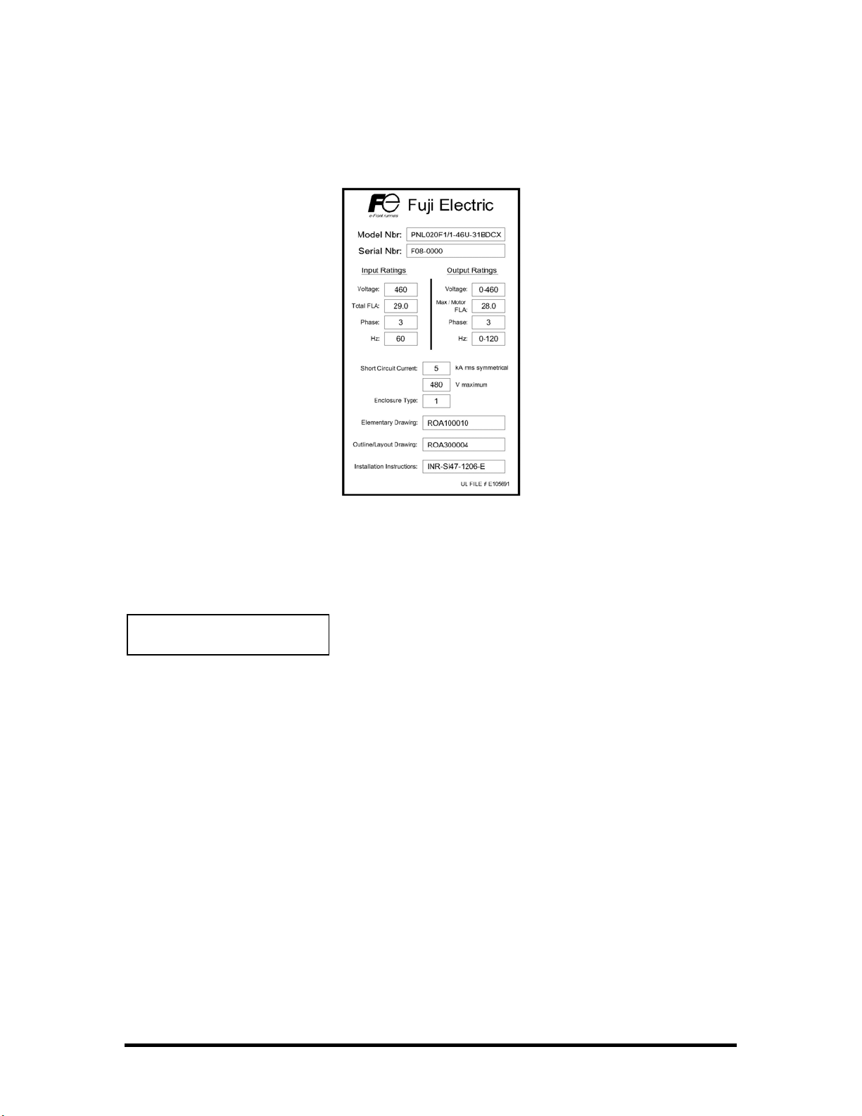
Panel Identification
Buy: www.ValinOnline.com | Phone 844-385-3099 | Email: CustomerService@valin.com
Each FRENIC-EcoPAK panel has a nameplate label, like the example pictured above,
which contains important information about the panel. This label is located on the inside
of the hinged door on the enclosure.
CAUTION
Refer to the nameplate label to determine the panel input voltage and current
requirements prior to installation and wiring.
Refer to the nameplate label for the correct wiring diagram (Elementary Drawing).
Sizing of field wiring conductors should be based upon the current ratings listed on
the nameplate label.
Page 4 of 22
Page 5

Installation
Buy: www.ValinOnline.com | Phone 844-385-3099 | Email: CustomerService@valin.com
CAUTION
The FRENIC-EcoPAK panel should be located indoors:
Away from flammable or combustible liquids, gases, and other materials
Away from sources of dust, metal shavings, or other particulate material
Away from liquids, spray, or mist
Away from sources of heat
Away from direct sunlight
Where the ambient temperature will remain between -10°C (14°F) and 40°C
(104°F)
Wall-mount panels must be mounted on a non-flammable heat-resistant surface that is
capable of supporting the weight of the panel.
Refer to the dimensional drawing that shipped with the panel for required clearances.
Routing of field wiring should be planned in coordination with choosing a mounting
location.
Page 5 of 22
Page 6

Wiring Overview
Buy: www.ValinOnline.com | Phone 844-385-3099 | Email: CustomerService@valin.com
The FRENIC-EcoPAK panel must be connected to an input power source, a motor
(output power), and control signals.
WARNING
Wiring should be performed by a qualified electrician using standard practices as
specified by local and national codes.
Always make sure the input power source is OFF before connecting or disconnecting
any power input, output, or control wiring.
Ground the panel, as specified by local and national codes, using the provided
grounding lugs or bus bar.
Make sure that the input power source (phases, voltage, and current capacity)
matches the requirements of the panel as stated on the nameplate.
Never connect line voltage to the drive output terminals (U, V, and W).
When making holes for conduit fittings, be sure to cover the drive and other
components to protect them from metal shavings.
CAUTION
All field wiring should be copper with a minimum insulation rating of 75°C.
Sizing of field wiring conductors should be based upon the current ratings listed on
the nameplate label, in accordance with local and national codes.
Refer to the wiring diagram that shipped with this panel and the torque table in this
instruction manual.
Refer to the diagrams on the following pages for general component layout and for
general routing of power input, power output (motor connections), and control wiring for
your panel. Power input wiring should be routed away from power output wiring, and
both should enter the panel from separate conduit. Control wiring should be routed away
from power wiring, and should enter the panel from separate conduit. Knockouts are
provided on the Type 1 wall-mount panels. Floor-mount and NEMA 12 ventilated wallmount panels require holes to be drilled in the field. Refer to the panel outline drawing
provided for recommended conduit locations.
Refer to the following section Control Wiring for descriptions of the control connections.
Page 6 of 22
Page 7

Wiring Overview (cont’d)
Buy: www.ValinOnline.com | Phone 844-385-3099 | Email: CustomerService@valin.com
UL/NEMA Type 1 UL/NEMA Type 1
2-10Hp @ 208/230V 15-20Hp @ 208/230V
2-20Hp @ 460V 25-40Hp @ 460V
Page 7 of 22
Page 8

Wiring Overview (cont’d)
Buy: www.ValinOnline.com | Phone 844-385-3099 | Email: CustomerService@valin.com
NEMA 12 Ventilated NEMA 12 Ventilated
2-30Hp @ 208/230V 40Hp @ 208/230V
2-40Hp @ 460V 50-75Hp @ 460V
Page 8 of 22
Page 9

Wiring Overview (cont’d)
Buy: www.ValinOnline.com | Phone 844-385-3099 | Email: CustomerService@valin.com
UL/NEMA Type 1 UL/NEMA Type 1
25-30Hp @ 208/230V 40-60Hp @ 208/230V
50-75Hp @ 460V 100-200Hp @ 460V
NEMA 12 Ventilated
50-60Hp @ 208/230V
100-200Hp @ 460V
Page 9 of 22
Page 10

Control Wiring
Buy: www.ValinOnline.com | Phone 844-385-3099 | Email: CustomerService@valin.com
All control wiring, except the damper control output and the programmable relay outputs,
connects to the terminals on the drive. The following diagram shows control connections
that are available on
FRENIC-EcoPAK panels:
Description of Control Connections
Damper Control output (DMPRLY):
o CTB 1-2
o Used to control the position of a damper valve in coordination with drive
operation
Programmable Relay 1 output (PRLY1):
o CTB 3-4 for NO contacts rated for 1A @ 230VAC
o Provides drive output signal Y2, which is user-selectable
Programmable Relay 2 output (PRLY2):
o CTB 5-6 for NO contacts rated for 1A @ 230VAC
o Provides drive output signal Y3, which is user-selectable
Page 10 of 22
Page 11

Field Wiring Torque and Wire Size Values for FRENIC-EcoPAK 208/230V
Buy: www.ValinOnline.com | Phone 844-385-3099 | Email: CustomerService@valin.com
HP Circuit Breaker Fusible Disconnect Terminal Blocks
'CB' 'FUSDISC' 'CTB'
2 n/a 17 in.lb. 4.5 in.lb.
18-8 AWG 22-12 AWG
3 n/a 17 in.lb. 4.5 in.lb.
18-8 AWG 22-12 AWG
5 n/a 17 in.lb. 4.5 in.lb.
18-8 AWG 22-12 AWG
7.5 62 in.lb. 17 in.lb. 4.5 in.lb.
14-1 AWG 18-8 AWG 22-12 AWG
10 62 in.lb. 30 in.lb. 4.5 in.lb.
14-1 AWG 14-4 AWG 22-12 AWG
15 62 in.lb. 30 in.lb. 4.5 in.lb.
14-1 AWG 14-4 AWG 22-12 AWG
20 62 in.lb. 120 in.lb. 4.5 in.lb.
14-1 AWG 14-2/0 AWG 22-12 AWG
25 88 in.lb. 120 in.lb. 4.5 in.lb.
14 AWG to 300kcm 14-2/0 AWG 22-12 AWG
30 88 in.lb. 275 in.lb. 4.5 in.lb.
14 AWG to 300kcm 4 AWG to 300kcm 22-12 AWG
40 88 in.lb. 275 in.lb. 4.5 in.lb.
14 AWG to 300kcm 4 AWG to 300kcm 22-12 AWG
50 88 in.lb. 275 in.lb. 4.5 in.lb.
14 AWG to 300kcm 4 AWG to 300kcm 22-12 AWG
60 221 in.lb. 500 in.lb. 4.5 in.lb.
6 AWG to 500kcm 2 AWG to 600kcm 22-12 AWG
Note: Wire ranges provided indicate conductor sizes that the device terminal or lug will
accept. Follow local and national codes for proper conductor sizing.
Page 11 of 22
Page 12

Field Wiring Torque and Wire Size Values for FRENIC-EcoPAK 460V
Buy: www.ValinOnline.com | Phone 844-385-3099 | Email: CustomerService@valin.com
HP Circuit Breaker Fusible Disconnect Terminal Blocks
'CB' 'FUSDISC' 'CTB'
2 n/a 17 in.lb. 4.5 in.lb.
18-8 AWG 22-12 AWG
3 n/a 17 in.lb. 4.5 in.lb.
18-8 AWG 22-12 AWG
5 n/a 17 in.lb. 4.5 in.lb.
18-8 AWG 22-12 AWG
7.5 n/a 17 in.lb. 4.5 in.lb.
18-8 AWG 22-12 AWG
10 n/a 17 in.lb. 4.5 in.lb.
18-8 AWG 22-12 AWG
15 62 in.lb. 17 in.lb. 4.5 in.lb.
14-1 AWG 18-8 AWG 22-12 AWG
20 62 in.lb. 30 in.lb. 4.5 in.lb.
14-1 AWG 14-4 AWG 22-12 AWG
25 62 in.lb. 30 in.lb. 4.5 in.lb.
14-1 AWG 14-4 AWG 22-12 AWG
30 62 in.lb. 30 in.lb. 4.5 in.lb.
14-1 AWG 14-4 AWG 22-12 AWG
40 62 in.lb. 120 in.lb. 4.5 in.lb.
14-1 AWG 14-2/0 AWG 22-12 AWG
50 62 in.lb. 120 in.lb. 4.5 in.lb.
14-1 AWG 14-2/0 AWG 22-12 AWG
60 62 in.lb. 120 in.lb. 4.5 in.lb.
14-1 AWG 14-2/0 AWG 22-12 AWG
75 88 in.lb. 275 in.lb. 4.5 in.lb.
14 AWG to 300kcm 4 AWG to 300kcm 22-12 AWG
100 88 in.lb. 275 in.lb. 4.5 in.lb.
14 AWG to 300kcm 4 AWG to 300kcm 22-12 AWG
125 88 in.lb. 275 in.lb. 4.5 in.lb.
14 AWG to 300kcm 4 AWG to 300kcm 22-12 AWG
150 88 in.lb. 500 in.lb. 4.5 in.lb.
14 AWG to 300kcm 2 AWG to 600kcm 22-12 AWG
200 221 in.lb. 500 in.lb. 4.5 in.lb.
6 AWG to 500kcm 2 AWG to 600kcm 22-12 AWG
Note: Wire ranges provided indicate conductor sizes that the device terminal or lug will
accept. Follow local and national codes for proper conductor sizing.
Page 12 of 22
Page 13

BASIC PANEL STARTUP
Buy: www.ValinOnline.com | Phone 844-385-3099 | Email: CustomerService@valin.com
CAUTION
Make sure all power and control wiring is completed before proceeding.
As with all electrical equipment installations, insure all safety/wiring instructions have
been followed in accordance with this product’s manuals and local and national
codes.
1. Energize panel by turning disconnect switch to the ‘ON’ position.
2. Set drive parameters for the connected motor (refer to table below). Set drive speed
control to ‘Local’ by pushing the ‘REM/LOC’ button on the drive keypad.
3. Push the ‘FWD’ button on the keypad to energize the drive. Use the Up/Down keys
to change the drive speed as necessary.
4. Check that the motor rotates in the correct direction. To change, refer to the
Troubleshooting section in this manual.
5. Measure and record motor FLA if required. Allow motor to run at full speed for a
sufficient time to insure panel-mounted overloads are properly set. Adjust, if
necessary.
6. Push the ‘Stop’ button on the keypad and allow the motor to come to a complete
stop.
7. De-energize panel.
8. Record startup data and change any parameters as necessary.
Page 13 of 22
Page 14

Setting Up Local Control
Buy: www.ValinOnline.com | Phone 844-385-3099 | Email: CustomerService@valin.com
Also refer to the following section Programming the FRENIC-Eco Drive and the FRENIC-
drive instruction manual (INR-SI47-1225-E) for more information.
Eco
The FRENIC-EcoPAK panel was intended to be integrated into a building automation
system and controlled by remote signals. If these signals are not available, the panel can
be set up to be operated locally. Follow these steps to set the panel up for local
operation:
1. Set drive function code F01 to 0.
2. Set drive function code F02 to 2.
3. Set drive function code H96 to 3.
The panel can now be operated directly using the drive keypad.
Page 14 of 22
Page 15

COMMON PARAMETER SETTINGS
Buy: www.ValinOnline.com | Phone 844-385-3099 | Email: CustomerService@valin.com
Also refer to the FRENIC-Eco drive instruction manual (INR-SI47-1225-E) for more
information.
Factory-set drive parameters and settings
These parameters and settings are pre-set from the factory for the panel to be
operational. If, for some reason, the drive parameters are reinitialized, these parameters
must be reset for correct panel operation.
Drive function codes:
F01 = 3
F02 = 1
F05 = 230 (for 230V panels only - default otherwise)
F11 = nameplate output current
F16 = 3
E01 = 1007
E02 = 1007
E03 = 1009
E20 = 55
E21 = 0
E22 = 0
E24 = 0
H09 = 4
H96 = 0
Drive Switches:
SW1 set to SINK
SW5 set to V2
Page 15 of 22
Page 16

Programming the FRENIC-Eco Drive
Buy: www.ValinOnline.com | Phone 844-385-3099 | Email: CustomerService@valin.com
Also refer to Chapter 3 in the FRENIC-Eco drive instruction manual (INR-SI47-1225-E)
for more information.
Page 16 of 22
Page 17

Programming the FRENIC-Eco Drive (cont’d)
Buy: www.ValinOnline.com | Phone 844-385-3099 | Email: CustomerService@valin.com
To set drive parameters using the keypad, first make sure the drive is stopped.
Parameters cannot be changed while the drive is running. To enter the programming
menu, press the Program Key (PRG) on the keypad. To return to the previous screen,
press either (PRG) or (RESET). To select a menu item, use the (UP) and (DOWN) keys
on the keypad, then press the (FUNC/DATA) key to go to that screen. Refer to the
diagram below for an example of navigating the menu:
Function code settings can be changed using the (UP) and (DOWN) keys on the
keypad. Pressing (FUNC/DATA) saves the changes, while pressing (RESET) discards
the changes, and both return to the previous menu.
The most frequently modified parameters can be accessed in the ‘Quick-Set’ menu (item
0 on the programming menu screen). All parameters can be accessed in the ‘Data-Set’
menu (item 1 on the programming menu screen).
Recommended user-set drive parameters
These parameters are all in the FRENIC-Eco drive Quick-Start menu for easy access.
F07 Acceleration Time.
F08 Deceleration Time.
F10/F11 Electronic Overload.
F14 Restart Settings. Refer to drive instruction manual.
F26 Motor Sound (carrier frequency).
P02 Motor Capacity (HP).
P03 Motor FLA.
P04 Motor Tuning. Refer to drive instruction manual.
Page 17 of 22
Page 18

OPERATION
Buy: www.ValinOnline.com | Phone 844-385-3099 | Email: CustomerService@valin.com
Operator Controls
FRENIC-EcoPAK panel includes the following controls for local operation and
The
monitoring:
Main power disconnect
Drive keypad
The FRENIC-EcoPAK panel includes the following controls for remote operation and
monitoring:
Analog speed reference input
Analog monitor output
Run input
Enable input
Drive Fault output
Drive Run output
Damper control output
Page 18 of 22
Page 19

MAINTENANCE
Buy: www.ValinOnline.com | Phone 844-385-3099 | Email: CustomerService@valin.com
Periodic Maintenance
The following items require periodic inspection and maintenance:
Fans should be checked for proper operation and filters checked and/or
replaced on a schedule that suits local conditions.
Power wiring connections should be checked and re-torqued every six
months.
Refer to the
maintenance requirements and schedule.
Fans and Filters
For replacement fans (out of warranty period) and filter media, refer to the following
tables:
Size Manufacturer Part Number Manufacturer Part Number
A Qualtek Fan-S 09450-M/30 Orion OP109AP-11-1TB
B Qualtek Fan-S 09650-M/30 Orion OA172AP-11-1TB
208/230V
Fan
HP
2 A 1 A 2 A 1 A 2
3 A 1 A 2 A 1 A 2
5 A 1 A 2 A 1 A 2
7.5 A 1 A 2 B 1 B 2
10 A 1 A 2 B 1 B 2
15 A 1 A 2 B 1 B 2
20 A 1 A 2 B 1 B 2
25 A 1 A 2 B 1 B 2
30 A 2 A 4 B 1 B 2
40 A 3 A 7 B 2 B 4
50 A 3 A 7 B 3 B 7
60 B 4 A, B 8, 4 B 4 A, B 8, 4
Size
FRENIC-Eco drive instruction manual (INR-SI47-1225-E) for drive
Filter Fan
NEMA 1 NEMA 12
QTY
Filter
Size(s)
QTY
Fan
Size
QTY
Filter
Size(s)
QTY
Page 19 of 22
Page 20

Maintenance (cont’d)
Buy: www.ValinOnline.com | Phone 844-385-3099 | Email: CustomerService@valin.com
460V
Fan
HP
2 A 1 A 2 A 1 A 2
3 A 1 A 2 A 1 A 2
5 A 1 A 2 A 1 A 2
7.5 A 1 A 2 A 1 A 2
10 A 1 A 2 B 1 B 2
15 A 1 A 2 B 1 B 2
20 A 1 A 2 B 1 B 2
25 A 1 A 2 B 1 B 2
30 A 1 A 2 B 1 B 2
40 A 1 A 2 B 1 B 2
50 A 2 A 4 B 2 B 4
60 A 2 A 4 B 2 B 4
75 A 2 A 4 B 2 B 4
100 A 3 A 7 B 3 B 7
125 A 3 A 7 B 3 B 7
150 B 4 A, B 8, 4 B 4 A, B 8, 4
200 B 4 A, B 8, 4 B 4 A, B 8, 4
Size QTY
NEMA 1 NEMA 12
Filter
Size(s) QTY
Fan
Size QTY
Filter
Size(s) QTY
Page 20 of 22
Page 21

Maintenance (cont’d)
Buy: www.ValinOnline.com | Phone 844-385-3099 | Email: CustomerService@valin.com
Fuses
The FRENIC-EcoPAK panel has labels, located on the inside of the hinged door, which
list the correct size and type of fuses to be used for that panel. In the event that these
labels are damaged or missing, please refer to the tables below for replacement fuse
type and sizing:
208/230V
HP Class J Class CC Glass
210 1 8/10
315 1 8/10
525 1 8/10
7.5 30 1 8/10
10 45 1 8/10
15 60 1 8/10
20 80 1 8/10
25 100 1 1 6/10
30 125 1 8/10 1 6/10
40 175 3 1/2 3 2/10
50 200 3 1/2 3 2/10
60 250 9 8
MAIN CPT CPT
POWER PRIMARY SECONDARY
460V MAIN CPT CPT
POWER PRIMARY SECONDARY
HP Class J Class CC Glass
2 6 4/10 8/10
3 8 4/10 8/10
5 12 4/10 8/10
7.5 15 4/10 8/10
10 25 4/10 8/10
15 30 4/10 8/10
20 40 4/10 8/10
25 50 4/10 8/10
30 60 4/10 8/10
40 70 4/10 8/10
50 90 8/10 1 6/10
60 100 8/10 1 6/10
75 150 8/10 1 6/10
100 175 1 6/10 3 2/10
125 200 1 6/10 3 2/10
150 250 4 8
200 350 4 8
Fuse Reference - Ferraz Shawmut series (type)
Main Power: AJT (Time-delay Class J)
CPT Primary: ATQR (Time-delay Class CC)
CPT Secondary: GGC (Fast Acting Glass)
Page 21 of 22
Page 22

TROUBLESHOOTING
Buy: www.ValinOnline.com | Phone 844-385-3099 | Email: CustomerService@valin.com
Drive
For drive-specific issues, refer to the FRENIC-Eco drive instruction manual (INR-SI471225-E).
Motor Rotation
Problem: Motor turns incorrect direction.
Solution: Swap two of the three motor output connections.
Page 22 of 22
 Loading...