

Page 1

Variable Torque Load Inverters for Fans and Pumps
MEH532a
Page 2
Variable Torque AC Drives for Fans and Pumps!
Enhanced Energy Savings
!
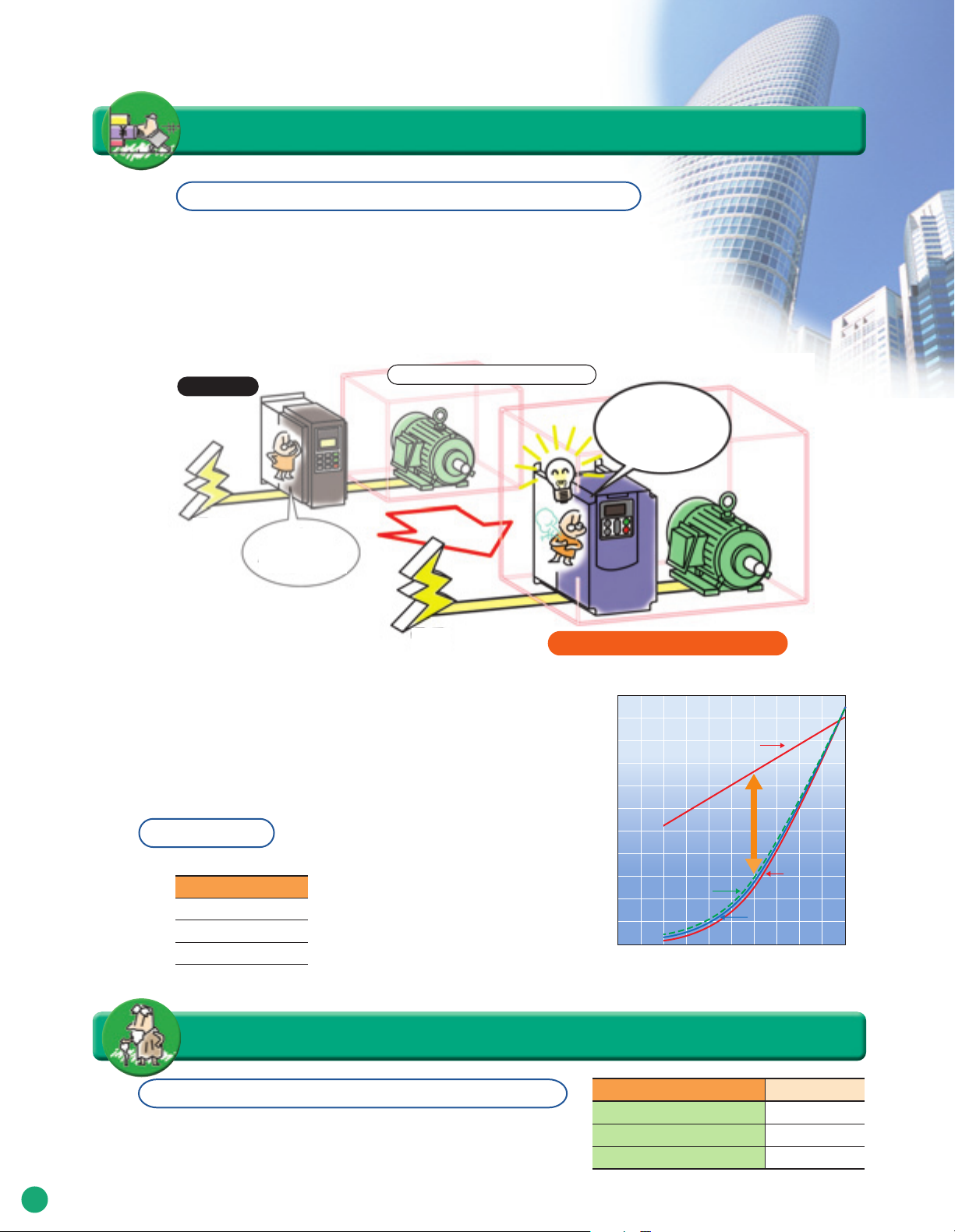
Optimizing Energy-Savings for the complete system
In addition to optimizing the control of the applied motor for Energy-Savings, FRENICEco series drives also optimizes power consumption of the drive for maximizing EnergySavings for the complete system. With regulations expected to call for a reduction of
1% or more in annual energy consumption, Fuji Electric is aiming to optimize energysavings as a complete system approach and not focusing only on reducing energy
consumed by the motor.
Previous
Power
supply
Optimum
motor control
Way of thinking about the power used
Optimum control
of overall system
Power
supply
Using this new system, energy savings is several percent improved over that of the
previous models.
Kyoto Agreement, which was studied at the Conference on Prevention of Global Warming
(COP3), was ratified by Russia in October 2004, and thereby put into effect on February 16,
2005. In the future, the related regulations are calling for a reduction in energy consumption
of 1% or more each succeeding year, and therefore, we are aiming to build energy saving
features into equipment as a whole.
FRENIC-Eco is the inverter equipped with
the industry's highest level of efficiency (low power loss).
Power Monitor
Power-related data can be checked via the inverter unit's keypad.
Items
Power (kW)
Cumulative power (kWh)
Cumulative power rates ($/kWh)
* Cumulative values can be reset. Cumulative power rates are shown with the power rate set at
so much per kWh (display coefficient). Rates in other currency can also be displayed.
New control system (FRENIC-Eco)
■
Energy saving effect compared with Fuji's previous models
110
100
90
Characteristic curve achieved
by controlling a damper or valve
80
70
60
50
40
Power consumption P (%)
30
Inverter control
20
(V/f control)
10
0
10 20 30 40 50 60 70 80 90 100
(The effect varies dependent on the motor's characteristics.)
Energy savings
Air volume or flow rate Q (%)
Long life design that meets your expectation
effect
(Optimal minimum
Previous auto energy
saving control
New auto energy
saving control
power control)
!
Built with longer lasting replaceable components to give a longer service life!
The design life of replaceable components in each inverter model has
been extended to
capacitors is measured and temperature compensation carried out to
2
match the cumulative operating time of the electrolytic capacitors on the
printed circuit board.
10 years
. In addition, the capacity of the main circuit
Life-limited component name Designed life
Main circuit capacitors
Electrolytic capacitors on printed circuit board
Cooling fan
Note: 7 years for 50HP or larger models
[Conditions] Ambient temperature: 40˚C (104˚F), Load factor: 80% of inverter's rated current
•
The life may be shorter depending on surrounding conditions.
(Note)
10 years
10 years
10 years
Page 3
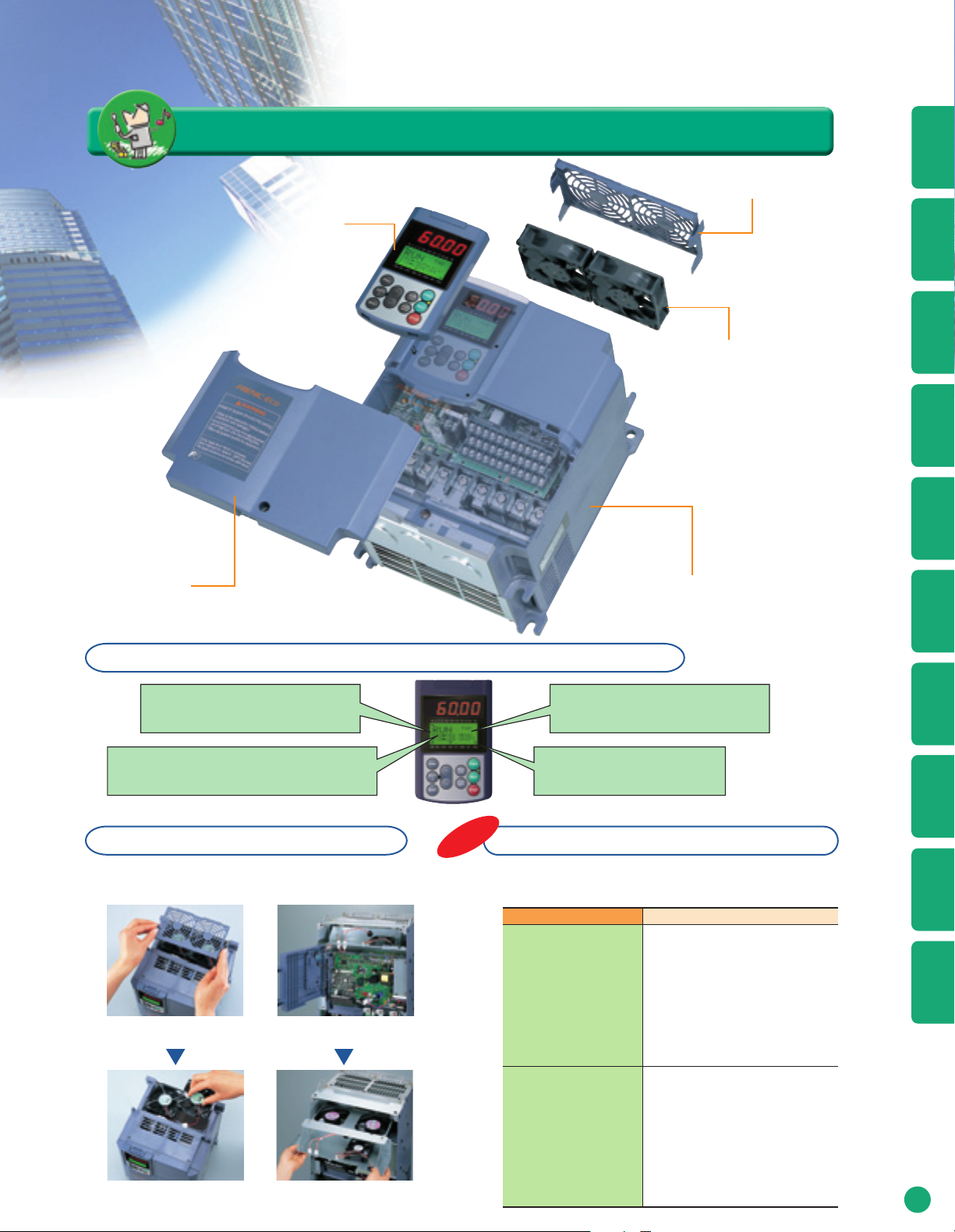
Saves energy and cuts costs.
Inverter cover
Maintenance is simplified for both the drive and equipment
Cooling fan cover
Keypad
Cooling fan
Inverter body
!
Specifications
Functions
Protective
External
Dimensions
Wiring
Diagram
Terminal
Functions
The service life information for replaceable inverter components is displayed.
Main circuit capacitor capacity
Printed circuit board electrolytic
capacitor cumulative operating time
(with temperature compensation)
Simple replacement of replaceable components
Cooling fan replacement procedure
●20HP model ●60HP model
Cooling cover can be removed with
one touch.
The inverter's mounting screws and power
connector can be removed from the front.
Industry first
Information is displayed with equipment maintenance in mind.
In addition to maintenance information for the inverter unit,
information related to equipment maintenance is also displayed.
Cooling fan cumulative operating time
(with cooling fan ON/OFF control compensation)
Inverter operating time
Item
The cumulative operating time
of the equipment the inverter is
Motor cumulative
operating time
(hours)
used with is calculated.
Example of Use
If the inverter is used for fan
control, this time can be used as
a criterion for replacing the belts
used on pulleys.
Purpose
Keypad
Operations
Settings
Function
Peripheral Equipment
Connection Diagrams
OptionsWarranty
Disconnect the power connector and
change the cooling fan cartridge.
The cooling fan cartridge can be replaced
by sliding the holder out to the front
Number of starts
(times)
The number of times the inverter is
run and stopped can be counted.
Example of Use
The number of times the equipment is started and
stopped is recorded, so this can be used as a
criterion for replacing parts in equipment where
starting and stopping is a burden on the machine.
3
Page 4
Equipped with the optimum functions for HVAC (Air conditioning systems)
!
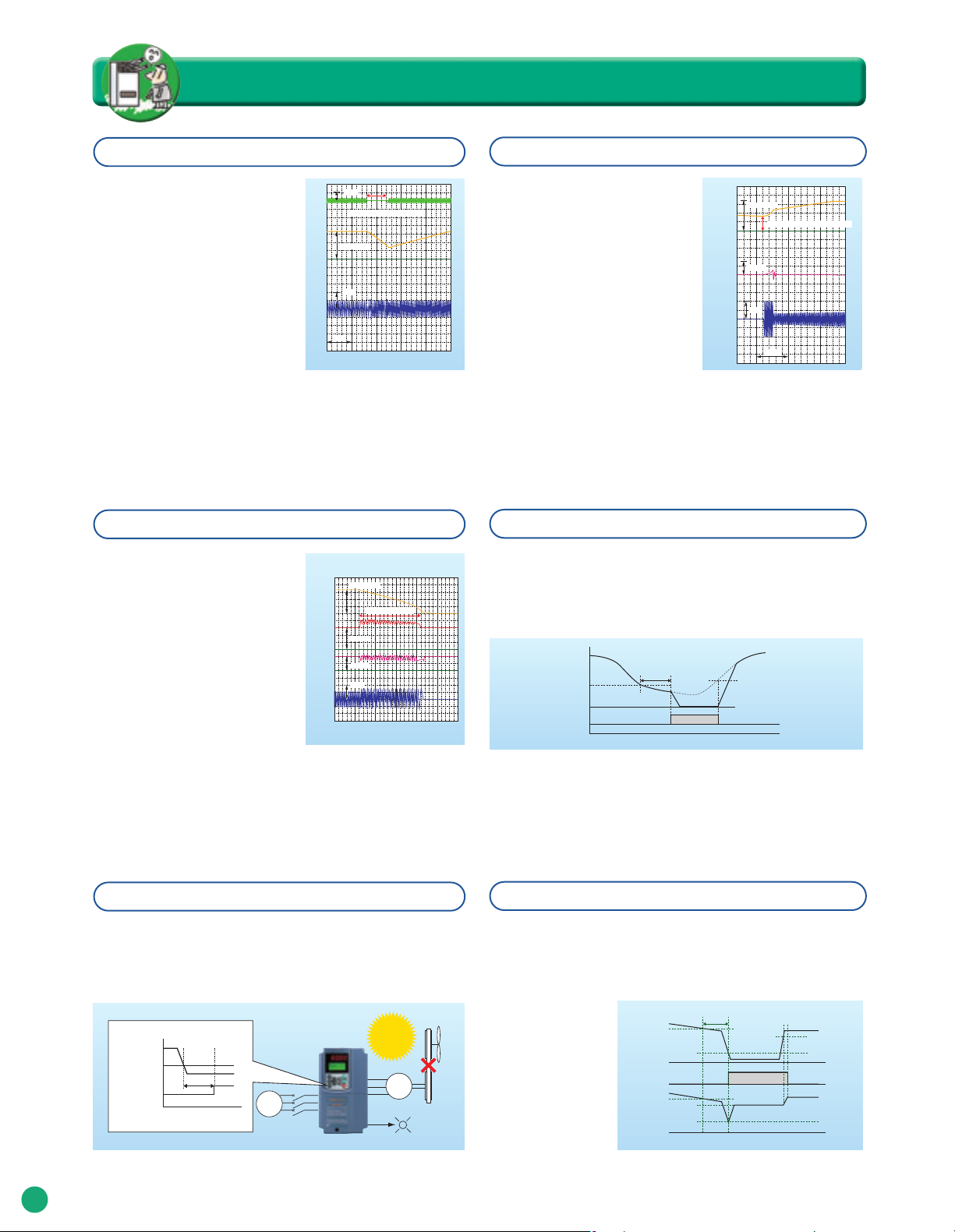
Operation is continued even after the momentary power failure thanks to the auto-restart function.
Even if a momentary power failure
occurs, load inertia of a fan or
blower, etc. is used to maintain
the motor's operation while the
motor's operating speed gradually
drops, and enables the motor to
restart operation without stopping.
(The motor may stop on occasion
due to the load's inertia.)
2kV
Power
supply
voltage
Momentary power failure time: 825 ms
1500r/min
Motor
speed
20A
Output
current
1s
Inverter : FRN007F1S-2U
Motor : 7.5HP
Tripless operation through regenerated current avoidance control
Deceleration time is controlled to match
the internal energy level generated in
the inverter, and so deceleration and
stopping is accomplished without
tripping due to overload.
Motor
speed
DC link
circuit
voltage
Torque
Output
current
1500r/min
Deceleration time : 3.00s
600V
100%
20A
A pick-up function provides smooth starts.
If you desire to run a fan which the
Motor
speed
1500r/min
Coast-to-stop speed: 750 r/min
inverter is not currently running and
which is turning free. This function
will pick up on its motion regardless
of the direction it is turning and take
operation. Momentary switching is
performed in the inverter from the
commercial power supply and
provides a convenient function
when starting motors, etc.
Torque
Output
current
100%
20A
2.5s
Even greater energy savings through the low water volume stop function
When there is pump operation accompanying "pressure drop" that occurs due to pressure loss or
leakage, etc. in the piping, etc., or at times when the pump runs repeatedly to obtain a small volume of
water, this function controls the pump's operation, preventing it from being driven with the water volume
below a predetermined level, and thus reducing wasteful pump operation and saving even more energy.
Time for which pump is stopped
Output frequency (PID output)
Frequency level for low water volume
stop operation (Function Code: J15)
Low water volume stop signal
(PID-SIP)
0 Time
due to low level
(Function Code: J16)
t
Starting frequency:
(Function Code: J17)
The equipment's operating condition is determined by the low torque detection function.
The inverter determines the load state of the connected motor and if it drops
below a predetermined level, it judges that a "Low Torque" state exists and
outputs a signal to that effect. In this way, any trouble that occurs in the
equipment (such as a belt on a pulley breaking) can be detected by the inverter.
Belt
breakage
Calculated torque
Low torque
detection level
Do(U-TL)
t
Power
0
Time
supply
occurs!
M
Also avoids operation signal trouble through the command loss detection function.
If the frequency signals (0 to 10V, 4 to 20mA, multi-step speed operation signals,
communications, etc.) that are connected to the inverter are lost, signals are output
as a "command loss," indicating that a frequency command was lost. In addition,
output frequency when the command loss occurred can be set in advance, so even
if a frequency signal line
to equipment is broken
due to machine vibration,
etc., machine operation
can be continued
uninterrupted.
Analog frequency
command
Command loss
detection
(REF OFF)
Output
frequency
400ms
f1
f1 x 0.1
f1
f1 x E65
f1 x 0.1
f1 x E65
ON
Proper frequency setting
Time
4
Page 5
Simple circuit configuration using the commercial line switching sequence
Continuous equipment operation through overload avoidance control
Inverters are equipped with the commercial line start function that enables switching
between the commercial line and the inverter by an external sequence. In addition,
inverters are equipped with two types of built-in sequence for operation with
commercial line; i.e., Fuji's standard sequence and the automatic switching
If the load on a fan or pulley increases due some foreign object overloading around the
shaft, etc., and the inverter's internal temperature rises suddenly or the ambient
temperature rises to an abnormal level, etc., causing an inverter overload state, the
motor's speed is lowered, reducing the load and enabling operation to continue.
sequence to the commercial line activated when the inverter alarm occurs.
Note: The latter sequence differs from the one for forcible switching to the commercial line during inverter breakdown.
Load state
Inverters are equipped with full PID control functions.
Low water level stop function, deviation alarm and absolute value alarm
outputs have been added to the PID regulator which performs such tasks as
temperature, pressure and flow rate control. In addition, an anti-reset windup
function that prevents PID control overshoot as well as a PID output limiter and
integral hold/reset signal provide easy-to-adjust PID control functions.
Simple Sequences through Universal DI/DO
Signals can be transmitted to a higher level controller or PC by connecting digital
signals to an inverter from different types of sensors, such as a float switch used to
judge the level in a water storage tank, which serve as peripheral devices to the
inverter. In the case of small-scale equipment, even if a programmable logic
controller (PLC) is not used, information can be sent to a higher-level system easily.
Power
supply
Communications
Di, Do information
<System configuration>
M PUMP
Do
Di
Using the display coefficient of signals
from devices such as flow rate or
temperature sensors in air conditioning
equipment, these signals can be
converted into physical values such as
temperature and pressure and
displayed on the inverter's keypad
without making the use of exclusive flow
meters or air flow meters.
Inverter
temperature
Output frequency
Elimination of display devices by use of the analog input monitor
OH Trip
0
Display of flow rate
Power
supply
<System configuration>
Time
M
Sensor
Ai
2472ft3/min
(70.0m3/min)
PUMP
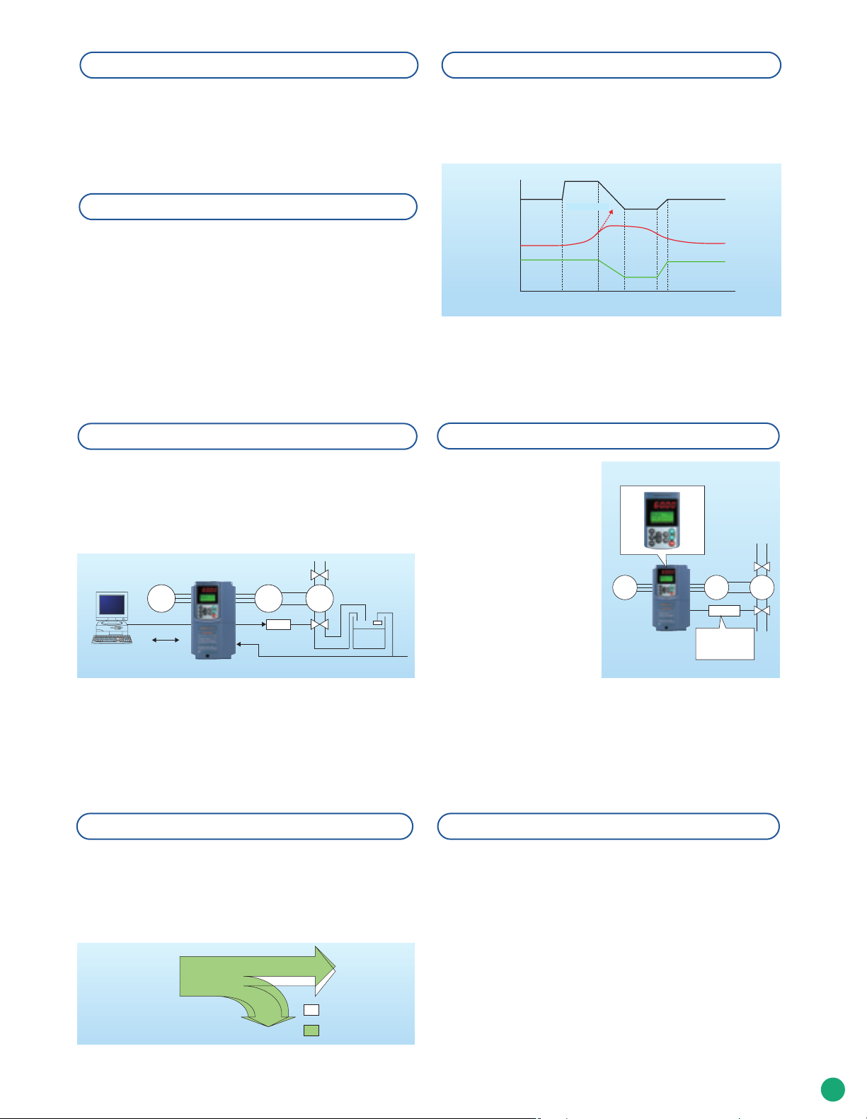
Improved capability for handling regenerated energy
When the inverter slows down and stops the motor, if the braking energy
regenerated by the motor exceeds the braking capacity of the inverter's
main circuit capacitor, the inverter will trip. At such a time, if even a little
excess energy trips the inverter, using this function you may be able to
absorb the excess braking energy without connecting to a braking resistor.
Other convenient functions
●Motor condensation prevention function
Prevents condensation of the motor from occurring in cases
where the surrounding temperature changes suddenly while the
motor is stopped.
●Motor speed display with percent
The inverter's keypad displays the operating frequency (Hz) or
Braking energy
during deceleration
Motor loss
Inverter single
unit
:
H71"0" (Disable)
: H71"1" (Enable)
the motor's rotational speed (r/min), but it can also display the
maximum speed as 100%, so it is easy to get a grasp of the
equipment's operating state.
5
Page 6
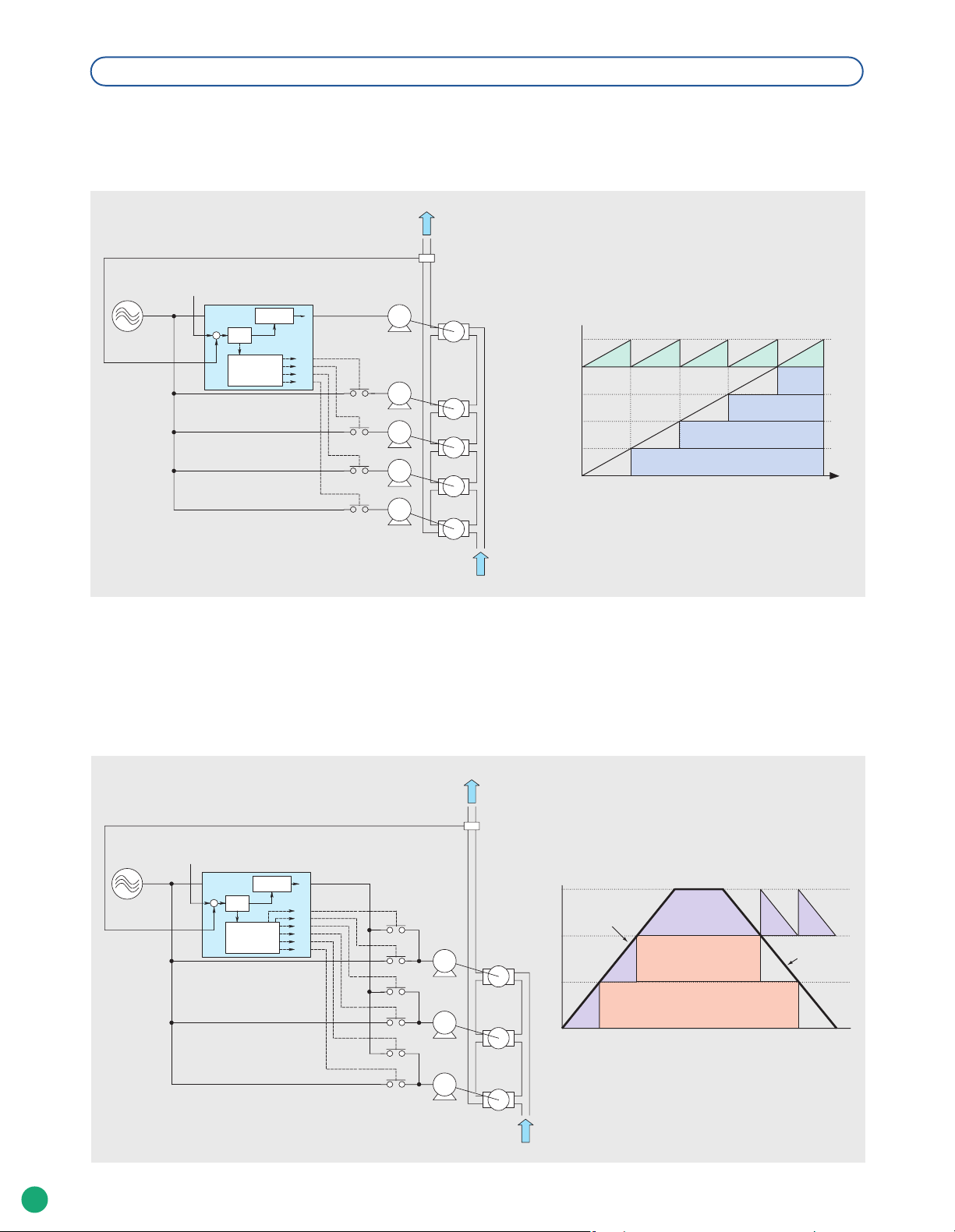
Dynamic Rotation of Pump Motors
●With a fixed inverter-driven motor
This configuration consists of a motor driven by the inverter (M0) and motors driven by commercial power (M1 to M4).
The inverter-driven motor is fixed at M0 and is controlled for variable speed. When the inverter-driven motor M0 alone cannot sustain
the desired discharge flowrate, the inverter starts one or more motors driven by commercial power as necessary.
Pressure Sensor
Pressure Command
Accl/Decel
Controller
M1_L
M2_L
M3_L
M4_L
U
V
W
M0
M1
M2
Pump
Pump
Pump
Inverter-driven
Motor
Commercial
Power-driven
Motors
Profile of Motor Operation
M0
M4
M3
M2
Mount (M2_L: ON)
Mount
(M4_L: ON)
Mount (M3_L: ON)
Feedback
L1/R
L2/S
L3/T
Inverter
PID
Cont.
Pump
Controller
M3
M4
Pump
Pump
M1
Mount (M1_L: ON)
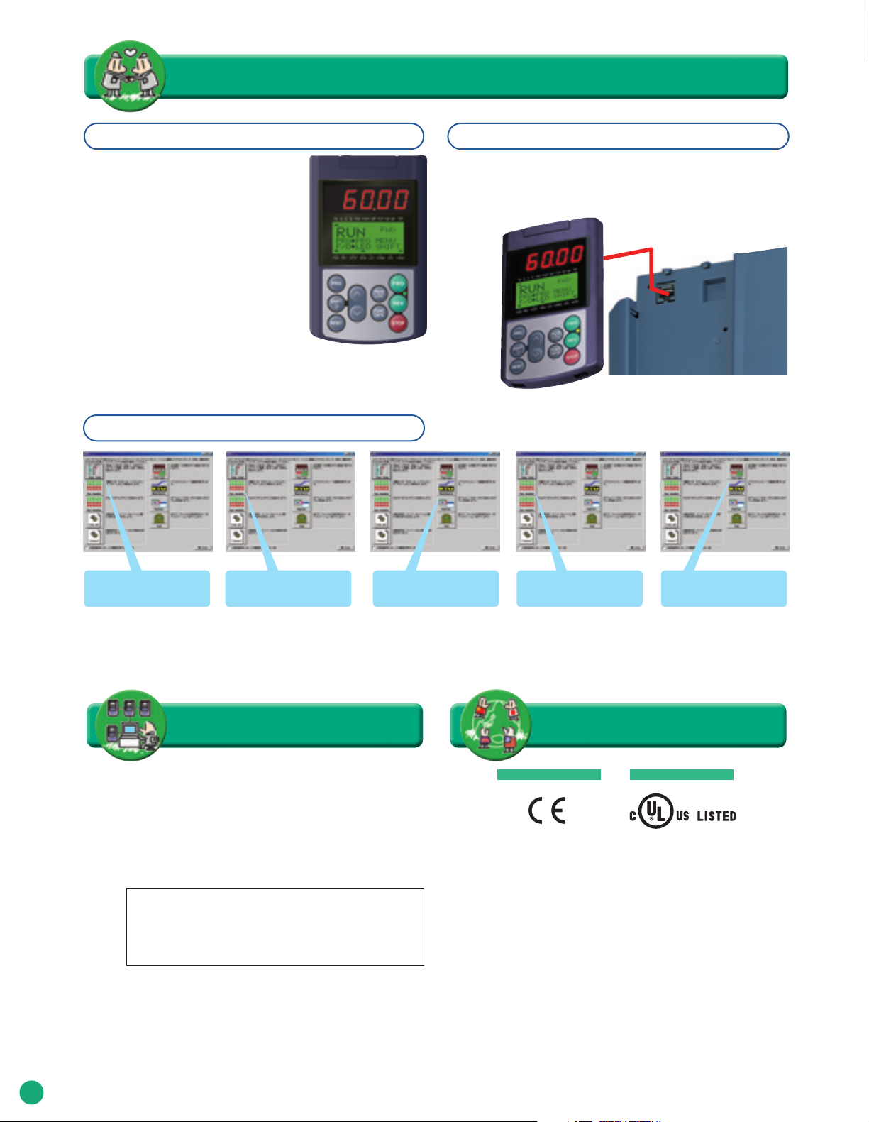
●With a floating inverter-driven motor
In this configuration, all the motors can be driven by the inverter or commercial power. At the start of operation,
each motor is driven by the inverter and is controlled for varying speed. When the first motor alone cannot sustain the desired
discharge flowrate, it is switched to commercial-power operation, and the inverter drives the second motor.
Pressure Sensor
Feedback
Pressure Command
L1/R
L2/S
L3/T
Inverter
PID
Cont.
Pump
Controller
Accl/Decel
Controller
M1_I
M1_L
M2_I
M2_L
M3_I
M3_L
U
U
V
V
W
Discharge
M3
Flowrate
M1
Pump
M2
Profile of Motor Operation
Inverter-driven
Commercial
Power-driven
Discharge
Flowrate
Discharge
Flowrate
Commercial
Power-driven
M2
M3
M1
Pump
Pump
6
Page 7

Consideration of the surrounding environment and panel design
!
Side-by-side installation saves space!
If multiple inverter units are to be used in a panel and the panel is
designed accordingly, it is possible to mount these inverters side-byside horizontally, so the panel can be designed to take up less
space. (5HP for 208V,7.5HP for 460V or smaller capacity inverters)
10.24
(260)
5.91 (150) 5.91 (150)
5.91 (150)
Units: inch (mm)
Example: 3-phase 230V,
7.5HP devices are shown.
Built-in charging resistors (in rush current suppressing resistors) help reduce peripheral equipment sizing!
When the FRENIC-Eco series (Fuji's FRENIC-Mini Series and 11 Series) is used, the charging resistors (in rush current suppressing
resistors) built into the inverter as standard equipment suppress in rush current when motors are started, so compared to operation of
motors with direct input, peripheral equipment with reduced capacity can be selected.
Cooling outside the panel is made possible by an external cooling attachment!
Use of the external cooling attachment (optional on 30HP for 208V, 40HP for 460V or smaller inverters and standard on 40HP for
208V, 50HP for 460V or larger inverters) to cool the inverter outside the panel makes it possible to install a simple cooling system
outside the panel.
7
Page 8
Operator-friendly features
!
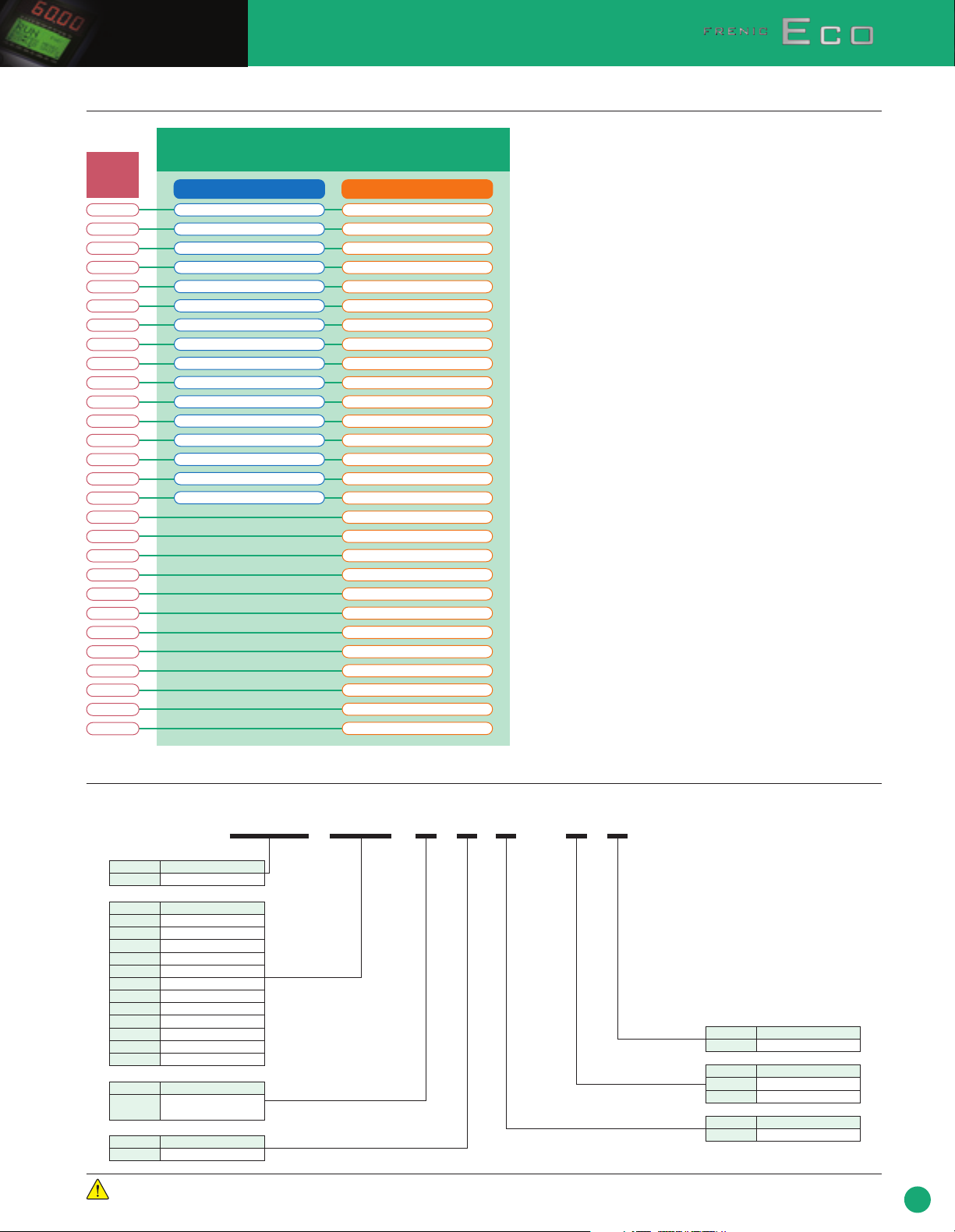
A multi-function keypad is available as standard.
● Includes an easier to see LCD with backlight.
● It has a large 7-segment, 5-digit LED display.
●
It is possible to add and delete quick setup items.
● A remote/local key has been added.
Copying up to 3 sets of data is possible.
●
Personal computer loader software
A keypad that enables remote operation is standard equipment.
The standard keypad has a decorative cover on the bottom that can
be slid sideways and removed. A LAN cable can be used to connect
the panel, making it possible to use it as a remote operation keypad.
Store, manage and
verify settings data.
Monitoring Real-time tracing
Network compatibility
● RS-485 communication is standard.
Selectable from Modbus-RTU, Metasys-N2,
FLN P1.
● It is compatible with the following networks by
inserting the option card.
• Device Net
• LONWORKS Network
• PROFIBUS-DP
• BACnet (available soon)
!
Maintenance
Information
Global compatibility
European Union North America/Canada
● Compliance with standards
● Synk/source switchable
● Wide voltage range
●
Multi-function keypad displaying multiple languages
(Japanese, English, German, French, Spanish,
Italian)
Operation
!
UL Standards (cUL certified)EC Regulation (CE mark)
8
Page 9
Model Variations
Model List
Applicable
motor rating
(HP)
1
2
3
5
7.5
10
15
20
25
30
40
50
60
75
100
125
150
200
250
300
350
400
450
500
600
700
800
900
Standard type
Three-phase 208V Three-phase 460V
FRN001F1S-2U
FRN002F1S-2U
FRN003F1S-2U
FRN005F1S-2U
FRN007F1S-2U
FRN010F1S-2U
FRN015F1S-2U
FRN020F1S-2U
FRN025F1S-2U
FRN030F1S-2U
FRN040F1S-2U
FRN050F1S-2U
FRN060F1S-2U
FRN075F1S-2U
FRN100F1S-2U
FRN125F1S-2U
FRN001F1S-4U
FRN002F1S-4U
FRN003F1S-4U
FRN005F1S-4U
FRN007F1S-4U
FRN010F1S-4U
FRN015F1S-4U
FRN020F1S-4U
FRN025F1S-4U
FRN030F1S-4U
FRN040F1S-4U
FRN050F1S-4U
FRN060F1S-4U
FRN075F1S-4U
FRN100F1S-4U
FRN125F1S-4U
FRN150F1S-4U
FRN200F1S-4U
FRN250F1S-4U
FRN300F1S-4U
FRN350F1S-4U
FRN400F1S-4U
FRN450F1S-4U
FRN500F1S-4U
FRN600F1S-4U
FRN700F1S-4U
FRN800F1S-4U
FRN900F1S-4U
How to read the model number
FRN 007 F 1 S - 2 U
Code
FRN
Code
001
002
003
005
007
010
015
020
~
700
800
900
Code
F
Code1Developed inverter series
Caution
Series name
FRENIC series
Applicable motor rating [HP]
1HP
2HP
3HP
5HP
7.5HP
10HP
15HP
20HP
~
700HP
800HP
900HP
Application range
Fans and pumps
(For variable torque load)
1
Use the contents of this catalog only for selecting product types and models. When using a product, read the Instruction Manual
beforehand to use the product correctly.
Code
U
Code
2
4
Code
S
Standard type(IP20/IP00)
Version/Manual
USA/English
Input power supply
3-phase 208V
3-phase 460V
Structure
9
Page 10
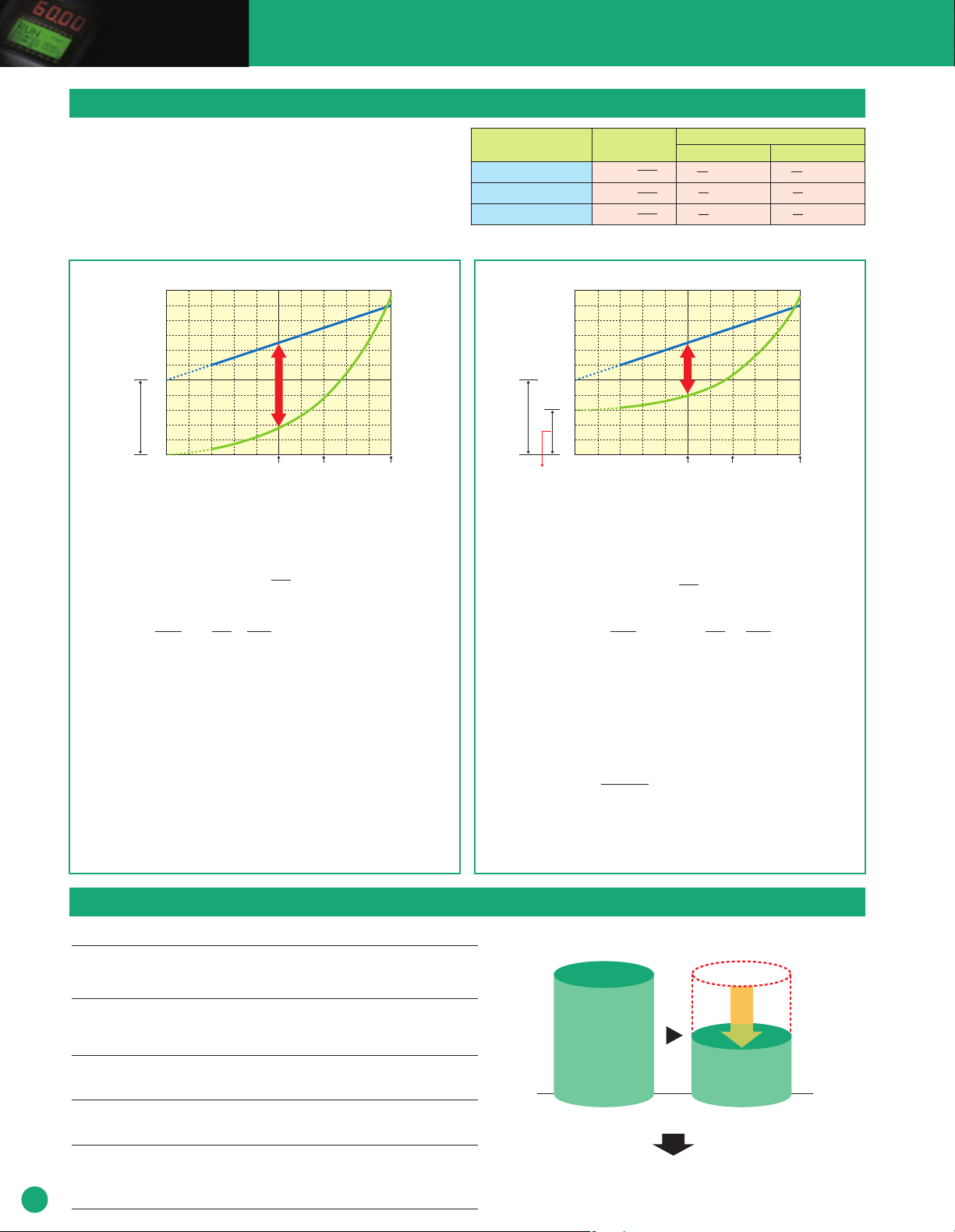
Energy Savings with an Inverter
How does using an inverter save me energy?
●
If you run a fan or pump and you have damper (valve) control or control it with
an inverter, the relation between the air flow (flow rate) and the required
power, as well as the relation between the power supply frequency fs (Hz) and
operating frequency with the inverter fINV (Hz) are as shown in the table at
right.
●
If the air flow rate is low, the energy saving effect is particularly great.
Formula (theoretical) for calculating the energy savings effect achieved by an inverter
■
Item
Air flow or flow rate Q [m3/min]
Head H (m) or pressure H [Pa]
Shaft power or power consumption P [W]
Note 1: Power supply frequency fs (Hz); operating frequency with the inverter fINV (Hz) Note 2: When fs = 50 (Hz)
Relation between fs (Hz)
and fINV (Hz) (Note 1)
fINV
Q ∝
( )
fS
fINV
H ∝
( )
fS
fINV
P ∝
( )
fS
Examples with actual numbers (Note 2)
f
INV=
45[Hz] (10%DOWN) f
45
Q =
•
Q = 0.9
•
2
•
H = 0.81
3
•
P =
0.729
Q
•
H
•
P
50
2
45
H =
( )
50
3
45
P =
( )
50
INV=
30[Hz] (40%DOWN)
30
Q =• Q = 0.6
H =• H = 0.36
( )
P =
( )
•
50
2
30
50
3
30
•
P =
0.216
50
Q
•
H
•
P
●Fan equipment
[%]
100
Air flow rate control using a damper
Energy
50
Power consumption (motor capacity)
Damper reduction rate B
0
■Energy savings effect in monetary terms: Ms ($/year)
Power charges
=-
[$/year] at the time the
damper was used
■Power charges when a damper is used: Mo [$/year]
= (P × (1 - B) × Q + P × B) × × D × H × M
■Power charges when an inverter is used: MINV [$/year]
( ( ) )
P: Motor capacity (kW)
B: Damper reduction rate (%)
Q: Air flow (%)
RUN
: Inverter operating frequency (Hz)
F
s
: Power supply frequency (Hz)
F
(Note 1) The air flow rate Q (%) shows the air flow when the damper is closed (%). The operating
frequency fRUN (Hz) when using an inverter is being proportional to the air flow Q (%), so decide on
a fRUN (Hz) value so that the relationship Q (%) = frun (Hz)/fs (Hz) is established.
For example, if air flow Q: 60 (%) = Power supply frequency fs: 50 (Hz)
Q (%) = f
60 (%) = frun (Hz) / 50 (Hz) → frun (Hz) = 50 (Hz) x 0.6 = 30 (Hz)
(Note 2) The air flow rate Q (%)does not show the damper's opening angle, but rather the air flow (%) at
the point when the opening angle is adjusted from the damper's fully open state. Depending on
the type of damper, there may not be a proportional relation between the opening angle and the
air flow, so exercise caution.
3
fRUN
fS
run (Hz) / fs (Hz)
1
η
M
savings
effect
Air flow rate control with an inverter
Operation frequency
RUN
[Hz]
f
Frequency (Air flow rate Q)
Power supply frequency
s
[Hz]
f
[Hz] ([%])
Power charges MINV
when an inverter is
used [$/year]
1
η
M
1
η
INV
D
: Annual operating days (day/year)
H: Operating hours per day (h/day)
M: Power charge unit price ($/kWh)
ηM
: Motor efficiency (%)
ηINV
: Inverter efficiency (%)
●Pump equipment
[%]
100
Air flow rate control using a valve
Energy
savings
50
Power consumption (Motor capacity)
Valve reduction rate B
0
Actual head rate A
(Ineffective portion due
to the actual head)
■Monetary amount of energy savings effect: Ms [$/year]
Power charge Mv
($/year) when a valve
=
is used
■Power charge when a valve is used: Mv [$/year]
Frequency (Air flow rate Q)
-
= (P × (1 - B) × Q + P × B) × × D × H × M
■Power charge when an inverter is used: MINV [$/year]
= P - P × A × +P×A × × × D × H × M= P × × × × D × H × M
(( ) ( ) )
P: Motor capacity (kW)
A: Actual head rate (%)
B: Valve reduction rate (%)
Q: Flow rate (%)
RUN
: Inverter operating frequency (Hz)
F
s
: Power supply frequency (Hz)
F
(Note 1) The actual head rate A (%) is determined by the pump's load characteristics and is a rate that the power
consumption (motor capacity) is multiplied by.
See the following calculation formula.
Actual head rate A (%) =
Loss head (m)
(Note 2) The flow rate Q (%) value shows a volume (%) when the flow rate is restricted by the closing of the valve.
The operating frequency when an inverter is used f
on a f
RUN
(Hz) so that the relationship Q (%) = f
For example, if the flow rate Q: 50 (%) and the power supply frequency f
60 (%) = f
run
(Note 3) The flow rate Q (%) does not show the valve's opening angle, but rather the flow rate (%) at the point when
(Hz) / 50 (Hz) → f
the opening angle is adjusted from the valve's fully open state. Depending on the type of valve, there may
not be a proportional relation between the opening angle and the flow rate, so exercise caution.
3
fRUN
fS
Actual head (m)
RUN
(Hz) = 50 (Hz) x 0.6 = 30 (Hz)
effect
Air flow rate control using an inverter
Operation frequency
fRUN [Hz]
Power supply frequency
fs [Hz]
[Hz] ([%])
Power charge MINV
[$/year] when an
inverter is used
1
η
M
1
η
M
s
is 50Hz, Q (%) = f
1
INV
RUN
(Hz) / fs (Hz)
η
D: Annual operating days (day/year)
H: Operating hours per day (h/day)
M: Power charge unit price ($/kWh)
ηM
: Motor efficiency (%)
ηINV
: Inverter efficiency (%)
RUN
(Hz) is proportional to the flow rate Q (%), so decide
run
(Hz) / fs (Hz) can be established.
Energy Savings effect of replacing damper (valve) control with inverter control
Example: The energy savings effect on an office's air conditioning equipment if the operating pattern is as follows: Air flow: 85% for 2,000 hrs, and 60% for 2,000 hrs.Total 4,000 hrs/year. Motor output is 15kW x 1 unit.
10
●
Under damper (valve) control,
(15kW x 91% x 2,000 hrs.) + (15kW x 76% x 2,000 hrs.) =
Air flow rate 85% Air flow rate 60%
●
If an inverter is used
(15kW x 61% x 2,000 hrs.) + (15kW x 22% x 2,000hrs.) =
Air flow rate 85% Air flow rate 60%
●
The power saving effect
and the motor's rotational speed is controlled, the required power is as follows:
when the power charges are $0.087/kWh is
25,200kWh x $0.087 =
●
The amount of time it takes to amortize the equipment cost if the inverter's cost is $2,348 is
$2,348 / $2,192 =
●
Also, if we let the CO2 emissions coefficient be 0.12 kg/kWh (environmental statistics from the Environmental Department of
the Environmental Agency)
,
the annual CO2 reduction
25,200kWh x 0.12 kg/kWh =
the required power is as follows:
50,100kWh
24,900kWh
$2,192/year
1.1 years
amounts to
3,024kg/year
50,100kWh
Damper (valve) control Inverter control
Energy savings effect
50,100kWh - 24,900kWh =
24,900kWh
25,200kWh/year
Page 11
Examples of measurements with actual equipment
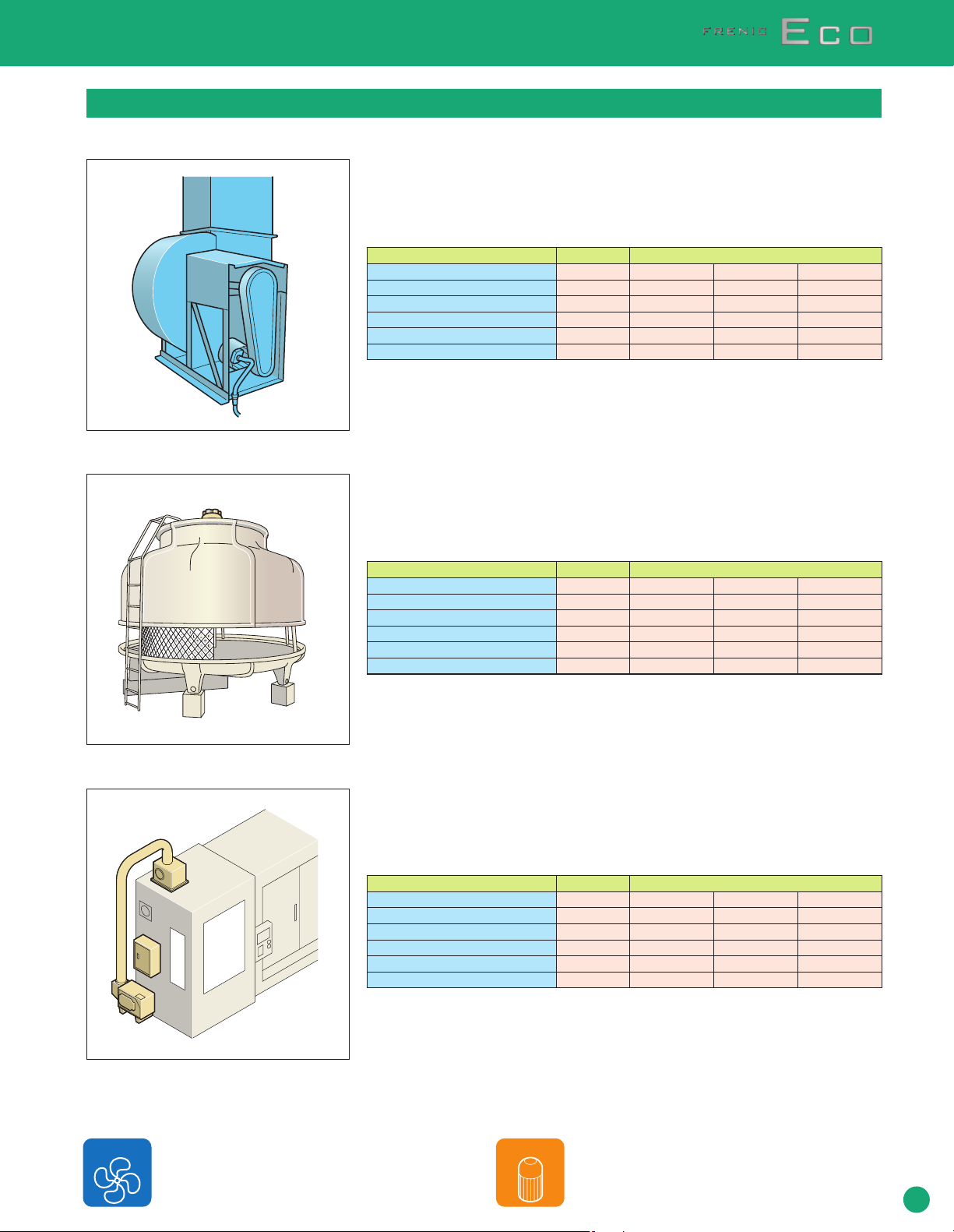
■Exhaust fan (generating variable torque load)
●Motor capacity and inverter capacity
•
Motor capacity : 30HP
•
Inverter model : FRN030F1S-2U
•
DC REACTOR : DCR2-22A
●Power reduction rate and energy saving effect amount
Item Inverter-controlled operation
Operation frequency (Hz)
Average power use (kW)
Power reduction rate (%)
Annual power charge ($)
Annual amount ($) of energy saving effect
Annual CO2 reduction volume (kg/year)
●Operating conditions
•
Annual operating days : 310 (days/year)
•
Working hours per day : 24 (hrs/day)
•
Power charge unit price : $0.087/kWh
■Cooling tower (generating variable torque load)
●Motor capacity and Inverter capacity
•
Motor capacity : 7.5HP
•
Inverter model : FRN007F1S-2U
•
DC REACTOR : DCR2-5.5
●Power reduction rate and energy saving effect amount
Item
Operation frequency (Hz)
Average power use (kW)
Power reduction rate (%)
$
Annual power charge (
Annual amount ($) of energy savings effect
Annual CO2 reduction volume (kg/year)
)
Operation using commercial power
50
17.2
-
11,133
-
-
Operation using commercial power
60
5.18
-
2,703
-
-
45
13.1
▲30.7
8,479
2,653
3,660
Inverter-controlled operation
45
2.31
▲55.4
1,205
1,506
2,066
40
9.10
▲47.1
5,890
5,242
7,232
40
1.63
▲68.5
850
1,851
2,556
35
6.23
▲63.8
4,032
7,096
9,794
35
1.10
▲78.8
574
769
2,938
●Operating conditions
•
Annual operating days : 300 (days/year)
•
Working hours per day : 20 (hrs/day)
•
Power charge unit price : $0.087/kWh
■Mist collector (generating variable torque load)
●Motor capacity and Inverter capacity
•
Motor capacity : 5HP
•
Inverter Model : FRN005F1S-2U
•
DC REACTOR : DCR2-3.7
●Power reduction rate and energy saving effect amount
Item
Operation frequency (Hz)
Average power use (kW)
Power reduction rate (%)
Annual power charge ($)
Annual amount ($) of energy savings effect
Annual CO2 reduction volume (kg/year)
Operation using commercial power
60
3.27
-
1,479
-
-
Inverter-controlled operation
45
1.44
▲56.0
651
827
1,142
40
0.99
▲69.7
447
1,029
1,423
35
0.69
▲78.9
312
1,166
1,610
●Operating conditions
•
Annual operating days : 260 (days/year)
•
Working hours per day : 20 (hrs/day)
•
Power charge unit price : $0.087/kWh
Conduct a search. You can study energy savings with the following types of equipment.
Fan systems
• Air conditioning fans
•
Dust collectors
•
Exhaust fans
•
AHU
•
Mist -collectors
Pump systems
• Package air conditioners, etc.
•
Cooling water pumps
•
Cleaning pump
•
Coolant pumps
•
Circulating pumps
•
Roots blowers
• Water cooler pumps, etc.
11
Page 12
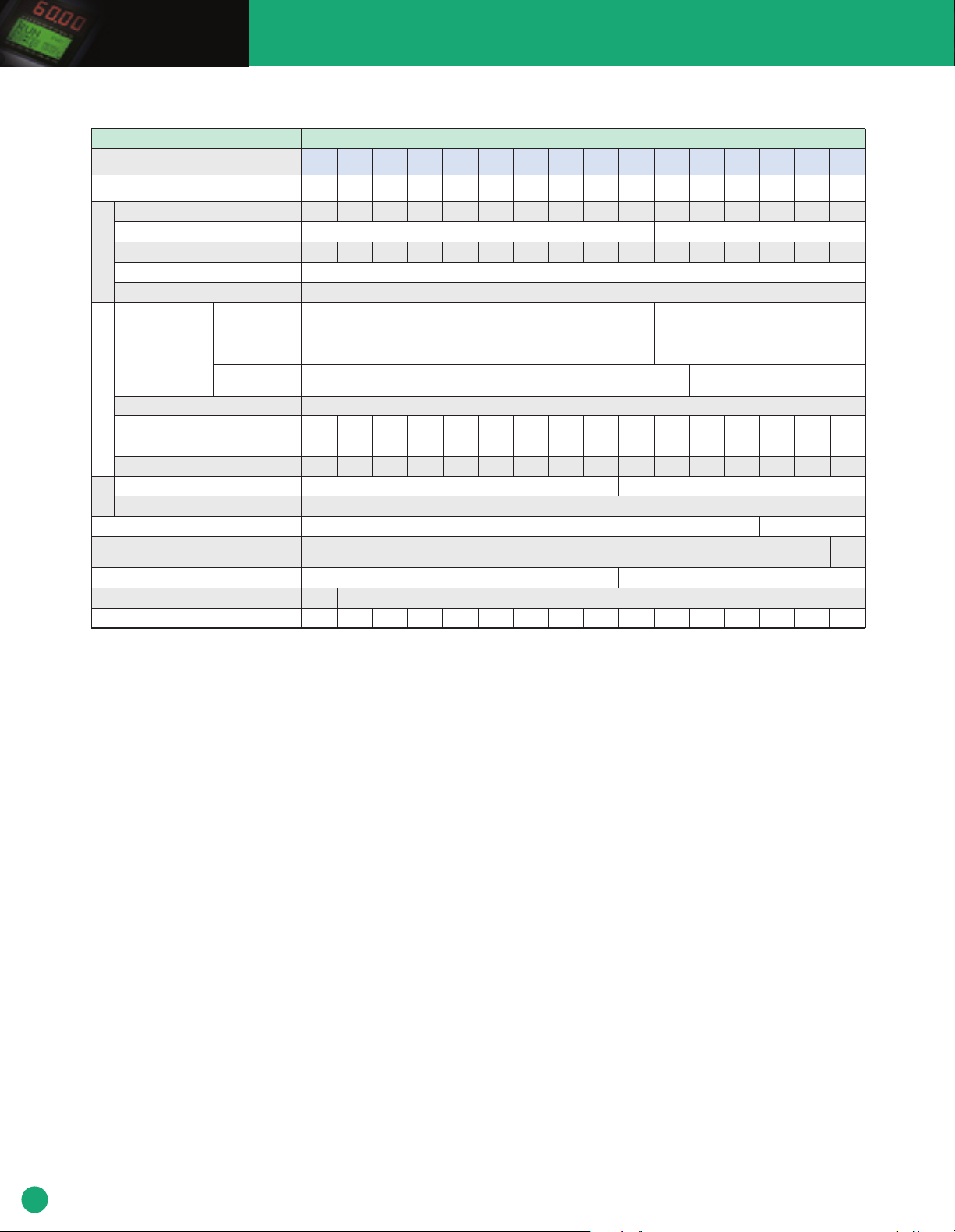
Standard specifications
■ Three-phase 208V
Item Specifications
Type (FRN
Nominal applied motor [HP]
Rated capacity [kVA]
Rated voltage [V]
Rated current [A]
Overload capability
Output ratings
Rated frequency
Phases,
voltage,
frequency
Voltage/frequency variations
Input ratings
Rated current [A]
Required power supply capacity [kVA]
Torque [%]
DC injection braking
Braking
DC reactor (DCR)
Applicable safety standards
Enclosure (IEC60529)
Cooling method
Mass [lbs(kg)]
*1 Standard 4-pole motor
2
Rated capacity is calculated by assuming the output rated voltage as 208V for three-phase 208V.
*
3
Output voltage cannot exceed the power supply voltage.
*
4
An excessively low setting of the carrier frequency may result in the higher motor temperature or tripping of the inverter by its overcurrent limiter setting. Lower the continuous load or maximum load
*
instead. (When setting the carrier frequency (F26) to 1kHz, reduce the load to 80% of its rating.)
5
Use [R1,T1] terminals for driving AC cooling fans of an inverter powered by the DC link bus, such as by a high power factor PWM converter. (In ordinary operation, the terminals are not used.)
*
6
Calculated under Fuji-specified conditions.
*
7
Obtained when a DC reactor (DCR) is used.
*
8
Average braking torque (Varies with the efficiency of the motor.)
*
9
*
Voltage unbalance (%) = x 67 (IEC61800-3 (5.2.3))
If this value is 2 to 3%, use an AC reactor (ACR).
F1S-2U )
Main power supply
Auxiliary control
power input
Auxiliary fan
power input
(with DCR)
6
*
(without DCR)
Max. voltage (V) - Min. voltage (V)
Three-phase average voltage (V)
003
005
007
010
015
020
025
030
040
050
060
075
75
76
211
199
-
72
Standard
90
(41)
100
100
273
270
90
(41)
001
002
1
1.6
7.1
4.6
3.1
5.1
1.2
2
2.7
7.5
5.8
9.1
2.2
Fan cooling
7.3
(3.3)
3
3.8
10.6
8.7
12.9
3.2
7.3
(3.3)
5
7.5
10
15
20
25
30
40
6.0
9.0
11
16
21
27
31
41
16.7
25
31
47
60
75
88
114
Three-phase, 200 to 220V, 50Hz
Three-phase, 200 to 230V, 60Hz
Single-phase, 200 to 230V, 50/60Hz
9
, Frequency: +5 to -5%
14.5
20.6
27.5
41.3
55.1
68.8
82.6
109
21.5
30.8
40.8
59.4
76.6
94.0
110
144
5.3
7.5
10
15
20
25
30
20.0 10 to 15
IP00, UL open type
7.5
13
13
(3.4)
(5.8)
15
(6.0)
(6.9) 21 (9.7) 21 (9.7)
25
(11.5) 51 (23)
60
50
60
51
169
143
Single-phase, 200 to 220V, 50Hz
Single-phase, 200 to 230V, 60Hz
134
160
179
215
40
49
58
73
75
(33)
(34)
1
*
2
*
Three-phase, 200V to 240V (With AVR function) Three-phase, 200V to 230V (With AVR function)
3
*
4
*
120% of rated current for 1min.
50, 60 Hz
Three-phase, 200 to 240V, 50/60Hz
Single-phase, 200 to 240V, 50/60Hz
5
None
*
Voltage: +10 to -15% (Voltage unbalance 2% or less) *
7
*
8
*
Starting frequency: 0.0 to 60.0Hz, Braking time: 0.0 to 30.0s, Braking level: 0 to 60%
Option
UL508C, C22.2 No.14, EN50178-1997
IP20, UL open type
Natural
cooling
(3.2)
98
-
98
125
125
123
343
333
-
120
UL508C
C22.2 No.14
265
(120)
12
Page 13
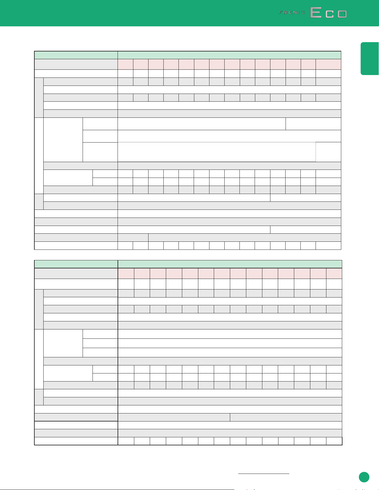
■ Three-phase 460V
●1 to 75HP
Item Specifications
Type (FRN
Nominal applied motor [HP]
Rated capacity [kVA]
Rated voltage [V]
Rated current [A]
Overload capability
Output ratings
Rated frequency
Phases,
voltage,
frequency
Input ratings
Voltage/frequency variations
Rated current [A]
Required power supply capacity [kVA]
Torque [%]
DC injection braking
Braking
DC reactor (DCR)
Applicable safety standards
Enclosure (IEC60529)
Cooling method
Mass [lbs(kg)]
●100 to 900HP
Type (FRN
Nominal applied motor [HP]
Rated capacity [kVA]
Rated voltage [V]
Rated current [A]
Overload capability
Output ratings
Rated frequency
Phases,
voltage,
frequency
Voltage/frequency variations
Input ratings
Rated current [A]
Required power supply capacity [kVA]
Torque [%]
DC injection braking
Braking
DC reactor (DCR)
Applicable safety standards
Enclosure (IEC60529)
Cooling method
Mass [lbs(kg)]
*1 Standard 4-pole motor
2
*
Rated capacity is calculated by assuming the output rated voltage as 460V for three-phase 460V.
*3 Output voltage cannot exceed the power supply voltage.
4
*
An excessively low setting of the carrier frequency may result in the higher motor temperature or
tripping of the inverter by its overcurrent limiter setting. Lower the continuous load or maximum load
instead. (When setting the carrier frequency (F26) to 1kHz, reduce the load to 80% of its rating.)
F1S-4U )
Item
F1S-4U )
Main power supply
Auxiliary control
power input
Auxiliary fan
power input
(with DCR)
6
*
(without DCR)
Main power supply
Auxiliary control
power input
Auxiliary fan
power input
(with DCR)
6
*
(without DCR)
001 003 005 010002 007 015 020 025 030 040 050 060
1
*
2
*
Three-phase, 380 to 480V (With AVR function)
3
*
4
*
120% of rated current for 1min.
50, 60 Hz
Three-phase, 380 to 480V, 50/60Hz
Single-phase, 380 to 480V, 50/60Hz
5
None
*
Voltage: +10 to -15% (Voltage unbalance 2% or less) *9, Frequency: +5 to -5%
7
*
8
*
Starting frequency: 0.0 to 60.0Hz, Braking time:0.0 to 30.0s, Braking level: 0 to 60%
Option
UL508C, C22.2 No.14, EN50178-1997
IP20, UL open type
Natural cooling
(3.1)
1
*
2
*
3
Three-phase, 380 to 480V (With AVR function)
*
4
*
120% of rated current for 1min.
50, 60 Hz
Three-phase, 380 to 440V, 50Hz
Three-phase, 380 to 480V, 60Hz
Single-phase, 380 to 480V, 50/60Hz
Single-phase, 380 to 440V/50Hz
5
Single-phase, 380 to 480V/60Hz
*
Voltage: +10 to -15% (Voltage unbalance 2% or less)
7
*
8
*
Starting frequency: 0.0 to 60.0Hz, Braking time:0.0 to 30.0s, Braking level: 0 to 60%
Standard
UL508C, C22.2 No.14, EN50178-1997
IP00, UL open type
Fan cooling
2
1
2.9
1.9
3.7
2.5
2.5
1.3
4.8
2.5
2.0
1.1
7.1
(3.2)
125
125
133
168
140
-
112
Fan cooling
6.8
100
100
110
139
113
-
91
75
(34) 93 (42) 99 (45)
3
4.3
5.5
3.8
6.9
3.1
7.3
(3.3)
150
150
161
203
169
135
5
7.1
9.0
6.2
10.8
5.0
7.5
(3.4)
200
200
191
240
222
-
-
177
139
(63)
60
50
40
30
25
20
15
10
7.5
67
57
47
35
29
23
18
13
9.9
85
72
59
44
37
30
23
16.5
12.5
Three-phase, 380 to 440V,50Hz
Three-phase, 380 to 480V,60Hz
8.9
11.8
17.7
23.7
29.6
35.5
46.8
57.0
68.4
14.5
19.1
27.7
36.0
43.6
50.9
64.0
78.5
93.7
7.1
10
15
19
24
29
38
46
55
20 10 to 15
IP00, UL open type
7.5
13
(3.4)
(6.0)
13
(6.0) 15 (6.9)
22
22
(9.9)
(9.9) 25(11.5) 51(23) 53(24)
Specifications
300
250
250
240
302
275
-
220
212
(96)
*5
Use [R1,T1] terminals for driving AC cooling fans of an inverter powered by the DC link bus, such
as by a high power factor PWM converter. (In ordinary operation, the terminals are not used.)
6
Calculated under Fuji-specified conditions.
*
7
*
Obtained when a DC reactor (DCR) is used.
8
*
Average braking torque (Varies with the efficiency of the motor.)
9
Voltage unbalance (%) = x 67 (IEC61800-3(5.2.3))
*
If this value is 2 to 3%, use an AC reactor (ACR).
350
300
350
286
330
360
415
*9, Frequency: +5% to -5%
382
330
-
-
305
263
10 to 15
212
216
(96)
(98)
(162)
400
450
500
400
450
500
380
414
517
477
520
650
440
495
545
-
-
-
351
395
435
UL508C, C22.2 No.14
357
357
529
(162)
(240)
Max. voltage (V) - Min. voltage (V)
Three-phase average voltage (V)
600
600
589
740
652
-
520
529
(240)
700
700
669
840
756
-
603
783
(355)
075
75
83
105
Single-phase,
380 to 440V/50Hz,
Single-phase,
380 to 480V/60Hz
85.7
118
69
73
(33)
800
900
800
900
764
828
960
1040
869
981
-
-
693
782
794
794
(360)
(360)
Specifications
13
Page 14
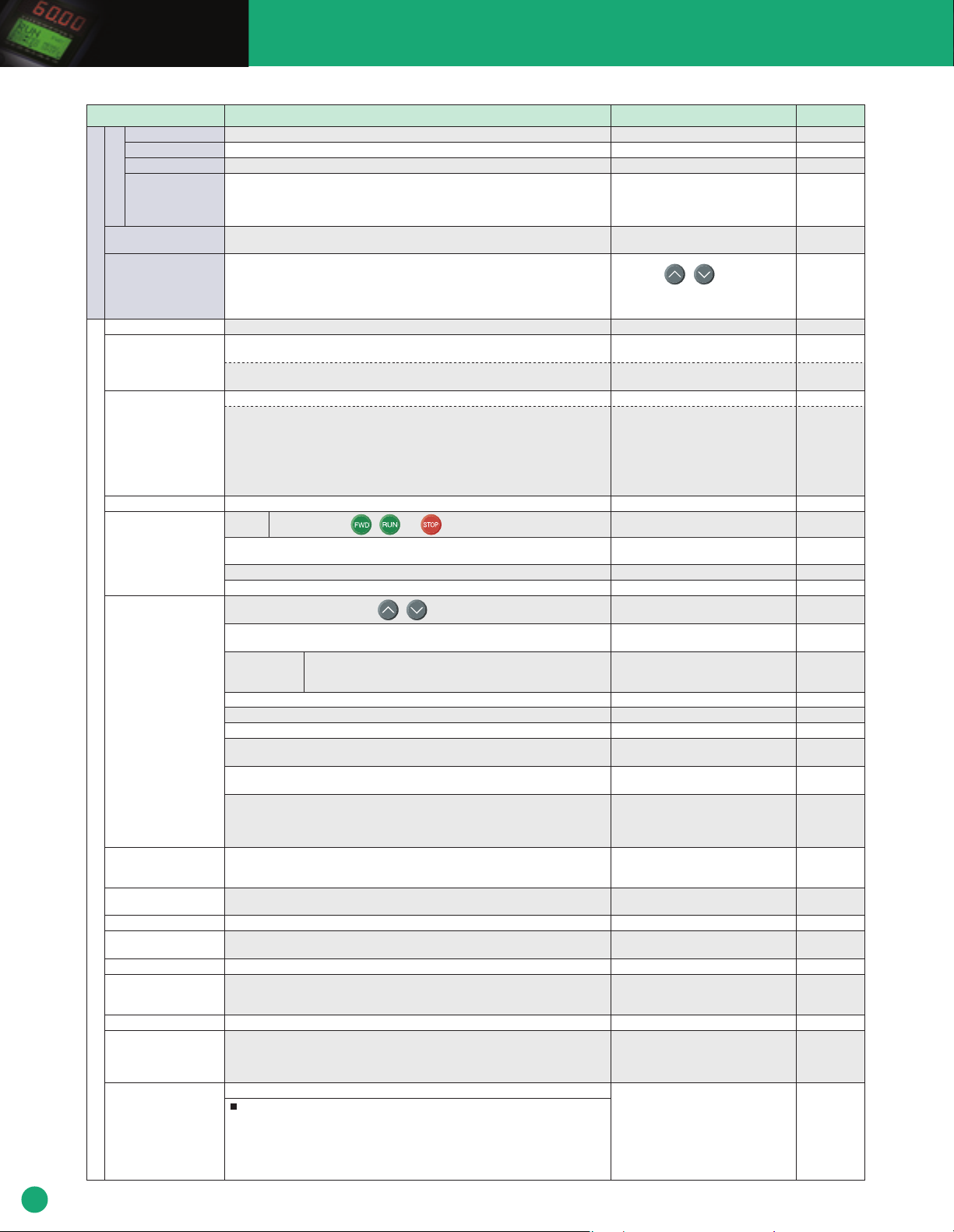
Common specifications
Item Explanation
Maximum frequency
Base frequency
Starting frequency
Carrier frequency
Setting range
Accuracy (Stability)
Setting resolution
Output frequencyControl
Control method
Voltage/freq. characteristic
(Non-linear V/f setting)
Torque boost
(Load selection)
Starting torque
Start/stop
Frequency command
source
Acceleration/ deceleration
time
Frequency limiter
Bias frequency
Gain for frequency setting
Jump frequency setting
Restart after momentary
power failure
Current limit
Line/inverter switching
PID control
25 to 120Hz
25 to 120Hz
0.1 to 60.0Hz
• 0.75 to 15kHz (208V/460V: 1 to 25HP for 208V and 1 to 30HP for 460V)
• 0.75 to 10kHz (208V/460V: 30 to 100HP for 208V and 40 to 100HP for 460V)
• 0.75 to 6kHz (208V/460V: 125HP for 208V and 125 to 900HP for 460V)
• Analog setting: ±0.2% of maximum frequency (at 25±10
• Keypad setting: ±0.01% of maximum frequency (at -10 to +50˚C (14 to 122˚F))
• Analog setting: 1/1000 of maximum frequency (ex. 0.06Hz at 60Hz, 0.12Hz at 120Hz)
• Keypad setting: 0.01Hz (99.99Hz or less), 0.1Hz (100.0Hz or more)
• Link setting: Selectable from 2 types
эээээ
эээээ
V/f control
Possible to set output voltage at base frequency and at maximum output frequency (common spec.).
AVR control can be turned ON or OFF.
1 point (Arbitrary voltage and frequency can be set.)
Torque boost can be set with the function code F09.
Select application load type with the function code F37.
0: Variable torque load
1: Variable torque load (for high starting torque)
2: Auto-torque boost
3: Auto-energy-saving operation (variable torque load in acceleration/deceleration)
4:
5: Auto-energy-saving operation (auto-torque boost in acceleration/deceleration)
50% or over
Keypad
operation
External signals : Forward (reverse) rotation, stop command(capable of 3-wire operation),
(7 digital inputs)
Link operation: Operation through RS-485 communication and Field Bus communication (option)
Operation command switching: Remote/local switch, link switch, second operation command switch
Keypad operation: Can be set with / keys.
External potentiometer(1 to 5k
Analog input Can be set with external voltage/current input.
Multistep frequency :
UP/DOWN operation : The frequency rises or lowers while the digital input signal is turned on.
Link operation : Can be set with RS-485 communications and field bus communications (option).
Frequency setting change :
Auxiliary frequency : Inputs at terminal [12],[C1] or [V2] can be added to the main setting
setting
Inverse operation
the normal and inverse operations.
0 to 3600s
• Acceleration and deceleration pattern can be selected from 4 types: Linear, S-curve
(weak), S-curve (strong), Curve (constant output max. capacity).
• Shutoff of the operation command coasts the motor to decelerate and stop.
High and low limiters can be set (setting range: 0 to 120Hz)
Bias of set frequency and PID command can be set in the range between 0 and ±100%.
The analog input gain can be set in the range from 0 to 200%.
Three operation points and their common jump hysteresis width (0 to 30Hz) can be set.
• The inverter restarts upon recovery from power failure without stopping the motor.
• In the "operation continuation mode," recovery of the power supply is waited for while the output frequency slightly drops.
• Selection can be made among starting at 0Hz, starting at the frequency immediately before the momentary
power failure, and starting at the frequency specified in the starting mode after power recovery.
Keeps the current under the preset value during operation.
•
Line/inverter switching (starting at line frequency) can be made with a digital input signal (SW50, SW60).
•
A built-in line/inverter switching sequence performs sequence control with a digital input signal (ISW50, ISW60) to
output a signal (SW88, SW52-1, SW52-2) for controlling an external magnetic contactor (MC). As a built-in
sequence, two types can be selected, including the one switching automatically to the line upon an inverter alarm.
Capable of PID regulator control for process
• Key operation (UP and DOWN keys): 0 to 100%
• Analog input (terminal [12],[V2]): 0 to +10V DC/0 to 100%
• Analog input (terminal [C1]): 4 to 20mA DC/0 to 100%
• UP/DOWN (digital input): 0 to 100%
• Communication (RS-485, bus option): 0 to 20,000/0 to 100%)
• 1/20000 of maximum frequency (ex. 0.003Hz at 60Hz, 0.006Hz at 120Hz)
• 0.01Hz (fixed)
Auto-energy-saving operation (variable torque load (for high starting torque) for acceleration/deceleration)
Start and stop with / and keys.
second operation command,coast-to-stop command, external alarm, alarm reset, etc.
Ω, 1/2W) : Prepared by users
0 to +10V DC (0 to +5V DC)/0 to 100% (terminal [12],[V2])
4 to 20mA DC/0 to 100% (terminal [C1])
Selectable from 8 steps (step 0 to 7)
Two types of frequency settings can be switched with an external signal (digital input). Changeover
between remote and local (keypad operation) or frequency setup through communication is also possible.
as auxiliary frequency settings.
: The digital input signal and function code setting sets or switches between
• +10 to 0V DC/0 to 100%(Terminal [12], [V2])
• 20 to 4mA DC/0 to 100%(Terminal [C1])
Process commands
C (77±50˚F))
˚
The carrier frequency may drop automatically
according to the ambient temperature or
output current to protect the inverter. This
protective operation can be canceled by
function code H98.
Setting with / keys
Three-phase 208V: 80 to 240V
Three-phase 460V: 160 to 500V
Three-phase 208V: 0 to 240V/0 to 120Hz
Three-phase 460V: 0 to 500V/0 to 120Hz
Set when 0, 1, 3, or 4 is selected at F37.
Connected to analog input terminals
Ķ13ķ, Ķ12ķ, Ķ11ķ.
E.g. : 0 to 5 VDC/1 to 5 VDC is applicable
with bias/gain for analog input.
Selection can be made between continuation of operation and
stopping at frequencies equal to or smaller than the lower limit.
Voltage signals (terminal [12],[V2]) and current
signal (terminal [C1]) can be set independently.
Remarks
Related
function code
F03
F04
F23
F26, F27, H98
F03 to F05
H50, H51
F09, F37
F09, F37
F02
E01 to E05
E98, E99
H30, y98
F01, C30
F18, C50, C32 to
C34, C37 to C39,
C42 to C44
C05 to C11
F01, C30
H30, y98
F01, C30
E61 to E63
C53
F07, F08
H07
H11
F15, F16
H63
F18, C50 to C52
C32, C34, C37,
C39, C42, C44
C01 to C04
F14
H13 to H16, H92, H93
F43, F44
J22
E61 to E63
J01 to J06
J10 to 0J19
14
Page 15

Item Explanation
PID control
Auto search for idling
motor's speed
Automatic deceleration
Deceleration characteristic
Automatic energy-saving operation
Overload protection
control
ControlIndication
Auto-tuning
Cooling fan ON/OFF control
Pump control
Running/stopping
Lifetime early warning
Cumulative run time
Output
Trip error code
Trip history
Feedback value
• Analog input (terminal [12],[V2]) :0 to +10V DC/0 to 100%
• Analog input (terminal [C1]) : 4 to 20mA DC/0 to 100%
Accessory functions
• Alarm output (absolute value alarm, deviation alarm) • Normal operation/inverse operation
• Sleep function эээээээээ • Anti-reset wind-up function
• PID output limiter • Integration reset/hold
Starting at the preset frequency, the inverter automatically searches the idling motor speed
to be harmonized and starts to drive it without stopping it.
Upon a DC link voltage exceeding the overvoltage limit level during deceleration, the
deceleration time automatically extends to avoid an trip.
The motor loss increases during deceleration to reduce the load energy regenerating at the inverter to avoid an trip upon mode selection.
The output voltage is controlled to minimize the total sum of the motor loss and inverter loss at a constant speed.
The output frequency is automatically reduced to suppress the overload protection trip of the inverter
caused by an increase in the ambient temperature or motor load, or by other operating conditions.
The motor parameters are automatically tuned.
Detects inverter internal temperature and stops cooling fan when the temperature is low.
An inverter controls multiple driving pumps at a time combining with driving sources of the inverter and commercial power.
The inverter’s integrated PID controller controls them in the flowrate, pressure and so on. The inverter controls each
member of pump control sequences issuing the power source switching signal between the inverter output and commercial
power. Two control modes are available. One is a fixed motor-driving mode where the inverter exclusively controls the
single pump. Another is a cyclic motor-driving mode where the inverter cyclically controls a member of pumps.
• Fixed motor-driving mode : Pumps under control = one inverter driven + four commercial power driven
• Cyclic motor-driving mode : Pumps under control = three inverter /commercial power driven (In this mode,
a relay output card option (OPC-F1S-RY) is required.)
Furthermore, this control features a periodic switching function, an average time drive-switching function,
a
cumulative pump run time monitor, a cumulative relay activating times monitor and so on.
• Speed monitor, output current [A], output voltage [V], torque calculation value, input power
[kW],PID reference value, PID feedback value, PID output, load factor, motor output
• Slect the speed monitor to be displayed from the following.
Output frequency [Hz], motor speed [r/min.], load shaft speed [r/min.], % indication
Shows the lifetime early warnings of the electrolytic capacitors on the printed circuit boards,
the DC link bus capacitor, and the cooling fan.
Shows the cumulative running hours of the motor and inverter, and the input watt-hour.
Transistor outputs - quantity 3
Relay outputs - quantity 1 from C and quantity 1 from A
Voltage output - 0 - 10 Vdc
Current output - 4-20 mA
Displays the cause of trip by codes.
•
(Overcurrent during acceleration)
• (Grounding fault) • (Input phase loss) • (Undervoltage)
• (Output phase loss) •
•
(Overvoltage at constant speed)
• (Inverter overheat) •
• (Inverter overload) • (Blown fuse) •
• (Memory error) •
•
(Optional communication error)
• (Tuning error) •
•
(RS-485 communication error (option))
Saves and displays the last 4 trip codes and their detailed description.
•
(Overcurrent during deceleration)
(Overvoltage during acceleration)
•
(Overheating of the heat sink)
(Motor protection (PTC thermistor))
(Keypad communication error)
• (Option error) •
(RS-485 communication error) • (Data save error due to undervoltage)
• (LSI error)
•
(Overcurrent at constant speed)
•
(Overvoltage during deceleration)
• (External alarm)
• (Motor overload)
(Charging circuit fault)
• (CPU error)
(Option action error)
Remarks
An external output is issued in a transistor
or relay output signal.
An external output can be issued in a
transistor or relay output signal.
Related
function code
E61 to E63,
J01 to J06,
J10 to J19
H69, F08
H71
F37,F09
P04
H06
E43
E48
E52
Specifications
15
Page 16

Common specifications
Item Explanation
Overcurrent protection
Short-circuit protection
Grounding fault protection
Overvoltage protection
Surge protection
Undervoltage
Input phase loss
Output phase loss
Overheating
Overload
ProtectionEnvironment
Electronic thermal
PTC thermistor
Overload early warning
Motor protection
Stall prevention
Momentary power failure protection
Retry function
Command loss detection
Installation location
Ambient temperature
5 to 95% (nocondensation)
Altitude
Vibration
Amb. temp
Amb. humidity
Storage
The inverter is stopped upon an overcurrent caused by an overload.
The inverter is stopped upon an overcurrent caused by a short-circuit in the output circuit.
The inverter is stopped upon an overcurrent caused by a grounding fault in the output circuit.
An excessive DC link circuit voltage is detected to stop the inverter.
The inverter is protected against surge voltages intruding across the main circuit power cable and ground.
Stops the inverter by detecting voltage drop in DC link circuit.
Stops or protects the inverter against input phase loss.
Detects breaks in inverter output wiring at the start of running and during running, stopping the inverter output.
The temperature of the heat sink of the inverter or that inside the inverter unit is detected to
stop the inverter, upon a failure or overload of the cooling fan.
The inverter is stopped upon the temperature of the heat sink of the inverter or the temperature of the switching element calculated from the output current.
The inverter is stopped upon an electronic thermal function setting to protect the motor.
A PTC thermistor input stops the inverter to protect the motor.
Warning signal can be output based on the set level before the inverter trips.
The output frequency decreases upon an output current exceeding the limit during acceleration or constant speed operation, to avoid overcurrent trip.
• A protective function (inverter stoppage) is activated upon a momentary power failure for 15msec or longer.
• If restart upon momentary power failure is selected, the inverter restarts upon recovery of the voltage within the set time.
When the motor is tripped and stopped, this function automatically resets the tripping state
and restarts operation.
A loss (broken wire, etc.) of the frequency command is detected to output an alarm and
continue operation at the preset frequency (set at a ratio to the frequency before detection
Shall be free from corrosive gases, flammable gases, oil mist, dusts, and direct sunlight.
[Pollution degree 2 (IEC60664-1)] Indoor use only.
o
-10 to +50
-10 to +40
C (14 to 122˚F)
o
C (14 to 104˚F) (IP54 series)
5 to 95% (no condensation)
Altitude [ft (m)]
Lower than 3300 (1000)
3301 to 6600 (1001 to 2000)
6601 to 9800 (2001 to 3000)
[Smaller than 100HP] 3mm (vibration width) : 2 to less than 9Hz,
9.8m/s
2m/s
1m/s
2
2
2
-25 to +65 oC (-13 to 149˚F)
5 to 95%RH (no condensation)
Output derating
None
Decreases
Decreases*
: 9 to less than 20Hz
: 20 to less than 55Hz
: 55 to less than 200Hz
Remarks
3-phase 208V / 400VDC
3-phase 460V / 800VDC
3-phase 208V / 200VDC
3-phase 460V / 400VDC
The protective function can be canceled with function code 98.
The protective function can be canceled with function code 98.
Thermal time constant can be adjusted (0.5 to 75.0min.).
Waiting time before resetting and the number
of retry times can be set.
-10 to 40 oC (14 to 104˚F) when inverters are
installed side-by-side without clearance.
* If the altitude exceeds 6600ft (2000m),
insulate the interface circuit from the main
power supply to conform to the Low
Voltage Directives.
[125HP or more]3mm (vibration width) : 2 to less than 9Hz
2m/s
1m/s
2
2
: 9 to less than 55Hz
: 55 to less than 200Hz
Related
function code
F14
H98
H98
H43
F10 to F12, P99
H26, H27
F10, F12, E34,
E35, P99
H12
H13 to H16,
F14
H04, H05
E65
16
Page 17

Protective Functions
Function
Overcurrent protection
Short-circuit protection
Ground
fault protection
Overvoltage
protection
Undervoltage
protection
Input phase loss
protection
Output phase loss protection
Overheating
protection
Overload protection
External alarm input
Blown fuse
Abnormal condition in charging circuit
Electronic
thermal
overload
PTC thermistor
Overload early
Motor protection
warning
Stall prevention
Alarm relay output
(for any fault)
Memory error detection
Keypad communications
error detection
CPU error detection
Option communications error detection
Option error detection
Operation
error detection
Tuning error detection
RS-485 communications
error detection
Data save error during undervoltage
RS-485 communications
error detection
LSI error detection (Power PCB)
Retry
Surge protection
Command loss
detected
Protection against
momentary power failure
Overload prevention control
Stops the inverter output to protect the inverter from an overcurrent resulting from overload.
Stops the inverter output to protect the inverter from overcurrent due to a short-circuiting in the output circuit.
Stops the inverter output to protect the inverter from overcurrent due to a ground fault in the output circuit.This protection is
effective only during startup of the inverter. If you turn ON the inverter without removing the ground fault, this protection may not
work. (Applicable to inverters of 75HP for 208V, 100HP for 460V or below (3-phase 208 V) or 350HP or below (3-phase 460 V))
Upon detection of zero-phase current in the output power, this function stops the inverter output to
protect the inverter from overcurrent due to a ground fault in the output circuit. (Applicable to inverters of
125HP for 208V and 125HP for 460V or above (3-phase 208 V) or 450HP or above (3-phase 460 V))
The inverter stops the inverter output upon detection of an overvoltage condition
(400 VDC for 3-phase 208V, 800 VDC for 3-phase 460V) in the DC link bus.
This protection is not assured if extremely large AC line voltage is applied inadvertently.
Stops the inverter output when the DC link bus voltage drops below the undervoltage level (200 VDC for 3-phase 208V, 400 VDC
for 3-phase 460 V). However, if data "3, 4, or 5" is selected for F14, no alarm is output even if the DC link bus voltage drops.
Detects input phase loss, stopping the inverter output. This function prevents the inverter from undergoing heavy stress
that may be caused by input phase loss or inter-phase voltage unbalance and may damage the inverter.
If connected load is light or a DC reactor is connected to the inverter, this function will not detect input phase loss if any.
Detects breaks in inverter output wiring at the start of running and during running, stopping the inverter output.
- Stops the inverter output upon detecting excess heat sink temperature in case of cooling fan failure or overload.
- Detects a failure of the internal air circulation DC fan and alarm-stops the inverter (For models of 50HP or above in 208 V, 75HP or above in 460 V)
Stops the inverter output upon detecting an excessively high ambient temperature inside the inverter caused by a failure or an overload condition of the cooling fan.
Stops the inverter output if the Insulated Gate Bipolar Transistor (IGBT) internal temperature calculated from the output current and temperature of inside the inverter is over the preset value.
Places the inverter in alarm-stop state upon receiving digital input signal (THR).
Upon detection of a fuse blown in the inverter's main circuit, this function stops the inverter output. (Applicable to 125HP or above (for both 3-phase 208 V and 3-phase 460 V))
Upon detection of an abnormal condition in the charging circuit inside the inverter, this function stops the inverter output. (Applicable to 50HP or above (3-phase 208 V) or 75HP or above (3-phase 460 V))
In the following cases, the inverter stops running the motor to protect the motor in accordance with the electronic thermal overload protection setting.
• Protects general-purpose motors over the entire frequency range (F10 = 1.)
• Protects inverter motors over the entire frequency range (F10 = 2.)
* The operation level and thermal time constant can be set by F11 and F12.
A PTC thermistor input stops the inverter output for motor protection.
Connect a PTC thermistor between terminals [V2] and [11] and set the function codes and slide switch on the control PCB accordingly.
Outputs a preliminary alarm at a preset level before the motor is stopped by the electronic thermal overload
protection for the motor.
Operates when instantaneous overcurrent limiting is active.
• Instantaneous overcurrent limiting: Operates if the inverter's output current exceeds the instantaneous
overcurrent limit level, avoiding tripping of the inverter (during constant speed operation or during acceleration).
The inverter outputs a relay contact signal when the inverter issues an alarm and stops the inverter output.
•
< Alarm reset >
The alarm stop state is reset by pressing the key or by the digital input signal (RST).
< Saving the alarm history and detailed data >
The information on the previous 4 alarms can be saved and displayed.
The inverter checks memory data after power-on and when the data is written. If a memory error is detected, the inverter stops.
The inverter stops by detecting a communications error between the inverter and the keypad during
operation using the keypad.
If the inverter detects a CPU error or LSI error caused by noise or some other factors, this function stops the inverter
Upon detection of an error in the communication between the inverter and an optional card, stops the inverter output.
When an option card has detected an error, this function stops the inverter output.
STOP key
priority
Start check
function
During tuning of motor parameters, the tuning has failed or has aborted, or an abnormal condition has been detected in the tuning result, the inverter stops its output.
When the inverter is connected to a communications network via the RS-485 port designed for the keypad,
detecting a communications error stops the inverter output and displays an error code .
If the data could not be saved during activation of the undervoltage protection function, the inverter displays the alarm code.
When the inverter is connected to a communications network via RS-485 communications card, detecting a
communications error stops the inverter output and displays an error code .
When an error occurred in the LSI on the power printed circuit board (power PCB), this function stops the inverter. (Applicable to: 208 V 50HP or above, and 460 V 75HP or above)
When the inverter has stopped because of a trip, this function allows the inverter to automatically reset itself
and restart. (You can specify the number of retries and the latency between stop and reset.)
Protects the inverter against a surge voltage which might appear between one of the power lines for the main circuit and the ground.
Upon detecting a loss of a frequency command (because of a broken wire, etc.), this function issues an alarm and continues
the inverter operation at the preset reference frequency (specified as a ratio to the frequency just before the detection).
Upon detecting a momentary power failure lasting more than 15 ms, this function stops the inverter output.
If restart after momentary power failure is selected, this function invokes a restart process when power has been restored within a predetermined period.
In the event of overheating of the heat sink or an overload condition (alarm code: or ), the output
frequency of the inverter is reduced to keep the inverter from tripping.
Pressing the key on the keypad forces the inverter to decelerate and stop the motor
even if the inverter is running by any run command given via the terminals or
communications link. After the motor stops, the inverter issues alarm .
The inverter prohibits any run operations and displays on the 7-segment LED monitor
if any run command is present when:
•
•
• "Enable communications link (LE)" has been activated and the run command is active in the linked source.
Powering up
An alarm is released (the key is turned ON or an alarm reset (RST) is input.)
Description
indication
During acceleration
During deceleration
During running at
constant speed
During acceleration
During deceleration
During running at constant
speed (when stopped)
Note : The item indicated with in the alarm output (30A, B, C) column may not be issued according to some function code settings.
LED
Alarm output
(30A, B, C) Note)
Related
function code
F14
H98
H98
H43, H98
E01 to E05
E98, E99
F10
F11,F12
H26,H27
E34,E35
H12
E20,E27
E01 to E05
E98, E99
F02
H96
P04
H04,H05
E65
F14
H13 to H16
H70
Specifications
Functions
Protective
17
Page 18

External Dimensions
Inverter Outline (5HP for 208V, 7.5HP for 460V or smaller)
0.28
(7)
(7)
0.28
9.69 (246)
10.24 (260)
5.91 (150)
5.35 (136)
2 x 0.24 ( 6)
0.28
(7)
6.42 (163)
4.00 (101.5)
2.42 (61.5)
0.20 (5)
Unit:inch (mm)
(7)
0.28
0.93 (23.5)
0.24 (6)
1.18 (30)1.18 (30)
1.78 (45)
Power supply
voltage
Three-phase
PULL
3 x ¯1.06 ( 27)
208V
Type
FRN001F1S-2U
FRN002F1S-2U
FRN003F1S-2U
FRN005F1S-2U
FRN001F1S-4U
FRN002F1S-4U
FRN003F1S-4U
FRN005F1S-4U
FRN007F1S-4U
3.90 (98.9)
Three-phase
460V
Inverter Outline (7.5HP to 30HP for 208V, 10HP to 40HP for 460V)
A
2 x B
0.47
(12)
D
D1 D2
0.44
(11.2)
Power supply
voltage
Three-phase
208V
Three-phase
460V
Type
FRN007F1S-2U
FRN010F1S-2U
FRN015F1S-2U
FRN020F1S-2U
FRN025F1S-2U
FRN030F1S-2U
FRN010F1S-4U
FRN015F1S-4U
FRN020F1S-4U
FRN025F1S-4U
FRN030F1S-4U
FRN040F1S-4U
W
8.66
(220)
9.84
(250)
8.66
(220)
9.84
(250)
W1
7.72
(196)
8.90
(226)
7.72
(196)
8.90
(226)
W2
2.50
(63.5)
2.64
(67)
-
2.50
(63.5)
2.64
(67)
-
W3
1.83
(46.5)
2.28
(58)
-
1.83
(46.5)
2.28
(58)
-
Dimensions [inch (mm)]
W4 H
1.83
10.24
(46.5)
2.28
(58)
1.83
(46.5)
2.28
(58)
9.37
(260)
(238)
15.75
14.88
(400)
(378)
-
10.24
9.37
(260)
(238)
15.75
14.88
(400)
(378)
-
0.43
H
0.43
0.47
(12)
(11)
H1
(11)
H2 H3
W
W1
2 x 0.39 ( 10)
0.39 (10)
W2 W3 W4
PULL
Unit:inch (mm)
H1
H2
5.58
(141.7)
5.38
(136.7)
6.54
(166.2)
-
5.58
(141.7)
5.38
(136.7)
6.54
(166.2)
-
H3
0.63
(16)
0.83
(21)
0.08
(2)
-
0.63
(16)
0.83
(21)
0.08
(2)
-
D
8.46
(215)
8.46
(215)
D1
4.67
(118.5)
3.35
(85)
4.67
(118.5)
3.35
(85)
D2
3.80
(96.5)
5.12
(130)
3.80
(96.5)
5.12
(130)
A
1.06
(27)
1.34
(34)
-
1.06
(27)
1.34
(34)
-
B
1.34
(34)
1.65
(42)
-
1.34
(34)
1.65
(42)
-
18
Inverter Outline 40HP to 125HP for 208V, 50HP to 900HP for 460V
M
H
H1
W
W1
N
D3
D
D2
D1
Power supply
voltage
Three-phase
208V
Three-phase
460V
Type
FRN040F1S-2U
FRN050F1S-2U
FRN060F1S-2U
FRN075F1S-2U
FRN100F1S-2U
FRN125F1S-2U
FRN050F1S-4U
FRN060F1S-4U
FRN075F1S-4U
FRN100F1S-4U
FRN125F1S-4U
FRN150F1S-4U
FRN200F1S-4U
FRN250F1S-4U
FRN300F1S-4U
FRN350F1S-4U
FRN400F1S-4U
FRN450F1S-4U
FRN500F1S-4U
FRN600F1S-4U
FRN700F1S-4U
FRN800F1S-4U
FRN900F1S-4U
W
12.6
(320)
13.98
(355)
26.77
(680)
12.60
(320)
13.98
(355)
20.87
(530)
26.77
(680)
34.65
(880)
W1
9.45
(240)
10.83
(275)
22.83
(580)
9.45
(240)
10.83
(275)
16.93
(430)
22.83
(580)
30.71
(780)
Dimensions [inch (mm)]
H
H1
21.65
20.87
(550)
(530)
24.21
23.43
(615)
(595)
29.13
28.35
(740)
(720)
34.65
33.46
(880)
(850)
21.65
20.87
(550)
(530)
24.21
23.43
(615)
(595)
29.13
28.35
(740)
(720)
29.13
27.95
(740)
(710)
39.37
38.19
(1000)
(970)
39.37
38.19
(1000)
(970)
55.12
53.94
(1400)
(1370)
D
10.04
(255)
10.63
(270)
15.55
(395)
10.04
(255)
10.63
(270)
11.81
(300)
12.40
(315)
14.17
(360)
14.96
(380)
17.32
(440)
D1
4.53
(115)
10.04
(255)
4.53
(115)
5.71
(145)
5.31
(135)
7.09
(180)
7.87
(200)
10.24
(260)
Unit:inch (mm)
D2
D3
5.51
(140)
0.18
(4.5)
6.10
(155)
5.51
0.24
(140)
(6)
5.51
(140)
0.18
(4.5)
6.10
(155)
6.10
(155)
7.09
0.24
(180)
(6)
7.09
(180)
7.09
0.24
(180)
(6)
M
2x 0.39
(2x 10)
3x 0.59
(3x 15)
2x 0.39
(2x 10)
2x 0.39
(2x 10)
3x 0.59
(3x 15)
4x 0.59
(4x 15)
N
0.39
(10)
0.59
(15)
0.39
(10)
0.39
(10)
0.59
(15)
Page 19

Multi-function keypad (TP-G1) (standard accessory)
0.37
3.15 (80)
0.72 (18.2)
0.58
2.40 (61)
(14.615)
2xM3
(9.5)
0.54 (13.775)
0.41 (10.5)
Unit:inch (mm)
5.06 (128.5)
0.67
(16.98)
2.12 (53.8)
0.46
(11.68)
0.45
(11.4)
0.6
(15.24)
0.32 (8.1)
A
0.59
(15.08)
Inside
panel
0.18
(4.5)
0.41 (10.5)
4.12 (104.6)
0.37 (9.5) 2.40 (61)
Backside view
3.15 (80)
2.28 (58)
Panel cut part
2 x 0.16 ( 4)
0.32 (8.17)
(1)
0.04
0.91 (23)
4.12 (104.6)
5.06 (128.5)
External
Dimensions
Dimensions of panel cutting (viewed from “A”)
19
Page 20

Wiring Diagram
The following diagram is for reference only. For detailed wiring diagrams, refer to the Instruction Manual.
Keypad operation
Power supply
Three-phase
200 to 240 V
50/60 Hz
or three-phase
380 to 480 V
50/60 Hz
Aux. power input
for control circuits
DCR
: DC Reactor
GFCI : Ground Fault Circuit
Interrupter
MC : Magnetic Contactor
MCCB: Molded Case
Circuit Breaker
(Note 2)
MCCB or
GFCI
(Note 4)
DCR (Note 1)
(Note 3)
MC
Aux. power input
for AC fan s
Grounding
terminal
Analog output
L1/R
L2/S
L3/T
R0
T0
R1
T1
[13]
[12]
[11]
[V2]
Analog inputs
[C1]
[11]
[FMA]
[FMI]
[FWD]
[REV]
[CM]
[X1]
[X2]
[X3]
Digital inputs
[X4]
[X5]
[CM]
[PLC]
P1
P1
(Note 5)
G
P(+) N(-)
SINK
SOURCE
30
[30C]
[30B]
[30A]
[Y5C]
[Y5A]
[DX+]
[DX- ]
[SD ]
[DX+]
[DX- ]
[SD ]
[Y1]
[Y2]
[Y3]
[CMY]
W
Main circuit
U
V
G
Grounding terminal
Control circuit
Motor
M
Alarm relay output
(for any fault)
Relay output
RS-485 Communication
Transistor outputs
Run/Stop operation and frequency setting on the keypad
[Wiring procedure]
(1) Wire the inverter main power circuit.
[Operation method]
(1) Run/Stop : Press or key on the keypad.
(2) Setting frequency : Set the frequency with or key.
(Note 1) When connecting a DC reactor (DCR), first remove the jumper
between terminals [P1] and [P+]. A DCR is optional for inverters below
75HP for 208V, 100HP for 460V but standard for inverters of 75HP for
208V,100HP for 460V or above. For inverters of 75HP for 208V, 100HP
for 460V or above, be sure to connect a DCR.
(Note 2) To protect wiring, insert a molded case circuit breaker (MCCB) or a
ground fault circuit interrupter (GFCI) (with overcurrent protection) of the
type recommended for the inverter between the commercial power
supply and the inverter. Do not use a circuit breaker with a capacity
exceeding the recommended capacity.
(Note 3) In addition to an MCCB or GFCI, insert, if necessary, a magnetic
contactor (MC) of the type recommended for the inverter to cut off the
commercial power supply to the inverter. Furthermore, if the coil of the
MC or solenoid comes into close contact with the inverter, install a surge
absorber in parallel.
(Note 4) To put the inverter on standby by making the control circuit only active
with the main circuit power supply being opened, connect this pair of
wires to terminals [R0] and [T0]. Without connecting this pair of wires to
these terminals, you can still run the inverter as long as the main wires of
the commercial power supply to the main circuit are properly connected.
(Note 5) Normally no need to connect. Use these terminals when the inverter is
equipped with a high power factor PWM converter with a regenerative
facility.
20
Operation by external signal inputs
DCR (Note 1)
L1/R
L2/S
L3/T
R0
T0
R1
T1
[13]
[12]
[11]
[V2]
[C1]
[11]
[FMA]
[FMI]
[FWD]
[REV]
[CM]
[X1]
[X2]
[X3]
[X4]
[X5]
[CM]
[PLC]
P1
P1
(Note 5)
G
P(+) N(-)
30
SINK
SOURCE
[30C]
[30B]
[30A]
[Y5C]
[Y5A]
[DX+]
[DX- ]
[SD ]
[DX+]
[DX- ]
[SD ]
[Y1]
[Y2]
[Y3]
[CMY]
Main circuit
U
V
W
G
Control circuit
Grounding terminal
Alarm relay output
(for any fault)
Relay output
(Note 2)
MCCB or
Aux. power input
for control circuits
(Note 6)
Power supply for
Voltage input for
setting 0 to 10 VDC
Voltage input for
setting 0 to 10 VDC
Analog inputs
Current input for
setting 4 to 20 mA DC
Interrupter
GFCI
potentiometer
Analog meter
Power supply
Three-phase
200 to 240 V
50/60 Hz
or three-phase
380 to 480 V
50/60 Hz
DCR
: DC Reactor
GFCI : Ground Fault Circuit
MC : Magnetic Contactor
MCCB: Molded Case
Circuit Breaker
(Note 4)
(Note 3)
MC
Aux. power input
for AC fan s
Grounding
terminal
3
2
1
(+)
(-)
(+)
(-)
Digital inputs
(Note 7)
Motor
M
RS-485 Communication
Transistor outputs
Run/Stop operation and frequency setting through external signals
[Wiring procedure]
(1) Wire both the inverter main power circuit and control circuit.
(2) Set (external signal) at function code . Next, set (voltage input (terminal
12) (0 to +10VDC)), (current input (terminal C1) (+4 to 20mADC)), or other
value at function code .
[Operation method]
(1) Run/Stop : Operate the inverter across terminals FDW and CM short-
circuited, and stop with open terminals.
Frequency setting
(2)
When connecting a DC reactor (DCR), first remove the jumper between terminals [P1]
(Note 1)
: Voltage input (0 to +10VDC), current input (+4 to 20mADC)
and [P+]. A DCR is optional for inverters below 75HP for 208V, 100HP for 460V but
standard for inverters of 75HP for 208V, 100HP for 460V or above. For inverters of
75HP for 208V, 100HP for 460V or above, be sure to connect a DCR.
(Note 2)
To protect wiring, insert a molded case circuit breaker (MCCB) or a ground fault
circuit interrupter (GFCI) (with overcurrent protection) of the type recommended
for the inverter between the commercial power supply and the inverter. Do not
use a circuit breaker with a capacity exceeding the recommended capacity.
(Note 3)
In addition to an MCCB or GFCI, insert, if necessary, a magnetic contactor (MC)
of the type recommended for the inverter to cut off the commercial power supply
to the inverter. Furthermore, if the coil of the MC or solenoid comes into close
contact with the inverter, install a surge absorber in parallel.
(Note 4)
To put the inverter on standby by making the control circuit only active with the main circuit
power supply being opened, connect this pair of wires to terminals [R0] and [T0]. Without
connecting this pair of wires to these terminals, you can still run the inverter as long as the
main wires of the commercial power supply to the main circuit are properly connected.
(Note 5)
Normally no need to connect. Use these terminals when the inverter is equipped
with a high power factor PWM converter with a regenerative facility.
(Note 6)
You can select the frequency command source either electronically by supplying a DC voltage
signal (within the range of 0 to 10 V, 0 to 5 V, or 1 to 5 V) between terminals [12] and [11], or
manually by connecting a frequency command potentiometer to terminals [13], [12], and [11].
(Note 7)
For the wiring of the control circuit, use shielded or twisted wires. When using shielded
wires, connect the shields to earth. To prevent malfunction due to noise, keep the control
circuit wires as far away as possible from the main circuit wires (recommended distance:
4 inch(10 cm) or longer), and never put them in the same wire duct. Where a control circuit
wire needs to cross a main circuit wire, route them so that they meet at right angles.
Page 21

Terminal Functions
Terminal Functions
Symbol Terminal name Functions Remarks
Division
L1/R,L2/S,L3/T
R0,T0
R1,T1
U,V,W
Main circuitFrequency settingDigital input
P(+),P1
P(+),N(-)
G
13
12
C1
V2
11
X1
X2
X3
X4
X5
FWD
REV
(FWD)
(REV)
(SS1)
(SS2)
(SS4)
(HLD)
(RST)
(THR)
(Hz2/Hz1)
(DCBRK)
(SW50)
(SW60)
(DOWN)
(WE-KP)
(Hz/PID)
(U-DI)
(STM)
(STOP)
(PID-RST)
(PID-HLD)
(LOC)
(DWP)
(ISW50)
(ISW60)
(FR2/FR1)
(FWD2)
(REV2)
PLC
CM
Power input
Auxiliary control power input
Auxiliary fan power
input
Inverter output
For DC REACTOR
For DC bus connection
Grounding
Potentiometer power supply
Voltage input
(Inverse operation)
(PID control)
(Frequency aux. setting)
(Analog input monitor)
Current input
(Inverse operation)
(PID control)
(Frequency aux. setting)
(Analog input monitor)
Analog setting voltage input
(Inverse operation)
(PID control)
(For PTC thermistor)
(Frequency aux. setting)
(Analog input monitor)
Analog common
Digital input 1
Digital input 2
Digital input 3
Digital input 4
Digital input 5
Forward operation command
Reverse operation command
Forward operation command
Reverse operation command
Multistep freq.
selection
3-wire operation stop
command
(BX)
Coast-to-stop command
Alarm reset
Trip command (External fault)
Freq. set 2/Freq. set 1
DC braking command
Line/inverter switch(50Hz)
Line/inverter switch(60Hz)
(UP)
UP command
DOWN command
Write enable for KEYPAD
PID cancel
(IVS)
Inverse mode
changeover
(IL)
Interlock
(LE)
Link enable
(RS-485, Bus)
Universal DI
Starting characteristic selection
Forcible stop
PID differentiation / integration reset
PID integral hold
Local (keypad) command selection
(RE)
Operation permission
Dew prevention
Line/inverter switching
sequence(50Hz)
Line/inverter switching
sequence(60Hz)
Operation command 2/1
Forward rotation/stop command 2
Reverse operation/stop command 2
PLC terminal
Common
Connect a three-phase power supply.
Connect a single-phase power supply.
There is no need to connect during normal operation. Use these terminals for applications combined
with a high power-factor PWM converter with power regeneration function or the like.
Connect a three-phase motor.
Connect the DC reactor (DCR).
Used for DC bus connection.
Terminal for inverter grounding
Two terminals are provided.
Used for frequency setting device power supply (variable resistance: 1 to 5kΩ) (10V DC 10mA DC max.)
Used as a frequency setting voltage input.
0 to +10V DC/0 to 100% (0 to +5V DC/0 to 100%)
+10 to 0V DC/0 to 100%
Used for setting signal (PID process command value) or feedback signal.
Input impedance: 22kΩ
Maximum input: +15V DC
Used as additional auxiliary setting to various frequency settings.
The peripheral analog signal can be displayed on the keypad. (Displaying coefficient: valid)
Used as a frequency setting current input.
4 to 20mA DC/0 to 100%
20 to 4mA DC/0 to 100%
Input impedance: 250Ω
Maximum input: 30mA DC
Used for setting signal (PID process command value) or feedback signal.
Used as additional auxiliary setting to various frequency settings.
The peripheral analog signal can be displayed on the keypad. (Displaying coefficient: valid)
Used as a frequency setting voltage input.
0 to +10V DC/0 to 100% (0 to +5V DC/0 to 100%)
+10 to 0V DC/0 to 100%
Input impedance: 22kΩ
Maximum input: +15V DC
Used for setting signal (PID process command value) or feedback signal.
Connects PTC thermistor for motor protection.
Used as additional auxiliary setting to various frequency settings.
The peripheral analog signal can be displayed on the keypad. (Displaying coefficient: valid)
Common terminal for frequency setting signals (12, 13, C1, V2, FMA)
The following functions can be set at terminals X1 to X5, FWD and REV for
signal input.
<Common function>
• Sink and source are changeable using the built-in sliding switch.
• ON timing can be changed between short-circuit of terminals X1 and CM and
open circuits of them. The same setting is possible between CM and any of the
terminals among X2, X3, X4, X5, FWD, and REV.
The motor runs in the forward direction upon ON across (FWD) and CM.The motor decelerates and stops upon OFF.
The motor runs in the reverse direction upon ON across (REV) and CM.The motor decelerates and stops upon OFF.
8-step operation can be conducted with ON/OFF signals at (SS1) to (SS4).
Used for 3-wire operation.
ON across (HLD) and CM: The inverter self-holds FWD or REV signal.
OFF across (HLD) and CM: The inverter releases self-holding.
ON across (BX) and CM: The inverter output is shut off immediately and the motor coasts to a stop.
ON across (RST) and CM: Faults are reset.
OFF across (THR) and CM: The inverter output is shut off immediately and the motor coasts-to-stop.
Isolated from terminals CM and CMY.
Two terminals are provided.
ON state
Source current: 2.5 to 5mA
Voltage level: 2V
OFF state
Allowable leakage current:
Smaller than 0.5mA
Voltage: 22 to 27V
This function can be set only for the
terminals FWD and REV.
Digital input
No alarm signal will be output.
Alarm reset signal width: 0.1(s) or more
Alarm signal will be output.
ON across (Hz2/Hz1)and CM: Freq. set 2 is effective.
ON across (DCBRK) and CM: Starts DC braking action.
OFF across (SW50) and CM: Starts at 50Hz.
OFF across (SW60) and CM: Starts at 60Hz
The output frequency rises while the circuit across (UP) and CM is connected.
The output frequency drops while the circuit across (DOWN) and CM is connected.
The function code data can be changed from the keypad only when (WEE-KP) is ON.
PID control can be canceled when the circuit across (Hz/PID) and CM is connected. (Operation proceeds
according to the selected frequency setting method such as the multi-step frequency, keypad and analog input.)
The frequency setting or PID control output signal (frequency setting) action mode switches
between normal and inverse actions when the circuit across (IVS) and CM is connected.
Connect an auxiliary contact of a switch installed between the inverter and motor. This signal is input upon
momentary power failure to detect momentary power failure, and the inverter restar ts upon power recovery.
Operation proceeds according to commands sent via RS-485 communication
or field bus (option) when the circuit across (LE) and CM is connected.
An arbitrary digital input signal is transmitted to the host controller.
ON across (STM) and CM: Starting at the pick-up frequency becomes valid.
OFF across (STOP) and CM: The inverter is forcibly stopped in the special deceleration time.
ON across (PID-RST) and CM: Resets differentiation and integration values of PID.
ON across (PID-HLD) and CM: Holds integration values of PID.
ON across (LOC) and CM: The operation commands and frequency settings given at the keypad become valid.
After an operation command is input, operation starts upon activation of (RE).
ON across (DWP) and CM: A current flows through the motor to avoid motor
temperature drop during inverter stoppage so that condensation will not occur.
OFF across (ISW50) and CM: Line operation starts according to the switching
sequence built in the inverter. (For 50Hz commercial line)
OFF across (ISW60) and CM: Line operation starts according to the switching
sequence built in the inverter. (For 60Hz commercial line)
ON across (FR2/FR1) and CM: The operation command switches to (FWD2) (REV2) side.
Forward operation upon ON across (FWD) and CM. Deceleration and stop upon OFF. (Second operation command)
Reverse operation upon ON across (REV) and CM. Deceleration and stop upon OFF. (Second operation command)
Connect to PLC output signal power supply. Common for 24V power.
Common terminal for digital input signal
+24V 50mA max.
Isolated from terminals 11 and
CMY .Two terminals are provided.
(SS1)
(SS2)
(SS4)
0
ON
-
-
-
Multistep frequency
1
2
ON
-
-
ON
ON
-
-
Related
function code
F18
C32 to C34
E61
F18
C37 to C39
E62
F18
C42 to C44
E63
E01
E02
Wiring
Diagram
Terminal
Functions
E03
E04
E05
E98
E99
3
4
ON
-
-
-
ON
ON
C05 to C11
7
5
6
ON
-
-
ON
ON
ON
ON
F01, F30
F20 to F22
F01, C30
J02
F00
J01 to J06
J10 to J19
C50, J01
F14
H30, y98
H17, H09
H56
J01 to J06
J10 to J19
J21
F21, F22
J22
J22
F02
21
Page 22

Terminal Functions
Terminal Functions
Symbol Terminal name Functions Remarks
Division
FMA
Analog output
FMP
Pulse output
(PLC)
Y1
Y2
Y3
(RUN)
(RUN2)
(FAR)
(FDT)
(LV)
(IOL)
(IPF)
(OL)
(RDY)
(SW88)
(SW52-2)
(SW52-1)
(AX)
(FAN)
Transistor output
(TRY)
(U-DO)
(OH)
(LIFE)
(REF OFF)
(OLP)
(ID)
(PID-ALM)
(PID-CTL)
(PID-STP)
(U-TL)
(RMT)
(AX2)
(ALM)
CMY
Y5A,Y5C
30A,30B,30C
Contact output
Communication
Analog monitor
Pulse monitor
Transistor output power
Transistor output 1
Transistor output 2
Transistor output 3
Inverter running (speed exists)
Inverter output on
Speed/freq. arrival
Speed/freq. detection
Undervoltage detection
Inverter output limit (limit on current)
Auto-restarting
Overload early warning (motor)
Operation ready output
Line-to-inverter switching
Line-to-inverter switching
Line-to-inverter switching
AX terminal function
Cooling fan ON/OFF control
Retry in action
Universal DO
Heat sink overheat early warning
Lifetime alarm
Command loss detection
Overload preventive control
Current detection
PID alarm output
Under PID control
PID stop upon small water flow
Low torque detection
In remote mode
Operation command input
Alarm relay output (for any fault)
Transistor output common
General-purpose relay
output
Alarm relay output (for
any fault)
RJ45 connector for
connection with the
keypad
The output style can be selected between DC voltage (0 to 10V) and DC current (4 to 20mA).
One of the following items can be output in the selected output style.
•
Output frequency. • Output current. • Output voltage. • Output torque. • Load factor.
•
Input power. • PID feedback value. • DC link circuit voltage. • Universal AO.
•
Motor output. • Analog output test. • PID command. • PID output
One of the following items can be output in a pulse frequency.
•
Output frequency. • Output current. • Output voltage. • Output torque. • Load factor.
•
Power consumption. • PID feedback value. • DC link circuit voltage. • Universal AO.
•
Motor output. • Analog output test. • PID command. • PID output
• Power supply for a transistor output load.(24Vdc 50mAdc Max.)(Note: Same terminal as digital input PLC terminal)
The following functions can be set at terminals Y1 to Y3 for signal output.
• The setting of "short circuit upon active signal output" or "open upon active signal output" is possible.
•
Sink/source support (switching unnecessary)
An active signal is issued when the inverter runs at higher than the starting frequency.
A signal is issued when the inverter runs at smaller than the starting frequency or when DC braking is in action.
An active signal is issued when the output frequency reaches the set frequency.
An active signal is issued at output frequencies above a preset detection level.
The signal is deactivated if the output frequency falls below the detection level.
The signal is output when the inverter stops because of undervoltage.
The signal is output when the inverter is limiting the current.
The signal is output during auto restart operation (after momentary power failure and until completion of restart).
The signal is output when the electronic thermal relay value is higher than the preset alarm level.
A signal is issued if preparation for inverter operation is completed.
The magnetic contactor on the line side of line-to-inverter switching is controlled.
The magnetic contactor on the inverter output side (secondary side) of line-to-inverter switching is controlled.
The magnetic contactor on the inverter input side (primary side) of line-to-inverter switching is controlled.
The electromagnetic contactor on the inverter input side (primary side) is controlled.
The ON/OFF signal of the cooling fan is issued.
The signal is output during an active retry.
The signal transmitted from the host controller is issued.
An early warning signal is issued before the heat sink trips due to an overheat.
Outputs alarm signal according to the preset lifetime level.
A loss of the frequency command is detected.
The signal is output when the overload control is activated.
The signal is output when a current larger than the set value has been detected for the timer-set time.
An absolute value alarm or deviation alarm under PID control is issued as a signal.
The valid state of PID control is issued as a signal.
A signal is issued if operation is stopped due to a small water flow under PID control. (The inverter is stopped even if the operation command is issued.)
A signal is issued if the torque falls below the preset low torque detection level for a set time.
A signal is issued in the remote mode.
A signal is issued if there is an operation command input and operation ready is completed.
An alarm relay output (for any fault) signal is issued as a transistor output signal.
Common terminal for transistor output
• Multi-purpose relay output; signals similar to above-mentioned signals Y1 to Y3 can be selected.
• An alarm output is issued upon either excitation or no excitation according to selection.
•
A no-voltage contact signal (1c) is issued when the inverter is stopped due to an alarm.
•
Multi-purpose relay output; signals similar to above-mentioned signals Y1 to Y3 can be selected.
•
An alarm output is issued upon either excitation or no excitation according to selection.
One of the following protocols can be selected.
• Modbus RTU
• Protocol exclusively for keypad (default selection)
• Fuji's special inverter protocol
• SX protocol for PC loader
In the case of voltage output, up to two analog voltmeters
(0 to 10Vdc, input impedance: 10kΩ) can be connected.
In the case of current output, analog ammeters (up to
500Ω) can be connected.
Gain adjustment range: 0 to 200%
Up to two analog voltmeters (0 to
10Vdc, input impedance: 10kΩ) can be
connected. (Driven at average voltage)
Gain adjustment range: 0 to 200%
Short circuit across terminals CM and CMY to use.
Max. voltage: 27Vdc, max. current:
50mA, leak current: 0.1mA max., ON
voltage: within 2V (at 50mA)
Detection width (fixed): 2.5 (Hz)
Hysteresis width (fixed): 1.0 (Hz)
The terminal is isolated from terminals 11 and CM.
Contact capacity: 250 V AC, 0.3A, cos =0.3
+48 V DC, 0.5A
Power (+5V) is supplied to the
keypad.
Related
function code
F29 to F31
F33 to F35
E20
E21
E22
E31
F43, F44
F14
F10 to F12
H06
H04, H05
H42, H43, H98
E65
H70
E34, E35
J11 to J13
J15 to J17
E80, E81
E24
E27
H30
y01 to y20
y98, y99
22
Page 23

Terminal Arrangement
Main circuit terminals
Power supply
Three-phase
Three-phase
voltage
208V
460V
Applicable motor
rating (HP)
1
2
3
5
7
10
15
20
25
30
40
50
60
75
100
125
1
2
3
5
7
10
15
20
25
30
40
50
60
75
100
125
150
200
250
300
350
400
450
500
600
700
800
900
Inverter type Reference
FRN001F1S-2U
FRN002F1S-2U
FRN003F1S-2U
FRN005F1S-2U
FRN007F1S-2U
FRN010F1S-2U
FRN015F1S-2U
FRN020F1S-2U
FRN025F1S-2U
FRN030F1S-2U
FRN040F1S-2U
FRN050F1S-2U
FRN060F1S-2U
FRN075F1S-2U
FRN100F1S-2U
FRN125F1S-2U
FRN001F1S-4U
FRN002F1S-4U
FRN003F1S-4U
FRN005F1S-4U
FRN007F1S-4U
FRN010F1S-4U
FRN015F1S-4U
FRN020F1S-4U
FRN025F1S-4U
FRN030F1S-4U
FRN040F1S-4U
FRN050F1S-4U
FRN060F1S-4U
FRN075F1S-4U
FRN100F1S-4U
FRN125F1S-4U
FRN150F1S-4U
FRN200F1S-4U
FRN250F1S-4U
FRN300F1S-4U
FRN350F1S-4U
FRN400F1S-4U
FRN450F1S-4U
FRN500F1S-4U
FRN600F1S-4U
FRN700F1S-4U
FRN800F1S-4U
FRN900F1S-4U
Fig. A
Fig. B
Fig. C
Fig. D
Fig. E
Fig. G
Fig. J
Fig. A
Fig. B
Fig. C
Fig. D
Fig. E
Fig. F
Fig. G
Fig. H
Fig. I
Fig. K
Fig. L
Fig. M
Fig. A
R0
T0
L1/R L2/S L3/T P1 P(+) N(-) U V W
Fig. B
T0R0
Charging Lamp
L1/R L2/S L3/T P1 P(+) N(-) U V W
G
Fig. C
L1/R L2/S L3/T P1 P(+) N(-) U V W
G
Fig. D
L1/R L2/S L3/T P1 P(+) N(-)
G G
Fig. E
L1/R L2/S L3/T
G G
Fig. F
L1/R L2/S L3/T
G G
Fig. G
G G
UVW
T0R0
T0R0
P1 P(+) N(-)
Charging
Lamp
T0R0
P1 P(+) N(-)
Charging
Lamp
T0R0
Charging
Lamp
G
R0
T0
Charging Lamp
G
Charging Lamp
Charging Lamp
UVW
R1 T1
UVW
R1 T1
Fig. H
L1/R L2/S L3/T
G
Fig. I
L1/R L2/S L3/T
G
Fig. J
Fig. K
G
Fig. L
L1/R
L1/R
G
Fig. M
L1/R
L1/R
G
T0R0
R0 T0
R1 T1
L2/S L3/T
L1/R
GG
R0 T0
R1 T1
L2/S L3/T
L1/R
R0 T0
R1 T1
L2/S L3/T U
L2/S L3/T
P1 P(+) N(-)
R0 T0
R1 T1
L2/S L3/T U
L2/S L3/T
P1
P(+) N(-)
T0R0
Charing
Lamp
P1
U
Charing
Lamp
P1
Charging
Lamp
U
Charing
Lamp
P1
Charing
Lamp
U
R1 T1
UVW
P1 P(+) N(-)
R1 T1
Charging
Lamp
U
VW
P(+)P1
V W
P(+) N(-)
V W
U
P(+) N(-)
V W
V W
VW
VW
G
N(-)
G
Terminal
Functions
G
G
G
Control circuit terminals
(common to all models)
L1/R L2/S L3/T
Screwdriver to be used
(Head style)
Flat head (0.6 x 3.5mm)
UVW
P1 P(+) N(-)
G G
X1 X2 X330B Y5A Y5C Y3 FMICMY V2 11 FMA X4 X5
PLC PLC FWD30A 30C Y1 Y2 PLCC1 11 12 13 REV CM
Screw size: M3 Tightening torque: 4.4 to 5.3lb-in(0.5 to 0.6 (N.m))
Control Circuit Terminals
Dimension of openings in the
control circuit terminals
Allowable wire size
AWG26 to AWG16
(0.14 to 1.5 mm
Bared wire length
2
)
0.28 inch (7 mm)
CM
0.10 (W) x 0.11 (H) inch
(2.75 (W) x 2.86 (H) mm)
23
Page 24

Keypad Operations
■ Multi-function keypad
7-segment
LED monitor
LED indicator indexes
RUN key (forward)
24
LCD Monitor
Program key
Shift key
Reset key
UP key
DOWN key
Item Functions
LED/LCD
Monitor
Keypad
Operation
Key
Run
Operation
Key
LED
Indicator
Monitor, LED
indicator or Key
LED indicator
indexes
SHIFT
RESET
and
FUNC
DATA
FWD
REV
REM
LOC
LED
FWD
REV
Five-digit, 7-segment LED monitor which displays the following
according to the operation mode:
■ In Running Mode:
■ In Programming Mode:
■ In Alarm Mode:
LCD monitor which displays the following according to the operation
modes:
■ In Running Mode:
■ In Programming Mode:
■ In Alarm Mode:
In running mode, display the unit of the number displayed
on the LED monitor and the running status information
shown on the LCD monitor. For details,see next page.
Switches the operation modes of the inverter.
Shifts the cursor to the right when entering a number.
Pressing this key after removing the cause of an alarm will switch
the inverter to Running Mode.
Used to reset a setting or screen transition.
UP and DOWN keys. Used to select the setting items or change the
function code data displayed on the LED monitor.
Function/Data key. Switches the operation as follows:
■ In Running Mode:
■ In Programming Mode:
■ In Alarm Mode:
Starts running the motor (forward rotation).
Starts running the motor (reverse rotation).
Stops the motor.
Pressing this toggle key for more than 1 second switches
between Local and Remote modes.
Lights while a run command is supplied to the inverter.
Running status information (e.g., output
frequency, current, and voltage)
same as above
Alarm code, which identifies the cause of alarm
if the protective function is activated.
Running status information
Menus, function codes and their data
Alarm code, which identifies the cause of alarm
if the protective function is activated.
Pressing this key switches the information
to be displayed concerning the status of the
inverter (output frequency (Hz), output
current (A), output voltage (V), etc.).
Pressing this key displays the function code
and confirms the data you have entered.
Pressing this key displays the details of the
problem indicated by the alarm code that
has come up on the LED monitor.
Function/Data key
Remote/Local key
Type Item
Unit of
Number
Displayed
on LED
Monitor
Operating
Status
Source of
Operation
LED indicator
RUN key (reverse)
STOP key
Description (information, condition, status)
Output frequency, frequency command
Hz
Output current
A
Output voltage
V
Calculated torque, load factor, speed
%
r/min
m/min
kW
X10
min
sec
PID
FWD
REV
STOP
REM
LOC
COMM
JOG
HAND
Motor speed, set motor speed, load shaft speed,
set load shaft speed
Line speed, set line speed (Not applicable to
FRENIC-Eco)
Input power, motor output
Data greater than 99,999
Constant feeding rate time, constant feeding rate
time setting (Not applicable to FRENIC-Eco)
Timer
PID process value
Running (forward rotation)
Running (reverse rotation)
No output frequency
Remote mode
Local mode
Communication enabled (RS-485
(standard, optional), field bus option)
Jogging mode (Not applicable to FRENIC-Eco)
Keypad effective (lights also in local mode)
Page 25

Function Settings
■ Function Settings
●F codes: Fundamental Functions
Code
Data Protection
Name Data setting range
0 : Disable data protection
(Function code data can be edited.)
Incre-
ment
-
1 : Enable data protection
Frequency Command 1
0 : Enable / keys on keypad
-
1 : Enable voltage input to terminal [12] (0 to 10 VDC)
Run Command
2 : Enable current input to terminal [C1] (4 to 20 mA DC)
3 : Enable sum of voltage and current inputs to terminals [12] and [C1]
5 : Enable voltage input to terminal [V2] (0 to 10 VDC)
7 : Enable terminal command (UP) / (DOWN) control
0 : Enable / / keys on keypad
REV
FWD
-
(Motor rotational direction from digital terminals [FWD] / [REV])
Maximum Frequency
Base Frequency
Rated Voltage
at Base Frequency
Acceleration Time 1
1 : Enable terminal command (FWD) or (REV)
2 : Enable / keys on keypad (forward)
3 : Enable / keys on keypad (reverse)
FWD
REV
25.0 to 120.0
25.0 to 120.0
0 : Output a voltage in proportion to input voltage
80 to 240V: Output a voltage AVR-controlled (for 3-phase 208 V series)
160 to 500V: Output a voltage AVR-controlled (for 3-phase 460 V series)
0.00 to 3600
0.1
0.1
1
0.01
Note: Entering 0.00 cancels the acceleration time, requiring external soft-start.
Deceleration Time 1
0.00 to 3600
0.01
Note: Entering 0.00 cancels the deceleration time, requiring external soft-start.
Torque Boost
Electronic Thermal Overload Protection for Motor
(Select motorcharacteristics)
(Overload detection level)
0.0 to 20.0 (Percentage of the rated voltage at base frequency (F05))
Note: This setting is effective when F37 = 0, 1, 3, or 4.
1 : For general-purpose motors with built-in self-cooling fan
2 : For inverter-driven motors or high-speed motors with forced-ventilation fan
0.00: Disable
0.1
-
0.01
1 to 135% of the rated current (allowable continuous drive current) of the motor
(Thermal time constant)
Restart Mode after
Momentary Power Failure
(Mode selection)
Frequency Limiter
Bias (Frequency command 1)
DC Braking
(Braking start frequency)
(High)
(Braking level)
(Braking time)
Starting Frequency
Stop Frequency
Motor Sound
(Carrier frequency)
0.5 to 75.0
0 : Disable restart (Trip immediately)
Disable restart (Trip after a recovery from power failure)
1 :
3 : Enable restart (Continue to run, for heavy inertia or general loads)
Enable restart (Restart at the frequency at which the power failure occurred, for general loads)
4 :
5 : Enable restart (Restart at the starting frequency, for low-inertia load)
0.0 to 120.0
(Low)
0.0 to 120.0
-100.00 to 100.00
*1
0.0 to 60.0
0 to 60 (Rated output current of the inverter interpreted as 100%)
0.00 : Disable 0.01 to 30.00
0.1 to 60.0
0.1 to 60.0
0.75 to 15 (208 V : 25 HP or below, 460 V : 30 HP or below)
0.75 to 10 (208 V : 30 HP or above, 460 V : 40 HP to 100 HP)
*3
0.1
-
0.1
0.1
0.01
0.1
1
0.01
0.1
0.1
1
0.75 to 6 (125 HP or above)
0 : Level 0 (Inactive)
(Tone)
-
1 : Level 1
2 : Level 2
3 : Level 3
Analog Output [FMA]
(Mode selection)
(Output adjustment)
Analog Output [FMA]
(Function)
0 : Output in voltage (0 to 10 VDC)
1 : Output in current (4 to 20 mA DC)
0 to 200
Select a function to be monitored from the followings.
0 : Output frequency
-
1
-
2 : Output current
Reserved
*1 When you make settings from the keypad, the incremental unit is restricted by the number of digits that the LED monitor can display.
(Example) If the setting range is from -200.00 to 200.00, the incremental unit is as follows:
"1" for -200 to -100, "0.1" for -99.9 to -10.0, "0.01" for -9.99 to -0.01, "0.01" for 0.00 to 99.99, and "0.1" for 100.0 to 200.0
*2 Symbols used in the data copy column:
Y: Copied Y1: Not copied if the inverter capacity differs. Y2: Not copied if the voltage series differs. N: Not copied
*3 When setting the carrier frequency at 1kHz or below, lower the maximum motor load to 80% of the rated load.
*4 F33 is displayed, but it is reserved for particular manufacturers. Unless otherwise specified, do not access this function code.
<Changing, setting, and saving data during operation>
: No data change allowed : Change with key, and set and save with key. : Change and set with key, and save with key.
*4
3 : Output voltage
4 : Output torque
5 : Load factor
6 : Input power
7 : PID feedback value (PV)
9 : DC link bus voltage
10 : Universal AO
13 : Motor output
14 : Test analog output
15 : PID process command (SV)
16 : PID process output (MV)
(Pulse rate at 100% output)
-
Unit
-
-
-
Hz
Hz
V
s
s
%
-
A
min
-
Hz
Hz
%
Hz
%
s
Hz
Hz
kHz
-
-
%
-
-
Data
copying
Y
Y
Y
Y
Y
Y2
Y
Y
Y
Y
Y1
Y2
Y
Y
Y
Y
Y
Y
Y
Y
Y
Y
Y
Y
Y
Y
Y
Y
*2
Default
setting
0
0
0
60.0
60.0
Refer to
table below
20.0
20.0
0.0
1
Refer to
table below
Refer to
table below
0
70.0
0.0
0.00
0.0
0
0.00
0.5
0.2
2
0
0
100
0
1440
Keypad
Function
25
Operations
Settings
Page 26

Function Settings
■ Function Settings
●F codes: Fundamental Functions
Code
Terminal [FMI]
Load Selection/
Auto Torque Boost/
Auto Energy Saving
Operation
Current Limiter
Name Data setting range
(Output adjustment)
(Function)
(Mode selection)
0 to 200: Voltage output adjustment
Select a function to be monitored from the followings.
0 : Output frequency
2 : Output current
3 : Output voltage
4 : Output torque
5 : Load factor
6 : Input power
7 : PID feedback value (PV)
9 : DC link bus voltage
10 : Universal AO
13 : Motor output
14 : Test analog output
15 : PID process command (SV)
16 : PID process output (MV)
0 : Variable torque load increasing in proportion to square of speed
Variable torque load increasing in proportion to square of speed (Higher startup torque required)
1 :
2 : Auto-torque boost
Auto-energy saving operation(Variable torque load increasing in proportion to square of speed)
3 :
4 :
Auto-energy saving operation(Variable torque load increasing in proportion to square of speed (Higher startup torque required))
Note:Apply this setting to a load with short acceleration time.
5 : Auto-energy saving operation(Auto torque boost)
Note: Apply this setting to a load with long acceleration time.
0 : Disable (No current limiter works.)
Enable at constant speed (Disabled during acceleration and deceleration)
1 :
2 : Enable during acceleration and at constant speed
(Level)
20 to 120 (The data is interpreted as the rated output current of the inverter for 100%.)
Incre-
ment
1
-
-
-
1
Unit
%
-
-
-
%
Data
copying*
Y
Y
Y
Y
Y
2
Default
setting
100
0
1
0
110
26
●E codes: Extension Terminal Functions
Code
Command Assignment to: [X1]
[X2]
[X3]
[X4]
[X5]
*1 When you make settings from the keypad, the incremental unit is restricted by the number of digits that the LED monitor can display.
(Example) If the setting range is from -200.00 to 200.00, the incremental unit is as follows:
"1" for -200 to -100, "0.1" for -99.9 to -10.0, "0.01" for -9.99 to -0.01, "0.01" for 0.00 to 99.99, and "0.1" for 100.0 to 200.0
*2 Symbols used in the data copy column:
Y: Copied
Y1: Not copied if the inverter capacity differs.
Y2: Not copied if the voltage series differs.
N: Not copied
<Changing, setting, and saving data during operation>
: No data change allowed : Change with key, and set and save with key. : Change and set with key, and save with key.
Name Data setting range
Selecting function code data assigns the corresponding function to terminals [X1] to [X5] as listed below.
Setting the value of 1000s in parentheses ( ) shown below assigns a negative logic input to a terminal.
0 (1000) : (SS1)
1 (1001) : Select multistep frequency (SS2)
2 (1002) : (SS4)
6 (1006) : Enable 3-wire operation (HLD)
7 (1007) : Coast to a stop (BX)
8 (1008) : Reset alarm (RST)
9 (1009) : Enable external alarm trip (THR)
11 (1011) : Switch frequency command 2/1 (Hz2/Hz1)
13 : Enable DC brake (DCBRK)
15 : Switch to commercial power (50 Hz) (SW50)
16 : Switch to commercial power (60 Hz) (SW60)
17 (1017) : UP (Increase output frequency) (UP)
18 (1018) : DOWN (Decrease output frequency) (DOWN)
19 (1019) : Enable write from keypad (Data changeable) (WE-KP)
20 (1020) : Cancel PID control (Hz/PID)
21 (1021) : Switch normal/inverse operation (IVS)
22 (1022) : Interlock (IL)
24 (1024) :
25 (1025) : Universal DI (U-DI)
26 (1026) : Select starting characteristics (STM)
30 (1030) : Force to stop (STOP)
33 (1033) : Reset PID integral and differential components (PID-RST)
34 (1034) : Hold PID integral component (PID-HLD)
35 (1035) : Select local (keypad) operation (LOC)
38 (1038) : Enable to run (RE)
39 : Protect motor from dew condensation (DWP)
40 :
41 :
50 (1050) : Clear periodic switching time (MCLR)
51 (1051) : Enable pump drive (motor 1) (MEN1)
52 (1052) : Enable pump drive (motor 2) (MEN2)
53 (1053) : Enable pump drive (motor 3) (MEN3)
54 (1054) : Enable pump drive (motor 4) (MEN4)
87 (1087) : Switch run command 2/1 (FR2/FR1)
88 : Run forward 2 (FWD2)
89 : Run reverse 2 (REV2)
Note: In the case of (THR) and (STOP), data (1009) and (1030) are for
normal logic, and "9" and "30" are for negative logic, respectively.
Enable communications link via RS-485 or field bus (option)
Enable integrated sequence to switch to commercial power (50 Hz)
Enable integrated sequence to switch to commercial power (60 Hz)
(ISW50)
(ISW60)
Incre-
ment
-
-
-
-
-
(LE)
Unit
-
-
-
-
-
Data
copying*
Y
Y
Y
Y
Y
2
Default
setting
6
7
8
11
35
Page 27

●E codes: Extension Terminal Functions
Code
Signal Assignment to:
(Relay contact signal)
Frequency Detection (FDT) (Detection level)
(Hysteresis width)
Overload Early Warning
/Current Detection
PID Display Coefficient A
PID Display Coefficient B
LED Monitor
LCD Monitor
LED Monitor
Coefficient for Speed Indication
Display Coefficient for Input Watt-hour Data
Keypad
Name Data setting range
(Transistor signal)
[30A/B/C]
Selecting function code data assigns the corresponding function to terminals
[Y1]
[Y1] to [Y3], [Y5A/C], and [30A/B/C] as listed below.
[Y2]
Setting the value of 1000s in parentheses ( ) shown below assigns a negative
[Y3]
logic input to a terminal.
[Y5A/C]
0 (1000) : Inverter running (RUN)
1 (1001) : Frequency arrival signal (FAR)
2 (1002) : Frequency detected (FDT)
3 (1003) : Undervoltage detected (Inverter stopped) (LU)
5 (1005) : Inverter output limiting (IOL)
6 (1006) : Auto-restarting after momentary power failure (IPF)
7 (1007) : Motor overload early warning (OL)
10 (1010) : Inverter ready to run (RDY)
11 :
(For MC on commercial line) (SW88)
12 :
(For primary side) (SW52-2)
13 :
(For secondary side) (SW52-1)
15 (1015) : Select AX terminal function
(For MC on primary side) (AX)
25 (1025) : Cooling fan in operation (FAN)
26 (1026) : Auto-resetting (TRY)
27 (1027) : Universal DO (U-DO)
28 (1028) : Heat sink overheat early warning (OH)
30 (1030) : Service life alarm (LIFE)
33 (1033) : Command loss detected (REF OFF)
35 (1035) : Inverter output on (RUN2)
36 (1036) : Overload prevention control (OLP)
37 (1037) : Current detected (ID)
42 (1042) : PID alarm (PID-ALM)
43 (1043) : Under PID control (PID-CTL)
44 (1044) :
45 (1045) : Low output torque detected (U-TL)
54 (1054) : Inverter in remote operation (RMT)
55 (1055) : Run command activated (AX2)
56 (1056) : Motor overheat detected (PTC) (THM)
59 (1059) : Terminal C1 off signal (C1OFF)
60 (1060) : Mount motor 1, inverter-driven (M1_I)
61 (1061) : Mount motor 1, commercial-power-driven (M1_L)
62 (1062) : Mount motor 2, inverter-driven (M2_I)
63 (1063) : Mount motor 2, commercial-power-driven (M2_L)
64 (1064) : Mount motor 3, inverter-driven (M3_I)
65 (1065) : Mount motor 3, commercial-power-driven (M3_L)
67 (1067) : Mount motor 4, commercial-power-driven (M4_L)
68 (1068) : Periodic switching early warning (MCHG)
69 (1069) : Pump control limit signal (MLIM)
99 (1099) : Alarm output (for any alarm) (ALM)
Switch motor drive source between commercial power and inverter output
Switch motor drive source between commercial power and inverter output
Switch motor drive source between commercial power and inverter output
Motor stopping due to slow flowrate under PID control (PID-STP)
0.0 to 120.0
0.0 to 120.0
(Level)
0: (Disable)
Current value of 1 to 150% of the inverter rated current
(Timer)
0.01 to 600.00
*1
-999 to 0.00 to 999
-999 to 0.00 to 999
(Item selection)
0: Speed monitor (Select by E48.)
3: Output current
4: Output voltage
8: Calculated torque
9: Input power
10: PID process command (Final)
12: PID feedback value
14: PID output
15: Load factor
16: Motor output
17: Analog input
(Item selection)
(Language selection)
0: Running status, rotational direction and operation guide
Bar charts for output frequency, current and calculated torque
1:
0: Japanese
1: English
2: German
3: French
4: Spanish
(Contrast control)
(Speed monitor item)
5: Italian
0 (Low) to 10 (High)
0: Output frequency
3: Motor speed in r/min
4: Load shaft speed in r/min
(Menu display mode)
7: Display speed in %
0.01 to 200.00
0.000: (Cancel/reset) 0.001 to 9999
0: Function code data editing mode (Menus #0, #1 and #7)
*1
1: Function code data check mode (Menus #2 and #7)
2: Full-menu mode (Menus #0 through #7)
Incre-
ment
-
-
-
-
-
0.1
0.1
0.01
0.01
0.01
0.01
-
-
-
1
-
0.01
0.001
-
Unit
-
-
-
-
-
Hz
Hz
A
s
-
-
-
-
-
-
-
-
-
-
copying*
Y
Y
Y
Y
Y
Y
Y
Y1
Y2
Y
Y
Y
Y
Y
Y
Y
Y
Y
Y
Y
setting
0
1
2
15
99
60.0
1.0
Refer to
table below
10.00
100
0.00
0
0
1
5
0
30.00
0.010
0
Settings
Function
Default
Data
2
27
Page 28

Function Settings
■ Function Settings
●E codes: Extension Terminal Functions
Code
Analog Input for
Saving Digital Reference Frequency
Command Loss Detection (Level)
Detect Low Torque
Command Assignment to:
Name Data setting range
(Extension function selection)
[12]
[C1]
[V2]
(Detection level)
(Timer)
[FWD]
[REV]
Selecting function code data assigns the corresponding function to
terminals [12], [C1] and [V2] as listed below.
0 : None
01 : Auxiliary frequency command 1
02 : Auxiliary frequency command 2
03 : PID process command 1
05 : PID feedback value
20 : Analog input monitor
0 : Auto saving (at the time of main power turned off)
1 : Saving by pressing key
0 : Decelerate to stop 20 to 120 999: Disable
0 to 150
0.01 to 600.00
Selecting function code data assigns the corresponding function to
terminals [FWD] and [REV] as listed below.
Setting the value of 1000s in parentheses ( ) shown below assigns a
negative logic input to a terminal.
0 (1000) : (SS1)
1 (1001) : Select multistep frequency (SS2)
2 (1002) : (SS4)
6 (1006) : Enable 3-wire operation (HLD)
7 (1007) : Coast to a stop (BX)
8 (1008) : Reset alarm (RST)
9 (1009) : Enable external alarm trip (THR)
11 (1011) : Switch frequency command 2/1 (Hz2/Hz1)
13 : Enable DC brake (DCBRK)
15 : Switch to commercial power (50 Hz) (SW50)
16 : Switch to commercial power (60 Hz) (SW60)
17 (1017) : UP (Increase output frequency) (UP)
18 (1018) : DOWN (Decrease output frequency) (DOWN)
19 (1019) : Enable write from keypad (Data changeable) (WE-KP)
20 (1020) : Cancel PID control (Hz/PID)
21 (1021) : Switch normal/inverse operation (IVS)
22
(1022)
24 (1024) :
25 (1025) : Universal DI (U-DI)
26 (1026) : Select starting characteristics (STM)
30 (1030) : Force to stop (STOP)
33 (1033) : Reset PID integral and differential components (PID-RST)
34 (1034) : Hold PID integral component (PID-HLD)
35 (1035) : Select local (keypad) operation (LOC)
38 (1038) : Enable to run (RE)
39 : Protect motor from dew condensation (DWP)
40 : Enable integrated sequence to switch
to commercial power (50 Hz) (ISW50)
41 : Enable integrated sequence to switch
to commercial power (60 Hz) (ISW60)
50 (1050) : Clear periodic switching time (MCLR)
51 (1051) : Enable pump drive (motor 1) (MEN1)
52 (1052) : Enable pump drive (motor 2) (MEN2)
53 (1053) : Enable pump drive (motor 3) (MEN3)
54 (1054) : Enable pump drive (motor 4) (MEN4)
87 (1087) : Switch run command 2/1 (FR2/FR1)
88 : Run forward 2 (FWD2)
89 : Run reverse 2 (REV2)
98 : Run forward (FWD)
99 : Run reverse (REV)
Note: In the case of (THR) and (STOP), data (1009) and (1030) are for
normal logic, and "9" and "30" are for negative logic, respectively.
*1
: Interlock (IL)
Enable communications link via RS-485 or field bus (option) (LE)
Incre-
ment
-
-
-
-
1
1
0.01
-
-
Unit
-
-
-
-
%
%
s
-
-
Data
copying*
Y
Y
Y
Y
Y
Y
Y
Y
Y
2
Default
setting
0
0
0
0
999
20
20.00
98
99
28
*1 When you make settings from the keypad, the incremental unit is restricted by the number of digits that the LED monitor can display.
(Example) If the setting range is from -200.00 to 200.00, the incremental unit is as follows:
"1" for -200 to -100, "0.1" for -99.9 to -10.0, "0.01" for -9.99 to -0.01, "0.01" for 0.00 to 99.99, and "0.1" for 100.0 to 200.0
*2 Symbols used in the data copy column:
Y: Copied
Y1: Not copied if the inverter capacity differs.
Y2: Not copied if the voltage series differs.
N: Not copied
<Changing, setting, and saving data during operation>
: No data change allowed : Change with key, and set and save with key. : Change and set with key, and save with key.
Page 29

●C codes: Control Functions of Frequency
Code
Jump Frequency 1
2
3
Multistep Frequency 1
2
3
4
5
6
7
Frequency Command 2
Analog Input Adjustment for [12]
Analog Input Adjustment for [C1]
Analog Input Adjustment for [V2]
Bias Reference Point
Bias for PID command 1
Selection of Normal/ Inverse Operation
Name Data setting range
0.0 to 120.0
0.0 to 30.0
(Band)
(Gain)
(Filter time constant)
(Gain reference point)
(Gain)
(Filter time constant)
(Gain reference point)
(Gain)
(Filter time constant)
(Gain reference point)
(Frequency command 1)
(Bias value)
(Bias reference point)
(Frequency command 1)
0.00 to 120.00
0 : Enable / keys on keypad
1 : Enable voltage input to terminal [12] (0 to 10 VDC)
2 : Enable current input to terminal [C1] (4 to 20 mA DC)
3 : Enable sum of voltage and current inputs to terminals [12] and [C1]
5 : Enable voltage input to terminal [V2] (0 to 10 VDC)
7 : Enable terminal command (UP) / (DOWN) control
0.00 to 200.00
0.00 to 5.00
0.00 to 100.00
0.00 to 200.00
0.00 to 5.00
0.00 to 100.00
0.00 to 200.00
0.00 to 5.00
0.00 to 100.00
0.00 to 100.0
-100.0 to 100.00
0.00 to 100.00
0 : Normal operation
1 : Inverse operation
*1
*1
*1
*1
*1
*1
*1
*1
*1
*1
Incre-
ment
0.1
0.1
0.01
-
0.01
0.01
0.01
0.01
0.01
0.01
0.01
0.01
0.01
0.01
0.01
0.01
-
Unit
Hz
Hz
Hz
-
%
s
%
%
s
%
%
s
%
%
%
%
-
Data
copying*
Y
Y
Y
Y
Y
Y
Y
Y
Y
Y
Y
Y
Y
Y
Y
Y
Y
Y
Y
Y
Y
Y
Y
Y
Y
2
Default
setting
0.0
0.0
0.0
3.0
0.00
0.00
0.00
0.00
0.00
0.00
0.00
2
100.0
0.05
100.0
100.0
0.05
100.0
100.0
0.05
100.0
0.00
0.00
0.00
0
●P codes: Motor Parameters
Code
Motor
Motor Selection
Name Data setting range
(No. of poles)
(Rated capacity)
(Rated current)
(Auto-tuning)
(No-load current)
2 to 22
0.01 to 1000 (where, the data of function code P99 is 0, 3, or 4.)
0.01 to 1000 (where, the data of function code P99 is 1.)
0.00 to 2000
0 : Disable
1 : Enable (Tune %R1 and %X while the motor is stopped.)
2 : Enable (Tune %R1 and %X while the motor is stopped, and no-load
current while running.)
0.00 to 2000
0.00 to 50.00
(%R1)
0.00 to 50.00
(%X)
0 : Characteristics of motor 0 (Fuji standard motors, 8-series)
1 : Characteristics of motor 1 (HP-rated motors)
3 : Characteristics of motor 3 (Fuji standard motors, 6-series)
4 : Other motors
●H codes: High Performance Functions
Code
Data Initialization
Auto-resetting
Cooling Fan ON/OFF
Control
Acceleration/Deceleration
Pattern
Select Starting
Characteristics
Deceleration Mode
Instantaneous
Overcurrent Limiting
Name Data setting range
0 : Disable initialization
1 : Initialize all function code data to the factory defaults
2 : Initialize motor parameters
0 : Disable
(Times)
(Reset interval)
(Auto search for idling
motor speed)
1 to 10
0.5 to 20.0
0 : Disable (Always in operation)
1 : Enable (ON/OFF controllable)
0 : Linear
1 : S-curve (Weak)
2 : S-curve (Strong)
3 : Curvilinear
0 : Disable
3 : Enable (Follow Run command, either forward or reverse.)
4 : Enable (Follow Run command, both forward and reverse.)
5 : Enable (Follow Run command, inversely both forward and reverse.)
0 : Normal deceleration
1 : Coast-to-stop
0 : Disable
1 : Enable
Incre-
ment
2
0.01
0.01
0.01
-
0.01
0.01
0.01
-
Incre-
ment
-
1
0.1
-
-
-
-
-
Unit
Pole
kW
HP
A
-
A
%
%
-
Unit
-
Times
s
-
-
-
-
-
Data
copying*
Y1
Y2
Y1
Y2
Y1Y2
N
Y1Y2
Y1Y2
Y1Y2
Y1Y2
Data
copying
N
Y
Y
Y
Y
Y
Y
Y
Default
2
setting
4
Refer to table below
Refer to table below
0
Refer to table below
Refer to table below
Refer to table below
1
Default
setting
0
0
5.0
0
0
0
0
1
Function
29
Settings
Page 30

Function Settings
■ Function Settings
●H codes: High Performance Functions
Code
Restart Mode after Momentary Power Failure
Select Starting Characteristics
PTC Thermistor
Communications Link Function
Capacitance of DC Link Bus Capacitor
Cumulative Run Time of Cooling Fan
Initial Capacitance of DC Link Bus Capacitor
Cumulative Run Time of Capacitors on the Printed Circuit Board
Select Starting Characteristics
Non-linear V/f Pattern
Deceleration Time for Forced Stop
Low Limiter
Automatic Deceleration
Overload Prevention Control
Deceleration Characteristics
Gain for Suppression of Output
Current Fluctuation for Motor
Reserved.
Reserved.
Reserved.
Motor overload memory retention
Reserved.
C1 disconnection detection time
Continue to Run
Cumulative Run Time of Motor
DC Braking
STOP Key Priority/
Start Check Function
Clear Alarm Data
Protection/
Maintenance Function
Name Data setting range
(Restart time)
(Frequency fall rate)
(Continuous running level)
(Allowable momentary power failure time)
(Frequency for idling motor speed)
(Mode selection)
(Mode selection)
(Auto search time for idling motor speed)
(Frequency)
(Voltage)
(Mode selection)
(Lower limiting frequency)
(Frequency drop rate)
*5
*5
*5
*5
(PID control feedback line)
(P-component: gain)
(I-component: time)
(Braking response mode)
0.1 to 10.0
0.00 : Set deceleration time 0.01 to 100.00
999 : Follow the current limit command
208V series: 200 to 300
460V series: 400 to 600
0.0 to 30.0 999: The longest time automatically determined by the inverter
0.0 to 120.0 999: Harmonize at the maximum frequency
0 : Disable
Enable (Upon detection of (PTC), the inverter immediately trips and stops with displayed.)
1 :
2 :
Enable (Upon detection of (PTC), the inverter continues running while outputting alarm signal (THM).)
0.00 to 5.00
(Level)
Frequency command Run command
0 : F01/C30 F02
1 : RS-485 link F02
2 : F01/C30 RS-485 link
3 : RS-485 link RS-485 link
4 : RS-485 link (Option) F02
5 : RS-485 link (Option) RS-485 link
6 : F01/C30 RS-485 link (Option)
7 : RS-485 link RS-485 link (Option)
8 : RS-485 link (Option) RS-485 link (Option)
Indication for replacing DC link bus capacitor (0000 to FFFF: Hexadecimal)
Indication of cumulative run time of cooling fan for replacement
Indication for replacing DC link bus capacitor (0000 to FFFF: Hexadecimal)
Indication for replacing capacitors on printed circuit board (0000 to FFFF: Hexadecimal). Resettable.
0.0 to 10.0
0.0 : Cancel
0.1 to 120.0
0 to 240: Output a voltage AVR-controlled (for 208 V series)
0 to 500: Output a voltage AVR-controlled (for 460 V series)
0.00 to 3600
0 : Limit by F16 (Frequency Limiter: Low) and continue to run
1 : If the output frequency lowers less than the one limited by F16
(Frequency Limiter: Low), decelerates to stop the motor.
0.0 (Depends on F16 (Frequency Limiter: Low))
0.1 to 60.0
0 : Disable
3 : Enable (Control DC link bus voltage at a constant.)
0.00: Follow deceleration time specified by F08
0.01 to 100.00 999: Disable
0 : Disable
1 : Enable
0.00 to 0.40
0 to 2
25.0 to 120.0
0 to 3,999
0 : Inactive
1 : Active
0,1
0.0 : Disable
0.1 to 60.0 : Detection time
0.000 to 10.000,999
0.010 to 10.000,999
Change or reset the cumulative data
0 : Slow
1 : Quick
Data
0
1
2
3
Setting H97 data to "1" clears alarm data and then returns to zero.
0 to 63: Display data on the keypad's LED monitor in decimal format (In each bit, "0" for disabled, "1" for enabled.)
Bit 0 : Lower the carrier frequency automatically
Bit 1 : Detect input phase loss
Bit 2 : Detect output phase loss
Bit 3 : Select life judgment criteria of DC link bus capacitor
Bit 4 : Judge the life of DC link bus capacitor
Bit 5 : Detect DC fan lock
*1
*1
STOP key priority
Disable
Enable
Disable
Enable Enable
Start check function
Disable
Disable
Enable
Incre-
ment
0.1
0.01
1
0.1
0.1
-
0.01
-
1
-
-
-
0.1
0.1
1
0.01
-
0.1
-
0.01
-
0.01
1
0.1
1
-
-
0.1
0.001
0.001
-
-
-
-
-
Unit
s
Hz/s
V
s
Hz
-
V
-
-
-
-
s
Hz
V
s
-
Hz
-
Hz/s
-
-
-
Hz
-
-
s
Times
s
-
-
-
-
-
Data
copying*
Y1 Y2
Y
Y2
Y
Y
Y
Y
Y
N
N
N
N
Y
Y
Y2
Y
Y
Y
Y
Y
Y
Y
Y1
Y2
Y
N
Y
Y
Y
Y1
Y2
Y1
Y2
N
Y
Y
N
Y
Default
2
setting
Refer to table below
999
235
470
999
999
0
1.60
0
-
-
Set at factory shipping
-
0.0
0.0
0
20.0
0
2.0
0
999
0
Refer to table below
Refer to table below
25.0
0
1
0
0.0
999
999
1
3
0
19
(Bits 4, 1,
0 = 1
Bits 5, 3,
2 = 0)
30
Page 31

●J codes: Application Functions
Code
PID Control
Name Data setting range
(Mode selection)
0 : Disable
1 : Enable (normal operation)
Incre-
ment
-
Unit
-
copying*
2 : Enable (inverse operation)
(Remote process command)
0 : Enable / keys on keypad
-
1 : PID process command 1
3 : Enable terminal command (UP) / (DOWN) control
P (Gain)
I (Integral time)
D (Differential time)
(Feedback filter)
(Anti reset windup)
(Select alarm output)
4 : Command via communications link
0.000 to 30.000
0.0 to 3600.0
0.00 to 600.00
0.0 to 900.0
0 to 200
0 : Absolute-value alarm
*1
*1
*1
0.001
0.1
0.01
0.1
1
-
Times
s
s
s
%
1 : Absolute-value alarm (with Hold)
2 : Absolute-value alarm (with Latch)
3 : Absolute-value alarm (with Hold and Latch)
4 : Deviation alarm
5 : Deviation alarm (with Hold)
6 : Deviation alarm (with Latch)
7 : Deviation alarm (with Hold and Latch)
1
(Upper limit alarm (AH))
(Lower limit alarm (AL))
(Stop frequency for slow flowrate)
(Slow flowrate level stop latency)
(Starting frequency)
(Upper limit of PID process output)
(Lower limit of PID process output)
Dew Condensation Prevention
(Duty)
Commercial Power Switching Sequence
0 to 100
0 to 100
0: Disable 1 to 120
1 to 60
0 : Disable 1 to 120
1 to 120 999: Depends on setting of F15
1 to 120 999: Depends on setting of F16
1 to 50
0 : Keep inverter operation (Stop due to alarm)
%
1
%
1
Hz
1
s
1
Hz
1
Hz
1
Hz
1
%
-
-
1 : Automatically switch to commercial-power operation
-
Pump Control
(Mode selection)
0 : Disable
1 : Enable (Fixed, inverter-driven)
-
2 : Enable (Floating, inverter-driven)
-
Motor 1 Mode
0 : Disable (Always OFF)
1 : Enable
2 : Force to run by commercial power
-
Motor 2 Mode
Motor 3 Mode
Motor 4 Mode
Motor Switching Order
0 : Fixed
-
-
-
-
-
-
1 : Automatically (Constant run time)
-
Motor Stop Mode
0 : Stop all motors (inverter- and commercial power-driven)
1 : Stop inverter-driven motor only (excl. alarm state)
2 : Stop inverter-driven motor only (incl. alarm state)
0.1
Periodic Switching Time
for Motor Drive
0.0 : Disable switching
0.1 to 720.0: Switching time range
h
999 : Fix to 3 minutes
Periodic Switching Signaling Period
Mount of Commercial
Power-driven Motor
(Frequency)
0.00 to 600.00
0 to 120 999: Depends on setting of J18
(This code is used to judge whether or not to mount a commercial
0.01
s
1
Hz
power-driven motor by checking the output frequency of the inverter-driven motor.)
Unmount of Commercial
Power-driven Motor
(Frequency)
(Duration)
0.00 to 3600
0 to 120 999 : Depends on setting of J19
(This code is used to judge whether or not to unmount a commercial
Variable
s
Hz
1
power-driven motor by checking the output frequency of the inverter-driven motor.)
Contactor Delay Time
(Duration)
Switching Time for Motor Mount
0.00 to 3600
0.01 to 2.00
0.00 : Depends on the setting of F08, 0.01 to 3600
Variable
0.01
Variable
s
s
s
(Decl. time)
Switching Time for Motor Unmount
0.00 : Depends on the setting of F07, 0.01 to 3600
Variable
s
(Accl. time)
1
Motor Mount/Unmount Switching Level
Switching Motor Mount/
Unmount
*1 When you make settings from the keypad, the incremental unit is restricted by the number of digits that the LED monitor can display.
(Example) If the setting range is from -200.00 to 200.00, the incremental unit is as follows:
"1" for -200 to -100, "0.1" for -99.9 to -10.0, "0.01" for -9.99 to -0.01, "0.01" for 0.00 to 99.99, and "0.1" for 100.0 to 200.0
*2 Symbols used in the data copy column:
Y: Copied
Y1: Not copied if the inverter capacity differs.
Y2: Not copied if the voltage series differs.
N: Not copied
(Dead band)
0 to 100
0.0 : Disable
0.1 to 50.0
0.1
%
%
*5 H86, H87, H88 and H90 are displayed, but they are reserved for particular manufacturers. Unless otherwise specified, do not access these function codes.
<Changing, setting, and saving data during operation>
: No data change allowed : Change with key, and set and save with key. : Change and set with key, and save with key.
Data
Y
Y
Y
Y
Y
Y
Y
Y
Y
Y
Y
Y
Y
Y
Y
Y
Y
Y
Y
Y
Y
Y
Y
Y
Y
Y
Y
Y
Y
Y
Y
Y
Y
Y
Y
2
Default
setting
0
0
0.100
0.0
0.00
0.5
200
0
100
0
0
30
0
999
999
1
0
0
0
0
0
0
0
0
0.0
0.10
999
0.00
999
0.00
0.10
0.00
0.00
0
0.0
Settings
Function
31
Page 32

Function Settings
●J codes: Application Functions
Code
PID Control Startup Frequency
Signal Assignment to:
(For relay output card)
Cumulative Run
Maximum Cumulative
Number of Relay ON Times
Name Data setting range
0: Disable
1 to 120 999: Depends on the setting of J36
Selecting function code data assigns the corresponding function to
[Y1A/B/C]
[Y2A/B/C]
[Y3A/B/C]
Time of Motor
(Motor 0)
(Motor 1)
(Motor 2)
(Motor 3)
(Motor 4)
[Y1A/B/C] to [Y3A/B/C]
[Y1], [Y2], [Y3]
[Y5A], [30A/B/C]
terminals [Y1A/B/C], [Y2A/B/C], and [Y3A/B/C].
100: Depends on the setting of E20 to E22
60 (1060) : Mount motor 1, inverter-driven (M1_I)
61 (1061) : Mount motor 1, commercial-power-driven (M1_L)
62 (1062) : Mount motor 2, inverter-driven (M2_I)
63 (1063) : Mount motor 2, commercial-power-driven (M2_L)
64 (1064) : Mount motor 3, inverter-driven (M3_I)
65 (1065) : Mount motor 3, commercial-power-driven (M3_L)
67 (1067) : Mount motor 4, commercial-power-driven (M4_L)
68 (1068) : Periodic switching early warning (MCHG)
69 (1069) : Pump control limit signal (MLIM)
Indication of cumulative run time of motor for replacement
Indication of the maximum number of ON times of relay contacts on the
relay output card or those built in inverter
Display of 1.000 means 1000 times.
For relay output card
For built-in mechanical contacts
Incre-
ment
1
-
-
-
1
1
1
1
1
1
1
1
Unit
Hz
-
-
-
h
h
h
h
h
Times
Times
Times
Data
copying*
Y
Y
Y
Y
Y
Y
Y
Y
Y
Y
Y
Y
2
Default
setting
999
100
100
100
-
-
-
-
-
-
-
-
●y codes: Link Functions
Code
RS-485 Communication(Standard)
(No-response error detection time)
*2 Symbols used in the data copy column:
Y: Copied
Y1: Not copied if the inverter capacity differs.
Y2: Not copied if the voltage series differs.
N: Not copied
<Changing, setting, and saving data during operation>
: No data change allowed : Change with key, and set and save with key. : Change and set with key, and save with key.
Name Data setting range
(Station address)
(Communications error
processing)
(Error processing timer)
(Transmission speed)
(Data length)
(Parity check)
(Stop bits)
(Response latency time)
(Protocol selection)
1 to 255
0 : Immediately trip and alarm
1 : Trip and alarm after running for the period specified by timer y03
2 : Retry during the period specified by timer y03. If retry fails, trip and
alarm . If it succeeds, continue to run.
3 : Continue to run
0.0 to 60.0
0 : 2400 bps
1 : 4800 bps
2 : 9600 bps
3 : 19200 bps
4 : 38400 bps
0 : 8 bits
1 : 7 bits
0 : None
1 : Even parity
2 : Odd parity
0 : 2 bits
1 : 1 bit
0 (No detection), 1 to 60
0.00 to 1.00
0 : Modbus RTU protocol
1 : FRENIC Loader protocol (SX protocol)
3 : Metasys-N2
FLN P1
4 :
Incre-
ment
1
-
0.1
-
-
-
-
1
0.01
-
Unit
-
-
s
-
-
-
-
s
s
-
Data
copying*
Y
Y
Y
Y
Y
Y
Y
Y
Y
Y
2
Default
setting
1
0
2.0
3
0
0
0
0
0.01
1
32
Page 33

●y codes: Link Functions
Code
RS-485 Communication (Optioon)
Bus Link Function
Loader Link Function
Name Data setting range
(Station address)
(Communications error
processing)
(Error processing timer)
(Transmission speed)
(Data length)
(Parity check)
(Stop bits)
(No-response error
detection time)
(Response latency time)
(Protocol selection)
(Mode selection)
(Mode selection)
■ 208V Default setting
Inverter type
FRN001F1S-2U
FRN002F1S-2U
FRN003F1S-2U
FRN005F1S-2U
FRN007F1S-2U
FRN010F1S-2U
FRN015F1S-2U
FRN020F1S-2U
FRN025F1S-2U
FRN030F1S-2U
FRN040F1S-2U
FRN050F1S-2U
FRN060F1S-2U
FRN075F1S-2U
FRN100F1S-2U
FRN125F1S-2U
460V Default setting
■
Inverter type
FRN001F1S-4U
FRN002F1S-4U
FRN003F1S-4U
FRN005F1S-4U
FRN007F1S-4U
FRN010F1S-4U
FRN015F1S-4U
FRN020F1S-4U
FRN025F1S-4U
FRN030F1S-4U
FRN040F1S-4U
FRN050F1S-4U
FRN060F1S-4U
FRN075F1S-4U
FRN100F1S-4U
FRN125F1S-4U
FRN150F1S-4U
FRN200F1S-4U
FRN250F1S-4U
FRN300F1S-4U
FRN350F1S-4U
FRN400F1S-4U
FRN450F1S-4U
FRN500F1S-4U
FRN600F1S-4U
FRN700F1S-4U
FRN800F1S-4U
FRN900F1S-4U
F05
F05
208
208
208
208
208
208
208
208
208
208
208
208
208
208
208
208
460
460
460
460
460
460
460
460
460
460
460
460
460
460
460
460
460
460
460
460
460
460
460
460
460
460
460
460
F11
3.16
6.16
8.44
13.60
20.19
27.42
40.44
53.98
65.49
79.06
100.20
126.60
150.80
191.50
248.80
295.60
F11
1.50
2.90
4.00
6.30
9.30
12.70
18.70
24.60
30.00
36.20
45.50
57.50
68.70
86.90
113.00
134.00
169.00
231.00
272.00
323.00
375.00
429.00
481.00
534.00
638.00
638.00
638.00
638.00
F12
5.0
5.0
5.0
5.0
5.0
5.0
5.0
5.0
5.0
5.0
10.00
10.00
10.00
10.00
10.00
10.00
F12
5.0
5.0
5.0
5.0
5.0
5.0
5.0
5.0
5.0
5.0
5.0
10.00
10.00
10.00
10.00
10.00
10.00
10.00
10.00
10.00
10.00
10.00
10.00
10.00
10.00
10.00
10.00
10.00
E34
3.16
6.16
8.44
13.60
20.19
27.42
40.44
53.98
65.49
79.06
100.20
126.60
150.80
191.50
248.80
295.60
E34
1.50
2.90
4.00
6.30
9.30
12.70
18.70
24.60
30.00
36.20
45.50
57.50
68.70
86.90
113.00
134.00
169.00
231.00
272.00
323.00
375.00
429.00
481.00
534.00
638.00
638.00
638.00
638.00
1 to 255
0 : Immediately trip and alarm
1 : Trip and alarm after running for the period specified by timer y13.
2 : Retry during the period specified by timer y13. If retry fails, trip and
alarm . If it succeeds, continue to run.
3 : Continue to run.
0.0 to 60.0
0 : 2400 bps
1 : 4800 bps
2 : 9600 bps
3 : 19200 bps
4 : 38400 bps
0 : 8 bits
1 : 7 bits
0 : None
1 : Even parity
2 : Odd parity
0 : 2 bits
1 : 1 bit
0 : (No detection),
1 to 60
0.00 to 1.00
0 : Modbus RTU protocol
Metasys-N2
3 :
4 : FLN P1
Frequency command
Follow H30 data
0:
Via field bus option
1:
Follow H30 data
2:
Via field bus option
3:
Frequency command
Follow H30 and y98 data
0:
Via RS-485 link (Loader)
1:
Follow H30 and y98 data
2:
Via RS-485 link (Loader)
3:
P02
P03
3.16
6.16
8.44
13.60
20.19
27.42
40.44
53.98
65.49
79.06
100.20
126.60
150.80
191.50
248.80
295.60
P03
1.50
2.90
4.00
6.30
9.30
12.70
18.70
24.60
30.00
36.20
45.50
57.50
68.70
86.90
113.00
134.00
169.00
231.00
272.00
323.00
375.00
429.00
481.00
534.00
638.00
638.00
638.00
638.00
P06
1.39
2.53
3.23
4.32
5.63
7.91
11.49
8.32
15.10
17.91
12.30
16.91
18.81
25.86
33.82
26.95
P06
0.77
1.40
1.79
2.39
3.12
4.37
6.36
4.60
8.33
9.88
6.80
9.33
10.40
14.30
18.70
14.90
45.20
81.80
41.10
45.10
68.30
80.70
85.50
99.20
140.00
140.00
140.00
140.00
1.00
2.00
3.00
5.00
7.50
10.00
15.00
20.00
25.00
30.00
40.00
50.00
60.00
75.00
100.00
125.00
P02
1.00
2.00
3.00
5.00
7.50
10.00
15.00
20.00
25.00
30.00
40.00
50.00
60.00
75.00
100.00
125.00
150.00
200.00
250.00
300.00
350.00
400.00
450.00
500.00
600.00
700.00
800.00
900.00
P07
4.61
5.04
3.72
3.99
3.18
2.91
2.48
2.54
2.11
2.29
2.22
2.34
1.57
1.67
1.31
1.28
P07
3.96
4.29
3.15
3.34
2.65
2.43
2.07
2.09
1.75
1.90
1.82
1.92
1.29
1.37
1.08
1.05
0.96
0.72
0.71
0.53
0.99
1.11
0.95
1.05
0.85
0.85
0.85
0.85
P08
10.32
9.09
24.58
28.13
34.70
36.89
34.92
35.90
38.01
39.31
30.83
30.27
32.85
32.97
28.97
27.93
P08
8.86
7.74
20.81
23.57
28.91
30.78
29.13
29.53
31.49
32.55
25.32
24.87
26.99
27.09
23.80
22.90
21.61
20.84
18.72
18.44
19.24
18.92
19.01
18.39
18.38
18.38
18.38
18.38
Run command
Follow H30 data
Follow H30 data
Via field bus option
Via field bus option
Run command
Follow H30 and y98 data
Follow H30 and y98 data
Via RS-485 link (Loader)
Via RS-485 link (Loader)
H13
H80
0.20
0.20
0.20
0.20
0.20
0.20
0.20
0.20
0.20
0.20
0.20
0.10
0.10
0.10
0.10
0.10
H80
0.20
0.20
0.20
0.20
0.20
0.20
0.20
0.20
0.20
0.20
0.20
0.20
0.20
0.10
0.10
0.10
0.10
0.10
0.10
0.10
0.10
0.10
0.10
0.10
0.10
0.10
0.10
0.10
H86
H86
0
0
0
0
0
0
0
0
0
0
0
2
2
2
2
2
0
0
0
0
0
0
0
0
0
0
0
0
0
2
2
2
2
2
2
2
2
2
2
2
2
2
2
2
0.5
0.5
0.5
0.5
0.5
0.5
1.0
1.0
1.0
1.0
1.0
1.0
1.5
1.5
1.5
1.5
H13
0.5
0.5
0.5
0.5
0.5
0.5
1.0
1.0
1.0
1.0
1.0
1.0
1.5
1.5
1.5
1.5
1.5
2.0
2.5
2.5
2.5
4.0
4.0
5.0
5.0
5.0
5.0
5.0
Incre-
ment
1
-
0.1
-
-
-
-
1
0.01
-
-
-
Unit
-
-
s
-
-
-
-
s
s
-
-
-
Data
copying*
Y
Y
Y
Y
Y
Y
Y
Y
Y
Y
Y
N
2
Default
setting
1
0
2.0
3
0
0
0
0
0.01
0
0
0
Function
33
Settings
Page 34

Peripheral Equipment Connection Diagrams
34
Extension cable for
Remote keypad (Standard equipment)
Use an extension cable to perform remote operation.
Multi-function keypad
TP-G1
This multi-function keypad has a large 5-digit 7segment LED with backlit LCD.
Arrestor
CN232
Used to absorb lightning surges that come in from
the power supply to protect all the equipment that is
connected to the power supply.
[Handled by Fuji Electric Technica Co., Ltd.]
Power
supply
MCCB
or
GFCI
3
STR
V WU
remote operation
This cable is used if
remote operation is to
be performed.
* Connector type: RJ-45
Radio noise reducing zero phase reactor
ACL-40B, ACL-74B, F200160
This is used to reduce noise. For the most part, control effects can be
obtained in frequency band of 1MHz or higher. Since the frequency
band where effects can be obtained is broad, it is effective as a
simple countermeasure against noise. If the wiring distance between
a motor and the inverter is short (66ft (20m) is a good guideline), it is
recommended that it be connected to the power supply side, and if
the distance exceeds 66ft (20m), connect it to the output side.
EMC compliant filter
EFL-
This is an exclusive filter used to comply with European
regulations in the EMC Directives (emissions). For details,
make connections in accordance with the "Installation Manual."
Power filter
-
RNF
This filter can be used for the same purpose as the
"EMC compliant filter" described above, but it does
not comply with the EMC Directives.
Output circuit filter
-
OFL-
This filter is connected to the output circuits of low noise type
inverters (carrier frequency 8kHz to 15kHz, 6kHz or greater in
40HP or higher inverter) and is used for the following purposes.
• Suppresses fluctuation of motor terminal voltages.
Prevents damage to motor insulation due to surge
voltage in 460V series inverters.
• Suppresses leak current in output side wiring.
Reduces leak current when multiple motors are run
side by side or when there is long distance wiring.
• Suppresses radiation noise and induction noise
from output side wiring.
If the wiring length in a plant, etc. is long, it is
effective as a countermeasure for noise reduction.
* When this filter is connected, be sure to set the carrier
frequency (F26) at 8kHz or higher (6kHz or higher for 40HP or
larger model).
OFL-
This filter is connected to the inverter output circuit for the
following purposes.
• Suppresses fluctuation of motor terminal voltages.
• Suppresses radiation noise and induction noise
*This filter is not limited by carrier frequency. Also, motor tuning
Surge suppression unit
SSU-
Prevents the motor insulation from being damaged by the surge
current of the inverter.
Surge absorber
S2-A-O: For magnetic contactors
S1-B-O: For mini control relays, timers
Absorbs external surges and noise and prevents malfunction of magnetic contactors, mini
control relays and timers, etc.
[Handled by Fuji Electric Technica Co., Ltd.]
-4A
Prevents damage to motor insulation due to surge
voltage in 460V series inverters.
from output side wiring.
If the wiring length in a plant, etc. is long, it is
effective as a noise reduction countermeasure.
can be carried out with this option in the installed state.
-
TA-NS
Magnetic
contacto
L2 L3L1
L2' L3'L1'
STR
r
V WU
Y1 Z1X1
Y2 Z2X2
STR G
M
3
Motor
Keypad connector
L1/R L2/S L3/T P1 P
Filter capacitor for radio noise reduction
NFM
Used to reduce noise.
It is effective in the AM radio frequency band.
* Do not use this in the inverter output side.
[Made by NIPPON CHEMI-CON, handled by
Fuji Denki Technica Co., Ltd.]
Surge killer
FLS-323
Absorbs external surges and noise, preventing malfunction of electronic devices used in
control panels, etc.
Length [ft (m)]
Model
16 (5)
CB-5S
9.8 (3)
CB-3S
3.3 (1)
CB-1S
Option board
Control circuit
terminal base
(-)
(+)
N
UVW
(+)
P1 P
Other
inverters
M315KPD
Analog frequency meter
(1.77, 2.36inch square (45, 60mm square)) TRM-45, FM-60
[Handled by Fuji Denki Technica Co., Ltd.]
Frequency setting VR
RJ-13, WAR3W-1kΩ
[Handled by Fuji Denki Technica Co., Ltd.]
Inverter loader software for Windows
This software is used to set function codes in the
inverter from a personal computer, to manage data, etc.
USB-RS-485 converter, USB cable
[Handled by System Sacom Sales Corp.].
USB-RS-485
converter
Personal computer
■ Interface card
DeviceNet card
OPC-F1-DEV
PROFIBUS card
OPC-F1-PDP
LONWORKS card
OPC-F1-LNW
BACnet card
OPC-F1-BAC(available soon)
Relay output card
OPC-F1-RY
This option card is used to convert the transistor
outputs from the FRENIC Eco's terminals Y1 to Y3
into the relay outputs.
Caution: FRENIC Eco's terminals Y1 to Y3 cannot be
used while this card is installed.
• Relay output: Built-in three circuits
• Signal type: SPDT contact
• Contact capacity: 250V AC, 0.3A cos
48V DC, 0.5A (resistance load)
GG
DC Reactor
-
DCR
(For power supply coordination)
1) Used when the power supply's transformer
capacity is 500kVA or higher and is 10 or more
times the rated capacity of the inverter.
2) Used in cases where a thyristor converter is
connected as a load on the same transformer.
* If a commutating reactor is not used in the thyristor converter,
it is necessary to connect an AC reactor on the inverter's
input side, and so be sure to verify that this is done.
3) Used to prevent tripping in cases where an
inverter overvoltage trip is caused by opening and
closing of the phase advancing capacitor in the
power supply system
4) Used when there is a phase unbalance of 2% or
greater in the power supply voltage.
(For improving input power factor, reducing harmonics)
• Used to reduce the input harmonics current (or
improve power factor).
* Concerning reduction effects, please refer to the accompanying guidelines.
NEMA1kit ĦNEMA1-
NEMA1 kit, when fitted to the FRENIC-Eco series,
protects the inverter body with the structure the
conforms to the NEMA1 standard
TYPE1).
Panel-mount adapter
This adapter makes the latest inverters interchangeable
with older inverter models manufactured by Fuji Electric.
MA-F1-5.5
MA-F1-15
MA-F1-30
Mounting adapter for external cooling
This is an adapter for relocating the inverter's cooling
fan to the outside of the control panel.
PB-F1-5.5
PB-F1-15
PB-F1-30
FRN007P11S-2/4U FRN007F1S-2/4U
FRN020P11S-2/4U FRN020F1S-2/4U
FRN040P11S-2/4U FRN040F1S-2/4U
FRN001F1S-2/4U~FRN007F1S-2/4U
FRN010F1S-2/4U
FRN025F1S-2/4U
φ
F1-ħ
(approved as UL
~FRN020F1S-2/4U
~FRN040F1S-2/4U
=0.3
Page 35

Options
DC REACTOR
D
D1
W1
W
4-G Mounting hole
Fig. A
W1
W
D2
Fig. D
H
H
4-G
Mounting hole
MAX. D2D3
D1
D
MAX.18.90(480)[H]
Terminal hole
0.59 ( 15)
W1
W
MAX.7.87 (200)[D2]
Terminal
Terminal
MAX. D2 D3
MAX. H
4-G
Mounging hole
Fig. B
D1
D
Fig. F
Terminal
MAX. D2 D3
MAX. H
W1
4-G
W
Mounting hole
Fig. C
D3 D2
H
W1
W
-G
4
Mounting hole
D1
D
D1
D
2-Terminal
(4- 0.59( 15) hole)
1.5 8
(40)
Fig. E
Power
supply
voltage
3-phase
208V
3-phase
460V
Applicable
motor rating
(HP)
1
2
3
5
7
10
15
20
25
30
40
50
60
75
100
125
1
2
3
5
7
10
15
20
25
30
40
50
60
75
100
125
150
200
250
300
350
400
450
500
600
700
800
900
Inverter
type
FRN001F1S-2U
FRN002F1S-2U
FRN003F1S-2U
FRN005F1S-2U
FRN007F1S-2U
FRN010F1S-2U
FRN015F1S-2U
FRN020F1S-2U
FRN025F1S-2U
FRN030F1S-2U
FRN040F1S-2U
FRN050F1S-2U
FRN060F1S-2U
FRN075F1S-2U
FRN100F1S-2U
FRN125F1S-2U
FRN001F1S-4U
FRN002F1S-4U
FRN003F1S-4U
FRN005F1S-4U
FRN007F1S-4U
FRN010F1S-4U
FRN015F1S-4U
FRN020F1S-4U
FRN025F1S-4U
FRN030F1S-4U
FRN040F1S-4U
FRN050F1S-4U
FRN060F1S-4U
FRN075F1S-4U
FRN100F1S-4U
FRN125F1S-4U
FRN150F1S-4U
FRN200F1S-4U
FRN250F1S-4U
FRN300F1S-4U
FRN350F1S-4U
FRN400F1S-4U
FRN450F1S-4U
FRN500F1S-4U
FRN600F1S-4U
FRN700F1S-4U
FRN800F1S-4U
FRN900F1S-4U
REACTOR
type
DCR2-1.5
DCR2-2.2
DCR2-3.7
DCR2-7.5
DCR2-11
DCR2-15
DCR2-18.5
DCR2-24U
DCR2-30B
DCR2-37B
DCR2-45B
DCR2-55B
DCR2-75C
DCR2-110C
DCR4-0.75
DCR4-1.5
DCR4-2.2
DCR4-3.7
DCR4-5.5
DCR4-7.5
DCR4-11
DCR4-15
DCR4-18.5
DCR4-22A
DCR4-30B
DCR4-37B
DCR4-45B
DCR4-55B
DCR4-75C
DCR4-90C
DCR4-110C
DCR4-132C
DCR4-200C
DCR4-220C
DCR4-280C
DCR4-355C
DCR4-400C
DCR4-450C
DCR4-500C
DCR4-560C
Fig.
A
A
A
A
A
A
A
A
B
B
B
C
D
D
A
A
A
A
A
A
A
A
A
A
B
B
B
B
D
D
D
D
D
D
D
E
E
E
E
F
5.71 (145)[W1]
10.63 (270)[W]
W
2.6(66)
3.39(86)
3.39(86)
4.37(111)
4.37(111)
5.75(146)
5.75(146)
5.75(146)
5.98(152)
6.73(171)
6.73(171)
7.48(190)
10.04(255)
11.81(300)
2.6(66)
2.6(66)
3.39(86)
3.39(86)
3.39(86)
4.37(111)
4.37(111)
5.75(146)
5.75(146)
5.75(146)
5.98(152)
6.73(171)
6.73(171)
6.73(171)
10.04(255)
10.08(256)
12.05(306)
12.05(306)
14.06(357)
14.06(357)
13.78(350)
15.75(400)
17.52(445)
17.32(440)
17.52(445)
10.63(270)
W1
2.20(56)
2.80(71)
2.80(71)
3.74(95)
3.74(95)
4.88(124)
4.88(124)
4.88(124)
3.54(90)
4.33(110)
4.33(110)
6.30(160)
8.86(225)
10.43(265)
2.20(56)
2.20(56)
2.80(71)
2.80(71)
2.80(71)
3.74(95)
3.74(95)
4.88(124)
4.88(124)
4.88(124)
3.54(90)
4.33(110)
4.33(110)
4.33(110)
8.86(225)
8.86(225)
10.43(265)
10.43(265)
12.20(310)
12.20(310)
12.20(310)
13.58(345)
15.16(385)
15.16(385)
15.35(390)
5.71(145)
4- 0.55 ( 14)
Long hole
3.54(90)
3.94(100)
3.94(100)
3.94(100)
3.94(100)
4.72(120)
4.72(120)
4.72(120)
6.14(156)
5.94(151)
6.54(166)
5.16(131)
4.17(106)
4.57(116)
3.54(90)
3.54(90)
3.94(100)
3.94(100)
3.94(100)
3.94(100)
3.94(100)
4.72(120)
4.72(120)
4.72(120)
6.18(157)
5.91(150)
6.50(165)
6.69(170)
4.17(106)
4.57(116)
4.57(116)
4.96(126)
5.55(141)
5.75(146)
6.34(161)
6.14(156)
5.71(145)
5.91(150)
6.50(165)
8.19(208)
D
6.69 (170)[D1]
8.19 (208)[D]
D1
2.83(72)
3.15(80)
3.15(80)
3.15(80)
3.15(80)
3.78(96)
3.78(96)
3.78(96)
4.57(116)
4.33(110)
4.92(125)
3.54(90)
3.39(86)
3.54(90)
2.83(72)
2.83(72)
3.15(80)
3.15(80)
3.15(80)
3.15(80)
3.15(80)
3.78(96)
3.78(96)
3.78(96)
4.53(115)
4.33(110)
4.92(125)
5.12(130)
3.39(86)
3.78(96)
3.54(90)
3.94(100)
4.45(113)
4.65(118)
5.24(133)
5.04(128)
4.61(117)
4.80(122)
5.39(137)
6.69(170)
Dimensions [inch (mm)]
D2
0.79(20)
0.39(10)
0.79(20)
0.91(23)
0.94(24)
0.59(15)
0.98(25)
0.98(25)
4.53(115)
4.53(115)
4.72(120)
3.94(100)
5.71(145)
7.28(185)
0.79(20)
0.79(20)
0.59(15)
0.79(20)
0.79(20)
0.94(24)
0.94(24)
0.59(15)
0.98(25)
0.98(25)
3.94(100)
3.94(100)
4.33(110)
4.33(110)
4.92(125)
5.12(130)
5.51(140)
5.91(150)
6.50(165)
7.28(185)
8.27(210)
7.87(200)
8.39(213)
8.46(215)
8.66(220)
7.87(200)
D3
-
-
-
-
-
-
-
-
3.07(78)
2.95(75)
3.39(86)
2.56(65)
2.09(53)
2.28(58)
-
-
-
-
-
-
-
-
-
-
3.07(78)
2.95(75)
3.23(82)
3.35(85)
2.09(53)
2.28(58)
2.28(58)
2.48(63)
2.78(70.5)
2.87(73)
3.17(80.5)
3.07(78)
2.85(72.5)
2.95(75)
3.25(82.5)
-
H
3.70(94)
4.33(110)
4.33(110)
5.12(130)
5.39(137)
7.09(180)
7.09(180)
7.09(180)
5.12(130)
5.91(150)
5.91(150)
8.27(210)
5.71(145)
6.30(160)
3.70(94)
3.70(94)
4.33(110)
4.33(110)
4.33(110)
5.12(130)
5.12(130)
6.73(171)
6.73(171)
6.73(171)
5.12(130)
5.91(150)
5.91(150)
5.91(150)
5.71(145)
5.71(145)
6.10(155)
6.30(160)
7.48(190)
7.48(190)
7.48(190)
8.86(225)
9.65(245)
9.65(245)
9.65(245)
18.90(480)
Mounting
hole
0.2x0.31(5.2x8)
0.24x0.43(6x11)
0.24x0.43(6x11)
0.28x0.43(7x11)
0.28x0.43(7x11)
0.28x0.43(7x11)
0.28x0.43(7x11)
0.28x0.43(7x11)
0.31(8)
0.31(8)
0.31(8)
0.31(8)
0.24(6)
M8
0.20x0.31(5.2x8)
0.20x0.31(5.2x8)
0.24x0.35(6x9)
0.24x0.35(6x9)
0.24x0.35(6x9)
0.28x0.43(7x11)
0.28x0.43(7x11)
0.28x0.43(7x11)
0.28x0.43(7x11)
0.28x0.43(7x11)
0.31(8)
0.31(8)
0.31(8)
0.31(8)
0.24(6)
0.24(6)
0.31(8)
0.31(8)
0.39(10)
0.39(10)
M10
M10
M10
M10
M10
0.55( 14)
long hole
Unit:inch (mm)
Terminal
hole
M4
M4
M4
M5
M6
M6
M8
M8
M8
M8
M10
M12
M12
M12
M4
M4
M4
M4
M4
M5
M5
M5
M6
M6
M8
M8
M8
M8
M10
M12
M12
M12
M12
M12
M16
-
-
-
-
0.59( 15)
Mass
[lbs(kg)]
3.5(1.6)
4.0(1.8)
5.7(2.6)
8.4(3.8)
9.5(4.3)
13(5.9)
16(7.4)
17(7.5)
26(12)
31(14)
35(16)
35(16)
25(11.4)
37(17)
3.1(1.4)
3.5(1.6)
4.4(2.0)
5.7(2.6)
5.7(2.6)
9.3(4.2)
9.5(4.3)
13(5.9)
16(7.2)
16(7.2)
29(13)
33(15)
40(18)
44(20)
27(12.4)
32(14.7)
41(18.4)
49(22)
65(29.5)
72(32.5)
79(36)
104(47)
115(52)
132(60)
154(70)
154(70)
Peripheral Equipment
Connection Diagrams
Options
35
Page 36

Options
●Interface card
DeviceNet card (OPC-F1-DEV)
Use this interface card to enter or monitor operation commands or
frequency or to change or check the settings of function codes
necessary for operation at the master station of DeviceNet.
●Number of connectable nodes: Max. 64 (including the master)
●MAC ID: 0 to 63
●Insulation: 500V DC (by photocoupler)
●Transmission speed: 500kbps/250kbps/125kbps
●Network power consumption: Max. 50mA at 24V DC
BACnet card (OPC-F1-BAC)
Available soon
Relay output card (OPC-F1-RY)
Use this option card to convert the transistor outputs issued from the
terminals Y1 to Y3 of the main body of FRENIC-Eco into relay outputs.
Note: FRENIC-Eco's terminals Y1 to Y3 cannot be used while this card is installed.
●Relay outputs: Built-in three circuits
●Contact: SPDT contact
●Contact capacity: 250V AC, 0.3A cosφ=0.3
48V DC, 0.5A (resistance load)
PROFIBUS card (OPC-F1-PDP)
With this interface card, you can do the following operations from the
PROFIBUS-DP master: issuing the inverter operation command, issuing
the frequency command, monitoring the operating status, and changing
the settings in all the function codes of FRENIC-Eco.
●Transmission speed: 9.6kbps to 12Mbps
●Transmission distance: Max. 3900ft (1200m)
●Connector: 6-pole terminal base
●
Extension cable for remote operation (CB-S)
This straight cable is used to connect the inverter and the remote
keypad.
8
1
Optional type
CB-5S
CB-3S
CB-1S
L
Connector type: RJ-45
Length (ft (m))
16 (5)
9.8 (3)
3.3 (1)
LONWORKS interface card (OPC-F1-LNW)
With use of this interface card, the peripheral devices (including a
master) linked through L
This allows you to issue an operation command or a frequency setting
command from the master.
●No. of network variables: 62
●No. of connectable devices: 24
●Transmission speed: 78kbps
●
Mounting adapter for external cooling (PB-F1-
ONWORKS can be connected to FRENIC-Eco.
Use this adapter to shift the heat sink to the outside of the control
panel. For 50HP or larger inverters, the head sink can be extended,
without using this adapter, by simply relocating the mounting base.
Mounting adapter for
external cooling
Panel front
Inverter
Control panel
Optional type
PB-F1-5.5
PB-F1-15
PB-F1-30
Applicable inverter type
FRN001F1 *-2U
FRN002F1 *-2U
FRN003F1 *-2U
FRN005F1 *-2U
FRN001F1 *-4U
FRN002F1 *-4U
FRN003F1 *-4U
FRN005F1 *-4U
FRN007F1 *-4U
FRN007F1 *-2U
FRN010F1 *-2U
FRN015F1 *-2U
FRN010F1 *-4U
FRN015F1 *-4U
FRN020F1 *-4U
FRN020F1 *-2U
FRN025F1 *-2U
FRN030F1 *-2U
FRN025F1 *-4U
FRN030F1 *-4U
FRN040F1 *-4U
)
36
Page 37

■ NEMA1 kit (NEMA1-
F1-
)
NEMA1 kit, when fitted to the FRENIC-Eco series, protects the inverter body with the structure the conforms to the NEMA1 standard
(approved as UL TYPE1).
●Combination between F1S Series Inverter and NEMA1 Cover
Dimensions [inch(mm)]
6.42
(163)
8.47
(215)
8.47
(215)
8.47
(215)
8.47
(215)
10.04
(255)
10.63
(270)
10.63
(270)
10.63
(270)
10.63
(270)
11.81
(300)
12.40
(315)
15.55
(395)
14.17
(360)
14.96
(380)
17.32
(440)
17.32
(440)
-
-
1.18
(30)
ý
----
ý
3.94
(100)
4.92
(125)
7.48
(190)
3.54
(90)
3.74
(95)
3.74
(95)
14.02
(356)
5.12
(130)
9.65
(245)
9.95
(240)
9.95
(240)
-
-
3.57
(90.7)
ý
ý
7.21
(183.2)
4.35
(110.5)
4.35
(110.5)
4.35
(110.5)
5.53
(140.5)
5.24
(133)
10.04
(255)
7.01
(178)
5.58
(141.6)
7.94
(201.6)
7.94
(201.6)
-
-
6.55
(166.4)
ý
ý
8.07
(205)
12.73
(323.4)
14.11
(358.4)
14.11
(358.4)
14.11
(358.4)
21.00
(533.4)
26.90
(683.2)
21.00
(533.4)
26.94
(684.2)
26.94
(684.2)
34.81
(884.2)
Conduit dia Ļpcs
-
-
ý
-
ý
ý
ý
ý
-
ý
5.90
(150)
8.47
(215)
4.53
(115)
4.72
(120)
5.12
(130)
15.16
(385)
6.50
(165)
11.02
(280)
10.83
(275)
10.83
(275)
1.06(27)Ļ1
1.06(27)Ļ/
1.34(34)Ļ0
1.34(34)Ļ/
1.65(42)Ļ0
1.34(34)Ļ/
1.65(42)Ļ0
1.34(34)Ļ/
1.89(48)Ļ0
1.89(48)Ļ/
2.52(64)Ļ1
1.89(48)Ļ/
3.03(77)Ļ1
1.89(48)Ļ/
2.52(64)Ļ1
1.89(48)Ļ/
2.52(64)Ļ1
1.89(48)Ļ/
2.52(64)Ļ1
1.89(48)Ļ/
3.54(90)Ļ1
1.89(48)Ļ/
4.33(110)Ļ1
1.89(48)Ļ/
4.33(110)Ļ1
1.89(48)Ļ/
5.63(14)Ļ1
1.89(48)Ļ/
5.63(14)Ļ1
Optional type
NEMA1-5.5F1-24
NEMA1-11F1-24
NEMA1-15F1-24
NEMA1-22F1-24
NEMA1-30F1-24
NEMA1-45F1-24
NEMA1-75F1-2
NEMA1-75F1-4
NEMA1-110F1-4
NEMA1-132F1-4
NEMA1-110F1-2
NEMA1-220F1-4
NEMA1-280F1-4
NEMA1-400F1-4
NEMA1-560F1-4
Inverter type
FECOA W H D A B C E
FRN001 to 005F1S-2U
FRN002 to 007F1S-4U
FRN007 to 010F1S-2U
FRN010 to 015F1S-4U
FRN015F1S-2U
FRN020F1S-4U
FRN020 to 025F1S-2U
FRN025 to 030F1S-4U
FRN030F1S-2U
FRN040F1S-4U
FRN040F1S-2U
FRN050 to 060F1S-4U
FRN050 to 60F1S-2U
FRN075 to 100F1S-2U
FRN075F1S-4U
FRN100F1S-4U
FRN125 to 150F1S-4U
FRN200F1S-4U
FRN125F1S-2U
FRN250 to 300F1S-4U
FRN350F1S-4U
FRN400 to 450F1S-4U
FRN500F1S-4U
FRN600F1S-4U
FRN700F1S-4U
FRN800F1S-4U
FRN900F1S-4U
5.91
(150)
8.66
(220)
8.66
(220)
9.84
(250)
9.84
(250)
12.60
(320)
13.98
(355)
13.98
(355)
13.98
(355)
13.98
(355)
13.98
(355)
20.87
(530)
26.77
(680)
20.87
(530)
26.77
(680)
26.77
(680)
34.65
(880)
10.24
(260)
10.24
(260)
10.24
(260)
15.75
(400)
15.75
(400)
21.65
(550)
24.21
(615)
29.13
(740)
21.65
(550)
24.21
(615)
29.13
(740)
29.13
(740)
34.65
(880)
39.37
(1000)
39.37
(1000)
55.12
(1400)
55.12
(1400)
Outside figure
A
A
B
A
C
D
D
D
D
D
D
D
D
D
D
Fig. A
Fig. C
Fig. B
W
H
W
HA
C
D
D
B
Fig. D
W
H
A
C
W
H
A
C
D
Options
B
D
E
B
37
Page 38

Options
■ Required torque and wire size
Required torque
Power
supply
voltage
Three-phase
208 V
Three-phase
460 V
*1: Select the rated current of a fuse or a circuit breaker which is suitable to the connecting wire size.
Inverter type
FRN001F1S-2U
FRN002F1S-2U
FRN003F1S-2U
FRN005F1S-2U
FRN007F1S-2U
FRN010F1S-2U
FRN015F1S-2U
FRN020F1S-2U
FRN025F1S-2U
FRN030F1S-2U
FRN040F1S-2U
FRN050F1S-2U
FRN060F1S-2U
FRN075F1S-2U
FRN100F1S-2U
FRN125F1S-2U
FRN001F1S-4U
FRN002F1S-4U
FRN003F1S-4U
FRN005F1S-4U
FRN007F1S-4U
FRN010F1S-4U
FRN015F1S-4U
FRN020F1S-4U
FRN025F1S-4U
FRN030F1S-4U
FRN040F1S-4U
FRN050F1S-4U
FRN060F1S-4U
FRN075F1S-4U
FRN100F1S-4U
FRN125F1S-4U
FRN150F1S-4U
FRN200F1S-4U
FRN250F1S-4U
FRN300F1S-4U
FRN350F1S-4U
FRN400F1S-4U
FRN450F1S-4U
FRN500F1S-4U
FRN600F1S-4U
FRN700F1S-4U
FRN800F1S-4U
FRN900F1S-4U
Main
terminal
15.9
(
)
1.8
33.6
(
)
3.8
51.3
(
)
5.8
119.4
(
)
13.5
238.9
(27)
424.7
(48)
15.9
(
)
1.8
33.6
(
)
3.8
51.3
(
)
5.8
119.4
(
)
13.5
238.9
(27)
424.7
(48)
Ib-in (N
Aux.
Control
Power
Supply
R0, T0
10.6
(
1.2
10.6
(
1.2
-
m)
Control
circuit
Europe
type
Main
terminal
terminal
block
14
12
8
4
3
2
1/0
3/0
4/0
300
2/0x2
4/0x2
14
12
10
8
6
4
2
1
1/0
3x2
4/0
250
2/0x2
500
4/0x2
300x2
350x2
400x2
300x3
350x3
300x4
350x4
400x4
)
)
(
(
4.4
0.5
4.4
0.5
)
)
Wire size
AWG
Aux.
Control
Power
Supply
R0, T0
14
14
Aux. Fan
Power
Supply
R1, T1
-
14
-
14
Control
circuit
Europe
type
terminal
block
20
20
(A)
Class J fuse size (A)
Circuit breaker trip size
10
15
15
20
20
30
35
60
50
70
70
100
100
125
125
150
150
175
175
200
200
225 225
300
300
350
350
400
400
6
10 15
15
20 20
30
30
40
40
50
50
70
70
80
80
100
100
125
125
150
150
175
175
200
200
225
225
300
300
400
400
450
450
500
500
600
600
700
700
1000
1000
1200
1200
1600
1600
38
Page 39

Warranty
To all our customers who purchase
Fuji Electric FA Components & Systems' products:
Please take the following items into consideration when placing your order.
When requesting an estimate and placing your orders for the products included in these materials, please be aware that any
items such as specifications which are not specifically mentioned in the contract, catalog, specifications or other materials will
be as mentioned below.
In addition, the products included in these materials are limited in the use they are put to and the place where they can be used,
etc., and may require periodic inspection. Please confirm these points with your sales representative or directly with this
company.
Furthermore, regarding purchased products and delivered products, we request that you take adequate consideration of the
necessity of rapid receiving inspections and of product management and maintenance even before receiving your products.
1. Free of Charge Warranty Period and Warranty Range
1-1 Free of charge warranty period
(1) The product warranty period is ''1 year from the date of purchase'' or 24 months from the manufacturing date imprinted on
the name place, whichever date is earlier.
(2) However, in cases where the installation environment, conditions of use, use frequency and times used, etc., have an
effect on product life, this warranty period may not apply.
(3) Furthermore, the warranty period for parts restored by Fuji Electric's Service Department is ''6 months from the date that
repairs are completed.''
1-2 Warranty range
(1) In the event that breakdown occurs during the product's warranty period which is the responsibility of Fuji Electric, Fuji
Electric will replace or repair the part of the product that has broken down free of charge at the place where the product
was purchased or where it was delivered. However, if the following cases are applicable, the terms of this warranty may
not apply.
1) The breakdown was caused by inappropriate conditions, environment, handling or use methods, etc. which are not
specified in the catalog, operation manual, specifications or other relevant documents.
2) The breakdown was caused by product other than the purchased or delivered Fuji product.
3) The breakdown was caused by product other than Fuji product, such as the customer's equipment or software design,
etc.
4) Concerning the Fuji's programmable products, the breakdown was caused by a program other than a program
supplied by this company, or the results from using such a program.
5) The breakdown was caused by modifications or repairs affected by a party other than Fuji Electric.
6) The breakdown was caused by improper maintenance or replacement using consumables, etc. specified in the
operation manual or catalog, etc.
7) The breakdown was caused by a chemical or technical problem that was not foreseen when making practical
application of the product at the time it was purchased or delivered.
8) The product was not used in the manner the product was originally intended to be used.
9) The breakdown was caused by a reason which is not this company's responsibility, such as lightning or other disaster.
(2) Furthermore, the warranty specified herein shall be limited to the purchased or delivered product alone.
(3) The upper limit for the warranty range shall be as specified in item (1) above and any damages (damage to or loss of
machinery or equipment, or lost profits from the same, etc.) consequent to or resulting from breakdown of the purchased
or delivered product shall be excluded from coverage by this warranty.
1-3. Trouble diagnosis
As a rule, the customer is requested to carry out a preliminary trouble diagnosis. However, at the customer's request, this
company or its service network can perform the trouble diagnosis on a chargeable basis. In this case, the customer is asked
to assume the burden for charges levied in accordance with this company's fee schedule.
2. Exclusion of Liability for Loss of Opportunity, etc.
Regardless of whether a breakdown occurs during or after the free of charge warranty period, this company shall not be
liable for any loss of opportunity, loss of profits, or damages arising from special circumstances, secondary damages,
accident compensation to another company, or damages to products other than this company's products, whether foreseen
or not by this company, which this company is not be responsible for causing.
3. Repair Period after Production Stop, Spare Parts Supply Period (Holding Period)
Concerning models (products) which have gone out of production, this company will perform repairs for a period of 7 years
after production stop, counting from the month and year when the production stop occurs. In addition, we will continue to
supply the spare parts required for repairs for a period of 7 years, counting from the month and year when the production
stop occurs. However, if it is estimated that the life cycle of certain electronic and other parts is short and it will be difficult to
procure or produce those parts, there may be cases where it is difficult to provide repairs or supply spare parts even within
this 7-year period. For details, please confirm at our company's business office or our service office.
4. Transfer Rights
In the case of standard products which do not include settings or adjustments in an application program, the products shall
be transported to and transferred to the customer and this company shall not be responsible for local adjustments or trial
operation.
5. Service Contents
The cost of purchased and delivered products does not include the cost of dispatching engineers or service costs.
Depending on the request, these can be discussed separately.
OptionsWarranty
6. Applicable Scope of Service
Above contents shall be assumed to apply to transactions and use of the country where you purchased the products.
Consult the local supplier or Fuji for the detail separetaly.
39
Page 40

When running general-purpose motors
• Driving a 460V general-purpose motor
When driving a 460V general-purpose motor with
an inverter using extremely long cables, damage to
the insulation of the motor may occur. Use an output
circuit filter (OFL) if necessary after checking with
the motor manufacturer. Fuji's motors do not require
the use of output circuit filters because of their
reinforced insulation.
•
Torque characteristics and temperature rise
When the inverter is used to run a general-purpose
motor, the temperature of the motor becomes
higher than when it is operated using a commercial
power supply. In the low-speed range, the cooling
effect will be weakened, so decrease the output
torque of the motor. If constant torque is required in
the low-speed range, use a Fuji inverter motor or a
motor equipped with an externally powered
ventilating fan.
• Vibration
When the motor is mounted to a machine,
resonance may be caused by the natural
frequencies, including that of the machine.
Operation of a 2-pole motor at 60Hz or more may
cause abnormal vibration.
* Study use of tier coupling or dampening rubber.
* It is also recommended to use the inverter jump
frequency control to avoid resonance points.
• Noise
When an inverter is used with a general-purpose
motor, the motor noise level is higher than that with
a commercial power supply. To reduce noise, raise
carrier frequency of the inverter. High-speed
operation at 60Hz or more can also result in more
noise.
When running special motors
• High-speed motors
When driving a high-speed motor while setting the
frequency higher than 120Hz, test the combination
with another motor to confirm the safety of highspeed motors.
• Explosion-proof motors
When driving an explosion-proof motor with an
inverter, use a combination of a motor and an
inverter that has been approved in advance.
• Submersible motors and pumps
These motors have a larger rated current than
general-purpose motors. Select an inverter whose
rated output current is greater than that of the
motor.
These motors differ from general-purpose motors in
thermal characteristics. Set a low value in the
thermal time constant of the motor when setting the
electronic thermal facility.
• Brake motors
For motors equipped with parallel-connected
brakes, their braking power must be supplied from
the primary circuit (commercial power supply). If the
brake power is connected to the inverter power
output circuit (secondary circuit) by mistake,
problems may occur.
Do not use inverters for driving motors equipped
with series-connected brakes.
• Geared motors
If the power transmission mechanism uses an oil-
NOTES
lubricated gearbox or speed changer/reducer, then
continuous motor operation at low speed may
cause poor lubrication. Avoid such operation.
• Synchronous motors
It is necessary to use software suitable for this
motor type. Contact Fuji for details.
• Single-phase motors
Single-phase motors are not suitable for inverterdriven variable speed operation. Use three-phase
motors.
* Even if a single-phase power supply is available,
use a three-phase motor as the inverter provides
three-phase output.
Environmental conditions
• Installation location
Use the inverter in a location with an ambient
temperature range of -10 to 50˚C (14 to 122˚F).
The inverter and braking resistor surfaces become
hot under certain operating conditions. Install the
inverter on nonflammable material such as metal.
Ensure that the installation location meets the
environmental conditions specified in "Environment"
in inverter specifications.
Combination with peripheral devices
•
Installing a molded case circuit
breaker (MCCB)
Install a recommended molded case circuit breaker
(MCCB) or a ground-fault circuit interrupter (GFCI)
in the primary circuit of each inverter to protect the
wiring. Ensure that the circuit breaker capacity is
equivalent to or lower than the recommended
capacity.
• Installing a magnetic contactor (MC)
in the output (secondary) circuit
If a magnetic contactor (MC) is mounted in the
inverter's secondary circuit for switching the motor
to commercial power or for any other purpose,
ensure that both the inverter and the motor are fully
stopped before you turn the MC on or off. Remove
the surge killer integrated with the MC.
• Installing a magnetic contactor (MC)
in the input (primary) circuit
Do not turn the magnetic contactor (MC) in the
primary circuit on or off more than once an hour as
an inverter fault may result. If frequent starts or
stops are required during motor operation, use
FWD/REV signals.
• Protecting the motor
The electronic thermal facility of the inverter can
protect the motor. The operation level and the motor
type (general-purpose motor, inverter motor) should
be set. For high-speed motors or water-cooled
motors, set a small value for the thermal time
constant to protect the motor.
If you connect the motor thermal relay to the motor
with a long cable, a high-frequency current may flow
into the wiring stray capacitance. This may cause
the relay to trip at a current lower than the set value
for the thermal relay. If this happens, lower the
carrier frequency or use the output circuit filter
(OFL).
•
Discontinuance of power-factor correcting capacitor
Do not mount power factor correcting capacitors in
the inverter (primary) circuit. (Use the DC
REACTOR to improve the inverter power factor.) Do
not use power factor correcting capacitors in the
inverter output circuit (secondary). An overcurrent
trip will occur, disabling motor operation.
• Discontinuance of surge killer
Do not mount surge killers in the inverter output
(secondary) circuit.
• Reducing noise
Use of a filter and shielded wires are typical
measures against noise to ensure that EMC
Directives
ý
areýmet.
• Measures against surge currents
If an overvoltage trip occurs while the inverter is
stopped or operated under a light load, it is
assumed that the surge current is generated by
open/close of the phase-advancing capacitor in the
power system.
We recommend connecting a DC REACTOR to the
inverter.
• Megger test
When checking the insulation resistance of the
inverter, use a 500V megger and follow the
instructions contained in the Instruction Manual.
Wiring
• Wiring distance of control circuit
When performing remote operation, use the twisted
shield wire and limit the distance between the
inverter and the control box to 65.6ft (20m).
• Wiring length between inverter and motor
If long wiring is used between the inverter and the
motor, the inverter will overheat or trip as a result of
overcurrent (high-frequency current flowing into the
stray capacitance) in the wires connected to the
phases. Ensure that the wiring is shorter than 164ft
(50m). If this length must be exceeded, lower the
carrier frequency or mount an output circuit filter
(OFL).
• Wiring size
Select cables with a sufficient capacity by referring
to the current value or recommended wire size.
• Wiring type
Do not use multicore cables that are normally used
for connecting several inverters and motors.
• Grounding
Securely ground the inverter using the grounding
terminal.
Selecting inverter capacity
• Driving general-purpose motor
Select an inverter according to the applicable motor
ratings listed in the standard specifications table for
the inverter. When high starting torque is required or
quick acceleration or deceleration is required, select
an inverter with a capacity one size greater than the
standard.
• Driving special motors
Select an inverter that meets the following condition:
Inverter rated current > Motor rated current.
Transportation and storage
When transporting or storing inverters, follow the
procedures and select locations that meet the
environmental conditions that agree with the
inverter specifications.
Fuji Electric Corp. of America
47520 Westinghouse Drive Fremont, CA 94539, U.S.A.
Tel.+1-510-440-1060 Fax.+1-510-440-1063
Information in this catalog is subject to change without notice.
http://www.fujielectric.com
Printed on recycled paper
Printed in Japan 2008-6 (F08a/E08) CM 30 FIS
 Loading...