

Page 1

Instruction Manual
Designed for Fan and Pump Applications
Addendum
This is an update to the Instruction Manual publication number INR-S147-1225-E.
New or revised information is highlighted for easy identification.
Fuji Electric Systems Co. Ltd FFECA-TE-114A
Fuji Electric Corp. of America 10/2010
Page 2
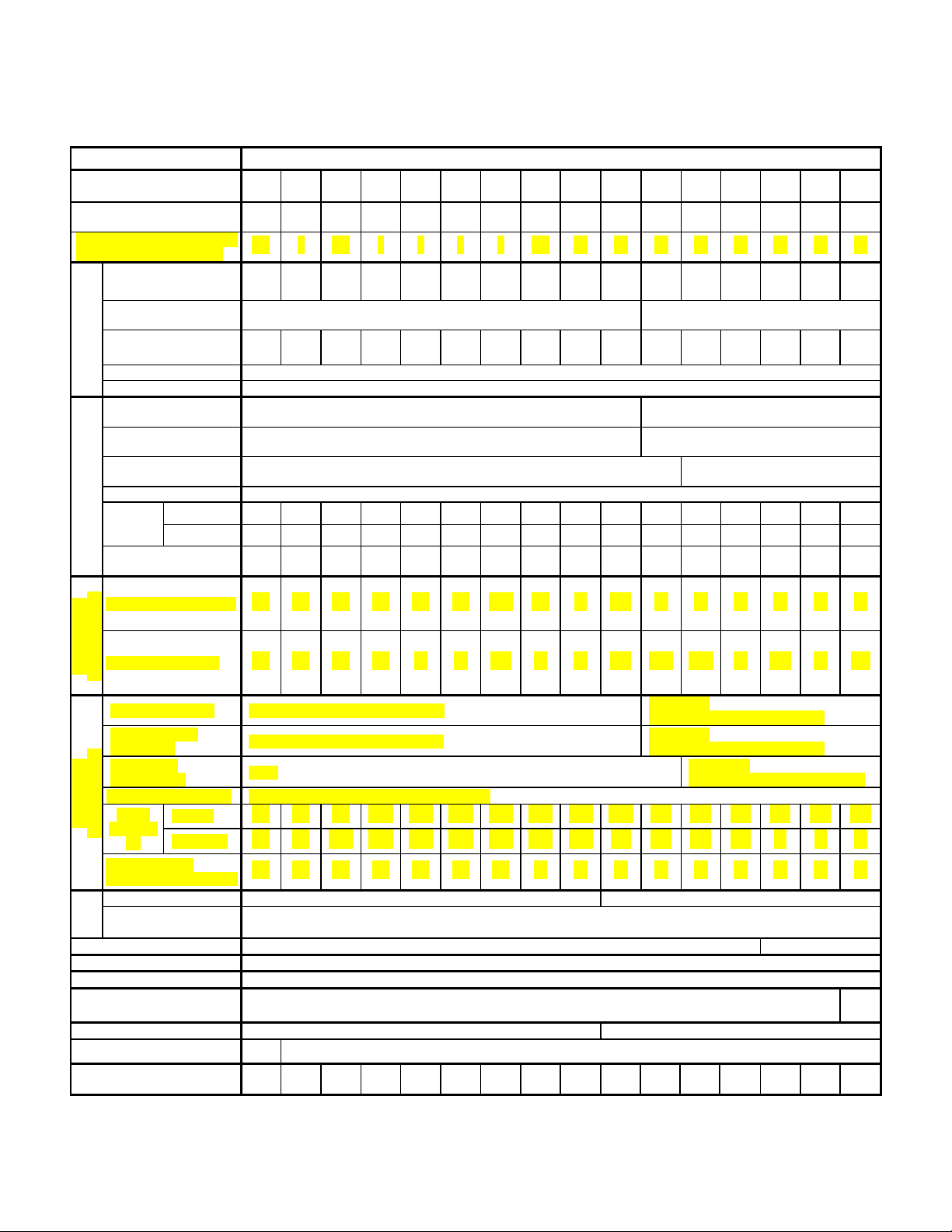
Standard specifications
Type
Nominal applied motor
for three phase input *1 [HP]
Nominal applied motor for
Output ratings for
Three-phase, 200V to 240V
(With AVR function )
Three-phase, 200V to 230V
(With AVR function )
Overload capability
120% of rated current for 1min
Rated frequency
50, 60Hz
Input ratings for
200 to 220V / 50Hz, 200 to 230V / 60Hz
Auxiliary control
power input
Single-phase,
200 to 220V / 50 Hz, 200 to 230V / 60Hz
Auxiliary fan
power input *5
Single-phase,
200 to 220V / 50Hz, 200 to 230V / 60Hz
Voltage/frequency variations
Voltage: +10 to -15% (Voltage unbalance: 2% or less *9), Frequency: +5 to -5%
Rated
[A]
Required power
supply capacity *7 [kVA]
Output ratings for
Input ratings for
200 to 220V / 50Hz, 200 to 230V / 60Hz
Voltage/frequency variations
Voltage: +10 to -10%, Frequency: +5 to -5%
Torque *8 [%]
20
10 to 15
DC injection
braking
DC reactor (DCR)
Option
Standard
KEYPAD
Multifunctional Keypad (TP-G1W)
UL508C
Enclosure(IEC60529)
IP20 / UL open type
IP00 / UL open type
7.1
(3.2)
7.3
(3.3)
7.3
(3.3)
7.5
(3.4)
13
(5.8)
13
(6.0)
15
(6.9)
21
(9.7)
21
(9.7)
25
(11.5)
51
(23)
73
(33)
75
(34)
90
(41)
90
(41)
265
(120)
1) 208V series (1 to 125HP)
Item Specifications
(FRN□□□F1S-2U)
001 002 003 005 007 010 015 020 025 030 040 050 060 075 100 125
1 2 3 5 7.5 10 15 20 25 30 40 50 60 75 100 125
1/2 1 1.5 2 3 5 5 7.5 10 10 15 20 25 25 30 40
single phase input *1[HP]
Rated capacity
*2a
(a)
1.6 2.7 3.8 6.0 9.0 11 16 21 27 31 41 51 60 76 98 123
[kVA]
Rated voltage *3 [V]
Rated current *4
4.6 7.5 10.6 16.7 25 31 47 60 75 88 114 143 169 211 273 343
[A]
three phase input
Main power supply Three-phase,200 to 240V, 50/60Hz
Single-phase,200 to 240V, 50/60Hz
None
current *6
three phase input
(a)
Rated capacity
with DCR
without DCR
*2a
3.1 5.8 8.7 14.5 20.6 27.5 41.3 55.1 68.8 82.6 109 134 160 199 270 333
5.1 9.1 12.9 21.5 30.8 40.8 59.4 76.6 94.0 110 144 179 215
1.2
[kVA]
0.8 1.6 2.3 3.3 3.9 6.1 7.5
a)
2.1
3.2 5.3 7.5 10 15 20 25 30 40 49 58 72 98 120
b)
8.6 11 13
Three-phase,
- - -
b)
16 21 27 27 34 41
Rated current
*4
[A] 2.4 4.6 6.6 9.3 11 17 21
single phase input
Main power supply SIngle-phase,200 to 240V, 50/60Hz
Auxiliary control
power input
(a)
Auxiliary fan
power input *5
Rated
current *6
single phase input
[A]
Required power
supply capacity
Braking
with DCR
without DCR
*7
Single-phase,200 to 240V, 50/60Hz
None
3.4 6.3 9.2 16.7 24.5 31.6 40.9 53.6 65.6 77.6 109 138 165 169 215 272
5.1 9.1 12.9 21.5 30.8 40.8 59.4 76.6 94.0 110 144 179 215 --- --- ---
0.8 1.4 2.0 3.5 5.1 6.6 8.6 12 14 17 23 29 35 36 45 57
[kVA]
Starting frequency: 0.0 to 60.0Hz, Braking time: 0.0 to 30.0s, Braking level: 0 to 60%
EMC Filter Option
Applicable safety standards UL508C, C22.2 No.14, EN50178:1997
Cooling method
Natural
cooling
Fan cooling
Mass [lbs(kg)]
b)
24 31 37
b)
46.2 59.4 75 76
Single-phase,
Single-phase,
200 to 220V / 50 Hz, 200 to 230V / 60Hz
Single-phase,
200 to 220V / 50Hz, 200 to 230V / 60Hz
b)
95 114
C22.2
No.14
1
Page 3

2) 460V series (1 to 75HP)
Type
Nominal applied motor
for three phase input *1 [HP]
Nominal applied motor
for single phase input *1[HP]
[A]
Three-phase,
Auxiliary control
Single-phase,
380 to 480V / 60Hz
Voltage/frequency variations
Voltage: +10 to -15% (Voltage unbalance: 2% or less *9), Frequency: +5 to -5%
Rated
[A]
Required power
Auxiliary control
Single-phase,
Single-phase,
Voltage/frequency variations
Voltage: +10 to -10%, Frequency: +5 to -5%
Torque *8 [%]
20
10 to 15
DC reactor (DCR)
Option
EMC Filter
Option
KEYPAD
Multifunctional Keypad (TP-G1W)
Cooling method
Natural cooling
Fan cooling
6.8
(3.1)
7.1
(3.2)
7.3
(3.3)
7.5
(3.4)
7.5
(3.4)
13
(6.0)
13
(6.0)
15
(6.9)
22
(9.9)
22
(9.9)
25
(11.5)
51
(23)
53
(24)
73
(33)
Item Specifications
(FRN□□□F1S-4U)
Rated capacity
Rated voltage*3 [V] Three-phase, 380V to 480V (With AVR function )
Rated current *4
Overload capability 120% of rated current for 1min
Output ratings for
three phase input
Rated frequency 50, 60Hz
Main power supply Three-phase, 380 to 480V, 50/60Hz
power input
Auxiliary fan
power input
Input ratings for
three phase input
current *6
supply capacity *7 [kVA]
(a)
Rated capacity
*2b
[kVA]
*5
with DCR
without DCR
*2b
001 002 003 005 007 010 015 020 025 030 040 050 060 075
1 2 3 5 7.5 10 15 20 25 30 40 50 60 75
1/4 1 1 2 3 3 7.5 7.5 10 10 15 20 20 30
(a)
1.9 2.9 4.3 7.1 9.9 13 18 23 29 35 47 57 67 83
2.5 3.7 5.5 9.0 12.5 16.5 23 30 37 44 59 72 85 105
Single-phase, 380 to 480V, 50/60Hz
None
1.3 2.5 3.8 6.2 8.9 11.8 17.7 23.7 29.6 35.5 46.8 57.0 68.4 85.7
2.5 4.8 6.9 10.8 14.5 19.1 27.7 36.0 43.6 50.9 64.0 78.5 93.7 118
1.1 2.0 3.1 5.0 7.1
[kVA]
0.9 1.6 2.1 2.9 4.6 6.2 9.5 10 12 15 18 23 27 34
380 to 440V / 50Hz, 380 to 480V / 60Hz
380 to 440V / 50Hz, 380 to 480V / 60Hz
a)
9.5
15 19 24 29 38 46 55 69
Single-phase,
380 to 440V / 50Hz
Rated current
Output ratings for
single phase input
Main power supply Single-phase, 380 to 480V, 50/60Hz
power input
(a)
Auxiliary fan
power input *5
Rated
Input ratings for
single phase input
current *6
[A]
Required power
supply capacity
DC injection
Braking
braking
Applicable safety standards UL508C, C22.2 No.14, EN50178:1997
Enclosure(IEC60529) IP20 / UL open type IP00 / UL open type
Mass [lbs(kg)]
*4
[A]
with DCR
without DCR
*7
[kVA]
1.2 2.1 2.7 3.7 5.8 7.9 12 13 16 19 23 30 35 43
Single-phase,
380 to 440V / 50Hz, 380 to 480V / 60Hz
Single-phase, 380 to 480V, 50/60Hz
None
1.5 2.9 4.1 6.2 9.5 12.9 20.1 23.5 28.8 34.9 43.9 57.6 69.3 85.2
2.5 4.8 6.9 10.8 14.5 19.1 27.7 36.0 43.6 50.9 64.0 78.5 93.7 115
0.7 1.4 1.9 2.9 4.4 6.0 9.3 11 14 17 21 27 32 40
Starting frequency: 0.0 to 60.0Hz, Braking time: 0.0 to 30.0s, Braking level: 0 to 60%
380 to 440V / 50Hz, 380 to 480V / 60Hz
380 to 440V / 50Hz
380 to 480V / 60Hz
2
Page 4

3) 460V series (100 to 900HP)
Type
Nominal applied motor
for three phase input *1 [HP]
Nominal applied motor
for single phase input *1 [HP]
Rated current *4
Main power supply
Three-phase, 380 to 440V / 50Hz, 380 to 480V / 60Hz
Auxiliary control
power input
Auxiliary fan
Required power
supply capacity
[kVA]
Main power supply
Single-phase, 380 to 440V / 50Hz, 380 to 480V / 60Hz
Auxiliary control
power input
Auxiliary fan
power input *5
Voltage/frequency variations
Voltage: +10 to -10%, Frequency: +5 to -5%
Torque *8 [%]
10 to 15
DC injection
Braking
DC reactor (DCR)
Standard (External)
KEYPAD
Multifunctional Keypad (TP-G1W)
Applicable safety standards
UL508C, C22.2 No.14, EN50178:1997
UL508C, C22.2 No.14
Enclosure(IEC60529)
IP00 / UL open type
Cooling method
Fan cooling
75
(34)
93
(42)
99
(45)
139
(63)
212
(96)
212
(96)
216
(98)
357
(162)
357
(162)
529
(240)
529
(240)
783
(355)
794
(360)
794
(360)
Item Specifications
(FRN□□□F1S-4U)
100 125 150 200 250 300 350 400 450 500 600 700 800 900
100 125 150 200 250 300 350 400 450 500 600 700 800 900
30 40 50 60 75 100 100 125 125 150 200 200 250 250
(a)
Rated capacity
*2b
110 133 161 191 240 286 330 380 414 517 589 669 764 828
[kVA]
Rated voltage *3 [V] Three-phase, 380V to 480V (With AVR function )
139 168 203 240 302 360 415 477 520 650 740 840 960
Overload capability 120% of rated current for 1min
Output ratings for
three phase input
Rated frequency 50, 60Hz
[A]
Single-phase, 380 to 440V / 50Hz, 380 to 480V / 60Hz
power input *5
Voltage/frequency variations
Rated
*6
current
Input ratings for
three phase input
[A]
(a)
Rated capacity
with DCR
without DCR
*7
*2b
Single-phase, 380 to 440V / 50Hz, 380 to 480V / 60Hz
Voltage: +10 to -15% (Voltage unbalance: 2% or less *9), Frequency: +5 to -5%
113 140 169 222 275 330 382 440 495 545 652 756 869 981
- - - - - - - - - - - - - -
91 112 135 177 220 263 305 351 395 435 520 603 693 782
[kVA]
40 50 60 73 78 107 129 136 160 195 228 263 309 327
1040
Rated current
Output ratings for
single phase input
*4
[A]
51 63 76 92 98 135 162 171 202 246 287 331 388 411
Single-phase, 380 to 440V / 50Hz, 380 to 480V / 60Hz
(a)
Rated
current *6
Input ratings for
single phase input
[A]
Required power
supply capacity *7[kVA]
Braking
with DCR
without DCR
Single-phase, 380 to 440V / 50Hz, 380 to 480V / 60Hz
102 125 151 180 231 271 311 363 392 482 560 636 714 782
--- --- --- --- --- --- --- --- --- --- --- --- --- ---
47 58 70 83 107 125 144 167 181 222 258 293 329 360
Starting frequency: 0.0 to 60.0Hz, Braking time: 0.0 to 30.0s, Braking level: 0 to 60%
EMC Filter Option
Mass [lbs(kg)]
3
Page 5

3(5.2.3))(IEC61800 67
[V] voltage average phase-Three
[V] voltage Min.[V] voltage Max.
unbalance Voltage −×
−
=
:
Notes
*1 Standard 4-pole motor
*2a Rated capacity is calculated by assuming the output rated voltage as 208V for three-phase & single-phase input.
*2b Rated capacity is calculated by assuming the output rated voltage as 460V for three-phase & single-phase input.
*3 Output voltage cannot exceed the power supply voltage.
*4 An excessively low setting of the carrier frequency may result in the higher motor temperature or tripping of the inverter
by its overcurrent limiter setting. Lower the continuous load or maximum load instead. (When setting the carrier
frequency (F26) to 1kHz, reduce the load to 80% of its rating.)
*5 Use [R1,T1] terminals for driving AC cooling fans of an inverter powered by the DC link bus, such as by a high power
factor PWM converter. (In ordinary operation, the terminals are not used.)
*6 Calculated under Fuji-specif ied conditions.
*7 Obtained when a DC reactor (DCR) is used.
*8 Average braking torque (Varies with the efficiency of the motor.)
*9
If this value is 2 to 3%, use an AC reactor (ACR).
(a) When utilized on a single phase application the drive’s output voltage may be lower than the nominal rated voltage
4
Page 6

Change
running
Change
running
0: Disable
2: Enable (FWD inhibited)
OFF
Acceleration/deceleration time 1(F07/F08)
ON
Acceleration/deceleration time 2(E10/E11)
The following functions have been added to FRENIC-Eco inverters that contain a ROM version
number of 2000 or high er.
The inverter’s ROM version can be found through the keypad utilizing the “Maintenance
Information” menu (menu # 5).
Additional Function Codes
Acceleration/deceleration time 2
Code Name Data Setting Range Increment Unit
E10 Acceleration Time 2
0.00 to 3600 Variable s Y Y 20.0
E11 Deceleration Time 2
Selection between ACC/DEC time 1(F07/F08) and ACC/DEC time 2(E10/E11) requires the
use of one of the drive’s programmable digital input te rm i na ls [X1], [X2], [X3], [X4] , [X5],
[FWD], or [REV]. Set the associated digital input terminal parameter E01, E02, E03, E04,
E05, E98, or E99 equal to “4 (1004): RT1” (a setting of 1004 assigns negative logic to the
input terminal). If no RT1 command is assigned one of the programmable digital input
terminals then ACC/DEC time 1(F07/F08) takes effect by default.
Input terminal command RT1 Acceleration/deceleration time
When the terminal command STOP is off, the motor decelerates to a stop in accordance
with the deceleration time for forced stop (H56). After the motor stops, the inverter
enters the alarm state with the alarm Er6 displayed.
Rotational Direction Limitation
when
Data
Copy
Default
Setting
Code Name Data Setting Range Increment Unit
H08
Rotational Direction
Limitation
H08 inhibits the motor form running in an unexpected rotational direction due to miss-operation of
run commands, miss-polarization of frequency commands, or other installation/wiring/user errors.
1: Enable (REV inhibited)
5
when
- - N Y 0
Data
Copy
Default
Setting
 Loading...