

Page 1

Designed for Fan and Pump Applications
Instruction Manual
Thank you for purchasing our FRENIC-Eco series of inverters.
• This product is designed to drive a three-phase induction motor. Read through this instruction manual and
be familiar with the handling procedure for correct use.
• Improper handling might result in incorrect operation, a short life, or even a failure of this product as well as
the motor.
• Deliver this manual to the end user of this product. Keep this manual in a safe place until this product is
discarded.
• For how to use an optional device, refer to the installation and instruction manuals for that optional device.
Fuji Electric FA Components & Systems Co., Ltd.
Fuji Electric Corp. of America INR-SI47-1225-E
Page 2

Copyright © 2007 Fuji Electric FA Components & Systems Co., Ltd.
All rights reserved.
No part of this publication may be reproduced or copied without prior written permission from Fuji Electric FA
Components & Systems Co., Ltd.
All products and company names mentioned in this manual are trademarks or registered trademarks of their
respective holders.
The information contained herein is subject to change without prior notice for improvement.
Page 3
Preface
Thank you for purchasing our FRENIC-Eco series of inverters.
This product is designed to drive a three-phase induction motor for fan and pump applications. Read through this
instruction manual and be familiar with proper handling and operation of this product.
Improper handling might result in incorrect operation, a short life, or even a failure of this product as well as the
motor.
Have this manual delivered to the end user of this product. Keep this manual in a safe place until this product is
discarded.
Listed below are the other materials related to the use of the FRENIC-Eco. Read them in conjunction with this
manual as necessary.
• FRENIC-Eco User's Manual
• RS-485 Communication User's Manual
• Catalog
• Relay Output Card "OPC-F1-RY" Instruction Manual
• Mounting Adapter for External Cooling "PB-F1" Installation Manual
• Panel-mount Adapter "MA-F1" Installation Manual
• FRENIC Loader Instruction Manual
The materials are subject to change without notice. Be sure to obtain the latest editions for use.
Safety precautions
Read this manual thoroughly before proceeding with installation, connections (wiring), operation, or maintenance
and inspection. Ensure you have sound knowledge of the device and familiarize yourself with all safety
information and precautions before proceeding to operate the inverter.
Safety precautions are classified into the following two categories in this manual.
Failure to heed the information indicated by this symbol may lead to
dangerous conditions, possibly resulting in death or serious bodily injuries.
Failure to heed the information indicated by this symbol may lead to
dangerous conditions, possibly resulting in minor or light bodily injuries
and/or substantial property damage.
Failure to heed the information contained under the CAUTION title can also result in serious consequences.
These safety precautions are of utmost importance and must be observed at all times.
i
Page 4
Application
• FRENIC-Eco is designed to drive a three-phase induction motor. Do not use it for single-phase motors
or for other purposes.
Fire or an accident could occur.
• FRENIC-Eco may not be used for a life-support system or other purposes directly related to the human
safety.
• Though FRENIC-Eco is manufactured under strict quality control, install safety devices for applications
where serious accidents or material losses are foreseen in relation to the failure of it.
An accident could occur.
Installation
• Install the inverter on a nonflammable material such as metal.
Otherwise fire could occur.
• Do not place flammable matter nearby.
Doing so could cause fire.
• Do not support the inverter by its terminal block cover during transportation.
Doing so could cause a drop of the inverter and injuries.
• Prevent lint, paper fibers, sawdust, dust, metallic chips, or other foreign materials from getting into the
inverter or from accumulating on the heat sink.
Otherwise, a fire or an accident might result.
• Do not install or operate an inverter that is damaged or lacking parts.
Doing so could cause fire, an accident or injuries.
• Do not get on a shipping box.
• Do not stack shipping boxes higher than the indicated information printed on those boxes.
Doing so could cause injuries.
ii
Page 5

Wiring
• When wiring the inverter to the power source, insert a recommended molded case circuit breaker
(MCCB) or residual-current-operated protective device (RCD)/a ground fault circuit
interrupter(GFCI)(with overcurrent protection) in the path of power lines. Use the devices within the
recommended current range.
• Use wires in the specified size.
Otherwise, fire could occur.
• Do not use one multicore cable in order to connect several inverters with motors.
• Do not connect a surge suppressor to the inverter's output (secondary) circuit.
Doing so could cause fire.
• Ground the inverter in compliance with the national or local electric code.
Otherwise, electric shock could occur.
• Qualified electricians should carry out wiring.
• Be sure to perform wiring after turning the power OFF.
Otherwise, electric shock could occur.
• Be sure to perform wiring after installing the inverter body.
Otherwise, electric shock or injuries could occur.
• Ensure that the number of input phases and the rated voltage of the product match the number of
phases and the voltage of the AC power supply to which the product is to be connected.
Otherwise fire or an accident could occur.
• Do not connect the power source wires to output terminals (U, V, and W).
Doing so could cause fire or an accident.
• Generally, control signal wires are not enforced- insulated. If they accidentally touch any of live parts in
the main circuit, their insulation coat may break for any reasons. In such a case, an extremely high
voltage may be applied to the signal lines. Make a complete remedy to protect the signal line from
contacting any hot high voltage lines.
Otherwise, an accident or electric shock could occur.
• Wire the three-phase motor to terminals U, V, and W of the inverter, aligning phases each other.
Otherwise injuries could occur.
• The inverter, motor and wiring generate electric noise. Take care of malfunction of the nearby sensors
and devices. To prevent the motor from malfunctioning, implement noise control measures.
Otherwise an accident could occur.
iii
Page 6

Operation
• Be sure to install the terminal block cover and the front cover before turning the power ON. Do not
remove the covers while power is applied.
Otherwise electric shock could occur.
• Do not operate switches with wet hands.
Doing so could cause electric shock.
• If the retry function has been selected, the inverter may automatically restart and drive the motor
depending on the cause of tripping.
(Design the machinery or equipment so that human safety is ensured after restarting.)
• If the stall prevention function (current limiter), automatic deceleration, and overload prevention control
have been selected, the inverter may operate at an acceleration/deceleration time or frequency
different from the commanded ones. Design the machine so that safety is ensured even in such cases.
Otherwise an accident could occur.
• The
Switching the run command source from keypad (local) to external equipment (remote) by turning ON
• If an alarm reset is made with the Run command signal turned ON, a sudden start will occur. Ensure that
Otherwise an accident could occur.
• If you enable the "Restart mode after momentary power failure" (Function code F14 = 3, 4, or 5), then
(Design the machinery or equipment so that human safety is ensured after restarting.)
• If you set the function codes wrongly or without completely understanding this instruction manual and
An accident or injuries could occur.
• Do not touch the inverter terminals while the power is applied to the inverter even if the inverter stops.
Doing so could cause electric shock.
key on the keypad is effective only when the keypad operation is enabled with function code
F02 (= 0, 2 or 3). When the keypad operation is disabled, prepare an emergency stop switch separately
for safe operations.
the "Enable communications link" command (LE) or "Switch run command 2/1" command (FR2/FR1),
disables the
function code H96 (= 1 or 3).
the Run command signal is turned OFF in advance.
the inverter automatically restarts running the motor when the power is recovered.
the FRENIC-Eco User's Manual, the motor may rotate with a torque or at a speed not permitted for the
machine.
key. To enable the key for an emergency stop, select the STOP key priority with
iv
Page 7
• Do not turn the main circuit power (circuit breaker) ON or OFF in order to start or stop inverter operation.
Doing so could cause failure.
• Do not touch the heat sink because they become very hot.
Doing so could cause burns.
• Setting the inverter to high speeds is easy. Before changing the frequency (speed) setting, check the
specifications of the motor and machinery.
• The brake function of the inverter does not provide mechanical holding means.
Injuries could occur.
Setting control switches
• Before setting up any internal control switches, turn OFF the power and wait more than five minutes for
models of 30HP for 208V, 40HP for 460V or below, or ten minutes for models of 40HP for 208V, 50HP
for 460V or above. Make sure that the LED monitor and charging lamp (on models of 40HP for 208V,
50HP for 460V or above) are turned OFF. Further, make sure, using a multimeter or a similar
instrument, that the DC link bus voltage between the terminals P (+) and N (-) has dropped below the
safe voltage (+25 VDC).
Otherwise electric shock could occur.
Maintenance and inspection, and parts replacement
• Turn the power OFF and wait for at least five minutes for models of 30HP for 208V, 40HP for 460V or
below, or ten minutes for models of 40HP for 208V, 50HP for 460V or above, before starting inspection.
Further, check that the LED monitor and charging lamp (on models of 40HP for 208V, 50HP for 460V or
above) are unlit and that the DC link bus voltage between the P (+) and N (-) terminals is lower than 25
VDC.
Otherwise, electric shock could occur.
• Maintenance, inspection, and parts replacement should be made only by qualified persons.
• Take off the watch, rings and other metallic objects before starting work.
• Use insulated tools.
Otherwise, electric shock or injuries could occur.
Disposal
• Treat the inverter as an industrial waste when disposing of it.
Otherwise injuries could occur.
Others
• Never attempt to modify the inverter.
Doing so could cause electric shock or injuries.
GENERAL PRECAUTIONS
Drawings in this manual may be illustrated without covers or safety shields for explanation of detail parts.
Restore the covers and shields in the original state and observe the description in the manual before
starting operation.
v
Page 8

Conformity with Low Voltage Directive in the EU
If installed according to the guidelines given below, inverters marked with CE can be considered to be compliant
with the Low Voltage Directive 73/23/EEC.
1. Be sure to earth the grounding terminal zG. Use an earth wire sized more than that of the power wires
used in the power dispatch system. Do not use a residual-current-operated protective device (RCD)* or a
ground fault circuit interrupter(GFCI)* as a sole mechanism of electric shock protection.
*With overcurrent protection.
2. Use an MCCB, RCD/GFCI or MC in conformity with EN or IEC standards.
3. When an RCD/GFCI is used for protection of electric shock caused by a direct or indirect contact to the
live parts, insert a type B RCD/GFCI in input lines (primary) of the inverter for the 3-phase 208 V or 460 V
power source.
4. Use inverters in an environment that does not exceed pollution degree 2. If inverters are to be used in an
environment with pollution degree 3 or 4, place them in an enclosure of IP54 or above.
5. To protect human body from an electric shock caused by a contact to live parts, install inverters, AC
reactor and input /output filter in the enclosure of IP2X. In the case where human body easily contacts to
live parts, a top panel of the enclosure should be IP4X or higher.
6. Do not directly connect a copper wire to the grounding terminal. Use a crimp terminal with tin or equivalent
plating to connect the earth wire.
7. When using inverters at an altitude of more than 6600ft(2000 m), note that the basic insulation applies to
the insulation degree of the control circuitry. At an altitude of more than 9800ft(3000 m), inverters cannot
be used.
vi
Page 9
Conformity with Low Voltage Directive in the EU (continued)
8. Use the wires listed in EN60204-1.
Inverter type
motor (HP)
Nominal applied
Power supply voltage
1 FRN001F1S-2U 15
2 FRN002F1S-2U
3 FRN003F1S-2U
5 FRN005F1S-2U 20 30
7 FRN007F1S-2U 40 75 6.0 10 6.0
10 FRN010F1S-2U 50 100 10 16 10
15 FRN015F1S-2U 75 125 16 25
20 FRN020F1S-2U 150 25 35 25
25 FRN025F1S-2U
30 FRN030F1S-2U 150 200 50 70
40 FRN040F1S-2U 175 250 16x2 35x2
Three-phase 208 V
50 FRN050F1S-2U 200 300 50x2
60 FRN060F1S-2U 250 350
75 FRN075F1S-2U 50x2 70x2
100 FRN100F1S-2U
125 FRN125F1S-2U 500
1 FRN001F1S-4U 5
2 FRN002F1S-4U
3 FRN003F1S-4U 15
5 FRN005F1S-4U
7 FRN007F1S-4U 15 30
10 FRN010F1S-4U 20 40
15 FRN015F1S-4U 30 50 4.0 6.0
20 FRN020F1S-4U 60 10
25 FRN025F1S-4U
30 FRN030F1S-4U 50 100 10
40 FRN040F1S-4U 75 16 25 16
50 FRN050F1S-4U
60 FRN060F1S-4U
75 FRN075F1S-4U 125 200 35 25x2 16x2 50
100 FRN100F1S-4U 175 70 25x2 25x2
125 FRN125F1S-4U 200 95 95
150 FRN150F1S-4U 250 50x2
Three-phase 460 V
200 FRN200F1S-4U 300 70x2 70x2 70x2
250 FRN250F1S-4U 150 185 240
300 FRN300F1S-4U 185 240 120x2
350 FRN350F1S-4U
400 FRN400F1S-4U 150x2
450 FRN450F1S-4U
500 FRN500F1S-4U 800
600 FRN600F1S-4U 240x2 185x3
700 FRN700F1S-4U
800 FRN800F1S-4U 240x3 185x4
900 FRN900F1S-4U
1
*
The frame size and model of the MCCB or RCD/GFCI (with overcurrent protection) will vary, depending on the
power transformer capacity. Refer to the related technical documentation for details.
2
*
The recommended wire size for main circuits is for the 70°C(158°F) 600V PVC wires used at an ambient
temperature of 40°C(104
MCCB or
RCD/GFCI
Rated current
W/
DCR
10
100
350
5
10
40
100
500
600
1000
1200
°F).
(A)
Main power
1
*
input *2
[L1/R, L2/S, L3/T]
Inverter’s
grounding [zG]
W/o
W/
DCR
DCR
20
2.5
175 35 50
95
-
95x2 95x2 95x2
240
10
2.5
20
6.0
75
125
25
150
240
-
185x2
185x3 240x3
185x4
Recommended wire size (mm2)
2
[U, V, W]
[P1, P(+)]
W/o
DCR
2.5
4.0
70x2
-
2.5
4.0
16 10
35
50
150x2 150x2
-
185x2 185x2
240x2 240x2
240x4
DC reactor
Inverter outputs *
2.5 2.5
6.0
16
16 25
35
35
50 70
25x2 25x2
95 95
50x2
50x2
240 120x2
2.5 2.5
4.0 4.0
6.0 6.0
10
16
25
35
35
50x2
120
240x3
240x4
Control circuit
Europe type
terminal block
0.25
to
0.75
0.25
to
0.75
2.5
2.5
Aux. fan power
supply [R0, T0]
supply [R1, T1]
Aux. control power
-
2.5
-
2.5
vii
Page 10
Conformity with UL standards and CSA standards (cUL-listed for Canada)
UL/cUL-listed inverters are subject to the regulations set forth by the UL standards and CSA standards
(cUL-listed for Canada) by installation within precautions listed below.
1. Solid state motor overload protection (motor protection by electronic thermal overload relay) is provided in
each model.
Adjust function codes F10 to F12 to decide the protection level.
2. Suitable for use on a circuit capable of delivering not more than 100,000 rms three-phase symmetrical
amperes, 240 Volts maximum for 208V class input 30HP or less, 230 Volts maximum for 208V class input
40HP or above or 480 Volts maximum for 460V class input.
3. Use 60°C/75°C Cu wire only.
4. Use Class 1 wire only.
5. Field wiring connections must be made by a UL Listed and CSA Certified closed-loop terminal connector
sized for the wire gauge involved. Connector must be fixed using the crimp tool specified by the connector
manufacturer.
6. All circuits with terminals L1/R, L2/S, L3/T, R0, T0, R1, T1 must have a common disconnect and be
connected to the same pole of the disconnect if the terminals are connected to the power supply.
viii
Page 11
(
)
)
Conformity with UL standards and CSA standards (cUL-listed for Canada) (continued)
7. Install UL-listed fuses or circuit breaker between the power supply and the inverter, referring to the table
below.
Inverter type
Power supply voltage
FRN001F1S-2U 10
FRN002F1S-2U 15
FRN003F1S-2U
FRN005F1S-2U
FRN007F1S-2U
FRN010F1S-2U
FRN015F1S-2U
FRN020F1S-2U
FRN025F1S-2U
FRN030F1S-2U 175 175
FRN040F1S-2U
Three-phase 208 V
FRN050F1S-2U 3/0 (85.0) 225 225
FRN060F1S-2U 4/0 (107.2)
FRN075F1S-2U 300(152
FRN100F1S-2U
FRN125F1S-2U
FRN001F1S-4U 6
FRN002F1S-4U 10
FRN003F1S-4U 15
FRN005F1S-4U 20 20
FRN007F1S-4U
FRN010F1S-4U
FRN015F1S-4U
FRN020F1S-4U 70 50
FRN025F1S-4U
FRN030F1S-4U
FRN040F1S-4U
FRN050F1S-4U 2 (33.6) 125 125
FRN060F1S-4U 1 (42.4) - 150 150
FRN075F1S-4U 1/0 (53.5)
FRN100F1S-4U
FRN125F1S-4U 4/0 (107.2) 200 200
FRN150F1S-4U 250 (127) 225 225
Three-phase 460 V
FRN200F1S-4U
FRN250F1S-4U 500 (253) 400 400
FRN300F1S-4U 4/0x2 (107.2) 450 450
FRN350F1S-4U 300x2 (152) 500 500
FRN400F1S-4U 350x2 (177) 600 600
FRN450F1S-4U 400x2 (203)
FRN500F1S-4U 300x3 (152)
FRN600F1S-4U 350x3 (177)
FRN700F1S-4U 300x4 (152)
FRN800F1S-4U 350x4 (177) 1200 1200
FRN900F1S-4U
1
Select the rated current of a fuse or a circuit breaker which is suitable to the connecting wire size.
*
Required torque
Main
terminal
15.9
(1.8)
33.6
(3.8)
51.3
(5.8)
119.4
(13.5)
238.9
(27)
424.7
(48)
15.9
(1.8)
33.6
(3.8)
51.3
(5.8)
119.4
(13.5)
238.9
(27)
424.7
(48)
Ib-in (N·m)
Aux.
Control
Power
Supply
R0, T0
10.6
(1.2)
10.6
(1.2)
Control
circuit
Europe
type
terminal
block
4.4
(0.5)
4.4
(0.5)
Wire size
Aux.
14
(2.1)
14
(2.1)
2
)
Aux. Fan
Power
Supply
R1, T1
-
14
(2.1)
14
(2.1)
Control
circuit
Europe
type
terminal
block
20
(0.5)
20
(0.5)
AWG (mm
14
Control
Power
Supply
R0, T0
Main
terminal
(2.1)
12 (3.3)
8 (8.4)
4 (21.2)
3 (26.7)
2 (33.6)
1/0 (53.5)
2/0x2 (67.4) 350 350
4/0x2 (107.2)
14 (2.1)
12 (3.3)
10 (5.3)
8 (8.4)
6 (13.3)
4 (21.2)
3x2 (26.7)
2/0x2 (67.4) 300 300
400x4 (203)
Class J fuse size (A)
Circuit breaker trip size
15
20 20
35 30
60 50
70 70
100 100
125 125
150 150
200 200
300 300
400 400
15
30
30
40
50 40
80 70
80
100
100
175 175
700 700
1000 1000
1600 1600
A
ix
Page 12

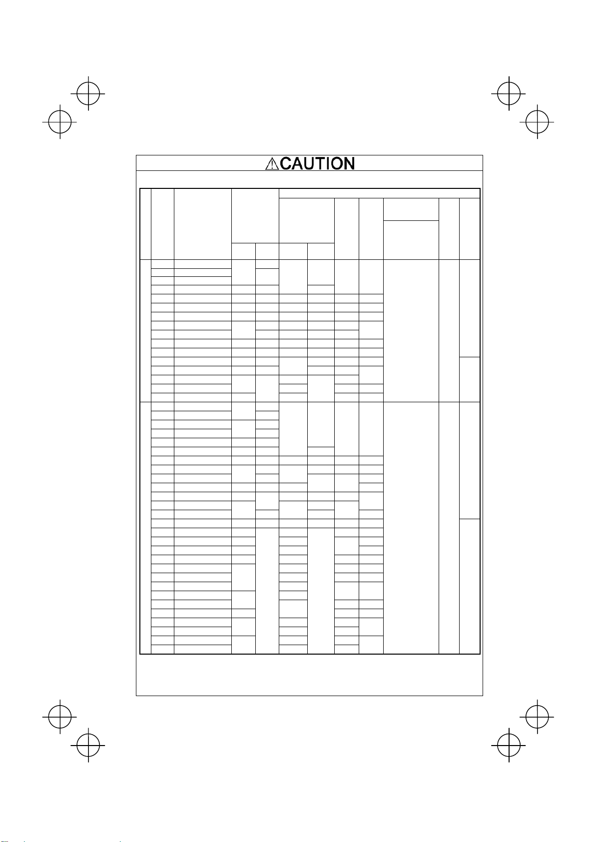
Precautions for use
In running
generalpurpose
motors
In running
special
motors
Environmental
conditions
Driving a 460V
general-purpose
motor
Torque
characteristics
and temperature
rise
Vibration
Noise
Explosion-proof
motors
Submersible
motors and
pumps
Brake motors
Geared motors
Synchronous
motors
Single-phase
motors
Installation
location
When driving a 460V general-purpose motor with an inverter using
extremely long wires, damage to the insulation of the motor may occur.
Use an output circuit filter (OFL) if necessary after checking with the motor
manufacturer. Fuji motors do not require the use of output circuit filters
because of their reinforced insulation.
When the inverter is used to run a general-purpose motor, the temperature
of the motor becomes higher than when it is operated using a commercial
power supply. In the low-speed range, the cooling effect will be weakened,
so decrease the output torque of the motor.
When an inverter-driven motor is mounted to a machine, resonance may
be caused by the natural frequencies of the machine system.
Note that operation of a 2-pole motor at 60 Hz or higher may cause
abnormal vibration.
* The use of a rubber coupling or vibration dampening rubber is
recommended.
* Use the inverter's jump frequency control feature to skip the resonance
frequency zone(s).
When an inverter is used with a general-purpose motor, the motor noise
level is higher than that with a commercial power supply. To reduce noise,
raise carrier frequency of the inverter. Operation at 60 Hz or higher can
also result in higher noise level.
When driving an explosion-proof motor with an inverter, use a combination
of a motor and an inverter that has been approved in advance.
These motors have a larger rated current than general-purpose motors.
Select an inverter whose rated output current is greater than that of the
motor.
These motors differ from general-purpose motors in thermal
characteristics. Set a low value in the thermal time constant of the motor
when setting the electronic thermal function.
For motors equipped with parallel-connected brakes, their braking power
must be supplied from the primary circuit. If the brake power is connected
to the inverter's output circuit by mistake, the brake will not work.
Do not use inverters for driving motors equipped with series-connected
brakes.
If the power transmission mechanism uses an oil-lubricated gearbox or
speed changer/reducer, then continuous motor operation at low speed
may cause poor lubrication. Avoid such operation.
It is necessary to take special measures suitable for this motor type.
Contact your Fuji Electric representative for details.
Single-phase motors are not suitable for inverter-driven variable speed
operation. Use three-phase motors.
Use the inverter within the ambient temperature range from -10 to +50°C
(14 to 122
°F).
The heat sink of the inverter may become hot under certain operating
conditions, so install the inverter on nonflammable material such as metal.
Ensure that the installation location meets the environmental conditions
specified in Chapter 2, Section 2.1 "Operating Environment."
x
Page 13

Combination with
peripheral
devices
Wiring
Installing an
MCCB or
RCD/GFCI
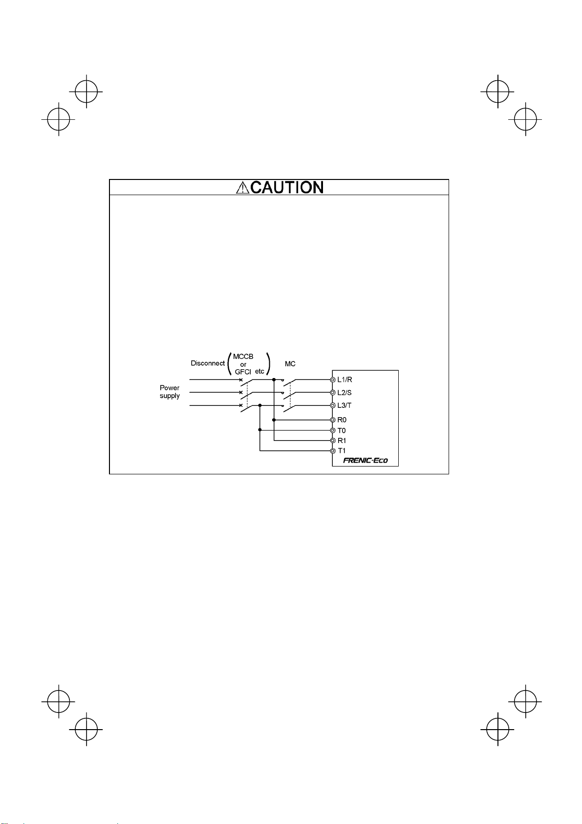
Installing an MC
in the secondary
circuit
Installing an MC
in the primary
circuit
Install a recommended molded case circuit breaker (MCCB) or
residual-current-operated protective device (RCD)/a ground fault circuit
interrupter (GFCI) (with overcurrent protection) in the primary circuit of the
inverter to protect the wiring. Ensure that the circuit breaker rated current is
equivalent to or lower than the recommended rated current.
If a magnetic contactor (MC) is mounted in the inverter's output
(secondary) circuit for switching the motor to commercial power or for any
other purpose, ensure that both the inverter and the motor are completely
stopped before you turn the MC ON or OFF.
Remove the magnet contactor (MC) already installed and built-in surge
suppressor from the inverter's output (secondary) circuit before installing
the MC to switch the motor power.
Do not turn the magnetic contactor (MC) in the primary circuit ON or OFF
more than once an hour as an inverter failure may result.
If frequent starts or stops are required during motor operation, use
(FWD)/(REV) signals or the RUN/STOP key.
The electronic thermal function of the inverter can protect the motor. The
operation level and the motor type (general-purpose motor, inverter motor)
should be set. For high-speed motors or water-cooled motors, set a small
Protecting the
motor
Use of
power-factor
correcting
capacitor
Use of surge
suppressor
Reducing noise
value for the thermal time constant and protect the motor.
If you connect the motor thermal relay to the motor with a long wire, a
high-frequency current may flow into the wiring stray capacitance. This
may cause the relay to trip at a current lower than the set value for the
thermal relay. If this happens, lower the carrier frequency or use the output
circuit filter (OFL).
Do not mount power-factor correcting capacitors in the inverter’s primary
circuit. (Use the DC reactor to improve the inverter power factor.) Do not
use power-factor correcting capacitors in the inverter’s output (secondary)
circuit. An overcurrent trip will occur, disabling motor operation.
Do not connect a surge suppressor to the inverter's output (secondary)
circuit.
Use of a filter and shielded wires is typically recommended to satisfy EMC
Directives.
If an overvoltage trip occurs while the inverter is stopped or operated under
Measures against
surge currents
a light load, it is assumed that the surge current is generated by open/close
of the power-factor correcting capacitor in the power system.
* Connect a DC reactor to the inverter.
Megger test
When checking the insulation resistance of the inverter, use a 500 V
megger and follow the instructions contained in Chapter 7, Section 7.5
"Insulation Test."
Control circuit
wiring length
Wiring length
between inverter
and motor
When using remote control, limit the wiring length between the inverter and
operator box to 67ft (20m) or less and use twisted pair or shielded wire.
If long wiring is used between the inverter and the motor, the inverter will
overheat or trip as a result of overcurrent (high-frequency current flowing
into the stray capacitance) in the wires connected to the phases. Ensure
that the wiring is shorter than 164ft (50m). If this length must be exceeded,
lower the carrier frequency or mount an output circuit filter (OFL).
Wiring size
Wiring type
Select wires with a sufficient capacity by referring to the current value or
recommended wire size.
When several inverters drive motors, do not use one multicore cable in
order to connect several inverters with motors.
Grounding Securely ground the inverter using the grounding terminal.
xi
Page 14

Selecting
inverter
capacity
Transportation and
storage
Select an inverter according to the applicable motor ratings listed in the
Driving
general-purpose
motor
Driving special
motors
When transporting or storing inverters, follow the procedures and select locations that meet the
environmental conditions listed in Chapter 1, Section 1.3 "Transportation" and Section 1.4
standard specifications table for the inverter.
When high starting torque is required or quick acceleration or deceleration
is required, select an inverter with a capacity one size greater than the
standard.
Select an inverter that meets the following condition:
Inverter rated current > Motor rated current
"Storage Environment."
xii
Page 15

How this manual is organized
This manual is made up of chapters 1 through 10.
Chapter 1 BEFORE USING THE INVERTER
This chapter describes acceptance inspection and precautions for transportation and storage of the inverter.
Chapter 2 MOUNTING AND WIRING OF THE INVERTER
This chapter provides operating environment, precautions for installing the inverter, wiring instructions for the
motor and inverter.
Chapter 3 OPERATION USING THE KEYPAD
This chapter describes inverter operation using the keypad. The inverter features three operation modes
(Running, Programming and Alarm modes) which enable you to run and stop the motor, monitor running status,
set function code data, display running information required for maintenance, and display alarm data.
Chapter 4 OPERATION
This chapter describes preparation to be made before running the motor for a test and practical operation.
Chapter 5 FUNCTION CODES
This chapter provides a list of the function codes. Function codes to be used often and irregular ones are
described individually.
Chapter 6 TROUBLESHOOTING
This chapter describes troubleshooting procedures to be followed when the inverter malfunctions or detects an
alarm condition. In this chapter, first check whether any alarm code is displayed or not, and then proceed to the
troubleshooting items.
Chapter 7 MAINTENANCE AND INSPECTION
This chapter describes inspection, measurement and insulation test which are required for safe inverter operation.
It also provides information about periodical replacement parts and guarantee of the product.
Chapter 8 SPECIFICATIONS
This chapter lists specifications including output ratings, control system, external dimensions and protective
functions.
Chapter 9 LIST OF PERIPHERAL EQUIPMENT AND OPTIONS
This chapter describes main peripheral equipment and options which can be connected to the FRENIC-Eco
series of inverters.
Chapter 10 CONFORMITY WITH STANDARDS
This chapter describes standards with which the FRENIC-Eco series of inverters comply.
Icons
The following icons are used throughout this manual.
This icon indicates information which, if not heeded, can result in the inverter not operating to full
efficiency, as well as information concerning incorrect operations and settings which can result in
accidents.
This icon indicates information that can prove handy when performing certain settings or operations.
This icon indicates a reference to more detailed information.
xiii
Page 16

Table of Contents
Preface ........................................................................i
Safety precautions..............................................................i
Precautions for use ...........................................................x
How this manual is organized ............................................ xiii
Chapter 1 BEFORE USING THE INVERTER .................1-1
1.1 Acceptance Inspection........................................... 1-1
1.2 External View and Terminal Blocks........................ 1-2
1.3 Transportation........................................................ 1-4
1.4 Storage Environment............................................. 1-4
1.4.1 Temporary storage ........................................ 1-4
1.4.2 Long-term storage......................................... 1-4
Chapter 2 MOUNTING AND WIRING OF
Chapter 3 OPERATION USING THE MULTI-FUNCTION
Chapter 4 RUNNING THE MOTOR ................................ 4-1
THE INVERTER............................................. 2-1
2.1 Operating Environment.......................................... 2-1
2.2 Installing the Inverter .............................................2-1
2.3 Wiring .................................................................... 2-6
2.3.1 Removing and mounting the terminal
block (TB) cover and the front cover............. 2-6
2.3.2 Removing and mounting the cable guide
plate (for models of 1 to 25HP for 208V and 1 to
30HP for 460V) ........................................... 2-10
2.3.3 Terminal arrangement diagram and screw
specifications .............................................. 2-11
2.3.4 Recommended wire sizes........................... 2-14
2.3.5 Wiring precautions ...................................... 2-15
2.3.6 Wiring for main circuit terminals and
grounding terminals..................................... 2-15
2.3.7 Wiring for control circuit terminals...............2-24
2.3.8 Setting up slide switches and handling
control circuit terminal symbol plate ............ 2-34
2.4 Mounting and Connecting a Keypad.................... 2-35
2.4.1 Mounting style and parts needed
for connection ............................................. 2-35
2.4.2 Mounting/installing steps............................. 2-36
2.5 Cautions Relating to Harmonic Component,
Noise, and Leakage Current................................ 2-38
KEYPAD......................................................... 3-1
3.1 Key, LED, and LCD Monitors on the Keypad......... 3-1
3.2 Overview of Operation Modes ............................... 3-4
3.3 Running Mode ....................................................... 3-5
3.3.1 Running/stopping the motor .......................... 3-5
3.3.2 Setting up the frequency and PID process
commands .................................................... 3-8
3.3.3 LED monitor (Monitoring the running status) ...3-12
3.4 Programming Mode............................................. 3-13
3.4.1 Setting function codes – "1. Data Setting"... 3-14
3.4.2 Setting up function codes quickly using Quick
setup – "0. QUICK SET" ............................. 3-17
3.4.3 Checking changed function codes
–"2. DATA CHECK"..................................... 3-17
3.4.4 Monitoring the running status
–"3. OPR MNTR" ........................................3-18
3.4.5 Checking I/O signal status
– "4. I/O CHECK" ........................................ 3-20
3.4.6 Reading maintenance information
– "5. MAINTENANC"................................... 3-23
3.4.7 Reading alarm information – "6. ALM INF".. 3-26
3.4.8 Viewing cause of alarm
– "7. ALM CAUSE"...................................... 3-29
3.4.9 Data copying – "8. DATA COPY"................. 3-31
3.4.10 Measuring load factor – "9. LOAD FCTR"... 3-38
3.4.11 Changing function codes covered by Quick setup
– "10. USER SET"....................................... 3-41
3.4.12 Performing communication debugging
– "11. COMM DEBUG"................................ 3-42
3.5 Alarm Mode ......................................................... 3-43
3.6 Other Precautions................................................ 3-45
3.6.1 Function code setting for F02 (Run and
operation).................................................... 3-45
3.6.2 Remote/local operation ...............................3-45
3.6.3 Tuning motor parameters............................ 3-46
4.1 Running the Motor for a Test.................................. 4-1
4.1.1 Inspection and preparation prior to
powering on .................................................. 4-1
4.1.2 Turning ON power and checking................... 4-1
4.1.3 Preparation before running the motor
for a test--Setting function code data ............4-1
4.1.4 Test run ......................................................... 4-4
4.2 Operation............................................................... 4-4
Chapter 5 FUNCTION CODES .......................................5-1
5.1 Function Code Tables............................................ 5-1
5.2 Overview of Function Codes................................ 5-23
Chapter 6 TROUBLESHOOTING ................................... 6-1
6.1 Before Proceeding with Troubleshooting ...............6-1
6.2 If No Alarm Code Appears on the LED Monitor......6-2
6.2.1 Motor is running abnormally.......................... 6-2
6.2.2 Problems with inverter settings ..................... 6-7
6.3 If an Alarm Code Appears on the LED Monitor...... 6-8
6.4 If an Abnormal Pattern Appears on the LED
Monitor while No Alarm Code is Displayed.......... 6-19
Chapter 7 MAINTENANCE AND INSPECTION.............. 7-1
7.1 Daily Inspection ..................................................... 7-1
7.2 Periodic Inspection ................................................ 7-1
7.3 List of Periodical Replacement Parts..................... 7-3
7.3.1 Judgment on service life ...............................7-3
7.4 Measurement of Electrical Amounts
in Main Circuit........................................................ 7-5
7.5 Insulation Test........................................................ 7-6
7.6 Inquiries about Product and Guarantee................. 7-7
Chapter 8 SPECIFICATIONS..........................................8-1
8.1 Standard Models .................................................... 8-1
8.1.1 Three-phase 208 V ....................................... 8-1
8.1.2 Three-phase 460 V ....................................... 8-2
8.2 Specifications of Keypad Related .......................... 8-4
8.2.1 General specifications of keypad ..................8-4
8.2.2 Communications specifications of keypad ....8-4
8.2.3 Data transmission specifications................... 8-5
8.3 Common Specifications .........................................8-6
8.4 Terminal Specifications .......................................... 8-8
8.4.1 Terminal functions ......................................... 8-8
8.4.2 Running the inverter with keypad.................. 8-9
8.4.3 Running the inverter by terminal
commands .................................................. 8-10
8.5 External Dimensions............................................ 8-12
8.5.1 Standard models......................................... 8-12
8.5.2 DC reactor................................................... 8-15
8.5.3 Multi-function Keypad.................................. 8-16
8.6 Protective Functions ............................................ 8-17
Chapter 9 LIST OF PERIPHERAL EQUIPMENT AND
Chapter 10 CONFORMITY WITH STANDARDS ............ 10-1
OPTIONS ....................................................... 9-1
10.1 Conformity with UL Standards and Canadian
Standards (cUL-listed for Canada)....................... 10-1
10.1.1 General ....................................................... 10-1
10.1.2 Considerations when using FRENIC-Eco
as a product certified by UL or cUL............. 10-1
10.2 Conformity with EU Directives .............................10-1
10.3 Conformity with Low Voltage Directive................. 10-1
10.3.1 General ....................................................... 10-1
10.3.2 Considerations when using FRENIC-Eco
as a product in conformity with
Low Voltage Directive..................................10-1
10.4 Harmonic Component Regulation in the EU........ 10-2
10.4.1 General ....................................................... 10-2
10.4.2 Conformity with the harmonics regulation ... 10-2
10.5 Conformity with the EMC Directive in the EU.......10-3
10.5.1 General ....................................................... 10-3
10.5.2 EMC-compliant filter (Option)...................... 10-3
10.5.3 Recommended installation of
EMC-compliant filter.................................... 10-5
10.5.4 EMC-compliant environment and class....... 10-6
xiv
Page 17
Chapter 1 BEFORE USING THE INVERTER
1.1 Acceptance Inspection
Unpack the package and check the following:
(1) An inverter and accessories below are contained in the package.
• Cooling fan fixing screws (for inverters of 7.5 to 30HP for 208V and 10 to 40HP for 460V)
• Keypad fixing screws (for inverters of 1 to 30HP for 208V and 1 to 40HP for 460V)
• Bush rubbers for cable guide plate (for inverters of 1 to 25HP for 208V and 1 to 30HP for 460V)
• Instruction manual (this manual)
(2) The inverter has not been damaged during transportation—there should be no dents or parts missing.
(3) The inverter is the model you ordered. You can check the model name and specifications on the main
nameplate. (Main and sub nameplates are attached to the inverter and are located as shown on the following
page.) For the inverter whose capacity is 40HP for 208V, 50HP for 460V or above, its mass is printed on the
nameplate.
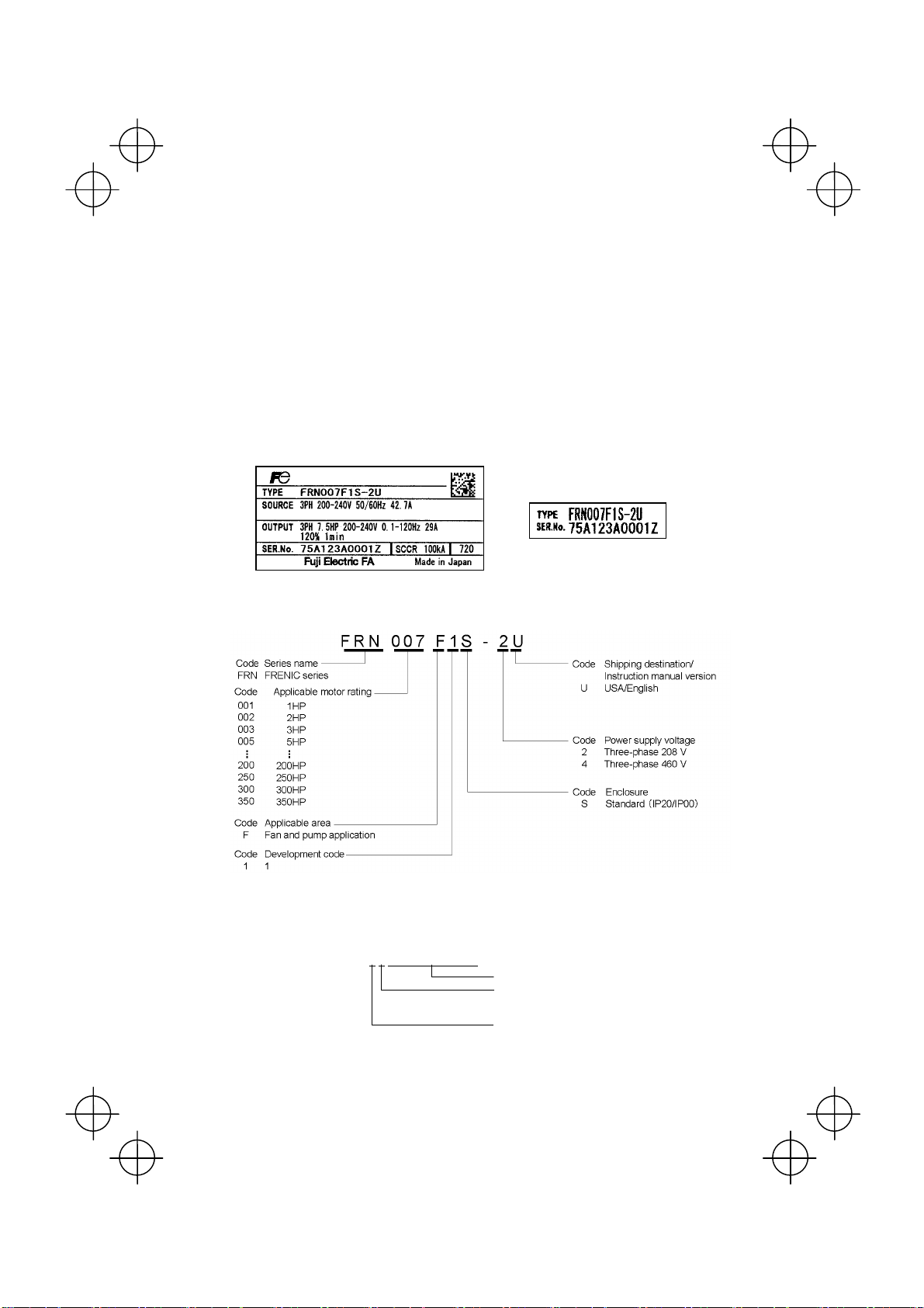
TYPE: Type of inverter
(a) Main Nameplate (b) Sub Nameplate
Figure 1.1 Nameplates
SOURCE: Number of input phases (three-phase: 3PH), input voltage, input frequency, input current
OUTPUT: Number of output phases, rated output capacity, rated output voltage, output frequency range, rated
output current, overload capacity
MASS: Mass of the inverter in pound
SER. No.: Product number
5 A 1 2 3 A 0 0 0 1 Z
7
Serial number of production lot
Production month
1 to 9: January to September
X, Y, or Z: October, November, or December
Production year: Last digit of year
If you suspect the product is not working properly or if you have any questions about your product, contact your
Fuji Electric representative.
1-1
Page 18
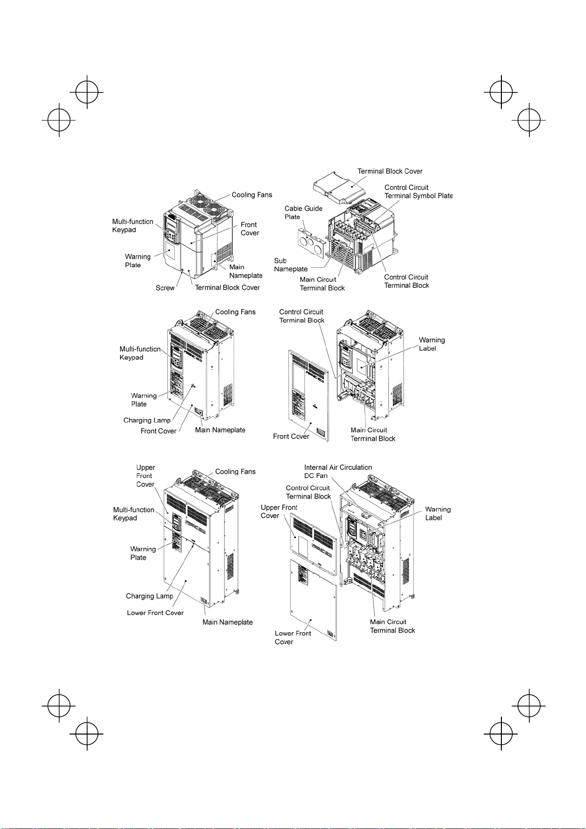
1.2 External View and Terminal Blocks
(1) Outside and inside views
(a) FRN015F1S-2U
(b) FRN040F1S-2U
Figure 1.2 Outside and Inside Views of Inverters
(c) FRN350F1S-4U
1-2
Page 19
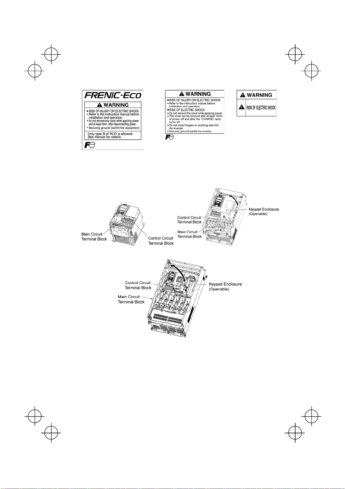
(2) Warning plates and label
Warning Plate
(a) FRN015F1S-2U
(3) Terminal block location
(a) FRN015F1S-2U
Warning Plate Warning Label
(b) FRN040F1S-2U
Figure 1.3 Warning Plates and Label
(b) FRN040F1S-2U
Figure 1.4 Terminal Blocks and Keypad Enclosure Location
(c) FRN350F1S-4U
1-3
Page 20

1.3 Transportation
• When carrying an inverter, always support its bottom at the front and rear sides with both hands. Do not hold
covers or individual parts only. You may drop the inverter or break it.
• When hoisting an inverter with hoisting holes, hook or rope the 4 holes evenly.
1.4 Storage Environment
1.4.1 Temporary storage
Store the inverter in an environment that satisfies the requirements listed in Table 1.1.
Table 1.1 Environmental Requirements for Storage and Transportation
Item Requirements
Storage temperature *1-25 to +70°C(-13° to 158°F)
Relative humidity 5 to 95% *2
Atmosphere The inverter must not be exposed to dust, direct sunlight, corrosive or flammable gases, oil
1
*
Assuming a comparatively short storage period (e.g., during transportation or the like).
2
Even if the humidity is within the specified requirements, avoid such places where the inverter will be subjected to
*
sudden changes in temperature that will cause condensation to form.
mist, vapor, water drops or vibration. The atmosphere must contain only a low level of salt.
(0.01 mg/cm
86 to 106 kPa (in storage) Atmospheric pressure
70 to 106 kPa (during transportation)
2
or less per year)
Precautions for temporary storage
(1) Do not leave the inverter directly on the floor.
(2) If the environment does not satisfy the specified requirements, wrap the inverter in an airtight vinyl sheet or
the like for storage.
(3) If the inverter is to be stored in an environment with a high level of humidity, put a drying agent (such as silica
gel) in the airtight package described in item (2).
1.4.2 Long-term storage
The long-term storage methods for the inverter vary largely according to the environment of the storage site.
General storage methods are described below.
(1) The storage site must satisfy the requirements specified for temporary storage.
However, for storage exceeding three months, the ambient temperature should be within the range from -10
to +30 °C(14 to 56°F). This is to prevent the electrolytic capacitors in the inverter from deteriorating.
(2) The inverter must be stored in a package that is airtight to protect it from moisture. Include a drying agent
inside the package to maintain the relative humidity inside the package to within 70%.
(3) If the inverter has been installed in the equipment or control board at a construction site where it may be
subjected to humidity, dust or dirt, then remove the inverter and store it in a suitable environment specified in
Table 1.1.
Precautions for storage over 1 year
If the inverter will not be powered on for a long time, the property of the electrolytic capacitors may deteriorate.
Power the inverters on once a year and keep them on for 30 to 60 minutes. Do not connect the inverters to motors
or run the motor.
A location where the inverter is not subject to abrupt
changes in temperature that would result in the formation of
condensation or ice.
1-4
Page 21
f
Chapter 2 MOUNTING AND WIRING OF THE INVERTER
2.1 Operating Environment
Install the inverter in an environment that satisfies the requirements listed in Table 2.1.
Table 2.1 Environmental Requirements
Item Specifications
Site location Indoors
Ambient
-10 to +50°C(14 to 122°F) (Note 1)
temperature
Relative
humidity
Atmosphere The inverter must not be exposed to dust, direct
5 to 95% (No condensation)
sunlight, corrosive gases, flammable gas, oil mist,
vapor or water drops.
Pollution degree 2 (IEC60664-1)
The atmosphere can contain a small amount of salt.
(0.01 mg/cm
The inverter must not be subjected to sudden
changes in temperature that will cause
condensation to form.
2
or less per year)
(Note 2)
Altitude 3300ft(1000m) max. (Note 3)
Atmospheric
pressure
Vibration
86 to 106 kPa
For inverters of 100 HP or below
3 mm (Max. amplitude) 2 to less than 9 Hz
9.8 m/s2 9 to less than 20 Hz
2 m/s2 20 to less than 55 Hz
1 m/s2 55 to less than 200 Hz
For inverters of 125 HP or above
3 m/s2 (Max. amplitude) 2 to less than 9 Hz
2 m/s2 9 to less than 55 Hz
2
55 to less than 200 Hz
1 m/s
2.2 Installing the Inverter
(1) Mounting base
The temperature of the heat sink will rise up to approx. 90°C during
operation of the inverter, so the inverter should be mounted on a
base made of material that can withstand temperatures of this level.
Table 2.2 Output Current Derating Factor in
Relation to Altitude
Altitude
3300ft(1000m) or lower 1.00
3300ft(1000m) to 4900ft(1500m) 0.97
4900ft(1500m) to 6600ft(2000m) 0.95
6600ft(2000m) to 8200ft(2500m) 0.91
8200ft(2500m) to 9800ft(3000m) 0.88
(Note 1) When inverters are mounted
side-by-side without any gap between them
(5HP for 208V, 7.5HP for 460HP or below),
the ambient temperature should be within
the range from -10 to +40°C(14 to 104°F).
(Note 2) Do not install the inverter in an
environment where it may be exposed to
cotton waste or moist dust or dirt which will
clog the heat sink in the inverter. If the
inverter is to be used in such an
environment, install it in the enclosure o
your system or other dustproof containers.
(Note 3) If you use the inverter in an
altitude above 3300ft(1000m), you should
apply an output current derating factor as
listed in Table 2.2.
Output
current
derating
factor
Install the inverter on a base constructed from metal or other
non-flammable material.
A fire may result with other material.
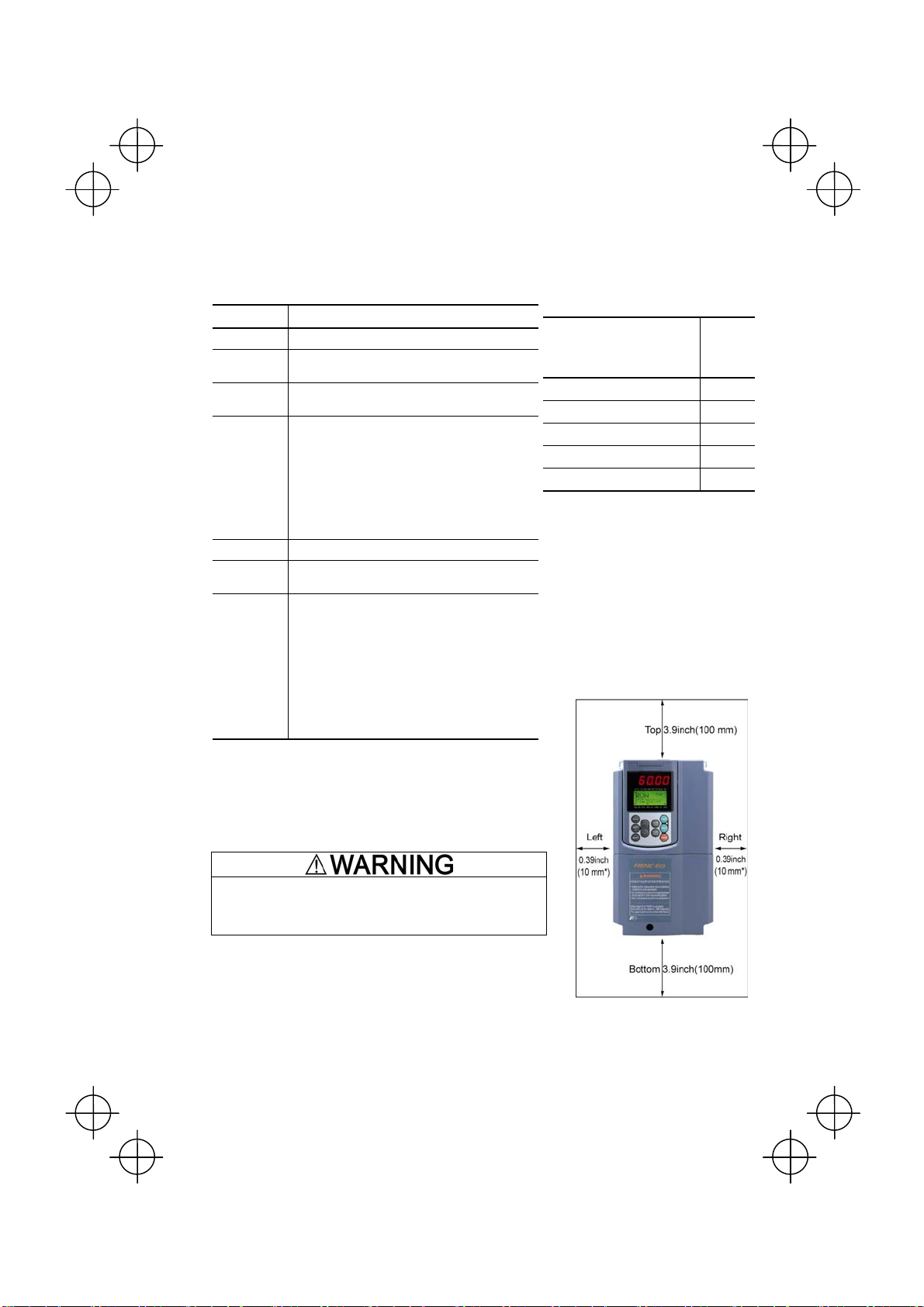
(2) Clearances
Ensure that the minimum clearances indicated in Figure 2.1 are
maintained at all times. When installing the inverter in the enclosure
of your system, take extra care with ventilation inside the enclosure
as the temperature around the inverter will tend to increase. Do not
install the inverter in a small enclosure with poor ventilation.
2-1
* 2.0inch(50mm) for models
of 460 V series 125HP or
above
Figure 2.1 Mounting Direction and
Required Clearances
Page 22
r
When mounting two or more inverters
Horizontal layout is recommended when two or more inverters are
to be installed in the same unit or enclosure. If it is necessary to
mount the inverters vertically, install a partition plate or the like
between the inverters so that any heat radiating from an inverter will
not affect the one/s above. As long as the ambient temperature is
40°C(104°F)or lower, inverters can be mounted side-by-side without
any gap between them (only for inverters with a capacity of 5HP fo
208V, 7.5HP for 460V or below).
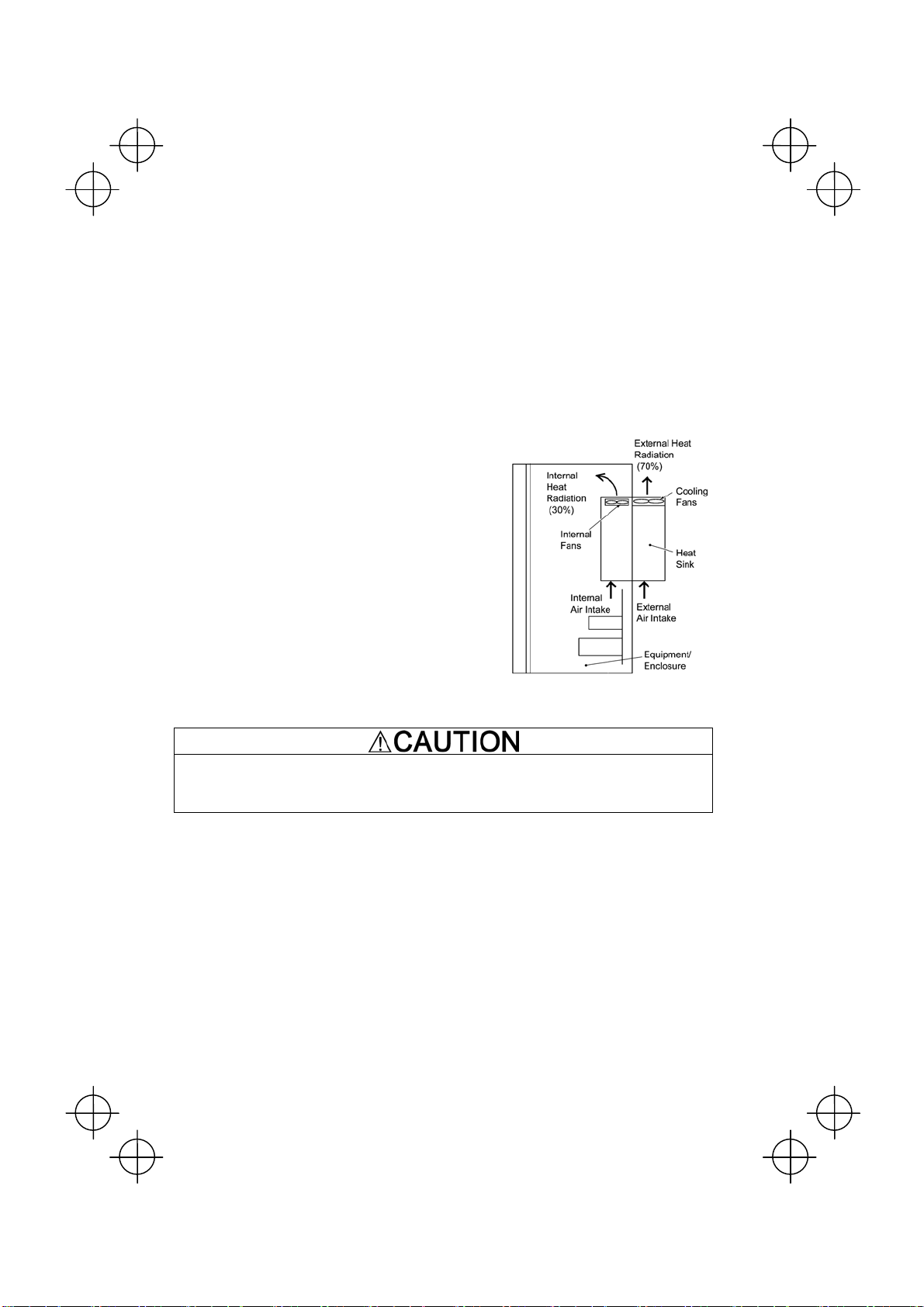
When employing external cooling
At the shipment time, the inverter is set up for mount inside your
equipment or enclosure so that cooling is done all internally.
To improve cooling efficiently, you can take the heat sink out of
the equipment or the enclosure (as shown on the right) so that
cooling is done both internally and externally (this is called
"external cooling").
In external cooling, the heat sink, which dissipates about 70% of
the total heat (total loss) generated into air, is situated outside the
equipment or the enclosure. As a result, much less heat is
radiated inside the equipment or the enclosure.
To take advantage of external cooling, you need to use the
external cooling attachment option for inverters with a capacity of
30HP for 208V, 40HP for 460V or below, or simply re-position the
mounting bases for the cooling unit for inverters with a capacity of
40HP for 208V, 50HP for 460V or above.
In an environment with high humidity or a lot of fibrous dust,
however, do not use external cooling in an environment with high
humidity or a lot of fibrous dust, which tends to clog the heat sink.
For details, refer to the Mounting Adapter for External
Cooling "PB-F1" Installation Manual and FRENIC-Eco
User’s Manual.
Figure 2.2 External Cooling
Prevent lint, paper fibers, sawdust, dust, metallic chips, or other foreign materials from getting into the
inverter or from accumulating on the heat sink.
This may result in a fire or accident.
2-2
Page 23

To utilize external cooling for inverters with a capacity of 40HP for 208V, 50HP for 460V or above, change the
position of the top and bottom mounting bases from the edge to the center of the inverter as illustrated in Figure
2.3.
Screws differ in size, length and count for each inverter. Be sure to refer to the table below.
Table 2.3 Screw Count and Tightening Torque
Power
supply
voltage
3-phase
208 V
3-phase
460 V
Inverter type
FRN040F1S-2U to
FRN100F1S-2U
FRN050F1S-4U to
FRN150F1S-4U
FRN200F1S-4U to
FRN350F1S-4U
For models shown in Figure A
Base fixing screw
(Count)
M6 × 20
(3 pcs each for upper
and lower sides)
M6 × 20
(3 pcs each for upper
and lower sides)
M6 × 20
(2 pcs each for upper
and lower sides)
M5 × 16
(4 pcs each for upper
and lower sides)
Case fixing screw
(Count)
M6 × 12
(3 pcs for upper side)
M6 × 12
(3 pcs for upper side)
M6 × 20
(2 pcs each for upper
and lower sides)
M5 × 12
(4 pcs each for upper
and lower sides)
Tightening torque
(N
•m)
5.8
5.8
5.8
3.5
Refer to:
Figure A
Figure B
1) Remove all of the base fixing screws from the top and bottom of the inverter. Also remove the case fixing
screws from the top. (The case fixing screws are not necessary in external cooling. Store them for future
use. On the bottom are no case fixing screws.)
2) Secure the top mounting base to the center of the inverter with the base fixing screws, using case fixing
screw holes.
3) Secure the bottom mounting base to the center of the inverter with the base fixing screws.
For models shown in Figure B
1) Remove all of the base fixing screws from the top and bottom of the inverter. Also remove the case fixing
screws.
2) Secure the top mounting base to the center of the inverter with the base fixing screws, using case fixing
screw holes. Set the removed case fixing screws to the screw holes where the top mounting bases were
secured.
3) In the same way, secure the bottom mounting base to the center of the inverter.
2-3
Page 24
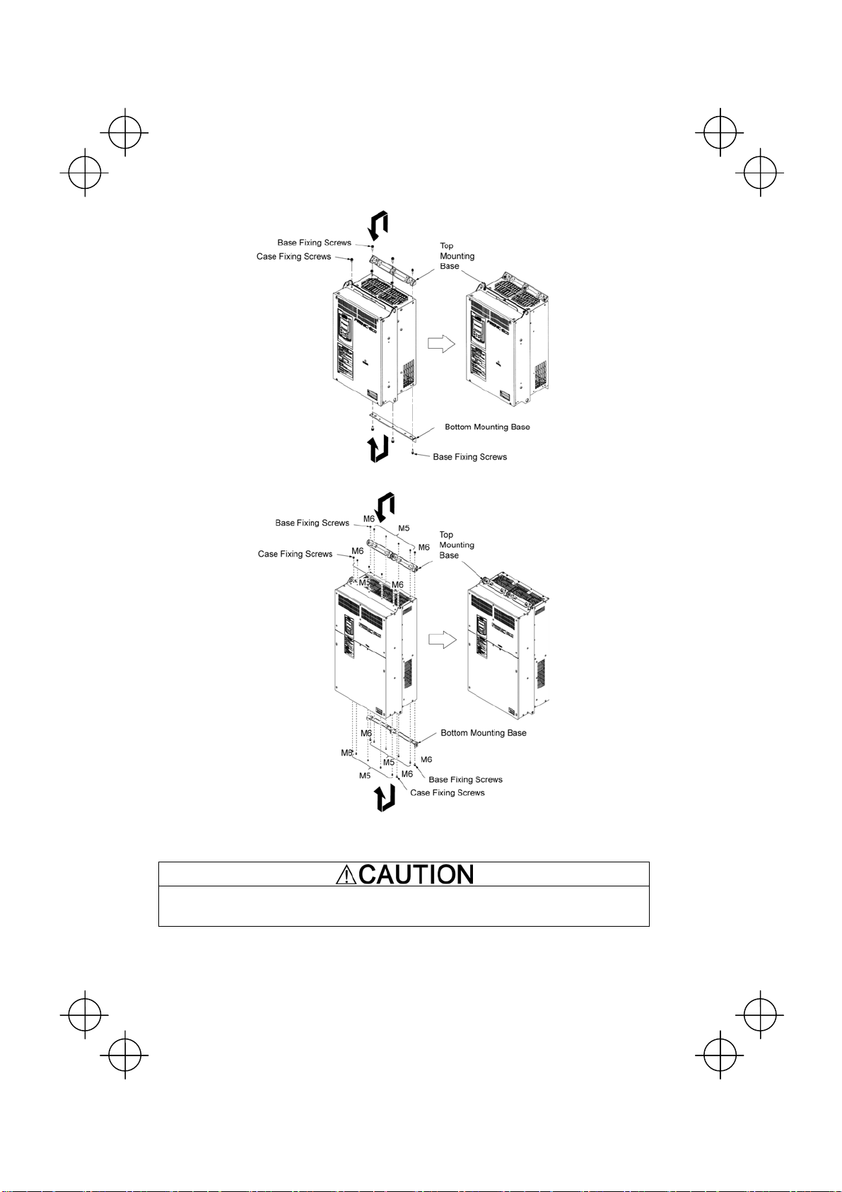
Figure A
Figure B
Figure 2.3 Relocating the Top and Bottom Mounting Bases
When moving the top and bottom mounting bases, use only the specified screws.
A fire or an accident may be caused.
2-4
Page 25
t
(3) Mounting direction
Mount the inverter vertically to the mounting surface and fix it securely with four screws or bolts so that the logo
"FRENIC-Eco" can be seen from the front.
Do not mount the inverter upside down or horizontally. Doing so will reduce the heat dissipation
efficiency of the inverter and cause the overheat protection function to operate, so the inverter will no
run.
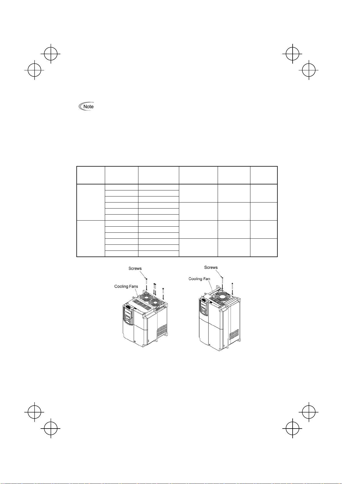
(4) Solving abnormal vibration after installation
If any vibration in the surroundings reaches the inverter and causes abnormal vibration to the cooling fan(s) or
the keypad, fix them firmly using the fixing screws provided as accessories.
Fixing the cooling fan(s)
Table 2.4 Fixing Screws
Power
supply
voltage
Threephase
208 V
Threephase
460 V
Nominal
applied motor
(HP)
7 FRN007F1S-2U
10 FRN010F1S-2U
15 FRN015F1S-2U
20 FRN020F1S-2U
25 FRN025F1S-2U
30 FRN030F1S-2U
10 FRN010F1S-4U
15 FRN015F1S-4U
20 FRN020F1S-4U
25 FRN025F1S-4U
30 FRN030F1S-4U
40 FRN040F1S-4U
Inverter type
Screw size
(accessory)
M4x35 (4 pcs) 0.8 Figure A
M4x50 (2 pcs) 0.5 Figure B
M4x35 (4 pcs) 0.8 Figure A
M4x50 (2 pcs) 0.5 Figure B
Tightening
torque
(N·m)
Refer to:
Figure A Figure B
Figure 2.4 Fixing the Cooling Fan(s)
2-5
Page 26
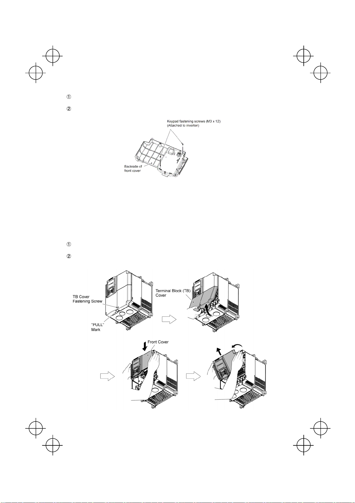
Fixing the keypad (for models of 30HP for 208V, 40HP for 460V or below)
Remove the terminal block (TB) cover and the front cover. (For the procedure, refer to 2.3.1 “Removing and
mounting the terminal block (TB) cover and the front cover.”)
To fix the front cover and keypad, hold the front cover and the keypad together and tighten the two attached
screws (provided as accessories) from the back of the keypad.
Figure 2.5 Fixing Multi-function Keypad
2.3 Wiring
Follow the procedure below. (In the following description, the inverter has already been installed.)
2.3.1 Removing and mounting the terminal block (TB) cover and the front cover
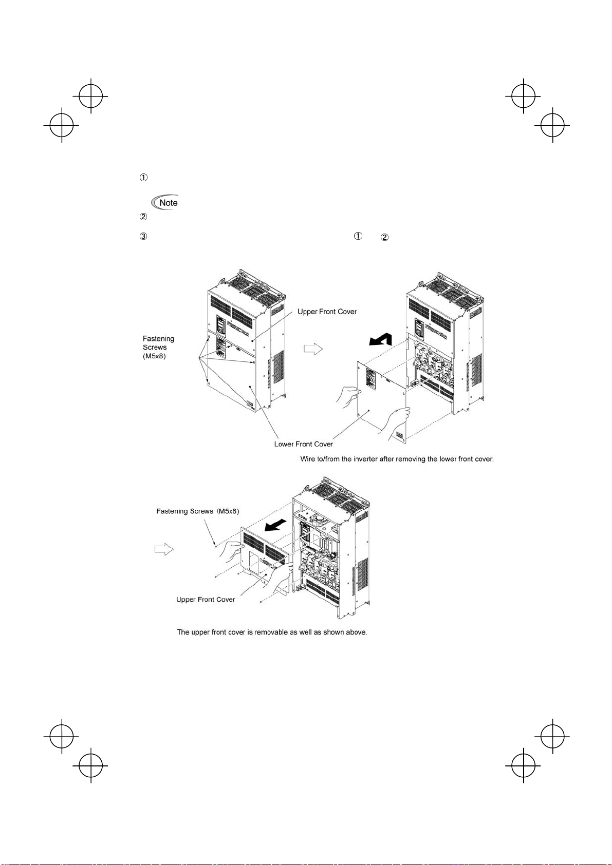
(1) For inverters with a capacity of 30HP for 208V, 40HP for 460V or below
Removing the covers
To remove the terminal block (TB) cover, first loosen the TB cover fastening screw on it, and put your finger
in the dimple of the terminal block (TB) cover (labeled “PULL”), and then pull it up toward you.
To remove the front cover, hold it with both hands, slide it downward to unlatch. Tilt the front cover toward
you, and pull it upward.
Tightening torque: 6.2lb-in(0.7 N·m)
Figure 2.6 Removing the Covers (FRN015F1S-2U)*
2-6
Page 27
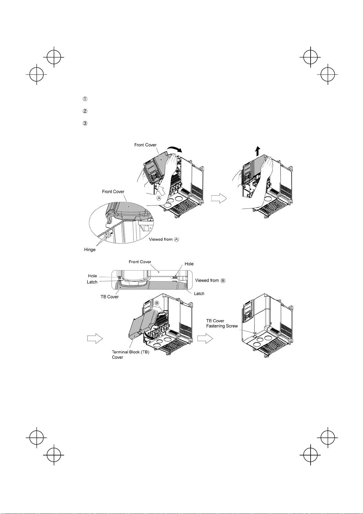
Mounting the covers
Put the front cover to the inverter case while fitting the edge of the front cover between the both hinges
provided on the inverter case. Slide it upward until the front cover latches.
Fit the latches on the terminal block (TB) cover in the holes provided to the front cover and push it towards
the inverter case.
Tighten the TB cover fastening screw on the terminal block (TB) cover (Tightening torque: 15.9lb-in(1.8
N·m)).
Figure 2.7 Mounting the Covers (FRN015F1S-2U)*
2-7
Page 28
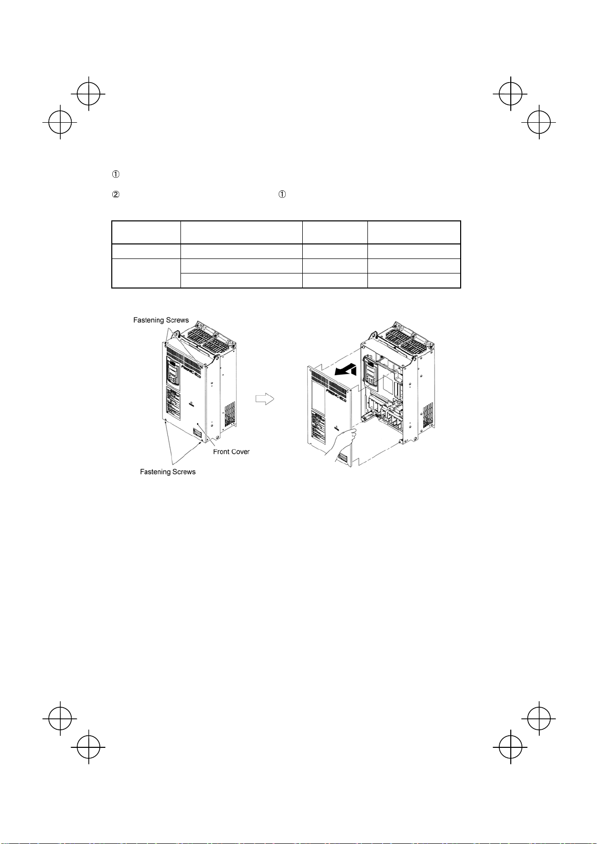
(2) For inverters with a capacity of 40HP for 208V, 50HP for 460V to 125HP for 208V, 200HP for 460V
Removing and mounting the covers
To remove the front cover, loosen the four fastening screws on it, hold it with both hands, and slide it
upward. (Refer to Figure 2.8.)
Put the front cover back in reverse order of the . Make sure to properly match the position of the screw
holes on both of the front cover and inverter case.
Table 2.5 Screw count and tightening torque
Power supply voltage Inverter type Front cover screw
Three-phase 208 V FRN040F1S-2U
Three-phase 460 V
FRN050F1S-4U
FRN200F1S-4U M4x8 (4 pcs) 31.0(3.5)
FRN100F1S-2U M4x8 (4 pcs) 15.9(1.8)
to
FRN150F1S-4U M4x8 (4 pcs) 15.9(1.8)
to
Tightening torque
lb-in(N·m)
Figure 2.8 Removing the Front Cover (FRN040F1S-2U)*
2-8
Page 29
(3) For inverters with a capacity of 250HP to 300HP
Removing and mounting the covers
To remove the lower front cover, loosen the five fastening screws on it, and hold it with both hands, and
then slide it upward.
You can do wiring works just removing the lower front cover.
To remove the upper front cover, loosen the five screws on it while supporting it with a hand. Pull and
remove it with both hands. (Refer to Figure 2.9.)
Put back the upper and lower front covers in reverse order of and
position of the screw holes on the upper and lower front covers and inverter case.
Make sure to properly match the
.
Tightening torque: 31.0lb-in(3.5 N·m)
Figure 2.9 Removing the Front Covers (FRN350F1S-4U)*
2-9
Page 30
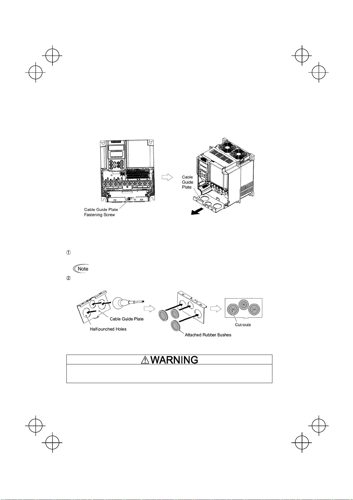
2.3.2 Removing and mounting the cable guide plate (for models of 1 to 25HP for 208V and 1 to 30HP
for 460V)
For inverters of 25HP for 208V, 30HP for 460V or below use the cable guide plate to secure IP20 protective
structure. Follow the steps to work on it.
Removing the cable guide plate
Before to proceed, remove the terminal block cover in advance.
Remove the cable guide plate fastening screw, and pull the cable guide plate.
Figure 2.10 Removing the Cable Guide Plate (FRN015F1S-2U)*
Opening half-punched holes and mounting rubber bushes
Tap the three half-punched holes of the cable guide plate by using a screwdriver grip end or the like and
punch them out.
Be careful not to injure yourself by sharp cutting edges of parts.
Set the three attached rubber bushes in the punched holes. Make cut-outs on the rubber bushes before
wiring.
Figure 2.11 Punching out the Holes and Mounting the Rubber Bushes
Be sure to use the rubber bushes. If not, a sharp cutting edge of the cable guide plate hole may damage the cable
sheath. This may induce a short-circuit fault or ground fault.
A fire or an accident may be caused.
Mounting the cable guide plate
Mount the cable guide plate following the steps illustrated in Figure 2.10 in reverse. (Tightening torque:
15.9lb-in(1.8 N
•
m))
2-10
Page 31

2.3.3 Terminal arrangement diagram and screw specifications
The table below shows the main circuit screw sizes, tightening torque and terminal arrangements. Note that the
terminal arrangements differ according to the inverter types. Two terminals designed for grounding shown as the
symbol,
(a secondary circuit).
in Figures A to J make no distinction between a power supply source (a primary circuit) and a motor
(1) Arrangement of the main circuit terminals
Table 2.6 Main Circuit Terminal Properties
Power supply
voltage
Threephase
208 V
Threephase
460 V
Terminal R0, T0 (Common to all types): Screw size M3.5, Tightening torque 10.6lb-in(1.2 (N·m))
Terminal R1, T1: Screw size M3.5, Tightening torque 8lb-in(0.9 (N·m)) (for the models of 208 V series 50HP or above, for
460 V series 60HP or above
Nominal applied
motor(HP)
1 FRN001F1S-2U
2 FRN002F1S-2U
3 FRN003F1S-2U
5 FRN005F1S-2U
7 FRN007F1S-2U
10 FRN010F1S-2U
15 FRN015F1S-2U
20 FRN020F1S-2U
25 FRN025F1S-2U
30 FRN030F1S-2U
40 FRN040F1S-2U
50 FRN050F1S-2U
60 FRN060F1S-2U
75 FRN075F1S-2U
100 FRN100F1S-2U
125 FRN125F1S-2U
1 FRN001F1S-4U
2 FRN002F1S-4U
3 FRN003F1S-4U
5 FRN005F1S-4U
7 FRN007F1S-4U
10 FRN010F1S-4U
15 FRN015F1S-4U
20 FRN020F1S-4U
25 FRN025F1S-4U
30 FRN030F1S-4U
40 FRN040F1S-4U
50 FRN050F1S-4U
60 FRN060F1S-4U
75 FRN075F1S-4U
100 FRN100F1S-4U
125 FRN125F1S-4U
150 FRN150F1S-4U
200 FRN200F1S-4U
250 FRN250F1S-4U
300 FRN300F1S-4U
350 FRN350F1S-4U
400 FRN400F1S-4U
450 FRN450F1S-4U
500 FRN500F1S-4U
600 FRN600F1S-4U
700 FRN700F1S-4U
800 FRN800F1S-4U
900 FRN900F1S-4U
Inverter type
Terminal
screw size
M10 27
M12 48 M10 27 Figure J
M10 27
M12 48
Tightening
torque(N·m)
M4 1.8 M4 1.8 Figure A
M5 3.8 M5 3.8
M6 5.8 M6 5.8
M8 13.5
M4 1.8 M4 1.8 Figure A
M5 3.8 M5 3.8
M6 5.8 M6 5.8
M8 13.5
Grounding
screw size
M8 13.5
M8 13.5
Tightening
torque(N·m)
Refer to:
Figure B
Figure C
Figure D
Figure E
Figure G
Figure B
Figure C
Figure D
Figure E
Figure F
Figure G
Figure H
Figure I
M10 27
Figure K
Figure L
Figure M
2-11
Page 32

Figure J
Figure K
Figure L
Figure M
L1/R
G
L1/R
L1/R
G
L1/R
R0 T0
R1 T1
L2/S L3/T
L1/R
GG
L2/S L3/T
R0 T0
L2/S L3/T U
P1
R0 T0
R1 T1
L2/S L3/T
R0 T0
R1 T1
L2/S L3/T U
P1 P(+) N(-)
Charing
Lamp
R1 T1
Charing
Lamp
Charing
Lamp
U
P1
U
P(+) N(-)
Charing
Lamp
P1
V W
U
P(+) N(-)
V W
V W
G
V W
G
VW
2-12
L2/S L3/T
L1/R
G
P1
P(+) N(-)
U
VW
G
Page 33

(2) The control circuit terminals (common to all models)
Screw size: M3 Tightening torque: 4.4 to 5.3lb-in(0.5 to 0.6 (N·m))
Table 2.7 Control Circuit Terminals
Screwdriver to be used
(Head style)
Flat head
(0.6 x 3.5 mm)
Allowable wire size
AWG26 to AWG16
(0.14 to 1.5 mm
2
)
(3) The RS-485 communication terminals
Screw size: M3 Tightening torque: 4.4 lb-in(0.5 (N·m))
Bared wire length
0.28 inch (7 mm)
Dimension of openings in the
control circuit terminals
0.10 (W) x 0.11 (H) inch
(2.75 (W) x 2.86 (H) mm)
2-13
Page 34

t
g
2.3.4 Recommended wire sizes
Table 2.8 lists the recommended wire sizes. Those for main circuits are examples for using a single wire (for
60/75°C(140/167°F)) at an ambient temperature of 50°C(122°F).
Table 2.8 Recommended Wire Sizes
Recommended wire size (mm
Nominal
e
applied
a
motor
vol
(HP)
Power supply
1 FRN001F1S-2U
2 FRN002F1S-2U
3 FRN003F1S-2U
5 FRN005F1S-2U
7 FRN007F1S-2U
10 FRN010F1S-2U
15 FRN015F1S-2U
20 FRN020F1S-2U
25 FRN025F1S-2U
30 FRN030F1S-2U
40 FRN040F1S-2U
Three-phase 208 V
50 FRN050F1S-2U
60 FRN060F1S-2U
75 FRN075F1S-2U
100 FRN100F1S-2U
125 FRN125F1S-2U
1 FRN001F1S-4U
2 FRN002F1S-4U
3 FRN003F1S-4U
5 FRN005F1S-4U
7 FRN007F1S-4U
10 FRN010F1S-4U
15 FRN015F1S-4U
20 FRN020F1S-4U
25 FRN025F1S-4U
30 FRN030F1S-4U
40 FRN040F1S-4U
50 FRN050F1S-4U
60 FRN060F1S-4U
75 FRN075F1S-4U
100 FRN100F1S-4U
125 FRN125F1S-4U
150 FRN150F1S-4U
Three-phase 460 V
200 FRN200F1S-4U
250 FRN250F1S-4U
300 FRN300F1S-4U
350 FRN350F1S-4U
400 FRN400F1S-4U
450 FRN450F1S-4U
500 FRN500F1S-4U
600 FRN600F1S-4U
700 FRN700F1S-4U
800 FRN800F1S-4U
900 FRN900F1S-4U
*1 Use crimp style terminals that are insulated or insulate using tubing or other methods acceptable by local and national
codes. The insulation thermal rating of the wiring must be 60 or 75°C(140 or 167°F) with the inverter ambient
temperature of 50°C(122°F).
Inverter type
Main circuit power
input
(L1/R, L2/S, L3/T)
w/ DCR w/o DCR
2
3.5 5.5
5.5 8 8
14
22
38
60 100 60
100
150
2
3.5
5.5 8
8
14
22 38
38
60 100
100
150
200
250
325 200x2
200x2 250x2
250x2
325x2
Grounding
2 2 2 2
3.5 3.5
14 8
22
38
60
-
2
3.5
5.5
14 14 14
22
-
Main circuits
Auxiliary
Inverter
[
output
G]
[U, V, W]
5.5 3.5
14
22
38
2
3.5
5.5 5.5 5.5
8
14
22 100
38
60
100
(Ctrl. cct.)
[R0, T0]
14
22
38
100 100
150
2 2
3.5 3.5
22
38 38
60 60
150
200
250 325
325
250x2
325x2 150x3
150x3
Power
Input
2
2
2
) *1
Auxiliary
Power
Input
(Fans)
[R1, T1]
-
2
-
2
DCR
[P1, P (+)]
5.5
14
22
38
60
150
200
22
150
200
250
200x2
325x2
200x3
DCR: DC reactor
0.75
to
1.25
0.75
to
1.25
Control circuit
2-14
Page 35

2.3.5 Wiring precautions
Follow the rules below when performing wiring for the inverter.
(1) Make sure that the source voltage is within the rated voltage range specified on the nameplate.
(2) Be sure to connect the three-phase power wires to the main circuit power input terminals L1/R, L2/S and
L3/T of the inverter. If the power wires are connected to other terminals, the inverter will be damaged when
the power is turned on.
(3) Always connect the grounding terminal to prevent electric shock, fire or other disasters and to reduce
electric noise.
(4) Use crimp terminals covered with insulated sleeves for the main circuit terminal wiring to ensure a reliable
connection.
(5) Keep the power supply wiring (primary circuit) and motor wiring (secondary circuit) of the main circuit, and
control circuit wiring as far away as possible from each other.
• When wiring the inverter to the power source, insert a recommended molded case circuit breaker
(MCCB) or a ground fault circuit interrupter (GFCI) (with overcurrent protection) in the path of each
pair of power lines to inverters. Use the devices recommended ones within the related current range.
• Use wires in the specified size.
• Tighten terminals with specified torque.
Otherwise, fire could occur.
• Do not connect a surge suppressor to the inverter's output circuit.
• Do not use one multicore cable in order to connect several inverters with motors.
Doing so could cause fire.
• Ground the inverter in compliance with the national or local electric code.
Otherwise, electric shock or fire could occur.
• Qualified electricians should carry out wiring.
• Be sure to perform wiring after turning the power off.
Otherwise, electric shock could occur.
• Be sure to perform wiring after installing the inverter.
Otherwise, electric shock or injuries could occur.
• Ensure that the number of input phases and the rated voltage of the product match the number of
phases and the voltage of the AC power supply to which the product is to be connected.
• Do not connect the power source wires to output terminals (U, V, and W).
Doing so could cause fire or an accident.
2.3.6 Wiring for main circuit terminals and grounding terminals
Table 2.9 shows the main circuit power terminals and grounding terminals.
Table 2.9 Symbols, Names and Functions of the Main Circuit Power Terminals
Symbol Name Functions
L1/R, L2/S, L3/T
U, V, W Inverter outputs Connect a 3-phase motor.
R0, T0
P1, P(+) DC reactor connection
P(+), N(-) DC link bus
R1, T1
G
Main circuit power
inputs
Auxiliary power input for
the control circuit
Auxiliary power input for
the fans
Grounding for inverter
and motor
Connect the 3-phase input power lines.
For a backup of the control circuit power supply, connect AC
power lines same as that of the main power input.
Connect a DC reactor (DCR) for improving power factor (an
option for the inverter whose capacity is 60HP for 208V, 75HP for
460V or below).
Connect a DC link bus of other inverter(s). An optional
regenerative converter is also connectable to these terminals.
Normally, no need to use these terminals. Use these terminals for
an auxiliary power input of the fans in a power system using a
power regenerative PWM converter (RHC series).
Grounding terminals for the inverter’s chassis (or case) and
motor. Earth one of the terminals and connect the grounding
terminal of the motor. Inverters provide a pair of grounding
terminals that function equivalently.
2-15
Page 36

Follow the procedure below for wiring and configuration of the inverter. Figure 2.12 illustrates the wiring
procedure with peripheral equipment.
Wiring procedure
Grounding terminals ( G)
Inverter output terminals (U, V, W, and G)
DC reactor connection terminals (P1 and P(+))*
Switching connectors* (For the models of 208 V 50HP or above, for 460 V 75HP or above. Refer to
page 2-18.)
DC link bus terminals (P(+) and N(-))*
Main circuit power input terminals (L1/R, L2/S and L3/T)
Auxiliary power input terminals for the control circuit (R0 and T0)*
Auxiliary power input terminals for the fans (R1 and T1)
V 75HP or above. Refer to page 2-22.)
* (For models of 208 V 50HP or above, for 460
*
Perform wiring as necessary
Figure 2.12 Wiring Procedure for Peripheral Equipment
2-16
Page 37

Grounding terminals ( G)
Be sure to ground either of the two grounding terminals for safety and noise reduction. The inverter is designed
to use with a safety grounding to avoid electric shock, fire and other disasters.
Grounding terminals should be grounded as follows:
1) Ground the inverter in compliance with the national or local electric code.
2) Use a thick grounding wire with a large surface area and keep the wiring length as short as possible.
Main circuit power terminals (L1/R, L2/S, L3/T)
1) Connect these terminals to the power supply via a molded-case circuit breaker or ground-leakage circuit
breaker for circuit protection. Phase-sequence matching is unnecessary.
2) To insure safety, a magnetic contactor should be used to disconnect the drive from the power supply when
the drive protective function activates.
3) Use control circuit terminal FWD/REV or the RUN/STOP key on the keypad panel to start or stop the drive.
The main circuit power should be used to start or stop the drive only if absolutely necessary and then
should not be used more than once every hour.
4) If you need to connect these terminals to a single-phase power supply, please contact the factory.
Drive output terminals (U, V, W)
1) Connect these terminals to a 3-phase motor in the correct phase sequence. If the direction of motor rotation
is incorrect, exchange any two of the U, V, and W phases.
2) Do not connect a power factor correction capacitor or surge absorber to the drive output.
3) If the cable from the drive to the motor is very long, a high-frequency current may be generated by stray
capacitance between the cables and result in an overcurrent trip of the drive, an increase in leakage current,
or a reduction in current indication precision.
When a motor is driven by a PWM-type drive, the motor terminals may be subject to surge voltage generated by
drive element switching. If the motor cable (with 460V series motors, in particular) is particularly long, surge
voltage will deteriorate motor insulation. To prevent this, use the following guidelines:
Drives 7.5 HP and larger
Motor Insulation Level 1000V 1300V 1600V
460 VAC Input Voltage 66 ft (20 m) 328 ft (100 m) 1312 ft (400 m) *
208 VAC Input Voltage 1312 ft (400 m) * 1312 ft (400 m) * 1312 ft (400 m) *
Drives 5 HP and smaller
Motor Insulation Level 1000V 1300V 1600V
460 VAC Input Voltage 66 ft (20 m) 165 ft (50 m) * 165 ft (50 m) *
208 VAC Input Voltage 328 ft (100 m) * 328 ft (100 m) * 328 ft (100 m) *
* For this case the cable length is determined by secondary effects and not voltage spiking.
When a motor protective thermal O/L relay is inserted between the drive and the motor, the thermal
O/L relay may malfunction (particularly in the 460V series), even when the cable length is 165 feet
(50m) or less. To correct, insert a filter or reduce the carrier frequency. (Use function code “F26
Motor sound”.)
2-17
Page 38

DC reactor terminals, P1 and P (+)
1) Remove the jumper bar from terminals P1 and P(+).
2) Connect a DC reactor (option) to terminals P1 and P(+).
• The wiring length should be 33ft(10 m) or below.
• Do not remove the jumper bar if a DC reactor is not going to be used.
• An inverter with a capacity of 75HP for 208V, 100HP for 460V or above is equipped with a DC
reactor as standard. Be sure to connect the DC reactor except when an optional converter is
connected to the inverter.
Switching connectors
Power switching connectors (CN UX) (for the models of 460 V 75HP or above)
An inverter of 460 V 75HP or above is equipped with a set of switching connectors CU UX (male) which should
be configured with a jumper according to the power source voltage and frequency. Set the jumper to U1 or U2
depending upon the power source voltage applied to the main power inputs (L1/R, L2/S, L3/T) or auxiliary
power input terminals (R1, T1) for fans, as shown in Figure 2.16.
2-18
Page 39

Fan power supply switching connectors (CN R) and (CN W) (for models of 50HP or above (208 V) or 75HP or
above (460 V))
The standard FRENIC-Eco series of inverters also accept DC-linked power input in combination with a power
regenerative PWM converter (RHC series). Even when you drive the inverter with a DC-linked power, however,
you also need to supply AC power for models of 50HP or above (208 V) or 75HP or above (460 V), since it
contains components such as AC fans that are driven by AC power. In this case, reinstall the connectors (CN R)
and (CN W) to the NC and FAN positions respectively and supply the power to the auxiliary power input
terminals (R1, T1).
For the actual procedure, refer to Figures 2.14 to 2.16 below.
On the fan power supply switching connectors (CN R) and (CN W), the jumpers are installed
at FAN and NC positions respectively by factory default. Do not relocate the jumper unless you
drive the inverter with a DC-linked power supply.
If there is a mistake in the installation of the jumpers for the switching connectors, the cooling fan will
not run, causing a heat sink overheating alarm "
0h1
" or a charger circuit error alarm "
pbf
."
208 V series 50 HP or above
460 V series 75 HP or above
Inverter Unit
P1 P(+)
N(-)
L1/R
L2/S
L3/T
R1
T1
CN R
FAN NC
Standard conf iguration
CN W
Po wer c i r c u i t
PCB
Figure 2.13 Switching Fan Power Source
C
+
L1/R
L3/T
R1
T1
CN W
FAN
- DC-linked power input configuration
- PWM conver ter linked conf iguration
CN R
NC
Power circuit
PCB
U
V
W
2-19
Page 40

A
Setting up the jumpers for the connectors (CN UX), (CN R) and (CN W)
These switching connectors are located on the power printed circuit board (power PCB) mounted at the right
hand side of the control printed circuit board (control PCB) as shown below.
U2
Switching Connectors for
Power Input
(CN UX)
U1
NC
FAN
Switching Connectors for
Fans (CN R), (CN W)
uxiliary Power Input Terminals for Control Circuit
Figure 2.14 Location of Switching Connectors and Auxiliary Power Input Terminals
Figure 2.15 Inserting/Removing the Jumpers
To remove the jumper, pinch its upper side
between your fingers, unlock its fastener and
pull it up. To insert it, pull it down as firmly as it
locks with the connector until you will have
heard a click sound.
2-20
Page 41

Figure 2.16 shown below illustrates how the configuration jumpers of the connectors (CN UX), (CN R) and
(CN W) are setup by factory defaults, and to change their settings for a new power configuration.
Setting up the power switching connector (CN UX)
(for the models of 460 V 75HP or above)
(CN UX)
(Red)
Connector
configuration
Note
Allowable power input voltage range should
be within – 15% to +10% of power source
voltage.
Setting up the fan power supply switching connectors (CN R) and (CN W)
(for the models of 208 V 50HP or above ; 460 V 75HP or above)
(CN R)
(Red)
(CN W)
(Whit e)
(CN W)
(Whit e)
Connector
configuration
When using the terminals R1, T1
• Feeding the DC-linked power
• Combined with a PWM converter
Power
system
operation
When using no terminal R1, T1
(Factory default)
Figure 2.16 Reconfiguration of the (CN UX), (CN R) and (CN W) Connectors
(CN R)
(Red)
2-21
Page 42

DC link bus terminals, P (+) and N (-)
These are provided for the DC link bus powered system. Connect these terminals with terminals P(+) and N (-)
of other inverters.
Consult your Fuji Electric representative if these terminals are to be used.
Main circuit power input terminals, L1/R, L2/S, and L3/T (three-phase input)
1) For safety, make sure that the molded case circuit breaker (MCCB) or magnetic contactor (MC) is turned off
before wiring the main circuit power input terminals.
2) Connect the main circuit power supply wires (L1/R, L2/S and L3/T) to the input terminals of the inverter via
an MCCB or residual-current-operated protective device (RCD)/a ground fault circuit interrupter (GFCI)*,
and MC if necessary.
It is not necessary to align phases of the power supply wires and the input terminals of the inverter with
each other.
* With overcurrent protection
It is recommended that a magnetic contactor be inserted that can be manually activated. This is to
allow you to disconnect the inverter from the power supply in an emergency (e.g., when the protective
function is activated) so as to prevent a failure or accident from causing the secondary problems.
Auxiliary power input terminals R0 and T0 for the control circuit
In general, the inverter will run normally without power supplied to the auxiliary power input for the control circuit.
However, if you share the input power for the control circuit with that for the main circuit, you would be lost when,
in the event of an error or alarm, you turn OFF the magnetic contactor between the inverter and the commercial
power supply. If the magnetic contactor is turned OFF, the input power to the control circuit is shut OFF, causing
the alarm signals (30A/B/C) to be lost and the display on the keypad to disappear. To secure input power to the
control circuit at all times, supply the power from the primary side of the magnetic contactor to control power
auxiliary input terminals R0 and T0.
When introducing a residual-current-operated protective device (RCD)/ground fault circuit
interrupter (GFCI), connect its output (secondary) side to terminals R0 and T0. Connecting its input
(primary) side to those terminals causes the RCD/GFCI to malfunction since the input power
voltage to the inverter is three-phase but the one to terminals R0 and T0 is single-phase. To avoid
such problems, be sure to insert an insulation transformer or auxiliary B contacts of a magnetic
contactor in the location shown in Figure 2.17.
Ground fault
circuit interrupter
Figure 2.17 Connection Example of residual-current-operated protective device (RCD)/
Ground Fault Circuit Interrupter (GFCI)
2-22
Page 43

When connecting a PWM converter with an inverter, do not connect the power supply line directly
to terminals R0 and T0. If a PWM is to be connected, insert an insulation transformer or auxiliary B
contacts of a magnetic contactor at the power supply side.
For connection examples at the PWM converter side, refer to the PWM Converter Instruction
Manual.
Ground fault circuit interrupter
Figure 2.18 Connection Example of PWM Converter
9
Auxiliary power input terminals R1 and T1 for the fan
Inverters, 208 V 50HP or above and 460 V 75HP or above are equipped with these terminals R1 and T1. Only if
the inverter works with the DC link power input whose source is a power regenerative PWM converter (e.g. RHC
series), these terminals are used to feed power to the fans while they are not used in any power system of
ordinary configuration. The fan power is:
Single phase 200 to 220 VAC/50 Hz, 200 to 230 VAC/60 Hz for 208 V 50HP or above
Single phase 380 to 440 VAC/50 Hz. 380 to 480 VAC/60 Hz for 460 V 75HP or above
2-23
Page 44

2.3.7 Wiring for control circuit terminals
In general, sheaths and covers of the control signal cables and wires are not specifically designed to
withstand a high electric field (i.e., reinforced insulation is not applied). Therefore, if a control signal cable or
wire comes into direct contact with a live conductor of the main circuit, the insulation of the sheath or the
cover might break down, which would expose the signal wire to a high voltage of the main circuit. Make sure
that the control signal cables and wires will not come into contact with live conductors of the main circuit.
Failure to observe these precautions could cause electric shock and/or an accident.
Noise may be emitted from the inverter, motor and wires.
Take appropriate measure to prevent the nearby sensors and devices from malfunctioning due to such
noise.
An accident could occur.
Table 2.10 lists the symbols, names and functions of the control circuit terminals. The wiring to the control circuit
terminals differs depending upon the setting of the function codes, which reflects the use of the inverter. Route
wires properly to reduce the influence of noise, referring to the notes on the following pages.
2-24
Page 45

Table 2.10 Symbols, Names and Functions of the Control Circuit Terminals
Symbol Name Functions
cation
Classifi-
[13] Potenti-
ometer
power
supply
[12] Voltage
input
[C1] Current
input
[V2] Voltage
input
Analog input
[11] Analog
common
Power supply (+10 VDC) for the potentiometer that gives the frequency command
(Potentiometer: 1 to 5kΩ)
Allowable output current: 10 mA
(1) The frequency is commanded according to the external analog input voltage.
0 to 10 VDC/0 to 100 (%) (Normal mode operation)
10 to 0 VDC/0 to 100 (%) (Inverse mode operation)
(2) Used for PID process command signal or its feedback.
(3) Used as an additional auxiliary frequency command to be added to one of various
main frequency commands.
* Input impedance: 22kΩ
* The allowable maximum input voltage is +15 VDC. If the input voltage is +10 VDC
or more, the inverter will interpret it as +10 VDC.
(1) The frequency is commanded according to the external analog input current.
4 to 20 mA DC/0 to 100 (%) (Normal mode operation)
20 to 4 mA DC/0 to 100 (%) (Inverse mode operation)
(2) Used for PID process command signal or its feedback.
(3) Used as an additional auxiliary frequency command to be added to one of various
main frequency commands.
* Input impedance: 250Ω
* The allowable maximum input current is +30 mA DC. If the input current exceeds
+20 mA DC, the inverter will interpret it as +20 mA DC.
(1) The frequency is commanded according to the external analog input voltage.
0 to 10 VDC/0 to 100 (%) (Normal mode operation)
10 to 0 VDC/0 to 100 (%) (Inverse mode operation)
(2) Used for PID process command signal or its feedback.
(3) Used as an additional auxiliary frequency command to be added to one of various
main frequency commands.
* Input impedance: 22kΩ
* The allowable input voltage is +15 VDC. If the input voltage exceeds +10 VDC,
however, the inverter will interpret it as +10 VDC.
(4) Connects PTC (Positive Temperature Coefficient) thermistor for motor protection.
Ensure that the slide switch SW5 on the control PCB is turned to the PTC position
(refer to Section 2.3.8 "Setting up slide switches and handling control circuit terminal
symbol plate."
The figure shown at the right illustrates
the internal circuit diagram where SW5
(switching the input of terminal [V2]
between V2 and PTC) is turned to the
PTC position. For details on SW5,
refer to Section 2.3.8 "Setting up slide
switches and handling control circuit
terminal symbol plate." In this case,
you must change data of the function
code H26.
Figure 2.19 Internal Circuit Diagram (SW5 Selecting PTC)
Two common terminals for analog input and output signal terminals [13], [12], [C1], [V2]
and [FMA].
These terminal are electrically isolated from terminals [CM]s and [CMY].
2-25
Page 46

Table 2.10 Continued
Symbol Name Functions
Classifi-
cation
- Since low level analog signals are handled, these signals are especially susceptible to the external
noise effects. Route the wiring as short as possible (within 66ft(20 m)) and use shielded wires. In
principle, ground the shielded sheath of wires; if effects of external inductive noises are
considerable, connection to terminal [11] may be effective. As shown in Figure 2.18, ground the
single end of the shield to enhance the shielding effect.
- Use a twin contact relay for low level signals if the relay is used in the control circuit. Do not connect
the relay's contact to terminal [11].
- When the inverter is connected to an external device outputting the analog signal, a malfunction
may be caused by electric noise generated by the inverter. If this happens, according to the
circumstances, connect a ferrite core (a toroidal core or an equivalent) to the device outputting the
analog signal and/or connect a capacitor having the good cut-off characteristics for high frequency
between control signal wires as shown in Figure 2.21.
- Do not apply a voltage of +7.5 VDC or higher to terminal [C1]. Doing so could damage the internal
Analog input
control circuit.
Figure 2.20 Connection of Shielded W ire Figure 2.21 Example of Electric Noise Reduction
2-26
Page 47

Table 2.10 Continued
Symbol Name Functions
Classifi-
cation
[X1] Digital
input 1
[X2] Digital
input 2
[X3] Digital
input 3
[X4] Digital
input 4
[X5] Digital
input 5
[FWD] Run
forward
command
Digital input
[REV] Run
reverse
command
(1) The various signals such as coast-to-stop, alarm from external equipment, and
multistep frequency commands can be assigned to terminals [X1] to [X5], [FW D] and
[REV] by setting function codes E01 to E05, E98, and E99. For details, refer to
Chapter 5, Section 5.2 "Overview of Function Codes."
(2) Input mode, i.e. Sink/Source, is changeable by using the internal slide switch.
(3) Switches the logic value (1/0) for ON/OFF of the terminals between [X1] to [X5], [FWD]
or [REV], and [CM]. If the logic value for ON between [X1] and [CM] is 1 in the normal
logic system, for example, OFF is 1 in the negative logic system and vice versa.
(4) The negative logic system never applies to the terminals assigned for (FWD) and
(REV).
(Digital input circuit specifications)
Item Min. Max.
Operation
voltage
(SINK)
Operation
voltage
(SOURCE)
Operation current at ON
(Input voltage is at 0V)
Allowable leakage
current at OFF
ON level
OFF level
ON level
OFF level
0 V 2 V
22 V 27 V
22 V 27 V
0 V 2 V
2.5 mA 5 mA
- 0.5 mA
[PLC] PLC
[CM] Digital
signal
power
common
Figure 2.22 Digital Input Circuit
Connects to PLC output signal power supply.
(Rated voltage: +24 VDC: Allowable range: +22 to +27 VDC Maximum load current:50mA)
This terminal also supplies a power to the circuitry connected to the transistor output
terminals [Y1] to [Y3]. Refer to "Transistor output" described later in this table for more.
Two common terminals for digital input signal terminals.
These terminals are electrically isolated from the terminals, [11]s and [CMY].
2-27
Page 48

Table 2.10 Continued
Symbol Name Functions
Classifi-
cation
Using a relay contact to turn [X1], [X2], [X3], [X4], [X5], [FWD], or [REV] ON or OFF
Figure 2.23 shows two examples of a circuit that uses a relay contact to turn control signal input [X1],
[X2], [X3], [X4], [X5], [FWD], or [REV] ON or OFF. In circuit (a), the slide switch SW1 has been turned
to SINK, whereas in circuit (b) it has been turned to SOURCE.
Note: To configure this kind of circuit, use a highly reliable relay
(Recommended product: Fuji control relay Model HH54PW.)
(a) With the switch turned to SINK
Using a programmable logic controller (PLC) to turn [X1], [X2], [X3], [X4], [X5], [FWD], or
[REV] ON or OFF
Figure 2.24 shows two examples of a circuit that uses a programmable logic controller (PLC) to turn
Digital input
control signal input [X1], [X2], [X3], [X4], [X5], [FWD], or [REV] ON or OFF. In circuit (a), the switch SW1
has been turned to SINK, whereas in circuit (b) it has been turned to SOURCE.
In circuit (a) below, short-circuiting or opening the transistor's open collector circuit in the PLC using an
external power source turns ON or OFF control signal [X1], [X2], [X3], [FWD], or [REV]. When using this
type of circuit, observe the following:
- Connect the + node of the external power source (which should be isolated from the PLC's power)
to terminal [PLC] of the inverter.
- Do not connect terminal [CM] of the inverter to the common terminal of the PLC.
(a) With the switch turned to SINK
Figure 2.23 Circuit Configuration Using a Relay Contact
Figure 2.24 Circuit Configuration Using a PLC
(b) With the switch turned to SOURCE
(b) With the switch turned to SOURCE
For details about the slide switch setting, refer to Section 2.3.8 “Setting up slide switches and
handling control circuit terminal symbol plate.”
2-28
Page 49

Table 2.10 Continued
Symbol Name Functions
cation
Classifi-
[FMA] Analog
Analog output
[FMI] Analog
[11] Analog
monitor
monitor
common
The monitor signal for analog DC voltage (0 to +10 V) or analog DC current (+4 to +20
mA) is output. You can select either one of the output switching the slide switch SW4 on
the control PCB (Refer to Section 2.3.8.), and changing data of the function code F29.
You can select one of the following signal functions with function code F31.
・ Output frequency ・ Output current ・ Output voltage
・ Output torque ・ Load factor ・ Input power
・ PID feedback value ・ DC link bus voltage ・ Universal AO
・ Motor output ・ Analog output test ・ PID command
・ PID output
* Input impedance of the external device: Min. 5kΩ (0 to 10 VDC output)
Input impedance of the external device: Max. 500Ω (4 to 20 mA DC output)
* While the terminal is outputting 0 to 10 VDC, an output less than 0.3 V may become 0.0
V.
* While the terminal is outputting 0 to 10 VDC, it is capable of driving up to two meters
with 10 kΩ impedance. While outputting the current, to drive a meter with 500 Ω
impedance max. (Adjustable range of the gain: 0 to 200%)
The monitor signal for analog DC current (+4 to +20 mA) is output. You can select one of
the following signal functions with function code F35.
・ Output frequency ・ Output current ・ Output voltage
・ Output torque ・ Load factor ・ Input power
・ PID feedback value ・ DC link bus voltage ・ Universal AO
・ Motor output ・ Analog output test ・ PID command
・ PID output
* Input impedance of the external device: Max. 500Ω
* It is capable of driving a meter with a maximum of 500Ω impedance.
(Adjustable gain range: 0 to 200%)
Two common terminals for analog input and output signal terminals
These terminals are electrically isolated from terminals [CM]s and [CMY].
2-29
Page 50

Table 2.10 Continued
Symbol Name Functions
Classifi-
cation
[Y1] Transistor
output 1
[Y2] Transistor
output 2
output 3
Transistor output
[CMY] Transistor
output
common
Connecting Programmable Controller (PLC) to Terminal [Y1], [Y2] or [Y3]
Figure 2.26 shows two examples of circuit connection between the transistor output of the inverter’s
control circuit and a PLC. In example (a), the input circuit of the PLC serves as a sink for the control
circuit output, whereas in example (b), it serves as a source for the output.
(1) Various signals such as inverter running, speed/freq. arrival and overload early
warning can be assigned to any terminals, [Y1] to [Y3] by setting function code E20,
E21 and E22. Refer to Chapter 5, Section 5.2 "Overview of Function Codes" for
details.
(2) Switches the logic value (1/0) for ON/OFF of the terminals between [Y1] to [Y3] and
[CMY]. If the logic value for ON between [Y1] to [Y3] and [CMY] is 1 in the normal
logic system, for example, OFF is 1 in the negative logic system and vice versa.
Transistor output circuit specification
Figure 2.25 Transistor Output Circuit
Figure 2.26 shows examples of connection between the control circuit and a PLC. [Y3] Transistor
- When a transistor output drives a control relay, connect a surge-absorbing
diode across relay’s coil terminals.
- When any equipment or device connected to the transistor output needs to be
supplied with DC power, feed the power (+24 VDC: allowable range: +22 to
+27 VDC, 50 mA max.) through the [PLC] terminal. Short-circuit between the
terminals [CMY] and [CM] in this case.
Common terminal for transistor output signal terminals
This terminal is electrically isolated from terminals, [CM]s and [11]s.
Item
Operation
voltage
Maximum load current
at ON
Leakage current at OFF
ON level
OFF level
Max.
3 V
27 V
50 mA
0.1 mA
(a) PLC serving as Sink (b) PLC serving as Source
Figure 2.26 Connecting PLC to Control Circuit
2-30
Page 51

Table 2.10 Continued
Symbol Name Functions
cation
Classifi-
[Y5A/C] General
[30A/B/C] Alarm relay
Relay contact output
RJ-45
connector
for the
keypad
Communication
purpose
relay output
output
(for any
error)
Standard
RJ-45
connector
(1) A general-purpose relay contact output usable as well as the function of the
transistor output terminal [Y1], [Y2] or [Y3].
Contact rating: 250 VAC 0.3 A, cos φ = 0.3, 48 VDC, 0.5 A
(2) Switching of the normal/negative logic output is applicable to the following two
contact output modes: "Active ON" (Terminals [Y5A] and [Y5C] are closed
(excited) if the signal is active.) and "Active OFF" (Terminals [Y5A] and [Y5C] are
opened (non-excited) if the signal is active while they are normally closed.).
(1) Outputs a contact signal (SPDT) when a protective function has been activated to
stop the motor.
Contact rating: 250 VAC, 0.3A, cos φ = 0.3, 48 VDC, 0.5A
(2) Any one of output signals assigned to terminals [Y1] to [Y3] can also be assigned
to this relay contact to use it for signal output.
(3) Switching of the normal/negative logic output is applicable to the following two
contact output modes: "Terminals [30A] and [30C] are closed (excited) for ON
signal output (Active ON)" or "Terminals [30B] and [30C] are closed (non-excited)
for ON signal output (Active OFF)."
(1) Used to connect the inverter with PC or PLC using RS-485 port. The inverter
supplies the power to the keypad through the pins specified below. The extension
cable for remote operation also uses wires connected to these pins for supplying
the keypad power.
(2) Remove the keypad from the standard RJ-45 connector, and connect the RS-485
communications cable to control the inverter through the PC or PLC
(Programmable Logic Controller). Refer to Section 2.3.8 "Setting up slide
switches and handling control circuit terminal symbol plate" for setting of the
terminating resistor.
Figure 2.27 RJ-45 Connector and its Pin Assignment*
* Pins 1, 2, 7, and 8 are exclusively assigned to power lines for the keypad, so
do not use those pins for any other equipment.
2-31
Page 52

Table 2.10 Continued
Symbol Name Functions
cation
Classifi-
Communication
DX+
DX-
Terminal 1
SD
DX+
DX-
Terminal 2
SD
RS-485
communications
data (+) terminal
RS-485
communications
data (-) terminal
Communications
cable shield
terminal
DX+ relay
terminal for
multidrop
DX- relay
terminal for
multidrop
SD relay
terminal for
multidrop
(1) This extends the functions of inverter to the below in addition to the RJ-45
connector to communicate on FRENIC-Eco .
- The inverter can be controlled as a subordinate device (slave) by
connecting it to an upper level device (host (master)) such as a PLC or
personal computer.
Note) The connection between this card and Keypad / Inverter support
loader does not function.
Refer to RS-485 communication Users Manual about the details .
Internal
switch
Terminating
resistor
switching
RS-485
2-32
Page 53

Wiring for control circuit terminals
For models of FRN200F1S-4U to FRN350F1S-4U
Route the control circuit cable in keeping with the left side panel of the inverter as shown in Figure 2.28.
Fasten the control circuit cable to the cable tie support with a cable tie (insulation lock) as shown in Figure
2.28.
The hole in the cable tie support is 0.15 inch(3.8 mm) × 0.06 inch(1.5 mm) in size. To pass the cable tie
through the hole, it should be 0.15 inch(3.8 mm) or less in width and 0.06 inch(1.5 mm )or less in thickness.
Figure 2.28 Routing and Fastening the Control Circuit Cable
Route the wiring of the control terminals as far from the wiring of the main circuit as possible.
-
Otherwise electric noise may cause malfunctions.
-
Fix the control circuit wires inside the inverter to keep them away from the live parts of the main
circuit (such as the terminal block of the main circuit).
2-33
Page 54

2.3.8 Setting up slide switches and handling control circuit terminal symbol plate
Before changing the switches or touching the control circuit terminal symbol plate, turn OFF the power and
wait more than five minutes for models of 30HP for 208V, 40HP for 460V or below, or ten minutes for models
of 40HP for 208V, 50HP for 460V or above. Make sure that the LED monitor and charging lamp (on models
of 40HP for 208V, 50HP for 460V or above) are turned OFF. Further, make sure, using a multimeter or a
similar instrument, that the DC link bus voltage between the terminals P (+) and N (-) has dropped below the
safe voltage (+25 VDC).
An electric shock may result if this warning is not heeded as there may be some residual electric
charge in the DC bus capacitor even after the power has been turned off.
Setting up the slide switches
Switching the slide switches located on the control PCB allows you to customize the operation mode of the
analog output terminals, digital I/O terminals, and communications ports. The locations of those switches are
shown in Figure 2.29.
To access the slide switches, remove the front and terminal block covers so that you can watch the control PCB.
For models of 40HP for 208V, 50HP for 460V or above, open also the keypad enclosure.
For a screw terminal base, close the control circuit terminal symbol plate since the plate being opened interferes
with switching of some switches.
For details on how to remove the front cover, terminal block cover, and keypad enclosure, refer to Section
2.3.1, "Removing and mounting the terminal block (TB) cover and the front cover" and Chapter 1, Section
1.2, "External View and Terminal Blocks," Figure 1.4.
Table 2.11 lists function of each slide switch.
Table 2.11 Function of Each Slide Switch
Switch Function
SW1 Switches the service mode of the digital input terminals between SINK and SOURCE.
SW3 Switches the terminating resistor of RS-485 communications port on the inverter on and off.
SW4 Switches the output mode of the analog output terminal [FMA] between voltage and current.
SW5 Switches property of the analog input terminal [V2] for V2 or PTC.
▪ To make the digital input terminal [X1] to [X5], [FWD] or [REV] serve as a current sink, turn
SW1 to the SINK position.
▪ To make them serve as a current source, turn SW1 to the SOURCE position.
Factory default : SINK
▪ To connect a keypad to the inverter, turn SW3 to OFF. (Factory default)
▪ If the inverter is connected to the RS-485 communications network as a terminating device,
turn SW3 to ON.
When changing this switch setting, also change the data of function code F29.
SW4 Set data of F29 to:
Voltage output (Factory default) VO 0
Current output IO 1
When changing this switch setting, also change the data of function code H26.
SW5 Set data of H26 to:
Analog frequency command in
voltage
(Factory default)
PTC thermistor input PTC 1 or 2
V2 0
2-34
Page 55

Figure 2.29 shows the location of slide switches for the input/output terminal configuration.
Switching example
SW1
SINK SOURCE
SW3
RS-485 comm. port terminator
ON OFF
Figure 2.29 Location of the Slide Switches
2.4 Mounting and Connecting a Keypad
2.4.1 Mounting style and parts needed for connection
(1) Mounting style
You can mount a keypad in any style described below.
■ Mounting a keypad on the enclosure wall (Refer to Figure 2.30.)
■ Installing a keypad at a remote site (e.g. for operation on hand) (Refer to Figure 2.31.)
Figure 2.30 Mounting Multi-function Keypad on the
Enclosure Wall
Figure 2.31 Installing Multi-function Keypad at a
Remote Site
(e.g. for Operation on Hand)
2-35
Page 56

(2) Parts needed for connection
To mount/install a keypad on a place other than an inverter, parts listed below are needed.
Parts name Model Remarks
Extension cable (Note 1) CB-5S, CB-3S and CB-1S
Fastening screw M3 × (Note 2) Two screws needed. Purchase off-the-shelf ones
3 cables available in length of 16.4ft, 9.8ft, and
3.3ft(5m, 3m, and 1m).
separately.
(Note 1) When using an off-the-shelf LAN cable, use a 10BASE-T/100BASE-TX straight type cable compliant
to US ANSI TIA/EIA-568A Category 5. (Less than 66ft(20m))
Recommended LAN cable
Manufacturer: SANWA Supply Co., LTD.
Model: KB-10T5-01K (3.3ft(1m))
KB-STP-01K: (3.3ft(1m)) (Shielded LAN cable compliant to EMC Directive)
(Note 2) When mounting on an enclosure wall, use the screws fitted to the thickness of the wall.
(Refer to Figure 2.34.)
2.4.2 Mounting/installing steps
■ Mounting a keypad on the enclosure wall
Pull the keypad toward you while holding down the hook (pointed to by the arrow in Figure 2.32)
Figure 2.32 Removing a Keypad
Make a cut-out on the enclosure wall. For details, refer to Chapter 8, Section 8.5.3 “Multi-function
keypad”
Mount the Multi-function keypad onto the
enclosure with 2 screws as shown in Figure 2.33.
(Recommended tightening torque: 0.7 N・m)
Figure 2.33 Mounting Multi-function Keypad
2-36
Page 57

Remove the standard keypad mounted on the inverter (see Figure 2.32) and, using a Remote Operation
Extension Cable or a LAN cable, interconnect the Multi-function Keypad and the Inverter (insert one end of
the cable into the RS-485 port with RJ-45 connector on the Multi-function Keypad and the other end into that
on the inverter) (See Figure 2.34.).
Multi-function
Keypad
To the standard
RS-485 port
Figure 2.34 Connecting Multi-function Keypad to the Inverter with Remote
Operation Extension Cable or an off-the-shelf LAN Cable
■ Using the multi-function keypad in hand
Follow step
of “Installing the multi-function keypad on the enclosure panel” above.
■ Retracting the keypad into the inverter
Put the keypad in the original slot while engaging its bottom latches with the holes (as shown below), and push
it onto the case of the inverter (arrow
) while holding it downward (against the terminal block cover) (arrow
).
Figure 2.35 Retracting the Multi-function Keypad
2-37
Page 58

2.5 Cautions Relating to Harmonic Component, Noise, and Leakage Current
(1) Harmonic component
Input current to an inverter includes a harmonic component, which may affect other loads and power factor
correcting capacitors that are connected to the same power source as the inverter. If the harmonic component
causes any problems, connect a DC reactor (option) to the inverter. It may also be necessary to connect an AC
reactor to the power factor correcting capacitors.
(2) Noise
If noise generated from the inverter affects other devices, or that generated from peripheral equipment causes
the inverter to malfunction, follow the basic measures outlined below.
1) If noise generated from the inverter affects the other devices through power wires or grounding wires:
- Isolate the grounded metal frames of the inverter from those of the other devices.
- Connect a noise filter to the inverter power wires.
- Isolate the power system of the other devises from that of the inverter with an insulated transformer.
2) If induction or radio noise generated from the inverter affects other devices through power wires or
grounding wires:
- Isolate the main circuit wires from the control circuit wires and other device wires.
- Put the main circuit wires through a metal conduit and connect the pipe to the ground near the inverter.
- Install the inverter onto the metal switchboard and connect the whole board to the ground.
- Connect a noise filter to the inverter power wires.
3) When implementing measures against noise generated from peripheral equipment:
- For the control signal wires, use twisted or shielded-twisted wires. When using shielded-twisted wires,
connect the shield of the shielded wires to the common terminals of the control circuit or ground.
- Connect a surge absorber in parallel with a coil or solenoid of the magnetic contactor.
(3) Leakage current
Harmonic component current generated by insulated gate bipolar transistors (IGBTs) switching on/off inside the
inverter becomes leakage current through stray capacitors of inverter input and output wires or a motor. If any of
the problems listed below occur, take an appropriate measure against them.
Table 2.12 Leakage Current Countermeasures
Problem Measures
An earth leakage circuit
breaker* (a ground fault circuit
interrupter) that is connected
to the input (primary) has
tripped.
* With overcurrent protection
An external thermal relay was
activated.
1) Decrease the carrier frequency.
2) Make the wires between the inverter and motor shorter.
3) Use an earth leakage circuit breaker (a ground fault circuit interrupter) that
has a longer sensitive current than one currently being used.
4) Use an earth leakage circuit breaker (a ground fault circuit interrupter) that
features measures against harmonic component (Fuji SG and EG series).
1) Decrease the carrier frequency.
2) Increase the settling current of the thermal relay.
3) Use the electronic thermal relay built in the inverter, instead of an external
thermal relay.
2-38
Page 59

Chapter 3 OPERATION USING THE MULTI-FUNCTION KEYPAD
3.1 Key, LED, and LCD Monitors on the Keypad
The keypad allows you to start and stop the motor, view various data including maintenance information and
alarm information, set function codes, monitor I/O signal status, copy data, and calculate the load factor.
7-segment
LED monitor
LCD Monitor
Program key
Shift key
Reset key
UP key
DOWN key
Remote/Local
key
Function/Data key
LED indicator
indexes
RUN key
(forward)
LED indicator
RUN key
(reverse)
STOP key
3-1
Page 60

Item
LED/LCD
Monitor
Keypad
Operation
Key
Run
Operation
Key
Monitor, LED
indicator or Key
LED indicator
indexes
and
Table 3.1 Overview of Keypad Functions
Functions
Five-digit, 7-segment LED monitor which displays the following according to the
operation modes:
In Running Mode: Running status information (e.g., output frequency,
In Programming Mode: same as above
In Alarm Mode: Alarm code, which identifies the cause of alarm if the
LCD monitor which displays the following according to the operation modes:
In Running Mode: Running status information
In Programming Mode: Menus, function codes and their data
In Alarm Mode: Alarm code, which identifies the cause of alarm if the
In running mode, display the unit of the number displayed on the LED monitor and
the running status information shown on the LCD monitor. For details, see next
page.
Switches the operation modes of the inverter.
Shifts the cursor to the right when entering a number.
Pressing this key after removing the cause of an alarm will switch the inverter to
Running Mode.
Used to reset a setting or screen transition.
UP and DOWN keys. Used to select the setting items or change the function code
data displayed on the LED monitor.
Function/Data key. Switches the operation as follows:
In Running Mode: Pressing this key switches the information to be
In Programming Mode: Pressing this key displays the function code and
In Alarm Mode: Pressing this key displays the details of the problem
Starts running the motor (forward rotation).
Starts running the motor (reverse rotation).
Stops the motor.
current, and voltage)
protective function is activated.
protective function is activated.
displayed concerning the status of the inverter
(output frequency (Hz), output current (A), output
voltage (V), etc.).
confirms the data you have entered.
indicated by the alarm code that has come up on the
LED monitor.
LED
Indicator
Pressing this toggle key for more than 1 second switches between Local and
Remote modes.
Lights while a run command is supplied to the inverter.
3-2
Page 61

Items Displayed on LED Indicators
Type Item Description (information, condition, status)
Hz Output frequency, frequency command
A Output current
V Output voltage
% Calculated torque, load factor, speed
r/min Motor speed, set motor speed, load shaft speed, set load shaft speed
Unit of Number
Displayed on
LED Monitor
Operating
Status
Source of
Operation
m/min Line speed, set line speed (Not applicable to FRENIC-Eco)
kW Input power, motor output
X10 Data greater than 99,999
min Constant feeding rate time, constant feeding rate time setting (Not applicable
sec Timer
PID PID process value
FWD Running (forward rotation)
REV Running (reverse rotation)
STOP No output frequency
REM Remote mode
LOC Local mode
COMM Communication enabled (RS-485 (standard, optional), field bus option)
JOG Jogging mode (Not applicable to FRENIC-Eco)
HAND Keypad effective (lights also in local mode)
to FRENIC-Eco)
3-3
Page 62

3.2 Overview of Operation Modes
FRENIC-Eco features the following three operation modes:
Running Mode: This mode allows you to enter run/stop commands in regular operation. You can also
monitor the running status in real time.
Programming Mode: This mode allows you to set function code data and check a variety of information
relating to the inverter status and maintenance.
Alarm Mode: If an alarm condition occurs, the inverter automatically enters the Alarm Mode. In this
mode, you can view the corresponding alarm code* and its related information on the
LED and LCD Monitors.
* Alarm code: Indicates the cause of the alarm condition that has triggered a protective function. For details,
refer to the FRENIC-Eco Instruction Manual, Chapter 8, Section 8.5 "Protection Features."
Figure 3.1 shows the status transition of the inverter between these three operation modes.
Figure 3.1 Status Transition between Operation Modes
3-4
Page 63

3.3 Running Mode
When the inverter is turned on, it automatically enters Running Mode. In Running Mode, you can:
[ 1 ] Run or stop the motor;
[ 2 ] Set the frequency command and others;
[ 3 ] Monitor the running status (e.g., output frequency, output current)
3.3.1 Running/stopping the motor
By factory default, pressing the
key decelerates the motor to stop. The
in Running mode and Programming mode.
To run the motor in reverse direction, or to run the motor in reversible mode, change the setting of function code
F02.
For details of function code F02, refer to the FRENIC-Eco Instruction Manual, Chapter 5.
key starts running the motor in the forward direction and pressing the
key is disabled. You can run or stop the motor using the keypad only
Figure 3.2 Rotational Direction of Motor
Note) The rotational direction of IEC-compliant motor is opposite to the one shown here.
Display of running status (on LCD monitor)
(1) When function code E45 (LCD Monitor (optional)) is set to "0," the LCD Monitor displays the running status,
the rotational direction, and the operation guide.
(The indicators above the LCD Monitor indicate the unit of the number displayed on the LED Monitor; the
indicators underneath the LCD Monitor indicate the running status and the source of Run command.)
Figure 3.3 Display of Running Status
The running status and the rotational direction are displayed as shown in Table 3.2.
Table 3.2 Running Status and Rotational Direction
Status/Direction Description
Running status
Rotational direction
RUN: The Run command is present, or the inverter is driving the motor.
STOP: The Run command is not present, or the inverter is in stopped state.
FWD: Forward
REV: Reverse
Blank: Stopped
3-5
Page 64

(2) When function code E45 (LCD Monitor (optional)) is set to "1," the LCD Monitor displays the output
frequency, output current, and calculated torque in a bar chart.
(The indicators above the LCD Monitor indicate the unit of the number displayed on the LED Monitor; the
indicators underneath the LCD Monitor indicate the running status and the source of Run command.)
The full scale (maximum value) for each parameter is as follows:
Output frequency: Maximum frequency
Output current: 200% of inverter’s rated current
Calculated torque: 200% of rated torque generated by motor
Figure 3.4 Bar Chart
Switching the operation mode between remote and local
The inverter can be operated either in remote mode or in local mode. In remote mode, which applies to normal
operation, the inverter is driven under the control of the data settings held in it, whereas in local mode, which
applies to maintenance operation, it is separated from the system and is driven manually under the control of
the keypad.
Remote mode: The sources for setting run and frequency commands is determined by various
setting means switching signals such as function codes, switching of run command
1/2, and link priority function.
Local mode: The sources for setting run and frequency commands is the keypad, regardless of the
settings specified by function codes. The keypad takes precedence over the setting
means specified by the run command 1/2 or the link priority function.
What follows shows the setting means of run command using the keypad in the local operation mode.
3-6
Page 65

Table 3.3 Run Commands from the Keypad in the Local Operation Mode
If function code F02 is set
to:
0: Keypad
You can run/stop the motor using the
Setting means of the run command
/
/
key on the keypad.
1: External signal
2: Keypad (forward)
3: Keypad (reverse)
You can run/stop the motor using the
You can run the motor in forward direction only. (The key has been disabled.)
You can run/stop the motor using the
You can run the motor in reverse direction only. (The key has been disabled.)
/
key on the keypad.
/
key on the keypad.
The source for setting run and frequency commands can be switched between Remote and Local modes by the
key on the keypad. (This key is a toggle switch: Each time you press it for more than 1 second, the mode
switches from Romote to Local or vice versa.)
The mode can be switched also by an external digital input signal. To enable the switching you need to assign
(LOC) to one of the digital input terminals, which means that the commands from the keypad are given
precedence (one of function codes E01 to E05, E98, or E99 must be set to "35"). By factory default, (LOC) is
assigned to [X5].
You can confirm the current mode on the indicators (REM: Remote mode; LOC: Local mode).
When the mode is switched from Remote to Local, the frequency settings in the Remote mode are automatically
inherited. Further, if the inverter is in Running mode at the time of the switching from Remote to Local, the Run
command is automatically turned ON so that all the necessary data settings will be carried over. If, however,
there is a discrepancy between the settings on the keypad and those on the inverter itself (e.g., switching from
reverse rotation in the Remote mode to forward rotation in the Local mode using the keypad that is for forward
rotation only), the inverter automatically stops.
The paths of transition between Remote and Local modes depend on the current mode and the value (ON/OFF)
of (LOC), the signal giving precedence to the commands from the keypad, as shown in the state transition
diagram (Figure 3.5) given below.
For further details on how to set operation commands and frequencies in Remote and Local modes, refer
to the FRENIC-Eco User’s Manual, Chapter 4 "BLOCK DIAGRAMS FOR CONTROL LOGIC" (especially
Section 4.3 “Drive Command Generator” block diagram).
Figure 3.5 Transition between Remote and Local Modes
3-7
Page 66

3.3.2 Setting up the frequency and PID process commands
You can set up the desired frequency command and PID process command by using
and keys on the
keypad.
You can also view and set up the frequency command as load shaft speed by setting function code E48.
Setting the frequency command
Using
and keys (factory default)
(1) Set function code F01 to "0: Keypad operation." This cannot be done when the keypad is in Programming
mode or Alarm mode. To enable frequency setting by using
Running mode.
(2) Pressing the
/ key causes the frequency command to be displayed on the LCD Monitor, with the
and
keys, first move the keypad in
lowermost digit blinking.
Figure 3.6 Setting the Frequency Command in Local Mode
(3) If you need to change the frequency command, press the / key again. The new setting will be
automatically saved into the inverter’s internal non-volatile memory. It is kept there even while the inverter is
powered OFF, and will be used as the initial frequency next time the inverter is powered ON.
3-8
Page 67

• The frequency setting can be saved either automatically as mentioned above or by pressing the
key. You can choose either way using function code E64.
• When you start specifying or changing the frequency command or any other parameter with the
/ key, the lowest digit on the display will blink and start changing. As you are holding the
key down, blinking will gradually move to the upper digit places and the upper digits will be
changeable.
• Pressing the
key moves the changeable digit place (blinking) and thus allows you to change
upper digits easily.
• By setting function code C30 to "0: Keypad operation (
/ key)" and selecting frequency
command 2 as the frequency setting method, you can also specify or change the frequency
command in the same manner using the
• If you have set the function code F01 to "0: Keypad operation (
/ key.
/ key)" but have selected a
frequency setting other than frequency 1 (i.e., frequency 2, set it via communications, or as a
multistep frequency), then you cannot use the
/ key for setting the frequency command
even if the keypad is in Running Mode. Pressing either of these keys will just display the currently
selected frequency command.
To have the frequency command displayed as the motor speed, load shaft speed, or speed (%), set function
code E48 (speed monitor selection) to 3, 4, or 7, respectively, as shown in Table 3.6 Monitored Items.
Table 3.4 Available Means of Setting
Symbol Command sources Symbol Command sources Symbol Command sources
HAND Keypad MULTI
12 Terminal [12] PID-P1
C1 Terminal [C1] RS-485-1 RS-485 (standard) PID-P2
12 + C1
V2 Terminal [V2] BUS Bus option PID_LINK
U/D UP/DOWN control LOADER FRENIC loader PID+MULTI
Terminal [12] +
Terminal [C1]
RS-485-2 RS-485 (optional) PID-U/D
Multistep
frequency
PID-HAND
PID keypad
command
PID process
command 1
PID process
command 2
PID UP/DOWN
process command
PID
communication
process command
PID multistep
frequency
command
3-9
Page 68

Make setting under PID control
To enable PID control, you need to set function code J01 to 1 or 2.
Under the PID control, the items that can be set or checked with
under regular frequency control, depending upon the current LED monitor setting. If the LED monitor is set to
the speed monitor, you may access manual speed commands (frequency command) with
is set to any other value, you may access the PID process command with those keys.
and keys are different from those
and keys; if it
Refer to the FRENIC-Eco User's Manual for details on the PID control.
Setting the PID process command with
(1) Set function code J02 to "0: Keypad operation."
(2) Set the LED monitor to something other than the speed monitor (E43 = 0) while the keypad is in Running
Mode. You cannot modify the PID process command using the
Programming Mode or Alarm Mode. To enable the modification of the PID process command by the
key, first switch to Running Mode.
(3) Press the
with the dot on the LED monitor.
/ key to have the PID process command displayed. The lowest digit will blink together
and keys
/ key while the keypad is in
/
Figure 3.7 PID Process Commands
(4) To change the PID process command, press the / key again. The PID process command you have
specified will be automatically saved into the inverter’s internal memory. It is kept there even if you
temporarily switch to another means of specifying the PID process command and then go back to the means
of specifying the PID process command via the keypad. Also, it is kept there even while the inverter is
powered OFF, and will be used as the initial PID process command next time the inverter is powered ON.
3-10
Page 69

• Even if multistep frequency is selected as the PID process command ((SS4) = ON), you still can
set the process command using the keypad.
• When function code J02 is set to any value other than 0, pressing the
/ key displays, on
the 7-segment LED monitor, the PID command currently selected, while you cannot change the
setting.
• On the 7-segment LED monitor, the decimal point of the lowest digit is used to characterize what is
displayed. The decimal point of the lowest digit blinks when a PID process command is displayed;
the decimal point lights when a PID feedback value is displayed.
Setting up the frequency command with and keys under PID control
When function code F01 is set at "0: Keypad operation" and frequency command 1 (Frequency setting via
communications link: Disabled; Multistep frequency setting: Disabled; PID control: Disabled) is selected as the
manual speed command, you can modify the frequency setting using the
monitor as the speed monitor while the keypad is in Running Mode. You cannot modify the frequency setting
using the
the frequency setting using the
in Table 3.5 and the figure below. Table 3.5 shows the combinations of the parameters, while the figure below
illustrates how the manual speed command
command
/
key while the keypad is in Programming Mode or Alarm Mode. To enable the modification of
/
key, first switch to Running Mode. These conditions are summarized
entered via the keypad is translated to the final frequency
.
/
key if you specify the LED
The setting and viewing procedures are the same as those for usual frequency setting.
Table 3.5 Speed (Frequency) Command Manually Set with / Key and Requirements
Frequency
command 1
(F01)
0 Disabled Disabled
Frequency setting
via communications
link
Other than the above
Multistep
frequency setting
PID control
disabled
PID enabled PID output (as final frequency command)
Disabled
PID enabled PID output (as final frequency command)
Disabled
Display during
Manual speed setting by keypad
(frequency setting)
Manual speed command currently selected
(frequency setting)
/ key operation
3-11
Page 70

3.3.3 LED monitor (Monitoring the running status)
The eleven items listed below can be monitored on the LED Monitor. Immediately after the inverter is turned ON,
the monitor item specified by function code E43 is displayed. In Running Mode, press the
between monitor items. The item being monitored shifts as you press the
key in the sequence shown in
key to switch
Table 3.6.
Table 3.6 Items Monitored
Page to
be
selected
0 Speed Monitor Function code E48 specifies what to be displayed. 0
Output frequency
8 Output current
9 Input Power
10 Calculated torque
11 Output voltage
12 Motor output
13 Load factor
14
15
16 PID output (Note 1)
18
Monitored Item Example
Motor speed
Load shaft speed
Speed (%)
PID process command
PID feedback value
Analog input monitor
(Note 1)
(Note 1)
(Note 2)
5*00
1500
30*0
5*0
1"34
1*25
50
200
)85
50
1*0*
)0*
10**
8"00
Unit
Hz
Frequency actually being output (Hz) (E48 = 0)
r/min
r/min
Output frequency (Hz) x E50 (E48 = 4)
%
A
Output of the inverter in current in rms 3
kW
Input power to the inverter 9
%
Motor output torque in % (Calculated value) 8
V
Output of the inverter in voltage in rms 4
kW
Motor output in kW 16
Load rate of the motor in % with the rated output
%
being at 100%
PID process command/feedback value transformed
-
to that of physical value of the object to be
controlled.
-
Refer to the function codes E40 and E41 for details.
PID output in % with the maximum output
%
frequency (F03) being at 100%
Analog input to the inverter converted per E40 and
E41
-
Refer to the function codes E40 and E41 for details.
Meaning of Displayed Value
120
×frequency Output
P01
frequency Output
frequency Maximum
100×
Function
code E43
(E48 = 3)
(E48 = 7)
15
10
12
14
17
Figure 3.8 Selecting Items to be Monitored on LED Monitor
(Note 1) Displayed only if the inverter PID-controls the motor according to a PID process command specified by the
function code J01 (= 1 or 2). While the 7-segment LED monitor is displaying PID process command, PID
feedback value, or PID output value, the dot (decimal point) at the lowest digit on it is lit or blinking respectively.
(Note 2) Analog input monitoring becomes active only when enabled by any data of the function codes E61, E62 or E63
(Select terminal function).
3-12
Page 71

3.4 Programming Mode
Programming Mode provides you with the functions of setting and checking function code data, monitoring
maintenance information and checking input/output (I/O) signal status. The functions can be easily selected with
a menu-driven system. Table 3.7 lists menus available in the Programming Mode.
Table 3.7 Menus Available in Programming Mode
Menu # Menu Main functions Refer to:
0
Quick Setup Displays only basic function codes that are pre-selected.
1
Data Setting
2
Data Checking
3
Drive Monitoring
4
I/O Checking Displays external interface information.
5
Maintenance Information
6
Alarm Information
7
Alarm cause
8
Data Copying
Load Factor
9
Measurement
10
User Setting
Communication
11
Debugging
(Note) The function codes for optional features (o code) are displayed only when they are installed. For details, refer to
their instruction manuals.
Allows you to view and change the setting of the function code
you select. (Note)
Allows you to view and change a function code and its setting
(data) on the same screen. Also allows you to check the function
codes that have been changed from their factory defaults.
Displays the running information required for maintenance or
test running.
Displays maintenance information including cumulative run time. 3.4.6
Displays four latest alarm codes. Also allows you to view the
information on the running status at the time the alarm occurred.
Displays the cause of the alarm.
Allows you to read or write function code data, as well as to
verify it.
Allows you to measure the maximum output current, average
output current, and average braking power.
Allows you to add or delete function codes covered by Quick
Setup.
Allows you to confirm the data of the function codes for
communication (S, M, W, X, and Z codes).
Figure 3.9 shows the transitions between menus in Programming mode.
3.4.2
3.4.1
3.4.3
3.4.4
3.4.5
3.4.7
3.4.8
When there has been no key operation for about 5 minutes, the inverter automatically goes back to the Running
Figure 3.9 Menu Transition in Programming Mode
mode and the back light goes OFF.
3-13
Page 72

3.4.1 Setting function codes – "1. Data Setting"
Menu #1 "Data Setting" in Programming Mode allows you to set function codes according to your needs.
Table 3.8 lists the function codes available on the FRENIC-Eco.
Table 3.8 Function Codes Available on FRENIC-Eco
Function Code Group Function Code Function Description
F code
(Fundamental functions)
E code
(Extension terminal
functions)
C code
(Control functions of
frequency)
P code
(Motor parameters)
H code
(High performance
functions)
J code
(Application functions)
y code
(Link functions)
o code
(Option functions)
(Note) The o code is displayed only when the corresponding optional feature is installed.
For details of the o code, refer to the Instruction Manual for the corresponding optional feature.
F00 to F44
E01 to E99
C01 to C53
P01 to P99
H03 to H98
J01 to J22
y01 to y99
o27 to o59
Fundamental
functions
Terminal
functions
Control
functions
Motor
parameters
High-level
functions
Application
functions
Link
functions
Optional
functions
Fundamental functions used in operation of the
motor
Functions concerning the selection of operation of
the control circuit terminals; Functions concerning
the display on the LED monitor
Functions associated with frequency settings
Functions for setting up characteristics
parameters (such as capacity) of the motor
Highly added-value functions; Functions for
sophisticated control
Functions for applications such as PID Control
Functions for controlling communications
Functions for optional features (Note)
Function codes requiring simultaneous keying
To modify the data for function code F00 (data protection), H03 (data initialization), or H97 (clear alarm data),
simultaneous keying is needed, involving the
key + the
key, or the key + the
key.
Modifying function code data during running; making the modification valid and saving the
modification
Some function codes can be modified while the inverter is running, whereas others cannot. Further, depending
on the function code, modifications may or may not become effective immediately. For details, refer to the
"Change when running" column in 5.1 "Function Code Tables" in Chapter 5 of the FRENIC-Eco Instruction
Manual.
For details of function codes, refer to 5.1 "Function Code Tables" in Chapter 5 of the FRENIC-Eco
Instruction Manual.
Figure 3.10 illustrates LCD screen transition for Menu item 1. DATA SET.
Menu screen
Function code list screen Screen for modifying
function code data
Figure 3.10 Screen Transition for Data Setting Menu
3-14
Page 73

Basic key operation
This section will give a description of the basic key operation, following the example of the function code data
changing procedure shown in Figure 3.11.
This example shows you how to change function code F03 data (maximum frequency) from 58.0 Hz to 58.1 Hz.
(1) When the inverter is powered ON, it automatically enters Running Mode. In Running Mode, press the
key to enter Programming Mode. The menu for function selection will be displayed.
(2) Using and keys, move the pointer Æ to "1. DATA SET" and then press the key, which will
display a list of function codes.
(3) Use
and keys to select the desired function code group (in this example, F03:), and press the
key, which will display the screen for changing the desired function code data.
(4) Change the function code data by using
and keys. Pressing the key causes the blinking digit
place to shift (cursor shifting) (The blinking digit can be changed).
(5) Press the
key to finalize the function code data.
The data will be saved in the memory inside the inverter. The display will return to the function code list, then
move to the next function code (in this example, F04).
If you press the
key before the key, the change made to data of the function code is cancelled. The
data reverts to the previous value, the screen returns to the function code list, and the function code (F03)
reappears.
(6) Press the
key to return to the menu from the function code list.
Screen
Function code
Function code name
Operation guide: The function of each key is displayed by
automatic scrolling of this line.
Function code #, name
: Function code that has been changed from factory default
Data
Allowable range
Operation guide
Data before change
Data after change
Figure 3.11 Screen for Changing Function Code Data
Additional note on function code being selected
The function code being selected blinks, indicating the movement of the cursor (F03 blinks in this
example).
3-15
Page 74

Press key to enter Menu.
/
Select desired menu by shifting the pointer Æ with
/
key.
Press
key to finalize desired menu.
Press key to return to Menu.
/
Select desired function code by moving the cursor with
key.
/
Press
key to finalize desired function code.
/
Figure 3.12 Changing Function Code Data
Press / key to change function code data.
Press
Press
key to finalize function code data.
key to cancel change of data.
3-16
Page 75

3.4.2 Setting up function codes quickly using Quick setup – "0. QUICK SET"
Menu #0 "QUICK SET" in Programming Mode allows you to quickly set up a fundamental set of function codes
that you specify beforehand. Whereas at shipment from factory, only a predetermined set of function codes is
registered, you can add or delete some function codes using "10. USER SET." The set of function codes
covered by Quick Setup is held in the inverter (not the keypad). Therefore, if you mount your keypad onto
another inverter, the set of function codes held in the new inverter is subject to Quick Setup. If necessary, you
may copy the set of function codes subject to Quick Setup using the copy function ("8. DATA COPY").
If you perform data initialization (function code H03), the set of function codes subject to Quick Setup will be
reset to the factory default.
For the list of function codes subject to Quick Setup by factory default, refer to the FRENIC-Eco Instruction
Manual, Chapter 5 "FUNCTION CODES."
LCD screen transition from the "0. QUICK SET" menu is the same as with "1. DATA SET."
Basic key operation
Same as the basic key operation for "1. DATA SET."
3.4.3 Checking changed function codes –"2. DATA CHECK"
Menu #2 "DATA CHECK" in Programming Mode allows you to check function codes (together with their data)
that have been changed. The function codes whose data have been changed from factory default are marked
. By selecting a function code and pressing the
with
key, you can view or change its data.
LCD screen transition from the "2. DATA CHECK" menu is the same as with "1. DATA SET," except for the
different screen listing function codes as shown below.
Function code
Function code data Changed
Figure 3.13 LCD Screen Listing Function Codes
Basic key operation
Same as the basic key operation for "1. DATA SET."
3-17
Page 76

3.4.4 Monitoring the running status –"3. OPR MNTR"
Menu #3 "OPR MNTR" allows you to check the running status during maintenance and test running. The display
items for "Drive Monitoring" are listed in Table 3.9.
Table 3.9 Drive Monitoring Display Items
Symbol Item Description
Fot1 Output frequency Output frequency
Fot2 Reserved
Iout Output current Output current
Vout Output voltage Output voltage
TRQ Calculated torque Calculated output torque generated by motor
Fref Frequency
Running direction FWD: Forward, REV: Reverse, Blank: Stopped
Running status IL: Current limitation, LU: Undervoltage, VL: Voltage limitation
SYN Motor shaft speed
LOD Load shaft speed Display value = (Output frequency Hz) × (Function code E50)
LIN Reserved
SV PID process
PV PID feedback
MV PID output value PID output value, displayed in % (with Maximum frequency (F03) being 100%).
command
command
value
Frequency command
Display value =
The PID process command and PID feedback value are displayed after
converting the value to a virtual physical value (e.g., temperature or pressure) of
the object to be controlled using the function code E40 and E41 data (PID display
coefficients A and B).
Display value = (PID process command/feedback value) × (Coefficient A - B) + B
120
× Hz)frequency (Output
P01
Figure 3.14 shows the LCD screen transition starting from the "OPR MNTR" menu.
3-18
Page 77

/
Select desired menu by moving the pointer Æ with /
key.
Press
key to finalize desired menu.
Output frequency
Reserved
Output current
Output voltage
/
Calculated torque
Frequency command
Running direction, status
Common operation:
To confirm data, call the
/
Motor shaft speed
Load shaft speed
Reserved
/
desired page using
/ key.
Press
to Menu.
key to return
PID process command
PID feedback value
PID output value
Figure 3.14 Menu Transition for "OPR MNTR"
Basic key operation
(1) When the inverter is powered ON, it automatically enters Running Mode. In Running Mode, press the
key to enter Programming Mode. The menu for function selection will be displayed.
(2) Select "3. OPR MNTR" by using and keys (moving Æ).
(3) Press the
(4) Select the page for the desired item by using
for the desired item.
(5) Press the
key to display the screen for Operation Monitor (1 page out of a total of 4 pages).
and
keys and confirm the running status information
key to go back to the menu.
3-19
Page 78

3.4.5 Checking I/O signal status – "4. I/O CHECK"
Menu #4 "I/O CHECK" in Programming mode allows you to check the digital and analog input/output signals
coming in/out of the inverter. This menu is used to check the running status during maintenance or test run.
Table 3.10 lists check items available.
Table 3.10 I/O Check Items
Item Symbol Description
Input signals at terminal
block of control circuit
Input signals coming via
Communication link
Output signals Y1 - Y3, Y5, 30ABC Output signal information
I/O signals
(hexadecimal)
Analog input signals
Analog output signals
FWD, REV, X1 - X5 Shows the ON/OFF state of the input signals at the terminal
FWD, REV, X1 - X5,
XF, XR, RST
DI Input signal at terminal block of control circuit (in hexadecimal)
DO Output signal (in hexadecimal)
LNK Input signal via communication link (hexadecimal)
12 Input voltage at terminal [12]
C1 Input current at terminal [C1]
V2 Input voltage at terminal [V2]
FMA Output voltage at terminal [FMA]
FMA Output current at terminal [[FMA]
FMP Average output voltage at terminal [FMP]
FMP Pulse rate at terminal [FMP]
block of the control circuit.
(Highlighted when short-circuited; normal when open)
Input information for function code S06 (communication)
(Highlighted when 1; normal when 0)
Basic key operation
(1) When the inverter is powered ON, it automatically enters Running Mode. In Running Mode, press the
key to enter Programming Mode. The menu for function selection will be displayed.
(2) Select "4. I/O CHECK" by using and keys (moving Æ).
(3) Press the
(4) Select the page for the desired item by using
desired item.
(5) Press the
key to display the screen for I/O Checking (1 page out of a total of 6 pages).
and
keys and confirm the I/O check data for the
key to go back to the menu.
Figure 3.15 shows the LCD screen transition starting from the "4. I/O CHECK" menu.
3-20
Page 79

/
Select desired menu by moving the pointer Æ with /
key.
Press
key to finalize desired menu.
Input signal at control circuit terminal block
Highlighted when short-circuited; normal when open
/
Input signal coming via communication link
Highlighted when 1; normal when 0
/
Output signal
Highlighted when ON;
normal when OFF
/
I/O signal (hex)
Input signal at control circuit terminal block
Output signal
Input signal coming via communication link
/
Analog input signal
Input voltage at terminal [12]
Input current at terminal [C1]
Input voltage at terminal [V2]
Common
operation:
To co nfi r m
data, call the
desired page
using
/
key.
Press
key to return
to Menu.
/
Analog output signal
Output voltage at terminal [FMA]
Output current at terminal [FMA]
Average output voltage at terminal [FMP]
Pulse rate at terminal [FMP]
Figure 3.15 Menu Transition for "I/O CHECK"
3-21
Page 80

Hexadecimal expression
Each I/O terminal is assigned to one of the 16 binary bits (bit 0 through bit 15). The bit to which no I/O terminal
is assigned is considered to have a value of "0." The I/O signals are thus collectively expressed as a
hexadecimal number (0 through F).
In the FRENIC-Eco Series, digital input terminals [FWD] and [[REV] are assigned to bits 0 and 1, and [X1]
through [X5] to bits 2 through 6, respectively. Each bit assumes a value of "1" when the corresponding signal is
ON and a value of "0" when it is OFF
(Note)
. For example, when signals [FWD] and [X1] are ON while all the
other signals are OFF, the status is expressed as "0005H."
(Note) The ON/OFF state of each signal at terminals [FWD], [REV], and X1 through [X5] is to be interpreted according to
the states of the source/sink switch as shown in Table 2.8 in Chapter 2 of the FRENIC-Eco Instruction Manual.
Digital output terminals [Y1] through [Y3] are assigned to bits 0 through 2. Each is given a value of "1" when it is
short-circuited to [CMY], or a value of "0" when its circuit to [CMY] is open. The status of relay output terminal
[Y5A/C] is assigned to bit 4, which assumes a value of "1" when the contact between [Y5A] and [Y5C] is closed.
The status of relay output terminal [30A/B/C] is assigned to bit 8, which assumes a value of "1" when the contact
between [30A] and [30C] is closed or "0" when the contact between [30B] and [30C] is closed. For example,
when terminal [Y1] is ON, terminals [Y2] and [Y3]] are OFF, the contact between [Y5A] and [Y5C] is opened,
and the link between 30A and 30C is closed, the status is expressed as "0101H."
Table 3.11 Hexadecimal Notation
Data
Displayed
Bit 15 14 13 12 11 10 9 8 7 6 5 4 3 2 1 0
Input signal
Output signal - - - - - - -
Binary
Highest digit Lowest digit
(RST)*
(XR)* (XF)* - - - - - - [X5] [X4] [X3] [X2] [X1] [REV] [FWD]
[30A/B
- - -
/C]
0 0 0 0 0 0 0 0 0 0 0 0 0 1 0 1
[Y5A
- [Y3] [Y2] [Y1]
/C]
(input)
Hex
Example
* (XF), (XR), (RST) are for communications. Refer to the subsection below.
0005H
-: unassigned
Displaying control I/O signal terminals under communication control
During control via communication, input commands sent via RS-485 communications can be displayed in two
ways depending on setting of the function code S06: "Display with ON/OFF of the LED segment" or "In
hexadecimal format." The content to be displayed is basically the same as that for the control I/O signal terminal
status display; however, (XF), (XR), and (RST) are added as inputs. Note that under communications control,
I/O display is in normal logic (ON when active) (using the original signals that are not inverted).
Refer to the RS-485 Communication User's Manual for details on input commands sent through RS-485
communications and the instruction manual of communication-related options as well.
3-22
Page 81

3.4.6 Reading maintenance information – "5. MAINTENANC"
Menu #5 "MAINTENANC" in Programming Mode allows you to view information necessary for performing
maintenance on the inverter.
Table 3.12 lists the maintenance information display items.
Table 3.12 Display Items for Maintenance
Symbol Item Description
Shows the cumulative run time during which the inverter was powered
TIME Cumulative run time
EDC DC link circuit voltage Shows the DC link circuit voltage of the inverter’s main circuit.
TMPI Max. temperature inside the inverter Shows a maximum temperature inside the inerter every hour.
TMPF Max. temperature of heat sink Shows the maximum temperature of the heat sink every hour.
Imax Max. effective current Shows the maximum current in rms every hour.
CAP Capacitance of the DC bus capacitor
MTIM Cumulative motor run time
Cumulative run time of electrolytic
TCAP
capacitor on the printed circuit board
Cumulative run time of the cooling
TFAN
fan
NST Count of start-ups
Wh Input watt-hour Note 1)
PD Input watt-hour data Note 1)
Count of RS-485-1 errors
NRR1
RS-485-1 error content Note 2)
Count of RS-485-2 errors
NRR2
RS-485-2 error content Note 2)
Count of option errors
NRO
Option error code
MAIN ROM version of the inverter Shows the ROM version of the inverter in 4 digits.
KP ROM version of the keypad Shows the ROM version of the keypad in 4 digits.
OP1 ROM version of the option Shows the ROM version of the option in 4 digits.
Note 1) To reset the input watt-hour and input watt-hour data to 0, set function code E51 to "0.000."
Note 2) For details of errors, refer to the RS-485 Communication User ’s Manual.
ON.
When the total time exceeds 65,535 hours, the counter will be reset to
0 and the count will start again.
Shows the current capacitance of the DC bus capacitor as % of the
capacitance at factory shipment. Refer to the FRENIC-Eco Instruction
Manual, Chapter 7 "MAINTENANCE AND INSPECTION" for details.
Shows the cumulative run time of the motor.
When the total time exceeds 65,535 hours, the counter will be reset to
0 and the count will start again.
Shows the product of the cumulative time of voltage being applied to
the electrolytic capacitor on the printed circuit board and a coefficient
determined by the environmental condition. When the total time
exceeds 65,535 hours, the counting will stop.
As a guide, 61,000 hours is considered as life.
Shows the cumulative run time of the cooling fan. When the total time
exceeds 65,535 hours, the counting will stop.
As a guide, 61,000 hours is considered as life (This number varies with
the capacity of the inverter.)
Shows the total count of start-ups of the motor (count of times when
the run command for the inverter was turned ON). When the total time
exceeds 65,535 hours, the counter will be reset to 0 and the count will
start again.
Shows the input watt-hours of the inverter. Upon exceeding 1,000,000
kWh, the count goes back to 0.
Shows the input watt-hour data as input watt-hour (kWh) x function
code E51. (The range of display is 0.001 to 9,999. Values exceeding
9,999 are expressed as 9,999.)
Shows the cumulative count of RS-485 communications card
(standard) errors since first power ON.
Shows the latest error that has occurred with RS-485 communications
(standard) in a code.
Shows the cumulative count of RS-485 communications card (option)
errors since first power ON.
Shows the latest error that has occurred with RS-485 communications
(option) in a code.
Shows the cumulative count of errors detected during optional
communication with option installed.
Shows the latest error that has been detected during optional
communication in a code.
3-23
Page 82

Basic key operation
(1) When the inverter is powered ON, it automatically enters Running Mode. In Running Mode, press the
key to enter Programming Mode. The menu for function selection will be displayed.
(2) Select "5. MAINTENANC" by using and keys (moving Æ).
(3) Press the
(4) Select the page for the desired item by using
desired item.
(5) Press the
key to display the screen for Maintenance (1 page out of a total of 7 pages).
and
keys and confirm the Maintenance data for the
key to go back to the menu.
Figure 3.16 shows the LCD screen transition starting from the "5. MAINTENANC" menu.
3-24
Page 83

Select desired menu by moving the pointer Æ with /
/
key.
Press
key to finalize desired menu.
Cumulative run time
DC link circuit voltage
Max. temperature inside the inverter
Max. temperature of heat sink
/
Max. effective current
Capacitance of the DC bus capacitor
Cumulative motor run time
/
Cumulative run time of
electrolytic capacitor (reference)
Cumulative run time of
the cooling fan (reference)
/
Number of start-ups
Input watt-hour
Input watt-hour data
/
Common
operation:
To confirm data,
call the desired
page using
key.
Press
key to
return to Menu.
/
No. of errors & Error content for RS-485-1
No. of errors & Error content for RS-485-2
No. of errors & Error code
for Option communication
/
ROM version of the inverter
ROM version of the keypad
/
ROM version of the option
Figure 3.16 Menu Transition for "MAINTENANC"
3-25
Page 84

3.4.7 Reading alarm information – "6. ALM INF"
Menu #6 "ALM INF" in Programming Mode allows you to view the information on the four most recent alarm
conditions that triggered protective functions (in alarm code and the number of occurrences). It also shows the
status of the inverter when the alarm condition occurred.
Table 3.13 lists the details of the alarm information.
Table 3.13 Alarm Information Displayed
Symbol Item Description
O/1 Most recent alarm Alarm code and count of occurrences
-1 2nd recent alarm Alarm code and count of occurrences
-2 3rd recent alarm Alarm code and count of occurrences
-3 4th recent alarm Alarm code and count of occurrences
Fot1 Output frequency Output frequency
Iout Output current Output current
Vout Output voltage Output voltage
TRQ Calculated torque Motor output torque
Fref Frequency command Frequency command
Running direction FWD: Forward, REV: Reverse, Blank: Stopped
Running status IL: current limitation, LU: undervoltage, VL: voltage limitation
TIME Cumulative run time
NST Count of startups
EDC DC link circuit voltage Shows the DC link circuit voltage of the inverter's main circuit.
TMPI
TMPF
TRM
LNK
- Output signal Output signals to the terminals [Y1] to [Y3], [Y5], [30ABC]
3 Overlapping alarm 1
2 Overlapping alarm 1
SUB Error sub-code Secondary error code for the alarm.
Temperature inside the
inverter
Max. temperature of
heat sink
Input signal status at
terminal block of
control circuit
Terminal input signal
status under
communication control
When the same alarm occurs a number of times in succession (reoccurring alarm), the alarm
information for the first occurrence is retained and the information for the subsequent occurrences is
Shows the cumulative power-ON time of the inverter.
When the total time exceeds 65,535 hours, the display will be reset to 0 and the
count will start again.
Shows the cumulative count of times the motor has been started (the inverter
run command has been issued). When the total count exceeds 65,535, the
display will be reset to 0 and the count will start again.
Shows the temperature inside the inverter.
Shows the maximum temperature of the heat sink.
ON/OFF status of input signals of the terminals
[FWD], [REV], [X1] to [X5] (Highlighted when short-circuited; normal when
open)
ON/OFF status of input signals for function code S06 (Communication).
[FWD], [REV], [X1] to [X5], (XF), (XR), (RST) (Highlighted when 1; normal
when o)
Simultaneously occurring alarm codes (1)
("----" is displayed if no alarms have occurred.)
Simultaneously occurring alarm codes (2)
("----" is displayed if no alarms have occurred.)
discarded. Only the number of consecutive occurrences will be updated.
3-26
Page 85

Basic key operation
(1) When the inverter is powered ON, it automatically enters Running Mode. In Running Mode, press the
key to enter Programming Mode. The menu for function selection will be displayed.
(2) Select "6. ALM INF" by using and keys (moving Æ).
(3) Press the
key to get the Alarm list screen, which displays information on the four most recent alarm
conditions (alarm code and the number of occurrences for each alarm condition).
(4) Select the alarm condition to be displayed, by using
(5) Press the
key to display the alarm code on the LED Monitor and the screen for the status data at the
and
keys.
time of the alarm (1 page out of a total of 7 pages) on the LCD Monitor.
(6) Select the page for the desired item by using
item.
(7) Press the
key to return to the alarm list. Press the key again to return to the menu.
and
keys and confirm the status data for the desired
Figure 3.17 shows the LCD screen transition starting from the "6. ALM INF" menu.
/
/
Select desired menu by moving the pointer Æ with /
key.
Press key to finalize desired menu.
Cause & No. of occurrences of most recent alarm
Cause & No. of occurrences of 2
Cause & No. of occurrences of 3
Cause & No. of occurrences of 4
Press
key to return to Menu.
nd
most recent alarm
rd
most recent alarm
th
most recent alarm
Select desired alarm by moving the cursor with /
key.
Press key to finalize desired alarm info.
Figure 3.17 Menu Transition for "ALM INF"
3-27
Page 86

Press key to finalize desired alarm info.
Output frequency
Output current
Output voltage
Calculated torque
/
Frequency command
Running direction/status
Cumulative run time
/
No. of startups
DC link circuit voltage
Temperature inside inverter
Max. temperature of heat sink
/
Input signal status at terminal block
of control circuit
Highlighted when short-circuited;
normal when opened
/
Common
operation:
To confirm data,
call the desired
page using
/
key.
Press
key to
return to Menu.
Terminal input signal status
under communication control
Highlighted when 1; normal when 0
/
Output signal
Highlighted when ON;
normal when OFF
/
Overlapping alarm 2
Overlapping alarm 1
Error sub-code
Figure 3.17 Menu Transition for "ALM INF" (continued)
3-28
Page 87

3.4.8 Viewing cause of alarm – "7. ALM CAUSE"
Menu #7 "ALM CAUSE" in Programming Mode allows you to view the information on the four most recent alarm
conditions that triggered protective functions (in alarm code and the number of occurrences). It also shows the
cause of each alarm.
Basic key operation
(1) When the inverter is powered ON, it automatically enters Running Mode. In Running Mode, press the
key to enter Programming Mode. The menu for function selection will be displayed.
(2) Select "7. ALM CAUSEF" by using and keys (moving Æ).
(3) Press the
conditions (alarm code and the number of occurrences for each alarm condition).
(4) Select the alarm condition to be displayed, by using
(5) Press the
(can be more than 1 page) on the LCD Monitor.
(6) Press
(7) Press the
Figure 3.18 shows the LCD screen transition starting from the "7. ALM CAUSE" menu.
key to get the Alarm list screen, which displays information on the four most recent alarm
and
key to display the alarm code on the LED Monitor and the screen for the cause of the alarm
and
keys to view the previous/next page.
key to return to the alarm list. Press the key again to return to the menu.
keys.
3-29
Page 88

/
/
Select desired menu by moving the pointer Æ with /
key.
Press key to finalize desired menu.
Cause & No. of occurrences of most recent alarm
Cause & No. of occurrences of 2
Cause & No. of occurrences of 3
Cause & No. of occurrences of 4
Press
key to return to Menu.
nd
most recent alarm
rd
most recent alarm
th
most recent alarm
Select desired alarm by moving the cursor with /
key.
Press key to finalize desired alarm cause page.
Alarm cause (1st page)
Press
/
Press / key to check all alarm causes.
key to return to alarm list screen.
Alarm cause (2nd page)
Figure 3.18 Menu Transition for "ALM CAUSE"
3-30
Page 89

3.4.9 Data copying – "8. DATA COPY"
Menu #8 "Data Copying" in Programming Mode allows you to read function code data out of an inverter for
which function codes are already set up and then to write such function code data altogether into another
inverter, or to verify the function code data held in the keypad with the one in the inverter.
The keypad can hold three sets of function code data in three areas of its internal memory so that it can be used
with three different inverters. You can read the function code data of an inverter into one of these memory areas
or write the function code data held in one of these memory areas into the inverter you select. On the LCD
screen, each set of function code data or memory area is given a name such as DATA 1 and DATA 2.
Basic key operation
(1) When the inverter is powered ON, it automatically enters Running Mode. In Running Mode, press the
key to enter Programming Mode. The menu for function selection will be displayed.
(2) Select "8. DATA COPY" by using and keys (moving Æ).
(3) Press the
(4) Select the operation (read, write, verify, check), by using and
(5) Press the
key to get the data copy index screen (list of data copy operations).
keys (moving Æ).
key to finalize the choice of operation and then select the data set (or storage area) on the
keypad.
(6) Press the
key to finalize the selection and perform the operation of your choice (for details, refer to the
LCD screen transition diagram below).
(7) Press the
key to return to the menu.
Figure 3.19 shows the LCD screen transition starting from the "8. DATA COPY" menu.
1) Selecting Copy Operation
/
Select desired menu by moving the pointer Æ with /
key.
Press key to finalize desired menu.
List of data copy operations
Select desired operation by moving the cursor with
/
key.
Operation Description
Read: Read data
Write: Write data Writes the data held in the selected memory area of the keypad into the inverter.
Verify: Verify data
Check: Check data
Figure 3.19 Menu Transition for "DATA COPY"
Table 3.14 List of DATA COPY Operations
Reads out function code data from the inverter and stores it into the internal memory of
the keypad.
Verifies the data held in the keypad’s internal memory against the function code data in
the inverter.
Checks the model information (format) and function code data held in the three memory
areas of the keypad.
To return to Menu, press
key.
3-31
Page 90

2) Read Operation
List of data copy operations
Select desired operation by moving the cursor with
key.
/
Press key to finalize desired operation.
Data selection screen
Select desired data by moving the cursor with
To go back to List of data copy operations, press
Press key to finalize desired data.
/ key.
key.
Confirmation screen
If "Read" is actually performed, the data read out from the
inverter will overwrite the data held in this memory area in the
keypad. If OK, press
To go back to Data selection screen, press
Press key to start Read operation.
key.
key.
"In progress" screen
A bar indicating progress appears in the bottom.
Upon completion, Completion screen automatically appears.
Completion screen
Indicates that Read operation has completed successfully.
To go back to List of data copy operations, press
key.
Error screens
If you press / key during Read operation, the
operation under way will be aborted, and this Error screen will
appear.
(Note)
Once aborted, all the data held in the keypad’s
memory would be deleted.
If a communication error is detected between the keypad and
the inverter, this Error screen will appear.
Figure 3.20 Menu Transition for "READ"
If an ERROR screen or an ERROR Ver. Screen appears during operation, press the key to reset the
error condition. When Reset is complete, the screen will go back to List of data copy operations.
3-32
Page 91

3) Write operation
List of data copy operations
Select desired operation by moving the cursor with
key.
/
Press key to finalize desired operation.
Data selection screen
Select desired data by moving the cursor with
To go back to List of data copy operations, press
Press key to finalize desired data.
/ key.
key.
Confirmation screen
If "Write" is actually performed, the selected data will overwrite
the data held in the inverter. If OK, press
To go back to Data selection screen, press
Press key to start Write operation.
key.
key.
"In progress" screen
A bar indicating progress appears in the bottom.
Upon completion, Completion screen automatically appears.
Completion screen
Indicates that Write operation has completed successfully.
To go back to List of data copy operations, press
Figure 3.21 Menu Transition for "WRITE"
key.
3-33
Page 92

Error screens
If you press / key during Write operation, the
operation under way will be aborted, and this Error screen will
(Note)
appear.
Updating of the function code data in the inverter
is incomplete, with some of it remaining old. Do not run the
inverter in this state. Before running the inverter, redo the
writing or perform initialization.
For safety considerations, the following situations are treated
as an error:
• No valid data is found in the keypad’s memory. (No Read
operation has been performed since factory shipment; or, a
Read operation has been cancelled or aborted.)
• The data held in the keypad’s memory has an error.
• There is a mismatch in inverter’s model number.
• A Write operation has been performed while the inverter is
running.
• The inverter is data-protected.
• The Write enable for keypad command (WE-KP) is OFF.
The function code data held in the keypad is incompatible with
that in the inverter. (Either data may be non-standard; or a
version upgrade performed in the past may have made the
keypad or the inverter incompatible. Contact your Fuji Electric
representative.)
Figure 3.21 Menu Transition for "WRITE" (continued)
If an ERROR screen or an ERROR Ver. Screen appears during operation, press the key to reset
the error condition. When Reset is complete, the screen will go back to List of data copy operations.
3-34
Page 93

4) Verify operation
List of data copy operations
Select desired operation by moving the cursor with
key.
/
Press key to finalize desired operation.
Data selection screen
Select data to be verified by moving the cursor with
/
key.
To go back to List of data copy operations, press
Press key to finalize desired data.
key.
Confirmation screen
If OK, press
To go back to Data selection screen, press
Press key to start Verify operation.
key.
key.
"In progress" screen
A bar indicating progress appears in the bottom.
When a mismatch is found, the Verify operation is halted, with
the function code and its data displayed on the LCD Monitor.
To resume the Verify operation from the next function code,
press
key again.
To resume Verify, press key.
"In progress" screen
A bar indicating progress appears in the bottom.
Upon completion, Completion screen automatically appears.
Completion screen
Indicates that Verify operation has completed successfully.
To go back to List of data copy operations, press
Figure 3.22 Menu Transition for "VERIFY"
key.
3-35
Page 94

Error screens
If you press / key during Verify operation, the
operation under way will be aborted, and this Error screen will
appear.
(Note)
If the keypad does not have any valid data, this Error screen
will appear.
(Note)
The function code data held in the keypad is incompatible with
that in the inverter. (Either data may be non-standard; or a
version upgrade performed in the past may have made the
keypad or the inverter incompatible. Contact your Fuji Electric
representative.)
Figure 3.22 Menu Transition for "VERIFY" (continued)
If an ERROR screen or an ERROR Ver. Screen appears during operation, press the key to reset
the error factor. When Reset is complete, the screen will go back to List of data copy operations.
3-36
Page 95

5) Check operation
List of data copy operations
Select desired operation by moving the cursor with
key.
/
Press key to finalize desired operation.
Data selection screen
Select data to be checked by moving the cursor with
key.
To go back to List of data copy operations, press
Press key to finalize desired data.
"Check data" screen
Displays function codes and their data.
To check other function codes, press
/ key.
To go back to List of data copy operations, press
Figure 3.23 Menu Transition for "DATA CHECK"
Error screen
If an ERROR screen appears during operation, press the key to reset the error factor. When Reset
is complete, the screen will go back to List of data copy operations.
If no valid data is found in the keypad, this Error screen will
appear.
Figure 3.24 Error Screen for "DATA COPY"
(Note)
/
key.
key.
3-37
Page 96

3.4.10 Measuring load factor – "9. LOAD FCTR"
Menu #9 "LOAD FCTR" in Programming Mode allows you to measure the maximum output current, the average
output current, and the average braking power. There are two modes of measurement: "hours," in which the
measurement takes place for a specified length of time, and "start to stop," in which the measurement takes
place from the start of running to the stop.
If the "start to stop" mode is entered while the inverter is running, the measurement takes place until it
is stopped. If the "start to stop" mode is entered while the inverter is stopped, the measurement will
take place from the next start of running until it is stopped.
Basic key operation
(1) When the inverter is powered ON, it automatically enters Running Mode. In Running Mode, press the
key to enter Programming Mode. The menu for function selection will be displayed.
(2) Select "9. LOAD FCTR" by using and keys (moving Æ).
(3) Press the
(4) Select the measurement mode, by using and
(5) Press the
key to get the measurement mode selection screen.
keys (moving Æ).
key to start the measurement. For "start to stop" mode, you will be prompted to enter a run
command via a confirmation screen. For details, refer to the LCD screen transition chart.
(6) Press the
key to return to the menu.
Figure 3.25 shows the LCD screen transition starting from the "9. LOAD FCTR" menu.
1) Selecting measurement mode
/
Select desired menu by moving the pointer Æ with / key.
To finalize desired menu, press key.
Mode selection screen
HOURS SET: Measurement takes place for specified duration
STARTÎSTOP: Measurement takes place from start to stop.
EXECUTING: Measurement is taking place according to the
specified duration set in HOURS SET.
To return to Menu, press
Figure 3.25 Menu Transition for Selecting Measurement Mode
key.
3-38
Page 97

2) Selecting "hours set" mode
Mode selection screen
Select desired mode of measurement by moving the cursor
/ key.
with
/
Select desired mode of measurement with / key.
Press
key to finalize desired mode of measurement.
Set time duration (Default: 1 hour)
/
Set the duration by using , , and keys.
Press key to finalize the duration and start measurement.
To go back to Mode selection, press
key.
Measurement in progress (remaining time)
While the measurement is in progress, the remaining time is
displayed.
When key is pressed or the measurement duration has
elapsed, the measurement stops, displaying the results.
Specified duration
Max. output current
Average output current
[Display of measurement
results]
Average braking power
Figure 3.26 Menu Transition for "LOAD FCTR" (hours set mode)
3-39
Page 98

3) Selecting "start to stop" mode
Mode selection screen
Select desired mode of measurement by moving the cursor
/ key.
with
Run com. ON
Figure 3.27 Menu Transition for "LOAD FCTR" (start to stop mode)
4) Going back to Running mode
While the measurement of the load factor is in progress, you can go back to the running mode by
pressing the
key (or, to the Mode selection screen by pressing the key).
In these cases, the measurement of the load factor will continue. You can go back to "9. LOAD
FCTR" and confirm, on the Mode selection screen, that the measurement is in progress.
After the measurement has ended, you can view the results of the measurement by pressing the
key on the Mode selection screen.
The results of the measurement will be deleted when the inverter is powered OFF.
Stopped /
Confirmation screen
If OK, press
To go back to Mode selection, press
key.
key.
Press key to signal "Ready."
Waiting for Run command (Standby for measurement)
Upon receiving Run command, the measurement will start.
If a Run command has already been received, this screen will
be skipped.
Measurement will start upon receiving Run command.
Measurement in progress
The measurement will continue until the inverter is stopped.
To discontinue the measurement, press
key.
Measurement will stop when the inverter is stopped or you
press
key.
Duration
Max. output current
Average output current
[Display of measurement
results]
Average braking power
To return to Mode selection, press key.
3-40
Page 99

3.4.11 Changing function codes covered by Quick setup – "10. USER SET"
Menu #10 "USER SET" in Programming Mode allows you to change the set of function codes that are covered
by Quick setup.
Basic key operation
(1) When the inverter is powered ON, it automatically enters Running Mode. In Running Mode, press the
key to enter Programming Mode. The menu for function selection will be displayed.
(2) Select "10. USER SET" by using and keys (moving Æ).
(3) Press the
(4) Select the function codes to be added or deleted, by using and
(5) Press the
(6) Press the
key to get the list of function codes.
key to perform the addition or deletion.
key to return to the menu.
keys (moving Æ).
Figure 3.28 shows the LCD screen transition starting from the "10. USER SET" menu.
/
Select desired menu by moving the pointer Æ with /
key.
Press key to finalize desired menu.
List of function codes
Lists function codes with their names.
The function codes covered by Quick setup are highlighted
(names are highlighted).
Select the function code to be added (not highlighted) by
moving the cursor with
and keys.
To go back to the menu, press
key.
Press key to add it to Quick setup.
Select the function code to be deleted (highlighted) by moving
the cursor with
and keys.
To go back to the menu, press
Press key to delete it from Quick setup.
key.
To go back to Menu, press key.
Figure 3.28 Menu Transition for Changing Function Codes Covered by Quick Setup
3-41
Page 100

3.4.12 Performing communication debugging – "11. COMM DEBUG"
Menu #11 "COMM DEBUG" in Programming Mode allows you to view the data of communication-related
function codes (S, M, W, X, and Z codes) to help debug programs for communication with an upper-level device.
Basic key operation
(1) When the inverter is powered ON, it automatically enters Running Mode. In Running Mode, press the
key to enter Programming Mode. The menu for function selection will be displayed.
(2) Select "11. COMM DEBUG" by using and keys (moving Æ).
(3) Press the
(4) Select the function code, by using and
(5) Press the
(6) Press the
key to get the list of communication-related function codes.
keys (moving Æ).
key to check or change the function code.
key to return to the menu.
Figure 3.29 shows the LCD screen transition starting from the "11. COMM DEBUG" menu.
/
Select desired menu by moving the pointer Æ with /
key.
Press key to finalize desired menu.
List of communication-related function codes
Lists function codes with their names.
Select the function by moving the cursor with
and
keys.
To go back to the menu, press
S Code
Press key to finalize desired menu.
# & name of function code
(
: Data exists (≠ 0))
key.
Data can be changed by
pressing
/ key.
Data
Range
Operation guide
M, W, X, Z Code
Data
Reference only (Cannot be
changed)
Operation guide
Figure 3.29 Menu Transition for Communication Debugging
3-42
 Loading...