

Page 1

Page 2

Page 3

CONTENTS
Chapter 1 Specifications
1. Standard Specifications .......................................................................................... 1-2
1.1 Three-phase 230V FRENIC5000G11S Series ................................................... 1-2
1.2 Three-phase 460V FRENIC5000G11S Series ................................................... 1-3
1.3 Three-phase 230V FRENIC5000P11S Series
(for variable torque load) .................................................................................... 1-4
1.4 Three-phase 460V FRENIC5000P11S Series
(for variable torque load) ..................................................................................... 1-5
2. Common Specifications .......................................................................................... 1-6
2.1 Outline of common specifications ....................................................................... 1-6
2.2 Protective functions...........................................................................................1-10
2.3 Function settings ............................................................................................... 1-11
3. Wiring Diagram ..................................................................................................... 1-19
3.1 Wiring diagram before shipment from factory ................................................... 1-19
3.2 Basic wiring diagram ......................................................................................... 1-24
3.3 Wiring diagram using options............................................................................1-29
4. Terminal ................................................................................................................ 1-33
4.1 Terminal functions .............................................................................................1-33
4.2 Main circuit and control circuit terminals ........................................................... 1-37
4.2.1 Terminal block arrangement ...................................................................... 1-37
4.2.2 Main circuit terminal ................................................................................... 1-38
4.2.3 Control circuit terminal ...............................................................................1-41
Chapter 2 Operation
1. Frequency Control Operation.................................................................................2-2
1.1 Types of frequency control signal........................................................................ 2-2
1.2 Accuracy and resolution...................................................................................... 2-3
2. KEYPAD panel ........................................................................................................2-4
3. Function Explanation .............................................................................................. 2-6
3.1 Fundamental Functions ...................................................................................... 2-6
3.2 Extension Terminal Functions ........................................................................... 2-16
3.3 Control Functions of Frequency ........................................................................ 2-26
3.4 Motor Parameters ............................................................................................. 2-31
3.5 High Performance Functions ............................................................................ 2-33
3.6 Alternative Motor Parameters ........................................................................... 2-42
4. Standard RS-485 Interface ................................................................................... 2-44
4.1 Outline............................................................................................................... 2-45
4.1.1 Features..................................................................................................... 2-45
4.1.2 Function overview ...................................................................................... 2-45
4.2 Transmission specification ................................................................................ 2-45
4.3 Connection ........................................................................................................ 2-45
4.3.1 Connection method.................................................................................... 2-45
4.3.2 RS-485....................................................................................................... 2-46
4.3.3 Example of connection of FRENIC5000G11S/P11S series ...................... 2-46
4.3.4 Example of noise prevention...................................................................... 2-47
Page 4

ii Contents
4.4 Transmission method ........................................................................................2-47
4.4.1 Transmission frame.................................................................................... 2-47
4.4.2 Field description......................................................................................... 2-53
4.4.3 Procedure on the host side ........................................................................ 2-54
4.4.4 Example of communication........................................................................ 2-56
4.4.5 Communication error ................................................................................. 2-57
4.5 Functions specific for communication ...............................................................2-61
4.5.1 Command data .......................................................................................... 2-61
4.5.2 Operation command data .......................................................................... 2-61
4.5.3 Function data .............................................................................................2-62
4.5.4 Monitoring data ..........................................................................................2-63
4.6 Function data format ......................................................................................... 2-64
4.6.1 List of function data format ........................................................................ 2-64
4.6.2 Data format specification ........................................................................... 2-67
4.7 Changeover of communications ....................................................................... 2-69
4.7.1 Changeover method for communication valid/invalid................................. 2-70
4.7.2 Link function (operation selection) .............................................................2-70
4.7.3 Coexistence of link (option) and RS-485 communication ..........................2-70
4.8 Response Time................................................................................................. 2-70
4.8.1 Response interval time .............................................................................. 2-70
4.8.2 Time of receiving preparation completion .................................................. 2-71
4.9 Function ............................................................................................................ 2-71
4.10 Troubleshooting ................................................................................................. 2-72
4.11 Appendix ........................................................................................................... 2-73
4.11.1 Communication level converter .................................................................2-73
4.11.2 ASCII code list .......................................................................................... 2-73
4.11.3 Example of a control program ................................................................... 2-74
5. Using Lifetime Forecast Functions........................................................................ 2-75
5.1 Contents of lifetime forecast functions ..............................................................2-75
5.2 How to check lifetime forecast information ........................................................ 2-75
5.3 Measuring conditions of lifetime........................................................................ 2-76
Chapter 3 Peripheral Equipment
1. Inverter Input Current .............................................................................................. 3-2
2. Circuit Breakers and Magnetic Contactors ............................................................. 3-3
3. Wire Size ................................................................................................................. 3-4
3.1 FRENIC5000G11S/P11S Series ........................................................................ 3-4
3.2 Allowable current of insulation wire..................................................................... 3-8
4. Braking Unit and Braking Resistor ........................................................................3-10
5. Braking Unit and Braking Resistor (10% ED) ....................................................... 3-12
6. Rated Sensitive Current of GFCI .......................................................................... 3-14
7. Input Circuit Noise Filter (EMC Compliance Filter) ............................................... 3-15
8. Output Circuit Noise Filter (OFL- -2/4) .......................................................... 3-16
9. Output Circuit Noise Filter (OFL- -4A) .......................................................... 3-18
Page 5

10. DC REACTOR (DCR) ........................................................................................... 3-20
11. AC Reactor (ACR)................................................................................................. 3-21
12. Ferrite Ring for Reducing Radio Noise (ACL) ....................................................... 3-23
13. Power Regenerative PWM Converter (RHC) ........................................................3-23
Chapter 4 Optimal Type Selection
1. Inverter and Motor Selection ................................................................................... 4-2
1.1 Motor output torque characteristics .................................................................... 4-2
1.2 Selection procedure ............................................................................................ 4-4
1.3 Selection calculation expressions .......................................................................4-6
1.3.1 Load torque during constant speed running ................................................ 4-6
1.3.2 Acceleration and deceleration time calculation............................................ 4-7
1.3.3 Heat energy calculation of braking resistor.................................................. 4-9
1.3.4 Appendix (calculation for other than in SI Unit) ......................................... 4-10
2. Braking Unit and Braking Resistor Selection ........................................................ 4-11
2.1 Selection procedure .......................................................................................... 4-11
2.2 Notes on selection ............................................................................................ 4-11
2.3 Optional fan unit ................................................................................................ 4-11
Contents iii
Chapter 5 Option
1. Options.................................................................................................................... 5-2
1.1 Optional control cards ......................................................................................... 5-2
1.2 Other exclusive options....................................................................................... 5-2
1.3 Datailed specifications ........................................................................................ 5-3
2. Optional Peripheral Equipment .............................................................................5-14
2.1 Optional peripheral equipment .......................................................................... 5-14
2.2 Specifications and dimensions ......................................................................... 5-15
Chapter 6 Application Idea
1. Setting Items and Applications................................................................................ 6-2
2. FRENIC5000G11S/P11S Series ............................................................................ 6-4
2.1 Using with Aeration Tank Blowers .......................................................................6-4
2.2 Using with Multi-storied Automated Warehouses ............................................... 6-6
2.3 Using with Automated Parking Garages ............................................................. 6-8
2.4 Using with Vertical Circulation type Parking Facility .......................................... 6-10
2.5 Using with Bread Dough Mixers........................................................................ 6-12
2.6 Using with Commercial-use Washing Machines ............................................... 6-14
2.7 Using with Belt Conveyors ................................................................................ 6-16
2.8 Using with Grinding Machines .......................................................................... 6-18
2.9 Using with Fans for Air Conditioning Unit (1) .................................................... 6-20
2.10 Using with Fans for Air Conditioning Unit (2) .................................................... 6-22
2.11 Using with Cold/Warm Water Pumps ................................................................ 6-24
2.12 Using with Line/Inverter Changeover Operation ............................................... 6-26
Page 6

iv Contents
Chapter 7 Glossary
1. Standard Specifications .......................................................................................... 7-2
2. Common Specificationds ........................................................................................ 7-4
Chapter 8 Appendix
Appendix 1. Advantageous Use of Inverters (with regard to Electrical Noise) .............. 8-2
1.1 Effect of inverters on other devices..................................................................... 8-2
1.1.1 Effect on AM radios ..................................................................................... 8-2
1.1.2 Effect on telephones ....................................................................................8-2
1.1.3 Effect on proximity limit switches ................................................................. 8-2
1.1.4 Effect on pressure sensors ..........................................................................8-2
1.1.5 Effect on position detectors
(pulse generators; PGs, or pulse encoders) ................................................ 8-2
1.2 Noise ................................................................................................................... 8-2
1.2.1 Inverter noise ...............................................................................................8-2
1.2.2 Types of noise .............................................................................................. 8-3
1.3 Noise prevention measures ................................................................................ 8-5
1.3.1 Noise prevention treatments prior to installation.......................................... 8-5
1.3.2 Implementation of noise prevention measures ............................................8-5
1.3.3 Specific examples ........................................................................................ 8-8
Appendix 2. Effect on Insulation of General-purpose
Motor Driven with 460V Class Inverter.................................................. 8-11
2.1 Operating principle of inverter ........................................................................... 8-11
2.1.1 Main circuit configuration of inverter ..........................................................8-11
2.1.2 Control method of inverter ......................................................................... 8-11
2.2 Generating mechanism of surge voltages ........................................................ 8-11
2.3 Effect of surge voltages .................................................................................... 8-12
2.4 Countermeasures against surge voltages ........................................................ 8-12
2.4.1 Method to use motors with enhanced insulation........................................ 8-12
2.4.2 Method to suppress surge voltages ........................................................... 8-12
2.5 Regarding existing equipment .......................................................................... 8-13
2.5.1 In case of motor being driven with 400V class inverter ............................. 8-13
2.5.2 In case of existing motor driven newly with 400V class inverter ................ 8-13
Appendix 3. Example Calculation of Energy Savings .................................................. 8-14
2.1 Calculating condition ......................................................................................... 8-14
2.2 Calculation of shaft driving power .....................................................................8-14
2.3 Calculation of energy savings ........................................................................... 8-14
Appendix 4. Inverter Generating Loss .......................................................................... 8-15
Page 7

Chapter 1
Specifications
Contents
1. Standard Specifications ....................................................................................... 1-2
1.1 Three-phase 230V FRENIC5000G11S Series ................................................... 1-2
1.2 Three-phase 460V FRENIC5000G11S Series ................................................... 1-3
1.3 Three-phase 230V FRENIC5000P11S Series (for variable torque load) ............ 1-4
1.4 Three-phase 460V FRENIC5000P11S Series (for variable torque load) ............ 1-5
2. Common Specifications ....................................................................................... 1-6
2.1 Outline of common specifications .......................................................................1-6
2.2 Protective functions........................................................................................... 1-10
2.3 Function settings ............................................................................................... 1-11
3. Wiring Diagram ................................................................................................... 1-19
3.1 Wiring diagram before shipment from factory ................................................... 1-19
3.2 Basic wiring diagram......................................................................................... 1-24
3.3 Wiring diagram using options ........................................................................... 1-29
1
4. Terminal ...............................................................................................................1-33
4.1 Terminal functions ............................................................................................. 1-33
4.2 Main circuit and control circuit terminals ........................................................... 1-37
4.2.1 Terminal block arrangement ...................................................................... 1-37
4.2.2 Main circuit terminal ................................................................................... 1-38
4.2.3 Control circuit terminal ...............................................................................1-41
1-1
Page 8
Chapter 1
1. Standard Specifications
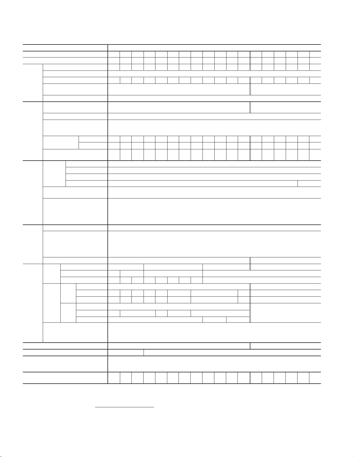
1. Standard Specifications
1.1 Three-phase 230V FRENIC5000G11S Series
Item Specifications
Type FRN■■■■■■G11S-2UX F25 F50 001 002 003 005 007 010 015 020 025 030 040 050 060 075 100 125
Nominal applied motor HP 1/4 1/2 12357.5101520253040506075100125
Rated capacity *1) kVA 0.6 1.2 2.0 3.2 4.4 6.8 9.9 13 18 23 29 36 46 58 72 86 113 138
Rated voltage *2) V 3-phase 200V/50Hz 200, 220, 230V/60Hz
Output Rated current *3) A 1.5 3.0 5.0 8.0 11 17 25 33 46 59 74 87 115 145 180 215 283 346
ratings Overload capability 150% of rated current for 1min. 150% of rated current for 1min.
Rated frequency Hz 50, 60Hz
Phases, Voltage, Frequency 3-phase 200 to 230V 50/60Hz
Voltage / frequency variations Vo ltage : +10 to –15% (Voltage unbalance *4) : 2% or less) Frequency :+5 to –5%
Input *5) When the input voltage drops below 165V from rated voltage, the inverter can be operated for 15ms .
ratings The smooth recovery method is selectable.
Output Accuracy (Stability) •Analog setting : ± 0.2% of Maximum frequency (at 25±10°C (77±50°F))
frequency •Digital setting : ±0.01% of Maximum frequency (at –10 to +50°C (14 to 122°F))
Control 0.1 to 0.9 : Manual (for variable torque load) *9)
Braking Duty cycle
Enclosure (IEC 60529) IP 40 IP 00 ( IP 20 : Option )
Cooling method Natural cooling Fan cooling
Standards -IEC 61800-2 (Ratings, specifications for low voltage adjustable frequency a.c. power drive systems)
Weight lbs 4.9 4.9 5.5 8.4 8.4 8.4 13 13 22 22 23 23 64 79 97 101 154 254
NOTES:
Momentary voltage dip capability When the input voltage is 165V or more, the inverter can be operated continuously.
Rated current *6) (with DCR) 0.94 1.6 3.1 5.7 8.3 14.0 19.7 26.9 39.0 54.0 66.2 78.8 109 135 163 199 272 327
A(without DCR) 1.8 3.4 6.4 11.1 16.1 25.5 40.8 52.6 76.9 98.5 117 136 168 204 243 291 - -
Required power supply
capacity *7)
Maximum frequency 50 to 400Hz
Setting Base frequency 25 to 400Hz
Starting frequency 0.1 to 60Hz, Holding time: 0.0 to 10.0s
Carrier frequency *8) 0.75 to15kHz
Setting resolution •Analog setting : 1/3000 of Maximum frequency ex.) 0.02Hz at 60Hz, 0.04Hz at 120Hz, 0.15Hz at 400Hz
Voltage / freq. (V/f) characteristic Adjustable at base and maximum frequency, with AVR control : 80 to 240V
To rque boost To rque boost can be set, using Function code F09 and A05.
Starting torque 200% (with Dynamic torque-vector control selected)
Braking torque *10) 150% 100% 20% 10 to 15%
Standard
Time s 10 5 5 No limit
Duty cycle
Standard
Braking torque 150% 100%
Time s 90 45 45 45 30 20 10 8 10
Using
options
10%ED Braking torque 150% *12)
Time s 90 45 30 20 10
DC injection braking Starting frequency: 0.1 to 60.0Hz Braking time: 0.0 to 30.0s Braking level: 0 to 100% of rated current
*1) Inverter output capacity (kVA) at 230V. Rated capacity reduces when power supply voltage decreases.
*2) Output voltage cannot exceed the power supply voltage.
*3) Current derating may be required in case of low impedance loads such as high frequency motor.
*4) Use a DC REACTOR (DCR) when the voltage unbalance exceeds 2%. (This value is equivalent to FUJI’s conventional allowable value.)
Voltage unbalance (%) =
*5) Tested at standard load condition (85% load).
*6) This value is under FUJI original calculation method.
*7) When power-factor correcting DC REACTOR (DCR) is used.
*8) When inverter is operating at a carrier frequency of 10kHz or higher, the inverter may automatically reduce the carrier frequency to 8kHz for protecting inverter.
*9) When torque boost is set at 0.1, starting torque of 50% or more can be obtained.
*10) With a nominal applied motor, this value is average torque when the motor decelerates and stops from 60Hz. (It may change according to motor loss.)
*11) Order individually.
*12) Applicable to 10%ED when using options (standard)
Duty cycle
1-2
200% of rated current for 0.5s 180% of rated current for 0.5s
3-phase 200 to 220V/50Hz (220 to 230V/50Hz) *11)
200 to 230V/60Hz
kVA 0.4 0.6 1.1 2.0 2.9 4.9 6.9 9.4 14 19 23 28 38 47 57 69 95 114
•Digital setting : 0.01Hz at Maximum frequency of up to 99.99Hz (0.1Hz at Maximum frequency of 100Hz and above)
• LINK setting : Selects from the following two items.
0.0 : Automatic (for constant torque load)
1.0 to 1.9 : Manual (for propotional speed torque load)
2.0 to 20.0: Manual (for constant torque load)
%ED
10 5 353232 No limit
%ED
37 22 18 10 7 5 5 5 10
%ED
*Inverter restarts at the star ting frequency when operation command is input while braking is operating.
*DC injection braking does not operate at the time of change-over from forward to reverse operation.
*
DC injection braking does not operate when frequency setting is decreased while operation command (FWD, REV) is being input.
-UL/cUL -Low Voltage Directive -EMC Directive -TÜV (up to 30HP)
-IEC 61800-3 (EMC product standard including specific test methods)
(kg) (2.2) (2.2) (2.5) (3.8) (3.8) (3.8) (6.1) (6.1) (10) (10) (10.5) (10.5) (29) (36) (44) (46) (70) (115)
Max. voltage [V] – Min. Voltage [V]
Three-phase average voltage[V]
• 1/20000 of Maximum frequency ex.) 0.003Hz at 60Hz, 0.006Hz at 120Hz, 0.02Hz at 400Hz
• 0.01Hz (Fixed)
180% (with Dynamic torque-vector control selected)
10 10 10
x 67 (Conforming to EN61800-3 (5.2.3))
0.75 to 10kHz
Page 9

Chapter 1
1. Standard Specifications
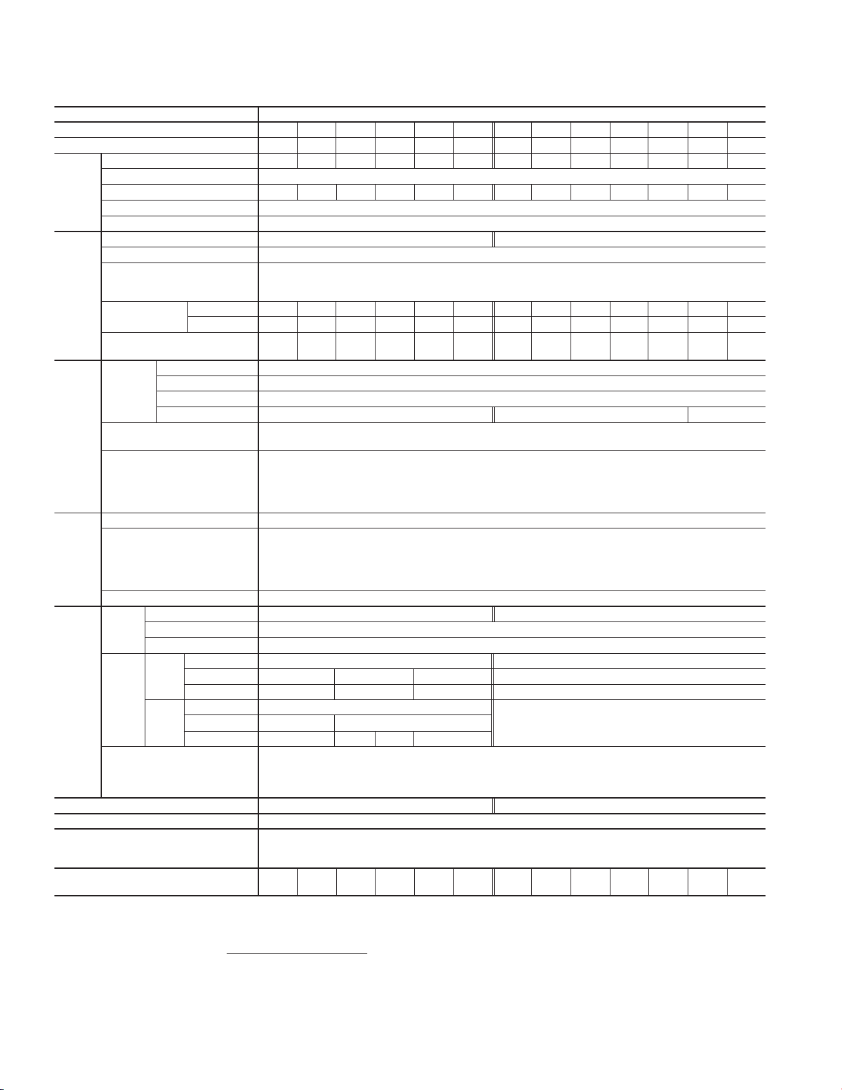
1.2 Three-phase 460V FRENIC5000G11S Series
Item Specifications
Type FRN■■■■■■G11S-4UX F50 001 002 003 005 007 010 015 020 025 030 040 050 060 075 100 125 150 200 250 300 350 400 450 500 600
Nominal applied motor HP 1/2 12357.5101520253040506075100125150200250300350400450500600
Rated capacity *1) kVA 1.1 1.9 2.8 4.1 6.8 9.9 13 18 22 29 34 45 57 69 85 114 134 160 192 231 287 316 396 445 495 563
Rated voltage *2) V 3-phase 380, 400, 415V/50Hz 380, 400, 440, 460V/60Hz
Output Rated current *3) A 1.5 2.5 3.7 5.5 9 13 18 24 30 39 45 60 75 91 112 150 176 210 253 304 377 415 520 585 650740
ratings Overload capability 150% of rated current for 1min. 150% of rated current for 1min.
Rated frequency Hz 50, 60Hz
Phases, Voltage, Frequency 3-phase 380 to 480V 50/60Hz 3-phase 380 to 440V/50Hz 380 to 480V/60Hz *4)
Voltage / frequency variations Vo ltage : +10 to –15% (Voltage unbalance *5) : 2% or less) Frequency :+5 to –5%
Input *6) When the input voltage drops below 310V from rated voltage, the inverter can be operated for 15ms .
ratings The smooth recovery method is selectable.
Output Accuracy (Stability) •Analog setting : ±0.2% of Maximum frequency (at 25±10°C (77±50°F))
frequency •Digital setting : ±0.01% of Maximum frequency (at –10 to +50°C (14 to 122°F))
Control 0.1 to 0.9 : Manual (for variable torque load) *10)
Braking Duty cycle
Enclosure (IEC 60529) IP 40 IP 00 ( IP 20 : Option )
Cooling method
Standards -IEC 61800-2 (Ratings, specifications for low voltage adjustable frequency a.c. power drive systems)
Weight lbs 4.9 5.5 8.4 8.4 8.4 14 14 22 22 23 64 75 86
NOTES: *1) Inverter output capacity (kVA) at 460V. Rated capacity reduces when power supply voltage decreases.
Momentary voltage dip capability When the input voltage is 310V or more, the inverter can be operated continuously.
Rated current *7) (with DCR)
A(without DCR) 1.8 3.5 6.2 9.2
Required power supply
capacity *8)
Maximum frequency 50 to 400Hz
Setting Base frequency 25 to 400Hz
Starting frequency 0.1 to 60Hz, Holding time: 0.0 to 10.0s
Carrier frequency *9) 0.75 to 15kHz 0.75 to 10kHz
Setting resolution •Analog setting : 1/3000 of Maximum frequency ex.) 0.02Hz at 60Hz, 0.04Hz at 120Hz, 0.15Hz at 400Hz
Voltage / freq. (V/f) characteristic Adjustable at base and maximum frequency, with AVR control : 320 to 480V
To rque boost To rque boost can be set, using Function code F09 and A05.
Starting torque 200% (with Dynamic torque-vector control selected) 180% (with Dynamic torque-vector control selected)
Braking torque *11) 150% 100% 20% 10 to 15%
Standard
Time s 55 No limit
Duty cycle
Standard
Braking torque 150% 100%
Time s 45 30 20 10 8 10
Using
options
10%ED Braking torque 150% *13)
Time s 45 30 20 10
Duty cycle
DC injection braking Starting frequency: 0.1 to 60.0Hz Braking time: 0.0 to 30.0s Braking level: 0 to 100% of rated current
*2) Output voltage cannot exceed the power supply voltage.
*3) Current derating may be required in case of low impedance loads such as high frequency motor.
*4) When the input voltage is 380 to 398V/50Hz or 380 to 430V/60Hz, the tap of the auxiliary transformer must be changed.
*5) Use a DC REACTOR (DCR) when the voltage unbalance exceeds 2%. (This value is equivalent to FUJI’s conventional allowable value.)
Voltage unbalance (%) =
*6) Tested at standard load condition (85% load).
*7) This value is under FUJI original calculation method.
*8) When power-factor correcting DC REACTOR (DCR) is used.
*9) When inverter is operating at a carrier frequency of 10kHz or higher, the inverter may automatically reduce the carrier frequency to 8kHz for protecting inverter.
*10) When torque boost is set at 0.1, starting torque of 50% or more can be obtained.
*11) With a nominal applied motor, this value is average torque when the motor decelerates and stops from 60Hz. (It may change according to motor loss.)
*12) Consult with Fuji Electric.
*13) Applicable to 10%ED when using options (standard)
200% of rated current for 0.5s 180% of rated current for 0.5s
0.82
1.5 2.9 4.2 7.1
kVA 0.6 1.1 2.1 3.0 5.0 7.0 9.4 14 19 24 28 38 47 57 70 93 111 136 161 196 244 267 341 383 433 488
•Digital setting : 0.01Hz at Maximum frequency of up to 99.99Hz (0.1Hz at Maximum frequency of 100Hz and above)
• LINK setting : Selects from the following two items.
0.0 : Automatic (for constant torque load)
1.0 to 1.9 : Manual (for propotional speed torque load)
2.0 to 20.0: Manual (for constant torque load)
%ED
5353232 No limit
%ED
22 18 10 7 5 5 5 10
%ED
(kg)
Max. voltage [V] – Min. Voltage [V]
Three-phase average voltage[V]
10 10 10 10
*Inverter restarts at the starting frequency when operation command is input while braking is operating.
* DC injection braking does not operate at the time of change-over from forward to reverse operation.
*
DC injection braking does not operate when frequency setting is decreased while operation command (FWD, REV) is being input.
Natural cooling
-UL/cUL -Low Voltage Directive -EMC Directive -TÜV (up to 30HP)
-IEC 61800-3 (EMC product standard including specific test methods)
(2.2) (2.5) (3.8) (3.8) (3.8) (6.5) (6.5) (10) (10)
10.0 13.5 19.8 26.8 33.2 39.3
14.9 21.5 27.9 39.1 50.3 59.9 69.3
• 1/20000 of Maximum frequency ex.) 0.003Hz at 60Hz, 0.006Hz at 120Hz, 0.02Hz at 400Hz
• 0.01Hz (Fixed)
(10.5) (10.5)
x 67 (Conforming to EN61800-3 (5.2.3))
54 67 81 100 134 160 196 232 282 352 385 491 552 624 704
86 104 124150 -----------
Fan cooling
23
(29) (34)
88 106 154 154 221 221 309 309 551 551 794 794
(70)(70)(48)(40)(39)
(100) (100)
(140)
(140)
(250) (250) (360)
(360)
1
1-3
Page 10
Chapter 1
1. Standard Specifications
1.3 Three-phase 230V FRENIC5000P11S Series (for variable torque load)
Item Specifications
Type FRN■■■■■■P11S-2UX 007 010 015 020 025 030 040 050 060 075 100 125 150
Nominal applied motor HP 7.5 10 15 20 25 30 40 50 60 75 100 125 150
Rated capacity *1) kVA 8.8 12 17 22 27 31 46 58 72 86 113 138 165
Rated voltage *2) V 3-phase 200V/50Hz 200, 220, 230V/60Hz
Output Rated current *3) A 22 29 42 55 67 78 115 145 180 215 283 346 415
ratings Overload capability 110% of rated current for 1min
Rated frequency Hz 50, 60Hz
Phases, Voltage, Frequency 3-phase 200 to 230V 50/60Hz
Voltage / frequency variations Vo ltage : +10 to –15% (Voltage unbalance *4) : 2% or less) Frequency :+5 to –5%
Input *5) When the input voltage drops below 165V from rated voltage, the inverter can be operated for 15ms .
ratings The smooth recovery method is selectable.
Output Accuracy (Stability) •Analog setting : ± 0.2% of Maximum frequency (at 25±10°C (77±50°F))
frequency •Digital setting : ±0.01% of Maximum frequency (at –10 to +50°C (14 to 122°F))
Control 0.1 to 0.9 : Manual (for variable torque load) *9)
Braking Duty cycle
Enclosure (IEC 60529) IP 40 IP 00 ( IP 20 : Option )
Cooling method Fan cooling
Standards -IEC 61800-2 (Ratings, specifications for low voltage adjustable frequency a.c. power drive systems)
Weight lbs 13 13 13 22 22 23 64 64 79 97 101 154 254
NOTES: *1) Inverter output capacity (kVA) at 230V. Rated capacity reduces when power supply voltage decreases.
Momentary voltage dip capability When the input voltage is 165V or more, the inverter can be operated continuously.
Rated current *6) (with DCR) 19.7 26.9 39.0 54.0 66.2 78.8 109 135 163 199 272 327 400
A(without DCR) 40.8 52.6 76.9 98.5 117 136 168 204 243 291 - - -
Required power supply
capacity *7)
Maximum frequency 50 to 120Hz
Setting Base frequency 25 to 120Hz
Starting frequency 0.1 to 60Hz, Holding time: 0.0 to 10.0s
Carrier frequency *8) 0.75 to 15kHz 0.75 to 10kHz 0.75 to 6kHz
Setting resolution •Analog setting : 1/3000 of Maximum frequency ex.) 0.02Hz at 60Hz, 0.04Hz at 120Hz
Voltage / freq. (V/f) characteristic Adjustable at base and maximum frequency, with AVR control : 80 to 240V
To rque boost To rque boost can be set, using Function code F09 and A05.
Starting torque 50%
Braking torque *10) 20% 10 to 15%
Standard
Time s No limit
Duty cycle
Standard
Braking torque 100% 75%
Time s 15 7 8 10
Using
options
10%ED Braking torque 100% *12)
Time s 15 7
Duty cycle
DC injection braking Starting frequency: 0.1 to 60.0Hz Braking time: 0.0 to 30.0s Braking level: 0 to 100% of rated current
*2) Output voltage cannot exceed the power supply voltage.
*3) Current derating may be required in case of low impedance loads such as high frequency motor.
*4) Use a DC REACTOR (DCR) when the voltage unbalance exceeds 2%. (This value is equivalent to FUJI’s conventional allowable value.)
Voltage unbalance (%) =
*5) Tested at standard load condition (85% load).
*6) This value is under FUJI original calculation method.
*7) When power-factor correcting DC REACTOR (DCR) is used.
*8) When inverter is operating at a carrier frequency of 10kHz or higher, the inverter may automatically reduce the carrier frequency to 8kHz for protecting inverter.
*9) When torque boost is set at 0.1, starting torque of 50% or more can be obtained.
*10) With a nominal applied motor, this value is average torque when the motor decelerates and stops from 60Hz. (It may change according to motor loss.)
*11) Order individually.
*12) Applicable to 10%ED when using options (standard)
kVA 6.9 9.4 14 19 23 28 38 47 57 69 95 114 139
•Digital setting : 0.01Hz at Maximum frequency of up to 99.99Hz (0.1Hz at Maximum frequency of 100Hz and above)
• LINK setting : Selects from the following two items.
0.0 : Automatic (for constant torque load)
1.0 to 1.9 : Manual (for propotional speed torque load)
2.0 to 20.0 : Manual (for constant torque load)
%ED
%ED
%ED
(kg) (5.7) (5.7) (5.7) (10) (10) (10.5) (29) (29) (36) (44) (46) (70) (115)
Max. voltage [V] – Min. Voltage [V]
Three-phase average voltage[V]
3.5 3.5 4 10
10 10 10 7
* Inverter restarts at the starting frequency when operation command is input while braking is operating.
* DC injection braking does not operate at the time of change-over from forward to reverse operation.
*
DC injection braking does not operate when frequency setting is decreased while operation command (FWD, REV) is being input.
-UL/cUL -Low Voltage Directive -EMC Directive -TÜV (up to 30HP)
-IEC 61800-3 (EMC product standard including specific test methods)
• 1/20000 of Maximum frequency ex.) 0.003Hz at 60Hz, 0.006Hz at 120Hz
• 0.01Hz (Fixed)
x 67 (Conforming to EN61800-3 (5.2.3))
3-phase 200 to 220V/50Hz (220 to 230V/50Hz) *11) 200 to 230V/60Hz
No limit
1-4
Page 11
Chapter 1
1. Standard Specifications
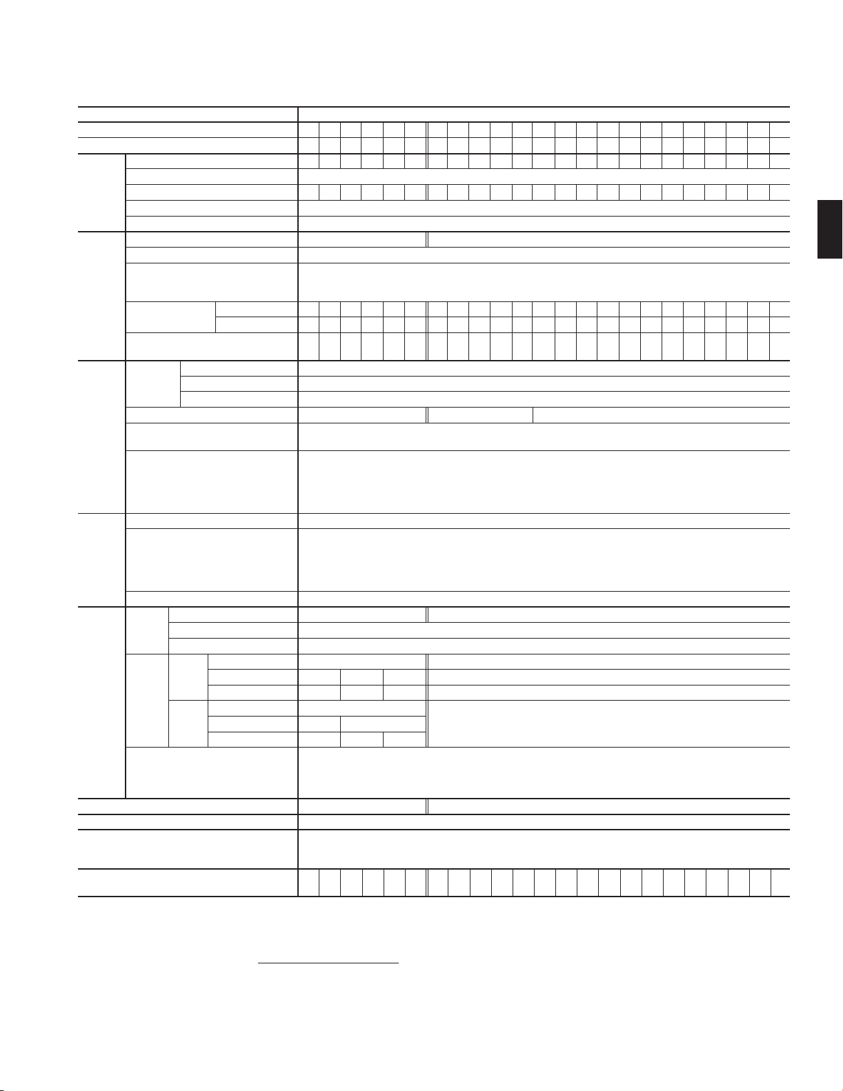
1.4 Three-phase 460V FRENIC5000P11S Series (for variable torque load)
Item Specifications
Type FRN■■■■■■P11S-4UX 007 010 015 020 025 030 040 050 060 075 100 125 150 200 250 300 350 400 450 500 600 700 800
Nominal applied motor HP 7.5 10 15 20 25 30 40 50 60 75 100 125 150 200 250 300 350 400 450 500 600 700 800
Rated capacity *1) kVA 10 13 18 24 29 35 48 60 72 89 119 140 167 201 242 300 330 386 414 517 589 668 764
Output
raitings
Input *6) When the input voltage drops below 310V from rated voltage, the inverter can be operated for 15ms .
ratings The smooth recovery method is selectable.
Output Accuracy (Stability) ·Analog setting : ±0.2% of Maximum frequency (at 25±10°C (77±50°F))
frequency ·Digital setting : ±0.01% of Maximum frequency (at –10 to +50°C (14 to 122°F))
Control 0.1 to 0.9 : Manual (for variable torque load) *10)
Braking Duty cycle
Enclosure (IEC 60529) IP 40 IP 00 ( IP 20 : Option )
Cooling method Fan cooling
Standards -IEC 61800-2 (Ratings, specifications for low voltage adjustable frequency a.c. power drive systems)
Weight lbs 13 13 13 22 22 23 64 64 75 86 88 106 154 154 221 221 309 309 309 551 551 794 794
NOTES:
Rated voltage *2) V 3-phase 380, 400, 415V/50Hz 380, 400, 440, 460V/60Hz
Rated current *3) A
Overload capability 110% of rated current for 1min
Rated frequency Hz 50, 60Hz
Phases, Voltage, Frequency
Voltage / frequency variations Voltage : +10 to –15% (Voltage unbalance *5) : 2% or less) Frequency :+5 to –5%
Momentary voltage dip capability When the input voltage is 310V or more, the inverter can be operated continuously.
Rated current *7) (with DCR)
A(without DCR)
Required power supply
capacity *8)
Maximum frequency 50 to 120Hz
Setting Base frequency 25 to 120Hz
Starting frequency 0.1 to 60Hz, Holding time: 0.0 to 10.0s
Carrier frequency *9) 0.75 to 15kHz 0.75 to 10kHz 0.75 to 6kHz
Setting resolution ·Analog setting : 1/3000 of Maximum frequency ex.) 0.02Hz at 60Hz, 0.04Hz at 120Hz
Voltage / freq. (V/f) characteristic Adjustable at base and maximum frequency, with AVR control : 320 to 480V
To rque boost Torque boost can be set, using Function code F09 and A05.
Starting torque 50%
Braking torque *11) 20% 10 to 15%
Standard
Time s No limit
Duty cycle
Standard
Braking torque 100% 75%
Time s 15 7 8 10
Using
options
10%ED Braking torque 100% *13)
Time s 15 7
Duty cycle
DC injection braking Starting frequency: 0.1 to 60.0Hz Braking time: 0.0 to 30.0s Braking level: 0 to 100% of rated current
*1) Inverter output capacity (kVA) at 460V. Rated capacity reduces when power supply voltage decreases.
*2) Output voltage cannot exceed the power supply voltage.
*3) Current derating may be required in case of low impedance loads such as high frequency motor.
*4) When the input voltage is 380 to 398V/50Hz or 380 to 430V/60Hz, the tap of the auxiliary transformer must be changed.
*5) Use a DC REACTOR (DCR) when the voltage unbalance exceeds 2%. (This value is equivalent to FUJI’s conventional allowable value.)
Voltage unbalance (%) =
*6) Tested at standard load condition (85% load).
*7) This value is under FUJI original calculation method.
*8) When power-factor correcting DC REACTOR (DCR) is used.
*9) When inverter is operating at a carrier frequency of 10kHz or higher, the inverter may automatically reduce the carrier frequency to 8kHz for protecting inverter.
*10) When torque boost is set at 0.1, starting torque of 50% or more can be obtained.
*11) With a nominal applied motor, this value is average torque when the motor decelerates and stops from 60Hz. (It may change according to motor loss.)
*12) Consult with Fuji Electric.
*13) Applicable to 10%ED when using options (standard)
Max. voltage [V] – Min. Voltage [V]
Three-phase average voltage[V]
12.5 16.5
3-phase 380 to 480V 50/60Hz
10.0 13.5 19.8 26.8 33.2 39.3
21.5 27.9 39.1 50.3 59.9 69.3
kVA 7.0 9.4 14 19 24 28 38 47 57 70 93 111 136 161 196 244 267 341 383 433 488 549 610
·Digital setting : 0.01Hz at Maximum frequency of up to 99.99Hz (0.1Hz at Maximum frequency of 100Hz and above)
· LINK setting : Selects from the following two items.
%ED
%ED
%ED
* Inverter restarts at the starting frequency when operation command is input while braking is operating.
* DC injection braking does not operate at the time of change-over from forward to reverse operation.
*
-UL/cUL -Low Voltage Directive -EMC Directive -TÜV (up to 30HP)
-IEC 61800-3 (EMC product standard including specific test methods)
(kg)
(6.1) (6.1) (6.1)
23 30 37 44 60 75 91 112 150 176 210 253 304 377 415 520 585 650 740 840 960
3-phase 380 to 440V/50Hz 380 to 480V/60Hz *4)
54 67 81 100 134 160 196 232 282 352 385 491 552 624 704 792 880
86 104 124 150 - ------------
• 1/20000 of Maximum frequency ex.) 0.003Hz at 60Hz, 0.006Hz at 120Hz
• 0.01Hz (Fixed)
0.0 : Automatic (for constant torque load)
1.0 to 1.9 : Manual (for propotional speed torque load)
2.0 to 20.0 : Manual (for constant torque load)
No limit
3.5 3.5 4 10
10 10 7
DC injection braking does not operate when frequency setting is decreased while operation command (FWD, REV) is being input.
(10) (10)
(10.5)
(29) (29) (34) (39) (40) (70) (70)
x 67 (Conforming to EN61800-3 (5.2.3))
(48)
(100) (100) (140) (140) (140) (250) (250) (360) (360)
1
1-5
Page 12
Chapter 1
FWD
2. Common Specifications
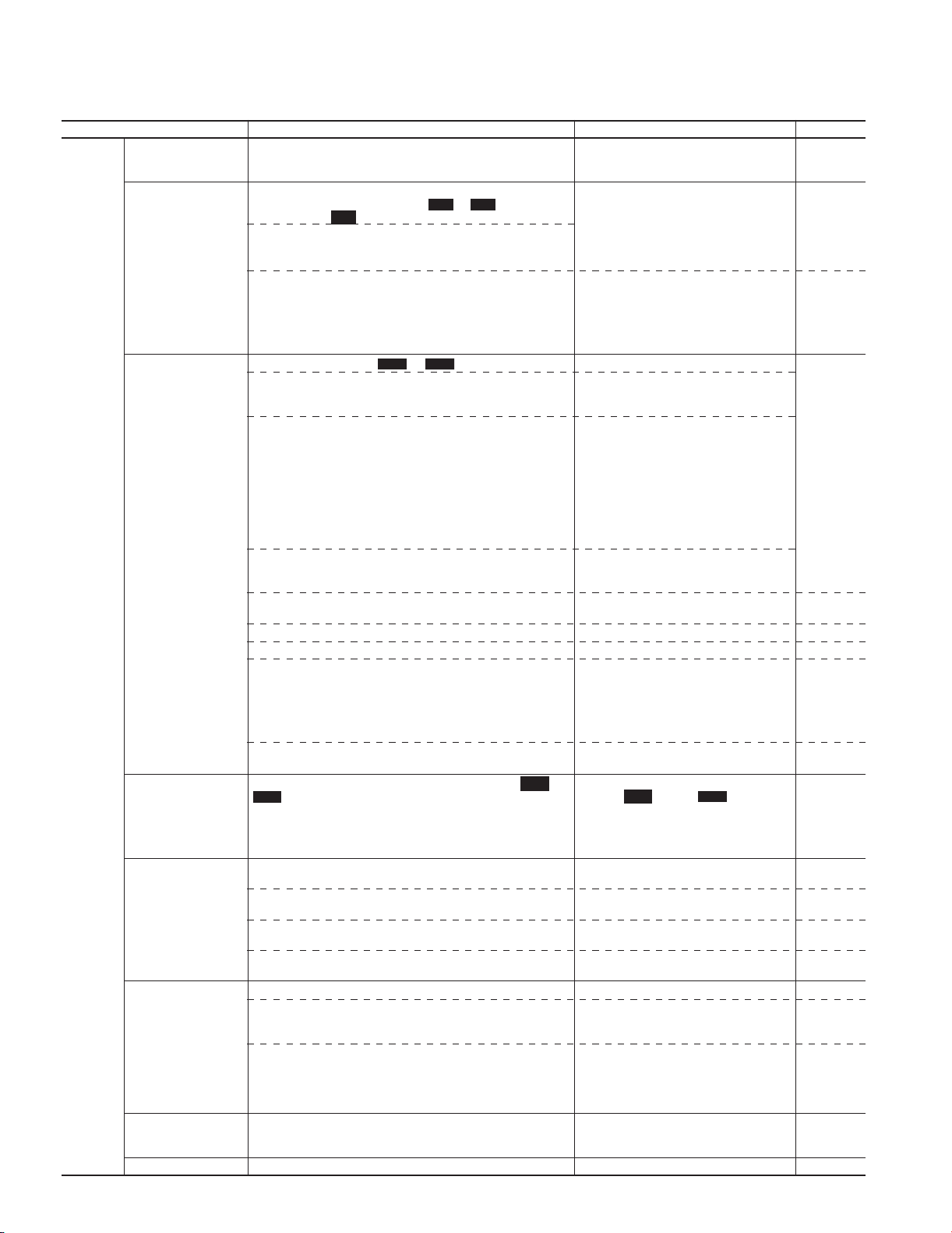
2. Common Specifications
2.1 Outline of common specifications
Item Explanation Remarks Func. code
Control Control method
Operation method F02
Frequency setting F01
(Frequency command)
Jogging operation C20
Running status signal E20 to E23
Acceleration/ F07, F08
Deceleration time E10 to E15
Active drive H19
Frequency limiter F15, F16
NOTE : ( ) or < > in the “Remarks” column indicates the abbreviation of terminal function assigned to digital input terminals X1 to X9 and
1-6
transistor output terminals Y1 to Y5C.
•V/f control (Sinusoidal PWM control)
• Dynamic torque-vector control (Sinusoidal PWM control)
•Vector control with PG ...G11S only
• KEYPAD operation :
Forward or reverse operation by
Stopping by
• Digital input signal operation :
FWD·STOP command, REV·STOP command, Coast-to-stop
command, etc.
• LINK operation :
• RS-485 (standard)
• Various Bus interface is available. (Option)
• T-Link (FUJI private link) • Devicenet • CAN open
• Profibus-DP • Modbus Plus
• Interbus-S •JPCN1
• KEYPAD operation :
• External potentiometer : Variable resistor (1 to 5kΩ 1/2W)
• Analog input : External voltage or current input
(Reversible
operation)
(Inverse
operation)
• UP/DOWN control :
Output frequency increases when UP signal is ON, and
decreases when DOWN signal is ON.
• Multistep frequency selection :
Up to 16 different frequencies can be selected by digital input signal.
• Pulse train input : 0 to 100kp/s
• Digital signal (parallel) :
• LINK operation : RS-485 (standard) (RS-485FGABus)
Programmed PATTERN operation : Max. 7 stages
This operation can be performed by KEYPAD opration (
key) or digital input signal (FWD or REV).
REV
Transistor output : RUN, FAR, FDT, OL, LU, TL, etc.
(4 points) (4 output types are selectable)
Relay output : • Same as transistor output.
(2 points) • Alarm output (for any fault)
Analog output : Output frequency, Output current,
(1 point) Output voltage, Output torque, etc.
Pulse output : Output frequency, Output current,
(1 point) Output voltage, Output torque, etc.
0.01 to 3600s
Four kinds of acceleration and deceleration times can be set
independently, and the desired time is selected by combining
digital input signal (2 points).
Selects acceleration/deceleration pattern from the following 4 types.
• Linear
• S-curve (weak)
• S-curve (strong)
• Non-linear (for variable torque load)
When the acceleration time reaches 60s, the motor output torque
is automatically reduced to rated torque. Then the motor operation
mode is changed to torque limiting operation.
High and Low frequency limiters can be preset.
key
STOP
∨
0 to +10Vdc (0 to +5Vdc)
4 to 20mAdc
: Reversible operation by polarized signal can be
selected.
0 to ± 10Vdc (0 to ± 5Vdc)
: Inverse mode operation can be selected by
digital input signal (IVS).
0 to +10Vdc → 10 to 0Vdc (terminal 12)
4 to 20mAdc → 20 to 4mAdc (terminal C1)
12-bit parallel (12-bit binary) signal can be input.
(Option) • T-Link (FUJI private link)
• Profibus-DP
• Interbus-S
• Modbus Plus
• Devicenet
or
FWD
or ∨ key
REV
key
,
Option card (PG/Hz) required.
Switching between KEYPAD operation and
digital input signal operation is enabled by
pressing STOP key and RESET key at the
same time.
(LE)
• Connect to terminals 13, 12, and 11.
• Set Function code at ”F01: 1".
• Potentiometer is required separately.
0 to +5Vdc, 0 to ± 5Vdc input is enabled
when Func. code 17 (Gain for frequency
setting) is set at 200.0%.
(UP, DOWN)
(SS1, SS2, SS4, SS8)
Option card (PG/SY) required.
Option card (DIO) required.
(LE)
Option card for open networks
<STG1, STG2, STG4, TU, TO>
• To enter jogging operation mode:
•Press
same time.
•Digital input signal : (JOG)
* During jogging operation, an indicator at
“JOG” is lit on the LCD monitor.
Coast-to-stop is selectable by Function code “H11”.
(RT1, RT2)
The acceleration time is automatically
extended up to 3 times.
STOP
key and
∨
key at the
F42, A09
H30 to H39
C05 to C19
H31 to H39
F01
C21 to C28
F02
F36
E24, E25
F31
F35
H07
Page 13

Chapter 1
∨
2. Common Specifications
Item Explanation Remarks Func. code
Control Bias frequency F18
Gain for frequency F17
setting
Jump frequency control C01 to C04
Rotating motor pick up H09
(Flying start)
Auto-restart after F14
momentary power failure
Line/Inverter
changeover operation
Slip compensation P09
Droop operation H28
Torque limiting F40, F41
Torque control H18
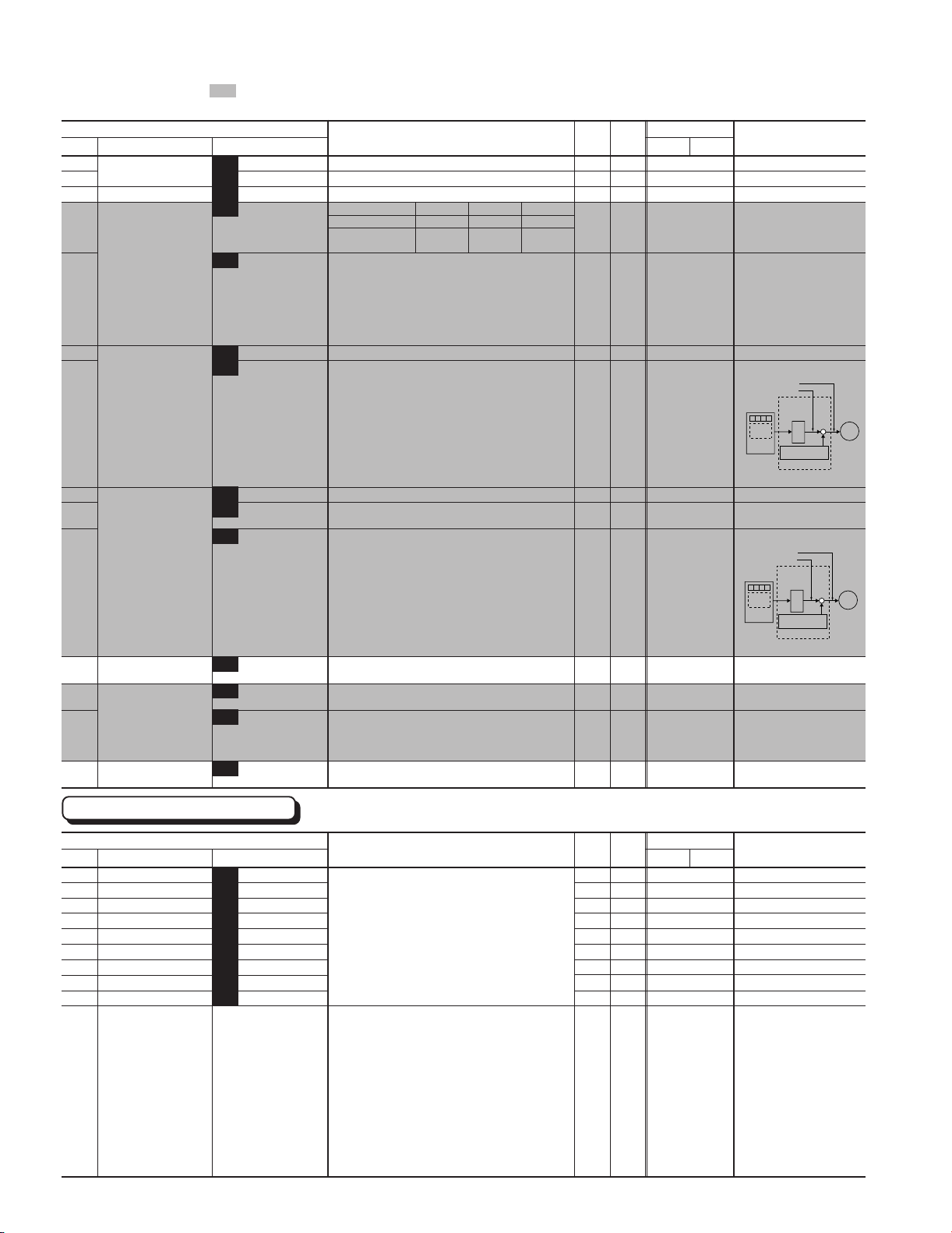
PID control H20 to H25
Automatic deceleration F41, E17
Second motor's setting A01 to A18
Energy saving operation H10
Fan stop operation H06
Universal DI
Universal DO
Bias frequency can be preset.
Gain for frequency setting can be preset. (0.0 to 200.0%)
ex.) Analog input 0 to +5Vdc with 200% gain results in
Maximum frequency at 5Vdc.
Jump frequency (3 points) and its common jump hysteresis width
(0 to 30Hz) can be preset.
A rotating motor(including inverse rotating mode) can be smoothly
picked up without stopping the motor. (speed search method)
Automatic restart is available without stopping motor after a
momentary power failure. (speed search method)
When "Smooth recovery" mode is selected, the motor speed drop
is held minimum.
Controls switching operation between line power and inverter.
The inverter has sequence function inside.
• The inverter output frequency is controlled according to the load
torque to keep motor speed constant.
• When the value is set at "0.00" and "Torque-vector" is set at "active", the
compensation value automatically selects the Fuji standard motor.
Slip compensation can be preset for the second motor.
The motor speed droops in proportional to output torque.(-9.9 to
0.0Hz) ...G11S only
When the motor torque reaches a preset limiting level, this function
automatically adjusts the output frequency to prevent the inverter
from tripping due to an overcurrent.
To rque limiting 1 and Torque limiting 2 can be individually set, and
are selectable with a digital input signal.
Output torque (or load factor ) can be controlled with an analog
input signal (terminal 12).
This function can control flowrate, pressure, etc. (with an analog feedback signal.)
••
• Reference signal
••
• KEYPAD operation (
Setting freq. / Maximum freq. X 100 [%]
•Voltage input (terminal 12 and V2) : 0 to 10Vdc / 0 to 100%
•Current input (terminal C1) : 4 to 20mAdc / 0 to 100%
• Reversible operation with polarity (terminal 12) :
0 to ± 10Vdc / 0 to ±100%
•Reversible operation with polarity (terminal 12 + V1) :
0 to ± 10Vdc / 0 to ± 100%
•Inverse mode operation (terminal 12 and V2) : 10 to 0Vdc / 0 to 100%
• Inverse mode operation (terminal C1) : 20 to 4mAdc / 0 to 100%
• PATTERN operation : Setting freq. / Maximum freq. X 100 [%]
•DI option input : • BCD...Setting freq. / Maximum freq. X 100 [%]
• Multistep frequency setting :
• RS-485 : Setting freq. / Maximum freq. X 100 [%]
••
• Feedback signal
••
• Terminal 12 (0 to 10Vdc / 0 to 100%, or 10 to 0Vdc / 0 to 100% )
• Terminal C1 (4 to 20mAdc / 0 to 100%, or 20 to 4mAdc / 0 to 100%)
Torque limiter 1 (Braking) is set at "F41: 0".
• In deceleration :
The deceleration time is automatically extended up to 3 times for
tripless operation even if a braking resistor is not used.
• In constant speed operation :
Based on regenerative energy, the frequency is increased, and
tripless operation is active.
This function is used for two motors switching operation.
• The second motor's V/f characteristics (base and maximum frequency),
rated current, torque boost, electronic thermal relay, etc. can be preset.
• The second motor's circuit parameter can be preset, and torquevector control can be applied to both motors.
This function minimizes inverter and motor losses at light load.
• This function detects temperature inside inverter to stop cooling
fans for silent operation and extending the fans' lifetime.
•On/off status of cooling fans is output.
Transmits to main controller of LINK operation
Outputs command signal from main controller of LINK operation.
∨
or
• Binary...Full scale / 100%
(Setting of Torque limiter 2 (Braking) is same.)
key) :
Setting freq. / Maximum freq. X 100
NOTE : ( ) or < > in the “Remarks” column indicates the abbreviation of terminal function assigned to digital input terminals X1 to X9 and
transistor (relay) output terminals Y1 to Y4 (Y5A, Y5C).
When the sum of setting frequency and bias
frequency is minus value, the output
frequency rise can be delayed. (No reverse
running is performed.)
(STM)
The inverter searches the motor speed, and
smoothly returns to setting frequency.
Even if the motor circuit is temporarily opened,
the inverter operates without a hitch.
(SW50, SW60)
<SW88, SW52-1, SW52-2>
Slip compensation value can be manually
set from 0.01 to 5.00Hz instead of 0.0 for
FUJI standard motor.
P11S series doesn't have this function.
(TL2/TL1)
• Torque polarity selectable. (Hz/TRQ)
• P11S series doesn't have this function.
• PID control is selected by "H20". (Hz/PID).
• Reference signal selection is made by "F01".
In "F01", "8: UP/DOWN control 1", "9: UP/
DOWN control 2", and "11: Pulse train
input" cannot be used for the reference
signal of PID control.
• Terminal V1 is optional.
• Terminal V2: EN only
[%
]
• Feedback signal selection is made by "H21".
When the deceleration time is extended to
longer than three times the setting time, the
inverter trips.
(M2/M1)
<SWM2>
<FAN>
(U-DI)
<U-DO>
H13 to H16
E01 to E09
E20 to E24, H13
A18
E16, E17
F01
C05 to C19
H21
1
1-7
Page 14

Chapter 1
2. Common Specifications
Item Explanation Remarks Func. code
Control Zero speed control
Positioning control
Synchronized operation
Protection Overload
Overvoltage
Surge protection
Undervoltage
Input phase loss
Overheating
Short-circuit
Ground fault
Motor overload F10 to F12
(Overload early warning) E33 to E35
DB resistor overheating F13
Output phase loss
detection
Motor protection by H26, H27
PTC thermistor
Auto reset H04, H05
Condition Installation location
(Installation
and
operation)
Storage condition
Ambient temperature
Ambient humidity
Altitude
Vibration
The stopped motor holds its rotor angle. For a rotating motor, the
rotor angle is held after deceleration.
The SY option card can be used for positioning control by
differential counter method.
This function controls the synchronized operation between 2 axes with PGs.
Protects the inverter by electronic thermal and detection of inverter temperature.
Detects DC link circuit overvoltage, and stops the inverter.
Protects the inverter against surge voltage between the main
circuit power line and ground.
Detects DC link circuit undervoltage, and stops the inverter.
Phase loss protection for power line input
Protects the inverter by detection of inverter heat sink temperature.
Short-circuit protection for inverter output circuit
• Ground fault protection for inverter output circuit (3-phase current
• Zero-phase current detection method
• The inverter trips, and then protects the motor.
• Electronic thermal overload relay can be selected for standard
• The second motor's electronic thermal overload relay can be
• Before the inverter trips, outputs OL(Overload early warning)
• Prevents DB resistor overheating by internal electronic thermal
•Prevents DB resistor overheating by external thermal overload
When the inverter executes auto-tuning, detects each phase
impedance imbalance (and stops the inverter).
When the motor temperature exceeds allowable value, the inverter
trips automatically.
When the inverter is tripped, it resets automatically and restarts.
• Indoor use only.
• Free from corrosive gases, flammable gases, oil mist, dusts, and
-10 to +50˚C (14 to +122˚F) (For inverters of 30HP or smaller, remove the
ventilation covers when operated at temperature of 40˚C (104˚F)or above.)
5 to 95%RH (non-condensing)
33ft (1000m) or less. Applicable to 9800ft (3000m) with power
derating (-10% / 33ft (1000m))
3mm (vibration amplitude) at 2 to less than 9Hz
9.8m/s
2m/s2 at 20 to less than 55Hz (2m/s2 at 9 to less than 55Hz : G11S
125HP, P11S 150HP or more)
1m/s
• Temperature : -25 to +65°C (-13 to +149°F)
• Humidity : 5 to 95%RH (No-condensing)
detection method)
motor or inverter motor
preset for 2-motor changeover operation.
signal at a preset level.
overload relay. (10HP or smaller for G11S, 15HP or smaller for
P11S)
relay attached to DB resistor. (15HP or larger for G11S, 20HP or
larger for P11S)
direct sunlight.
2
at 9 to less than 20Hz
2
at 55 to less than 200Hz
A motor with PG and option card (OPCG11S-PG) are necessary. (ZERO)
P11S series doesn't have this function.
Option card (PG/SY) required
Option card is required.
230V : 400Vdc, 460V : 800Vdc
• Line voltage : 5kV
• Between power line and ground : 7kV (1.2/50µs)
230V : 200Vdc, 460V : 400Vdc
•
Operation details are selected by Function code F14.
• 30HP or smaller inverter
• 40HP or larger inverter
• Thermal time constant (0.5 to 75.0
minutes) can be preset for a special motor.
• External singnal is used for changeover.
Related transistor output : OL
<OL1, OL2>
• The inverter stops electricity discharge
operation, to protect the DB resistor.
Then, usually inverter displays "OU trip".
• Connects the relay output to the terminal
THR, to protect the DB resistor.
Then, usually the inverter displays "OH trip".
Number of Auto reset times and reset
interval can be preset.
Pollution degree 2 when complying with Low
Voltage Directive is needed.
*
When altitude is 6600ft (2000m) or higher,
interface circuit should be isolated from main
power lines, to comply with Low Voltage Directive.
F14
A06 to A08
1-8
Item Explanation Remarks Func. code Explanation Func. code
Indication Operation mode
(Running)
LED monitor
The following items can be displayed
by function setting.
• Output frequency 1 (Before slip
compensation) [Hz]
• Output frequency 2 (After slip
compensation) [Hz]
• Setting frequency [Hz]
• Output current [A]
• Output voltage [V]
• Motor synchronous speed [r/min]
• Line speed [m/min]
• Load shaft speed [r/min]
• Torque calculation value [%]
• Input power [kW]
• PID reference value
• PID reference value (remote)
• PID feedback value
• Trip history
Cause of trip of the
last 4 trips can be
retained and
displayed. (Even
when main power is
off, data is retained.)
• PG feedback value
is displayed when
PG option is used.
E43
F01
C30
LCD monitor
Languages for the LCD monitor are
selectable.
English, German, French, Spanish, Italian,
Japanese
Operation monitor & Alarm monitor
• Operation monitor
Two types of monitoring is selectable by "E45".
• Displays operation guidance
• Bargraph
• Output frequency (before slip
compensation) [%]
• Output current [A]
• Output torque [%]
• Alarm monitor
When the inverter trips, displays the alarm.
E46
E45
Page 15

Chapter 1
2. Common Specifications
Indication Stopping
Item Explanation Remarks Func. code Explanation Func. code
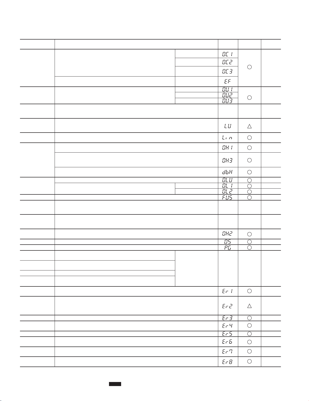
Tri p mode
Charge lamp When the DC link circuit voltage is higher than 50V, the charge lamp is ON.
LED monitor
Selected setting value or output
value
Displays the cause of trip by codes
as follows.
• OC1 (Overcurrent during
acceleration)
• OC2 (Overcurrent during
deceleration)
• OC3 (Overcurrent running at
constant speed)
• EF (Ground fault)
• Lin (Input phase loss)
• FUS (Fuse blown)
• OU1 (Overvoltage during
acceleration)
• OU2 (Overvoltage during
deceleration)
• OU3 (Overvoltage running at
constant speed)
• LU (Undervoltage)
• OH1 (Overheating at heat sink)
• OH2 (External thermal relay tripped)
• OH3 (Overtemperature at inside air)
• dBH (Overheating at DB circuit)
• OL1 (Motor1 overload)
• OL2 (Motor2 overload)
• OLU (Inverter unit overload)
• OS (Overspeed)
• PG (PG error)
• Er1 (Memory error)
• Er2 (KEYPAD panel communication error)
• Er3 (CPU error)
• Er4 (Option communication error)
• Er5 (Option error)
• Er6 (Operation procedure error)
• Er7 (Output phase loss error,
impedance imbalance)
• Er8 (RS-485 error)
• Trip history
Cause of trip of the last
4 trips can be retained
and displayed. (Even
when main power is off,
data are retained.)
E44
LCD monitor
Function setting & monitor
Selectable from the following 7 indications.
••
• Function setting
••
Displays function codes and its data or data code.
•
• Changes the data value.
••
• Operation condition monitoring
••
• Output frequency (before slip compensation)
• Output current [A]
• Output voltage [V]
• Torque calculation value [%]
• Setting frequency [Hz]
• Operation condition
• FWD or REV (Forward or reverse running)
• IL (Current limiting)
• VL or LU (Voltage limiting or stopped by
undervoltage)
• TL (Torque limiting)
• Motor synchronous speed [r/min]
• Load shaft speed [r/min]
• Line speed [m/min]
• PID reference value
• PID feedback value
• Driving torque limiter setting value [%]
• Braking torque limiter setting value [%]
••
• Tester function (I/O check)
••
Displays on/off status of digital input and
output signals, level of analog input and
pulse output signals.
•Digital I/O : ■ (ON), ■■ (OFF)
• Analog I/O: [V] , [mA], [H], [p/s]
••
• Maintenance data
••
• Operation time [h]
• DC link circuit voltage [V]
• Temperature at inside air [°C]
• Temperature at heat sink [°C]
• Maximum current [A]
• Main circuit capacitor life [%]
• Control PC board life [h]
• Cooling fan operation time [h]
• Communication error times (KEYPAD)
• Communication error times (RS-485)
• Communication error times (Option)
• ROM version (Inverter)
• ROM version (KEYPAD)
• ROM version (Option)
••
• Load factor calculation
••
• Measurement time [s]
• Maximum current [A]
• Effective current [A]
• Average braking power [%]
••
• Alarm data
••
Dispalys operation data immediately before
a trip occurs.
• Output frequency (before slip compensation)
• Output current [A]
• Output voltage [V]
• Torque calculation value [%]
• Setting frequency [Hz]
• Operation condition
• FWD or REV (Forward or reverse
running)
• IL (Current limiting)
• VL or LU (Voltage limiting or stopped by
undervoltage)
• TL (Torque limiting)
• Operation time [h]
• DC link circuit voltage [V]
• Temperature at inside air [°C]
• Temperature at heat sink [°C]
• Communication error times (KEYPAD)
• Communication error times (RS-485)
• Communication error times (Option)
• Digital input terminal condition (Remote)
Digital input terminal condition (Communication)
•
• Transistor output terminal condition
• Trip history code
• Multiple alarm exist
••
• Data copy
••
• Function code (data and data code) is
stored in one inverter and is copied to
another inverter *.
* Copying is only available to the inverter
of the same series, same voltage class,
and same capacity .
[Hz]
[Hz]
1
1-9
Page 16
Chapter 1
2. Common Specifications
2.2 Protective functions
Function Description
Overcurrent protection
(Short-circuit)
(Ground fault)
Overvoltage protection
Incoming surge
protection
Undervoltage
protection
Input phase loss
protection
Overheat protection
Electronic thermal
overload relay
(Motor protection)
Fuse blown
Stall prevention
(Momentary
overcurrent limitation)
Active drive
External alarm
input
Overspeed protection
PG error
Alarm output
(for any fault)
Alarm reset command
Alarm history memory
Storage of data on
cause of trip
Memory error
KEYPAD panel
communication error
CPU error
Option
communication error
Option error
Operation
procedure error
Output phase loss
error
RS-485 communication
error
*) ▲▲ : By function code setting, alarm output can be disabled.
NOTES :
1) Retaining alarm signal when auxiliary controll power supply is not used :
2) To issue the RESET command, press the
3) Fault history data is stored for the past four trips.
1-10
• Stops running to protect inverter from an overcurrent resulting from
overload.
• Stops running to protect inverter from an overcurrent due to a short-circuit
in the output circuit.
• Stops running to protect inverter from an overcurrent due to a ground
fault in the output circuit.
• Stops running to protect inverter from an overcurrent resulting from ground fault
in the output circuit by detecting zero-phase current. (30kW or larger model only)
• The inverter stops when it detects an overvoltage in the DC link circuit.
(230V : 400Vdc or more, 460V : 800Vdc or more)
•
Protection is not assured if excess AC line voltage is applied inadvertently.
• Protects the inverter against surge voltage between the main circuit power line and ground.
• Protects the inverter against surge voltage in the main circuit power line.
• The inverter may be tripped by some other protective function.
• Stops the inverter when the DC link circuit voltage drops below undervoltage level.
(230V series : 200V DC or less, 460V series : 400V DC or less)
• Alarm signal is not output even if the DC link circuit voltage drops, when “F14 : 3 to 5” is selected.
• The inverter is protected from being damaged when open-phase fault occurs.
• Stops the inverter when it detects excess heat sink temperature in case of cooling fan failure or
overload.
• Stops the inverter when it detects an abnormal rise in temperature in the inverter unit caused by
insufficient ventilation in cubicles or an abnormal ambient temperature.
• Stops the inverter when it detects an abnormal rise in temperature inside the inverter.
• When the built-in or external braking resistor overheats, the inverter stops discharging and running.
•
Function data appropriate for the resistor type (built-in/external) must be set. (G11S: 10HP or smaller only)
• This function stops the inverter by detecting an inverter overload.
• This function stops the inverter by detecting an overload in a standard
motor or inverter motor.
When a blown fuse is detected, the inverter stops running. (40HP or larger model only)
•
• When an output current exceeds the limit during acceleration, this function lowers output frequency
to prevent the occurrence of an OC1 trip.
• The stall prevention function can be disabled.
• During running in which acceleration is 60s or longer, this function increases the acceleration time to
prevent the occurrence of an OLU trip.
• The acceleration time can be prolonged up to three times the preset time.
• The inverter stops on receiving external alarm signals.
• Use THR terminal function (digital input).
• Stops the inverter when the output frequency exceeds the rated maximum frequency by 20%.
• If disconnection occurs in pulse generator circuits, the inverter issues an alarm.
• The inverter outputs a relay contact signal when the inverter issued an
alarm and stopped.
• An alarm-stop state of the inverter can be cleared with the RESET key or
by a digital input signal (RST).
• Store up to four instances of previous alarm data.
• The inverter can store and display details of the latest alarm history data.
• The inverter checks memory data after power-on and when the data is written. If a memory error is
detected, the inverter stops.
• If an error is detected in communication between the inverter and KEYPAD when the Keypad panel
is being used, the inverter stops.
• When operated by external signals, the inverter continues running. The alarm output (for any fault) is
not output. Only Er2 is displayed.
• If the inverter detects a CPU error caused by noise or some other factor, the inverter stops.
• If a checksum error or disconnection is detected during communication, the inverter issues an alarm.
• If a linkage error or other option error is detected, the inverter issues an alarm.
Er6 is indicated only when the inverter is forcedly stopped by [STOP1] or [STOP2] operation in E01 to
E09 (Set value: 30 or 31)
If an unbalance of output circuits is detected during auto-tuning, this function issues an alarm (and
stops the inverter).
• If an RS-485 communication error is detected, the inverter issues an alarm.
If the inverter power supply is cut off while an internal alarm signal is being output, the alarm signal cannot be retained.
LED monitor
During acceleration
During deceleration
While running at constant
speed
Groung fault
During acceleration
During deceleration
While running at constant speed
Motor 1 overload
Motor 2 overload
• Output terminals:
30A, 30B, and 30C
• Use the RST terminal
function for signal input.
• Even if main power
input is turned off, alarm
history and trip-cause
data are retained.
key on the KEYPAD panel or connect terminals RST and CM and disconnect them afterwards.
RESET
Alarm output Func. code
(30Ry) *)
F14
F13
F10 to F12
A06 to A08
F40, F41
E16, E17
––
H12
F36
F02
Page 17
Chapter 1
∨
2. Common Specifications
2.3 Function settings
The function marked can be set while the inverter is running. Other functions must be set while the inverter is
stopped.
Fundamental Functions
Function
Code Name LCD monitor unit 30HP 40HP
F00 Data protection F00 DATA PRTC 0:Data change enable
F01 Frequency command 1 F01 FREQ CMD 1 0 : KEYPAD operation (∨ or
F02 Operation method F02 OPR METHOD 0 : KEYPAD operation (
F03 Maximum frequency 1 F03 MAX Hz-1 G11S : 50 to 400Hz
F04 Base frequency 1 F04 BASE Hz-1 G11S : 25 to 400Hz
F05 Rated voltage 1 F05 RATED V-1 0V : The output voltage in proportion to the power
(at Base frequency 1 ) 80 to 240V : AVR active (230V)
F06 Maximum voltage 1 F06 MAX V-1 80 to 240V : AVR active (230V)
(at Maximum frequency 1) 320 to 480V : AVR active (460V)
F07 Acceleration time 1 F07 ACC TIME1 0.01 to 3600s
F08 Deceleration time 1 F08 DEC TIME1 0.01 to 3600s
F09 Torque boost 1 F09 TRQ BOOST1 0.0 : Automatic (for constant torque load)
F10 Electronic (Select) F10 ELCTRN OL1 0 : Inactive
thermal 1 : Active (for 4-pole standard motor)
overload relay 2 : Active (for 4-pole inverter motor)
F11 for motor 1 (Level) F11 OL LEVEL1 Approx. 20 to 135% of rated current of the inverter
F12 (Thermal time constant) F12 TIME CNST1 0.5 to 75.0 min
F13 Electronic thermal F13 DBR OL G11S [10HP or smaller]
overload relay 0 : Inactive
(for braking resistor) 1 : Active (for built-in braking resistor)
F14 Restart mode (Select) F14 RESTART 0 : Inactive (Trip and alarm when power failure occurs.)
after momentary 1 : Inactive (Trip, and alarm when power recovers.)
power failure 2 : Inactive (Deceleration stop, and alarm)
F15 Frequency (High) F15 H LIMITER G11S : 0 to 400Hz P11S : 0 to 120Hz
limiter (Low) F16 L LIMITER G11S : 0 to 400Hz P11S : 0 to 120Hz
F16
F17 Gain (for frequency F17 FREQ GAIN 0.0 to 200.0%
F18 Bias frequency F18 FREQ BIAS G11S : -400.0 to 400.0Hz P11S : -120.0 to 120.0Hz
F20 DC brake(Starting freq.) F20 DC BRK Hz 0.0 to 60.0Hz
F21 (Braking level) F21 DC BRK LVL G11S : 0 to 100% P11S : 0 to 80%
F22 (Braking time) F22 DC BRK t 0.0 (DC brake inactive), 0.1 to 30.0s
setting signal)
1:Data protection
Voltage input (terminal 12) (0 to 10Vdc, 0 to 5Vdc)
1:
2:Current input (terminal C1) (4 to 20mAdc)
3:Voltage and current input (terminals 12 and C1)
4:Reversible operation with polarity
(terminal 12) (0 to ± 10Vdc)
5:Reversible operation with polarity
(terminal 12 and V1) (0 to ± 10Vdc)
6:Inverse mode operation (terminal 12)
(+10 to 0Vdc)
7:Inverse mode operation (terminal C1)
(20 to 4mAdc)
8:UP/DOWN control 1 (initial freq. = 0Hz)
9:UP/DOWN control 2 (initial freq. = last value)
10 : PATTERN operation
11 : DI option or Pulse train input
1:External signal input (digital input)
(Operation by FWD or REV command)
P11S : 50 to 120Hz
P11S : 25 to 120Hz
supply voltage is set.
320 to 480V : AVR active (460V)
0.1 to 0.9 : Manual (for variable torque load)
1.0 to 1.9 : Manual (for proportional torque load)
2.0 to 20.0 : Manual (for constant torque load)
rated current, in Ampere
2 : Active (for external braking resistor)
[15HP or larger]
0 : Inactive
P11S [15HP or smaller]
0 : Inactive
2 : Active (for external braking resistor)
[20HP or larger]
0 : Inactive
Active (Smooth recovery by continuous operation mode)
3:
4:Active (Momentarily stops and restarts at output
frequency of before power failure)
5:Active (Momentarily stops and restarts at
starting frequency)
Setting range Unit
key)
or
or
FWD
REV
STOP
key)
Min. Factory setting
-- 0
-- 0
-- 0
Hz 1 60
Hz 1 60
V1
230:(230V class)
V1230:(230V class)
s 0.01 6.0 20.0
s 0.01 6.0 20.0
- 0.1 G11S : 2.0
-- 1
A 0.01 Motor rated
min 0.1 5.0 10.0
-- 1
-- 0
-- 0
-- 0
-- 0
Hz 1 70
Hz 1 0
% 0.1 100.0
Hz 0.1 0.0
Hz 0.1 0.0
% 1 0
s 0.1 0.0
460:(460V class)
460:(460V class)
P11S : 2.0
current
Remarks
Setting can be made so that
a set value cannot be easily
changed by KEYPAD panel
operation.
Sets the operation
command input method.
Sets the maximum output
frequency for motor 1.
Sets the base frequency for
motor 1.
Sets the output voltage at
the Base frequency 1 “F04”.
Sets the output voltage at the
Maximum frequency 1 “F03”.
During deceleration, Coastto-stop can be selected by
setting of “H11”.
Torque boost for motor 2
can also be set by “A05”.
Selection fo motor 2 can
also be made by “A06”.
Level setting for motor 2 can
also be made by “A07”.
Setting for motor 2 can also
be made by “A08”.
Not provided with models
15HP or larger.
Not provided with models
20HP or larger.
For detailed setting
procedure, see “H13” to
“H16”.
Minus bias setting is possible.
1
1-11
Page 18
Chapter 1
2. Common Specifications
The function marked can be set while the inverter is running. Other functions must be set while the inverter is
stopped.
Function
Code Name LCD monitor unit 30HP 40HP
Setting range Unit
F23 Starting frequency (Freq.) F23 START Hz 0.1 to 60.0Hz
F24 (Holding time) F24 HOLDING t 0.0 to 10.0s
F25 Stop frequency F25 STOP Hz 0.1 to 6.0Hz
F26 Motor sound (Carrier freq.) F26 MTR SOUND 0.75-15kHz 0.75-10kHz 0.75-6kHz
G11S -75HP 100HP –
P11S -30HP 40-100HP 125HP
F27 (Sound tone) F27 MTR TONE 0 : Level 0
1: Level 1
2: Level 2
3: Level 3
F30 FMA (Voltage adjust) F30 FMA V-ADJ 0 to 200%
F31 (Function) F31 FMA FUNC 0 : Output frequency 1 (Before slip compensation)
1: Output frequency 2 (After slip compensation)
2: Output current
3: Output voltage
4: Output torque
5: Load factor
6: Input power
7: PID feedback value
8: PG feedback value
9: DC link circuit voltage
10 : Universal AO
F33 FMP (Pulse rate) F33 FMP PULSES 300 to 6000 p/s (at full scale)
F34 (Voltage adjust) F34 FMP V-ADJ 0% : Pulse rate output (50% duty)
F35 (Function) F35 FMP FUNC 0 : Output frequency 1 (Before slip compensation)
F36 30RY operation mode F36 30RY MODE 0 : The relay(30) excites on trip mode
F40 To rque limiter 1 (Driving) F40 DRV TRQ 1 G11S : 20 to 200, 999% (999: No limit) *2)
F41 (Braking) F41 BRK TRQ 1 G11S : 0 (Automatic deceleration control),
F42 Torque vector control 1 F42 TRQVECTOR1 0 : Inactive
1 to 200% : Voltage adjust : 2670 p/s (duty adjust)
1: Output frequency 2 (After slip compensation)
2: Output current
3: Output voltage
4: Output torque
5: Load factor
6: Input power
7: PID feedback value
8: PG feedback value
9: DC link circuit voltage
10 : Universal AO
1: The relay(30) excites on normal mode
P11S : 20 to 150, 999% (999: No limit)
20 to 200, 999% (999: No limit) *2)
P11S : 0 (Automatic deceleration control),
20 to 150, 999% (999: No limit)
1: Active
Min. Factory setting
Hz 0.1 0.5
s 0.1 0.0
Hz 0.1 0.2
kHz 1 2
-- 0
% 1100
-- 0
p/s 1 1440
% 1 0
-- 0
-- 0
% 1999
% 1999
-- 0
Remarks
Sets the frequency at stopping.
* In case of VT use, carrier
frequency should be adjusted
depending on capacity
Four types of tone can be
selected.
This setting is effective when
the carrier frequency "F26" is
set at 7kHz or lower.
This selection can be made
at 7kHz or higher, but the
tone does not change.
About 0 and 1
1:Output frequency 2
0:Output frequency 1
Setting
value
KEYPAD
panel
Slip compensation
amount
Percent indication based on
inverter rated voltage
About 0 and 1
1:Output frequency 2
0:Output frequency 1
Setting
value
KEYPAD
panel
Slip compensation
amount
M
Inverter
M
Inverter
1-12
Extension Terminal Functions
Function
Code Name LCD monitor unit 30HP 40HP
Setting range Unit
E01 X1 terminal function E01 X1 FUNC Selects from the following items.
E02 X2 terminal function E02 X2 FUNC
E03 X3 terminal function E03 X3 FUNC
E04 X4 terminal function E04 X4 FUNC
E05 X5 terminal function E05 X5 FUNC
E06 X6 terminal function E06 X6 FUNC
E07 X7 terminal function E07 X7 FUNC
E08 X8 terminal function E08 X8 FUNC
E09 X9 terminal function E09 X9 FUNC
0: [SS1]
1:Multistep freq. select (1 to 4bit) [SS2]
2:(16 steps) [SS4]
3: [SS8]
4:4 steps of ACC/DEC time [RT1]
5:selectioin (1 to 2bit) [RT2]
6: 3-wire operation stop command [HLD]
7: Coast-to-stop command [BX]
8: Alarm reset [RST]
9: Trip command (External fault) [THR]
10 : Jogging operation [JOG]
11 : Freq. set. 2 / Freq. set. 1 [Hz2/Hz1]
12 : Motor 2 / Motor 1 [M2/M1] 12: Switches motor
Min. Factory setting
-- 0
-- 1
-- 2
-- 3
-- 4
-- 5
-- 6
-- 7
-- 8
Remarks
parameters to motor 2
when this signal is on.
Page 19

Chapter 1
2. Common Specifications
The function marked can be set while the inverter is running. Other functions must be set while the inverter is
stopped.
Function
Code Name LCD monitor unit 30HP 40HP
13 : DC brake command [DCBRK]
14 : Torque limiter 2 / Torque limiter 1
15 : Switching operation between line and inverter
(50Hz) [SW50]
16 : Switching operation between line and inverter
(60Hz) [SW60]
17 : UP command [UP]
18 : DOWN command [DOWN]
19 : Write enable for KEYPAD [WE-KP]
20 : PID control cancel [Hz/PID]
21 : Inverse mode changeover (terminals 12 and C1)
22 : Interlock signal for 52-2 [IL]
23 : TRQ control cancel [Hz/TRQ]
24 : Link enable (Bus, RS-485) [LE]
25 : Universal DI [U-DI]
26 : Pick up start mode [STM]
27 : SY-PG enable [PG/Hz]
28 : Synchronization command [SYC]
29 : Zero speed command [ZERO]
30 : Forced stop command [STOP1]
31 : Forced stop command with Deceleration time 4
32 : Pre-exciting command [EXITE]
E10 Acceleration time 2
E11 Deceleration time 2 E11 DEC TIME2
E12 Acceleration time 3 E12 ACC TIME3
E13 Deceleration time 3 E13 DEC TIME3
E14 Acceleration time 4
E15 Deceleration time 4 E15 DEC TIME4
E16 Tor que limiter 2 (Driving) E16 DRV TRQ 2 G11S: 20 to 200%, 999% (999: No limit) *2)
E17 (Braking) E17 BRK TRQ 2 G11S : 0 (Automatic deceleration control),
E20 Y1 terminal function
E21 Y2 terminal function E21 Y2 FUNC
E22 Y3 terminal function E22 Y3 FUNC
E23 Y4 terminal function E23 Y4 FUNC
E24 Y5A,Y5C terminal function
E25 Y5 RY operation mode
E10 ACC TIME2 0.01 to 3600s
E14 ACC TIME4
P11S : 20 to 150%, 999% (999: No limit)
20 to 200%, 999% (999: No limit) *2)
P11S : 0 (Automatic deceleration control),
20 to 150%, 999% (999: No limit)
E20 Y1 FUNC Selects from the following items.
E24 Y5 FUNC
0: Inverter running [RUN]
1: Frequency equivalence signal [FAR]
2: Frequency level detection [FDT1]
3: Undervoltage detection signal [LU]
4: Torque polarity [B/D]
5: Torque limiting [TL]
6: Auto-restarting [IPF]
7: Overload early warning [OL1]
8: KEYPAD operation mode [KP]
9: Inverter stopping [STP]
10 : Ready output [RDY]
11 : Line/Inv changeover (for 88) [SW88]
12 : Line/Inv changeover (for 52-2) [SW52-2]
13 : Line/Inv changeover (for 52-1) [SW52-1]
(11 to 13: For Line/Inverter changeover operation)
14 : Motor 2 / Motor 1 [SWM2]
15 : Auxiliary terminal (for 52-1) [AX]
16 : Time-up signal [TU]
17 : Cycle completion signal [TO]
18 : Stage No. indication 1 [STG1]
19 : Stage No. indication 2 [STG2]
20 : Stage No. indication 4 [STG4]
(16 to 20: For PATTERN operation)
21 : Alarm indication 1 [AL1]
22 : Alarm indication 2 [AL2]
23 : Alarm indication 4 [AL4]
24 : Alarm indication 8 [AL8]
(21 to 24: For Alarm signal output)
25 : Fan operation signal (for 40HP and above) [FAN]
26 : Auto-resetting [TRY]
27 : Universal DO [U-DO]
28 : Overheat early warning [OH]
29 : Synchronization completion signal [SY]
30 : Lifetime alarm [LIFE]
31 : 2nd Freq. level detection [FDT2]
32 : 2nd OL level early warning [OL2]
33 : Terminal C1 off signal [C1OFF]
34 : Speed existence signal [DNZS]
E25 Y5RY MODE 0 : Inactive (Y5 Ry excites at "ON signal" mode.)
1: Active (Y5 Ry excites at "OFF signal" mode.)
Setting range Unit
[TL2/TL1]
[IVS]
[STOP2]
Min. Factory setting
s 0.01 6.00 20.00
s 0.01 6.00 20.00
s 0.01 6.00 20.00
s 0.01 6.00 20.00
s 0.01 6.00 20.00
s 0.01 6.00 20.00
% 1999
% 1999
-- 0
-- 1
-- 2
-- 7
-- 10
--
0
Remarks
15, 16:
When 15 or 16 is turned
on, the operation smoothly
changes to commercial
power operation at 50 or
60Hz, without stopping the
motor.
From 50Hz power line : (SW50)
From 60Hz power line : (SW60)
17, 18 : "F01" must be set at
"8: UP/DOWN
control 1" or "9: UP/
DOWN control 2".
20 :When this signal is on,
PID control is canceled
and KEYPAD operation
is effective.
23 :When this signal is on,
torque control is canceled.
27 : PG/Hz is option.
28 : SY is option.
29 : ZERO is option.
32 : EXITE is option.
F40, F41
29 : SY is option.
34: DNZS is option.
1
F07
F08
1-13
Page 20
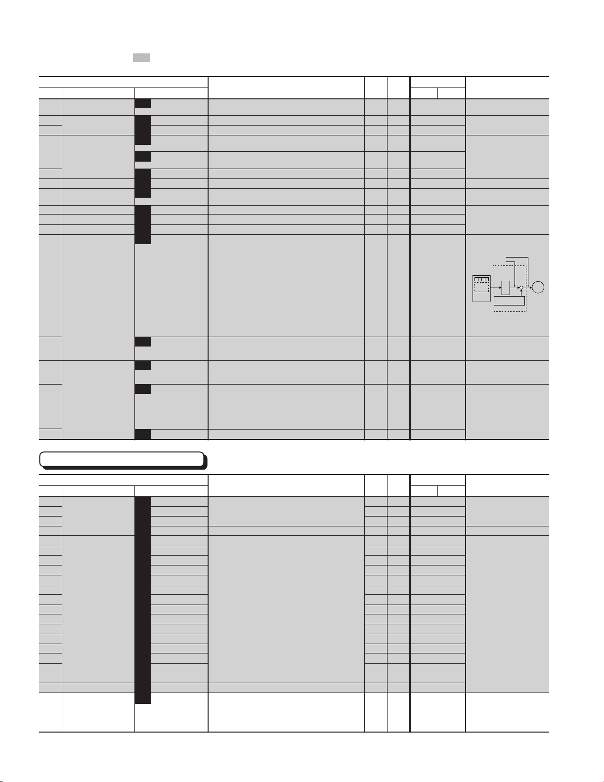
Chapter 1
2. Common Specifications
The function marked can be set while the inverter is running. Other functions must be set while the inverter is
stopped.
Function
Code Name LCD monitor unit 30HP 40HP
E30 FAR function (Hysteresis) E30 FAR HYSTR 0.0 to 10.0 Hz
signal
Setting range Unit
E31 FDT1 function (Level) E31 FDT1 LEVEL G11S : 0 to 400 Hz P11S : 0 to 120 Hz
E32 signal (Hysteresis) E32 FDT HYSTR 0.0 to 30.0 Hz
E33 OL1 function(Mode select) E33 OL1 WARNING 0 : Thermal calculation
signal 1 : Output current
E34 (Level) E34 OL1 LEVEL G11S : Approx. 5 to 200% of rated current
P11S : Approx. 5 to 150% of rated current
E35 (Timer) E35 OL TIMER 0.0 to 60.0s
E36 FDT2 function (Level) E36 FDT2 LEVEL G11S : 0 to 400Hz P11S : 0 to 120Hz
E37 OL2 function (Level) E37 OL2 LEVEL G11S : Approx. 5 to 200% of rated current
P11S : Approx. 5 to 150% of rated current
E40 Display coefficient A E40 COEF A -999.00 to 999.00
E41 Display coefficient B E41 COEF B -999.00 to 999.00
E42 LED Display filter E42 DISPLAY FL 0.0 to 5.0s
E43 LED Monitor (Function) E43 LED MNTR 0 : Output frequency 1 (Before slip compensation)
E44 (Display at STOP mode) E44 LED MNTR2 0 : Setting value
E45 LCD Monitor (Function) E45 LCD MNTR 0 :Displays operation guidance
E46 (Language) E46 LANGUAGE 0 :Japanese
1: Output frequency 2 (After slip compensation)
2: Setting frequency [Hz]
3: Output current [A]
4: Output voltage [V]
5: Motor synchronous speed [r/min]
6: Line speed [m/min]
7: Load shaft speed [r/min]
8: Torque calculation value [%]
9: Input power [kW]
10 : PID reference value
11 : PID reference value (remote)
12 : PID feedback value
[Hz]
1: Output value
1 :Bar graph
(Output freq., Output current, and Output torque)
1 :English
2 :German
3 :French
4 :Spanish
5 :Italian
E47 (Contrast) E47 CONTRAST 0 (Soft) to 10 (Hard)
Min. Factory setting
Hz 0.1 2.5
Hz 1 60
Hz 0.1 1.0
-- 0
A 0.01 Motor rated
current
s 0.1 10.0
Hz 1 60
A 0.01 Motor rated
current
- 0.01 0.01
- 0.01 0.00
s 0.1 0.5
-- 0
-- 0
-- 0
-- 1
-- 5
Remarks
E20 to E24: 1
E20 to E24: 2
E20 to E24: 7
About 0 and 1
1:Output frequency 2
0:Output frequency 1
Setting
value
KEYPAD
panel
Slip compensation
amount
Selects items displayed on
the LED monitor when
inverter is stopping.
Indicates based on inverter
rated current.
M
Inverter
Control Functions of Frequency
Function
Code Name LCD monitor unit 30HP 40HP
Setting range Unit
C01 Jump (Jump freq. 1) C01 JUMP Hz 1 G11S : 0 to 400Hz P11S : 0 to 120Hz
C02 frequency(Jump freq. 2) C02 JUMP Hz 2
C03 (Jump freq. 3) C03 JUMP Hz 3
C04 (Hysteresis) C04 JUMP HYSTR 0 to 30Hz
C05 Multistep (Freq. 1) C05 MULTI Hz-1 G11S : 0.00 to 400.00Hz P11S : 0.00 to 120.00Hz
C06 frequency (Freq. 2) C06 MULTI Hz-2
C07 setting (Freq. 3) C07 MULTI Hz-3
C08 (Freq. 4) C08 MULTI Hz-4
C09 (Freq. 5) C09 MULTI Hz-5
C10 (Freq. 6) C10 MULTI Hz-6
C11 (Freq. 7) C11 MULTI Hz-7
C12 (Freq. 8) C12 MULTI Hz-8
C13 (Freq. 9) C13 MULTI Hz-9
C14 (Freq.10) C14 MULTI Hz10
C15 (Freq.11) C15 MULTI Hz11
C16 (Freq.12) C16 MULTI Hz12
C17 (Freq.13) C17 MULTI Hz13
C18 (Freq.14) C18 MULTI Hz14
C19 (Freq.15) C19 MULTI Hz15
C20 JOG frequency C20 JOG Hz G11S : 0.00 to 400.00Hz P11S : 0.00 to 120.00Hz
C21 PATTERN operation C21 PATTERN 0 : Active (Mono-cycle operation, and then stops.)
(Mode select) 1 : Active (Continuous cyclic operation during
operation command is effective.)
2: Active (Mono-cycle operation, and after
continues at the latest setting frequency.)
Min. Factory setting
Hz 1 0
Hz 1 0
Hz 1 0
Hz 1 3
Hz 0.01 0.00
Hz 0.01 0.00
Hz 0.01 0.00
Hz 0.01 0.00
Hz 0.01 0.00
Hz 0.01 0.00
Hz 0.01 0.00
Hz 0.01 0.00
Hz 0.01 0.00
Hz 0.01 0.00
Hz 0.01 0.00
Hz 0.01 0.00
Hz 0.01 0.00
Hz 0.01 0.00
Hz 0.01 0.00
Hz 0.01 5.00
-- 0
Remarks
1-14
Page 21
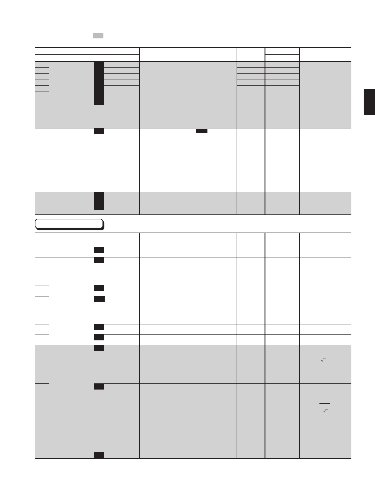
Chapter 1
XM
X2+XM
X1+X2 x +Cable X
V/ ( 3 x I)
%X= x 100
2. Common Specifications
The function marked can be set while the inverter is running. Other functions must be set while the inverter is
stopped.
Function
Code Name LCD monitor unit 30HP 40HP
C22 (Stage 1) C22 STAGE 1 • Operation time: 0.00 to 6000s
C23 (Stage 2) C23 STAGE 2 • F1 to F4 and R1 to R4
C24 (Stage 3) C24 STAGE 3 Code FWD/REV ACC/DEC
C25 (Stage 4) C25 STAGE 4 F1: FWD ACC1 / DEC1
C26 (Stage 5) C26 STAGE 5 F2: FWD ACC2 / DEC2
C27 (Stage 6) C27 STAGE 6 F3: FWD ACC3 / DEC3
C28 (Stage 7) C28 STAGE 7 F4: FWD ACC4 / DEC4
* Setting for R1: REV ACC1 / DEC1
operation time, R2: REV ACC2 / DEC2
FWD/REV rotation and R3: REV ACC3 / DEC3
ACC/DEC time select. R4: REV ACC4 / DEC4
C30 Frequency command 2 C30 FREQ CMD 2 0 : KEYPAD operation (
C31 Offset (Terminal 12) C31 OFFSET 12 -5.0 to +5.0%
C32 Offset (Terminal C1) C32 OFFSET C1 -5.0 to +5.0%
C33 Analog setting signal C33 REF FILTER 0.00 to 5.00s
filter
1: Voltage input (terminal 12) (0 to 10Vdc, 0 to 5Vdc)
2: Current input (terminal C1) (4 to 20mAdc)
3: Voltage and current input (terminals 12 and C1)
4: Reversible operation with polarity (terminal 12)
(0 to ± 10Vdc)
5: Reversible operation with polarity
(terminal 12 and V1) (0 to ± 10Vdc)
6: Inverse mode operation (terminal 12) (10 to 0Vdc)
7: Inverse mode operation (terminal C1) (20 to 4mAdc)
8: UP/DOWN control 1 (initial freq. = 0Hz)
9: UP/DOWN control 2 (initial freq. = last value)
10 : PATTERN operation
11 : DI option or Pulse train input
Setting range Unit
∨
or key)
Min. Factory setting
s 0.01 0.00 F1
s 0.01 0.00 F1
s 0.01 0.00 F1
s 0.01 0.00 F1
s 0.01 0.00 F1
s 0.01 0.00 F1
s 0.01 0.00 F1
-- 2
%0.1 0.0
%0.1 100.0
s 0.01 0.05
Remarks
F01, H30
F17,18
E01-09:11,20,23
Data 2, 3, and 7
are always inactive
E01-E09:21
E01-E09:21
E01-E09:17
E01-E09:18
C21-C28
1
Motor Parameters
Function
Code Name LCD monitor unit 30HP 40HP
P01 Number of motor 1 poles P01 M1 POLES 2 to 14
P02 Motor 1 (Capacity) P02 M1-CAP 30HP or smaller : 0.01 to 45.00 kW
P03 (Rated current) P03 M1-Ir 0.00 to 2000 A
P04 (Tuning) P04 M1 TUN1 0 : Inactive
P05 (On-line Tuning) P05 M1 TUN2 0 : Inactive
P06 (No-load current) P06 M1-Io 0.00 to 2000 A
P07 (%R1 setting) P07 M1-%R1 0.00 to 50.00 %
P08 (%X setting) P08 M1-%X 0.00 to 50.00 %
40HP or larger : 0.01 to 500.00 kW
1: Active (One time tuning of %R1 and %X (on
motor stopping mode ))
2: Active (One time tuning of %R1, %X and Io (on
motor running mode ))
1: Active (Real time tuning of %R2)
Setting range Unit
Min. Factory setting
pole 2 4
kW 0.01 Motor Capacity
A 0.01
-- 0
-- 0
A 0.01 Fuji standard
% 0.01 Fuji standard
% 0.01 Fuji standard
Motor rated
current
rated value
rated value
rated value
Remarks
Sets the number poles of
the motor 1.
Set the applied motor capacity.
This setting automatically sets
"P03" and "P06" to "P08".
Frame must be from -2 to +1.
When a frame is outside this
range, take a special note.
Sets the motor rated current.
Measure %R1 of motor, and
%X and Io at base frequency.
When "1" is selected, data is
stored in "P07" and "P08". When
"2" selected, data is stored in
"P06" to "P08".
Data in "P07" and "P08" is
not updated.
Sets exciting current at
torque-vector control.
Sets motor primary coil
resistance manually.
R1+Cable R
%R1= x 100
V/( 3 x I)
R1: Motor primary resistance [Ω]
Cable R : Resistance at output
side cable
V : Rated voltage [V]
I : Motor rated current [A]
Sets motor leakage
inductance at base
frequency manually.
P09
NOTE: Percent shall be set according to Function code "P02" or "A09", motor capacity.
(Slip compensation control 1)
P09 SLIP COMP1 0.00 to +15.00 Hz
Torque referenced here may not be obtainable when "P02" or "A09" is set at "0".
Hz 0.01 0.00
X1 : Motor primary leakage
reactance [Ω]
X2 : Motor secondary leakage
reacstance [Ω]
XM : Excitation reactance [Ω]
Cable X : Cable resctance
(Primary conversion value) [Ω]
V : Rated voltage [V]
I : Motor rated current [A]
Sets the slip frequency.
1-15
Page 22
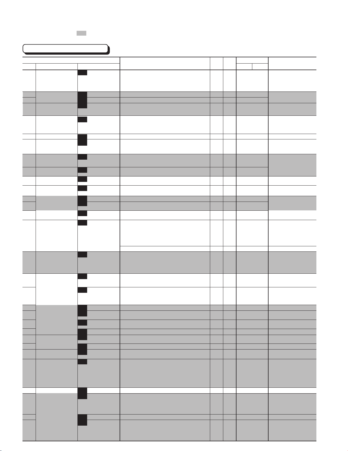
Chapter 1
2. Common Specifications
The function marked can be set while the inverter is running. Other functions must be set while the inverter is
stopped.
High Performance Functions
1-16
Function
Code Name LCD monitor unit 30HP 40HP
H03 Data initializing H03 DATA INIT 0 : Manual set value
H04 Auto-reset (Times) H04 AUTO-RESET 0 (Inactive), 1 to 10 times
H05 (Reset interval) H05 RESET INT 2 to 20s
H06 Fan stop operation H06 FAN STOP 0: Inactive
H07 ACC/DEC (Mode select) H07 ACC PTN 0 : Linear
pattern 1 : S-curve (weak)
H08 Rev. phase sequence lock H08 REV LOCK 0 : Inactive 1 : Active
H09 Start mode H09 START MODE 0 : Inactive
(Rotating motor pick up) 1 :
H10 Energy-saving operation H10 ENERGY SAV 0 : Inactive
H11 DEC mode H11 DEC MODE 0 : Normal (According to "H07" mode)
H12 Instantaneous H12 INST CL 0 : Inactive
overcurrent limiting 1 : Active
H13 Auto-restart (Restart time) H13 RESTART t 0.1 to 10.0s
H14 (Freq. fall rate) H14 FALL RATE 0.00 to 100.00 Hz/s
H15 (Holding DC voltage) H15 HOLD V 200 to 300V (230V)
(OPR command selfhold time)
H16
H18 Torque control H18 TRQ CTRL G11S 0 : Inactive (Frequency control)
H19 Active drive H19 AUT RED 0 : Inactive
H20 PID control (Mode select) H20 PID MODE 0 : Inactive
H21 (Feedback signal) H21 FB SIGNAL 0 : Terminal 12 (0 to +10V)
H22 (P-gain) H22 P-GAIN 0.01 to 10.00
H23 (I-gain) H23 I-GAIN 0.0 : Inactive
H24 (D-gain) H24 D-GAIN 0.00 : Inactive
H25 (Feedback filter) H25 FB FILTER 0.0 to 60.0s
PTC thermistor (Mode select)
H26
H27 (Level) H27 PTC LEVEL 0.00 to 5.00V
H28 Droop operation H28 DROOP G11S: -9.9 to 0.0Hz
H30 Serial link(Function select) H30 LINK FUNC (Code) (Monitor) (Frequency (Operation
H31 RS-485 (Address) H31 485ADDRESS 1 to 31
H32 (Mode select on no H32 MODE ON ER 0 : Trip and alarm (Er8)
H33 (Timer) H33 TIMER 0.0 to 60.0s
H34 (Baud rate) H34 BAUD RATE 0 : 19200 bit/s
(Data reset) 1 : Return to factory set value
1: Active (Fan stops at low temperature mode (2HP
or larger)
2: S-curve (strong)
4: Non-linear (For variable torque load)
Active (Only Auto-restart after momentary power failure mode )
2: Active (All start mode)
1: Active (Only when torque boost "F09" is in
manual setting mode
1: Coast-to-stop
H16 SELFHOLD t 0.0 to 30.0s, 999s (999s: The operation command is
H26 PTC MODE 0 : Inactive
response error) 1 : Operation for H33 timer, and alarm (Er8)
400 to 600V (460V)
held during DC link circuit voltage is larger than 50V)
1: Active (Torque control by terminal 12 (Driving))
2: Active (Torque control by terminal 12 (Driving &
P11S 0 : Inactive (Fixed)
1: Active
1: Active
2: Active (inverse operation mode)
1: Ter minal C1 (4 to 20mA)
2: Ter minal 12 (+10 to 0V)
3: Ter minal C1 (20 to 4mA)
0.1 to 3600.0s
0.01 to 10.0s
1: Active
P11S : 0.0 (Fixed)
0 : X - 1: X X 2 : X - X
3 : X X X
2: Operation for H33 timer,and retry to communicate.
* If the retry fails, then the inverter trips("Er 8").
3: Continuous operation
1: 9600
2: 4800
3: 2400
4: 1200
Setting range Unit
(0 to +10V/0 to 200%)
Braking))
(0 to +10V/0 to 200%)
command) command)
(X: Valid -: Invalid)
Min. Factory setting
-- 0
-1 0
s1 5
-- 0
-- 0
-- 0
-- 0
-- G11S:0
-- 0
-- 1
s0.1 0.5
Hz/s 0.01 10.00
V 1 230V class : 235V
s0.1 999
-- 0
-- 0
-- 0
-- 0
-- 1
- 0.01 0.1
s 0.1 0.0
s 0.01 0.00
s 0.1 0.5
-- 0
V 0.01 1.60
Hz 0.1 0.0
-- 0
-1 1
-- 0
s 0.1 2.0
-- 1
P11S:1
460V class : 470V
Remarks
When data code is set at "1", all
function data is returned to
initial data (factory setting data).
Automatically returns to "0"
after initializing.
Time required until motor residual
voltage reduces to zero.
P11S series does not have
this function.
Gain for frequency setting
is disabled.
When the acceleration time is
longer than 60s, this function
prevents inverter trip due to
overvurrent, to accelerates
motor in a shortest time.
E01-E09:20
C33
E01-E09:21
P11S does not have this
function.
Selects type of LINK
operation in LINK operation
mode.
F01:11, C30:11,
E01-E09:24,25, F02
Page 23
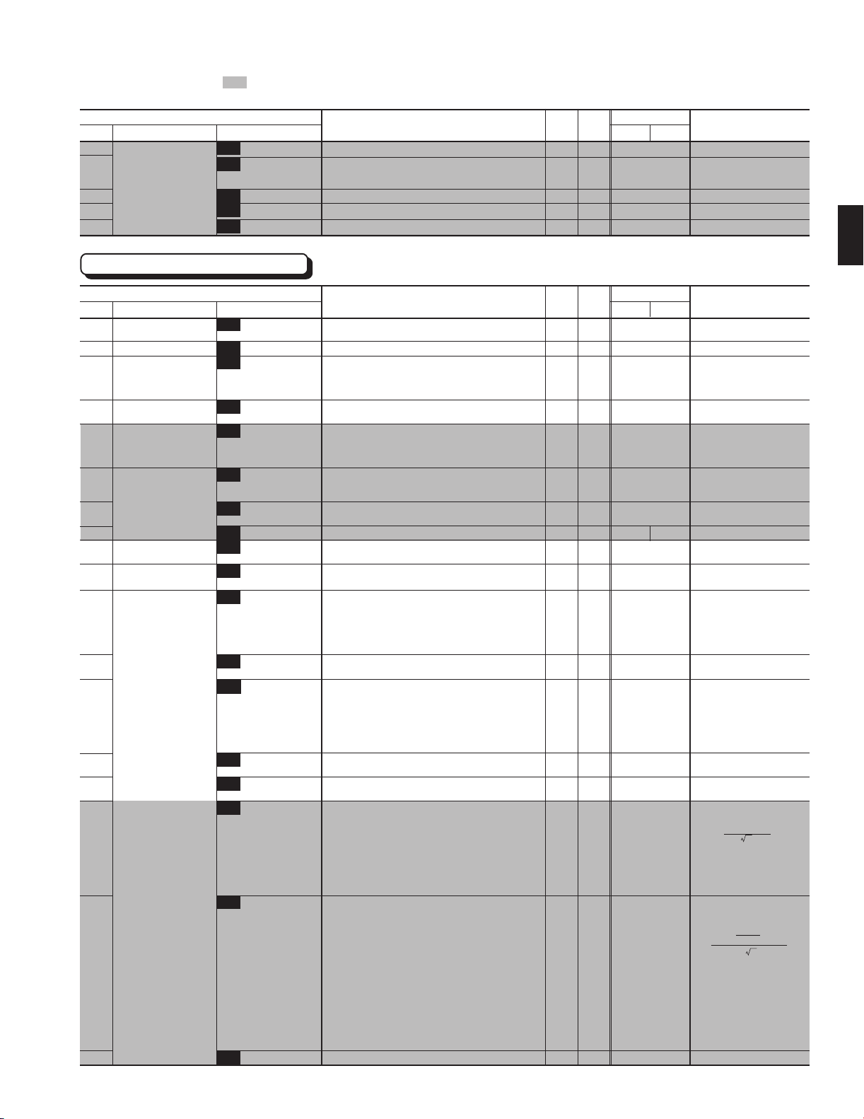
Chapter 1
2. Common Specifications
The function marked can be set while the inverter is running. Other functions must be set while the inverter is
stopped.
Function
Code Name LCD monitor unit 30HP 40HP
H35 (Data length) H35 LENGTH 0 : 8 bit 1 : 7 bit
H36 (Parity check) H36 PARITY 0 : No checking
H37 (Stop bits) H37 STOP BITS 0 : 2 bit 1 : 1 bit
H38
H39 (Response interval) H39 INTERVAL 0.00 to 1.00s
(No response error
detection time)
H38 NO RES t 0 (No detection), 1 to 60s
1: Even parity
2: Odd parity
Setting range Unit
Alternative Motor Parameters
Min. Factory setting
-- 0
-- 0
-- 0
s1 0
s 0.01 0.01
Remarks
1
Function
Code Name LCD monitor unit 30HP 40HP
A01 Maximum frequency 2 A01 MAX Hz-2 G11S : 50 to 400Hz P11S : 50 to 120Hz
A02 Base frequency 2 A02 BASE Hz-2 G11S : 25 to 400Hz P11S : 25 to 120Hz
A03 Rated voltage 2 A03 RATED V-2 0V (Free) : The output voltage in proporpion to the
80 to 240V : AVR active (230V)
320 to 480V : AVR active (460V)
A04 Maximum voltage 2 A04 MAX V-2 80 to 240V : AVR active (230V)
(at Maximum frequency 2) 320 to 480V : AVR active (460V)
A05 Torque boost 2 A05 TRQ BOOST2 0.0 : Automatic (for constant torque load)
A06 Electronic (Select) A06 ELCTRN OL2 0 : Inactive
thermal 1 : Active (for 4-pole standard motor)
overload relay 2 : Active (for 4-pole inverter motor)
A07 for motor 2 (Level) A07 OL LEVEL2 Approx. 20 to 135% of the inverter rated current, in
A08 (Thermal time constant) A08 TIME CNST2 0.5 to 75.0 min
A09 Torque vector control 2 A09 TRQVECTOR2 0 : Inactive
A10 Number of motor-2 poles A10 M2 POLES 2 to 14
A11 Motor 2 (Capacity) A11 M2-CAP 30HP or smaller : 0.01 to 45.00 kW
A12 (Rated current) A12 M2-Ir 0.00 to 2000 A
A13 (Tuning) A13 M2 TUN1 0 : Inactive
A14 (On-line Tuning) A14 M2 TUN2 0 : Inactive
A15 (No-load current) A15 M2-Io 0.00 to 2000 A
A16 (%R1 setting) A16 M2-%R1 0.00 to 50.00 %
A17 (%X setting) A17 M2-%X 0.00 to 50.00 %
(Slip compensation control 2)
A18
A18 SLIP COMP2 0.00 to +15.00 Hz
0.1 to 0.9 : Manual (for variable torque load)
1.0 to 1.9 : Manual (for proportional torque load)
2.0 to 20.0 : Manual (for constant torque load)
Ampere
1: Active
40HP or larger : 0.01 to 500.00 kW
1: Active (One time tuning of %R1 and %X (on
motor stopping mode ))
2: Active (One time tuning of %R1, %X and Io (on
motor running mode ))
1: Active (Real time tuning of %R1 and %X)
Setting range Unit
power supply voltage is set.(at Base frequency 2)
Min. Factory setting
Hz 1 60
Hz 1 60
V 1
220:(230V class)
380:(460V class)
V 1220:(230V class)
- 0.1 G11S : 2.0
-- 1
A 0.01 Motor rated
min 0.1 5.0 10.0
-- 0
- 24
kw 0.01 Motor Capacity
A 0.01 Motor rated
-- 0
-- 0
A 0.01 Fuji standard
% 0.01 Fuji standard
% 0.01 Fuji standard
Hz 0.01 0.00
380:(460V class)
P11S : 2.0
current
current
rated value
rated value
rated value
Remarks
Sets the maximum output
frequency for motor 2.
Sets the output voltage at
the Base frequency 2 "A02".
Sets the output voltage at the
Maximum frequency 2 "A01".
Sets the number of poles of
motor 2.
Set the applied motor capacity.
This setting automatically sets
"P03" and "P06" to "P08". Frame
must be from -2 to +1. When a
frame is outside this range, take
a special note.
Sets the motor rated current.
Measure %R1 of motor, and
%X and Io at base
frequency.
When "1" is selected, data
is stored in "A16" and "A17".
When "2" selected, data is
stored in "A15" to "A17".
Data in "A16" and "A17" is
not updated.
Sets exciting current at
torque-vector control.
Sets motor primary coil
resistance manually.
R1+Cable R
%R1= x 100
V/( 3 x I)
R1: Motor primary resistance [Ω]
Cable R : Resistance at output
side cable
V : Rated voltage [V]
I : Motor rated current [A]
Sets motor leakage
inductance at base
frequency manually.
%X= x 100
X1 : Motor primary leakage
reactance [Ω]
X2 : Motor secondary leakage
reactance [Ω]
XM : Excitation reactance [Ω]
Cable X : Cable resctance
(Primary conversion value) [Ω]
V : Rated voltage [V]
I : Motor rated current [A]
Sets the slip frequency.
XM
X1+X2 x +Cable X
X2+XM
V/ ( 3 x I)
1-17
Page 24
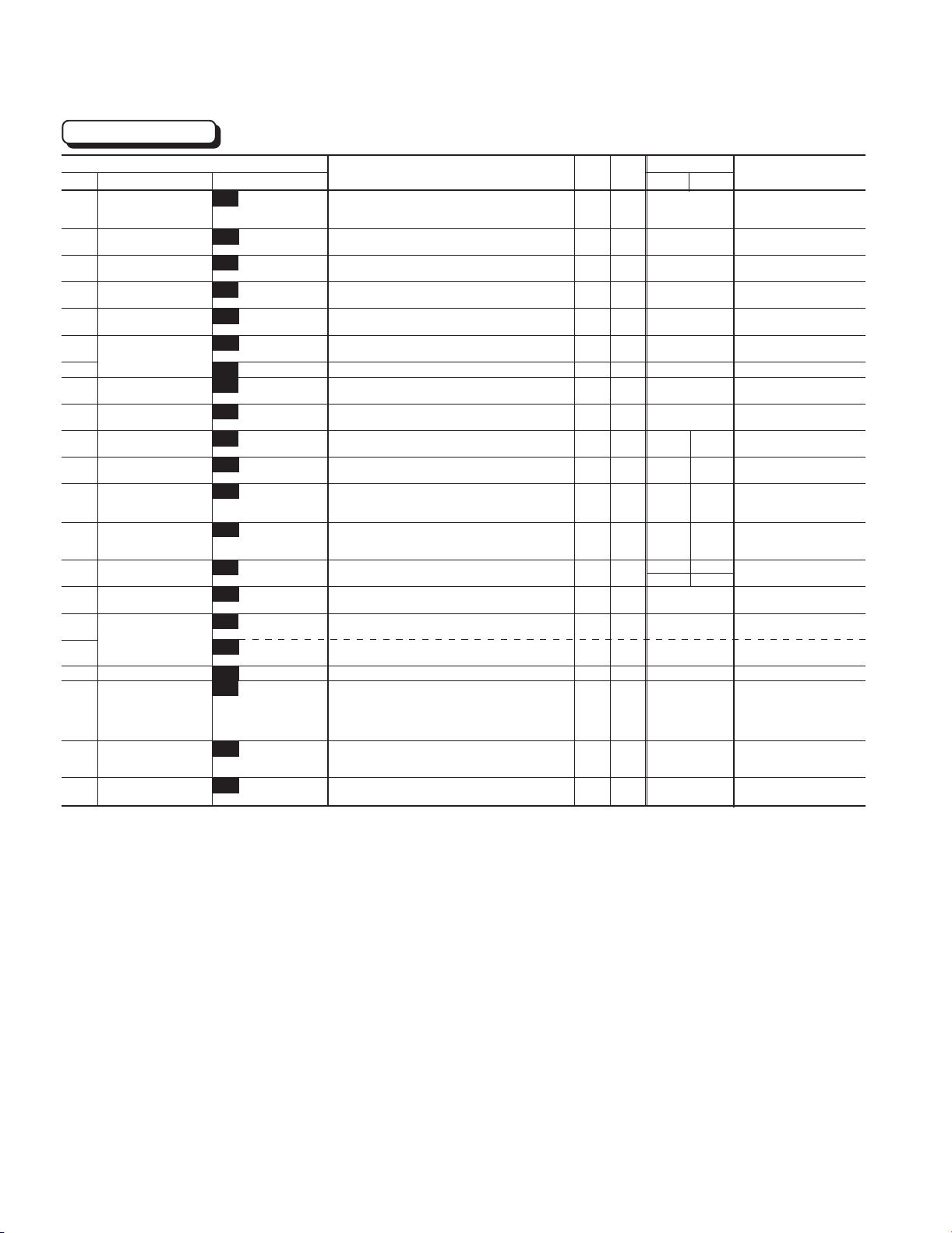
Chapter 1
2. Common Specifications
User Functions
Function
Code Name LCD monitor unit 30HP 40HP
U01 Maximum compensation
frequency during
braking torque limit
U02 1st S-shape level at
acceleration
U03 2nd S-shape level at
acceleration
U04 1st S-shape level at
deceleration
U05 2nd S-shape level at
deceleration
U08 Main DC link capacitor
U09 (Measured value)
U10 PC board capacitor
powered on time
U11 Cooling fan operating
time
U13 Magnetize current
vibration damping gain
U15 Slip compensation filter
time constant
U23 Integral gain of
continuous operation
at power failure
U24 Proportional gain of
continuous operation at
power failure
U48 Input phase loss
protection
U49 RS-485 protocol
selection
U56 Speed agreement
U57 /PG error
U58 PG error selection
U59 Braking-resistor
function select
(up to 30HP)
Manufacturer’s
function (40HP or more)
U60 Regeneration
avoidance at
deceleration
U61 Voltage detect offset
and gain adjustment
(Initial value)
(Detection width)
(Detection timer)
U01 USER 01 0 to 65535 - 1
U02 USER 02 1 to 50% % 1
U03 USER 03 1 to 50% % 1
U04 USER 04 1 to 50% % 1
U05 USER 05 1 to 50% % 1
U08 USER 08 0 to 65535 - 1
U09 USER 09 0 to 65535 - 1
U10 USER 10 0 to 65535h h 1
U11 USER 11 0 to 65535h h 1
U13 USER 13 0 to 32767 - 1
U15 USER 15 0 to 32767 - 1
U23 USER 23 0 to 65535 - 1
U24 USER 24 0 to 65535 - 1
U48 USER 48 0, 1, 2 - -
U49 USER 49 0, 1 - -
U56 USER 56 0 to 50% % 1
U57 USER 57 0.0 to 10.0s s 0.1
U58 USER 58 0, 1 - -
U59 USER 59 00 to A8(HEX) - 1
U60 USER 60 0, 1 - -
U61 USER 61 Up to 30HP : F0(Fixed.) - -
40HP or more : F0, 1, 2
Setting range Unit
Min. Factory setting
75
10
10
10
10
xxxx
0
0
0
819 410
556 546
1738 1000
1024 1000
-75HP 100HP0 1
0
10
0.5
1
00
0
0
Remarks
1-18
Page 25
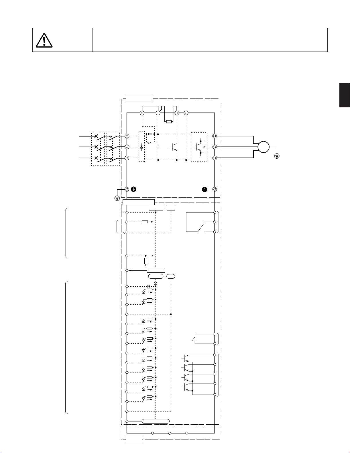
The information described in this document is for the purpose of selecting the
Caution
appropriate product only. Before actually using this product, be sure to read the
Instruction Manual carefully to ensure proper operation.
3. Wiring Diagram
3.1 Wiring diagram before shipment from factory (1) 230V/460V FRENIC5000G11S: 1/4 to 1HP / 1/2, 1HP
Chapter 1
3. Wiring Diagram
Power supply ( *1)
3-phase
200 to 230V
50/60Hz
or
3-phase
400 to 480V
50/60Hz
Potentiometer power supply
Analog input
Analog output (analog monitor)
MCCB
or
GFCI
(*2)
Grounding
Voltage input
Current input
MC
(*2)
Main circuit
Jumper wire (*3)
P1
L1/R
L2/S
L3/T
SR
73
G
Control circuit
[13]
[12]
[11]
[C1]
[FMA]
(PLC)
(FWD)
(REV)
+0〜10Vdc
P(+)
+10Vdc
+24Vdc
DBR
0V
0V
DB
N(-)
30
U
V
W
( *4)
G
30C
30B
Alarm output (for any fault)
30A
NOTE: Common terminals [11], (CM), and <CME> for
control circuits are isolated from one another.
(*1) Use the inverter whose rated input voltage
matches the power supply voltage.
(*2) Use this peripheral device when necessary.
(*3) Terminals [P1] and [P(+)] are connected
with a jumper wire before shipping.
(*4) Terminal for grounding the motor.
Connect it, if necessary.
1
Motor
M
G
Digital input
Pulse output
(frequency monitor)
(CM)
(X1)
(X2)
(X3)
(X4)
(X5)
(X6)
(X7)
(X8)
(X9)
(CM)
(FMP)
RS-485
Pulse output
(DX-)
(DX+)
(SD)
<Y5C>
<Y5A>
<Y4>
<Y3>
<Y2>
<Y1>
<CME>
Relay output
Transistor output
1-19
Page 26
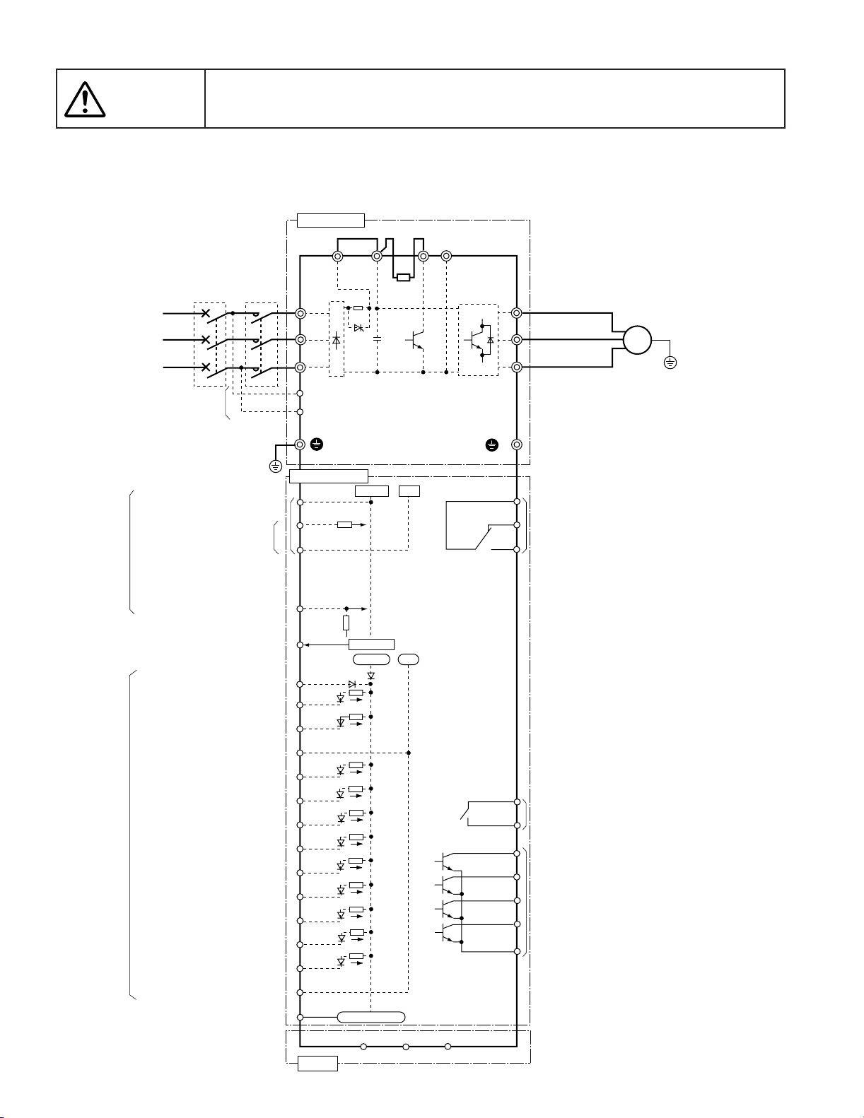
Chapter 1
3. Wiring Diagram
The information described in this document is for the purpose of selecting the
Caution
(2) 230V/460V FRENIC5000G11S : 2 to 10HP
appropriate product only. Before actually using this product, be sure to read the
Instruction Manual carefully to ensure proper operation.
FRENIC5000P11S : 7.5 to 15HP
Main circuit
Jumper wire (*3)
Power supply ( *1)
3-phase
200 to 230V
50/60Hz
or
3-phase
400 to 480V
50/60Hz
Potentiometer power supply
Analog input
Analog output (analog monitor)
Digital input
MCCB
or
GFCI
(*2)
Auxiliary control
power supply (*4)
Grounding
Voltage input
Current input
Pulse output
(frequency monitor)
MC
(*2)
P1
L1/R
L2/S
L3/T
(R0)
(T0)
SR
G
Control circuit
[13]
[12]
[11]
[C1]
[FMA]
(PLC)
(FWD)
(REV)
(CM)
(X1)
(X2)
(X3)
(X4)
(X5)
(X6)
(X7)
(X8)
(X9)
(CM)
(FMP)
+0 〜10Vdc
Pulse output
P(+)
+10Vdc
+24Vdc
(DX-)
DBR
(*5)
0V
0V
(DX+)
DB
(SD)
N(-)
30
W
G
30C
30B
30A
<Y5C>
<Y5A>
<Y4>
<Y3>
<Y2>
<Y1>
<CME>
U
V
(*6)
Alarm output (for any fault)
NOTE: Common terminals [11], (CM), and <CME> for
control circuits are isolated from one another.
(*1) Use the inverter whose rated input voltage
matches the power supply voltage.
(*2) Use this peripheral device when necessary.
(*3) Terminals [P1] and [P(+)] are connected
with a jumper wire before shipping.
(*4) Even if these terminals are not powered,
the inverter can be operated.
(*5) The built-in braking resistor (DBR) is not
mounted on P11S models 7.5HP to 15HP
(*6) Terminal for grounding the motor.
Connect it, if necessary.
Relay output
Transistor output
Motor
M
G
1-20
RS-485
Page 27
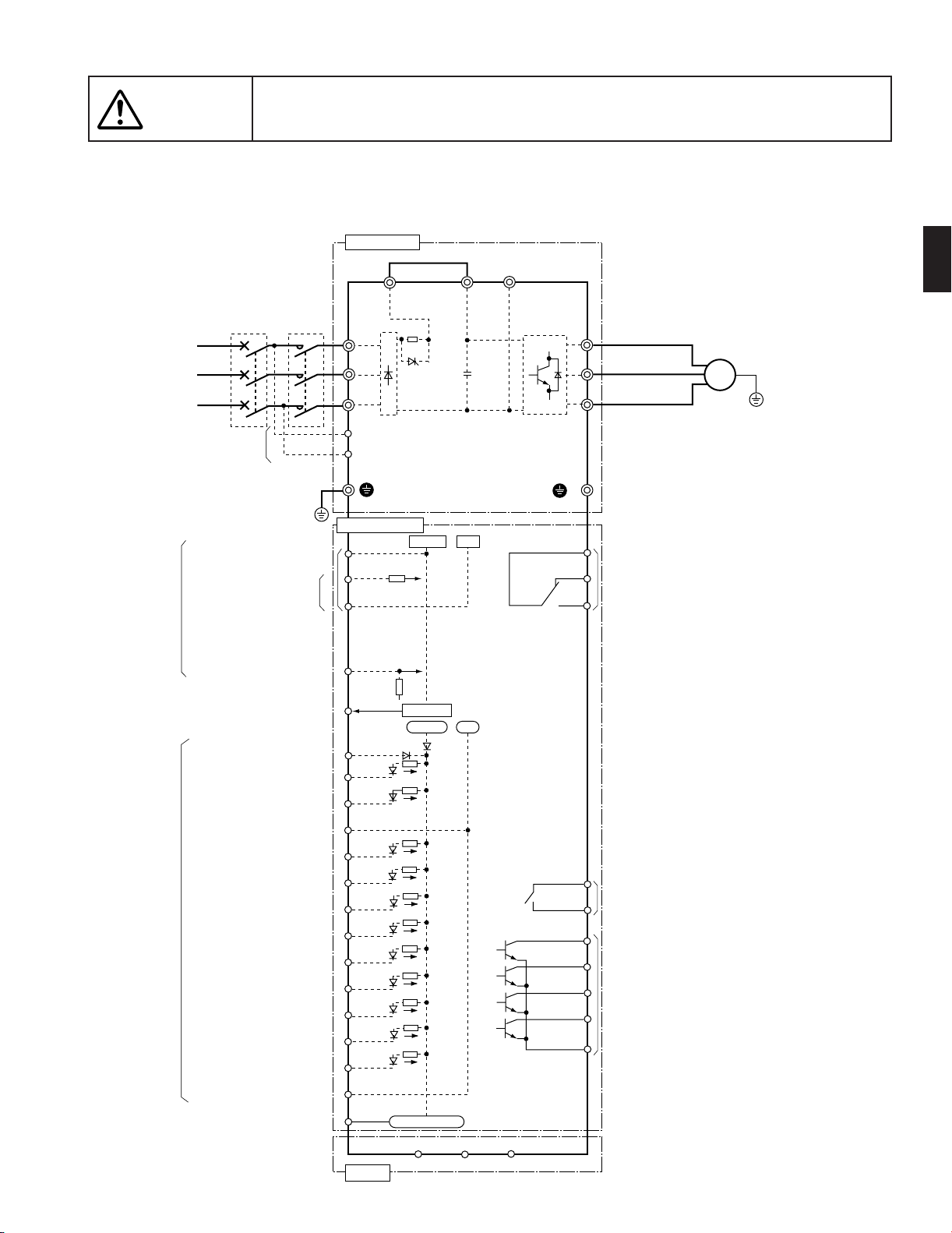
The information described in this document is for the purpose of selecting the
Caution
appropriate product only. Before actually using this product, be sure to read the
Instruction Manual carefully to ensure proper operation.
(3) 230V/460V FRENIC5000G11S : 15 to 30HP
FRENIC5000P11S : 20 to 30HP
Main circuit
Jumper wire (*3)
Chapter 1
3. Wiring Diagram
1
Power supply ( *1)
3-phase
200 to 230V
50/60Hz
or
3-phase
400 to 480V
50/60Hz
Analog input
Digital input
Auxiliary control
power supply (*4)
Potentiometer power supply
Analog output (analog monitor)
MCCB
or
GFCI
(*2)
Pulse output
(frequency monitor)
MC
(*2)
Grounding
Voltage input
Current input
P1
L1/R
L2/S
L3/T
(R0)
(T0)
SR
G
Control circuit
[13]
[12]
[11]
[C1]
[FMA]
(PLC)
(FWD)
(REV)
(CM)
(X1)
(X2)
(X3)
(X4)
(X5)
(X6)
(X7)
(X8)
(X9)
(CM)
(FMP)
+0〜10Vdc
Pulse output
(DX-)
+10Vdc
+24Vdc
0V
0V
(DX+)
P(+)
(SD)
N(-)
30
U
V
W
G
30C
30B
30A
<Y5C>
<Y5A>
<Y4>
<Y3>
<Y2>
<Y1>
<CME>
Motor
M
G
(*5)
Alarm output (for any fault)
NOTE: Common terminals [11], (CM), and <CME> for
control circuits are isolated from one another.
(*1) Use the inverter whose rated input voltage
matches the power supply voltage.
(*2) Use this peripheral device when necessary.
(*3) Terminals [P1] and [P(+)] are connected
with a jumper wire before shipping.
(*4) Even if these terminals are not powered,
the inverter can be operated.
(*5) Terminal for grounding the motor.
Connect it, if necessary.
Relay output
Transistor output
RS-485
1-21
Page 28
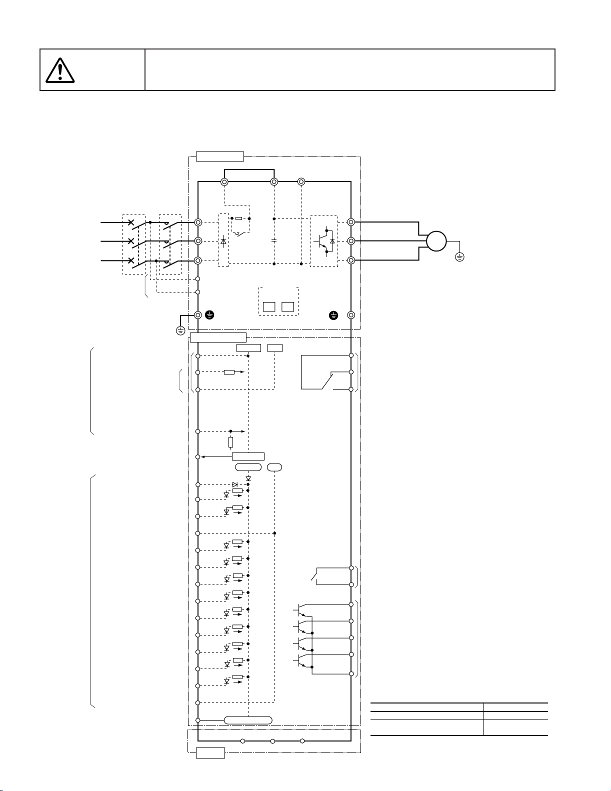
Chapter 1
3. Wiring Diagram
The information described in this document is for the purpose of selecting the
Caution
(4) 230V/460V FRENIC5000G11S : 40 to 75HP
appropriate product only. Before actually using this product, be sure to read the
Instruction Manual carefully to ensure proper operation.
FRENIC5000P11S : 40 to 75HP
Main circuit
Jumper wire (*3)
Power supply ( *1)
3-phase
200 to 230V
50/60Hz
or
3-phase
400 to 480V
50/60Hz
Analog input
Digital input
Auxiliary control
power supply (*4)
Potentiometer power supply
Analog output (analog monitor)
MCCB
or
GFCI
(*2)
Pulse output
(frequency monitor)
MC
(*2)
Grounding
Voltage input
Current input
P1
L1/R
L2/S
L3/T
(R0)
(T0)
G
Control circuit
[13]
[12]
[11]
[C1]
[FMA]
(PLC)
(FWD)
(REV)
(CM)
(X1)
(X2)
(X3)
(X4)
(X5)
(X6)
(X7)
(X8)
(X9)
(CM)
(FMP)
Pulse output
SR
73
+10Vdc
+0〜10Vdc
+24Vdc
(DX-)
P(+)
CNUX (∗)
U1 U2
0V
0V
(DX+)
(SD)
N(-)
30
U
V
W
G
30C
30B
30A
<Y5C>
<Y5A>
<Y4>
<Y3>
<Y2>
<Y1>
<CME>
Motor
M
G
(*5)
Alarm output (for any fault)
NOTE: Common terminals [11], (CM), and <CME> for
control circuits are isolated from one another.
(*1) Use the inverter whose rated input voltage
matches the power supply voltage.
(*2) Use this peripheral device when necessary.
(*3) Terminals [P1] and [P(+)] are connected
with a jumper wire before shipping.
(*4) Even if these terminals are not powered,
the inverter can be operated.
(*5) Terminal for grounding the motor.
Connect it, if necessary.
Relay output
Transistor output
(∗)
400 to 440V/50Hz, 440 to 480V/60Hz
380V/50Hz (398V or smaller),
380 to 415V/60Hz (430V or smaller)
Input voltage
CNUX connector
U1
U2
1-22
RS-485
Page 29
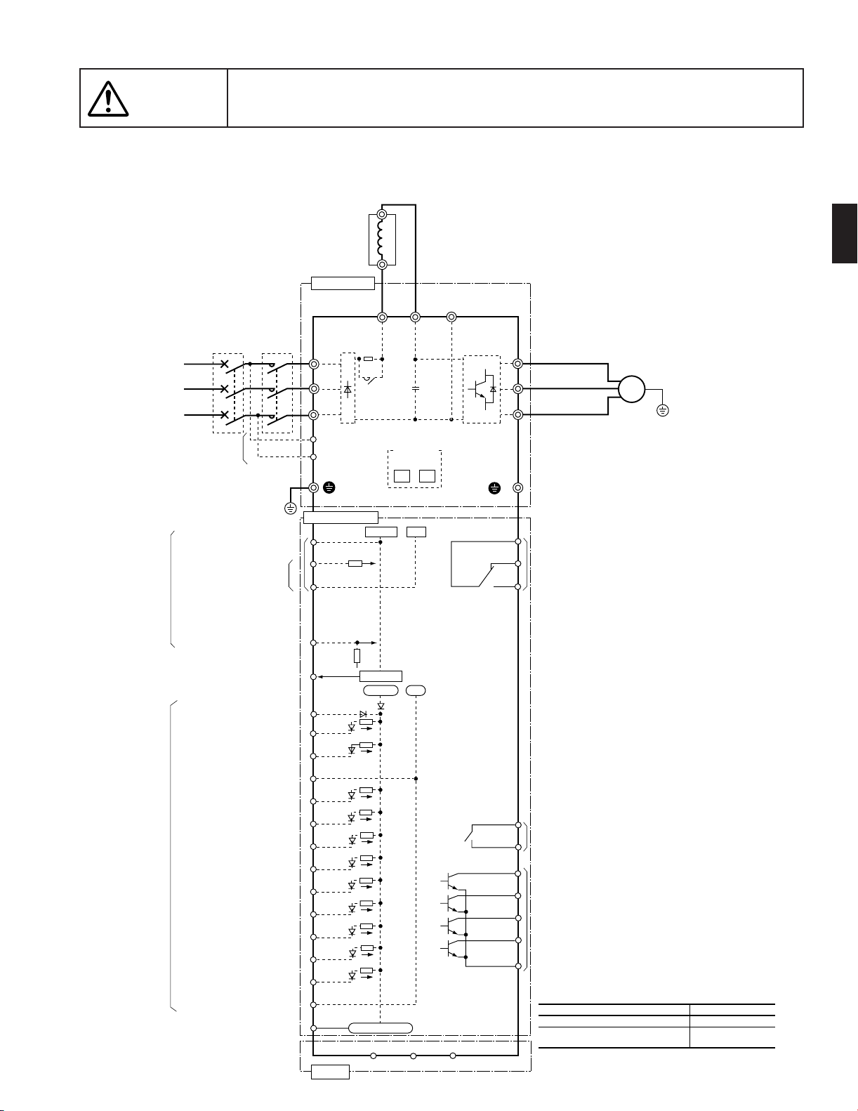
The information described in this document is for the purpose of selecting the
Caution
appropriate product only. Before actually using this product, be sure to read the
Instruction Manual carefully to ensure proper operation.
(5) 2300V/460V FRENIC5000G11S : 100, 125HP / 100 to 600HP
FRENIC5000P11S : 100 to 150HP / 100 to 800HP
DC REACTOR (DCR)
(*3)
Main circuit
MCCB
Power supply ( *1)
3-phase
200 to 230V
50/60Hz
or
3-phase
400 to 480V
50/60Hz
Auxiliary control
power supply (*4)
or
GFCI
(*2)
Grounding
MC
(*2)
L1/R
L2/S
L3/T
(R0)
(T0)
N(-)
P1
SR
73
G
P(+)
CNUX (∗)
U1 U2
Chapter 1
3. Wiring Diagram
1
U
V
W
(*5)
G
Motor
M
G
Analog input
Digital input
Potentiometer power supply
Voltage input
Current input
Analog output (analog monitor)
Pulse output
(frequency monitor)
Control circuit
[13]
[12]
[11]
[C1]
[FMA]
(PLC)
(FWD)
(REV)
(CM)
(X2)
(X3)
(X4)
(X5)
(X6)
(X7)
(X8)
(X1)
(X9)
(CM)
(FMP)
+0〜10Vdc
Pulse output
+10Vdc
+24Vdc
(DX-)
0V
0V
(DX+)
(SD)
30
30C
30B
30A
<Y5C>
<Y5A>
<Y4>
<Y3>
<Y2>
<Y1>
<CME>
Alarm output (for any fault)
NOTE: Common terminals [11], (CM), and <CME> for
control circuits are isolated from one another.
(*1) Use the inverter whose rated input voltage
matches the power supply voltage.
(*2) Use this peripheral device when necessary.
(*3) A DC REACTOR (DCR) is provided as standard in
JE version for inverters of 100HP or larger
(separately installed).
Be sure to connect the DCR properly.
(*4) Even if these terminals are not powered,
the inverter can be operated.
(*5) Terminal for grounding the motor.
Connect it, if necessary.
Relay output
Transistor output
(∗)
400 to 440V/50Hz, 440 to 480V/60Hz
380V/50Hz (398V or smaller),
380 to 415V/60Hz (430V or smaller)
Input voltage
CNUX connector
U1
U2
RS-485
1-23
Page 30
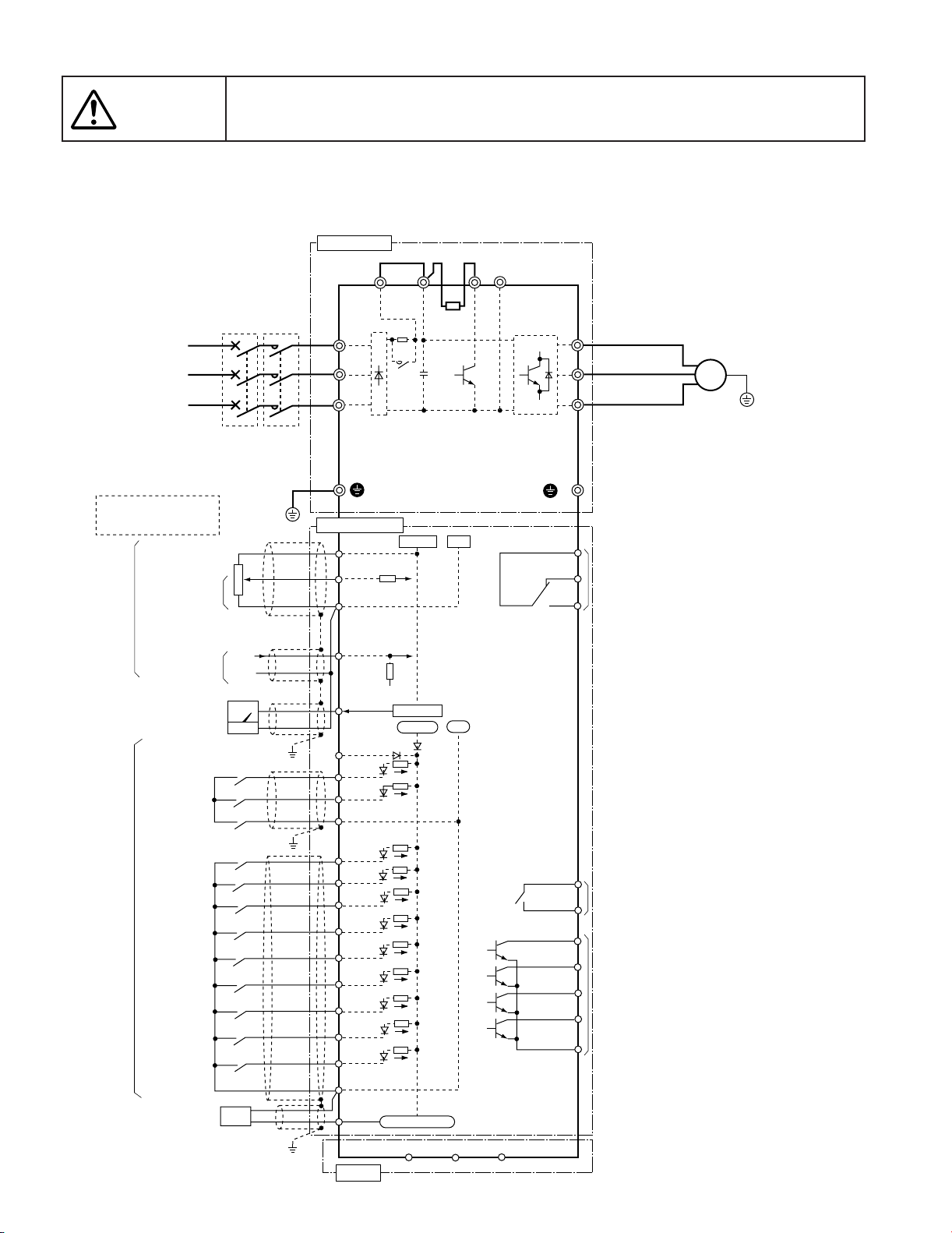
Chapter 1
3. Wiring Diagram
The information described in this document is for the purpose of selecting the
Caution
3.2 Basic wiring diagram (1) 230V/460V FRENIC5000G11S : 1/4 to 1HP / 1/2, 1HP
appropriate product only. Before actually using this product, be sure to read the
Instruction Manual carefully to ensure proper operation.
Power supply ( *1)
3-phase
200 to 230V
50/60Hz
or
3-phase
400 to 480V
50/60Hz
It is possible to input voltage
signals (0 to +10Vdc or 0 to
+5Vdc) to terminals [12]-[11]
instead of the potentiometer.
Analog input
Analog frequency meter
Potentiometer
power supply (*2)
Voltage input
0 to 10Vdc
Current input
4 to 20mAdc
0 to 60Hz
FM (*2)
MCCB
or
GFCI
(*3)
Grounding
3
2
1
(+)
(–)
MC
(*3)
Main circuit
Jumper wire (*4)
P1
L1/R
L2/S
L3/T
G
Control circuit
[13]
[12]
[11]
[C1]
[FMA]
(PLC)
(FWD)
(REV)
(CM)
P(+)
SR
73
+10Vdc
+0〜10Vdc.
+24Vdc
DBR
0V
0V
DB
N(-)
30
U
V
W
(*5)
G
30C
30B
Alarm output (for any fault)
30A
NOTE: Common terminals [11], (CM), and <CME> for
control circuits are isolated from one another.
(*1) Use the inverter whose rated input voltage
matches the power supply voltage.
(*2) Use this optional device when necessary.
(*3) Use this peripheral device when necessary.
(*4) Terminals [P1] and [P(+)] are connected
with a jumper wire before shipping.
(*5) Terminal for grounding the motor.
Connect it, if necessary.
Motor
M
G
1-24
Digital input
Digital frequency meter
(pulse counter) (*2)
60Hz
(X1)
(X2)
(X3)
(X4)
(X5)
(X6)
(X7)
(X8)
(X9)
(CM)
(FMP)
RS-485
Pulse output
(DX-)
(DX+)
(SD)
<Y5C>
<Y5A>
<Y4>
<Y3>
<Y2>
<Y1>
<CME>
Relay output
Transistor output
Page 31

The information described in this document is for the purpose of selecting the
Caution
appropriate product only. Before actually using this product, be sure to read the
Instruction Manual carefully to ensure proper operation.
(2) 230V/460V FRENIC5000G11S : 2 to 10HP
FRENIC5000P11S : 7.5 to 15HP
Chapter 1
3. Wiring Diagram
Power supply ( *1)
3-phase
200 to 230V
50/60Hz
or
3-phase
400 to 480V
50/60Hz
It is possible to input voltage
signals (0 to +10Vdc or 0 to
+5Vdc) to terminals [12]-[11]
instead of the potentiometer.
Analog input
Analog frequency meter
Digital input
MCCB
or
GFCI
Auxiliary control
power supply (*5)
Potentiometer
power supply (*2)
Voltage input
0 to 10Vdc
Current input
4 to 20mAdc
0 to 60Hz
FM (*2)
(*3)
Grounding
3
2
1
(+)
(–)
MC
(*3)
Main circuit
Jumper wire (*4)
P1
L1/R
L2/S
L3/T
(R0)
(T0)
G
Control circuit
[13]
[12]
[11]
[C1]
[FMA]
(PLC)
(FWD)
(REV)
(CM)
(X1)
(X2)
(X3)
(X4)
(X5)
(X6)
(X7)
(X8)
(X9)
P(+)
SR
+10Vdc
+0〜10Vdc
+24Vdc
DBR
(*6)
0V
0V
DB
N(-)
30
W
G
30C
30B
30A
<Y5C>
<Y5A>
<Y4>
<Y3>
<Y2>
<Y1>
<CME>
U
V
(*7)
Alarm output (for any fault)
NOTE: Common terminals [11], (CM), and <CME> for
control circuits are isolated from one another.
(*1) Use the inverter whose rated input voltage
matches the power supply voltage.
(*2) Use this optional device when necessary.
(*3) Use this peripheral device when necessary.
(*4) Terminals [P1] and [P(+)] are connected
with a jumper wire before shipping.
(*5) Even if these terminals are not powered,
the inverter can be operated.
(*6) The built-in braking resistor (DBR) is not
mounted on P11S models 7.5HP to 15HP.
(*7) Terminal for grounding the motor.
Connect it, if necessary.
Relay output
Transistor output
Motor
M
G
1
Digital frequency meter
(pulse counter) (*2)
60Hz
(CM)
(FMP)
RS-485
Pulse output
(DX-)
(DX+)
(SD)
1-25
Page 32

Chapter 1
3. Wiring Diagram
The information described in this document is for the purpose of selecting the
Caution
(3) 230V/460V FRENIC5000G11S : 15 to 30HP
appropriate product only. Before actually using this product, be sure to read the
Instruction Manual carefully to ensure proper operation.
FRENIC5000P11S : 20 to 30HP
Power supply ( *1)
3-phase
200 to 230V
50/60Hz
or
3-phase
400 to 480V
50/60Hz
It is possible to input voltage
signals (0 to +10Vdc or 0 to
+5Vdc) to terminals [12]-[11]
instead of the potentiometer.
Analog input
Analog frequency meter
MCCB
or
GFCI
Auxiliary control
power supply (*5)
Potentiometer
power supply (*2)
Voltage input
0 to 10Vdc
Current input
4 to 20mAdc
0 to 60Hz
FM (*2)
(*3)
Grounding
3
2
1
(+)
(–)
MC
(*3)
Main circuit
Jumper wire (*4)
P1
L1/R
L2/S
L3/T
(R0)
(T0)
G
Control circuit
[13]
[12]
[11]
[C1]
[FMA]
(PLC)
(FWD)
(REV)
(CM)
SR
+10Vdc
+0〜10Vdc
+24Vdc
0V
0V
P(+)
N(-)
30
U
V
W
(*6)
G
30C
30B
Alarm output (for any fault)
30A
NOTE: Common terminals [11], (CM), and <CME> for
control circuits are isolated from one another.
(*1) Use the inverter whose rated input voltage
matches the power supply voltage.
(*2) Use this optional device when necessary.
(*3) Use this peripheral device when necessary.
(*4) Terminals [P1] and [P(+)] are connected
with a jumper wire before shipping.
(*5) Even if these terminals are not powered,
the inverter can be operated.
(*6) Terminal for grounding the motor.
Connect it, if necessary.
Motor
M
G
1-26
Digital input
Digital frequency meter
(pulse counter) (*2)
60Hz
(X1)
(X2)
(X3)
(X4)
(X5)
(X6)
(X7)
(X8)
(X9)
(CM)
(FMP)
RS-485
Pulse output
(DX-)
(DX+)
(SD)
<Y5C>
<Y5A>
<Y4>
<Y3>
<Y2>
<Y1>
<CME>
Relay output
Transistor output
Page 33

The information described in this document is for the purpose of selecting the
Caution
appropriate product only. Before actually using this product, be sure to read the
Instruction Manual carefully to ensure proper operation.
(4) 230V/460V FRENIC5000G11S : 40 to 75HP
FRENIC5000P11S : 40 to 75HP
Chapter 1
3. Wiring Diagram
Power supply ( *1)
3-phase
200 to 230V
50/60Hz
or
3-phase
400 to 480V
50/60Hz
It is possible to input voltage
signals (0 to +10Vdc or 0 to
+5Vdc) to terminals [12]-[11]
instead of the potentiometer.
Analog input
Analog frequency meter
MCCB
or
GFCI
Auxiliary control
power supply (*5)
Potentiometer
power supply (*2)
Voltage input
0 to 10Vdc
Current input
4 to 20mAdc
0 to 60Hz
FM (*2)
(*3)
Grounding
3
2
1
(+)
(–)
MC
(*3)
Main circuit
Jumper wire (*4)
P1
L1/R
L2/S
L3/T
(R0)
(T0)
G
Control circuit
[13]
[12]
[11]
[C1]
[FMA]
(PLC)
(FWD)
(REV)
(CM)
SR
73
+10Vdc
+0〜10Vdc
+24Vdc
CNUX (∗)
U1 U2
0V
0V
P(+)
N(-)
30
U
V
W
(*6)
G
30C
30B
Alarm output (for any fault)
30A
NOTE: Common terminals [11], (CM), and <CME> for
control circuits are isolated from one another.
(*1) Use the inverter whose rated input voltage
matches the power supply voltage.
(*2) Use this optional device when necessary.
(*3) Use this peripheral device when necessary.
(*4) Terminals [P1] and [P(+)] are connected
with a jumper wire before shipping.
(*5) Even if these terminals are not powered,
the inverter can be operated.
(*6) Terminal for grounding the motor.
Connect it, if necessary.
1
Motor
M
G
Digital input
Digital frequency meter
(pulse counter) (*2)
60Hz
(X1)
(X2)
(X3)
(X4)
(X5)
(X6)
(X7)
(X8)
(X9)
(CM)
(FMP)
RS-485
Pulse output
(DX-)
(DX+)
(SD)
<Y5C>
<Y5A>
<Y4>
<Y3>
<Y2>
<Y1>
<CME>
Relay output
Transistor output
(∗)
400 to 440V/50Hz, 440 to 480V/60Hz
380V/50Hz (398V or smaller),
380 to 415V/60Hz (430V or smaller)
Input voltage
CNUX connector
U1
U2
1-27
Page 34

Chapter 1
3. Wiring Diagram
The information described in this document is for the purpose of selecting the
Caution
(5) 230V/460V FRENIC5000G11S : 100, 125HP / 100 to 600HP
appropriate product only. Before actually using this product, be sure to read the
Instruction Manual carefully to ensure proper operation.
FRENIC5000P11S : 100 to 150HP / 100 to 800HP
DC REACTOR (DCR)
(*4)
Main circuit
Power supply ( *1)
3-phase
200 to 230V
50/60Hz
or
3-phase
400 to 480V
50/60Hz
It is possible to input voltage
signals (0 to +10Vdc or 0 to
+5Vdc) to terminals [12]-[11]
instead of the potentiometer.
Analog input
Analog frequency meter
Digital input
Digital frequency meter
(pulse counter) (*2)
MCCB
or
GFCI
Auxiliary control
power supply (*5)
Potentiometer
power supply (*2)
Voltage input
0 to 10Vdc
Current input
4 to 20mAdc
0 to 60Hz
FM (*2)
(*3)
Grounding
3
2
1
(+)
(–)
60Hz
MC
(*3)
P1
L1/R
L2/S
L3/T
(R0)
(T0)
G
Control circuit
[13]
[12]
[11]
[C1]
[FMA]
(PLC)
(FWD)
(REV)
(CM)
(X1)
(X2)
(X3)
(X4)
(X5)
(X6)
(X7)
(X8)
(X9)
(CM)
(FMP)
RS-485
SR
73
CNUX (∗)
U1 U2
+10Vdc
+0〜10Vdc
+24Vdc
Pulse output
(DX-)
0V
0V
(DX+)
P(+)
(SD)
N(-)
30
W
G
30C
30B
30A
<Y5C>
<Y5A>
<Y4>
<Y3>
<Y2>
<Y1>
<CME>
U
V
(*6)
Alarm output (for any fault)
NOTE: Common terminals [11], (CM), and <CME> for
control circuits are isolated from one another.
(*1) Use the inverter whose rated input voltage
matches the power supply voltage.
(*2) An optional device. Use it when necessary.
(*3) Use this peripheral device when necessary.
(*4) A DC REACTOR (DCR) is provided as standard
in JE version for inverters of 100HP or larger
(separately installed).
Be sure to connect the DCR properly.
(*5) Even if these terminals are not powered,
the inverter can be operated.
(*6) Terminal for grounding the motor.
Connect it, if necessary.
Relay output
Transistor output
(∗)
400 to 440V/50Hz, 440 to 480V/60Hz
380V/50Hz (398V or smaller),
380 to 415V/60Hz (430V or smaller)
Motor
M
G
Input voltage
CNUX connector
U1
U2
1-28
Page 35

The information described in this document is for the purpose of selecting the
Caution
appropriate product only. Before actually using this product, be sure to read the
Instruction Manual carefully to ensure proper operation.
3.3 Wiring diagram using options (1) 230V/460V FRENIC5000G11S : 1/4 to 1HP / 1/2, 1HP
Chapter 1
3. Wiring Diagram
Power supply ( *1)
3-phase
200 to 230V
50/60Hz
or
3-phase
400 to 480V
50/60Hz
It is possible to input voltage
signals (0 to +10Vdc or 0 to
+5Vdc) to terminals [12]-[11]
instead of the potentiometer.
Analog input
Digital input
Potentiometer
power supply (*2)
Analog frequency meter
Voltage input
0 to 10Vdc
Current input
4 to 20mAdc
0 to 60Hz
FM (*2)
MCCB
or
GFCI
(*3)
Grounding
(+)
(–)
MC
(*3)
3
2
1
DC REACTOR (DCR)
(*2) (*4)
Main circuit
L1/R
L2/S
L3/T
Control circuit
[13]
[12]
[11]
[C1]
[FMA]
(PLC)
(FWD)
(REV)
(CM)
(X1)
(X2)
(X3)
(X4)
(X5)
(X6)
(X7)
(X8)
(X9)
(CM)
G
(*6)
P1
SR
73
+10Vdc
+0〜10Vdc
+24Vdc
P(+)
External braking resistor (DB) (*2) (*5)
2
P
DB
DB
N(-)
30
1
U
V
W
G
30C
30B
30A
<Y5C>
<Y5A>
<Y4>
<Y3>
<Y2>
<Y1>
<CME>
G
DBR(*7)
0V
0V
(CM)
(THR)
Motor
M
G
(*6)
Alrarm output (for any fault)
NOTE: Common terminals [11], (CM), and <CME> for
control circuits are isolated from one another.
(*1) Use the inverter whose rated input voltage
matches the power supply voltage.
(*2) An optional device. Use it when necessary.
(*3) Use this peripheral device when necessary.
(*4) When connecting a DC REACTOR (DCR),
remove the jumper wire (*6) that connects
the terminals [P1] and [P(+)].
(*5) A built-in braking resistor (DBR)(*7) is
connected to the inverter before shipping.
When connecting an optional external braking
resistor (DB), remove the DBR connection
cables from [P(+)] and [DB]. The end of
removed cables (indicated with an X)
must be insulated.
(*6) Terminal for grounding the motor.
Connect it, if necessary.
Relay output
Transistor output
1
Digital frequency meter
(pulse counter) (*2)
60Hz
(FMP)
RS-485
Pulse output
(DX-)
(DX+)
(SD)
1-29
Page 36

Chapter 1
3. Wiring Diagram
The information described in this document is for the purpose of selecting the
Caution
(2) 230V/460V FRENIC5000G11S : 2 to 10HP
Power supply ( *1)
3-phase
200 to 230V
50/60Hz
or
3-phase
400 to 480V
50/60Hz
It is possible to input voltage
signals (0 to +10Vdc or 0 to
+5Vdc) to terminals [12]-[11]
instead of the potentiometer.
Analog input
Analog frequency meter
Digital input
Auxiliary control
power supply (*6)
Potentiometer
power supply (*2)
Voltage input
0 to 10Vdc
Current input
4 to 20mAdc
0 to 60Hz
FM (*2)
appropriate product only. Before actually using this product, be sure to read the
Instruction Manual carefully to ensure proper operation.
FRENIC5000P11S : 7.5 to 15HP
DC REACTOR (DCR)
(*2) (*4)
Main circuit
MCCB
or
GFCI
(*3)
MC
(*3)
Grounding
3
2
1
(+)
(–)
L1/R
L2/S
L3/T
(R0)
(T0)
G
Control circuit
[13]
[12]
[11]
[C1]
[FMA]
(PLC)
(FWD)
(REV)
(CM)
(X1)
(X2)
(X3)
(X4)
(X5)
(X6)
(X7)
(X8)
(X9)
(CM)
P1
SR
+10Vdc
+0〜10Vdc
+24Vdc
(*7)
P(+)
External braking resistor (DB) (*2) (*5)
P
DB
DB
N(-)
30
<Y5C>
<Y5A>
<CME>
G
DBR(*8)
0V
0V
2
1
W
G
30C
30B
30A
<Y4>
<Y3>
<Y2>
<Y1>
(CM)
(THR)
U
V
(*7)
Alarm otuput (for any fault)
NOTE: Common terminals [11], (CM), and <CME> for
control circuits are isolated from one another.
(*1) Use the inverter whose rated input voltage
matches the power supply voltage.
(*2) An optional device. Use it when necessary.
(*3) Use this peripheral device when necessary.
(*4) When connecting a DC REACTOR (DCR),
remove the jumper wire (*7) that connects
the terminals [P1] and [P(+)].
(*5) A built-in braking resistor (DBR)(*8) is
connected to the inverter before shipping.
DBR is not mounted on P11S models of 7.5
to 15HP.
When connecting an optional external braking
resistor (DB), remove the DBR connection
cables from [P(+)] and [ DB].
The end of removed cables(indicated with
an X) must be insulated.
(*6) Even if these terminals are not powered,
the inverter can be operated.
(*7) Terminal for grounding the motor.
Connect it, if necessary.
Relay output
Transistor output
Motor
M
G
1-30
Digital frequency meter
(pulse counter) (*2)
60Hz
(FMP)
RS-485
Pulse output
(DX-)
(DX+)
(SD)
Page 37
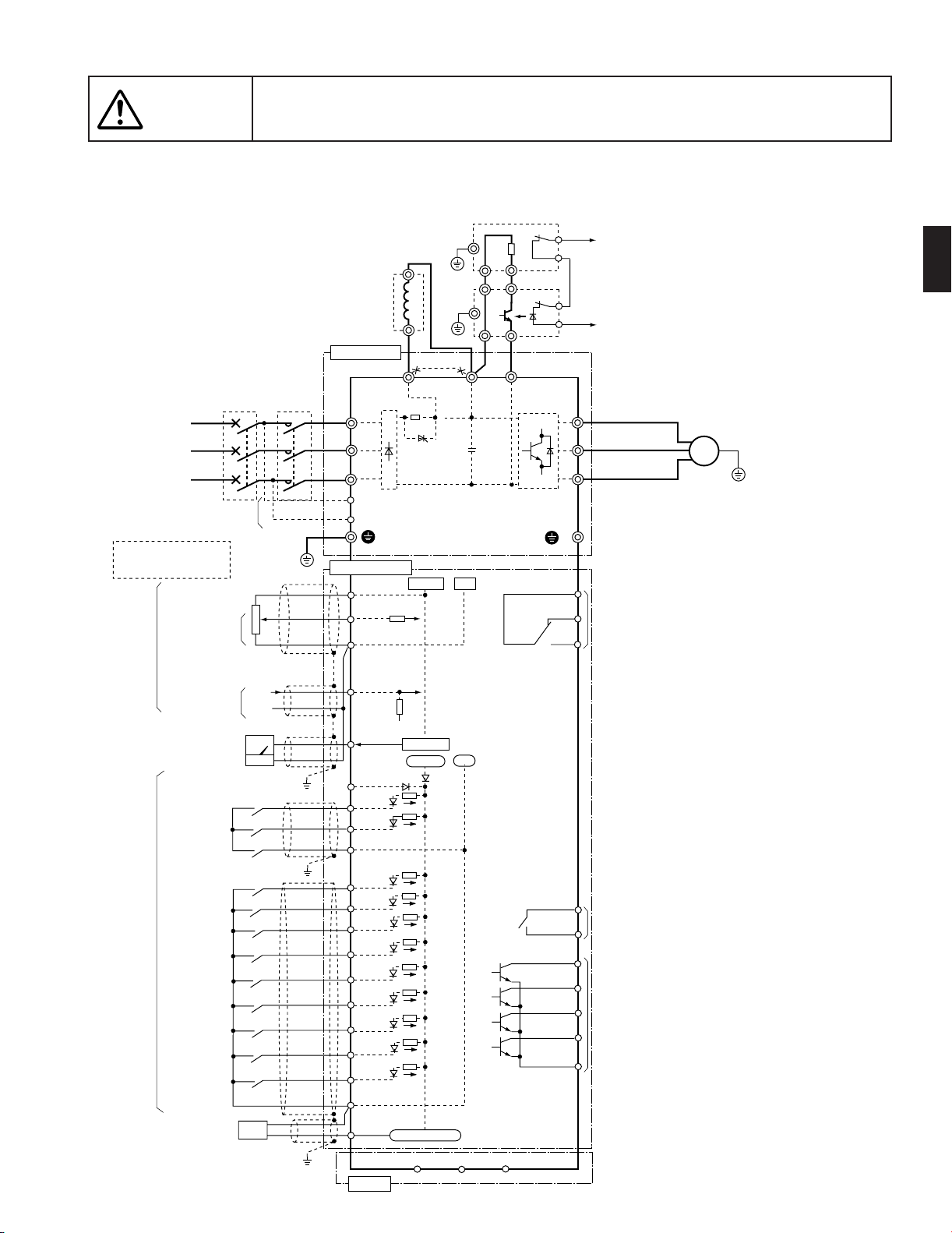
The information described in this document is for the purpose of selecting the
Caution
appropriate product only. Before actually using this product, be sure to read the
Instruction Manual carefully to ensure proper operation.
(3) 230V/460V FRENIC5000G11S : 15 to 30HP
FRENIC5000P11S : 20 to 30HP
G
DC REACTOR (DCR)
(*2) (*4)
Power supply ( *1)
3-phase
200 to 230V
50/60Hz
or
3-phase
400 to 480V
50/60Hz
It is possible to input voltage
signals (0 to +10Vdc or 0 to
+5Vdc) to terminals [12]-[11]
instead of the potentiometer.
Analog input
Digital input
Potentiometer
power supply (*2)
Analog frequency meter
MCCB
or
GFCI
Auxiliary control
power supply (*7)
Voltage input
0 to 10Vdc
Current input
4 to 20mAdc
0 to 60Hz
FM (*2)
(*3)
Grounding
3
2
1
(+)
(–)
MC
(*3)
Main circuit
L1/R
L2/S
L3/T
(R0)
(T0)
G
Control circuit
[13]
[12]
[11]
[C1]
[FMA]
(PLC)
(FWD)
(REV)
(CM)
(X1)
(X2)
(X3)
(X4)
(X5)
(X6)
(X7)
(X8)
(X9)
(CM)
(*7)
P1
SR
+10Vdc
0〜10Vdc
+24Vdc
External braking resistor (DB) (*2)(*5)
2
P
DB
1
P
DB
2
N
0V
0V
P
Braking unit (BU) (*2)(*6)
N(-)
P(+)
30
<Y5C>
<Y5A>
<CME>
1
U
V
W
G
30C
30B
30A
<Y4>
<Y3>
<Y2>
<Y1>
G
3. Wiring Diagram
(CM)
(THR)
Motor
M
G
(*8)
Alarm output (for any fault)
NOTE: Common terminals [11], (CM), and <CME> for
control circuits are isolated from one another.
(*1) Use the inverter whose rated input voltage
matches the power supply voltage.
(*2) An optional device. Use it when necessary.
(*3) Use this peripheral device when necessary.
(*4) When connecting a DC REACTOR (DCR),
remove the jumper wire (*7) that connects
the terminals [P1] and [P(+)].
(*5) When connecting an optional external braking
resistor (DB), be sure to also use an optional
braking unit (*6).
(*6) Connect the optional braking unit to the [P(+)]
and [N(-)] terminals.
Auxiliary terminals [1] and [2] have polarity.
Be sure to connect cables to these terminals
correctly. (See the diagram)
(*7) Even if these terminals are not powered,
the inverter can be operated.
(*8) Terminal for grounding the motor.
Connect it, if necessary.
Relay output
Transistor output
Chapter 1
1
Digital frequency meter
(pulse counter) (*2)
60Hz
(FMP)
RS-485
Pulse output
(DX-)
(DX+)
(SD)
1-31
Page 38

Chapter 1
3. Wiring Diagram
The information described in this document is for the purpose of selecting the
Caution
(4) 230V/460V FRENIC5000G11S : 40 to 125HP / 40 to 600HP
MCCB
or
GFCI
Power supply ( *1)
3-phase
200 to 230V
50/60Hz
or
3-phase
400 to 480V
50/60Hz
It is possible to input voltage
signals (0 to +10Vdc or 0 to
+5Vdc) to terminals [12]-[11]
instead of the potentiometer.
Analog
input
Digital
input
Digital frequency meter
Auxiliary control
power supply (*7)
Potentiometer
power supply (*2)
Voltage input
0 to 10Vdc
Current input
4 to 20mAdc
Analog frequency meter
0 to 60Hz
FM (*2)
(pulse counter) (*2)
(*3)
60Hz
appropriate product only. Before actually using this product, be sure to read the
Instruction Manual carefully to ensure proper operation.
FRENIC5000P11S : 40 to 150HP / 40 to 800HP
External braking resistor (DB) (*2)(*5)
P
DB
P
DB
N
P
Braking unit (BU) (*2)(*6)
N(-)
P(+)
30
(SD)
MC
(*3)
Grounding
3
2
1
(+)
(–)
DC REACTOR (DCR)
(*2) (*4)
Main circuit
L1/R
L2/S
L3/T
(R0)
(T0)
Control circuit
[13]
[12]
[11]
[C1]
[FMA]
(PLC)
(FWD)
(REV)
(CM)
(X1)
(X2)
(X3)
(X4)
(X5)
(X6)
(X7)
(X8)
(X9)
(CM)
(FMP)
RS-485
P1
G
Pulse output
(DX-)
(*8)
SR
73
+10Vdc
0〜10Vdc
+24Vdc
G
G
CNUX (∗)
U1 U2
0V
0V
(DX+)
2
1
2
1
W
G
30C
30B
30A
<Y5C>
<Y5A>
<Y4>
<Y3>
<Y2>
<Y1>
<CME>
(CM)
(THR)
U
V
(*8)
Alarm output (for any fault)
NOTE: Common terminals [11], (CM), and <CME> for
control circuits are isolated from one another.
(*1) Use the inverter whose rated input voltage
matches the power supply voltage.
(*2) An optional device. Use it when necessary.
(*3) Use this peripheral device when necessary.
(*4) [75HP or smaller]
When connecting DC REACTOR (DCR),
remove the jumper wire (*8) that connects
the terminals [P1] and [P(+)].
[100HP or larger]
Terminals [P1] and [P(+)] are not connected at
shipment from factory.
A DC REACTOR (DCR) is provided as standard
in JE version.
(Separately installed)
Be sure to connect the DCR.
(*5) When connecting an optional external braking
resistor (DB), be sure to also use an optional
braking unit (*6).
(*6) Connect the optional braking unit to the [P(+)]
and [N(-)] terminals.
Relay
output
Transistor
output
(∗)
400 to 440V/50Hz, 440 to 480V/60Hz
380V/50Hz (398V or smaller),
380 to 415V/60Hz (430V or smaller)
Auxiliary terminals [1] and [2] have polarity.
Be sure to connect cables to these terminals
correctly. (See the diagram)
(*7) Even if these terminals are not powered, the
inverter can be operated.
(*8) Terminal for grounding the motor.
Connect it, if necessary.
Input voltage
Motor
M
G
U1
U2
CNUX connector
1-32
Page 39
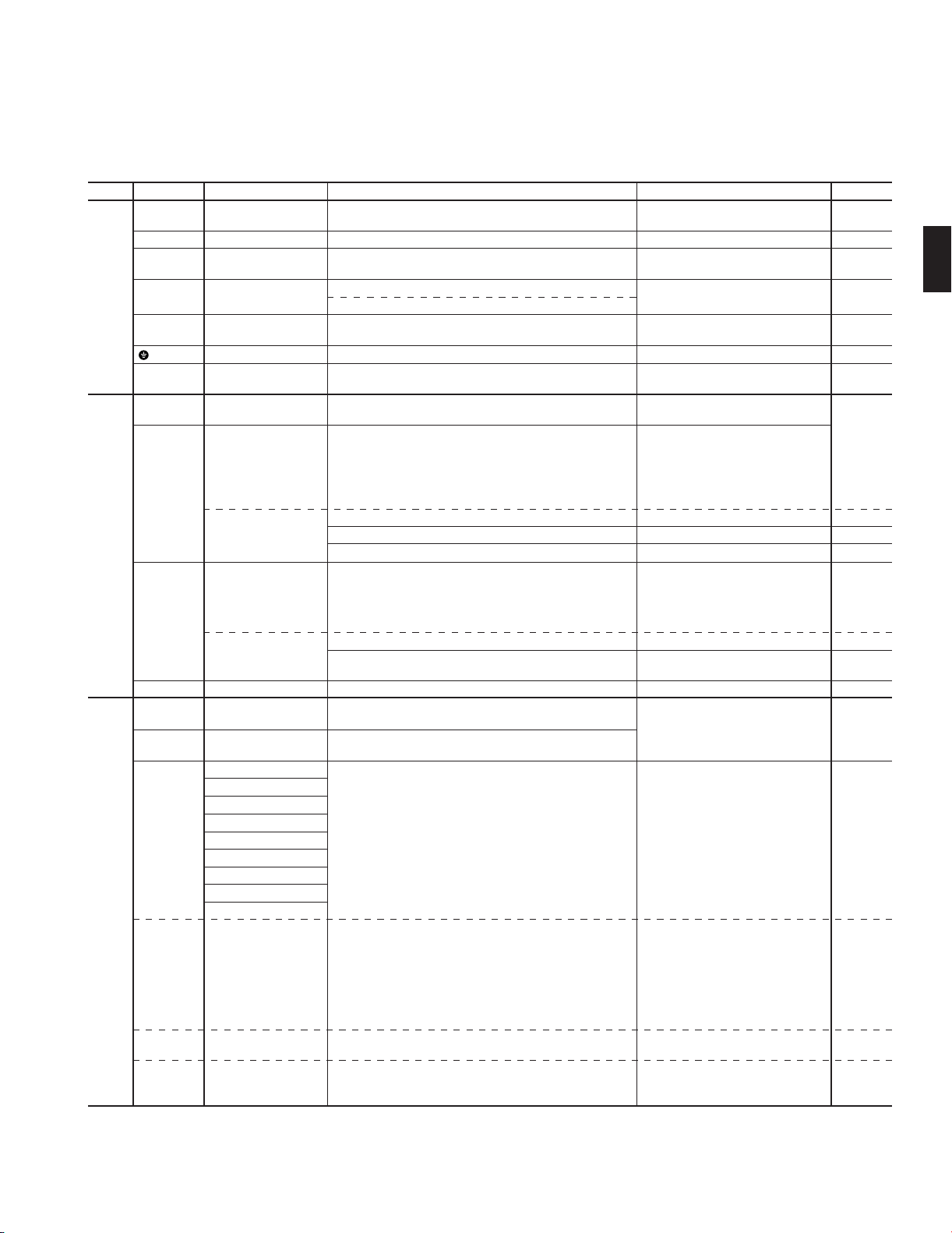
4. Terminal
4.1 Terminal functions
Symbol Terminal name Functions Remarks Func. code
L1/R, L2/S, Power input
Main
L3/T
circuit
U, V, W Inverter output
P1, P(+) For DC REACTOR
P(+), N(-) For BRAKING UNIT
P(+), DB For EXTERNAL
G Grounding
R0, T0 Auxiliary control
13 Potentiometer
Analog
input
12 Voltage input
C1 Current input
11 Common
Digital
FWD Forward operation
input
REV Reverse operation
X1 Digital input 1
X2 Digital input 2
X3 Digital input 3
X4 Digital input 4
X5 Digital input 5
X6 Digital input 6
X7 Digital input 7
X8 Digital input 8
X9 Digital input 9
BRAKING RESISTOR
power supply
power supply
(Reversible operation)
(Inverse mode operation)
(Torque control)
(Inverse mode operation)
(PTC thermistor input)
commond
commond
(SS1) Multistep freq.
(SS2) selection
(SS4)
(SS8)
(RT1) ACC / DEC time
(RT2) selection
(HLD) 3-wire operation
stop command
(PID control)
(PG feedback)
(PID control)
Connect a 3-phase power supply.
Connect a 3-phase induction motor.
Connect the DC REACTOR for power-factor correcting or
harmonic current reducing.
• Connect the BRAKING UNIT (Option).
• Used for DC bus connection system.
Connect the EXTERNAL BRAKING RESISTOR (Option)
Ground terminal for inverter chassis (housing).
Connect the same AC power supply as that of the main circuit
to back up the control circuit power supply.
+10V DC power supply for frequency setting POT ( POT: 1 to 5kΩ )
•0 to +10V DC/0 to 100% (0 to +5V DC/0 to 100% )
•Selected by function setting.
0 to ±10V DC /0 to ±100% (0 to ±5V DC/0 to ±100% )
(Setting resolution of 0 to ± 10V DC is twice.)
• Selected by function setting or digital input signal.
+10 to 0V DC/0 to 100%
Used for torque control reference signal.
Used for PID control reference signal or feedback signal.
Used for reference signal of PG feedback control (option)
•4 to 20mA DC/0 to 100%
• Selected by function setting or digital input signal.
20 to 4mA DC/0 to 100%
Used for PID control reference signal or feedback signal.
The PTC thermisor (for motor protection) can be connnected
to terminal 13-C1-11.
Common for analog signal
FWD : ON ......... The motor runs in the forward direction.
FWD : OFF ........ The motor decelerates and stops.
REV : ON ......... The motor runs in the reverse direction.
REV : OFF ........ The motor decelerates and stops.
These terminals can be preset as follows.
(SS1) : 2 (0, 1) different frequencies are
selectable.
(SS1,SS2) : 4 (0 to 3) different frequencies are
selectable.
(SS1,SS2,SS4) : 8 (0 to 7) different frequencies are
selectable.
(SS1,SS2,SS4,SS8) : 16 (0 to 15) different frequencies are
selectable.
(RT1) : 2 (0, 1) different ACC / DEC times are selectable.
(RT1,RT2): 4 (0 to 3) different ACC / DEC times are selectable.
Used for 3-wire operation.
(HLD): ON ..... The inverter self-holds FWD or REV signal.
(HLD): OFF ... The inverter releases self-holding.
DC REACTOR: Option
(for 75HP or smaller)
BRAKING UNIT (Option): G11S:15HP
or larger, P11S: 20HP or larger
Only for 10HP or smaller (G11S),
15HP or smaller (P11S)
1HP or smaller: Not correspond
·Allowable maximum output current :
10mA
·Input impedance: 22kΩ
· Allowable maximum input voltage:
±15V DC
· If input voltage is 10 to 15V DC, the
inverter estimates it to10V DC.
·Input impedance: 250Ω
·Allowable maximum input current:
30mA DC
· If input current is 20 to 30mA DC ,
the inverter estimates it to 20mA DC.
Isolated from terminal CME and CM.
When FWD and REV are simulta-
neously ON, the motor decelerates
and stops.
· ON state maximum input voltage: 2V
(maximum source current : 5mA)
· OFF state maximum terminal
voltage: 22 to 27V
(allowable maximum leakage
current: 0.5mA)
Frequency 0 is set by F01 (or C30).
(All signals of SS1 to SS8 are OFF)
Time 0 is set by F07/F08.
(All signals of RT1 to RT2 are OFF)
Assigned to terminal X7 at factory
setting.
Chapter 1
4. Terminal
1
F01, C30
H18
F01, H21
F01, H21
H26, H27
F02
E01 to E09
C05 to C19
F07, F08
E10 to E15
1-33
Page 40

Chapter 1
4. Terminal
Digital
input
Symbol Terminal name Functions Remarks Func. code
(BX) Coast-to-stop
command
(RST) Alarm reset
(THR) Trip command
(External fault)
(JOG) Jogging operation
(Hz2/Hz1) Freq. set 2 / Freq. set 1
(M2/M1) Motor 2 / Motor 1
(DCBRK) DC brake command
(TL2/TL1) Torque limiter 2 /
Torque limiter 1
(SW50) Switching operation
between line and
inverter (50Hz)
(SW60) Switching operation
between line and
inverter (60Hz)
(UP) UP command
(DOWN) DOWN command
(WE-KP) Write enable for KEYPAD
(Hz/PID) PID control cancel
(IVS) Inverse mode changeover
(IL) Interlock signal for 52-2
(Hz/TRQ) TRQ control cancel
(LE) Link enable (RS-485, Bus)
(U-DI) Universal DI
(STM) Pick up start mode
(PG/Hz) SY-PG enabled
(SYC) Synchronization
command
(ZERO) Zero speed command
(BX): ON ........ The inverter output is cut off immediately and
(RST): ON ...... Faults are reset. (This signal should be held
(THR): OFF ....
• The inverter output is cut off and the motor coasts-to-stop.
Alarm signal will be output.
• This signal is held internally and is reset by inputting RST signal.
• Used to protect overheating of external braking resistor.
(JOG): ON .... JOG frequency is effective.
(Hz2/Hz1): ON ..... Freq. set 2 is effective.
(M2/M1): ON .......The motor circuit parameter and V/f
(DCBRK): ON ..... The DC inUXction brake is effective. (In the
(TL2/TL1): ON .... Torque limiter 2 is effective.
(SW50(SW60)): ON
The motor is changed from inverter operation to line operation.
(SW50(SW60)): OFF
The motor is changed from line operation to inverter operation.
(UP): ON ........... The output frequency increases.
(DOWN): ON .... The output frequency decreases.
· The output frequency change rate is determined by ACC /
DEC time.
· Restarting frequency can be selected from 0Hz or setting
value at the time of stop.
(WE-KP): ON .... The data is changed by KEYPAD.
(Hz/PID): ON .... The PID control is canceled, and frequency
(IVS): ON ... Inverse mode is effective in analog signal input.
When a switch is connected between inverter and motor,
connect its auxiliary NC contact to this terminal.
When a momentary power failure occurs, this signal is input.
(Hz/TRQ): ON ... The torque control is canceled, and ordinary
(LE): ON ........... The link opereation is effective. Used to
This signal is transmitted to main controller of LINK operation.
(STM): ON ........ The "Pick up" start mode is effective.
(PG/Hz): ON ..... Synchronized operation or PG-feedback
(SYC): ON ........ The motor is controlled for synchronized
(ZERO): ON ...... The motor speed is controlled with the
the motor will coast-to-stop. (No alarm signal
will be output.)
for more than 0.1s.)
characteristics are changed to the second
motor's ones.
inverter deceleration mode)
setting by KEYPAD (
effective.
operation is effective.
switch operation between ordinary operation
and link operation to communication.
operation is effective.
operation between 2 axes with PGs.
speed reference of zero.
∨
or
)is
∨
· The motor restarts from 0Hz by
turning off BX with the operation
command (FWD or REV) ON.
· Assigned to terminal X8 at factory
setting.
· During normal operating, this signal
is ignored.
· Assigned to terminal X9 at factory
setting.
This alarm signal is held internally.
This signal is effective only while the
inverter is stopping.
If this signal is changed while the
inverter is running, the signal is
effective only after the inverter stops.
If this signal is changed while the
inverter is running, the signal is
effective only after the inverter stops.
If the operation command(FWD/REV)
is input while DC braking is effective,
the operation command (FWD/REV)
has priority.
Main circuit changeover signals are
output through Y1 to Y5 terminal.
When UP and DOWN commands are
simultaneously ON, DOWN signal is
effective.
If this signal is changed while the
inverter is running, the signal is
effective only after the inverter stops.
RS-485: Standard, Bus: Option
Option
Option
This function can be selected at PG
feedback control. Option
C20
C30, F01
A10 to A18,
P01 to P09
F20 to F22
E16, E17,
F40, F41
F01,C30
F00
H20 to H25
F01, C30
H18
H30
H09
1-34
Page 41

Symbol Terminal name Functions Remarks Func. code
Digital
input
Analog
output
Pulse
output
Transistor
output
(STOP1) Forced stop command
(STOP2) Forced stop command
(EXITE) Pre-exciting command
PLC PLC terminal
CM Common
FMA Analog monitor
(11) (Common)
FMP Pulse rate monitor
(CM) (Common)
Y1 Transistor output 1
Y2 Transistor output 2
Y3 Transistor output 3
Y4 Transistor output 4
(RUN) Inverter running
(FAR) Frequency equivalence
(FDT1) Frequency level
(LU) Undervoltage
(B/D) Torque polarity
(TL) Torque limiting
(IPF) Auto-restarting
with Deceleration time4
signal
detection
detection signal
(STOP1): OFF .. The motor decelerates and stops.
(STOP2): OFF .. The motor decelerates and stops with
Deceleration time4.
(EXITE): ON ..... The magnetic flux can be established preliminary
before starting at PG vector mode.
Connect PLC power supply to avoid malfunction of the inveter
that has SINK type digital input,when PLC power supply is off.
Common for digital signal.
Output voltage (0 to 10V DC) is proportional to selected
function’s value as follows.
The proportional coefficient and bias value can be preset.
•Output frequency 1 (Before slip compensation)
( 0 to max. frequency )
• Output frequency 2 (After slip compensation)
( 0 to max. frequency )
• Output current ( 0 to 200% )
• Output voltage ( 0 to 200% )
• Output torque ( 0 to 200% )
• Load factor ( 0 to 200% )
•Input power ( 0 to 200% )
•PID feedback value ( 0 to 100% )
•PG feedback value ( 0 to max. speed )
• DC link circuit voltage ( 0 to 1000V)
•Universal AO ( 0 to 100%)
• Pulse rate mode : Pulse rate is proportional to selected
function’s value (50% duty pulse)
•Average voltage mode : Average voltage is proportional to
selected function’s value (2670p/s pulse width control)
•Output frequency 1 (Before slip compensation)
(0 to max. frequency )
• Output frequency 2 (After slip compensation)
( 0 to max. frequency )
• Output current ( 0 to 200% )
• Output voltage ( 0 to 200% )
• Output torque ( 0 to 200% )
• Load factor ( 0 to 200% )
•Input power ( 0 to 200% )
•PID feedback value ( 0 to 100% )
•PG feedback value ( 0 to max. speed )
• DC link circuit voltage ( 0 to 500V: 230V)
(0 to 1000V: 460V)
•Universal AO ( 0 to 100%)
Output the selected signals from the following items.
Outputs ON signal when the output frequency is higher than
starting frequency.
Outputs ON signal when the difference between output
frequency and setting frequency is smaller than FAR
hysteresis width.
Outputs ON signal by comparison of output frequency and
preset value (level and hysteresis).
Outputs ON signal when the inverter stops by undervoltage
while the operation command is ON.
Outputs ON signal in braking or stopping mode, and OFF
signal in driving mode.
Outputs ON signal when the inverter is in torque-limiting
mode.
Outputs ON signal during auto restart operation (Instantaneous power failure) mode. (including "restart time")
Chapter 1
4. Terminal
Er6 is indicated after the motor stops.
E15
Isolated from terminals CME and 11.
•Allowable maximum output current:
2mA
• Up to two analog voltmeters can be
connnected (Input impedance :
10kΩ)
•Allowable maximum output current:
2mA
• Up to two analog voltmeters can be
connnected (Input impedance :
10kΩ)
• ON state maximum output voltage :
2V
(Allowable maximum sink current : 50mA)
•
OFF state maximum leakage current : 0.1mA
(Allowable maximum voltage : 27V)
•Operation level
G11S : 0 to 400Hz, P11S : 0 to 120Hz
• Hysteresis width : 0.0 to 30.0Hz
F30 to F31
F33 to F35
E20 to E23
E30
E31, E32
1
1-35
Page 42

Chapter 1
4. Terminal
Transistor
output
CME Common (transistor
30A, 30B Alarm relay output
Relay
30C
output
Y5A, Y5C Relay output
DX+, DX-, RS-485 I/O terminal
LINK
SD
Symbol Terminal name Functions Remarks Func. code
(OL1) Overload early
warning
(KP) KEYPAD operation mode
(STP) Inverter stopping
(RDY) Ready output
(SW88) Line/Inv changeover
(for 88)
(SW52-2) Line/Inv changeover
(for 52-2)
(SW52-1) Line/Inv changeover
(for 52-1)
(SWM2) Motor2/Motor1
(AX) Auxiliary terminal
(for 52-1)
(TU) Time-up signal
(TO) Cycle completion signal
(STG1) Stage No. indication 1
(STG2) Stage No. indication 2
(STG4) Stage No. indication 4
(AL1) Alarm indication 1
(AL2) Alarm indication 2
(AL4) Alarm indication 4
(AL8) Alarm indication 8
(FAN) Fan operation signal
(TRY) Auto-resetting
(U-DO) Universal DO
(OH) Overheat early warning
(SY) Synchronization
completion signal
(LIFE) Lifetime alarm
(FDT2) 2nd Freq. level
detection
(OL2) 2nd OL level early
warning
(C1OFF) Terminal C1 off signal
(DNZS) Speed existence signal
output)
• Outputs ON signal when the electronic thermal value is
higher than preset alarm level.
•Outputs ON signal when the output current value is higher
than preset alarm level.
Outputs ON signal when the inverter is in KEYPAD operation mode.
Outputs ON signal when the inverter is in stopping mode or in
DC braking mode.
Outputs ON signal when the inverter is ready for operation.
Outputs 88's ON signal to a switch for line operation in Line/
Inverter changeover operation.
Outputs 52-2’s ON signal to a switch on inverter power supply
side in Line/Inverter changeover operation.
Outputs 52-1’s ON signal to a switch on inverter output side in
Line/Inverter changeover operation.
Outputs the motor changeover switch ON signal from motor 1
to motor 2.
Used for auxiliary circuit of 52-1.
(Same function as AX1, AX2 terminal by FRENIC5000G9S
series. (40HP or larger))
Outputs time up signal (100ms ON pulse) at every stage end
of PATTERN operation.
Outputs one cycle completion signal (100ms ON pulse) at
PATTERN operation.
Outputs PATTERN operation’s stage No. by signals STG1,
STG2, and STG4.
Outputs trip alarm No. by signals AL1, AL2, AL4, and AL8.
Outputs the inverter cooling fan operation status signal.
Outputs ON signal at auto resetting mode. (Including "Reset
interval")
Outputs command signal from main controller of LINK
operation.
Outputs ON signal when the temperature difference between the
heat sink and the trip level is less than 10°C (50°F), and outputs OFF
signal when the temperature difference is more than 15°C (59°F).
Synchronization completion signal for synchronized operation.
Outputs ON signal when the calculated lifetime is longer than
preset alarm level.
2nd-outputs ON signal by comparison of output frequency and
preset value (FDT2 level).
2nd-outputs ON signal when the output current value is larger
than preset alarm level (OL2 level).
Outputs ON signal when the C1 current is smaller than 2mA.
Outputs ON signal at detection of motor speed when using
OPC-G11S-PG/PG2/SY.
Common for transistor output signal.
Isolated from terminals CM and 11.
Outputs a contact signal when a protective function is
activated.
Changeable exciting mode active or non-exciting mode active
by function "F36".
Functions can be selected the same as Y1 to Y4.
Changeable exciting mode active or non-exciting mode active
by function "E25".
Used for closing/opening a magnetic contactor connected to
main power supply input.
• Connect to a personal computer or programmable logic
controller (PLC).
• Up to 31 inverters can be connected when using daisy chain
connection.
Refer to wiring diagram example.
40HP or larger only.
Option
· Contact rating :
250V AC, 0.3A, cosø=0.3
48V DC, 0.5A, non-inductive
E33 to E35
F02
A01 to A18
C21 to C28
H06
H04, H05
F36
E24
E25
1-36
Page 43

4.2 Main circuit and control circuit terminals
T0
R0
Inverter
Main circuit terminal
Control
circuit
terminal
T0
R0
Inverter
Main circuit terminal
Control
circuit
terminal
4.2.1 Terminal block arrangement
Table 1-1 Terminal block arrangement
Chapter 1
4. Terminal
Power Nominal G11S series P11S series
supply applied
voltage motor [HP]
Threephase
230V
Threephase
460V
NOTES: R0 and T0 are not provided with inverters of 1HP or smaller.
Inverter type Fig. No. Inverter type Fig. No.
1/4
FRNF25G11S-2UX
1/2
FRNF50G11S-2UX
1
FRN001G11S-2UX
2
FRN002G11S-2UX
3
FRN003G11S-2UX
5
FRN005G11S-2UX
7.5
FRN007G11S-2UX FRN007P11S-2UX
10
FRN010G11S-2UX FRN010P11S-2UX
15
FRN015G11S-2UX
20
FRN020G11S-2UX FRN020P11S-2UX
25
FRN025G11S-2UX FRN025P11S-2UX
30
FRN030G11S-2UX FRN030P11S-2UX
40
FRN040G11S-2UX
50
FRN050G11S-2UX FRN050P11S-2UX
60
FRN060G11S-2UX
75
FRN075G11S-2UX FRN075P11S-2UX
100
FRN100G11S-2UX
125
FRN125G11S-2UX
150 – –
1/2
FRNF50G11S-4UX
1
FRN001G11S-4UX
2
FRN002G11S-4UX
3
FRN003G11S-4UX
5
FRN005G11S-4UX
7.5
FRN007G11S-4UX FRN007P11S-4UX
10
FRN010G11S-4UX FRN010P11S-4UX
15
FRN015G11S-4UX
20
FRN020G11S-4UX FRN020P11S-4UX
25
FRN025G11S-4UX FRN025P11S-4UX
30
FRN030G11S-4UX FRN030P11S-4UX
40
FRN040G11S-4UX FRN040P11S-4UX
50
FRN050G11S-4UX
60
FRN060G11S-4UX FRN060P11S-4UX
75
FRN075G11S-4UX FRN075P11S-4UX
100
FRN100G11S-4UX FRN100P11S-4UX
125
FRN125G11S-4UX
150
FRN150G11S-4UX FRN150P11S-4UX
200
FRN200G11S-4UX
250
FRN250G11S-4UX FRN250P11S-4UX
300
FRN300G11S-4UX FRN300P11S-4UX
350
FRN350G11S-4UX FRN350P11S-4UX
400
FRN400G11S-4UX
450
FRN450G11S-4UX FRN450P11S-4UX
500
FRN500G11S-4UX FRN500P11S-4UX
600
FRN600G11S-4UX FRN600P11S-4UX
700 –
800 –
1––
FRN015P11S-2UX
2
3
FRN040P11S-2UX
4
FRN060P11S-2UX
5
FRN100P11S-2UX
7
FRN125P11S-2UX
FRN150P11S-2UX
1––
2
FRN015P11S-4UX
FRN050P11S-4UX
3
4
FRN125P11S-4UX
FRN200P11S-4UX
6
FRN400P11S-4UX
7
FRN700P11S-4UX
–
FRN800P11S-4UX
Te rminal block arrangement
Fig.1 Fig.2
2
Fig.3 Fig.4
Inverter
3
4
Control
circuit
terminal
5
7
T0R0
Main circuit terminal
Fig.5 Fig.6
2
Inverter
R0
T0
Main circuit terminal
Control
circuit
terminal
3
Fig.7
4
6
7
Inverter
Control
circuit
terminal
T0R0
Main circuit terminal
Inverter
Control
circuit
terminal
T0R0
Main circuit terminal
Inverter
Control
circuit
terminal
T0R0
Main circuit terminal
1
1-37
Page 44

Chapter 1
4. Terminal
4.2.2 Main circuit terminal
■ Main circuit terminal arrangement
(a) Three-phase 230V
Table 1-2 (a) Main circuit terminal arrangement
Power Nominal G11S series P11S series
supply applied
voltage motor [HP]
1/4
Inverter type Fig. No. Inverter type Fig. No.
FRNF25G11S-2UX
Te rminal arrangement
Fig.1
Threephase
230V
1/2
7.5
FRNF50G11S-2UX
1
FRN001G11S-2UX
2
FRN002G11S-2UX
3
FRN003G11S-2UX
5
FRN005G11S-2UX
FRN007G11S-2UX
2, 10
3, 11
10
15
20
FRN010G11S-2UX FRN010P11S-2UX
FRN015G11S-2UX FRN015P11S-2UX
FRN020G11S-2UX
4, 11
25
30
40
50
FRN025G11S-2UX FRN025P11S-2UX
FRN030G11S-2UX FRN030P11S-2UX
FRN040G11S-2UX FRN040P11S-2UX
FRN050G11S-2UX
5, 11
60
75
100
125
FRN060G11S-2UX FRN060P11S-2UX
FRN075G11S-2UX FRN075P11S-2UX
FRN100G11S-2UX
FRN125G11S-2UX
6, 11
7, 11
150 – –
1
FRN007P11S-2UX
FRN020P11S-2UX
FRN050P11S-2UX
FRN100P11S-2UX
FRN125P11S-2UX
FRN150P11S-2UX
––
Fig.2
3, 11
Fig.3
4, 11
5, 11
Fig.4
6, 11
7, 11
L1/R
L2/S L3/T DB P1 P(+) N(–) U V W
G
G
L1/R
L2/S L3/T DB P1 P(+) N(—) U V W
G
G
L1/R
L2/S L3/T DB P1 P(+) N(–) U V W
L1/R
L2/S L3/T P1 P(+) N(–) U V W
G
G
G
G
NOTE: See Table 1-2 (b) for Fig.5 and later.
1-38
Page 45

(b) Three-phase 460V
UP1 V W
P(+) N(–)
G
G
L1/R
L2/S L3/T
UP1 V W
P(+) N(–)
L1/R
L2/S L3/T
Chapter 1
4. Terminal
Table 1-2 (b) Main circuit terminal arrangement
Power Nominal G11S series P11S series
supply applied
voltage motor [HP]
1/2
Inverter type Fig. No. Inverter type Fig. No.
FRNF50G11S-4UX
1
1
FRN001G11S-4UX
2
FRN002G11S-4UX
3
FRN003G11S-4UX
5
FRN005G11S-4UX
7.5
FRN007G11S-4UX
2, 10
FRN007P11S-4UX
––
3,11
10
FRN010G11S-4UX FRN010P11S-4UX
15
FRN015G11S-4UX FRN015P11S-4UX
20
FRN020G11S-4UX
FRN020P11S-4UX
4, 11
25
FRN025G11S-4UX FRN025P11S-4UX
30
FRN030G11S-4UX FRN030P11S-4UX
40
FRN040G11S-4UX FRN040P11S-4UX
50
FRN050G11S-4UX FRN050P11S-4UX
Threephase
460V
60
FRN060G11S-4UX FRN060P11S-4UX
75
FRN075G11S-4UX
100
FRN100G11S-4UX FRN100P11S-4UX
125
FRN125G11S-4UX FRN125P11S-4UX
150
FRN150G11S-4UX FRN150P11S-4UX
5, 11
FRN075P11S-4UX
3, 11
4, 11
5, 11
Fig.5
Fig.6
L1/R
Fig.7
Fig.8
Fig.9
L1/R
Te rminal arrangement
VW
U
L2/S L3/T
L1/R
L3/T P1 N(–)P(+) U V W
L2/S
G
G
L1/R
G
L2/S
L1/R
L2/S
G
P1
P(+)
G
G
L2/S L3/T U V W
P1 P(+) N(–)
G
UP1 V W
UVW
P(+) P(+)
L3/T
L3/T
P1
G
1
N(–)
N(–) N(–)
200
FRN200G11S-4UX FRN200P11S-4UX
250
FRN250G11S-4UX
300
FRN300G11S-4UX FRN300P11S-4UX
350
FRN350G11S-4UX FRN350P11S-4UX
400
FRN400G11S-4UX
450
FRN450G11S-4UX FRN450P11S-4UX
500
FRN500G11S-4UX
600
FRN600G11S-4UX FRN600P11S-4UX
700 –
800 –
NOTES: See Table 1-2 (a) for Fig. 1 to Fig. 4.
7, 11
8, 12
9, 12
–
FRN250P11S-4UX
FRN400P11S-4UX
FRN500P11S-4UX
FRN700P11S-4UX
FRN800P11S-4UX
7, 11
8, 12
9, 12
Fig.10
Fig.11
R0
T0
R0 T0
Fig.12
R0 T0
1-39
Page 46

Chapter 1
4. Terminal
■ Main circuit terminal size
Table 1-3 Main circuit terminal size (G11S/P11S)
Power Nominal Inverter type Terminal size Inverter type Terminal size
supply applied
voltage motor [HP] U, V, W N (-) *1) U, V, W N (-) *1)
1/4 FRNF25G11S-2UX
1/2 FRNF50G11S-2UX M3.5 M3.5 M3.5 M3.5 –
1 FRN001G11S-2UX – –
2 FRN002G11S-2UX
3 FRN003G11S-2UX M4 M4 M4 M4 M3.5
5 FRN005G11S-2UX
7.5 FRN007G11S-2UX
Threephase
230V
Threephase
460V
10 FRN010G11S-2UX FRN010P11S-2UX M5 M5 M5 M5 M3.5
15 FRN015G11S-2UX FRN015P11S-2UX
20 FRN020G11S-2UX
25 FRN025G11S-2UX FRN025P11S-2UX M6 M6 M6 M6 M3.5
30 FRN030G11S-2UX FRN030P11S-2UX
40 FRN040G11S-2UX M8 M8 FRN040P11S-2UX
50 FRN050G11S-2UX –
60 FRN060G11S-2UX M10 M10 FRN060P11S-2UX M8 M4
75 FRN075G11S-2UX FRN075P11S-2UX M10 M10 –
100 FRN100G11S-2UX
125 FRN125G11S-2UX FRN125P11S-2UX
150 – – – – – FRN150P11S-2UX
1/2 FRNF50G11S-4UX
1 FRN001G11S-4UX
2 FRN002G11S-4UX – –
3 FRN003G11S-4UX M4 M4 M4 M4 M3.5
5 FRN005G11S-4UX
7.5 FRN007G11S-4UX
10 FRN010G11S-4UX FRN010P11S-4UX M5 M5 M5 M5 M3.5
15 FRN015G11S-4UX FRN015P11S-4UX
20 FRN020G11S-4UX
25 FRN025G11S-4UX FRN025P11S-4UX M6 M6 M6 M6 M3.5
30 FRN030G11S-4UX FRN030P11S-4UX
40 FRN040G11S-4UX FRN040P11S-4UX
50 FRN050G11S-4UX M8 M8 FRN050P11S-4UX
60 FRN060G11S-4UX FRN060P11S-4UX M8 M8
75 FRN075G11S-4UX – M8 M4 FRN075P11S-4UX
100 FRN100G11S-4UX FRN100P11S-4UX
125 FRN125G11S-4UX M10 M10 FRN125P11S-4UX –
150 FRN150G11S-4UX FRN150P11S-4UX M10 M10
200 FRN200G11S-4UX FRN200P11S-4UX
250 FRN250G11S-4UX FRN250P11S-4UX
300 FRN300G11S-4UX FRN300P11S-4UX
350 FRN350G11S-4UX
400 FRN400G11S-4UX FRN400P11S-4UX
450 FRN450G11S-4UX FRN450P11S-4UX M12 M12 M10 M4
500 FRN500G11S-4UX FRN500P11S-4UX
600 FRN600G11S-4UX FRN600P11S-4UX
700 –
800 – FRN800P11S-4UX
G11S series
NOTES: *1) Provided as standard for 2HP or larger inverter. (Not available for 1HP or smaller inverter)
L1/R, L2/S. L3/T P1,P (+) DB
M5 M5 M5 M5 M3.5
M6 M6 M6 M3.5
M12 M12 M10 M4
M3.5 M3.5 M3.5 M3.5 –
M5 M5 M5 M5 M3.5
M6 M6 M6 M3.5
M12 M12 M10 M4
–
G R0,T0
M8 M4
P11S series
FRN007P11S-2UX
FRN020P11S-2UX
FRN050P11S-2UX
FRN100P11S-2UX
FRN007P11S-4UX
FRN020P11S-4UX
FRN350P11S-4UX
FRN700P11S-4UX
L1/R, L2/S. L3/T P1,P (+) DB G R0,T0
M8 M8
M12 M12 M10 M4
M8 M4
1-40
Page 47

4.2.3 Control circuit terminal
30C
30A
30B
Y5A
Y3
Y1
C1
FMP
PLC
X1
X2
X3
X4
X5
X6
FMA
Y5C
Y4
Y2
CME
11
12
13
CM
FWD
REV
CM
X7
X8
X9
DX-
DX+
SD
■ Control circuit terminal size and arrangement
Table 1-5 Control circuit terminal size and arrangement
Chapter 1
4. Terminal
Nominal applied Inverter type Control circuit terminal
motor [HP]
1/4 FRNF25G11S-2UX M3
1/2
1
2
3
5
7.5
10
15
20
25
30
40
50
60
75
100
125
150
200 FRN200G11S-4UX FRN200P11S-4UX
250 FRN250G11S-4UX FRN250P11S-4UX
300 FRN300G11S-4UX FRN300P11S-4UX
350 FRN350G11S-4UX FRN350P11S-4UX
400 FRN400G11S-4UX FRN400P11S-4UX
450 FRN450G11S-4UX FRN450P11S-4UX
500 FRN500G11S-4UX FRN500P11S-4UX
600 FRN600G11S-4UX FRN600P11S-4UX
700 – FRN700P11S-4UX
800 – FRN800P11S-4UX
G11S series P11S series Screw size Terminal arrangement
FRNF50G11S-2UX
FRNF50G11S-4UX
FRN001G11S-2UX
FRN001G11S-4UX
FRN002G11S-2UX –
FRN002G11S-4UX
FRN003G11S-2UX
FRN003G11S-4UX
FRN005G11S-2UX
FRN005G11S-4UX
FRN007G11S-2UX FRN007P11S-2UX
FRN007G11S-4UX FRN007P11S-4UX
FRN010G11S-2UX FRN010P11S-2UX
FRN010G11S-4UX FRN010P11S-4UX
FRN015G11S-2UX FRN015P11S-2UX
FRN015G11S-4UX FRN015P11S-4UX
FRN020G11S-2UX FRN020P11S-2UX
FRN020G11S-4UX FRN020P11S-4UX
FRN025G11S-2UX FRN025P11S-2UX
FRN025G11S-4UX FRN025P11S-4UX
FRN030G11S-2UX FRN030P11S-2UX
FRN030G11S-4UX FRN030P11S-4UX
FRN040G11S-2UX FRN040P11S-2UX
FRN040G11S-4UX FRN040P11S-4UX
FRN050G11S-2UX FRN050P11S-2UX
FRN050G11S-4UX FRN050P11S-4UX
FRN060G11S-2UX FRN060P11S-2UX
FRN060G11S-4UX FRN060P11S-4UX
FRN075G11S-2UX FRN075P11S-2UX
FRN075G11S-4UX FRN075P11S-4UX
FRN100G11S-2UX FRN100P11S-2UX
FRN100G11S-4UX FRN100P11S-4UX
FRN125G11S-2UX FRN125P11S-2UX
FRN125G11S-4UX FRN125P11S-4UX
– FRN150P11S-2UX
FRN150G11S-4UX FRN150P11S-4UX
1
1-41
Page 48

Chapter 1
4. Terminal
■ Terminal size
M2.5:Common for all models
1-42
Page 49

Chapter 2
Operation
Contents
1. Frequency Control Operation .............................................................................2-2
1.1 Types of frequency control signal........................................................................ 2-2
1.2 Accuracy and resolution...................................................................................... 2-3
2. KEYPAD panel ....................................................................................................... 2-4
3. Function Explanation ........................................................................................... 2-6
3.1 Fundamental Functions ...................................................................................... 2-6
3.2 Extension Terminal Functions ........................................................................... 2-16
3.3 Control Functions of Frequency ........................................................................2-26
3.4 Motor Parameters ............................................................................................. 2-31
3.5 High Performance Functions ............................................................................2-33
3.6 Alternative Motor Parameters ...........................................................................2-42
4. Standard RS-485 Interface ................................................................................. 2-44
4.1 Outline............................................................................................................... 2-45
4.1.1 Features..................................................................................................... 2-45
4.1.2 Function overview ...................................................................................... 2-45
4.2 Transmission specification ................................................................................2-45
4.3 Connection ........................................................................................................ 2-45
4.3.1 Connection method.................................................................................... 2-45
4.3.2 RS-485....................................................................................................... 2-46
4.3.3 Example of connection of FRENIC5000G11S/P11S series ...................... 2-46
4.3.4 Example of noise prevention...................................................................... 2-47
4.4 Transmission method ........................................................................................ 2-47
4.4.1 Transmission frame.................................................................................... 2-47
4.4.2 Field description......................................................................................... 2-53
4.4.3 Procedure on the host side ........................................................................ 2-54
4.4.4 Example of communication........................................................................ 2-56
4.4.5 Communication error ................................................................................. 2-57
4.5 Functions specific for communication ............................................................... 2-61
4.5.1 Command data .......................................................................................... 2-61
4.5.2 Operation command data .......................................................................... 2-61
4.5.3 Function data .............................................................................................2-62
4.5.4 Monitoring data ..........................................................................................2-63
4.6 Function data format ......................................................................................... 2-64
4.6.1 List of function data format ........................................................................ 2-64
4.6.2 Data format specification ........................................................................... 2-67
4.7 Changeover of communications ....................................................................... 2-69
4.7.1 Changeover method for communication valid/invalid................................. 2-70
4.7.2 Link function (operation selection) .............................................................2-70
4.7.3 Coexistence of link (option) and RS-485 communication ..........................2-70
4.8 Response Time .................................................................................................2-70
4.8.1 Response interval time .............................................................................. 2-70
4.8.2 Time of receiving preparation completion .................................................. 2-71
4.9 Function ............................................................................................................2-71
4.10 Troubleshooting ................................................................................................2-72
4.11 Appendix ...........................................................................................................2-73
4.11.1 Communication level converter .................................................................2-73
4.11.2 ASCII code list .......................................................................................... 2-73
4.11.3 Example of a control program ................................................................... 2-74
2
5. Using Lifetime Forecast Functions ...................................................................2-75
5.1 Contents of lifetime forecast functions .............................................................. 2-75
5.2 How to check lifetime forecast information........................................................ 2-75
5.3 Measuring conditions of lifetime........................................................................ 2-76
2-1
Page 50

Chapter 2
1.Frequency Control Operation
1. Frequency Control Operation
1.1 Types of frequency control signal
17 types of frequency setting method are available as shown on Table 2-1.
Table 2-1 List of Frequency setting method
No. Frequency setting method Description Related Func. Code
G11S, P11S
1 KEYPAD operation
2 External potentiometer
30 to +10V voltage input
40 to +5V voltage input
54 to 20mA current input
6Voltage input + current
70 to
8 +10 to 0V voltage input
9 20 to 4mA current input
10 UP/DOWN control
11 Multistep speed operation
12 Jogging operation
13 Pattern operation
14 D/I or pulse train
, keys)
(
input
+
10V voltage input
-
• While the
and while the
• Connect a potentiometer (1 to 5kΩ) with three terminals to the
terminals 13, 12, and 11 to perform frequency control.
•At that time, +10Vdc is applied between terminals 13 and 11.
Therefore, use a potentiometer of 1 to 5k. (The maximum
allowable current between terminals is 10mA)
•Potentiometer is sold separately.
• Input a 0 to +10Vdc signal between the terminals 12 and 11 to
perform frequency control. (Input impedance = 22kΩ)
• By setting Function code F17 (Gain for frequency setting signal)
at 200.0%, 0 to 5Vdc signal can be used for frequency setting.
• Input a 0 to +5Vdc signal between the terminals 12 and 11 to
perform frequency control. (Input impedance = 22kΩ)
• Input a 4 to 20mAdc current signal between the terminals C1
and 11 to perform frequency control. (Input impedance = 250Ω)
• Use an added signal of voltage signal of 0 to 10Vdc (between
terminals 12 and 11) + current signal of 4 to 20mAdc (between
terminals C1 and 11) to perform frequency control.
• Invert the polarity of the DC voltage signal, in addition to the
control of item 3 above, to change the rotating direction.
• Input a +10 to 0Vdc voltage signal between the terminals 12 and
11 (or V2 and 11) to perform frequency control in inverse
mode.(Input impedance = 22k ), (+10 to 0V / 0Hz to Max. freq.)
• Input a 20 to 4mAdc current signal between the terminals C1
and 11 to perform frequency control in inverse mode.(Input
impedance = 250 ), (20 to 4mA / 0Hz to Max. freq.)
• Set UP/DOWN control to the terminal function of digital input
terminal. Output frequency increases while UP terminal is on; it
decreases while DOWN terminal is on.
• Output frequency at starting can be selected from either 0Hz or
the value last set before stopping.
• 15 kinds of output frequency can be stored in the inverter. Each
output frequency can be selected by external signals (assigned
to terminals X1 to X9) to perform multistep (max. 16) speed
operation.
• Jogging operation can be set by KEYPAD panel or external
signal input.
• An automatic timer operation can be performed according to the
preset max. 7 stages.
External setting from PLC is not required.
• Highly precise speed control can be performed with 16-bit
parallel signal using an option card (OPC-G11S-DIO). Either 16bit binary signal or BCD 4-digit signal can be selected.
• Speed control with pulse train input can be performed using an
option card (OPC-G11S-PGM).
• Using an option card (OPC-G11S-SY) enables the position
control with pulse train input and the synchronous operation
between two motors (simultaneous-start-and-synchronization,
proportional synchronization).
key is pressed, the output frequency increases
key is pressed, it decreases.
F01
F01
F01
F01
F01
F01
F01
F01
F01
F01
E01 to E09
F01
E01 to E09
F02
E01 to E09
F01
C21 to C28
F01
2-2
Page 51

Chapter 2
1. Frequency Control Operation
No. Frequency setting method Description Related Func. Code
G11S, P11S
15 RS-485 communication
16 PID control
17 T-link
18 LINK operation
* In G11S series, output frequency can be selected out of 2 preset frequency signals by using external signal input (Function select of terminal X1
to X9).
•Frequency setting can be made by means of communication
with RS-485 as standard.
• Optimum control is enabled, by controlling feedback signal in airconditioning unit.
• Highly precise speed control can be performed with 16-bit serial
signal by connecting FUJI PLC “MICREX-F” via an option card
(OPC-G11S-TL).
• Using the option cads (OPC-G11S-MMM) below enables
several types of communications.
• Profibus-DP, DeviceNet, Modbus Plus, Interbus-S, CAN open
H30 to H39
H20 to H25
F01, H30
2
1.2 Accuracy and resolution
Accuracy and resolution depend on the frequency setting type as follows:
Table 2-2 Accuracy of frequency setting
Type of setting Accuracy Remarks
Analog setting ±0.2% of Maximum frequency 25 ± 10°C (77 ± 50°F)
Digital setting ± 0.01% of Maximum frequency -10 to +50°C (14 to 122°F)
Table 2-3 Resolution of frequency setting
Type of setting Resolution Remarks
Analog setting 1/3000 of Maximum frequency
KEYPAD panel setting 0.01Hz at 99.99Hz or lower
0.1Hz at 100.0Hz or higher
LINK setting 1/20000 of Maximum frequency or 0.01Hz (Fixed) Either one can be selected.
2-3
Page 52

Chapter 2
2. KEYPAD Panel
2. KEYPAD panel
LED monitor
In operation mode:
Displays the setting frequency,
output current, voltage, motor
speed, or line speed.
In trip mode:
Displays code indicating the
cause of trip.
Up/Down keys
In operation mode :
Increases or decreases the
frequency or speed.
In program mode :
Increases or decreases function
code number and data set value.
Program key
Switches the display to a menu
screen or to the initial screen for
operation mode or alarm mode.
RUN
RUN
LCD monitor
In operation mode :
Displays various items of
information such as operation
condition and function data.
Operation guidance, which
can be scrolled, is displayed
at the bottom.
In program mode :
Displays functions and data.
Unit indication
Displays the unit for the
information shown on the LED
monitor.
FWD/REV keys
In operation mode :
Starts the inverter with
forward or reverse operation
command.
Pressing the FWD or REV
key lights the RUN lamp.
Invalid when the function
code F02 (Operation method)
is set at 1 (External signal
operation).
2-4
Shift key (Column shift)
In program mode :
Moves the cursor horizontally at
data change. Pressing this key
with the UP or DOWN key, the
screen changes to the next
function block.
Reset key
In program mode :
Cancels the current input data
and shifts the screen.
In trip mode :
Releases the trip-stop state.
Stop key
In operation mode :
Stops the inverter.
Invalid when the function code
F02 (Operation method) is set
at 1 (External signal
operation).
Function/Data Select key
In operation mode :
Changes the displayed values
of LED monitor.
In program mode :
Selects the function code or
stores the data.
Page 53

Chapter 2
2. KEYPAD Panel
■ KEYPAD panel Operation
Perform the wiring shown in the Basic wiring diagram in Section 3.2, Chapter 1. Turn on inverter power, and use the
or key to set an output frequency. Press the
The inverter starts running using the factory setting function data.
Press the
key to stop the inverter.
STOP
• Procedure for selecting function codes and data codes
The following is a sample procedure for selecting a function code and changing the function data.
FUNC
key, then press the
DATA
FWD
or
REV
key.
q Press the
PRG
key to switch the operation monitor screen to the program
menu screen.
w Select “1. DATA SET” , and press the
FUNC
DATA
key.
e Press the or key to select a target function code. To quickly
scroll the function select screen, press
key at the same time. At the target function, press the
r Use the , , and
target value. (Use the
FUNCSHIFT
FUNCSHIFT
keys to change the function data to the
key to move the cursor when you want to
FUNCSHIFT
key and the or
FUNC
DATA
key.
enter a numerical value.)
FUNC
t Press the
DATA
key to store the updated function data in memory.
The screen shifts for the selection of the next function.
RUN FWD
PRG → PRG MENU
F/D → LED SHIFT
2
→ 1. DATA SET
2. DATA CHECK
3. OPR MNTR
4. I / O CHECK
F00 DATA PRTC
F01 FREQ CMD 1
F02 OPR METHOD
F03 MAX Hz-1
F01 FREQ CMD 1
0
0 ~ 11
F02 OPR METHOD
F03 MAX Hz-1
F04 BASE Hz-1
F05 RATED V-1
y Pressing the
screen.
PRG
key switches the screen to the operation monitor
RUN FWD
PRG → PRG MENU
F/D → LED SHIFT
1) Setting a frequency
When the operation monitor screen is displayed, a frequency can be set by using the or key in both the
operation and stop modes. When the target frequency is displayed, press the
FUNC
key to enter the frequency in
DATA
memory.
2) Switching a unit indication
During both operation and stop modes, each time the
FUNC
DATA
key is pressed, the value displayed on the LED monitor
changes, and the unit indication on the LCD monitor shifts from Hz to A, V, r/min, m/min, kW, and % in this order in
accordance with the displayed value.
2-5
Page 54

Chapter 2
3. Function Explanation
3. Function Explanation
3.1 Fundamental Functions
■ F00 Data protection
F00 DATA PRTC
Setting can be made so that a set value cannot be changed by
KEYPAD panel operation.
- Set value 0: The data can be changed.
1: The data cannot be changed.
[Setting procedure]
0 → 1 : Press the
change the value from 0 to 1, then press the
key to validate the change.
1 → 0 : Press the
change the value from 1 to 0, then press the
key to validate the change.
■ F01 Frequency command 1
F01 FREQ CMD1
This function selects the frequency setting method.
0: Setting by KEYPAD panel operation (
1: Setting by voltage input (terminal 12) (0 to +10Vdc, 0 to
5Vdc).
2: Setting by current input (terminal C1) (4 to 20mAdc).
3: Setting by voltage input + current input (terminal 12 +
terminal C1) (0 to +10V + 4 to 20mA).
The setting frequency is determined by adding inputs to
terminals 12 and C1.
4: Reversible operation with polarized voltage input (terminal
12). (-10 to +10Vdc)
5: Reversible operation with polarized voltage input (terminal
12) + voltage command auxiliary input (optional terminal
V1) (-10 to +10Vdc)
The setting frequency is determined by adding inputs to
terminals 12 and V1.
* Polarized input allows operation in the direction opposite
that of an operation command.
6: Inverse mode operation (terminal 12) (+10 to 0Vdc)
7: Inverse mode operation (terminal C1) (20 to 4mA)
8: Setting by UP/DOWN control mode 1 (initial value = 0)
(terminals UP and DOWN)
9: Setting by UP/DOWN control mode 2 (initial value = last
final value) (terminals UP and DOWN)
See the function explanation of E01 to E09 for details.
10: Setting by PATTERN operation
11: Setting by DI option or Pulse train input (Option)
For details, see the instruction manual on options.
and keys simultaneously to
STOP
and keys simultaneously to
STOP
E01 to E09
, key).
FUNC
DATA
FUNC
DATA
E01 to E09
C21 to C28
• “ ” means the related functions and the set value
• Forward and inverse operation
Frequency setting value
Maximum frequency
(set value: 1, 3)
-10
(set value: 4, 5 )
- Maximum frequency
Frequency setting value
Maximum frequency
0
Analog input terminal (12), (V1)
004 20 mA
Analog input terminal (C1)
Forward operation
(set value: 1, 3, 4, 5)
Inverse operation
(set value: 6)
+10V
V1: Option
Forward operation
(set value: 2, 3)
Inverse operation
(set value: 7)
■ F02 Operation method
F02 OPR METHOD
This function sets the operation command input method.
- Set value 0: KEYPAD operation (
keys).
Input from terminals FWD and REV is ignored.
1: Operation by external input (terminals FWD
and REV).
• This function can only be changed when terminals FWD and
REV are open.
• REMOTE/LOCAL switching from the KEYPAD panel
automatically changes the set value of this function.
FWD, REV
, and
STOP
2-6
Page 55

[LE]
Chapter 2
3. Function Explanation
Frequency
setting signals
[Hz2/Hz1]
[C1]
Option
[SS1]
[SS2]
[SS4]
[SS8]
[JOG]
[Hz2/PID]
[V1]
[IVS]
[UP]
[DOWN]
Frequency setting
Frequency setting by
KEYPAD panel
Offset
C31
[12]
+
+
Offset
C32
+
+
#5
C33
D/I or pulse train (optional)
PATTERN
operation control
F01 C30
+
+
+
+
Analog input filter
UP/DOWN control
C22
C23
C24
C25
C26
C27
Inverse
operation
Inverse
operation
C21
C05
C06
C07
C08
C09
C10
#0
#4
#3
#2
#7
#6
#1, #5
#8,#9
#10
#11
C12
C13
C14
C15
C16
C17
Normal/
inverse
operation
Gain
F17 F18
Multistep freq.
switching
Bias
frequency
Negative
polarity
prevention
#1,#2,#3,#6,#7
H30
Set frequency
value by
LINK function
Multistep frequencies 1 to 15
JOG frequency
C20
Feedback
selection
H21 H25
PID control
H20
H22
H23
H24
Feedback filter
Operation
selection
Proportional
Integral
Differential
Limit signal
Max. freq.
High limiter
Jump frequency
C01
C02
C03
C04
Low limiter
Limiter processing
F03 A01
F15
F16
Set frequency
value
2
C18
C28
C11
C19
Switching
command
*1) JE version EN version
Offset
C31
[C1]
[12]
+
+
Offset
C32
+
+
[12]
[C1]
*2) [V2] .... EN only
Frequency setting block diagram
Gain Bias
C31 C32
2-7
Page 56

Chapter 2
3. Function Explanation
■ F03 Maximum frequency 1
F03 MAX Hz-1
This function sets the maximum output frequency for motor 1.
- Setting range G11S: 50 to 400Hz
P11S: 50 to 120Hz
Setting a value higher than the rated value of the equipment to
be driven may damage the motor or machine. Match this
value with the rating of the equipment.
■ F04 Base frequency 1
F04 BASE Hz-1
This function sets the maximum output frequency in the
constant-torque range of motor 1 or the output frequency at
the rated output voltage. Match this value with he rating of the
motor.
- Setting range G11S: 25 to 400Hz
P11S: 25 to 120Hz
NOTE:
When the set value of base frequency 1 is higher than that of
maximum output frequency 1, the output voltage does not increase to
the rated voltage because the maximum frequency limits the output
frequency.
Output voltage
Constant-torque range
F06 Maximum
voltage 1
F05 Rated
voltage 1
■ F07 Acceleration time 1
■ F08 Deceleration time 1
F07 ACC TIME1
F08 DEC TIME1
This function sets the acceleration time for the output frequency from startup to maximum frequency and the deceleration time from maximum frequency to operation stop.
- Setting range Acceleration time 1: 0.01 to 3600s
Deceleration time 1: 0.01 to 3600s
Acceleration and deceleration times are represented by the
three most significant digits, thereby the setting of three highorder digits can be set.
Set acceleration and deceleration times with respect to
maximum frequency. The relationship between the set
frequency value and acceleration/deceleration times is as
follows:
Set frequency = maximum frequency
The actual operation time matches the set value.
Start Stop
Maximum frequency
Output
frequency
Set frequency
Time
Output
frequency
0
F04 Base
frequency 1
F03 Maximum
frequency
■ F05 Rated voltage 1
F05 RATED V-1
This function sets the rated value of the voltage output to
motor 1. Note that a voltage higher than the supply (input)
voltage cannot be output.
- Setting range 230V: 0, 80 to 240V
460V: 0, 320 to 480V
Value 0 terminates operation of the voltage regulation function,
thereby resulting in the output of a voltage proportional to the
supply voltage.
NOTE:
When the set value of rated voltage 1 exceeds maximum output
voltage 1, the output voltage does not increase to the rated voltage
because the maximum output voltage limits the output voltage.
■ F06 Maximum voltage 1
F06 MAX V-1
This function sets the maximum value of the voltage output for
motor 1. Note that a voltage higher than the supply (input)
voltage cannot be output.
- Setting range 230V: 80 to 240V
460V: 320 to 480V
Acceleration time Deceleration time
Set frequency < maximum frequency
The actual operation time differs from the set value.
Acceleration/deceleration operation time
= set value x (set frequency/maximum frequency)
StopStart
Maximum frequency
Output
frequency
Acceleration
operation time
Acceleration time Deceleration time
NOTE:
If the set acceleration and deceleration times are too short even
though the resistance torque and moment of inertia of the load are
great, the torque limiting function or stall prevention function is
activated, thereby prolonging the operation time beyond that stated
above.
Deceleration
operation time
Set frequency
Time
2-8
Page 57

Chapter 2
3. Function Explanation
■ F09 Torque boost 1
F09 TRQ BOOST1
This is a motor 1 function. The following can be selected:
- Selection of load characteristics such as automatic torque
boost, variable torque load, proportional torque load,
constant torque load.
- Enhancement of torque (V/f characteristics), which is
lowered during low-speed operation. Insufficient magnetic
flux of the motor due to a voltage drop in the low-frequency
range can be compensated.
Setting range Characteristics selected
0.0 Automatic torque boost characteristic where the
0.1 to 0.9 Variable torque characteristics for fan and pump
1.0 to 1.9 Proportional torque for middle class loads
2.0 to 20.0 Constant torque (linear change)
Torque characteristics
Variable torque Proportional torque
Output voltage V
100%
torque boost value of a constant torque load (a
linear change) is automatically adjusted
loads
between variable torque and constant torque
(linear change)
Output voltage V
Rated voltage 1
100%
Rated voltage 1
current value flows for the time set by F12 (thermal time
constant).
F10 ELCTRN OL1
This function specifies whether to operate the electronic
thermal O/L relay and selects the target motor. When a
standard motor is selected, the operation level is lowered in
the low speed range according to the cooling characteristics of
the motor.
- Set value 0: Inactive
1: Active (for standard motor)
2: Active (for inverter motor)
F11 OL LEVEL1
This function sets the operation level (current value) of the
electronic thermal. Enter a value from 1 to 1.1 times the
current rating value of the motor.
The setting range is 20 to 135% of the rated current of the
inverter.
Operation level current and output current
When F10 = 2
100
95
90
85
Operation
level current
(%)
69
54
1/4 to 30HP
(When F10 = 1)
40 to 60HP
(When F10 = 1)
fe = fb (fb < 60Hz)
fb: Base frequency
{
60Hz (fb > 60Hz)
2
#0.9
10%
0
Output frequency f
Constant torque
Output voltage V
100%
10%
0
NOTE:
As a large torque boost value creates over-excitation in the low-speed
range, continued operation may cause the motor to overheating.
Check the characteristics of the driven motor.
■
F10 Electronic thermal O/L relay for motor 1(Select)
Base
frequency 1
#0.1
Rated voltage 1
#20.0
#2.0
Output frequency f
Base
frequency 1
10%
#1.9
0
#1.0
Output frequency f
Base
frequency 1
■ F11 Electronic thermal O/L relay (Level)
■ F12 Electronic thermal O/L relay (Thermal time
constant)
The electronic thermal O/L relay manages the output frequency, output current, and operation time of the inverter to
prevent the motor from overheating when 150% of the set
feX0.33
feX0.83 fe f0 (Hz)
Output frequency
F12 TIME CNST 1
The time from when 150% of the operation level current flows
continuously to when the electronic thermal O/L relay activates
can be set.
- Setting range : 0.5 to 75.0 min (in 0.1 min steps)
Current-operation time characteristics example
20
15
Operation
time (min)
10
5
0
0
(Output current /operation level current) x 100 (%)
50 100 150 200
Changed by F12.
F12=10
F12=5
F12=0.5
2-9
Page 58

Chapter 2
3. Function Explanation
■ F13 Electronic thermal O/L relay (for braking
resistor)
F13 DBR OL
This function controls the frequent use and continuous
operating time of the braking resistor to prevent the resistor
from overheating.
Inverter capacity Operation
G11S: 10HP or less 0: Inactive
P11S: 15HP or less 0: Inactive
G11S: 15HP or more
P11S: 20HP or more
Operation after momentary power failure
Set value
G11S/P11S
0
1
2
3
4
5
Function name Operation at power failure Operation at power recovery
Inactive
(immediate inverter trip)
Inactive
(inverter trip at recovery)
Inactive
(inverter trip after
deceleration to a stop at
powerfailure)
Active
(operation continued, for
high-inertia loads)
Active
(restart with the frequency
at power failure)
Active
(restart with the starting
frequency, for low-inertia
loads)
1: Active (built-in braking resistor)
2: Active (external braking resistor)
2: Active (external braking resistor)
0: Inactive
If undervoltage is detected, the protective function is
activated and output stops.
If undervoltage is detected, the protective function is
not activated, but output stops.
When the operation continuation level (H15) is
reached, deceleration to a stop occurs. The DC
voltage of the main circuit sharpens the deceleration
slope so that the undervoltage protective function is
not activated. The inverter collects the inertia energy of
the load and control the motor until it stops, then the
undervoltage protective function is activated. If the
amount of inertia energy from the load is small, and the
undervoltage level is achieved during deceleration, the
undervoltage protective function is then activated.
When the operation continuation level is achieved,
energy is collected from the inertia amount of the load
to extend the operation continuation time.
If undervoltage is detected, the protective function is
not activated, but output stops.
If undervoltage is detected, the protective function is
not activated and output stops.
If undervoltage is detected, the protective function is
not activated and output stops.
■ F14 Restart mode after momentary power failure
(Select)
F14 RESTART
This function selects operation if momentary power failure
occurs.
The function for detecting power failure and activating
protective operation (i.e., alarm output, alarm display, inverter
output cutoff) for undervoltage can be selected. The automatic restart function (for automatically restarting a coasting
motor without stopping) when the supply voltage is recovered
can also be selected.
- Setting range: 0 to 5
The following table lists the function details.
Inverter is not
restarted.
The protective
function is activated,
but operation is not
restarted.
The protective
function is activated,
and operation is not
restarted.
Operation is automatically restarted.
For power recovery during operation continuation, rotation accelerates directly to the original
frequency. If undervoltage is detected,
operation automatically restarts with the
frequency at that time.
Operation is automatically restarted with the
frequency at power failure.
Operation is automatically restarted with the
frequency set by F23, “Starting frequency.”
Inputting the protective function reset
command and
operation command
restarts operation.
• Function codes H13 to H16 are provided to control a restarting operation after momentary power failure. These functions should
be understood and used.
• The rotating motor pick-up (speed search) function can also be selected as a method of restarting when power is recovered
following a momentary failure. (For setting details, see function code H09.)
• The pick-up function searches for the speed of the coasting motor to restart the motor without subjecting it to excessive shock.
• In a high-inertia system, the reduction in motor speed is minimal even when the motor is coasting. A speed searching time is
required when the pick-up function is active. In such a case, the original frequency may be recovered sooner when the pick-up
function is inactive and the operation restarted with the frequency prior to the momentary power failure.
• The pick-up function works in the range of 5 to 120Hz. If the detected speed is outside this range, restart the motor using the
regular restart function.
2-10
Page 59

Chapter 2
3. Function Explanation
Set value : 0 Set value : 3
Power failure Power recovery
DC link circuit
voltage
Output
frequency
LV trip
Set value : 1
DC link circuit
voltage
Output
frequency
Undervoltage
Time
ON
Undervoltage
Time
DC link circuit
voltage
Output
frequency
(motor speed)
LV trip
Output
(terminals Y1 to Y5)
Set value : 4
DC link circuit
voltage
Power failure Power recovery
H15
Operation
continuation level
2
Undervoltage
LV trip
Set value : 2
DC link circuit
voltage
Output
frequency
LV trip
H15
Operation
continuation level
ON
ON
(terminals Y1 to Y5)
Time
Output
frequency
(motor speed)
LV trip
Output
Set value : 5
DC link circuit
voltage
Output
frequency
(motor speed)
LV trip
H13 :
Waiting time
ON
Undervoltage
H13 : Waiting time
Synchronization
Acceleration
(terminals Y1 to Y5)
Output
ON
NOTE : Dotted-dashed lines indicate motor speed.
2-11
Page 60

Chapter 2
3. Function Explanation
■ F15 Frequency limiter (High)
■ F16 Frequency limiter (Low)
F15 H LIMITER
F16 L LIMITER
This function sets the upper and lower limits for the setting
frequency .
- Set values: G11S: 0 to 400Hz
P11S: 0 to 120Hz
Output frequency
+ Maximum frequency
High limiter
Set
frequency
+100%
-100%
Low limiter
Low limiter
High limiter
- Maximum frequency
■ F18 Bias frequency
F18 FREQ BIAS
This function adds a bias frequency to the set frequency value
to analog input.
The operation follows the figure below.
When the bias frequency is higher than the maximum frequency or lower than the – (minus) maximum frequency, it is
limited to the maximum or –maximum frequency.
Set frequency
Maximum frequency
-10
–Maximum frequency
0
4
Bias frequency
(when positive)
Analog input
+10V
20mA
Bias frequency
(when negative)
(Terminal 12)
(Terminal C1)
* The inverter output starts with the starting frequency when operation
begins, and stops with the stop frequency when operation ends.
* If the upper limit value is less than the lower limit value, the upper
limit value overrides the lower limit value.
■ F17 Gain (for frequency setting signal)
F17 FREQ GAIN
This function sets the rate of the set frequency value to analog
input.
Operation follows the figure below.
Set frequency
200%
Maximum frequency
-10
04+5V
12mA
100%
50%
+10V
20mA
Analog input
(Terminal 12)
(Terminal C1)
■ F20 DC brake (Starting freq.)
■ F21 DC brake (Braking level)
■ F22 DC brake (Braking time)
F20 DC BRK Hz
Starting frequency: This function sets the frequency at which
DC injection brake starts operation during deceleration, to
decelerate the motor to a stop.
- Set values:0.0 to 60.0Hz
F21 DC BRK LVL
Operation level: This function sets the output current level
when a DC injection brake is activated. Set a percentage of
inverter rated output current in 1% steps.
- Set values: G11S: 0 to 100%
P11S: 0 to 80%
F22 DC BRK t
Time: This function sets the time of a DC injection brake
operation.
- Set value 0.0: Inactive
0.1 to 30.0s
Do not use the inverter brake
CAUTION
function for mechanical
holding. Injury may result.
2-12
- Maximum frequency
Page 61

Chapter 2
3. Function Explanation
■ F23 Starting frequency (Freq.)
■ F24 Starting frequency (Holding time)
■ F25 Stop frequency
The starting frequency can be set to reserve the torque at
startup and can be sustained until the magnetic flux of the
motor is being established.
F23 START Hz
Frequency: This function sets the frequency at startup.
- Set values: 0.1 to 60.0Hz
F24 HOLDING t
Holding time: This function sets the holding time during which
the start frequency is sustained at startup.
- Set values: 0.1 to 10.0s
* The holding time does not apply at the time of switching between
forward and reverse.
* The holding time is not included in the acceleration time.
* The holding time also applies when pattern operation (C21) is
selected. The holding time is included in the timer value.
F25 STOP Hz
This function sets the frequency at stop.
- Set values: 0.1 to 6.0Hz
Output frequency
Forward
rotation
NOTES:
1. Reducing the set value adversely affects the output current
waveform (i.e., higher harmonics), increases motor loss, and raises
motor temperature. For example, at 0.75kHz, reduce the motor torque
by about 15%.
2. Increasing the set value increases inverter loss and raises inverter
temperature.
■ F27 Motor sound (Sound tone)
F27 MTR TONE
The tone of motor sound can be altered when the carrier
frequency is 7kHz or lower. Use this function as required.
- Set values: 0, 1, 2, 3
■ F30 FMA (Voltage adjust)
■ F31 FMA (Function)
Monitor data (e.g., output frequency, output current) can be
output to terminal FMA as a DC voltage. The amplitude of the
output can also be adjusted.
F30 FMA V-ADJ
This function adjusts the voltage value of the monitor item
selected in F31 when the monitor amount is 100%. A value
from 0 to 200 (%) can be set in 1% steps.
- Set values: 0 to 200%
Higher than 10V
10V
F30:200%
F30:100%
2
Holding time
Starting frequency
Stop frequency
Time
The operation does not start when the starting frequency is
less than the stop frequency or when the setting frequency is
less than the stop frequency.
■ F26 Motor sound (Carrier freq.)
F26 MTR SOUND
This function adjusts the carrier frequency, correct adjustment
of which prevents resonance with the machine system,
reduces motor sound and inverter noise, and also reduces
leakage current from output circuit wiring.
Series Nominal applied motor Setting range
G11S
P11S
Carrier frequency Low High
Motor sound High Low
Output current waveform Bad Good
Leakage current Small Large
Noise occurrence Extremely low High
75HP or less 0.75 to 15kHz
100HP or more 0.75 to 10kHz
30HP or less 0.75 to 15kHz
40 to 100HP 0.75 to 10kHz
125HP or more 0.75 to 6kHz
FMA terminal
output voltage
5V
F30:50%
F30:0%
100%50%
F31 FMA FUNC
This function selects the monitor item to be output to terminal FMA.
Set value Monitor item
0 Output frequency 1 Maximum output frequency
1 Output frequency 2 Maximum output frequency
2 Output current Rated output current of inverter x 2
3 Output voltage Maximum output voltage of inverter
4 Output torque Rated torque of motor x 2
5 Load factor Rated load of motor x 2
6Input power Rated output of inverter x 2
7PID feedback value Feedback value of 100%
8PG feedback value
9 DC link circuit voltage 230V: 500V
10 Universal AO 0 to 10V
Definition of 100% monitor amount
(before slip compensation)
(after slip compensation)
(230V: 250V, 460V: 500V)
Synchronous speed at maximum frequency
(only when option is installed)
460V: 1000V
2-13
Page 62

Chapter 2
3. Function Explanation
■ F33 FMP terminal (Pulse rate)
■ F34 FMP terminal (Voltage adjust)
■ F35 FMP terminal (Function)
Monitor data (e.g., output frequency, output current) can be
output to terminal FMP as pulse voltage. Monitor data can also
be sent to an analog meter as average voltage.
When sending data to a digital counter or other instrument as
pulse output, set the pulse rate in F33 to any value and the
voltage in F34 to 0%.
When data is sent to an analog meter or other instrument as
average voltage, the voltage value set in F34 determines the
average voltage and the pulse rate in F33 is fixed to 2670 (p/s).
F33 FMP PULSES
This function sets the pulse frequency of the monitor item
selected in F35 within a range of 300 to 6000p/s in 1 p/s
steps.
- Set values: 300 to 6000 p/s
T1
15.6V (Typical)
T
Pulse cycle time
Pulse frequency (p/s) = 1/T
Duty (%) = T1/T x 100
Average voltage (V) = 15.6 x T1/T
F34 FMP V-ADJ
This function sets the average voltage of pulse output to
terminal FMP.
Set values
0% : The pulse frequency varies depending on the
monitor amount of the monitor item selected in
F35. (The maximum value is the value set in
F33.)
1 to 200% : Pulse frequency is fixed at 2670 p/s. The
average voltage of the monitor item selected in
F35 when the monitor amount is 100% is
adjusted in the 1 to 200% range (1% steps).
(The pulse duty varies.)
F35 FMP FUNC
This function selects the monitor item to be output to terminal
FMP.
The set value and monitor items are the same as those of
F31.
■ F36 30Ry operation mode
F36 30RY MODE
This function specifies whether to activate (excite) the alarm
output relay (30Ry) for any fault at normal or alarm status.
Set value Operation
Normal mode 30A-30C : OFF, 30B-30C : ON
0
Tr ip mode 30A-30C : ON, 30B-30C : OFF
Normal mode 30A-30C : ON, 30B-30C : OFF
1
Tr ip mode 30A-30C : OFF, 30B-30C : ON
When the set value is 1, contacts 30A and 30C are connected
after the inverter control voltage is established (about one
second after power on).
30A
30B
30C
30
■ F40 Torque limiter 1 (Driving)
■ F41 Torque limiter 1 (Braking)
F40 DRV TRQ 1
F41 BRK TRQ 1
• The torque limit operation calculates motor torque from the
output voltage, current and the primary resistance value of
the motor, and controls the frequency so the calculated value
does not exceed the limit. This operation enables the
inverter to continue operation under the limit even if a
sudden change in load torque occurs.
• Select limit values for the driving torque and braking torque.
• When this function is activated, acceleration and deceleration operation times are longer than the set values.
Function Set value Operation
To rque limit
(Driving)
To rque limit
(Braking)
G11S: 20% to 200%
P11S : 20% to 150%
999
G11S: 20% to 200%
P11S : 20% to 150%
0
999
WARNING
The torque is limited to the set
value.
To rque limiting inactive
The torque is limited to the set
value.
Automatically prevents OU trip
due to power regeneration effect.
To rque limiting inactive
When the torque limit function
is selected, an operation may
not match the set acceleration
and deceleration time or set
speed. The machine should be
so designed that safety is
ensured even when operation
does not match set values.
2-14
Page 63

■ F42 Torque vector control 1
F42 TRQVECTOR1
To obtain the motor torque most efficiently, the torque vector
control calculates torque according to load, to adjust the
voltage and current vectors to optimum values based on the
calculated value.
Set value Operation
0 Inactive
1 Active
P01 to P09
Chapter 2
3. Function Explanation
•When 1 (Active) is set, the set values of the following
functions differ from the written values:
1. “F09 Torque boost 1”
Automatically set to 0.0 (automatic torque boost).
2. “P09 Slip compensation control 1”
Slip compensation is automatically activated.
When 0.0 is set, the amount of slip compensation for the
FUJI standard 3-phase motor is applied. Otherwise, the
written value is applied.
•Use the torque vector control function under the following
conditions:
1. There must be only one motor.
Connection of two or more motors makes accurate control
difficult.
2. The function data (“P03 Rated current”, “P06 No-load
current”, “P07 %R1 setting”, and “P08 %X setting) of motor
1 must be correct.
When the FUJI standard 3-phase motor is used, setting
the capacity (function P02) ensures entry of the above
data. A tuning operation should be performed for other
motors.
3. The rated current of the motor must not be significantly
less than the rated current of the inverter. A motor two
ranks lower in capacity than the nominal applied motor for
the inverter should be used at the smallest (depending on
the model).
4. To prevent leakage current and ensure accurate control,
the length of the cable between the inverter and motor
should not exceed 164ft (50m).
5. When a reactor is connected between the inverter and the
motor, or the impedance of the wiring cannot be disregarded, use “P04 Tuning” to rewrite data.
2
If these conditions are not satisfied, set 0 (Inactive).
2-15
Page 64

Chapter 2
3. Function Explanation
3.2 Extension Terminal Functions
■ E01 X1 terminal function
to
■ E09 X9 terminal function
E01 X1 FUNC
E02 X2 FUNC
E03 X3 FUNC
E04 X4 FUNC
E05 X5 FUNC
E06 X6 FUNC
E07 X7 FUNC
E08 X8 FUNC
E09 X9 FUNC
Each function of digital input terminals (X1 to X9) can be set
as codes.
Set value Function
0, 1, 2, 3 Multistep frequency selection (1 to 15 steps)
4, 5 Acceleration and deceleration time selection (3 steps)
6 3-wire operation stop command [HLD]
7 Coast-to-stop command [BX]
8Alarm reset [RST)
9Trip command (External fault) [THR]
10 Jogging operation [JOG)
11 Freq. set 2/Freq. set 1 [Hz2/Hz1]
12 Motor 2/motor 1 [M2/M1]
13 DC brake command [DCBRK]
14 Torque limiter 2/Torque limiter 1 [TL2/TL1]
15 Switching operation between line and inverter (50Hz)
[SW50]
16 Switching operation between line and inverter (60Hz)
[SW60]
17 UP command [UP]
18 DOWN command [DOWN]
19 Write enable for KEYPAD (data change permission)
[WE-KP]
20 PID control cancel [Hz/PID]
21 Inverse mode changeover (terminals 12 and C1) (IVS)
22 Interlock signal for 52-2 [IL]
23 Torque control cancel [Hz/TRQ]
24 Link enable (RS-485: standard, Bus: option) [LE]
25 Universal DI [U-DI]
26 Pick up start mode [STM]
27 SY-PG enable [PG/Hz]
28 Synchronization command [SYC]
29 Zero speed command [ZERO]
30 Forced stop command [STOP1]
31 Forced stop command with Deceleration time 4 [STOP2]
32 Pre-exciting command [EXITE]
NOTE:
Data numbers which are not set in the functions from E01 to E09
or E05, are assumed to be inactive.
Multistep frequency selection : 0, 1, 2, 3
The frequency can be switched to a preset frequency in
function codes C05 to C19 by switching the external digital
input signal. Assign values 0 to 3 to the target digital input
terminal. The combination of input signals determines the
frequency.
Multistep frequency selection
Combination of set
value input signals
3210
(SS8) (SS4) (SS2) (SS1)
off off off on C05 Multistep Hz1
off off on off C06 Multistep Hz2
off off on on C07 Multistep Hz3
off on offoff C08 Multistep Hz4
off on off on C09 Multistep Hz5
off on on off C10 Multistep Hz6
off on on on C11 Multistep Hz7
on offoff off C12 Multistep Hz8
on off off on C13 Multistep Hz9
on off on off C14 Multistep Hz10
on off on on C15 Multistep Hz11
on on offoff C16 Multistep Hz12
on on off on C17 Multistep Hz13
on on on off C18 Multistep Hz14
on on on on C19 Multistep Hz15
Acceleration and deceleration time selection
Frequency selected
C05 to C19
Setting range
G11S:
0.00 to 400.00Hz
P11S:
0.00 to 120.00Hz
:4,5
The acceleration and deceleration time can be switched to a
preset time in function codes E10 to E15 by switching the
external digital input signal. Assign values “4” and “5” to the
target digital input terminal. The combination of input signals
determines the acceleration and deceleration times.
Combination of set
value input signals
54
(RT2) (RT1)
off off
off on
on off
on on
Acceleration and deceleration times
selected
F07 Acceleration time 1
F08 Deceleration time 1
E10 Acceleration time 2
E11 Deceleration time 2
E12 Acceleration time 3
E13 Deceleration time 3
E14 Acceleration time 4
E15 Deceleration time 4
F07, F08
E10 to E15
Setting range
0.01 to 3600s
Three-wire operation stop command [HLD] : 6
This function is used for 3-wire operation. The FWD or REV
signal is self-held when HLD is on, and the self-hold is cleared
when HLD is turned off. To use this HLD terminal function,
assign value “6” to the target digital input terminal.
2-16
Page 65

Chapter 2
3. Function Explanation
Output
frequency
FWD
REV
HLD
Forward
Ignored.
ON
ON
ON ON
Reverse
ON
ON
Coast-to-stop command [BX) : 7
When BX and CM are connected, inverter output is cut off
immediately and the motor starts to coast-to-stop. An alarm
signal is neither output nor self-held. If BX and CM are
disconnected when the operation command (FWD or REV) is
on, operation starts at the starting frequency. To use this BX
terminal function, assign value “7” to the target digital input
terminal.
Output
frequency
FWD
REV
BX
Ignored.
Forward Forward Forward
ON
ON
ON
ON
ON
Alarm reset [RST] : 8
When an inverter trip occurs, connecting RST and CM clears
the alarm output (for any fault) ; disconnecting them clears trip
indication and restarts operation. To use this RST terminal
function, assign value “8” to the target digital input terminal.
Trip command (External fault) [THR] : 9
Disconnecting THR and CM during operation cuts off inverter
output (i.e., motor starts to coast-to-stop) and outputs alarm
OH2, which is self-held internally and cleared by RST input.
This function is used to protect an external brake resistor and
other components from overheating. To use this THR terminal
function, assign value “9” to the target digital input terminal.
ON input is assumed when this terminal function is not set.
Jogging operation [JOG] : 10
This function is used for jogging (inching) operation to position
a workpiece. When JOG and CM are connected, the operation is performed with the jogging frequency set in function
code C20 while the operation command (FWD-CM or REVCM) is on. To use this JOG terminal function, assign value
“10” to the target digital input terminal.
Freq. set 2/Freq. set 1 : 11
This function switches the frequency setting method set in
function codes F01 and C30 by an external digital input signal.
Set value
input signal Frequency setting method selected
11
offF01 Frequency command 1
on C30 Frequency command 2
Motor 2/motor 1 : 12
This function switches motor constants using an external
digital input signal.
This input is effective only when the operation command to the
inverter is off and operation has stopped and does not apply to
the operation at 0Hz.
Set value
input signal Motor selected
12
off Motor 1
on Motor 2
A01 to A19
DC brake command : 13
When the external digital input signal is on, DC injection
braking starts when the inverter’s output frequency drops
below the frequency preset in function code F20 after the
operation command goes off. (The operation command goes
off when the
STOP
key is pressed at KEYPAD panel operation
or when both terminals FWD and REV go on or off at external
signal operation.) The DC injection braking continues while
the digital input signal is on. In this case, the longer time of
the following is selected:
- The time set in function code F22.
- The time which the input signal is set on.
Note that operation restarts when the operation command
goes on.
Set value
input signal Operation selected
13
off No DC injection brake command is given.
on A DC injection brake command is given.
Torque limiter 2/Torque limiter 1 : 14
This function switches the torque limit value set in function
codes F40 and F41, and E16 and E17 by an external digital
input signal.
Set value
input signal Torque limit value selected
14
off
on
F40 DRV TRQ 1
F41 BRK TRQ 1
E16 DRV TRQ 2
E17 BRK TRQ 2
Setting range
DRV: 20 to 200%, 999
BRK: 0, 20 to 200%, 999
F40, F41, E16, E17
2
2-17
Page 66

Chapter 2
3. Function Explanation
Switching operation between line and inverter(50Hz) [SW50]
:15
Motor operation can be switched from 50Hz commercial power
operation to inverter operation without stopping the motor by
switching the external digital input signal.
Set value
input signal Function
15
off → on From inverter operation to line operation (50Hz)
on → off From line operation to inverter operation (50Hz)
Switching operation between line and inverter(60Hz) [SW60]
:16
Motor operation can be switched from 60Hz commercial power
operation to inverter operation without stopping the motor by
switching the external digital input signal.
Set value
input signal Function
16
off → on From inverter operation to line operation (60Hz)
on → off From line operation to inverter operation (60Hz)
When the digital input signal goes off, 50 or 60 Hz is output according
to the set value input signal after the restart waiting time following a
momentary power failure (function code H13). The motor is then
directed to inverter operation.
UP command [UP]/DOWN command [DOWN]
:17,18
When an operation command is input (on), the output frequency can be increased or decreased by an external digital
input signal.
The change ranges from 0 to maximum frequency. Operation
in the opposite direction of the operation command is not
allowed.
Combination of set
value input signals
18 17
offoff Holds the output frequency.
off on
on off
on on Holds the output frequency.
(when operation command is on)
Increases the output frequency according to
the acceleration time.
Decreases the output frequency according to
the deceleration time.
Function selected
There are the two types of UP/DOWN operations as shown
below. Set the desired type by setting the frequency command (F01 or C30).
Frequency setting
(F01 or C30)
8 (UP/DOWN1)
9 (UP/DOWN2)
Initial value at
power input on
0Hz
Previous
frequency
Operation command reentry
during deceleration
Operates at the frequency at reentry.
Frequency
FWD
(REV)
Returns to the frequency before
deceleration
Frequency
FWD
(REV)
ON
OFF
ON
OFF
Write enable for KEYPAD (data change permission ) [WE-KP]
This function allows the data to be changed only when an
external signal is being input, thereby making it difficult to
change the data.
Set value
input signal Function selected
19
off Data protected
on Data change enable
NOTE:
If a terminal is set to value 19, the data becomes unable to be
changed. To change the data, turn on the terminal and change the
terminal setting to another number.
PID control cancel [Hz/PID] : 20
The PID control can be disabled by an external digital input
signal.
Set value
input signal
20
off Enable PID control.
on
Inverse mode changeover [IVS] : 21
The analog input (terminals 12 and C1) can be switched
between normal and inverse operations by an external digital
input signal.
Set value
input signal
21
off
on
Interlock signal 52-2 [IL] : 22
When a magnetic contactor is installed on the output side of
the inverter, the contactor opens at the time of a momentary
power failure, which hinders the reduction of the DC circuit
voltage and may prevent the detection of a power failure and
the correct restart operation when power is recovered. The
restart operation at momentary power failure can be performed effectively with power failure information provided by
an external digital input signal.
Set value
input signal
22
off No momentary power failure detection by digital input
on Momentary power failure detection by digital input
: 19
H20 to H25
Function selected
Disable PID control (frequency setting from KEYPAD
panel).
F01
Function selected
Normal mode setting → Normal operation
Inverse mode setting → Inverse operation
Normal mode setting → Inverse operation
Inverse mode setting → Normal operation
Function
2-18
Page 67

Chapter 2
3. Function Explanation
Torque control cancel [Hz/TRQ] : 23
When function code “H18 Torque control” is set to be active
(value 1 or 2), this operation can be canceled externally.
Assign value “23” to the target digital input terminal and
switch between active and inactive in this input signal state.
H18
Set value
input signal
23
off The input voltage to terminal 12 is the torque com-
on
Torque control function active
mand value.
Torque control function inactive
The input voltage to terminal 12 is the frequency
command value.
PID feedback amount when PID control operation is
selected (H20 = 1 or 2).
Link enable (RS-485: standard, Bus: option) [LE]
Function selected
: 24
Frequency and operation commands from the link can be
enabled or disabled by switching the external digital input
signal. Select the command source in “H30 Serial link”.
Assign value “24” to the target digital input terminal and
switch between valid or invalid in this input signal state.
H30
Set value
input signal
24
offLink command invalid.
on Link command valid
Function selected
Universal DI [U-DI] : 25
Assigning value “25” to a digital input terminal renders the
terminal a universal DI terminal. The ON/OFF state of signal
input to this terminal can be checked through the RS-485 or
optional BUS.
This input terminal is only used to check for an incoming input
signal through communication and does not affect inverter
operation.
Pick up start mode [STM] : 26
The start mode (rotating motor pick-up) in function code H09
can be enabled or disabled by switching the external digital
input signal. Assign value “26” to the target digital input
terminal and enable or disable the function in this input signal
state.
Set value
input signal
26
off Start mode disabled.
on Start mode enabled.
Function selected
H09
SY-PG enable (Option) [PG/Hz] : 27
Synchronization command (Option) [SYC] : 28
Zero speed command with PG option [ZERO] : 29
Pre-exciting command with PG option [EXITE]
These functions are used for PG-Option or SY-Option card.
Refor to each instruction manual.
Forced stop command with Deceleration
[STOP1]
Forced stop command with Deceleration
time 4 [STOP2]
Normally this terminal should be “ON”, when this terminal
goes off durring motor running, the motor decelerates to stop,
and outputs alarm “Er6”.
In case of terminal [STOP2], the decelertion time is determined by E15 (DEC TIME4).
This function is prioritized under any operation (Terminal,
Keypad, Communication...operation).
In case of [STOP2],
time is fixed by E15
Output
frequency
FWD or REV
[STOP1] or
[STOP2]
Alarm
ON
ON ON
Settings when shipped from the factory
Digital input
Te rminal X1 0 Multistep freq. selection [SS1]
Te rminal X2 1 Multistep freq. selection [SS2]
Te rminal X3 2 Multistep freq. selection [SS4]
Te rminal X4 3 Multistep freq. selection [SS8]
Te rminal X5 4 ACC/DEC selection [RT1]
Te rminal X6 5 ACC/DEC selection [RT2]
Te rminal X7 6 3-wire operation stop command [HLD]
Te rminal X8 7 Coast-to-stop command [BX]
Te rminal X9 8 Alarm reset [RST]
Set value Description
Setting at factory shipment
(DEC TIME4)
ON
: 32
: 30
:31
Er6
2
2-19
Page 68

Chapter 2
3. Function Explanation
■ E10 Acceleration time 2
■ E11 Deceleration time 2
■ E12 Acceleration time 3
■ E13 Deceleration time 3
■ E14 Acceleration time 4
■ E15 Deceleration time 4
E10 ACC TIME2
E11 DEC TIME2
E12 ACC TIME3
E13 DEC TIME3
E14 ACC TIME4
E15 DEC TIME4
E01 to E09 : 4, 5
• Three other types of acceleration and deceleration time can
be selected as well as Acceleration time 1 (F07) and
deceleration time 1 (F08).
• The operation and setting ranges are the same as those of
acceleration time 1 and deceleration time 1. See explanations for F07 and F08.
• For switching acceleration and deceleration times, select any
two terminals from terminal X1 (function selection) in E01 to
terminal X9 (function selection) in E09 as switching signal
input terminals. Set “4” (acceleration and deceleration time
1) and “5” (acceleration and deceleration time 2) to the
selected terminals and input a signal to each terminal to
switch acceleration and deceleration times. Switching is
possible during acceleration, deceleration, or constant-speed
operation.
■ E16 Torque limiter 2 (Driving)
■ E17 Torque limiter 2 (Braking)
E16 DRV TRQ 2
E17 BRK TRQ 2
• This function is used to switch the torque limit level set in
F40 and F41 by an external control signal. Input an external
signal by selecting any of the control input terminals (X1 to
X9) as Torque limiter 2/Torque limiter 1 (value 14) in E01 to
E09.
E01 to E09 : 14
■ E20 Y1 terminal function
to
■ E24 Y5A, Y5C terminal function
E20 Y1 FUNC
E21 Y2 FUNC
E22 Y3 FUNC
E23 Y4 FUNC
E24 Y5 FUNC
• Some control and monitor signals can be selected and
output from terminals. Terminals Y1 to Y4 use transistor
output; terminals Y5A and Y5C use relay contacts for G11S/
P11S.
Example: When 4 and 5 are set to terminals X2 and X3:
Operation
FWD
(REV)
X2
X3
CM
Output frequency
ON
ACC
TIME1
DEC
TIME1
ON
ACC
TIME2
DEC
TIME2
ON
ACC
TIME3
DEC
TIME3
ACC
TIME4
DEC
TIME4
Time
Maximum
frequency
2-20
Page 69

Chapter 2
3. Function Explanation
Set value Output signal
0Inverter running [RUN]
1Frequency equivalence signal [FAR]
2Frequency level detection [FDT1] ([FDT] for E11S)
3 Undervoltage detection signal [LU]
4Torque polarity [B/D]
5Torque limiting [TL]
6 Auto-restarting (IPF)
7Overload early warning [OL1] ([OL] for E11S)
8 KEYPAD operation mode [KP]
9 Inverter stopping [STP]
10 Ready output [RDY]
11 Line/Inverter changeover for 88 [SW88]
12 Line/Inverter changeover for 52-2 [SW52-2]
13 Line/Inverter changeover for 52-1 [SW52-1]
14 Motor 2 / Motor 1 [SWM2]
15 Auxiliary terminal (for 52-1) [AX]
16 PATTERN operation time-up signal [TU]
17 PATTERN operation cycle completion signal [TO]
18 PATTERN operation stage No. indication 1 [STG1]
19 PATTERN operation stage No. indication 2 [STG2]
20 PATTERN operation stage No. indication 4 [STG4]
21 Alarm indication 1 [AL1]
22 Alarm indication 2 [AL2]
23 Alarm indication 4 [AL4]
24 Alarm indication 8 [AL8]
25 Fan operation signal [FAN]
26 Auto-resetting [TRY]
27 Universal DO [U-DO] *
28 Overheat early warning [OH]
29 Synchronization completion signal [SY] *
30 –
31 2nd Freq. level detection [FDT2]
32 2nd OL level early warning [OL2]
33 Terminal C1 off signal
34 Speed exstence signal [DNZS]
NOTE:
For output signals marked *, refer to instruction manuals for RS-485
communication and the synchronized operation card.
Undervoltage detection signal [LU] : 3
If the undervoltage protective function activates, i.e. when the
DC link circuit voltage falls below the undervoltage detection
level, an ON signal is output. The signal goes off when the
voltage recovers and increases above the detection level. The
ON signal is retained while the undervoltage protective
function is activating.
Undervoltage detection level 230V: 200V DC or less
460V: 400V DC or less
Torque polarity [B/D] : 4
This function determines the torque polarity calculated in the
inverter and outputs a signal indicating driving or braking
torque. An OFF signal is output for driving torque; an ON
signal is output for braking torque.
Torque limiting [TL] : 5
When the torque limiting activates, the stall prevention
function is automatically activated to change the output
frequency. The torque limiting signal is output to lighten the
load, and also used to display overload conditions on the
monitor device.
This ON signal is output during the current or torque is being
limited or power regeneration is prevented.
Auto-restarting [IPF] : 6
Following a momentary power failure, this function reports the
start of the restart mode, the occurrence of an automatic pullin, and the completion of the recovery operation.
Following a momentary power failure, an ON signal is output
when power is recovered and a synchronization (pull-in)
operation is performed. The signal goes off when the frequency (before power failure) is recovered.
For 0Hz restart at power recovery, no signal is output because
synchronization ends when power is recovered. The frequency is not recovered to the frequency before the power
failure occurrence.
2
Inverter running [RUN] : 0
“Running” means that the inverter is outputting a frequency.
“RUN” signal is output when there is output speed (frequency).
When the DC injection brake function is active, this signal is
not output.
Frequency equivalence signal [FAR] : 1
See the explanation of function code “E30 FAR function signal
(Hysteresis)”.
Frequency level detection [FDT1] : 2
See the explanation of function codes “E31 and E32 FDT1
function signal”.
Overload early warning [OL1] : 7
Before the motor stops by the trip operation of an electronic
thermal O/L relay, this function outputs an ON signal when the
load reaches the overload early warning level.
Either the electronic thermal O/L relay early warning or output
current overload early warning can be selected.
For setting procedure, see “E33 OL1 function signal (Mode
select)”, and “E34 OL1 function signal (Level).”
NOTE: This function is effective for motor 1 only.
KEYPAD operation mode [KP] : 8
An ON signal is output when operation command keys (
REV
, and
keys) on the KEYPAD panel can be used
STOP
(i.e., 0 set in “F02 Operation method”) to issue operation and
stop commands.
FWD
,
2-21
Page 70

Chapter 2
3. Function Explanation
Inverter stopping [STP] : 9
This function outputs an inverted signal to Running [RUN] to
indicate zero speed. An ON signal is output when the DC
injection brake function is operating.
Ready output [RDY] : 10
This function outputs an ON signal when the inverter is ready
to operate. The inverter is ready to operate when the main
circuit and control circuit power is established and the inverter
protective function is not activating.
About one second is required from power-on to ready for
operation in normal condition.
Line/Inverter changeover [SW88]
[SW52-2][SW52-1]
: 11, 12, 13
To perform switching operation between the line and the
inverter, the sequence prepared in the inverter can be used to
select and output signals for opening and closing the magnetic
contactors connected to the inverter. As the operation is
complex, refer to technical documentation for the
FRENIC5000G11S/P11S series when using this function.
As the sequence will operate automatically when SW88 or
SW52-2 is selected, do not select when not using the sequence.
Motor 2 / Motor 1 [SWM2] : 14
When a signal for switching to motor 2 is input from the
terminal selected by terminals X1 to X9, this function selects
and outputs the signal for switching the magnetic contactor for
the motor. As this switching signal is not output during running
including when the DC injection braking function is operating,
a signal must be re-input after output stops.
Auxiliary terminal (for 52-1) [AX] : 15
When an operation (forward or reverse) command is entered,
this function outputs an ON signal. When a stop command is
entered, the signal goes off after inverter output stops. When
a coast-to-stop command is entered and the inverter protective function operates, the signal goes off immediately.
PATTERN operation time-up signal [TU] : 16
When the pattern operation stage changes, this function
outputs a one-shot (100ms) ON signal to report a stage
change.
PATTERN operation cycle completion signal [TO]
: 17
When the seven stages of a pattern operation are completed,
this function outputs a one-shot (100ms) ON signal to report
the completion of all stages.
PATTERN operation stage No. indication : 18, 19
[STG1] [STG2] [STG4] 20
PATTERN operation Output terminal
stage No. STG 1 STG 2 STG 4
Stage 1 on off off
Stage 2 off on off
Stage 3 on on off
Stage 4 off off on
Stage 5 on off on
Stage 6 off on on
Stage 7 on on on
When pattern operation is not activated (i.e., no stage is
selected), the terminals do not output a signal.
Alarm indication [AL1] [AL2] [AL4] [AL8]
: 21 to 24
This function reports the operating status of the inverter
protective function.
Alarm detail Output terminal
(inverter protective function) AL1 AL2 AL4 AL8
Overcurrent, ground fault, fuse
blown
Overvoltage
Undervoltage, input phase loss
Motors 1 and 2 overload
Inverter overload
Heat sink overheating, inverter
inside overheating
External alarm input, braking resistor
overheating
Memory error, CPU error
KEYPAD panel communication
error, option communication error
Option error
Output wiring error
RS-485 communication error
Overspeed, PG disconnection
on off off off
off on off off
on on off off
off off on off
on off on off
off on on off
on on on off
off off off on
on off off on
off on off on
off off on on
on off on on
off on on on
In normal operation, terminals do not output a signal.
Fan operation signal [FAN] : 25
When used with “H06 Fan stop operation,” this function
outputs a signal while the cooling fan is operating.
Auto-resetting [TRY] : 26
When a value of 1 or larger is set to “H04 Auto-reset,” the
signal is output while retry operation is activating when the
inverter protective function is activated.
Universal DO [U-DO] : 27
Assigning value “27” to a transistor output terminal renders the
terminal a universal DO terminal.
This function enables ON/OFF through the RS-485 and BUS
option.
This function serves only to turn on and off the transistor
output through communication and is not related to inverter
operation.
During PATTERN operation, this function reports the stage
(operation process) being operated.
2-22
Page 71

Chapter 2
ON ON
Time
Output frequency
+ Detection width
– Detection
width
+ Detection
width
Set frequency
Set frequency
- Detection
width
Frequency
detection
signal
3. Function Explanation
Overheat early warning [OH] : 28
This function outputs an early warning signal when heat sink
temperature is (overheat detection level - 10°C (50°F)) or higher.
Synchronization completion signal [SY] : 29
Outputs ON signal when syncoronization is completed. (only
when an optional Synchronized Operation Card is used)
2nd Freq. level detection [FDT2] : 31
This function is same as Frequency detection [FDT1], the
detection level of the output frequency and hystersis width are
determined by E36 and E32.
2nd OL level early warning [OL2] : 32
This function outputs an ON signal when the output current
exceed “E37 OL2 LEVEL” for longer than “E35 OL TIMER”.
Terminal C1 off signal [C1OFF] : 33
This function outputs an ON signal when the input current of
terminal C1 is less than 2mA.
Speed existence signal [DNZS] : 34
This function output an ON signal when the motor speed is
detected. Only when using an optional card, OPC-G11S-PG/
PG2 or OPC-G11S-SY.
Settings when shipped from the factory
■ E30 FAR function signal (Hysteresis)
E30 FAR HYSTR
This function adjusts the detection width when the output
frequency is the same as the set frequency (operating
frequency). The detection width can be adjusted from 0 to ±10
Hz of the setting frequency.
- E30 Setting range: 0.0 to 10.0 Hz
When the frequency is within the detection width, an ON
signal can be selected and output from terminals Y1 to Y5.
2
■ E31 FDT1 function signal (Level)
■ E32 FDT1 function signal (Hysteresis)
E31 FDT1 LEVEL
Digital output Factory setting
Set value Description
Te rminal Y1 0 Inverter running [RUN]
Te rminal Y2 1 Frequency equivalence signal [FAR]
Te rminal Y3 2 Frequency level detection [FDT1]
Te rminal Y4 7 Overload early warning [OL1]
Te rminal Y5 15 Auxiliary terminal (for 52-1) [AX]
■ E25 Y5 RY operation mode
E25 Y5RY MODE
This function adetermaines the operation mode of Y5 relay.
- Set value 0: Inactive (Y5 relay excites at “ON signal” mode)
1: Active (Y5 relay excites at “OFF signal” mode)
E32 FDT HYSTR
This function determines the operation (detection) level of the
output frequency and hysteresis width for its operation
release. When the output frequency exceeds the set operation level, an ON signal can be selected and output from
terminals Y1 to Y5.
- Setting range Operation level : G11S: 0 to 400Hz
P11S: 0 to 120Hz
Hysteresis width : 0.0 to 30.0Hz
Output frequency
Frequency
detection
signal
Set frequency
ON
Hysteresis width
Operation level
Release level
Time
2-23
Page 72

Chapter 2
3. Function Explanation
■ E33
OL1 function signal (Mode select)
E33 OL1 WARNING
Select one of the following two types of overload early
warning: early warning by electronic thermal O/L relay function
or early warning by output current.
- Set value 0: Electronic thermal O/L relay
1: Output current
Set value Function Description
0Electronic
thermal O/L
relay
1 Output current
Overload early warning by electronic
thermal O/L relay (having inverse-time
characteristics) to output current.
The operation selection and thermal
time constant for the inverse-time
characteristics are the same as those of
the electronic thermal O/L relay for
motor protection (F10 and F12).
An overload early warning is issued
when output current exceeds the set
current value for the set time.
■ E34 OL1 function signal (Level)
E34 OL1 LEVEL
This function determines the operation level of the electronic
thermal O/L relay or output current.
- Setting range G11S: 5 to 200% of inverter rated output
current
P11S: 5 to 150% of inverter rated output
current
The operation release level is 90% of the set value.
■ E40 Display coefficient A
■ E41 Display coefficient B
E40 COEF A
E41 COEF B
These coefficients are conversion coefficients which are used
to determine the load and line speed and the target value and
feedback amount (process amount) of the PID controller
displayed on the LED monitor.
- Setting range
Display coefficient A: -999.00 to 0.00 to +999.00
Display coefficient B: -999.00 to 0.00 to +999.00
• Load and line speed
Use the “E40 Display coefficient A”.
Displayed value = output frequency x (0.01 to 200.00)
Although the setting range is ±999.00, the effective value
range of display data is 0.01 to 200.00. Therefore, values
smaller or larger than this range are limited to a minimum
value of 0.01 or a maximum value of 200.00.
• Target value and feedback amount of PID controller
Set the maximum value of display data in “E40 Display
coefficient A,” and the minimum value in “E41 Display
coefficient B.”
Displayed value = (target value or feedback amount) x
(display coefficient A - B) - B
Displayed value
A
■ E35 OL1 function signal (Timer)
E35 OL TIMER
This function is used when 1 (output current) is set to “E33
OL1 function signal (Mode select).”
- Setting range: 0.0 to 60.0s
Set the time from when the operation level is attained until the
overload early warning function is activated.
■ E36 FDT2 function (Level)
E36 FTD2 LEVEL
This function determines the operation (detection) level of the
output frequency for motor 2, and operates the same as “E31
FDT1 function signal (Level)”.
For details, see the explanation for E31.
■ E37 OL2 function (Level)
E37 OL2 LEVEL
This function determines the operation level of the electronic
thermal O/L relay, and operates the same as “E34 OL1
function signal (Level)”.
This overcurrent early warning can be output regardless of the
setting of “E33 OL1 function signal (Mode select)” and “Motor
1 or 2”. For details, see the explanation for E34.
B
0%
Target value or feedback
100%
amount
■ E42 LED display filter
E42 DISPLAY FL
Among data in “E43 LED monitor (Function),” some data need
not be displayed instantaneously when the data changes. For
such data, a flickering suppression filter can be used.
- Setting range: 0.0 to 5.0 seconds
Monitored items in “E43 LED monitor (Function)”
Set value Display item Set value Display item
3 Output current 8 Calculated torque value
4 Output voltage 9 Input power
2-24
Page 73

Chapter 2
3. Function Explanation
■ E43 LED Monitor (Function)
■ E44 LED Monitor (Display at STOP mode)
E43 LED MNTR
E44 LED MNTR2
The data during inverter operation, during stopping, at
frequency setting, and at PID setting is displayed on the LED
monitor.
Display during running and stopping
During running, the items selected in “E43 LED Monitor
(Function),” are displayed. In “E44 LED Monitor (Display at
STOP mode),” specify whether to display some items out of
the set values or whether to display the same items as during
running.
NOTE:
Value set E44=0 E44=1
to E43 Stopping Running Stopping Running
0 Output frequency (before slip
Set frequency
value (Hz)
1 Output frequency (after slip compen-
Set frequency
value (Hz)
2 Set frequency value (Hz)
3 Output current (A)
4 Output voltage (command value) (V)
5 Synchronous speed (r/min)
Synchronous speed
set value (r/min)
6Line speed (m/min.)
Line speed set
value (m/min.)
7 Load shaft speed (r/min)
Load shaft speed
set value (r/min)
8 Calculated torque value (%)
9Input power (kW)
10 PID reference value (Final value)
11 PID reference value (remote)
12 PID feedback amount
For the values 10 to 12 set to E43, the data is displayed only when
selected in “H20 PID control (Mode select).”
compensation) (Hz)
sation) (Hz)
■ E45 LCD Monitor (Function)
E45 LCD MNTR
This function selects the item to be displayed on the LCD
monitor in the operation mode.
Set value Display item
0 Operation status, rotating direction, operation guide
1Output frequency (before slip compensation), output
current, calculated torque value in bar graph
Set value: 0
During running When stopping
60.00
RUN
PRG →
PRG MENU
F/D →
LED SHIFT
Set value: 1
FWD
60.00
STOP
PRG →
PRG MENU
F/D →
LED SHIFT
60.00
Hz
A
%
Fout/Iout/TRQ
Full-scale value of bar graph
Display item Full-scale
Output frequency Maximum frequency
Output current 200% of inverter rated value
Calculated torque value 200% of motor rated value
NOTE: The scale cannot be adjusted.
2
• Display at frequency setting
When a set frequency is checked or changed by the KEYPAD panel, the set value shown below is displayed.
Select the display item by using “E43 LED Monitor (Function).” This display is not affected by “E44 LED Monitor
(Display at STOP mode).”
Value set to E43 Frequency setting
0, 1, 2, 3, 4 Set frequency value (Hz)
5 Synchronous speed set value (r/min)
6Line speed set value (m/min.)
7 Load shaft speed set value (r/min)
8, 9 Set frequency value (Hz)
10, 11, 12 Set frequency value (Hz)
NOTE:
For the values 10 to 12 set to E43, the data is displayed only when
selected in “H20 PID control (Mode select).”
■ E46 Language
E46 LANGUAGE
This function selects the language for data display on the LCD
monitor.
Set value Language displayed Set value Language displayed
0 Japanese 3 French
1 English 4 Spanish
2 German 5 Italian
■ E47 LCD monitor (Contrast)
E47 CONTRAST
This function adjusts the LCD contrast. Increase the set value
to raise contrast and decrease to lower contrast.
Set value 0, 1, 2 ....................... 8, 9, 10
Screen Soft ←→ Hard
2-25
Page 74

Chapter 2
3. Function Explanation
3.3 Control Functions of Frequency
■ C01 Jump frequency 1
■ C02 Jump frequency 2
■ C03 Jump frequency 3
■ C04 Jump frequency (Hysteresis)
• This function makes the set frequency jump so that the
inverter’s output frequency does not match the mechanical
resonance point of the load.
• Up to three jump points can be set.
• This function is ineffective when jump frequencies 1 to 3 are
set to 0Hz.
•A jump does not occur during acceleration or deceleration.
• When a jump frequency setting range overlaps another
range, both ranges are added to determine the actual jump
area.
C01 JUMP Hz 1
C02 JUMP Hz 2
C03 JUMP Hz 3
- Set value G11S: 0 to 400Hz
P11S: 0 to 120Hz
In 1Hz steps (min.)
C04 JUMP HYSTR
- Set value
0 to 30Hz
In 1Hz steps (min.)
Jump frequency width
Output
frequency
(Hz)
Jump
frequency width
Jump
frequency
width
Jump frequency 3
Jump frequency 2
Jump frequency 1
Set frequency (Hz)
■ C05 Multistep frequency setting 1
to
■ C19 Multistep frequency setting 15
C05 MULTI Hz-1
C06 MULTI Hz-2
C07 MULTI Hz-3
C08 MULTI Hz-4
C09 MULTI Hz-5
C10 MULTI Hz-6
C11 MULTI Hz-7
C12 MULTI Hz-8
C13 MULTI Hz-9
C14 MULTI Hz-10
C15 MULTI Hz-11
C16 MULTI Hz-12
C17 MULTI Hz-13
C18 MULTI Hz-14
C19 MULTI Hz-15
E01 to E09 : 0 to 3
•Multistep frequencies 1 to 15 can be switched by turning on
and off terminal functions SS1, SS2, SS4, and SS8. (See
E01 to E09 for terminal function definitions.)
• OFF input is assumed for any undefined terminal of SS1,
SS2, SS4, and SS8.
- Set value G11S: 0 to 400Hz
P11S: 0 to 120Hz
In 0.01Hz steps (min.)
2-26
Output
frequency
(Hz)
Actual
jump
width
Jump
frequency
width
Jump frequency 2
Jump frequency 1
Set frequency (Hz)
Page 75

Output
FWD
FWD
FWD
0
0
0
Set value : 0
End of a cycle
Time
Forward
Reverse
Output
frequency
Set value : 1
End of a cycle
Time
Forward
Reverse
Output
frequency
Set value : 2
End of a cycle
Time
Forward
Reverse
Output
frequency
frequency
(Hz)
C05
C06
C07
C08
C09
C10
C11
C12
Chapter 2
3. Function Explanation
C13
C14
C15
C16
C17
C18
C19
FWD-CM
SS1-CM
SS2-CM
SS4-CM
SS8-CM
ON
ON
ON
ONONONONONONONON
ONON
ON
ON
ON
■ C20 JOG frequency
C20 JOG Hz
This function sets the frequency for jogging operation of motor,
which is different from the normal operation.
- Setting range G11S: 0.00 to 400.00Hz
P11S: 0.00 to 120.00Hz
Starting with the jogging frequency is combined with jogging
select signal input from the KEYPAD panel or control terminal.
For details, see the explanations of “E01 X1 terminal function,”
to “E09 X9 terminal function.”
■
C21 Pattern operation (Mode select)
C21 PATTERN
Pattern operation is an automatic operation according to
preset operation time, direction of rotation, acceleration and
deceleration time, and frequency.
When using this function, set 10 (pattern operation) at “F01
Frequency setting.”
The following operation patterns can be selected:
Set value Operation pattern
0Perform a pattern operation cycle, then stop operation.
1Perform pattern operation repeatedly. Stop operation
using a stop command.
2 Perform a pattern operation cycle, then continue
operation with the last frequency set.
F01, C30 : 10
2
■ C22 PATTERN operation (stage 1)
to
■ C28 PATTERN operation (stage 7)
C22 STAGE 1
C23 STAGE 2
C24 STAGE 3
C25 STAGE 4
C26 STAGE 5
C27 STAGE 6
C28 STAGE 7
Seven stages are operated in order (of function codes)
according to the values set in “C22 Pattern operation (stage
1),” to “C28 Pattern operation (stage 7).” Each function sets
the operation time, the rotating direction, and acceleration and
deceleration time for each stage.
2-27
Page 76

Chapter 2
RESET
3. Function Explanation
Set item Setting range
Operation time 0.00 to 6000 s
Rotation direction F: Forward (counterclockwise)
R: Reverse (clockwise)
Acceleration and 1: Accel. time 1 (F07), decel. time 1 (F08)
deceleration time 2: Accel. time 2 (E10), decel. time 2 (E11)
3: Accel. time 3 (E12), decel. time 3 (E13)
4: Accel. time 4 (E14), decel. time 4 (E15)
NOTE:
The operation time is represented by the three most significant digits,
hence, can be set with only three high-order digits.
Setting example: 100 F 3
Acceleration and
deceleration
time (code): 3
Motor rotating direction:
Forward (counterclockwise)
Operation time: 100s
Set the operation time to 0.00 for stages not used, which are
skipped in operation.
With regard to the set frequency value, the multistep frequency function is assigned as listed in the table below. Set
frequencies to “C05 Multistep frequency setting (Freq. 1)”, to
“C11 Multistep frequency setting (Freq. 7)”.
Stage No. Operation frequency to be set
Stage 1 C05 Multistep frequency setting (Freq. 1)
Stage 2 C06 Multistep frequency setting (Freq. 2)
Stage 3 C07 Multistep frequency setting (Freq. 3)
Stage 4 C08 Multistep frequency setting (Freq. 4)
Stage 5 C09 Multistep frequency setting (Freq. 5)
Stage 6 C10 Multistep frequency setting (Freq. 6)
Stage 7 C11 Multistep frequency setting (Freq. 7)
Pattern operation setting example
Function Set value Operation frequency to be set
C21 (Mode 1 –
select)
C22 (stage 1) 60.0F2 Multistep frequency setting (Freq. 1)
C23 (stage 2) 100F1 Multistep frequency setting (Freq. 2)
C24 (stage 3) 65.5R4 Multistep frequency setting (Freq. 3)
C25 (stage 4) 55.0R3 Multistep frequency setting (Freq. 4)
C26 (stage 5) 50.0F2 Multistep frequency setting (Freq. 5)
C27 (stage 6) 72.0F4 Multistep frequency setting (Freq. 6)
C28 (stage 7) 35.0F2 Multistep frequency setting (Freq. 7)
The following diagram shows this pattern operation example.
Forward
direction
Output
frequency
(motor
speed)
Reverse
direction
FWD
Stage 1
60.0s 100s 65.5s 55.0s
Set
value: 16
[TU]
Set
value: 17
Stage 2
ACC1
ACC2
Stage 3
0.1s
Output signals from terminals Y1 to Y5
[TO]
DEC4
ACC4
Stage 5
ACC2
ACC3
Stage 4
ACC4
DEC2
50.0s
Stage 6
72.0s
DEC2
Stage 7
35.0s
0.1s
Running and stopping are controlled by pressing the
and
keys or by opening and closing the control termi-
STOP
nals.
When using the KEYPAD panel, pressing the
operation. Pressing the
Pressing the
FWD
key again restarts operation from the stop
key pauses stage advance.
STOP
FWD
key starts
point according to the stages.
If an alarm stop occurs, press the
RESET
key to release
operation of the inverter protective function, then press the
FWD
key to restart stage advance.
If required to start operation from the first stage “C22 Pattern
operation (stage 1),” press the
key and press the
STOP
key.
If an alarm stop occurs, press the
protective function, then press the
NOTES:
•The direction of rotation cannot be reversed by a command issued
from the
reverse rotation commands entered are canceled. Select forward or
reverse rotation by the data in each stage. When the control
terminals are used for operation, the self-hold function of operation
command also does not work. Select an alternate type switch when
using.
•At the end of a cycle, the motor decelerates-to-stop according to the
value set to “F08 Deceleration time 1.”
REV
key on the KEYPAD panel or terminal REV. Any
key to release the
RESET
key again.
RESET
DEC1
Time
FWD
2-28
Page 77

Chapter 2
3. Function Explanation
■ C30 Frequency setting 2
C30 FREQ CMD 2
E01 to E09 : 11; F01
This function selects the frequency setting method.
0: Setting by KEYPAD panel operation (
1: Setting by voltage input (terminal 12) (0 to +10Vdc).
2: Setting by current input (terminal C1) (4 to 20 Adc).
3: Setting by voltage input + current input (terminal 12 +
terminal C1) (0 to +10V + 4 to 20mA).
The setting frequency is determined by adding inputs to
terminals 12 and C1.
4: Reversible operation with polarized voltage input (terminal
12). (-10 to +10Vdc)
5: Reversible operation with polarized voltage input (terminal
12) + voltage command auxiliary input (optional terminal
V1) (-10 to +10Vdc)
The setting frequency is determined by adding inputs to
terminals 12 and V1.
* Polarized input allows operation in the direction opposite
that of an operation command.
6: Inverse mode operation (terminal 12) (+10 to 0Vdc)
7: Inverse mode operation (terminal C1) (20 to 4mA)
8: Setting by UP/DOWN control mode 1 (initial value = 0)
(terminals UP and DOWN)
9: Setting by UP/DOWN control mode 2 (initial value = last
final value) (terminals UP and DOWN)
See the function explanation of E01 to E09 for details.
10: Setting by PATTERN operation
See the function explanation C21 to C28 for details.
11: Setting by DI option or Pulse train input (Option)
For details, see the instruction manual on options.
, key).
E01 to E09 : 21
E01 to E09 : 17, 18
C21 to C28
■ C31 Offset (Terminal 12)
■ C32 Offset (Terminal C1)
C31 OFFSET 12
C32 OFFSET C1
This function sets the offset of the analog input (terminals 12
and C1).
The setting range is -5.0 to +5.0% (in 0.1% steps) of the
maximum output frequency.
■ P01 Number of motor 1 poles
Offset
(Terminal 12)
–10V
Offset
(Terminal C1)
Set frequency value
+5%
–5%
Set frequency value
+5%
Maximum
frequency
+10V
Frequency setting
voltage input
Maximum
frequency
2
For the setting method, see the explanation for F01.
0 20mA4mA
–5%
Frequency setting
current input
2-29
Page 78

Chapter 2
3. Function Explanation
■ C33 Analog setting signal filter
C33 REF FILTER
Analog signals input from control terminal 12 or C1 may
contain noise, which renders control unstable. This function
adjusts the time constant of the input filter to remove the
effects of noise.
- Setting range: 0.00 to 5.00s
A set value too large delays control response though stabilizing control. A set value too small speeds up control response
but renders control unstable.
If the optimum value is unknown, change the setting when
control is unstable or response is delayed.
NOTE:
The set value is commonly applied to terminals 12 and C1. For input
of PID feedback amount, the “H25 PID control (Feedback filter)” is
used.
2-30
Page 79

3.4 Motor Parameters
Chapter 2
3. Function Explanation
■ P01 Number of motor 1 poles
P01 M1 POLES
This function sets the number of poles of motor 1 to be driven.
If this setting is not made, an incorrect motor speed (synchronous speed) is displayed on the LED.
- Set values: 2, 4, 6, 8, 10, 12, 14
■ P02 Motor 1 (Capacity)
P02 M1-CAP
The nominal applied motor capacity is set at the factory. The
setting should be changed when driving a motor with a
different capacity.
- Set value:
Models with nominal applied motor of 30HP or less: 0.01
to 45kW
Models with nominal applied motor of 40HP or more: 0.01
to 500kW
• Set the nominal applied motor capacity listed in “Standard
Specifications” in Chapter 1. Also set a value in the range
from two ranks lower to one rank higher than the nominal
applied motor capacity. When a value outside this range is
set, accurate control cannot be guaranteed. If a value
between two nominal applied motor capacities is set, data for
the lower capacity is automatically written regarding related
function data.
•When the setting of this function is changed, the values of
the following related functions are automatically set to data of
the FUJI 3-phase standard motor.
P03 Motor 1 (Rated current)
P06 Motor 1 (No-load current)
P07 Motor 1 (% R1 setting)
P08 Motor 1 (% X1 setting)
NOTE:
The set values for the FUJI standard 3-phase motor are 200V, 50Hz, 4
poles for the 230V; 400V, 50Hz, 4 poles for the 460V.
■ P03 Motor 1 (Rated current)
P03 M1-Ir
This function sets the rated current value of motor 1.
- Set value : 0.00 to 2000A
■ P04 Motor 1 (Tuning)
P04 M1 TUN1
This function measures and automatically writes motor data.
Set value Operation
0Inactive
1Measure the primary resistance (%R1) of the motor and
leakage reactance (%X) of the base frequency when the
motor is stopping and automatically write both values in
P07 and P08.
2Measure the primary resistance (%R1) of the motor and
leakage reactance (%X) of the base frequency when the
motor is stopping, measure the no-load current (lo) when
the motor is running, and automatically write these
values in P06, P07, and P08.
Perform “Tuning” when data written beforehand in “P06 Noload current,” “P07 %R1,” and “P08 %X,” differs from actual
motor data. Typical cases are listed below. Tuning improves
control and calculation accuracy.
• When a motor other than the FUJI standard 3-phase motor is
used and accurate data is required for close control.
•When output-side impedance cannot be ignored as when
cable between the inverter and the motor is too long or when
a reactor is connected.
• When %R1 or %X is unknown as when a non-standard or
special motor is used.
Tuning procedure
1. Adjust the voltage and frequency according to motor
characteristics. Adjust functions “F03 Maximum frequency
1,” “F04 Base frequency 1,” “F05 Rated voltage 1,” and
“F06 Maximum voltage 1.”
2. Enter untunable motor constants first. Set functions “P02
Capacity,” “P03 Rated current,” and “P06 No-load current,”
(input of no-load current is not required when P04=2,
running the motor at tuning, is selected).
3. When tuning the no-load current, disconnect the motor
from the load machine, and beware of motor rotation.
4. Set 1 (motor stop) or 2 (motor rotation) to function “P04
Tuning.” Press the
press the
simultaneously.
Tuning takes several seconds to several tens of seconds
(when 2 is set). (As the motor accelerates up to half the
base frequency according to acceleration time, the no-load
current is tuned and decelerates according to the deceleration time, the total tuning time varies depending on set
acceleration and deceleration times.)
5. Press the
6. End of procedure
NOTE:
Use function “A13 Motor 2 (Tuning),” to tune motor 2. In this case,
functions described in 1. and 2. above are for the function (A01 - ) of
motor 2.
FWD
STOP
FUNC
key to write the set value and
DATA
key or
key after the turning is completed.
REV
key, then start tuning
2
WARNING
When the tuning value is set to
2, the motor rotates at a
maximum of half the base
frequency. Disconnect the
motor from the load machine
and beware of motor rotation.
2-31
Page 80

Chapter 2
3. Function Explanation
■ P05 Motor 1 (On-line Tuning)
P05 M1 TUN2
Long-time operation affects motor temperature and motor
speed. On-line tuning minimizes speed variation when motor
temperature changes.
Set value Operation
0Inactive
1 Active
■ P06 Motor 1 (No-load current)
P06 M1-Io
This function sets the no-load current (exciting current) of
motor 1.
- Set value: 0.00 to 2000A
■ P07 Motor 1 (%R1 setting)
■ P08 Motor 1 (%X setting)
P07 M1-%R1
P08 M1-%X
Write this data when using a motor other than the FUJI
standard 3-phase motor and when the motor constant and the
impedance between the inverter and motor are known.
■ P09 Motor 1 (Slip compensation control 1)
P09 SLIP COMP1
Changes in load torque affect motor slippage, thus causing
variations in motor speed. The slip compensation control adds
a frequency (proportional to motor torque) to the inverter
output frequency to minimize variations in motor speed due to
torque changes.
- Set value: 0.00 to 15.00Hz
Calculate the amount of slip compensation using the following
formula:
Slip compensation amount =
Base frequency x
Slippage = Synchronous speed – Rated speed
Slippage [r/min]
Synchronous speed [r/min]
[Hz]
Calculate %R1 using the following formula:
%R1 =
R1 + Cable R
V/ (3·I)
R1 : Primary coil resistance of motor [Ω]
Cable R : Output-side cable resistance value [Ω]
V: Rated voltage (V)
I: Motor rated current (A)
x 100 [%]
Calculate %X using the following formula:
X1+X2 · XM/ (X2+XM)+Cable X
%X =
X1 : Primary leakage reactance of motor [Ω]
X2 : Secondary leakage reactance
XM : Exciting reactance of motor [Ω]
Cable X : Output-side cable reactance [Ω]
V: Rated voltage (V)
I: Motor rated current (A)
NOTE:
For reactance, use a value based on the data written in “F04 Base
frequency 1.”
•When connecting a reactor or filter to the output circuit, add its value.
Use value 0 for cable values that can be ignored.
V/ (3·I)
(converted to a primary value)of the motor [Ω]
x 100 [%]
2-32
Page 81

3.5 High Performance Functions
Chapter 2
3. Function Explanation
■ H03 Data initializing (Data reset)
H03 DATA INIT
This function returns all function data changed by the customer to the factory setting data. (initialization).
- Set value 0: Disabled.
1: Initializing data.
To perform initialization, press the
together to set 1, then press the
and keys
STOP
FUNC
key. The set values of
DATA
all functions are initialized. The set value in H03 automatically
returns to 0 following the end of initialization.
■ H04 Auto-reset (Times)
■ H05 Auto-reset (Reset interval)
H04 AUTO-RESET
H05 RESET INT
When the inverter protective function which invokes the retry
operation is activated, this function releases operation of the
protective function and restarts operation without issuing an
alarm or terminating output.
Set the protective function release count and waiting time from
its operation startup to release.
- Setting range (Times) : 0, 1 to 10
(Reset interval) : 2 to 20s
Not to use the retry function, set 0 to “H04 Auto-reset (Times).”
•Inverter protective functions that can invoke retry function
OC1, OC2, OC3: Overcurrent dBH: Braking resistor overheating
OV1, OV2, OV3: Overvoltage OL1: Motor 1 overload
OH1: Heat sink overheating OL2: Motor 2 overload
OH3: Inverter inside overheating OLU: Inverter overload
When the value of “H04 Auto-reset (Times),” is set from 1 to
10, an inverter run command is immediately entered following
the wait time set in “H05 Auto reset (Reset interval),” after the
startup of the retry operation. If the cause of the alarm has
been removed at this time, the inverter starts without switching
to alarm mode. If the cause of the alarm still remains, the
protective function is reactivated according to the wait time set
in “H05 Auto reset (Reset interval).” This operation is repeated until the cause of the alarm is removed. The restart
operation switches to alarm mode when the retry count
exceeds the value set in “H04 Auto reset (Times).”
The operation of the retry function can be monitored from
terminals Y1 to Y5.
■ When retry succeeded
Extinction
Operating
Alarm
Protective
function
Automatic
release
command of
protective
function
Output
frequency
Output
signals
(terminals
Y1 to Y5)
Occurrence
Reset interval
(H05)
■ If retry failed
Occurrence
Alarm
Protective
function
Automatic
release
command of
protective
function
Output
frequency
Output
signals
(terminals
Y1 to Y5)
Operating Operating Operating
0.1s 0.1s
H05:
Reset
interval
First
WARNING
Time
0.1s
Restart
ON
Extinction
Operating
H05:
Reset
interval
Second Count set in
ON
0.1s
H04 (Times)
Retry
end
When the retry function is
selected, operation automatically restarts depending on the
cause of the trip stop. (The
machine should be designed to
ensure safety during a restart.)
Alarm
reset
2
■ H06 Fan stop operation
H06 FAN STOP
This function specifies whether cooling fan ON/OFF control is
automatic. While power is applied to the inverter, the automatic fan control detects the temperature of the cooling fan in
the inverter and turns the fan on or off.
When this control is not selected, the cooling fan rotates
continually.
2-33
Page 82

Chapter 2
3. Function Explanation
- Set value 0: ON/OFF control disabled.
1: ON/OFF control enabled.
The cooling fan operating status can be monitored from
terminals Y1 to Y5.
■ H07 ACC/DEC pattern (Mode select)
H07 ACC PTN
This function selects the acceleration and deceleration
pattern.
- Set value 0: Inactive (linear acceleration and deceleration)
1: S-curve acceleration and deceleration (weak)
2: S-curve acceleration and deceleration (strong)
3: Non-linear (For variable torque load)
[S-curve acceleration and deceleration]
This pattern reduces shock by mitigating output frequency
changes at the beginning/end of acceleration and deceleration.
Output frequency
f [Hz]
S-curve (weak)
S-curve (strong)
α
α
β decβ decβ accβ acc
t [s]o
■ H08 Rev. phase sequence lock
H08 REV LOCK
When accidental reversing is expected to cause a malfunction,
this function can be set to prevent reversal.
This function prevents a reversing operation resulting from a
connection between the REV and CM terminals, inadvertent
activation of the
REV
key, or negative analog input from
terminal 12 or V1.
- Set value 0: Inactive
1: Active
■ H09 Start mode (Rotating motor pick up)
H09 START MODE
This function smoothly starts the motor which is coasting after
a momentary power failure or after the motor has been subject
to external force, without stopping motor.
At startup, this function detects the motor speed and outputs
the corresponding frequency, thereby enabling a shock-free
motor startup. However, the normal startup method is used,
when the coasting speed of the motor is 120Hz or more as an
inverter frequency and when the value set to “F03 Maximum
frequency 1”, exceeds the value set to “F15 Frequency limiter
(High).”
- Set value: 0, 1, 2
Set value Normal startup momentary
Restart after a
power failure
0Inactive Inactive Inactive
1Inactive Active Active
2 Active Active Active
Line-to-inverter
changeover
Pattern constants
When H07=1 When H07=2
(S-curve weak) (S-curve strong)
Range of S-curve (α)
Time for S-curve at
acceleration (β acc)
Time for S-curve at
deceleration (β dec)
0.05 x max. frequency (Hz) 0.10 x max. frequency (Hz)
0.10 x accel. time (s) 0.20 x accel. time (s)
0.10 x decel. time (s) 0.20 x decel. time (s)
*When acceleration and deceleration times are very long or
short, acceleration and deceleration are rendered linear.
[Non-linear acceleration and deceleration]
This function is used to minimize motor acceleration and
deceleration times in the range that includes a constant-output
range.
Output frequency
Maximum
frequency
Set
frequency
Base
frequency
0
Acceleration time Deceleration time
t [s]
Explanation of set values
1: This function is effective when 3, 4, or 5 is set to “F14
Restart mode after momentary power failure .”
This function is also effective when operation is switched
from the line to the inverter.
The motor is started with the same frequency as the
current coasting speed.
2: In addition to restarting following a momentary power
failure and switching between the line and the inverter, this
function detects the coasting speed of the motor and starts
the motor at the same frequency as all startups (including
when an ON operation command is entered).
By assigning value “26 Pick up start mode” to terminals X1 to
X9, this function can be externally selected as the normal
startup method when an ON operation command is entered.
2-34
Page 83

Chapter 2
3. Function Explanation
CM
STM
FWD
Output frequency
(motor speed)
NOTE: The dotted-dashed line indicates motor speed.
0.1s or
longer
Speed search Acceleration
0.2s or longer
ON
ON
In this section, the output voltage
is gradually increased in steps to
minimize shock.
Time
■ H10 Energy-saving operation
H10 ENERGY SAV
When the output frequency is fixed (constant-speed operation)
at light loads and value other than 0.0 is set to “F09 Torque
boost 1,” this function automatically reduces the output
voltage, while minimizing the product (power) of voltage and
current.
- Set value 0: Inactive
1: Active
NOTES:
- Use this function for variable torque loads (e.g., fans, pumps). When
used for a constant-torque load or rapidly changing load, this
function causes a delay in control response.
- The energy-saving operation automatically stops during acceleration
and deceleration and when the torque limiting function is activated.
■ H11 DEC mode
H11 DEC MODE
■ H12 Instantaneous overcurrent limiting
H12 INST CL
• An overcurrent trip generally occurs when current flows
above the inverter protective level following a rapid change in
motor load. The instantaneous overcurrent limiting function
controls inverter output and prohibits the flow of a current
exceeding the protective level even when the load changes.
•As the operation level of the instantaneous overcurrent
limiting function cannot be adjusted, the torque limiting
function must be used.
•As motor generation torque may be reduced when instantaneous overcurrent limiting is applied, set this function to be
inactive for equipment such as elevators, which are adversely affected by reduced motor generation torque, in
which case an overcurrent trip occurs when the current flow
exceeds the inverter protective level. A mechanical brake
should be used to ensure safety.
- Set value 0: Inactive
1: Active
■ H13 Auto-restart (Restart time)
H13 RESTART
Instantaneous switching to another power line (when the
power of an operating motor is cut off or power failure occurs)
creates a large phase difference between the line voltage and
the voltage remaining in the motor, which may cause electrical
or mechanical failure. To rapidly switch power lines, write the
remaining voltage attenuation time to wait for the voltage
remaining in the motor to attenuate. This function operates at
restart after a momentary power failure.
- Setting range: 0.1 to 10.0s
When the momentary power failure time is shorter than the
wait time value, a restart occurs following the wait time. When
the power failure time is longer than the wait time value, a
restart occurs when the inverter is ready to operate (after
about 0.2 to 0.5s).
■ H14 Auto-restart (Frequency fall rate)
2
This function selects the inverter stopping method when a stop
command is entered.
- Set value 0: Deceleration-to-stop based on data set to “H07
ACC/DEC pattern”
1: Coasting-to-stop
NOTE:
This function is effective only when a stop command is entered and,
therefore, is ineffective when the motor is stopped by lowering the set
frequency
H14 FALL RATE
This function determines the reduction rate of the output
frequency for synchronizing the inverter output frequency and
the motor speed. This function is also used to reduce the
frequency and thereby prevent stalling under a heavy load
during normal operation.
- Setting range: 0.00, 0.01 to 100.00Hz/s
When 0.00 is set, the frequency is reduced according to the
set deceleration time.
NOTE:
A too large frequency fall rate may temporarily increase the regeneration energy from the load and invoke the overvoltage protective
function. Conversely, a rate that is too small extends the operation
time of the current limiting function and may invoke the inverter
overload protective function.
2-35
Page 84

Chapter 2
3. Function Explanation
■ H15 Auto-restart (Holding DC voltage)
H15 HOLD V
This function is for when 2 (deceleration-to-stop at power
failure) or 3 (operation continuation) is set to “F14 Restart
mode after momentary power failure .” Either function starts a
control operation if the DC link circuit voltage drops below the
set operation continuation level.
- Setting range 230V: 200 to 300V
460V: 400 to 600V
When power supply voltage to the inverter is high, control can
be stabilized even under an excessive load by raising the
operation continuation level. However, when the level is too
high, this function activates during normal operation and
causes unexpected motion. Please contact Fuji electric when
changing the initial value.
■ H16 Auto-restart (OPR command self-hold time)
H16 SELFHOLD t
As the power to an external operation circuit (relay sequence)
and the main power to the inverter is generally cut off at a
power failure, the operation command issued to the inverter is
also cut off. This function sets the time an operation command is to be held in the inverter. If a power failure lasts
beyond the self-hold time, power-off is assumed, automatic
restart mode is released, and the inverter starts operation at
normal mode when power is applied again. (This time can be
considered the allowable power failure time.)
- Setting range: 0.0 to 30.0s, 999
When 999 is set, an operation command is held (i.e., considered a momentary power failure) while control power in the
inverter is being established or until the DC link circuit voltage
is about 0.
Tor que control block diagram
Torque command value
Voltage at
terminal 12
1: Forward command
- 1:Reverse command
• In torque control, the torque command value and motor load
determine the speed and direction of rotation.
• When the torque is controlled, the upper limit of frequency
refers to the minimum value among the maximum frequency,
the frequency limiter (High) value, and 120Hz. Maintain the
frequency at least one-tenth of the base frequency because
torque control performance deteriorates at lower frequencies.
• If the operation command goes off during a torque control
operation, the operation is switched to speed control and the
motor decelerates-to-stop. At this time, the torque control
function does not operate.
Torque
limitation
+
Regulator
—
Detected
torque current
Output
frequency
■ H19 Active drive
H19 AUTO RED
This function automatically extends accelerating time against
acceleration operation of 60 seconds or longer to prevent an
inverter trip resulting from a temperature rise in inverter due to
overcurrent.
- Set value 0: Inactive
1: Active
(When the active drive function is activated, the acceleration
time is three times the selected time.)
■ H18 Torque control
H18 TRQ CTRL
This function controls motor torque according to a command
value.
The torque command value is +200% when the voltage at
terminal 12 is +10V and is -200% when the voltage is -10V.
E01 to E09 : 23
Set value Operation
0 Inactive (operation by frequency command)
1Torque control active
A 0 to +10 V analog voltage input to terminal 12 and the
direction of rotation (FWD or REV) is used for the torque
command value. 0 is used for 0 to -10V.
2Torque control active
A -10 to +10V analog voltage input to terminal 12 and
the direction of rotation (FWD or REV) is used for the
torque command value.
■ H20 PID control (Mode select)
to
■ H25 PID control (Feedback filter)
PID control detects the amount of control (feedback amount)
from a sensor of the control target, then compares it with the
reference value (e.g., reference temperature). If the values
differ, this function performs a control to eliminate the deviation. In other words, this control matches the feedback
amount with the reference value.
This function can be used for flow control, pressure control,
temperature control, and other process controls.
2-36
Page 85

Chapter 2
3. Function Explanation
Reference
value
+
–
P
+
Drive
section
++
I
D
Feedback amount
Control
target
■ H20 PID control (Mode select)
H20 PID MODE
Forward or reverse operations can be selected for PID
controller output. This enables motor revolutions to be faster
or lower according to PID controller output.
- Set value 0: No operation
1: Normal operation
2: Inverse operation
Inverter output frequency
Maximum frequency
Normal
operation
Inverse
operation
0
0% 100%
•The reference value can be entered using “F01 Frequency
command 1,” or directly from the KEYPAD panel. Select any
terminal of Terminals X1 (E01) to X9 (E09) and set value 11
(frequency setting switching).
For entry from “F01 Frequency command 1,” input an OFF
signal to the selected terminal. For direct entry from the
KEYPAD panel, turn on the selected terminal.
• For the reference value and feedback amount, the process
amount can be displayed according to the values set in “E40
PID output
Display coefficient A,” and “E41 Display coefficient B.”
Display
Display coefficient A
Display coefficient B
Reference value or
0% 100%
feedback amount
■ H21 PID control (Feedback signal)
H21 FB SIGNAL
This function selects the feedback amount input terminal and
electrical specifications of the terminal. Select a value from
the table below according to sensor specifications.
Set value Descriptions
0 Control terminal 12, normal operation (0 to 10V voltage input)
1 Control terminal C1, normal operation
(4 to 20mA current input)
2 Control terminal 12, Inverse operation (10 to 0V voltage input)
3Control terminal C1, Inverse operation
(20 to 4mA current input)
Feedback amount
100%
Normal
operation
Inverse
operation
0%
0V
4mA 20mA
Input
Only positive values can be input for this feedback amount of
PID control. Negative values (e.g., 0 to -10V, -10 to 0V)
cannot be input, thereby the function cannot be used for a
reverse operation by an analog signal.
10V
2
Direct frequency
setting from KEYPAD
panel
Process amount
setting from KEYPAD
panel
Setting selected
in F01
(Frequency
command 1),
multistep freq. selection
or Link (RS-485, option)
Remote
E01 to E09 (function)
(freq. setting switching
between 1 and 2)
Final
+
—
NOTE:
Numbers marked # indicate
the set value of each function.
PID
calculator
Normal
operation
Inverse
operation
E01 to E09 (function)
(PID control cancel)
#1#11
#2
H20 (Mode select)
#20
Frequency
command
#0
#2
#1
#3
H21 (Feedback signal)
Drive
section
Signal
reversal
Signal
reversal
Control
target
Terminal 12
Terminal C1
2-37
Page 86

Chapter 2
3. Function Explanation
■ H22 PID control (P-gain)
■ H23 PID control (I-gain)
■ H24 PID control (D-gain)
These functions are not generally used alone but are combined like P control, PI control, PD control, and PID control.
• P operation
H22 P-GAIN
Operation using an operation amount (output frequency)
proportional to deviation is called P operation, which outputs
an operation amount proportional to deviation, though it
cannot eliminate deviation alone.
Deviation
Time
Operation
amount
- Setting range: 0.01 to 10.0 times
P gain is the parameter that determines the response level for
the deviation of P operation. Although an increase in gain
speeds up response, an excessive gain causes vibration, and
a decrease in gain delays response.
“I: integration time” is used as a parameter to determine the
effect of I operation. A longer integration time delays response
and weakens resistance to external elements. A shorter
integration time speeds up response, but an integration time
that is too short causes vibration.
• D operation
H24 D-GAIN
An operation where the operation amount (output frequency)
is proportional to the deviation differential is called D operation, which outputs an operation amount as the deviation
differential and, therefore, is capable of responding to sudden
changes.
Deviation
Time
Operation
amount
- Setting range: 0.00 (Inactive)
0.01 to 10.0s
Response
Time
• I operation
H23 I-GAIN
An operation where the change speed of the operation
amount (output frequency) is proportional to the deviation is
called I operation. I operation outputs an operation amount as
the integral of deviation and, therefore, has the effect of
matching the control amount (feedback amount) to the
reference value (e.g., set frequency), though it deteriorates
response for significant changes in deviation.
Deviation
Time
Operation
amount
“D: differential time” is used as a parameter to determine the
effect of a D operation. A longer differential time quickly
attenuates vibration caused by P operation at the occurrence
of deviation. Excessive differential time could cause vibration.
Shortening the differential time reduces attenuation at the
occurrence of deviation.
• PI control
P operation alone does not remove deviation completely. P
+ I control (where I operation is added to P operation) is
normally used to remove the remaining deviation. PI control
always operates to eliminate deviation even when the
reference value is changed or there is a constant disturbance. When I operation is strengthened, however, the
response for rapidly changing deviation deteriorates. P
operation can also be used individually for loads containing
an integral element.
• PD control
If deviation occurs under PD control, an operation amount
larger than that of D operation alone occurs rapidly and
prevents deviation from expanding. For a small deviation, P
operation is restricted. When the load contains an integral
element, P operation alone may allow responses to vibrate
due to the effect of the integral element, in which case PD
control is used to attenuate the vibration of P operation and
stabilize responses. In other words, this control is applied to
loads in processes without a braking function.
- Setting range: 0.0 (inactive), 0.1 to 9999s
2-38
Page 87

Chapter 2
3. Function Explanation
• PID control
PID control combines the P operation, the I operation which
removes deviation, and the D operation which suppresses
vibration. This control achieves deviation-free, accurate, and
stable responses.
This control is effective for loads for which the time from
deviation occurrence to response return is long.
• Adjusting PID set value
Adjust the PID value while monitoring the response waveform on an oscilloscope or other instrument if possible.
Proceed as follows:
– Increase the value of “H22 (P-gain)” without generating
vibration.
– Decrease the value of “H23 (I-gain)” without generating
vibration.
– Increase the value of “H24 (D-gain)” without generating
vibration.
Adjust the response waveform as follows:
To remove the overshoot, increase the value of “H23 I-gain,”
then decrease the value of “H24 D-gain.”
After adjustment
Response
Before adjustment
Time
To stabilize response quickly (i.e., allowing for a little
overshoot), decrease the value of “H23 I-gain,” or increase the
value of “H24 D-gain.”
After adjustment
Response
Before adjustment
Time
To suppress vibration with a period longer than the value of
“H23 I-gain,” increase the value of H23.
Before adjustment
To suppress vibration with a frequency roughly equivalent to
the value “H24 D-gain,” decrease the value of H24. If there is
residual vibration with 0.0, decrease the value of “H22 P-gain.”
Before adjustment
Response
After adjustment
Time
■ H25 PID control (Feedback filter)
H25 FB FILTER
This filter is for feedback signal input from terminal 12 or C1.
This filter stabilizes operation of the PID control system. A set
value that is too large, however, deteriorates response.
- Setting range: 0.0 to 60.0s
■ H26 PTC thermistor (Mode select)
H26 PTC MODE
Set this function active when the motor has a PTC thermistor
for overheat protection.
- Set value 0: Inactive
1: Active
Connect the PTC thermistor as shown in the figure below.
The protective function uses the external alarm input to
terminals X1 to X9 when selected. The trip mode is activated
by “OH2: External alarm input.
1kΩ
PTC
thermistor
13
R
C1
250Ω
11
10V DC
R
0V
H27
Operation level
Comparator
External
alarm
(OH2)
2
Response
After
adjustment
Time
2-39
Page 88

Chapter 2
3. Function Explanation
■ H27 PTC thermistor (Level)
H27 PTC LEVEL
The voltage input to terminal C1 is compared to the set
voltage (operation level). When the input voltage is equal to
or greater than the operation level, “H26 PTC thermistor
(Mode select),” starts.
- Setting range: 0.00 to 5.00V
The PTC thermistor has its own alarm temperature. The
internal resistance value of the thermistor largely change at
the alarm temperature. The operation (voltage) level is set
using this change in the resistance value.
Internal resistance of PTC thermistor
Rp2
Rp1
Alarm temperature
Te mperature
The figure in “H26 PTC thermistor (Mode select),” shows that
resistor 250Ω and the thermistor (resistance value Rp) are
connected in parallel. Hence, voltage V
(operation level) at
C1
terminal C1 can be calculated by using the following formula.
250·Rp
Vc1=
250 + Rp
1000 +
250·Rp
250 + Rp
x 10 [V]
The operation level can be set by bringing Rp in the Vc1
calculation formula into the following range.
Rp1 < Rp < Rp2
To obtain Rp easily, use the following formula.
Rp1 + Rp2
Rp =
[Ω]
2
■ H28 Droop control
H28 DROOP
When two or more motors drive a single machine, a higher
load is placed on the motor rotating the fastest. Droop control
achieves a good load balance by applying drooping characteristics to speed against load variations.
Characteristics of the motor
When droop control is active
Torque
Rated torque
0
Synchronous
speed
When droop control
is inactive
Speed
■ H30 Serial link (Function select)
H30 LINK FUNC
The link function (communication function) provides RS-485
(provided as standard) and various bus connections (optional).
The link function includes:
1) Monitoring (data monitoring, function data check)
2) Frequency setting
3) Operation command (FWD, REV, and other commands for
digital input)
4) Writing function data
- Setting range: 0 to 3
Communication can be enabled and disabled by a digital
input. This function sets the link function when communication
is enabled.
Set value Frequency setting Operation command
0Inactive Inactive
1 Active Inactive
2Inactive Active
3 Active Active
The data monitoring and function data write functions are
always enabled. Disabling communication using digital input
brings about the same result as when 0 is set to this function.
When the bus option is installed, this setting selects the
function of the option and the RS-485 interface is restricted to
monitoring and writing function data. When the option is not
installed, this setting selects the RS-485 function.
■ H31 RS-485 (Address)
to
■ H39 RS-485 (Response interval )
These functions set the conditions of RS-485 communication.
Set the conditions according to the upstream device. Refer to
4. Communication Specification (RS-485) for the protocol.
Calculate the droop amount using the following formula:
Droop amount =
Base frequency x
Speed droop at rated torque [r/min]
Synchronous speed[r/min]
- Set value : -9.9Hz to 0.0Hz
2-40
[Hz]
■ H31 RS-485 (Address)
H31 485ADDRESS
This function sets the station address of RS-485.
- Setting range: 1 to 31
Page 89

Chapter 2
3. Function Explanation
■ H32 RS-485 (Mode select on no response error)
■ H33 RS-485 (Timer)
H32 MODE ON ER
H33 TIMER
These function set processing at communication error and
sets the error processing timer value.
- Setting range: 0 to 3
Set value Processing at communication error
0Immediate Er8 trip (forced stop)
1 Continue operation within timer time, Er8 trip after timer
time.
2Continue operation and effect retry within timer time,
then invoke an Er 8 trip if a communication error occurs.
If an error does not occur, continue operation.
3Continue operation.
- Setting range: 0 to 60.0s
■ H34 RS-485 (Baud rate)
H34 BAUD RATE
This function sets the transmission speed.
- Setting range: 0 to 4
Set value Transmission speed
0 19200bit/s
1 9600bit/s
2 4800bit/s
3 2400bit/s
4 1200bit/s
■ H38 RS-485 (No response error detection time)
H38 NO RES t
In a system where the local station is always accessed within
a specific time, this function detects that access was stopped
due to an open-circuit or other fault and invokes an Er8 trip.
- Setting range: 0 (no detection), 1 to 60 seconds
■ H39 (Response interval)
H39 INTERVAL
This function sets the time from when a request is issued from
the upstream device to when a response is returned.
- Setting range: 0.00 to 1.00s
* Following functions are diagnostic functions. These data can
be monitored at LCD on the Keypad panel.
■ H40 Maximum temperature of heat sink
■ H41 Maximum effective current
■ H42 Main circuit capacitor lifetime
■ H43 Cooling fan accumulated operation time
■ H44 Inverter ROM version
■ H45 Keypad panel ROM version
■ H46 Option ROM version
2
■ H35 RS-485 (Data length)
H35 LENGTH
This function sets data length.
Set value Data length
0 8bit
1 7bit
■ H36 RS-485 (Parity check)
H36 PARITY
This function sets the parity bit.
Set value Parity bit
0 None
1Even
2Odd
■ H37 RS-485 (Stop bits)
H37 STOP BITS
This function sets the stop bit.
Set value Stop bit
0 2bit
1 1bit
2-41
Page 90

Chapter 2
3. Function Explanation
3.6 Alternative Motor Parameters
■ A01 Maximum frequency 2
A01 MAX Hz-2
This function sets the maximum frequency for motor 2 output
by the inverter. This function operates the same as “F03
Maximum frequency 1.” For details, see the explanation for
F03.
■ A02 Base frequency 2
A02 BASE Hz-2
This function sets the maximum output frequency in the
constant-torque area of motor 2 (i.e., output frequency at rated
output voltage). This function operates the same as “F04
Base frequency 1.” For details, see the explanation for F04.
■ A03 Rated voltage 2 (at Base frequency 2)
A03 RATED V-2
This function sets the rated value of voltage output to motor 2.
This function operates the same as “F05 Rated voltage 1.”
For details, see the explanation for F05.
■ A04 Maximum voltage 2 (at Maximum frequency 2)
A04 MAX V-2
This function sets the maximum value of the inverter output
voltage of motor 2. This function operates the same as “F06
Maximum voltage 1.” For details, see the explanation for F06.
■ A05 Torque boost 2
A05 TRQ BOOST2
This function sets the torque boost function of motor 2. This
function operates the same as “F09 Torque boost 1.” For
details, see the explanation for F09.
■ A06 Electronic thermal O/L relay for motor 2
(Select)
■ A07 Electronic thermal O/L relay for motor 2
(Level)
■ A08 Electronic thermal O/L relay for motor 2
(Thermal time constant)
A06 ELCTRN OL2
A07 OL LEVEL2
A08 TIME CNST2
This function sets the function of the electronic thermal O/L
relay of motor 2. This function operates the same as F10 to
F12, “Electronic thermal O/L relay for motor 1.” For details,
see the explanations for F10 to F12.
■ A09 Torque vector control 2
A09 TRQVECTOR2
This function sets the torque vector function of motor 2. This
function operates the same as “F42 Torque vector control 1.”
For details, see the explanation for F42.
■ A10 Number of motor 2 poles
A10 M2 POLES
This function sets the number of poles of motor 2 to be driven.
This function operates the same as “P01 Number of motor 1
poles.” For details, see the explanation for P01.
■ A11 Motor 2 (Capacity)
A11 M2-CAP
This function sets the capacity of motor 2. This function
operates the same as “P02 Motor 1 (capacity).” For details,
see the explanation for P02. However, the related motor data
functions change to “A12 Motor 2 (Rated current),” “A15 Motor
2 (No-load current),” “A16 Motor 2 (%R1 setting),” and “A17
Motor 2 (%X setting).”
■ A12 Motor 2 (Rated current)
A12 M2-Ir
This function sets the rated current of motor 2. This function
operates the same as “P03 Motor 1 (Rated current).” For
details, see the explanation for P03.
■ A13 Motor 2 (Tuning)
A13 M2 TUN1
This function sets the tuning of motor 2. This function
operates the same as “P04 Motor 1 (Tuning).” For details, see
the explanation for P04.
■ A14 Motor 2 (On-line tuning)
A14 M2 TUN2
This function sets the on-line tuning of motor 2. This function
operates the same as “P05 Motor 1 (On-line tuning).” For
details, see the explanation for P05.
■ A15 Motor 2 (No-load current)
A15 M2-Io
This function sets the no-load current of motor 2. This function
operates the same as “P06 Motor 1 (No-load current).” For
details, see the explanation for P06.
2-42
Page 91

■ A16 Motor 2 (%R1 setting)
■ A17 Motor 2 (%X setting)
A16 M2-%R1
A17 M2-%X
These functions set %R1 and %X of motor 2. This function
operates the same as “P07 Motor 1 (%R1 setting),” and “P08
Motor 1 (%X setting).” For details, see the explanations for
P07 and P08.
■ A18 Motor 2 (Slip compensation control)
A18 SLIP COMP2
This function sets the amount of slip compensation for motor
2. This function operates the same as “P09 Motor 1 (Slip
compensation control 1).” For details, see the explanation for
P09.
Chapter 2
3. Function Explanation
2
2-43
Page 92

Chapter 2
4. Standard RS-485 Interface
4. Standard RS-485 Interface
Foreword
This section describes the communication specification when the inverter FRENIC5000G11S/P11S series is controlled through
serial transmission from a host unit such as personal computer or PLC. Read this section and the instruction manual of the
inverter, understand the treatment method before use, and use this unit correctly. Misuse may result in abnormal operation or
cause troubles and reduction of life.
Caution for safety instructions
Be sure to read carefully this section before installation, connection (wiring), operation, maintenance and inspection, and use
correctly.
Use this unit after mastered all of the knowledge of the unit, information of safety and attentions.
In this section, the ranks of safety messages are classified as follows:
Warning
CAUTION
Even if the items in the caution, they may cause serious results under the circumstances. Since the items have important contents, be sure to follow to the cautions.
Denotes operating procedures and practices that may result in personal injury or loss of life if not
correctly followed.
Denotes operating procedures and practices that, if not strictly observed, may result in damage to,
or destruction of the equipment.
Wiring
- Be sure to wire after power supply off.
Warning
CAUTION
There is a fear of electric shock.
- This cannot connect with RS-422A interface. (Since this can do only one way communication, the
response cannot be received.)
There is a fear of damage.
Operation
- Be sure to check no run command because of sudden start when valid/invalid communication is
changed over, while a run command through RS-485 or external signal terminals is remained.
There is a fear of failure.
- Be sure to check no run command because of sudden restart when the alarm is reset while a run
Warning
command through RS-485 is remained.
There is a fear of failure.
- There is possibility that stop command through RS-485 cannot be recognized when a communication error causes while operating through RS-485. Be sure that an emergency stop is made
possible by using forced stop of the external signal terminal (BX).
There is a fear of failure.
2-44
Microsoft, MS-DOS and Windows are the registered trade marks of Microsoft Corporation in USA and other countries.
The other company names and product names in this section are the trade marks or registered trade marks of each
company.
Page 93

Chapter 2
4. Standard RS-485 Interface
4.1 Outline
4.1.1 Features
- A host unit can be connected up to 31 inverters.
- Because a common protocol for FRENIC5000G11S/P11S
series is adopted, the similar program in host unit can
operate all inverters of the series. (The parameter specifications may differ for each unit type.)
- Because adopting the transmission frame of fixed length, the
program on the host is facilitated.
- The optional transmission frame can shorten the communication time for the operation commands and setting frequency
required high response.
4.1.2 Function overview
Function Remarks
Operation
command
Frequency
setting
Operating
condition
monitor
Maintenance data
monitor
Alarm data
monitor
Function
data
- Forward command (FWD) and
Reverse command (REV)
- Digital input command (X1 – X9)
- Reset command (RST)
Can select 2 methods.
- ± 20000/maximum frequency
- Frequency (min. unit: 0.01Hz)
.................... Without polarity
- Setting frequency
- Output frequency, torque calculation
value, torque current, input power,
output current and output voltage
- Operation state and Y1 – Y5 condition
- Operation time and DC link circuit
voltage
- Life (main circuit capacitor, capacitors
on control PCB and cooling fan)
- Type code, capacity code and ROM
version
- Alarm history (newest – former 3
times) monitor
- Information monitor at occurring new
alarm.
Operation information (Output
frequency, setting frequency, torque
calculation value, torque current, input
power, output current and output
voltage)
Operation state and universal output
terminals
Maintenance (integrated operation
time, DC link circuit voltage, internal
air temperature in inverter and fin
temperature)
- All function data can be monitored and
changed.
(However, the functions related to RS485 communication cannot be
changed.)
By specific
communication
functions
(S code)
By specific
communication
functions
(M code)
By standard
functions
4.2 Transmission specification
Physical level EIA RS-485 (A unit with an RS-232C
Transmission distance 500 m max.
Recommended cable 24AWG shielded twisted-pair cable
Number of connect-
able units
Transmission speed 19200, 9600, 4800, 2400, 1200 [bits/s]
Synchronization method
Transmission mode Half duplex
Transmission protocol Polling/selecting, broadcast
Character code 7-bit ASCII
Data length 8 bits, 7 bits selectable
Stop bit length 1 bit, 2 bits selectable
Frame length Standard frame: 16 bytes fixed, Option
Parity Non, even parity, odd parity selectable
Error check BCC (check sum), overrun error, frame error
interface reqires a converter)
Host: 1, Inverter: 31 (station address: 01–
31, broadcast: 99)
Start - stop synchronization
frame: 8 bytes, 12 bytes
4.3 Connection
4.3.1 Connection method
Use shielded wires (Recommended cable: Refer to 4.2.
Tr ansmission specification) and connect the wires between
the control terminals (DXA, DXB and SD) of the inverter and
the host unit so as to surely become drawing in one stroke.
Be sure to wire after power supply
Warning
CAUTION
Note:
1) Shorten the wiring as possible to be hard against noise influence.
2) Connection with RS-232C units uses a communication level
converter on the market.
(Refer to "4.11.1 Communication level converter").
3) Assign the different station address to the inverters.
Control terminals (only for communication)
Terminal
marking
DXA RS-485 communication
DXB RS-485 communication
SD For connection to
Control terminal arrangement
In detail, refer to "Connection" of the instruction manual of
inverter.
Terminal name Function description
data (+)
data (–)
communication cable
sheath
off.
There is a fear of electric shock.
This cannot connect with RS-422A
interface. (Because this can do
only one way communication, the
response cannot be received.)
There is a fear of damage.
Input/output terminals for RS485 communication. Max. 31
inverters can be connected by
multi-drop connection.
Connecting shielded wire of
cable. Electrically floating
2
DXA DXB SD
2-45
Page 94

Chapter 2
4. Standard RS-485 Interface
4.3.2 RS-485
RS-485 interface is used when performing multi-drop bidirectional communication. The input/output terminals are provided
for 2-wire and 4-wire connections. Either unit of the connec-
Type Description Example of terminals
2-wire
connection
tions can be used (using as 2-wire connection).
4-wire
connection
4.3.3 Example of connection of FRENIC5000G11S/P11S series
Host unit
RS-232C
TXD RXD
RS-232C/RS-485 converter
Product on the market
(2-wire type)
Using integrated
terminating resistor
(100Ω)
TRD+
TRDFG
Terminating
resistor
(100Ω)
Host unit
RS-485
(4-wire)
SD OUT- OUT+ IN- IN+
Input and output (driver
and receiver) are
internally connected.
Input and output (driver
and receiver) are
separated.
Shield
FRENIC5000G11S
DXA
DXB
SD
FRENIC5000G11S
DXA
DXB
SD
TRD+ .. Differential input
terminal (hot side)
TRD- ... Differential output
terminal (common
side)
FG ....... Frame ground
IN+, IN- .......... Differential
input terminal
OUT+, OUT- .. Differential
output terminal
SD .................. Signal ground
Inverter 1
Address 01
Inverter 2
Address 02
Terminating
resistor
(100Ω)
31 Inverters max.
FRENIC5000G11S
DXA
DXB
SD
Inverter n
Address n
2-46
Page 95

Chapter 2
4. Standard RS-485 Interface
4.3.4 Example of noise prevention
The malfunction such as communication error may be occured
by the noise generated the inverter. In such case, connect
ferrite core or capacitor.
4.4 Transmission method
The polling/selecting system is applied to the response
message feature. The inverter is always waiting the selecting
(writing request) and polling (reading request) from the host
unit.
When the inverter receives a request frame from the host
during waiting state and judges for it to be a correct receiving,
the inverter processes for the request and returns an affirm
response frame (in a case of polling, returning the data
together with the affirm response frame). If judging it not to be
normally received, the inverter returns a negative response
frame. Further, in a case of broadcast (selecting all terminals
in a lump), the inverter does not return the response.
Polling
Host
Inverter
Selecting
Host
Inverter
Broadcast
Host
Inverter
Request frame
Reading request
Response + Data
Response frame
Request frame
Writing request + Data
Response
Response frame
Request frame
Writing request + Data
Pass through or
wind 2-3 turns so as
in the same phase
Host unit
TRD+
TRD-
FG
Ferrite core
Capacitor
0.01µF 1000V
Inverter
DXA
DXB
SD
G
Description) Broadcast (selecting one lump of all terminals)
A frame set with station address of 99 is treated by all inverters as broad cast. By using broadcast, operation commands
and frequency command can be give all the inverters in a
lump. (The writing of S01 - S06 ['W', 'E' commands] in the
standard frame and 'a' - 'f' and 'm' commands in the option
frame are only valid.)
4.4.1 Transmission frame
In the transmission frames, there are standard frames that can
use all communication functions and option frames that are
limited to the command and monitoring to inverter but can
perform high-speed communication.
In both standard frame and option frame, all characters
(including BCC) configuring the frame is expressed with ASCII
code.
The lengths of transmission frames become shown in the
following table.
Sort of frame Frame length
Standard frame Selecting Request 16 bytes
Response 16 bytes
Polling Request 16 bytes
Response 16 bytes
Option frame Selecting Request 12 bytes
Response 8 bytes
Polling Request 8 bytes
Response 12 bytes
2
2-47
Page 96

Chapter 2
4. Standard RS-485 Interface
(1) Standard frame
Request frame [Host ⇒ Inverter]
0123 456789 12 13 14 15
SOH
Station address
12111214 12(byte)
Byte Field Value Description
0SOH SOH 01H Start of header
1Station address '0'-'3', '9' 30H-33H, 39H Station address of inverter (Decimal: x 10)
2'0'-'9' 30H-39H Station address of inverter (Decimal: x 1)
3ENQ ENQ 05H Transmission request
4 Command Request command
5Type Function type
6 Function code '0'-'4' 30H-34H Function code (Decimal: x 10)
7'0-'9' 30H-39H Function code (Decimal: x 1)
8SP ' '20H Not use (fixed space)
9Data '0'-'F' 30H-3FH 1st character of data (Hexadecimal: x 1000H)
10 '0'-'F' 30H-3FH 2nd character of data (Hexadecimal: x 100H)
11 ' 0'-'F' 30H-3FH 3rd character of data (Hexadecimal: x 10H)
12 '0'-'F' 30H-3FH 4th character of data (Hexadecimal: x 1H)
13 ETX ETX 03H End of text
14 BCC '0'-'F' 30H-3FH Check sum 1 (Hexadecimal: x 10H)
15 '0'-'F' 30H-3FH Check sum 2 (Hexadecimal: x 1H)
NOTE:
*1) This is used to read out the monitor during writing a function taking for long time (several seconds) (see time out list of "4.4.3 Procedure on
host side"). The response of the inverter is not returned till finish of writing of the inverter by the normal writing command 'W', but, since the
inverter immediately returns at the time point of receiving the writing request under the high speed response command 'A', the communication can
continue even during writing. To judge the finish of writing, call BUSY flag during writing (M14: 15th bit). If trying to newly write during writing, NAK
response (error during writing) is issued.
Command
Type
Function code
SP Data ETX BCC
ENQ
Area included to BCC
ASCII type Hexadecimal
'R' 52H Polling (reading)
'W' 57H Selecting (writing)
'A' 41H High-response selecting (writing)*1
'E' 45H Alarm reset
'F' 46H Fundamental Functions
'E' 45H Extension Terminal Functions
'C' 43H Control Functions of Frequency
'P' 50H Motor Parameters
'H' 48H High performance Functions
'A' 41H Alternative Motor Parameters
'o' 6FH Optional Functions
'S' 53H Setting data Functions
'M' 4DH Monitoring data Functions
2-48
Page 97

ACK response frame [Inverter ⇒ Host]
0123 456789 12 13 14 15
SOH
Station address
12111214 12(byte)
Byte Field Value Description
0SOH SOH 01H Start of header
1Station address '0'-'3', '9' 30H-33H, 39H Station address of inverter (Decimal: x 10)
2'0'-'9' 30H-39H Station address of inverter (Decimal: x 1)
3 ACK ACK 06H Tr ansmission request
4 Command Request command
5Type Function type
6 Function code '0'-'4' 30H-34H Function code (Decimal: x 10)
7'0-'9' 30H-39H Function code (Decimal: x 1)
8 Polarity Polarities of M09 and M35 data
9Data '0'-'F' 30H-3FH 1st character of data (Hexadecimal: x 1000H)
10 '0'-'F' 30H-3FH 2nd character of data (Hexadecimal: x 100H)
11 ' 0'-'F' 30H-3FH 3rd character of data (Hexadecimal: x 10H)
12 '0'-'F' 30H-3FH 4th character of data (Hexadecimal: x 1H)
13 ETX ETX 03H End of text
14 BCC '0'-'F' 30H-3FH Check sum 1 (Hexadecimal: x 10H)
15 '0'-'F' 30H-3FH Check sum 2 (Hexadecimal: x 1H)
Com-
ACK
Type
mand
ASCII type Hexadecimal
'R' 52H Polling (reading)
'W' 57H Selecting (writing)
'A' 41H High-response selecting (writing)
'E' 45H Alarm reset
'F' 46H Fundamental Functions
'E' 45H Extension Terminal Functions
'C' 43H Control Functions of Frequency
'P' 50H Motor Parameters
'H' 48H High performance Functions
'A' 41H Alternative Motor Parameters
'o' 6FH Optional Functions
'S' 53H Setting data Functions
'M' 4DH Monitoring data Functions
' ' 20H
'-' 2DH
Function code
Area included to BCC
Polarity
Acknowledge: When there are no receiving error and
Positive data, normal data (except M09 and M35)
negative data
Data ETX BCC
logical error of the request
Chapter 2
4. Standard RS-485 Interface
2
2-49
Page 98

Chapter 2
4. Standard RS-485 Interface
NAK response frame [Inverter ⇒ Host]
0123 456789 12 13 14 15
SOH
Station address
12111214 12(byte)
Byte Field Value Description
0SOH SOH 01H Start of header
1Station address '0'-'3', '9' 30H-33H, 39H Station address of inverter (Decimal: x 10)
2'0'-'9' 30H-39H Station address of inverter (Decimal: x 1)
3 NAK NAK 15H Tr ansmission response
4 Command*1 Answer back to request command
5Type*1 Function type
6Function code*1 '0'-'4' 30H-34H Function code (Decimal: x 10)
7'0-'9' 30H-39H Function code (Decimal: x 1)
8SP ' '20H Not use (fixed space)
9Data ' ' 20H Not use (fixed space)
10 ' ' 20H Not use (fixed space)
11 ' 4', '5' 34H,35H Communication error code (Hexadecimal: x 10H)
12 '0'-'F' 30H-3FH Communication error code (Hexadecimal: x 1H)
13 ETX ETX 03H End of text
14 BCC '0'-'F' 30H-3FH Check sum 1 (Hexadecimal: x 10H)
15 '0'-'F' 30H-3FH Check sum 2 (Hexadecimal: x 1H)
Com-
mand
Type
Function code
SP Data ETX BCC
NAK
Area included to BCC
ASCII type Hexadecimal
Negative acknowledge: When there is a logical error
'R' 52H Polling (reading)
'W' 57H Selecting (writing)
'A' 41H High-response selecting (writing)
'E' 45H Alarm reset
'F' 46H Fundamental Functions
'E' 45H Extension Terminal Functions
'C' 43H Control Functions of Frequency
'P' 50H Motor Parameters
'H' 48H High performance Functions
'A' 41H Alternative Motor Parameters
'o' 6FH Optional Functions
'S' 53H Setting data Functions
'M' 4DH Monitoring data Functions
in the request
NOTE: *1) In case of the transmission format error and transmission command error, spaces (' '= 20H) are set.
2-50
Page 99

(2) Option frame
Selecting request frame [Host ⇒ Inverter]
0123 45 101189
SOH
Station address
1211 412(byte)
Byte Field Value Description
0SOH SOH 01H Start of header
1Station address '0'-'3', '9' 30H-33H, 39H Station address of inverter (Decimal: x 10)
2'0'-'9' 30H-39H Station address of inverter (Decimal: x 1)
3ENQ ENQ 05H Tr ansmission request
4 Command Request command
5Data '0'-'F' 30H-3FH 1st character of data (Hexadecimal: x 1000H)
6'0'-'F' 30H-3FH 2nd character of data (Hexadecimal: x 100H)
7'0'-'F' 30H-3FH 3rd character of data (Hexadecimal: x 10H)
8'0'-'F' 30H-3FH 4th character of data (Hexadecimal: x 1H)
9 ETX ETX 03H End of text
10 BCC '0'-'F' 30H-3FH Check sum 1 (Hexadecimal: x 10H)
11 ' 0'-'F' 30H-3FH Check sum 2 (Hexadecimal: x 1H)
Com-
ENQ
mand
Area included to BCC
ASCII type Hexadecimal
'a' 61H Frequency setting (p.u.)
'e' 65H Frequency setting
'f' 66H Operation command
'm' 6DH Alarm reset
Data ETX BCC
Chapter 2
4. Standard RS-485 Interface
2
Selecting response frame [Inverter ⇒ Host]
0123 4567
SOH
Station address
121112(byte)
Area included to BCC
Byte Field Value Description
0SOH SOH 01H Start of header
1Station address '0'-'3', '9' 30H-33H, 39H Station address of inverter (Decimal: x 10)
2'0'-'9' 30H-39H Station address of inverter (Decimal: x 1)
3 ACK/NAK Transmission response
4 Command Request command
5 ETX ETX 03H End of text
6 BCC '0'-'F' 30H-3FH Check sum 1 (Hexadecimal: x 10H)
7'0'-'F' 30H-3FH Check sum 2 (Hexadecimal: x 1H)
Com-
ACK/
NAK
ETX BCC
mand
ASCII type Hexadecimal
ACK 06H Acknowledge: When there are no receiving
NAK 15H Negative Acknowledge: When there is a logical error
'a' 61H Frequency setting (p.u.)
'e' 65H Frequency setting
'f' 66H Operation command
'm' 6DH Alarm reset
error and logical error
in the request
2-51
Page 100

Chapter 2
4. Standard RS-485 Interface
Polling request frame [Host ⇒ Inverter]
0123 4567
SOH
Station address
121112(byte)
Area included to BCC
Byte Field Value Description
0SOH SOH 01H Start of header
1Station address '0'-'3', '9' 30H-33H, 39H Station address of inverter (Decimal: x 10)
2'0'-'9' 30H-39H Station address of inverter (Decimal: x 1)
3ENQ ENQ 05H Tr ansmission request
4 Command Request command
5 ETX ETX 03H End of text
6 BCC '0'-'F' 30H-3FH Check sum 1 (Hexadecimal: x 10H)
7'0'-'F' 30H-3FH Check sum 2 (Hexadecimal: x 1H)
Com-
ENQ
ETX BCC
mand
ASCII type Hexadecimal
'g' 67H Output frequency (p.u.)
'h' 68H To r que
'i' 69H Torque current
'j' 6AH Output frequency
'k' 6BH Operation state monitor
Polling response frame [Inverter ⇒ Host]
0123 4567891011
SOH
Station address
1211 412(byte)
Byte Field Value Description
0SOH SOH 01H Start of header
1Station address '0'-'3', '9' 30H-33H, 39H Station address of inverter (Decimal: x 10)
2'0'-'9' 30H-39H Station address of inverter (Decimal: x 1)
3 ACK/NAK Transmission response
4 Command Request command
5Data '0'-'F' 30H-3FH 1st character of data (Hexadecimal: x 1000H)
6'0'-'F' 30H-3FH 2nd character of data (Hexadecimal: x 100H)
7'0'-'F' 30H-3FH 3rd character of data (Hexadecimal: x 10H)
8'0'-'F' 30H-3FH 4th character of data (Hexadecimal: x 1H)
9 ETX ETX 03H End of text
10 BCC '0'-'F' 30H-3FH Check sum 1 (Hexadecimal: x 10H)
11 ' 0'-'F' 30H-3FH Check sum 2 (Hexadecimal: x 1H)
Com-
ACK/
NAK
mand
Data ETX BCC
Area included to BCC
ASCII type Hexadecimal
ACK 06H Acknowledge: When there are no receiving
NAK 15H Negative Acknowledge: When there is a logical error
'g' 67H Output frequency (p.u.)
'h' 68H To r que
'i' 69H Torque current
'j' 6AH Output frequency
'k' 6BH Operation state monitor
error and logical error
in the request
2-52
 Loading...