

Page 1
Instruction Manual
ULTRASONIC FLOWMETER
TYPE: FLV
FLW
ULTRASONIC FLOW METER
Fuji Electric Co.,Ltd.
INF-TN2FLVa-E
Page 2

PREFACE
We are grateful for your purchase of Fuji Electric’s Ultrasonic flowmeter.
• First read this instruction manual carefully until an adequate understanding is acquired,
and then proceed to installation, operation and maintenance of the converter (sensor) of
the ultrasonic flowmeter. Wrong handling may cause an accident or injury.
• The specifications of this flowmeter will be changed without prior notice for further
product improvement.
• Modification of this flowmeter is strictly prohibited unless a written approval is obtained
from the manufacturer. Fuji Electric will not bear any responsibility for a trouble caused
by such a modification.
• This instruction manual shall be stored by the person who actually uses the flowmeter.
• After reading the manual, be sure to store it at a place easier to access.
• This instruction manual should be delivered to the end user without fail.
Manufacturer:
Fuji Electric Co.,Ltd.
Type: Described in Fuji Electric’s company nameplate on main frame
Date of manufacture: Described in Fuji Electric’s company nameplate on main frame
Product nationality: Japan
Request
• It is prohibited to transfer part or all of this manual without
Fuji Electric’s permission in written format.
• Description in this manual will be changed without prior notice
for further improvement.
© Fuji Electric Co., Ltd. 1998
Issued in July, 1998
i
Page 3
About ultrasonic flowmeter
The ultrasonic flowmeter in combination with the ultrasonic sensor mounted on the external wall of
existing piping, is used to convert the amount of flow of a fluid flowing in the piping into a unified
current signal and integrated pulse signal.
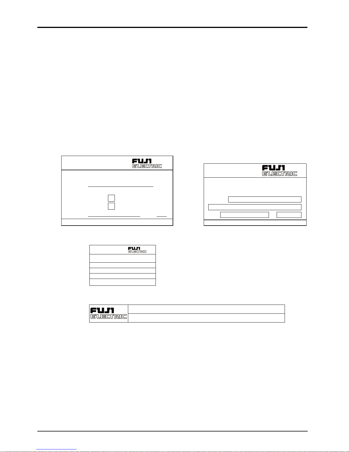
Check on type and specifications
The name of type is inscribed on the specification nameplate. Check the specification nameplate to
make sure that type and specifications are correct as ordered (the nameplate is attached to the side
of the converter, the upper side of the sensor cover (small type, large type) and the side of the frame
(for high temperature).
(1) Specification nameplate
Ultrasonic Flow Meter
Type
Output DC4–20mA
Power Supply
AC100–240V 50/60Hz
DC20–30V
Ser. No.
Fuji Electric Co.,Ltd.
Mfd.
Made in Japan
Ultrasonic
Flow Meter
Type
No.
FL
Fuji Electric Co., Ltd.
T19
Converter
Ultrasonic Flow Meter
Type.
Ser. No.
Mfd.
Fuji Electric Co.,Ltd.
Small type sensor
T
TK773792
Type FLW
M f d. 199 Fujielectric Co., Ltd
Large type sensor
Ser. No. T
High temperature sensor
ii
Page 4

CAUTION ON SAFETY
• The cautionary descriptions listed here contain important information about safety, so they should
always be observed. Those safety precautions are ranked 2 levels; DANGER and CAUTION.
Wrong handling may cause a dangerous situation, in which
DANGER
CAUTION
DANGER
there is a risk of death or heavy injury.
Wrong handling may invite a dangerous situation, in which
there is a possibility of medium-level trouble or slight injury
or only physical damage is predictable.
Caution on installation and wiring
• This unit is not explosion-proof type. Do not use it in a place
with explosive gases to prevent explosion, fire or other serious
accidents.
• The flowmeter should be installed in a place that meets the
• Install the flowmeter according to the instruction manual.
CAUTION
• When installing, make sure that the flowmeter interior is free
• Connect a power source of correct rating to prevent fire acci-
• Before making wiring work, be sure to turn OFF the power
• Use wiring materials of correct rating to prevent fire accidents.
operating conditions shown in this instruction manual.
Installation at an unsuited place may cause electric shock, fire or
incorrect operation.
Improper installation may lead to the cause of fall, trouble or
incorrect operation.
from cable chips and other foreign objects to prevent fire,
trouble, or incorrect operation.
dents.
supply to prevent electric shocks.
iii
Page 5

CONTENTS
PREFACE........................................................................................................................................ i
CAUTION ON SAFETY ...............................................................................................................v
CONTENTS ................................................................................................................................. vii
1. OPERATING PARTS AND THEIR FUNCTIONS............................................................... 1
2. MOUNTING OF CONVERTER............................................................................................ 2
2.1 Selection of mounting place....................................................................................................... 2
2.2 Mounting method....................................................................................................................... 2
2.3 Outline diagram (unit: in.) ......................................................................................................... 3
3. WIRING OF THE CONVERTER.......................................................................................... 4
3.1 Before wiring ............................................................................................................................. 4
3.2 Wiring ........................................................................................................................................ 4
3.3 Treatment of the wiring port ...................................................................................................... 4
3.4 Wiring to terminals .................................................................................................................... 5
4. OPERATION AND WORKS................................................................................................. 6
4.1 Before operation......................................................................................................................... 6
4.2 Power ON and status.................................................................................................................. 7
5. SETTING OF PARAMETERS .............................................................................................. 8
5.1 Outline of operating procedures................................................................................................. 8
5.2 Description of key operation...................................................................................................... 9
5.3 List of setting items.................................................................................................................. 11
5.4 Setting of parameters ............................................................................................................... 12
5.4 (1) Setting of piping specifications ................................................................................... 12
5.4 (2) Setting of analog output range..................................................................................... 14
5.4 (3) Setting of analog output limit ...................................................................................... 16
5.4 (4) Setting of burn-out....................................................................................................... 17
5.4 (5) Setting of damping.......................................................................................................18
5.4 (6) Zero adjustment ........................................................................................................... 19
5.4 (7) Setting of measurement display specifications............................................................ 20
5.4 (8) Low flow output cut .................................................................................................... 21
5.4 (9) Setting of integrated output unit and constant ............................................................. 22
5.4 (10) Setting of integral preset value .................................................................................... 23
5.4 (11) Setting of integration switch ........................................................................................ 24
5.4 (12) Selection of integral pulse output pulse width............................................................. 25
5.4 (13) Setting of measured value high and low limit switch.................................................. 26
5.4 (14) Setting of status output ................................................................................................27
5.4 (15) Calibration of measured value ..................................................................................... 28
5.4 (16) Switch of measurement unit system ............................................................................ 29
iv
Page 6

5.4 (17) Selection of language (English/Japanese) ................................................................... 30
5.4 (18) Analog output check .................................................................................................... 31
5.4 (19) Analog output calibration ............................................................................................ 32
5.4 (20) Status output check ...................................................................................................... 33
5.4 (21) Test mode..................................................................................................................... 34
6. MAINTENANCE AND INSPECTION ............................................................................... 35
6.1 Maintenance............................................................................................................................. 35
6.2 Inspection................................................................................................................................. 35
7. TROUBLESHOOTING........................................................................................................ 36
7.1 How to confirm normal operation............................................................................................ 36
7.1 (1) When checking by LCD indicator ............................................................................... 36
7.1 (2) LCD indication when power turned ON...................................................................... 36
7.1 (3) Detail check for abnormal status ................................................................................. 37
7.2 Faults and remedies.................................................................................................................. 38
7.2 (1) LCD display abnormal................................................................................................. 38
7.2 (2) Key abnormal .............................................................................................................. 38
7.2 (3) Measured value abnormal............................................................................................ 39
7.2 (4) Analog output abnormal .............................................................................................. 42
7.2 (5) Remedy for hardware fault .......................................................................................... 42
8. MOUNTING METHOD....................................................................................................... 43
8.1 Mounting of sensor .................................................................................................................. 43
8.1 (1) Mounting procedure of sensor ..................................................................................... 43
8.1 (2) Selection of mounting place ........................................................................................ 44
8.1 (3) Selection of mounting method..................................................................................... 45
8.1 (4) Processing of sensor mounting surface ....................................................................... 45
8.1 (5) Determination of mounting position (with Z method for large and small types)........ 46
8.1 (6) Cable end treatment ..................................................................................................... 47
8.1 (7) Connection of cable to small type sensor .................................................................... 48
8.1 (8) Mounting of small type sensor on pipe ....................................................................... 49
8.1 (9) Assembling procedure of the sensor............................................................................ 51
8.1 (10) Connection of cable to large type sensor..................................................................... 52
8.1 (11) Mounting of large type sensor on pipe ........................................................................ 53
8.1 (12) Mounting of high temperature sensor on pipe............................................................. 54
APPENDIX 1. SPECIFICATIONS.......................................................................................... A-1
APPENDIX 2. HOW TO MAKE GAUGE PAPER ................................................................ B-1
APPENDIX 3. COMPOSITION OF KEY OPERATION ....................................................... C-1
APPENDIX 4. PIPING DATA ................................................................................................D-1
v
Page 7
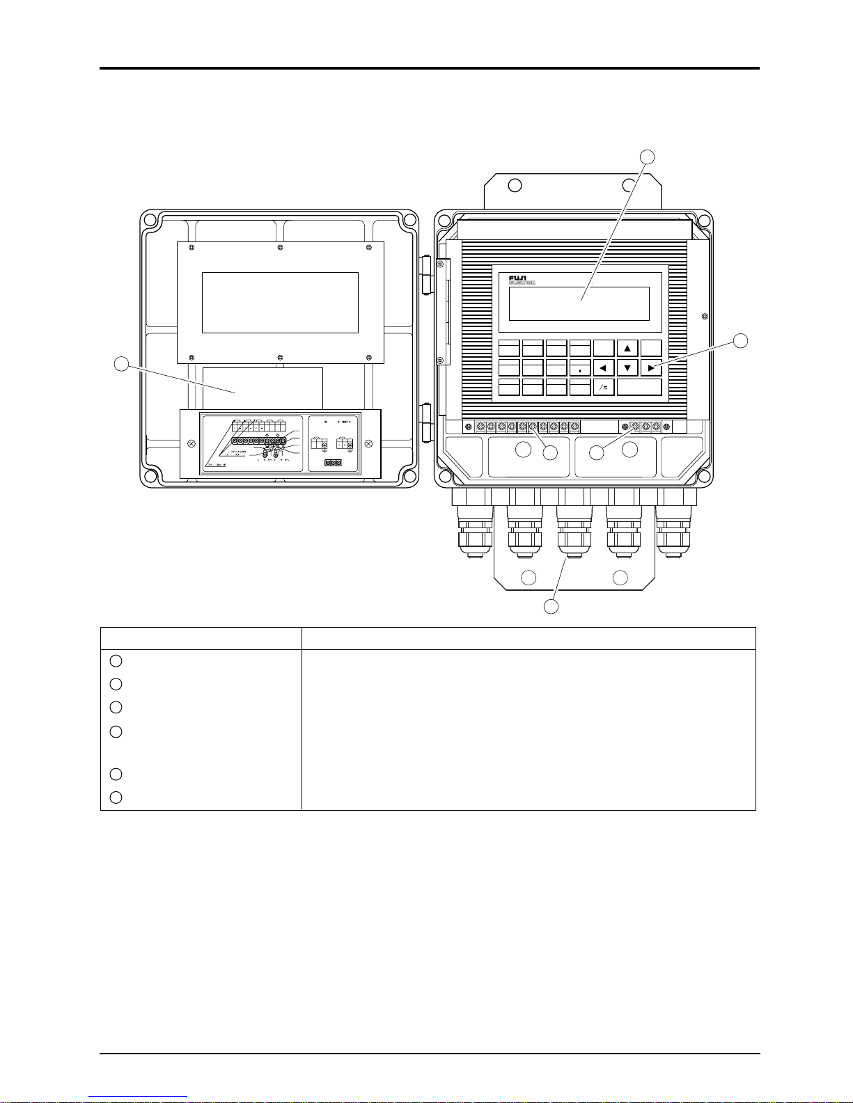
1. OPERATING PARTS AND THEIR FUNCTIONS
The names and funcitons of parts of the converter are as follows.
Names of parts of converter
2
ULTRASONIC FLOW METER
PIPE
OUTPUT DAMP ZERO
7890
FLOW SW
6
TR-out1
TR-out2
I-out
2345
Green
DOWN STRUP STR
6 7
10
Confirm converter power specifications
GND8HF9GND
SH SH
Green
before connecting.
HF
Black
AC100–240V
White
White
Black
To Downstream SensorTo Upstream Sensor
DC20–30V
1
1
23
23
LN
Analog Output
1
Total or Status Output
(Transister)
TOTAL CUT OFF DISP
456
STATUS
CAL SYSTEM CHECK
123
FUNK
54
ESC
ENTER
3
1
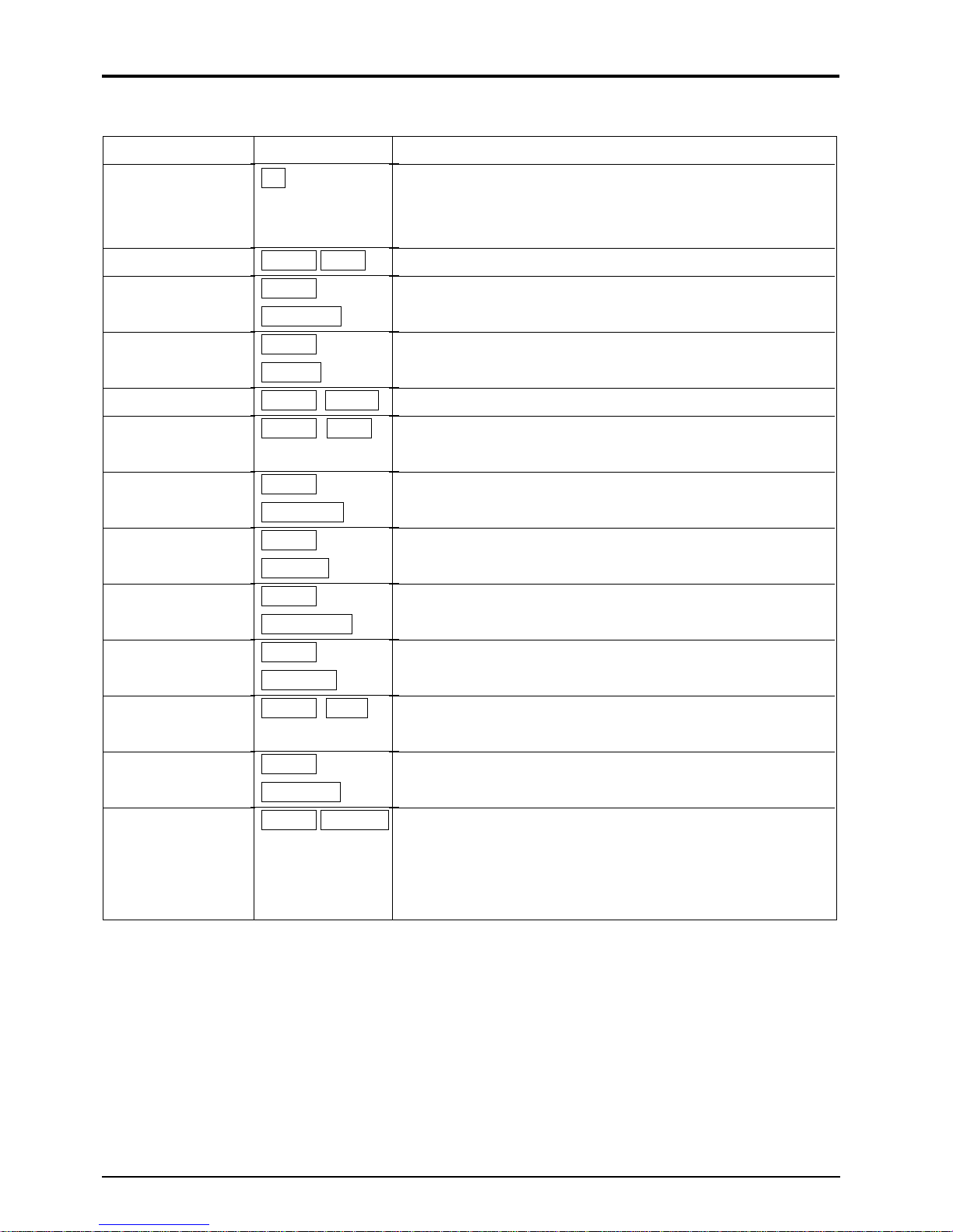
Item Description
1
Wiring port Wiring port for power cable and signal cable
2
Data indicator Liquid crystal indicator for measurement data and set values
3
Key board Used for setting the conditions of adjustments and measurements.
4
Main board terminal block Used for connecting signal cables from sensor.
Used for connection of signal cables for analog output and status output.
5
Power terminal block Used for connecting power cable.
6
Parameter table Used for entering setting data.
1
Page 8
2. MOUNTING OF CONVERTER
2.1 Selection of mounting place
Install the converter at a place satisfying the following conditions.
1. Ambient temperature does not
exceed a range of +14°F to +140°F.
When installing outdoors, attach a
shade or put the converter in an
outdoor panel to protect it from
direct sunlight.
2. Not exposed to moisture.
Even an immersion-proof type is
not protected against entry of water.
Make arrangements so that water
can be drained quickly.
3. Not exposed to dust or corrosive gases.
4. Free from vibrations and shocks.
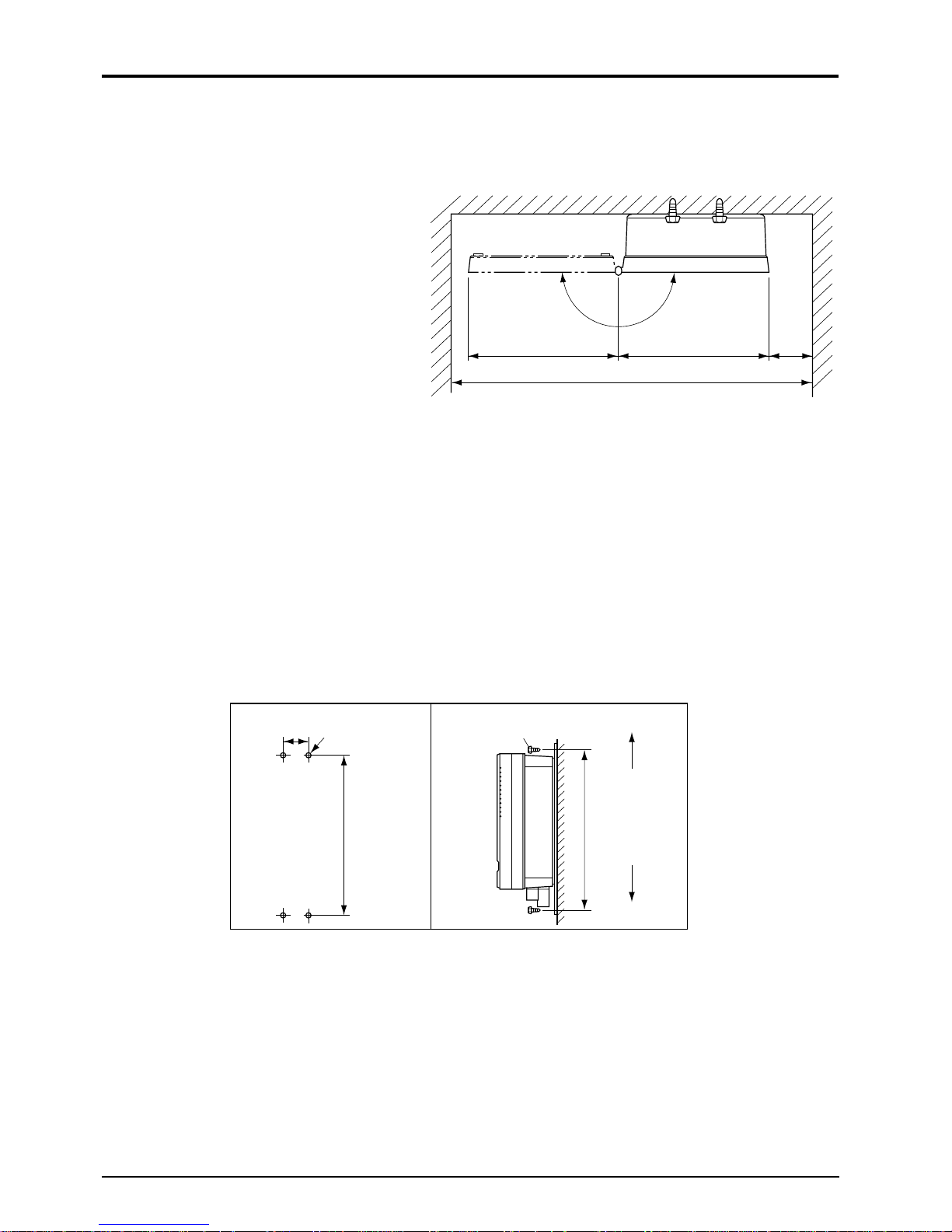
5. Space shown in Fig.2-1 is available for easy inspection and adjustment.
9.45" 9.45"
Fig. 2-1 Installation space (top view)
O
23" or more
N
E
P
4"
or more
2.2 Mounting method
Wall mounting or 2B bypass stand mounting is available for the converter.
For wall mounting, use 4-M8 bolts.
Be sure to mount the converter at correct position as shown in Fig. 2-2.
Make a hole in the wall or the like according to the cutout dimensions shown in the diagram below,
and mount the converter with M8 bolts.
312
12.28"
Top
Bottom
2.83"
4-M8
312
12.28"
Fig. 2-2 Mounting method
M8 bolt
In case of 2B pipe standing type, use U bolts (M8) on the market.
2
Page 9
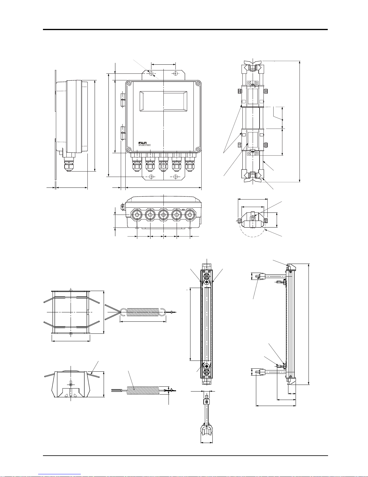
2.3 Outline diagram (unit: in.)
.08-ø.35"
.79"
8.66"
12.28"
10.91"
1/8" 3.75"
.55"
2.83"
9.06"
Sensor
Name plate
3.15"
2.36"
(50A to 250A)
Mounting Dimensions
(0 to 9.85)
Mounting dimensions
(0 to 250)
510
20.08"
72
2.83"
Pipe
Frame end
Ground terminal
3.66"
Sensor unit
1.54"
Converter FLV
104
4.09"
Wire rope
Mounting spring
62
2.44"
1.57" 1.57" 1.57" 1.57"
Scale (inch)
4.49"
Cursor
ø.75"
Sensor FLW1 (small type sensor)
Scale (mm)
Mounting dimensions 0 to 13.0"
Mounting dimensions 0 to 330
ø1.02"
Element holder
1.57"
Saddle
BNC connector
Locking unit
33 33
1.3"
8.07"
Chain & spring
20.87"
1.3"
3.54"
530
Sensor FLW5 (large type sensor)
Sensor FLD32 (high temperature sensor)
2"
3
Page 10

3. WIRING OF THE CONVERTER
3.1 Before wiring
1. For signal cable between the sensor and converter, use double-shielded coaxial cables specified
by Fuji Electric. The coaxial cable should be refrained from connecting midway.
2. The signal cable between the sensor and converter should be run in metalic conduits.
To prevent the effects of induction noise, upstream and downstream signal cables should be wired as
far away from power cable as possible.
3. An output signal cable should use shielded cable as much as possible.
4. To prevent the effects of noise, do not install signal cables together with power cable in the same
duct.
5. A power cable is provided with earth wire, it should be connected to the ground.
6. As this instrument is not equipped with a power switch, be sure to mount a power switch on the
instrument.
7. Wiring ports should be closed when they are not ready to use.
3.2 Wiring
Use the following cables:
• Power cable: 3 or 2 core cabtyre cable,
2
Nominal sectional area : 0.30 in.
Finished outside diameter : ø.43 in.
• Output signal cable: 2 core cable or multi-core cabtyre cable as needed.
Finished outside diameter : ø.43 in.
• Cable between sensor and converter:
Signal cable specified by Code Symbols
(High frequency coaxial cable with characteristic impedance of 50W)
Finished outside diameter : ø.29 in.
or more,
3.3 Treatment of the wiring port
The converter is an immersion-proof type specified by JIS C0920 “Rules for water-proof tests of
electromechanical instruments and wiring materials“. However, if the converter is to be installed in
a pit, air tightness treatment should be provided for the wiring port to prevent possible entry of
moisture, dew condensation or immersion of water.
Waterproof measures should be taken by using waterproof gland or plica tube gland furnished with
this instrument. A gland, which is not ready to be used, should be sealed by supplied cover.
4
Page 11
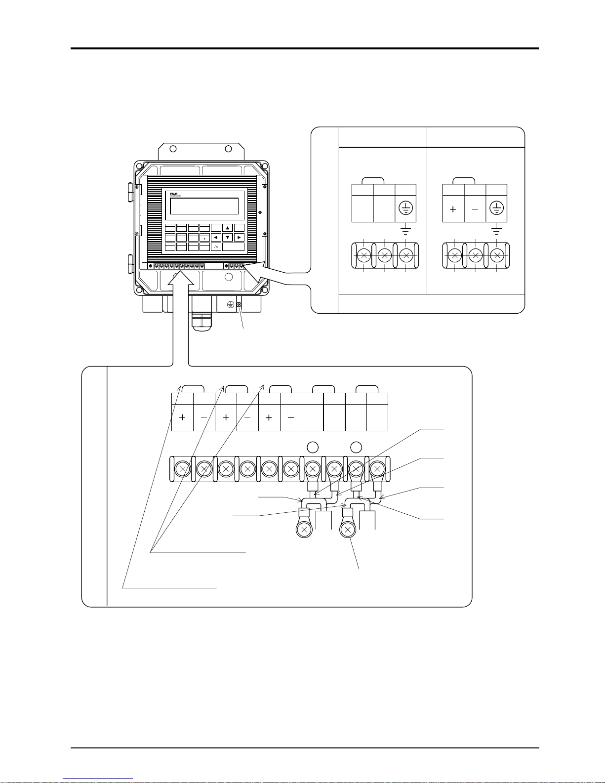
3.4 Wiring to terminals
Cables should be connected as shown in the following diagrams.
ULTRASONIC FLOW METER
PIPE
OUTPUT DAMP ZERO
7890
FLOW SW
TOTAL CUT OFF DISP
456
STATUS
CAL SYSTEM CHECK
123
FUNK
ESC
ENTER
(Note 1) Case grounding terminal
I-out
TR-out TR-out2
1 23456 7
AC power
AC power terminal
1AC23
LN
Power board terminal block
100 to 240V AC
M4 screw
DOW STRUP STR
10
GND8HF9GND
HF
SH SH
DC power
DC power terminal
1DC23
20 to 30V DC
M4 screw(Note 1)
Black
White
Main board teminal block
Total/status output
(transister contact)
Analog output signal
Note 1) Power board terminal block (for power) and case grounding terminals are available for
grounding terminals.
Be sure to earth either of them. (Class D, wiring)
Green
Green
White
Black
To sensor on
the up stream side
To sensor on the
down stream side
5
Page 12

4. OPERATION AND WORKS
4.1 Before operation
Check the following before starting operation.
1. Power
Power check See Item 4.2 (1)
2. Wiring
1) Check of main board terminal block
2) Check of power board terminal block See Item 3.4
3) Check of grounding terminal
3. Piping
1) Check that a piping is filled with fluid.
2) Check that there is no problem when water stops or flows.
}
6
Page 13
4.2 Power ON and status
1. Power specification
1) AC power
Use power supply of 100 to 240VAC ±10% (50/60 Hz).
2) DC power
A power of 20V to 30V DC is available.
2. Power ON
When the instrument is turned on, the following data are displayed on the LCD after making a
self-check of the devices.
The numerical values and symbols being displayed are as described below:
FLV-2SYSTEM
Ver FL.V2
BACK PU MEMO YR
LO DI NGA
Stab l iityWit!a
Measuring screen
000.0m/ Rs
.0000m/s3
Flow display (See Item 5.4 (7))
Flow direction
If the upstream and downstream sensors are connected reversely,
a symbol "—" appears on the LCD.
Load parameters and data from
non-volatile memory
Preparation to be taken until the measuring
conditions are met.
Display of integration, flow velocity and range %
(See Item 5.4 (7))
Status display (See Item 7.1. (1))
7
Page 14
5. SETTING OF PARAMETERS
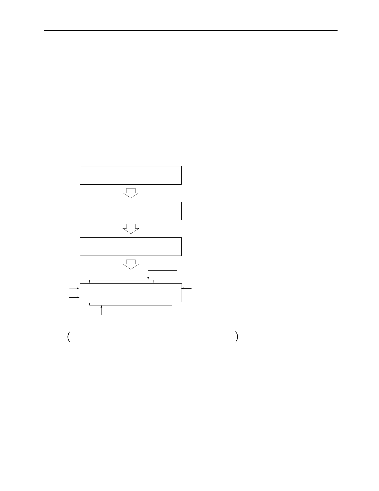
5.1 Outline of operating procedures
Proceed to the following procedure before starting measurements.
Chapter 3
Chapter 4 Power ON
5.4 (1)
Chapter 8 Installation of sensor
5.4 (6)
Output specification setting
System setting
Integration specification setting
Flow switch setting
Measuring display specification setting
Damping setting
Low flow cut setting
Output compensation setting
Status output setting
Installation and wiring
of converter
Check of piping
specification
OK
Measurement error
Measurement OK
Zero adjustment
NG
5.4 (1)
Chapter 7 Troubleshooting
Input of piping
specification
Measurement
Chapter 6 Maintenance and check
8
Page 15

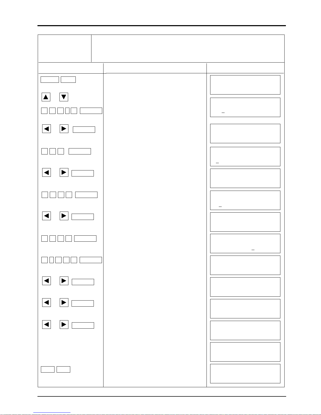
5.2 Description of key operation
Note) When adjustment is performed or setting is changed in this Chapter, be sure to enter
parameters in the list attached to the converter.
Pressing the FUNC key enables you to perform the functions shown on the upper side of the
ten-keys.
ULTRASONIC FLOW METER
PIPE
OUTPUT DAMP ZERO
7890
FLOW SW
STATUS
TOTAL CUT OFF DISP
456
CAL SYSTEM CHECK
123
Description of key (1/2)
FUNC
ESC
ENTER
Name
Ten-keys
ENTER
,
,
ESCAPE (Stop)
Key display
0 to 9 , • , ±
ENTER
,
,
ESC
Description
To enter data and numeric values of piping specifications.
By pressing this key, numeric data and selected interactive items are set. In the interactive mode, questions are
displayed.
To move the cursor to correct numeric values.
Pressing the
key allows the cursor to be moved the
left.
Pressing the key allows the cursor to be moved the
right.
Select the menu item display in an interactive message.
Pressing the
key allows the menu page to advance.
Pressing the key allows the menu page return.
To stop interactive operation.
FUNC. (Function)
FUNC
To perform the function inscribed on each ten-key.
9
Page 16
Description of key (2/2)
Name
/pi
PIPE (Pipe)
OUTPUT
(Analog output)
DAMPING
(Damping)
ZERO (Zero)
DISPLAY
(Display panel)
CUT OFF
(Low flow cut)
TOTAL
(Integration)
FLOW SW
Key display
/pi
FUNC PIPE
FUNC
OUTPUT
FUNC
DAMP
FUNC ZERO
FUNC DISP
FUNC
CUT OFF
FUNC
TOTAL
FUNC
Description
By pressing this key, the circumstance of pipe, which has
been entered, is converted into the outside diameter.
(valid only when setting the outside diameter of pipe)
To enter the size and material of the sensor piping.
To set the condition of an analog output
(units, range, limit, burn-out)
To set the damping.
To use when zero adjustment is performed.
Keys used to change items or unit system on the measurement display screen.
To set the low flow cut.
To set condition required for integration of flow rate.
(units, constant, preset value, integral switch, pulse width)
To set the measured high/low value switch
(Flow switch)
STATUS
(Status)
CAL.
(Calibration)
SYSTEM
(System)
CHECK (Check)
FLOW SW
FUNC
STATUS
FUNC CAL
FUNC
SYSTEM
FUNC CHECK
To set condition of status output (integration pulse, measuring status)
To compensate indication values of zero point and 100%
point. (Current output is effected)
To switch the measuring unit system and language, or
confirm or calibrate analog output.
To display an error message and countermeasures when
an error appears.
(An error message is displayed on the upper-right of the
LCD.)
10
Page 17
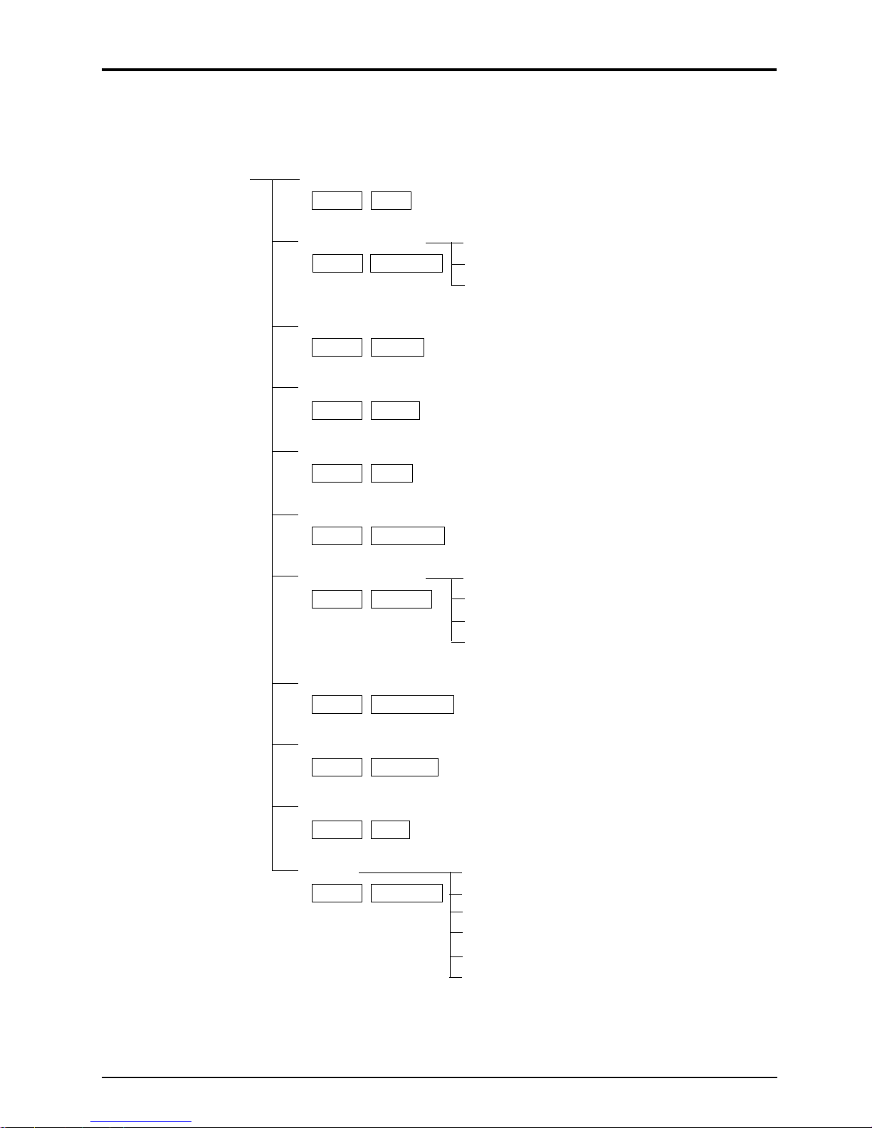
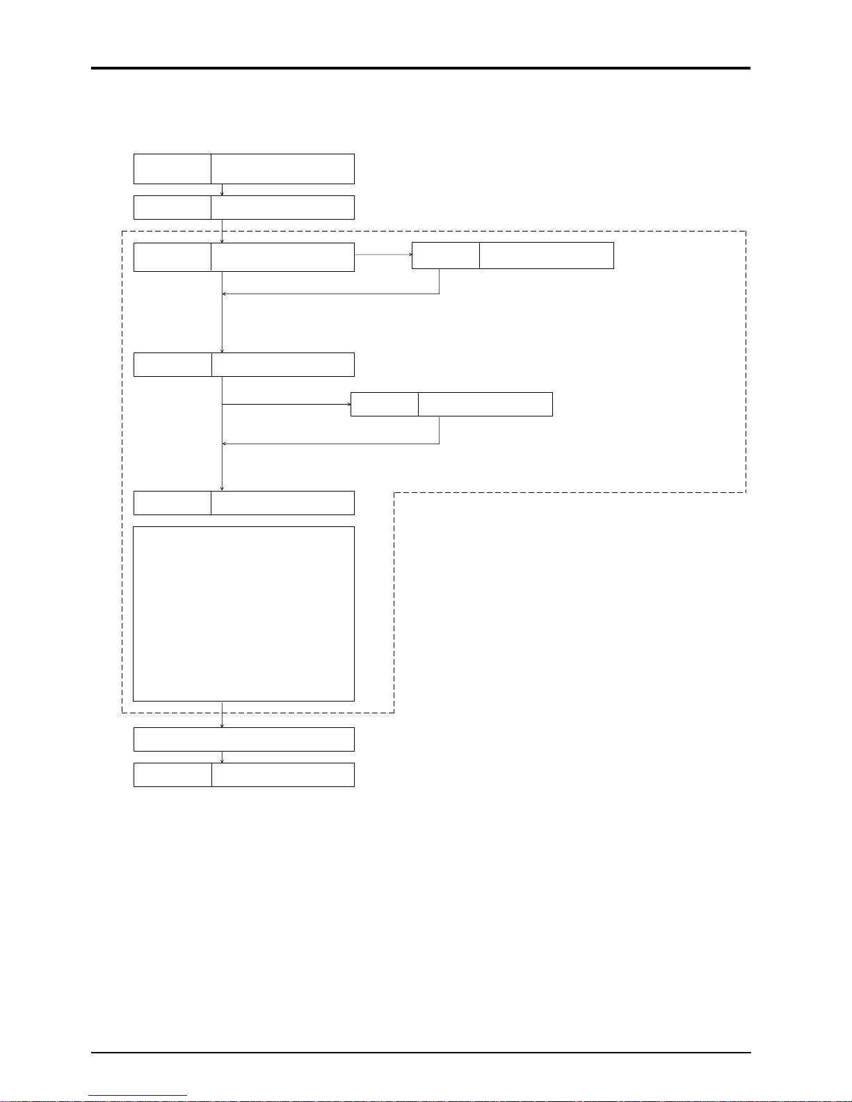
5.3 List of setting items
Measurement screen Piping specifications-----------------------------------See Item 5.4 (1)
( FUNC PIPE )
Setting of output Range------------------------See Item 5.4 (2)
( FUNC OUTPUT ) Output limit-----------------See Item 5.4 (3)
Burn-out--------------------- See Item 5.4 (4)
Damping-------------------------------------------------See Item 5.4 (5)
( FUNC DAMP )
Zero adjustment ----------------------------------------See Item 5.4 (6)
( FUNC ZERO )
Display setting------------------------------------------See Item 5.4 (7)
( FUNC DISP )
Low flow cut--------------------------------------------See Item 5.4 (8)
( FUNC CUT OFF )
Integration
Integration unit and constant -----
See Item 5.4 (9)
( FUNC TOTAL ) Integral preset -------------- See Item 5.4 (10)
Integral switch -------------See Item 5.4 (11)
Integral pulse width -------See Item 5.4 (12)
Flow switch ---------------------------------------------See Item 5.4 (13)
( FUNC FLOW SW )
Status output --------------------------------------------See Item 5.4 (14)
( FUNC STATUS )
Output compensation ----------------------------------See Item 5.4 (15)
( FUNC CAL )
System Measuring unit ------------ See Item 5.4 (16)
( FUNC SYSTEM ) Switch of language ------- See Item 5.4 (17)
Confirmation analog outpu
Analog output calibration -----
t---
See Item 5.4 (18)
See Item 5.4 (19)
Status output check ------- See Item 5.4 (20)
Test mode ------------------ See Iitem 5.4 (21)
11
Page 18

5.4 Setting of parameters
• Units are displayed in metric system.
5.4 (1) Setting of piping specifications
Description
Set the data of pipe required for measurement. The mounting dimension of the sensor is
automatically calculated. Data of each item should be entered according to the display.
Item
Outside diameter of pipe
Material of pipe
Numeric value
Selectable
Entry
Range or menu
2 in. to 236 in.
CARBON STEEL, STAINLESS STEEL, PVC,
COPPER, CAST IRON, ALUMINUM, FRP, ASBESTOS, DUCTILE IRON, PEEK, PVDF, ACRYLIC,
OTHERS*1
Pipe wall thickness
Lining (with/without)
and material
Type of fluid
Dynamic viscosity
Numeric value
Selectable
Selectable
Numeric value
0.0039 in. to 3.937 in.
NO LINING, TAR EPOXY, MORTAR, RUBBER,
TEFLON, PYREX GLASS, OTHERS *1
WATER, SEAWATER, OTHERS *1
-
0.001E
19.68 ft.2/s to 999.999E-19.68 ft.2/s *2
coefficient of fluid
Mounting method of
Selectable
V METHOD, Z METHOD
sensor
Type of sensor
Transmission voltage of
Selectable
Selectable
FLW12, FLW41, FLW50
1 TIME, 2 TIME, 4 TIME, 8 TIME
sensor
*1) Selection of “OTHERS”
Materials of piping and lining should be selected within the range of 3281 to 12,139 ft./sec.
of sound velocity and 1640 to 8202 ft./sec. of flow velocity (see Appendix).
*2) Dynamic viscosity coefficient is expressed in water (68°F: 1.004E
When more accurate data need be obtained or fluid other than water is selected, enter an
appropriate data as needed from Appendix.
-
19.68 ft.2/s)
12
Page 19
Operation (example) Outside diameter:114.3mm, pipe material:carbon steel, thickness:4.5mm,
lining material:mortar, thickness:1.25mm, fluid:heavy water, sound velocity:
1388m/s, dynamic viscosity coefficient: 1.129 x 10
method:V method, type: FLW12, Transmission voltage:8 times
-6m2
/s, sensor mounting
Key operation
FUNC PIPE
or
1 1 4 . 3 , ENTER
or , ENTER
4 . 5 , ENTER
or , ENTER
1 . 2 5 , ENTER
or , ENTER
Description
The sensor mounting dimension is
displayed.
Select “OUTER DIAMETER”.
Enter “114.3” with ten keys.
Select “CARBON STEEL”.
Enter “4.5” with ten keys.
Select :MORTAR”.
Enter “1.25” with ten keys.
Select “OTHERS”.
Display
SENSOR SPACING
0.00 mm V
OUTER DIAMETER
3mm
114.
PIPE MATERIAL
CARBON STEEL
WALL THICKNESS
5mm
4.
LINING MATERIAL
MORTAR
LINING THICKNESS
5mm
1.2
KIND OF FLUID
OTHERS
1
3 8 8 , ENTER
1 . 1 2 9 , ENTER
or , ENTER
or , ENTER
Note 3
or , ENTER
ESC ESC
Enter “1388” with ten keys.
Enter “1.129” with ten keys.
Select “V METHOD”.
Select “FLW12”.
SELECT “8 TIME”.
The sonsor mounting dimension is
displayed.
Press the key twice.
FLUID S.V.
8 m/s
138
VISCOSITY
1.129E – 6 m2/s
SENSOR MOUNTING
V METHOD
SENSOR TYPE
FLW12
TRANS. VOLTAGE
8 TIME
SENSOR SPACING
80.56 mm V
(Measurement display)
Note 3) When selecting the transmission voltage, generally choose “4 TIME”.
13
Page 20
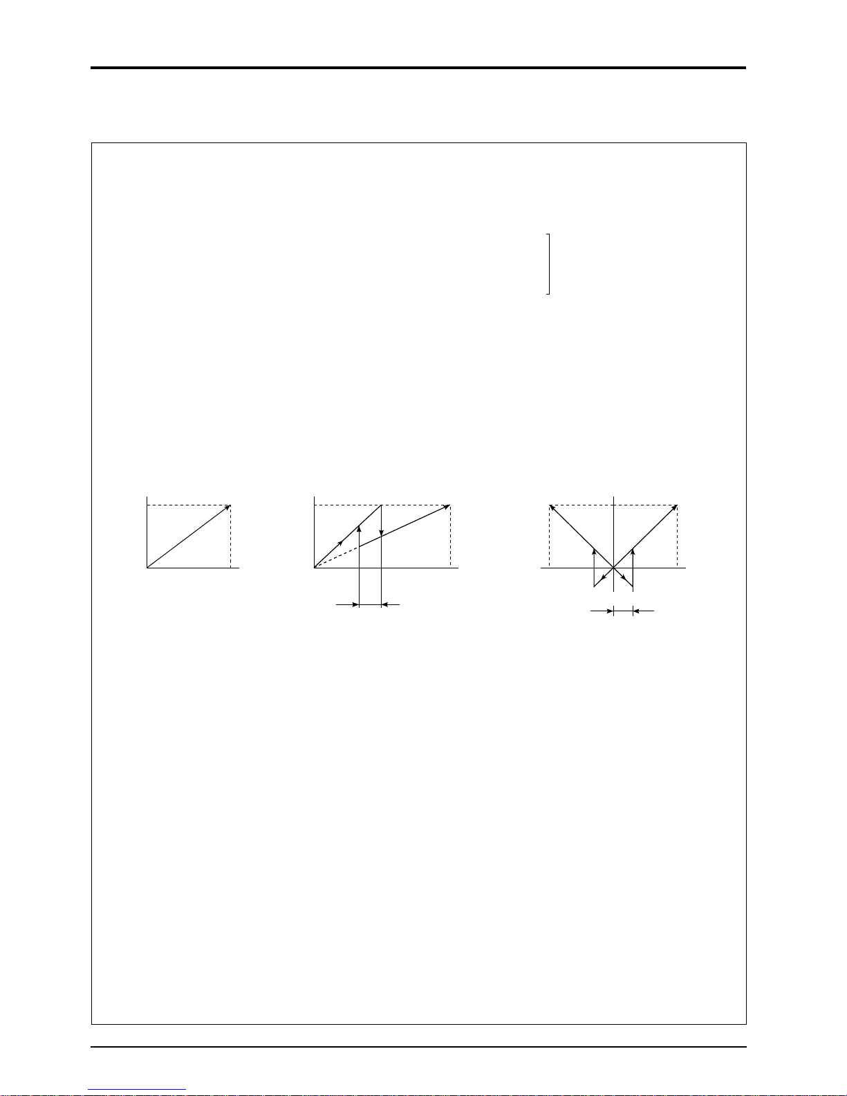
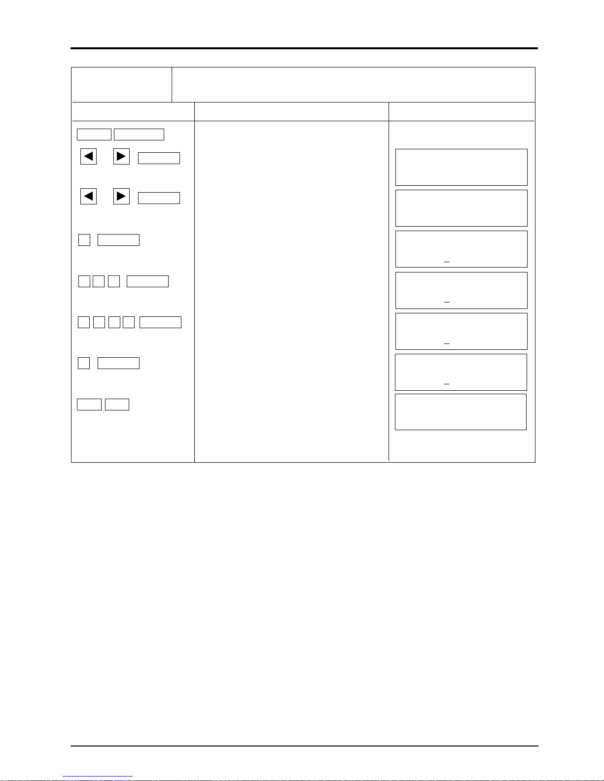
5.4 (2) Setting of analog output range
Description
An analog output range is set to provide an output of 4 to 20mA in the specified range of
measured values (flow rate or flow velocity).
[Measurement items]
1. Selection of range unit ............ m/s
Note 1)
l/s, l/m l/h, Ml/d
3
/s, m3/m, m3/h, Mm3/d
m
BBL/s, BBL/m, BBL/h, MBBL/d
2. Selection of range type
• SINGLE RANGE: Single range
• AUTO 2 RANGES: Auto 2 ranges
• BI-DIR RANGE: Auto forward/reverse range
Choose any of
the unit: METRIC system
Single range
Analog output
20mA
4mA
BASE
SCALE
FULL
SCALE
3. Setting of range
• BASE SCALE: Set flow rate value or flow velocity value for 4mA output.
• FULL SCALE: Set flow rate value or flow velocity value for 20mA output.
4. Setting of hysteresis
When selecting “AUTO 2 RANGES” or “BI-DIR.RANGE” from the type of range,
hysteresis is selectable.
Set the hysteresis within the range of 0 to 20% of full scale.
• In case of auto 2-range: Hysteresis of span size of full-scale 1 or full-scale 2, whichever
• In case of forward/reverse range: Hysteresis of span in action range
Note 1) Flow units of low flow cut, flow switch and output compensation flow units
Analog output
20mA
Flow rate
4mA
BASE
SCALE
Auto 2 range
FULL
SCALE1
Hysteresis setting
Flow rate
FULL
SCALE2
Auto range, forward/reverse range
Analog output
20mA
4mA
FULL
SCALE2
BASE SCALE
Flow velocity value should be set within the range of 0 to ±32m/s.
Flow velocity value should be set within the range of ±0.3 to ±32m/s.
is smaller
are changed with the selection of the range unit.
FULL
SCALE1
Hysteresis setting
14
Page 21
Operation (example) When setting the base scale to 0m3/h, full scale 1 to 100m3/h, full scale 2 to –
100m3/h and hysteresis to 5% in the forward/reverse range.
Key operation
FUNC OUTPUT
or , ENTER
or , ENTER
0 , ENTER
1 0 0 , ENTER
± 1 0 0 , ENTER
5 , ENTER
Description
Select “m3/h”.
Select “Forward/reverse range”.
Enter “0” with ten keys.
Enter “100” with ten keys.
Enter “–100” with ten keys.
Enter “5” with ten keys.
Display
RANGE UNIT
RANGE TYPE
BI-DIR. RANGE
BASE SCALE
0 m3/h
FULL SCALE 1
0 m3/h
10
FULL SCALE 2
0 m3/h
–10
RANGE HYSTERESIS
5%
m3/h
ESC ESC
Press the key twice.
(Measurement display)
15
Page 22
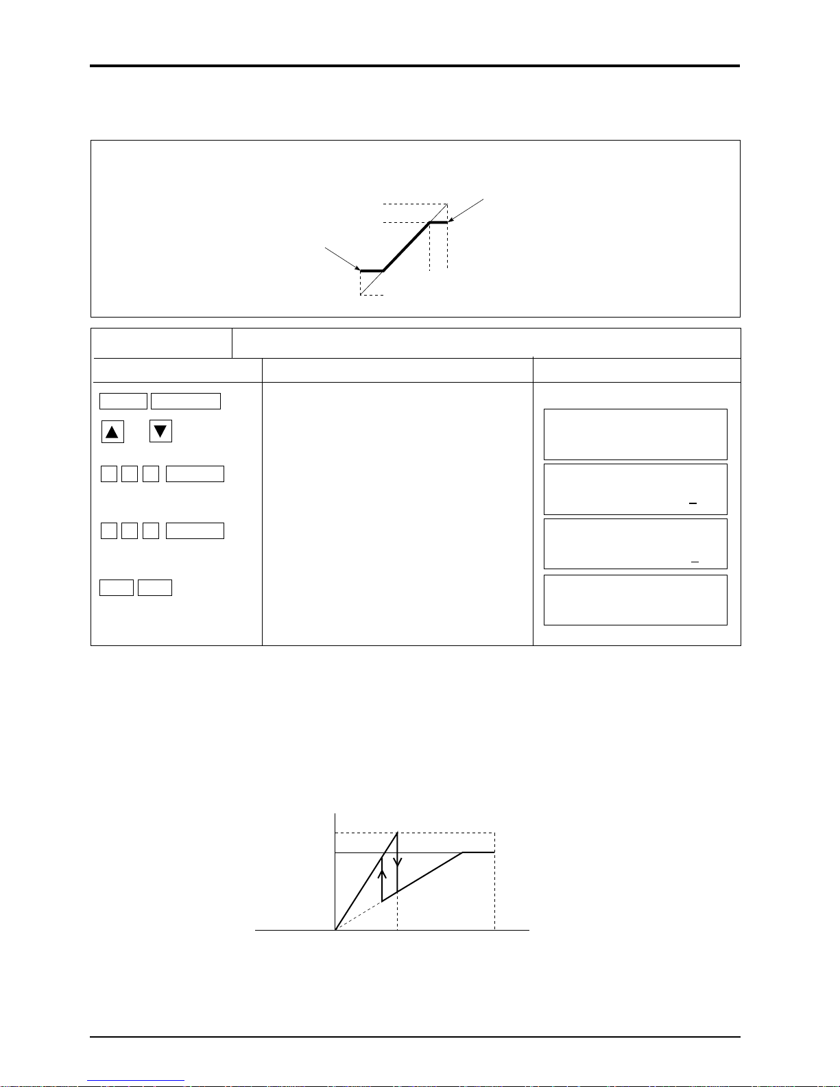
5.4 (3) Setting of analog output limit
Description
Set the high/low limits within the range of analog output of 0.8 to 23.2mA (
-
20 to 120%).
Low limit
Analog output
23.2mA
20mA
4mA
-20%
0% 100% 120%
0.8mA
High limit
Flow rate
Operation (example) Low limit : -10% (2.4mA), high limit : 110% (21.6mA)
Key operation
Description
FUNC OUTPUT
or
± 1 0 , ENTER
1 1 0 , ENTER
Select “Output limitter”.
Enter “–10”with ten keys.
Enter “110” with ten keys.
OUTPUT LIMIT
LOW – 20 %
OUTPUT LIMIT
LOW – 1
OUTPUT LIMIT
HIGH 11
Display
0 %
0 %
ESC ESC
• In case of auto 2-range :
• In case of forward/reverse range :
Press the key twice.
(Measurement display)
Low limit is limited to the small range, and High limit is limited to the large range.
The low/high limits are limited to the range of action.
(100%)20mA
(0%) 4mA
Base
scale
Auto 2 range
Full
scale 1
High limit
Full
scale 2
16
Page 23
5.4 (4) Setting of burn-out
Description
When the pipe is empty of fluid or when air bubbles are contained in fluid, the flow rate can
not be measured correctly. In such a case, the analog output needs to be set to “HOLD”,
“HIGH” limit or “LOW” limit. A burnout timer is used to set the time needed for burnout.
(Setting items)
• HOLD : Measured value is held
• HIGH : 120%t output (23.2mA) is obtained.
-
• LOW :
• Zero : 0 % output (4.0mA) is obtained.
• NOT USED : Not used.
• Liquid crystal display : Measured value is held.
• Integrated pulse output : Output stops Note)
• Internal integration : Integration stops Note)
Note) Integrated pulse output and internal integration is integrated until the burnout timer is
energized.
20% output (0.8mA) is obtained.
Operation (example) When setting the burnout to the “LOW” limit and burnout timer to 15
seconds.
Key operation
Description
Display
FUNC OUTPUT
or
or , ENTER
1 5 , ENTER
ESC ESC
Select “Burn-out”.
Select “Low limit”.
Enter “15” with ten keys.
Press the key twice.
OUTPUT BURNOUT
NOT USED
OUTPUT BURNOUT
BURNOUT TIMER
(Measurement display)
LOWER
15 sec
17
Page 24
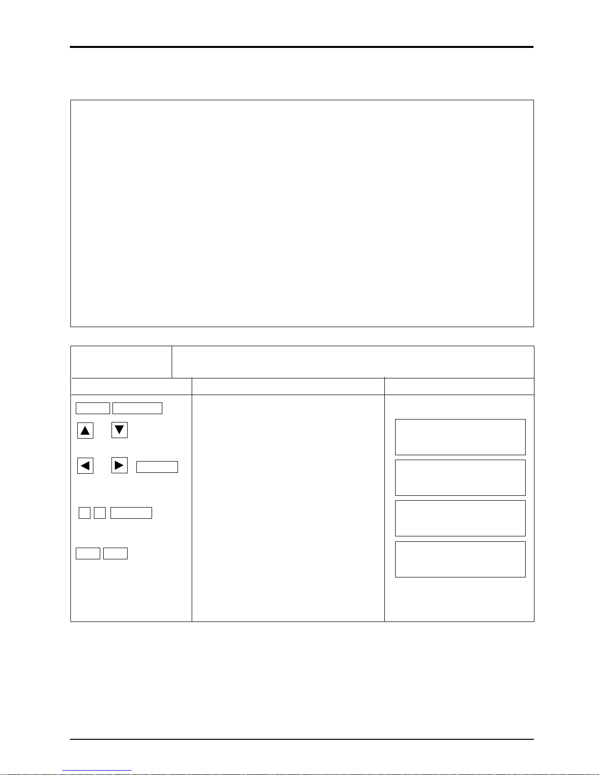
5.4 (5) Setting of damping
Description
Damping is used to suppress fluctuation of measured values.
The set value is a time constant (about 63% response time). (Setting range : 0 to 100 sec)
63%
Flow rate
Response time
Time
Unless otherwise specified in the order sheet, the setting time of damping is adjusted to 5 sec.
Operation (example) Change of set value to 20 sec.
Key operation
Description
FUNC DAMP
2 0 , ENTER
Enter “20” with ten keys.
DAMPING
(Measurement display)
Display
0 sec
2
18
Page 25

5.4 (6) Zero adjustment
Description
Zero point of measured value is adjusted.
(Setting items)
• ZERO POINT ADJUST : Stop the flow of fluid and adjust zero point.
The zero pont is the state of measurement at set point.
• ZERO POINT CLEAR : This setting is used when fluid will not stop flowing.
Adjusted zero point is cleared.
Operation (example) Zero point adjustment when fluid is in stop mode.
Key operation
Description
FUNC ZERO
Display
or , ENTER
Select “Zero point adjustment”.
ZERO MODE
SET ZERO
(Measurement display)
19
Page 26

5.4 (7) Setting of measurement display specifications
Description
Select measured value from the following.
1. Setting of measurement display 1st line
Select any one from the following 7 types for the 1st line display.
F : TOTAL : Forward integral value
R : TOTAL : Reverse integral value
TOTAL DIFF : Forward/reverse difference between integral values
F : TOTAL PULSE : Forward integral pulse counter
R : TOTAL PULSE : Reverse integral pulse counter
FLOW VELOCITY : Instantaneous flow velocity [m/s]
RANGE % : Ratio of analog output to range
2. Setting of decimal measurement display on 2nd line
On the second display is instantaneous flow rate displayed.
Select one from the following 12 units of flow rate.
l/s, l/m l/h, Ml/d,
BBL/s, BBL/m, BBL/h, MBBL/d
3. Setting of decimal point position of instantaneous flow rate display
Setting of digit display after the decimal point is available.
Select any one from the following.
Position of decimal point (digit) Range of data display
00000000. : -99999999. to 0. to 99999999.
0000000.0 : -9999999.9 to 0.0 to 9999999.9
000000.00 : -999999.99 to 0.00 to 999999.99
00000.000 : -99999.999 to 0.000 to 99999.999
0000.0000 : -9999.9999 to 0.0000 to 9999.9999
000.00000 : -999.99999 to 0.00000 to 999.99999
00.000000 : -99.999999 to 0.000000 to 99.999999
0.0000000 : -9.9999999 to 0.0000000 to 9.9999999
m3/s, m3/m, m3/h, Mm3/d
(metric system)
}
Display of integral value
1. Display of forward/reverse integral values
#
2. Display of forward/reverse difference between integral values
Difference of integrated value = forward integral value
Note : If any of integral values in the forward and reverse directions exceeds the over
flow mark, ####### is displayed.
Overflow mark
When the integral value exceeds the overflow mark.
Overflow times
0 to 9, # (exceeding 9)
Integral value
0 to 9999999
-
reverse integral value.
20
Page 27

Operation (example) Display instantaneous flow velocity and instantaneous flow unit in m3/h, and
instantanous flow rate in 3 digits after decimal point.
Key operation
Description
Display
FUNC DISP
or , ENTER
or , ENTER
or , ENTER
Select “Flow velocity”.
Select :m
Select “00000.000”.
ESC ESC
5.4 (8) Low flow output cut
Description
A low flow output can be cut.
This flowmeter will display the flow rate, when the fluid in the piping is moving with the
valve closed due to a convection current. The cutting point should be set as needed.
(Setting range : 0 to 16.4 ft./s in terms of flow velocity value)
3
/h”.
1: DISPLAY KIND
VELOCITY
2: FLOW UNIT
m3/h
2: DECIMAL POINT
00000.000 m3/h
(Measurement display)
Outlet
Flow rate
Cutting set value
Operation (example) Setting of cutting point to 0.05m/s.
Key operation
Description
FUNC CUT OFF
0 . 0 5 , ENTER
Enter “0.05” with ten keys.
Display
CUT OFF
0.05 m/s
(Measurement display)
21
Page 28

5.4 (9) Setting of integrated output unit and constant
Description
Integrated output unit is set to integrate measurement value (flow rate)
Just after setting of measured value is completed, the pulse counter begins integration by
clearing the previous integrated value.
1. Integrated unit.………Select one of the following 8 kinds of integral units.
m3, km3, Mm3, mBBL, BBL, kBBL (metric system)
ml, l,
Note : When changing the integrated unit, integral constant value and integral preset
value are cleared.
2. Integral constant
When the flow rate reaches the value set by the integral constant, integral pulse value is
displayed on the measurement screen, and the integral pulse counter provides an output of 1
pulse.
Setting range : 0 to 9999999
Operation (example) Integrated output of 100m
Key operation
Description
FUNC TOTAL
or , ENTER
or , ENTER
1 0 0 , ENTER
ESC
or , ENTER
ESC ESC
Display “TOTAL MODE”.
Select “m3”.
Enter “100” with ten keys.
Display “TOTAL MODE”.
Select “START”.
Press the key twice.
3
Display
TOTAL MODE
TOTAL STOP
TOTAL UNIT
m3
TOTAL RATE
0 m3
10
TOTAL MODE
TOTAL STOP
TOTAL MODE
TOTAL RUN
(Measurement display)
Integral mode
Stop: Integration is stopped.
Start: Integration is started (integral parameter can not be changed at a time of start).
Reset: Integral value is set to the integral preset value, and integration is stopped.
When the flowmeter is restored from power interruption, it will be operated in the integral mode that
was set before power interruption.
[Note : If measurement is abnormal, refer to burnout setting for integration.]
22
Page 29

5.4 (10) Setting of integral preset value
Description
Set integrated preset value
F: TOTAL PRESET: Forward integral preset value
R: TOTAL PRESET: Reverse integral preset value
Setting range: 0 to 9999999
Addition
Preset value
0
Time
Note: In case of setting, please keep “TOTAL MODE” suspended.
Operation (example) Forward direction : 1000m3, reverse direction : 2000m
Key operation
Description
FUNC TOTAL
or
1 0 0 0 , ENTER
ENTER
2 0 0 0 , ENTER
Select “F: TOTAL PRESET”.
Enter “1000” with ten keys.
Select “R: TOTAL PRESET”.
Enter “2000” with ten keys.
3
Display
F:TOTAL PRESET
F:TOTAL PRESET
R:TOTAL PRESET
R:TOTAL PRESET
100
200
0 m3
0 m3
0 m3
0 m3
ESC ESC
Press the key twice.
(Measurement display)
23
Page 30

5.4 (11) Setting of integration switch
Description
When an integral value exceeds the set value, the status output is provided.
F: TOTAL SW: Forward integration switch
R: TOTAL SW: Reverse integration switch
Setting range: 0 to 9999999
Note) When setting the status output, integration switch is valid only
when “F: TOTAL SW” or “R: TOTAL SW” is set.
Integration
Setting value
OFF
ON
Contact output
Note: In case of setting, please keep “TOTAL MODE” suspended.
Operation (example) Set value of forward integration switch :50000m
Key operation
Description
FUNC TOTAL
or
5 0 0 0 0 , ENTER
ESC ESC
Select “TOTAL SW”.
Enter “50000” with ten keys.
Press the key twice.
3
Display
F: TOTAL SW
F: TOTAL SW
(Measurement display)
5000
0 m3
0 m3
24
Page 31

5.4 (12) Selection of integral pulse output pulse width
Description
The following 2 types can be selected according to the counter connected.
When setting status output, set the pulse width to use “F:TOTAL” or “R:TOTAL”.
• 50msec
• 100msec
Note: In case of setting, please keep “TOTAL MODE” suspended.
Operation (example) Pulse width: 100msec.
Key operation
Description
FUNC TOTAL
Display
or
or , ENTER
Select “Pulse width”.
Select “100msec”.
PULSE WIDTH
50 msec
PULSE WIDTH
100 msec
(Measurement display)
25
Page 32

5.4 (13) Setting of measured value high and low limit switch
Description
1. Set high limit and low limit of switching point when using high limit flow or low limit flow
to set the status output.
Setting range : 0 to ±105 ft./s of flow velocity
[Relation between status output and set value]
• High limit setting and high limit flow • Low limit setting and low limit flow
–105 ft./s –105 ft./s
ON
0 ft./s 0 ft./s
OFF OFF
High limit
set value
105 ft./s
ON
Hysteresis
ON
OFF OFF
ON
Low limit
set value
2. Setting of hysteresis
Switching hysteresis can be held in the following range.
Set hysteresis within 0 to 20% of the analog output range full scale (with auto 2 range, and
forward and reverse auto range, effective for full scale 1 and 2, whichever small).
Operation (example) Low limit flow velocity: 3.5m/s, high limit flow velocity value: 12m/s,
hysteresis : 5%
Key operation
Description
Display
FUNC FLOW SW
3 . 5 , ENTER
Enter “3.5” with ten keys.
FLOW SW LOW
105 ft./s
Hysteresis
5 m/s
3.
1 2 , ENTER
5 , ENTER
Enter “12” with ten keys.
Enter “5” with ten keys.
26
FLOW SW HIGH
FLOW SW HYS.
(Measurement display)
2 m/s
1
5 %
Page 33

5.4 (14) Setting of status output
Description
• When the status of setting or integral pulse is outputted, the contents of output is set.
1. NOT USED : No output
2. SIGNAL ERROR : ON at abnormal measurement
3. F: TOTAL PULSE : Forward flow integral pulse
4. R: TOTAL PULSE : Reverse flow integral pulse
5. FLOW SW HIGH : ON when the flow rate is over the high limit set by flow switch.
6. FLOW SW LOW : ON when the flow rate is below the low low limit set by
7. F: TOTAL ALARM : ON when the flow rate is over the forward flow integration
8. R: TOTAL ALARM : ON when the flow rate is below the reverse flow integra-
9. F: TOTAL OVERFLOW : ON when the forward flow integral value overflows.
10. R: TOTAL OVERFLOW : ON when reverse flow integral value overflows.
11. FULL SCALE 2 : ON at FULL SCALE 2 RANGE in analog output range status.
12. R: FLOW DIRECTION : ON when the flow direction is reverse.
13. RANGE OVER : ON when the set value of the output span exceeds the range
14. BACK UP ABNORMAL : ON when the backup non-volatile memory is abnormal.
• Setting of status output pulse mode
Normal: effective when status output is ON.
Spot: effective when status output is OFF.
flow switch.
switch.
tion switch.
-
10 to 110%, or integral pulse output exceeds 5 pulse/
of
sec.
Operation (example) When setting the forward integral pulse and contact output in the normal
mode.
Key operation
FUNC STATUS
or , ENTER
or , ENTER
or , ENTER
ESC
Description
Select “CHANNEL 1”.
Select “F: TOTAL”.
Select “Normal”.
(Continued on next page)
27
Display
STATUS CHANEL
CHANNEL 1
STATUS SEL : CH1
F : TOTAL
STATUS MODE : CH1
NORMAL
Page 34

Operation (example) When setting the forward integral pulse and contact output in the normal mode.
Key operation
or , ENTER
or , ENTER
or , ENTER
ESC ESC
5.4 (15) Calibration of measured value
Description
Measured value (zero and span points) can be calibrated, if required.
Zero point and span point can be calibrated.
Calibration range: Zero point: ±16.4 ft./s of flow velocity
Measured value and analog output value are calculated by the following formula.
Output =
Select “CHANNEL 2”.
Select “F: TOTAL ALARM”.
Select “SPOT”.
Press the key twice.
Span: ±200%
Measured value ´ [span set value %]
Output
Description
100
Output
100%
Display
STATUS CHANEL
CHANNEL 2
STATUS SEL : CH2
F : TOTAL ALARM
STATUS MODE : CH2
SPOT
(Measurement display)
+ Zero point
0
Movement of zero point
Operation (example) Calibration of zero point to – 0.5m/s and span point 105%
Key operation
FUNC CAL
± 0 . 5 , ENTER
1 0 5 , ENTER
ESC ESC
Enter “– 0.5” with ten keys.
Enter “105” with ten keys.
Press the key twice.
Flow Flow
0
Movement of span
Description
CALIBRATION ZERO
CALIBRATION SPAN
28
Display
–0.
5 m/s
5%
10
(Measurement display)
Page 35

5.4 (16) Switch of measurement unit system
Description
Measurement units can be set in the two systems, metric system and inch system.
(Setting contents)
• Metric system
Pipe dimension ------------mm
Flow velocity unit---------m/s
Flow rate unit --------------
Integration unit ------------ml, l,
• English system
Pipe dimension ------------inch
Flow velocity unit---------ft/s
Flow rate unit --------------gal/s, gal/m, gal/h, gal/d
Integration unit ------------gal, kgal, ft
l/s, l/m l/h Ml/d
3
/s, m3/m, m3/h, Mm3/d
m
BBL/s, BBL/m, BBL/h, MBBL/d
m3, km3, Mm3, mBBL, BBL, kBBL
3
/s, ft3/m, ft3/h, Mft3/d
ft
BBL/s, BBL/m, BBL/h, MBBL/d
3
, kft3, Mft3, mBBL, BBL, kBBL
Operation (example) Change of measurement unit to inch system
Key operation
Description
FUNC SYSTEM
or , ENTER
ESC ESC
Select “Inch system”.
Press the key twice.
Display
SYSTEM OF UNITS
ENGLISH
(Measurement display)
29
Page 36

5.4 (17) Selection of language (English/Japanese)
Description
2 kinds of language, English and Japanese (Katakana) can be selected on this display, at the
time of setting.
Operation (example) Selection of English display
Key operation
FUNC SYSTEM
or
or , ENTER
ESC ESC
Description
Select “Language”.
Select “English”.
Press the key twice.
Display
LANGUAGE
JAPANESE
LANGUAGE
ENGLISH
(Measurement display)
30
Page 37

5.4 (18) Analog output check
Description
Check the analog output circuit.
Check to make sure that the output values at
Connect an ammeter to the Iout terminal as shown below.
-
20% to 120% are 0.8mA to 23.2mA.
Iout
1234
Operation (example) Check of analog output of 4mA, 8mA, 12mA, 16mA, 20mA
Key operation
TRout 1
Ammeter
Description
FUNC SYSTEM
or
0 , ENTER
Select “Analog output check”.
Enter “0” with ten keys.
OUTPUT CHECK
OUTPUT CHECK
[0% (4mA) check]
2 5 , ENTER
Enter “25” with ten keys.
OUTPUT CHECK
[25% (8mA) check]
Display
2
0 %
0 %
5 %
5 0 , ENTER
7 5 , ENTER
1 0 0 , ENTER
ESC ESC
Enter “50” with ten keys.
[50% (12mA) check]
Enter “75” with ten keys.
[75% (16mA) check]
Enter “100” with ten keys.
[100% (20mA) check]
Press the key twice.
OUTPUT CHECK
OUTPUT CHECK
OUTPUT CHECK
(Measurement display)
10
5
7
0 %
5 %
0 %
31
Page 38

5.4 (19) Analog output calibration
Description
The analog output circuit is calibrated so that the measured flow rate is set to provide an output of
4mA in the base scale and 20mA in the full scale.
Calibration should be performed by connecting an ammeter to Iout terminal as shown below.
Iout
1234
Operation (example) Calibration of output of 4mA, 20mA
Key operation
FUNC SYSTEM
or
or , ENTER
(up) or (down)
(down) or (up)
Select “Analog output calibration”.
Select “Setting”.
Fine calibration
Coarse calibration
TRout 1
Description
}
Ammeter should
indicate 4mA.
Ammeter
Display
OUTPUT ADJUST
SKIP
OUTPUT ADJUST
SETTING
OUTPUT ADJUST
4mA
, ENTER
(up) or (down)
(down) or (up)
, ENTER
ESC ESC
Note : After calibration is completed, set the calibration mode to Skip.
Fine calibration
Coarse calibration
Press the key twice.
Ammeter should
indicate 20mA.
}
OUTPUT ADJUST
20mA
(Measurement display)
32
Page 39

5.4 (20) Status output check
Description
Perform check of status output for ON-OFF operation. Status output is an open collector. A
check is performed by connecting a voltmeter to terminals, TRout 1 and TRout 2 as shown
below.
TR out 1
1234
TR out 2
Volt meter
V
Volt meter
V
Operation (example) Check of status channel 1.
Key operation
Description
FUNC SYSTEM
or
or , ENTER
Select “Status check”.
Select “Channel 1”.
Signal receiving instrument
Display
STATUS CHECK
Channel *
STATUS CHECK
Channel 1
or
ESC ESC ESC
Note: Status output changes depending upon “normal” or “Reverse” specified under the status
mode conditions.
Select “ON or OFF”.
Press the key 3 times.
33
STATUS CHECK
ON
(Measurement display)
Page 40

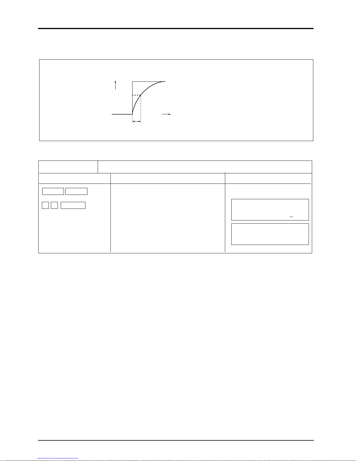
5.4 (21) Test mode
Description
The test mode is used to check for integrated conditions and action of the flow switch, etc. by
entering measuring flow rate simulately.
With base scale set to 0% and full scale to 100%, an arrival time from previous value to target
value can be set as shown below:
Data setting range: 0 to ±120%
Tracking time setting range: 0 to 900sec
Output
Output data
Base scale
time
Tracking time
Note: During measurement, set the test mode to “NOT USED”.
Operation (example) To set the tracking time to 15 seconds so that the target value reach from 0 to
100%.
Key operation
FUNC SYSTEM
or
or , ENTER
0 , ENTER
2 , 5 , ENTER
1 , 0 , 0 , ENTER
ESC ESC
Description
Select “Test mode”.
Select “Setting”.
Enter “0” with ten keys.
Enter “15” with ten keys.
Enter “100” with ten keys.
Press the key twice.
Display
TEST MODE
NOT USED
TEST MODE
SETTING
OUTPUT DATA
0%
TRACKING TIME
15 sec
OUTPUT DATA
100%
(Measurement display)
34
Page 41

6. MAINTENANCE AND INSPECTION
6.1 Maintenance
(1) LCD display unit
Expected service life of LCD is 7 years. It is recommended that LCD should be replaced with new
one in about 5 years since it is put into operation, or it may offer deteriorated contrast.
[Replacement procedure]
1) Power OFF
2) Remove the connector from the key panel and replace the LCD display unit (see parts list).
3) Assembly
4) Power ON
5) Check for normal operation
6.2 Inspection
(1) Daily check
Confirm the converter is operating normally by using the LCD display unit in accordance with
Item “7.1 How to confirm normal operation”.
35
Page 42

7. TROUBLESHOOTING
7.1 How to confirm normal operation
7.1 (1) When checking by LCD indicator
Indication
symbol
– XX. XXX m/s R
– XXXX. XXXX /s
Press ESC key if this indication
doesn't appear
C, H, W,
O, I
indication
7.1 (2) LCD indication when power turned ON
In case of no indication
System abnormal (CPU stopped)
Contact Fuji Electric.
Operation status
R Normal
E Range over
• Ultrasonic wave not
Ab-
transmitted normally
normal
inside pipe.
B
No
—
Backup error
Forward flow of fluid
Reverse flow of fluid
36
Page 43

7.1 (3) Detail check for abnormal status
Description
Status display at the upper right of the measurement screen is detailed as follows:
(Status display) (Contents of display) (Detailed Contents)
R : NORMAL
C : CAL. ERROR • Check for piping input data.
• Turn ON/OFF the power.
H : RECEIVED SIGNAL ERROR • Check for air bubbles in pipe
• Check for particles in pipe
W : WINDOW ERROR • Check for piping input data.
O : RECEIVED SIGNAL OVERFLOW • Check for the sensor mount-
ing method.
I : NO RECEIVED SIGNAL • Check for piping input data.
• Check for sensor installation.
• Check for cable connections.
• Check for type of sensor.
E : RANGE OVER • Check for output setting.
• Check for integral constant.
B : BACKUP ERROR • Non-volatile memory fault.
Operation (example) I appears at the upper right of the measurement screen.
Key operation
FUNC CHECK
ENTER
(Contens of display)
(Detailed contents)
(Detailed contents)
(Detailed contents)
Description
I : NO RECEIVED SIGNAL
CHECK
INPUT PIPE DATA
CHECK
SENSOR MOUNT
CHECK
CABLE CONNECT
CHECK
SENSOR TYPE
(Detailed contents)
ESC ESC
Press the key twice.
Display
(Measurement display)
37
Page 44

7.2 Faults and remedies
7.2 (1) LCD display abnormal
Status
No indication
appears.
Dark indication on
upper side.
Cause
• Power is not turned ON.
• Power voltage is low.
• Fuse is burnout.
• LCD is abnormal. Take remedy in “7.2 (5) Remedy for
hardware fault”
• DC power supply polarity is connected reversely.
• Power voltage is low.
• LCD is abnormal. Take remedy in “7.2 (5) Remedy for
hardware fault”
• DC power supply polarity is connected reversely.
• Hardware fault. Take remedy in “7.2 (5) Remedy for
hardware fault”
Random indication
Unclear display
Whole is dark
7.2 (2) Key abnormal
Status
No response at press
of input key
Specific keys can not
be operated.
Key operation is
• Ambient temperature low. (less than-10°C)
Increase the temperature.
• LCD indicator is worn out. Replace the LCD.
• Ambient temperature is high. (60°C or more)
Decrease the temperature.
Cause
• Hardware fault. Take remedy in “7.2 (5) Remedy for
hardware fault”
different from that
defined.
38
Page 45

7.2 (3) Measured value abnormal
Status
Minus (
-
) symbol
indicated on measured value
Measured value
fluctuates though
flow rate is constant.
Measured value is not
changed with change
in flow rate.
Cause
Remedy
• Connection between transmitter
and sensor is reversed. Connect correctly.
(Upstream and down stream
detectors should be connected
reversely)
• Flow of fluid is reversed.
• Straight pipe length is inadequate.
Move instrument to a place
where 10D can be maintained on upstream and 5D
on downstream.
• Pump, valve etc. which disturbs Attach instrument at
flow is located nearby. least 30D away
• There is pulsation in the Set the damping to increase
flow the response time.
Ultrasonic wave is not transmitted
inside pipe but measured value
remains unchanged (HOLD).
1. Installation is improper
• Error in piping specifica-
tions
• Sensor attached to welded
part
• Error in sensor mounting
dimensions
• Error in silicon appliance at
the time of mounting the
sensor
• Error in connection of the
sensor cable.
2.Problem with piping, fluid
Pipe not filled with fluid
Bubbles included in the fluid
If measured value becomes
normal when flow has
stopped, it indicates that
bubbles are contained in the
fluid.
When the sensor is mounted
right after the valve, cavitation may occur in the pipe,
resulting in entry of air
bubbles.
(Contined)
After confirming the cause,
remove the sensor and
apply sufficient amount of
silicone to the sensor.
Then, mount the sensor
again at a position slightly
away from previous position.
Fluid out a pipe filled with
fluid on the same pipeline,
and relocate the sensor to
the pipe.
• Attach the sensor to the
lowest place on the pipeline.
Eliminate the bubbles.
• Raise the level of the pump
well.
• Check the shaft seal of the
pump.
• Retighten the flange of
negative pressure pipe.
• Arrange so that fluid doesn’t
fall into the pump well
Move the sensor to a place
where no bubbles are
contained.
• Pump inlet side
• Upstream side of valve
39
Page 46

Status
Cause
Remedy
(Continued)
Turbidity is high.
Turbidity is higher than inflow
water contamination or return
sludge.
Scale deposits on the inside of
old pipe
Thick lining
Mortar lininig is several ten
millimeters thick
Separation of lining
This is gap between lining and
pipe.
Sensor is mounted on bent or
tapered pipe.
3. Effect of external noise
•There is a radio broadcast
station nearby.
•Measurement conducted near a
passage of vehicles or electric
cars.
• Change sensor
mounting from V
method to Z method.
• Move sensor to a
place of smaller
diameter on the
same pipeline.
• Relocate sensor to
another place or pipe
line.
Mount sensor on a
straight pipe.
• Keep the cable
between converter
and sensor as short
as possible.
• Ground the converter and piping.
Measured value not
zero when fluid stops
flowing.
• Mounting of sensor incorrect
• Mounting dimensions
• Sensor is separated from pipe
4. Hardware fault
• Fluid forms a convection inside
the pipe.
• Zero point adjustment
• Pipe is not full of water or it is
empty of water when water
stops flowing.
• Mount sensor parallel with pipe at the
correct position.
• Press sensor so it is
securely mounted on
the pipe.
Refer to Item “7.2(5)
Remedy for hardware
fault”.
This is normal.
• Readjust the zero
point after fluid has
stopped flowing.
This is normal.
• The value may vary
at Item “5.4(4) Setting
of output at abnormal
measurement”.
40
Page 47

Status
Cause
Remedy
Error in measured
value
• Input piping specifications
differ from the actual ones.
• Scale deposits on old pipe
• Length of straight pipe is inadequate. (should be at least 10D
upstream and 5D downstream.)
Error of about 3%
occurs when inner
diameter differs by
1%.
• Input the correct
specifications
• Input scale as a
lining.
Change the sensor to
another mounting
position (upstream of
disturbing objects)
No disturbing objects
in flow within 30D
upstream without
pump, valve, combined pipe, etc.
• Try mounting the
sensor at various
angles versus the
pipe section, and
mount it where
average value is
obtained.
• Pipe is not filled with fluid or
sludge is deposited in the pipe.
Occurs particularly
where sectional area
is small.
• Move sensor
to a vertical pipe.
41
Page 48

7.2 (4) Analog output abnormal
Status
Current output is not
matched though
indication value is not
0.
Output is 0mA.
Output is below 4mA
when indication is 0.
Output is greater than
20mA.
Indication is changed
but analog output
remains the same.
Indication does not
agree with analog
output.
Analog output
doesn’t change even
after it has been
adjusted.
Cause
Range setting is not
performed.
Cable is disconnected.
Zero adjustment of analog
output has deviated.
E is displayed on LCD
indicator. Note)
Span adjustment is incorrect.
Output load is greater than
1kW.
Zero or span of analog output
has deviated.
Hardware falut
Remedy
• Set.
Adjust the analog output.
Range over:
• Reset analog output range
data.
• Adjust the analog output.
• Reduce the load to 1kW
or less.
Adjust the analog output.
Contact Fuji Electric.
Note: When the base scale is not set to 0 within the range of an analog output, the flow
display may not be matched with the analog output.
7.2 (5) Remedy for hardware fault
When hardware is in trouble after following “6. Maintenance and inspection” and “7.
Troubleshooting”, details of trouble and self-check should be notified to Fuji Electric.
42
Page 49

8. MOUNTING METHOD
8.1 Mounting of sensor
8.1 (1) Mounting procedure of sensor
Mount the sensor on the pipe, and perform the following works in order before making
measurement.
8.1 (2)
8.1 (3) Selection of mounting method
8.1 (4)
8.1 (5)
8.1 (6)
8.1 (7) Connection of cable
8.1 (8) Mounting of small type
Selection of mounting place
Processor of sensor
mounting surface
Determination of
mounting position
Cable end termination
to small type sensor and
sensor with small
diameter
sensor and pipe with
small diameter on pipe
8.1 (10) Connection of signal
cable to large type
sensor
8.1 (11) Mounting of large type
sensor on pipe
8.1 (12) Mounting of high
temperature sensor
on pipe
8.1 (9) Assembly procedure
of sensor
43
Page 50

8.1 (2) Selection of mounting place
Mounting place for the sensor, i. e. conditions of piping where flow rate is measured, has considerable influence on measurement accuracy.
A place satisfying the following conditions should be selected.
1) A place where there is a straight pipe portion of 10D or more on upstream side and of 5D or
more on the downstream side.
2) A place where there are no factors which disturb the flow (pumps, valves, etc.) within 30D on
upstream side.
3) Pipe must be filled up with fluid. No bubbles should be contained.
4) Make sure that a maintenance space is provided around the piping where the sensor is
mounted. (See Fig. 8-1.)
Note) A space should be provided so that maintenance work can be made with workers
standing on both sides of the piping.
8" or
more
more
200 or
Note
Note
8" or
more
more
200 or
D + 48" or more
24" or
more
D
24" or
more
D : Pipe diameter
Fig.8-1 Space required for mounting sensor
CAUTION
1. Where a horizontal pipe is used, install the sensor within ±45° from the horizontal plane.
Where a vertical pipe is used, the sensor can be installed anywhere.
Pipe
45°
Horizontal
45°
2. Avoid installing the sensor on a deformed portion of pipe or welded portion of pipe, or on
flange.
2,000 or more
80" or more
Welded portion Flange or weld Welded portion
44
Page 51

8.1 (3) Selection of mounting method
There are two ways for mounting the sensor, the V method and the Z method (See Fig. 8-2).
Approx. D
Sensor
D
V method
D
Approx. D/2
Sensor
Z method
Fig. 8-2 Mounting method
The Z method should be used in the following cases.
• Where a mounting space is not available. (As shown in the figure above, the mounting dimension with the Z method is about half of that with the V method).
• When measuring fluid of high turbidity such as sewage.
• When the pipe has a mortar lining.
• When the pipe is old and has a thick accumulation of scale on its inner wall.
Selection standard
For a large size sensor with inside diameter of more than 12 in., the Z method is recommended for mounting.
Sensor
Small type
sensor
Type : FLW12
Large type
sensor
Type : FLW51
High temperature
sensor
FLW32
Z
method
V
method
Z
method
V
method
: Range noted in specifications
: Range specified with piping material
(FRP, PVC or other plastic materials)
8.1 (4) Processing of sensor mounting surface
Using thinner and/or sandpaper, remove pitch, rust and unevenness over a width of (L) + 8 in. on
the pipe circumference where the sensor is mounted.
Note) If there is a jute winding on the pipe circumference, remove it and carry out the above
processing.
Jute winding
1" 2" 4" 8" 12" 16" 40" 120" 240"
Inside diameter (inches)
Pipe
L + 8"
45
Page 52

8.1 (5) Determination of mounting position (with Z method for large and small types)
Edge should be even.
Straight line A
Carry out the following to determine the mounting position.
Gauge paper is necessary for this work. (Refer to Appendix 1. “How to make gauge paper”.)
1. Align the edge of gauge paper with a point about 4 in. from
one end of the processed section, and wrap the paper around
the pipe so that the line drawn on the paper is parallel with the
pipe shaft. (The paper should be taped to prevent slipping.)
At this time, make sure that the paper edge is even.
2. Extended the line drawn on the paper and mark a straight line A
on the pipe.
3. Mark a line along on edge of the paper. Assume the intersection
of the line and the straight line A is A
.
0
4 in.
A
0
V method
Example) L = 8 in.
8 in.
A
0
A
2
4. Remove the gauge paper and measure
the mounting dimension from A
.
0
Then , draw a line which crosses the
straight line A (determine the position
A
).
2
A0 and A2 are the mounting position.
Z method
B
0
A
0
Straight line B
B0,B
1
A0,A
A
1
B
1
4. Measure the circumference of the pipe from the
point A
between the point B
, and mark a line (straight line B)
0
and B1 obtained at 1/2 of
0
the circumference.
Example) L = 4 in.
4 in.
B2B
0
A
0
B
B
0
2
5. Put a mark at point B0 and remove the gauge
paper.
Measure the mounting dimension from B
and
0
mark a line crossing the straight line B
(determine the position B
).
2
In this way, the mounting position is determined.
and B2 are the mounting position.
A
0
1
46
Page 53

8.1 (6) Cable end treatment
The end of coaxial cable is treated at the factory prior to delivery. If the cable needs to be cut
before use, the conductor and the shielding wires should be treated using clamp terminals.
Outer shielding wire (green)
Note) When cutting the coaxial cable, make sure that the upstream side and the downstream side
are the same in length.
Shielding wire (black, G)Conductor (white, +)
Clamp terminal
47
Page 54

8.1 (7) Connection of cable to small type sensor
Cable clamp
G
+
1. Loosen the earth screw and the retaining knob on
the sensor using a screwdriver, then remove the
cover from the sensor.
Cover
Loosen
Retaining knob
2. Select a mounting position on the pipe.
Note) Mount the sensors so that the upstream and
downstream sensors can be distinguished with
each other.
Remove the cable clamp and insert the coaxial
cable through the cable lead-in port.
4. Secure the coaxial cable with the cable clamp.
5. Remove foreign matters from the terminals, and
mold the while terminal block with silicone filler.
• Cut off the tip of the silicone filler tube.
Apply silicone to the terminal block while
pressing the head of the tube against the bottom of
terminals.
At this time, care should be taken to prevent entry
of air bubbles.
3. Connect the cable to the terminal (G, +) and the
earth screw.
Note) After connecting the outer shielding wire to
the earth screw, be sure to bend the amplifier
terminal.
Outer shielding
terminal
Outer shielding wire
Silicone filler
Bend
Earth screw
Terminal
6. Put the cover on the sensor.
Coaxial cable
48
Page 55

8.1 (8) Mounting of small type sensor on pipe
The small type sensor is mounted on pipe with a diameter of ø50 to 250 (V method) or ø150 to
400 (Z method) for measurements.
1. Mounting of sensor (V method)
Mounting the sensor using the following procedure.
For mounting, prepare a scale or a slide calipers.
1. Loosen the retaining knob A (4 places), slide the
sensor so as to match the mounting dimension,
place a scale on the mounting dimension reference
surface C and adjust the dimension, then tighten
the retaining knob A.
Mounting dimension
reference surface C
Retaining
knob A
Mounting
dimension
Scale
2. Spread silicone filler over the whole transmitting
side of the sensor. Care should be taken to
prevent entry of air bubbles.
3. Raise the end of the pipe fitted with the sensor,
and attach the yellow ring on the chain to the
hook.
Pipe end Wire
Yellow
Red
Spring
Ring
Attach the other chain to the other hook of sensor,
and secure it loosely.
4. Pull the red ring and attach it to the hook.
Use the same procedure for the other sensor.
Clean the surface of the pipe and mount the
sensor.
Turn over the frame end so that the sensor makes
a close contact with the pipe.
Transmitting
side
Press the sensor firmly against the pipe.
Ensure that the sensor makes a close contact with
the pipe.
49
Page 56

2. Mounting of sensor (Z method)
Mounting the sensor using the following procedure
1. Spread silicone filler over the whole transmitting
side of the sensor. Care should be taken to
prevent entry of air bubbles.
Slincone filler
Clean the surface of the pipe, then mount the
sensor.
2. Press the sensor against the pipe. Align the center
of the sensor with the intersection of the marking
line, and the mounting dimension reference
surface with the marking line.
3. Make sure that the center mark on the sensor is
aligned with the marking line. Then, connect the
coaxial cable to the transmitter.
To be aligned
Marking line
Center mark
Note) Do not pull the coaxial cable. If it is pulled,
the sensor is shifted which results in incorrect
measurements due to poor contact with the
pipe.
50
Page 57

8.1 (9) Assembling procedure of the sensor
When the small type sensor (FLW1) is shipped with cables of more than 32.8 ft. in length, it is
delivered, disassembled since cable weight is applied to the stand or piping of the sensor during
shipment.
Follow the procedure given below.
Assemble of parts
1. Be sure to read the “Cautions” before assembling
the parts.
Insert the frame end onto one side of 2 pipes.
Apply a coat of silicone to
the frame end. Take care of
the direction of the frame
end and the slit of pipe.
Slit
Insert
Silicone
filler
Pipe
Insert
Slit
Insert
Boss
Frame end
After inserting the pipes, tap the frame end with a
plastic hammer or the like.
2. Loosen the tightening knob on the sensor and
insert the pipes.
3. Insert another sensor onto the pipes.
Insert it in the correct direction.
4. Insert the frame end onto the other side of pipes.
Assembling method is the same as 1.
Tightening knob
The sensor should be inserted in the correct
direction.
Note) After assembling the sensor, leave it at room temperature for a day to harden the filler (to
obtain the required assembling strength).
Insert
51
Page 58

8.1 (10) Connection of cable to large type sensor
1. Slightly move the sensor cover and remove it
using an screwdriver or the like.
Cover
Transmitting
direction mark
3. Confirm the mounting position on the pipe.
• Align the transmitting direction marks so that
they are facing with each other.
Transmitting
direction mark
3. Connect the coaxial cable to the terminals (G, +)
and secure the cable with the cable clamp.
Cable retain
4. Remove foreign objects from the terminal section,
and mold the whole terminal section with silicone
filler.
• Cut the tip of the silicone filler tube. Apply
silicone while pressing the head of the tube
against the bottom of the terminal section
Be careful not to let babbles form.
52
Silicone filler
Cable clamp
Coaxial cable
Silicone filler
Coaxial cable
Page 59

8.1 (11) Mounting of large type sensor on pipe
1. Adjustment of guide plate height
Attach the sensor to the pipe. Make sure that it is
parallel with the pipe shaft.
Retaining screw
Guide plate
Transmitting
side
Transmitting
direction mark
Loosen the guide plate retaining screw, and slide
the plate until its edge and the transmitting side
are in contact with the pipe surface.
Tighten the retaining screw.
2. Setting of wire rope length
Place the sensor on the marking line and attach
the wire rope and mounting spring.
3. Mounting of sensor
• Clean the sensor transmitting surface and pipe
mounting surface.
• Spread silicone filler over the whole transmitting surface of the sensor.
• The thickness of silicone filler should be
about 3mm.
Transmitting side
Pipe
• Spread the wire rope near the marking line to
right and left. Attach the sensor firmly to the
pipe and hook the wire rope.
Mounting
spring
600
180
Marking line
Sensor
Loosen wire clip
and pull wire
rope
Pipe
Loosen the wire clip, stretch the wire rope until
the overall length of the mounting spring becomes
180mm, and secure the wire clip (free length of
the mounting spring is 110mm).
Remove the sensor with the wire rope fixed in
place.
• Make sure that the matching mark on the
sensor is aligned with the marking line. Also,
make sure the transmitting direction marks on
the sensor are facing with each other.
Mounting spring
Marking line
Sensor
Pipe
Transmitting
direction
mark
Marking line
Matching mark
• Confirm that the sensor matching mark is
aligned with the marking line, then connect the
coaxial cable to sensor.
Note) Do not pull the coaxial cable. If it is pulled,
the sensor may move from its mounting
position which affects correct measurements.
53
Page 60

8.1 (12) Mounting of high temperature sensor on pipe
1. By loosening lock nuts, slide the sensor to fit the
mounting size displayed on the converter.
Tighten the lock nuts.
Locking nut
BN connector
Element
holder
Saddle
Mounting
Cursor
Frame
Scale
dimension (L)
2. Spread high-temperature grease over the whole
transmitting surface of the sensor.
High -temperature
grease
3. Mount the sensor saddles on the pipe with stainless belt.
Stainless belt
4. Check that the sensor is properly attached in
parallel to the pipe and it is mounted according to
the mounting dimension. Then, turn the element
holder clockwise, so that the sensor makes a close
contact with the pipe.
Transmitting surface
Element holder
Turn the element holder counterclockwise to
return the sensor. Clean the surface of the pipe
and mount the sensor on the pipe.
Element holder
Cable
Stop turning the element holder where the transmitting surface contact the surface of pipe, and
thus the element holder won’t rotate. Don’t turn
it excessively.
54
Page 61

APPENDIX 1. SPECIFICATIONS
(1) Specifications
Services
• Measuring fluid : Homogeneous liquid suitable for the pass of ultrasonic wave (water, sea
water or oil Even liquid of which sound velocity is not clear is measurable)
• Turbidity of fluid : 10,000 deg. (mg/l) or less
• Flow : Uniform flow, free from drift in pipe filled with fluid.
-
• Fluid temperature : Small type sensor ;
Large type sensor ;
High temperature sensor ;
-
• Measuring range :
Piping conditions
• Material of piping : Carbon steel, stainless steel, cast iron, FRP, asbestos, copper, aluminum,
• Diameter of pipe : Small type sensor ø2 to ø16 in.
• Lining material : None, tar epoxy, mortar, rubber, or material with known sound velocity
• Length of straight pipe: Upstream side : 10D or more
Accuracy rating
105 to 0 to +105 ft./s
acrylic, etc.
Large type sensor ø8 to ø236 in.
High temperature sensor ø2 to ø16 in.
Downstrem side : 5D or more (D:inner diameter of pipe)
Diameter
40 to +176°F
-
40 to +176°F
-
40 to +392°F
Flow velocity Accuracy
ø2 to ø12 in. or less
ø12 to ø236 in.
Converter (Type : FLV)
• Measuring method : Propagation delay time system
• Power supply : 100 to 240V ±10% AC, 50/60Hz
• Electric power : Approx. 20VA (about 10W)
LCD
•
• Operation unit : Seat key (20 keys)
• Reset after power interruption : Backup by non-volatile memory (available for 10 years)
• Response speed : 0.5 sec or less
• Output signal : Analog signal 4 to 20mA DC, 1point (load resistance:0 to1kW)
• Ambient temperature : +14 to +140°F
• Ambient humidity : 90%RH or less
• Enclosure : Immersion-proof (aluminum casting case), IP65 or equivalent
• Color of paint : Cover (blue), case (silver)
• Dimensions : H10.91 ´ W9.61 ´ D3.74 ft.
• Mass : Approx. 10 lbs.
: Character display (16th digits, 2 lines) with back light
Contact signal open collector (30V DC, 0.1A), 1 point
6.56 to 105 ft./s 1.0% of rate
0 to 6.56 ft./s 3.3 ft./s
3.26 to 105 ft./s 1.0% of rate
0 to 3.26 ft./s 0.03 ft./s
A-1
Page 62

Sensor (Type : FLW)
• Mounting method : Pipe-mounting
• Mounting method of sensor: V method or Z method
• Attaching belt/wire : Small type sensor: stainless chain
Large type sensor: stainless wire
High temperature sensor: stainless belt
• Sound coupler : Silicon rubber
• Signal cable : Dedicated coaxial cable (standard 16 ft., max.492 ft.)
• Connection : Terminal screw
High temperature sensor: BNC connector
-
• Ambient temperature :
4 to +140°F
• Ambient humidity : 100%RH or less
• Enclosure : Immersion-proof type (IP67 or equivalent)
High temperature sensor: Drip-proof type (IP52 or equivalent)
• Material :
• Dimensions and mass :
Types Sensor case Guide rail
Small type sensor Plastic SUS304 + plastic
Large type sensor Plastic ——————
High temperature sensor SUS304 Aluminum alloy + SUS304
Types Dimensions (H ´ W ´ D) Mass
Small type sensor 1.67 ´ 2.62 ´ 1.31 ft. Approx. 2.2 lbs.
Large type sensor .34 ´ .3 ´ .2 ft. Approx. 3.1 lbs.
High temperature sensor 1.74 ´ .17 ´ .67 ft. Approx. 3.6 lbs.
A-2
Page 63

(2) Function
• Display language : Japanese (Katakana)/English selectable
• Instantaneous value display function :Flow velocity/flow rate (with flow direction) selection
Unit : metric system/inch system selectable
Metric system English sytem
Flow velocity m/s ft/s
Flow rate l/s, l/m, l/h, Ml/d gal/s, gal/m, gal/h, Mgal/d
3
/s, m3/m, m3/h, Mm3/d ft3/s, ft3/m, ft3/h, Mft3/d
m
BBL/s, BBL/m, BBL/h, MBBL/d BBL/s, BBL/m, BBL/h, MBBL/d
• Integral value display function : forward integral value selection
Unit : metric/inch selectable
Metric system English sytem
Integral value ml, l, m
3
, km3, Mm
3
gal, kgal, ft3, kft3, Mft
mBBL, BBL, kBBL mBBL, BBL, kBBL
• Instantaneous value output function : analog signal 4 to 20mA DC
• Damping : 0 to 100 sec (time constant)
• Low flow cut : 0 to 16.4 ft./s
• Output setting function : Scaling/limit of current output, burnout setting
Current output calibration available
• Communication function : nstantaneous flow velocity, instantaneous flow rate, integral value,
status
• Auto range selection : Judgement of range by 2 range and contact output
• Forward/reverse selection : Judgement of flow direction by forward/reverse range and contact
output
• Integrated pulse output: 5P/s, max. pulse width (50, 100ms selectable)
• Others : Self diagnosis function
3
(3) Principle of measurement
With ultrasonic pulses propagated diagonally from the upstream and downstream sides, flow rate is
measured by detecting the time difference obtained by the flow of fluid.
Flow velocity V
Sensor on downstream side
Sensor
Sensor on upstream side
t
1t2
A-3
Conver-
D
ter
Output signal
Page 64

(4) Mounting of sensor
Ultrasonic oscillator Pipe
(5) Construction
(1) Single-measuring-path system (V method)
Cable
Sensor
Plastic wedge
Lining
DC
4 to 20mA
(2) Single-measuring-path system (Z method)
Cable
Sensor
Contact
Converter
DC
4 to 20mA
Contact
Converter
A-4
Page 65

APPENDIX 2. HOW TO MAKE GAUGE PAPER
1. Prepare a rectangular sheet of paper (or vinyl sheet) with its length of more than 4D and width of
8 in. (D, if possible).
D : Pipe diameter
®
®
®
8 in. (or D) or
®
4D or more
®
®
Parallel
2. Draw a line perpendicular to the long side at a point about 4 in. from one end.
Approx. 4 in.
®
®
more
Line
B-1
Page 66

APPENDIX 3. COMPOSITION OF KEY OPERATION
(1) SETTING OF MEASURE DISPLAY
FUNC DISP
1 : DISPLAY KIND
2 : FLOW UNIT
VELOCITY
RANGE %
TOTAL FORWARD
TOTAL REVERSE
TOTAL DIFF.
F : TOTAL PULSE
R : TOTAL PULSE
l/s
l/m
l/h
Ml/d
m3/s
m3/m
m3/h
Mm3/d
BBL/s
BBL/m
BBL/h
MBBL/d
(METRIC) (ENGLISH)
gal/s
gal/m
gal/h
Mgal/d
ft3/s
ft3/m
ft3/h
Mft3/d
BBL/s
BBL/m
BBL/h
MBBL/d
[Initial value]
[Velocity]
[m3/s]
[ft3/s]
3 : DECIMAL POINT
00000000. [00000.000]
0000000.0
000000.00
00000.000
0000.0000
000.00000
00.000000
0.0000000
C-1
Page 67

(2) SETTING OF PIPING SPECIFICATIONS
FUNC PIPE
SENSOR SPACING
OUTER DIAMETER
(13 to 6100 mm) [Entry of dimension of outer circumstance]
(0.52 to 240 inch)
PIPE MATERIAL
CARBON STEEL
STAINLESS STEEL
PVC
COPPER
CAST IRON
ALUMINUM
FRP
ASBESTOS
OTHERS
DUCTILE IRON
PEEK
PVDF
ACRYLIC
OTHERS
PIPE S.V. (1000 to 3700 m/s)
(3281 to 12140 ft/s)
WALL THICKNESS
(0.1 to 100 mm)
(0.01 to 4 inch)
LINING MATERIAL
NO LINING
TAR EPOXY
MORTAR
RUBBER
TEFLON
PYREX GLASS
PVC
OTHERS
LINING S.V. (1000 to 3700 m/s)
(3281 to 12140 ft/s)
LINING THICKNESS (0.01 to 100 mm)
(0.01 to 4 inch)
KIND OF FLUID
WATER
SEAWATER
OTHERS
FLUID S.V. (500 to 2500 m/s)
(1641 to 8208 ft/s)
VISCOSITY (0.001E-6 to 999.999E-6 m2/s)
-
6 to 999.9E-6 ft2/s)
(0.1E
SENSOR MOUNTING
V METHOD
Z METHOD
SENSOR TYPE
FLW11
FLW12
FLW22
FLW32
FLW50
FLW51
TRANS. VOLTAGE
1TIME
2TIME
4TIME
8TIME
Press "/p" key. Converted into
outer diameter
Note) Displayed when selecting "OTHERS"
from the pipe materials.
Note) Displayed when selecting "OTHERS"
from the lining materials.
Note) Displayed when selecting "OTHERS"
from the lining materials.
Note) Displayed when selecting "OTHERS"
from the lining materials.
[13 mm]
[0.52 inch]
[Carbon steel]
[1000 m/s]
[3281 ft/s]
[0.1 mm]
[0.01 inch]
[NO LINING]
[1000 m/s]
[3281 ft/s]
[0.01 mm]
[0.01 inch]
[WATER]
[500 m/s]
[1641 ft/s]
-
[1.003E
6 m2/s]
[10.7E
-
[V METHOD]
[FLW12]
[4 TIME]
6 ft2/s]
C-2
Page 68

(3) SETTING OF FLOW SWITCH
FUNC FLOW SW
FLOW SW LOW
FLOW SW HIGH
FLOW SW HYS.
(0 to ±32 m/s)
(0 to ±105 ft/s)
(0 to ±32 m/s)
(0 to ±105 ft/s)
(0 to 20%)
(4) SETTING OF OUTPUT
(METRIC) (ENGLISH)
RANGE UNIT
RANGE TYPE
OUTPUT LIMIT LOW (–20 to 120 %)
OUTPUT LIMIT HIGH (–20 to 120 %)
SINGLE RANGE
AUTO 2 RANGES
BI-DIR. RANGE
m/s
l/s
l/m
l/h
Ml/d
m3/s
m3/m
m3/h
Mm3/d
BBL/s
BBL/m
BBL/h
MBBL/d
BASE SCALE
FULL SCALE
BASE SCALE
FULL SCALE1
FULL SCALE 2
RANGE HYSTERESIS
Same as AUTO 2 RANGES
ft/s
gal/s
gal/m
gal/h
Mgal/d
ft3/s
ft3/m
ft3/h
Mft3/d
BBL/s
BBL/m
BBL/h
MBBL/d
(0 to ±32 m/s)
(0 to ±105 ft/s)
(±0.3 to ±32 m/s)
(±1 to ±105 ft/s)
(0 to ±32 m/s)
(0 to ±105 ft/s)
(±0.3 to ±32 m/s)
(±1 to ±105 ft/s)
(±0.3 to ±32 m/s)
(±1 to ±105 ft/s)
(0 to 20%)
[0 m/s]
[0 ft/s]
[32 m/s]
[105 ft/s]
[10 %]
[m/s]
[ft/s]
[SINGLE RANGE]
[0 m/s]
[0 ft/s]
[32 m/s]
[105 ft/s]
[0 m/s]
[0 ft/s]
[32 m/s]
[105 ft/s]
[32 m/s]
[105 ft/s]
[10 %]
[–20 %]
[120 %]
OUTPUT BURNOUT
BURNOUT TIMER (0 to 900 sec)
(5) SETTING OF DAMPING
FUNC DAMP
DAMPING (0 to 100 sec)
NOT USED
HOLD
UPPER
LOWER
ZERO
[NOT USED]
[0 sec]
[5 sec]
C-3
Page 69

(6) SETTING OF LOW FLOW OUTPUT CUT
FUNC CUT OFF
CUT OFF
(0 to 5 m/s)
(0 to 16.4 ft/s)
(7) SETTING OF TOTAL OUTPUT
FUNC TOTAL
TOTAL MODE
TOTAL UNIT
TOTAL RATE
F : TOTAL PRESET
F : TOTAL SW
R : TOTAL PRESET
R : TOTAL SW
TOTAL STOP
TOTAL RUN
TOTAL RESET
ml
l
m3
km3
Mm3
mBBL
BBL
kBBL
(METRIC)
(0 to 9999999)
(0 to 9999999)
(0 to 9999999)
(0 to 9999999)
(0 to 9999999)
gal
kgal
ft3
kft3
Mft3
mBBL
BBL
kBBL
(ENGLISH)
[0 m/s]
[0 ft/s]
[TOTAL STOP]
[m3]
[ft3]
[0]
[0]
[0]
[0]
PULSE WIDTH
50 msec
100 msec
(8) ZERO ADJUSTMENT
FUNC ZERO
ZERO MODE
SET ZERO
CLEAR
(9) CALIBRATION OF MEASUREMENT VALUE
FUNC CAL (2)
CALIBRATON ZERO
CALIBRATION SPAN
(0 to ±5 m/s)
(0 to ±16.4 ft/s)
(0 to 200%)
[50 msec]
[SET ZERO]
[0 m/s]
[0 ft/s]
[100 %]
C-4
Page 70

(10) SETTING OF SYSTEM CONDITION
FUNC SYSTEM
SYSTEM OF UNIT
LANGUAGE
OUTPUT CHECK (-20 to 120 %)
OUTPUT ADJUST
STATUS CHECK
TEST MODE
METRIC [METRIC]
ENGLISH
ENGLISH
JAPANESE
SKIP
SETTING 4 mA
20 mA
CHANNEL 1
CHANNEL 2
NOT USED
SETTING INPUT DATA (0 to ±120 %)
OFF
ON
OFF
ON
TRACKING TIME (0 to 900 sec)
[ENGLISH]
[0 %]
[4mA]
[OFF]
[OFF]
[NOT USED]
[0 %]
[0 sec]
C-5
Page 71

(11) SELECTING OF STATUS
FUNC STATUS
STATUS CHANNEL
CHANNEL 1
STATUS SEL.:CH1
STATUS MODE:CH1
CHANNEL 2
same as CHANNEL 1
NOT USED
SIGNAL ERROR
F : TOTAL PULSE
R : TOTAL PULSE
FLOW SW HIGH
FLOW SW LOW
F : TOTAL ALARM
R : TOTAL ALARM
F : TOTAL OVERFLOW
R : TOTAL OVERFLOW
FULL SCALE2
R : FLOW DIRECTION
RANGE OVER
BACKUP ERROR
NORMAL
REVERSE
[NOT USED]
[NORMAL]
STATUS INF. (only display) Note) STATUS OFF®0
STATUS ON®1
SIGNAL ERROR
F : TOTAL PULSE
R : TOTAL PULSE
FLOW SW HIGH
FLOW SW LOW
F : TOTAL ALARM
R : TOTAL ALARM
F : TOTAL OVERFLOW
R : TOTAL OVERFLOW
FULL SCALE2
FLOW DIRECTION
RANGE OVER
reserve
reserve
reserve
BACKUP ERROR
C-6
Page 72

(12) ERROR CHECK
FUNC CHECK
R : NORMAL
C : CAL. ERROR CHECK PIPE DATA
POWER OFF®ON
H : RECEIVED
SIGNAL ERROR
W : WINDOW ERROR CHECK PIPE DATA
O : RECEIVED
SIGNAL OVERFLOW
I : NO RECEIVED
SIGNAL
E : RANGE OVER CHECK OUTPUT RANGE
B : BACKUP ERROR EEPROM FAULT
S : WINDOW SCANNING PLEASE WAIT NOW
T : TEST MODE TEST MODE RUNNING
CHECK BUBBLES IN PIPE
CHECK PARTICLES IN PIPE
CHANGE MOUNTING METHOD
CHECK PIPE DATA
CHECK SENSOR MOUNT
CHECK CABLE CONNECT
CHECK SENSOR TYPE
CHECK TOTAL RATE
C-7
Page 73

APPENDIX 4. PIPING DATA
Stainless steel pipe for pipe arrangement (JIS G3459-1988)
Nominal
diameter
(in.)
AB
.6 .9 .06 .08 .10 .11 .15 .22
.8 1.1 .06 .08 .10 .11 .15 .22
1.0 1.3 .06 .11 .12 .13 .18 .25
1.3 1.7 .06 .11 .12 .14 .19 .25
1.6 1.9 .06 .11 .12 .15 .20 .28
2.0 2.4 .06 .11 .14 .15 .22 .34
2.6 3.0 .08 .12 .14 .20 .28 .37
3.1 3.5 .08 .12 .16 .22 .30 .44
3.5 4.0 .08 .12 .16 .22 .32 .50
4.0 4.5 .08 .12 .16 .24 .34 .53
4.9 5.5 .11 .13 .20 .26 .37 .63
5.9 6.5 .11 .13 .20 .28 .43 .72
8.0 8.5 .11 .16 .26 .32 .50 .91
10.0 .39 10.5 .13 .16 .26 .37 .59 1.13
12.0 .47 12.5 .16 .18 .26 .41 .69 1.31
13.8 .55 14.0 — .44 .75 1.41
15.7 .63 16.0 — .50 .84 1.59
17.7 .70 18.0 — .56 .94 1.781.37
19.7 .79 20.0 — .59 1.03 1.97
21.7 .87 22.0 — .63 1.13 2.131.63
23.6 .94 24.0 — .69 1.34 2.341.81
25.6 1.02 26.0 —
.02
.03
.04
.05
.06
.08
.10
.12
.14
.16
.20
.24
.32
Outer
diameter
(in.)
Schedule
5S
Thickness
(in.)
Schedule
10S
Thickness
(in.)
—
—
—
—
—
—
—
Schedule
20S
Thickness
(in.)
—
—
—
—
—
—
—
Normal thickness
Schedule40Schedule80Schedule
Thickness
(in.)
.74 1.34 2.531.93
Thickness
(in.)
120
Thickness
(in.)
—
—
—
—
—
—
—
—
—
.44
.50
.56
.72
.84
1.00
1.09
1.22
1.50
Schedule
160
Thickness
(in.)
Polyethylene pipe for city water (JIS K6762-1982)
Nominal
diameter
Outer
diameter
(in.)
1.0 1.34 .20 3.06 .14 2.33
1.2 1.65 .22 4.24 .16 3.31
1.6 1.89 .26 5.70 .18 4.27
2.0 2.36 .31 8.75 .20 6.00
(in.)
.5 .85 .14 1.33 .10 1.03
.8 1.06 .16 1.95 .12 1.57
1st type (Soft pipe)
Thickness
(in.)
Weight
(lb./ft.)
2nd type (Hard pipe)
Thickness
(in.)
Weight
(lb./ft.)
Galvanized steel pipe for city water SGPW (JIS G3442-1988)
Nominal pipe
(A)
.6 .11
.8 .11
1.0 .13
1.3 .14
1.6 .14
2.0 .15
2.6
3.1
3.5
4.0
4.9
5.9
8.0
10.0
12.0
(B)
.02
.03
.04
.05
.06
.08
.10
.12
.14
.16
.20
.24
.32
.39
.47
Outer diameter
(in.)
.9
1.1
1.3
1.7
1.9
2.4
3.0
3.5
4.0
4.5
5.5
6.5
8.5
10.5
12.5
Thickness
(in.)
.17
.17
.17
.18
.18
.20
.23
.26
.27
D-1
Page 74

Asbestos cement pipe for city water (JIS A5301-1971)
Nominal
diameter
of connected
(in.)
2.0 .39 2.76
3.0 .39 3.74
4.0 .47 4.88 .39 4.72
4.9 .55 6.02 .43 5.79
5.9 .62 7.17 .47 6.85
8.0 .83 9.53 .59 9.06
10.0 .91 11.65 .75 11.34
12.0 1.02 13.86 .87 13.54
13.8 1.18 16.14 .98 15.75
15.7 1.38 18.50 1.14 18.03
17.7 1.54 20.79 1.26 20.24
19.7 1.69 23.07 1.38 22.44
23.6 2.05 27.72 1.65 26.93
27.6
31.5
35.4
39.4
43.3
47.2
51.2
59.1
Thickness
portion (in.)
—
—
—
—
—
—
—
—
1st type
Outer diameter
of connected
portion (in.)
—
—
—
—
—
—
—
—
2nd type
Thickness
of connected
portion (in.)
Outer diameter
of connected
——
——
1.93
2.20
—
—
—
—
—
—
portion (in.)
31.42
35.91
—
—
—
—
—
—
3rd type
Thickness
of connected
portion (in.)
—
—
.35 4.65
.37 5.67
.39 6.69
.51 8.90
.61 11.06
.71
.81
.91
1.02
1.12
1.34
1.54
1.73
1.93
2.13
2.32
2.56
2.87
3.19
Outer diameter
of connected
portion (in.)
—
—
13.23
15.39
17.56
19.76
21.93
26.30
30.63
34.96
39.29
43.62
47.95
52.36
58.90
65.43
4th type
Thickness
of connected
portion (in.)
—
—
—
—
—
.43
.47
.55
.62
.71
.79
.87
1.02
1.18
1.34
1.50
1.65
1.81
1.97
2.24
2.48
Outer diameter
of connected
portion (in.)
—
—
—
—
—
8.74
10.79
12.91
15.04
17.17
19.29
21.42
25.67
29.92
34.17
38.43
42.68
46.93
51.18
57.64
64.02
Polyethlene pipe for general use (JIS K6761-1979)
Nominal
diameter
(in.)
Outer
diameter
(in.)
1st type
Thickness
(in.)
.5 .85 .11 .09
.8 1.06 .12 .09
1.0 1.34 .12 .10
1.2 1.65 .14 .11
1.6 1.89 .14 .12
2.0 2.36 .16 .14
2.6 3.00 .20 .16
3.0 3.50 .22 .20
4.0 4.49 .24 .22
4.9 5.51 .26 .26
5.9 6.50 .28 .28
8.0 8.50 .31 .31
10.0 10.51 .35 .35
12.0 12.52 .39 .39
2nd type
Thickness
(in.)
Hi vinyl chloride pipe (city water pipe size)
Nominal diameter
Outer diameter
.5 .71 .10
.8 1.02 .12
1.0 1.26 .14
1.2 1.50 .14
1.6 1.89 .16
2.0 2.36 .18
3.0
4.0
4.9
5.9
3.50
4.49
5.51
6.50
Thickness of pipe
Hi vinyl chloride pipe (conduit size)
Nominal pipe
Outer diameter
1.1 1.34 .12
1.4 1.65 .14
1.6 1.89 .14
2.1 2.36 .16
2.6
3.1
2.99
3.50
Thickness of pipe
.23
.28
.30
.33
.18
.22
D-2
Page 75

Vertical type cast iron pipe (JISG5521)
Thickness
Nominal pipe
D
3.0
4.0
5.9
8.0
10.0
12.0
13.8
15.7
17.7
19.7
23.6
27.6
31.5
35.4
39.4
43.3
47.2
53.2
59.1
Normal pressure pipe Low pressure pipe
.35
.35
.37
.39
.43
.45
.47
.50
.53
.55
.61
.65
.70
.77
.87
.93
.98
1.08
1.18
T
—
—
.35
.37
.39
.40
.42
.43
.45
.47
.51
.54
.58
.61
—
—
—
—
—
Actual outer
diameter
D1
3.66
4.65
6.65
8.66
10.69
12.71
14.72
16.73
18.77
20.79
24.83
28.86
32.91
36.97
40.98
45.04
49.06
55.12
61.18
Carbon steel pipe for pipe arrangement
(JIS G3452-1988)
Nominal pipe
(A)
.6 .85 .11
.8 1.07 .11
1.0 1.34 .13
1.3 1.68 .14
1.6 1.91 .14
2.0 2.38 .15
2.6
3.1
3.5
4.0
4.9
5.9
6.9 7.51 .21
8.0
8.9 9.52 .24
10.0
12.0
13.8 14.00 .31
15.7 16.00 .31
17.7 18.00 .31
19.7 20.00 .31
(B)
.02
.03
.04
.05
.06
.08
.10
.12
.14
.16
.20
.24
.28
.32
.35
.39
.47
.55
.63
.70
.79
Outer diameter
(in.)
3.00
3.51
4.00
4.50
5.50
6.50
8.52
10.53
12.54
Thickness
(in.)
.17
.17
.17
.18
.18
.20
.23
.26
.27
Hard vinyl chloride pipe (JIS K6741-1984)
Section
Nominal
pipe (in.)
.5 .70 .09
.6 .79 .11
.8 1.02 .11
1.0 1.26 .12
1.2 1.50 .12
1.6 1.89 .14 1.89
2.0 2.36 .16 2.36
2.6 2.99 .16 2.99
3.0 3.50 .22 3.50
4.0 4.49 .26 4.49
4.9 5.51 .28 5.51
5.9 6.50 .35 6.50
8.0 8.50 .41 8.50
10.0 10.51 .50 10.51
12.0 12.52 .59 12.52
13.8 — 14.57
15.7 — 16.54
17.7 — 18.50
19.7 — 20.47
23.6 — 24.80
27.6 — 28.82
31.5 —
diameter
VP VU
Outer
Thickness
—
—
—
—
—
—
—
Outer
diameter
—
—
—
—
—
32.87
Thickness
—
—
—
—
—
.07
.07
.09
.11
.12
.16
.20
.26
.31
.36
.41
.46
.52
.57
.70
.83
.94
Steel pipe coated for city water
STPW (JIS G3443-1968)
Nominal
diameter
(A)
3.1
4.0
4.9
5.9
8.0
10.0
12.0
13.8
15.7
17.7
19.7
23.6
27.6
31.5
35.4
39.4
43.3
47.2
53.1
59.1
Outer
diameter
(in.)
3.51
4.50
5.50
6.50
8.52
10.53
12.54
14.00
16.00
18.00
20.00
24.00
28.00
32.00
36.00
40.00
44.00
48.00
54.00
60.00
Thickness
(in.)
.17
.18
.18
.20
.23
.26
.27
.24
.24
.24
.24
.24
.24
.28
.31
.34
.41
.44
.47
.50
D-3
Page 76

Steel pipe coated for city water STW (JIS G3443 1987)
Kinds of symbol
Nominal
diameter
102.4 104.00
106.3 108.00
110.2 112.00
114.2 116.00
118.1 120.00
Outer
diameter
A
3.1 3.51
4.0 4.50
4.9 5.50
5.9 6.50
8.0 8.52
10.0 10.53
12.0 12.54
13.8 14.00 .24
15.7 16.00 .24
17.7 18.00 .24
19.7 20.00 .24
23.6 24.00 .24
27.6 28.00
31.5 32.00
35.4 36.00
39.4 40.00
43.3 44.00 .39 .31
47.2 48.00 .43 .35
53.2 54.00 .47 .39
59.1 60.00 .55 .43
63.0 63.98 .59 .47
65.0 66.00 .59 .47
70.9 72.00 .63 .51
74.8 76.00 .67 .55
78.7 80.00 .71 .59
82.7 84.00 .75 .63
86.6 88.00 .79 .63
90.6 92.00
94.5 96.00
98.4 100.00
STW 30
in.
Thickness
(in.)
.17
.18
.18
.20
.23
.26
.27
—
—
—
—
—
—
—
—
—
—
—
—
—
—
—
—
—
—
—
—
—
—
—
—
—
—
—
—
STW 38
Thickness
(in.)
.18
.19
.20
.22
.25
.25
.25
—
—
—
—
—
—
—
—
—
—
—
—
—
—
—
—
—
—
—
—
—
—
—
—
—
—
—
—
STW 41
Nominal thickness STW 290 STW 370
AB
Thickness
Thickness
(in.)
1.02 .83
1.06 .83
1.14 .87
(in.)
—
—
—
—
—
—
—
.28 .24
.31 .28
.31 .28
.35 .31
.83 .67
.87 .71
.91 .71
.94 .75
.98 .79
—
—
—
—
—
—
—
—
—
—
—
—
Thickness
(in.)
.17
.18
.18
.20
.23
.26
.27
—
—
—
—
—
—
—
—
—
—
—
—
—
—
—
—
—
—
—
—
—
—
—
—
—
—
—
—
Kinds of symbol
Nominal thickness
Thickness
(in.)
.18
.19
.20
.22
.25
.25
.25
—
—
—
—
—
—
—
—
—
—
—
—
—
—
—
—
—
—
—
—
—
—
—
—
—
—
—
—
Thickness
(in.)
1.02
1.06
1.14
STW 400
AB
Thickness
(in.)
—
—
—
—
—
—
—
.24
.24
.24
.24
.24
.28
.31
.31
.35
.39
.43
.47
.55
.59
.59
.63
.67
.71
.75
.79
.83
.87
.91
.94
.98
—
—
—
—
—
—
—
—
—
—
—
—
.24
.28
.28
.31
.31
.35
.39
.43
.47
.47
.51
.55
.59
.63
.63
.67
.71
.71
.75
.79
.83
.83
.87
Centrifugal nodular graphite cast iron pipe for city water (A type) (JWWA G-105 1971)
Nominal diameter
D D1
3.0
4.0
5.9
8.0
10.0
12.0
13.8
15.7
17.7
19.7
1st type pipe
.30
.30
.37
.30
.30
.30
.30
.33
.35
.37
Thickness of pipe
T
2nd type pipe
—
—
—
—
—
—
—
.30
.31
.33
D-4
3rd type pipe
.24
.24
.24
.24
.24
.26
.26
.28
.30
.28
Actual outer diameter
3.66
4.65
6.65
8.66
10.69
12.71
14.72
16.73
18.77
20.79
Page 77

Centrifugal nodular graphite cast iron pipe for city water (K type) (JWWA G-105 1971)
Nominal diameter
D D1
15.7
17.7
19.7
23.6
27.6
31.5
35.4
39.4
43.3
47.2
53.2
59.1
1st type pipe 2nd type pipe
.33
.35
.37
.43
.47
.53
.59
.65
.71
.76
.85
.93
Thickness of pipe
.30
.31
.33
.39
.43
.47
.51
.57
.61
.67
.73
.81
3rd type pipe
.28
.30
.31
.35
.39
.43
.47
.51
.55
.59
.65
.71
Actual outer diameter
16.76
18.77
20.79
24.83
28.86
32.91
36.97
40.98
45.04
49.06
55.12
61.18
Ductile iron specials
Nominal
diameter (in.)
3.0 .33
4.0 .33
5.9 .35
8.0 .43
10.0 .47
12.0 .49
13.8 .51
15.7 .55
17.7 .57
19.7 .59
23.6 .63
27.6 .67
31.5 .71
35.4 .75
39.4 .79
43.3 .83
47.2 .87
53.2 .94
59.1 1.02
63.0 1.08
65.0 1.10
70.9 1.18
78.7 1.26
82.7 1.30
86.6 1.34
94.5 1.42
Thickness
of pipe (in.)
Dimensions of centrifugal sand mold cast
iron pipe (JIS G5522)
Nominal
diameter
D
3.0
4.0
4.9
5.9
5.9
8.0
10.0
12.0
13.8
15.7
17.7
19.7
23.6
27.6
31.5
35.4
Thickness of pipe T
High
pressure
pipe
.35
.35
.35
.37
.37
.39
.43
.45
.47
.50
.53
.55
—
—
—
—
Normal
pressure
pipe
.30
.30
.31
.31
.31
.35
.37
.39
.43
.45
.47
.50
.56
.61
.66
.72
Low
pressure
pipe
.30
.30
.31
.33
.35
.37
.39
.41
.43
.46
.50
.54
.58
Actual
outer
diameter
2
D
—
—
—
3.66
4.65
5.63
6.65
6.65
8.66
10.69
12.71
14.72
16.73
18.77
20.79
24.83
28.86
32.91
36.97
Arc welded big diameter stainless steel pipe for pipe arrangement
(JIS G3468-1988)
Nominal
diameter
AB
.24
5.9
.31
8.0
.39
10.0
.55
13.8
.63
15.7
.70
17.7
.78
19.7
.87
21.7
.94
23.6
1.02
25.6
1.10
27.6
1.18
29.5
1.26
31.5
1.34
33.5
1.42
35.4
1.57
39.4
Outer
diameter
(in.)
6.50
8.52
10.53
14.00
16.00
18.00
20.00
22.00
24.00
26.00
28.00
30.00
32.00
34.00
36.00
40.00
Schedule
5S
Thickness
(in.)
.11
.13
.16
.16
.18
.18
.20
.20
.22
.22
.22
.26
—
—
—
—
Nominal thickness
Schedule
10S
Thickness
(in.)
.13 .20
.16 .26 .37
.18 .26 .41
.20 .31 .44
.20 .31 .50
.20 .31 .56
.22 .37 .59
.22 .37 .59
.26 .37 .69
.31 .50 .69
.31 .50 .69
.31 .50 .69
.31 .50 .69
.31 .50 .69
.31 .50 .75
.37 .56 1.03
Schedule
20S
Thickness
(in.)
Schedule
40S
Thickness
(in.)
.28
D-5
Page 78

Arc welded carbon steel pipe (JIS G3457-1976)
Nominal diameter
(B)
(A)
.55
13.8
.63
15.7
.71
17.7
.79
19.7
.87
21.7
.94
23.6
1.02
25.6
1.10
27.6
1.18
29.5
1.26
31.5
1.34
33.5
1.42
35.4
1.57
39.4
1.73
43.3
1.89
47.2
53.2
2.13
59.1
2.36
63.0
2.52
70.9
2.83
78.7
3.15
Thickness
Outer
diameter
(in.)
14.00
16.00
18.00
20.00
22.00
24.00
26.00
28.00
30.00
32.00
34.00
36.00
40.00
44.00
48.00
54.00
60.00
64.00
72.00
80.00
(in.)
.24
.25 .28 .31 .34 .39 .41 .44 .47 .50 .52 .59 .63
2.04
2.33
2.63
2.93
3.22
3.50
3.81
4.09
2.17
2.48
2.80
3.12
3.43
3.75
4.06
4.37
4.69
5.00
5.31
5.63
2.40
2.63
3.10
3.45
3.80
4.13
4.49
4.84
5.20
5.55
2.67
3.06
3.44
3.83
4.21
4.60
5.00
5.39
5.79
6.18
6.57
6.97
7.72
4.60
4.21
5.08
4.65
5.00
5.51
5.94
6.38
6.81
7.20
7.64
8.50
5.47
5.55
5.98
5.98
6.50
6.46
7.01
6.93
7.52
7.40
8.03
7.87
8.62
8.35
9.06
9.29
10.04
10.24
11.06
11.14 12.09 13.03 13.94
5.90
6.46
7.01
7.56
8.11
8.62
9.17
9.72
10.83
11.93
6.30
6.89
7.48
8.07
8.66
9.25
9.84
10.43
11.61
12.76
15.71
17.48
6.73
7.36
7.99
8.62
9.25
9.88
10.47
11.10
12.36
13.62
14.88
16.77
18.62
10.16
10.83
11.46
12.76
14.06
15.35
17.28
19.21
20.51
23.11
12.28
11.69
13.07
12.40
13.86
13.19
15.43
14.68
17.01
16.18
18.58
17.64
20.94
19.88
23.27
22.13
24.84
23.62
27.99
26.57
29.57 31.46
Dimensions of centrifugal mold cast iron pipe
(JIS G5523 1977)
Nominal
diameter
(in.)
3.0
4.0
4.9
5.9
8.0
10.0
12.0
Thickness of pipe T
High
pressure pipe
pressure pipe
.35
.35
.35
.37
.39
.43
.45
Normal
.30
.30
.31
.31
.35
.37
.39
Actual outer
diameter
D
1
3.66
4.65
5.62
6.65
8.66
10.69
12.71
Cast iron pipe for waste water (JIS G5525)
Nominal
diameter
2.0
2.6
3.0
4.0
4.9
5.9
8.0
Thickness
of pipe
T
.24
.24
.24
.24
.24
.24
.28
Actual inner
diameter
D
1
2.0
2.6
3.0
4.0
4.9
5.9
8.0
Actual outer
diameter
2.4
3.0
3.4
4.4
5.4
6.4
8.4
Hard vinyl chloride pipe for city water
(JIS K6742-1975)
Nominal diameter
.5 .71 .10
.8 1.02 .12
1.0 1.26 .14
1.2 1.50 .14
1.6 1.89 .16
2.0 2.36 .18
3.0 3.50 .23
4.0 4.49 .28
5.9 6.50 .38
2
D
Outer diameter
Thickness
D-6
Page 79

(a) Velocity of sound subject to change of temperature
in water (32 to 212°F)
T°F
Vft./s T°F Vft./s T°F Vft./s T°F Vft./s
32 4600.99
33 4617.29
36 4632.90
37 4648.81
39 4664.09
41 4678.92
43 4693.42
45 4707.59
46 4721.43
48 4734.94
50 4748.10
52 4760.95
54 4773.52
4785.75
55
4797.66
57
4809.30
59
4820.62
61
4831.67
63
4842.43
64
4852.92
66
4863.12
68
4873.06
70
4882.71
72
4892.12
73
4901.27
75
4910.16
77
Note) T: temperature, V: velocity of sound
79 4918.82
81 4927.22
82 4935.35
84 4943.29
86 4950.96
88 4958.41
90 4965.62
91 4972.64
93 4979.43
95 4985.99
97 4992.36
99 4998.49
100
5004.43
102
5010.17
104
5015.71
106
5021.02
108
5026.17
109
5031.13
111
5035.88
113
5040.44
115
5044.84
117
5049.04
118
5053.07
120
5056.91
122
5060.61
124 5064.09
126 5067.44
127 5070.62
129 5073.60
131 5076.46
133 5079.11
135 5081.64
136 5084.00
138 5086.23
140 5088.26
.
142 5090.17
144 5091.94
145
147
149
151
153
154
156
158
160
162
163
165
167
5093.54
5094.99
5096.33
5097.48
5098.53
5099.42
5100.17
5100.79
5101.28
5101.61
5101.84
5101.94
5101.88
169 5101.71
171 5101.42
172 5100.99
174 5100.47
176 5099.78
178 5098.99
180 5098.10
181 5097.05
183 5095.91
185 5094.66
187 5093.25
189 5091.77
190
5090.17
192
5088.43
194
5086.59
196
5084.66
198
5082.62
199
5080.46
201
5078.19
203
5075.80
205
5073.34
207
5070.75
208
5068.92
210
5065.27
212
5062.38
(b) Velocity of sound and density of various liquids
0.4571
0.5907
0.4125
0.6436
0.8598
0.6068
0.5366
0.5204
0.6391
0.9218
7.8609
0.6979
0.7305
0.3620
0.3781
0.4683
0.4643
0.5782
3
3903
5442
3300
5464
3283
3802
3874
3818
4553
3077
4759
4831
3798
3385
3552
4343
4100
4789
Name of liquid T°Fr oz./in. Vft./s
Acetone
Aniline
Alcohol
Ether
Ethylene glycol
n-octane
o-xylene
Chloroform
Chlorobenzene
Glycerin
Acetic acid
Methyl acetate
Ethyl acetate
Cyclohexane
Dithionic acid
Heavy water
Carbon tetrachloride
Mercury
Nitrobenzene
Carbon disulfide
Chloroform
n-propyl alcohol
n-pentane
n-hexane
Light oil
Transformer oil
Spindle oil
Petroleum
Gasoline
Water
Sea water (salinity: 35%)
Note) T: temperature, : density, V: velocity of sound
68
68
68 0.4564 3831
68
68
68 0.4060 3909
68 0.5036 4461
68
68 0.6384 4228
68 0.7293 6307
68
68
68
68 0.4504 4212
68 0.5973 4556
68
68
68
68
68
68 1.6712 3054
68 0.4652 4018
68
68
77
90.5 0.4967 4674
89.5 0.5233 4402
93 0.4770 4248
93
56
61 0.5782 4953
(c)Velocity of sound per piping material
Material Vft./s
Iron
Steel
Ductile cast iron
Cast iron
Stainless steel
Copper
Lead
Aluminum
Brass
Vinylchloride
Acrylics
FRP
Mortar
Tar epoxy
Polyethylene
Teflon
Note) V: velocity of sound
10597
10519
9843
8071
10519
7415
7120
10106
6726
8662
8741
8219
8203
8219
6234
4068
(d) Dynamic viscosity coefficient of various liquids
Name of liquid
Acetone
Aniline
Ether
Ethylene glycol
Chloroform
Glycerin
Acetic acid
Methyl acetate
Ethyl acetate
Heavy water
Carbon tetrachloride
Mercury
Nitrobenzene
Carbon disulfide
n-pentane
n-hexane
Spindle oil
Gasoline
Water
Note)
T: temperature, : density, V: velocity of sound
n : kinematic viscosity
T°Fr oz./in. Vft./s
0.4571
68
0.5907
68
0.4125
68
0.6436
68
0.8598
68
68 0.7293 6307 38.98
0.6068
68
0.5366
68
0.5204
68
0.6391
68
0.9218
68
68
7.8609
0.6979
68
0.7305
68
0.3620
68
0.3781
68
0.5233
90
0.4643
93
0.5782
56
3
3903
5442
3300
5464
3283
3802
3874
3818
4553
3077
4759
4831
3798
3385
3552
4343
4100
4789
n (´ 10 ft. /s)
1.33
5.79
1.10
69.25
1.26
3.81
1.35
1.64
3.70
1.99
0.37
5.46
0.95
1.20
1.60
51.50
1.3 ~ 1.6
3.29(68°F)
-6
2
D-7
 Loading...