

Page 1
Instruction Manual
ULTRASONIC FLOWMETER
M-Flow
TYPE: FLR (Flow transmitter)
FLS (Detector)
FLY (Signal cable)
INF-TN1FLRSb-E
Page 2

PREFACE
We thank you very much for purchasing Fuji’s ultrasonic flowmeter.
The instruction manual concerns the installation, operation, checkup and maintenance of the Flow transmitter (FLR) and
Detector (FLS) of ultrasonic flowmeter. Read it carefully before operation.
Before using, be sure to read this instruction manual carefully to ensure correct installation, operation and
z
maintenance of the flowmeter. Note that incorrect handling may lead to trouble or personal injury.
The specifications of this flowmeter are subject to change for improvement without prior notice.
z
Do not attempt to modify the flowmeter without permission. Fuji is not responsible for any trouble caused by
z
modification without permission. If it becomes necessary to modify the flowmeter, contact our office in
advance.
This instruction manual should always be kept on hand by the operator.
z
After reading, be sure to keep this manual in a place where it can easily be seen by the operator.
z
Make sure that this manual is presented to the end user.
z
If the instruction manual has been lost, request another one (with charge) to our local business office.
z
Manufacturer: Fuji Electric Instruments Co., Ltd.
Type: Shown on nameplate of Flowmeter
Date of manufacture: Shown on nameplate of Flowmeter
Product nationality: Japan
Fuji Electric Instruments Co.,Ltd. 2002
It is srictly prohibited to reproduce any part or the whole of this
z
instruction manual.
The contents of this manual may be changed without prior notice.
z
NOTICE
Issued in January, 2002
Rev. 1st edition November, 2002
Rev. 2nd edition February, 2004
INF-TN1FLRS-E
-i-
Page 3
SAFETY PRECAUTION
Before using, read the following safety precaution to ensure correct handling of the flowmeter.
●
The following items are important for safe operation and must be fully observed. These items are classified
into "DANGER" and "CAUTION".
Warning & Symbol Meaning
DANGER
CAUTION
●
The items noted under "
●
All the items are important and must be fully observed.
Incorrect handling may lead to a risk of death or heavy injury.
Incorrect handling may lead to a risk of medium or light injury, or to a risk of
physical damage.
CAUTION
" may also result in serious trouble depending on circumstances.
Caution on Installation and Piping
z
This product has not an explosion-proof structure. Do not use it in a place
with explosive gases, otherwise, it can result in serious accidents such as
DANGER
CAUTION
explosion, fire, etc.
z
The unit should be installed in a place conforming with the installation
requirements noted in this instruction manual. Installation in an improper
location may lead to a risk of electric shocks, fire, malfunction, etc.
z
The unit should be installed as noted in the manual. Improper installation
will cause falling, trouble or malfunction of the unit.
z
During installation, make sure that the inside of the unit is free from cable
chips and other foreign objects to prevent fire, trouble, malfunction, etc.
z
The items under "Caution on Installation" noted in the manual must be fully
observed; careless installation may result in trouble or malfunction of the
unit.
Caution on Wiring
z
When performing wiring termination to prevent output trouble caused by
CAUTION
moisture, dew condensation or water leak, follow “Section 3.3 Flow
transmitter wiring” described in this manual
z
Before performing the wiring work, be sure to turn OFF the main power to
prevent elect ric shocks.
z
Do not perform wiring work outdoors in rainy days to prevent insulation
deterioration and dew condensation; otherwise, it can result in trouble,
malfunction, etc.
z
Be sure to connect a power source of correct rating. Connection of a
power source of incorrect rating may lead to a risk of fire.
z
The unit must be earthed as specified to prevent electric shocks or
malfunction.
z
The analog output signal cable should be wired as far away as possible
from high-voltage lines to prevent entry of noise signals as it will cause
malfunction of the unit.
z
To prevent malfunction of the unit, the analog output signal cable and
power cable should be wired using separate conduits.
- ii -
INF-TN1FLRS-E
Page 4

Caution on Maintenance/Inspection
z
The unit should be inspected everyday to always obtain good results of
CAUTION
measurements.
z
When measuring the insulation resistance between the power/output
terminal and the case, follow “Section 5.2.3 How to measure the
insulation resistance” described in this manual.
z
If the fuse is blown, detect and eliminate the cause , and then replace the
fuse with a spare. if there are no spares, replace the fuse with the one
specified in this manual (that must be prepared by customer). Use of a
fuse other than specified or its short-circuit may cause an electric shock or
fire. The fuse should be replaced according to “Section 5.3 How to
replace the fuse” described in this manual.
INF-TN1FLRS-E
- iii -
Page 5
CAUTION ON INSTALLATION LOCATION
CAUTION
(1) Sufficient space for d aily inspection, wiring, etc.
(2) A place not exposed to direct sunshine nor weathering.
(3) Isolation from vibration, dust and moisture
(4) A place not subjected to radiated heat from a heating furnace etc.
(5) A place not subjected to corrosi ve atmosphere
(6) A place not to be subm erged
(7) A place remote from electrical devices (motor, transformer, etc.) which generate electromagnetic
induction noise, electrostatic noise, etc.
(8) A place not subjected to excessive fluid pulsation (pump discharge side)
(9) A place that provides enough place for the length of the straight pipe.
(10) A place whe re ambient temperature and humidity are -20 to +50°C and 90% RH or less for flow
transmitter (FLR), and -20 to +60°C and 90% RH or less for detector (FLS).
- iv -
INF-TN1FLRS-E
Page 6

CONTENTS
PREFACE ·········································································································································· i
SAFETY PRECAUTION ················································································································· ii
CAUTION ON INSTALLATION LOCATION··············································································· iv
CONTENTS·······································································································································v
1. OUTLINE OF PRODUCT·············································································································1
1.1. Outline·····································································································································1
1.1.1. Measuring principle················································································································· 1
1.2. Checking the received products ······························································································2
1.3. Checking the type and specifications······················································································3
1.4. Names and functions of each part ···························································································5
2. SELECTION OF INSTALLATION PLACE ·················································································6
2.1. Flow transmitter ······················································································································6
2.2. Detector···································································································································7
2.2.1. Length of straight pipe ············································································································· 8
2.2.2. Mounting posture····················································································································· 9
3. INSTALLATION AND PROCEDURE PRIOR TO RUNNING·················································10
3.1. Outline of installation procedure···························································································10
3.2. Installation of flow transmitter······························································································11
3.2.1. Wall mounting ······················································································································· 11
3.2.2. 2B pipe stand mounting ········································································································· 11
3.3. Flow transmitter wiring·········································································································12
3.3.1. Precautions in wiring ············································································································· 12
3.3.2. Applied wiring ······················································································································· 12
3.3.3. Treatment of wiring ports······································································································· 12
3.3.4. Wiring to each terminal·········································································································· 13
3.4. Setting the piping parameters and calculating the sensor unit spacing ·································14
3.5. Installation of detector ··········································································································16
3.5.1. Outline of detector installation procedure···············································································16
3.5.2. How to treat the mounting surface ························································································· 16
3.5.3. How to mount the frame ········································································································16
3.5.4. How to mount the sensor unit ································································································19
3.5.5. How to remove the sensor unit······························································································· 22
3.6. Setting the range and total pulse output ················································································23
3.7. How to calibrate zero ············································································································26
4. PARAMETERS····························································································································27
4.1. Description on display/setting section ··················································································27
4.2. Configuration of keys············································································································28
INF-TN1FLRS-E
-v-
Page 7

4.3. Initial values of parameters ·································································································· 31
4.4. Parameter protection ············································································································ 33
4.4.1. Parameter protection ON/OFF ·······························································································33
4.5. Output setup mode ··············································································································· 34
4.5.1. Adjusting zero point··············································································································· 34
4.5.2. Setting the damping ··············································································································· 35
4.5.3. Setting the low flow rate cutting ···························································································· 36
4.5.4. Setting the LCD indication·····································································································37
4.5.5. Setting the flow rate and flow velocity range ········································································· 38
4.5.5.1. Setting the flow rate range (single range FLOW SPAN-1)········································· 38
4.5.5.2. Setting forward automatic 2 ranges ··········································································· 39
4.5.5.3. Setting forward/reverse automatic 2 ranges······························································· 41
4.5.5.4. How to set analog output at error (BURNOUT)························································ 43
4.5.6. Setting the total······················································································································ 45
4.5.6.1. Setting the total pulse (pulse value, pulse width)······················································· 45
4.5.6.2. Setting the preset value ····························································································· 48
4.5.6.3. TOTAL mode (total reset, start, stop) ········································································ 49
4.5.6.4. Determining how to dispose of total at error (BURNOUT) ······································· 50
4.5.7. Setting the DO output ············································································································52
4.5.7.1. Invalidating the DO output························································································ 53
4.5.7.2. How to validate the total pulse output ······································································· 54
4.5.7.3. How to validate outputting the FLOW SPAN-2························································· 55
4.5.7.4. How to validate the alarm output··············································································· 56
4.5.7.5. How to validate the flow switch ················································································ 57
4.5.7.6. How to validate the total switch ················································································ 59
4.5.8. How to compensate the measurement value··········································································· 61
4.6. Measure setup mode············································································································· 62
4.6.1. How to set the unit system ····································································································· 62
4.6.2. How to set the flow rate unit ·································································································· 63
4.6.3. How to set the total unit········································································································· 64
4.6.4. How to set the piping parameters ··························································································· 65
4.7. Maintenance mode ··············································································································· 67
4.7.1. How to calibrate the analog output························································································· 67
4.7.2. How to set the constant current output ···················································································68
4.7.3. How to check the action of total pulses··················································································69
4.7.4. How to check the status output·······························································································70
4.7.5. How to validate the test mode (simulated flow rate output)···················································· 71
4.7.6. How to validate a serial transmission (RS-232C/RS-485)······················································ 73
4.7.7. How to validate the synchronization ······················································································75
4.7.8. How to select the language ···································································································· 76
4.7.9. How to set the ID No. ············································································································ 77
4.7.10. How to confirm the software version ··················································································· 78
- vi -
INF-TN1FLRS-E
Page 8

5. MAINTENANCE AND CHECKUP ···························································································79
5.1. Routine checkup····················································································································79
5.2. Periodic checkup···················································································································79
5.2.1. Checking the zero point ········································································································· 79
5.2.2. Reapplying silicon-free grease······························································································· 79
5.2.3. How to measure the insulation resistance··············································································· 80
5.3. How to replace the fuse·········································································································81
5.4. How to replace the relay ·······································································································82
5.5. How to replace the LCD ·······································································································83
5.6. Troubleshooting ····················································································································84
5.6.1. If indication is abnormal ········································································································ 84
5.6.2. If keying is abnormal ············································································································· 84
5.6.3. If measurement value is abnormal·························································································· 85
5.6.4. If analog output is abnormal··································································································· 88
5.6.5. How to check the received waveform ···················································································· 89
5.6.5.1. How to connect the oscilloscope ··············································································· 89
5.6.5.2. Checking the received waveform ··············································································90
5.6.6. Remedying a hardware fault ·································································································· 91
6. APPENDIXES ·····························································································································92
6.1. External communication specifications ················································································92
6.1.1. Communication specifications······························································································· 92
6.1.2. Message configuration··········································································································· 93
6.1.2.1. Reception·················································································································· 93
6.1.2.2. Acknowledge ············································································································93
6.1.2.3. Error acknowledge···································································································· 93
6.1.3. Error check ···························································································································· 93
6.1.4. Function code table················································································································ 94
6.1.5. Error code table ····················································································································· 94
6.1.6. Cable connection specifications (RS-232C) ··········································································· 94
6.2. Specifications························································································································95
6.3. Dimension diagram···············································································································97
6.4. Scope of delivery ··················································································································98
6.5. Items to be specified at order ································································································98
6.6. Piping data ····························································································································99
INF-TN1FLRS-E
-vii-
Page 9
1. OUTLINE OF PRODUCT
1.1. Outline
This instrument is a clamp-on ultrasonic flowmeter which carries out measurements according to the transit time method.
Compact and lightweight design and easy handling have been drastically pursued, and building in machines and equipment
is facilitated. This excellent cost performance flowmeter is usable for small to medium piping size of 25 to 225 mm.
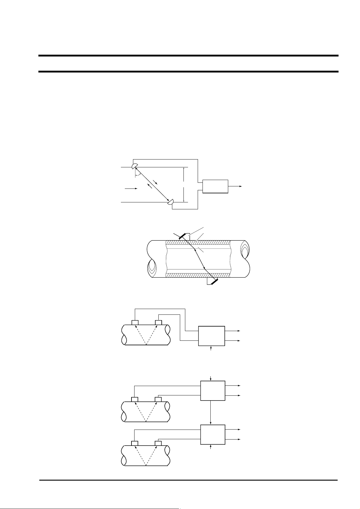
1.1.1. Measuring principle
Measuring principle
Ultrasonic pulses are propagated aslant from the upstream and downstream sides, and the time difference caused by the
flow is detected to measure the flow rate.
Detector
Upstream sensor
θ
Flow velocity
Downstream sensor
t
2
t
1
D
Flow
transmitter
Output signal
Mounting the detector
Configuration diagram
Ultrasonic transducer Pipe
Plastic wedge
Lining
(1) Single-path system (V method)
Special signal cable
(2) When synchronizing
INF-TN1FLRS-E
Detector
Detector
Detector
Special signal cable
Synchronizing
signal wiring
Special signal cable
Flow
transmitter
Power supply
Power supply
Flow
transmitter
(master)
Flow
transmitter
(slave)
Power supply
4 to 20mA DC
Contact
4 to 20mA DC
Contact
4 to 20mA DC
Contact
-1-
Page 10
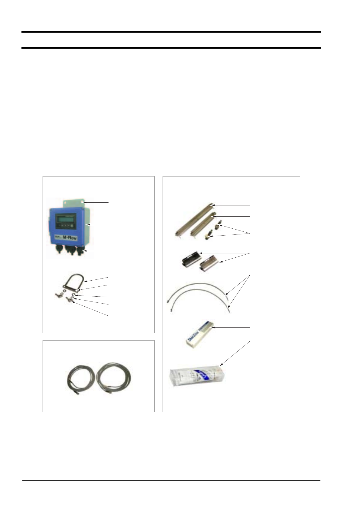
1.2. Checking the received products
Flow transmitter (FLR)
•
Flow transmitter unit ·····································································1 set
Waterproof gland···········································································1 set (mounted on main unit)
Wall mounting fixture····································································1 set (mounted on main unit)
Pipe mounting fixture (option) ······················································1 set
(U bolt, support fixture, 2 wing nuts, 2 spring washers, 2 plain washers)
Detector (FLS)
•
Frame····························································································1 pc
Sensor unit ····················································································1 set (2 pcs)
Stainless steel belt ·········································································1 set (FLSE12: 2 pcs. FLSE22: 4 pcs.)
Spring fixture ················································································2 pcs
Silicone rubber or silicone-free compound (option)·······················1 pc
Signal cable (FLY: length designated) ············································1 set (2 pcs)
•
Instruction manual ·········································································1 copy
•
Belt tightening tool (option)···························································As ordered
•
Flow transmitter (FLR)
Wall mounting fixture
Flow transmitter
unit
Detector (FLS)
Frame for middle size
(FLSE22)
Frame for small size
(FLSE12)
Sensor unit
Waterproof gland
Pipe mounting fixture (option)
U bolt
Support fixture
Plain washer
Spring washer
Wing nut
Signal cable (FLY)
Spring fixture
Stainless steel belt
Silicone rubber
(option)
Silicone-free
grease
(option)
- 2 -
INF-TN1FLRS-E
Page 11
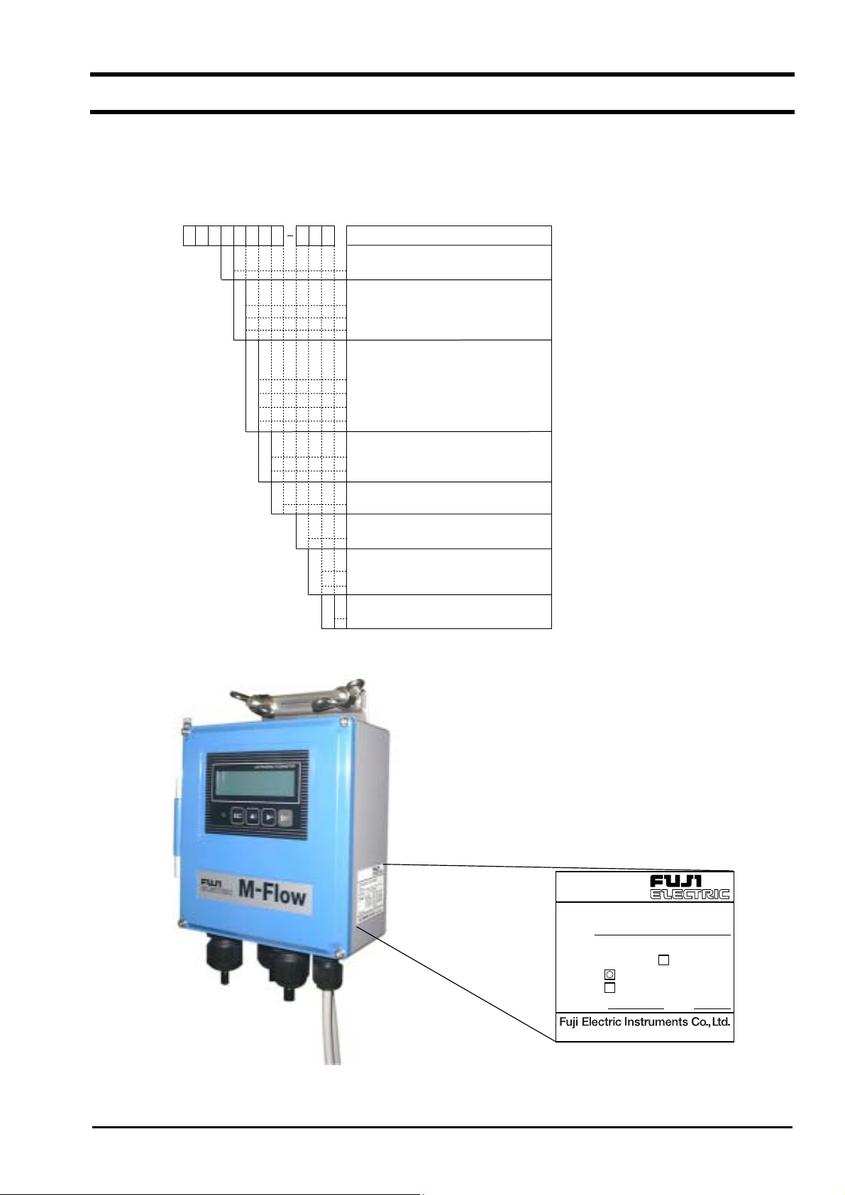
1.3. Checking the type and specifications
The type and specifications of product are indicated on the specifications plate mounted on the flow transmitter and
detector frame. Make sure the types are as ordered referring to the type diagrams given below.
<Flow transmitter>
12345678 91011
2
3
4
Y
A
B
C
11Y
Y
A
1
1
A
B
Type (4th digit)
Standard for exports
Power Supply (5th digit)
100 to 120Vac, 50/60Hz
200 to 240Vac, 50/60Hz
20 to 30V DC
Communication &
Synchronization (6th digit)
None
RS-232C
RS-485 & Synchronization
Synchronization
Arrester (7th digit)
None
With arresters for outputs
Modification No. (8th digit)
Mark 1
Case structure (9th digit)
Immersion-proof (IP65)
Mounting bracket (10th digit)
For 2B pipe mount
For wall mount
Option (11th digit)
Y
None
F
LRE
E
Description
INF-TN1FLRS-E
Ultrasonic Flow Meter
FLRS2YY1-1BY
Type
Output
Power Supply
Ser.No.
DC4-20mA
DC20-30V
AC100-120V 50/60Hz
AC200-240V 50/60Hz
2001
Mfd.
Made in Japan
-3-
Page 12
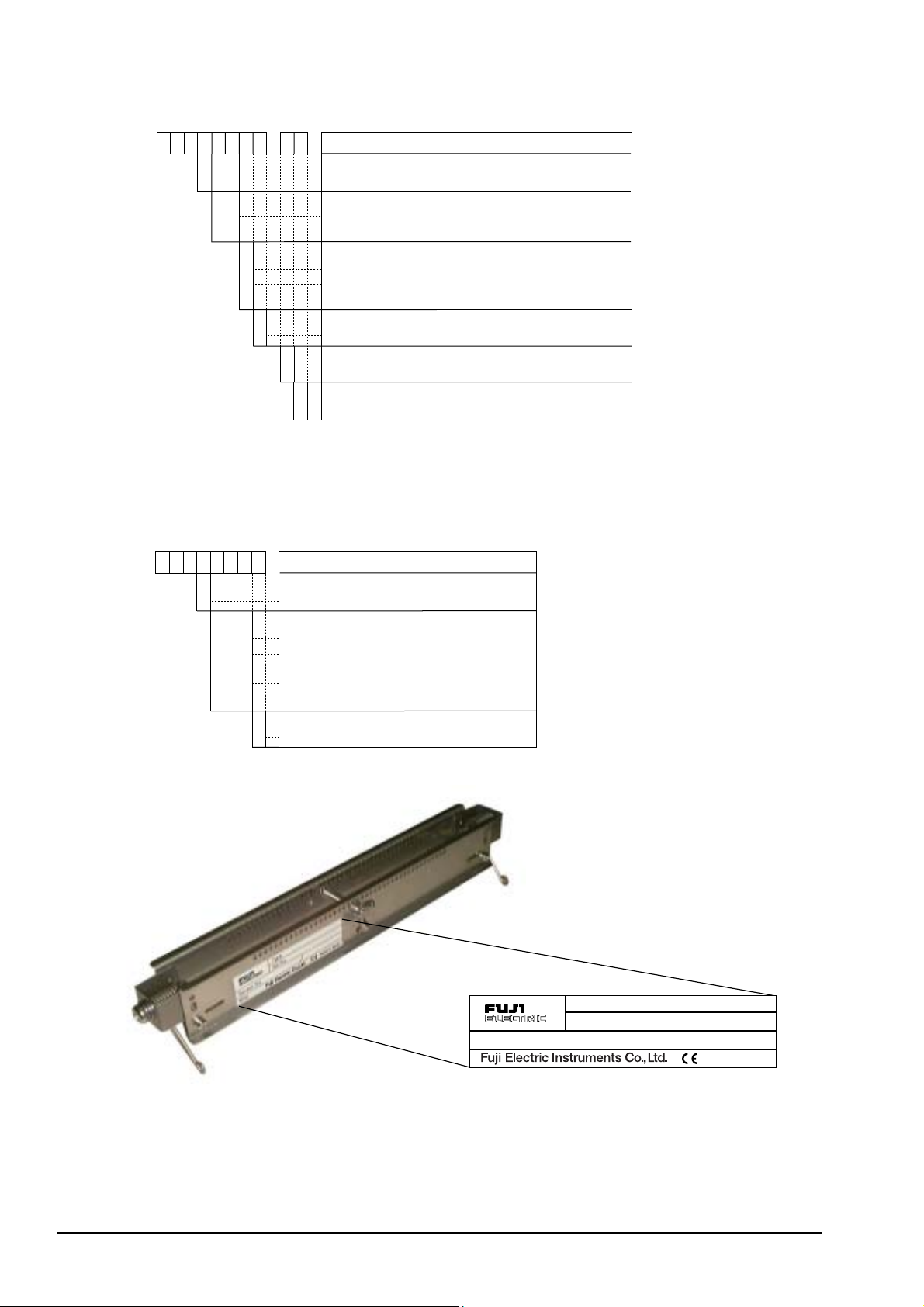
<Detector>
12345678 910
F
LSE
12YY
Type (4th digit)
E
1
2
2
2
Y
A
B
1
Y
Standard
Kind of detector (5th to 6th digit)
Small size detector (for 25 to 100mm)
Middle size detector (for 50 to 225mm)
Acoustic coupler (7th digit)
None
Silicon rubber (fluid temperature: -20 to +100 deg.C)
Silicon-free grease (fluid temperature: 0 to 60 deg.C)
Modification No. (8th digit)
Mark 1
Mounting method (9th digit)
Standard (V-mount)
Option (10th digit)
Y
None
Description
<Signal cable>
12345678
F
LY
3
13
Kind of cable (4th digit)
Heat resisting cable with water-proof BNC
5
0
0
0
1
0
5
0
1
0
2
0
3
0
0
Cable length (5th to 7th digit)
5m (one pair)
10m (one pair)
15m (one pair)
20m (one pair)
30m (one pair)
Modification No. (8th digit)
1
Mark 1
Description
- 4 -
Sensor.No.
Type.
Ser.No.
FLSS12Y1-YY
2001
Mfd.
Made in Japan
INF-TN1FLRS-E
Page 13
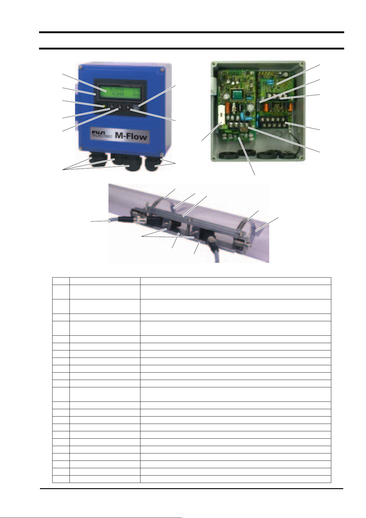
1.4. Names and functions of each part
15
9
3
4
8
14
12
5
6
1
23
18
22
19
7
13
2
16
20
17
19
20
21
No. Name Description
1 Wiring connection port,
For power cable, output cable
large
2 Wiring connection port,
Wiring connection port for signal cable only
small
3 Indication and setting unit Indicates and sets the flow rate, etc.
4 Received wave diagnostic
Indicates whether received wave is normal (green) or abnormal (red).
indication
5 Escape key Return to the next-higher layer or cancels the set status.
6 UP key Selects items, numeric values and symbols.
7 Shift key Moves the cursor and selects decimal place.
8 Entry key Enters a selection or registers a setting.
9 LCD indication Indicates the flow rate or setting.
10 Power terminals Power cable are connected.
11 Input/output terminals Special signal cable, analog output and DO output cables are connected.
12 Communication board
Communication cable is connected (communication board is optional).
terminals
13 Fuse holder Houses a fuse.
14 Relay For DO2 output
15 Communication board Mounted if communication synchronization is optionally designated.
16 Arrester board Board for output mounted if arrester is optionally designated.
17 Frame Fastens the sensor unit on pipe.
18 Sensor unit Sends and receives an ultrasonic wave.
19 Stainless steel belt Fastens the frame on pipe.
20 Spring fixture Removes the play of stainless steel belt.
21 Scale For reading the sensor mounting spacing
22 Fastening hole For positioning and fastening the sensor units
23 Special signal cable Transmits send/receive signals.
11
10
INF-TN1FLRS-E
-5-
Page 14
2. SELECTION OF INSTALLATION PLACE
Select an installation place taking into account the following matters from the viewpoint of easiness of maintenance and
checkup, instrument life and securing the reliability.
(1) A place where ambient temperature and humidity are -20 to +50°C and 90% RH or less for flow
transmitter (FLR), and -20 to +60°C and 90% RH or less for detector (FLS).
(2) A place not exposed to direct sunshine nor weathering.
(3) Sufficient space for daily inspection, wiring, etc.
(4) A place not subjected to radiated heat from a heating furnace, etc.
(5) A place not subjected to corrosive atmosphere.
(6) A place not to be submerged.
(7) A place free from excessive vibration, dust, dirt and moisture.
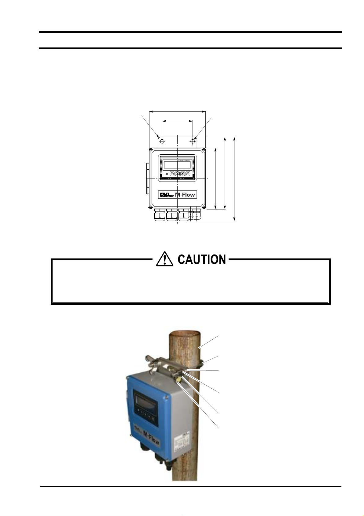
2.1. Flow transmitter
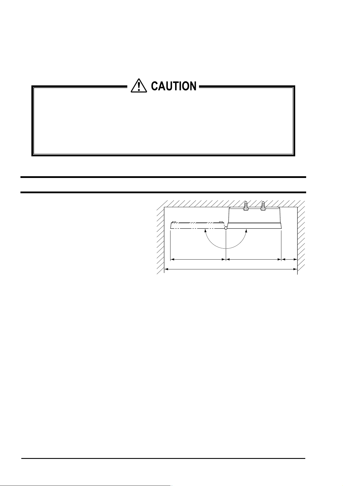
CAUTION
Secure at least 100 mm of space between the flow
transmitter and nearby wall. Also secure a space
of opening the front cover for maintenance.
Secure a cable wiring space under the case.
N
E
P
O
133 100133
370 min.
Top view of mounting
min.
- 6 -
INF-TN1FLRS-E
Page 15
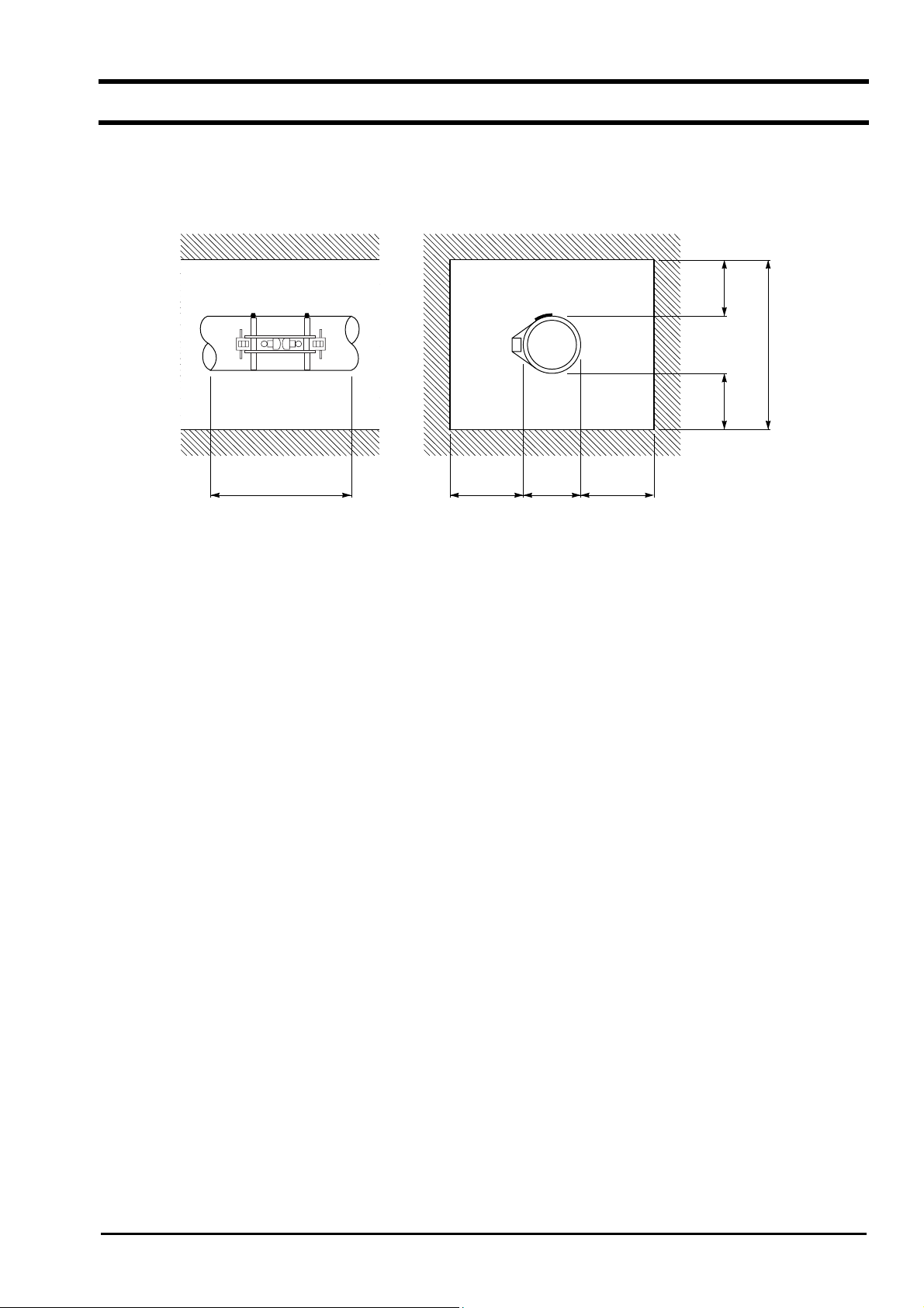
2.2. Detector
The measuring accuracy is considerably affected by the detector mounting place, i.e., status of piping for measuring a flow
rate. Select a place which clears the condition in section 2.2.1. (Length of straight pipe). Also, sufficiently secure a
space for installation and maintenance referring to the following diagram.
2000min.
Note
200min. 200min.
D + 1200 min. 600min. D 600min.
D: Pipe diameter
Necessary space for detector mounting place
INF-TN1FLRS-E
-7-
Page 16
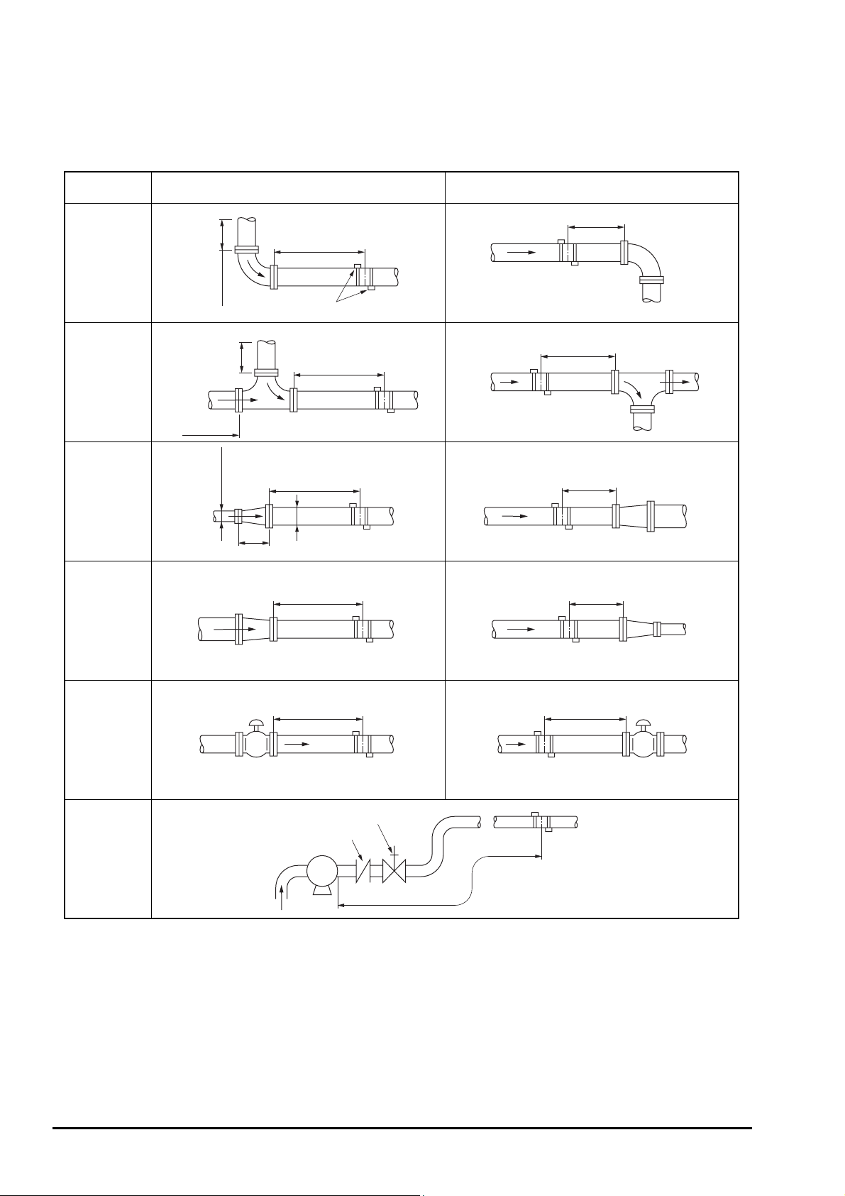
2.2.1. Length of straight pipe
The length of upstream and downstream straight pipe of the ultrasonic detector should be long enough to ensure accurate
measurements.
(D: Nominal diameter of pipe)
Name Straight length of upstream piping Straight length of downstream piping
L≥5D
L≥10D
90° bend
Tee
Diffuser
Reducer
10D min.
0.5D min.
10D min.
10D min.
1.5D min.
Detector
L≥50D
L≥30D
D
L≥10D
L≥10D
L≥5D
L≥5D
Valve
Pump
Note: Quoted from JEMIS-032
L≥30D
Flow controlled upstream
Check valve
Stop valve
P
L≥10D
Flow controlled downstream
L≥50D
- 8 -
INF-TN1FLRS-E
Page 17
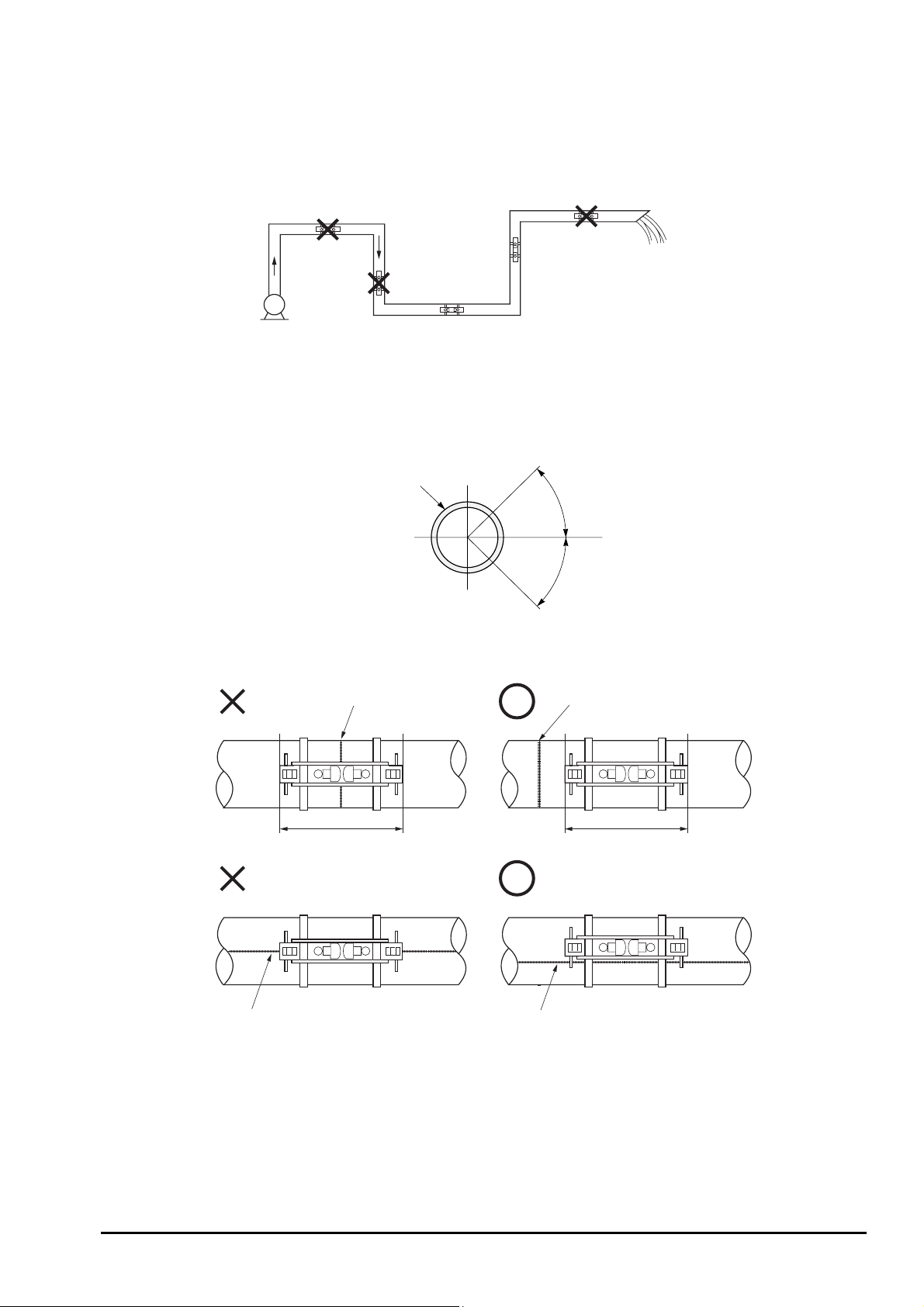
2.2.2. Mounting posture
The detector can be installed vertical, horizontal or at any posture provided that attention is paid to the following things.
(1) The piping must completely be filled with fluid when it flows.
Air tends to accumulate.
May not
completely be
filled with liquid.
May not completely be filled with liquid.
Good
Pump
Good
(2) In case of horizontal piping, mount the detector within ±45° from the horizontal plane. Otherwise, the measurement
could be impossible if bubbles stay in the upper part of piping or if deposits are accumulated in the lower part of
piping. In case of vertical piping, the detector may be mounted at any position on its periphery provided that the
flow is upward.
Pipe
45°
Horizontal
45°
(3) Do not mount the detector on a distorted part, flange or welding.
Weldment
Weldment
INF-TN1FLRS-E
Welding is included.
Welding is partly involved. Avoid Welding.
Off the Welding.
-9-
Page 18

3. INSTALLATION AND PROCEDURE PRIOR
TO RUNNING
3.1. Outline of installation procedure
(1) Select the flow transmitter and detector installation places.
(2) Install and wire the flow transmitter.
(3) Turn on power.
(4) Set the piping parameters, and calculate the sensor unit spacing (* if with parameter setting, check the sensor unit
spacing).
(5) Mount the frame on the piping to measure on.
(6) Mount the sensor unit.
(7) Set the measurement range (* unnecessary if with parameter setting and if measurement range is designated).
(8) Adjust zero point.
(9) Start a measurement.
- 10 -
INF-TN1FLRS-E
Page 19
3.2. Installation of flow transmitter
The flow transmitter may be mounted on a wall or 2B pipe stand (option).
3.2.1. Wall mounting
For wall mounting, use two M8 bolts.
According to the mounting hole dimensions shown below, drill holes on the wall, and tighten M8 bolts.
Mounting
plate
130
70
Mounting hole 2-φ9
170
140
(197)
3.2.2. 2B pipe stand mounting
CAUTION
When mounting on 2B pipe, be sure to use a complete set of fixtures (U bolt, support fixture, plain washer,
spring washer, wing nut) furnished if optionally designated. Tighten the wing nut by hand. If any support
fixture is not used or if the altogether is excessively tightened by tool, the wall mounting fixture may be
deformed, thereby breaking the resin case.
Mount the instrument on 2B pipe stand as illustrated below.
2B pipe stand
U bolt
Support fixture
Plain washer
Spring washer
INF-TN1FLRS-E
Wing nut
-11-
Page 20
3.3. Flow transmitter wiring
3.3.1. Precautions in wiring
CAUTION
(1) Use a special coaxial cable (FLY3) as a signal cable between the detector (FLS) and flow transmitter
(FLR). Do not provide a junction of the signal cable midway.
(2) Be sure to pass the signal cables through a metal conduit between the detector and flow transmitter.
Upstream and downstream signal cables may be put in the same conduit but, to avoid an interference, do
not put the power cable together.
(3) For output signal, use a shield cable, where possible.
(4) To avoid ingress of noise, do not put the cables together with heavy duty line or the like into the same
duct.
(5) If a ground wire is included in the power cable, connect it to ground as it is.
(6) A power switch is not provided on the instrument and must be mounted separately.
(7) Hermetically cover unused wiring ports by furnished caps.
3.3.2. Applied wiring
Use the following cables.
Power cable : 3 or 2 core cabtyre cable.
z
Nominal cross-sectional area 0.75 mm
Finish outer diameter ∅11 mm.
Output signal cable : 2 or, as required, multiple core cabtyre cable.
z
Finish outer diameter ∅11 mm.
Detector-flow transmitter cable : Special signal cable by type designation (heat-resisting high-frequency coaxial cable
z
having 50 Ω of characteristics impedance, provided on a side with waterproof BNC
connector).
Finish outer diameter ∅5 mm.
2
min.
3.3.3. Treatment of wiring ports
The outer case of flow transmitter is waterproof (IP65). However, if installed in a humid place, the wiring ports must be
made airtight to avoid ingress of moisture, condensation, etc. Be sure to use the waterproof glands furnished with the
instrument in order to ensure the waterproof means. Hermetically seal unused glands by furnished caps.
CAUTION
Do not install the instrument where there is a risk of inundation.
- 12 -
INF-TN1FLRS-E
Page 21
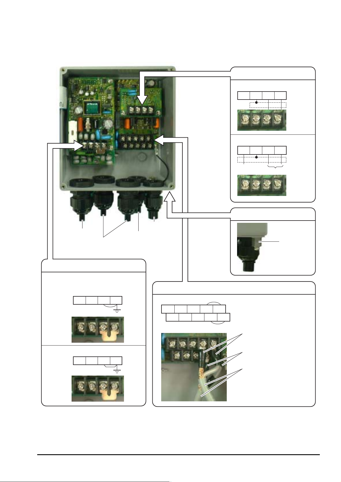
3.3.4. Wiring to each terminal
Refer to the following diagram for carrying out wiring.
Communication board terminal block (option)
RS-232C
NC
GND RXD TXD
RS-485 and synchronization
SYNC
SHILD TXDR2 TXDR1
Power cable
Output signal cable
(analog output, DO1, DO2,
communication synchronization)
Downstream
sensor cable
Power board terminal block
AC power source: 100 to 120 or 200 to 240 V AC,
50/60 Hz
LN
GND GND
Upstream
sensor cable
Main board terminal block
Iout(+) DO1(+) DO2(+) GND HF1
Iout(-) DO1(-) DO2(-) GND HF2
Upstream sensor
Downstream sensor
Synchronization
RS-485
External ground terminal
Ground terminal
Red (upstream sensor)
DC power source: 20 to 30V DC
+−
GND GND
Black (downstream sensor)
Special signal cable (FLY3)
Iout : Analog output
DO1: Transistor open collector
DO2: Relay contact
Notes
1. All screws are M3 on the terminal block. Use crimp-style terminals for M3 and whose outer diameter is ∅5.8 or
smaller.
2. Be sure to connect to ground the power board terminal block or external ground terminal (class D ground).
3. For output signal, use multiple core cable as required.
INF-TN1FLRS-E
-13-
Page 22
3.4. Setting the piping parameters and calculating the
sensor unit spacing
After installation and wiring of the flow transmitter (sensor unit may not be wired), turn on power, input the piping
parameters below, and calculate the sensor unit installation spacing. (*When it is provided with parameter setting, the
following parameters have already been input. Check the installation spacing in this case.)
Item Input
method
Pipe outer diameter Value 10 to 300mm
Pipe material Menu PVC, PVDF, PEEK, PP, CARBON STEEL, STAINLESS STEEL, COPEER,
PIPE S.V (Note 1)
Pipe wall thickness Value 0.1 to 100mm
Lining presence and
material selection
Lining thickness Value 0.1 to 10mm
Fluid type Selection Water, sea water, FLUID S.V (Note 1)
Kinematic viscosity Value 0.00E-6m2/s to 999.999E-6m2/s (Note 1)
Note 1: In case of material or fluid not included in menus, input its sound velocity and kinematic viscosity of the
fluid. The sound velocity can be inputted within the range of 1000 to 3700 m/s for piping or lining
material, or 500 to 2500m/s for fluid. (Refer to section 6.6.)
The operating procedure is as follows (from measurement mode).
Note 2: If the parameter protection is set at "PROTECTION ON", change it to "PROTECTION OFF". If ID NO.
is set at this time, ID NO. must be inputted.
Keying
key pressed 3 times.
Menu NO LINING, TAR EPOXY, MORTAR, RUBER, TEFLON, PYREXGLASS,
LINING S.V (Note 1)
1st line: [MEASURE SETUP].
Range or menu
LCD indication/comment
ENT
key pressed.
key pressed 3 times.
ENT
key pressed.
ENT
key pressed.
ENT
ENT
ENT
ENT
and
pressed to enter.
key pressed.
key pressed.
key pressed to select.
key pressed to enter.
key pressed.
key pressed.
key pressed.
1st line: [SYSTEM UNIT].
1st line: [PIPE PARAMETER].
1st line: [OUTER DIAMETER]. 2nd line: [60.00 mm]. * As selected currently.
Cursor blinks on 2nd line.
Input the outer diameter of a measurement pipe. As necessary, check the piping data
in section 6.6.
: Selects a numeric. : Shifts the place.
Registered after [**COMPLETE**] is indicated about 1 second on 2nd line.
1st line: [PIPE MATERIAL]. 2nd line: [PVC] * As selected currently.
Cursor blinks on 2nd line.
Select the pipe material from menus. If there is no corresponding menu, input the
sound velocity of pipe material on sound velocity input screen whose menu is located
at the last. As necessary, see piping data in section 6.6.
Registered after [**COMPLETE**] is indicated about 1 second on 2nd line.
1st line: [WALL THICKNESS]. 2nd line: [4.50mm] * As selected currently.
Cursor blinks on 2nd line.
ENT
- 14 -
and
key pressed to enter.
key pressed.
Input the wall thickness of a measurement pipe. As necessary, check the piping data
in section 6.6.
: Selects a numeric. : Shifts the place.
Registered after [**COMPLETE**] is indicated about 1 second on 2nd line.
INF-TN1FLRS-E
Page 23
Keying
key pressed.
ENT
key pressed.
key pressed to select.
ENT
key pressed to enter.
key pressed.
ENT
key pressed.
ENT
ENT
ENT
and
key pressed to enter.
key pressed.
key pressed.
key pressed to select.
key pressed to enter.
key pressed.
LCD indication/comment
1st line: [LINING MATERIAL]. 2nd line: [NO LINING]. * As selected currently.
If pipe is not lined, press key to go to selection of next fluid to be measured.
Cursor blinks on 2nd line.
Select the lining material from menus. If there is no corresponding menu, input the
sound velocity of lining material on sound velocity input screen whose menu is located
at the last. As necessary, see lining data in section 6.6.
Registered after [**COMPLETE**] is indicated about 1 second on 2nd line.
1st line: [LINING THICKNESS]. 2nd line: [2.00 mm]. * As selected currently.
Note: Not indicated if lining material is set at [NO LINING].
Cursor blinks on 2nd line.
Input the lining thickness.
: Selects a numeric. : Shifts the place.
Registered after [**COMPLETE**] is indicated about 1 second on 2nd line.
1st line: [KIND OF FULID]. 2nd line: [WATER]. * As selected currently.
Cursor blinks on 2nd line.
Select [WATER] or [SEA WATER]. In case of other fluid, input the sound velocity of
fluid on sound velocity input screen whose menu is located at the last. As necessary,
see piping data in section 6.6.
Registered after [**COMPLETE**] is indicated about 1 second on 2nd line.
key pressed.
ENT
key pressed.
ENT
ENT
ENT
ESC
ESC
and
key pressed to enter.
key pressed twice.
key pressed.
key pressed.
key pressed to enter.
key pressed.
key pressed.
key pressed twice.
key pressed.
1st line: [KINEMATIC VISCO]. 2nd line: [1.0038E-6m2/s]. * As selected
currently. Kinematic viscosity of water is factory set. If fluid to be measured is
other than water, input the kinematic viscosity referring to piping data in section 6.6.
Cursor blinks on 2nd line.
Input the kinematic viscosity.
: Selects a numeric. : Shifts the place.
Registered after [**COMPLETE**] is indicated about 1 second on 2nd line.
1st line: [SENSOR TYPE]. 2nd line: [FLS_12]. * As selected currently.
Cursor blinks on 2nd line.
Select [FLS_12] or [FLS_22].
Registered after [**COMPLETE**] is indicated about 1 second on 2nd line.
1st line: [PIPE PARAMETER]. 2nd line: [S= 16 ( 48mm)] (*).
* Sensor unit spacing calculated by above setting is indicated for sensor unit
spacing at detector installation.
1st line: [MEASURE SETUP]
Measurement mode is resumed.
INF-TN1FLRS-E
-15-
Page 24
3.5. Installation of detector
3.5.1. Outline of detector installation procedure
(1) Treat the surface to mount on the detector.
(2) Mount the frame.
(3) Mount the sensor unit.
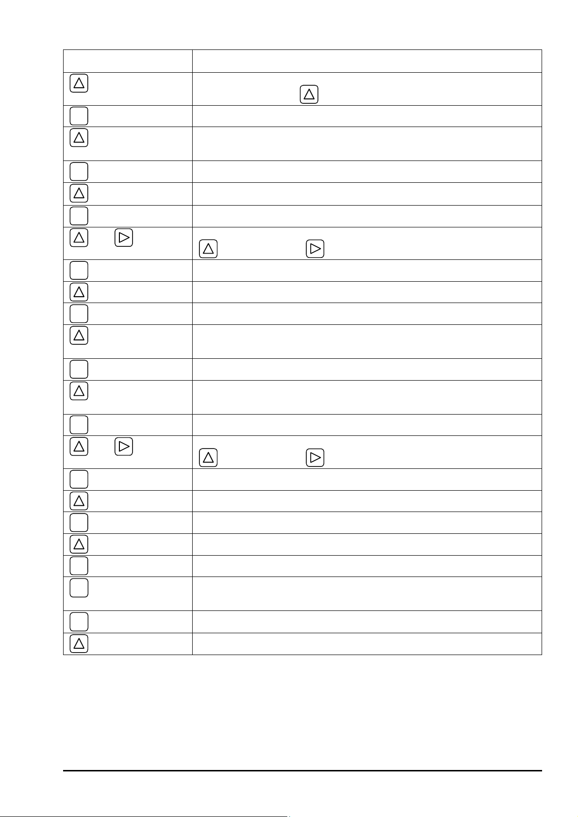
3.5.2. How to treat the mounting surface
By thinner, sandpaper, etc., eliminate rust, pitch, convex and concave from the pipe surface to mount on the detector by the
frame length to occupy.
Note: 1. If jute is wound on the pipe, peel off the jute over the entire periphery by frame length (L) + 200 mm
beforehand.
Jute winding
Pipe
L+200mm
Fig. 3-1 L: Frame length (FLSE1: 240 mm, FLSE2: 360 mm)
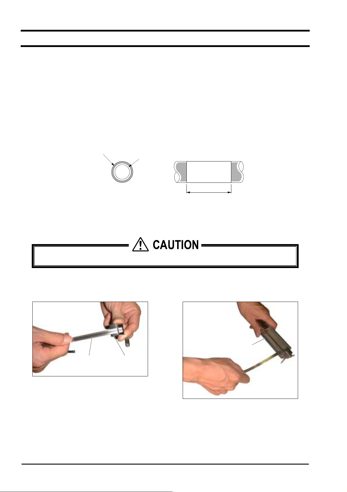
3.5.3. How to mount the frame
CAUTION
Mount the frame carefully not to cut your fingers with stainless steel belt.
z
(1) Pass the spring fixture on the stainless steel belt as
shown in Fig. 3-2.
Spring fixtureStainless steel belt
Fig. 3-2
(2) Pass the stainless steel belt through 2 belt holes on
the frame as shown in Fig. 3-3.
Frame
Fig. 3-3
- 16 -
INF-TN1FLRS-E
Page 25
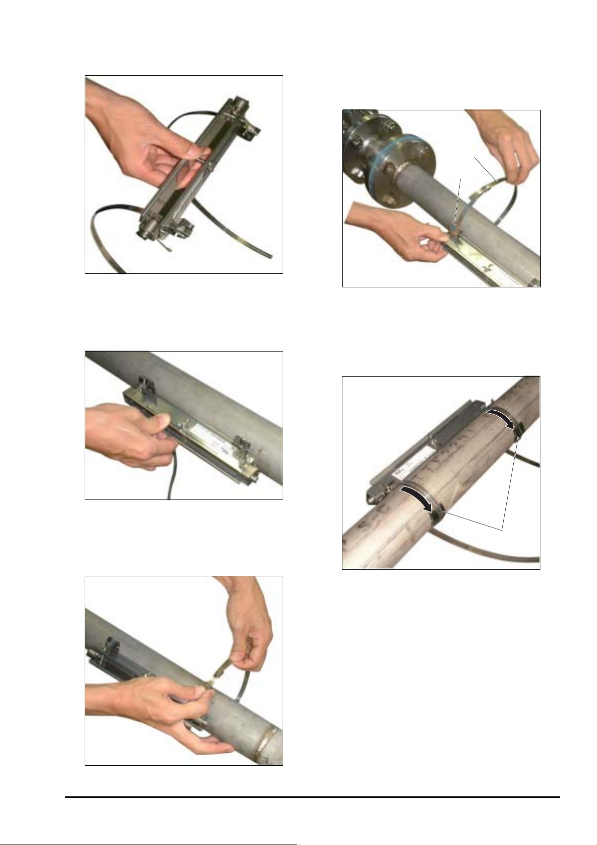
(3) Make sure the obtained status is as shown in Fig. 3-4.
Fig. 3-4
(4) As shown in Fig. 3-5, apply the frame on the pipe
section subjected to a surface treatment.
(6) Adjust the frame so as to be in parallel with the pipe,
put the spring fixture to the side of the frame as
shown in Fig. 3-7, and tighten the stainless steel belt
so that the frame will tightly be fitted.
Second
stainless
steel belt
Spring fixture
Fig. 3-7
(7) After tightening both stainless steel belts, slide the
spring fixture to the opposite to the frame as shown in
Fig. 3-8.
Fig. 3-5
(5) Temporarily tighten the first stainless steel belt on the
pipe as shown in Fig. 3-6.
Spring fixture
Fig. 3-8
Note: When removing the frame set to the piping and
set it to a different position, use new stainless
steel belts.
INF-TN1FLRS-E
Fig. 3-6
-17-
Page 26
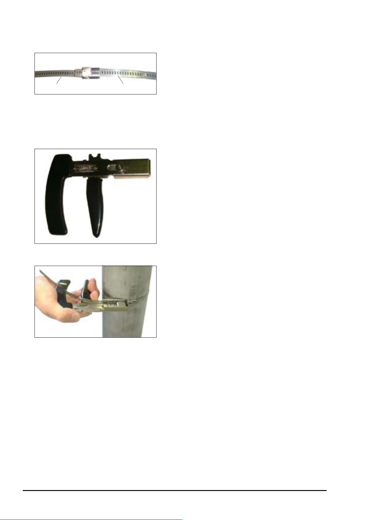
Mounting on pipe whose diameter is 150A or larger
As shown in Fig. 3-9, connect 2 stainless steel belts.
First steel belt Second steel belt
Fig. 3-9
Tightening tool
Use of an optional tool (Fig. 3-10) facilitates tightening
the stainless steel belt (Fig. 3-11).
Fig. 3-10
Fig. 3-11
- 18 -
INF-TN1FLRS-E
Page 27
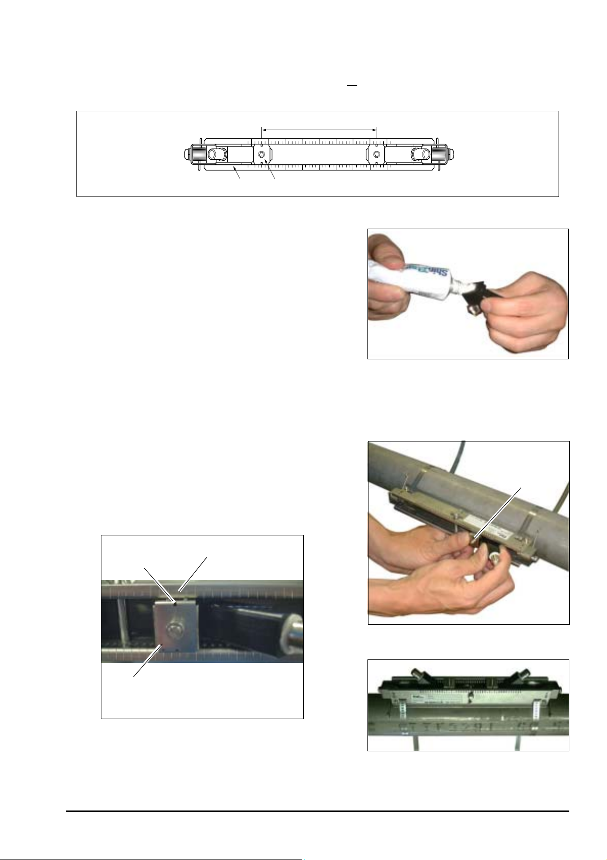
A
3.5.4. How to mount the sensor unit
(1) Mount both sensor units spaced at the SPACING value [S= **] (number of graduations on frame) indicated after
setting the piping parameters.
Mounting size (SPACING)
Pressing fixture
Frame
Fig. 3-12
(2) Before mounting the sensor unit into the frame, sufficiently
apply silicone filler (or silicone-free grease
entire transmission surface of the sensor unit, taking care not
to introduce bubbles (Fig. 3-13).
Note) When using silicon-free grease, pay attention to the
fluid temperature range. The fluid temperature range
is shown below.
Silicon rubber: −20 to 100°C
Silicon-free grease: 0 to 60°C
When using silicon-free grease, reapply it on the
transmission surface of the sensor unit approximately
once every 6 months. (Silicon rubber need not be
reapplied.)
(3) Then insert the sensor unit into the frame, align the slit
provided on the pressing fixture of the sensor unit with
graduations located on the frame top surface (see Fig. 3-14),
and press the sensor unit until the fixture claws are engaged
with the frame side square holes. Mount both sensor units
so as to be roughly symmetrical with respect to the frame
(see Fig. 3-15).
Graduations
Slit
Note
) over the
Fig. 3-13
Pressing fixture
INF-TN1FLRS-E
Position of the slit and the graduation
(Magnified view of section A)
Fig. 3-14
Fig. 3-15
-19-
Page 28
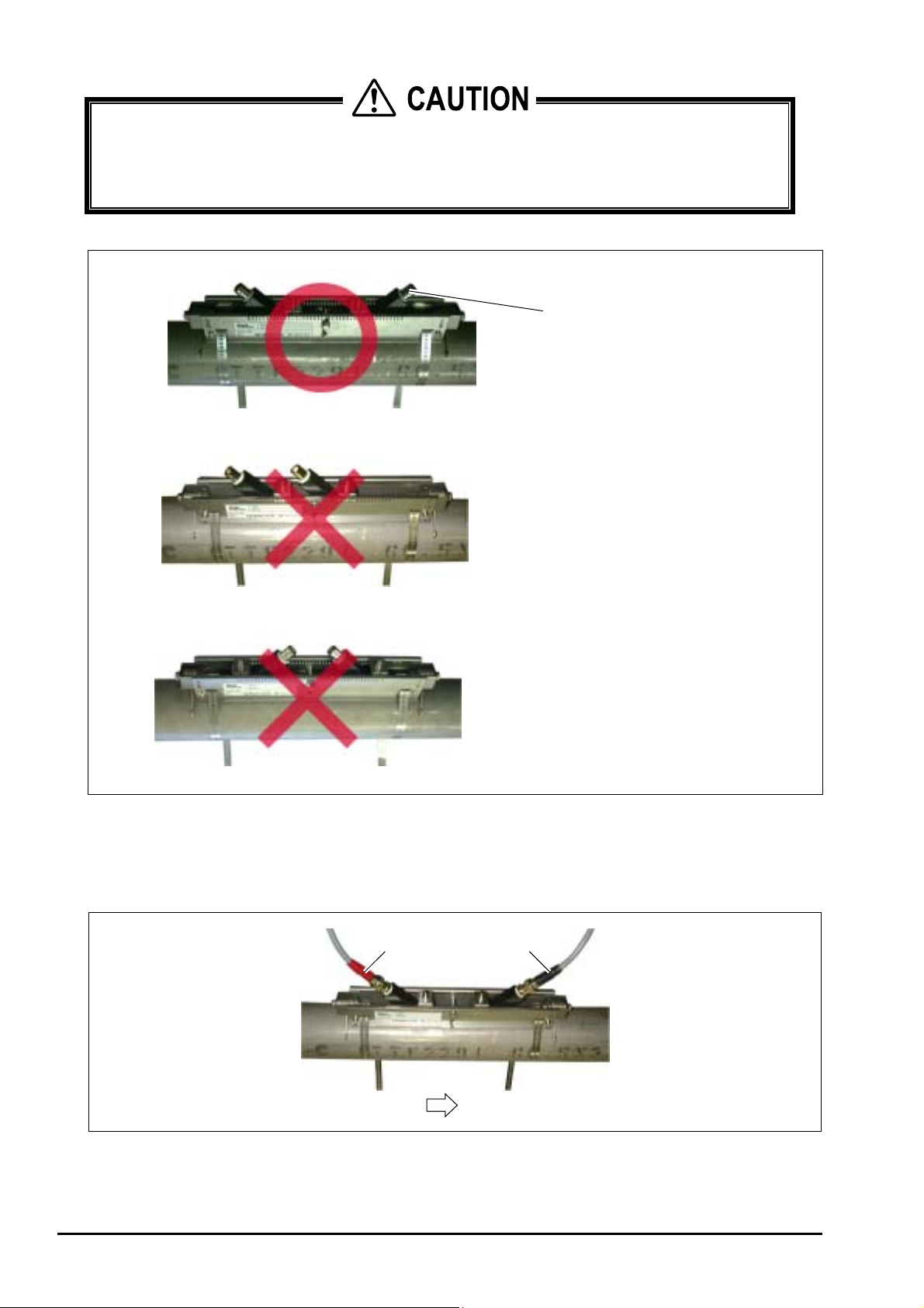
CAUTION
Mount the sensor units so that their BNC connectors will face outward (Fig. 3-16a). If at least one is
mounted opposite, the measurement is impossible (Fig. 3-16b, c). The pressing fixture claws must
completely be engaged with square holes provided on sides of the frame. Otherwise, the sensor and pipe will
not correctly get in contact with each other, whereby the measurement will be impossible.
BNC connector (must face outward)
Mount the BNC connectors of sensor units
so as to face outward
Fig. 3-16 a
Do not mount the BNC connectors of sensor units
in the same direction
Fig. 3-16 b
Do not mount the BNC connectors of sensor units
so as to face inward
Fig. 3-16c
Fig. 3-16
(4) Engage the signal line with BNC connectors of the sensor units. At this time, do not mistake the upstream and
downstream sides for each other. Engage the red BNC connector upstream, and the black BNC connector
downstream (see Fig. 3-17).
Red Black
- 20 -
Upstream
Downstream
Fig. 3-17
INF-TN1FLRS-E
Page 29
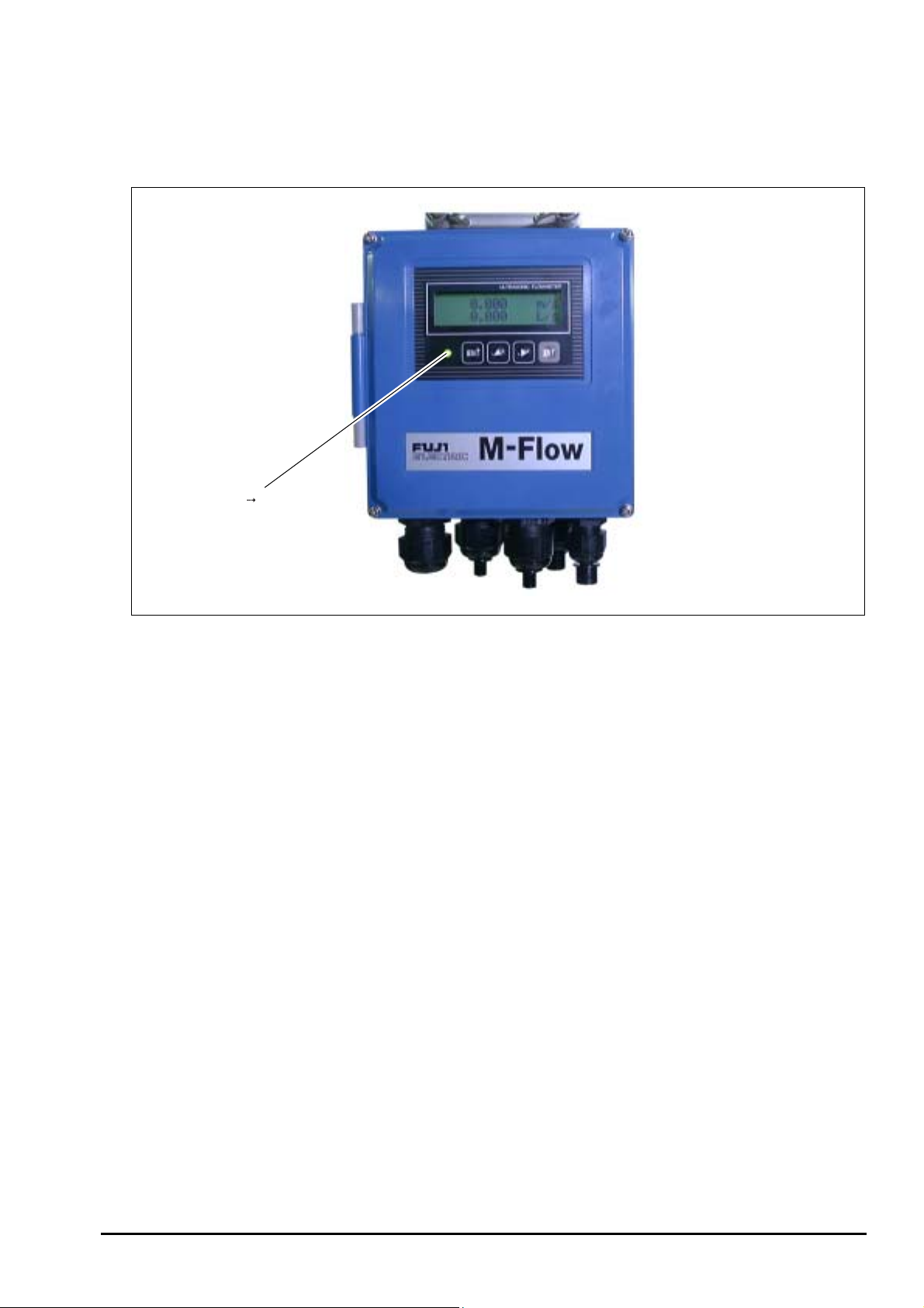
(5) After connecting the signal line, make sure the red LED on the flow transmitter has turned green. It takes about
10 seconds until the color changes to green.
The green color indicates the received signal is normal. The red color indicates the received signal is abnormal. If
the LED remains red and does not turn green, examine the sensor installation status (sensor spacing, sensor
orientation, claw engagement, etc.) and parameter settings, and check whether the piping is filled with fluid.
LED (red " green)
Fig. 3-18
INF-TN1FLRS-E
-21-
Page 30
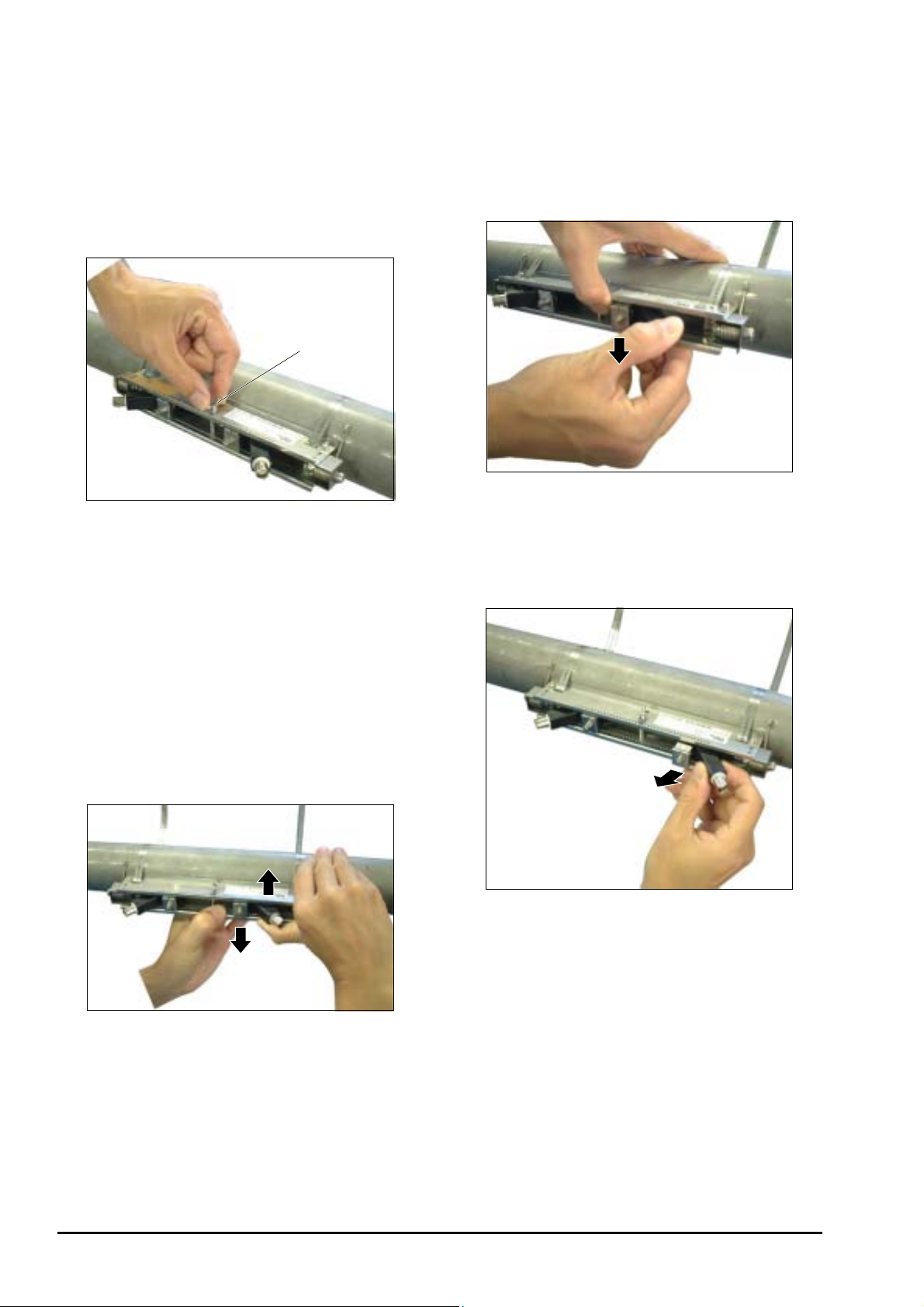
3.5.5. How to remove the sensor unit
If the sensor unit has to be detached from the frame such as after mistaking the space between the sensor units, proceed as
follows.
(1) Loosen the wind bolt located at the middle of frame
by 3 to 4 turns (Fig. 3-19).
Note 1: Do not loosen the wing bolt completely.
(3) Likewise, disengage the opposite claws of the sensor
unit pressing fixture from the frame (Fig. 3-21).
Wing bolt
Fig. 3-19
(2) By hand, hold the frame near the pressing fixture for
a sensor unit to remove.
Press the resin section which stands out of the frame
of sensor unit just enough to open the frame a little
(about 1 mm). At this time, the claws of sensor unit
fixture are disengaged from the frame (Fig. 3-20).
Note 2: Do not open the frame excessively. Otherwise,
it may deform, and an accurate measurement
could be impossible or the sensor unit could
not be installed.
Fig. 3-21
(4) Making sure claws have been disengaged from both
sides, and pull out the sensor unit from the frame (Fig.
3-22).
- 22 -
Fig. 3-20
(5) In the same procedure, remove the other sensor unit
also.
Note 3: After removing both sensor units, tighten the
loosened wing bolt as before.
Fig. 3-22
INF-TN1FLRS-E
Page 31

3.6. Setting the range and total pulse output
The range is set in the following procedure.
According to a selected range value, an analog output (4-20 mA DC) is delivered.
A pulse is outputted every time the integrated value attains a pulse value.
(Note: Must be carried out after setting the piping parameters in Section 3.4.)
(1) Selecting a unit system: Metric or inch system
Note: Factory set at "Metric system". If you retains it as it is, go to (2) below.
Proceed to the following from the measurement mode.
Keying LCD indication/comment
key pressed 3 times.
ENT
key pressed.
ENT
key pressed.
1st line: [MEASURE SETUP].
1st line: [SYSTEM UNIT]. 2nd line: [METRIC]. * As selected currently.
2nd line blinks.
key pressed.
ENT
key pressed.
(2) Selecting a flow rate unit: L/s, m3/h or other flow rate unit.
Follows the operation from (1) above.
Keying LCD indication/comment
key pressed 1 times.
ENT
key pressed.
key pressed.
ENT
key pressed.
(3) Selecting a total unit: mL, L, m3, or other total unit.
* Must be selected when total indication or total pulse output is used.
Follows the operation from (2) above.
Keying LCD indication/comment
key pressed 1 times.
Select a unit system out of metric system: [METRIC] and inch system:
[ENGLISH].
Registered after [**COMPLETE**] is displayed about 1 sec on 2nd line.
1st line: [FLOW UNIT], 2nd line: [L/s] * As selected currently.
2nd line blinks.
Repeatedly until a desired flow rate unit is selected.
Registered after [**COMPLETE**] is displayed about 1 sec on 2nd line.
1st line: [TOTAL UNIT], 2nd line: [mL] * As selected currently.
ENT
key pressed.
key pressed.
ENT
key pressed.
ESC
key pressed.
key pressed twice.
* Carrying out the operation in (1) to (3) above completes setting of the unit system, flow rate unit and total unit.
INF-TN1FLRS-E
2nd line blinks.
Repeatedly until a desired total unit is selected.
Registered after [**COMPLETE**] is displayed about 1 sec on 2nd line.
1st line: [MEASURE SETUP]
Resumes the measurement mode.
-23-
Page 32

(4) Setting the range: To full scale.
Proceed to the following from the measurement mode.
Keying LCD indication/comment
key pressed twice.
ENT
key pressed.
key pressed 4 times.
ENT
key pressed.
ENT
key pressed to enter.
ENT
key pressed.
1st line: [OUTPUT SETUP].
1st line: [ZERO ADJUST].
1st line: [RANGE]. 2nd line: [FLOW RATE].
2nd line blinks.
1st line: [FLOW SPAN-1]. 2nd line: [10.0 L/s]. * As selected currently.
Cursor blinks on 2nd line.
and
pressed.
ENT
key pressed.
ESC
key pressed 3 times.
key pressed 3 times.
key
Until the range is set to a desired value. Setting is available from 0.3 to 10 m/s
in terms of velocity.
Operate
to select a numeric or point, and to shift the place.
Registered after [**COMPLETE**] is displayed about 1 sec on 2nd line.
1st line [OUTPUT SETUP].
Resumes the measurement mode.
- 24 -
INF-TN1FLRS-E
Page 33

(5) Setting the total pulse and preset value, and starting the total
Set the pulse value, pulse width and preset value.
Then, reset the total value to a preset value (factory set at 0), and start a total.
Proceed to the following from the measurement mode.
Keying LCD indication/comment
key pressed twice.
ENT
key pressed.
key pressed 4 times
ENT
key pressed.
key pressed.
ENT
key pressed.
key pressed.
ENT
key pressed.
1st line: [OUTPUT SETUP]
1st line: [ZERO ADJUST]
1st line: [RANGE], 2nd line: [FLOW RATE]
2nd line blinks
2nd line: [TOTAL]
1st line: [TOTAL MODE], 2nd line [START]
1st line: [PULSE VALUE], 2nd line: [1mL] * As selected currently.
Cursor blinks on 2nd line.
and
key
pressed for composing a
pulse value.
ENT
key pressed.
key pressed.
ENT
key pressed.
key pressed.
ENT
key pressed.
key pressed.
ENT
key pressed.
and
key
pressed.
ENT
key pressed.
key pressed 3 times.
ENT
key pressed.
Compose a desired pulse value. (See 4.5.6.1)
: Selects a numeric or decimal point. : Shifts the place.
[**COMPLETE**] appears about 1 second on 2nd line, and then pulse value is
registered.
1st line: [PULSE WIDTH]. 2nd line: [5.0 ms]. * As selected currently.
Cursor blinks on 2nd line.
Select 5.0 ms, 10 ms, 50 ms, 100 ms or 200 ms. (See 4.5.6.1)
[**COMPLETE**] appears about 1 second on 2nd line, and then pulse width is
registered.
1st line: [TOTAL PRESET]. 2nd line: [0 mL]. * As selected currently.
Cursor blinks.
Compose a desired preset value.
: Selects a numeric or decimal point. : Shifts the place.
[**COMPLETE**] appears about 1 second on 2nd line, and then preset value is
registered.
1st line: [TOTAL MODE]. 2nd line: [START]. * As selected currently.
2nd line blinks.
key pressed.
ENT
key pressed.
ENT
key pressed.
key pressed twice.
ENT
key pressed.
ESC
key pressed 3 times.
key pressed 3 times.
INF-TN1FLRS-E
2nd line: [RESET]. * Make sure beforehand total value can be reset.
[**COMPLETE**] appears about 1 second on 2nd line, and then total value is
reset.
2nd line: [STOP]. * Total stops.
Cursor blinks on 2nd line.
2nd line: [START].
[**COMPLETE**] appears about 1 second on 2nd line.
2nd line: [START]. * Total starts.
1st line: [OUTPUT SETUP].
Measurement mode is resumed.
-25-
Page 34

3.7. How to calibrate zero
Completely close the valves upstream and downstream the flow meter before calibrating zero.
Notes
1. If there is no valve or if the fluid flow cannot be stopped, select "CLEAR" when "ZERO ADJUST". In this
case, the zero point may slightly be off.
2. If parameters are set at "PROTECTION ON", select "PROTECTION OFF" beforehand.
3. SET ZERO: Retains the current status as zero. CLEAR: Sets the calibration value for zero point to "0".
The following is the zero point adjustment procedure from measurement mode.
Keying LCD indication/comment
key pressed twice.
ENT
key pressed.
ENT
key pressed.
key pressed.
1st line: [OUTPUT SETUP]
1st line: [ZERO ADJUST]. 2nd line: [CLEAR]. * As selected currently.
2nd line blinks.
2nd line: [SET ZERO].
ENT
key pressed to register.
ESC
key pressed.
key pressed 3 times.
On 2nd line about 1 sec, [**COMPLETE**] is displayed, and zero calibration is
performed (Note 4).
1st line: [OUTPUT SETUP]
Measurement mode is resumed.
CAUTION
Note: 4. If [CLEAR] has been selected and executed at this time, a currently stored zero calibration
value will be cleared to zero.
- 26 -
INF-TN1FLRS-E
Page 35

4. PARAMETERS
4.1. Description on display/setting section
The display/setting section is illustrated below.
LED
○ LED display: Indicates whether the received wave is normal or not.
(Green): Received wave is normal.
(Red): Received wave is abnormal.
Set the parameter by setting switches.
ESC
Escape key : Returns to a higher hierarchical rank or cancels the setting status.
UP key : Selects an item, value or symbol.
SHIFT key : Moves the cursor, decimal point, etc.
ENT
Entry key : Enters a selection or registers a setting.
INF-TN1FLRS-E
-27-
Page 36

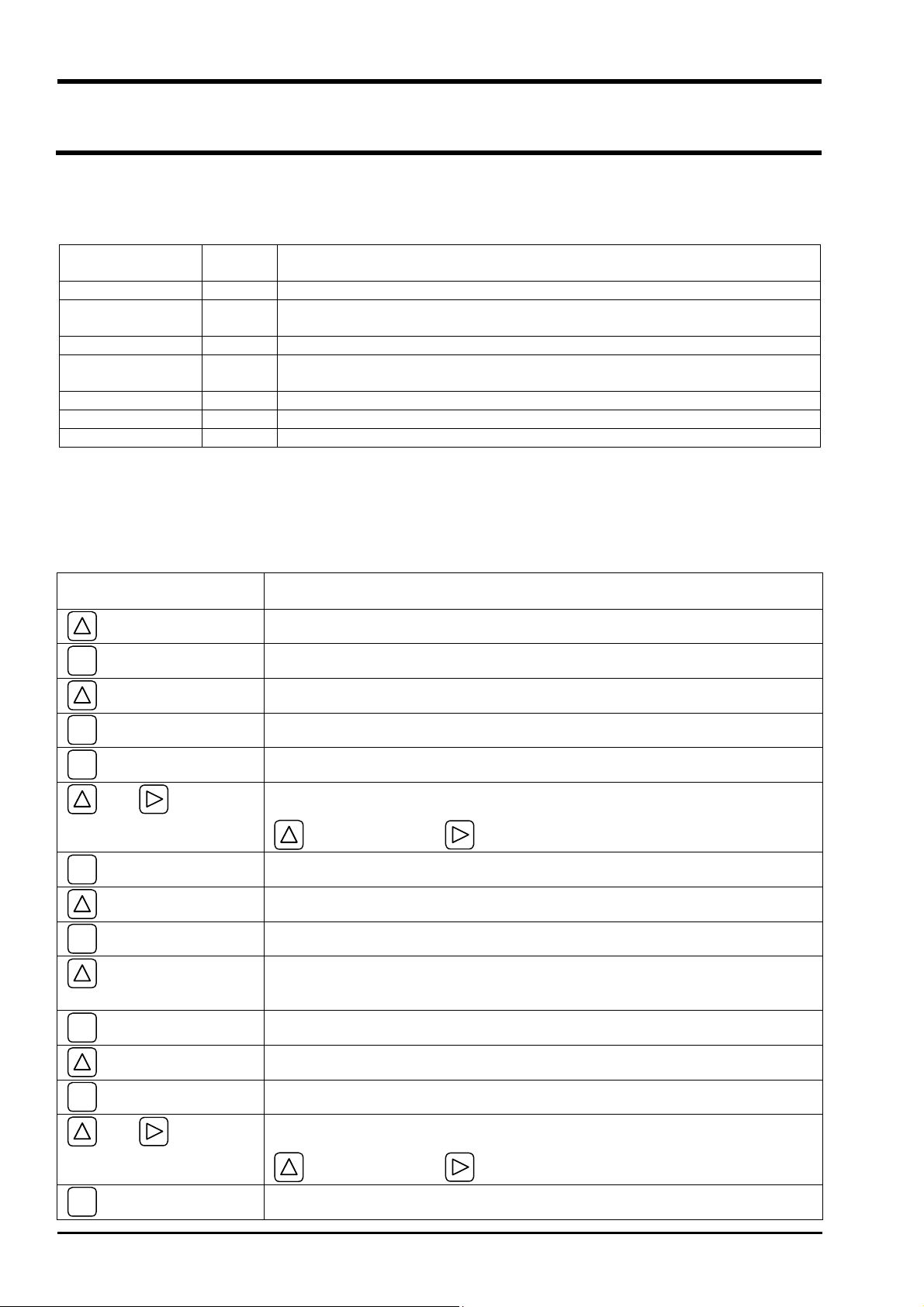
4.2. Configuration of keys
key: key for:
Measurement Mode
Par.
Protection
OUTPUT SETTING
(Section 4.4.1.)
ENT
ESC
key for
Protection ON
Protection OFF
ZERO ADJUST CLEAR
(Section 4.5.1.) SET ZERO
DAMPING (Section 4.5.2.)
CUTOFF (Section 4.5.3.)
DISPLAY
(Section 4.5.4.)
INPUT ID NO
1st.ROW VELOCITY
2nd.ROW VELOCITY
FLOW RATE
FLOW RATE(%)
+TOTAL(ACTUAL)
+TOTAL(PULSE)
-TOTAL(ACTUAL)
-TOTAL(PULSE)
FLOW RATE
FLOW RATE(%)
+TOTAL(ACTUAL)
+TOTAL(PULSE)
-TOTAL(ACTUAL)
-TOTAL(PULSE)
RANGE
FLOW RATE
(Section 4.5.5.)
TOTAL
(Section 4.5.6.)
FLOW SPAN-1
FLOW SPAN-2
HYSTERESIS
BURNOUT
(CURRENT) HOLD
BURNOUT TIMER
TOTAL MODE
PULSE VALUE
PULSE WIDTH
TOTAL PRESET
OVER SCALE
UNDER SCALE
ZERO
START
STOP
RESET
5.0ms
10.0ms
50.0ms
100.0ms
200.0ms
- 28 -
INF-TN1FLRS-E
Page 37

DO1 OUT
(Section 4.5.7.)
DO2 OUT
(Section 4.5.7.)
CALIBRATION SPAN
(Section 4.5.8.)
NOT USED
+TOTAL PULSE
-TOTAL PULSE
FLOW SPAN-2
ALARM
FLOW SWITCH
TOTAL SWITCH
NOT USED
+TOTAL PULSE
-TOTAL PULSE
FLOW SPAN-2
ALARM
FLOW SWITCH
TOTAL SWITCH
BURNOUT(TOTAL)
BURNOUT TIMER
ALL
HARDWARE FAULT
PROCESS ERROR
UPPER SWITCH
LOWER SWITCH
ALL
HARDWARE FAULT
PROCESS ERROR
UPPER SWITCH
LOWER SWITCH
HOLD
COUNT
CONTACT ACTION
CONTACT ACTION
ACTIVE ON
ACTIVE OFF
ACTIVE ON
ACTIVE OFF
MEASURE SETUP
SYSTEM UNIT
(Section 4.6.1.)
FLOW UNIT
(Section 4.6.2.)
TOTAL UNIT
(Section 4.6.3.)
(Section 4.6.4.)
PIPE PARAMETER
(S= )
METRIC
ENGLISH
L/S
L/min
L/h
ML/d
m3/s
etc.
mL
L
m3
km3
Mm3
etc.
OUTER DIAMETER
PIPE MATERIAL
WALL THICKNESS
PVC
PVDF
PEEK
PP
CARBON STEEL
STAINLESS STEEL
COPPER
PIPE S.V
INF-TN1FLRS-E
-29-
Page 38

MAINTENANCE
MODE
LINING MATERIAL
For NO LINING
LINING THICKNESS
KIND OF FLUID
KINEMA TIC VISCO
SENSOR MOUNTING
SENSOR TYPE
CURRENT
CALIBRATION
CURRENT OUPUT SETTING (Section 4.7.2.)
TOTAL PULSE (Section 4.7.3.)
STATUS OUTPUT
(Section 4.7.4.)
TEST MODE
(Section 4.7.5.)
COMMUNICATION
(Section 4.7.6.)
(Section 4.7.1.)
4mA
20mA
ON
OFF
NOT USED
SETTING
COM.MODE
COM.BAUD RATE
COM.PARITY
COM.STOP BIT
COM.SLAVE NO.
NO LINING
TAR EPOXY
MORTAR
RUBBER
TEFLON
PYREXGLASS
LINING S.V
WATER
SEA WATER
FLUID S.V
V
Z
FLS_12
FLS_22
INPUT DATA
TRACKING TIME
RS-232C
RS-485
2400BPS
4800BPS
9600BPS
19200BPS
NON.
ODD
EVEN
1BIT
2BITS
- 30 -
SYNCHRONIZATION
(Section 4.7.7.)
LANGUAGE
(Section 4.7.8.)
REGISTER ID No.
(Section 4.7.9.)
VER. No. (Section 4.7.10.)
SERVICE (for our serviceman only)
MASTER
SLAVE
ENGLISH
JAPANESE
GERMAN
FRENCH
SPANISH
INF-TN1FLRS-E
Page 39

4.3. Initial values of parameters
The following gives factory set values (except when parameter setting is specified).
No. Setting item Settable range Initial value Settable value
1 Parameter protection 2 menus PROTECTION
ON
2 ID No. 0000 to 9999 0000
3 Unit system 2 menus Metric Metric (metric system),
4 Flow rate unit
12 menus
m3/h
(Metric system)
12 menus
(Inch system)
5 Total unit
8 menus
m3
(Metric system)
10 menus
(Inch system)
6 Pipe outer diameter 10.00 to 300mm 60.00mm [mm, in]
7 Pipe material 10 menus
PVC PVC, PVDF, PEEK, PP, CARBON STEEL,
Sound velocity: 1000
to 3700 m/s.
8 Wall thickness 0.1 to 50.00mm 4.50mm [mm, in]
9 Lining material 7 menus
Measurement conditions
Sound velocity: 1000
No lining No lining, tar epoxy, mortar, rubber, Teflon,
to 3700m/s
10 Lining thickness 0.01 to 50.00 - [mm, in]
11 Fluid type 3 menus
Water Water, sea water,
Sound velocity:
500 to 2500m/s
12 Kinematic
viscosity
13 Sensor mounting
0.0001 to 999.9999
×10-6m
2
/s
1.0038×10-
6m2/s
2 menus V V, Z
method
14
Sensor type 2 menus FLS_12 FLS_12, FLS_22
15 Zero adjustment 2 menus Clear
(unadjusted)
16 Damping 0 to 100sec 5sec sec
17 Low flow rate
cutting
18 Display 1st line
contents
19 Display 1st line
0 to 5 m/s in terms of
0.001L/s [The unit selected at No. 4]
flow velocity
7 menus Flow velocity
(m/s)
00000.000
decimal point
position
20 Display 2nd line
7 menus Flow rate (m3/h) Flow velocity, flow rate (ACTUAL),
contents
Output conditions
21
Display 2nd line
00000.000
decimal point
position
PROTECTION ON,
PROTECTION OFF
―――――
English (inch system)
L/s L/min L/h ML/d m3/s m3/min
3
m
/h Mm3/d BBL/s BBL/min
BBL/h MBBL/d
gal/s gal/min gal/h Mgal/d ft
3
ft
/min ft3/h Mft3/d BBL/s BBL/min
BBL/h MBBL/d
mL L m3 km3 Mm3 mBBL BBL
kBBL
gal kgal ft
3
kft3 Mft3 mBBL BBL
kBBL ACRE-in ACRE-ft
STAINLESS STEEL, COPPER,
other (sound velocity: ____ [m/s, ft/s])
Pyrexglass,
other (sound velocity: ____ [m/s, ft/s])
other (Sound velocity: [m/s, ft/s])
2
[×10-6m
/s, ft2/s]
Set zero, clear (factory set at clear)
Flow velocity, flow rate (ACTUAL),
flow rate (%), forward total,
reverse total, forward total pulse,
reverse total pulse
(smear a desired place)
flow rate (%), forward total,
reverse total, forward total pulse,
reverse total pulse
(smear a desired place)
3
/s
INF-TN1FLRS-E
-31-
Page 40

No. Setting item Settable range Initial value Settable value
22 Flow span-1 0.3 to 10 m/s in
terms of flow
velocity
23 Flow span-2 0.3 to 10 m/s in
terms of flow
velocity
24 Hysteresis 0 to 10% 5.00% %
25 Burnout 4 menus Hold Hold, upper limit, lower limit, zero
26
27 Total action 3 menus Start Start, stop, reset
28 Pulse value 0.00001 to 9999999 1m3 [The unit selected at No. 5]
29 Total pulse
30 Burnout 2 menus Hold Hold, count
31
32 DO1 output type ○ 5 output contents
33 DO1 output action 2 menus ––– ON, OFF
34 DO2 output type ○ 5 output contents
35 DO output action 2 menus ––– ON, OFF
36
Analog output
Burnout timer 0 to 100sec 10sec sec
5 menus 5msec 5, 10, 50, 100, 200msec
width
Total output
Burnout timer 0 to 100sec 10sec sec
menus.
○ 3 alarm menus.
○ Flow switch
range 0 to 10 m/s
in terms of flow
Output conditions
Span calibration
velocity.
○ Total switch range
0.000001 to
99999999
menus.
○ 3 alarm menus.
○ Flow switch
range 0 to 10 m/s
in terms of flow
velocity.
○ Total switch range
0.000001 to
99999999
0 to ±200%
10.0000m3/h [The unit selected at No. 4]
0.0000m3/h [The unit selected at No. 4]
NOT USED
NOT USED
100.0% %
NOT USED
Flow direction
Alarm [all, hard, process]
Flow switches
Upper limit
[ [The unit selected at No. 4]]
Lower limit
[ [The unit selected at No. 4]]
Total switch
[ [The unit selected at No. 5]]
Unused
Flow direction
Alarm [all, hard, process]
Flow switches
Upper limit
[ [The unit selected at No. 4]]
Lower limit
[ [The unit selected at No. 4]]
Total switch
[ [The unit selected at No. 5]]
- 32 -
INF-TN1FLRS-E
Page 41

4.4. Parameter protection
4.4.1. Parameter protection ON/OFF
Description
Parameters can be protected so that the flow meter settings will not carelessly be changed.
z
Parameters can be protected by setting the "ID No." (Note) in the maintenance mode.
z
Note: 4 digits are factory set at "0000" (see Section 4.7.9).
Settable range : PROTECTION ON : Parameters cannot be changed.
PROTECTION OFF : Parameters can be changed.
For concrete keying, refer to the following examples.
Typical operation Change the parameter protection from ON to OFF (suppose ID No. is "2234").
Keying order Description Indication
ENT
▼
▼
Pressed in the measurement mode to indicate [PAR.
PROTECTION].
Pressed to blink the 2nd line.
PAR. PROTECTION
PROTECTION ON
PAR. PROTECTION
PROTECTION ON
▼
ENT
▼
▼
▼
ENT
▼
▼
▼
ENT
--- Parameter protection canceled.---
Pressed to indicate "PROTECTION OFF".
Pressed to indicate “INPUT ID NO.”.
Pressed to indicate "0000" and blink the cursor.
Note: If ID No. is "0000" (as factory set), press
key to release the parameter protection.
Pressed until ID No. [2234] is composed.
Pressed.
* If ID No. does not coincide, "INPUT ERROR!"
appears, and the input screen is resumed.
ENT
PAR. PROTECTION
PROTECTION OFF
PAR. PROTECTION
½½ COMPLETE ½½
INPUT ID NO
INPUT ID NO
0000
INPUT ID NO
2234
ID NO INPUT
½½ COMPLETE ½½
PAR. PROTECTION
PROTECTION OFF
½½½½
↓
↓
INF-TN1FLRS-E
-33-
Page 42

4.5. Output setup mode
4.5.1. Adjusting zero point
Description
Zero point is calibrated.
z
Settable range
CLEAR: Clears the zero point calibration value to "0". Used in case the flow cannot be stopped when
calibrating the zero point.
Note: 1. Where possible, stop the flow and carry out "SET ZERO" stated below. Otherwise, an
error may slip in the zero point.
SET ZERO: A point where "SET ZERO" is carried out is regarded as zero. Used for calibrating the zero point
upon stopping the flow.
Note: 2. The flow must completely be stopped. Otherwise, the flowing status is regarded as zero,
thereby causing an error.
For concrete keying, refer to the typical operation indicated below. Set the parameter protection to OFF beforehand
(Section 4.4.1).
Typical operation Completely fill the piping, close the upstream and downstream valves, and proceed to zero point
calibration.
Keying order Description Indication
▼
Pressed twice to indicate "OUTPUT SETUP".
OUTPUT SETUP
ENT
▼
▼
ENT
▼
▼
▼
▼
ESC
Pressed twice to indicate "ZERO ADJUST" and blink the
cursor.
Pressed to select "SET ZERO".
Pressed to execute "SET ZERO".
* Be sure to completely stop the flow beforehand.
--- Zero point calibrated.---
Press
ESC
the measurement mode.
key once, and
key 3 times to resume
ZERO ADJUST
CLEAR
ZERO ADJUST
SET ZERO
ZERO ADJUST
½½ COMPLETE ½½
ZERO ADJUST
SET ZERO
0.000 m/s
0.000 m3/h
↓
- 34 -
INF-TN1FLRS-E
Page 43

4.5.2. Setting the damping
Description
Used for attenuating the variation of measured value.
z
A time constant is set (response time of about 63%).
Settable range: 0 to 100 sec in 1 sec steps.
Note: In case you set to 0 sec, response time become as below.
• System cycle: 0.2 sec
• Dead time: less than 0.2 sec
• Time constant: 0.1 sec
For concrete keying, refer to the typical operation indicated below. Set the parameter protection to OFF beforehand
(Section 4.4.1).
Typical operation Change the damping from 5 to 20 sec.
Keying order Description Indication
▼
Pressed twice to indicate "OUTPUT SETUP".
OUTPUT SETUP
ENT
▼
▼
ENT
▼
▼
ENT
▼
▼
▼
▼
ESC
Pressed to indicate "ZERO ADJUST".
Pressed to indicate "DAMPING".
Pressed to blink the cursor.
Operated to select "20".
Pressed to register it.
--- Damping registered.---
Press
ESC
key once, and key 3 times to resume
the measurement mode.
ZERO ADJUST
SET ZERO
DAMPING
5 sec
DAMPING
005 sec
DAMPING
020 sec
DAMPING
½½ COMPLETE ½½
DAMPING
20 sec
0.000 m/s
0.000 m3/h
↓
INF-TN1FLRS-E
-35-
Page 44

4.5.3. Setting the low flow rate cutting
Description
The output can be cut when the flow rate is too small.
z
Effective for indication, analog output (4-20 mA) and total
z
Output
operation.
Settable range: 0 to 5 [m/s] in terms of flow velocity (factory set
at 0.001 [L/s]).
Notes
1. As required, set the low flow rate cut because the flow meter
may read a flow rate when the fluid in the piping is moving
on account of convection, etc. even if the valves are closed.
2. The flow rate unit is as selected by "FLOW UNIT" in
"MEASURE SETUP" (see Section 4.6.2).
Low flow rate cut setting value
Flow rate
For concrete keying, refer to the typical operation indicated below. Set the parameter protection to OFF beforehand
(Section 4.4.1).
Typical operation Set the low flow rate cut point to 0.5 [m
3
/h].
Keying order Description Indication
ENT
▼
▼
Pressed twice to indicate "OUTPUT SETUP".
Pressed to indicate "ZERO ADJUST".
OUTPUT SETUP
ZERO ADJUST
SET ZERO
Pressed twice to indicate "CUTOFF".
▼
ENT
Pressed to blink the cursor.
▼
Operated to compose "0.5".
▼
ENT
Pressed to register it.
CUTOFF
0.0010 m3/h
CUTOFF
0000.0010 m3/h
CUTOFF
0000.5000 m3/h
CUTOFF
½½ COMPLETE ½½
▼
↓
▼
ESC
▼
▼
Press
--- CUTOFF registered.---
ESC
key once, and
the measurement mode.
key 3 times to resume
CUTOFF
0.500 m3/h
0.000 m/s
0.000 m3/h
- 36 -
INF-TN1FLRS-E
Page 45

4.5.4. Setting the LCD indication
Description
Flow velocity indication
z
Selectable flow velocity units : m/s (if SYSTEM UNIT was set to METRIC)
: ft/s (if SYSTEM UNIT was set to ENGLISH) (Section 4.6.1).
Note: 1. The decimal point position is fixed.
Flow rate indication
z
Selectable flow rate indications: Actual value reading, % reading.
Note: 2. The indication unit is as selected by FLOW UNIT (Section 4.6.2).
Total indication
z
Selectable total indications: Actual total value reading (forward/reverse flow), total pulse count (forward/reverse
flow).
Note: 3. When total unit is changed, perform “RESET”. (Refer to item 4.5.6)
Conversion of total memory contents due to unit change is not carried out.
How to validate the indication
z
Set the DISPLAY setting mode to 1st. ROW (for indication on 1st line) or 2nd. ROW (for indication on 2nd line),
and further select indication contents.
For concrete keying, refer to the typical operation indicated below. Set the parameter protection to OFF beforehand
(Section 4.4.1).
Typical operation Set the LCD indication on 1st line to % reading.
Keying order Description Indication
▼
Pressed twice to indicate "OUTPUT SETUP".
OUTPUT SETUP
ENT
▼
▼
ENT
▼
ENT
▼
▼
ENT
▼
▼
ENT
▼
▼
▼
▼
ESC
Pressed to indicate "ZERO ADJUST".
Pressed 3 times to indicate "DISPLAY".
Pressed to blink the cursor.
Pressed again to select "1st. ROW".
Pressed twice to select "FLOW RATE (%)".
Pressed to enter "FLOW RATE (%)" and indicate "1st.
ROW DIGIT".
Pressed to shift the decimal point position to next place.
Pressed to register it.
--- FLOW RATE (%) indication validated.---
Press
ESC
key 2 times, and key 3 times to
resume the measurement mode
ZERO ADJUST
CLEAR
DISPLAY
1ST. ROW
DISPLAY
1ST. ROW
1ST. ROW
VELOCITY
1ST. ROW
FLOW RATE (%)
1ST. ROW DIGIT
½½½½. ½½
1ST. ROW DIGIT
½½½½½. ½
1ST. ROW DIGIT
½½ COMPLETE ½½
1ST. ROW
FLOW RATE (%)
0.0 %
0.000 m3/h
↓
INF-TN1FLRS-E
-37-
Page 46

4.5.5. Setting the flow rate and flow velocity range
4.5.5.1. Setting the flow rate range (single range FLO W SPAN-1)
Description
The range (full scale) of flow rate to measure is set.
z
* The analog output (4-20 mA) corresponds to the range setting.
After changing the range, adjust zero point (see Section 4.5.1.).
z
Settable range: 0.3 to 10 [m/s] in terms of flow velocity in piping.
z
20mA
SPAN-1
* Piping parameters and FLOW UNIT must be set beforehand.
* If a value beyond the settable range is inputted, "INPUT ERROR"
appears and then last setting is resumed.
* If "piping parameters" or "FLOW UNIT" has been changed after setting
the range, recommence the range setting.
4mA
0 100%
Flow rate
Note: 1. The flow rate unit is as selected by "FLOW UNIT" in the "MEASURE SETUP" mode (see Section 4.6.2.).
For concrete keying, refer to the typical operation indicated below. Set the parameter protection to OFF beforehand
(Section 4.4.1).
Typical operation Set the "FLOW SPAN-1" to 60 m
3
/h.
* Set the piping parameters and "FLOW UNIT" beforehand.
Keying order Description Indication
▼
ENT
▼
Pressed twice to indicate "OUTPUT SETUP".
Pressed to select the ZERO ADJUST mode.
OUTPUT SETUP
ZERO ADJUST
CLEAR
▼
ENT
▼
ENT
▼
ENT
▼
▼
▼
Pressed 4 times to indicate "RANGE".
Pressed to blink the cursor.
Pressed to indicate "FLOW SPAN-1".
Pressed to blink the cursor.
Pressed repeatedly until the cursor is positioned at "1".
Pressed 5 times to select "6".
Note: To change the decimal point position, align the
cursor with a place to change to and operate
RANGE
FLOW RATE
RANGE
FLOW RATE
FLOW SPAN-1
0000010.0 m3/h
FLOW SPAN-1
0000010.0 m3/h
FLOW SPAN-1
0000010.0 m3/h
FLOW SPAN-1
0000060.0 m3/h
key likewise.
ENT
▼
Pressed to register it.
FLOW SPAN-1
½½ COMPLETE ½½
↓
▼
ESC
▼
▼
Press
--- SPAN-1 registered.---
ESC
key 3 times and press key 3 times to
resume the measurement mode.
FLOW SPAN-1
60.0 m3/h
0.000 m/s
0.000 m3/h
- 38 -
INF-TN1FLRS-E
Page 47

4.5.5.2. Setting forwar d automatic 2 ranges
Description
The function carries out a measurement while changing over
z
the range according to the flow rate.
The current output changes with the action range as
z
illustrated on the right.
The hysteresis can be set to between 0 and 10% of the
z
smaller range.
Upon setting DO1 or DO2 to "FLOW SPAN-2", a contact
z
outputs "SPAN-2" action. Select [ACTIVE ON] or
[ACTIVE OFF] separately
(see Section 4.5.7.3.).
After changing the range value, adjust zero point
z
(see Section 4.5.1.).
Settable range: 0.3 to 10 [m/s] in terms of flow velocity in piping for any of SPAN-1 and SPAN-2.
z
* The piping parameters
and FLOW UNIT must be set beforehand.
* If a value beyond the settable range is inputted, "INPUT ERROR" appears and then last setting is resumed.
* If "FLOW UNIT" has been changed after setting the range, recommence the range setting.
* When FLOW SPAN-2 is not used (in the case of single range), set “0” to FLOW SPAN-2.
Note: 1. The flow rate unit is as selected by "FLOW UNIT". Before range setting, set the "FLOW UNIT"
(see Section 4.6.2.).
For concrete keying, refer to the typical operation indicated below. Set the parameter protection to OFF beforehand
(Section 4.4.1).
Typical operation Set "FLOW SPAN-1" to 10 [m
3
/h], "FLOW SPAN-2" to 60 [m3/h], and "HYSTERESIS" to 7%.
* Set the piping parameters and "FLOW UNIT" beforehand.
Keying order Description Indication
Pressed twice to indicate "OUTPUT SETUP".
▼
20mA
4mA
SPAN-1
OUTPUT SETUP
SPAN-2
Hysteresis
ENT
ENT
ENT
ENT
▼
▼
▼
▼
▼
▼
▼
Pressed to indicate "ZERO ADJUST".
Pressed 4 times to indicate "RANGE".
Pressed to blink the cursor.
Pressed to indicate "FLOW SPAN-1".
Pressed to blink the cursor on 2nd line.
Pressed repeatedly until the cursor is positioned at "2".
Pressed repeatedly until "1" appears.
Note: To change the decimal point position, align the
cursor with a place to change to, and press
ZERO ADJUST
CLEAR
RANGE
FLOW RATE
RANGE
FLOW RATE
FLOW SPAN-1
20.0000 m3/h
FLOW SPAN-1
0020.0000 m3/h
FLOW SPAN-1
0020.0000 m3/h
FLOW SPAN-1
0010.0000 m3/h
key likewise.
ENT
▼
INF-TN1FLRS-E
Pressed to register it.
FLOW SPAN-1
½½ COMPLETE ½½
↓
-39-
Page 48

ENT
ENT
▼
▼
▼
▼
▼
▼
▼
▼
▼
▼
▼
▼
--- FLOW SPAN-1 registered.---
Pressed to indicate "FLOW SPAN-2".
Pressed to blink the cursor.
Pressed twice to move the cursor.
Pressed 6 times to select "6".
Pressed to register it.
FLOW SPAN-1
10.0000 m3/h
FLOW SAPN-2
0.0000 m3/h
FLOW SAPN-2
0000.0000 m3/h
FLOW SPAN-2
0000.0000 m3/h
FLOW SPAN-2
0060.0000 m3/h
FLOW SPAN-2
½½ COMPLETE ½½
↓
--- FLOW SPAN-2 registered.---
Pressed to indicate "HYSTERESIS".
FLOW SPAN-2
60.0000 m3/h
HYSTERESIS
5.00 %
ENT
ENT
▼
▼
▼
▼
Pressed to blink the cursor.
Pressed to move the cursor.
Pressed twice to select "7".
Pressed to register it.
HYSTERESIS
05.00 %
HYSTERESIS
05.00 %
HYSTERRSIS
07.00 %
HYSTERESIS
½½ COMPLETE ½½
↓
▼
ESC
▼
▼
Press
--- HYSTERESIS registered.---
ESC
key 3 times, and press key 3 times to
resume the measurement mode.
HYSTERESIS
7.00 %
0.000 m/s
0.000 m3/h
- 40 -
INF-TN1FLRS-E
Page 49

4.5.5.3. Setting forwar d/reverse automatic 2 ranges
Description
The function measures the flow rate of either forward or reverse
z
20mA
flow while changing over the range corresponding to the flow
direction.
The current output changes with the action range as illustrated on
z
the right.
The hysteresis can be set to between 0 and 10% of the action
z
4mA
range.
Upon setting DO1 or DO2 to "FLOW SPAN-2", a contact outputs
z
"SPAN-2" action. Select [ACTIVE ON] or [ACTIVE OFF]
separately (see Section 4.5.7.3.).
After changing the range value, adjust zero point (see Section 4.5.1.).
z
Settable range: ±0.3 to 10 [m/s] in terms of flow velocity in piping for any of SPAN-1 and SPAN-2.
z
* The piping parameters
and FLOW UNIT must be set beforehand.
Hysteresis
* If a value beyond the settable range is inputted, "INPUT ERROR" appears and then last setting is resumed.
* If "FLOW UNIT" has been changed after setting the range, recommence the range setting.
Note: 1. The flow rate unit is as selected by "FLOW UNIT". Before range setting, set the "FLOW UNIT"
(see
Section 4.6.2.).
For concrete keying, refer to the typical operation indicated below. Set the parameter protection to OFF beforehand
(Section 4.4.1).
Typical operation Set "FLOW SPAN-1" to 20 [m
3
/h], "FLOW SPAN-2" to -10 [m3/h], and "HYSTERESIS" to 7%.
* Set the piping parameters and "FLOW UNIT" beforehand.
Keying order Description Indication
Pressed twice to indicate "OUTPUT SETUP".
▼
OUTPUT SETUP
ENT
ENT
ENT
ENT
▼
▼
▼
▼
▼
▼
▼
Pressed to indicate "ZERO ADJUST".
Pressed 4 times to indicate "RANGE".
Pressed to blink the cursor.
Pressed to indicate "FLOW SPAN-1".
Pressed to blink the cursor.
Pressed repeatedly until the cursor is positioned at "5".
Pressed repeatedly until "2" appears.
Note: To change the decimal point position, align the
cursor with a place to change to, and press
ZERO ADJUST
CLEAR
RANGE
FLOW RATE
RANGE
FLOW RATE
FLOW SPAN-1
50.0000 m3/h
FLOW SPAN-1
0050.0000 m3/h
FLOW SPAN-1
0050.0000 m3/h
FLOW SPAN-1
0020.0000 m3/h
key likewise
ENT
▼
INF-TN1FLRS-E
Pressed to register it.
FLOW SPAN-1
½½ COMPLETE ½½
↓
-41-
Page 50

ENT
ENT
▼
▼
▼
▼
▼
▼
▼
▼
▼
▼
▼
▼
▼
--- FLOW SPAN-1 registered.---
Pressed to indicate "FLOW SPAN-2".
Pressed to blink the cursor.
Pressed repeatedly until "-" appears on 1st place.
Pressed twice to move the cursor.
Pressed to select "1".
Pressed to register it.
FLOW SPAN-1
20.0000 m3/h
FLOW SAPN-2
0.0000 m3/h
FLOW SAPN-2
0000.0000 m3/h
FLOW SPAN-2
–000.0000 m3/h
FLOW SPAN-2
–000.0000 m3/h
FLOW SPAN-2
–010.0000 m3/h
FLOW SPAN-2
½½ COMPLETE ½½
↓
--- FLOW SPAN-2 registered.---
Pressed to indicate "HYSTERESIS".
FLOW SPAN-2
–10.0000 m3/h
HYSTERESIS
5.00 %
ENT
ENT
▼
▼
▼
▼
Pressed to blink the cursor.
Pressed to move the cursor.
Pressed twice to select "7".
Pressed to register it.
HYSTERESIS
05.00 %
HYSTERESIS
05.00 %
HYSTERRSIS
07.00 %
HYSTERESIS
½½ COMPLETE ½½
↓
▼
ESC
▼
▼
Press
--- HYSTERESIS registered.---
ESC
key 3 times, and press key 3 times to
resume the measurement mode.
HYSTERESIS
7.00 %
0.000 m/s
0.000 m3/h
- 42 -
INF-TN1FLRS-E
Page 51

4.5.5.4. How to set analog output at error (BURNOUT)
Description
Determine how to set the analog output when received wave error, etc. due to device error, accidental drain of
z
piping or ingress of bubbles.
Settable ranges
z
(1) Analog output (4-20 mA) at error
HOLD (factory set): Outputs a current intensity preceding the error.
OVER SCALE: Outputs 23.2 mA.
UNDER SCALE: Outputs 0.8 mA.
ZERO: Outputs 4 mA.
(2) BURNOUT TIMER (time from error detection to BURNOUT processing) 0 to 100 seconds (factory set at 10
sec).
For concrete keying, refer to the typical operation indicated below. Set the parameter protection to OFF beforehand
(Section 4.4.1).
Typical operation Set the BURNOUT to "OVER SCALE".
Set the BURNOUT TIMER to "20 sec".
* Set the piping parameters and "FLOW UNIT" beforehand.
Keying order Description Indication
▼
Pressed twice to indicate "OUTPUT SETUP".
OUTPUT SETUP
ENT
ENT
ENT
ENT
ENT
▼
▼
▼
▼
▼
▼
▼
▼
▼
▼
▼
▼
Pressed to indicate "ZERO ADJUST".
Pressed 4 times to indicate "RANGE".
Pressed to blink the cursor.
Pressed to indicate "FLOW SPAN-1".
Pressed 3 times to indicate the BURNOUT (CURRENT).
Pressed to blink the 2nd line.
Pressed to indicate "OVER SCALE".
Pressed to register it.
--- “OVER SCALE” registered.---
Pressed to indicate "BURNOUT TIMER".
ZERO ADJUST
CLEAR
RANGE
FLOW RATE
RANGE
FLOW RATE
FLOW SPAN-1
20.0000 m3/h
BURNOUT (CURRENT)
HOLD
BURNOUT (CURRENT)
HOLD
BURNOUT (CURRENT)
OVER SCALE
BURNOUT (CURRENT)
½½ COMPLETE ½½
BURNOUT (CURRENT)
OVER SCALE
BURNOUT TIMER
10 s
↓
ENT
▼
INF-TN1FLRS-E
Pressed to blink the cursor.
BURNOUT TIMER
010 s
-43-
Page 52

▼
▼
ENT
▼
▼
▼
▼
ESC
Pressed to align the cursor with "1".
Pressed to select "2".
Pressed to register it.
--- “BURNOUT TIMER” registered.---
Press
ESC
key 3 times and press key 3 times to
resume the measurement mode.
BURNOUT TIMER
010 s
BURNOUT TIMER
020 s
BURNOUT TIMER
½½ COMPLETE ½½
BURNOUT TIMER
20 s
0.000 m/s
0.000 m3/h
↓
- 44 -
INF-TN1FLRS-E
Page 53

4.5.6. Setting the total
4.5.6.1. Setting the total pulse (pulse value, pulse width)
Description
Set for total a process variable (flow rate) by total meter, etc. according to total pulse output.
z
Pulse value: Total amount (volume) per pulse.
z
A pulse is outputted when the total volume has attained an amount set by the pulse value, and adds to the total pulse
count (in case of total pulse indication).
Settable range: 0.000001 to 99999999.
* Set the total unit before setting the pulse value (see Section 4.6.3.).
Pulse width: Width of total pulse output.
z
Select a pulse width according to a corresponding total meter out of menus.
Settable range: 5 ms, 10 ms, 50 ms, 100 ms, 200 ms.
Note: If the output is through DO2 (relay contact), select 50 ms or longer (see Section 4.5.7.).
Restrictions in the setup
z
Output of total pulses involves the following restrictions depending on the DO output port (DO1, DO2).
DO output port
DO1: Transistor open collector
DO2: Relay contact 1 pulse per day to 1 pulse per second 50ms, 100ms, 200ms
Furthermore, the maximum output frequency is restricted also by the setup of the pulse width.
Therefore, set the pulse width and pulse value so that both of condition 1 and condition 2 indicated below are
satisfied.
Correct motions may not occur, if any setup that does not satisfy both of condition 1 and condition 2 is made.
Condition 1:
1 FLOW SPAN-1
86400
[Hz]
PULSE VALUE [m
Condition 2:
FLOW SPAN-1
PULSE VALUE [m
Note 1) [m3
3
]
Note 1: The range of FLOW SPAN-1 or FLOW SPAN-2, whichever is larger, is the object in the case of 2-range setup.
Note 2: Restrictions in the maximum output frequency of each output port is also applied when the flow rate exceeds
the set range. Therefore, if such a setup that the maximum frequency occurs at the time of 100% flow rate of
the set range is made, there is a possibility where the total pulse output is incapable of following when the flow
rate exceeds 100% and accurate total value cannot be obtained if over-range continues for a long time. If
there are cases where the flow rate exceeds 100%, therefore, review the range and pulse value so that the
maximum frequency will not exceed the restricted level.
Pulse output frequency range
(at the time of full scale flow rate)
1 pulse per day to 100 pulses per
second
Note 1) [m3
/s] 100 [Hz] (case of DO1)
3
] 1 [Hz] (case of DO2)
/s] 1000
2 × PULSE WIDTH [ms]
Pulse width
5ms, 10ms, 50ms, 100ms, 200ms
INF-TN1FLRS-E
-45-
Page 54

Typical calculation
Calculate the range that permits setup of the pulse value under the range (FLOW SPAN-1) and pulse width indicated
below.
When set values of the range (FLOW SPAN-1) and pulse width are as follows;
FLOW SPAN-1: 36 [m
3
/h] (=0.01 [m3/s]), PULSE WIDTH: 50 [ms]
i) Case of DO1 output
From condition 1,
[m3
/s] 0.01 [m3/s]
=
100 [Hz]
= 0.0001 [m3] = 0.1[L]
PULSE VALUE
FLOW SPAN-1
100 [Hz]
PULSE VALUE
FLOW SPAN-1[m3/s] × 86400 [s] = 0.01 [m3/s] × 86400 [s] = 864 [m3]
From the above:
0.1 [L]
PULSE VALUE 864 [m3] ····················· A
From condition 2,
PULSE VALUE
FLOW SPAN-1
= 0.001 [m
[m3
3
] = 1 [L]·········································· B
2 × PULSE WIDTH [ms] 2 × 50 [ms]
/s]
×
1000
= 0.01 [m
3
/s] ×
1000
The settable range of the pulse value that satisfies both of condition 1 and condition 2 is as follows from results
of calculation A and B:
1 [L]
PULSE VALUE 864 [m3]
ii) Case of DO2 output
From condition 1,
PULSE VALUE
FLOW SPAN-1
1 [Hz]
[m3
/s] 0.01 [m3/s]
=
1 [Hz]
= 0.01 [m3] = 10 [L] ······················C
Condition 2 is same as that of the case of DO1 output indicated above.
Therefore, the settable range of the pulse value is as follows from results of calculation B and C:
10 [L]
PULSE VALUE 864 [m3]
For concrete keying, refer to the typical operation indicated in the next page. Set the parameter protection to OFF
beforehand (Section 4.4.1).
- 46 -
INF-TN1FLRS-E
Page 55

Typical operation Set the pulse value to 0.1 m
3
/pulse, and the pulse width to 50 ms.
* Set the total unit beforehand.
Keying order Description Indication
Pressed twice to indicate "OUTPUT SETUP".
▼
OUTPUT SETUP
ENT
ENT
ENT
ENT
▼
▼
▼
▼
▼
▼
▼
▼
Pressed to indicate "ZERO ADJUST".
Pressed 4 times to indicate "RANGE".
Pressed to blink the cursor.
Pressed to indicate "TOTAL" on 2nd line.
Pressed to indicate "TOTAL MODE".
Pressed to indicate "PULSE VALUE".
Pressed to indicate the cursor.
Pressed 7 times to move the cursor.
ZERO ADJUST
CLEAR
RANGE
FLOW RATE
RANGE
FLOW RATE
RANGE
TOT AL
TOTAL MODE
START
PULSE VALUE
1 m3
PULSE VALUE
000000001 m3
PULSE VALUE
000000001 m3
ESC
▼
ENT
▼
▼
▼
▼
▼
ENT
▼
▼
ENT
▼
▼
▼
▼
Press
Pressed 9 times to indicate the decimal point.
Pressed to register.
--- “PULSE VALUE” registered.---
Pressed to indicate the PULSE WIDTH.
Pressed to blink the cursor.
Pressed twice to select "50.0 msec".
Pressed to register it.
--- “PULSE WIDTH” registered.---
ESC
key 3 times, and key 3 times to
resume the measurement mode.
PULSE VALUE
0000000.1 m3
PULSE VALUE
½½ COMPLETE ½½
↓
PULSE VALUE
0.1 m3
PULSE WIDTH
5.0 msec
PULSE WIDTH
5.0 msec
PULSE WIDTH
50.0 msec
PULSE WIDTH
½½ COMPLETE ½½
↓
PULSE WIDTH
50.0 msec
0.000 m/s
0.000 m3/h
INF-TN1FLRS-E
-47-
Page 56

4.5.6.2. Setting the preset value
Description
Preset value: Value which appears on the total counter when the total value has been reset.
z
Settable range: 0 to 99999999
Notes
1. A resetting action simultaneously resets both forward total memory and reverse total memory.
2. Set the total unit beforehand in the MEASURE SETUP mode (see Section 4.6.3.).
Total value
Reset
Reset
Reset
Preset value
Time
For concrete keying, refer to the typical operation indicated below. Set the parameter protection to OFF beforehand
(Section 4.4.1)
Typical operation Set the preset value to 100 m
3
.
* Set the total unit beforehand.
Keying order Description Indication
ESC
▼
ENT
▼
▼
ENT
▼
▼
ENT
▼
▼
ENT
▼
▼
▼
ENT
▼
▼
▼
▼
Press
Pressed twice to indicate "OUTPUT SETUP".
Pressed to indicate "ZERO ADJUST".
Pressed 4 times to indicate "RANGE".
Pressed to blink the cursor.
Pressed to indicate "TOTAL" on 2nd line.
Pressed to indicate "TOTAL MODE".
Pressed 3 times to indicate "TOTAL PRESET".
Pressed to indicate the cursor.
Pressed 6 times to move the cursor.
* Note that input cannot be entered on the firsr digit (the
leftmost digit).
Pressed to select "1".
Pressed to register it.
--- PRESET value registered.---
ESC
key 3 times, and key 3 times to
resume the measurement mode.
OUTPUT SETUP
ZERO ADJUST
CLEAR
RANGE
FLOW RATE
RANGE
FLOW RATE
RANGE
TOT AL
TOTAL MODE
START
TOTAL PRESET
0 m3
TOTAL PRESET
000000000 m3
TOTAL PRESET
000000000 m3
TOTAL PRESET
000000100 m3
TOTAL PRESET
½½ COMPLETE ½½
TOTAL PRESET
100 m3
0.000 m/s
0.000 m3/h
↓
- 48 -
INF-TN1FLRS-E
Page 57

4.5.6.3. TOTAL mode (total reset, start, stop)
Description
The total is started, stopped or reset.
z
Settable range: START, STOP, RESET.
z
START: Carried out the total.
STOP: Stops the total.
RESET: Reset the total memory to the preset value.
Notes
1. A resetting action simultaneously resets both forward total memory and reverse total memory.
2. To start a total after resetting a total value, be sure to set the "START"
For concrete keying, refer to the typical operation indicated below. Set the parameter protection to OFF beforehand
(Section 4.4.1).
Typical operation Reset the total value (preset value 0 m
3
), and restart a total.
Keying order Description Indication
Pressed twice to indicate "OUTPUT SETUP".
▼
.
0.00 m3/h
+ 127.26 m3
OUTPUT SETUP
ENT
ENT
ENT
ENT
ENT
ENT
▼
▼
▼
▼
▼
▼
▼
▼
▼
▼
▼
▼
Pressed to indicate "ZERO ADJUST".
Pressed 4 times to indicate "RANGE".
Pressed to blink the cursor.
Pressed to indicate "TOTAL" on 2nd line.
Pressed to indicate "TOTAL MODE".
Pressed to blink the cursor.
Pressed twice to indicate "RESET".
Pressed to execute "RESET".
Note: After resetting,
. To resume a total, execute "START".
stops
the total operation automatically
--- RESET has ended.---
Pressed to blink the cursor.
ZERO ADJUST
CLEAR
RANGE
FLOW RATE
RANGE
FLOW RATE
RANGE
TOT AL
TOTAL MODE
START
TOTAL MODE
START
TOTAL MODE
RESET
TOTAL MODE
½½ COMPLETE ½½
TOTAL MODE
STOP
TOTAL MODE
STOP
↓
▼
INF-TN1FLRS-E
Pressed twice to indicate "START".
TOTAL MODE
START
-49-
Page 58

ENT
▼
Pressed to start a total operation.
TOTAL MODE
½½ COMPLETE ½½
↓
▼
ESC
▼
▼
Press
--- Total operation has started.---
ESC
key 3 times, and key 3 times to
resume the measurement mode.
TOTAL MODE
START
0.00 m3/h
+ 0.00 m3
4.5.6.4. Determining how to dispose of total at err or (BURNOUT)
Description
BURNOUT(TOTAL)
Determines how to dispose of the total when the measurement status is abnormal on account of an empty pipe
z
interior or bubbles mixed in fluid (common to total indication and total pulse output).
Settable range
z
HOLD: Stops the total (as factory set).
COUNT: Continues the total according to a flow rate marked immediately before the error occurrence.
BURNOUT TIMER
Sets the time from error occurrence to error processing.
z
Settable range: 0 to 100 sec (factory set at 10 sec).
z
The total continues until the burnout timer is actuated.
For concrete keying, refer to the typical operation indicated below. Set the parameter protection to OFF beforehand
(Section 4.4.1).
Typical operation Change the processing from "COUNT" to "HOLD", and change the burnout timer setting from 10
seconds to 15 seconds.
Keying order Description Indication
Pressed twice to indicate "OUTPUT SETUP".
▼
OUTPUT SETUP
ENT
ENT
ENT
ENT
▼
▼
▼
▼
▼
▼
▼
Pressed to indicate "ZERO ADJUST".
Pressed 4 times to indicate "RANGE".
Pressed to blink the cursor.
Pressed to indicate "TOTAL"" on 2nd line.
Pressed to indicate "TOTAL MODE".
Pressed 4 times to indicate "BURNOUT (TOTAL)".
Pressed to blink the cursor.
ZERO ADJUST
CLEAR
RANGE
FLOW RATE
RANGE
FLOW RATE
RANGE
TOT AL
TOTAL MODE
START
BURNOUT (TOTAL)
COUNT
BURNOUT (TOTAL)
COUNT
- 50 -
INF-TN1FLRS-E
Page 59

Pressed to indicate "HOLD".
▼
BURNOUT (TOTAL)
HOLD
ENT
▼
Pressed to register "HOLD".
BURNOUT (TOTAL)
½½ COMPLETE ½½
↓
▼
ENT
ENT
▼
▼
▼
▼
▼
▼
▼
--- "HOLD" registered.---
Pressed to indicate "BURNOUT TIMER".
Pressed to blink the cursor.
Pressed twice to move the cursor.
Pressed 5 times to select "5".
Pressed to register it.
BURNOUT (TOTAL)
HOLD
BURNOUT TIMER
10 s
BURNOUT TIMER
010 s
BURNOUT TIMER
010 s
BURNOUT TIMER
015 s
BURNOUT TIMER
½½ COMPLETE ½½
↓
▼
ESC
▼
▼
Press
--- “BURNOUT TIMER” registered.---
ESC
key 3 times, and key 3 times to
resume the measurement mode.
BURNOUT TIMER
015 s
0.00 m3/h
+ 0.00 m3
INF-TN1FLRS-E
-51-
Page 60

4.5.7. Setting the DO output
Description
Selects the output of total pulses and statuses (of alarm, flow switch, total switch, etc.).
Settable ranges (common to DO1 and DO2)
NOT USED : Do not use the contact output.
+TOTAL PULSE : Output the forward total pulses.
–TOTAL PULSE : Output the reverse total pulses.
FLOW SPAN-2 : Select a contact output at SPAN-2 measurement status (forward automatic 2 ranges,
forward/reverse automatic 2 ranges).
ALARM
HARDWARE : Select a contact output at EEPROM error.
PROCESS : Select a contact output when wave is not received or is unstable.
FLOW SWITCH
UPPER SWITCH : Select a contact output when flow rate is above the setting.
LOWER SWITCH : Select a contact output when flow rate is below the setting.
TOTAL SWITCH : Select a contact output when total value exceeds the setting.
CONTACT ACTION
ACTIVE ON : Normally OFF (DO1) or normally open (DO2).
ACTIVE OFF : Normally ON (DO1) or normally closed (DO2).
Note: DO output specifications
DO1 : Open collector, contact capacity 30 V DC, 0.1 A.
When total pulse output is selected (See 4.5.6.1)
1 pulse/day to 100 pulses/s (at full scale flow rate).
Pulse width: 5, 10, 50, 100 or 200 ms.
DO2 : Relay contact, contact capacity 220 V AC/30 V DC, 1 A.
Life ... 200,000 operations (under rated load), replaceable with socket.
When total pulse output is selected (See 4.5.6.1)
1 pulse/day to 1 pulse/s (at full scale flow rate).
Pulse width: 50, 100 or 200 ms.
For concrete keying, refer to the typical operation indicated below. Set the parameter protection to OFF beforehand
(Section 4.4.1).
- 52 -
INF-TN1FLRS-E
Page 61

4.5.7.1. Invalidating the DO output
Description
Invalidates the DO1 OUT and/or DO2 OUT contact output.
z
For concrete keying, refer to the typical operation indicated below. Set the parameter protection to OFF beforehand
(Section 4.4.1).
Typical operation Change the setting of DO1 from "+TOTAL PULSE" to "NOT USED".
Keying order Description Indication
▼
Pressed twice to select the OUTPUT SETUP mode.
OUTPUT SETUP
ENT
▼
▼
ENT
▼
▼
ENT
▼
▼
▼
▼
ESC
Pressed to indicate ZERO ADJUST.
Pressed 5 times to indicate "DO1 OUT".
* Pressing
Pressed to blink the cursor.
Pressed 6 times to indicate "NOT USED" on 2nd line.
Pressed to register "NOT USED".
Press
ESC
the measurement mode.
key again will select "DO2".
--- "NOT USED" registered.---
key once, and key 3 times to resume
ZERO ADJUST
CLEAR
DO1 OUT
+TOTAL PULSE
DO1 OUT
+TOTAL PULSE
DO1 OUT
NOT USED
DO1 OUT
½½ COMPLETE ½½
DO1 OUT
NOT USED
0.000 m/s
0.000 m3/h
↓
INF-TN1FLRS-E
-53-
Page 62

4.5.7.2. How to validate the total pulse output
Description
Validates the total pulse output for DO1 OUT and/or DO2 OUT.
z
+TOTAL PULSE: Forward flow rate total pulse output.
–TOTAL PULSE: Reverse flow rate total pulse output.
Note: Referring to Section 4.5.6.1., set the pulse value, pulse width, etc.
For concrete keying, refer to the typical operation indicated below. Set the parameter protection to OFF beforehand
(Section 4.4.1).
Typical operation Set the DO1 output to "+TOTAL PULSE", and the contact to Normally OFF.
Keying order Description Indication
Pressed twice to select the OUTPUT SETUP mode.
▼
OUTPUT SETUP
ENT
▼
▼
ENT
▼
▼
ENT
▼
Pressed to indicate ZERO ADJUST.
Pressed 5 times to indicate "DO1 OUT".
* Pressing
key again will select "DO2".
Pressed to blink the cursor.
Pressed to indicate "+TOTAL PULSE" on 2nd line. Or,
to select "-TOTAL PULSE", press key again.
Pressed to register "+TOTAL PULSE".
ZERO ADJUST
CLEAR
DO1 OUT
NOT USED
DO1 OUT
NOT USED
DO1 OUT
+TOTAL PULSE
DO1 OUT
½½ COMPLETE ½½
↓
▼
ESC
ENT
ENT
▼
▼
▼
▼
▼
▼
▼
Press
--- “+TOTAL PULSE” registered.---
Pressed to indicate "CONTACT ACTION".
Pressed to register "ACTIVE ON" (normally OFF).
* If it is desired to select Normally ON, press
key.
--- "ACTIVE ON" registered.---
ESC
key twice, and
key 3 times to resume
the measurement mode.
STATUS OUT
CONTACT ACTION
CONTACT ACTION
ACTIVE ON
CONTACT ACTION
½½ COMPLETE ½½
STATUS OUT
CONTACT ACTION
0.000 m/s
0.000 m3/h
↓
- 54 -
INF-TN1FLRS-E
Page 63

4.5.7.3. How to validate out putting the FLOW SPAN-2
Description
Select a contact output as DO1 and/or DO2 at FLOW SPAN-2 measurement status.
z
For concrete keying, refer to the typical operation indicated below. Set the parameter protection to OFF beforehand
(Section 4.4.1).
Typical operation Set the DO1 output to "FLOW SPAN-2". Also set the contact to Normally OFF.
Keying order Description Indication
Pressed twice to select the OUTPUT SETUP mode.
▼
OUTPUT SETUP
ENT
▼
▼
ENT
▼
▼
ENT
▼
Pressed to indicate ZERO ADJUST.
Pressed 5 times to indicate "DO1 OUT".
* Pressing
key again will select "DO2".
Pressed to blink the cursor.
Pressed 3 times to indicate "FLOW SPAN-2" on 2nd line.
Pressed to register "FLOW SPAN-2".
ZERO ADJUST
CLEAR
DO1 OUT
NOT USED
DO1 OUT
NOT USED
DO1 OUT
FLOW SPAN-2
DO1 OUT
½½ COMPLETE ½½
↓
▼
ENT
ENT
▼
▼
▼
▼
--- "FLOW SPAN-2" registered.---
Pressed to indicate "CONTACT ACTION".
Pressed to register "ACTIVE ON" (normally OFF).
* If it is desired to select Normally ON, press
key.
STATUS OUT
CONTACT ACTION
CONTACT ACTION
ACTIVE ON
CONTACT ACTION
½½ COMPLETE ½½
↓
▼
ESC
▼
▼
Press
--- "ACTIVE ON" registered.---
ESC
key twice, and key 3 times to resume
the measurement mode.
STATUS OUT
CONTACT ACTION
0.000 m/s
0.000 m3/h
INF-TN1FLRS-E
-55-
Page 64

4.5.7.4. How to validate the alarm out put
Description
Select a contact output as DO1 and/or DO2 when received wave or EEPROM is abnormal.
z
Settable range
ALL : Select a contact output when EEPROM and received wave (nothing, unstable) are
abnormal.
HARDWARE FAULT : Select a contact output when EEPROM is abnormal.
PROCESS ERROR : Select a contact output when received wave is abnormal.
For concrete keying, refer to the typical operation indicated below. Set the parameter protection to OFF beforehand
(Section 4.4.1).
Typical operation Set the DO1 output to "PROCESS ERROR". Also set the contact to Normally OFF.
Keying order Description Indication
Pressed twice to select the OUTPUT SETUP mode.
▼
OUTPUT SETUP
ENT
ENT
ENT
ENT
ENT
▼
▼
▼
▼
▼
▼
▼
▼
▼
▼
▼
Pressed to indicate ZERO ADJUST.
Pressed 5 times to indicate "DO1 OUT".
* Pressing
key again will select "DO2".
Pressed to blink the cursor.
Pressed 4 times to indicate "ALARM" on 2nd line.
Pressed to indicate the ALARM selection screen.
Pressed twice to indicate "PROCESS ERROR".
Pressed to register it.
ZERO ADJUST
CLEAR
DO1 OUT
NOT USED
DO1 OUT
NOT USED
DO1 OUT
ALARM
ALARM
ALL
ALARM
PROCESS ERROR
ALARM
½½ COMPLETE ½½
↓
--- "PROCESS ERROR" registered.---
Pressed to indicate "CONTACT ACTION".
STATUS OUT
CONTACT ACTION
CONTACT ACTION
ACTIVE ON
ESC
- 56 -
ENT
▼
▼
▼
▼
Press
Pressed to register "ACTIVE ON" (normally OFF).
* If it is desired to select Normally ON, press
key.
--- "ACTIVE ON" registered.---
ESC
key twice, and
key 3 times to resume
the measurement mode.
CONTACT ACTION
½½ COMPLETE ½½
↓
STATUS OUT
CONTACT ACTION
0.000 m/s
0.000 m3/h
INF-TN1FLRS-E
Page 65

4.5.7.5. How to validate the flow switch
Description
Select a contact output as DO1 and/or DO2 when the flow rate has exceeded a setting.
z
Flow rate For UPPER SWITCH
Hysteresis
Flow rate For LOWER SWITCH
ON or OFF
Time
Hysteresis
Time
ON or OFF
Settable ranges
z
Flow rate : 0 to 10 m/s in terms of flow velocity.
Action : UPPER SWITCH or LOWER SWITCH.
Contact action : ACTIVE ON ... DO1 normally OFF, DO2 normally open.
ACTIVE OFF ... DO1 normally ON, DO2 normally closed.
Note: The hysteresis value set in Section 4.5.5 "Setting the flow rate and flow velocity range” is applied to the
action range.
For concrete keying, refer to the typical operation indicated below. Set the parameter protection to OFF beforehand
(Section 4.4.1).
Typical operation Set the DO1 output to "UPPER SWITCH", and upper limit flow rate to 12 [m
3
/h]. Also, set the
contact to Normally OFF.
Keying order Description Indication
Pressed twice to select the "OUTPUT SETUP" mode.
▼
OUTPUT SETUP
ENT
▼
▼
ENT
▼
▼
ENT
▼
ENT
▼
▼
Pressed to indicate "ZERO ADJUST".
Pressed 5 times to indicate "DO1 OUT".
* Pressing
key again will select "DO2".
Pressed to blink the cursor.
Pressed 5 times to select "FLOW SWITCH" on 2nd line.
Pressed to indicate the flow rate setting screen for the
"UPPER SWITCH".
* Pressing
key will select the flow rate setting
ZERO ADJUST
CLEAR
DO1 OUT
NOT USED
DO1 OUT
NOT USED
DO1 OUT
FLOW SWITCH
UPPER SWITCH
10.0000 m3/h
screen for the "LOWER SWITCH".
Pressed to blink the cursor.
Pressed 3 times to move the cursor.
UPPER SWITCH
0010.0000 m3/h
UPPER SWITCH
0010.0000 m3/h
INF-TN1FLRS-E
-57-
Page 66

ENT
▼
▼
Pressed twice to select "2".
Pressed to register it.
UPPER SWITCH
0012.0000 m3/h
UPPER SWITCH
½½ COMPLETE ½½
↓
▼
ESC
ENT
ENT
▼
▼
▼
▼
▼
▼
▼
Press
Pressed to indicate "CONTACT ACTION".
Pressed to register "ACTIVE ON" (normally OFF).
* If it is desired to select Normally ON, press
key.
the measurement mode.
--- "UPPER SWITCH" registered.---
--- "ACTIVE ON" registered.---
ESC
key twice, and
key 3 times to resume
STATUS OUT
CONTACT ACTION
CONTACT ACTION
ACTIVE ON
CONTACT ACTION
½½ COMPLETE ½½
↓
STATUS OUT
CONTACT ACTION
0.000 m/s
0.000 m3/h
- 58 -
INF-TN1FLRS-E
Page 67

4.5.7.6. How to validate the total switch
Description
Select a contact output as DO1 and/or DO2 when the total value
z
Total value
exceeds a setting.
Settable range: 0.000001 to 99999999
Contact action:
ACTIVE ON ... DO1 normally OFF, DO2 normally open.
Setting
value
ACTIVE OFF ... DO1 normally ON, DO2 normally closed.
Note: Different values can be assigned to DO1 and DO2.
For concrete keying, refer to the typical operation indicated below.
Set the parameter protection to OFF beforehand (Section 4.4.1).
Typical operation Set the DO1 output to “TOTAL SWITCH”, and change the setting from 10000 [m
Also, set the contact to Normally OFF.
Keying order Description Indication
ENT
▼
▼
▼
Pressed twice to select the OUTPUT SETUP mode.
Pressed to indicate ZERO ADJUST.
Pressed 5 times to indicate "DO1 OUT".
* Pressing
key again will select "DO2".
OUTPUT SETUP
ZERO ADJUST
CLEAR
DO1 OUT
NOT USED
ON or OFF
3
] to 100 [m3].
Time
ENT
ENT
ENT
▼
▼
▼
▼
▼
▼
▼
▼
Pressed to blink the cursor.
Pressed 6 times to select "TOTAL SWITCH" on 2nd line.
Pressed to indicate the setting screen for "TOTAL
SWITCH".
Pressed to blink the cursor.
Pressed 3 times to move the cursor.
Pressed 10 times to select "0".
Pressed twice to move the cursor
Pressed to select "1".
DO1 OUT
NOT USED
DO1 OUT
TOTAL SWITCH
TOTAL SWITCH
10000 m3
TOTAL SWITCH
00010000 m3
TOTAL SWITCH
00010000 m3
TOTAL SWITCH
00000000 m3
TOTAL SWITCH
00000000 m3
TOTAL SWITCH
00000100 m3
ENT
▼
▼
▼
▼
INF-TN1FLRS-E
Pressed to register it.
--- "TOTAL SWITCH" registered.---
TOTAL SWITCH
½½ COMPLETE ½½
↓
STATUS OUT
CONTACT ACTION
-59-
Page 68

ESC
ENT
▼
ENT
▼
▼
▼
▼
Press
Pressed to indicate "CONTACT ACTION".
Pressed to register "ACTIVE ON" (normally OFF).
* If it is desired to select Normally ON, press
key.
--- "ACTIVE ON" registered.---
ESC
key twice, and
key 3 times to resume
the measurement mode.
CONTACT ACTION
ACTIVE ON
CONTACT ACTION
½½ COMPLETE ½½
STATUS OUT
CONTACT ACTION
0.000 m/s
0.000 m3/h
↓
- 60 -
INF-TN1FLRS-E
Page 69

4.5.8. How to compensate the measurement value
Description
Used for compensating the measurement value.
z
Output
The span can be compensated.
Compensatable range: ±200%
100%
The output value (reading, analog output and total output) is
computed by the following expression.
Output =
measurement value × [compensation value %]
100
Flow rate
For concrete keying, refer to the typical operation indicated below. Set the parameter protection to OFF beforehand
(Section 4.4.1).
Typical operation Compensate the measurement value by 1 %.
Keying order Description Indication
▼
ENT
▼
▼
Pressed twice to select the OUTPUT SETUP mode.
Pressed to indicate ZERO ADJUST.
Pressed 7 times to indicate "CALIBRATION SPAN".
OUTPUT SETUP
ZERO ADJUST
CLEAR
CALIBRATION SPAN
100.0 %
ENT
▼
▼
▼
ENT
▼
Pressed to blink the cursor.
Pressed twice to move the cursor.
Pressed to select "1".
Pressed to register it.
CALIBRATION SPAN
100.0 %
CALIBRATION SPAN
100.0 %
CALIBRATION SPAN
101.0 %
CALIBRATION SPAN
½½ COMPLETE ½½
↓
▼
ESC
▼
▼
Press
--- Compensation value registered.---
ESC
key once, and key 3 times to resume
the measurement mode.
CALIBRATION SPAN
101.0 %
0.000 m/s
0.000 m3/h
INF-TN1FLRS-E
-61-
Page 70

4.6. Measure setup mode
4.6.1. How to set the unit system
Description
Select a measurement unit system.
z
Metric system (factory set)
z
Length································ mm
Flow velocity ····················· m/s
Flow rate···························· L/s, L/min, L/h, ML/d, m
Inch system
z
MBBL/d
Total··································· mL, L, m
3
, km3, Mm3, mBBL, BBL, kBBL
Length································ inch
Flow velocity ····················· ft/s
Flow rate···························· gal/s, gal/min, gal/h, Mgal/d, ft
MBBL/d
Total··································· gal, kgal, ft
3
, kft3, Mft3, mBBL, BBL, kBBL, ACRE-in, ACRE-ft
For concrete keying, refer to the typical operation indicated below. Set the parameter protection to OFF beforehand
(Section 4.4.1).
Typical operation Change the unit system from inch system to metric system.
Keying order Description Indication
Pressed 3 times to indicate "MEASURE SETUP".
▼
3
/s, m3/min, m3/h, Mm3/d, BBL/s, BBL/min, BBL/h,
3
/s, ft3/min, ft3/h, Mft3/d, BBL/s, BBL/min, BBL/h,
MEASURE SETUP
ENT
▼
ENT
▼
▼
ENT
▼
Pressed to indicate "SYSTEM UNIT".
Pressed to blink the cursor.
Pressed to indicate "METRIC".
Pressed to register it.
SYSTEM UNIT
ENGLISH
SYSTEM UNIT
ENGLISH
SYSTEM UNIT
METRIC
SYSTEM UNIT
½½ COMPLETE ½½
↓
▼
ESC
▼
▼
Press
--- "METRIC" registered.---
ESC
key once, and
the measurement mode.
key twice to resume
SYSTEM UNIT
METRIC
0.000 m/s
0.000 m3/h
- 62 -
INF-TN1FLRS-E
Page 71

4.6.2. How to set the flow rate unit
Description
Select the unit of flow rate.
z
Metric system
z
Flow rate···················· L/s (factory set), L/min, L/h, ML/d, m
BBL/h, MBBL/d
Inch system
z
Flow rate···················· gal/s, gal/min, gal/h, Mgal/d, ft
MBBL/d
<Caution> First, set the unit system (metric or inch) according to Section 4.6.1.
For concrete keying, refer to the typical operation indicated below. Set the parameter protection to OFF beforehand
(Section 4.4.1).
Typical operation Set the flow rate unit to [m
3
/h].
Keying order Description Indication
Pressed 3 times to indicate "MEASURE SETUP".
▼
3
/s, m3/min, m3/h, Mm3/d, BBL/s, BBL/min,
3
/s, ft3/min, ft3/h, Mft3/d, BBL/s, BBL/min, BBL/h,
MEASURE SETUP
ESC
ENT
ENT
ENT
▼
▼
▼
▼
▼
▼
▼
▼
Press
Pressed to indicate "SYSTEM UNIT".
Pressed to indicate "FLOW UNIT".
Pressed to blink.
3
Pressed 6 times to select "m
/h".
Pressed to register it.
3
/h" registered.---
--- "m
ESC
key once, and key twice to resume
the measurement mode.
SYSTEM UNIT
METRIC
FLOW UNIT
L/S
FLOW UNIT
L/S
FLOW UNIT
m3/h
FLOW UNIT
½½ COMPLETE ½½
FLOW UNIT
m3/h
0.000 m/s
0.000 m3/h
↓
INF-TN1FLRS-E
-63-
Page 72

4.6.3. How to set the total unit
Description
Select the unit of total volume.
z
Metric system
z
Total··························· mL (factory set), L, m
Inch system
z
Total··························· gal, kgal, ft
3
, kft3, Mft3, mBBL, BBL, kBBL, ACRE-in, ACRE-ft
<Caution> First, set the unit system (metric or inch) according to Section 4.6.1.
For concrete keying, refer to the typical operation indicated below. Set the parameter protection to OFF beforehand
(Section 4.4.1).
Typical operation Set the total unit to [m
3
].
Keying order Description Indication
Pressed 3 times to indicate "MEASURE SETUP".
▼
3
, km3, Mm3, mBBL, BBL, kBBL
MEASURE SETUP
ESC
ENT
▼
▼
ENT
▼
▼
ENT
▼
▼
▼
▼
Press
Pressed to indicate "SYSTEM UNIT".
Pressed twice to indicate "TOTAL UNIT".
Pressed to blink.
3
Pressed twice to select "m
".
Pressed to register it.
3
" registered.---
--- "m
ESC
key once, and
key twice to resume
the measurement mode.
SYSTEM UNIT
METRIC
TOTAL UNIT
mL
TOTAL UNIT
mL
TOTAL UNIT
m3
TOTAL UNIT
½½ COMPLETE ½½
TOTAL UNIT
m3
0.00 m3/h
+ 0.00 m3
↓
- 64 -
INF-TN1FLRS-E
Page 73

4.6.4. How to set the piping parameters
Description
Set the parameters of piping and fluid to be measured to determine the sensor unit spacing.
z
CAUTION
Set the following parameters, calculate the sensor unit spacing value and then, to match the result, install the
sensor units into the frame.
Unless the sensor units are spaced accurately, the measurement error will be excessive.
z
And the received wave may be abnormal.
z
Setting item
1. Pipe outer diameter : 10 to 300 [mm] (factory set at 60.00 [mm]).
2. Pipe material : PVC (factory set), PVDF, PEEK, PP, CARBON STEEL, STAINLESS STEEL,
COPPER, others (sound velocity 1000 to 3700 m/s).
3. Wall thickness : 0.1 to 50.00 [mm] (factory set at 4.50 [mm]).
4. Lining material : NO LINING (factory set), TAR EPOXY, MORTAL, RUBBER, TEFLON,
PYREXGLASS, others (sound velocity: 1000 to 3700 [m/s]).
5. Lining material thickness : 0.01 to 50.00 [mm].
6. Fluid to be measured : WATER, SEA WATER, others (sound velocity: 500 to 2500 [m/s])
7. Kinematic viscosity : 0.0001 to 999.9999×10
8. Sensor mounting method : V method (factory set), Z method (Note: V method only is valid.
method
9. Sensor type : FLS_12 (factory set), FLS_22.
For concrete keying, refer to the typical operation indicated below. Set the parameter protection to OFF beforehand
(Section 4.4.1)
Typical operation Carry out setting for measuring the flow rate of water flowing through PVC pipe (for tap water)
having 100 mm of nominal diameter.
Keying order Description Indication
▼
Pressed 3 times to indicate "MEASURE SETUP".
.)
-6
[m2/s] (factory set at 1.0038×10⁻⁶ [m2/s])
MEASURE SETUP
Select the V
ENT
▼
▼
ENT
▼
ENT
▼
▼
ENT
▼
▼
▼
▼
Pressed to indicate "SYSTEM UNIT".
Pressed 3 times to indicate "PIPE PARAMETER".
Pressed to indicate "OUTER DIAMETER".
Pressed to blink the cursor.
Operated to compose "114" because, from piping data in
Section 6.6., the outer diameter of polyvinyl chloride pipe
(tap water size) is 114 mm.
Pressed to register the outer diameter.
--- “OUTER DIAMETER” registered.---
SYSTEM UNIT
METRIC
PIPE PARAMETER
S= 16 ( 48mm)
OUTER DIAMETER
60.00 mm
OUTER DIAMETER
060.00 mm
OUTER DIAMETER
114.00 mm
OUTER DIAMETER
½½ COMPLETE ½½
OUTER DIAMETER
114.00 mm
↓
INF-TN1FLRS-E
-65-
Page 74

▼
Pressed to indicate "PIPE MATERIAL". Because PVC
(factory set) is already registered, go to the next step.
Note: If the pipe is made of another material, press
ENT
PIPE MATERIAL
PVC
key, and select a corresponding menu.
Pressed to indicate "WALL THICKNESS".
▼
ENT
Pressed to blink the cursor.
▼
▼
ENT
Operated to compose "7.0" because, from piping data in
Section 6.6., the wall thickness of polyvinyl chloride pipe
(tap water size) is 7.0 mm.
Pressed to register the wall thickness.
WALL THICKNESS
4.50 mm
WALL THICKNESS
004.50 mm
WALL THICKNESS
007.00 mm
WALL THICKNESS
½½ COMPLETE ½½
▼
↓
▼
▼
--- “WALL THICKNESS” registered.---
▼
▼
Pressed to indicate "LINING MATERIAL".
"NO LINING" (factory set) is already registered.
Because there is no lining, go to the next step.
ENT
Note: If lining is provided, press
key, and select a
WALL THICKNESS
7.00 mm
LINING MATERIAL
NO LINING
corresponding menu. Or, input a sound velocity.
Further, go to "LINING THICKNESS", and input a
lining thickness. Nothing is indicated in case of
"NO LINING".
▼
Pressed to indicate "KIND OF FLUID". Because,
likewise, "WATER" (factory set) is already registered, go
to the next step.
KIND OF FLUID
WATER
Note: If fluid to be measured is other than water, press
ENT
key, and input the sea water or measurement
fluid's sound velocity.
▼
Pressed to indicate "KINEMATIC VISCO". Input the
kinematic viscosity of the fluid to be measured. Because
the kinematic viscosity 1.0038E-6 [m
2
/s] of water at 20°C
KINEMATIC VISCO
1.0038 E-6m2/s
is already registered, go to the next step. In case of fluid
other than water, input the kinematic viscosity at a
measurement status of fluid to be measurued referring to
data in Section 6.6., etc.
ESC
ESC
▼
Press
Pressed to indicate "PIPE PARAMETER". "S= 31" is
indicated on 2nd line. After mounting the frames on
piping, insert into it 2 sensor units spaced at 31 divisions.
ESC
key once, and
key twice to resume
the measurement mode.
PIPE PARAMETER
S= 31 ( 93mm)
0.00 m3/h
+ 0.00 m3
- 66 -
INF-TN1FLRS-E
Page 75

4.7. Maintenance mode
4.7.1. How to calibrate the analog output
Description
The calibration is performed so as to obtain 4 mA and 20 mA when the analog signal (4-20 mA DC) output is 0%
z
and 100%, respectively.
Connect an ammeter to Iout terminals as shown below. In the CURRENT CALIBRATION mode, select 4 mA or
z
20 mA, and operate
For concrete keying, refer to the typical operation indicated below. Set the parameter protection to OFF beforehand
(Section 4.4.1).
Typical operation Calibrate the output of 4 mA and 20 mA.
Keying order Description Indication
▼
key (UP) or key (Down).
Ammeter
+
-
Iout
DO1+DO2
+
+
-
Iout-DO1-DO2
Pressed 4 times to indicate "MAINTENANCE MODE".
MAINTENANCE MODE
ESC
ENT
▼
ENT
▼
ENT
▼
▼
▼
▼
▼
ENT
▼
ENT
▼
▼
▼
▼
Press
Pressed to indicate "CURRENT CALIBRATION".
Pressed twice to select the calibration mode for 4 mA.
(When the cursor blinks, 4 mA of current is outputted.)
Then, press
(UP) or (Down) key so as to
obtain 4 mA, watching the reading on ammeter or other
calibration instruments.
Pressed to register the calibration result.
--- 4 mA calibration registered.---
Pressed to select 20 mA.
Pressed to select the calibration mode for 20 mA.
(When the cursor blinks, 20 mA of current is outputted.)
Then, press
(UP) or (Down) key so as to
obtain 20 mA.
Pressed to register the calibration result.
--- 20 mA calibration registered.---
ESC
key twice, and key once to resume
the measurement mode.
CURRENT
CALIBRATION
CURRENT
4 mA
CURRENT
½½ COMPLETE ½½
↓
CURRENT
4 mA
CURRENT
20 mA
CURRENT
20 mA
CURRENT
½½ COMPLETE ½½
↓
CURRENT
20 mA
0.000 m/s
0.000 m3/h
INF-TN1FLRS-E
-67-
Page 76

4.7.2. How to set the constant current output
Description
Generates a fixed value output of analog signal.
z
Application example: The operation of a connected receiver is checked by generating a fixed value output of analog
signal.
In the constant current setting mode (CURRENT OUTPUT SETTING), set the constant current output value.
z
Settable range: -20% (0.8 mA) to +120% (23.2 mA).
For concrete keying, refer to the typical operation indicated below. Set the parameter protection to OFF beforehand
(Section 4.4.1).
Typical operation Set the constant current output of 50% (12 mA).
Keying order Description Indication
▼
Pressed 4 times to indicate "MAINTENANCE MODE".
MAINTENANCE MODE
ENT
▼
▼
ENT
▼
ENT
▼
▼
ENT
▼
▼
▼
▼
ESC
▼
Pressed to indicate "CURRENT CALIBRATION".
Pressed to indicate "CURRENT OUTPUT SETTING".
Pressed to select the setting screen.
Pressed to blink the cursor.
Note: A constant current output starts.
Operated to compose [12].
Pressed to output 12 mA.
--- 12 mA is being outputted.---
Pressed to stop the constant current output.
Note: The current output at a measurement status is
resumed.
CURRENT
CALIBRATION
CURRENT
OUTPUT SETTING
CURRENT SETTING
4.0 mA
CURRENT SETTING
04.0 mA
CURRENT SETTING
12.0 mA
CURRENT SETTING
½½ COMPLETE ½½
CURRENT SETTING
12.0 mA
CURRENT
OUTPUT SETTING
↓
ESC
- 68 -
Press
ESC
key and
measurement mode.
key to resume the
0.000 m/s
0.000 m3/h
INF-TN1FLRS-E
Page 77

4.7.3. How to check the action of total pulses
Description
Checks the action of total pulse output.
z
The output action can be checked upon designating the number of pulses to be outputted per second.
Settable range: 1 to 100 pulses/s. (DO1 only)
Note: 1. The output pulse width is as selected currently (see Section 4.5.6.1.)
Set the frequency taking the pulse width into account referring to the following expression.
Pulse count setting 1000/(pulse width [ms] ×2)
Example: If the pulse width is set at 50 ms, select 10 pulses/s or less.
Note: 2. DO1 (transistor open collector) and DO2 (relay contact) operate simultaneously.
Before checking the action, confirm whether proceeding to an action is all right or not.
Note: 3. DO2 (relay contact) always operates at the rate of 1 pulse/sec.
For concrete keying, refer to the typical operation indicated below. Set the parameter protection to OFF beforehand
(Section 4.4.1).
Typical operation Output 5 pulses/s.
Keying order Description Indication
▼
Pressed 4 times to indicate "MAINTENANCE MODE".
MAINTENANCE MODE
ENT
ENT
ENT
ESC
▼
▼
▼
▼
▼
▼
▼
▼
▼
▼
Pressed to indicate "CURRENT CALIBRATION".
Pressed twice to indicate "TOTAL PULSE".
Pressed to blink the cursor.
Note: Outputting simulated pulses starts.
Pressed twice to move the cursor.
Pressed 4 times to select "5".
Pressed to register it.
--- 5 pulses/s registered.---
5 simulated pulses/s are outputted.
Pressed to stop the simulated output after the end of
checking the output.
CURRENT
CALIBRATION
TOTAL PULSE
1 PULSE/s
TOTAL PULSE
001 PULSE/s
TOTAL PULSE
001 PULSE/s
TOTAL PULSE
005 PULSE/s
TOTAL PULSE
½½ COMPLETE ½½
TOTAL PULSE
005 PULSE/s
TOTAL PULSE
005 PULSE/s
↓
ESC
INF-TN1FLRS-E
Press
ESC
measurement mode.
key once, and key once to resume the
0.000 m/s
0.000 m3/h
-69-
Page 78

4.7.4. How to check the status output
Description
Check the status output.
z
Settable range: ON ... Short-circuits the contact. OFF ... Open-circuits the contact.
CAUTION
This operation sets DO1 and DO2 the same contact action.
z
Before operation, check whether DO output can be changed or not.
z
For concrete keying, refer to the typical operation indicated below. Set the parameter protection to OFF beforehand
(Section 4.4.1)
Typical operation Check the contact action.
Keying order Description Indication
▼
Pressed 4 times to indicate "MAINTENANCE MODE".
MAINTENANCE MODE
ENT
▼
▼
ENT
▼
▼
ENT
▼
▼
▼
▼
▼
ENT
▼
▼
▼
▼
ESC
▼
Pressed to indicate "CURRENT CALIBRATION".
Pressed 3 times to indicate "STATUS OUTPUT".
Pressed to blink the cursor.
Note: At this time, the contact output is set as indicated.
In the example shown on the right, the contact
output is set as “ON”.
Pressed to select "OFF".
Pressed to register "OFF".
--- "OFF" registered.---
* Make sure the contact output is "OFF".
Pressed to select "ON".
Pressed to register "ON".
--- "ON" registered.---
* Make sure the contact output is "ON".
Pressed once to stop the blinking of the cursor.
* At this time, the contact output is set at normal
measurement status.
CURRENT
CALIBRATION
STATUS OUTPUT
ON
STATUS OUTPUT
ON
STATUS OUTPUT
OFF
STATUS OUTPUT
½½ COMPLETE ½½
STATUS OUTPUT
OFF
STATUS OUTPUT
ON
STATUS OUTPUT
½½ COMPLETE ½½
STATUS OUTPUT
ON
STATUS OUTPUT
ON
↓
↓
ESC
- 70 -
Press
ESC
key once, and
measurement mode.
key once to resume the
0.000 m/s
0.000 m3/h
INF-TN1FLRS-E
Page 79

4.7.5. How to validate the test mode (simulated flow rate output)
Description
Checks different outputs (LCD indication, analog output, DO
z
output) upon simulating flow rate outputs. With the output at the
actuated time as an initial value, the output changes up to the input
value (simulated flow rate target value) in a selected tracking time
and, at the input value, the output value becomes constant. Each
output changes with a simulated flow rate output. So long as the
test mode is valid, "T" blinks on the left end of the 1st line of LCD
on the measurement mode screen.
Settable contents
Test mode validation : Validates or invalidates the test mode.
Input value : Simulated flow rate target.
Tracking time : Time required to attain the simulated flow rate target (above input value).
Settable ranges
Test mode validation : SETTING (valid), NOT USED (invalid).
Input value : 0 to ±10 [m/s] in terms of flow velocity.
Tracking time : 0 to 999 seconds.
CAUTION
In this mode, the analog output, and DO1 and DO2 outputs change with settings. Check beforehand
z
whether each output can be changed or not.
Be sure to resume "NOT USED" after the end of test. Otherwise, the input value output status will be
z
held until power is turned off.
If the TOTAL MODE is set at "START", the total value also changes. If it is desired not to change the
z
total value, select "STOP".
Flow rate output
Input value
Initial value
Tracking time
Time
For concrete keying, refer to the typical operation indicated below. Set the parameter protection to OFF beforehand
(Section 4.4.1).
Typical operation Set the simulated flow rate target to 10 [m
Keying order Description Indication
ENT
ENT
ENT
▼
▼
▼
▼
▼
▼
Pressed 4 times to indicate "MAINTENANCE MODE".
Pressed to indicate "CURRENT CALIBRATION".
Pressed 4 times to indicate "TEST MODE".
Pressed to blink the cursor.
Pressed to select "SETTING".
Pressed to register "SETTING".
3
/h], and the tracking time to 100 [s].
MAINTENANCE MODE
CURRENT
CALIBRATION
TEST MODE
NOT USED
TEST MODE
NOT USED
TEST MODE
SETTING
INPUT DATA
0 m3/h
ENT
▼
INF-TN1FLRS-E
Pressed to blink the cursor on 2nd line.
INPUT DATA
000000000 m3/h
-71-
Page 80

Using
key and
key, compose "10".
▼
ENT
Pressed to register it.
INPUT DATA
000000010 M3/h
INPUT DATA
½½ COMPLETE ½½
▼
↓
▼
ENT
ENT
▼
▼
▼
▼
▼
▼
--- Simulated flow rate target registered.---
Pressed to indicate "TRACKING TIME".
Pressed to blink the cursor on 2nd line.
Pressed to select "100".
Pressed to register it.
INPUT DATA
10 m3/h
TRACKING TIME
0 s
TRACKING TIME
000 s
TRACKING TIME
100 s
TRACKING TIME
½½ COMPLETE ½½
↓
▼
ESC
▼
▼
Press
--- "TRACKING TIME" registered.---
* At this time, the simulated output action starts.
ESC
key and
key to resume the
measurement mode. "T" blinks on the left end of 1st
line of LCD, and the output changes. In 100 seconds (at
which tracking time is set), the output becomes stable at
3
10 [m
/h] (simulated flow rate target).
TRACKING TIME
100 s
T 0.068 m/s
0.500 m3/h
T 1.359 m/s
10.000 m3/h
↓
Note: Be sure to return the TEST MODE to "NOT
USED" after checking the output.
- 72 -
INF-TN1FLRS-E
Page 81

4.7.6. How to validate a serial transmission (RS-232C/RS-485)
Description
Validates a transmission before using the transmission function.
z
Settable contents
Transmission type, transmission rate, parity, stop bits and slave No.
Settable ranges
Transmission type : RS-232C (factory set) or RS-485.
Transmission rate (baud rate) : 2400 BPS, 4800 BPS, 9600 BPS (factory set), 19200 BPS.
Parity : NON (factory set), ODD, EVEN.
Stop bits : 1 BIT (factory set), 2 BITS.
Slave No. : 0 (factory set) to 63.
Note: For the transmission specifications, refer to "External communication specifications" in Section 6.1.
For concrete keying, refer to the typical operation indicated below. Set the parameter protection to OFF beforehand
(Section 4.4.1).
Typical operation Select the RS-485, and set the baud rate to 9600 BPS, the parity to "ODD", the stop bits to "1 BIT",
and the slave No. to "5".
Keying order Description Indication
▼
Pressed 4 times to indicate "MAINTENANCE MODE".
MAINTENANCE MODE
ENT
▼
▼
ENT
▼
▼
ENT
▼
▼
▼
▼
▼
Pressed to indicate "CURRENT CALIBRATION".
Pressed 5 times to indicate "COMMUNICATION".
Pressed to select, and pressed again to blink the 2nd line.
Pressed to indicate "RS-485".
Pressed to register it.
--- RS-485 registered.---
Pressed to indicate "COM. BAUD RATE". Because
"9600 BPS" is already selected, go to the next step. If it
ENT
ENT
key,
key
is desired to select another baud rate, press
operate
to register.
key for selecting it, and press
CURRENT
CALIBRATION
COMMUNICATION
COM. MODE
RS-232C
COM. MODE
RS-485
COM. MODE
½½ COMPLETE ½½
COM. MODE
RS-485
COM. BAUD RATE
9600 BPS
↓
▼
ENT
▼
▼
INF-TN1FLRS-E
Pressed to indicate "COM. PARITY".
Pressed to blink the 2nd line.
Pressed to indicate "ODD".
COM. PARITY
NON
COM. PARITY
NON
COM. PARITY
ODD
-73-
Page 82

ENT
▼
Pressed to register it.
COM. PARITY
½½ COMPLETE ½½
↓
▼
▼
--- ODD registered.---
▼
▼
Pressed to indicate "COM. STOP BIT". Because "1
BIT" is already selected, go to the next step. If it is
ENT
desired to select "2 BITS", press
key for selecting it, and press
key, operate
ENT
key to register
COM. PARITY
ODD
COM. STOP BIT
1BIT
it.
Pressed to indicate "COM. SLAVE NO."
▼
ENT
Pressed to blink the cursor.
▼
Using
key and
key, compose "5".
▼
ENT
Pressed to register it.
COM. SLAVE NO.
00
COM. SLAVE NO.
00
COM. SLAVE NO.
05
COM. SLAVE NO.
½½ COMPLETE ½½
▼
↓
▼
ESC
▼
▼
Press
--- "SLAVE NO." registered.---
ESC
key and
measurement mode.
key to resume the
COM. SLAVE NO.
05
0.000 m/s
0.000 m3/h
- 74 -
INF-TN1FLRS-E
Page 83

4.7.7. How to validate the synchronization
Description
Transmits ultrasonic waves according to synchronizing signals from the master flow transmitter.
z
Used to avoid the influence by mutual interference between several flow meters located near each other. Used, for
z
example, when they are installed near the same pipe, signal cables pass through the same conduit or there may
otherwise be signal interference or crosstalk.
A reception of synchronizing signal is checked (on slave flow transmitter).
z
Settable contents
MASTER,SLAVE
For concrete keying, refer to the typical operation indicated below. Set the parameter protection to OFF beforehand
(Section 4.4.1).
Typical operation Select a SLAVE.
Keying order Description Indication
▼
Pressed 4 times to indicate "MAINTENANCE MODE".
MAINTENANCE MODE
ENT
ENT
ENT
ESC
▼
▼
▼
▼
▼
▼
▼
▼
▼
▼
▼
▼
Pressed to indicate "CURRENT CALIBRATION".
Pressed 6 times to indicate "SYNCHRONIZATION".
Pressed to blink the 2nd line.
Pressed to indicate "SLAVE".
Pressed to register it.
--- SLAVE registered.---
* The reception of synchronizing signal is checked by
the SLAVE, if registered. "NORMAL" appears if the
synchronizing signal has been received, or "ERROR"
if not received properly.
Note: Nothing appears if "MASTER" was registered.
Pressed to indicate "SLAVE".
CURRENT
CALIBRATION
SYNCHRONIZATION
MASTER
SYNCHRONIZATION
MASTER
SYNCHRONIZATION
SLAVE
SYNCHRONIZATION
½½ COMPLETE ½½
SLAVE CHECK
NORMAL
SYNCHRONIZATION
SLAVE
↓
ESC
INF-TN1FLRS-E
Using
measurement mode.
ESC
key and
key, resume the
0.000 m/s
0.000 m3/h
-75-
Page 84

4.7.8. How to select the language
Description
Can select an indication language (English, Japanese, German, French, Spanish).
z
Settable contents
ENGLISH (factory set), JAPANESE, GERMAN, FRENCH, SPANISH.
For concrete keying, refer to the typical operation indicated below. Set the parameter protection to OFF beforehand
(Section 4.4.1).
Typical operation Select German as an indication language.
Keying order Description Indication
▼
Pressed 4 times to indicate "MAINTENANCE MODE".
MAINTENANCE MODE
ENT
▼
▼
ENT
▼
▼
ENT
▼
▼
▼
▼
ESC
Pressed to indicate "CURRENT CALIBRATION".
Pressed 7 times to indicate "LANGUAGE".
Pressed to blink the 2nd line.
Pressed twice to indicate "GERMAN".
Pressed to register it.
--- “GERMAN” registered.---
Using
measurement mode.
ESC
key and
key, resume the
CURRENT
CALIBRATION
LANGUAGE
ENGLISH
LANGUAGE
ENGLISH
LANGUAGE
GERMAN
LANGUAGE
½½ COMPLETE ½½
SPRACHE
DEUTSCH
0.000 m/s
0.000 m3/h
↓
- 76 -
INF-TN1FLRS-E
Page 85

4.7.9. How to set the ID No.
Description
Set the ID No. for protection of parameters (Section 4.4.1.).
z
If ID No. is set, the number must be inputted before canceling the parameter protection.
To validate the parameter protection, set the parameter protection to "PROTECTION ON" (see Section 4.4.1.).
z
ID No. settable range: 0000 to 9999 (4 digits).
For concrete keying, refer to the typical operation indicated below. Set the parameter protection to OFF beforehand
(Section 4.4.1).
Typical operation Set the ID No. to "1106".
Keying order Description Indication
▼
Pressed 4 times to indicate "MAINTENANCE MODE".
MAINTENANCE MODE
ENT
▼
▼
ENT
▼
▼
ENT
▼
▼
▼
▼
ESC
Pressed to indicate "CURRENT CALIBRATION".
Pressed 8 times to indicate "ID NO."
Pressed 2 times to blink the 2nd line.
Press key and
Pressed to register it.
Using
measurement mode.
Note: To validate the parameter protection, set the
ESC
key and
parameter protection to "PROTECTION ON".
key for composing "1106".
--- ID No. registered.---
key, resume the
CURRENT
CALIBRATION
REGISTER ID NO.
REGISTER ID NO.
0000
REGISTER ID NO.
1106
REGISTER ID NO.
½½ COMPLETE ½½
REGISTER ID NO.
0.000 m/s
0.000 m3/h
½½½½
↓
INF-TN1FLRS-E
-77-
Page 86

4.7.10. How to confirm the software version
Description
Indicates the software version.
z
For concrete keying, refer to the typical operation indicated below.
Typical operation Inquire the software version.
Keying order Description Indication
▼
Pressed 4 times to indicate "MAINTENANCE MODE".
MAINTENANCE MODE
ENT
▼
▼
ESC
Pressed to indicate "CURRENT CALIBRATION".
Pressed 9 times to indicate "Ver. No."
Using
measurement mode.
ESC
key and
key, resume the
CURRENT
CALIBRATION
VER. NO
FLR 00A
0.000 m/s
0.000 m3/h
- 78 -
INF-TN1FLRS-E
Page 87

5. MAINTENANCE AND CHECKUP
5.1. Routine checkup
Visually check the following items.
● Whether flow transmitter cover screws are loose. → Retighten.
● Whether cable glands are loose. → Retighten.
● Whether detecter mounting band is loose. → Tighten.
● Whether received wave is abnormal (LED lit red). → Check whether piping is filled or not. Remove bubbles or
foreign matters, if mixed in measurement pipe. Also check
if detecter mounting and wiring are normal.
5.2. Periodic checkup
5.2.1. Checking the zero point
Stop the fluid flow, fill the measurement pipe fully, and check the zero point.
5.2.2. Reapplying silicon-free grease
When using silicon-free grease for the acoustic coupler, reapply it on the transmission surface of the sensor unit
approximately once every 6 months.
• How to remove the sensor unit Refer to3.5.5.
• How to mount the sensor unit Refer to 3.5.4.
Note: Silicon rubber need not be reapplied.
INF-TN1FLRS-E
-79-
Page 88

5.2.3. How to measure the insulation resistance
CAUTION
Turn off power before opening the flow transmitter cover.
z
Arresters are connected to each of power terminals (N, L) in standard, and arresters can be connected to
z
each of output terminals (Iout, DO1, DO2) optionally. Before measuring the insulation resistance
between a power terminal and grounding terminal, remove the grounding plate from inside the terminal
box as illustrated below. Before measuring the insulation resistance between each of the said output
terminals and grounding terminal (GND), remove an arrester board, if provided optionally.
The insulation resistance performance is 100 MΩ/500 V DC.
z
After the end of test, return the grounding plate and arrester board in place.
z
Power supply board terminal block
LN
GND GND
Arrester board (option)
Pull out downward upon loosening the screwRemove grounding plate
- 80 -
INF-TN1FLRS-E
Page 89

5.3. How to replace the fuse
CAUTION
Turn off power before replacing the fuse.
z
Fuse specifications
z
(1) AC power source (100 or 200 V): 5.2 mm (diameter) × 20 mm (long), 250 V, 0.5 A.
As represented by Fuji Terminal Industry Co., Ltd. FGMB: 250 V, 0.5 A.
(2) DC power source: 5.2 mm (diameter) × 20 mm (long), 250 V, 1 A.
As represented by Fuji Terminal Industry Co., Ltd. FGMB: 250 V, 1 A.
(1) Opening the cover after turning off power
Loosen 4 screws from the flow transmitter front, and open the cover.
(2) Replacing the fuse
Detach the fuse holder from the power supply board, and replace the fuse. Then, return the fuse holder in place.
(3) Closing the cover
Close the cover, and tighten 4 screws.
Fuse holder Fuse
CAUTION
Turn on power only after closing the cover.
z
INF-TN1FLRS-E
-81-
Page 90

5.4. How to replace the rela y
DO2 is a relay contact, whose life is 200,000 operations (rated load).
Replace it before the end of its life estimating the number of contact operations.
Card relay type: RB104-DY (made by Fuji Electric)
[Replacing method]
(1) Turn off power, and open the cover.
(2) From the socket, pull out the card relay shown below.
(3) Position a new card relay into the socket. Push it enough to engage the card relay claws.
(4) Close the cover, and turn on power.
(5) Set the maintenance mode to "STATUS OUTPUT", and check the relay ON and OFF actions.
CAUTION
Turn off power before opening the cover. A high voltage is inside.
z
Relay dismounting procedure
Relay contact
Push up the card relay bottom
Push the card relay top from socket
- 82 -
Pull out the card relay from socket
INF-TN1FLRS-E
Page 91

5.5. How to replace the LCD
The nominal life of the LCD is 7 years. Its contrast deteriorates gradually.
Replace it about 5 years after starting its use.
[How to replace]
(1) Turn off power, and open the cover.
(2) Disengage the flat cable connector.
(3) Loosen 6 screws from the LCD unit.
(4) Mount a new LCD unit (see parts list), inserting the operation keys and LED properly into the cover holes so as not to
be pushed nor pinched by the cover.
(5) Engage the flat cable connector (securely all the way).
(6) Close the cover, and turn on power.
(7) Make sure the LCD indication is normal, and that keying can be conducted properly.
CAUTION
Turn off power before opening the cover. A high voltage is inside.
z
LCD unit
Flat cable
INF-TN1FLRS-E
ScrewScrew
-83-
Page 92

5.6. Troubleshooting
5.6.1. If indication is abnormal
Symptom Cause
Power is not turned on.
Noting is indicated
1st line is indicated black
Indication is undefined
Indication is dim
z
Source voltage is too low.
z
Fuse is blown.
z
LCD is defective. To "Section 5.6.6. Remedying a hardware
z
DC power polarity is inverted.
z
Source voltage is too low.
z
DC power polarity is inverted.
z
LCD is defective. To "Section 5.6.6. Remedying a hardware
z
Hardware error. To "Section 5.6.6. Remedying a hardware
z
Ambient temperature is too low (below -20°C).
z
Raise the temperature.
End of LCD unit life. Replace the LCD unit.
z
fault".
fault".
fault".
Entirely black
LED is lit red
z
z
5.6.2. If keying is abnormal
Symptom Cause
Keying is not responded
Certain key is not responded.
Action is not as defined.
z
Ambient temperature is too high (50°C or higher).
Lower the temperature.
Received wave is abnormal. Check the following points.
(1) Whether pipe is filled completely.
(2) Ingress of bubbles.
(3) Sensor cable connection.
(4) Sensor unit mounting as to sensor unit spacing, orientation and
positions.
(5) Coating of silicone rubber or silicone-free bonding agent.
(6) Piping status (whether scales are present or lining material is
peeled).
Hardware error. To "Section 5.6.6. Remedying a hardware
fault".
- 84 -
INF-TN1FLRS-E
Page 93

5.6.3. If measurement value is abnormal
Symptom Cause Remedy
z
Connection between main unit and
indicated on
measurement value.
Measurement value
fluctuates excessively
while flow rate is
constant.
sensor units (upstream,
downstream) are inverted.
z
So is actual flow.
z
Straight part of pipe is not enough.
z
Pump, valve or others which
disturb the flow are located
nearby.
z
Pulsation exists actually.
Connect correctly. Minus (–) symbol
Select where 10D upstream and 5D
downstream can be secured.
Separate them at least 30D.
Set the damping to longer response time.
Measurement value does
not change while flow
rate does (LED lit red).
2. Pipe or fluid is problematic.
(To be continued)
Ultrasonic wave is not propagated into piping, whereby reading is held.
1. Installation is poor.
Pipe specifications are
z
wrong.
Sensor is mounted on
z
welding.
Sensor mounting
z
dimensions are wrong.
Silicone filler is not
z
applied properly when
mounting the sensor
Sensor cable connection is
z
poor.
Sensor mounting is poor
Mounting dimensions.
z
There is a gap between
z
sensor and piping.
Not completely filled.
Ingress of bubbles
Bubbles are introduced if
reading is normal when flow is
stopped.
If mounted immediately
downstream a valve, a cavitation
causes the same phenomenon as
when bubbles are introduced.
Upon checking, remove the sensor,
apply silicone filler, and slightly offposition the sensor.
Mount the sensor in parallel with
z
pipe, allowing correct sensor unit
spacing.
Mount the sensor properly so that
z
it is kept in close contact with the
pipe.
Locate a place which is completely
filled on the same piping line, and shift
the sensor there.
Mount the sensor at lowermost
z
position on piping line.
Eliminate ingress of bubbles.
Raise the pumping well level.
z
Check the pump shaft seal.
z
Retighten the negative pressure
z
piping flange.
Avoid a flow as cascade to
z
pumping well.
Shift the sensor where bubbles are not
introduced.
Upstream the pump.
z
Upstream the valve.
z
INF-TN1FLRS-E
-85-
Page 94

Symptom Cause Remedy
(Continued from
preceding page)
3. Influence by external noise.
4. Hardware error.
Measurement value is not
zero while water is at
standstill.
Excessively turbid.
More turbid than inflow sewage
water or return sludge.
Scales are on inside wall of old
pipe.
Lining is thick.
Mortar lining or the like is
several ten mm thick.
Lining is peeled.
There is a gap between lining
and pipe.
Sensor is mounted on bend pipe
or tapered pipe.
z There is radio broadcasting
station nearby.
There is heavy traffic of
z
automobiles, trains, etc. near
the measurement site.
z
Water convection in pipe.
z
After zero adjustment.
z
Pipe is not completely filled or
is empty when water is at a
standstill (LED lit red).
Move the sensor to smaller pipe
z
diameter on the same line.
Move the sensor to another place
z
or pipe.
Mount the sensor on straight pipe.
Reduce the length of main unit-
z
sensor cable to a minimum.
Connect the main unit and pipe to
z
ground.
See "Section 5.6.6. Remedying a
hardware fault. "
Normal.
Recommence zero adjustment at a
z
status where water is completely
at a standstill.
Normal.
- 86 -
INF-TN1FLRS-E
Page 95

Symptom Cause Remedy
Measurement value
contains an error.
z
Inputted pipe specifications are
different from actual values.
z
Scales exist on wall of old pipe.
z
Straight part of pipe is not
enough (10D upstream and 5D
downstream cannot be secured).
z
Pipe is not filled with water or
is loaded with mud and sand.
Difference in inner diameter of 1%
produces about 3% of error.
Input correctly.
z
When inputting, regard the scales
z
as lining.
Find a better place for mounting the
sensor (upstream the disturbance).
There must be no disturbance within
30D upstream.
Pump, valve, joint pipe, etc. are not
allowed.
Mount the sensor at different
z
angles with respect to pipe cross-
section until an average is
obtained.
Reading rises as cross-sectional area
reduces.
Move to vertical pipe.
z
INF-TN1FLRS-E
-87-
Page 96

5.6.4. If analog output is abnormal
Symptom Cause Remedy
Current output is
erroneous.
Not 4 mA when
measurement value is 0.
Output is 0 mA. Cable is open-circuited.
Output is over 20 mA. "OVERFLOW" is indicated on LCD.
Output is below 4 mA. "UNDERFLOW" is indicated on
Measurement value
varies but analog output
is constant.
Analog output does not
match the measurement
value.
Output remains
unchanged even after
analog output calibration.
Range setting is wrong.
Analog output is maladjusted.
LCD.
Output load is above 600 Ω.
Analog output is maladjusted.
Hardware error.
Set the range correctly.
z
Calibrate the analog output.
z
Range over.
Recommence setting of range data of
z
analog output.
Back flow
Set the upstream and downstream
z
properly.
Lower the load below 600 Ω.
z
Calibrate the analog output.
z
Contact us.
z
- 88 -
INF-TN1FLRS-E
Page 97

5.6.5. How to check the received waveform
CAUTION
A high voltage is applied. Be sure to entrust the following work to our serviceman.
z
5.6.5.1. How to connect the oscilloscope
Open the cover and, according to the following diagram, connect the oscilloscope to check pins on the printed circuit
board.
A high voltage is applied. Do not touch other than so allowed points given below.
SI
SMD WID GND
Flow transmitter (FLR)
CH1
CH2 CH3 or EXT TRIG
INF-TN1FLRS-E
Oscilloscope
-89-
Page 98

5.6.5.2. Checking the received waveform
Monitor the waveform, and check the status of received waveform.
Window and received signal
Window
CH2
(WID)
CH1 :500mV/div
CH2 :5V/div
TRIG :CH3 or EXT TRIG
-EDGE
500mV to 4V
CH1
(S1)
Noise level
Received waveform
Send interference wave
generated timed with trigger.
Pipe inside echoic wave (generated only in case
of V method mounting).
Generated partiqularly in metal pipe.
Not received waveform although sometimes
greater than received waveform.
Points
1. The received waveform must exist in LOW zone (window) at WID level of CH2 (WID). If off-positioned,
check the piping parameters.
2. The magnitude of received waveform must be about 1 Vpp.
(1) If lower than 1 Vpp: The reception sensitivity is too low. Take an action referring to the item of
"Measurement value does not change while flow rate does (LED lit red)" in "Section
5.6.3 If measurement value is abnormal".
(2) If higher than 1 Vpp: The flow transmitter may be faulty. Specify details of anomaly to us.
3. The overall noise level must be lower than 0.2 Vpp. Excessive noise may be caused by the following.
Cause Check
Special cable is faulty. Check the continuity, and measure the insulation resistance.
Polarity of connected terminals is inverted. Check the connection.
Detector is mounted erroneously
(S/N deteriorated).
Influence by external noise.
Take action referring to item "Measurement value does not
change while flow rate does (LED lit red)" in "Section 5.6.3
If measurement value is abnormal".
Detector bonding surface is peeling. Peel off the detector and recommence the mounting.
Wiring is poor. Whether special signal cable is passed through metal
conduit or wired together with power cable or heavy duty
line.
Poor contact.
- 90 -
INF-TN1FLRS-E
Page 99

Detail of received waveform
CH1 : 500mV/div
Time base : 1 to 2µs/div
Peak variation
CH1
(S1)
Extension of time base
of received waveform
Time base variation
Points
1. Before reaching the maximum amplified signal wave, the number of waves must be 3 to 5. If the startup of
received waveform is not sharp enough, then the piping parameter input may be wrong or the detector mounting
may be not proper. Check the piping parameters, and how the detector is mounted referring to "Measurement
value does not change while flow rate does (LED lit red)" in "Section 5.6.3 If measurement value is abnormal".
2. Peak (amplitude) variations are not allowed. If peaks fluctuate up and down, bubbles are mixed. Take an
action referring to the item of "Ingress of bubbles" of "Measurement value does not change while flow rate does
(LED lit red)" in "Section 5.6.3 If measurement value is abnormal".
3. The time base must not fluctuate. If it does, there may be influence by turbulent flow or drift current. Take an
action referring to the item of "Measurement value fluctuates excessively while flow rate is constant." in
"Section 5.6.3 If measurement value is abnormal".
5.6.6. Remedying a hardware fault
If the hardware is found faulty upon interventions in Section 5.6.1 to Section 5.6.5 above, specify details of anomaly to us.
INF-TN1FLRS-E
-91-
Page 100

6. APPENDIXES
6.1. External communication specifications
6.1.1. Communication specifications
Item Description
Communication interface RS-232C RS-485
Communication distance 15m 1km
Communication method Half duplex start-stop synchronization
Communication procedure Message method
Baud rate 2400, 4800, 9600, 19200bps
Communication mode ASCII mode
Start 1 bit
Data format
Error check LRC (logical redundancy check)
Data Hexadecimal ASCII expression (8 bits)
Parity None, odd, even
Stop 1, 2 bits
- 92 -
INF-TN1FLRS-E
 Loading...