

Page 1
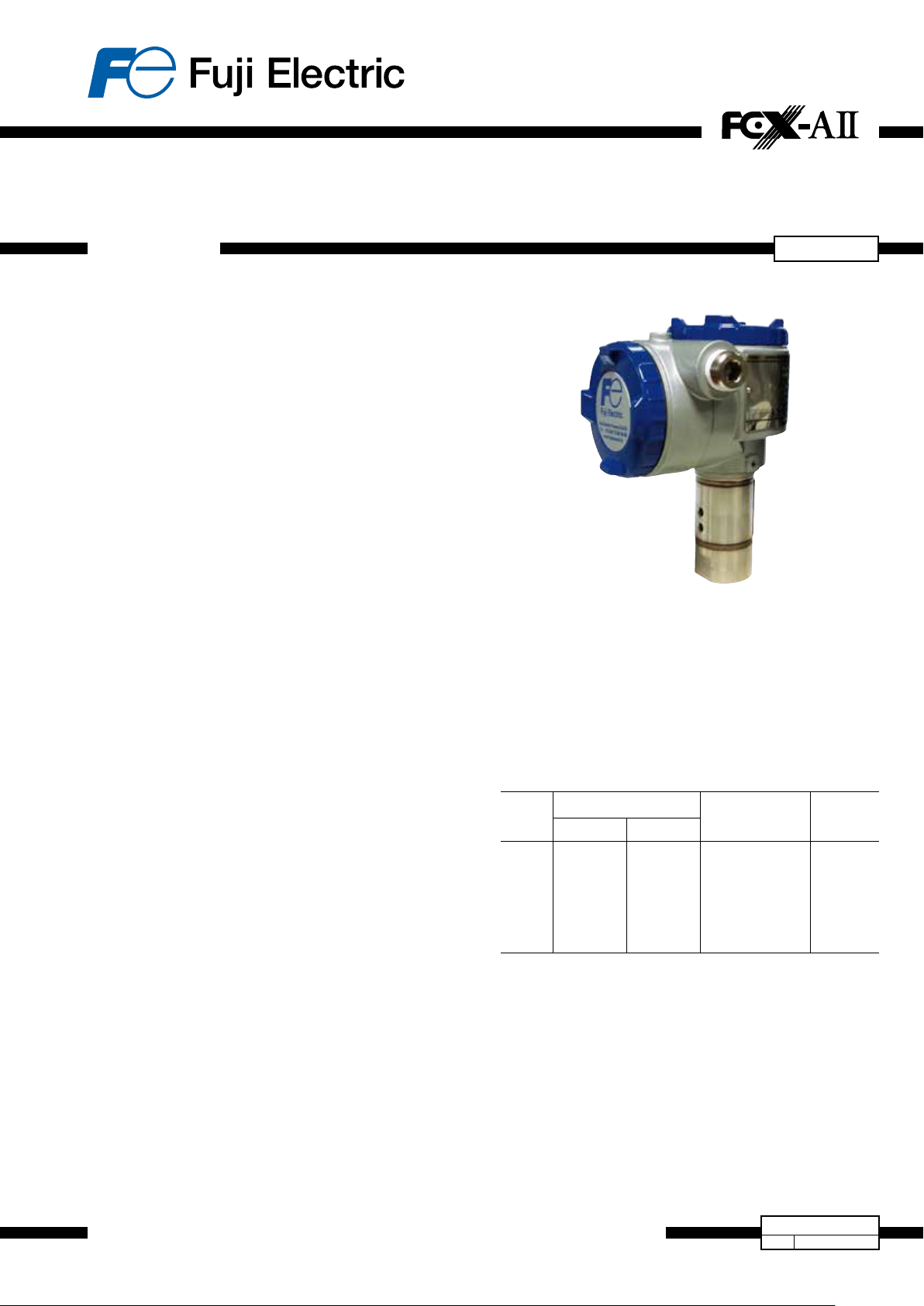
PRESSURETRANSMITTER(DIRECTMOUNTTYPE)
DATA SHEET
The FCX-AII pressure transmitter accurately measures
gauge pressure and transmits proportional 4 to 20 mA
signal.
The transmitter utilizes the unique micromachined capacitive
silicon sensor with state-of-the-art microprocessor technology
to provide exceptional performance and functionality.
FEATURES
1. High accuracy ±0.1%
0.1% accuracy is a standard feature. Fuji’s micro-capacitance
silicon sensor assures this accuracy for all elevated or suppressed calibration ranges without additional adjustment.
2. Minimum inventory and design
Electronics unit, local indicators and electronics housing are
interchageable among all FCX-AII transmitters.
3.Minimumenvironmentalinuence
The “Advance Floating Cell” design which protects the pres-
sure sensor against changes in temperature, and overpressure substantially reduces total measurement error in actual
eld applications.
4. Fuji/HART
FCX-AII series transmitter offers bilingual communications to
speak both Fuji proprietary protocol and HART
Any HART
AII.
5.Applicationexibility
Various options that render the FCX-AII suitable for almost
any process applications include:
– Analog indicator at either the electronics side or terminal
– Full range of hazardous area approvals
– Built-in RFI lter and lightning arrester
– 5 digit LCD meter with engineering unit
– Stainless steel electronics housing
– Wide selection of materials
6. Programmable output Linearization Function
Output signal can be freely programmable.
(Up to 14 compensated points at approximation)
7.Burnoutcurrentexibility(Under Scale: 3.2 to 4.0 mA,
OverScale:20.0to22.5mA)
Burnout signal level is adjustable using Model FXW or Hand
Held Communicator (HHC) to comply with NAMUR NE43.
8. Dry calibration without reference pressure
Thanks to the best combination of unique construction
of mechanical parts (Sensor unit) and high performance
electronics circuit (Electronics unit), reliability of dry
calibration without reference pressure is at equal level as
wet calibration.
side
®
bilingual communications protocol
®
®
compatible devices can communicate with FCX-
.
...
FKP
5
SPECIFICATIONS
Functionalspecications
Type:
FKP: Smart, 4 to 20 mA DC + Fuji/Hart
Service:
Liquid, gas, or vapour
Span,rangeandoverrangelimit:
Type
FKP01
FKP02
FKP03
FKP04
Span limit kPa {bar}
Min.
8.125
{0.08125}
31.25
{0.3125}
187.5
{1.875}
625
{6.25}
Max.
130
{1.3}
500
{5}
3000
{30}
10000
{100}
Range limit
kPa {bar}
-100 to + 130
-100 to + 500
-100 to + 3000
-100 to +10000
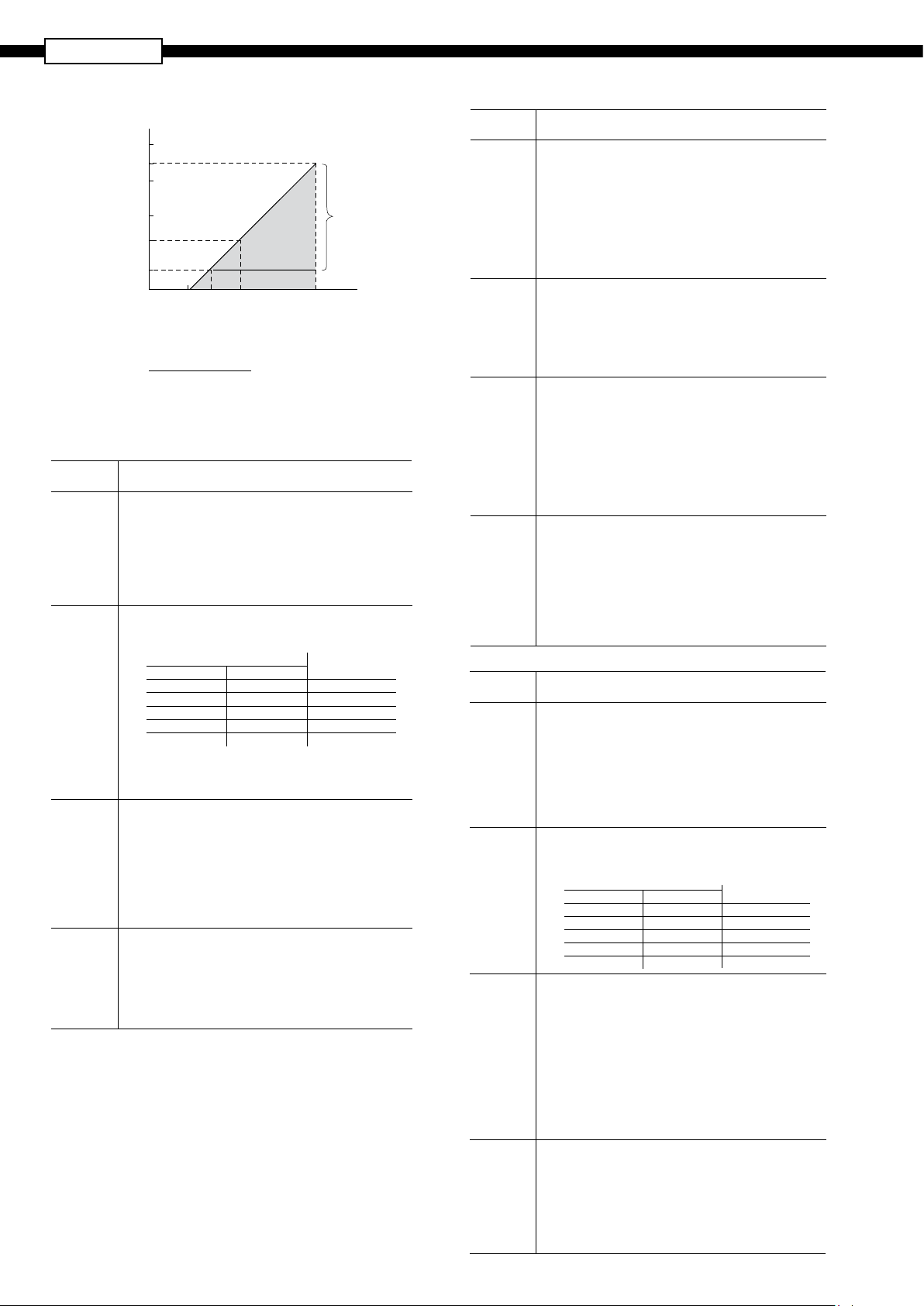
Lower range limit (vacuum limit) is:
Silicone ll sensor: See Fig. 1
Fluorinated ll sensor: 66 kPa abs (500mmHg abs) at
below 60°C
Outputsignal:
4 to 20 mA DC with digital signal superimposed on the
analogic signal
Powersupply:
Transmitter operates on 10.5 to 45 V DC at transmitter
terminals.
10.5 to 32 V DC for the units with optional arrester
®
digital signal
{-1 to +1.3}
{-1 to +5}
{-1 to +30}
{-1 to +100}
Overrange
limit
MPa {bar}
1
{10}
1.5
{15}
9
{90}
15
{150}
Fuji Electric France S.A.S.
EDSF5-98i
October,2015Date
Page 2
...
FKP
5
Loadlimitations: see gure below
When the upper limit of the saturation
R [Ω]
2000
1533
1500
1000
Load resistance
Note) The load resistance varies with the upper limit
of the saturation current [I max]
R [Ω] =
Note: For communication with HHC
required.
current (Imax) is 21.6 mA
600
250
0
10.6 16.1
E [V] -10.5
(I max [mA]+0.9)x10
24 45
-3
Hazardouslocations:
Authority
(Digit 10 = )
ATEX
(K)
Factory
Mutual
(H)
CSA
(J)
IECEx
(T)
Ex II 1 G
Ex ia IIC T5 (-40°C ≤ Ta ≤ +50 °C)
Ex ia IIC T4 (-40°C ≤ Ta ≤ +70 °C)
IP66/67
Entity Parameters:
Ui ≤ 28 Vdc, Ii ≤ 94.3 mA, Pi ≤ 0.66 W
Ci = 36 nF/26 nF for models with/without Arrester
Li = 0.7 mH/0.6 mH for models with/without Analog Indicator
Class I II III
Div.1 Groups A, B, C, D, E, F, G
T4 Entity Type 4X
Model code
9th digit 13th digit
A,B,C,D,J Y,G,N -40°C to +85°C
L,P,M,1,2,3 Y,G,N -20°C to +80°C
Q,S,N,4,5,6 Y,G,N -20°C to +60°C
E,F,G,H,K Y,G,N -40°C to +60°C
- W,A,D -10°C to +60°C
Entity Parameters:
Vmax=42.4V, Imax=113mA, Pi=1W,
Ci=35.98nF, Li=0.694mH
Ex ia Class I, Groups A, B, C and D;
Class II, Groups E,F and G; Class III
Per drawing TC 522873
Temp. code T5 for Tamb max = +50°C
Temp. code T4 for Tamb max = +70°C
Entity Parameters:
Vmax = 28 Vdc, Imax = 94.3 mA, Pmax = 0.66 W
Ci = 36 nF/25 nF for models with/without Arrester
Li = 0.7 mH/0.6 mH for models with/without Analog Indicator
Ex ia IIC T5 (-40°C ≤ Ta ≤+50 °C)
Ex ia IIC T4 (-40°C ≤ Ta ≤+70 °C)
IP66/67
Entity Parameters:
Ui ≤ 28 Vdc, Ii ≤ 94.3 mA, Pi ≤ 0.66 W
Ci = 36 nF/26 nF for models with/without Arrester
Li = 0.7 mH/0.6 mH for models with/without Analog Indicator
Intrinsic safety
Communication
Operating
area
Power voltage
(1)
(model: FXW), min. of 250 W
range with HHC
E [V]
Tamb
Authority Flameproof
ATEX
(X)
Factory
Mutual
(D)
CSA
(E)
IECEx
(R)
Authority
(Digit 10 = )
ATEX
(P)
Factory
Mutual
(H)
CSA
(J)
IECEx
(Q)
Ex II 2 GD
Ex d IIC T6 (-40°C ≤ Ta ≤ +65 °C)
Ex d IIC T5 (-40°C ≤ Ta ≤ +85 °C)
Ex tD A21 IP66/67 T 85°C
Ex tD A21 IP66/67 T 100°C
Electrical ratings
Model Without arrester:
Ui ≤ 45 Vdc, 4-20 mA loop powered, Pi ≤ 1.0125 W
Model With arrester:
Ui ≤ 32 Vdc, 4-20 mA loop powered, Pi ≤ 1.0125 W
Class I
Div.1 Groups B, C, D
T6 Type 4X
Class II III
Div.1 Groups E, F, G
T6 Type 4X
Tamb max = +60°C
Class I, Groups C and D;
Class II, Groups E,F and G ; Class III
Maximum ambient temperature 85°C
Maximum working pressure 50 Mpa
Electrical ratings
Model Without arrester:
Ui ≤ 45 Vdc, 4-20 mA
Model With arrester:
Ui ≤ 32 Vdc, 4-20 mA
Note: "Seal not required"
Ex d IIC T6 (-40°C ≤ Ta ≤ +65 °C)
Ex d IIC T5 (-40°C ≤ Ta ≤ +85 °C)
DIP A21 IP66/67 T 85°C
DIP A21 IP66/67 T 100°C
Electrical ratings
Model Without arrester:
Ui ≤ 45 Vdc, 4-20 mA loop powered, Pi ≤ 1.0125 W
Model With arrester:
Ui ≤ 32 Vdc, 4-20 mA loop powered, Pi ≤ 1.0125 W
Type n
Nonincendive
Ex II 3 G
Ex nA II T5 (-40°C ≤ Ta ≤+70 °C)
IP66/67
Electrical ratings
Model Without arrester:
Ui ≤ 45 Vdc, 4-20 mA loop powered, Pi ≤ 1.0125 W
Model With arrester:
Ui ≤ 32 Vdc, 4-20 mA loop powered, Pi ≤ 1.0125 W
Optional Analog indicator is not available for type "n"
Class I II III
Div.2 Groups A, B, C, D, F, G
T4 Entity Type 4X
Model code
9th digit 13th digit
A,B,C,D,J Y,G,N -40°C to +85°C
L,P,M,1,2,3 Y,G,N -20°C to +80°C
Q,S,N,4,5,6 Y,G,N -20°C to +60°C
E,F,G,H,K Y,G,N -40°C to +60°C
- W,A,D -10°C to +60°C
Class I
Div.2 Groups A, B, C, D
Class II
Div.2 Groups E, F, G
Class III
Div.2
Temp Code T5 Tamb max = +50°C
Temp Code T4 Tamb max = +70°C
Entity Parameters:
Vmax = 28 Vdc, Imax = 94.3 mA, Pmax = 0.66 W
Ci = 36 nF/25 nF for models with/without Arrester
Li = 0.7 mH/0.6 mH for models with/without Analog Indicator
Ex nA II T5 (-40°C ≤ Ta ≤+70 °C)
IP66/67
Electrical ratings
Model Without arrester:
Ui ≤ 45 Vdc, 4-20 mA loop powered, Pi ≤ 1.0125 W
Model With arrester:
Ui ≤ 32 Vdc, 4-20 mA loop powered, Pi ≤ 1.0125 W
Optional Analog indicator is not available for type "n"
Tamb
2
Page 3
Zero/span adjustment:
Zero and span are adjustable from the HHC
(1)
. Zero and
span are also adjustable externally from the adjustment
screw.
Damping:
Adjustable from HHC
(1)
or local adjustment unit with LCD
display.
The time constant is adjustable between 0,06 to 32 sec.
Zeroelevation/suppression:
-100% to +100% of URL
Normal/reverseaction:
Selectable from HHC
(1)
.
Indication:
Analog indicator or 5 digit LCD meter, as specied.
Burnoutdirection: Selectable from HHC
(1)
If self-diagnostic detect transmitter failure, the analog
signal will be driven to either “Output Hold”, “Output Overscale” or “Output Underscale” modes.
“Output Hold”:
Output signal is hold as the value just before failure hap-
pens.
“Output Overscale”:
Adjustable within the range 20.0 to 22.5 mA from HHC
(1)
“Output Underscale”:
Adjustable within the range 3.2 to 4.0 mA from HHC
3.2
Under scale
Burnout
4
Normal operating range
Probable under range
20 22.5 [mA]
Probable over range
(1)
Over scale
Burnout
Output limits conforming to NAMUR NE43 by order.
Loop-checkoutput:
Transmitter can be congured to provide constant signal
3.2 through 22.5 mA by HHC.
Temperaturelimit:
Ambient: -
40 to +85°C
-20 to +80°C (for LCD indicator)
-
40 to +60°C (for arrester option)
-10 to +60°C (for uorinated oil ll transmitter)
For explosionproof units (ameproof or intrinsic safety),
ambient temperature must be within the limits specied by
each standard.
Process:
-
40 to +100°C for silicone oil ll sensor
-20 to +80°C for uorinated oil ll sensor
Storage: -40 to +90°C
Humiditylimit:
0 to 100% RH (Relative Humidity)
Communication:
With HHC
(1)
(Model FXW, consult DS n° EDS8-47),
following items can be remotely displayed or congured.
Note: HHC’s version must be higher than 7.0 (or
FXW
1– 4), for FCX-AII for supporting these
items: “Saturate current”, “Write protect”, and “History”.
Items
Tag No. v v v v v v
Model No. v v v v v v
Serial No. & Software
Version
Engineering unit v v v v v v
Range limit v — v — v —
Measuring range v v v v v v
Damping v v v v v v
Output
mode
Linear v v v v v v
Square root v v v v v v
Fuji Protocol
with FXW
Display Set Display Set Display Set
v — v — v —
Hart® Protocol
By local configurator (with 3 push
button), (LCD in
dicator)
Burnout direction v v v v v v
Calibration v v v v v v
Output adjust — v — v — v
Data v — v — v —
Self diagnoses v — v — v —
Printer (In case of FXW
with printer option)
External switch lock v v v v v v
Transmitter display v v v v v v
Linearize* v v — — — —
Rerange v v v v v v
Saturate current v v v v v v
Write protect v v v v v v
History
– Calibration history
– Ambient temperature
history
(Note) (1) HHC: Hand Held Communicator
v — — — — —
vvv—vvv—v
LocalconguratorwithLCDdisplay(option):
Local congurator with 3 push button and LCD display
can support all items (Fuji Protocol list) except “Linearize”
function.
Programmableoutputlinearizationfunction:
Output signal can be characterized with “14 points linear
approximation function” from HHC
(1)
.
Performancespecications
Reference conditions, silicone oil fill, SS 316L isolating dia-
phragms, 4 to 20 mA analog output in linear mode.
Accuracyrating:
(including linearity, hysteresis, and repeatability)
For spans greater than 1/10 of URL:
±0.1% of span
For spans below 1/10 of URL :
± (0.05 + 0.05 ) % of span
Stability:
±0.2% of upper range limit (URL) for 10 years (In case of
6th digit code “2”, “3”, “4”)
Temperatureeffect:
Effects per 55°C change between the limits of - 40°C and
+85°C
Zero shift :
± (0.4 + 0.1 )% / 28°C
Total effect:
± (0.475 + 0.1 )% / 28°C
-
Overrangeeffect:
Zero shift, 0.3% of URL for any overrange to maximum
limit
Supplyvoltageeffect:
Less than 0.05% fo calibrated span per 10 V
Updaterate:
60 msec
RFIeffect:
< 0,2% of URL for the frequences of 20 to 1000 MHz and
eld strength of 10 V/m when electronic housing covers
are on (Classication : 2-abc : 0,2% of span according
SAMA PMC 33.1)
0.1 x URL
URL
span
URL
span
span
vv—
3
Page 4

FKP
...
5
Responsetime:(without electrical damping)
Time constant. 0.08 seconds (at 23°C)
Dead time: about 0.12 seconds
Response time = time constant + dead time
Mountingpositioneffect:
Zero shift, less than 0.1 kPa {1mbar} for a 10° tilt in any
plane.
This error can be corrected by adjusting zero.
(Double the effect for uorinated ll sensors).
No effect on span.
Vibrationeffect:
< ±0,25% Of spans for spans greater than 1/10 of URL.
Frequency 10 to 150 Hz, acceleration 39,2 m/sec
2
Materialfatigue:
Please consult Fuji Electric.
Dielectricstrength:
500 V AC, 50/60 Hz 1 min., between circuit and earth
Insulationresistance:
More than 100 MW at 500 V DC
Internalresistanceforexternaleldindicator:
12Ω Max (connected to test terminal CK+ and CK-).
Pressureequipmentdirective(PED)97/23/EC:
According to Article 3.3
Physicalspecications
Electricalconnections:
1/2"-14 NPT, Pg13.5, or M20×1.5
Processconnections:
1/2-14 NPT, 1/4-18 NPT, Rc 1/2, G1/2 A manometer t-
ting, M20 x 1,5.
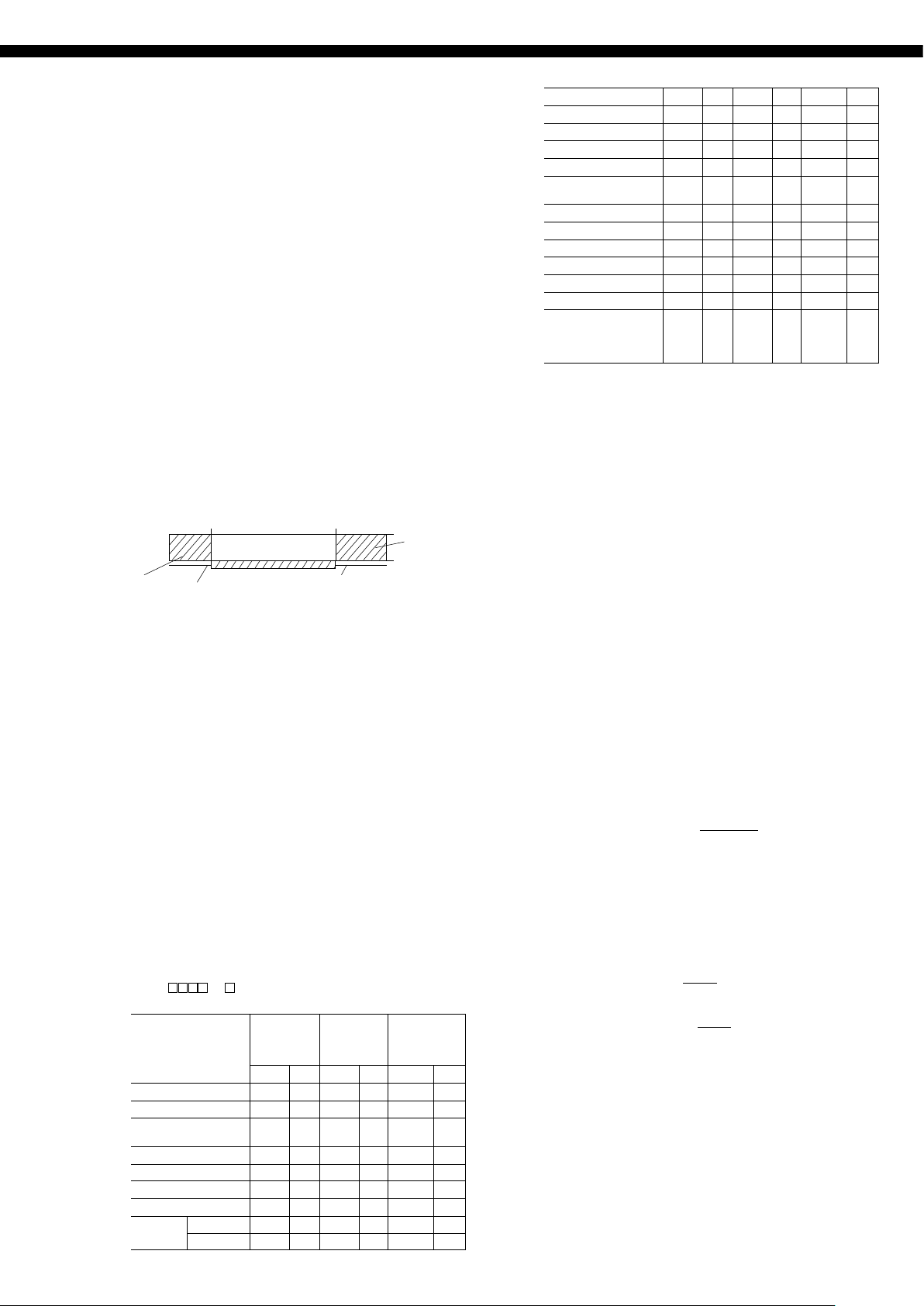
Process-wettedpartsmaterial:
Material code
(7th digit
in Code
symbols)
J
V
Process cover Diaphragm
SS 316L
SS 316L
SS 316L +
Gold coating
SS 316L
Non-wettedpartsmaterial:
Electronics housing:
Low copper die-cast aluminum alloy , nished with
polyester coating (standard), or SS 316L as specied.
Fill uid:
Silicone oil (standard) or uorinated oil (option)
Mounting bracket:
SS 304L
SS 316L (option)
Environmentalprotection:
IEC IP66/IP67 and NEMA4X
Mounting:
Without mounting bracket : direct mounting on manifold
(optional)
With optional mounting bracket : for 50 mm (2”) pipe or
direct wall mounting
Mass{weight}:
Transmitter approximately : 1,7 kg without options.
Add; 0.5 kg for indicator
0.5 kg for mounting bracket
2 kg for stainless steel housing option
Wetted
sensor body
SS 316L
SS 316L
Optional features
Indicator:
A plug-in analog indicator (2.5% accuracy) can be housed
in the electronics compartment or in the terminal box of the
housing.
An optional 5 digit LCD meter with engineering unit is also
available.
LocalconguratorwithLCDdisplay:
An optional 5 digits LCD meter with 3 push buttons can
support items without using communication with HHC.
Arrester:
A built-in arrester protects the electronics from lightning
surges.
Lightning surge immunity: 4 kV (1.2 x 50 µs)
Oxygenservice:
Special cleaning procedures are followed throughout the
process to maintain all process wetted parts oil-free.
The ll uid is uorinated oil.
Degreasing:
Process-wetted parts are cleaned, but the fill fluid is
standard silicone oil. Not for use for oxygen or chlorine
measurement.
NACEspecication:
Metallic materials for all pressure boundary parts comply
with NACE MR 0175 / ISO 15156.
SS 660 or SS 660/660 bolts and nuts comply with NACE
MR 0175 / ISO 15156.
Optionaltagplate:
An extra stainless steel tag with customer tag data is wired
to the transmitter.
Vacuumservice:
Special silicone oil and lling procedure are applied.
Silicone oil (Code:Y,G,N)
[kPa abs]
(mmHg abs)
101
(760)
Operating
20
(150)
4
Operating pressure
(30)
2.7
(20)
−40 60 100
Process temperature [°C ]
Fig.1 Relation between process temperature and operating pressure
area
None-operating
area
ACCESSORIES
Hand-heldcommunicator:
(Model FXW, refer to DSt n° EDS8-47)
4
Page 5

CODESYMBOLS
1 2 3 4 5 6 7 8 9 10 11 12 13 14 15
F K P
0 5 - - 0
T See digit 15 1/2-14 NPT
V See digit 15 Pg 13,5
W See digit 15 M 20 x 1,5
0 1 V 0,08125/1,3 bar
0 1 J 0,08125/1,3 bar
0 2 V 0,3125/5 bar
0 2 J 0,3125/5 bar
0 3 V 1,875/30 bar
0 3 J 1,875/30 bar
0 4 V 6,25/100 bar
0 4 J 6,25/100 bar
5 - A None None
5 - B Analog, 0-100% linear scale None
5 - D Analog, Custom scale None
5 - J Analog, double scale None
5 - E None Yes 4-20 mA DC
5 - F Analog, 0-100% linear scale Yes
5 - H Analog, Custom scale Yes +
5 - K Analog, double scale Yes
5 - L Digital, 0-100% None
5 - P Digital, Custom scale None
5 - Q Digital, 0-100% Yes
5 - S Digital, Custom scale Yes
5 - 1 Digital, 0-100% with push button None
5 - 2 Digital, Custom scale with push button None
5 - 4 Digital, 0-100% with push button Yes
5 - 5 Digital, Custom scale with push button Ye s
A
X
K
D
E
H
J
P
Q
R
T
L
M
N
V
A None
C Yes (SS 304L)
Y None None
B Yes None
C None Ye s
E Yes Yes
Y None (std) Silicone oil
G Degreasing Silicone oil
A Oxygen service Fluorinated oil
N NACE Silicone oil
- 0 Y 1/2 - 14 NPTI
- 0 B Rc 1/2 I
- 0 C 1/4 - 18 NPTI
- 0 D 1/2 - 14 NPTE
- 0 E G 1/2“A manometer fitting
- 0 F M20 x 1,5
Type
Smart, 4-20 mAdc + Fuji/Hart
Connections
Process Electrical
connection connection
Range & wetted parts material
Span
Indicator & Arrester
Indicator Arrester Initial setting
Approvals for hazardous locations (consult FUJI for availability)
None (Standard)
ATEX - Flameproof enclosures (digit 4 = "T" & "W" only)
ATEX - Intrinsic Safety
(*1)
FM - Explosion-Proof (digit 4 = "T" only)
CSA - Explosion-Proof (digit 4 = "T" only)
FM - Intrinsic Safety and Non Incendive
CSA - Intrinsic Safety
ATEX - Type "n" (digit 9 = A, E, 1, 2, 3, 4 & 5 only)
IECEx - Type "n" (digit 9 = A, E, 1, 2, 3, 4 & 5 only)
IECEx - Flameproof enclosures (digit 4 = "T" & "W" only)
IECEx - Intrinsic Safety
CSA - Explosion-Proof & Intrinsic Safety combined approval (digit 4 = "T" only)
ATEX - Flameproof enclosures & Intrinsic Safety combined approval (digit 4 = "T" & "W" only)
IECEx - Flameproof enclosures & Intrinsic Safety combined approval (digit 4 = "T" & "W" only)
FM - Explosion-Proof & Intrinsic Safety combined approval (digit 4 = "T" only)
Mounting bracket
Stainless Steel parts
Tag plate Housing
Special applications & fill fluid
Treatment Fill fluid
Processconnection (welded) adaptor - all stainless steel parts
®
digital signal
Diaphragm material
SS 316L
SS 316L / gold coat
SS 316L
SS 316L / gold coat
SS 316L
SS 316L / gold coat
SS 316L
SS 316L / gold coat
DESCRIPTION
Wetted parts
SS 316L
SS 316L
SS 316L
SS 316L
SS 316L
SS 316L
SS 316L
SS 316L
®
Hart
/Fuji
digital signal
"SMART"
Note* :
1 - Codes "D" and "V" , FM approval only possible with electrical connection 1/2"-14 NPT.
5
Page 6

FKP
...
5
OUTLINE DIAGRAM
(Unit:mm)
ELECTRICAL CONNECTION
D
E
E
D
WEIGHT :
1,7 KG (WITHOUT OPTION)
ADD : - 0,5 KG FOR MOUNTING BRACKET
- 2 KG FOR STAINLESS STEEL HOUSING OPTION
6
Page 7

Details "A" - Process connection
CONNECTION DIAGRAM
7
Page 8

...
Mail : sales.dpt@fujielectric.fr - web : www.fujielectric.fr
FKP
EMCDirective(2004/108/EC)
All models of FCX series transmitters type FCX-AII are in accordance with :
• the harmonized standards:
- EN 61326-1 : 2006 (Electrical equipment for measurement, control and laboratory use - EMC requirements).
- EN 61326-2-3 : 2006 (Part 2-3 : Particular requirements - Test conguration, operational conditions and performance
criteria for tranducers with integrated or remote signal conditioning)
Emission limits:EN 61326-1 : 2006
Frequency range (MHz) Limits Basic standard
30 to 230 40 dB (µV/m) quasi peack, measured at 10m distance EN 55011 / CISPR 11
Group 1 Class A
230 to 1000 47 dB (µV/m) quasi peack, measured at 10m distance
Immunity requirements:EN 61326-1 : 2006 (Table 2)
Phenomenon Test value Basic standard Performance criteria
Electrostatic discharge (EDS) 4 kV (Contact) EN 61000-4-2 B
8 kV (Air) IEC 61000-4-2
Electromagnetic eld 10V/m (80 to 1000 MHz) EN 61000-4-3
3 V/m (1.4 to 2.0 GHz) IEC 61000-4-3 A
1 V/m (2.0 to 2.7 GHz)
Rated power frequency 30 A/m EN 61000-4-8 A
Magnetic eld IEC 61000-4-8
Burst 2 kV (5/50 NS, 5 kHz EN 61000-4-4 B
IEC 61000-4-4
Surge 1 kV Line to line EN 61000-4-5 B
2 kV Line to line IEC61000-4-5
Conducted RF 3 V (150 kHz to 80 MHz) EN 61000-4-6 A
IEC61000-4-6
Performance criteria :
A : During testing, normal performance within the specication limits.
B : During testing, temporary degradation or loss of function or performance which is self-recovering.
5
Fuji Electric France S.A.S.
46 rue Georges Besse - ZI du brézet - 63039 Clermont ferrand
Tél : 04 73 98 26 98 - Fax : 04 73 98 26 99
Fuji Electric can accept no responsibility for possible errors in catalogues, brochures and other printed material. Fuji Electric reserves the right to alter its products without notice. This also applies to products already on order provided that such alterations can be made without subsequential changes being necessary
in specications already agreed. All trademarks in this material are property of the respective companies. All rights reseved.
 Loading...