

Page 1
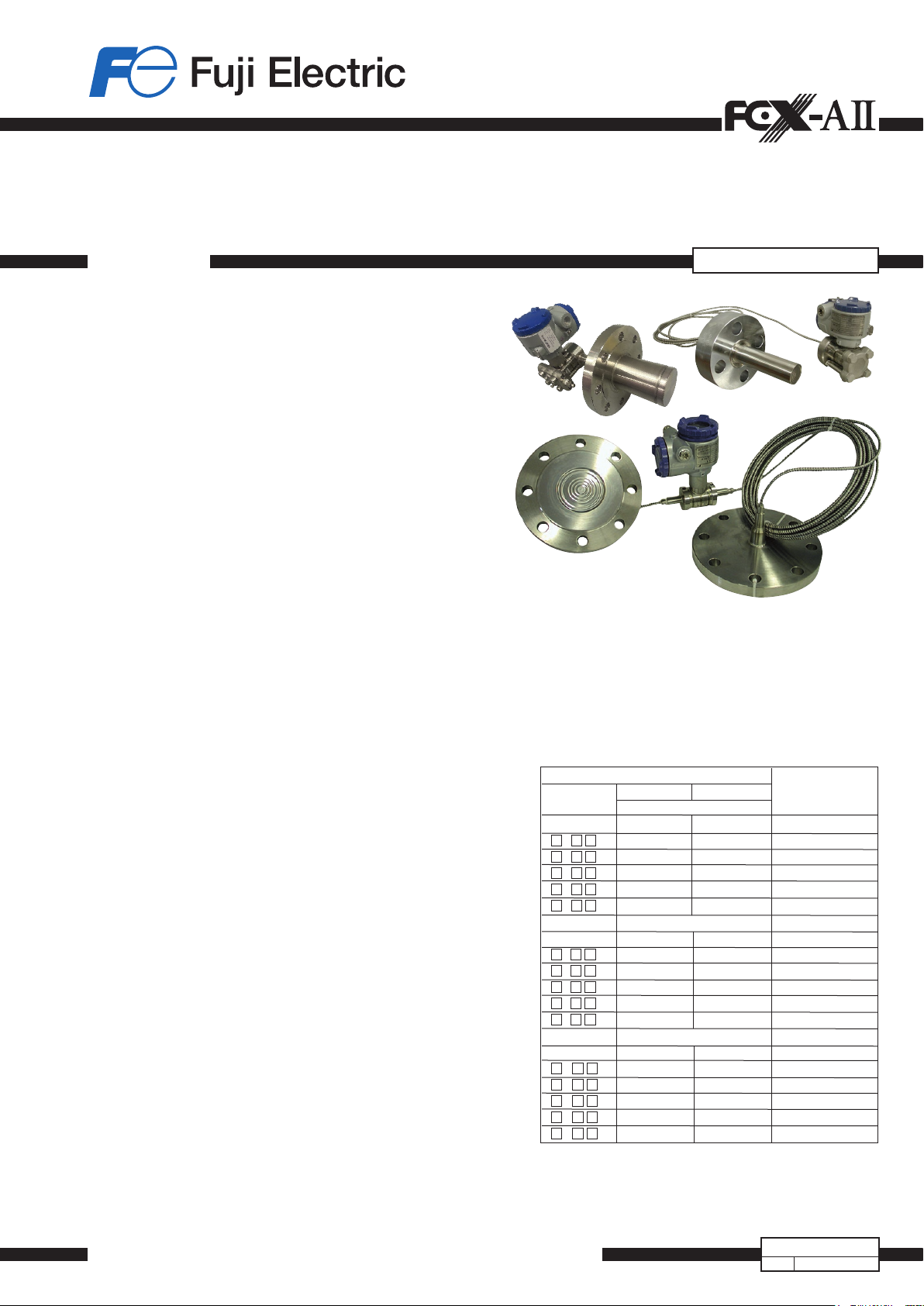
ABSOLUTE, DIFFERENTIAL AND GAUGE PRESSURE
TRANSMITTER FOR REMOTE SEAL(S)
DATA SHEET
FKB, FKD and FKM models of FCX-AII V5 series of pressure
transmitters accurately measure a gauge, differential or absolute
pressure and transmit a proportional 4-20 mA output signal.
The transmitters use an unique micro-capacitive silicon
sensor in combination with a state-of-the-art digital signal
processing to provide exceptional performances in
terms of accuracy and stability.
FEATURES
1. High accuracy
The Fuji Electric’s micro-capacitive sillicon sensor provides
in standard ±0.065% accuracy for differential and gauge
transmitter models and ±0.2% accuracy for the absolute
transmitter model, for all elavated or supressed calibration
ranges without additional adjustments.
2. Minimum inventory and design
Electronics unit, local indicators and electronics housing
are interchageable among all FCX-AII transmitters.
Fuji Electric remote seals design are based on a welded
conception that provides a reduced and optimized volume
ange to guarantee a perfect vaccum tightness and high
pressure services.
3.Minimumenvironmentalinuence
The Advanced Floating Cell technology provides a high
immunity against temperature variations and overpressure
commonly found in the process industry and substantially
reduces the overall measurement error.
4. HART/Fuji Electric communication protocols
FCX-AII V5 series of pressure transmitters can communicate
using either the universal HART or the proprietary and faster
Fuji Electric communication protocol.
By the use of Device Description files, HART compatible
devices can communicate with any FCX-AII V5 transmitter.
5.Applicationexibility
Various options are available to address most of the pro-
cess industry applications, including :
- Full range of hazardous area approvals
- Built-in RFI lter and lightning arrester
- Analog or 5 digits local indicator with engineering unit
- Stainless steel electronics housing
- Wide selection of materials
- High temperature, high vacuum seals
6. Programmable output Linearization Function
The output signal can be linearized using up to 14 pairpoints.
7.Burnoutcurrentexibility
The burnout current value can be adjusted in the ranges of
[3.2 ; 4.0] and [20.0 ; 22.5] mA and can be compliant with
NAMUR NE43 recommandations.
FKB, FKD, FKM...F
FUNCTIONAL SPECIFICATIONS
Type:
- FKD : differential pressure transmitter with remote seal(s)
- FKB : gauge pressure transmitter with remote seal
- FKM : absolute pressure transmitter with remote seal
Service :
Liquid, gas, or vapour
Span, range, and overrange limit :
Span limits Range limits
Model Minimum Maximum
FKD
(mbar) (mbar) (mbar)
F
D 3 3.2 320 ± 320
F
D 5 13 1300 ± 1300
F
D 6 50 5000 ± 5000
F
D 8 300 30000 ± 30000
F
D 9* 2000 200000 ±200000
FKB
(bar) (bar) (bar)
F
B 1 0.013 1,3 -1 to + 1,3
F
B 2 0.05 5 -1 to + 5
F
B 3 0.3 30 -1 to + 30
F
B 4 1 100 -1 to + 100
F
B 5 5 500 -1 to + 500
FKM
(bar abs) (bar abs) (bar abs)
F
M 1 0.016 0.16 0 to +0,16
F
M 2 0.013 1,3 0 to +1,3
F
M 3 0.05 5 0 to +5
F
M 4 0,3 30 0 to +30
F
M 5 1 100 0 to +100
Remark : To minimize environmental influence, span should be greater than
Important : For FKD#49, maximum possible overload pressure on LP side must be
1/40 of the max. span in most applications.
≤ 100 bar. The accuracy is not guaranteed when used at negative DP.
Fuji Electric France S.A.S.
EDSF6-05n
July, 2018
Date
Page 2
FKB, FKD, FKM...F
R [Ω]
Load resistance
Held Communicator
load of 250 Ω is required.
Output signal :
4-20 mA with digital signal super imposed on the ana-
log signal.
Power supply :
10.5 to 45 V DC at transmitter terminals.
10.5 to 32 V DC with the optional arrester.
Refer to hazardous location table for specic limitations.
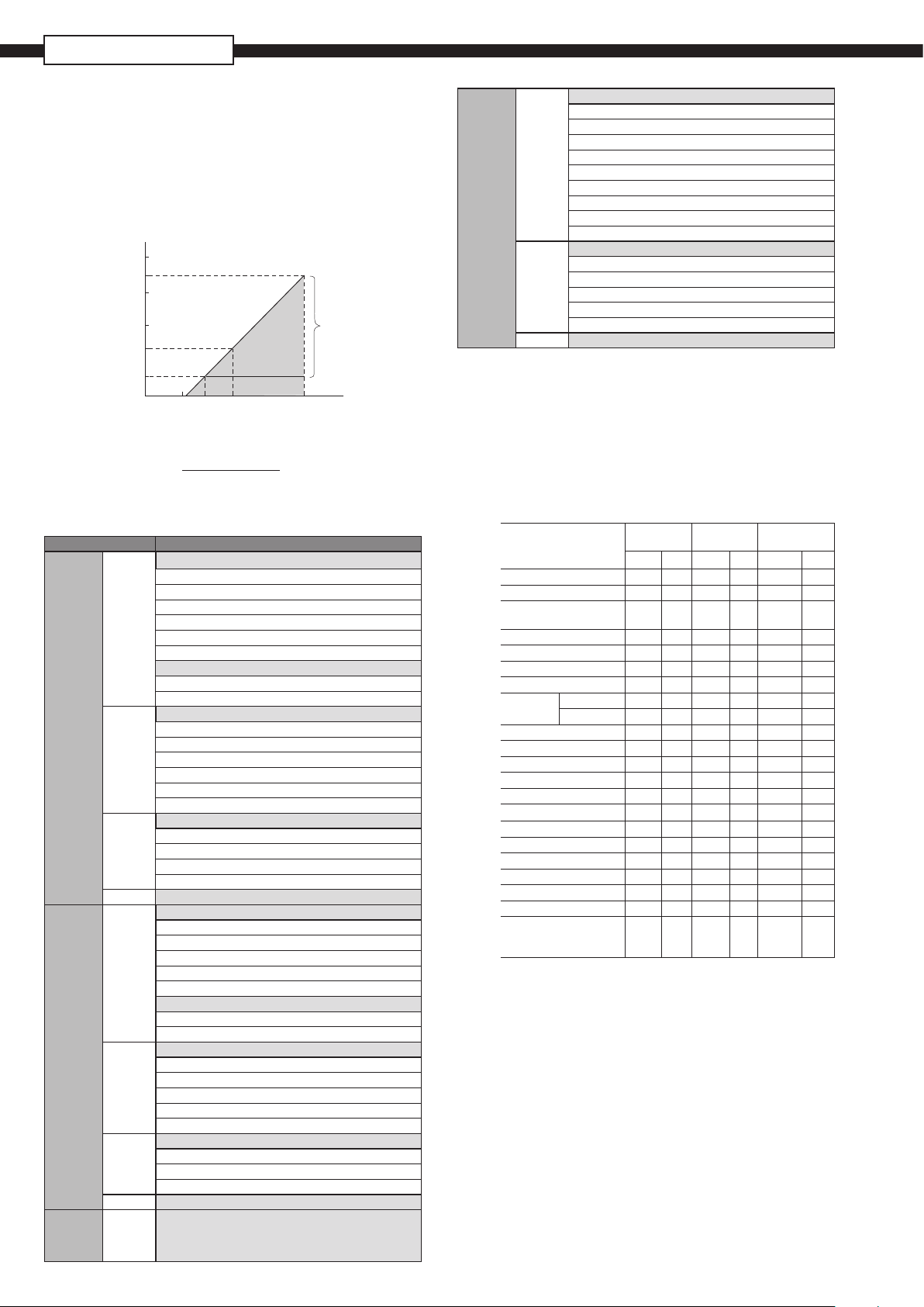
Load limitations : see gure below
When the upper limit of the saturation
current (Imax) is 21.6 mA
2000
1533
1500
1000
600
250
0
10.6 16.1
Note 1 : The load resistance varies with the upper limit of
the saturation current [I max]
R [Ω] =
(I max [mA]+0.9)x10
Note 2 : For communication with HHC (FXW model), a minimum
Operating
area
24 45
E [V] -10.5
-3
Communication
range with Hand
(HHC)
Power voltage
Hazardous locations :
Marking (Digit 10 =) Protection type
ATEX
Intrinsic Safety “i” :
Ex II 1G/D
Ex ia IIC T4 Ga (-40°C ≤ Ta ≤ +70°C)
Ex ia IIC T5 Ga (-40°C ≤ Ta ≤ +50°C)
Ex ia IIIC T135°C Da (-40°C ≤ Ta ≤ +70°C)
(K)
Ex ia IIIC T100°C Da (-40°C ≤ Ta ≤ +50°C)
IP 66/67
Electrical Parameters :
Ui ≤ 28 Vdc, Ii ≤ 94.3 mA, Pi ≤ 0.66 W
Ci = 26 nF
/ 36 nF
(2)
, Li = 0.6 mH
(3)
/ 0.7 mH
(1)
Flameproof Enclosure “d”:
Ex II 2G/D
Ex d IIC T5 Gb (-40°C ≤ Ta ≤ +85°C)
(X)
Ex d IIC T6 Gb (-40°C ≤ Ta ≤ +65°C)
Ex tb IIIC T100°C Db (-40°C ≤ Ta ≤ +85°C)
Ex tb IIIC T85°C Db (-40°C ≤ Ta ≤ +65°C)
45 Vdc max
Increased Safety “e” :
Ex II 3G/D
(P)
Ex ec IIC T5 Gc (-40°C ≤ Ta ≤ +70°C)
Ex tc IIIC T100°C Dc (-40°C ≤ Ta ≤ +70°C)
45 Vdc max
(M) Combination (K) + (X)
IECEx
Intrinsic Safety “i”:
Ex ia IIC T4 Ga (-40°C ≤ Ta ≤ +70°C)
Ex ia IIC T5 Ga (-40°C ≤ Ta ≤ +50°C)
Ex ia IIIC T135°C Da (-40°C ≤ Ta ≤ +70°C)
(T)
Ex ia IIIC T100°C Da (-40°C ≤ Ta ≤ +50°C)
IP 66/67
Electrical Parameters :
Ui ≤ 28 Vdc, Ii ≤ 94.3 mA, Pi ≤ 0.66 W
(1)
Ci = 26 nF
/ 36 nF
(2)
, Li = 0.6 mH
(3)
/ 0.7 mH
Flameproof Enclosure “d”:
Ex d IIC T5 Gb (-40°C ≤ Ta ≤ +85°C)
Ex d IIC T6 Gb (-40°C ≤ Ta ≤ +65°C)
(R)
Ex tb IIIC T100°C Db (-40°C ≤ Ta ≤ +85°C)
Ex tb IIIC T85°C Db (-40°C ≤ Ta ≤ +65°C)
45 Vdc max
Increased Safety “e” :
Ex ec IIC T5 Gc (-40°C ≤ Ta ≤ +70°C)
(Q)
Ex tc IIIC T100°C Dc (-40°C ≤ Ta ≤ +70°C)
45 Vdc max
(N) Combination (T) + (R)
ATEX
IECEx
(W) Combination (K) + (X) + (T) + (R) + (J) + (E)
cCSAus
2
E [V]
cCSAus
Intrinsic safety / Non Incendive / Class 1 Division 2 :
IS Class I Division 1, Groups ABCD Ex ia
Class II Groups EFG; Class III
NI Class I Division 2, Groups ABCD
(Per control drawing TC522873)
(J)
Class I Division 2, Groups ABCD
T4 (-40°C ≤ Ta ≤ +70°C)
T5 (-40°C ≤ Ta ≤ +50°C)
Ui ≤ 28 Vdc, Ii ≤ 94.3 mA, Pi ≤ 0.66 W
Ci = 26nF
/ 36 nF
(2)
, Li = 0.6 mH
(3)
/ 0.7 mH
(4)
(1)
Explosion proof
XP Class I Division 1, Groups CD
Class II Groups EFG; Class III
(E)
T5 (-40°C ≤ Ta ≤ +85°C)
T6 (-40°C ≤ Ta ≤ +65°C)
Vmax = 42.4 Vdc
(L) Combination (J) + (E)
(1) Without optional arrester (3) Without analog indicator
(2) With optional arrester (4) With analog indicator
Conguration:
Conguration of the FCX-AII V5 series of pressure transmitters
can be carried out by either using a Hand Held Terminal
(ie. Fuji Electric FXW or third party HART terminal) or the 3
push-buttons optional indicator.
A third party HART hand held communicator can be used
in combination with Fuji Electric FCX-AII V5 HART Device
Description les (https://eldcommgroup.org).
Functions
Tag Nb v v v v v v
Model Nb v v v v v v
Serial Nb & Software re-
vision
Engineering units v v v v v v
Upper Range Value v — v — v —
Measuring Range v v v v v v
Damping v v v v v v
(4)
Output sig-
nal type
Linear v v v v v v
Square Root v v v v v v
Burnout current v v v v v v
Calibration v v v v v v
Output Adjust — v — v — v
Measuring Value v — v — v —
Self Diagnosis v — v — v —
Printer (option) v — — — — —
External Adj Screw Lock v v v v v v
Transmitter Display v v v v v v
Linearization — — v v v v
Rerange v v v v v v
Saturation Current v v v v v v
Write Protect v v v v v v
History
– Calibration History
– Ambient T° History
Note 1 : The FXW rmware revision must be higher than 7.0 in
order to address FCX-AII V5 “Saturation current”, “Write protect”
and “History” functions.
Note 2 : The “Linearization” function is not accessible throught the
(4)
3 puh-buttons optional indicator.
Damping :
Fuji Electric
FXW
Display Set Display Set Display Set
Third party
HART HHC
3 push buttons
optional indicator
v — v — v —
vvv—vvv
—vvv—
The damping time constant can be adjusted within the
range of [0.06 to 32] seconds.
Zero and span adjustment :
Zero and span are ajustable remotly with a Hand Held
Communicator or locally with the external adjustment screw.
Zero elevation/suppression :
±100 % of the URL for FKD models
-1 bar to +100 % of the URL for FKB models
0 kPa abs to +100 % of the URL for FKM models
Normal/reverse action :
Selectable from a Hand Held Communicator.
Page 3

3.2
21.6 [mA]
Burnout
Saturation
Burnout
Saturation
Burnout and saturation currets :
If the self-diagnostic functions detect a transmitter failure,
the burnout function will drive the output signal to either
“Output Hold”, “Output Overscale” or “Output Underscale”
modes.
When “Output Hold” :
The
output signal is held as the last value just before the failure
happens.
When “Output Overscale” :
The
output signal is set within the range of [20.0 to 22.5] mA
When “Output Underscale” :
The output signal is set within the range of [3.2 to 4.0] mA
Both burnout and saturation current can be adjusted within
the range of [3.2 ; 4.0] and [20.0 ; 22.5] mA
3.6 4
20
Normal operating range
3.8
20.8 22.5
Loop-check/xedoutputcurrents:
The transmitter can be congured to provide a constant
output signal from 3.2 up to 22.5 mA.
Temperature limit :
Ambient :
-40 to +85°C
-20 to +80°C (for LCD indicator)
-40 to +60°C (for arrester option)
-20 to +60°C (for uorinated oil)
Please refer to the hazardous locations table for ambient
temperature limitations according to the standard and type
of protection.
Process :
Refer to the seal specications and the specic tem-
perature conditions.
Storage :
- 40 to +90°C
Humidity limit :
0 to 100% RH (Relative Humidity)
PERFORMANCE SPECIFICATIONS
Reference conditions, silicone oil ll, SS 316L isolating diaphragms,
4-20 mA analog output.
Accuracy rating : (including linearity, hysteresis, and repeatability)
For span > 1/10 of URL :
± 0.065% of calibrated span (FKB & FKD models)
± 0.1% of calibrated span for FKB
5VF
model
± 0,2% of calibrated span for FKM model
For span < 1/10 of URL :
± (0.015 + 0.005 x URL/span) % of span (FKB & FKD model)
± (0.1+ 0.01 x URL/span) % of span (FKM model)
Stability :
± 0.2% of upper range limit (URL) for 10 years.
Linearity :
0.05% of calibrated span (FKB & FKD models)
0.1% of calibrated span (FKM model)
Temperature effect :
Effect per 28°C change within the range of -
40°C and
+85°C
FKM model :
Zero shift :
±(0.125 + 0.1 x URL/span) % of URL
Total effect :
±(0.15 + 0.1 x URL/span) % f URL
FKB & FKD models :
Zero shift :
±(0.075 + 0.0125% URL/span) % of URL
Total effect :
±(0.095 + 0.0125 URL/span) % of URL
Static pressure effect (FKD model) :
Zero shift :
± 0.035% of URL for 100 bar
Overrange effect (FKB & FKM models) :
Zero shift :
0.2% of URL, for any overrange pressures (limited to the
max. overrange pressure)
Overrange effect (FKD model) :
Zero shift : ± 0.15% of URL / 160 bar limit
Supply voltage effect :
Less than 0.005% of calibrated span per 1 V
RFI effect :
< 0,2% of the URL for the frequencies from 20 up to 1000
MHz with an electrical eld strength of 10 V/m and hous-
ing covers in place. (Classication : 2-abc : 0.2% of span
according SAMA PMC 33.1)
Update rate :
60 msec
Response time : (At 63.3% of output signal without damping)
Time constant :
300 msec (FKD span code “3“)
Time constant :
200 msec (others spans and FKB, FKM)
Dead time :
300 msec
Response time = time constant + dead time
Mounting position effect :
Zero shift :
< 12 mm CE for 10° incline in any position.
This shift can be corrected with the zero adjustment.
This effect is doubled for uorinated oil lling.
No inuence on span adjustment.
Vibration effect :
< ±0.25%
Frequency 10 to 150 Hz, acceleration 39.2 m/sec
of span for spans greater than 1/10 of URL.
2
.
These informations are available only for capillary mounting.
Material fatigue :
Please consult Fuji Electric
Dielectric strength :
500 V AC, 50/60 Hz 1 min., between circuit and earth
(except with the optional arrester).
Insulation resistance :
More than 100 MΩ / 500 V DC.
Internalresistanceforexternaleldindicator:
12 Ω maxi (connected to test terminal CK+ and CK-)
Pressure equipment directive (PED) 2014/68/EU
FKD : According to Article 4.3
FKB : Digit 6 code 1, 2, 3, 4 according to Article 4.3
Digit 6 code 5 : Category III model H1
FKM : According to Article 4.3
3
Page 4
FKB, FKD, FKM...F
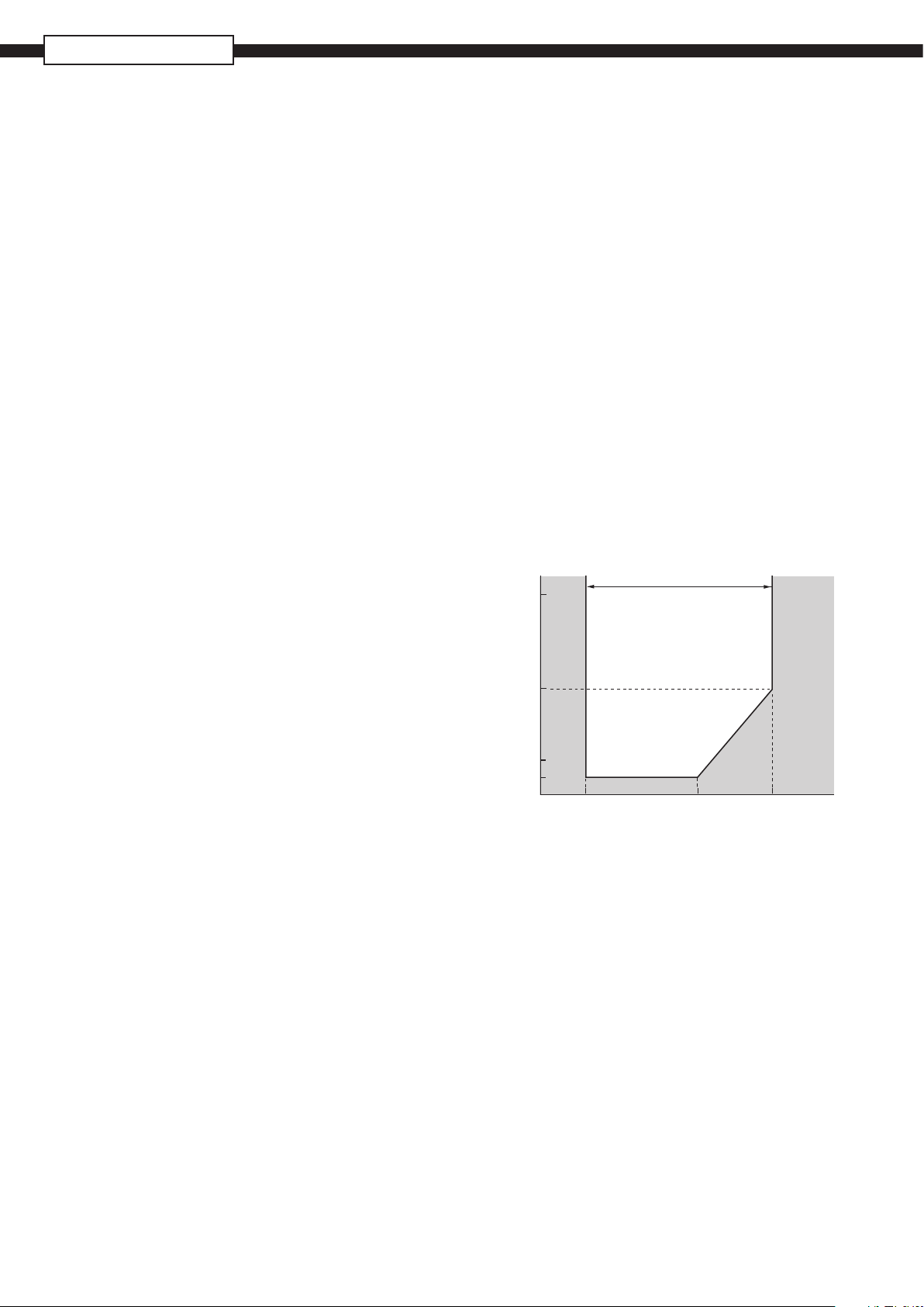
FKB & FKD
[Torr]
Operating pressure
Process temperature[°C ]
PHYSICAL SPECIFICATIONS
Conduit connections :
1/2”-14 NPT, Pg13.5 or M20x1.5
Process-wetted parts material :
Diaphragm :
SS 316L, Hastelloy-C, Monel, Tantalum, Titanium or
Zirconium
Flange face :
SS 316L, Hastelloy-C, Monel, Tantalum, Titanium or
Zirconium
Extension :
SS 316L, Hastelloy-C (refer to “Model code”)
Non-wetted parts material :
Electronics housing :
Low copper die-cast aluminum alloy nished with
polyester coating (standard), or SS 316 (option).
Bolts and nuts :
Standard :
Cr-Mo alloy
Option :
SS 316 (L) for pressure ≤ 100 bar or
SS 660 for pressure > 100 bar
Filling uid :
Standard :
Silicone oil
Option :
Fluorinated oil
Mounting bracket :
SS 304L or SS 316L
Environmental protection :
IEC IP66/IP67 and Type 4X
Mounting bracket:
Without : direct mounting
With (option) : On 50 mm (2”) pipe or direct wall mounting
Mass {weight} :
Refer to outline dimensions page 12 to 17.
Diaphragm seal(s) :
A comprehensive selection of seals can be chosen in ac-
cordance with the specic seal (see datasheet).
OPTIONAL FEATURES
Local indicator :
A plug-in analog indicator (2.5% accuracy) can be
mounted into the electronics compartment or the
terminal box of the housing.
An optional 5 digit indicator with engineering units is also
available.
Localcongurationwiththe3push-buttonsindicator:
A local conguration can be carried out with the optional 3
push-buttons 5-digits indicator.
Arrester :
A built-in arrester protects the electronics from lightning
surges.
Lightning surge immunity :
±4 kV (1.2 × 50 µs)
NACEspecication:
Metallic materials for all pressure boundary parts com-
ply with NACE MR 0175/ISO 15156.
SS 660 bolts and nuts comply with NACE MR 0175/ISO
15156.
Optional tag plate :
An extra stainless steel tag plate for customer tag data is
wired to the transmitter.
Vacuum service : See Fig.1
Special silicone oil and lling procedure are applied.
760
Sealing liquid:Silicone oil (Code Y)
Operating area
150
30
20
type only
Non
operating
area
ACCESSORIES
Hand held communicator :
FXW model, refer to datasheet No.EDS 8-47
120–40 –15 60
Fig. 1
Relation between process temperature and operating
pressure
4
Page 5

MODEL CODE SYMBOLS - FKB
1 2 3 4 5 6 7 8 9 10 11 12 13
K
F B V F - Y
Notes* :
1- Turn down ratio of 100 is possible but span greater than 1/40 of the the URL is rec-
ommended for better performances.
2- For DN<50, please consult Fuji Electric regarding the process conditions
3- The ange rating is according to the Maximum Working Pressure. For PN > 150 bar,
please consult Fuji Electric
4- For capillary version, the standard mounting bracket is provided. No mounting
bracket with rigid mounting version.
5- Except digit 10 = “P”, “Q”
6- Standard cell lling uid = silicone oil. Other lling uids upon request.
7- Only with digit 4 = “T”, “W”, “6”, “8”
8- SS 660 bolts/nuts are in conformity with NACE MR0175/ISO 15156
9- SS 316L enclosure not available for “T” shape version
10- For rigid assembling, bolts and nuts are required. Please specify bolts and nuts ma-
terial (digit 12), even if P < 50bar
T
V
W
5
6
7
8
2
4
6
8
9
L
M
N
P
1 (*2)
2
3 0.3 to 30 bar
4 1 to 100 bar
5 5 to 500 bar
V F - A
V F - B Analog, 0-100% linear scale
V F - D Analog, Custom scale
V F - J
V F - E None
V F - F Analog, 0-100% linear scale
V F - H
V F - K Analog, double scale
V F - L Digital, 0-100%
V F - P
V F - Q Digital, 0-100%
V F - S Digital, Custom scale
V F - 1 Digital, 0-100% with push button
V F - 2
V F - 4 Digital, 0-100% with push button
V F - 5
A
X
K
P
M
E
J
L
R
T
Q
N
W
B Capillary
L Rigid - Long design (in line)
M Rigid - Short design (90°)
G Capillary
S
T
1 Y
2 Y
3 Y None
(*9)
4 Y Yes
(*9)
Y Y None
B Y Yes
C Y
E Y Yes
A Y None
D Y Yes
F Y
G Y Yes
H Y (*8) None
J Y (*8) Yes
K Y (*8)(*9)
L Y (*8) Yes
Type
Gauge pressure transmitter with remote seal - Smart, 4-20 mA + HART/Fuji Electric communication protocol
Conduit connection Enclosure type
1/2 - 14 NPT
Pg13.5 “L” shape
M20 x 1.5
G 1/2
1/2 - 14 NPT
Pg13.5
M20 x 1.5
(*3)
Diaphragm seal rating
PN 25
PN 20 - 150 lbs
PN 50 - 300 lbs
PN 40
PN 16
PN 100 - 600 lbs
PN 150 - 900 lbs
PN 250 - 1500 lbs
PN 420 - 2500 lbs
Measuring range
(*1)
0.013 to 1.3 bar
0.05 to 5 bar
(*2)
(*3)
Indicator Arrester
None
(*5)
(*5)
Analog, double scale
(*5)
(*5)
Analog, Custom scale
(*5)
(*5)
Digital, Custom scale
Digital, Custom scale with push button
Digital, Custom scale with push button
Hazardous location approvals
None
ATEX - Flameproof
(*7)
ATEX - Intrinsic Safety
ATEX - Increased Safety
ATEX - Combination Flameproof and Intrinsic Safety
(*7)
cCSAus - Explosion proof
(*7)
cCSAus - Intrinsic Safety and Non Incendive
cCSAus -Combination Explosion proof, Intrinsic Safety and Non Incendive
(*7)
IECEx - Flameproof
(*7)
IECEx - Intrinsic Safety
IECEx - Increased Safety
(*7)
IECEx - Combination Flameproof and Intrinsic Safety
(*7)
IECEx - ATEX - cCSAus - Explosion/Flameproof, Intrinsic Safety and Non Incendive
(*4)
(*10)
(*10)
(*10)
(*10)
(*6)
(*10)
(*10)
(*10)
(*10)
(*9)
(*9)
(*9)
(*9)
Mounting design
Rigid - Long design (in line)
Rigid - Short design (90°)
Cell flange design Stainless steel parts
Operating pressure
p ≤ 50 bar
50 < p ≤ 100
p ≤ 100 bar
p = 100 bar max
(*9)
“T” shape
Bolts/nuts Tag plate Housing
None
Carbon steel
SS 316(L) / SS 316(L)
SS 660/SS 660 None
DESCRIPTION
None
Yes
None
Yes
None
Yes
Ambiant temperature correction
Transmitter and diaphragm seal assembly
Transmitter
None
Yes
None
None
None
Yes
None
Yes
None
Yes
None
Yes
5
Page 6
FKB, FKD, FKM...F
1 2 3 4 5 6 7 8 9 10 11 12 13
MODEL CODE SYMBOLS - FKD
F K D
T 1/2 - 14 NPT
V Pg13.5
W M20 x 1.5
5
6
7
8
Notes* :
1- Turn down ration of 100 is possible but span greater than 1/40 of the the URL is recommended for
better performances.
2- For DN<50, please consult Fuji Electric regarding the process conditions
3- For capillary version, the standard mounting bracket is provided. No mounting bracket with rigid
mounting version.
4- Except Digit 10 = "P", "Q"
5- Standard cell lling uid = silicone oil. Other lling uids upon request.
6- Temperature correction must be done when diaphragm seals or capillarity lengths are different be-
tween HP and LP
7- Only with Digit 4 = "T", "W", "6", "8"
8- SS 660 bolts/nuts are in conformity with NACE MR0175/ISO 15156
9- High static pressure cell is mandatory.
10- SS 316L enclosure not available for "T" shape version
11- The ange rating is according to the Maximum Working Pressure
12- For rigid assembling, bolts and nuts are required. Please specify bolts and nuts material (digit 12),
even if P < 50 bar
V F - Y
2 PN 25
4 PN 20 - 150 lbs
6 PN 50 - 300 lbs
8 PN 40
9 PN 16
L PN 100 - 600 lbs
M PN 150 - 900 lbs
N PN 250 - 1500 lbs
P PN 420 - 2500 lbs
3 (*2) 3,2 to 320 mbar
5 (*2) 0,013 to 1,3 bar
6 0,05 to 5 bar
8 0,3 to 30 bar
9 2 to 200 bar
V F - A None
V F - B
V F - C
V F - D
V F - J
V F - E
V F - F
V F - G
V F - H
V F - K
V F - L
V F - M
V F - P
V F - Q
V F - N
V F - S
V F - 1
V F - 2
V F - 3
V F - 4
V - 6
6
Type
Differential pressure transmitter with remote seals - Smart, 4-20 mA + HART/Fuji Electric communication protocol
Conduit connection
G 1/2
1/2 - 14 NPT
Pg13.5
M20 x 1.5
(*11)
Diaphragm seal rating
(*9)
(*9)
Measuring range
(*1)
Indicator Arrester
(*4)
Analog, 0-100% linear scale
(*4)
Analog, 0-100% √
Analog, Custom scale
(*4)
Analog, double scale
(*4)
None
Analog, 0-100% linear scale
(*4)
(*4)
Analog, 0-100% √
(*4)
Analog, Custom scale
Analog, double scale
(*4)
Digital, 0-100%
Digital, 0-100% √
Digital, Custom scale
Digital, 0-100%
Digital, 0-100% √
Digital, Custom scale
Digital, 0-100% with push buttons
Digital, Custom scale with push buttons
Digital, 0-100% √ with push buttons
Digital, 0-100% with push buttons
Digital, Custom scale with push buttons
Digital, 0-100% √ with push buttons
Hazardous location approvals
A
X
K
P
M
E
J
L
R
T
Q
N
W
B
C
E
G
H
1 Y
2 Y
3 Y
4 Y Yes
Y Y None
B Y Yes
C Y
E Y Yes
A Y None
D Y Yes
F Y None
G Y Yes
H Y (*8) None
J Y (*8) Yes
K Y (*8) (*10)
L Y (*8) Yes
None
ATEX - Flameproof
(*7)
ATEX - Intrinsic Safety
ATEX - Increased Safety
ATEX - Combination Flameproof and Intrinsic Safety
(*7)
cCSAus - Explosion proof
(*7)
cCSAus - Intrinsic Safety and Non Incendive
(*7)
cCSAus -Combination Explosion proof, Intrinsic Safety and Non Incendive
IECEx - Flameproof
(*7)
IECEx - Intrinsic Safety
IECEx - Increased Safety
IECEx - Combination Flameproof and Intrinsic Safety
(*7)
(*7)
IECEx - ATEX - cCSAus - Explosion/flameproof, Intrinsic Safety and Non Incendive
(*3) (*6)
Capillary on HP & LP side
Rigid short design on HP, capillary on LP side
Capillary on HP & LP side
Cell flange design Stainless steel parts
Operating pressure
p ≤ 50 bar
50 < p ≤ 100
p ≤ 100 bar
(*10)
(*10)
(*12)
(*5)
(*12)
(*12)
(*12)
(*12)
(*10)
(*10)
(*10)
(*10)
p = 100 bar max
(*10)
Enclosure type
“L” shape
“T” shape
Mounting design Ambiant temperature correction
Capillary on HP side
Capillary on HP side
Bolts/nuts Tag plate
None
Carbon steel
SS 316(L) / SS 316(L)
SS 660/SS 660
DESCRIPTION
None
Yes
None
Yes
None
YesV FF - 5
Transmitter and diaphragm seal assembly
Transmitter
Housing
None
Yes
None
None
None
None
Yes
None
Yes
None
Yes
None
Yes
Page 7

MODEL CODE SYMBOLS - FKM
1 2 3 4 5 6 7 8 9 10 11 12 13
F K M
T 1/2 - 14 NPT
V Pg13.5 “L” shape
W
5
6
7
8
Notes* :
1- Turn down ration of 100 is possible but span greater than 1/40 of the the URL is
recommended for better performances.
2- Please consult Fuji Electric regarding the process conditions
3- For capillary version, the standard mounting bracket is provided. No mounting
bracket with rigid mounting version.
4- Except Digit 10 = "P", "Q"
5- Standard cell lling uid = silicone oil. Other lling uids upon request.
6- Only with Digit 4 = "T", "W", "6", "8"
7- SS 660 bolts/nuts are in conformity with NACE MR0175/ISO 15156
8- SS 316L enclosure not available for "T" shape version
9- The ange rating is according to the Maximum Working Pressure
10- For rigid assembling, bolts and nuts are required. Please specify bolts and nuts
material (digit 12), even if P < 50bar
V F - Y DESCRIPTION
2 PN 25
4 PN 20 - 150 lbs
6 PN 50 - 300 lbs
8 PN 40
9 PN 16
1 (*2) 0.016 to 0.16 bar abs
2 (*2) 0.013 to 1.3 bar abs
3 0.05 to 5 bar abs
4 0.3 to 30 bar abs
5 1 to 100 bar abs
V F - A None
V F - B Analog, 0-100% linear scale
V F - D Analog, Custom scale
V F - J Analog, double scale
V F - E None
V F - F Analog, 0-100% linear scale
V F - H Analog, Custom scale
V F - K Analog, double scale
V F - L Digital, 0-100%
V F - P Digital, Custom scale
V F - Q Digital, 0-100%
V F - S Digital, Custom scale
V F - 1 Digital, 0-100% with push buttons
V F - 2 Digital, Custom scale with push buttons
V F - 4 Digital, 0-100% with push buttons
V F - 5 Digital, Custom scale with push buttons
A
X
K
P
M
E
J
L
R
T
Q
N
W
B Capillary
L Rigid - Long design (in line)
M Rigid - Short design (90°)
G Capillary
S
T
1 Y
2 Y
3 Y
4 Y
Y Y
B Y
C Y
E Y
A Y
D Y
F Y
G Y
H Y (*7)
J Y (*7)
K Y (*7)(*8)
L Y (*7)
Type
Absolute pressure transmitter with remote seal - Smart, 4-20 mA + HART/Fuji Electric communication protocol
Conduit connection Enclosure type
M20 x 1.5
G 1/2
1/2 - 14 NPT
Pg13.5
M20 x 1.5
(*9)
Diaphragm seal rating
Measuring range
(*1)
Indicator
(*4)
(*4)
(*4)
(*4)
(*4)
(*4)
Hazardous location approvals
None
(*6)
ATEX - Flameproof
ATEX - Intrinsic Safety
ATEX - Increased Safety
(*6)
ATEX - Combination Flameproof and Intrinsic Safety
cCSAus - Explosion proof
(*6)
cCSAus - Intrinsic Safety and Non Incendive
cCSAus -Combination Explosion proof, Intrinsic Safety and Non Incendive
(*6)
IECEx - Flameproof
(*6)
IECEx - Intrinsic Safety
IECEx - Increased Safety
(*6)
IECEx - Combination Flameproof and Intrinsic Safety
IECEx - ATEX - cCSAus - Explosion/flameproof, Intrinsic Safety and Non Incendive
(*6)
(*8)
(*8)
(*3)
(*10)
(*10)
(*10)
(*10)
(*5)
(*10)
(*10)
(*10)
(*10)
(*8)
(*8)
(*8)
(*8)
Operating pressure
Mounting design
Rigid - Long design (in line)
Rigid - Short design (90°)
p ≤ 50 bar
50 < p ≤ 100
p ≤ 100 bar
p = 100 bar max
(*8)
“T” shape
Ambiant temperature correction
Transmitter and diaphragm seal assembly
Bolts/nuts Tag plate
None
Carbon steel
SS 316(L) / SS 316(L)
SS 660 / SS 660
Arrester
None
Yes
None
Yes
None
Yes
Stainless steel partsCell flange design
None
Yes
None
Yes
None
Yes
None
Yes
None
Yes
None
Yes
None
Yes
None
Yes
Transmitter
Housing
None
Yes
None
Yes
None
Yes
None
Yes
7
Page 8

FKB, FKD, FKM...F
SEAL DIAPHRAGMS
Fuji Electric seal diaphragms are dedicated to accurately
measurelevelanddensityonopenandclosedtanks,ow
and line pressure in pipes in heavy process conditions.
The use of remote seal diaphragms avoids the measuring
cell to be directly in contact with the process conditions.
The various diaphragm architectures and the welded seal
construction provide to the Fuji Electric remote seal diaphragm offer an excellent reliability in harsh processing
conditions such as high static pressure, temperature or
corrosiveness as weel as viscous, crystallizable or abrasive
process.
S
FEATURES
1- Construction
Connection of the remote seal to the measuring cell diaphragms
can be done either by a rigid (direct) or capillary architectures.
The full welded Fuji Electric design allows a free of gasket path
between the remote seal and the differential, gauge or absolute
measuring cell of the FCX-AII V5 pressure transmitters.
Depending the nature of the process, specic lling uids are
available to ensure the optimal transmission of the process
pressure to the measuring cell.
2- Operating principle
The pressure is applied on the remote seal and transferred by
the lling uid through the capillary path to the measuring cell
of the pressure transmitter.
3- Wide variety of materials selection
Depending the process conditions, wetted or non-wetted parts and
lling uids can be selected thanks to the model code denition.
Wetted parts :
AISI 316L, Tantalum, Hastelloy, Monel, Titanum, Zirconium,
AISI 316L with Gold or PFA coating.
Non wetted parts :
AISI 316L
Filling uids :
Standard silicone, uorinated, alimentary, high temperature,
and vacuum specic oils.
For specic process conditions, please consult Fuji Electric.
4- Diaphragm seal types
According to the mounting and operating conditions different
seal types can be useful :
Flush mounting design from DN40 to DN100.
Seals with extensions (50 to 200 mm).
Flanged, screwed or welded neck adapters
Seals for sanitary applications according DIN, SMS or Tri-
Clamp standards.
For specics seals, please consult Fuji Electric.
8
FUNCTIONAL SPECIFICATIONS
Remote seal diaphragm assembling :
The remote seal can be assembled on the transmiter either
by a direct (rigid) connection (as for level measurement
at the bottom of a tank) or by capillary (distant measuring
point, high temperature process).
The rigid assembling can be either “long design” (in line)
or “short design” (90°) as shown in the outline dimension
drawings.
Rigid mounting Capillary mounting
FKB short or long design HP side
FKM short or long design HP side
FKD Refer to FKR level HP and LP side
transmitter technical HP side
datasheet LP side
Capillarytubespecications:
Standard capillary lengthes :
1.5 / 3 / 6 m (other upon request)
Inside diameter :
1 mm standard
2 mm for vacuum service, high process temperature
applications, short response time requirements
Smallest bending radius of the capillary : 100 mm
Capillary tube shealding possibilities :
Temperature limit :
PVC sleeve :
-10 to 80°C
Stainless steel sheald :
-40 to 350°C
Process connection possibilities :
The remote seal diaphragms can be :
- For ush mounting
- With extension
- With mounting adapters mounting (anged, screwed or
welded neck).
The mounting adapter is dedicated to either adapt the
remote seal to a specic process connection or increase the
sensibilty of the transmitter with special process conditions.
Page 9

Temperature limits :
Ambiant temperature :
-40 to 85°C for transmitter
Process temperature :
-40 to 150°C for rigid mounting, 0 to 350°C for capillary
design, and high temperature lling uid.
Pressure limits :
Working pressure :
Limited by by the smallest value between the nominal ange
rating of the seal diaphragm and the maximum working
pressure of the transmitter.
Vacuum limit :
Depends on the limit of the measuring cell and the lling uid
of the remote seal. For the differential or gauge pressure
transmitter, the vacuum limit is 20 Torr or 27 mbar abs.
Only the absolute pressure transmitter can be used till
absolute zero (FKM).
For process pressure < 20 Torr, please consult Fuji Electric.
PERFORMANCE SPECIFICATIONS
To evaluate the global performances, both the transmitter and the
remote seal diaphragm performances must be considered under
the reference conditions : standard silicone oil lling, SS 316L
seal diaphragm, 4-20 mA output in linear mode.
Process temperature effect :
Transmitters
FKB/FKM FKD
Seals Gauge/absolute pressure differential pressure
DN50 / 2” 1.24 0.5
SS 316L diaphragm
DN80 / 3” 0.17 0.09
SS 316L diaphragm
DN80 / 3” other 0.73 0.22
diaphragm materials
DN100 / 4” 0.08 0.05
SS 316L diaphragm
Adaptor 0.17 0.09
SS 316L diaphragm
Effect (mbar/10°C)
Staticpressureeffectfor∆Ptransmitterwithstainlesssteel
diaphragms (FKD transmitter with DN80 and DN100 seals) :
Zero shift :
± 0,2% of URL for ange rating, up to 40 bar or 300 lbs
Response time : (mean values)
Oil lling Code Response time
digit 7 0 to 0 to
320 mbar 1.3 bar
Std silicone oil Y, G 0.15 0.037
Fluorinated oil W,A,D 0.17 0.04
Oil for vaccum or U, X 0.25 0.065
high temperature
The indicated values are in seconds per meter of capillary
length with internal tube diameter Ø 1 mm.
The indicated response time is based on a pressure change
of 0 to 100% of the calibrated span at reference temperature
of 20°C.
The indicated values do not include the response time of
the transmitter.
Accuracy :
Assembling 1 or 2 remote seal diaphragms on a transmit-
ter increases the accuracy error at reference conditions
by 0,1% of the span.
Ambiant temperature effect :
Effect when only transmitter is corrected.
(See digit 11 code G, S, T of the FKB and FKM model codes
and code G, H of the FKD model code).
Transmitters
FKB/FKM Capillary FKD Capillary
Seals Gauge / Abs. (m) Differential (m)
pressure pressure
DN 50 / 2” - 2.03 1.5 0.48 0.32
SS 316L diaphragm
DN 80 / 3” - 0.11 0.08 0.04 0.03
SS 316L diaphragm
DN80 / 3” - other 0.22 0.2 0.05 0.07
diaphragm materials
DN100 / 4” - 0.04 0.03 0.02 0.01
SS 316L diaphragm
Adaptor - 0.11 0.08 0.04 0.03
SS 316L diaphragm
Effect (mbar/10°C)
Note : the indicated values are in mbar/10°C for capillary
length of 1m and internal capillary tube ø of 1 mm
Effect when both the transmitter and the seal assembly
are corrected. (See codes B,C,L,M digit 11 of the FKB,
FKD and FKM model codes).
Fillinguidofthediaphragmseals:
Code Designation Temperature resistance (°C) Density
digit 7 P abs ≥ 1 bar P abs < 1 bar (25°C)
Y Silicone oil -40 to 180 -40 to 120 0.95
W Fluorinated oil -20 to 200 -20 to 120 1.84
F Sanitary ll uide -10 to 250 -10 to 120 0.94
V Silicone oil 20 to 200 1.07
U Silicone oil 0 to 300 20 to 200 1.07
X Silicone oil -10 to 350 20 to 200 1.09
The indicated values and limits are indicated for the most
common applications (standard lling uids).
Please consult Fuji Electric for special applications indicating
your temperature, pressure and vacuum conditions (vacuum
and temperature can occure together).
Other lling uids can be used for your applications.
The correction of the zero drift can be done at factory level
on the complete system (transmitter and remote seals)
by an additional temperature correction operation..
A thermal isolation or a heating of the capillaries minimises
the ambient temperature effect.
9
Page 10

FKB, FKD, FKM...F
1 2 3 4 5 6 7 8
S
MODEL CODE SYMBOLS - S
* Notes :
1- Standard seal land surface nishing (stock nish). Other nishing (recess,
groove…) : please consult Fuji Electric.
For material codes H, B, T, P, R, F : smooth nishing
2- Only available for P > 1 bar. Please consult Fuji Electric regarding the process
conditions
3- Only for axial seal diaphragm connection - No extension possible
4- SS 316L for DN50, 80, 100 and ange adapter
5- Not possible with digit 7 = “V”, “U” and “X”
6- All wetted parts in the same material (diaphragm, extension and seal land
surface). Available for digit 3 = 4, 5, 6, 7, 8, 9, H, J, G - Other remote seal on
demand
7- Vacuum service and high temperature > 120 °C : internal capillary diameter =
2mm
8- Please consult Fuji Electric regarding the process conditions (minimum pres-
sure, maximum temperature)
9- Maximum process temperature : 150°C
10- When no code can be found in the current model code, place “*” in the corre-
sponding digit code as well as in the 16th digit
11- Only for FKP, FKH and rigid assembly. P > 1.3 bar
S
A Axial
R
W
-
4 ANSI-150 Lbs 3'' / ISO PN20 DN80
5 ANSI-150 Lbs 4'' / ISO PN20 DN100
6 ANSI-300 lLbs 3" / ISO PN50 DN80
7 ANSI-300 Lbs 4" / ISO PN50 DN100
8 DIN PN40 DN80
9 DIN PN16 DN100
H (*2) ANSI-150 lbs 2'' / ISO PN20 DN50
J (*2) ANSI-300 lbs 2'' / ISO PN50 DN50
G
K
L
U PN25 DN50 - coupling nuts DIN 11851 Digit 4 = "V" only
V PN40 DN50 - coupling nuts SMS Digit 4 = "V" only
W PN40 DN50 - seal only Clamp Digit 4 = "V" only
X No dead volume Sanitary Digit 4 = "V" only
A (*3) Flange adapter PN40 DN25 Digit 4 = "V" only - others upon request
B (*3)
C (*3)
D (*3)
E (*3)
F (*3)
S (*3)
T (*3) To be welded (2"1/2 pipe) Digit 4 = "V" only - others upon request
V SS 316L SS 316L
H
B
T
P
R
C
F
Y Flush mounting
A Diaphragm extension 50 mm
B Diaphragm extension 100 mm Digit 4 = "V"
C Diaphragm extension 150 mm
D Diaphragm extension 200 mm
E Diaphragm extension 50 mm
F Diaphragm extension 100 mm
G Diaphragm extension 150 mm
H Diaphragm extension 200 mm
J Diaphragm extension 50 mm
K Diaphragm extension 100 mm
L Diaphragm extension 150 mm
M Diaphragm extension 200 mm
P Diaphragm extension 50 mm
R
S
T Diaphragm extension 200 mm
A
B
C
D
G (*7)
H
K
L
R
R
Y None (standard) Silicone oil
W None (standard) Fluorinated oil
F None (standard) Sanitary fill fluid
D Chlorine service Fluorinated oil
G Degreasing Silicone oil
A Oxygen service Fluorinated oil - Digit 4 = ''V'' only
N NACE MR 0175 / ISO 15156 Silicone oil
V (*8)
U
X
- * (*10)
Remote seal diaphragms
Flange / Capillary connection
Radial - Not possible with rigid assembling design (digit 6 = "R")
Wafer type - Not possible with rigid assembling design (digit 6 ="R")
(*1) Flanges RF (flange size and rating)
(*2)
DIN PN40 DN50
(*11)
G 2" screwed seal
G 1 1/2" screwed seal
(*11)
Flange adapter ISO PN20 DN25 (1"-150 ANSI) Digit 4 = "V" only - others upon request
Flange adapter ISO PN50 DN25 (1"- 300 ANSI) Digit 4 = "V" only - others upon request
Flange adapter PN40 DN40 Digit 4 = "V" only - others upon request
Flange adapter ISO PN20 DN40 (1"1/2 - 150 ANSI) Digit 4 = "V" only - others upon request
Flange adapter ISO PN50 DN40 (1"1/2 - 300 ANSI) Digit 4 = "V" only - others upon request
Screwed 1/2 NPTE Digit 4 = "V" only - others upon request
Diaphragm Seal land surface Flange
(*4)
Hastelloy-C Hastelloy-C
Tantalum Tantalum SS 316L
(*9)
(*9)
(*5)
(*6)
(*6)
(*6)
(*6)
(*6)
(*6)
(*6)
(*6)
(*6)
(*6)
(*6)
(*6)
(*6)
(*6)
(*6)
(*6)
(*7)
(*7)
(*7)
(*8)
(*8)
Zirconium Zirconium
SS 316L + gold coating SS 316L
SS 316L + PFA lining SS 316L + PFA lining
Seal diaphragm design
Diaphragm extension 100 mm
Diaphragm extension 150 mm
Remote seal assembling characteristics
Mounting assembly Length Protection
Capillary
Rigid assembly for FKB, FKD & FKM - Not possible with digit 2 = "R", "W" - Maximum process temperature: 150 °C
Rigid assembly for FKP & FKH - Not possible with digit 2 = "R", "W" - Maximum process temperature: 150 °C
Specific applications and filling fluids for the remote seal
Treatment Filling fluids
Vacuum service - maximum T° 200°C Silicone oil
Very high temperature (0 to 300°C) - No vacuum
Very high temperature (20 to 350°C) - No vacuum
Special options
Special, no code available
Seal diaphragm design
Monel Monel
Titanium Titanium
1,5 m
3 m
6 m
Upon request
1,5 m
3 m
6 m
Upon request
DESCRIPTION
Digit 4 = "V"
Digit 4 = "V"
Digit 4 = "V"
Digit 4 = "H"
Digit 4 = "H"
Digit 4 = "H"
Digit 4 = "H"
Digit 4 = "B"
Digit 4 = "B"
Digit 4 = "B"
Digit 4 = "B"
Digit 4 = "T"
Digit 4 = "T"
Digit 4 = "T"
Digit 4 = "T"
PVC
sleeve
Stainless
steel
sleeve
10
Page 11

ELECTROMAGNETIC COMPATIBILITY
All FCX-AII series of pressure transmitters are in conformity with the provision of the EMC Directive 2014/30/EU on the
harmonization of the laws of the Members States relating to electromagnetic compatibility.
All these models of pressure transmitters are in accordance with the following harmonized standards :
• EN 61326-1 (Electrical equipment for measurement, control and laboratory use - EMC requirements -
Part 1: General requirements).
• EN 61326-2-3 (Particular requirements - Test conguration, operational conditions and performance criteria for tranducers
with integrated or remote signal conditioning).
Emission limits (according to EN 55011 / CISPR 11, Group 1 Class A)
Frequency range (MHz) Limits Result
30 to 230 40 dB (µV/m) quasi peack, measured at 10 m distance Passed
230 to 1000 47 dB (µV/m) quasi peack, measured at 10 m distance
Immunity
Phenomenon Test value Standard Required Result
Performance criteria of criteria
Electrostatic Discharge ±4 kV (Contact) EN/IEC 61000-4-2 B A
±8 kV (Air)
Radiated, Electromagnetic 10 V/m (0.08 to 1.0 GHz) EN/IEC 61000-4-3 A A
Field 3 V/m (1.4 to 2.0 GHz)
1 V/m (2.0 to 2.7 GHz)
Fast transients (burst) 2 kV (5/50 ns, 5 kHz EN/IEC 61000-4-4 B A
Surge Transients 1 kV Line to line EN/IEC 61000-4-5 B A
2 kV Line to ground
Conducted RF Disturbances 3 Vrms (150 kHz to 80 MHz) EN/IEC 61000-4-6 A A
80% AM @ 1 kHz
Power Frequency 30 A/m (50 Hz, 60 Hz) EN/IEC 61000-4-8 A A
Magnetic Field
Performance criteria (A & B): according to IEC 61326
11
Page 12

FKB, FKD, FKM...F
Outline dimensiOns fOr rigid mOunted diaphragm seal On a gauge Or an absOlute pressure
transmitter
(units : mm) - Dimensions of seals - Refer to page 18 and 19
Short mounting design
WITH DIGITAL INDICATORWITH ANALOG INDICATOR
ZERO/SPAN ADJUSTMENT
G
F
E
CONDUIT CONNECTION
T
W
WEIGHT :
RANSMITTER ONLY : - 4 KG (WITHOUT OPTION)
T
A
DD : - FLANGES WEIGHT (SEE TABLE)
- 0,3
- 2 KG FOR STAINLESS STEEL HOUSING OPTION
KG FOR INDICATOR OPTION
S
TROUS /
P
R
S
l
12
Seal diaphragm
S A R
Page 13

Long mounting design
ZERO/SPAN ADJUSTMENT
WITH ANALOG INDICATOR
WITH DIGITAL INDICATOR
CONDUIT CONNECTION
T
W
F
G
S
R
P
l
WEIGHT :
RANSMITTER ONLY : - 4 KG (WITHOUT OPTION)
T
A
DD : - FLANGES WEIGHT (SEE TABLE)
- 0,3
- 2 KG FOR STAINLESS STEEL HOUSING OPTION
KG FOR INDICATOR OPTION
S
E
Seal diaphragm :
S A
13
Page 14

FKB, FKD, FKM...F
Outline dimensiOns fOr capillary mOunted diaphragm seal(s) On a differential pressure
transmitter
ForPN≤50bar:reducedvolumeangesareweldedonthemeasuringcell
(units : mm) - Dimensions of seals - Refer to page 18 and 19
WITH ANALOG INDICATOR
WITH DIGITAL INDICATOR
Z
ERO/SPAN
Code X4
T
W
CONDUIT CONNECTION
ADJUSTMENT
F
S
R
P
S
Seal
diaphragm
G
WEIGHT :
RANSMITTER ONLY : - 3.5 KG (WITHOUT OPTION)
T
A
DD : - FLANGES WEIGHT (SEE TABLE)
- 1
- 0.3 KG FOR INDICATOR OPTION
- 2 KG FOR STAINLESS STEEL HOUSING OPTION
KG PER 50 MM EXTENSION
Seal
diaphragms
MOUNTING BRACKET FOR
2” PIPE (Ø50 MM)
E
14
S A
SEAL DIAPHRAGMS
S A
Page 15

ForPN>50bar:reducedvolumeangesareweldedandboltedonthemeasuringcell
WITH ANALOG INDICATOR
WITH DIGITAL INDICATOR
Z
ERO/SPAN
ADJUSTMENT
CONDUIT CONNECTION
T
W
S
WEIGHT :
RANSMITTER ONLY : - 3.5 KG (WITHOUT OPTION)
T
A
DD : - FLANGES WEIGHT (SEE TABLE)
- 1
- 0.3 KG FOR INDICATOR OPTION
- 2 KG FOR STAINLESS STEEL HOUSING OPTION
KG PER 50 MM EXTENSION
S
R
P
MOUNTING BRACKET FOR
2” PIPE (Ø50 MM)
EAL
S
DIAPHRAGMS
F
G
E
Seal
diaphragms
SEAL DIAPHRAGMS
S AS A
15
Page 16

FKB, FKD, FKM...F
Outline dimensiOns fOr capillary mOunted diaphragm seal(s) On a gauge Or an absO-
lute pressure transmitter
ForPN≤50bar:reducedvolumeangesareweldedonthemeasuringcell
WITH ANALOG INDICATOR
WITH DIGITAL INDICATOR
(units : mm) - Dimensions of seals - Refer to page 18 and 19
Z
ERO/SPAN
ADJUSTMENT
C
ONDUIT CONNECTION
D
E
E
D
MOUNTING BRACKET FOR
G
F
2” PIPE (Ø50 MM)
WEIGHT :
RANSMITTER ONLY : - 3.5 KG (WITHOUT OPTION)
T
A
DD : - FL ANGES WEIGHT (SEE TABLE)
- 0.3
- 2 KG FOR STAINLESS STEEL HOUSING OPTION
KG FOR INDICATOR OPTION
M
16
E
Seal
diaphragms
F K M
Seal diaphragms
Seal diaphragms
FKM 0,016 bar abs 0,16 bar abs
FKM
FKM
FKM
0,013 bar abs 1,3 bar abs
0,05 bar abs 5 bar abs
4
0,3 bar abs 30 bar abs
Page 17

ForPN>50bar:reducedvolumeangesareweldedandboltedonthemeasuringcell
Seal
diaphragm
WITH DIGITAL INDICATOR
CONDUIT CONNECTION
T
W
WITH ANALOG INDICATOR
ERO/SPAN
Z
ADJUSTMENT
F
G
MOUNTING BRACKET FOR
2” PIPE (Ø50 MM)
S
R
P
E
WEIGHT :
RANSMITTER ONLY : - 3.5 KG (WITHOUT OPTION)
T
A
DD : - FLANGES WEIGHT (SEE TABLE)
- 1
- 0.3 KG FOR INDICATOR OPTION
- 2 KG FOR STAINLESS STEEL HOUSING OPTION
KG PER 50 MM EXTENSION
Seal
diaphragms
TROUS /
Seal diaphragms
S A
S
F K M
FKM 0,016 bar abs 0,16 bar abs
FKM
FKM
FKM
FKM45
0,013 bar abs 1,3 bar abs
0,05 bar abs 5 bar abs
0,3 bar abs
1 bar abs 100 bar abs
30 bar abs
17
Page 18

FKB, FKD, FKM...F
Ø E
Outline dimensiOns Of the standard diaphragm seals - flush / extensiOn
DN 50, 80, 100
t
G
L
Ø H
Ø F
Ø D
DN ≤ 25 or 1”
FLANGE DIMENSIONS ACCORDING DIN 2501 ET B16.5
DIN / ISO ANSI
PN DN NP NW ØD ØE ØF G ØH t N x Øh
40 15 95 65 45 2 22 4 x 14
40 20 105 75 58 2 22 4 x 14
40 25 115 85 68 2 22 4 x 14
40 50 165 125 102 3 48 20 4 x 18
40 80 200 160 138 3 73 20 8 x 18
16 100 220 180 158 3 96 20 8 x 18
20 15 150 lbs 1/2” 95 60,5 35 2 22 4 x 16
20 20 150 lbs 3/4” 100 70 43 2 22 4 x 16
20 25 150 lbs 1” 110 79,5 51 2 22 4 x 16
50 15 300 lbs 1/2” 95 66,5 35 2 22 4 x 16
50 20 300 lbs 3/4” 120 82,5 43 2 22 4 x 20
50 25 300 lbs 1” 125 89 51 2 22 4 x 20
20 50 150 lbs 2” 150 120,5 92 1,6 48 20 4 x 20
20 80 150 lbs 3” 190 152,5 127 1,6 73 24 4 x 20
20 100 150 lbs 4” 230 190,5 158 1,6 96 24 8 x 20
(units : mm)
50 50 300 lbs 2” 165 127 92 1,6 48 22,5 8 x 20
50 80 300 lbs 3” 210 168,5 127 1,6 73 29 8 x 22
50 100 300 lbs 4” 255 200 158 1,6 96 32 8 x 22
Outline dimensiOns Of diaphragm seals with adaptOrs
Flange adaptor
(units : mm)
Screwed adaptor
FLANGES DIMENSIONS
DIN AINSI
ØD ØE ØF Cmin f1 A ØM
PN DN Pe DN N ØH
40 25 115 85 4 14 68 18 2 83 72,2
20 25 150 1” 108 79,5 4 15,8 50,8 16 1,6 81 72,2
50 25 300 1” 124 89 4 19 50,8 17,5 1,6 86 72,2
40 40 150 110 4 18 88 18 3 85 72,2
20 40 150 1 1/2” 127 98,4 4 15,8 73 18 16 85 72,2
50 40 300 1 1/2” 156 114,3 4 22,2 73 21 1,6 91 72,2
18
Page 19

Outline dimensiOns Of sanitary diaphragm
ø43,7
DN25 NUT
(DIN 11851)
(units : mm)
The seals for the sanitary and pharmaceutical applications are available DIN, SMS and Tri Clamp standards
Seals according DIN 11851 and SMS standard
2 different designs exist for DIN 11851 and SMS : (d
= diaphragm actif diameter)
M
Coupling nut design
Male thread design
d
M
DN
G
DIN 11851
DN PN (Max) D h dM G
25 40 63 36 25 Rd 52 x 1/6
32 40 70 36 32 Rd 58 x 1/6
40 40 78 36 40 Rd 65 x 1/6
50 40 112 36 52 Rd 78 x 1/6
65 40 112 36 65 Rd 95 x 1/6
80 40 127 36 76 Rd110 x 1/4
SMS
DN PN (Max) D h dM G
h
25 40 51 38 25 Rd 40 x 1/6
32 40 60 38 32 Rd 48 x 1/6
38 40 74 38 40 Rd 60 x 1/6
51 40 84 38 52 Rd 70 x 1/6
63.5 40 100 38 65 Rd 85 x 1/6
76 40 114 38 76 Rd 98 x 1/4
Tri Clamp design
Dead volume seal
43
53
DN PN (Max) D h d
1“1/2 40 50,5 35 32
2“ 40 64 35 40
2“1/2 40 77,5 35 50
3“ 40 91 35 65
M
ø36
ø40
Diaphragm
19
Page 20
FKB, FKD, FKM...F
Fuji Electric France S.A.S.
46 rue Georges Besse - ZI du brézet - 63039 Clermont ferrand
Tél : 04 73 98 26 98 - Fax : 04 73 98 26 99
Mail : sales.dpt@fujielectric.fr - web : www
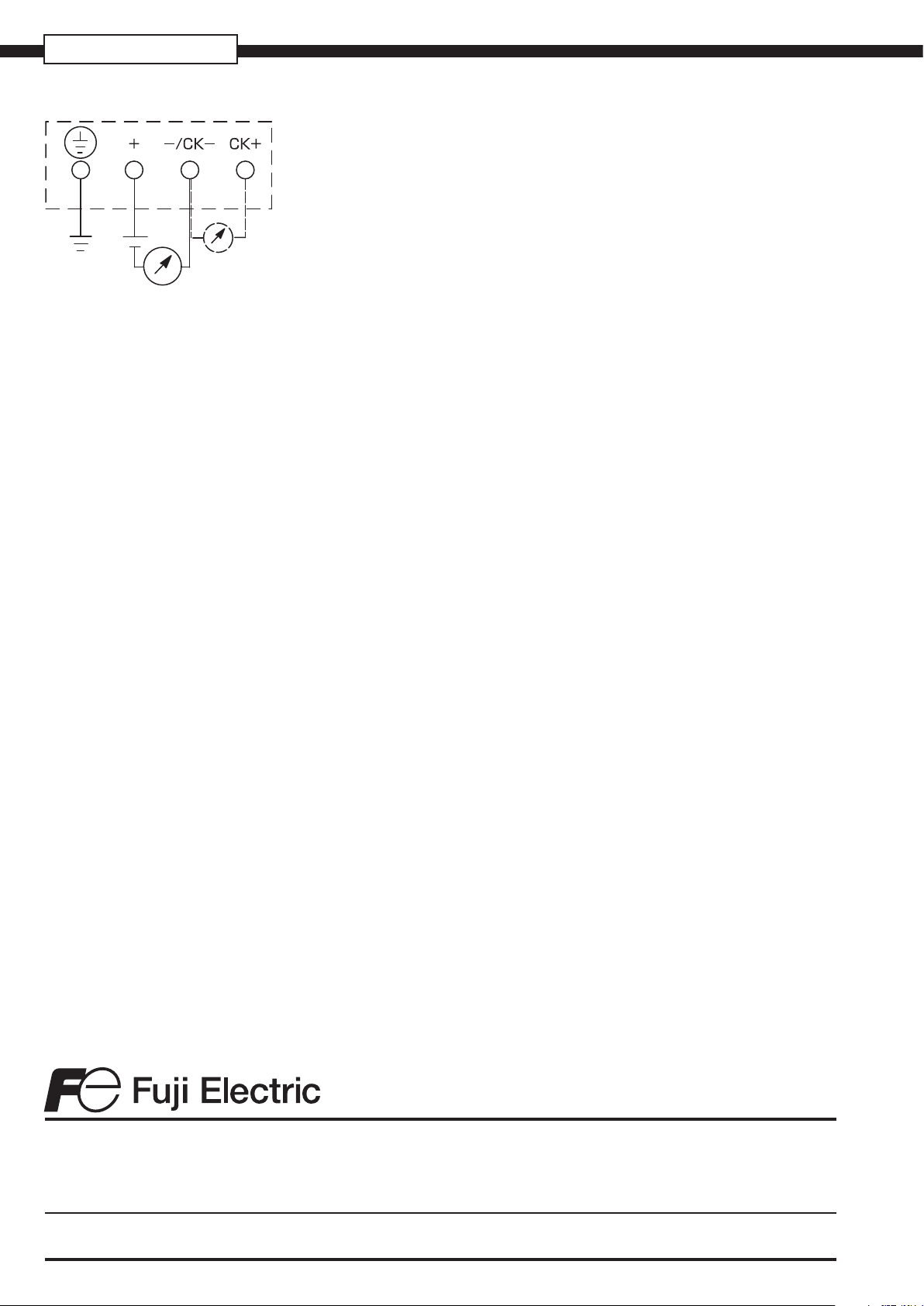
CONNECTION DIAGRAM
.fujielectric.fr
Fuji Electric can accept no responsability for possible errors in catalogues, brochures and other printed material. Fuji Electric reserves the right to alter its products without notice. This
also applies to products already on order provided that such alterations can be made without subsequential changes being necessary in specications already agreed. All trademarks
in this material are property of the respective companies. all rights reserved.
 Loading...