

Page 1

LOV Fryer Technical Information Manual
Description Page
1.1 ATO (Automatic Top-Off) Service Procedures……………………….2
1.1.1 ATO (Automatic Top-Off) Troubleshooting………………………….. 2
1.1.2 ATO (Automatic Top-Off) Board #1 Pin Positions/Harnesses……... 4
1.1.3 ATO (Automatic Top-Off) Board #2 Pin Positions/Harnesses……... 5
1.1.4 Replacing the ATO (Automatic Top-Off) Board/Transformer……... 6
1.1.5 Replacing the ATO Pump/Solenoid………………………………….. 6
1.2 MIB (Manual Interface Board) Service Procedures………………… 6
1.2.1 Manually Draining……………………………………………………… 8
1.2.2 MIB (Manual Interface Board) Troubleshooting…………………….. 8
1.2.3 MIB (Manual Interface Board) Pin Positions/Harnesses…………. ...10
1.2.4 MIB (Manual Interface Board) Display Diagnostics………………….12
1.2.5 MIB (Manual Interface Board) Auto Filtration Failure Scenarios…...14
1.2.6 Replacing an MIB Board………………………………………………. 14
1.3 AIF (Automatic Intermittent Filtration) Service Procedures………… 15
1.3.1 AIF (Automatic Intermittent Filtration) Troubleshooting…………….. 15
1.3.2 AIF (Automatic Intermittent Filtration) Board #1 Pin Positions......…16
1.3.3 AIF (Automatic Intermittent Filtration) Board #2Pin Positions………17
1.3.4 Replacing an AIF (Automatic Intermittent Filtration) Board…………18
1.3.5 Replacing an Actuator………………………………………………….. 18
1.4 M2007 Computer Filtration Service Procedures…………………….. 19
1.4.1 M2007 Computer Troubleshooting…………………………………….19
1.4.2 M2007 Useful Codes…………………………………………………… 22
1.4.3 Get Mgr Flowchart……………………………………………………… 22
1.4.4 M2007 Menu Summary Tree..………………………………………… 24
1.4.5 M2007 Pin Positions/Harnesses………………………………………. 26
1.5 Loading and Updating Software………………………………………. 27
1.5.1 Loading Software from SD card to MIB and AIF Boards…………… 27
1.5.2 Loading Software from SD card to M2007 Computer………………. 29
1.6 Tech Mode………………………………………………………………. 31
1.7 Fryer Setup Mode………………………………………………………. 32
1.8 RTI Service Issues……………………………………………………… 34
1.8.1 RTI MIB Tests…………………………………………………………… 34
1.8.2 RTI LOV Wiring…………………………………………………………. 35
1.8.3 RTI LOV Test Quick Reference……………………………………….. 36
1.9 Wiring Diagrams………………………………………………………… 37
1.9.1 LOV Electric Wiring Diagram with Thermal Sensor ……………….. 37
1.9.2 LOV Electric Wiring Diagram with RTD………………………………. 38
1.9.3 LOV Gas Wiring Diagram with Thermal Sensor…………………….. 39
1.9.4 LOV Gas Wiring Diagram with RTD………………………………….. 40
rev. 12.7.2007
DECEMBER 2007
819xxxx
Page 2
1.1 ATO (Automatic Top-off) Service Procedures
2
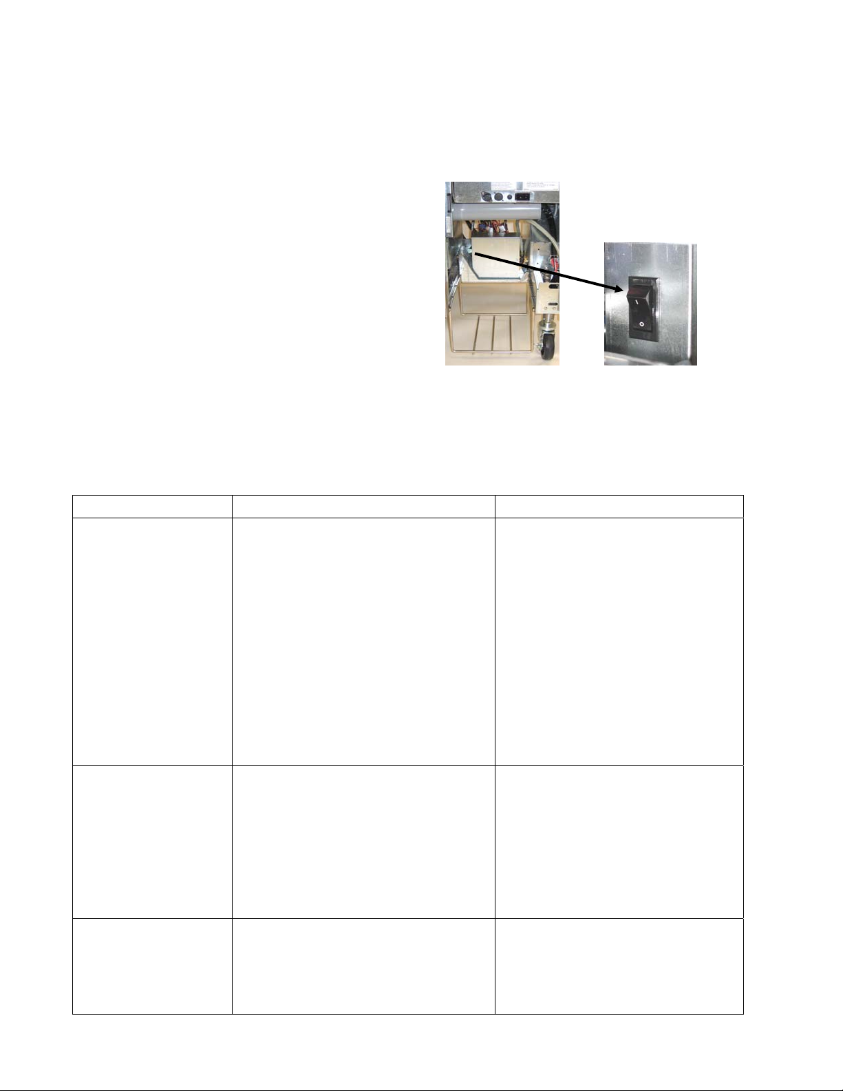
The automatic top-off system is activated when the oil level falls below a sensor in the rear of the
frypot. The signal is sent to the ATO board to engage the solenoid to the frypot and turn on the
ATO pump. The pump draws oil from the JIB (Jug In Box) to a port in the rear of the frypot.
Once the oil level has satisfied the sensor, the pump and solenoid turn off.
The ATO board is located inside the box, behind the
JIB (see Figure 1). The power for the ATO board in
electric fryers is supplied from the right hand
component box. On gas fryers the power is supplied
from the transformer box in the rear of the fryer. The
power passes through the transformer inside the ATO
box to the board. On the left side of the ATO box is
a power switch, which controls the flow of power
between the component/transformer box and the
ATO board.
Figure 1 Close up of
switch located
on the left side
of the JIB auto
top off box.
1.1.1 ATO (Automatic Top-off) Troubleshooting
Problem Probable Causes Corrective Action
A. Verify that the auto top off
power switch is switched on.
The yellow JIB low
light won’t
illuminate.
One vat tops off but
other vats fail to top
off.
Incorrect vat tops
off.
A. Auto top off power switch is off.
B. Power in the component box is
not present.
C. Failed transformer.
D. Loose wire connection
A. Failed solenoid
B. Loose wire connection.
A. Wired incorrectly.
B. Flexlines connected to wrong vat.
The switch is located behind the
JIB on the left side of the auto
top off control box.
B. Ensure power is present in the
component box.
C. If power is present in
component box, check the
transformer for correct voltage.
D. Ensure the yellow LED is
securely attached to plug J6 on
the ATO board.
A. Check power to the pump. If
the pump is hot, the solenoid
has probably failed.
B. Ensure all wiring harnesses are
securely connected to ATO
board and solenoids.
A. Ensure wires are wired
correctly.
B. Switch flexlines to correct vat.
Page 3

3
Problem Probable Causes Corrective Action
A. Verify that the auto top off
power switch is switched on.
The switch is located behind the
JIB on the left side of the auto
top off control box.
B. Check to see that fryer is
heating. Fryer temperature
must be at least 300°F (149°C).
Check probe resistance. If
probe is bad, replace the probe.
C. Ensure oil viscosity is thin
enough to pump.
D. Power to the ATO board has
been cut off. Restore power to
the board and cycle all
computers off and on to
readdress system.
E. Check solenoid to see if
functioning properly.
F. If the solenoid is working,
ensure that the screws on the
bottom of the pump are not too
tight. Loosen the screws. If
loosening the screws doesn’t fix
the problem, replace the pump.
G. Ensure transformer in ATO box
is functioning properly. Check
power from transformer to ATO
board. Ensure all harnesses are
plugged securely into place.
H. Check for proper voltages using
the pin position chart found on
page 4. If ATO found
defective, replace ATO board.
Frypots won’t top
A. Auto top off power switch is off.
B. Probe temperature lower than
setpoint.
C. Oil viscosity too thick
D. ATO board power loss
E. Failed solenoid.
off.
F. ATO pump failed or over
tightened.
G. Failed transformer/harness.
H. Failed ATO board.
Page 4
1.1.2 ATO (Automatic Top-Off) Board #1 Pin Positions (Current Prod with Thermal Sensors)
4
Connector From/To Harness # Pin # Function Voltage Wire Color
1 Output DV - Vat #1
2 Output FV - Vat #1
Solenoids
Top Off Pump
J1
J3 Transformer 8074553
J4 - Vat #3
J5 - Vat #2
J6 - Vat #1
J7 Orange LED 8074555
J8
J9
J10 AIF J5 8074546
JIB Reset Switch
Solenoids
Top Off Pump & JIB
Reset Switch
O/Flow Sensor & Fill
Sensor
Network Resistor
(pins 2 & 3)
or to next ATO Board
(4 & 5 vat units)
8074572 x1 (FV)
8074572 x2 (DV)
8074627
8074572 x1 (FV)
8074572 x2 (DV)
8074627
8074569 - Vat #1
8074567 - Vat #2
8074548 - Vat #3
8074570 - Vat #1
8074568 - Vat #2
8074549 - Vat #3
8074552
3 Output DV - Vat #2
4 Output FV - Vat #2
5 Output DV - Vat #3
6 Output FV - Vat #3
7 Top Off Pump Black
8 JIB Low Reset
9 24VAC DV - Vat #1
10 24VAC FV - Vat #1
11 24VAC DV - Vat #2
12 24VAC FV - Vat #2
13 24VAC DV - Vat #3
14 24VAC FV - Vat #3
15 Ground Red
16 Ground
1 24VAC Ret Orange
2 24VAC
3
4
5 12VAC Ret Red
6 12VAC
7
8
1 FV – SW Out Black
2 FV – Sw In White
3 DV – Sw Out Red
4 DV – Sw In
1 16VDC Black
2 16VDC Ret
1
2
3 Ground
4 RB7/DATA
5 RB6/CLOCK
1 Ground Black
2 CAN Lo Red
3 CAN Hi White
4 5VDC+ 5VDC Black
5 24VDC 24VDC Red
6 Ground White
1 Ground Black
2 CAN Lo Red
3 CAN Hi White
4 5VDC+ 5VDC Black
5 24VDC 24VDC Red
6 Ground White
Ground Orange
16VDC
24VAC Orange
16VDC
24VAC
12VAC
16VDC
16VDC
Black
Red
Blue
Brown
Green
Red
Page 5
1.1.3 ATO (Automatic Top-Off) Board #2 Pin Positions (Current Production with RTD)
5
Connector From/To Harness # Pin # Function Voltage Wire Color
1 Output DV - Vat #1
2 Output FV - Vat #1
Solenoids
Top Off Pump
J8
J4 (Rear) /
J5 (Front)
J3 - Vat #3
J2 - Vat #2
J1 - Vat #1
J6 Orange LED 8074555
J7
J10
J9 AIF J5 8074546
JIB Reset Switch
Solenoids
Top Off Pump & JIB
Low Reset Switch
Transformer 8074553
ATO RTD
Network Resistor
(pins 2 & 3)
or to next ATO Board
(4 & 5 vat units)
8074572 x1 (FV)
8074572 x2 (DV)
8074627
8074572 x1 (FV)
8074572 x2 (DV)
8074627
8074655 - Vat #1
8074654 - Vat #2
8074621 - Vat #3
8074552
3 Output DV - Vat #2
4 Output FV - Vat #2
5 Output DV - Vat #3
6 Output FV - Vat #3
7 Top Off Pump Black
8 JIB Low Reset
9 24VAC DV - Vat #1
10 24VAC FV - Vat #1
11 24VAC DV - Vat #2
12 24VAC FV - Vat #2
13 24VAC DV - Vat #3
14 24VAC FV - Vat #3
15 Ground Red
16 Ground
1 24VAC Ret Orange
2 24VAC
3
4
5 12VAC Ret Red
6 12VAC
7
8
1 DV - Probe Ground White
2 DV - Probe Red
3 FV - Probe Ground White
4 FV - Probe
1 16VDC Black
2 16VDC Ret
1
2
3 Ground
4 RB7/DATA
5 RB6/CLOCK
1 Ground Black
2 CAN Lo Red
3 CAN Hi White
4 5VDC+ 5VDC Black
5 24VDC 24VDC Red
6 Ground White
1 Ground Black
2 CAN Lo Red
3 CAN Hi White
4 5VDC+ 5VDC Black
5 24VDC 24VDC Red
6 Ground White
Ground Orange
16VDC
24VAC Orange
16VDC
24VAC
12VAC
Ohm
16VDC
Black
Red
Blue
Brown
Red
Red
Page 6
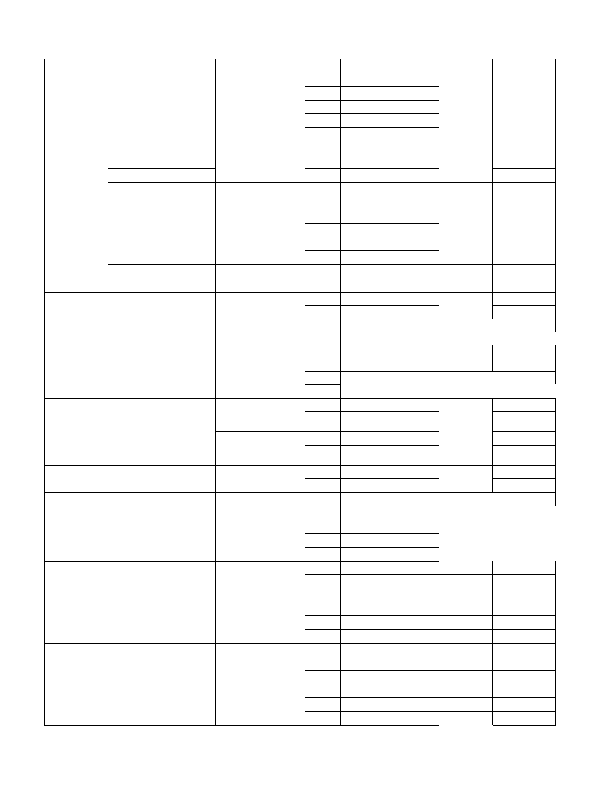
1.1.4 Replacing the ATO board or Transformer
6
Disconnect the fryer from the electrical power
supply. Locate the ATO box (see Figure 1 on
page 12), behind the JIB (Jug In Box).
Remove the cover to expose the transformer
and ATO board (see Figure 2). Mark and
unplug any wires or harnesses. Replace the
defective component and reattach all wires or
harnesses. Replace the cover. Once replaced,
reconnect the power. Power cycle all
computers after power has been restored to the
Figure 2
ATO board.
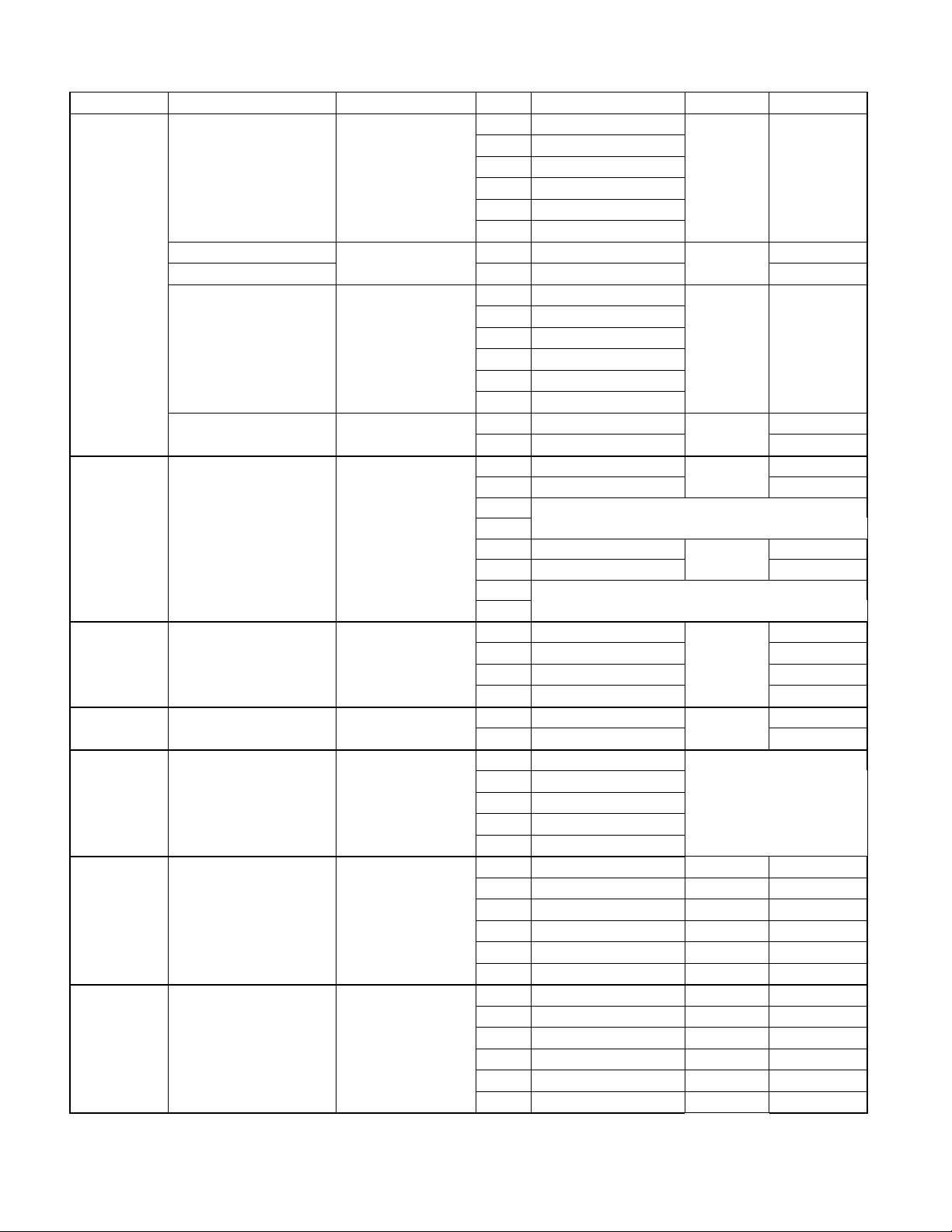
1.1.5 Replacing the ATO Pump or Solenoid
Disconnect the fryer from the electrical power
supply. Locate the ATO pump and solenoid
tree (see Figure 3), behind the ATO box. Mark
and unplug any wires or harnesses. Replace
the defective component and reattach all wires
or harnesses. Once replaced, reconnect the
power.
Figure 3
1.2 MIB (Manual Interface Board) Service Procedures
The MIB (Manual Interface Board) oversees and controls filtration. It receives and sends data
over the CAN (Controller Area Network) to and from various sensors and computers. It
activates the filtration cycle; controlling when actuators should open and close.
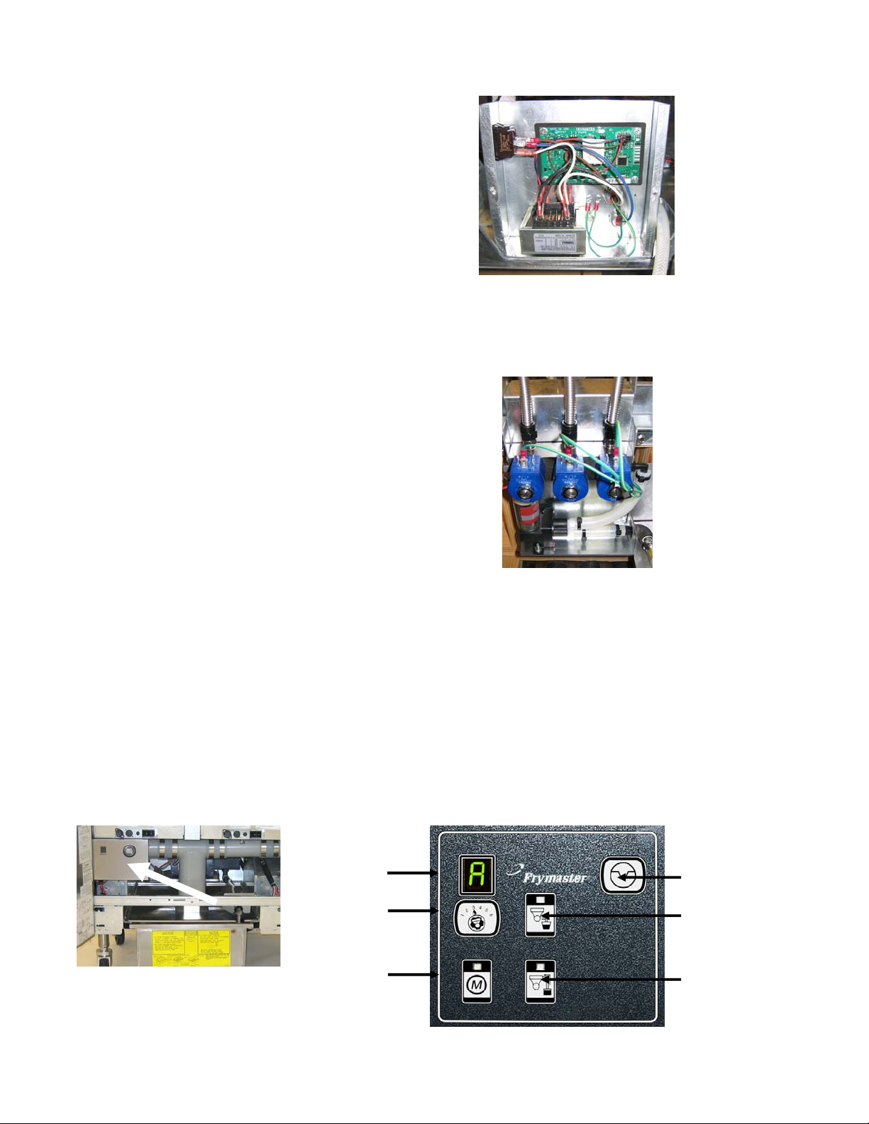
The MIB controller is located inside the left cabinet (see Figure 4). In normal operation a cover
hides the MIB controls and the LED display is visible. The cover is held in place with three torx
screws. In normal operation, an “A” is displayed for automatic mode. The MIB control board is
useful for diagnostic purposes. It allows manual operation of both the actuators and filter pump
without using the M2007 computer.
Mode Display
Reset Switch
Drain Switch
Return Switch
Figure 4: MIB controller cover.
Vat Selector
Switch
Manual /Auto
Switch
Figure 5
Page 7
Buttons and LED’s
7
Manual – This button is used to toggle between auto and manual filtration mode. A
corresponding LED is lit when in Manual mode. When pressed, a message will be sent to all
vats, indicating the mode has changed.
The following buttons are inoperable in auto mode:
Select - This button is used to scroll through available vats, choosing one to be manually filtered.
Drain – This button is used to open and close the drain on the vat indicated on the display.
When the button is pressed and the manual board is waiting for a response from the AIF board,
the corresponding LED will blink slowly. Once a response is received the LED will be
illuminated if the drain is open or extinguished if the drain is closed. If a message was not
received from the AIF board, it times out and the LED will blink rapidly.
Return – This button is used to open and close the return valve on the vat indicated on the
display. It also turns on and off the pump. When the button is pressed and the manual board is
waiting for a response from the AIF board, the corresponding LED will blink slowly. Once a
response is received, the LED will be illuminated if the return is open or extinguished if the
return is closed. If a message is not received from the AIF board, it times out and the LED will
blink rapidly. The pump is turned off first before closing the return valve or the valve will open
first before turning on the pump.
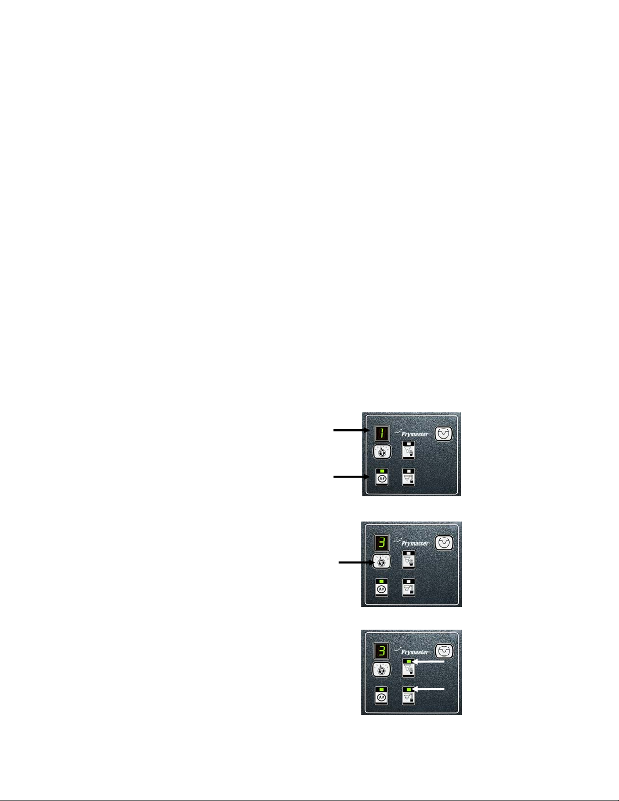
1.2.1 Manually Draining, Refilling or Filtering using the MIB board
Press the manual/auto switch to set to manual.
The LED on the manual key will illuminate
and a vat number is displayed (see Figure 6).
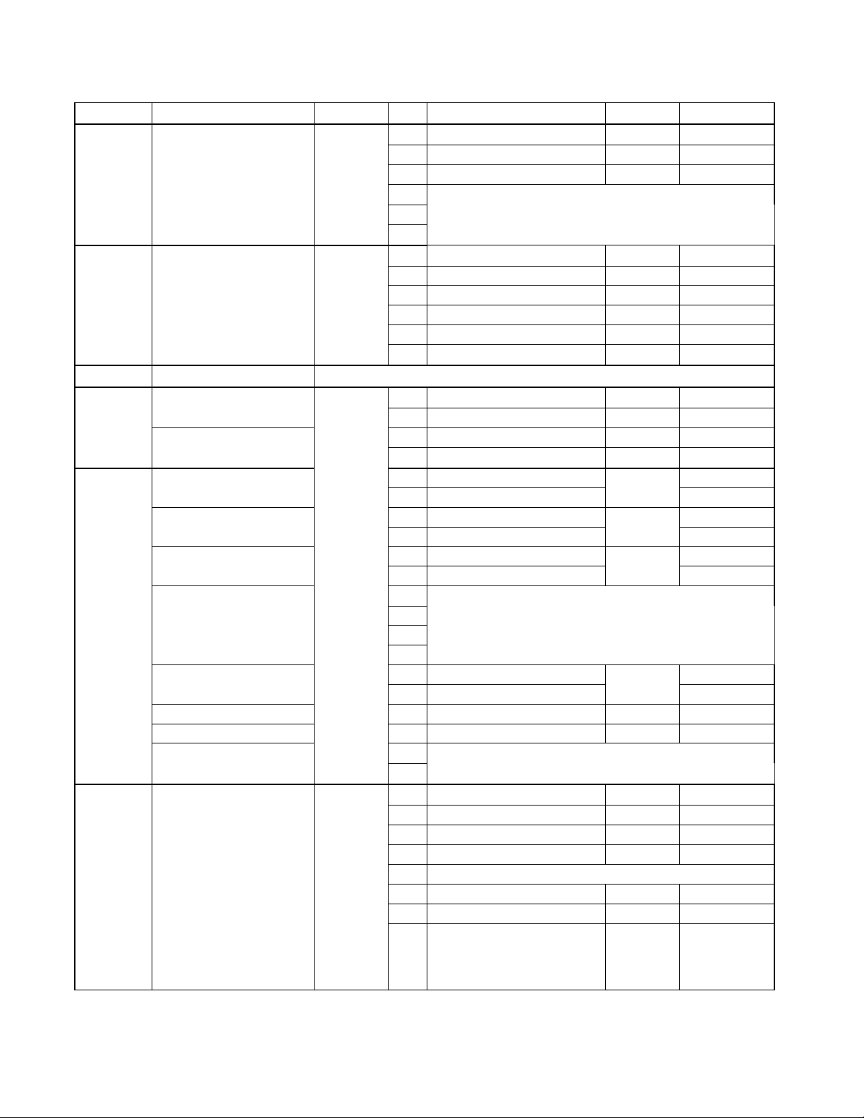
Press the vat selector switch to change vats
(see Figure 7).
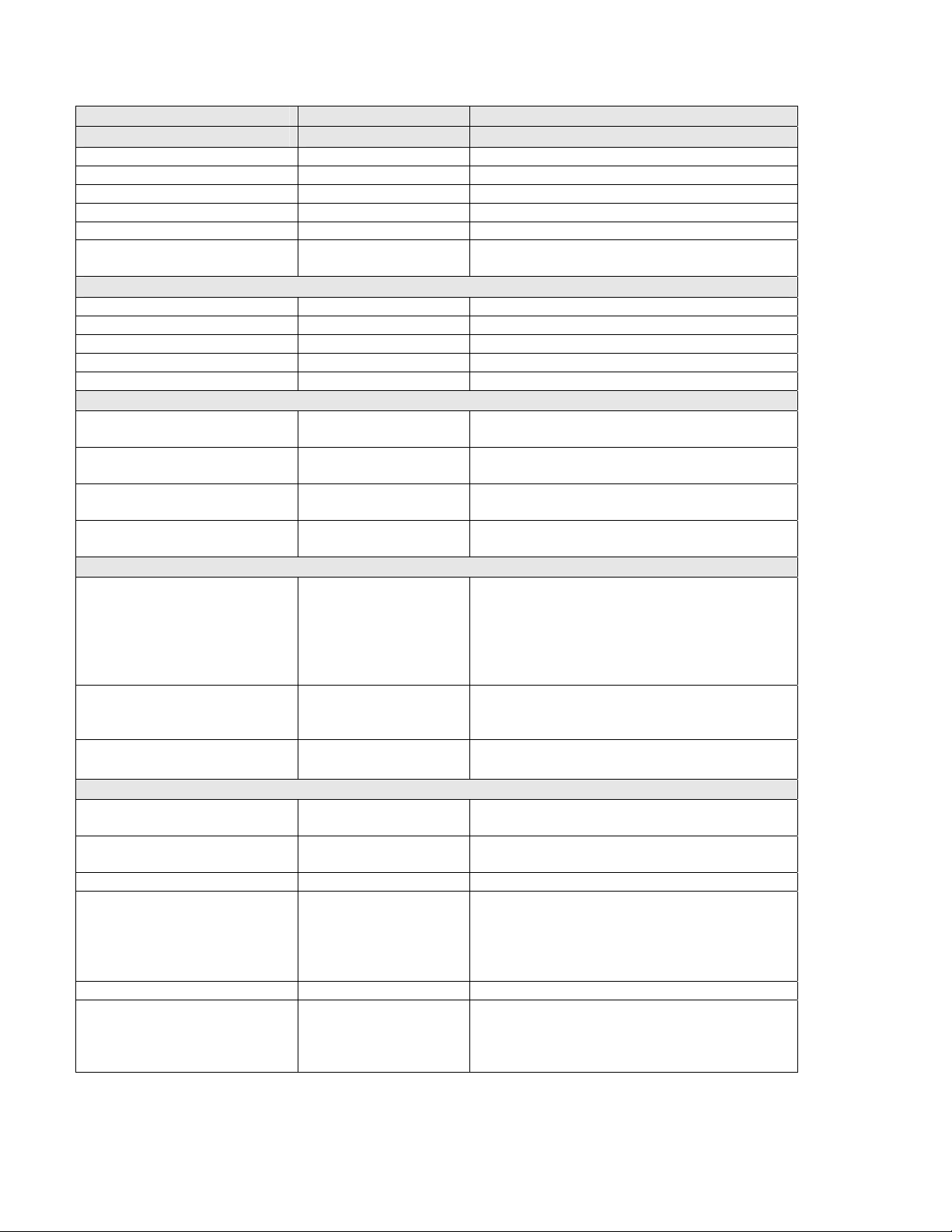
Pressing the drain or return switch illuminates
and activates the drain or return valve for the
vat indicated. Pressing both allows filtration
(see Figure 8).
Pressing the manual/auto switch will return to
automatic mode.
Figure 6
Figure 7
Figure 8
Page 8

1.2.2 MIB (Manual Interface Board) Troubleshooting
b
8
Problem Probable Causes Corrective Action
A. Ensure MIB board is in “A”
automatic mode. Press the reset
button.
B. Re move and replace cover and see if
filtration will start.
C. Replace filter relay with part number
8074482 24VDC relay.
See MIB display diagnostics on page 12
for explanation.
Check the left transformer in left
component box. Should read 24VDC. If
not replace transformer.
Press the reset switch on the top right
corner of the MIB board. This will
reinitialize the CAN system. This reset
takes about 20 seconds per vat. It could
exceed one minute before returning to
“A”.
A. Ensure the CAN bus system is
terminated at BOTH ENDS (on the
M2007 connector J6 and on the ATO
board connector J9) with a resistor
equipped 6-pin connector. The resistor
can be shorted. If so, remove the
shrink wrap and ensure that the resistor
leads are not touching.
B. Unplug and reseat all wiring harnesses
in CAN system. Check resistance
etween pins 2 and 3 on the CAN
network connectors. If checking with
resistor at the end reading should be
120 ohms.
Auto filtration won’t
start.
MIB display shows
something other
than an “A” or vat
number.
No power present at
the MIB board
MIB error will not
clear.
MIB indicates more
or less vats than
fryer has.
A. Check that MIB board is not
in manual mode.
B. Check to see that the MIB
cover is not damaged and
depressing the buttons.
C. Filter relay has failed.
An error has occurred.
Transformer has failed in left
component box.
Power surge or other electrical
problem.
A. Network is not terminated
correctly.
B. Wiring harnesses are loose
or damaged.
Page 9

Problem Probable Causes Corrective Action
9
A. Ensure the CAN bus system is
terminated at BOTH ENDS (on the
M2007 connector J6 and on the ATO
board connector J10) with a resistor
equipped 6-pin connector. The resistor
can be shorted. If so, remove the
shrink wrap and ensure that the resistor
leads are not touching.
B. Ensure all 6-pin CAN connectors are
tight between the M2007 (J6 and J7),
MIB (J1 and J2), AIF (J4 and J5) and
ATO (J10) boards.
MIB board
alternating “N” and
“r”.
Network error on the CAN bus
communication.
C. Check continuity between each color
wire on the CAN connectors into J7 on
the far right computer and J10 on back
of the ATO board (black to black,
white to white, and red to red), and
ensure there is no continuity between
different color wires (black to red, red
to white, and white to black).
D. Ensure black computer locator wires
are connected from ground to correct
pin position (see drawing 8051656
page 34 and 35).
E. Ensure all boards have the corner
ground wire attached and tightened.
Page 10
1.2.3 MIB (Manual Interface Board) Pin Positions and Harnesses
10
Connector From/To Harness # Pin # Function Voltage Wire Color
1 Ground Black
2 CAN Lo Red
J1 M2007 J7 8074546
J2 AIF J4 8074547
J3 SD Card
RTI - JIB Fill Switch
J4
Reset Switch
Transformer
Filter Relay
Blue LED
8074649
J5
J6
Pan Switch
RTI - Pump &
Solenoids
3 CAN Hi White
4
5
6
1 Ground Black
2 CAN Lo Red
3 CAN Hi White
4 5VDC+ 5VDC Black
5 24VDC 24VDC Red
6 Ground White
1 Momentary Switch - Out 5VDC Red
2 Momentary Switch - In 5VDC Black
3 Ground Red
4 Reset Green
1 24VAC Black
2 24VAC Ret
3 Pump Motor Red
4 Pump Motor
5 Blue LED + Black
6 Blue LED 7
8
9
10
11 Pan Sw + Black
12 Pan Sw 13 Ground
14 Ground
15
16
1 From RTI transformer 24VAC Black
2 Common White
3 To RTI "Add Pump" Relay 24VAC Green
4 To Waste Solenoid - 3 Way 24VAC Brown
5
6 To Fill Solenoid - 3 Way
7 Ground - Fill Solenoid
From RTI "Waste Tank Full
8
Sensor" Test Pins 1 to 8
24VAC
24VDC
24VDC
24VDC
24VAC
0VDC –
5VDC –
Not Full
Full
White
Green
White
Red
Black
Black
Red
Page 11

J7 From RTI Box
11
1 From RTI transformer 24VAC Black
2 Common White
3
4 To Waste Solenoid - 3 Way 24VAC Brown
5
6 RTI JIB Valve Fill Solenoid
7 Ground - Fill Solenoid
24VAC
Green
0VDC –
From RTI "Waste Tank Full
Sensor" Test Pins 1 to 8
8
Full
5VDC –
Not Full Red
Page 12
1.2.4 MIB (Manual Interface Board) Display Diagnostics
12
DISPLAY LEDS EXPLANATION
Drain
Vat # Drain led on Drain valve on vat # is open
Vat # Drain led off Drain valve on vat # is closed
Vat # Drain led slow blink Drain valve on vat # is opening or closing
Vat # alternating with O Drain led fast blink Problem opening drain valve on vat#
Vat # alternating with C Drain led fast blink Problem closing drain valve on vat#
Vat # alternating with d Drain led fast blink Problem with drain on vat#. (i.e. possible plugged
drain)
Return
Vat # Return led on Return valve on vat # is open
Vat # Return led off Return valve on vat # is closed
Vat # Return led slow blink Return valve on vat # is opening or closing
Vat # alternating with O Return led fast blink Problem opening return valve on vat#
Vat # alternating with C Return led fast blink Problem closing return valve on vat#
Network
Vat # alternating with n Drain led fast blink Network timeout waiting for response. Could be
on drain opening or on drain closing.
Vat # alternating with n Return led fast blink Network timeout waiting for response. Could be
on return opening or on return closing.
An “r” alternating with an “n” Network timeout waiting for a response on a reset
command.
An “F” alternating with an “n” Network timeout waiting for a success or failure
message during auto filtering.
Initial State, Configuring the system, and resetting
U The state of the battery is unknown. The manual
board is waiting for an INIT_CONFIG message
from a cooking computer. Once the message is
received the manual board will start the process
of determining which fryers have split or full
vats.
L An L will be displayed while the manual board is
contacting the cooking computers for the initial
configuration of the system.
An “r” An “r” is displayed to indicate that the system is
in the process of resetting a vat.
Miscellaneous
Vat # alternating with an “E” The actuator circuit has an issue. Check th at the
actuator is plugged in.
Vat # alternating with an “R” The vat is trying to close the corresponding drain
and return valves.
A Manual LED off The system is in auto filtration mode.
Vat # LED fast blinking
There will also be a fast
blinking LED
corresponding to the
problem valve.
Vat # Manual LED on The system is in manual mode.
P This will only be displayed in auto filtration
The system can not go into auto filtration mode
because there is a problem closing a valve on one
of the vats.
mode. It indicates that the pan is not in the
system. Any auto filtration messages received at
this time are ignored.
Page 13

13
MIB (Manual Interface Board) Display Characters
A – Auto Mode – Auto Filtration enabled.
C – Closed Valve - The display will alternate between C and the corresponding vat number and
the corresponding valve led is blinking.
d – Drain Issue- The display will alternate between d and the corresponding vat number. This
indicates the drain valve has a problem. i.e. The drain is clogged.
E – Actuator circuit is not sensing the actuator. The display will alternate between E and the
corresponding vat number. Ensure the actuator is plugged in.
F – An “F” alternating with an “n” appears when the MIB doesn’t receive a complete filtration
response from the AIF board.
L – Loading - Loading the vat configuration from the cooking computers. The MIB has been in
an unknown state (i.e. Initial startup) and is reloading information. This is not displayed often.
n – Network Error - An “n” displayed alternating with another character indicates a network
error. An “r” alternating with an “n” indicates a network timeout on a reset. An “F” alternating
with an “n” appears if the manual board never receives a complete filtration response from the
AIF board. If a vat number is alternating with an “n”, either the drain or the return led is also
blinking, indicating a timeout error opening or closing the drain.
O – Open Valve - The display will alternate between O and the corresponding vat number and
the corresponding valve led is blinking.
P – Pan Switch – Filter Pan is out of the battery. Filtration is suspended.
r – Reset Switch - Reset the vat closes all of the valves on the vat. If displayed for some time,
there is probably a problem with the board.
U – The battery is not configured. The manual board must receive a message from a cooking
computer telling it to initialize the battery.
1 – 8 – These are the numbers that correspond to the vats. These numbers are displayed in
Manual mode.
Page 14

1.2.5 MIB (Manual Interface Board) Auto Filtration Failure Scenarios
14
Failure Display Solution
Cannot open drain valve. Vat # alternating with O, fast
Check drain valve.
blinking drain LED.
No message from the cooking
computer, indicating that the oil
has drained out.
Vat # alternating with d, fast
blinking drain LED.
Close drain valve.
Cannot open return valve
Vat # alternating with O, fast
blinking return LED.
Close drain valve.
Cannot close drain valve
Vat # alternating with C, fast
blinking drain LED.
Turn off pump. Close Return
Valve. Open Drain valve in
case something is stuck.
Actuator is not plugged in. Vat # alternating with E. Plug in actuator.
Cannot close return valve
Vat # alternating with C, fast
blinking return LED.
Check return valve.
Manual board never gets a
response back from AIF board
“N” is displayed. Check network cable from
MIB plug J2 to AIF plug J4.
indicating success or failure in
filtering.
1.2.6 Replacing the MIB Board
Disconnect the fryer from the electrical power supply. Remove the torx screws from the MIB
cover, exposing the MIB board (see Figure 9). Removing the four nuts in the corners
disconnects the MIB board. Carefully remove the plugs on the rear of the board (see Figure 10).
Replace with a new MIB board and reverse steps to reassemble. Once replaced, reconnect the
power.
The board will need to be readdressed to the system. Readdress the fryer by pressing and
holding
3and 4 simultaneously for TEN seconds until a third chirp is heard and code
appears. Enter 2007. The MIB display will display L for several seconds followed by the vat
number alternating with “r” until the readdress is complete. When the readdress is finished, the
MIB board will display A. This step must be done when a MIB board is replaced. The
readdress procedure can be done from any one M2007 computers in the bank.
Figure 9
Figure 10
Page 15

1.3 AIF (Automatic Intermittent) Filtration Service Procedures
15
The AIF (Automatic Intermittent Filtration)
board controls the actuators that open and
close the drain and return valve. The AIF
boards are located inside a protective housing,
under each frypot (see Figure 11).
Figure 11
1.3.1 AIF Troubleshooting
Problem Probable Causes Corrective Action
A. Ensure the actuator is plugged
into the proper connection.
B. Check power on the connector
of the problem actuator while
trying to manually open or close
an actuator. Pins 1 (Black) and
4 (White) should read +24VDC
when trying to open an actuator.
Pins 2 (Red) and 4 (White)
should measure -24VDC when
trying to close an actuator). If
either one of these voltages are
missing, the AIF board may be
bad. Test the actuator by
plugging into another connector
to open or close the actuator. If
the actuator operates, the board
is bad. Replace the board.
C. If proper voltages are present at
the connector and actuator
doesn’t operate, actuator may be
bad. Replace the actuator.
A. Ensure the actuator is plugged
into correct connection.
B. Ensure the locator pin is in
proper position in plug J2. See
table B on page 37-40.
Actuator doesn’t
function.
Actuator functions
on wrong vat.
A. Actuator is unplugged.
B. AIF board failure.
C. Actuator is bad.
A. Actuator plugged into wrong
connector.
B. Locator pin is in wrong position.
Page 16

1.3.2 AIF (Auto Intermittent Filtration) Actuator Board Pin Positions with
16
Thermal Sensors
Pin
Connector From/To Harness PN
J1
FV Return
Actuator
N/A
FV AIF RTD
DV AIF RTD
O/Flow Sensor
& Fill Sensor
8074551 (FV)
J2
Pressure Switch
(Gas)
8074550 (DV)
Locator Pin
Locator
J3
DV Return
Actuator
N/A
8074547
J4
MIB J2 or
AIF J5
AIF Board
Communication
and Power
8074547
J5
AIF J4 or
ATO J10
AIF Board
Communication
and Power
J6 FV Drain N/A
J7 DV Drain N/A
#
Function Voltage
1 Ret + (Open) 24VDC Black
2 Ret – (Closed) 24VDC Red
3 Ret Position Purple
4 Ground White
1 Ground White
2 FV - Temp Red
3 Ground White
4 DV - Temp Red
5 FV - Top In 16VDC Black
6 FV- Top Out 16VDC Red
7 DV-Top In 16VDC White
8 DV- Top Out Green
DV – Press Sw (Gas)
9
FV – Press Sw (Gas)
10
11 Locator Vat #5
12 Locator Vat #4
13 Locator Vat #3
14 Locator Vat #2
15 Locator Vat #1
16 Locator Signal Black
1 Ret + (Open) 24VDC Black
2 Ret – (Closed) 24VDC Red
3 Ret Position Purple
4 Ground White
1 Ground Black
2 CAN Lo Red
3 CAN Hi White
4 5VDC+ 5VDC Black
5 24VDC 24VDC Red
6 Ground White
1 Ground Black
2 CAN Lo Red
3 CAN Hi White
4 5VDC+ 5VDC Black
5 24VDC 24VDC Red
6 Ground White
1 Drain + (Open) 24VDC Black
2 Drain – (Closed) 24VDC Red
3 Drain Position Purple
4 Ground White
1 Drain + (Open) 24VDC Black
2 Drain – (Closed) 24VDC Red
3 Drain Position Purple
4 Ground White
Wire
Color
Black
Page 17

17
1.3.3 AIF (Auto Intermittent Filtration) Actuator Board Pin Positions with RTD
Sensor
Connector From/To Harness PN
J1 FV Return N/A
FV AIF RTD
DV AIF RTD
8074551 (FV)
J2
Pressure Switch
(Gas)
Locator Pin
Locator
J3 DV Return N/A
J4
J5
MIB J2 or
AIF J5
AIF J4 or
ATO J10
J6 FV Drain N/A
J7 DV Drain N/A
8074550 (DV)
8074547
AIF Board
Communication
and Power
8074547
AIF Board
Communication
and Power
Pin
#
Function Voltage
1 Ret + (Open) 24VDC Black
2 Ret – (Closed) 24VDC Red
3 Ret Position Purple
4 Ground White
1 Ground White
2 FV - Temp Red
3 Ground White
4 DV - Temp Red
5
6
7
8
DV – Press Sw (Gas)
9
FV – Press Sw (Gas)
10
11 Locator Vat #5
12 Locator Vat #4
13 Locator Vat #3
14 Locator Vat #2
15 Locator Vat #1
16 Locator Signal Black
1 Ret + (Open) 24VDC Black
2 Ret – (Closed) 24VDC Red
3 Ret Position Purple
4 Ground White
1 Ground Black
2 CAN Lo Red
3 CAN Hi White
4 5VDC+ 5VDC Black
5 24VDC 24VDC Red
6 Ground White
1 Ground Black
2 CAN Lo Red
3 CAN Hi White
4 5VDC+ 5VDC Black
5 24VDC 24VDC Red
6 Ground White
1 Drain + (Open) 24VDC Black
2 Drain – (Closed) 24VDC Red
3 Drain Position Purple
4 Ground White
1 Drain + (Open) 24VDC Black
2 Drain – (Closed) 24VDC Red
3 Drain Position Purple
4 Ground White
Wire
Color
Black
Page 18

1.3.4 Replacing an AIF (Automatic Intermittent Filtration) board
18
Disconnect the fryer from the electrical power supply. Locate the AIF board to be replaced
under a frypot. Mark and unplug the harnesses. The AIF board assembly is held in place with
one screw in the front of the assembly (see Figure 12). Remove the screw and the front of the
assembly drops down (see Figure 13) and the back tab slides out of the bracket attached to the
frypot (see Figure 14). Reverse steps to reassemble, ensuring that the new AIF assembly slides
into the slot in the rear of the bracket.
Figure 12 Figure 13 Figure 14
1.3.5 Replacing an Actuator
Disconnect the fryer from the electrical power supply. Locate the actuator to be replaced under a
frypot and mark and unplug the actuator. The actuators are held in place by two clevis pins that
are held in by cotter ring pins (see Figure 15). Remove both clevis pins and remove the actuator.
Attach the new actuator with the rear clevis pin and cotter ring pin first (see Figure 16). With the
actuator attached with the rear clevis pin only, adjust the new actuator by rotating the shaft until
the holes of the actuator and valve plate are aligned. Rotating the shaft clockwise, adjusts it
outward. While rotating it counterclockwise adjusts the shaft inward. Insert the clevis pin and
the cotter ring pin to secure. If a return valve was replaced, filter a different vat of oil. If bubbles
appear in the vat where the actuator was replaced, further adjustment is necessary. Take out the
pins and adjust the valve until no bubbles are present in the vat. Reinsert the pins to secure the
actuator.
Figure 15 Figure 16
Page 19

1.4 M2007 Computer Filtration Service Procedures
b
19
1.4.1 M2007 Computer Troubleshooting
Problem Probable Causes Corrective Action
A. Press the ON/OFF switch to turn
the computer on.
B. This fryer has two cords: a
computer power cord and a main
power cord. If the computer
cord is not plugged in, the
computer will not activate.
Verify computer power cord is
plugged in and that circuit
breaker is not tripped.
C. Swap the computer with a
computer known to be good. If
computer functions, replace the
computer.
D. Swap with a harness known to
e good. If computer functions,
replace the harness.
E. If any component in the power
supply system (including the
transformer and interface board)
fail, power will not be supplied
to the computer and it will not
function.
Power cycle the computer using the
master switch on the component
box next to the fuse.
A. Wait until the previous
filtration cycle ends or an error
is cleared to start another
filtration cycle.
B. Press reset button and wait at
least 60 seconds. Computer
should clear and return to
normal operation once
complete.
Remove and discard product.
Press and hold the cook butto n for
three seconds under the display
with the error to remove the error.
Reset the setpoint of the vat before
trying to cook product.
No Display on
Computer.
Computer locks up.
M2007 display
shows filter
busy.
M2007 display
shows REMOVE
DISCARD.
A. Computer not turned on.
B. No power to the fryer.
C. Computer has failed.
D. Damaged computer wiring
harness.
E. Power supply component or
interface board has failed.
Computer error.
Another filtration cycle is still in
process.
In non-dedicated mode a product is
dropped that has a different setpoint
than the current vat temperature.
Page 20

Problem Probable Causes Corrective Action
20
A. Pull filter pan out and fully
reinsert into fryer.
B. Ensure the filter pan magnet is
in place and if missing replace.
C. If the filter pan magnet is fully
against the switch and
computer continues to display
chk pan, switch is
possibly defective.
M2007 computers may be
programmed to display in either
Fahrenheit or Celsius. Press and
hold 3and 4simultaneously until
code appears. Enter 1658.
The computer displays OFF. This
toggles the temperature from F° to
C° or vice versa. Turn the
computer on to check temperature
and see the temperature scale. If
the desired scale is not displayed,
repeat.
This in an indication of a
malfunction in the temperature
control circuitry, including a
failure of the high-limit thermostat.
This is displayed only during a test
of the high-limit circuit and
indicates that the high-limit has
opened properly.
This display is normal when the
fryer is first turned on while in the
melt cycle mode. To bypass the
melt cycle press and hold a #2
product button under the LCD
display until a chirp is heard. The
alarm will chirp and the computer
displays EXIT MELT alternating
with YES NO. Press the #1 YES
button to exit melt. It may appear
for a short while if a large batch of
frozen product is added to the
frypot. If the display never goes
out, the fryer is not heating.
M2007 display
shows chk pan.
M2007 display is in
wrong temperature
scale (Fahrenheit or
Celsius).
M2007 display
shows hot-hi-1.
M2007 display
shows HI-LIMIT.
M2007 display
shows low temp.
A. Filter pan is not fully set into fryer.
B. Missing filter pan magnet.
C. Defective filter pan switch.
Incorrect display option programmed.
Frypot temperature is more than
410ºF (210ºC) or, in CE countries,
395ºF (202ºC).
Computer in high-limit test mode.
Frypot temperature is between 180°F
(82°C) and 315°F (157°C).
Page 21

Problem Probable Causes Corrective Action
21
M2007 display
shows
PROBE
FAILURE.
M2007 display
shows PROBE
FAILURE
with
alarm sounding.
M2007 display
shows IGNITION
FAILURE.
Computer will not
go into program
mode or some
buttons do not
actuate.
M2007 display
shows HI 2 BAD.
Heat indicator off
upon initial startup.
Display shows hi or
hot with alarm
sounding.
M2007 display
shows ignition
FAILURE with
alarm sounding.
Heating indicator is
on, but fryer is not
heating.
M2007 display
shows IGNITION
FAILURE and
alarm sounds, but
fryer operates
normally (false
alarm).
Problem with the temperature
measuring circuitry including the
probe.
Damaged computer wiring harness or
connector.
Open drain valve, failed computer,
failed interface board, open highlimit thermostat.
Failed computer. Replace computer
Computer in high-limit test mode.
Failed computer.
Drain valve not fully closed.
Failed computer.
This indicates a problem within the
temperature measuring circuitry
that is beyond the scope of
operator troubleshooting.
Swap the computer wiring harness
with one known to be good. If
problem is connected replace
harness.
This indicates that the fryer is not
heating. It is displayed if the fryer
loses its ability to heat oil. It is
also displayed when the oil
temperature is above 450°F
(232°C) and the high-limit
thermostat has opened, halting the
heating of the oil. Verify that the
drain valves are fully closed.
This is displayed only during a test
of the high-limit circuit and
indicates that the high-limit has
failed.
Replace computer.
Press the reset switch on the MIB
board. All drain valves should
close. Using the ON/OFF switch,
turn the computer OFF and then ON
again.
Replace computer.
Page 22

Problem Probable Causes Corrective Action
E
C
R
22
M2007 display
shows low temp,
heating indicator
cycles on and off
normally but fryer
does not heat.
M2007 display
shows GET MGR
followed by ENTER
MGR CODE.
M2007 display
shows software for
only M2007 or MIB
but not all boards.
M2007 display
shows ERROR RM
SDCRD
1.4.2 M2007 Useful Codes
To enter any of the following codes: Press and hold 3and 4simultaneously for TEN seconds
and a third chirp sounds. Release the buttons and code appears.
Reset Factory Menu - Enter 3322. The computer display flashes and quickly counts from
1-40 and switches to off. (NOTE: This will delete any hand-entered menu items).
Reset CALL TECH Message - Enter 1000. Computer display switches to off.
Change from F° to C° - Enter 1658. The computer displays off. Turn the computer on
and check temperature to see the temperature scale. If the desired scale is not displayed, repeat.
Enter Tech Mode – Enter 1650.
Readdress LOV configuration after changing an MIB board – Enter 2007.
PASSWORDS
To enter level one, level two passwords: Press and hold the TEMP and INFO buttons
simultaneously until level 1 or level 2 is displayed. Release the buttons and ENTER Code
appears.
Fryer Setup, Level One, Level Two and Get Manager Password – Enter 1234.
Usage Password – Enter 4321.
A. Failed computer.
B. Damaged computer wiring
harness.
A filter error has occurred due to dirty
or clogged filter pad or paper, clogged
filter pumps, filter pump thermal
overload, or an actuator problem.
Loose or damaged harness
Defective SD Card
A. Replace computer.
B. Replace computer wiring
harness.
nter the MGR CODE (1234)
and follow the steps on the
flowchart on the next page.
heck that all harnesses between
M2007’s, MIB, AIF and ATO are
secure.
eplace card with another card.
Page 23

1.4.3 Get Mgr Flowchart
23
Page 24

1.4.4 M2007 Menu Summary Tree
24
Reflected below are the major programming sections in the M2007 and the order in which submenu headings will be
found under the sections in the Installation and Operation Manual.
Adding New Product Menu Items See pg. 4-12
Storing Product Menu Items in Product Buttons See pg. 4-15
Draining, Refilling, and Disposing of Oil and Boil-out See pg. 4-16
Filter Menu See pg. 4-20
1. Auto Filter See pg. 5-2
2. Maint Filter See pg. 5-8
3. Dispose See pg. 4-16 thru 4-20
4. Drain to Pan See pg. 4-21
5. Fill Pot from Drain Pan See pg. 4-22
6. Fill Pot from Bulk See pg. 4-22
Programming
Level 1 Program See pg. 4-24
1. Product Selection See pg. 4-24
a. Name
b. Cook Time
c. Temp
d. Cook ID
e. Qual Tmr
f. Duty Time 1
g. Duty Time 2
h. AIF Disable
i. Assign Btn
2. AIF Clock See pg. 4-25
a. Disabled
b. Enabled
3. Deep Clean Mode (Boil Out) See pg. 4-27
4. High-Limit Test See pg. 4-30
a. Hi-Limit Test 1
b. Hi-Limit Test 2
5. Fryer Setup See pg. 4-9
Level 2 Program (Manager Level) See pg. 4-31
1. Prod Comp Sensitivity for product See pg. 4-32
2. E-Log Log of last 10 error codes See pg. 4-33
3. Passwords
a. Setup
b. Usage
c. Level 1
d. Level 2
e. Get Mgr
4. Alert Tone Volume and Tone See pg. 4-34
a. Volume 1-9
b. Tone 1-3
5. Filter After Sets number of cooks before filter prompt See pg. 4-35
6. Filter Time Sets amount of time between filter cycles See pg. 4-36
Info Mode Menu See pg. 4-37
Full/Split Vat Configuration
1. Filter Stats See pg. 4-37
2. Review Usage See pg. 4-38
3. Last Load See pg. 4-40
Change passwords See pg. 4-33
Page 25

1.4.5 M2007 Pin Positions and Harnesses
25
Pin
Connector From/To Harness PN
Interface
J2
J6
J7
J9 ONLY USED ON NON-AIF UNITS
J10
J11 SD Card
Board to
Computer
Next M2007
J7 or Network
Resistor
MIB J1 or
previous
M2007 J6
Interface
Board Ground
to Computer
8074199
SMT Computer to
Interface Board
Harness
8074546
Computer
Communication
Harness
8074546
Computer
Communication
Harness
8074573
Computer Locator
Harness
# Function Voltage Wire Color
1 12VAC In 12VAC
2 Ground
3 12VAC In 12VAC
4 FV Heat Demand
5 V Relay 12VDC
6 DV Heat Demand
7 R/H B/L 12VDC
8 Analog Ground
9 L/H B/L 12VDC
10 ALARM
11 Sound Device 5VDC
12 ALARM
13 FV Probe
14 Common Probes
15 DV Probe
16
17
18
19
20
1 Ground Black
2 CAN Lo Red
3CAN Hi White
4
5
6
1 Ground Black
2 CAN Lo Red
3CAN Hi White
4
5
6
1 Vat #1
2 Vat #2
3 Vat #3
4 Vat #4
5 Vat #5
6
Black
Black
Page 26

1.5 Loading and Updating Software Procedures
26
1.5.1 Loading Software from an SD card to MIB and AIF boards
To update MIB or AIF software in the field follow these steps:
1. Switch all computers to OFF. With the computer displaying OFF, press the TEMP
button to check current M2007/MIB/AIF software version.
2. Remove the two screws on the right side cover plate of the MIB board.
3. With the MIB displaying “A” insert the SD card with the new software, with the card
contacts facing out and the notch on the bottom left, into the slot on the right side of
the MIB board (see Figure 17 and 18).
4. Once inserted, watch for a period in the display to appear on the bottom right of the
MIB display, indicating the software is being downloaded. If a period does not
appear, the software on the card and on the computer may be the same version, or the
boot loader software missing or corrupt. It will not update. If this happens, contact
Frymaster.
5. The period blinks several times while loading. Wait for a minimum of two minutes
and the period in the display stays off.
6. Remove the SD card from the MIB.
7. If only updating the MIB or AIF boards remove power from the MIB by carefully
removing the16-pin harness behind the MIB board or the five-pin control power cord
on the rear of the unit. If updating all the software update the MIB and then the
M2007 and then remove all power from the fryer using the five-pin control power
cord on the rear of the unit.
8. Restore power to the MIB to reboot the system.
9. A successful upgrade is confirmed by a “cLc” display on the MIB board upon restart
followed by “r, 1, r, 1, r, 2, r, etc ending with A”. If this does not happen, try
reloading the software.
10. Verify software upgrade by pressing the TEMP button with the computer OFF to
check the updated MIB/AIF version.
Figure 17 Figure 18
Page 27

27
Page 28

1.5.2 Loading Software from an SD card to an M2007 Computer
28
To update M2007 and ATO software in the field, follow these steps:
1. Switch all computers to OFF. With the computer displaying OFF, press the TEMP
button to check current M2007/MIB/AIF software version.
2. With the computer displaying OFF, remove the two screws on the left side cover plate of
the M2007 board.
3. With the computer folded down and the MIB displaying A, insert the SD card, with the
contacts facing down and the notch on the bottom right (see Figure 19 and 20), into the slot
on the left side of the M2007.
4. Once inserted, FWUPD appears on the left display and SCCRCOK appears on the right.
Numbers count up on the right display.
5. The display then changes to FWLOAD on the left; numbers count up on the right.
6. The computer displays OBFCRC. If updating ATO software the computer will display
FWU ATO on the left and will count down from 2500 on the right.
7. When the update is complete the M2007 displays DONE on the left and RM SDCRD on
the right.
8. Remove the SD card using the fingernail slot on the top of the SD card.
9. If updating the M2007 or ATO board, remove power to the M2007 by removing the 20-pin
J2 plug on the rear of the computer, or remove power to the fryer to reboot the computer. If
updating all the software update the MIB and then the M2007 and then remove all power
from the fryer using the five-pin control power cord on the rear of the unit.
10. Restore power to the M2007 – There is short delay prior to the computer powering up and
displaying OFF.
11. Repeat steps 1-10 for all computers.
12. With the computer displaying OFF, verify software update by pressing the TEMP button
to check updated M2007/MIB/AIF version.
13. If the software is adding fields that require passwords, enter Level 2 mode and change
passwords.
Figure 19 Figure 20
Page 29

29
Page 30

1.6 Tech Mode
30
Tech mode allows technicians to reset passwords set in levels one and two. It also resets the
time and date. It also allows the technician to access the fryer main setup mode.
1. Press and hold 3and 4 simultaneously for TEN seconds until a third chirp is heard and
CODE is displayed.
2. Enter 1650.
3. The computer displays TECH MODE and changes to CLEAR PASSWORDS.
4. Press the 9 (1) button to accept selection and clear the passwords.
5. The computer displays CLEAR PASSWORDS on the left and COMPLETE on the
right. This clears any passwords set up under levels one and two.
6. Press the ubutton to toggle to CLEAR SIGNATURE.
7. Press the 9 (1) button to accept the change.
8. The computer displays CLEAR SIGNATURE on the left and COMPLETE on the
right. This resets the date and time.
9. Press the ubutton to toggle to FILTER PAD TIME on the left and 25 on the right.
(25 hours is the default time to change the pad)
10. Press the 8 (2) button to accept changes and exit.
11. The computer displays OFF. Proceed to the next page to enter the setup mode.
Page 31

1.7 Fryer Setup Mode
31
Setup mode allows technicians to set the time, date, temperature format, language, fryer type,
vat type and oil system.
1. With the computer displaying OFF, press and hold the TEMP and INFO buttons until
LEVEL 1 is displayed.
2. Press the TEMP key once to FRYER SETUP.
3. The computer displays FRYER SETUP and then changes to ENTER CODE.
4. Enter 1234.
5. Press the 9 (1) button to accept selection.
6. The computer displays TIME FORMAT on the left and 12 HR on the right.
7. Press the 4button to toggle between 12 HR and 24 HR time formats.
8. Press the 9 (1) button to accept selection.
9. The computer displays ENTER TIME on the left and HH:MM on the right.
10. Enter the time in hours and minutes using the 0-9 keys.
11. Press the 9 (1) button to accept selection.
12. The computer displays ENTER TIME on the left and am on the right.
13. Press the 4button to toggle between AM and PM if 12 HR time format was chosen.
14. Press the 9 (1) button to accept selection.
15. The computer displays DATE FORMAT on the left and US on the right.
16. Press the
4button to toggle between US and INTERNTL time formats.
17. Press the 9 (1) button to accept selection.
18. The computer displays enter date on the left and MM-DD-YY or DD-MM-YY
on the right.
19. Enter the date using the 0-9 keys.
20. Press the 9 (1) button to accept selection.
21. The computer displays language on the left and English on the right.
Page 32

32
22. Press the 4button to toggle between ENGLISH, FRENCH, FRENCH CANADIAN,
SPANISH, PORTUGUESE, GERMAN and SWEDISH languages.
23. Press the 9 (1) button to accept selection.
24. The computer displays FRYER TYPE on the left and eLEC on the right.
25. Press the 4button to toggle between ELECTRIC and GAS fryers.
26. Press the 9 (1) button to accept selection.
27. The computer displays VAT TYPE on the left and SPLIT on the right.
28. Press the 4button to toggle between SPLIT and FULL vats.
29. Press the 9 (1) button to accept selection.
30. The computer displays oil system on the left and jib on the right.
31. Press the 4button to toggle between JIB and BULK oil systems.
32. Press the 9 (1) button to accept selection.
33. The computer displays temperature on the left and f on the right.
34. Press the 4button to toggle between F° and C° temperature scales.
35. Press the 9 (1) button to accept selection.
36. The computer displays FRYER Setup for three seconds and the computer displays
off on both sides.
Page 33

1.8 RTI Service Issues
33
1.8.1 RTI MIB Tests
Normal measurements, measured on MIB J6 8 pin connector with
everything connected.
AC voltage measurements:
Pin 1 to Pin 2 - 24 VAC.
Pin 2 to Pin 3 - 24 VAC when RTI add pump is on, 0 VAC when it is off.
Pin 4 to Pin 5 - 24 VAC when RTI waste valve is on, 0 VAC when it is off.
Pin 6 to Pin 7 - 24 VAC when RTI JIB valve is on, 0 VAC when it is off.
DC voltage measurements:
Pin 1 to Pin 8 - 0 VDC when waste tank is full, 5 VDC when it is not full.
Troubleshooting.
The valves and pump should be off while MIB is resetting, 5 seconds or so after a power on or after
pressing the reset button; if any are on during reset then the MIB board is bad or wires are shorted.
If JIB valve is not opening:
Measure when JIB valve should be opened:
1. Voltage at MIB board from Pin 1 to Pin 2, should be 24 VAC; if not then check connections from RTI
24VAC transformer and check transformer.
2. Voltage at MIB board from Pin 6 to Pin 7, should be 24 VAC; if not then MIB board is bad or wires to
JIB valve are shorted or both.
3. Voltage at JIB valve, should be 24 VAC; if not then check wiring from MIB board.
If Waste valve is not opening:
Measure when Waste valve should be opened:
1. Voltage at MIB board from Pin 1 to Pin 2, should be 24 VAC; if not then check connections from RTI
24VAC transformer and check transformer.
2. Voltage at MIB board from Pin 4 to Pin 5, should be 24 VAC; if not then MIB board is bad or wires to
Waste valve are shorted or both.
3. Voltage at Waste valve, should be 24 VAC; if not then check wiring from MIB board.
If Add pump is not operating:
Measure when Add pump should be on:
1. Voltage at MIB board from Pin 1 to Pin 2, should be 24 VAC; if not then check connections from RTI
24VAC transformer and check transformer.
2. Voltage at MIB board from Pin 2 to Pin 3, should be 24 VAC; if not then MIB board is bad or wires to
pump relay are shorted or both.
3. Voltage at Add pump relay, should be 24 VAC; if not check wiring from MIB board.
Waste full signal:
Pin 1 to Pin 8 should be 0 VDC when full, 5 VDC when not full; if no level change, then bad
connection from RTI switch or MIB board is bad.
Page 34

1.8.2 RTI LOV Wiring with RTI Switchbox
34
Page 35

1.8.3 RTI LOV TEST QUICK REFERENCE
35
DISPOSE TO WASTE, REFILL POT FROM BULK:
1. Hold down “filter” button until computer beeps twice.
2. Scroll down to “dispose” using “Info" button then press “√” button to select.
3. Select “Yes” by pressing “√” to dispose of oil in pot (this is a timed function).
4. “Vat Empty” is displayed
5. Select “Yes” (by pressing “√”) if it is empty or “No” (by pressing “X”) if vat still has oil.
6. “Clean Vat Complete” is displayed
7. Press “√” if vat is clean (oil disposes automatically for 60 seconds, if this is selected) and “X”
if it is not clean and needs to be.
8. “Engage Dispose” is displayed. Switch the RTI switch to dispose.
9. Press the “√” to start disposal. “Pan to Waste” displayed.
10. “Pan Empty” is displayed
11. Press “√” if oil in filter pan is empty. Select “X” if pan still has oil in it.
12. “Disengage Dispose” is displayed. Switch off the RTI dispose switch.
13. Press “√” when RTI dispose switch is off.
14. “Fill Pot From Bulk” is displayed.
15. Press “√” if you wish to fill pot.
16. Hold down “√” to fill pot to desired level.
17. Press “X” to Exit program.
DISPOSE TO WASTE:
1. Hold down “filter” button until computer beeps twice.
2. Scroll down to “dispose” using “Info” button and press “√” button to select
3. Select “Yes” by pressing “√” to dispose of oil in pot (this is a timed function).
4. “Vat Empty” is displayed
5. Select “Yes” (by pressing “√”) if it is empty or “No” (by pressing “X”) if vat still has oil.
6. “Clean Vat” is displayed
7. Press “√” if vat is clean (oil disposes automatically for 60 seconds, if this is selected) and “X”
if it is not clean and needs to be.
8. “Engage Dispose” is displayed. Switch the RTI switch to dispose.
9. Press the “√” to start disposal. “Pan to Waste” displayed.
10. “Pan Empty” is displayed
11. Press “√” if oil in filter pan is empty. Select “X” if pan still has oil in it.
12. “Disengage Dispose” is displayed. Switch off the RTI dispose switch.
13. “Fill Pot From Bulk” is displayed.
14. Press “X” if you wish to leave pot empty and exit program.
FILL POT FROM BULK:
1. Hold down “filter” button until computer beeps twice.
2. Scroll down to “Fill Pot From Bulk”
3. Press “√” if you wish to fill pot.
4. Hold down “√” to fill pot to desired level.
5. Press “X” to Exit program.
FILL JUG FROM BULK:
1. When “Orange” indicator light is on, the pot top-off jug is empty.
2. To refill jug press ADD button on the RTI box located on back side of door that accesses jug.
3. Hold down button until oil is to desired level in jug.
Page 36

1.9 Wiring Diagrams
36
1.9.1 LOV Electric Wiring Diagram with Thermal Sensor
RESET
SWITCH
Page 37

1.9.2 LOV Electric Wiring Diagram with RTD
37
RTI SWITCHBOX
J3 J2 J1
J5
Page 38

1.9.3 LOV Gas Wiring Diagram with Thermal Sensor
38
Page 39

1.9.4 LOV Gas Wiring Diagram with RTD
39
 Loading...