

Page 1
NON
-
CE &
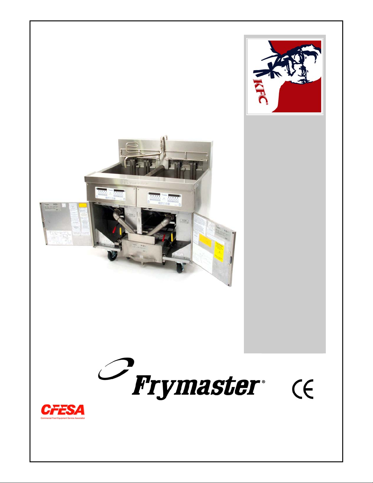
Installation & Operation Manual
KSCFH18E Cool Zone
Series Electric Fryers
PARTS LIST
INCLUDED
Frymaster, a member of the Commercial Food Equipment Service Association, recommends
using CFESA Certified Technicians.
24-Hour Service Hotline 1-800-551-8633
Price: $10.00
819-5678
August 2002
Page 2
Please read all sections of this manual and retain for future reference.
NOTICE
This appliance is intended for professional use only and is to be operated by qualified
personnel only. A Frymaster/Dean Factory Authorized Service Center (FASC) or other qualified
professional should perform installation, maintenance, and repairs. Installation, maintenance,
or repairs by unqualified personnel may void the manufacturer’s warranty. See Chapter 1 of
this manual for definitions of qualified personnel.
NOTICE
This equipment must be installed in accordance with the appropriate national and local codes of
the country and/or region in which the appliance is installed.
NOTICE
Drawings and photos used in this manual are intended to illustrate operational, cleaning and
technical procedures and may not conform to onsite management operational procedures.
NOTICE TO OWNERS OF UNITS EQUIPPED WITH COMPUTERS
U.S.
This device complies with Part 15 of the FCC rules. Operation is subject to the following two
conditions: 1) This device may not cause harmful interference, and 2) This device must accept
any interference received, including interference that may cause undesired operation. While
this device is a verified Class A device, it has been shown to meet Class B limits.
CANADA
This digital apparatus does not exceed the Class A or B limits for radio noise emissions as set
out by the ICES-003 standard of the Canadian Department of Communications.
Cet appareil numerique n’emet pas de bruits radioelectriques depassany les limites de classe A
et B prescrites dans la norme NMB-003 edictee par le Ministre des Communications du Canada.
DANGER
Improper installation, adjustment, maintenance or service, and unauthorized alterations or
modifications can cause property damage, injury, or death. Read the installation, operating and
service instructions thoroughly before installing or servicing this equipment. Only qualified
service personnel may convert this appliance to use a gas other than that for which it was
originally configured. See Chapter 1 of this manual for definition of qualified service personnel.
Page 3
DANGER
Adequate means must be provided to limit the movement of this appliance without depending
upon the gas line connection. Single fryers equipped with legs must be stabilized by installing
anchor straps. All fryers equipped with casters must be stabilized by installing restraining
chains. If a flexible gas line is used, an additional restraining cable must be connected at all
times when the fryer is in use.
DANGER
The front ledge of the fryer is not a step. Do not stand on the fryer. Serious injury can result
from slips or contact with the hot oil.
DANGER
Do not store or use gasoline or other flammable vapors and liquids in the vicinity of this or any
other appliance.
DANGER
The crumb tray in fryers equipped with a filter system must be emptied into a fireproof container
at the end of frying operations each day. Some food particles can spontaneously combust if left
soaking in certain shortening material. Additional information can be obtained in the filtration
manual included with the system.
WARNING
No structural material on the fryer should be altered or removed to accommodate placement of
the fryer under a hood. Questions? Call the Frymaster/Dean Service Hotline at 1-800-551-8633.
WARNING
Do not bang fry baskets or other utensils on the fryer’s joiner strip. The strip is present to seal
the joint between the frypot. Banging fry baskets on the strip to dislodge shortening will distort
the strip, adversely affecting its fit. It is designed for a tight fit and should only be removed for
cleaning.
Page 4

KSCFH18E Cool Zone Series Electric Fryers
INSTALLATION & OPERATION MANUAL
TABLE OF CONTENTS
Page #
1. INTRODUCTION 1-1
2. IMPORTANT INFORMATION 2-1
3. INSTALLATION INSTRUCTIONS 3-1
4. DAILY OPERATION 4-1
5. PREVENTATIVE MAINTENANCE 5-1
6. FILTRATION 6-1
7. TROUBLESHOOTING 7-1
8. PARTS LIST 8-1
Page 5
KSCFH18E COOL ZONE SERIES ELECTRIC FRYERS
CHAPTER 1: INTRODUCTION
1.1 Ordering Parts
Customers may order parts directly from their local Authorized Parts Distributor. For this address
and phone number, contact your Maintenance & Repair Center or call the factory. The factory
address and phone numbers are on the cover of this manual.
To speed up your order, the following information is required:
Model Number
Serial Number
Optional Equipment
Item Part Number
Type
With/Without Filter
Quantity Needed
1.2 Service Information
Call the 1-800-551-8633 or (318) 865-1711 Service Hotline number for the location of your nearest
Maintenance & Repair Center. Always give the model and serial numbers of your filter and fryer.
Also, identify which cooking computer or controller is installed on your fryer.
To assist you more efficiently, the following information will be needed:
Model Number
Serial Number
With/Without Filter
Optional
Equipment
Nature of Problem
Type
Computer/Controller
Additional information (i.e. cooking environment, time of day, and other pertinent
information) may be helpful in solving your service problem.
1-1
Page 6
KSCFH18E COOL ZONE SERIES ELECTRIC FRYERS
CHAPTER 1: INTRODUCTION
1.3 Safety Information
Before attempting to operate your unit, read the instructions in this manual thoroughly.
Throughout this manual, you will find notations enclosed in double-bordered boxes similar to the
ones below.
CAUTION
CAUTION boxes contain information about actions or conditions that may cause or result in a
malfunction of your system.
WARNING
WARNING boxes contain information about actions or conditions that may cause or result in
damage to your system, and which may cause your system to malfunction.
DANGER
DANGER boxes contain information about actions or conditions that may cause or result in injury
to personnel, and which may cause damage to your system and/or cause your system to malfunction.
1.4 Computer Information
This equipment has been tested and found to comply with the limits for a Class A digital device,
pursuant to Part 15 of the FCC rules. While this device is a verified Class A device, it has been
shown to meet the Class B limits. These limits are designed to provide reasonable protection against
harmful interference when the equipment is operated in a commercial environment. This equipment
generates, uses and can radiate radio frequency energy and, if not installed and used in accordance
with the instruction manual, may cause harmful interference to radio communications. Operation of
the equipment in a residential area is likely to cause harmful interference in which case the user will
be required to correct the interference at his own expense.
The user is cautioned that any changes or modifications not expressly approved by the party
responsible for compliance could void the user's authority to operate the equipment.
If necessary, the user should consult the dealer or an experienced radio and television technician for
additional suggestions.
The user may find the following booklet prepared by the Federal Communications Commission
helpful: "How to Identify and Resolve Radio-TV Interference Problems". This booklet is available
from the U.S. Government Printing Office, Washington, DC 20402, Stock No. 004-000-00345-4.
1-2
Page 7

KSCFH18E COOL ZONE SERIES ELECTRIC FRYERS
CHAPTER 1: INTRODUCTION
1.5 Service Personnel
1.5.1 Definitions
A. Qualified and/or Authorized Operating Personnel
1. Qualified/authorized operating personnel are those who have carefully read the information
in this manual and have familiarized themselves with the equipment functions, or have had
previous experience with the operation of equipment covered in this manual.
B. Qualified Installation Personnel
1. Qualified/authorized personnel are those who have carefully read the information in this
manual and have familiarized themselves with the equipment functions, or who have had
previous experience with the operation of the equipment covered in this manual.
C. Qualified Service Personnel
1. Qualified service personnel are those who are familiar with Frymaster/Dean equipment and
have been authorized by Frymaster/Dean to perform service on Frymaster/Dean equipment.
All authorized service personnel are required to be equipped with a complete set of service
parts manuals and stock a minimum amount of parts for Frymaster/Dean equipment. A list
of Frymaster/Dean Factory Authorized Service Centers (FASCs) was included with the fryer
when shipped from the factory. Failure to use qualified service personnel will void the
Frymaster/Dean warranty on your equipment.
1-3
Page 8
KSCFH18E COOL ZONE SERIES ELECTRIC FRYERS
CHAPTER 2: IMPORTANT INFORMATION
2.1 General
Proper installation is essential for the safe, efficient, trouble-free operation of this
appliance. Any unauthorized alteration of this equipment will void the Frymaster
warranty.
NOTICE
If this equipment is wired directly into the electrical power supply, a means for
disconnection from the supply having a contact separation of at least 3-mm in all
poles must be incorporated in the fixed wiring.
NOTICE
This equipment must be positioned so that the plug is accessible unless other
means for disconnection from the power supply (e.g., a circuit breaker) is provided.
NOTICE
If this appliance is permanently connected to fixed wiring, it must be connected by
means of copper wires having a temperature rating of not less than 75°C (167°F).
NOTICE
If the electrical power supply cord is damaged it must be replaced by a
Frymaster/Dean Factory Authorized Service Center technician or a similarly qualified
person in order to avoid a hazard.
DANGER
This appliance MUST be connected to a power supply having the same voltage and
phase as specified on the rating plate located on the inside of the fryer door.
DANGER
All wiring connections for this appliance MUST be made in accordance with the
wiring diagrams furnished with the fryer. Refer to the wiring diagram(s) affixed to
the inside of the fryer door when installing or servicing this equipment.
2-1
Page 9
KSCFH18E COOL ZONE SERIES ELECTRIC FRYERS
CHAPTER 2: IMPORTANT INFORMATION
2.1 General (cont.)
DANGER
Frymaster appliances equipped with legs are for stationary installations. Appliances
fitted with legs must be lifted during movement to avoid damage to the appliance
and bodily injury. For movable installations, optional equipment casters must be
used. Questions? Call 1-800-551-8633.
WARNING
Do not attach accessories to this fryer unless fryer is secured from tipping.
Personal injury may result.
WARNING
No structural material on the fryer should be altered or removed to accommodate
placement of the fryer under a hood. Questions? Call the Frymaster/Dean Service
Hotline at 1-800-551-8633.
All installation and service on Frymaster equipment must be performed by qualified, certified,
licensed, and/or authorized installation or service personnel.
Service may be obtained by contacting your local Factory Authorized Service Center.
The KSCFH18E Electric Cool Zone Fryers are energy-efficient, electrically heated units, certified by
Underwriters Laboratory and manufactured to their basic performance and application
specifications. The KSCFH18E is certified for installation and operation in the European
Community (CE).
All units are shipped completely assembled with accessories packed inside the frypots. All units are
adjusted, tested and inspected at the factory before shipment.
WARNING
The on-site supervisor is responsible for ensuring that operators are made aware of
the inherent dangers of operating a hot oil fryer/filter system, particularly the aspects
of fryer operation, oil filtration, and draining/cleaning procedures.
2.2 Rating Plate
Information on this plate includes the model and serial numbers, as well as electrical requirements.
When communicating with the factory about a unit or requesting special parts or information, this
data is essential for proper identification.
2-2
Page 10

KSCFH18E COOL ZONE SERIES ELECTRIC FRYERS
CHAPTER 2: IMPORTANT INFORMATION
2.3 Pre-Installation
a. GENERAL: All installation and service on this equipment must be performed by qualified,
certified, licensed, and/or authorized installation or service personnel. A list of Frymaster
Authorized Service Centers was included with the fryer when shipped from the factory.
If you do not have access to this list, please contact the Frymaster/Dean Technical Services
department using the phone number listed on the front of this manual.
NOTE: Failure to use qualified service personnel will void the Frymaster warranty.
b. STANDARDS: All electrical cooking appliances must be electrically connected and
grounded in accordance with local codes, or in the absence of local codes, with the latest
editions of:
1. United States of America:
National Electric Code Standards ANSI/ NFPA #70.
American National Standards Institute
1430 Broadway
New York, NY 10018
NFPA Standards #96 and #211.
National Fire Protection Association
470 Atlantic Avenue
Boston, MA 02110
2. Canada: Canadian Electrical Code Part 1, CSA-C22.1.
Canadian Standards Association
178 Rexdale Boulevard
Rexdale, ONT
M9W 1R3
3. European Community (CE): All electrical cooking equipment must be electrically
connected and grounded in accordance with local codes, or in the absence of local
codes, with the latest editions of the appropriate national or European Community (CE)
standards.
2.4 Unpacking the Fryer/Component Systems
Ensure the container is upright. Unpack the fryer carefully and remove all accessories from the
carton. Do not discard or misplace these, as they will be needed.
After unpacking, immediately check the equipment for visible signs of shipping damage. If such
damage has occurred, contact the carrier and file the appropriate freight claims. Do not contact the
factory, as the responsibility of shipping damage is between the carrier and the dealer or end-user.
2-3
Page 11

KSCFH18E COOL ZONE SERIES ELECTRIC FRYERS
CHAPTER 2: IMPORTANT INFORMATION
2.4 Unpacking the Fryer/Component Systems (cont.)
If your equipment arrives damaged:
a. File claim for damages immediately – Regardless of extent of damage.
b. Visible loss or damage – Be sure this is noted on the freight bill or express receipt and is
signed by the person making the delivery.
c. Concealed loss or damage – If damage is unnoticed until equipment is unpacked, notify
freight company or carrier immediately, and file a concealed damage claim. This should be
done within fifteen (15) days of date of delivery. Retain the shipping container for
inspection.
NOTE: Frymaster does not assume responsibility for damage or loss incurred in
transit.
If your equipment arrives without casters or legs installed, leave the equipment on the pallet and do
not cut the banding straps until ready to install casters or legs.
2.5 Conversion of Units
Heat Input:
1 kW = 3410 BTU/hr
100 BTU/hr = 0.0293 kW
Temperature:
0° Celsius = 32° Fahrenheit
Temperature in degrees Celsius = (Temperature in degrees Fahrenheit (F)-32) X 0.555
Example: 100° Celsius = (212°F-32) x 0.555
2-4
Page 12
KSCFH18E COOL ZONE SERIES ELECTRIC FRYERS
CHAPTER 3: INSTALLATION INSTRUCTIONS
3.1 Installing the Fryer
A. Initial Installation: If installed with legs, do not push against any unit edges to adjust its position.
Use a pallet or lift jack to lift it slightly and place it where it is to be installed.
B. Relocating the Fryer: If relocating a fryer installed with legs, remove all weight from each leg
before moving.
Note: If a leg becomes damaged during movement, contact a factory authorized service agent for
immediate repair/replacement of the damaged leg.
DANGER
This fryer may tip and cause personal injury if not secured correctly in a stationary
position. Drain all oil/shortening from fryer before moving. Hot oil will splash and
cause severe burns upon contact.
3.2 Leg and Caster Installation
A. General
1. Install legs (front) and rigid casters (rear) near where the fryer is to be used, as neither are
secure for long transit. The KSCFH18E electric fryer cannot be curb mounted and must be
equipped with the legs and rigid casters provided.
2. When positioning the fryer, gently lower the fryer into position to prevent undue strain on
the legs and internal mounting hardware. Use a pallet or lift jack to lift and position the
fryer if possible. Tilting the fryer may damage the legs.
3. The rigid casters must be installed on the fryer rear only.
4. Proceed to Step 3.3, Leveling the Fryer, after legs and rear rigid casters are installed to
ensure the fryer is level before using.
B. Leg and Rigid Caster Installation
1. Remove unit from pallet.
2. Carefully raise unit with forklift, pallet jack, or other steady means.
3. Place one lock washer on each hex head screw.
3-1
Page 13
KSCFH18E COOL ZONE SERIES ELECTRIC FRYERS
CHAPTER 3: INSTALLATION INSTRUCTIONS
3.2 Leg and Caster Installation (cont.)
4. Insert hex head screws with lock washers [1/4-20 threads by ¾" (19 mm) long] through bolt
holes of leg mounting plates and mount to the front channel. Mount rigid casters to the rear
channel following the same procedure. A locknut has been attached to the topside of the
base mounting plates at the factory to capture the hex head screw as it is screwed in.
5. Tighten the bolts to 5.65 joules (50 inch-lbs.) minimum torque.
CAUTION
For caster retrofit, the unit must be at room temperature and drained of shortening
before installing the casters.
3.3 Leveling the Fryer
A. Place a carpenter’s spirit level across the top of the fryer and level the unit front-to-back. If the
fryer is off level side to side, a platform or other surface adjustment is needed; there is no side to
side level adjustments on a fryer equipped with caster/leg combinations (If a fryer is equipped
with legs only, side to side level adjustments can be made. If a fryer is equipped with casters
only, no level adjustments to the fryer can be made.). If the fryer is not level, the unit may not
function efficiently, the oil may not drain properly for filtering and in a multi-fryer battery, it
may not match adjacent units.
Legs (Only)
1. Adjust leg height with an adjustable or 1-1/16" (27-mm) open-end wrench by turning the
hex bullet on the bottom of the leg.
2. The hex bullet is for minor leg height adjustment only. Do not adjust more than 1" (22mm).
3. When leveling the unit, the leg body should be held firmly to keep the leg from bending or
rotating while turning the hex bullet foot to the required height.
Rigid Casters (Only)
1. Install the rigid casters on the rear of the fryer only. Legs must be installed on the front of
the fryer.
2. There are no level-adjustments for the rigid casters.
B. If the floor is uneven or has a decided slope, it is recommended to place the fryer on a level
platform.
C. If the fryer is moved, re-level the fryer following the instructions given in Steps 3.3.A-B.
3-2
Page 14
KSCFH18E COOL ZONE SERIES ELECTRIC FRYERS
CHAPTER 3: INSTALLATION INSTRUCTIONS
3.3 Leveling the Fryer (cont.)
D. A fryer must be restrained to prevent tipping when installed in order to avoid the splashing of hot
liquid. Restraints used can be straps or chains anchored to an immovable object (wall, floor
anchor), or may be the manner of installation (installing the fryer in an alcove; battering to other
appliances, etc.).
NOTE: The installation must be inspected after it is complete to ensure it meets the intent of
these instructions. The on-site supervisor and/or operator(s) should be informed that the
appliance is installed with restraints. If restraints are removed to move fryer (cleaning
beneath and behind, relocation, etc.), ensure that they are re-installed when fryer is returned
to its permanently installed position.
3.4 Electrical Connections
WARNING
The fryer MUST be connected to the voltage and phase as specified on the rating
and serial number plate located on the back of the fryer door.
A ground wire MUST be connected to the ground terminal provided near the input
power terminal block.
Plan and implement installation in accordance with local codes. Service connections should be
made at the power input terminal block, located through the back lower portion of the fryer and
through the component box, located under the control wireway. It is recommended that this
connection be made by means of an approved (local code compliant), flexible-metallic or rubbercovered electrical cable and a quick-disconnect plug. If rigid or flexible-metal conduit connections
are required, they must be made through the rear portion of the fryer cabinet, to the fryer input
terminal block.
A. Wiring Diagram: It is attached to the inside of the fryer door. Amperage for each unit depends
on the type of installation and accessories supplied with the unit. Consult the rating plate (inside
door) for required amperage.
3-3
Page 15
KSCFH18E COOL ZONE SERIES ELECTRIC FRYERS
CHAPTER 3: INSTALLATION INSTRUCTIONS
3.5 Power Requirements
DANGER
Copper wire suitable for at least 167°F (75°C) MUST be used for power connections.
MODEL VOLTAGE PHASE WIRE
SERVICE
KSCFH18E 208 3 3 6 (16) 50 50 50
KSCFH18E 240 3 3 6 (16) 43 43 43
DANGER
The electrical power supply for this appliance MUST be the same as indicated on
the rating plate located on the inside of the fryer door.
MIN.
AWG
SIZE
(mm2)
AMPS PER LEG
L1 L2 L3
DANGER
All wiring connections for this appliance MUST be made in accordance with the
wiring diagrams furnished with the equipment. Wiring diagrams are located on the
inside of the fryer door.
3.5 Operating Switches
A. Fryer with KFC-1 Computer
This fryer/filter system is equipped with a drain valve safety switch and a frypot float-switch on
each of the two-batteried fryers. Drain-valve safety switches de-energize the fryer heating
elements during the filter process, thus providing an additional safety feature. Always leave the
computer on when filtering.
The KFC-1 computer monitors filter operations. The computer logs the number of times the
fryer has been filtered, and will lock out when a preset number is reached. The drain valve must
be opened and closed, and the frypot refilled with oil/shortening before the KFC-1 computer will
allow a cook cycle (after filtering).
See the KFC-1 Computer User’s Manual for detailed information.
B. Other Fryer/Filter Switches
1. Fryer Power Switch (Computer): The fryer’s power is turned on and off with the computer.
See computer manual for more detail.
3-4
Page 16
KSCFH18E COOL ZONE SERIES ELECTRIC FRYERS
CHAPTER 3: INSTALLATION INSTRUCTIONS
3.5 Operating Switches (cont.)
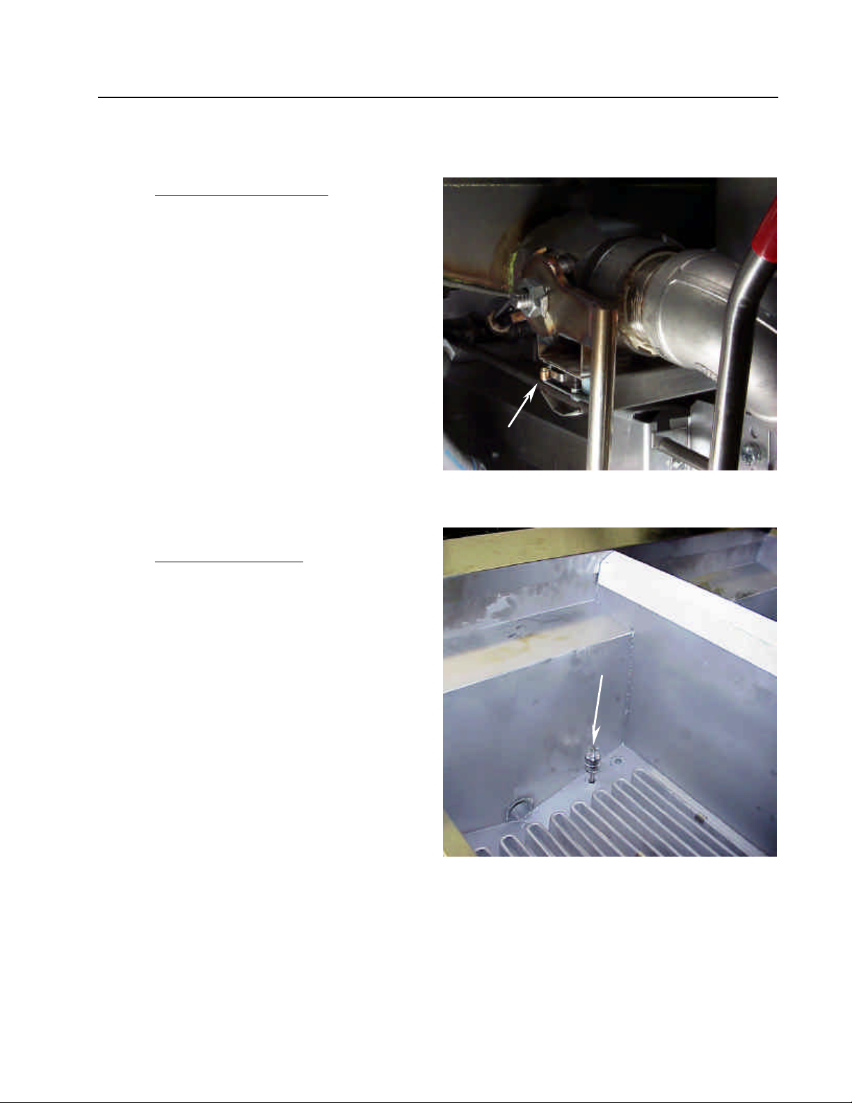
2. Drain Valve Microswitch: The computer
will display Drain Open when the
drain valve is opened. The computer
will lockout and prevent any cooking
operation until the "EXIT/COOL
FILTER" button is pressed.
3. Float Safety Switch: Located in the
frypot. Designed as a safety switch, it
prevents the computer from calling for
heat until the oil level rises above the
heating elements.
Drain valve microswitch location.
Float safety switch location.
3-5
Page 17
KSCFH18E COOL ZONE SERIES ELECTRIC FRYERS
CHAPTER 3: INSTALLATION INSTRUCTIONS
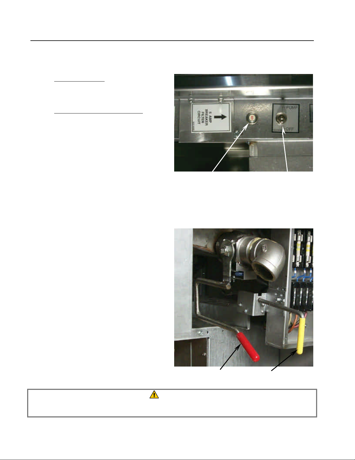
3.5 Operating Switches (cont.)
4. Filter Pump Reset: Located under the left
control panel of the fryer battery. This
switch resets the UFF filter pump motor.
5. Manual Filter Override Switch: Located
under the left fryer control panel of the
fryer battery. This toggle switch allows
the operator to manually operate the UFF
filter if a problem develops with the auto
functions.
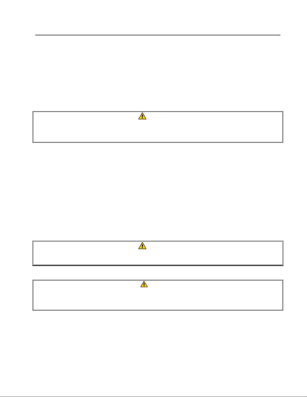
3.6 Drain and Oil-Return Handles
1. Drain Valve Handle (Red). Pull to open.
The drain valve handle should be closed
at all times except when draining and/or
filtering the fryer.
2. Oil Return Valve Handle (Yellow). Pull
the oil return valve handle to open the oil
return valve for the frypot being filtered.
The filter pump activates when this
handle is pulled. Pull the yellow handle
only when filtering. Pushing the yellow
handle in closes the oil return valve and
deactivates the pump motor.
Filter pump reset switch
Manual filter override switch
Drain valve handle.
Oil return valve handle.
WARNING
If the filter pump safety switch repeatedly trips, do not continue to reset. A potential
safety hazard exists. Contact an authorized service technician for troubleshooting.
3-6
Page 18
KSCFH18E COOL ZONE SERIES ELECTRIC FRYERS
CHAPTER 3: INSTALLATION INSTRUCTIONS
3.7 Initial Cleaning Before Startup
New units are wiped clean with solvents at the factory to remove any visible signs of dirt, oil, grease,
etc., remaining from the manufacturing process, then coated lightly with oil. Wash thoroughly with
hot, soapy water to remove any film residue and dust or debris before food preparation, then rinse
out and wipe dry. Wash also any accessories shipped with the unit. Close the drain-valve
completely and remove the crumb screen. Make sure the screws holding the temperature probe onto
the heating elements are tight.
WARNING
All droplets of water must be removed from the frypot before filling with shortening.
Failure to do so will cause splattering of hot shortening and could cause injury to the
operator.
3.8 Final Preparation
A. The KSCFH18E frypot shortening capacity is approximately 90 pounds (40.5Kg).
B. Ensure fryer power switches are "OFF".
C. Ensure the tilt heating-elements are in the "down" position.
D. Liquid shortening (cooking oil): Fill the fryer to the lower OIL LEVEL line on the back of the
frypot. Replace the basket support screen.
WARNING
Never operate fryer without enough cooking compound or water in the frypot to
cover the heating elements.
DANGER
NEVER set a complete block of solid shortening on top of heating elements. To do
so will damage the elements and increase the potential for flash-point shortening
temperatures and subsequent fire.
E. Solid shortening: Either pre-melt solid shortening on another appliance first or cut into small
pieces and pack tightly into the cool zone (bottom) of the frypot (with the heating elements in the
"up" position and OFF). Lower the heating elements and continue to pack the shortening, taking
care not to disturb the temperature probe (on heating elements) or the high-limit (mounted in
frypot). Ensure the float switch is in the "up" position prior to packing solid shortening.
3-7
Page 19

KSCFH18E COOL ZONE SERIES ELECTRIC FRYERS
CHAPTER 3: INSTALLATION INSTRUCTIONS
3.8 Final Preparation (cont.)
Note: If the float switch is blocked in "down position" with solid shortening, the fryer will not
operate. Always ensure that the float switch is in the "up" position prior to packing solid
shortening into frypot.
F. KFC-1 Cooking Computer: Turn
computer on (this turns the fryer on
also). The computer will run the
fryer through the melt cycle to melt
the shortening. As the fryer heating
elements cycle on and off to melt
the shortening, the heat icons
located on either side of the KFC-1
product buttons will cycle on and
off. The computer will display
"LOw" until the shortening reaches
255°F (124°C).
At 255°F (124°C), the computer will display actual temperature until setpoint temperature has
been reached. When the fryer comes out of melt cycle, the fryer will go into continuous heat
mode until the setpoint temperature is reached. When the computer calls for heat, heat icons will
light while the heating elements are energized. At setpoint temperature, the computer will
display "DROP".
G. After shortening reaches the setpoint temperature, let the heating elements cycle at least four
times, then insert a good thermometer or pyrometer near the temperature sensing probe
approximately 3 inches (7.6 cm) into the shortening. When the heating elements just cycle ON
after the fourth time, the thermometer should read within ? 5°F (? 2°C) of the computer
temperature setting.
H. When the frypot is filled and the shortening melted, replace the basket support-screen over the
heating elements.
Heat Icon Indicators
Product Buttons
DANGER
Always wear oil-proof, insulated gloves when working with the fryer filled with HOT
SHORTENING.
Always drain HOT SHORTENING into a metal container. HOT SHORTENING can melt
plastic buckets and crack glass containers.
3-8
Page 20

KSCFH18E COOL ZONE SERIES ELECTRIC FRYERS
CHAPTER 4: DAILY OPERATION
4.1 Opening
1. At opening time, always visually check that the computer is "OFF".
4.2 General Use
1. For consistent quality product, convenience and long-term savings, use a high-quality liquid
shortening.
2. If using solid shortening, never melt a block of shortening by setting it whole in the fryer
vessel.
3. Although 350°F (177°C) is the recommended temperature for most cooking operations, set
the fryer at the lowest possible temperature which produces a high quality end product while
ensuring maximum life for your shortening.
4.3 Start-up Procedures
1. If fryer is empty, pour enough liquid shortening into the frypot to fill to the bottom OIL
LEVEL line scribed on the rear wall. If solid shortening is to be used, melt the shortening
following procedures in Section 3.8, Final Preparation.
2. KFC-1 Cooking Computer:
Turn the computer "ON"
and select cooking program
as described in the KFC-1
Cooking Computer User’s
manual.
4.4 Filtering
1. The KFC-1 Computer must remain ON during filter operations to function properly.
2. Filter the shortening at least once daily or more frequently if cooking is heavy. This assures
the longest life possible for the shortening, a better taste to the food being prepared and
minimizes flavors being transferred from batch to batch.
ON/OFF Buttons
4-1
Page 21

KSCFH18E COOL ZONE SERIES ELECTRIC FRYERS
CHAPTER 4: DAILY OPERATION
4.4 Filtering (cont.)
1. If using solid shortening, clear return lines before turning off the filter motor by allowing the
pump to run for approximately 10-15 seconds once air bubbles appear in the frypot from the
oil return line. Failure to do so will allow solid shortening to cool, solidify and clog the
lines.
See Chapter 6 for detailed filtration procedures.
4.5 Closing
1. When closing at night, filter shortening in all fryers and drain the filter lines. Cover the
open tanks of oil. Turn the computer "OFF".
4.6 Shutdown
1. When shutting down for periods longer than overnight, drain shortening and clean the frypot
thoroughly. Either discard the shortening or return it filtered to the frypot and then cover it.
Turn the computer "OFF".
4-2
Page 22

KSCFH18E COOL ZONE SERIES ELECTRIC FRYERS
CHAPTER 5: PREVENTATIVE MAINTENANCE
5.1 General
Well-maintained equipment operates more efficiently and lasts longer. Keep the fryer clean during
the working day and thoroughly clean at the end of each day.
5.2 Daily
Wash all removable parts. Clean all exterior surfaces of the body. Do not use cleansers, steel wool,
or any other abrasive material on stainless steel. Filter the oil/shortening and replace if necessary.
Filter oil/shortening more often under heavy use conditions (i.e. heavily breaded products).
WARNING
Water MUST NOT be allowed to drain into the filter pan or filter system. Irreversible
damage will result if water is allowed into the system, and all applicable warranties
will be voided.
5.3 Weekly
Completely drain the frypot into either the filter or a steel container. Do not use a plastic bucket or
glass container.
Clean the frypot with a good grade of cleaner or hot water and a strong detergent.
Close the drain valve and refill with either the cleaning solution or water and detergent.
Scrub frypot walls and heating elements. Drain frypot and rinse in clear water.
Once cleaning is completed, drain, rinse, and dry thoroughly.
Refill with shortening as directed in Section 3.8 of this manual.
DANGER
All droplets of water must be removed from the frypot before filling with shortening.
Failure to do so will cause splattering of hot shortening and could cause injury to the
operator.
5-1
Page 23

KSCFH18E COOL ZONE SERIES ELECTRIC FRYERS
CHAPTER 5: PREVENTATIVE MAINTENANCE
5.4 Periodic/Annual
Frymaster recommends that the fryer be inspected annually by a Factory Authorized Service
Technician for the following checks and adjustments:
• Inspect the cabinet inside and out, front and rear for excessive oil build-up and/or oil migration.
• Verify that the heating element wires are in good condition and that leads have no visible fraying
or insulation damage and that they are free of oil migration build-up.
• Verify that heating elements are in good condition with no carbon/caramelized oil build-up.
Inspect the elements for signs of extensive dry-firing.
• Verify that the tilt mechanism is working properly when lifting and lowering elements, and that
the element wires are not binding and/or chafing.
• Verify the heating-element amp-draw is within the allowed range as indicated on the appliance’s
rating plate.
• Verify that the temperature and high-limit probes are properly connected, tightened and
functioning properly, and that mounting hardware and probe guard are present and properly
installed.
• Verify that component box and contactor box components (i.e. computer/controller, relays,
interface boards, transformers, contactors, etc.) are in good condition and free from oil migration
build-up and other debris.
• Verify that component box and contactor box wiring connections are tight and that wiring is in
good condition.
• Verify that all safety features (i.e. contactor shields, drain safety switches, reset switches, etc.)
are present and functioning properly.
• Verify that the frypot/cookpot is in good condition and free of leaks and that the frypot/cookpot
insulation is in serviceable condition.
• Verify that all wiring harnesses and connections are tight and in good condition.
Built-in Filtration:
• Inspect all oil-return and drain lines for leaks and verify that all connections are tight.
• Inspect the filter pan for leaks and cleanliness. If there is a large accumulation of crumbs in the
crumb basket, advise the owner/operator that the crumb basket should be emptied into a fireproof
container and cleaned daily.
• Verify that all O-rings and seals (including those on the Power Shower and on quick-disconnect
fittings) are present and in good condition. Replace o-rings and seals if worn or damaged.
5-2
Page 24

KSCFH18E COOL ZONE SERIES ELECTRIC FRYERS
CHAPTER 5: PREVENTATIVE MAINTENANCE
5.4 Periodic/ Annual (cont.)
• Check filtration system integrity as follows:
− With the filter pan empty, place each oil return handle, one at a time, in the ON position.
Verify that the pump activates and that bubbles appear in the cooking oil/shortening (or that
gurgling is heard from the Power Shower port) of the associated frypot.
− Close all oil return valves (i.e., place all oil return handles in the OFF position). Verify
proper functioning of each oil return valve by activating the filter pump using the lever on
one of the oil return handle microswitches. No air bubbles should be visible in any frypot (or
no gurgling should be heard from the Power Shower ports).
− Verify that the filter pan is properly prepared for filtering, then drain a frypot of oil heated to
350°F (177°C) into the filter pan and close the frypot drain valve. Place the oil return handle
in the ON position. Allow all cooking oil/shortening to return to the frypot (indicated by
bubbles in the cooking oil/shortening or, on units with Power Showers, cessation of oil flow
from the Power Shower). Return the oil return handle to the OFF position. The frypot should
refill in no more than 2 minutes and 30 seconds.
To ensure good fryer health and a safe environment, the fryer should be checked and adjusted
periodically by qualified service personnel as part of a regular kitchen maintenance program.
5.5 Stainless Steel
All stainless steel fryer outer parts should be wiped regularly with hot, soapy water during the day
and with a liquid cleaner designed for this material at the end of each day.
Do not use steel wool, abrasive cloths, cleansers or powders!
Do not use a metal knife, spatula or any other metal tool to scrape stainless steel! Scratches are
almost impossible to remove.
If it is necessary to scrape the stainless steel to remove any encrusted materials, soak the area first to
loosen the material, then use a wood or nylon scraper only.
5-3
Page 25

KSCFH18E COOL ZONE SERIES ELECTRIC FRYERS
CHAPTER 6: UNDER FRYER FILTER (UFF) FILTRATION
6.1 General
WARNING
The on-site supervisor is responsible for ensuring that operators are made aware of
the inherent hazards of operating a hot oil filtering system, particularly the aspects
of oil filtration, draining and cleaning procedures.
The KSCFH18E is equipped with the Under Fryer Filter system (UFF). The shortening should be
filtered at least daily or even more frequently if cooking is heavy. This ensures the longest life
possible for the shortening, gives better taste to the food being prepared, and minimizes flavors
being transferred from batch to batch.
To conduct filter operations with the KFC-1 Cooking Computer installed on the fryer,
ALWAYS leave the computer ON when filtering. The computer must sense the drain valves
opening and closing in order to allow fryer operation.
For consistent product quality, convenience and long-term savings, use a high-quality liquid
shortening or vegetable oil.
If using solid shortening, always ensure the return lines are clear before turning off the filter pump.
Hang any flexible lines up to drain, as solid shortening will solidify as it cools and clog the lines.
6.2 Filter Preparation
Assemble tools to be used for filtering. These are supplied with the filter starter kit:
• Frypot Brush - used to clean frypot sides, heating elements, and to dislodge sediment during
filtration or shortening/oil change.
• Clean-Out Rod - used to dislodge heavy debris in the drain tube (when needed).
• Filter Powder.
• Filter Paper.
The following tools are not required, but are recommended to make the filtering task easier.
• Measuring Cup - used to measure filter powder.
• Stainless Steel Crumb Scoop – for removing large debris from shortening/oil prior to
filtering.
Note: Always wear oil-resistant, insulated gloves and/or protective gear when working with
hot oil.
6-1
Page 26

KSCFH18E COOL ZONE SERIES ELECTRIC FRYERS
water, rinse, then dry thoroughly.
CHAPTER 6: UNDER FRYER FILTER (UFF) FILTRATION
6.2 Filter Preparation (cont.)
1. Put on protective gear/gloves. Pull the filter
pan out from filter cabinet. Remove covers.
Pull the filter pan from the fryer and remove
covers.
2. Place drip pan under male filter pan
connection.
3. Remove the crumb screen. Wash the screen
in hot, soapy water, rinse, then dry
thoroughly.
Proper drip pan placement.
Remove crumb screen. If crumbs are present in
the crumb screen, empty the screen into a
fireproof container. Wash the screen in hot, soapy
6-2
Page 27

KSCFH18E COOL ZONE SERIES ELECTRIC FRYERS
CHAPTER 6: UNDER FRYER FILTER (UFF) FILTRATION
6.2 Filter Preparation (cont.)
4. Unlatch and remove the hold-down ring.
Removing hold-down ring.
5. Remove and discard old filter paper sheet
from the filter pan.
6. Remove the filter screen from the bottom of
the pan.
Remove and discard old filter paper.
Remove filter screen from filter pan.
6-3
Page 28

KSCFH18E COOL ZONE SERIES ELECTRIC FRYERS
Vent hole location on pickup tube.
CHAPTER 6: UNDER FRYER FILTER (UFF) FILTRATION
6.2 Filter Preparation (cont.)
7. Thoroughly clean pan and all pan
components as described for the crumb
screen (Step 3).
Clean filter pan and all pan components. Ensure
all parts are thoroughly dried before reassembly.
8. Inspect pickup tube and ensure vent hole is
open and free of shortening/debris.
9. Replace filter screen, then place one sheet of
filter paper in the bottom of the filter pan.
The filter screen must be installed prior to
filter paper placement, or the filter won’t
operate correctly.
Proper filter paper placement.
6-4
Page 29

KSCFH18E COOL ZONE SERIES ELECTRIC FRYERS
CHAPTER 6: UNDER FRYER FILTER (UFF) FILTRATION
6.2 Filter Preparation (cont.)
10. Reinstall and latch the hold down ring into
position. Ensure filter paper is properly
aligned under hold-down ring.
11. Sprinkle 1-cup (8 ounces/227 grams) evenly
over the paper.
Locking latches on hold-down ring.
12. Replace the crumb screen. Ensure crumb
screen is kept clean throughout the workday.
Use a measuring cup or scoop to evenly distribute
filter powder over the filter sheet.
Properly assembled filter pan, ready for use.
6-5
Page 30

KSCFH18E COOL ZONE SERIES ELECTRIC FRYERS
CHAPTER 6: UNDER FRYER FILTER (UFF) FILTRATION
6.2 Filter Preparation (cont.)
13. Return pan covers to the filter pan.
Pan covers properly placed.
14. Return filter pan to fryer cabinet, ensuring
that the two drainpipe extensions are directly
over opening in filter pan cover.
Pushing filter pan back into cabinet. Filter is ready
for operation.
6-6
Page 31

KSCFH18E COOL ZONE SERIES ELECTRIC FRYERS
CHAPTER 6: UNDER FRYER FILTER (UFF) FILTRATION
6.3 UFF Filter Operations
DANGER
Draining and filtering of cooking oil or shortening must be accomplished with care to
avoid the possibility of a serious burn caused by careless handling. The oil to be
filtered is at or near 350°F (177°C). Ensure all hoses are connected properly and
drain handles are in their proper position before operating any switches or valves.
Wear all appropriate safety equipment when draining and filtering cooking oil or
shortening.
DANGER
NEVER attempt to drain cooking oil or shortening from the fryer with the elements
energized! Doing so will cause irreparable damage to the elements and may cause a
flash fire. Doing so will also void the Frymaster warranty.
WARNING
Drawings and photos used in this manual are intended to illustrate operational,
cleaning and technical procedures and may not conform to on-site management
operational procedures.
DANGER
The crumb tray in fryers equipped with a filter system must be emptied into a
fireproof container at the end of frying operations each day. Some food particles can
spontaneously combust if left soaking in certain shortening material.
DANGER
Do not drain more than one frypot at a time into the built-in filtration unit to avoid
overflow and spillage of hot oil/shortening.
DANGER
When draining oil/shortening into a disposal unit or portable filter unit, do not fill
above the maximum fill line located on the container.
6.3.1 General Overview
The filter pump is turned on only after the shortening/oil is brought to operating temperature and
drained into the prepared filter pan. The filter motor is then engaged and oil is drawn through filter
paper and pumped back into the frypot. The frypot’s drain remains open during the filtering process.
Allow the oil to cycle through the filter paper (use KFC approved filtering procedure). At the end of
the prescribed filtering period, close the drain valve and allow the pump to fill the frypot to the top
OIL LEVEL line. Leave the pump running for 10-15 seconds after bubbles appear in the frypot to
ensure all shortening/oil is pumped from the drain pan and the lines.
6-7
Page 32

KSCFH18E COOL ZONE SERIES ELECTRIC FRYERS
CHAPTER 6: UNDER FRYER FILTER (UFF) FILTRATION
6.3.2 Filter Operation
1. Ensure the filter pan assembly is prepared as described in Section 6.2- Filter Preparation.
Leave the computer ON before, during, and after the filtering process (use KFC approved
filtering procedure).
2. Remove fry baskets from frypot. Prior to
filtering, skim any large debris from the
shortening/oil. Use extreme caution, as
shortening/oil is at or near operating
temperature [~350°F (~177°C)].
3. After ensuring the filter pan is correctly
positioned under the drain tubes, pull the red
handle to drain the frypot into the filter pan.
Drain ONLY one frypot at a time. The filter
pan is designed to hold the contents of one
frypot only.
DANGER
NEVER attempt to clear a clogged
drain valve from the front of the valve!
Hot oil or shortening will rush out
creating the potential for severe burns.
DO NOT hammer on the drain valve
with the clean-out rod or other objects.
Damage to the ball inside will result in
leaks and will void the Frymaster
warranty.
Prior to filtering, skim any large debris from oil in
frypot.
Pull the red handle to open the drain valve.
6-8
Page 33

KSCFH18E COOL ZONE SERIES ELECTRIC FRYERS
CHAPTER 6: UNDER FRYER FILTER (UFF) FILTRATION
6.3.2 Filter Operation (cont.)
4. After all oil/shortening has drained from the
frypot into the filter pan, pull the yellow
handle to open the oil return lines and
activate the filter pump.
Pull the yellow handle to open the oil return valve
and activate the filter pump.
5. Oil will begin to pump from the filter pan
into the frypot. Allow the oil to circulate for
a prescribed time period (use KFC approved
filtering procedure) to remove suspended
particles (process known as "polishing"). If
the frypot sides and bottom have sediment
deposits, lift the heating elements and clean
the frypot with the cleaning brush included
with the fryer.
6. At the end of the filter cycle, close the drain
valve (push the red handle until it stops) and
allow the fryer to refill (see this section, Step
#3 for additional reference). The heating
elements will energize when the float safety
switch rises to a safe level with the oil.
Allow the shortening/oil to circulate the prescribed
time period to ensure all sediment and suspended
particles are removed.
Frypot refilling with filtered shortening/oil.
6-9
Page 34

KSCFH18E COOL ZONE SERIES ELECTRIC FRYERS
CHAPTER 6: UNDER FRYER FILTER (UFF) FILTRATION
6.3.2 Filter Operation (cont.)
7. After all oil is pumped back into the frypot,
bubbles will form, indicating air in the oil
return lines. Allow the oil to bubble for 1015 seconds to ensure all shortening/oil is
evacuated from the return lines. Push the
yellow handle to close the oil return valve
and deactivate the filter pump (see this
section, Step #4 for additional reference).
Allow the shortening/oil to bubble for 10-15
seconds to ensure evacuation of all shortening/oil
in the return lines.
8. Allow the oil to come to operating
temperature. If the oil level is low, add oil
until the level is at the top OIL LEVEL line.
Remember, the oil is at operating
temperature.
9. Do not allow crumbs to accumulate in the
crumb tray. The crumb tray MUST be
emptied into a fireproof container at the end
of frying operations EACH day.
Add oil/shortening until the oil level is at the top
OIL LEVEL line. DO NOT OVERFILL THE
FRYPOT.
Empty contents of the crumb screen into a
fireproof container immediately after filtering is
complete.
6-10
Page 35

KSCFH18E COOL ZONE SERIES ELECTRIC FRYERS
CHAPTER 7: TROUBLESHOOTING
7.1 Introduction
This section provides an easy reference guide to some of the common problems that may occur
during the operation of this equipment. The troubleshooting guides that follow are intended to help
correct, or at least accurately diagnose, problems with this equipment. Although the chapter covers
the most common problems reported, you may encounter problems that are not covered. In such
instances, the Frymaster/Dean Technical Service staff will make every effort to help you identify
and resolve the problem.
When troubleshooting a problem, always use a process of elimination starting with the simplest
solution and working through to the most complex. Never overlook the obvious – anyone can forget
to plug in a cord or fail to close a valve completely. Most importantly, always try to establish a clear
idea of why a problem has occurred. Part of any corrective action involves taking steps to ensure
that it doesn’t happen again. If a controller malfunctions because of a poor connection, check all
other connections, too. If a fuse continues to blow, find out why. Always keep in mind that the
failure of a small component may often be indicative of potential failure or incorrect functioning of a
more important component or system.
Before calling a service agent or the Frymaster/Dean HOTLINE (1-800-551-8633):
• Verify that electrical cords are plugged in and that circuit breakers are on.
• Verify that frypot drain valves are fully closed.
• Verify that frypot float safety switch is not stuck in the "down" position.
DANGER
Hot cooking oil/shortening will cause severe burns. Never attempt to move this
appliance when filled with hot cooking oil/shortening or to transfer hot cooking
oil/shortening from one container to another.
DANGER
The equipment should be unplugged when servicing, except when electrical circuit
tests are required. Use extreme care when performing such tests.
This appliance may have more than one electrical power supply connection point.
Disconnect all power cords before servicing.
Inspection, testing, and repair of electrical equipment should be performed only by
qualified service personnel.
7-1
Page 36

KSCFH18E COOL ZONE SERIES ELECTRIC FRYERS
CHAPTER 7: TROUBLESHOOTING
7.2 Fryer Troubleshooting
Computer fails to turn "ON"
7.2.1
when ON/OFF button is
pressed.
1. Check wall circuit breakers. Reset if
necessary.
2. Check fryer connection to external
power source.
3. Disconnect fryer from power supply.
4. Check 20 amp fuses and replace if
necessary (see photo at left).
5. Power surge/outage may have
temporarily locked out computer.
6. Reconnect power to fryer. Press
computer ON/OFF button "ON".
7. If computer fails to come "ON",
20 amp fuses located in the upper-left fryer
cabinet interior of each fryer.
contact an authorized service agent
for service.
7-2
Page 37

KSCFH18E COOL ZONE SERIES ELECTRIC FRYERS
CHAPTER 7: TROUBLESHOOTING
8.2 Fryer Troubleshooting (cont.)
7.2.2
Actual frypot temperature
differs from computer
setpoint temperature.
7.2 Fryer Troubleshooting (cont.)
1. Turn fryer "ON".
2. Select a product number and allow the
fryer to heat for approximately 30
minutes to stabilize shortening
temperature.
3. Place a thermometer within 1-inch (2.5-
cm) of the temperature probe mounted
on the heating elements.
4. Press the computer temperature button
to check frypot temperature. Press the
computer temperature button twice to
view setpoint temperature for the
product number chosen.
5. The thermometer temperature should be
within ±10°F (±5°C) of the computer
display temperature. If the results are:
Yes- System is maintaining temperature
properly.
No- The computer probe circuit may be
faulty.
7.2.2
(cont.)
Actual frypot temperature
differs from computer
setpoint temperature.
6. Contact your authorized Frymaster
service agent if any of the following
occurs during this test:
a. Computer probe circuit is suspect.
7-3
Page 38

KSCFH18E COOL ZONE SERIES ELECTRIC FRYERS
CHAPTER 7: TROUBLESHOOTING
b. During test, computer fails to call
for heat.
c. Actual frypot temperature is more
than ±10°F (±5°C) of desired
setpoint or computer probemeasured actual temperature.
d. Computer measured actual
temperature differs from setpoint
temperature by more than ±10°F
(±5°C) after shortening has
stabilized per step #2.
Temperature Probe
High-limit
7-4
Page 39

KSCFH18E COOL ZONE SERIES ELECTRIC FRYERS
CHAPTER 7: TROUBLESHOOTING
7.2 Fryer Troubleshooting (cont.)
Computer is ON, but the
7.2.3
7.2.4
heating elements fail to
heat.
DRAIN OPEN message
remains after closing drain
valve.
1. Ensure float safety switch is not stuck in
"down" position. Replace float safety
switch if defective.
2. If computer displays HELP, check
high-limit thermostat (located on right
back frypot side). Replace if defective.
1. Computer was turned OFF while
draining frypot.
2. Close drain valve. Turn computer OFF
and then ON. Computer display will
read ON.
3. Open drain valve for at least 30 seconds.
Computer display will read DRAIN
OPEN.
4. Close drain valve. Computer display
will read FILL.
5. Fill frypot with shortening. Press
EXIT/COOL FILTER when ready to
cook.
6. If computer message DRAIN OPEN
remains after steps 1-4, contact
authorized Frymaster service agent.
a. Drain microswitch may be faulty.
b. Drain circuit may be suspect.
c. Computer may be suspect.
7-5
Page 40

KSCFH18E COOL ZONE SERIES ELECTRIC FRYERS
CHAPTER 7: TROUBLESHOOTING
7.3 Filtration System Troubleshooting
y Return valve not fully open.
y Tripped circuit breaker.
Pump won't
start
y Incorrect or no line voltage.
y Failed return microswitch.
y Allow motor to cool for at least 45 minutes and then
press thermal overload switch on motor.
Pump stops
and motor is
cool.
Pump starts
and abruptly
stops
Pumping is
erratic
y Solidified oil or sediment is likely clogging the return
line. Clear line.
y Reset circuit breaker under control panel.
y Verify wiring harness is properly connected; a
damaged harness should be replaced by a FASC.
y Pump is blocked. Call FASC for service.
y Filter pan suction tube is blocked. Use a thin,
flexible wire to unc log.
y Motor or 24 VAC transformer failed; call for service.
y Verify O-ring on pan outlet is present and in good
condition.
y Verify paper and screen have been properly
installed.
Oil not being
returned to
frypot
After filtering,
fryer does not
operate
properly.
y Move filter h andl e to OFF. Allow oil to cool then
empty pan. Verify filter paper is clean and properly
installed. Refill pan and restart process.
y Verify drain valve is fully closed.
7-6
Page 41

KSCFH18E COOL ZONE SERIES ELECTRIC FRYERS
CHAPTER 7: TROUBLESHOOTING
7.4 Wiring Diagrams
7.4.1 KSCFH218E Fryer Wiring Diagram
HEATING
ELEMENT
67C
67C
L3
66C
66C
L2
CYCLING
65C
CONTACTOR
65C
L1
68C
70C
65432
6
54321
9
3
6
2
8
5
1
7
4
1
7
4
2
8
5
9
6
3
65C
66C
67C
69C
70C
68C
65C
69C
66C
1
4
5
6
67C
2
3
6
3
2
5
1
4
HEATING
ELEMENT
1
11C
27C
26C
L2
70C
69C
70C
69C
56C
CABLE TO REAR
24V
TRANSF
240
220
230
208
COM
3C
5C
9C
COM
240V
208V
12V
TRANSF
67C
67C
66C
66C
65C
65C
CYCLING
CONTACTOR
60A FUSE EACH
FUSE BLOCKS
24C
23C
22C
25C
L1 L3
LATCH CONTACTOR
21C
19C
L2 L3
L1
20C
18C
L2L3
16C
L1
GROUND
L3
L2
17C
L1
BLOCK
TERMINAL
LATCH
CONTACTOR
DELTA
3 PHASE, 3 WIRE
LATCH CONTACTOR
7C ARE ELIMINATED
WIRE 9C GOES TO
HOLDER AND WIRE
NOTE: RIGHT FUSE
24C
23C
8C
22C
27C
26C
25C
TO 12V 9C
53C
68C
68C
8C BLK
TO
FILTER
RED
BLK
7
6C
T1T2
4C
12C
15C
14C
4563
1
GROUND
L3
L2
L1
N
BLOCK
TERMINAL
TRANSFORMER
KSCFH218
4 WIRE WYE
CONNECTION
SPEAKER
44C
DRAIN SWITCH
43C
9
8
2
COMPUTER (BACK)
TILT
SWITCH
WHT
3
2
1
58C
RED
614
5
4
33C
36C
32C
59C
5
2
3
6
OIL
SENSOR
ON ELEMENT
TEMPERATURE
35C
34C
33C
32C
36C
42C
CABLE TO REAR
13C
35C
6
3
1210 11
2
5
897
1
4
34C
654
11 1210
1 2 3
7 89
15 PIN CABLE
42C
BOARD
INTERFACE
110C
2C BLK
8C BLK
41C
1C WHT
7C WHT
FUSE
HOLDER
FUSE
HOLDER
40C
39C
AMP
PINS
HIGH LIMIT
FLOAT
SWITCH
FEMALE
BLK
BLK
AMP
PINS
MALE
8051429A
7-7
Page 42

KSCFH18E COOL ZONE SERIES ELECTRIC FRYERS
CHAPTER 7: TROUBLESHOOTING
7.4.2 Under Fryer Filter (UFF) Wiring Diagram
CIRCUIT
TO RH FRYER
FILTER CIRCUIT
115 V OR 230 V
24V OUT
YEL
YEL
INPUT
BLK
WHT
BLK
BLK
CB
CIRCUIT
BREAKER
115 V - 7 AMP
230 V - 5 AMP
8051366B
SWITCH
MANUAL
BY PASS
ORG
BLK
YEL
BLU
YEL
24V
208V
ORG
BLK
TO 24 VAC
115 VAC OR 230 VAC
RH FRYER TRANFORMER
RH FRYERLH FRYER
NC
NO
24V
COM
YEL #1
2
PUR
RED
YEL #1
NC
NO
24V
COM
PUR
YEL
1
YEL
WHT
ORG
KSCFH18E FILTER CIRCUIT
NC
NO
RED
2
1
T5
OIL RETURN
COM
T4
T8T2T3
MICROSWITCH
P/N 810-2100
MOTOR
T1
LEADS T5 AND T8 ON THE MOTOR
FOR CHANGE OF ROTATI ON INTERCHANGE
PUR
ORG
7-8
WHT
YEL
2
1
11
2
WHT#1
1
NC
2 2
BLK
NO
COM
OIL RETURN
MICRO SWITCH
Page 43

KSCFH18E COOL ZONE SERIES ELECTRIC FRYERS
CHAPTER 7: TROUBLESHOOTING
7.4.3 FAST Wiring Diagram
7-9
8051709 C
Page 44

KSCFH18E COOL ZONE SERIES ELECTRIC FRYERS
CHAPTER 8: PARTS LIST
8.1 KSCFH18E Parts List
For parts and/or components not listed, contact the Frymaster Service Hotline at 1-800-551-8633 or
1-318-865-1711 for additional service and parts information.
8.1.1 Cabinetry and Related Components
32
30
31
29
35
34
24
25
28
18
1
19
3
26
22
21
20
33
14
27
2
23
17
16
15
8
6 7
5
4
9 10
11
12 13
Page 45

KSCFH18E COOL ZONE SERIES ELECTRIC FRYERS
CHAPTER 8: PARTS LIST
8.1.1 Cabinetry and Related Components (cont.)
Item Part # Description
1 201-1299 Side Panel, Painted, LH
2 202-1299 Side Panel, Painted, RH
3 810-0378 Caster, Stationary- 5" Rigid
4 806-5043 Leg
5 823-3180 Support, Channel- Leg/Caster
6 201-1182 Gussets, L/H
7 202-1182 Gussets, R/H
8 200-1675 Lower Hinge Bracket (Door)
9 200-1185 Door Panel, Inner
10 210-1271SP Door Panel, Outer
* 106-0855 Door Assembly
11 810-1105 Magnetic Door Catch
12 810-2105 Handle, Door
* 809-0918 Screw, 10-24 x ½" Slotted Head (Use With 810-2105)
* 809-0191 Washer, ¼ Spring-Lock (Use With 810-2105)
13 200-1301 Door Pin
14 210-1262 Top Cap
15 210-1806 Slide, UFF Filter Pan- Front (Long)
16 210-2128 Slide, UFF Filter Pan- Rear (Short)
17 200-1331 Shield, Heat
18 200-1297 Base, Lower Frame
19 200-1198 Channel, Base
20 200-2134 Plate, Mounting (UFF)
21 200-1611 Base, Upper
22 200-1263 Channel, Bus
23 200-1471 Cover, Access Duct
24 202-1245 Panel, Inner- Right Side
25 201-1245 Panel, Inner- Left Side
26 200-2308 Post, Door
27 210-1278 Guard, Wire- Center
28 200-1254 Guard, Wire- Top
29 200-1255 Guard, Wire- Right Side Center
30 200-1252 Back, Cabinet
31 200-1283 Cover, Back Vent
* 809-0360 Screw, Hex Slotted Head W/Washer- #8 x 3/8"
* Not Illustrated
8-2
Page 46

KSCFH18E COOL ZONE SERIES ELECTRIC FRYERS
CHAPTER 8: PARTS LIST
8.1.1 Cabinetry and Related Components (cont.)
Item Part # Description
32 823-3551 Housing, Tilt
33 210-1288 Joiner Strip
34 810-2092 Hanger, Basket
35 809-0171 Thumbscrew, ¼ x 1-3/8" Nickel-Plated
* Not Illustrated
8.1.2 Component Box, Computers and Related Components
13
1
7
8
14
9
2
6
PUMP
OFF
10
3
4
5
11
12
16
15
18
17
19
8-3
Page 47

KSCFH18E COOL ZONE SERIES ELECTRIC FRYERS
CHAPTER 8: PARTS LIST
8.1.2 Component Box, Computers and Related Components (cont.)
Item Part # Description
1 806-6336 Interface Board, KFC-1
* 106-6671 Interface Board, FAST-Ready
2 807-0979 Transformer, 208-240V, 50/60Hz –12V 20VA
3 807-0680 Transformer, 208-240V, 50/60Hz –24V 20VA
4 807-3611 Relay, 24-Amp
5 807-0884 Contactor, Mercury- 240VAC 50-Amp
6 810-1202 Contactor, Latching- 40-Amp, 3-Pole
7 807-0922 Fuse Holder, Buss Fuse
* 807-2278 Fuse, 20-Amp
8 806-5974SP Sound Device, KFC-1
* 807-4114 Sound Device, FAST-Ready
9 807-3538 Breaker, Circuit- 5 Amp (208/230 VAC)
10 807-3539 Switch, Toggle- Filter Bypass- ON-OFF
11 807-0501 Fuse Block, Buss #2968, 3-Pole
12 807-3610 Power Block– 3-Phase (Delta)
* 807-2465 Power Block– 3-Phase (Wye)
13 823-3458 Wireway Control Panel (Box) Assembly
* 807-0800 Transformer, 120V 50/60 Hz -24V 50VA (Pump Motor Relay)
* 807-0680 Transformer, 208V, 50/60Hz –24V 20VA (Pump Motor Relay)
14 Computer, KFC-1 Electric
* 106-0063 Non-CE
* 106-0065 CE
15 210-1256 Panel, Control, KFC-1
16 210-3018 Panel, Control, FAST-Ready
17 823-2882 Bezel, Computer, KFC-1
18 230-3884 Bezel, Computer, FAST-Ready
19 807-1502 Lamp, Amber, Heating, 24V
* Not Illustrated
8-4
Page 48

KSCFH18E COOL ZONE SERIES ELECTRIC FRYERS
CHAPTER 8: PARTS LIST
8.1.3 Elements and Related Components
5
6
4
3
2
1
18
7
4
9
11
17
16
10
8
12
13
14
15
8-5
19
Page 49

KSCFH18E COOL ZONE SERIES ELECTRIC FRYERS
CHAPTER 8: PARTS LIST
8.1.3 Elements and Related Components (cont.)
Item # Part # Description
1 807-3652 Element- 208V 8.5 kW
* 807-3655 Element- 240V 8.5 kW
* 807-3657 Element- 208V 9.0 kW
* 807-3658 Element- 240V 9.0 kW
* 807-2557 Element- 208V 10.25 kW
* 807-3655 Element- 240V 8.5 kW (USE FOR 220V 7 kW)
* 807-3660 Element- 220V 8.5 kW
* 807-3661 Element- 220V 10.25 kW
* 807-3662 Element- 230V 7 kW
* 807-3663 Element- 230V 8.5 kW
* 807-3664 Element- 230V 10.25 kW
* 807-2637 Element- 240V 10.25 kW
* 807-3660 Element- 220V 8.5 kW (USE FOR 200V 7 kW)
* 807-2137 Connector, Element- Male, 9-Pin
* 807-2135 Connector, Element- Male (High Amp), 6-Pin
* 810-2120 Grid, Mesh- Over Element- Full Vat
2 826-1339 Bushing, .375 x .188" I.D. (Qty:10)
3 826-1330 Screw, 10-32 x 3/8" Slotted Head- SS (Qty: 25)
4 210-1313 Tilt Plate
* 900-5378 Bracket, Tilt Plate Spring
* 809-0358 Turnbuckle, Tilt Plate Spring
* 810-0297 Spring, Tilt Plate
* 200-2932 Cover, Lower Back Wire
5 826-1376 Nut, Keps- 10-32 Hex (Qty: 10)
6 826-1791 Probe, Temperature- 15" (Includes Ty Wrap)
* 807-1068 Connector, 2-Pin
* 809-0567 Ty Wrap, Metal (Probe Lead to Element: 4 Required)
7 910-5022 Bracket, Probe Guard
8 201-1573 Bracket, Element Support- Left Side
9 202-1573 Bracket, Element Support- Right Side
10 816-0214
11 810-0035 Hinge, Tilt- 14" Continuous
Nylon Bar, Tilt Plate Spring Bracket (Use .123 x .379"
Pop Rivet To Attach)
* Not Illustrated
12 910-5459 Support, Back- Full-vat Element
8-6
Page 50

KSCFH18E COOL ZONE SERIES ELECTRIC FRYERS
CHAPTER 8: PARTS LIST
8.1.3 Elements and Related Components (cont.)
Item # Part # Description
13 810-1212 Spring Pin, Heating Element Handle
14 823-2534
15 210-1610 Support, Bottom- Full-vat Element
16 910-2042 Clamp, Element to Support
17 810-1233 Handle, Lift- Full-vat Element
18 809-0518 Screw, 8-32 x 3/8" Hex Washer Slotted
19 806-8035 High-limit Thermostat (Mounts in Frypot)
* Not Illustrated
Support, Front- Full-vat Element (Without Handle and
Spring Pin)
8.1.4 Tilt Safety Switch Components
3
1
2
Item Part Number Description
1 806-6849SP Switch, Tilt Safety
* 809-0874 Ty Wrap, Plastic- 4" (Operating Temperature 265°F)
2 807-1570 Clip, Tilt Switch
3 807-1397 Terminal, Push-On- Fully Insulated
* 809-0250 Nut, Keps- 6-32 Hex
* 809-0096 Screw, 6-32 x 5/8"- Binding, Slotted-Head
* 826-1374 Screw, #10-½ - Hex Washer Head (Qty: 25)
* 809-0766 Nut, SS- 10-32
* Not Illustrated
8-7
Page 51

KSCFH18E COOL ZONE SERIES ELECTRIC FRYERS
CHAPTER 8: PARTS LIST
8.1.5 Frypot and Drain Components
Float-Switch
Location
High-Limit Location
16
1
2
7
3
4
5
10
6
8
9
11
15
14
12
13
17
8-8
Page 52

KSCFH18E COOL ZONE SERIES ELECTRIC FRYERS
CHAPTER 8: PARTS LIST
8.1.5 Frypot and Drain Components (cont.)
Item Part # Description
1 816-0547 Cap, Vinyl- Red
2 823-3224 Handle, Drain Valve
3 200-1257 Retainer, Drain Valve Nut
4 812-0442 Insulation, Microswitch
5 826-1366 Nut, 4-40 Keps Hex With External Tooth (Qty: 25)
6 807-2104 Microswitch, Roller
7 823-3236 Valve, Drain- With Washers, Nut and Bracket
8 813-0687 Nipple, SS- 1-½" x Close
9 823-3221 Elbow With Bracket, Drain- Left
10 823-3222 Elbow With Bracket, Drain- Right
11 823-3456 Drain Pipe- Left
12 823-3358 Drain Pipe- Right
13 809-0123 Screw, 10-32 x ¾" Slotted Head
14 826-1376 Nut, Keps- 10-32 Hex (Qty: 10)
15 210-2311 Clamp, Center- Drain Pipe
16 823-3235SP Frypot, SS- KSCFH18E
17 106-0960SP Switch, Float Safety
8-9
Page 53

KSCFH18E COOL ZONE SERIES ELECTRIC FRYERS
CHAPTER 8: PARTS LIST
8.1.6 Filter Pan, Pump Motor and Related Components
6
25
5
7
24
4
13
22
14
3
2
1
8
9
23
22
21
18
19
20
15
16
17
18
19
11
12
10
8-10
Page 54

KSCFH18E COOL ZONE SERIES ELECTRIC FRYERS
CHAPTER 8: PARTS LIST
8.1.6 Filter Pan, Pump Motor and Related Components (cont.)
Item Part # Description
1 823-3240 Pan, Filter
2 810-2119 Grid, Filter
3 803-0170 Paper, Filter
* 803-0002 Filter Powder
4 823-3201 Ring, Hold-Down (No Handles)
* 823-3202 Handle, Hold-Down Ring
5 823-3204 Crumb Basket
6 823-3241 Lid, Filter Pan- Front
7 210-1295 Lid, Filter Pan- Back
* 810-2105 Handle, Pan Lid, Front and Back- Chrome
* 809-0918 Screw, 10-24 x ½" Slotted (Use With 810-2105)
* 809-0191 Washer, ¼ Spring-Lock (Use With 810-2105)
8 809-0866 Screw, SS- ¼-10 x ½" Phillips Head
9 210-1293 Insert, Mounting Plate- Caster
10 810-2141 Caster, 2"
11 809-0823 Nut, Nylock- ¼-20
12 809-0822 Bolt, ¼-20 x ½" Hex Head
13 813-0679 Plug, SS- 1/8 Square Head
14 810-2100 Motor, Filter Pump
15 810-2098 Pump, Filter- 8GPM
16 Fitting, Oil Suction Start
* 813-0022 Nipple, ½" NPT x Close BM
* 813-0003 Tee, ½" NPT BM
* 813-0156 Plug, Hex Head ½" NPT BM
17 813-0703 Nipple, ½ x 7-¾" NPT BM
18 813-0062 Elbow, ½" x 90° NPT BM
19 813-0265 Nipple, ½ x 2-½" NPT BM
20 813-0173 Union, ½" NPT BM
21 813-0683 Nipple, ½ x 6" NPT BM
22 813-0608 Coupling, Full
23 823-3546 Nipple/Plate Assembly- KFC18E
24 810-0697 Disconnect, Male
* 826-1392 O-Ring, Disconnect (Qty: 5)
25 106-0820SP Drip Cup Assembly
* 803-0209 Brush, Frypot
* Not Illustrated
8-11
Page 55

KSCFH18E COOL ZONE SERIES ELECTRIC FRYERS
8.1.7 Oil Return Components
CHAPTER 8: PARTS LIST
19
3
2
1
17
20
4
5
18
19
17
18
6
26
8
6
17
9 10
6
16
12
7
14
11
14
15
7
7
13
27
21
22
25
24
23
8-12
Page 56

KSCFH18E COOL ZONE SERIES ELECTRIC FRYERS
CHAPTER 8: PARTS LIST
8.1.7 Oil Return Components (cont.)
Item # Part # Description
1 823-3344 Handle, Actuator- Oil Return Valve
2 809-0843 Pin, Cotter- Plated
3 809-0885 Washer, 3/8 x 1 x .083" Type A Plain
4 823-3238 Handle, Oil Return Activate
5 816-0548 Cap, Vinyl- Yellow, Oil Return Handle
6 813-0173 Union, ½" NPT BM
7 813-0022 Nipple, ½" x Close NPT BM
8 813-0634 Elbow, Reducing- ½ x 3/8" x 90° NPT BM
9 813-0644 Nipple, 3/8 x 1-½" NPT BM
10 810-2125 Valve, Ball- Oil Return, 3/8"
11 813-0625 Nipple, 3/8" x Close NPT BM
12 813-0006 Bushing, Reducing- ½ x 3/8" NPT BM
13 813-0706 Elbow, Street- ½" x 90° NPT BM
14 813-0062 Elbow- ½" x 90° NPT BM
15 813-0622 Nipple, ½ x 1-½" NPT BM
16 813-0247 Nipple, ½ x 3-½" NPT BM
17 813-0003 Tee, ½" NPT BM
18 813-0654 Nipple, ½ x 4" NPT BM
19 813-0156 Plug, Pipe- ½" NPT BM
20 813-0672 Nipple, ½ x 8" NPT BM
21 106-0893SP Bracket Assembly- Oil Return Microswitch- RH
22 810-2144 Spacer, Aluminum- ¼ O.D. x 3/8"
23 807-2104 Microswitch, Oil Return
24 809-0846 Screw, 4-40 x 1" Slotted Head
25 826-1366 Nut, 4-40 Keps External Tooth (Qty: 25)
26 200-1341 Bracket, Oil Return Handle
27 826-1371 Screw, #8 x ½" (Qty: 25)
* Not Illustrated
8-13
Page 57

THIS PAGE INTENTIONALLY LEFT BLANK
Page 58

Frymaster, L.L.C., 8700 Line Avenue, Shreveport, Louisiana 71106
TEL 1-318-865-1711 FAX (Parts) 1-318-219-7140 (Tech Support) 1-318-219-7135
PRINTED IN THE UNITED STATES
SERVICE HOTLINE
1-800-551-8633
Price: $10.00
819-5678
August 2002
 Loading...