

Page 1

OPERATOR’S MANUAL
FRYMASTER H52 SERIES
This equipment chapter is to be
installed in the Fryer Section of the
Equipment Manual.
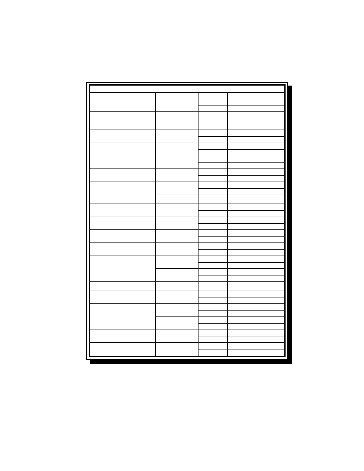
TABLE OF CONTENTS
MANUFACTURED
FRYMASTER, L.L.C.
P.O. BOX 51000
SHREVEPORT, LOUISIANA 71135-1000
PHONE: 1-318-865-1711
TOLL FREE: 1-800-551-8633
1-800-24 FRYER
FAX: 1-318-219-7135
BY
GAS FRYER
FOR YOUR SAFETY
Do Not Store or use gasoline or other
flammable vapors and liquids in the
vicinity of this or any other appliance.
WARRANTY STATEMENT...................................................................................................Page i
INTRODUCTION...................................................................................................................Page 1-1
INSTALLATION INSTRUCTIONS ........................................................................................Page 2-1
OPERATING FRYERS WITH M100B COOKING COMPUTERS.........................................Page 3-1
OPERATING FRYERS WITH THERMOSTAT CONTROLLERS .........................................Page 4-1
FILTERING............................................................................................................................Page 5-1
PREVENTIVE MAINTENANCE AND TROUBLESHOOTING ..............................................Page 6-1
Frymaster, L.L.C. 8700 Line Avenue 71106, 5489 Campus Drive 71129
P.O. Box 51000, Shreveport, Louisiana 71135-1000
TEL 318-865-1711 FAX (Parts) 318-219-7140 (Tech Support) 318-219-7135
PRINTED IN THE UNITED STATES SERVICE HOTLINE 819-5404 02/05
1-800-24-FRYER U.S. $6.00
Page 2

Page 3
CHAPTER 1: INTRODUCTION
1.1 General
Read the instructions in this manual thoroughly before attempting to operate this equipment. This
manual covers all configurations of models MH52 and BIH52 fryers built since December 1995.
Models designated MH52 do not have built-in filtration systems. Models designated BIH52 are
equipped with FootPrint III built-in filtration systems.
H52 Series fryers feature deep cold-zones and easy to clean, open frypots. The fryers are controlled
by multi-product cooking computers or optional thermostat controllers. Fryers in this series come in
full or split-pot arrangements, and can be purchased as single units or grouped in batteries of up to
five fryers.
1.2 Safety Information
Before attempting to operate your unit, read the instructions in this manual thoroughly.
Throughout this manual, you will find notations enclosed in double-bordered boxes similar to the ones
below.
CAUTION boxes contain information about actions or conditions that may cause or result in a
malfunction of your system.
CAUTION
Example of a CAUTION box.
WARNING boxes contain information about actions or conditions that may cause or result in
damage to your system, and which may cause your system to malfunction.
WARNING
Example of a WARNING box.
DANGER boxes contain information about actions or conditions that may cause or result in injury to
personnel, and which may cause damage to your system and/or cause your system to malfunction.
DANGER
Hot cooking oil causes severe burns. Never attempt to move a fryer containing hot
cooking oil or to transfer hot cooking oil from one container to another.
Fryers in this series are equipped with automatic safety features:
1. A high-limit thermostat causes the gas valve to close should the controlling thermostat fail or
computer temperature probe fail.
2. In BIH52 fryers, a safety switch built into the drain valve prevents the gas valve from opening
with the drain valve even partially open.
1-1
Page 4
1.3 Computer Information
This equipment has been tested and found to comply with the limits for a Class A digital device,
pursuant to Part 15 of the FCC rules. While this device is a verified Class A device, it has been shown
to meet the Class B limits. These limits are designed to provide reasonable protection against harmful
interference when the equipment is operated in a commercial environment. This equipment generates,
uses and can radiate radio frequency energy and, if not installed and used in accordance with the
instruction manual, may cause harmful interference to radio communications. Operation of the
equipment in a residential area is likely to cause harmful interference in which case the user will be
required to correct the interference at his own expense.
The user is cautioned that any changes or modifications not expressly approved by the party
responsible for compliance could void the user's authority to operate the equipment.
If necessary, the user should consult the dealer or an experienced radio and television technician for
additional suggestions.
The user may find the following booklet prepared by the Federal Communications Commission
helpful: "How to Identify and Resolve Radio-TV Interference Problems". This booklet is available
from the U.S. Government Printing Office, Washington, DC 20402, Stock No. 004-000-00345-4.
1.4 European Community (CE) Specific Information
The European Community (CE) has established certain specific standards regarding equipment of this
type. Whenever a difference exists between CE and non-CE standards, the information or instructions
concerned are identified by means of shadowed boxes similar to the one below.
CE Standard
Example of box used to distinguish CE and
Non-CE specific information.
1.5 Shipping Damage Claim Procedure
What to do if your equipment arrives damaged:
Please note that this equipment was carefully inspected and packed by skilled personnel before
leaving the factory. The freight company assumes full responsibility for safe delivery upon acceptance
of the equipment.
1. File Claim for Damages Immediately—Regardless of extent of damage.
2. Visible Loss or Damage—Be sure this is noted on the freight bill or express receipt and is signed
by the person making the delivery.
3. Concealed Loss or Damage—If damage is unnoticed until equipment is unpacked, notify Freight
Company or carrier immediately and file a concealed damage claim. This should be done within
15 days of date of delivery. Be sure to retain container for inspection.
1-2
Page 5

1.6 Service Information
McDonald’s store personnel perform routine maintenance. For non-routine maintenance or repairs, or
for service information, contact your local Frymaster Authorized Service Center (FASC). Service
information may also be obtained by calling the Frymaster Technical Services Department (1-80024FRYER). The following information will be needed in order to assist you efficiently:
Model Number_________________________
Serial Number _________________________
Gas Type_____________________________
Nature of the Problem ___________________
____________________________________
____________________________________
RETAIN AND STORE THIS MANUAL IN A SAFE PLACE FOR FUTURE USE.
1-3
Page 6

CHAPTER 2: INSTALLATION INSTRUCTIONS
2.1 General Installation Requirements
NOTE: PROPER INSTALLATION IS ESSENTIAL FOR EFFICIENT, TROUBLE-FREE
OPERATION OF YOUR FRYER. ANY UNAUTHORIZED ALTERATIONS MADE TO THIS
EQUIPMENT WILL VOID THE FRYMASTER WARRANTY.
Upon arrival, inspect the fryer carefully for visible or concealed damage. (See Shipping Damage
Claim Procedure in Chapter 1.)
CLEARANCE AND VENTILATION
The fryer(s) must be installed with a 6” (150 mm) clearance at both sides and back when installed
adjacent to combustible construction; no clearance is required when installed adjacent to noncombustible construction. A minimum of 24” (600 mm) clearance should be provided at the front of the
fryer.
One of the most important considerations of efficient fryer operation is ventilation. Make sure the
fryer is installed so that products of combustion are removed efficiently, and that the kitchen ventilation system does not produce drafts that interfere with proper burner operation.
The fryer flue opening must not be placed close to the intake of the exhaust fan, and the fryer must
never have its flue extended in a “chimney” fashion. An extended flue will change the combustion
characteristics of the fryer, causing longer recovery time. It also frequently causes delayed ignition.
To provide the airflow necessary for good combustion and burner operation, the areas surrounding
the fryer front, sides, and rear must be kept clear and unobstructed.
Fryers must be installed in an area with an adequate air supply and adequate ventilation. Adequate
distances must be maintained from the flue outlet of the fryer to the lower edge of the ventilation
filter bank. Filters should be installed at an angle of 45º. Place a drip tray beneath the lowest edge
of the filter. For U.S. installation, NFPA standard No. 96 states, “A minimum distance of 18 in.
(450 mm) should be maintained between the flue outlet and the lower edge of the grease filter.”
Frymaster recommends that the minimum distance be 24 in. (600 mm) from the flue outlet to the
bottom edge of the filter when the appliance consumes more than 120,000 BTU per hour.
For installations in the United States, information on construction and installation of ventilating
hoods can be found in the NFPA standard cited above. A copy of the standard may be obtained
from the National Fire Protection Association, Battery March Park, Quincy, MA 02269.
Do not attach an apron drainboard to a single fryer. The fryer may become unstable,
tip over, and cause injury. The appliance area must be kept free and clear of com-
DANGER
bustible material at all times.
2-1
Page 7
NATIONAL CODE REQUIREMENTS
The type of gas for which the fryer is equipped is stamped on the data plate attached to the inside of
the fryer door. Connect a fryer stamped “NAT” only to natural gas, those stamped “PRO” only to
propane gas, and those stamped “MFG” only to manufactured gas.
Installation shall be made with a gas connector that complies with national and local codes, and,
where applicable, CE codes. Quick-disconnect devices, if used, shall likewise comply with national,
local, and, if applicable, CE codes.
ELECTRICAL GROUNDING REQUIREMENTS
All electrically operated appliances must be grounded in accordance with all applicable national and
local codes, and, where applicable, CE codes. A wiring diagram is located on the inside of the fryer
door. Refer to the rating plate on the inside of the fryer door for proper voltages.
DANGER
If this appliance is equipped with a three-prong (grounding) plug, it must be plugged
directly into a properly grounded receptacle.
Do not cut or remove the grounding prong from the plug.
DANGER
This equipment requires electrical power for operation.
Place the gas control valve in the OFF position in case of a prolonged power outage.
Do not attempt to use the equipment during a power outage.
FCC COMPLIANCE
The user is cautioned that any changes or modifications to Frymaster computers not expressly approved by the party responsible for compliance could void the user’s authority to operate the equipment.
Frymaster computers have been tested and found to comply with the limits for a Class A digital device, pursuant to Part 15 of the FCC rules. While these devices are verified as Class A devices, they
have been shown to meet the Class B limits. These limits are designed to provide reasonable protection against harmful interference when the equipment is operated in a commercial environment. This
equipment generates, uses, and can radiate radio frequency energy and, if not installed and used in
accordance with the instruction manual, may cause harmful interference to radio communications.
Operation of the equipment in a residential area is likely to cause harmful interference in which case
the user will be required to correct the interference at his own expense.
If necessary, the user should consult the dealer or an experienced radio and television technician for
additional suggestions.
2-2
Page 8

The user may find the booklet “How to Identify and Resolve Radio-TV Interference Problems” helpful. It is prepared by the Federal Communications Commission and is available from the U.S. Government Printing Office, Washington, DC 20402, Stock No. 004-000-00345-4.
2.2 Caster/Leg Installation
Depending upon the specific configuration ordered, your fryer may have been shipped without installed casters or legs. If casters or legs are installed, you may skip this section and proceed to section 2.3, Pre-Connection Preparations.
If your fryer requires the installation of casters/legs, install them in accordance with the instructions included in your accessory package.
2.3 Pre-Connection Preparations
DANGER
Do not connect fryer to gas supply before completing each step
in this section.
After the fryer has been positioned under the fry station exhaust hood, ensure the following has been
accomplished:
1. Adequate means must be provided to limit the movement of fryers without depending upon the
gas line connections. If a flexible gas hose is used, a restraining cable must be connected at all
times when the fryer is in use. The restraining cable and installation instructions are packed with
the flexible hose in the accessories box that was shipped with your unit.
2. Single unit fryers must be stabilized by installing restraining chains on fryers equipped with
casters or anchor straps on fryers equipped with legs. Follow the instructions shipped with the
casters/legs to properly install the chains or straps.
3. Level the fryer, if necessary, by loosening the locking screw on the caster legs and rotating the
leg to increase or decrease the exposed length. Verify that the fryer is at the proper height in the
exhaust hood. Frymaster recommends that the minimum distance from the flue outlet to the bottom edge of the hood be 24 in. (600 mm) when the appliance consumes more than 120,000 BTU
per hour.
4. Test the fryer electrical system:
a. Plug the fryer electrical cord(s) into a grounded electrical receptacle.
b. Place the power switch in the ON position.
• For fryers equipped with thermostat controls, note the illumination of the power light and
the heat light.
• For fryers having computers, note that the display reads LO-TEMP and the heat light
comes on.
• If the store is equipped with a hood interlock system, the hood exhaust fan should be on.
If not, the store hood interlock system is improperly wired and must be corrected.
c. Place the fryer power switch in the OFF position. Verify that the power and heat lights are
out, or that the display is blank.
2-3
Page 9
5. Refer to the data plate on the inside of the fryer door to determine if the fryer burner is configured for the proper type of gas before connecting the fryer quick-disconnect device or piping
from the gas supply line.
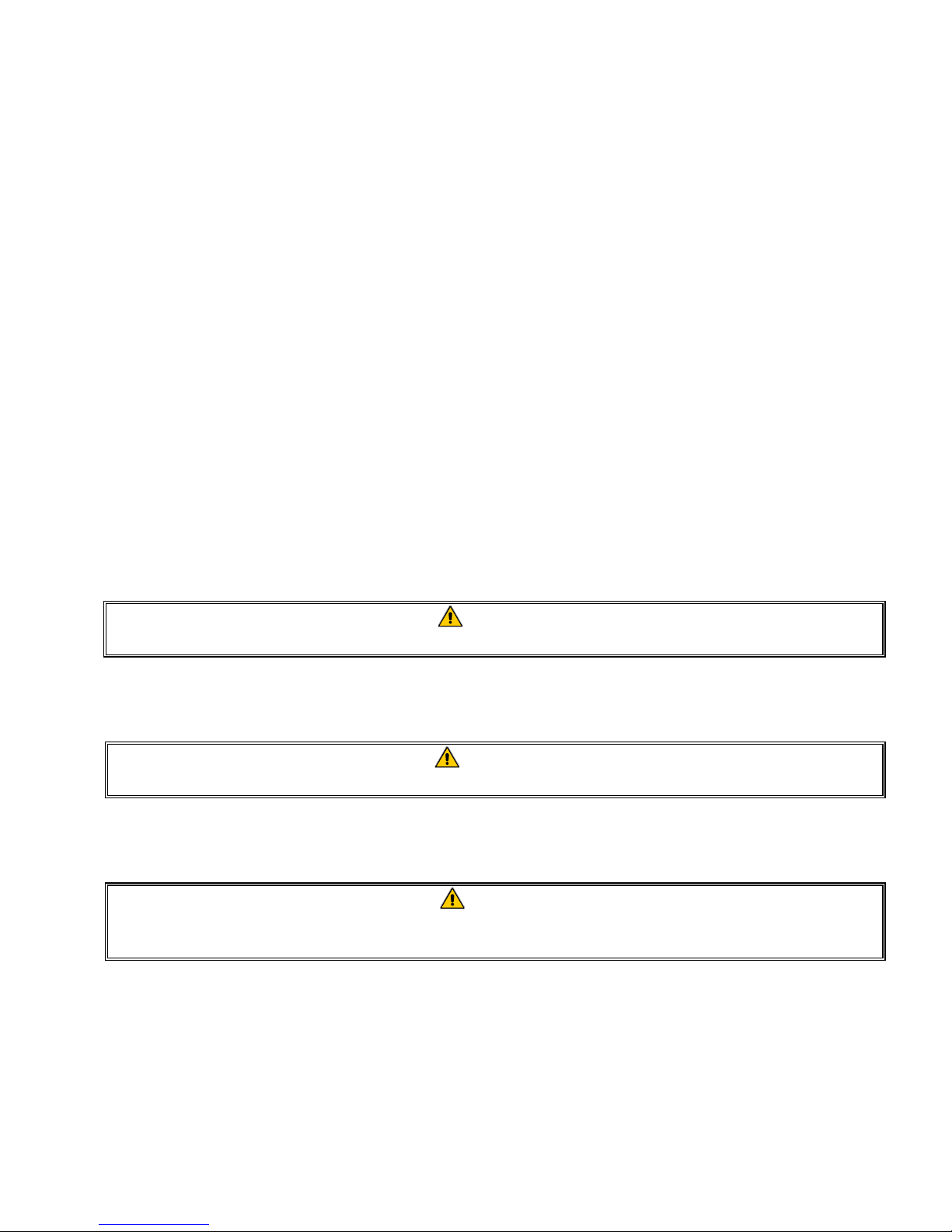
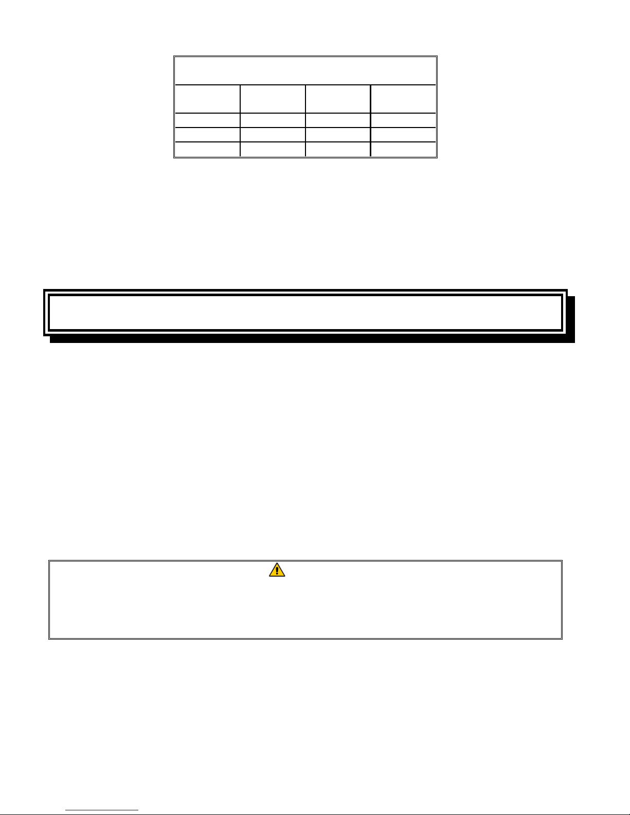
6. Verify the minimum and maximum gas supply pressures for the type of gas to be used in accordance with the accompanying tables.
CE Standard
for Incoming Gas Pressures
for Fryers Manufactured After April 1999
Orifice Diameter
Pressure
Gas
G20 20 2 x 3.40 2 x 3.40 7 mbar 6.5 mbar
G25 20 or 25 2 x 3.40 2 x 3.40 10 mbar 9 mbar
G30 28/30 or 50 2 x 2.05 2 x 2.05 17 mbar 17 mbar
G31 37 or 50 2 x 2.05 2 x 2.05 20 mbar 18.5 mbar
(mbar)
Single
(1)
Vat
Dual
Vat
Regulator Pressure
Single
Vat
(1) mbar = 10.2 mm H2O
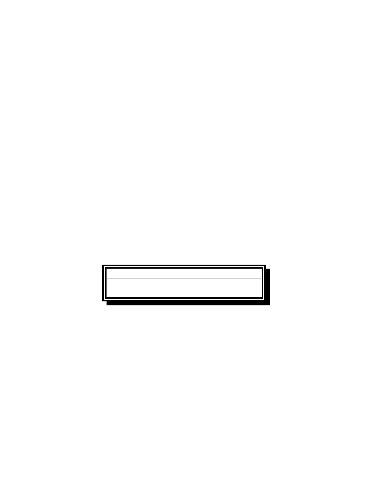
CE Standard
for Incoming Gas Pressures
for Fryers Manufactured Through April 1999
Orifice Diameter
Pressure
Gas
G20 20 2 x 3.40 2 x 3.40 7 mbar 6.5 mbar
G25 20 - 25 2 x 3.40 2 x 3.40 10 mbar 9 mbar
G31 37 - 50 2 x 2.05 2 x 2.05 20.2 mbar 18.5 mbar
(mbar)
Single
(1)
Vat
Dual
Vat
(1) mbar = 10.2 mm H2O
Regulator Pressure
Single
Vat
Dual
Vat
Dual
Vat
7. For fryers equipped with a FootPrint III system (BIH52 models), plug the electrical cord into a
power receptacle behind the fryer.
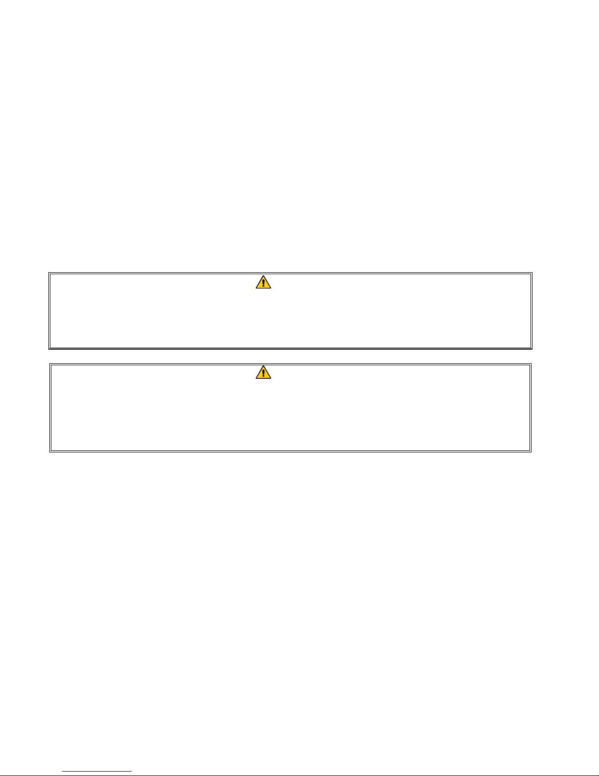
Non-CE Standard
for Incoming Gas Pressures
Gas Minimum Maximum
Natural
LP
6" W.C.
1.49 kPa
14.93 mbar
11" W.C.
2.74 kPa
27.37 mbar
14" W.C.
3.48 kPa
34.84 mbar
14" W.C.
3.48 kPa
34.84 mbar
2-4
Page 10
2.4 Connection to Gas Line
The H52 Series has received the CE mark for the countries and gas categories indicated in the
accompanying table. NOTE: The nominal heat input (Qn) is 21kW except for AT, DE, LU, and for
category 3B/P under 50 mbar, which is 23kW.
CE Approved Gas Categories by Country*
COUNTRIES CATEGORIES GAS PRESSURE (mbar)
AUSTRIA (AT)
BELGIUM (BE)
DENMARK (DK)
FRANCE (FR)
FINLAND (FI)
GERMANY (DE)
GREECE (GR)
ITALY (IT)
IRELAND (IE)
LUXEMBOURG (LU)
NETHERLANDS (NL)
NORWAY (NO)
PORTUGAL (PT)
SPAIN (ES)
SWEDEN (SE)
UNITED KINGDOM (GB)
II
2H3B/P
I
2E(R)B
I
3+
II
2H3B/P
II
2Esi3+
II
2Esi3P
II
2H3B/P
II
2ELL3B/P
I
3P
II
2H3+
II
2H3+
II
2H3+
II
2E3B/P
II
2L3P
II
2L3B/P
I
3B/P
II
2H3+
II
2H3+
II
2H3P
II
2H3B/P
II
2H3+
G20 20
G30, G31 50
G20, G25 20, 25
G30, G31 28-30, 37
G20 20
G30, G31 30
G20, G25 20, 25
G30, G31 28-30, 37
G20, G25 20, 25
G31 50
G20 20
G30, G31 30
G20, G25 20
G30, G31 50
G31 50
G20 20
G30, G31 28-30, 37
G20 20
G30, G31 28-30, 37
G20 20
G30, G31 28-30, 37
G20 20
G30, G31 50
G25 25
G31 50
G25 25
G30, G31 30
G30, G31 30
G20 20
G30, G31 28-30, 37
G20 20
G30, G31 28-30, 37
G20 20
G31 37, 50
G20 20
G30, G31 30
G20 20
G30, G31 28-30, 37
* H152-2 units are not approved for G30 (Butane) gas.
The size of the gas line used for installation is very important. If the line is too small, the gas pressure at the burner manifold will be low. This may cause slow recovery and delayed ignition. Frymaster recommends the incoming gas supply line be a minimum of 1½” (38 mm) in diameter. Refer
to the chart on the following page for the minimum sizes of connection piping.
2-5
Page 11
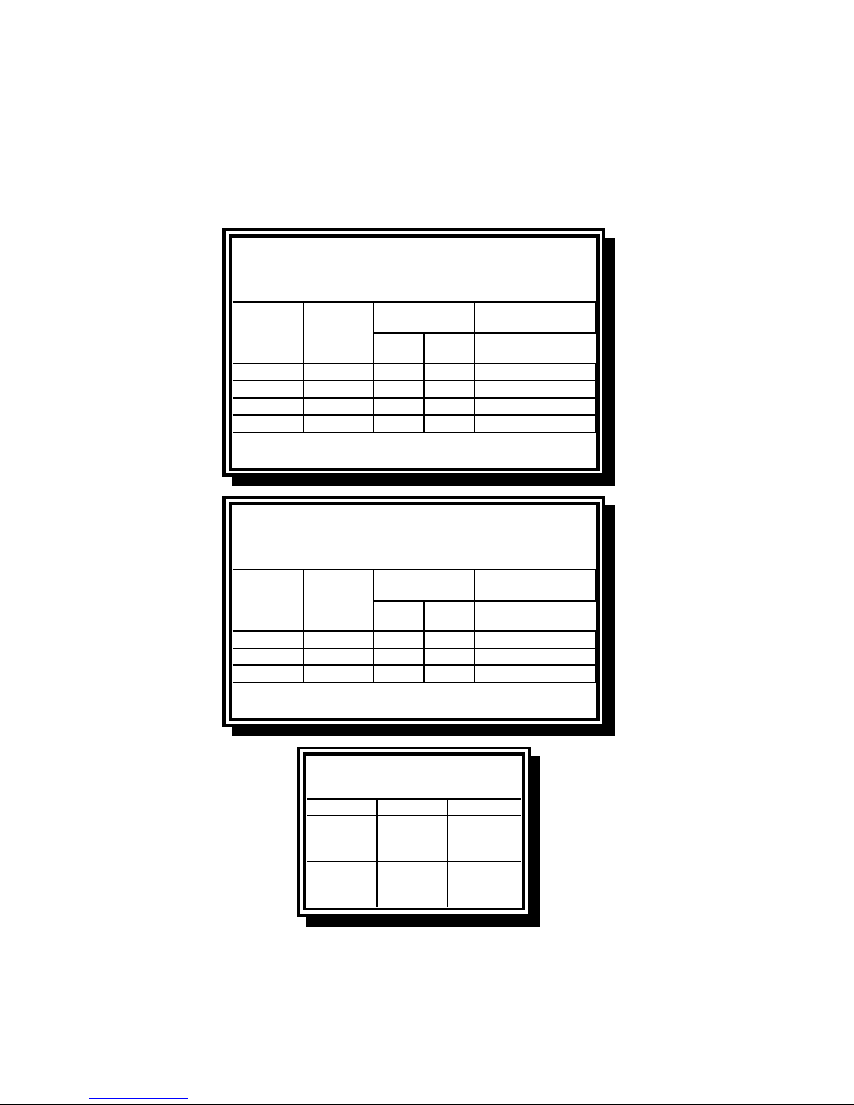
Gas Connection Pipe Sizes
(Minimum incoming pipe size should be 1 1/2" (38 mm))
4 or more
Gas Single Unit 2 - 3 Units
3/4
Natural
Propane 1/2" (13 mm) 3/4" (19 mm) 1" (25 mm)
Manufactured 1" (25 mm) 1 1/4" (33 mm) 1 1/2" (38 mm)
" (19 mm)
1" (25 mm) 1 1/4" (33 mm)
units*
* For distances of more than 20 feet (6 m) and/or
more than 4 fittings or elbows, increase the connection by one pipe size.
Before connecting new pipe to your unit, the pipe must be thoroughly blown out to remove any foreign particles. If these foreign particles get into the burner and controls, they will cause improper
and sometimes dangerous operation.
CE Standard
Required airflow for the combustion air supply is 2m3/h per kW.
1. Connect the quick-disconnect hose to the fryer quick-disconnect fitting under the front of the
fryer and to the building gas line.
NOTE: Some fryers are configured for a rigid connection to the gas supply line. These units are
connected to the gas supply line at the rear of the unit.
When using thread compound, use very small amounts on male threads only. Use a pipe thread
compound that is not affected by the chemical action of LP gases (Loctite™ PST56765 Sealant
is one such compound). DO NOT apply compound to the first two threads. This will ensure that
the burner orifices and control valve do not become clogged.
2. Open the gas supply to the fryer and check all piping, fittings, and gas connections for leaks. A
soap solution should be used for this purpose.
Never use matches, candles, or any other ignition source to check for leaks.
If gas odors are detected, shut off the gas supply to the fryer
at the main shut-off valve and contact the local gas company or an authorized
3. Close the fryer drain valve and fill the frypot with water and boil-out solution to the bottom OILLEVEL line at the rear of the frypot. Light the fryer and perform the boil-out procedures that are
described in the “Lighting Instructions” and “Boiling Out the Frypot” topics found in Chapter 3
of this manual.
DANGER
service agency for service.
2-6
Page 12
WARNING
“Dry-firing” your unit will cause damage to the frypot. Always ensure that melted
shortening, cooking oil, or water and boil-out solution is in the frypot before firing
your unit for any extended period.
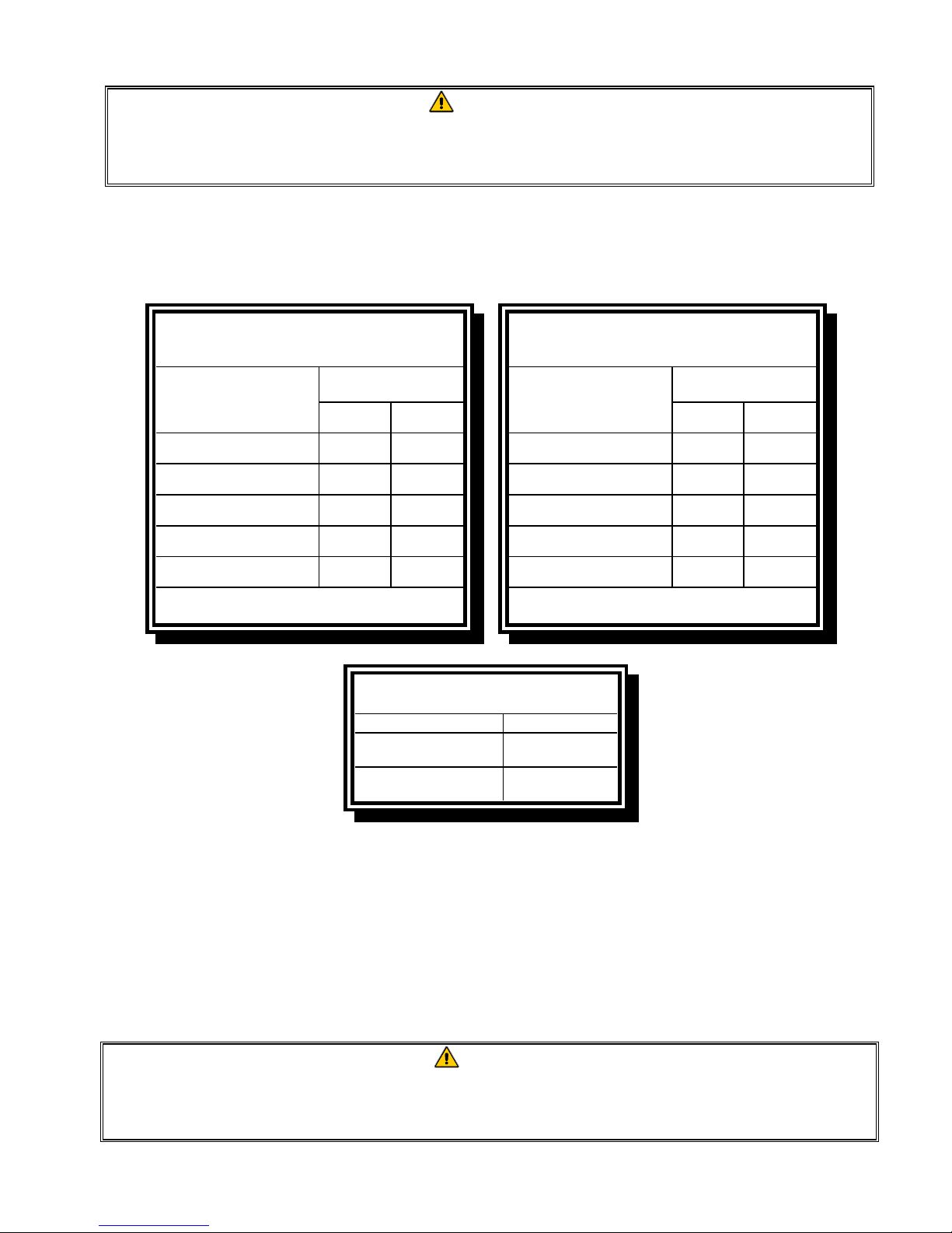
4. It is suggested that the burner manifold pressure be checked at this time by the local gas company or an authorized service agent. Refer to “Check Burner Manifold Pressure” in Chapter 5 of
this manual for the proper procedure. The accompanying tables list the burner manifold gas
pressures for the various gas types that can be used with this equipment.
CE Standard
Burner Manifold Gas Pressures
for Fryers Manufactured After April 1999
Pressure (mbar)
Single
Gas
Natural Gas Lacq
(G20) under 20 mbar
Natural Gas Groningue *
(G25) under 25 mbar
Natural Gas Groningue
(G25) under 20 mbar
Butane
(G30) at 28/30 or 50 mbar
Propane
(G31) under 37 or 50 mbar
* Belgian G25 = 7,0 mbar (single or dual)
Vat
77
10 10
10 10
17 17
20 20
Burner Manifold Gas Pressures
for Fryers Manufactured Through April 1999
Dual
Vat
Natural Gas Lacq
(G20) under 20 mbar
Natural Gas Gronigue *
(G25) under 25 mbar
Natural Gas Gronigue
(G25) under 20 mbar
Butane
(G30) at 28/30 or 50 mbar
Propane
(G31) under 37 or 50 mbar
* Belgian G25 = 7,0 mbar (single) or 6,5 (dual)
Gas
Non-CE Standard
Burner Manifold Gas Pressures
Gas Pressure
Natural
Propane
3" W.C.
0.73 kPa
8.25" W.C.
2.5 kPa
CE Standard
Pressure (mbar)
Single
Vat
76,5
10 9
10 9
17 16,5
20,2 18,5
Dual
Vat
5. Check the programmed temperature or analog controller thermostat setting. (Refer to Chapter 3,
Operating Instructions, for the setpoint programming instructions for your particular controller.)
2.5 Converting to Another Gas Type
Your fryer is configured at the factory for either natural gas or propane (LP) gas. If you desire to
switch from one type of gas to another, a gas conversion kit must be installed by a Factory
Authorized Service Center technician.
Switching to a different type of gas without installing the proper conversion kit may
result in fire or explosion! NEVER attach your fryer to a gas supply for which it is
DANGER
not configured.
2-7
Page 13
H52 Series Fryers manufactured for Non-CE countries use different burners for each type gas. The
burners in fryers built for Propane gas have a special gray-colored coating on the burner tiles to enable them to withstand the higher caloric value of the Propane gas. Burners designed for use in Propane units may be used in natural gas applications, but not vice versa.
Non-CE Gas Conversion Kits
Natural Gas to Propane (LP) Gas Propane (LP) Gas to Natural Gas
Full Vat: Part Number 826-1145 Full Vat: Part Number 826-1146
Dual Vat: Part Number 826-1147 Dual Vat: Part Number 826-1148
Units manufactured for export to CE countries are equipped with “universal” burners that may be
used with either natural (G20, G25) gas or Butane (G30) and Propane (G31) gasses.
CE Gas Conversion Kits for Units with Gas Valve 810-1011
G20 or G25 (Natural) to G30 or G31 Gas: G30 or G31 to G20 or G25 (Natural) Gas:
Part Number 826-1196 Part Number 826-1197
CE GAS CONVERSION INSTRUCTIONS
1. Between G20- and G25-type Natural Gas, adjust the gas pressure at the regulator. (Refer to the
CE Standard Burner Manifold Gas Pressure Chart.) Do not change the orifice.
2. Between a 2nd family (G20 or G25) and a 3rd family gas (G30 Butane or G31 Propane):
a. Change the orifices.
b. Change the gas valve spring (units with valve part number 810-1011only)
c. Adjust the manifold pressure.
3. Affix the new label included with the conversion kit next to the existing rating plate stating that
the gas type has been converted. Remove any references to the previously used gas from the existing rating plate. Conversion rating label PN 802-2144.
4. If the destination language changes, replace the labels. Call your local service agency or KES
for a label kit. The language of reference will be on the corner of the label.
2.6 Frypot Boil-Out
Before the fryer is first used for cooking product, it should be boiled out to ensure that any residue
from the manufacturing process has been eliminated.
In addition, after the fryer has been in use for a period of time, a hard film of caramelized vegetable
oil will form on the inside of the frypot. This film should be periodically removed by following the
boil-out procedure.
Refer to Fryers Maintenance Requirement Card (MRC) 14A for the boil-out procedure.
2-8
Page 14
g
CHAPTER 3: OPERATING FRYERS
WITH M100B™ COOKING COMPUTERS
3.1 Equipment Setup and Shutdown Procedures
Setup
WARNING
Fill the frypot to the bottom oil level line with vegetable oil before pressing the
ON/OFF switch to the ON position. Failure to do so could damage the frypot.
1. Fill the frypot with vegetable oil to the bottom OIL LEVEL line located on the rear of the frypot.
This will allow for oil expansion as heat is applied. Do not fill cold oil any higher than the bottom
line; overflow may occur as heat expands the oil.
2. Ensure that the power cord(s) is/are plugged into the appropriate receptacle(s). Verify that the
face of the plug is flush with the outlet plate, with no portion of the prongs visible.
3. Ensure that the vegetable oil level is at the top OIL LEVEL line when the vegetable oil is at its
programmed cooking temperature. It may be necessary to add vegetable oil to bring the level up
to the proper mark, after the oil has reached the programmed cooking temperature.
CAUTION
Do not add vegetable oil to the fryer between the time the computer is turned on and
the time it reaches programmed cooking temperature. Doing so is likely to cause
RECOVERY LOCKOUT (REC LOCK). See Section 3.4.
Shutdown
1. Press the ON/OFF switch to the OFF position (the display will show OFF).
2. Filter vegetable oil and clean fryers.
3. Place the frypot covers on frypots.
3.2 Finding Information
How do I… Pa
Activate/deactivate the BOIL-OUT mode? 3-10 Display “use time” information? 3-14
Change computer product/temp displays? 3-9 Enter a product number in a test menu? 3-12
Change cooking temperature setpoint? 3-11 Enter the program mode? 3-8
Calibrate computer to frypot temperature? 3-9 Enter the setup mode? 3-8
Change shake, pull, or quality times? 3-10 Program test item parameters? 3-12
Change the display language? 3-8 Reset the computer to factory defaults? 3-10
Configure the computer for a gas fryer? 3-8 Suppress a shake, QA, or duty function? 3-13
Configure the computer for full- or split-vat? 3-9 Turn factory-programmed menu item on/off? 3-14
Display Product Cycle Accumulator info? 3-14 Use the filter countdown time? 3-15
e How do I… Page
3–1
Page 15
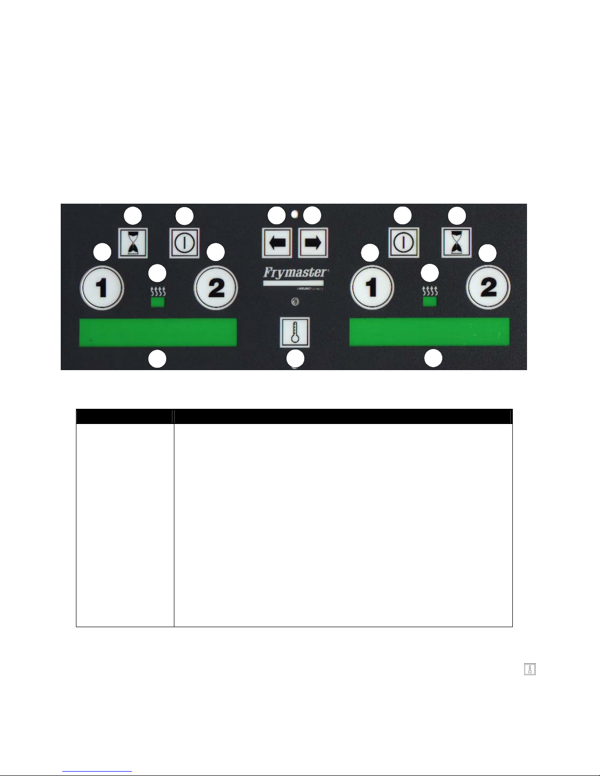
3.3 Introduction To The M-100B™ Cooking Computer
The M-100B cooking computer, illustrated below, automatically maintains fryer temperature to cook
products according to preprogrammed cooking specifications. The computer also acts as a cooking
process timer, displaying the remaining cooking time for each product and alerting the operator by
sound and display message to shake or pull the product at the correct time. It also signals quality
control (hold-time) limits. The computer automatically adjusts cooking times to compensate for
variances in product temperature and basket load so that, for example, a full basket of cold fries will
be cooked to the same quality as half a basket of fries at room temperature.
H
D
L
E
J
B
N
O
F
A
M
I
G
K
C
ITEM DESCRIPTION
A Temperature Display Switch
B Left LED Display
C Right LED Display
D Cook Switch #1, Left
E Cook Switch #2, Left
F Cook Switch #1, Right
G Cook Switch #2, Right
H Recovery/Use Time Recall Switch, Left
I Recovery/Use Time Recall Switch, Right
J Light - Left Heating Mode Indicator
K Light - Right Heating Mode Indicator
L Switch - Left ON/OFF
M Switch - Right ON/OFF
N Switch - Left Product Selection
O Switch - Right Product Selection
To quickly determine the software version number and the current configuration of an M-100B
computer, with the computer turned OFF (OFF in both displays) press the temperature check
switch. The displays will automatically cycle through the version number, power configuration (gas
or electric), EPRA configuration (On or Off), and frypot configuration (full or split).
3–2
Page 16

The M-100B is factory-programmed with McDonalds’s cooking specifications for a group of seven
standard products. The cooking times and temperature settings for these factory-programmed products
can be changed by store personnel if required. Additionally, two test menus are available for store
personnel to program product names, cooking times, temperature settings, and shake or duty times for
products not included on the factory-programmed menu. The test menus can also be set to
automatically adjust the cooking rate to compensate for product variances.
For units equipped with built-in filtration, the computer times the polishing process and alerts the
operator when the polishing time has elapsed. (Polishing refers to circulating the vegetable oil
through the filtration system for a specified time.)
The fryer has two built-in high-limit protection features. If the temperature in the frypot reaches
approximately 410°F (210°C), the computer opens the heat relay circuit, turning the burners off. If
the temperature in the frypot reaches 450°F (232°C), a mechanical high-limit shuts off electrical
power to the coil of the gas valve(s). The operator should periodically test each of the high-limit
protection features to verify that they are operating correctly. Refer to Grills/Fryers Maintenance
Requirement Card (MRC) 15 for the procedure.
3.4 M-100B™ Computer Operating Instructions
WARNING
Before pressing the on/off switch to the ON position, ensure that the frypot is
properly filled with vegetable oil. See Section 3.1.
Operating the Computer on Full-Vat Fryers
1. Turn ON the cooking computer by pressing the right ON/OFF switch . A product name (for
example, FR FRIES) will appear in the right LED display.
2. If the frypot temperature is below 180°F (82°C), the computer will automatically enter a warm-up
cycle (often called a melt cycle). The burners will cycle on and off repeatedly, allowing the
vegetable oil to heat gradually, without scorching. During the warm-up cycle, the right heating
mode indicator
will alternately illuminate and go out as the burners cycle on and off. Within
about 45 minutes, the computer will exit the warm-up cycle and the heat mode indicator will
remain continuously illuminated.
3. The M-100B computer allows the operator to use both sides of the computer if desired. By having
both sides of the computer on, the operator can select two products that have the same cooking
temperature, but different cooking times. Using a pair of twin baskets, both products can be
cooked at the same time.
4. To activate the left side of the computer, press the left ON/OFF switch . A product name will
be displayed in the left LED display.
5. Select the product to be cooked by pressing the right product selection switch
(or, if both sides
of the computer are ON, the left product selection switch ) until the desired product is
displayed.
3–3
Page 17

Once the frypot temperature is above 180°F (82°C), but still 15°F (8°C) or more below the setpoint
temperature for the product displayed (for example, french fries), the computer will alternately display
LOW TEMP and FR FRIES, and the right heating mode indicator will remain continuously
illuminated.
The cooking cycle cannot be started until the cooking oil is within ±15°F (8°C) of the programmed
setpoint. When the frypot temperature is within ±15°F (8°C) of the programmed setpoint, the product
name will be displayed continuously, indicating that the fryer is ready to cook the displayed product.
Operating the Computer on Split-Vat Fryers
1. Turn ON the cooking computer by pressing the ON/OFF switches . Pressing the left switch
turns on the left side of the computer; pressing the right switch turns on the right side. A product
name (for example, FR FRIES) will appear in the LED display corresponding to the switch
pressed.
2. If the frypot temperature is below 180°F (82°C), the computer will automatically enter a warm-up
cycle (often called a melt cycle). The burners will cycle on and off repeatedly, allowing the
vegetable oil to heat gradually, without scorching. During the warm-up cycle, the heating mode
indicator will alternately illuminate and go out as the burners cycle on and off. Within 45
minutes, the computer will exit the warm-up cycle and the heat mode indicator will remain
continuously illuminated.
3. Select the product to be cooked by pressing the left or right product selection switches ,
depending upon the vat in which you wish to cook.
4. Once the frypot temperature is above 180°F (82°C), but still 15°F (8°C) or more below the
setpoint temperature for the product displayed (for example, french fries), the computer will
alternately display LOW TEMP and FR FRIES, and the heating mode indicator will remain
continuously illuminated.
5. The cooking cycle cannot be started until the cooking oil is within ±15°F (8°C) of the
programmed setpoint. When the frypot temperature is within ±15°F (8°C) of the programmed
setpoint, the product name will be displayed continuously, indicating that the fryer is ready to
cook the displayed product.
Viewing the Frypot Temperature (Actual or Setpoint)
To display the actual frypot temperature, press the temperature check switch
once. To display the
setpoint temperature, press the switch twice.
Cooking Product (Full-Vat or Split-Vat)
1. Fill basket(s) with product, lower the basket into the vegetable oil, then press the cook switch (
2
) that corresponds to the full- or split-vat to be used. This will activate the cooking cycle of
or
1
the product.
3–4
Page 18

Example 1: In a full-vat fryer, press cook switch 1 when the first basket of twin baskets of fries
is dropped. Halfway through the first cooking cycle, drop the second basket and press cook
switch 2.
Example 2: The M-100B is programmed to cook Crispy Chicken (CSPY) and Chicken
McNuggets (NUG) in the same side of a split-vat arrangement. Cook switch
1
corresponds to
Crispy Chicken, and cook switch 2 corresponds to Chicken McNuggets.
2. The display will show the number of minutes and seconds of cooking time remaining.
3. At the programmed shake time, an audible alarm will sound and the display will flash SHAKE.
After shaking the basket, press the corresponding cook switch, 1 or 2, to cancel the alarm.
4. After the completing the cooking time, an audible alarm will sound and the display will flash
1
pull. Remove the indicated basket and press the corresponding cook switch,
the alarm. If no other products are being cooked in the frypot, the display shows
or 2, to cancel
7:00 QA
indicating that the quality timer is counting down. If the quality time is set for some time other
than 7:00 minutes, the display starts counting down from that time. (QA is not available for
McChicken, Crispy Chicken or Filet-o-Fish).
5. When the quality time expires, an audible alarm will sound, and the display will flash QA. Cancel
the alarm by pressing the corresponding cook switch, 1 or 2.
NOTE: When you initiate a new cook cycle, the quality time will automatically reset.
3.5 M-100B™ Computer Problem Condition Indicators
Recovery Out of Range (REC LOCK)
Recovery time is an indication of the condition of the fryer. When the fryer is first turned on, the
computer records the amount of time it takes to heat the cooking oil from 270°F (132°C) to 320°F
(160°C). Also, anytime the temperature of the oil drops below 250°F (121°C), such as when cold oil
is added, the computer will check the recovery time. If the fryer takes longer than 2 minutes and 35
seconds to recover, the display will show REC LOCK and the computer will lock out.
To clear the REC LOCK condition, enter the program mode (see How to Enter the Program Mode on
Page 3-10) and push the temperature check switch
(see diagram on following page).
It is easy to view the currently recorded recovery time with the computer ON. Press the recovery
recall switch
for the frypot you wish to check. On full-vat units, press the right switch.
If REC LOCK occurs three or more times within a week, verify that oil is not being added while the
fryer is heating (that is, while a heat mode indicator is illuminated) and that the fryer’s power cord
is fully plugged in. If oil is not being added while the fryer is heating, and the power cord is fully
plugged in, have the fryer checked by a qualified service agent.
3–5
Page 19

Open Drain Valve Indication
If, when the ON/OFF switch is pressed to the ON position, the display reads IGNITION
FAILURE, verify that the drain valve is fully closed. A drain safety switch built into the drain valve
assembly prevents the coil of the gas valve(s) from being energized if the drain valve is not
completely closed. After verifying that the valve is fully closed, turn the computer OFF* for at least 5
seconds, then turn it back on. If the message reappears, there is a problem in the electrical circuitry of
the fryer or the computer. Contact your Frymaster Factory Authorized Service Center (FASC).
* On early-version M-100B split-vat units, BOTH computers must be turned off, even though the
problem condition may be associated with only one vat.
Low Temperature Indication
If the frypot temperature drops to more than 45°F (25°C) below the programmed setpoint temperature
during the cooking cycle, the cook switches will lock, the display will flash
lOW TEMP and an
audible alarm will sound. If the frypot temperature returns to a range between 45°F (25°C) to 15°F
(8°C) of setpoint, the audible alarm will stop, but the cook switches remain locked and the display
3–6
Page 20

alarm continues flashing. All functions return when the frypot temperature is within 15°F (8°C) of
the programmed setpoint.
Probe Failure Indication
If the temperature probe fails, the display will flash PROBE FAILURE and an audible alarm will
sound. To cancel the alarm, turn the computer OFF. In split-vat fryers, turn off the side in which the
failure occurred. If a probe fails during the high-limit test, PROBE FAILURE is displayed.
NOTE: If the temperature probe fails in the left side of a split-vat, that side cannot be turned back
ON once it has been turned OFF.
3.6 M-100B™ Computer Set-Up and Programming Instructions
The M-100B computer has three modes of operation. In addition to the Cooking Mode, which was
discussed in Sections 3.3 and 3.4, there is a Setup Mode and a Programming Mode. (The cooking
mode is the computer’s default mode – when the computer is turned on, it comes up in the cooking
mode.)
In the Setup Mode, the operator can:
• change the computer’s display language
• configure the computer for use on gas fryers
• configure the computer for use on either a full-vat or a split-vat fryer
• specify how the computer displays product names and temperatures
• calibrate computer temperature to actual frypot temperature
• activate or deactivate the frypot BOIL OUT feature
In the Program Mode, the operator can:
• reset the computer to the factory default settings
• change the shake, pull, and QA (hold) times for menu items
• change the cooking temperature setpoints for menu items
• add products and cooking parameters to the two test menus
• suppress a duty function in a menu item
• turn the display of a menu item in the factory-programmed menu on or off
• display usage information that is automatically recorded by the computer
3–7
Page 21

3.6.1 M-100B™ Computer Setup Mode
How to Enter the Setup Mode
1. Turn both sides of the computer OFF by pressing the switches. OFF will appear in both LED
displays.
2. Press the right 1, 2 and switches simultaneously.
3. Release all 3 switches at the same time. M100B, then SETUP will appear briefly in the left
display, then BOIL-OUT will appear in the left display and YES or NO will appear in the right
display.
How to Change the Computer’s Display Language
1. Enter the setup mode. See How to Enter the Setup Mode above.
2. Press and release the switch until the word language appears in the left LED display.
3. Press the right 1 or 2 switch until the desired language (English, French, French-Canadian,
Spanish, or Portuguese) is displayed in the right LED display.
4. When the desired language is displayed, press either ON/OFF switch
to lock in the selection.
The right display will show loading for about 5 seconds, indicating that the computer’s
display language is being changed, then both displays will change to OFF.
How to Configure the Computer for Use on a Gas Fryer
1. Enter the setup mode. See How to Enter the Setup Mode above.
2. Press and release the switch until GAS Yes or GAS no appears in the LED displays.
3. Gas nO indicates the computer is configured for use on an electric fryer; Gas YES indicates
1
the computer is configured for use on a gas fryer. Press the right
or 2 switch to change the
configuration.
3–8
Page 22

4. Press the switch to save the settings.
5. Press either ON/OFF switch to save the setting and exit the setup mode. Both displays will
change to OFF.
How to Configure the Computer for Use on Either a Full-Vat or a Split-Vat Fryer
1. Enter the setup mode. See How to Enter the Setup Mode on Page 3-8.
2. Press and release the switch until 1 vat appears in the left display.
3. Press the right 1 or
2
switch to toggle back and forth between full-vat (yes) or split-vat (NO).
4. Press the switch to save the settings.
5. Press either ON/OFF switch
to exit the setup mode. Both displays will change to OFF.
How to Change Computer Product/Temperature Displays
1. Enter the setup mode. See How to Enter the Setup Mode on Page 3-8.
2. Press and release the switch until the word DISPLAY appears in the left display.
3. Press the right 1 or 2 switch to toggle back and forth between constant product display
(CONSTANT) or alternating temperature and product display (ALT).
4. Press the switch to save the settings.
5. Press either ON/OFF switch to exit the setup mode. Both displays will change to OFF.
How to Calibrate Computer Temperature to Actual Frypot Temperature
NOTE: For this procedure, actual frypot temperature refers to the temperature of the oil in the frypot
as measured with a good-grade thermometer or pyrometer. The computer’s temperature can only be
adjusted ±5°F (±3°C). The computer cannot be adjusted to a temperature greater than 375°F (191°C).
1. Enter the setup mode. See How to Enter the Setup Mode on Page 3-8.
2. Press and release the
switch until CALIB appears in the display.
3. Press the temperature check switch . The frypot temperature sensed by the computer will be
displayed. In split-vat units, the temperatures for each side will be displayed.
4. For the left side of a split-vat: Press the left 1 switch to go UP a degree (maximum of 5 for
Fahrenheit or 3 for Celsius). Press the left 2 switch to go DOWN a degree (maximum of 5 for
Fahrenheit or 3 for Celsius).
3–9
Page 23

For the right side of a split-vat or for a full-vat: Press the right 1 switch to go UP a degree
(maximum of 5 for Fahrenheit or 3 for Celsius). Press the right 2 switch to go DOWN a degree
(maximum of 5 for Fahrenheit or 3 for Celsius).
5. Press the switch to save the settings.
6. Press either ON/OFF switch to exit the setup mode. Both displays will change to OFF.
How to Activate or Deactivate the Frypot BOIL-OUT Feature
1. Enter the setup mode. See How to Enter the Setup Mode on Page 3-8.
2. Press and release the switch until BOIL-OUT appears in the display.
3. Press the right 1 or 2 switch to toggle the boil-out mode ON or OFF.
4. Press the switch to save the settings.
5. Press either ON/OFF switch to exit the setup mode. Both displays will change to OFF.
3.6.2 M-100B™ Computer Programming Mode
How to Enter the Program Mode
1. Press the ON/OFF switches until both displays of cooking computer indicate OFF. Press the
left product selection switch and the left 1 and 2 cook switches simultaneously. Release all
three switches at the same time.
2. When the program mode has been entered, the display will flash M-100B computer
briefly, followed by the software version number. After a few seconds, Fr fries yes or
Fr fries no will be displayed, depending upon previous program settings.
How to Reset the Computer to the Factory Defaults
While in the program mode, press all 4 cook switches (left and right 1 and 2) simultaneously to reset
the computer to the factory defaults. See How to Enter the Program Mode above. Updating
menu
will flash in the display, followed by epra cleared and cooks cleared.
After a few seconds, Fr fries yes will be displayed, indicating that the computer has been
reset to the factory defaults.
How to Change the Shake, Pull, Or Quality Times for Menu Items
1. Enter the program mode. (See How to Enter the Program Mode above.)
2. Press and release the switch until the product to be changed appears in the left display.
3–10
Page 24

3. Press and release the switch until the function to be changed (SHAKE, PULL, or QA)
appears in the left display. The current time setting and automatic (AUTO) or manual (MAN)
alarm cancel mode options appear in the right display.
NOTE: Shake Time refers to the programmed time at which the operator will be prompted by an
audible alarm to shake the basket, but not stop the cooking process. Pull Time refers to the
programmed time at which the product is fully cooked and at which the operator will be prompted
by an audible alarm to remove the basket from the cooking oil. QA Time refers to the maximum
time that a product may be held after the cooking cycle has completed.
NOTE: When the programmed time has elapsed, the automatic alarm-cancel mode (AUTO)
audible alarm will sound three times and then stop. When the programmed time has elapsed, the
manual alarm cancel mode (MAN) audible alarm will sound until the operator presses the cook
switch (1 or 2) that was pressed to start the cooking cycle.
4. Press the right
2
switch to toggle between automatic alarm cancel mode (AUTO) and manual
alarm cancel mode (MAN).
5. To change the times, use the following switches:
Left
Left
Left
Right
Minutes (in increments of ten)
1
Minutes (in increments of one)
2
Seconds (in increments of ten)
1
Seconds (in increments of one)
6. Press the switch to lock in the new settings, and either ON/OFF switch to exit the
programming mode. Both displays will show OFF.
How to Change the Cooking Temperature Setpoint
1. Enter the program mode. See How to Enter the Program Mode on Page 3-10.
2. Press and release the switch until the menu item to be changed is displayed.
3. Press the switch to show the cooking temperature setpoint, displayed as SET-TEMP in the
left display. The current setpoint temperature is in the right display (for example-350F). The
temperature will be in Fahrenheit (F) or Celsius (C). Pressing the right
2
switch toggles the
computer between Fahrenheit (F) and Celsius (C).
4. To change the temperature, use the following switches:
Left
Left
Right
1
2
1
Hundreds
Tens
Ones
NOTE: The computer cannot be programmed for a temperature greater than 375°F (191°C).
5. Exit the program mode by pressing either ON/OFF switch .
3–11
Page 25

How to Enter a Product Name in a Test Menu
1. Enter the program mode. See How to Enter the Program Mode on Page 3-10.
2. Press the switch to select Test Menu 1 or 2.
3. Press the switch to enter the edit mode. The right display will show EDIT and a blinking
cursor will appear in the left display.
4. To enter a letter, use the left 1 switch to go UP in the alphabet. Use the left 2 switch to go
DOWN in the alphabet.
NOTE: Characters available are the letters A-Z and the numbers 0-9. Special characters *, *, -,
?, and / are also available, as is a blank space.
NOTE: Pressing the left switch will reset the product name to the factory defaults.
5. To move to a different character position, use the or switches.
6. To EXIT and SAVE the product name entry, press the switch. SAVE will flash in the right
display, followed by YES or NO, indicating whether the menu item is active or not. Press the
right 1 or 2 switch to toggle between yes and no.
7. Press the switch to cycle through the Duty Times, Pull Time, QA (hold) Time, and Cooking
Temperature Setpoint settings. Program the times and the set point in accordance with the section
that follows.
How to Program Duty Times, Pull Time, QA Time, and Setpoint for a Test Menu Item
NOTE: Duty Time refers to an operator-specified time within a cooking cycle when the computer
will sound an alarm to prompt a particular duty such as shaking the basket.
1. Enter the program mode. See How to Enter the Program Mode on Page 3-10.
2. Press the switch to select the desired test menu.
3. Press the switch. DUTY1 will appear in the left display. The currently programmed time
appears in the right display. To program the time, use the following switches:
Left
Left
Left
Right
Minutes (in increments of ten)
1
Minutes (in increments of one)
2
Seconds (in increments of ten)
1
Seconds (in increments of one)
Press the right
2
switch to toggle between the manual alarm cancel mode (MAN) and the
automatic alarm cancel mode (AUTO).
NOTE: In the automatic alarm cancel mode (AUTO), when the programmed time has elapsed,
an audible alarm will sound three times and then stop. In the manual alarm cancel mode (MAN),
3–12
Page 26

an audible alarm will sound when the programmed time has elapsed until the operator presses the
cook switch (1 or 2) that was pressed to start the cooking cycle.
4. Press the switch, DUTY2 appears in the left display. The currently programmed time appears
in the right display. Program the time in the same manner as Duty1 time.
NOTE: Enter a time of 00:00 to bypass this option.
NOTE: In the steps that follow, Pull Time refers to the programmed time at which the product is
fully cooked and an audible alarm will prompt removal of the basket from the cooking oil. QA
Time refers to the maximum time that a product may be held after the cooking cycle has
completed.
5. Press the switch to display PULL in the left window. Program the pull time in the same
manner as the duty times.
6. Press the switch to display QA in the left window. Program the QA time in the same manner
as the duty times.
7. Press the switch to show the cooking temperature setpoint, displayed as SET-TEMP in the
left display. The current setpoint temperature is in the right display (for example-350F). The
temperature will be in Fahrenheit (F) or Celsius (C). Pressing the right
2
switch toggles the
computer between Fahrenheit (F) and Celsius (C). To change the temperature, use the following
switches:
Left
Left
Right
1
2
1
Hundreds
Tens
Ones
NOTE: The computer cannot be programmed for a temperature greater than 375°F (191°C).
8. Press the switch to show the status of the Test Menu Cook Time Compensation feature. The
display will show PROBE in the left window and YES or NO in the right window. With the
feature set to YES, the cooking time of the product will be temperature-compensated; with the
1
feature set to N0, the product cooking time will not be compensated. Press the right
or 2
switch to toggle between YES or NO.
9. Exit the program mode by pressing the right switch. Both displays will show off.
How to Suppress a Shake, QA, or Duty Function
1. Enter the program mode. See How to Enter the Program Mode on Page 3-10.
2. Press and release the switch until menu item to be modified is displayed in the left window.
3. Press and release the
switch until the function to be suppressed is displayed in the left window.
3–13
Page 27

4. Use the cook switches 1, 2,
1
from left to right to set the time display to read 000. This will
suppress the function during the cooking cycle. To reactivate the function, follow steps 1 through
3 to enter a time for the function.
5. Exit the program mode by pressing the right
switch.
How to Turn the Display of a Factory-Programmed Menu Item On and Off
1. Enter the program mode. See How to Enter the Program Mode on Page 3-10.
2. Press and release the switch until the menu item to be turned on or off is displayed in the left
window.
3. The right display will show YES or NO. To turn the menu item OFF, press either of the right
1
2
or
switches to set the option to NO. To turn the menu item ON, change the option to YES.
4. Exit the Program Mode by pressing the right switch. Both displays will read OFF.
How to Display “Use Time” Information
NOTE: This feature is used to determine the total amount of time that a fryer has been cooking.
1. Enter the program mode. See How to Enter the Program Mode on Page 3-10.
2. Press the left switch to display use time for the left side of a dual-vat unit. Press the right
switch to display use time for a full-vat unit or the right side of a dual-vat unit.
3. To reset use time data to zero, while pressing one of the switches, press the same side's 1 and
2
switches, then release them simultaneously.
NOTE: The simultaneous release of these three switches is critical. If not done correctly, data
will not reset.
How to Display the Product Cycle Accumulator Information
NOTE: This feature keeps a running total of cooking cycles per product.
1. Enter the program mode. See How to Enter the Program Mode on Page 3-10.
2. Press the left or right switch.
3. For the left vat, press the switch. For the right or for a full-vat, press the switch. A running
total of cooking cycles per product will be displayed.
4. To clear the accumulated times from computer memory, press either switch, then the
switch.
3–14
Page 28

How to Use the Filter Countdown Timer
NOTE: This feature starts a five-minute countdown timer to time the polishing of vegetable oil
during the filtering process. Polishing refers to circulating the vegetable oil through the filtration
system for a specified time. This feature does not have any direct control over the filtration process; it
is only a timer.
1. With the computer ON, press and release the switch until FILTER appears in the display.
(For split-vat units, press and release the switch for the left vat.)
2. Press either of the right 1 or 2 switches. The computer will begin to countdown from five
minutes to zero. (For split-vat units, press either of the left 1 or 2 switches for the left vat.)
3–15
Page 29

CHAPTER 4: OPERATING FRYERS
WITH ANALOG CONTROLLERS
4.1 Equipment Setup and Shutdown Procedures
Setup
WARNING
Fill the frypot to the bottom oil level line with vegetable oil before pressing the power
switch to the ON position. Failure to do so could damage the frypot.
Fill the frypot with vegetable oil to the bottom OIL LEVEL line located on the rear of the frypot. This
will allow for oil expansion as heat is applied. Do not fill cold oil any higher than the bottom line;
overflow may occur as heat expands the oil.
Ensure that the power cord(s) is/are plugged into the appropriate receptacle(s). Verify that the face of
the plug is flush with the outlet plate, with no portion of the prongs visible.
Set the thermostat knob to the desired frying temperature.
Ensure that the vegetable oil level is at the top OIL LEVEL line when it is at its intended cooking
temperature. It may be necessary to add vegetable oil to bring it up to the proper level.
Shutdown
1. Press the POWER switch to the OFF position (the POWER light will go out).
2. Filter vegetable oil and clean fryers.
3. Place the frypot covers on the frypots.
4.2 Introduction to the Analog Controller
The analog controller, illustrated on the following page, is used to adjust and maintain vegetable oil at
the temperature indicated by the thermostat knob. The fryer has two built-in high-limit protection
features. If the temperature in the frypot reaches approximately 410°F (210°C), the computer opens
the heat relay circuit, turning the elements off. If the temperature in the frypot reaches 450°F (232°C),
a mechanical high-limit shuts off electrical power to the elements. The operator should periodically
test each of the high-limit protection features to verify that they are operating correctly. Refer to page
4-3, Analog Controller High-Limit Check, or the Grills/Fryers Maintenance Requirement Card (MRC)
15 for the procedure.
The analog controller has no timing features. Shake, pull, and QA (hold) times must be monitored by
the operator.
4-1
Page 30

C
E G
M
N
H F
D
POWER
OFF
HEAT TROUBLE
POWER
ON
2
0
4
2
0
2
2
A K L
3
80
2
0
0
6
2
1
0
1
1
0
0
0
3
4
1
1
5
2
0
0
3
1
1
6
0
0
0
1
0
2
0
1
7
0
1
8
0
1
9
0
o
C
o
F
I
SECOND SECOND
0
3
4
0
3
6
0
2ND
1ST
HI-LIMIT
TEST
2ND
1ST
TROUBLE HEAT
SPLIT VAT CONTROLLER ILLUSTRATED
FULL VAT CONTROLLER HAS ONLY LEFT SET OF CONTROLS
ITEM DESCRIPTION
A Power Switch, Left or Full-Vat - Controls electrical power to fryer.
0
3
8
2
0
0
6
2
0
1
4
2
0
1
1
0
2
2
0
0
0
3
4
1
1
5
2
0
0
3
1
0
2
0
0
1
0
2
0
1
6
0
1
7
0
1
8
0
1
9
0
o
C
o
F
J
POWER
3
4
0
3
6
0
ON
POWER
OFF
B
B Power Switch, Right Vat - Controls electrical power to fryer.
C Power-On Light, Left or Full-Vat - Indicates when electrical power to fryer is ON.
D Power-On Light, Right Vat - Indicates when electrical power to fryer is ON.
E Heating Mode Light, Left or Full-Vat - Indicates when burner is firing.
F Heating Mode Light, Right Vat - Indicates when burner is firing.
G Trouble Light, Left or Full-Vat - Indicates over high-limit or problem in heat control circuitry.
H Trouble Light, Right Vat - Indicates over high-limit or problem in heat control circuitry.
I Thermostat Control Knob, Left or Full-Vat - Sets desired frying temperature.
J Thermostat Control Knob, Right Vat - Sets desired frying temperature.
K Hi-Limit Test Switch, Left or Full-Vat - Tests high-limit thermostat for left vat (or full-vat).
L Hi-Limit Test Switch, Right Vat - Tests high-limit thermostat for right vat.
M Second Hi-Limit Test Light, Left or Full-Vat - Indicates fryer is in second high-limit test mode.
N Second Hi-Limit Test Light, Right Vat - Indicates fryer is in second high-limit test mode.
4-2
Page 31

4.3 Analog Controller Operating Instructions
WARNING
Before pressing the power switch to the ON position, ensure that the frypot is
properly filled with vegetable oil. See Section 4.1.
1. Verify that the thermostat knob is set to the desired cooking temperature. For split-vat units, set
both knobs.
2. Press the power switch to the ON position. The POWER light will illuminate. For split-vat units,
both power switches must be placed in the ON position if both vats are to be used.
3. If the frypot temperature is below 180°F (82°C), the controller will automatically enter a warm-up
cycle (often called a melt cycle). The heating elements will cycle on and off repeatedly, allowing
the vegetable oil to heat gradually, without scorching. During the warm-up cycle, the heating
mode light will alternately illuminate and go off as the elements cycle on and off. Within about 45
minutes, the controller will exit the warm-up cycle and the heating mode light will remain
continuously illuminated.
4. When the vegetable oil temperature reaches the thermostat knob setpoint, the elements will cycle
OFF and the heating mode light will go off, indicating that the fryer is ready for the cooking
process to begin.
4.4 Analog Controller High-Limit Check
Tools needed: Maple Paddle, Fry Vat Probe.
NOTE: Conduct this test when fryer will not be needed for about one hour, and when the vegetable
oil is due to be changed. Discard the vegetable oil after completing this check
NOTE:
Check high-limit on only one vat at a time.
Grease filters must be in place and exhaust fans MUST be ON during entire high-limit
1. The vegetable oil should be at the normal/shortening level line. Add vegetable oil if necessary.
2. Remove the computer probe from the probe holder and replace it with fry vat probe.
3. Turn the vat power switch to “ON” and set thermostat knob to its highest setting. Wait for heating
light to go OFF.
CAUTION
control-check procedure.
4-3
Page 32

NOTE: You must agitate the vegetable oil with a maple paddle during the entire high-limit control-
check procedure.
CAUTION
If after completing both high-limit tests you find only the second high-limit operates
properly, the vat can be used if it is absolutely necessary, but with extreme care. The
controller must be replaced immediately after this period of necessity. If the second
high-limit does not work the vat must not be used until the second high-limit has been
replaced. If the first high-limit feature activates at less than 400°F (204°C), do not
replace the controller unless it interferes with proper cooking. If the second high-limit
activates at less than 425°F (218°C), do not replace it unless it prevents you from
checking the first high-limit feature.
4. Press and hold the vat high-limit test switch in the "first high-limit" position.
Expected Result: Gas burner turns OFF and "TROUBLE" light comes ON. Vegetable oil
temperature should be between 400º and 425ºF (204º and 218ºC).
5. Press and hold the vat high-limit test switch in the "second high-limit" position.
NOTE: When the trouble light comes ON, or the temperature exceeds 425ºF (218ºC), release the
switch.
Expected Result: Gas burner turns OFF and the second high-limit comes ON. The vegetable oil
temperature should be between 425º and 450ºF (218º and 232ºC).
CAUTION
When the second high-limit light comes on, or the temperature exceeds 450°F (232°C),
release switch.
6. Turn the power switch to the “OFF” position. One vat must remain ON to ensure hood fan
remains ON.
7. Remove the fry vat probe and reinstall the computer probe into the vat.
8. Allow vegetable oil to cool for one hour before discarding. See statement on discarding oil
(Chapter 5).
NOTE: Hot oil must not be transported until it cools to 100°F (38°C) or less.
High-Limit check is complete. Repeat procedure for each remaining vat.
4-4
Page 33

CHAPTER 5: FILTERING
5.1 Draining and Manual Filtering
DANGER
Always wear appropriate protective gloves when draining or filtering.
Allow cooking oil to cool to 100ºF (38ºC) or lower before draining to an appropriate
container for disposal.
NOTE: If your fryer is not equipped with a built-in filtration
system, the cooking oil must be drained into another suitable
container. For safe, convenient draining and disposal of used
cooking oil, Frymaster recommends using the Vegetable Oil
Disposal Unit, illustrated at right.
1. Turn the fryer controller OFF. Screw the drainpipe
(provided with your fryer) into the drain valve. Make sure
the drainpipe is firmly screwed into the drain valve.
2. Position the Vegetable Oil Disposal Unit (or a metal
container with a sealable cover) under the drainpipe.
NOTE: The metal container must be able to withstand
the heat of the cooking oil and hold hot liquids. If you
intend to reuse the oil, Frymaster recommends that a
Frymaster filter cone holder and filter cone be used when
a filter machine is not available. If you are using a
Frymaster filter cone holder, be sure that the cone holder
rests securely on the metal container.
3. Open the drain valve slowly to avoid splattering. If the drain valve becomes clogged with food
particles, use the Fryer’s Friend (poker-like tool) to clear the blockage from the frypot side.
DO NOT insert anything into the drain from the front to unclog the valve. Hot oil will
DO NOT hammer on the drain valve with the Fryer’s Friend. This will damage the
drain valve ball and prevent the valve from sealing securely, resulting in a leaky
4. After draining the oil, clean all food particles and residual oil/shortening from the frypot. BE
CAREFUL, this material may still cause severe burns if it comes in contact with bare skin.
DANGER
rush out, creating an extreme hazard.
WARNING
valve.
5-1
Page 34

5. Close the drain valve securely and fill the frypot with clean cooking oil to the bottom OIL-
LEVEL line.
5.2 Operating the Built-In Filtration System
The FootPrint III (FP III) filtration system allows the cooking oil in one frypot to be safely and efficiently filtered while the other frypots in a battery remain in operation.
Most reported problems with these systems are caused by improper operation. Careful attention to
the step-by-step instructions that follow will ensure that your system operates as intended.
PREPARING THE FILTER UNIT FOR USE and CHANGING THE FILTER PAPER
1. Turn the controller OFF.
2. Pull the filter unit from the cabinet, open the cover, remove the crumb tray, and remove the
paper hold-down ring.
3. If changing the filter paper after filtering,
remove and discard the used paper (or optional filter pad). Be careful, the oil-soaked
paper or pad may be very hot and can
cause severe burns.
After removing the filter paper (or pad),
remove the metal filter screen and pan, and
clean them thoroughly with a solution of hot
water and detergent. Ensure that all breading
and food particles are removed from the pan.
Dry the pan thoroughly with a soft cloth or
paper towels.
Allow the filter screen to dry completely,
then reinstall it in the filter pan.
DANGER
Always wear appropriate protective gloves when changing the filter paper.
5-2
Page 35

4. Verify that the filter screen is flat in the bottom of the pan. Lay a sheet of filter paper over the
top of the pan, overlapping on all sides (or place an optional filter pad in the bottom of the pan.)
NOTE: If using the optional filter pad, ensure that the rough-textured side of the pad is up.
5. Position the hold-down ring over the filter paper
and lower the ring into the pan, allowing the paper
to fold up around the ring as it is pushed to the bottom of the pan.
If using the optional filter pad, place the ring over
the pad.
6. If using filter paper, sprinkle 8-ounces of filter powder over the paper. Replace the crumb tray
in the filter pan and close the cover.
NOTE! DO NOT use filter powder if using the optional filter pad!
5-3
Page 36

7. Push the filter pan back into the fryer, positioning it
all the way to the back of the cabinet.
OPERATING THE FILTER UNIT
CAUTION
Never operate the filter unit unless the cooking oil in the fryers has been brought up
to cooking temperature.
1. To filter the cooking oil, turn the controller
OFF, then open the drain valve on the fryer
you have selected to be filtered. If necessary,
use the Fryer's Friend steel rod to clear the
drain from inside the frypot.
DANGER
Never drain more than one fryer at a time—the filter pan may overflow. When
unclogging a valve, DO NOT insert anything into the drain from the front of the fryer.
Hot oil will rush out, creating an extreme hazard.
WARNING
DO NOT hammer on the drain valve with the Fryer’s Friend. This will damage the
drain valve ball and prevent the valve from sealing securely, resulting in a leaky
valve.
When cleaning the inside of the frypot, avoid striking the high-limit thermostat and
temperature probe or operating thermostat.
WARNING
5-4
Page 37

2. After all oil has drained from the pot, rotate the
Rear Flush handle to the ON position to activate
the pump. There may be a slight delay before
the pump activates.
3. As the filtering progresses, the computer will display the time remaining. When the filtering
time has elapsed, FILTER will flash in the display.
4. When FILTER flashes in the display, close the
drain valve and allow the frypot to refill.
5. When the filter pan has emptied, bubbles will
appear in the frypot. Allow the bubbling to
continue 15-20 seconds to purge all cooking oil
from the oil return lines, then rotate the Rear
Flush handle to the OFF position to stop the
pump.
5-5
Page 38

p
6. Turn the filter alarm OFF by pressing the
button.
NOTE: During the filtering process, the
temperature of the cooking oil may drop below the
rogrammed operating temperature. In that case,
the computer will display LOW-TEMP and go
into the heat mode when it is turned on again.
When the cooking oil reaches the programmed
operating temperature, the product programmed for
that frypot will again be displayed, indicating that
the unit is ready for cooking again.
5.3 Getting the Most Out of Your Filter
1. Filter vegetable oil as often as needed. If a heavy volume of breaded food is fried, filter as often
as every hour. Filtering often increases the life of the vegetable oil and produces a better-tasting
product. The best rule to follow is to "filter before you think it is needed". Even with a product
such as french fries, you should filter two to three times per day for best results.
2. Periodically clean the frypot. Cleaning the frypot, combined with disposing of old vegetable oil
enhances the flavor of the food product. After the fryer is empty, drain the frypot and close the
drain valve. Fill the frypot to the OIL LEVEL line (or the bottom line for fryers equipped with
two oil-level lines) with water and the correct amount of McD All Purpose Concentrate (APC)
Cleaner HSC. Place the baskets into the frypot and bring the solution to a simmer at 195° F
(90.5° C) for 1 hour. Turn OFF the fryer, drain the solution and wipe the frypot clean and dry.
NOTE: Do not drain water into the filter pan. Water will damage the filter pump enough to require replacement. Use a stockpot or bucket.
3. The filter pan and filter base assembly must be cleaned on initial start-up and periodically thereafter.
a. To clean the filter pan, lift the pan from the filter base. Take the filter pan to a sink filled
with warm water and grease-cutting detergent.
b. Scrub the filter pan with the frypot brush shipped with the fryer.
5-6
Page 39

c. Rinse the filter pan thoroughly to remove the detergent. Wipe dry with a clean, dry cloth or
paper towels.
d. To clean the filter base assembly, use a sponge or cloth soaked with a water and grease-
cutting solution. Be careful not to get water on the pump/motor assembly.
e. Wipe the filter base assembly dry with a clean, dry cloth or paper towel.
CAUTION
All water MUST be removed from the suction tube before inserting filter pan.
f. Wipe the inside and outside of the tube with clean, dry cloths or paper towels.
g. Insert filter pan into the filter base assembly.
WARNING
The filter pan MUST never be used to dispose of or transport spent cooking oil to
the disposal area. Cooking oil MUST always be allowed to cool below 100°F (38°C)
before transporting to the disposal area. An oil disposal unit is available and highly
recommended for safety.
5-7
Page 40

CHAPTER 6: PREVENTIVE MAINTENANCE AND TROUBLESHOOTING
6.1 Preventive Maintenance
Preventive Maintenance (PM) procedures are contained in McDonald’s Preventive Maintenance
System Maintenance Requirement Cards (MRC) 12, 14, 14A, and 15. The cards are distributed with
this manual, but are not an integral part of the manual. A replacement card set may be ordered using
part number 819-5432. To order both the card set and the Operator’s Manual, use part number 819-
5404.
6.2 Troubleshooting
This section provides an easy reference guide to some of the common problems that may occur
during the operation of this equipment. The troubleshooting guides that follow are intended to help
correct, or at least accurately diagnose, problems with this equipment. Although the chapter covers
the most common problems reported, you may encounter problems that are not covered. In such
instances, the Frymaster Technical Services staff will make every effort to help you identify and
resolve the problem.
When troubleshooting a problem, always use a process of elimination starting with the simplest
solution and working through to the most complex. Never overlook the obvious – anyone can forget
to plug in a cord or fail to close a valve completely. Most importantly, always try to establish a clear
idea of why a problem has occurred. Part of any corrective action involves taking steps to ensure
that it doesn’t happen again. If a controller malfunctions because of a poor connection, check all
other connections, too. If a fuse continues to blow, find out why. Always keep in mind that failure
of a small component may often be indicative of potential failure or incorrect functioning of a more
important component or system.
Before calling a service agent or the Frymaster HOTLINE (1-800-24FRYER):
• Verify that electrical cords are securely plugged in.
• Verify that circuit breakers are on.
• Verify that frypot drain valves are fully closed.
Never attempt to move a fryer containing hot cooking oil or to transfer hot cooking
Use extreme care when testing electrical circuits. Live circuits will be exposed.
Inspection, testing, and repair of electrical equipment should be performed only by
qualified service personnel. The equipment should be unplugged when servicing,
except when electrical tests are required.
DANGER
oil from one container to another.
DANGER
WARNING
6-1
Page 41

6.2.1 Troubleshooting Fryers with M100B Computers
DISPLAY SHOWS
REC LOCK
Clear REC LOCK condition
(see Page 3-5) and resume
cooking. Avoid adding
cooking oil to the frypot
between the time the fryer is
turned on and the time it
reaches the programmed
cooking temperature.
If REC LOCK occurs 3 or
more times within one week and
cooking oil is NOT being added to
the frypot while the heat mode
indicator is illuminated, there is a
problem with the fryer.
Call FASC.
RECOVERY TIME IS
SLOW, BUT OTHERWISE
FRYER IS OPERATING
CORRECTLY
Clean combustion
air blowers and
resume cooking.
Is recovery
time correct?
Problem resolved.Yes
No
Probable causes are
low burner gas pressure,
or undersized or
obstructed burner orifices.
Call FASC.
6-2
Page 42

DISPLAY SHOWS
IGNITION FAILURE,
ALARM IS SOUNDING,
AND BURNERS WILL
NOT LIGHT
Verify that all drain
valves are fully
closed, the main gas
valve is open and the
gas valves on the
fryer are on.
DISPLAY SHOWS
IGNITION FAILURE,
ALARM IS SOUNDING,
BUT BURNERS LIGHT
Press ON/OFF switch OFF
(on Split Vat units, both
switches must be OFF).
Swap computer with another
known to be working
correctly. Press ON/OFF
switch ON.
Press ON/OFF switch
OFF (on Split Vat
units, both switches
must be OFF). Press
ON/OFF switch ON.
Is fryer
operating
correctly?
No
Probable causes are a
defective or misaligned drain
safety switch or an open
high-limit thermostat.
Call FASC.
False alarm. Install
computer on another
Is fryer
operating
correctly?
No
Probable cause is a
Problem resolved.Yes
defective ignition module.
Call FASC.
Yes
fryer and test operation.
If problem repeats,
computer is defective and
must be replaced. If not,
problem should be
investigated by
FASC.
6-3
Page 43

DISPLAY REMAINS
BLANK WHEN ON/OFF
SWITCHES ARE
PRESSED
COMPUTER WILL
NOT GO INTO
PROGRAMMING
MODE
Verify that fryer power cord is
plugged in, fryer circuit
breaker is not tripped, and
exhaust hood circuit breaker
is not tripped. Press ON/
OFF switch ON.
Is fryer
operating
correctly?
No
Press ON/OFF switches OFF,
Swap computer with another
known to be working correctly.
Press ON/OFF switch ON.
Yes
Problem resolved.
Verify that that
computer is OFF
before attempting to
enter programming
mode.
Press the 1 and 2 buttons
on the left side, and
the left arrow button
simultaneously (use quick
press and release).
Did computer
enter programming
mode?
Problem resolved.Yes
Is fryer
operating
correctly?
No
Probable causes are
loose/shorted wires in
computer wiring harness
or failed transformer.
Call FASC.
Yes
Problem is defective
computer. Replace.
No
If there is no difficulty
getting other computers into
the programming mode, the
problem is a defective computer.
Replace.
If other computers
will not enter programming
mode, the problem may be with
operator technique.
6-4
Page 44

6.2.3 Troubleshooting Fryers Equipped with Analog Controllers
POWER LIGHT ON,
FRYER OPERATES
PROPERLY BUT "POPS"
WHEN BURNERS LIGHT.
TROUBLE LIGHT ON,
HEAT LIGHT OFF,
BURNERS DO NOT
LIGHT.
Place power switches in OFF
position. Verify that combustion air
blower shutter is open and that
blower is clean. Place power
switches in ON position.
Did popping
cease?
No
Problem is beyond scope of
operator troubleshooting. Call
FASC
POWER SW ITCH ON,
BUT NO CONTROLLER
LIGHTS ARE LIT.
Place power switches in OFF
position. Swap controller with
another known to be working. Place
power switches ON.
Does
Problem resolved.Yes
fryer operate
correctly?
No
Probable causes are loose or
broken wiring connections.
Call FASC.
FRYER IS OPERATING
NORMALLY, BUT
RECOVERY IS SLOW
WHEN COOKING.
Defective controller.
Yes
Replace.
Verify that power cord is plugged
into live circuit, fryer circuit breaker
is not tripped, and hood circuit
breaker is not tripped..
If above conditions are correct,
probable causes are failed
transformer or failed controller. Call
FASC.
Place power switches in OFF
position. Verify that combustion air
blower shutter is properly adjusted
and that blower is clean. Place
power switches in ON position.
Is recovery
time correct?
No
Probable cause is low or fluctuating
gas pressure. Call FASC.
Yes Problem resolved.
6-5
Page 45

BURNERS DO NOT
LIGHT
(POWER LIGHT ON,
HEAT LIGHT ON,
TROUBLE LIGHT ON)
Verify that all drain valves are fully
closed. Verify the main gas valve is
open and the gas valve knob (non-
CE units) is ON. Place power
swtiches in OFF position, then back
ON.
Did burners
light?
No
Place power switches in OFF
position. Disconnect and reconnect
the flexible gas line quick-disconnect
fitting. Place power switches in ON
position.
FRYER FAILS 2ND
HIGH-LIMIT TEST
(HEAT LIGHT ON, 2ND
HI-LIMIT LIGHT OFF,
AND FRYER
CONTINUES TO HEAT IN
2ND HI-LIMIT TEST
POSITION.)
Probable cause is a defective high-
limit thermostat. Call FASC.
Problem resolved.Yes
Did burners
light?
No
Place power switches in OFF
position. Verify that combustion air
blower inlet is open and that blower
is clean. Place power switches in
ON position.
No
Did burners
light?
No
Problem is beyond scope of
operator troubleshooting. Call
FASC
Problem resolved.Yes
Problem resolved.Yes
6-6
Page 46

6.2.4 Troubleshooting Built-in Filtration System
PUMP RUNS BUT DOES
NOT RETURN OIL TO
FRYPOT.
Verify that filter pan is properly
seated in filter base, and that the oil
return hose is not kinked or twisted.
Resume filtering.
Is oil
returning to
frypot?
No
Verify that filter pan O-ring is
present and in good condition, and
that recessed area in filter base is
unobstructed. Resume filtering.
PUMP RETURNS OIL TO
FRYPOT VERY
SLOWLY.
Check to see if filter paper (or pad)
is heavily coated with crumbs. If so
replace paper (or pad). Also verify
the filter paper (or pad) is on top of
the filter screen, not below it.
Resume filtering.
Problem resolved.Yes
Verify that filter pan is properly
seated in filter base, and that the oil
return hose is not kinked or twisted.
Is oil
returning
correctly?
No
Resume filtering.
Problem resolved.Yes
Is oil
returning to
frypot?
No
Probable cause is
obstruction in tube on
bottom of base.
Yes Problem resolved.
Is oil
returning
correctly?
No
Probable cause is
obstruction in tube on
bottom of base.
Yes Problem resolved.
6-7
Page 47

PUMP DOES
NOT RUN.
Had the
pump been running
for a while and then
stopped?
No
If pump did not start at all, probable
causes are a failed or misaligned
pump microswitch, a failed pump relay,
or a failed pump motor. Call FASC.
If motor started, then almost immediately
stopped, probable cause is pump clogged/
jammed with debris. Call FASC.
Yes
Pull filter assembly from
cabinet and allow motor to
cool for 30 minutes. Press
thermal overload reset
button, then resume filtering.
Is pump
running OK?
Problem resolved.YesNo
6-8
Page 48

 Loading...