

Page 1
01-00
U.S. Navy Electric Fryers
*8195184*
Installation, Operation, Service and Parts Manual
FPH17, H14/H17/H22, H14 Sub Series
Frymaster, a member of the Commercial Food Equipment Service Association, recommends
using CFESA Certified Technicians.
24-Hour Service Hotline 1-800-551-8633
819-5184
Page 2
FRYMASTER ELECTRIC FRYERS ARE MANUFACTURED FOR USE WITH THE TYPE
VOLTAGE SPECIFIED ON THE FRYER RATING PLATE LOCATED ON THE FRYER
DOOR. FOR PROPER INSTALLATION PROCEDURES IN THE UNITED STATES,
REFER TO THE LATEST EDITION OF THE NATIONAL ELECTRIC CODE
ANSI/N.F.P.A. NO. 70; IN CANADA, CANADIAN ELECTRICAL CODE PART 1, CSA-22.1.
INFORMATION ON THE CONSTRUCTION AND INSTALLATION OF VENTILATING
HOODS MAY BE OBTAINED FROM THE LATEST EDITION OF THE "STANDARD FOR
THE INSTALLATION OF EQUIPMENT FOR THE REMOVAL OF SMOKE AND
GREASE LADEN VAPORS FROM COMMERCIAL COOKING EQUIPMENT, "N.F.P.A.
NO. 96. COPIES OF THESE ELECTRICAL STANDARDS ARE AVAILABLE FOR THE
NATIONAL FIRE PROTECTION ASSOCIATION, BATTERY MARCH PARK, QUINCY,
MASS. 02269
WARNING
In the event of a power failure, the fryer(s) will automatically shut down. Should this occur, turn
the power switch off. Do not attempt to start the fryer(s) until power is restored.
WARNING!
The front ledge of the fryer is not a step. Do not stand on the fryer. Serious injury can result from
contact with hot oil, slips or falls.
WARNING!
The crumb tray must be emptied into a fireproof container at the end of each day. Some food
particles can spontaneously combust if left in certain shortening.
THE FRYER(S) MUST BE INSTALLED WITH A SIX-INCH (15 cm) CLEARANCE AT BOTH
SIDES AND ADJACENT TO COMBUSTIBLE CONSTRUCTION. A MINIMUM OF 24INCHES (60 cm) SHOULD BE PROVIDED AT THE FRONT OF THE FRYER(S) DOOR.
FOR YOUR SAFETY, DO NOT STORE OR USE GASOLINE OR OTHER FLAMMABLE
VAPORS AND LIQUIDS IN THE VICINITY OF THIS OR ANY OTHER APPLIANCE.
THIS MANUAL SHOULD BE KEPT IN A CONVENIENT LOCATION AND REFERRED TO
WHEN ANY PROBLEM OCCURS AND FOR FUTURE REFERENCE.
Page 3

TABLE OF CONTENTS
Page #
1. PARTS ORDERING/SERVICE INFORMATION 1-1
2. IMPORTANT INFORMATION 2-1
3. INSTALLATION INSTRUCTIONS 3-1
4. ELECTRICAL SERVICE CONNECTIONS 4-1
5. POWER REQUIREMENTS 5-1
6. OPERATING INSTRUCTIONS 6-1
7. DRAINING AND MANUAL FILTERING INSTRUCTIONS 7-1
8. ANALOG CONTROLLERS 8-1
9. TROUBLESHOOTING GUIDE 9-1
10. SERVICE PROCEDURES 10-1
11. PREVENTIVE MAINTENANCE 11-1
12. *FILTRATION (BUILTIN) 12-1
13. *CARE AND CLEANING FILTER SYSTEM 13-1
14. *BUILT-IN FILTRATION TROUBLESHOOTING GUIDE 14-1
15. WIRING DIAGRAMS 15-1
16. PARTS LISTS 16-1
*For FPH17 only
Page 4

CHAPTER 1: PARTS AND SERVICE INFORMATION
Parts orders must be placed directly with your local Frymaster Parts Distributor. A list of Frymaster Parts
Distributors was included with the fryers when shipped from the factory. If you do not have access to this
list, please contact the Frymaster Technical Services Department at 1-800-551-8633 or 1-318-865-1711.
To help speed your order, the following information is required:
Model Number:
Serial Number:
Type of Gas or Voltage:
Part Number:
Service information may be obtained by calling your local Factory Authorized Service Center. A list of
these agencies was packed with your fryer.
Service information may also be obtained by calling the Frymaster Technical Services Department.
When calling, please have the following information available:
Model Number:
Serial Number:
Type of Gas or Voltage:
Nature of Service Problem:
And other information that may be helpful in solving your service problem.
Note: Retain and store this manual in a safe place for future use. Additional copies may be obtained
from the Frymaster Technical Services Department.
1
Page 5

CHAPTER 2: IMPORTANT INFORMATION
2.1. Introduction
The H14, H17, H22 Series are deep-well, single open-pot fryers. FPH14, FPH17, FPH22 filter models
come in single, double, triple, and four-fryer configurations. The H14 for use in submarines is a single
only. Read the instructions in this manual thoroughly before attempting to install, operate or service
this equipment.
2.2. Operating, Installation, and Service Personnel
Operating information for FRYMASTER equipment has been prepared for use by qualified and/or
authorized operating personnel only.
All installation and service on FRYMASTER equipment must be performed by qualified, certified,
licensed, and/or authorized installation or service personnel.
Service may be obtained by contacting your local Factory Authorized Service Center.
2.3. Definitions
Qualified and/or Authorized Operating Personnel
Qualified or authorized operating personnel are those who have carefully read the information in this
manual and have familiarized themselves with the equipment functions or have had previous
experience with the operation of equipment covered in this manual.
Qualified Installation Personnel
Qualified installation personnel are: individuals, a firm, corporation, or a company which either in
person or through a representative are engaged in, and are responsible for the installation of electrical
wiring from the electric meter, main control box, or service outlet to the electrical appliance. Qualified
installation personnel must be experienced in such work, be familiar with all electrical precautions
required, and have complied with all requirements of applicable national, European Community and
local codes.
Qualified Service Personnel
Qualified service personnel are those familiar with FRYMASTER equipment and have been
authorized by THE FRYMASTER CORPORATION. All authorized service personnel are required to
be equipped with a complete set of service parts manuals and stock a minimum amount of parts for
FRYMASTER equipment.
A list of Frymaster Factory Authorized Service Centers is included with the fryer when shipped from
the factory. If you do not have access to this list, please contact the Frymaster Customer Service
Department, using the number listed on the front of this manual. Failure to use qualified service
personnel will void the Frymaster warranty.
2-1
Page 6

CHAPTER 2: IMPORTANT INFORMATION
2.4. Shipping Damage Claim Procedure
Please note that the FRYMASTER equipment was carefully inspected and packed by skilled personnel
before leaving the factory. The transportation company assumes full responsibility for safe delivery
upon acceptance of the equipment.
What to do if equipment arrives damaged:
1. File claim for damages immediately---regardless of extent of damage.
2. Visible loss or damage---be sure this is noted on the freight bill or express receipt and is signed
by the person making the delivery.
3. Concealed loss or damage---if damage is unnoticed until equipment is unpacked, notify freight
company or carrier immediately and file a concealed damage claim. This should be done within
15 days of date of delivery. Be sure to retain container for inspection.
FRYMASTER DOES NOT ASSUME RESPONSIBILITY FOR DAMAGE OR LOSS
INCURRED IN TRANSIT
2-2
Page 7

CHAPTER 3: INSTALLATION INSTRUCTIONS
CAUTION
CAUTION
PROPER INSTALLATION IS ESSENTIAL TO EFFICIENT TROUBLE-FREE OPERATION.
ANY ALTERATION OF THE EQUIPMENT VOIDS THE FRYMASTER WARRANTY.
Before installing the newly arrived equipment, inspect it carefully for visible and concealed damage.
See Shipping Damage Claim Procedure, Section 2.4.
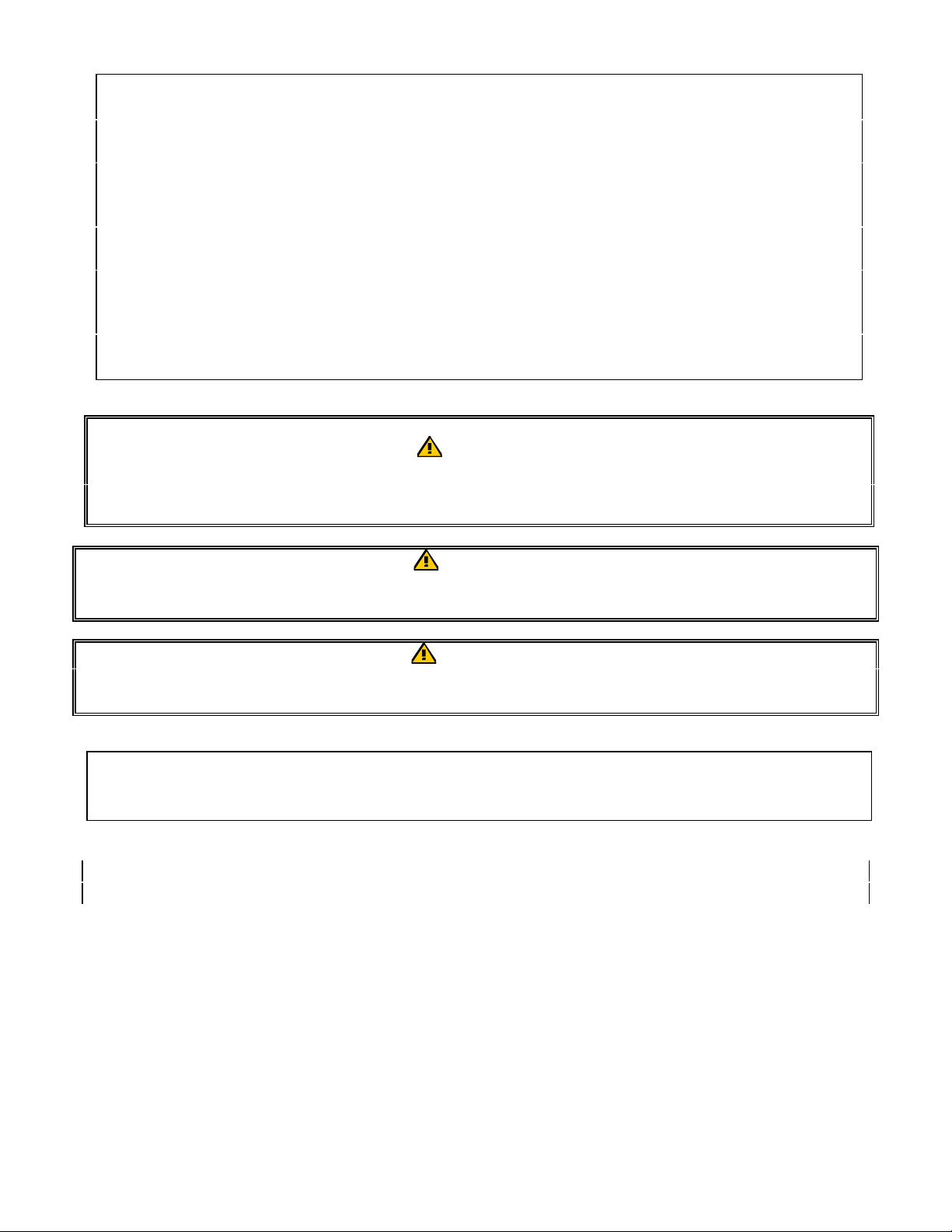
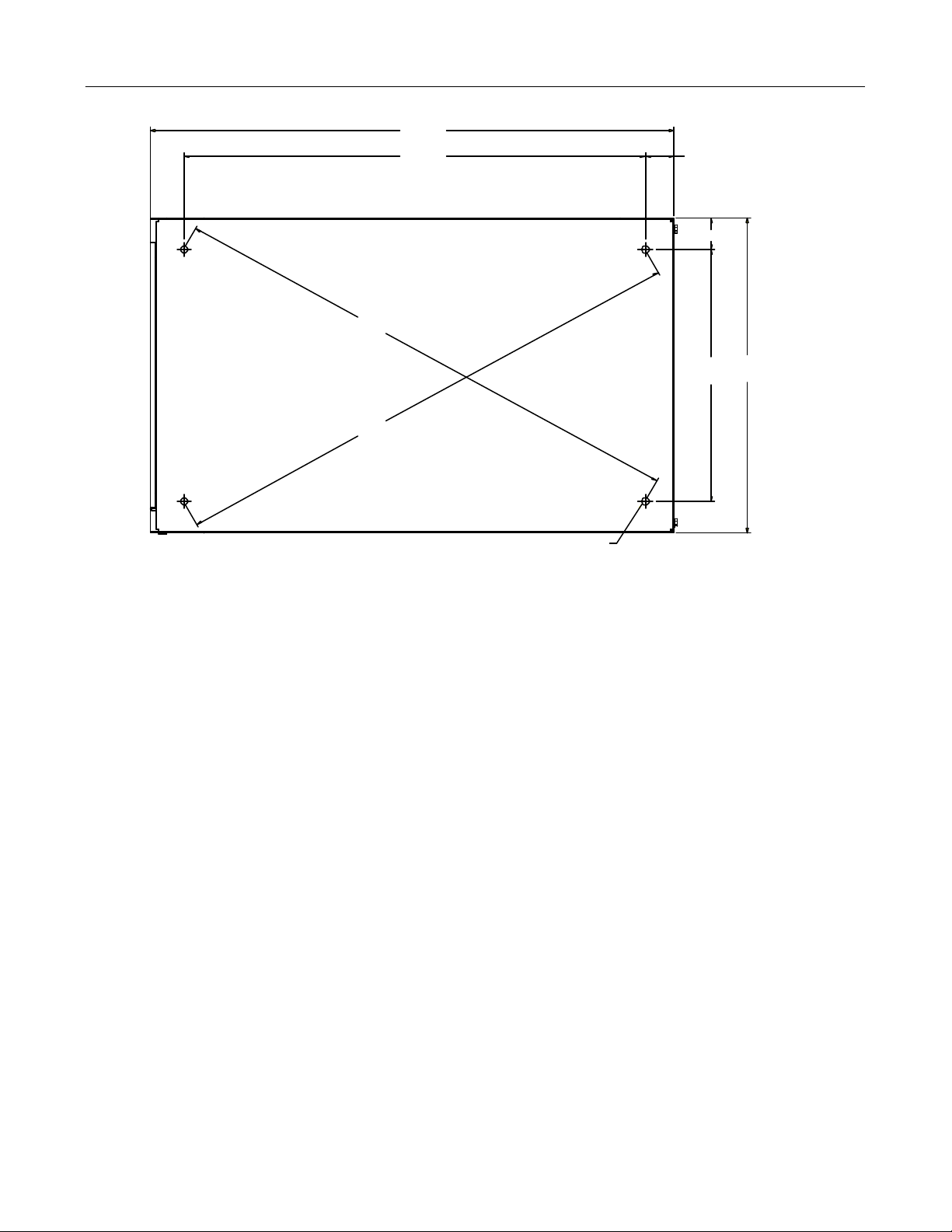
3.1 Fryer Leg Information
The following drawings give the leg patterns for the FPH17 in two, three and four- vat configurations, which are
commonly placed on ships and the single-vat fryer, which is used on submarines. (See Page 3-3, Sub Fryer
base).
CAUTION
If you need to relocate a fryer installed with legs, remove all the weight from each leg before moving.
If a leg becomes damaged, contact your service agent for immediate repair or replacement.
Any flashing on or around the cap covering the top of the heating elements must be removable.
Prior to installation, make sure the foundation is adequate to secure the fryer front and rear. Depending on
existing conditions, most foundations can be modified to suit the fryer’s base plate.
3-1
Page 8
CHAPTER 3: INSTALLATION INSTRUCTIONS
62.55
2.470
7.119
17.490
26.320 31.180
BACK OF FRYER UNIT
31.61 31.61
FPH417
FRONT HANDLE
35.76
35.76
7.119
Mounting Holes
.625
Six Places
33.45
17.516
7.229
27.570 14.400
BACK OF FRYER UNIT
22.68
32.66
22.68
33.24
FPH317
FRONT HANDLE
3-2
Page 9
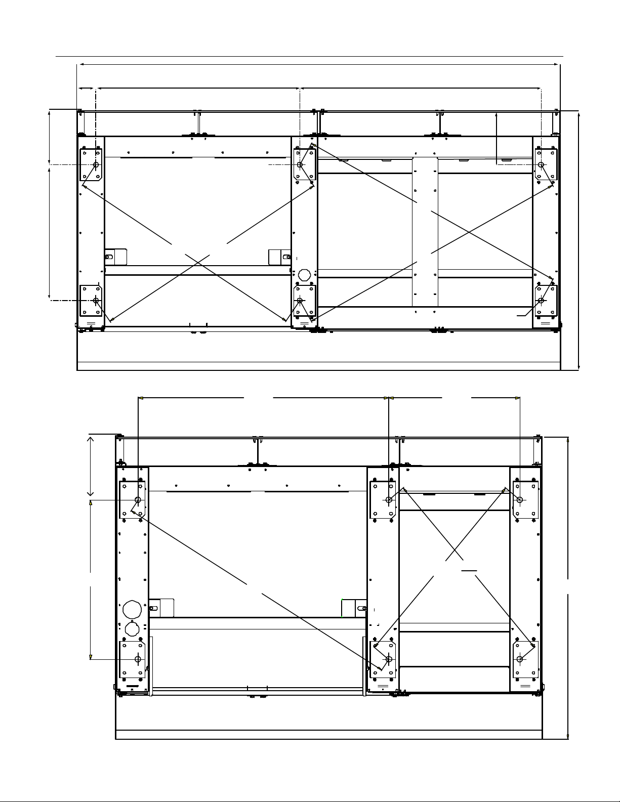
CHAPTER 3: INSTALLATION INSTRUCTIONS
MOUNTING HOLES
Ø .625
4 PLACES
TYPICAL
7.098
TYPICAL
2.470
26.316
BACK OF FRYER UNIT
31.62
31.62
17.515
33.39
15.67
FRONT HANDLE
FPH217
31.45
33.38
28.29
17.534 6.913
2.465
20.48
10.580
20.48
FRONT HANDLE
BACK
OF
FRYER UNIT
H14/17 Single for Surface Ship
3-3
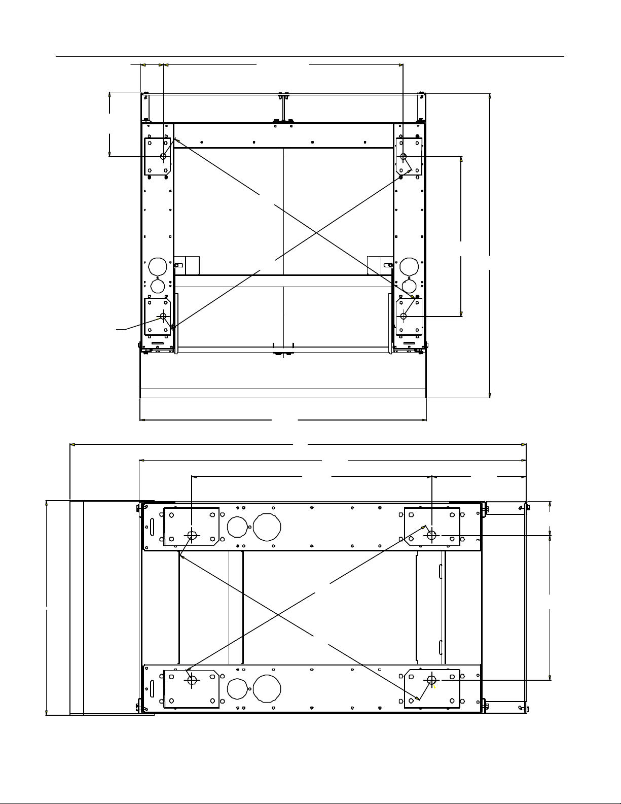
Page 10
Note:
In most
Note:
If nut cannot be secured to bolt
FRONT
CHAPTER 3: INSTALLATION INSTRUCTIONS
25.00
22.00 1.37
1.50
cases, the
contactor box
in a Sub Fryer
25.06
12.00
25.06
will have to be
removed to
secure
15.00
baseplate to
existing
foundation.
MOUNTING HOLES
Navy Sub Fryer
Ø.375
4 PLACES
from deck, the hole will have to be
drilled and tapped.
If it is necessary to install legs, use the instructions provided in the accessories package shipped with
the fryer.
3-4
Page 11
CHAPTER 4: ELECTRICAL SERVICE CONNECTIONS
Connections should be made by means of an approved, flexible-metallic or rubber-covered electrical
cable and quick-disconnect plug. The fryers may be installed with “hard-wired” connections, but use
of quick-disconnect plugs will facilitate service if required. This connection should be made to the
fryer power input terminal block. The terminal block is located in the contactor box in the bottom of
the fryer. CONNECTIONS MUST BE MADE BY QUALIFIED PERSONNEL ONLY AND MEET
NATIONAL AND LOCAL CODES
CAUTION
The fryer(s) MUST be connected to the voltage and phase as specified on the rating and serial number
plate located on the fryer door. To determine the proper wire size and amperage service per fryer, use
the chart on the next page.
CAUTION
A ground wire MUST be connected to the GROUND terminal near the input power terminal block.
CAUTION
Note the following before connecting the fryer to an emergency cutoff system:
• Be sure that each fryer is connected to a dedicated set of contacts in the emergency cutoff system.
• Do not attempt to connect the contacts in series.
• Do not connect more than one fryer to each set of contacts.
• The contacts MUST BE normally closed contacts that open during the emergency.
• The contacts CANNOT have an external voltage applied.
4-1
Page 12
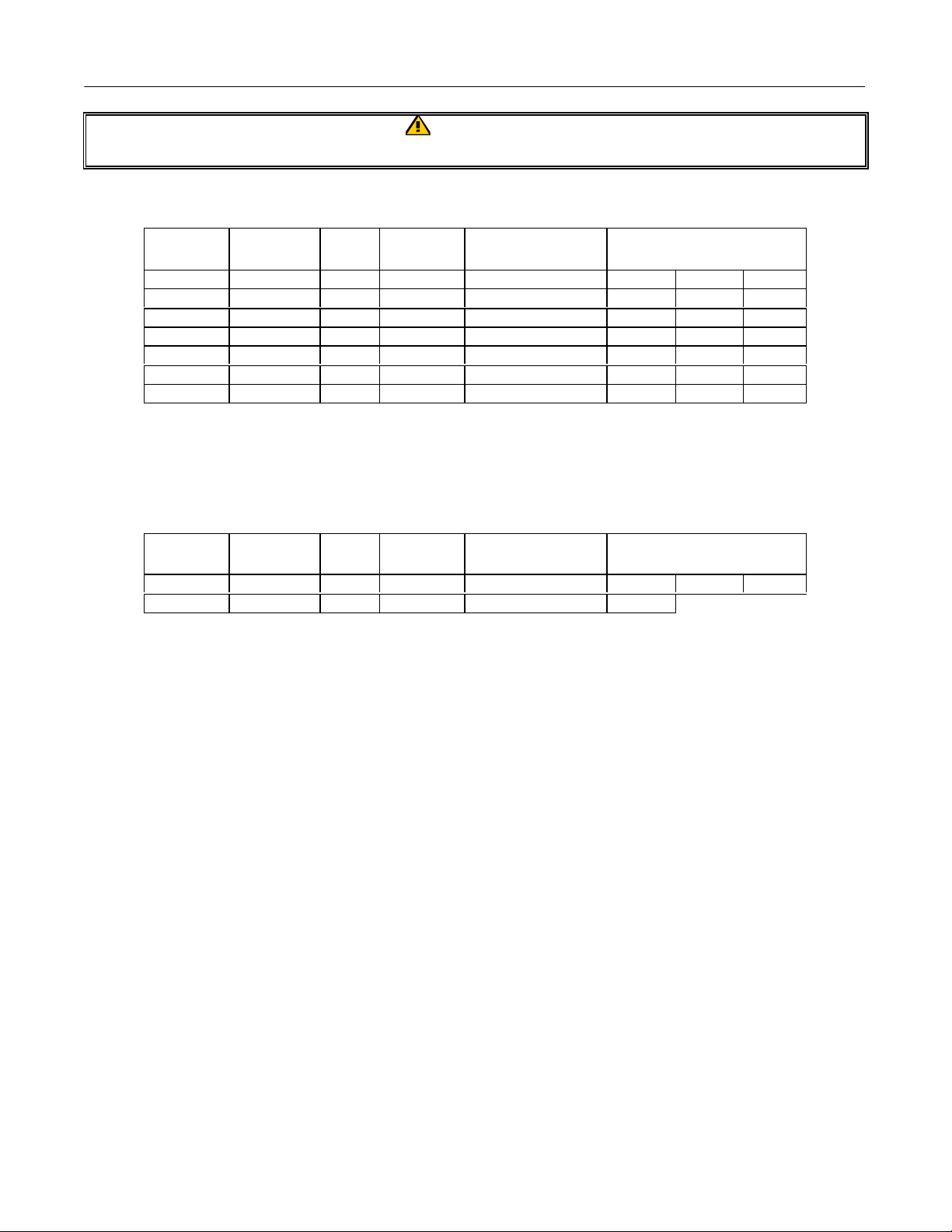
CHAPTER 5: POWER REQUIREMENTS
WARNING
For power supply connection, use copper wire only, suitable for at least 167°F(75°C).
MODEL VOLTAGE PHASE
H14 440 3 3 8 (10) 19 19 19
H14 (Sub) 440 3 3 8 (10) 19 19 19
H14 480 3 3 8 (10) 17 17 17
H17 440 3 3 6 (16) 23 23 23
H17 480 3 3 6 (16) 21 21 21
H22 440 3 3 6 (16) 29 29 29
H22 480 3 3 6 (16) 27 27 27
WIRE
SERVICE
MIN.
SIZE
AWG
(mm2)
AMPS PER LEG
L1 L2 L3
The FPH17 fryer is equipped with a filter system, which requires 120VAC, 20 amp service. The filterequipped fryer also has these power requirements per vat:
MODEL VOLTAGE PHASE
FPH*17 480 3 3 6 (16) 21 21 21
Filter 120 1 3 Standard cord 20
WIRE
SERVICE
MIN.
SIZE
AWG
(mm2)
AMPS PER LEG
L1 L2 L3
* Denotes number of vats. For example, an FPH317 has three vats.
The electrical power supply for the fryers MUST be the same as the voltage
indicated on the rating and serial number plate located on the fryer door.
5-1
Page 13
CHAPTER 6: OPERATING INSTRUCTIONS
6.1. After Fryer(S) Have Been Installed At Frying Station:
NOTE: If you need to relocate a fryer installed with legs, remove all the weight from each leg before
moving. If a leg becomes damaged, contact your service agent for immediate repair or
replacement.
1. Close fryer drain valve(s) and fill frypot with water to the bottom oil level line on the rear wall of
vessel.
2. Boil out frypot(s). See Boil Out instructions on this page.
3. Drain, clean, and fill frypot(s) with cooking oil. See Section 6.3, Filling With Shortening.
4. Check thermostat calibration on fryers with solid-state controller.
6.2 Boiling Out The Frypot:
WARNING
Never run water through built-in filtration system
Clean frypot(s) as follows before filling with cooking oil for the first time and
at least once a month thereafter:
1. Before switching the fryer(s) ON, close the frypot drain valve(s), fill empty frypot with mixture of
cold water and Frymaster Fryer 'N' Griddle Cleaner. Other heavy-duty low sudsing degreaser
compounds may also be used. Follow instructions on bottle when mixing.
2. Press fryer ON/OFF switch to the ON position.
3. Set thermostat knob to 200°F (93°C).
4. Allow the solution to simmer for 45 minutes to one hour. Do not permit the water level to drop
below the bottom oil-level line in frypot during boil-out operation.
5. Carefully monitor the fryer during this time to prevent solution from boiling over.
CAUTION
Do not leave fryer unattended. The boil out solution may foam and overflow if fryer is left unattended.
Press ON/OFF switch to the OFF position to control this condition.
6. Turn the fryer ON/OFF switch(es) to the OFF position.
6-1
Page 14
CHAPTER 6: OPERATING INSTRUCTIONS
7. Add sufficient cold water to lower temperature to a safe level. Drain out the solution and clean the
frypot(s) thoroughly.
8. Refill the frypot(s) with clean water. Rinse the frypot(s) twice, drain and dry inside of pot
thoroughly to remove all residual water.
CAUTION
All drops of water must be removed from frypot before filling with cooking oil.
6.3 Filling With Cooking Oil
Note: Cooking oil/shortening capacity of H14, H17, and H22 Series fryers is 50 lbs. (25 liters) at
70°F (21°C). The capacity of the H14 Submarine fryer is 47 pounds.
Before filling the frypot(s) with cooking oil/shortening:
1. Close the frypot drain valve.
2. Place the power switch(es) to the OFF position.
3. Remove the basket support rack..
4. Fill the empty frypot(s) to the bottom oil-level line.
5. Replace the basket support rack on top of the heating element.
6. Place the ON/OFF switch to the ON position.
7. Set the controller for normal cooking temperature.
6-2
Page 15
CHAPTER 6: OPERATING INSTRUCTIONS
6.4 Before Relocating Fryer for Service
WARNING
Moving a fryer filled with hot cooking oil may cause splattering. Extreme care must be
exercised. It is recommended that the operator or servicer follow the draining instructions of
this manual before attempting to relocate the fryer for service.
If you need to relocate a fryer installed with legs, remove all the weight from each leg before moving.
If a leg becomes damaged during movement, contact your service agent for immediate
repair/replacement.
1. Turn off fryer controller. Disconnect the electrical power from the source.
2. Relocate the fryer for service accessibility.
3. After servicing is complete, return the fryer to the operating position. Reconnect all electrical
power into source. Secure fryers into position. Refill fryer and resume use.
6.5 Shutting Fryer(S) Off
1. Press fryer controller ON/OFF switch(es) to OFF position.
2. Put frypot cover(s) in place over frypot(s).
6-3
Page 16
CHAPTER 6: OPERATING INSTRUCTIONS
6.6 Testing Dual Hi-Limit Controls
Note: Perform this test before replacing old shortening. This high temperature test will greatly
reduce life of new shortening. Start test with the fryer turned ON and with the oil at normal
frying temperature. Stir the oil thoroughly to ensure even distribution and temperature and
place a pyrometer sensing probe in center of frypot about one-inch deep. When verifying oil
temperature, use a pyrometer indicating 0-6000F and a pryometer sensor probe. A high
temperature thermometer may be used instead of a pyrometer.
CAUTION
If the result listed for each step does not occur, turn off fryer at the main circuit breaker panel and do
not use the fryer. Call service agency.
To test the high limit thermostats, proceed as follows:
STEP 1: Press the hi-limit test switch to the 1st hi-limit switch and hold in that position until the
trouble light comes on. The trouble light should come in between 4100F + or - 30F, and
the heating elements must shut off. The HEAT light goes out and the TROUBLE light
comes on. Release the test switch.
STEP 2: Press the hi-limit test switch to the 2nd hi-limit position and hold in that position until the
2nd hi-limit light comes on. It should illuminate between 430°F and 460°F, and the heating
elements must shut off. Release the test switch. All fryers connected to the external shunt
power supply will be shut off completely and all control panel lights will be extinguished.
For fryers not connected to an external shunt power supply, the 2nd hi-limit light will come
on and the fryer will shut off.
STEP 3: Turn power switch to the OFF position.
STEP 3: Allow the cooking oil to cool to below normal frying temperature. When the power switch
is again turned ON, the heaters will turn on and the operating thermostat will resume
control of the temperature. If the red trouble light remains on instead, allow the oil
additional time to cool.
6-4
Page 17
CHAPTER 7: DRAINING AND MANUAL FILTERING
WARNING
Use care when draining and filtering cooking oil/shortening to avoid serious burns.
7.1 Filtering
If you are using a filter other than a FRYMASTER built-in filter system, consult the filter unit
manufacturer’s operating instructions for the recommended procedures. Instructions for using the
FRYMASTER Footprint systems are included in Chapter 16 of this manual.
7.1.a Manual Filtering
The following procedure is recommended to drain and filter your cooking oil/shortening when a filter
machine is not available:
1. Turn the fryer controller power switch to the OFF position. Screw the drain extension pipe
(provided with the fryer) tightly into the drain valve. Make sure the curved end of the tube is
pointing down.
2. Position a metal container with sealable cover under the drain pipe. The metal container must be
able to withstand the hot cooking oil and other hot liquids and be of sufficient capacity to hold
the contents of the frypot. Frymaster recommends that a Frymaster filter cone holder and filter
cone be used when a filter machine is not available. If you are using the Frymaster filter cone
holder and cone, be sure the filter holder rests firmly on the metal container.
3. Open the drain valve slowly to avoid splattering. If splattering occurs, exercise extreme caution.
4. If the drain valve becomes clogged with food particles, use the Fryer’s Friend (poker-like tool).
Use this tool from inside of the frypot ONLY. Grip the tool on the handle as far as possible
from the hot shortening in the frypot. DO NOT HAMMER ON THE DRAIN VALVE, as this
will damage the drain valve ball.
WARNING
Never run water through built-in filtration system.
DANGER
Do not insert the tool into the front of the drain valve to unclog the valve. Hot oil will rush out,
creating an extreme burn hazard!
CAUTION
Allow the shortening to cool to 100°F (38°) or lower before transporting the container and removing
the drain pipe. Exposure to oil at temperatures above 140°F (60°C) can result in severe burns.
5. After draining the oil/shortening, clean all food particles and residual oil/shortening from the
frypot before refilling.
6. Close the drain valve and refill the frypot with clean (or filtered) oil/shortening.
7-1
Page 18
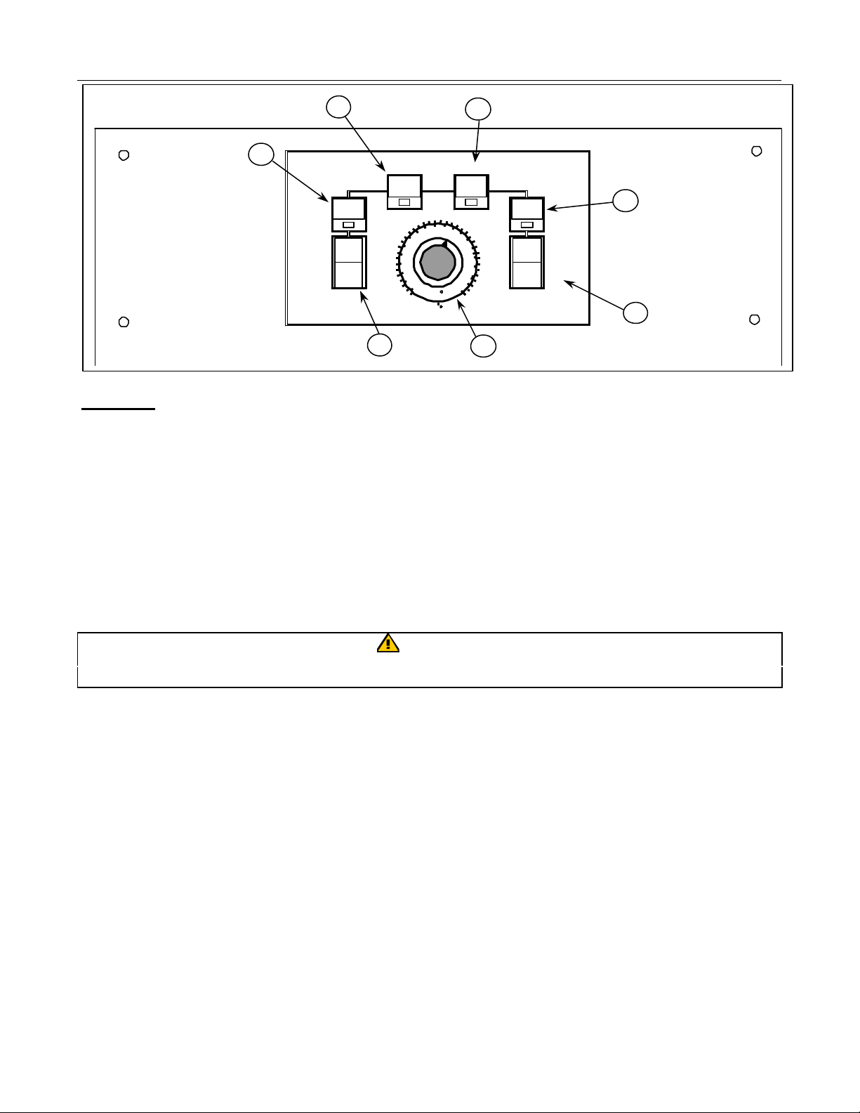
CHAPTER 8: NAVY SHIPBOARD CONTROLLER
Fig. 8-1
4
5
2
TROUBLEHEAT
POWER
ON
POWER
OFF
260
240
220
1
ITEM NO.
1. Power Supply Switch - controls power supply.
2. Power On Light - indicates when electrical power is on.
3. Temperature Control Knob - sets desired frying temperature.
4. Heating Light - indicates element is on.
300
280
130
120
110
100
200
320
140
150
160
340
170
180
360
190
C
F
3
SECOND
2
ND
HI LIMIT
TEST
1
ST
6
7
5. Trouble Light - indicates malfunction of fryer control circuit or overheat condition. Reset by
turning the ON/OFF switch OFF for 30 seconds, then ON.
6. Second High-Limit Light – indicates fryer has overheated and the high limit has shut fryer off.
7. High-Limit Test Switch – Tests high-limit thermostats.
CAUTION
Fryer must be filled with oil, shortening, or water before turning on controller.
8.1 Temperature Calibration
1. Insert a good grade thermometer or pyrometer probe into the cooking oil/shortening near the fryer
temperature-sensing probe.
2. Turn thermostat knob to frying temperature.
3. Let elements cycle on and off automatically three times to allow the cooking oil temperature to be
uniform.
4. When the elements start for the fourth time, the pyrometer reading should be within 5°F (2°C) of
the thermostat knob setting. If it is not, calibrate as follows:
a. Loosen set screw in thermostat control knob until outer shell of knob will rotate on insert inside
knob.
b. Rotate outer shell of knob until index line on knob aligns with marking that corresponds to
thermometer or pyrometer reading.
c. Hold knob and tighten set screw.
8-1
Page 19

CHAPTER 8: NAVY SHIPBOARD CONTROLLER
Press and hold rocker switch down
d. Recheck the thermometer or pyrometer reading and the thermostat knob setting the next time
the elements come on.
e. Repeat Steps 4.a. through 4.d. until thermometer or pyrometer reading and knob setting agree
within 5°F (2°C).
f. If calibration cannot be obtained for any reason, call a Factory Authorized Service Center.
5. Remove thermometer or pyrometer probe.
8.2 Hi-Limit tests
Hi-limit 1 checks the ability of the fryer’s controller to shut down
the fryer.
The test is conducted with the oil at or near operating temperature.
Hold the Hi-limit rocker switch in the 1st position.
The oil will heat to 4100F +- 30F degrees before the controller stops
calling for heat. The trouble light will illuminate just at the heat
light goes out.
Reset the fryer by turning the unit off and back on at the control
panel.
Hi-Limit 2 checks the ability of the fryer’s mechanical hi-limit
probe to shut down the fryer. To run the test, hold the rocker
switch in the 2nd position. With the rocker depressed, the oil will
heat to 430-4500F degrees before the mechanical hi-limit probe
opens, which shuts off power to the fryer.
Fig. 8-2
for Hi-Limit 1 test. Hold the switch
up for the second hi-limit test.
8-2
Page 20

CHAPTER 9: TROUBLESHOOTING GUIDE
Directions for Troubleshooting Flow Chart
1. Always start at the first condition and follow each step in sequence.
2. Perform the test set-up at the beginning of each condition.
3. Normal Operation (“yes” after each decision block) flows down the page in sequence.
4. Abnormal Operation (a “no” answer) branches to the right side of the page where you will find the steps
for problem resolution.
Warning:
Inspection, testing and repair of electrical equipment should be performed by qualified service
personnel. Unplug the unit before servicing, except when electrical test are required.
DANGER
USE EXTREME CARE DURING ELECTRICAL CIRCUIT TESTS. LIVE CIRCUITS WILL BE
EXPOSED.
Note: Access to the interface board is required to
perform troubleshooting. See Figures 10-6 and 10-7.
Fryer is Off
Using interface board
lights to diagnose fryer.
Press the ON/OFF
Switch to OFF
Is
CMP light
Interface board on?
Is
24V Light
Interface board on?
All other lights
on
YES
on
YES
off?
NO
NO
NO
1. No power applied to fryer from power supply.
2. Defective 12 volt transformer.
3. Defective interface board ( 12 VAC circuit).
4. Broken or improper wire connection.
5. Blown fuse.
1. Defective 24 volt transformer.
2. Defective interface borard (24 volt circuit).
3. Broken or improper wire connection.
4. Blown fuse.
1. Defective controller.
2. Improper wire connection.
YES
Condition is
normal
9-1
Page 21

CHAPTER 9: TROUBLESHOOTING GUIDE
Turning Fryer On
Fryer fails to heat
the oil.
Fryer is on and the
thermostat is set at least 45
degrees above the
temperature of the cool oil.
Yes
Are the power and heat
lights on the controller on?
Yes
NO
1. Trouble light ON indicates
a. Oil temperature is above the accepted range.
b. Problem in temperature measuring circuit (including probe).
2. Heat light and trouble light on indicates a latching circuit problem.
3. Defective controller.
4. Broken or improper wire connection.
Is 24 Volt light on interface
board lit?
Yes
Right HI light on
interface board on?
Yes
24 volts supplied to
latching contactor coil;
contactor activates?
Yes
NO
NO
1. Problem in 24-volt circuit.
1. Open high limit.
2. Open drain valve microswitch.
3. Broken or defective wiring connection.
1. Defective latching relay.
2. Broken or improper wire connection.
3. Defective interface board.
NO
4. Defective latching contactor.
As controller heat light
illuminates, interface HT light
comes on?
(Continued on Page 9-3)
1. Defective heat relay.
NO
2. Broken or improper wire connection.
3. Defective interface board.
4. Defective control.
9-2
Page 22

CHAPTER 9: TROUBLESHOOTING GUIDE
Fryer Fails to Heat
Yes
24 volts supplied to heat
contactor and heating
contactor closes?
Yes
Do the elements heat
and draw proper amps?
Yes
Do elements continue to
heat and maintain proper
temperature?
( Continued from Page 9-2 )
1. Defective heating contactor.
No
2. Broken or defective wiring connection.
3. Defective interface board.
No
No
1. Defective heating contactor.
2. Defective heating element.
3. Broken or defective wire connection.
4. Improper wire connection.
Unit stops heating with heat light on.
Defective or improperly installed high-limit.
Defective heating or latching contractor.
Unit heats until high limit trips without heat light on.
Defective (shorted or grounded) heating element.
Defective (sticking) temperature probe.
Defective controller.
Bad harness, wire connections.
Yes
Fryer operating
normally.
9-3
Page 23

CHAPTER 10: SERVICE PROCEDURES
Fig: 10-2
Fig: 10-3
10.1 Replace Controller
10.11 Shipboard fryer
1. Disconnect the fryer from electrical power.
2. Turn controller off.
3. Remove the two screws securing the controller.
4. The controller is hinged at the bottom, and will swing
open from the top.
5. Unplug the wiring harness from the back of the
controller. Fig: 10-1
6. Remove the ground wire by unscrewing the securing
nut or disconnecting the ground connector.
7. Remove the controller from the control panel.
8. Reverse the procedure to install a new controller.
10. 12 Submarine Fryers
1. Disconnect the fryer from electrical power.
2. Turn the controller off.
3. Remove the two screws securing the
controller bezel to the front of the fryer. Fig
10-2.
4. Pull the controller forward and under the grab bar.
5. Remove the two screws that secure the lower
section of the bezel.
6. Unplug the controller from the 15-pin plug.
Fig: 10-1
Unplug wiring harness from back of controller.
Two screws secure
the controler bezel
to the fryer’s front
Two screws hold
the bezel inside the
cabinet.
7. Push the controller forward and under the
grab bar. Fig 10-3
8. Remove the heat shield from at the rear of
the controller. Fig: 10-4
9. Remove controller from bezel.
10. Reverse procedure to install new controller.
Fig: 10-4
A shield, which must be removed, protects
the controller from heat.
10-1
Page 24

CHAPTER 10:
SERVICE PROCEDURES
Fig: 10-5
Control box screws.
Drain
box lid.
box behind the controller.
Screw that
10.2 Replace Interface Board
10.2.1 Surface Ship Fryers
1. Disconnect the fryer from electrical power.
2. For surface ship fryers perform Section 10.1, Steps 1-
6, Replace Controller.
3. Unplug the wire harness from the interface board. Fig
10-1. Remove all wiring from the interface board,
carefully marking wires for correct reattachment.
NOTE: If fryer is part of a battery of two or more fryers, the control panel and top cap are one piece,
and must be removed as one piece.
4. Remove the screws securing the control panel.
5. Remove the screws securing the top cap, and set the top
cap and screws aside.
6. Remove the screws securing the component box. Let the
top of the box swing forward enough so that the wire
harness can be unplugged from the back of the interface
board. Fig: 10-6
7. Remove the nuts from each corner of the interface board
and slide the board from the studs.
Control panel mounting screws.
Fig: 10-6
The interface board on the surface
ship fryer is located in the controller
8. Install the new interface board by reversing the above procedures. Ensure the spacers are on the
studs before installing the interface board. Make sure the wiring is reconnected to the proper
terminals and the harnesses to the correct connectors.
10.2.2 Submarine Fryers
1. Disconnect the fryer
from electrical power.
2. Open the front door of
the fryer, and remove
the screw holding the
contactor box lid in
place. Fig: 10-8
Fig: 10-8
Hold-down
screw for
contactor
3. Slide lid from cabinet.
4. Unplug the wire
harnesses from the front
and back of the interface
board.
Fig: 10-7
The interface board is in the
contactor box in the sub fryer.
10-2
15-pin plug for controller.
secures
contactor
box in
cabinet.
elbow
Page 25

CHAPTER 10:
SERVICE PROCEDURES
5. Remove the nuts from each corner of the interface board and slide the board from the studs. Fig:
Fig: 10-10
10-7
6. Install the new interface board by reversing the above procedures. Ensure the spacers are on the
studs before installing the interface board. Make sure the wiring is reconnected to the proper
terminals and the harnesses to the correct connectors.
10.3 Replace Transformer
10.3.1 Surface Ship Fryers
1. Disconnect the fryer from electrical power.
2. Perform Section 10.1, Steps 1-6, Replace Controller.
3. Remove all wiring from the terminals of the transformer to be
replaced, carefully noting where the wires are attached. Fig: 10-9
4. Remove the transformer mounting nuts.
5. Install the new transformer by reversing the procedure. Make sure
the wires are correctly connected to the proper terminals.
10.3.2 Submarine Fryers
On the surface ship fryer, the
transformer is in the controller box.
Fig: 10-9
1. Drain frypot and close drain valve
2. Disconnect the fryer from electrical power.
3. Remove elbow from drain.
4. Open the front door of the fryer, and remove screw
holding contactor box in place. Fig: 10-8
5. Remove door magnet to ensure space to pull contactor box
forward.
6. Push contactor box toward the rear of the fryer and lift to
release it from clips in the rear.
7. Lift the front of the contactor over the mounting hardware
and pull forward out of the cabinet the distance the wiring
harness will allow. Fig: 10-10
8. Remove screw holding the lid on the contactor box.
9. Remove all wiring from the terminals of the transformer to
be replaced, carefully noting where the wires are
attached.
10. Install the new transformer and attach wires.
Contactor box partially removed from the
11. Reverse steps to complete installation.
10-3
Page 26

CHAPTER 10:
SERVICE PROCEDURES
10.4 Replacing Temperature Probe
Tilt-plate
Fig: 10-12
1. Disconnect electrical power to the fryer.
2. Drain the cooking oil from the frypot.
3. Remove cap over elements.
4. Disconnect the wiring harness, which is visible inside the cabinet, containing the red and white
probe wiring. It may be necessary to remove the wire ties.
Red & white
probe wires
Black high-limit
wires.
Fig: 10-11
hole
Probe clip
Temp
probe and
bracket
Fig: 10-13
Hardware on fixed elements
in sub fryer.
5. Use a pin pusher (Frymaster Part Number 806-4855) to remove the probe wires from the
connector. Mark each wire for re-assembly. Fig: 10-11
6. Remove the screw(s) securing the probe bracket to the element. Fig: 10-12
7. Thread the wires through the hole in the tilt plate assembly on the surface ship fryers and through
the access hole near the fixed elements on the sub fryer. Fig: 10-13. Remove the probe and the
securing components from the element.
8. Remove the probe from the probe bracket, and place the new probe into the bracket.
9. Place the new temperature probe assembly onto the element and secure with the screws. Clip the
probe onto the rear of the element. The temperature probe assembly should be oriented in the
same manner as the probe being replaced.
10. Thread the probe wires into the harness connector as removed in Steps 6 & 7.
11. Lower the element into the frypot. (surface ship only).
12. Place the housing cover over the element housing assembly and secure with screws.
10-4
Page 27

CHAPTER 10:
SERVICE PROCEDURES
10.5 Replace Heating Element
Fig: 10-15
10.51 Surface Ship
1. Remove temperature probe per Section 10.4, Steps 1-5, and step 8.
2. Unplug element wire plugs from rear of contactor box. It may be necessary to pull the contactor
box forward to reach the connectors.
3. Remove the heating element wires from the connector. Press down on either side of the connector
while pulling up on the top portion. The connector will open from the top, releasing the wires.
Pull all wires from the connector, noting wire locations in the connector for re-assembly.
4. Remove the temperature probe clamp. Set temperature probe and bracket components aside.
5. Disconnect the element springs. Fig: 10-14
Fig: 10-14
Element springs on surface ship fryer.
Element mounting screws on surface ship fryer.
6. Remove the element mounting screws and pull the element out of the frypot. Fig: 10-15
7. If present, remove the lift handle from the old element and install it on the new one.
8. Install the temperature probe and probe-securing components onto the replacement element.
9. Install the replacement element in the frypot and secure with mounting screws removed in Step 6.
10. Route the element leads (terminals) to the rear of the frypot.
11. When replacing the left element (as viewed from the front of the fryer) insert pin terminals into
the correct holes in the 6-pin connector. When all pins are fully inserted, close the connector by
sliding the halves together until the tabs snap back into place.
12. When replacing the right element (as viewed from the front of the fryer), use the 9-pin connector.
Follow the steps outlined in Step 11.
13. Insert the connector(s) into the receptacle(s) in the rear of the contactor box. Be sure the latches
lock the connectors in place.
14. Install the temperature probe wires into the corresponding pin locations.
15. Reconnect the element spring.
16. Install the tilt housing assembly.
10-5
Page 28

CHAPTER 10:
SERVICE PROCEDURES
17. 10.5.2 Submarine
Left element
Temp, hi-limit
1. Disconnect electrical power to the fryer.
2. Drain the cooking oil from the frypot.
3. Remove drain system elbow.
4. Remove screw holding contactor box in place. Fig: 10-8
5. Lift contactor box at rear and push backward slightly to
disengage tabs which secure the rear of the box.
Fig: 10-16
6. Lift front of contactor box and pull it forward to create
Mounting hardware on fixed-element sub fryer.
working room at the rear of the box to remove element
connectors.
7. Unplug two lower plugs. Fig: 10-17
8. Remove temperature probe per Section 10.4, Steps 1-5, and step 8.
9. Remove mounting hardware on heating elements and lift from unit. Fig: 10-16
10. Remove the heating element wires from the connector. Press down on either side of the connector
while pulling up on the top portion. The connector will open from the top, releasing the wires. Pull
all wires from the connector, noting wire locations in the connector for re-assembly.
11. Install the temperature probe and probe-securing components onto the replacement element.
12. Install the replacement element in the frypot and secure with mounting screws removed in Step 9.
13. Route the element leads (terminals) to the rear of the frypot.
14. When replacing the left element (as viewed from the front of the fryer) insert pin terminals into the
correct holes in the 6-pin connector. When all pins are fully inserted, close the connector by
sliding the halves together until the tabs snap back into place.
15. When replacing the right element (as viewed from the front of
the fryer), use the 9-pin connector. Follow the steps outlined
in Step 11.
16. Insert the connector(s) into the receptacle(s) in the rear of the
contactor box. Be sure the latches lock the connectors in
place.
17. Install the temperature probe wires into the corresponding pin
locations.
18. Feed wires down back of fryer and plug into receptacles on
rear of contactor box.
Right element
connector
Fig: 10-17
connector
connector
19. Restore contactor box to its original position, replace element
cap and replace drain elbow.
20. Fill with oil and return fryer to operation.
10-6
Page 29

CHAPTER 10:
SERVICE PROCEDURES
10.6 Replace High-Limit Thermostat
lifted from the cabinet.
Fig: 10-18
1. Drain frypot.
2. Remove drain elbow from drain assembly.
3. Remove screw securing contactor box in place. Lift the contactor box
and push back slightly to release tabs holding the box in the rear of
the cabinet. Lift and pull the box forward to allow access to the plugs
at rear of unit. Fig: 10-8
4. Unplug 15-pin plug from front of contactor box (sub fryer only).
5. Unplug the three plugs on the rear of the contactor box.
6. Remove the element cap.
7. Remove two screws securing controller bezel to fryer’s
frame and pull controller forward to access lower screws.
8. Remove lower bezel screws.
9. Remove controller.
10. Remove screw at front of fryer that holds frypot in place.
Fig: 10-19.
11. Lift frypot from cabinet.
12. Disconnect the wiring harness containing the high-limit
wires.
13. Use a pin pusher (Frymaster Part Number 806-4855) to remove the two high-limit wires from wire
harness connector C6. For split pot fryers, remove only the wires for the high-limit to be replaced.
Mark each wire for re-assembly. Fig: 10-11
14. Use a 7/8” wrench to remove the high-limit thermostat from the frypot.
15. Apply LocTite PST 567 sealant (enclosed with replacement high -limit) to the threads of the new
high-limit thermostat.
The removal of one screw behind
the controller allows the frypot to be
Hi-limit probe
Fig: 10-19
16. Screw the new high-limit into the frypot and tighten securely. DO NOT OVERTIGHTEN!
17. Rest frypot on cabinet sideways, allowing wires to hang near the back of unit.
18. Insert the replacement high-limit wires into the holes in the connector, making certain to insert the
pins into the same two holes from which the old high -limit wires were removed.
19. Position frypot in cabinet
20. Reconnect element wire harnesses to contactor box.
21. Restore contactor box to original location.
22. Replace drain elbow.
23. Replace controller and plug into 15-pin socket on front of contactor box.
24. Install the rear flue covers.
25. Return to service
10-7
Page 30

CHAPTER 10:
SERVICE PROCEDURES
10.7 Replace Frypot
1. If the fryer has a built-in oil filtration system, remove all the plumbing from the frypot. This
includes both oil return and drain fittings.
2. Perform Section 10.6 steps 1-11
3. Remove elements.
4. Remove hi-limit.
5. Apply LocTite PST 567 sealant to the threads of the
existing or new high-limit thermostat.
6. Screw the high-limit into the frypot and tighten
securely. DO NOT OVERTIGHTEN!
7. Install elements.
8. Rest frypot on cabinet sideways, allowing wires to hang
near the back of unit.
9. Insert the high-limit wires into the holes in the connector, making certain to insert the pins into the
same two holes from which the old high -limit wires were removed.
10. Position frypot in cabinet
11. Reconnect the wire harnesses to contactor box.
Fig: 10-20
Fig: 10-21
12. Restore contactor box to original location.
13. NOTE: Apply LocTite PST 567 sealant to all pipe connections prior to assembly.
14. Replace drain elbow.
15. Replace oil return lines on units with built-in filtration.
16. Replace controller and plug into 15-pin socket on front of contactor box.
17. Install the rear element cover.
18. Boil out new frypot as described on page 6.1
19. Return to service
10-8
Page 31

CHAPTER 10:
SERVICE PROCEDURES
10.8 Replace Heating or Latching Contactor
1. Disconnect electrical power to the fryer.
2. Drain the cooking oil from the frypot.
3. Remove cap over elements.
4. If present, remove the wire harness connector covers on the front of the contactor box.
5. Disconnect the 15-pin controller plug from the front of the contactor box, Remove screw securing
contactor box in place. Lift the contactor box (Fig: 10-8) and push back slightly to release tabs
holding the box in the rear of the cabinet. Lift and pull the box forward to allow access to the plugs
at rear of unit.
6. Remove the screws securing the contactor. (See drawing on page 16-3)
7. Remove wiring connected to the contactor terminals. Mark wires for re-assembly
8. Remove the contactor mounting screws and contactor.
9. Install new contactor and attach wiring.
10. Reverse Steps 1-7 to complete job.
10-9
Page 32

CHAPTER 11: PREVENTIVE MAINTENANCE
11.1 Clean Inside And Outside Of Fryer Cabinet - Daily
Clean inside the fryer cabinet with a dry, clean cloth. Wipe all accessible metal surfaces and
components to remove accumulated cooking oil and dust.
Clean outside the fryer cabinet, with a clean, damp cloth soaked with dishwashing detergent. Wipe
with a clean, damp cloth.
11.2 Once A Week - Clean Frypot And Heating Elements
WARNING
NEVER operate the fryer(s) with an empty frypot.
BOILING OUT THE FRYPOT: Clean frypot as follows before filling with cooking oil:
1. Before switching the fryer(s) ON, close the frypot drain valve(s), fill empty frypot to the normal
level with a mixture of water and Frymaster Fryer 'N' Griddle Cleaner or other low sudsing
degreasing compound. Follow instructions on bottle when mixing.
2. Press fryer ON/OFF switch to the ON position.
3. Set thermostat knob to 200°F (93°C).
4. Allow the solution to simmer for 45 minutes to one hour. Do not allow water level to drop below the
bottom oil-level line in frypot during boil-out operation.
CAUTION
Do not leave fryer unattended. The boil-out solution may foam and overflow if fryer is left
unattended. Turn controller OFF to control this condition.
5. Turn the fryer controller power switch to the OFF position.
6. Add enough cool water to permit draining without danger of burning. Drain out the solution and
clean the frypot(s) thoroughly.
WARNING
Do not run water/boil-out solution through filtration system.
7. Refill the frypot with clean water. Rinse the frypot twice, drain and wipe down with a clean, dish
towel. Thoroughly remove all water from the frypot and elements before filling the frypot with
cooking oil.
11.3 Once A Week - Clean Detachable Parts And Accessories
Wipe all detachable parts and accessories with a clean, dry cloth. Use a clean cloth saturated with
Frymaster Fryer 'N' Griddle Cleaner to remove accumulated carbonized oil on detachable parts and
accessories. Rinse the parts and accessories thoroughly with clean water and wipe dry before
reinstalling.
11-1
Page 33

CHAPTER 11: PREVENTIVE MAINTENANCE
11.4 Once A Month -
Check Calibration Of Controller
1. After the cooking oil has reached operating temperature, let the heating elements cycle at least 4
times.
2. Insert a good thermometer or pyrometer near the temperature-sensing probe approximately 3 inches
(7.5mm) deep into the cooking oil. When the heating elements just cycle on after the fourth time,
the thermometer should within ±5°F (±2°C) of the thermostat knob setting.
3. See the controller calibration section of the service manual.
11-2
Page 34

CHAPTER 12: OIL FILTRATION (Surface Ship Only)
Fig: 12-1
Removing filter pan prior to cleaning.
Fig: 12-2
Fig: 12-3
DANGER
Exercise extreme care when working with hot cooking oil. Allow the filter pan to completely cool
before attempting to change the filter paper.
WARNING
Never run water through built-in filtration system
12.1 Preparing The Filter Unit For Use
1.Turn the vat off you intend to filter.
2. Open cabinet and remove filter pan. It must be cleaned prior to
filtering. Fig: 12-1
3. The filter pan holds a crumb screen, hold-down ring and filter
paper or a filter pad. All must be removed and cleaned.
4. The crumb screen comes out first. This catches the large food
particles in the filtering process. Fig: 12-2
5. Remove hold-down ring, which holds the filter paper or filter pad
in place. Fig: 12-3
6. Remove filter paper or pad and discard.
Removing crumb basket.
Removing hold-down ring.
12-1
Page 35

CHAPTER 12: OIL FILTRATION (Surface Ship Only)
Fig: 12-5
Fig: 12-4
Remove screen from filter pan.
7. Remove screen from filter pan. Fig: 12-4
8. Clean filter pan. Fig: 12-5
9. Replace screen.
10. Replace filter pad or paper.
11. Replace hold-down ring.
12. Replace crumb screen. Fig: 12-8
Clean pan.
Fig: 12-6
Replace screen. It’s imperative the screen goes
in the pan first. It goes under the filter paper or
pad. The filter paper or pad must go on top.
Fig: 12-7
The filter paper goes on top of the screen.
Add 8-ounces of filter powder to the top of
the filter paper. Do not use filter powder
Fig: 12-8
The hold-down ring is placed on the filter
paper and the crumb screen is put in place.
12-2
Page 36

CHAPTER 12: OIL FILTRATION (Surface Ship Only)
Fig 12-14
Drain
Filter
With the oil above 300 degrees, move
13. Return filter pan to cabinet.
14. Skim large particles from the vat to be
filtered.
14. With the oil at operating temperature and
the fryer off, open valve of vat to be drained.
Caution: the oil is at or near operating
temperature during filtering. Fig: 12-14, 16
16. Snap the power shower into the frypot
connection. Fig: 12-15
17. For fryers with rear flush option, engage
the control lever to select rear flush. This
will wash sediment from the bottom of the
frypot.
18. Turn the filter pump on. Fig: 12-17
19. The oil is pumped back into the frypot. If
polishing of the oil is desired, allow pump to
run with the drain valve open for no more than
Handles used during filtering:
valves
five minutes.
20. At the end of the filter process, close the
drain and allow the pump to run as the oil fills
up the frypot.
21. When the filter pan empties, air will be pumped into the frypot, causing the oil in the frypot to bubble.
Allow bubbling to continue 15 to 20 seconds before shutting off
filter pump. This action ensures the oil-return lines are clear of
oil.
22. Remove Power Shower. Fig: 12-15
pump
handles
Fig: 12:15
A Power Shower is shown being
placed in a frypot. Filtered oil returning
to the frypot flows through the device
and down the sides of the vessel,
cleaning the pot walls.
Fig: 12-16
the handle to the right to empty the
frypot into the filter pan.
Fig: 12-17
The filter pump
moves oil from
the drain pan to
the frypot.
12-3
Page 37

CHAPTER 12: OIL FILTRATION (Surface Ship Only)
DANGER
Never attempt to remove a filter pan containing hot cooking oil/shortening. Hot oil/shortening will flow
through the outlet in the bottom of the pan and cause severe burns to feet and legs.
CAUTION
Never operate the filter unit unless the cooking oil/shortening in the fryers has been brought up to cooking
temperature.
NOTE: Exercise care when using the Fryer's Friend to prevent damage to the frypot and the drain valve.
Do not drain more than one frypot at a time. To do so will cause overfilling of the filter pan.
DANGER
Except when using the rear flush option, do not operate without power shower. Hot cooking oil/
shortening can splash and cause injury.
NOTE: Filter motor is equipped with a manual reset switch in case the filter motor overheats or an
electrical fault occurs.
CAUTION
Turn off power to the filter system and allow pump motor to cool 20-30 minutes before attempting to
reset switch on the pump motor
WARNING!
The crumb tray must be emptied into a fireproof container at the end of each day. Some food
particles can spontaneously combust if left in certain shortening.
12-4
Page 38

CHAPTER 13
CARE AND CLEANING OF THE FILTER SYSTEM
DANGER:
WARNING:
NEVER use the filter pan to dispose or
transport old cooking oil/shortening to the
disposal area.
Never operate the filter system without
cooking oil in the system.
Always allow cooking oil to cool below 100°F (38°C) before transporting to the disposal area. A
Shortening Disposal Unit (SDU), available from your local distributor, is available and highly
recommended for safety.
1. Do not drain water into the filter pan. Water will damage the filter pump. Perform the following
to drain the frypot:
A. Footprint III
1) Pull the filter carriage forward.
2) Remove the empty filter pan assembly.
3) Push the filter carriage back into the fryer.
4) Place suitable container under the drain.
5) Open the drain valve.
A. Footprint III - the o-ring is on the bottom of
the filter pan.
3. Immediately after use, drain the power shower completely. If you suspect blockage, unscrew the
plugs at each corner of the power shower frame. Use a long narrow bottle brush with hot water
and detergent to clean the inside of the power shower. Rinse, dry thoroughly, and reinsert plugs
before using.
Page 39

CHAPTER 13
CARE AND CLEANING OF THE FILTER SYSTEM
13.1 Filtration Problems
One of the most common errors is placing the filter
paper on the bottom of the filter pan rather than on
top of the filter screen.
Whenever the complaint is “the pump is running,
but no oil is returning,” check the installation of the
filter paper, and ensure that the correct size paper is
being used. While you are checking the filter
paper, verify that the o-ring on the bottom of the
filter pan (and on the suction tube if applicable) is
present and in good condition. A missing or worn
o-ring allows the pump to suck air and decrease its
efficiency.
The filter screen must go in the bottom of the pan
first. The filter paper goes on top of the screen.
For Filter Magic Systems, if the pump runs, but does not return oil, the most likely causes are that the
filter carriage is not properly positioned all the way to the rear of the fryer or the suction tube o-rings
are missing or worn.
If the pump motor overheats, the thermal overload will trip and the motor will not start until it is
reset. If the pump motor does not start, press the red reset switch located on the end of the motor.
If the pump then starts, something caused the motor to overheat. If the motor runs for a prolonged
period, it may overheat. Allow the motor to cool down for at least 30 minutes and press the reset
button.
The pump may also overheat for one of the fo llowing reasons:
• Shortening solidified in the pan or filter lines.
• The operator attempted to filter oil or shortening that was not heated. Cold oil and shortening are
thicker and cause the pump motor to work harder and overheat.
If the pump will not return oil and you hear a humming sound just before the overload trips, the pump
is blocked. Paper which is incorrectly sized or installed will allow food particles and sediment to
pass through the filter pan and into the pump. When sediment enters the pump, the gears may bind
causing the motor to overload, tripping the reset circuit breaker. Solidified shortening in the pump
may also prevent it from turning, with the same result.
Page 40

CHAPTER 13
CARE AND CLEANING OF THE FILTER SYSTEM
FREEING A SIEZED PUMP
Freeing a Seized Pump
Sediment Particle
Up for reverse
Down for forward
A pump seized by debris or hard shortening can usually be freed by manually moving the gears with
a screwdriver or other instrument.
1. Disconnect power to the filter system.
2. Remove the input plumbing from the pump.
3. Use a screwdriver to manually turn the gears.
• Turning the pump gears backward will release a hard particle.
• Turning the pump gears forward will push softer objects and solid shortening through the pump
and allow free movement of the gears.
Incorrectly sized or installed paper will also allow food particles and sediment to pass through and
clog the suction tube on the bottom of the filter carriage. Particles large enough to block the suction
tube may indicate that the crumb tray is not being used.
Pan blockage can also occur if shortening is left in the pan and allowed to solidify. The heater strip
on the suction tube is designed to prevent solidification of residual shortening left in the tube. It will
not melt or prevent solidification of shortening in the pan.
A blockage can be removed by forcing the item out with a stiff wire or drain snake. Compressed air
or other pressurized gases should not be used to force out the blockage.
Possible problems with the Power Shower include clogged openings, solidified shortening or debris
in the tubes, missing clean-out plugs, and missing or worn O-rings. Cleaning the unit and replacing
missing plugs and missing or worn O-rings will correct these problems.
The electronics of the filter system are simple and straightforward. Micro-switches, attached to
handles for each vat and wired in parallel, provide the 24 VAC required to energize the pump relay
coil when the oil return handles are moved to the ON position. The energized pump relay supplies
the power to the pump motor.
The suction tube heater and flexible hose heater are wired directly into the 24 VAC source. They
remain energized as long as the unit is plugged into an outlet.
Page 41

CHAPTER 13
Return Micro
CARE AND CLEANING OF THE FILTER SYSTEM
Line Voltage
24 VAC
Heater
Micro-switches
Switches
Pump Relay Coil
Pump Motor Switch
Pump Motor
M
FootPrint III Wiring
Page 42

CHAPTER 14 FILTER SYSTEM TROUBLESHOOTING
Directions for Troubleshooting Flow Chart
1. Always start at the first condition and follow each step in sequence.
2. Perform the test set-up at the beginning of each condition.
3. Normal Operation (“yes” after each decision block) flows down the page in sequence.
4. Abnormal Operation (a “no” answer) branches to the right side of the page where you will
find the steps for problem resolution.
Warning:
Inspection, testing and repair of electrical equipment should be performed by qualified service
personnel. Unplug the unit before servicing, except when electrical test are required.
DANGER
USE EXTREME CARE DURING ELECTRICAL CIRCUIT TESTS. LIVE CIRCUITS WILL BE
EXPOSED.
OFF CONDITION
Are
heater tapes
warm/hot?
YES
OFF conditon
is normal
NO
1. Missing line voltage.
a. No power supplied to fryer.
b. Broken or improper wire wire connection.
2. Defective heater tape.
14-1
Page 43

CHAPTER 14 FILTER SYSTEM TROUBLESHOOTING
Pump Motor Activation
Momentarily turn filter
handle to the ON position.
1. No line voltage to the motor.
a. Broken or improper wire connection.
b. Relay not closing.
1) Missing 24V
Does
pump
start?
YES
NO
2) Broken or improper wire connection.
3) Pump microswitch open or defective.
4) Defective 24V filter transformer.
c. Defective relay.
2. Thermal overload tripped.
3. Clogged pump preventing motor from turning.
4. defective motor.
Pump/motor
actuation is normal
Filter System Operation
Assemble filter pan, drain
hot cooking oil, and turn
pump handle on selected
fryer to the ON position.
Does
oil return to
the selected
frypot?
YES
NO
No Oil Returned
1. Pump to cabinet oil return hose kinked or blocked.
2. Misadjusted oil return valve linkage.
3. Blocked or plugged drain pan check valve.
4. Oil return line plugged.
Oil Returns Slowly
1. Pump to cabinet oil return hose kinked or blocked.
2. Misadjusted oil return valve linkage.
3. blocked or plugged drain pan check valve.
4. Oil return line plugged.
5. O-ring missing or defective.
6. Incorrect filter paper or pad.
7. Filter screen/paper/pad clogged.
8. Filter pan incorrectly set up (assemble per this manual).
Filter system
operation is normal
Oil Returns to the Wrong Frypot
1. Operated the wrong filter handle.
2. Misadjusted oil return valve linkage.
3. Defective oil return valve (did not close all the way).
14-2
Page 44

CHAPTER 15 WIRING DIAGRAMS
Electric Interface Board
Diagnostic Chart
The following diagram and charts provide ten quick system checks
that can be performed using only a multimeter.
AL AL
D22
SOUND
1
2
3
R19
R15
D13
R7
R29
Frymaster
MADE IN U.S.A.
C
1994
R23
R20
R16
C5
R12R11
D14
D11
R9
C1 C2 C4C3
34
D9
D7
D1
R5
5 2
1
7
10
8
11
9
12
4
5
6
5 2
1
2
3
24V
D21
R27
R26 D18
123
456
789
101112
131415
K3K2K1
34
1
J1
1 1
5 2
R4
R3
R2
R1
31 2
Q1
HIHT CMP HTHI
R28 D20
D17
1
J3
F1
C6
34
10
11
12
5 2
7
8
9
1
D4D3D2
D16
D15
D12
K4
D5
R31R30
R25
R21
R17
R13
R10
1
4
5
6
D29
34
D19
R24
R22
R18
R14
R8
D10
D8
D6
R6
1
2
J2
3
Note: The sealed relays are not
replaceable. If a relay fails the
interface board must be replaced.
Diagnostic LED Legend
CMP indicates power from 12V transformer
24 indicates power from 24V transformer
HI (RH) indicates output (closed) from right Latch
relay
HI (LH) indicates output (closed) from left Latch
relay
HT (RH) indicates output from right Heat relay
HT (LH) indicates output from left Heat relay
AL (RH) indicates output (open) from right Latch
relay
AL (LH) indicates output (open) from left Latch
relay
Meter Setting Test Pin Pin Results
12 VAC Power 50 VAC Scale 1 of J2 3 of J2 12-16 VAC
24 VAC Power 50 VAC Scale 2 of J2 Chassis 24-30 VAC
*Probe Resistance (RH) R X 1000 OHMS 11 of J2 12 of J2 See Chart
*Probe Resistance (LH) R X 1000 OHMS 3 of J1 2 of J1 See Chart
Hi-Limit Continuity (RH) R X 1 OHMS 7 of J2 4 of J2 0 - OHMS
Hi-Limit Continuity (LH) R X 1 OHMS 4 of J1 7 of J1 0 - OHMS
Latch Contactor Coil (RH) R X 1 OHMS 8 of J2 Chassis 3-10 OHMS
Latch Contactor Coil (LH) R X 1 OHMS 5 of J1 Chassis 3-10 OHMS
Heat Contactor Coil (RH) R X 1 OHMS 9 of J2 Chassis 18-25 OHMS
Heat Contactor Coil (LH) R X 1 OHMS 6 of J1 Chassis 18-25 OHMS
*Disconnect 15-Pin harness from the computer/controller before testing the probe circuit.
15-1
Page 45

CHAPTER 15 WIRING DIAGRAMS
H14/H17/H22
NAVY Shipboard
Common Electric
L3
L1 L2
3 Phase Power Terminals
Series - Full Vat
312
GND
1
C
C1-8
Latching
Contactor
until
is activated
De-energized
Alarm circuit
Detail "A"
3
2
2C
1
Heating
Contactor
C6-8
SD
Contactor Box
J1-1
24VAC (Alarm Circuit)
INSTALL SHUNT
TO PINS 4 AND 8
TRIP DISCONNECT
OF THE TERMINAL
from
R
12VDC
(V
Computer)
J2-5
IN THE THE
BLOCK LOCATED
CONTACTOR BOX.
Fuses
Control Circuit
Temp
Probe
Circuit.
See Detail "A"
Shunt Trip Disconnect
High
Limit
24V
Drain
12V
C6
7
6
Safety
24V
Fuse
Switch
J2
11 1221 4
7
3
HI
24V
J2-8
K3
HEAT
RELAY
K4
LATCH
AL
RELAY
J2-9
Board
Interface
HT
11
4
13
14
10
3
1
J3
11
4
14
10 13
5
3
1
HEAT
TROUBLE
ON/OFF
POWER ON
Fire
Cut-off
2
5
COMP
2 5
Computer / Controller
J3
15-2
Page 46

CHAPTER 16: PARTS LISTS - H14, H17, H22, FPH17, H14
Sub
11
1
4
3
12
5
6
2
8
13
10
7
3
9
16-1
Page 47

CHAPTER 16: PARTS LISTS - H14, H17, H22, FPH17, H14 Sub
Cabinet and Controllers
(Refer to Figure 16-1)
ITEM NO. PART NO. DESCRIPTION
1 824-0532
* 824-0534
* 824-0535
* 824-0536
2 824-0638
* 910-3122 Tilt Housing Cover Joining Strip (2, 3, or 4 fryers)
3 803-0028 Basket Hanger, all units
4 809-0171 Basket Hanger Screw
* 809-0015 Cage Nut
5 806-9166
* 809-0079
6 806-3798
7 806-9215
* 807-3308 Toggle Switch
8 810-0387 Thermostat Knob, (all analog controllers)
9 806-8991
10 824-0697 Top Cap. Single (SUB)
* 824-0572
* 824-0571
* 824-0573
* 824-0574
11 823-2901
* 823-2908
* 900-07431
12 823-2718
* 806-7543
* 806-8536
13 823-2353
Tilt Housing Cover, Single Unit, SHIP
Tilt Housing Cover, Double Unit, SHIP
Tilt Housing Cover, Triple Unit, SHIP
Tilt Housing Cover, Quad Unit, SHIP
Element Housing, (SUB ONLY)
Basket Hanger Bracket (SUB ONLY)
Nut-sert (Submarine Basket Hanger)
Analog Controller, (SURFACE SHIP)
Analog Controller (SUB ONLY)
Controller Mounting Frame (SUB ONLY)
Top Cap, Single (SURFACE SHIP)
Top Cap, Double (SURFACE SHIP)
Top Cap, Triple (SURFACE SHIP)
Top Cap, 4 fryers (SURFACE SHIP)
Handle, Front, Triple, 47” (SURFACE SHIP)
Handle, Front, Double, 31.4” (SURFACE SHIP)
Door Hinge, (SURFACE SHIP)
Handle, Front, single, 15.1” (SUB ONLY)
High limit Thermostat, H14, H17
High limit Thermostat, H22
Leg, (Surface Ship)
FRYPOTS
Surface Ship Fryers
Part #
Without Built-in Filtration 823-2450
Built-in Filtration 823-2451
*Not illustrated.
**Submarine fryers made 6/99 and later have a 4” deeper frypot than earlier models.
16-2
Page 48

CHAPTER 16: PARTS LISTS - H14, H17, H22, FPH17, H14 Sub
Contactor Boxes and Associated Components
1
2
8
9
Surface Ship Fryer Contactor Box
1
2
3
4
11
13
12
Submarine Fryer Contactor Box
5
6
10
15
7
5
6
9
8
7
10
14
16-3
Page 49

CHAPTER 16: PARTS LISTS - H14, H17, H22, FPH17, H14 Sub
Contactor Boxes
(Refer to Figure 16-3
ITEM # PART NO. DESCRIPTION FRYER MODEL
1 807-0064
2 807-2464 3-Phase Power Input Terminal Block ALL
3 807-2181
4 807-0855
5 807-0070 Terminal Lug, Ground ALL
6 810-2284 Contactor, Heating 3-pole, 50 Amp ALL
7 810-1202 Contactor, Latching 3-pole, 40 Amp ALL
8 807-0012 Relay , 18 Amp, 24 Volt coil ALL
9 807-1683 Relay , 12 Volt Coil ALL
10 807-0067 Terminal Block, 8 Pin ALL
11 807-0069 Circuit Breaker for 440 or 480V fryers ALL
12 806-7935 Interface Board ALL
13 809-0349 Spacer, Interface Board ALL
14 806-8364 Mounting Bracket, Interface Board
15 807-0875 Connector, female 15-pin, Panel Mount
* 806-2071 Wire Harness, (Control Panel to Interface Board)
* 806-5095 Wire Harness, 5’ (Controller to Contactor Box)
* 806-8346 Wire Harness, (Interface board to 15-pin connector)
Transformer, 480,440/120V
Transformer, 120/24V for 440 or 480 fryers
Transformer, 120/12V for 440 or 480V fryers only
*Not illustrated.
ALL
ALL
ALL
Submarine
Surface Ship
Surface Ship
Submarine
Submarine
16-4
Page 50

CHAPTER 16: PARTS LISTS - H14, H17, H22, FPH17, H14 Sub
Front Component Box (Surface Ship Fryers ONLY)
1
2
3
Figure 16-3
ITEM # PART NO. DESCRIPTION FRYER MODEL
1
2 807-0855
807-2181
Transformer, 120/24V for 440 or 480 fryers
Transformer, 120/12V for 440 or 480V fryers only
3 807-0069 Circuit Breaker, 10A, 120V All
4 807-1321 Fuse Holder All
807-1597 Fuse, 3A All
5 806-7935 Interface Board All
* 809-0349 Interface Board Spacers (behind interface board) All
6 900-2462 Component Box All
7 810-1164 Terminal Block All
8 807-1084 Grommet All
*Not illustrated.
8
AL HL HE CM P 24VK4HE HL AL
5
K1 K2 K3
6
4 7
All
All
16-5
Page 51

CHAPTER 16: PARTS LISTS - H14, H17, H22, FPH17, H14 Sub
Heating Elements and Associated Components
ITEM # PART NO. DESCRIPTION FRYER
1
1 807 3269
2 810-0297 Heating Element Tilt Spring
* 910-3177 Cabinet Rear Access Cover ALL
* 810-1233 Heating Element Lift Handle
* 810-1212 Lift Handle Lock Pin
3 811-0208 Insulator Tubing Sleeve (by the foot) ALL
4 806-8286 Upper Tilt Spring Bracket, Left (Viewed from back)
5 806-8285 Upper Tilt Spring Bracket, Right (Viewed from back)
6
6
6
*
6
* 826-1459 Adapter kit—pin terminals to older-style fryers H14 & H17
* 826-1289 Adapter kit—pin terminals to older-style fryers H22
* Not illustrated
**Submarine fryers made 6/99 and later have a 4” deeper frypot than earlier models.
1
826-1526
807-3268
807-2649
807-2650
807-3100
807-3176
4
6
Figure 16-4
Temperature Probe, (Ship and pre-6/99 submarine)
Temperature Probe (Submarine only - After 6/99) **
Element, (after 6/99) 440v, 7kW (pin terminals) **
Element, 440v, 7 kW (with pin terminals)
Element, 440v, 8.5 kW (with pin terminals)
Element, 440v, 8.5 kW (with spade terminals)
Element, 440v, 11 kW (with pin terminals)
2 3
5
MODEL
Submarine
(Ship Only)
(Ship Only)
(Ship Only)
(Ship Only)
(Ship Only)
Submarine only
ALL
Ship Only
Ship Only
Ship Only
16-6
Page 52

CHAPTER 16: PARTS LISTS - H14, H17, H22, FPH17, H14 Sub
Doors and Accessories
9
8
16
7
9a
10
11
15
13
14
1
2
3
4
12
5
6
Figure 16-5
16-7
Page 53

CHAPTER 16: PARTS LISTS - H14, H17, H22, FPH17, H14 Sub
Doors and Accessories
(Refer to Figure 16-5)
ITEM # PART NO. DESCRIPTION FRYER MODEL
1 823-2109 Military Drain Pan ALL
2 806-3068
3 806-8558
4 803-0132 Basket Support Rack ALL
5 823-2353 Leg ALL
* 826-1113 Leg Mounting Hardware ALL
6 803-0072 Filter Cone Holder (Top View) ALL
* 803-0042 Filter Cone (Paper Filter Cones) ALL
7 810-1422 Door Handle ALL
8 806-4487 Door Pin Assembly ALL
9
9a
10 810-0275 Door Pin Spring ALL
* 810-0066 Magnetic Door Catch ALL
* 806-4487SP Door Hinge Pin ALL
* 810-0658 Pin Retaining Ring ALL
11 812-1226SP Drain Nipple ALL
12 803-0047 Clean-out Rod ALL
* 803-0022
* 812-1386 Twin Basket ALL
* 803-0099 Full Basket ALL
13 806-4505
14 809-0415
15 814-0001
16 816-0026
* Not illustrated.
** Submarine fryers made 6/99 and later have a 4” deeper frypot than earlier models.
806-8470
806-6545
Cover, Frypot (Surface Ship)
Cover, Frypot (Submarine)
Door Assembly, (Sub Only)
Door, SS, Left or Right, (Surface Ship)
Twin Basket (Ship & pre-6/99 sub fryers)**
Power Shower (Surface Ship)
Clean-out Screw (Surface Ship)
Handle Grip (Surface Ship)
Power Shower Seal (Surface Ship)
ALL
SUB
SUB
ALL
ALL
ALL
ALL
ALL
ALL
16-8
Page 54

CHAPTER 16: PARTS LISTS - H14, H17, H22, FPH17, H14 Sub
Footprint III Filter Pan
6
1
11
10
9
8
4
Figure 16-6
Item # Part Number Description
1 810-0948 Ball, Check Valve
2 810-1408 Hold-Down Ring
3 823-1979 Inner Filter Pan
4 816-0597 O-Ring
5 823-2027 Filter Pan Cover
6 810-1387 Retainer, Check Valve
7 900-8827 Filter Screen
8 809-0422 Cover Screw
9 810-0946 Spring, Check Valve
10 900-5448 Strainer, Check Valve
11 810-1388 Inner Tube, Check Valve
5
2
7
3
16-9
Page 55

CHAPTER 16: PARTS LISTS - H14, H17, H22, FPH17, H14 Sub
Filter Magic II Filter Pan
1
2
3
4
5
* Not shown
6
Figure 16-7
Item # Part Number Description
1 810-1406 Hold-down Ring
2 900-8827 Filter Screen
3 810-0181 Handle
4 809-0024 Screw, Handle
5 823-2751 Pan, Weld Assembly
6 810-0006 Caster, Swivel
7 810-0005 Caster, Non-swivel
* 809-0256 Nut (Caster mounting)
7
16-10
Page 56

CHAPTER 16: PARTS LISTS - H14, H17, H22, FPH17, H14 Sub
2
1
3
4
5
6
7
3 1
4 2
8
9
T1
T2
10
11
13
12
Figure 16-8
Item # Part # Description
1 826-1712 Motor (with gasket 816-0093)
2 816-0093 Gasket, Pump/Motor
3 826-1264 Pump (with gasket 816-0093)
4 809-0194 Washer
5 809-0514 Cap Screw, 5/16 – 18
6 823-1356 Disconnect, Filter magic
7 826-1392 O-ring (pkg. of 5)
8 807-0156 Connector, 9-Pin
9 810-1164 Terminal Block
10 807-2434 Relay, 18 Amp, 24V Coil
11 807-0800 Transformer, 120-24 AC
12 900-5250 Box, Filter Control
13 810-1569 Drain Valve, Non-Filtration System
16-11
Page 57

CHAPTER 16: PARTS LISTS - H14, H17, H22, FPH17, H14 Sub
Drain Valve Assembly for Built-In Filtration Systems
3
COMPRESSION WASHERS
Side View
Item # Part # Description
1 810-1020 Drain Valve, 1-1/4” x 1”
2 823-8137 Bracket, Drain Switch
3 814-0047 Grip, Handle
4 900-2609 Handle, Drain Valve
5 809-0540 Nut, Lock
6 809-0237 Nut, Hex 4-40 (external tooth lock nuts)
7 900-2841 Cover, Drain Valve Switch
8 807-2103 Switch, Drain Safety
9 816-0220 Insulation, Micro switch
5
6
7
4
8
6
9
2
PLASTIC WASHER
1
Figure 16-9
16-12
Page 58

Frymaster, L.L.C., 8700 Line Avenue, PO Box 51000, Shreveport, Louisiana 71135-1000
Shipping Address: 8700 Line Avenue, Shreveport, Louisiana 71106
TEL 1-318-865-1711 FAX (Parts) 1-31 8-219-7140 (Tech Support) 1-318-219-7135
PRINTED IN THE UNITED STATES
SERVICE HOTLINE
1-800-551-8633
819-5184
01-00
 Loading...