

Page 1
GF14 and GF40 Series Gas
Service & Parts Manual
Fryers
January 2008 and Later Models
Use 819-5888 for earlier units
Frymaster, a member of the Commercial Food Equipment Service Association, recommends
using CFESA Certified Technicians.
24-Hour Service Hotline 1-800-551-8633
*8196438*
APRIL 2009
Page 2
NOTICE
This appliance is intended for professional use only and is to be operated by qualified
personnel only. A Frymaster/DEAN Factory Authorized Service Center (FASC) or other qualified
professional should perform installation, maintenance, and repairs. Installation, maintenance,
or repairs by unqualified personnel may void the manufacturer’s warranty. See Chapter 1 of
this manual for definitions of qualified personnel.
NOTICE
This equipment must be installed in accordance with the appropriate national and local codes of
the country and/or region in which the appliance is installed. See NATIONAL CODE
REQUIREMENTS in Chapter 2 of this manual for specifics.
NOTICE TO U.S. CUSTOMERS
This equipment is to be installed in compliance with the basic plumbing code of the Building
Officials and Code Administrators International, Inc. (BOCA) and the Food Service Sanitation
Manual of the U.S. Food and Drug Administration.
NOTICE
Drawings and photos used in this manual are intended to illustrate operational, cleaning and
technical procedures and may not conform to onsite management operational procedures.
NOTICE TO OWNERS OF UNITS EQUIPPED WITH COMPUTERS
U.S.
This device complies with Part 15 of the FCC rules. Operation is subject to the following two
conditions: 1) This device may not cause harmful interference, and 2) This device must accept
any interference received, including interference that may cause undesired operation. While
this device is a verified Class A device, it has been shown to meet the Class B limits.
CANADA
This digital apparatus does not exceed the Class A or B limits for radio noise emissions as set
out by the ICES-003 standard of the Canadian Department of Communications.
Cet appareil numerique n’emet pas de bruits radioelectriques depassany les limites de classe A
et B prescrites dans la norme NMB-003 edictee par le Ministre des Communcations du Canada.
DANGER
Improper installation, adjustment, maintenance or service, and unauthorized alterations or
modifications can cause property damage, injury, or death. Read the installation, operating,
and service instructions thoroughly before installing or servicing this equipment. Only qualified
service personnel may convert this appliance to use a gas other than that for which it was
originally configured.
DANGER
No structural material on the fryer should be altered or removed to accommodate placement of
the fryer under a hood. Questions? Call the Frymaster/Dean Service Hotline at 1-800-551-8633.
Page 3
DANGER
Adequate means must be provided to limit the movement of this appliance without depending
upon the gas line connection. Single fryers equipped with legs must be stabilized by installing
anchor straps. All fryers equipped with casters must be stabilized by installing restraining
chains. If a flexible gas line is used, an additional restraining cable must be connected at all
times when the fryer is in use.
DANGER
The front ledge of the fryer is not a step! Do not stand on the fryer. Serious injury can result
from slips or contact with the hot oil.
DANGER
Do not store or use gasoline or other flammable liquids or vapors in the vicinity of this or any
other appliance.
DANGER
Instructions to be followed in the event the operator smells gas or otherwise detects a gas leak
must be posted in a prominent location. This information can be obtained from the local gas
company or gas supplier.
DANGER
This product contains chemicals known to the state of California to cause cancer and/or birth
defects or other reproductive harm.
Operation, installation, and servicing of this product could expose you to airborne particles of
glasswool or ceramic fibers, crystalline silica, and/or carbon monoxide. Inhalation of airborne
particles of glasswool or ceramic fibers is known to the State of California to cause cancer.
Inhalation of carbon monoxide is known to the State of California to cause birth defects or other
reproductive harm.
Page 4

GF14 and GF40 SERIES GAS FRYERS
TABLE OF CONTENTS
CHAPTER 1: Service Procedures
1.1 Functional Description......................................................................................... 1-1
1.2 Accessing Fryers for Servicing............................................................................1-2
1.3 Cleaning the Gas Valve Vent Tube .....................................................................1-2
1.4 Checking the Burner Manifold Pressure..............................................................1-2
1.5 Adjusting Deflector Spacing and Alignment.......................................................1-2
1.6 Adjusting the Pilot Flame .................................................................................... 1-3
1.7 Replacing Fryer Components ..............................................................................1-3
1.7.1 Replacing the Operating Thermostat................................................................... 1-3
1.7.2 Replacing the High-Limit Thermostat................................................................. 1-4
1.7.3 Replacing Deflectors............................................................................................ 1-5
1.7.4 Replacing the Gas Valve...................................................................................... 1-6
1.7.5 Replacing the Thermopile or Pilot Assembly......................................................1-7
1.7.6 Replacing the Frypot............................................................................................ 1-8
1.8 Troubleshooting and Problem Isolation............................................................... 1-9
1.8.1 Pilot Failure.......................................................................................................... 1-9
1.8.2 Improper Burner Functioning............................................................................1-11
1.8.3 Improper Temperature Control.......................................................................... 1-11
1.8.4 Leaking ..............................................................................................................1-12
1.9 Wiring Diagrams................................................................................................ 1-12
1.9.1 Current Production Units with Honeywell Gas Valve....................................... 1-12
CHAPTER 2: Parts Lists
Accessories ......................................................................................................................2-1
Burner and Gas Supply Components...............................................................................2-2
Cabinetry Components.....................................................................................................2-4
Frypot and Related Components...................................................................................... 2-5
i
Page 5
GF14/GF40 SERIES GAS FRYERS
CHAPTER 1: SERVICE PROCEDURES
1.1 Functional Description
The GF14 and GF40 Series fryers contain a welded steel (stainless or cold-rolled) frypot that is
heated by gas flames diffused over its lower surface by deflectors. In both units, the deflectors are
made of stainless. The rear deflector on the GF14 is attached to the flue. The GF40’s rear deflector is
attached to the burner manifold.
Both the GF14 and the GF40 burners have metal
targets. The GF40 has two orifices per target.
The rear target is attached to the manifold on the
GF40. It is attached to the cabinet in the GF14.
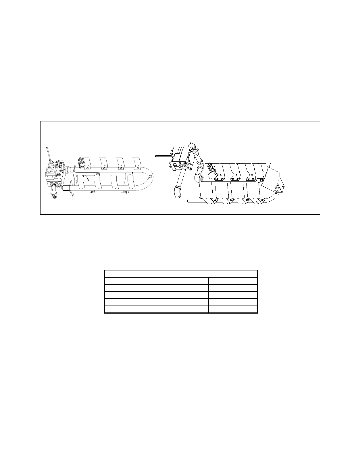
The flames originate from orifices in a U-shaped burner manifold positioned beneath the frypot.
The orifice diameters differ for natural and Propane (LP) gas and for fryers as indicated in the
accompanying table (NOTE: This table shows only the orifices used in elevations up to 1999
feet/609 meters. GF14 fryers have one orifice per deflector; GF40 fryers have two orifices per
deflector assembly.
GF14/GF40 Series Orifice Sizes (0-1999 ft/609 m)
Fryer & Gas Type Inches Millimeters
GF14 Natural 0.065 1.65mm
GF14 Propane (LP) 0.041 1.05mm
GF40 Natural 0.057 1.45mm
GF40 Propane (LP) 0.034 0.86mm
An electromechanical millivolt gas valve regulates gas flow to the burner manifold. GF14/GF40
fryers use a pilot ignition system to control burner firing.
Pilot Ignition System
The pilot ignition system is made up of the pilot orifice, pilot hood, and a thermopile. The pilot
serves two purposes: lighting the burner and heating the thermopile. In operation, the thermopile is
in contact with the pilot flame and generates millivolts. The millivolt output passes through a
normally closed high-limit switch and energizes the gas valve pilot coil, which in turn opens the
pilot valve. If the pilot flame is extinguished, voltage is lost to the gas valve pilot coil and the pilot
valve closes.
1-1
Page 6
Thermostats
1. These fryers are equipped with adjustable operating thermostats. The temperature at which the
thermostat opens and closes is adjusted by rotating a knob. The tolerance band of the Sunne
thermostat is +10°F (+6°C) and -20°F (-11°C ).
Fryers in the GF14/GF40 series are also equipped with a high-limit thermostat. In the event that the
fryer fails to properly control the oil temperature, the high-limit thermostat prevents the fryer from
overheating to the flash point. The high-limit thermostat acts as a normally closed power switch that
opens when exposed to temperatures above 425ºF to 450ºF (218ºC to 232ºC).
1.2 Accessing Fryers for Servicing
DANGER
Moving a fryer filled with cooking oil/shortening may cause spilling or splattering of
the hot liquid. Follow the draining instructions in Chapter 3 of the Installation and
Operation manual before attempting to relocate a fryer for servicing.
1. Drain all cooking oil/shortening from the fryer.
2. Shut off the gas supply to the unit and disconnect the unit from the gas supply.
3. Remove any attached restraining devices.
4. Relocate the fryer for service accessibility.
5. After servicing is complete, reconnect the unit to the gas supply and reattach the restraining
devices.
6. Refill the frypot with cooking oil/shortening.
1.3 Cleaning the Gas Valve Vent Tube
Refer to Quarterly Checks and Services in Chapter 4 of the Installation and Operation manual.
1.4 Checking the Burner Manifold Pressure
See step 7-15 in section 1.7.4, Replacing the Gas Valve.
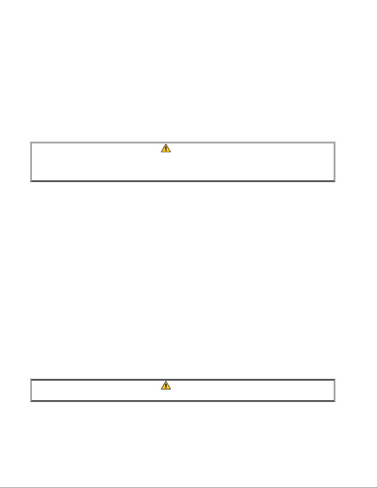
1.5 Adjusting Deflector Spacing and Alignment
DANGER
Drain the frypot or remove the handle from the drain valve before proceeding further.
Proper spacing of the edge of the deflectors is ¾-inch (19mm) from the frypot side. To adjust target
spacing, bend the brackets to which they are attached away or toward the frypot to the proper
distance. (A board of the proper thickness is useful as a gauge to verify spacing and alignment.)
The illustration below depicts a typical GF40. The GF14 procedure is the same except that there are
no ceramic targets.
1-2
Page 7
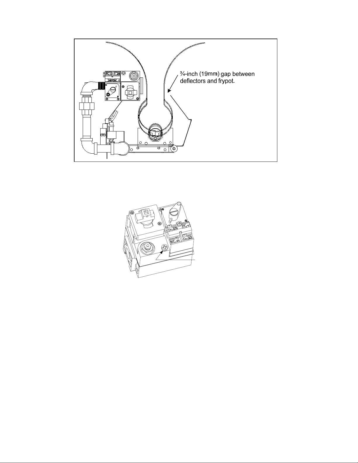
1.6 Adjusting the Pilot Flame
1. Remove the cap shown in the illustration below to access the pilot flame adjustment screw in the
gas valve.
Remove this cap to
access the pilot flame
adjustment screw.
2. Using a small, flat-tipped screwdriver, turn the pilot flame adjustment screw counterclockwise to
increase the length of the flame or clockwise to decrease the length of the flame. Adjust the
flame to a length of 1 to 1½ inches (25 to 38 mm).
3. Reinstall the pilot flame adjustment screw cap.
1.7 Replacing Fryer Components
1.7.1 Replacing the Operating Thermostat
1. Drain the fryer and turn the gas off.
2. Remove the thermostat knob by pulling straight out on the knob with a firm, steady pull.
3. Disconnect the wires from the thermostat.
4. Remove the two mounting screws to release the thermostat control from its mounting bracket.
1-3
Page 8
5. Straighten the clips that secure the thermostat bulb to the frypot. Use a slotted socket to unscrew
the thermostat from the frypot.
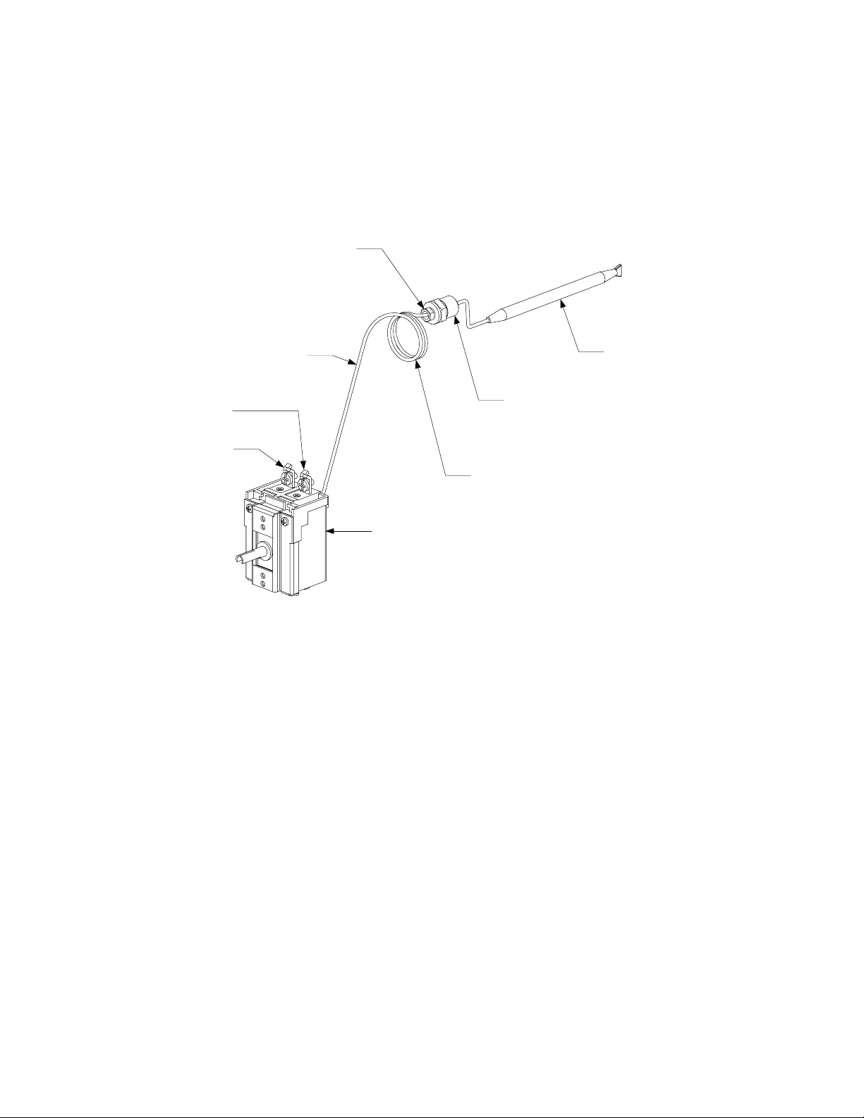
6. Loosen the capillary tube compression nut (the small nut) on the replacement thermostat so that
it slides freely on the capillary tube. Apply a small amount of Loctite™ PST56765 compound or
equivalent to the threads of the large fitting and screw the replacement thermostat securely into
the frypot, being careful not to twist the capillary tube as the fitting is tightened. DO NOT
tighten the capillary tube compression nut at this time.
Compression Nut
Thermostat Bulb
Attach wire 2C to
this terminal.
Attach wire 1C to
this terminal.
Capillary Tube
Large fitting screws
into frypot.
Carefully coil excess
capillary tube after securing
thermostat bulb to frypot and
tightening compression nut.
Thermostat Control
7. Position the thermostat bulb in the retaining clips and fold the clips down to secure it in place.
8. Gently form the capillary tube so that it lies close to the bottom surface and front wall of the
frypot, working any slack out through the fitting (see illustration above).
9. Tighten the capillary tube compression fitting and carefully coil the excess capillary tubing as
shown in the illustration above. Mount the thermostat control to the mounting bracket using the
screws removed in Step 4.
10. Connect the wires disconnected in Step 3 above to the thermostat as shown in the illustration on
Page 1-4.
11. Install the thermostat knob on the shaft of the thermostat control.
1.7.2 Replacing the High-Limit Thermostat
1. Drain the fryer and turn the gas off.
2. Disconnect the high-limit wires from the gas valve terminal block.
3. Use a slotted socket to unscrew the thermostat from the frypot.
1-4
Page 9

4. Ensure threads inside the fitting are clean and apply a small amount of Loctite™ PST56765
compound or equivalent to the threads of the new high-limit and screw it securely into the frypot.
5. Connect the wires to the gas valve terminals as shown in the illustration below (polarity does not
matter).
Attach hi-limit
wires to these
terminals.
Polarity does
not matter.
1.7.3 Replacing Deflectors
1. Drain the fryer and disconnect it from the gas supply.
2. Disconnect the wires from the gas valve terminal block, marking each wire to facilitate
reconnection.
3. Disconnect the pipe union collar at the right side of the gas valve.
4. On GF40 fryers, remove the burner heat shield hanger screws at the front of the burner and
remove the heat shield.
5. Remove the burner hanger screws and lower the front of the burner assembly. Pull it forward to
clear the rear burner hanger, then lower the burner to the floor of the cabinet. Carefully pull the
burner assembly from the cabinet.
6. GF14: Use a ½-inch box end wrench to remove the brass orifice that holds the deflector to the
burner manifold. Position the new deflector and reinstall the orifice.
GF40: Use a ½-inch box end wrench to remove the brass orifices that holds the deflector to the
burner manifold. Position the new deflector and reinstall the orifices.
WARNING
Use extreme care to prevent cross-threading and stripping when reinstalling the
brass orifices.
7. Reverse steps 1-5 to reinstall the burner assembly. Check spacing and alignment of targets in
accordance with Section 1.6.
1-5
Page 10

1.7.4 Replacing the Gas Valve
DANGER
Drain the frypot or remove the handle from the drain valve before proceeding further.
1. Disconnect fryer from the gas supply.
2. Disconnect the wiring from the gas valve terminal block, marking each wire to facilitate
reconnection.
3. Disconnect the pilot gas line fitting from the gas valve and remove the vent tube.
4. GF14: Disconnect the pipe union to the right of the gas valve and rotate the valve assembly
outward just enough to allow the valve to be unscrewed from the burner manifold piping.
GF40: Disconnect the pipe unions at each side of the gas valve and remove the valve from the
assembly.
5. Remove the fittings from the old gas valve and install them on the replacement valve, using
Loctite™ PST56765 or equivalent pipe thread sealant on threads. Install the vent tube removed
from the old valve. DO NOT use thread sealant on the vent tube.
6. Reverse steps 1-4 to install the replacement valve, reconnecting the wiring in accordance with
the wiring diagram on the door of the fryer or with the notes made in Step 2. Return the fryer to
operation and check the burner manifold pressure, as detailed below.
7. Ensure that the gas valve knob is in the OFF position.
8. Remove the pressure tap plug from burner manifold.
9. Insert the fitting for a manometer or pressure gauge into the pressure tap hole.
10. Place the gas valve in the PILOT position and light the pilot. When the pilot lights and
continues to burn, increase the setting on the thermostat knob until the burner lights. Compare
the manometer or gauge reading to the appropriate table below.
GF14 Standard
for Burner Manifold Pressure
Gas Type Pressure
Natural
LP
(1.00 kPa or 9.96 mbar)
(2.49 kPa or 24.91 mbar)
4.0” WC
10.0” W.C
for Burner Manifold Pressure
Gas Type Pressure
Natural
LP
GF40 Standard
3.5” WC
(0.87 kPa or 8.72 mbar)
8.25” W.C.
(2.06 kPa or 20.55 mbar)
11. If the burner manifold pressure does not meet the specifications in the tables in Step 4, unscrew
the slotted cap from the top of the gas valve regulator (adjacent to the gas valve vent tube) and
turn the adjusting screw to obtain the correct pressure. Turn the screw clockwise to increase
pressure, counter-clockwise to decrease pressure.
12. After adjusting the manifold pressure to the correct value, reinstall the regulator cap and turn the
gas valve knob to the OFF position.
1-6
Page 11

13. Remove the manometer or pressure gauge fitting from the pressure tap hole and reinstall the pipe
plug.
14. Place the gas valve in the PILOT position and check for gas leaks. If no leaks are found, re-light
the pilot and return the unit to operation.
1.7.5 Replacing the Thermopile or Pilot Assembly
DANGER
Drain the frypot or remove the handle from the drain valve before proceeding further.
A pair of small screws (see illustration below) attaches the pilot assembly, which consists of the
pilot and the thermopile, to the burner manifold.
Mounting screws pass through
this bracket from the rear.
Mounting Screws
On GF14 units, the pilot and thermopile assembly can
be removed by disconnecting the pilot tube and
removing the two screws that hold it in place.
On GF40 units, the pilot and thermopile assembly is
attached to its mounting bracket by two screws that pass
through the bracket from the rear. The burner assembly
should be removed to access these screws.
1. To replace only the thermopile, disconnect the leads from the gas valve, remove the guard, bend
the clip at the bottom of the pilot assembly outward, and press the thermopile out of the
assembly from the top. Reverse the procedure to install the replacement thermopile.
1-7
Page 12

3: Press down on t op o f thermopile,
forcing it out of the pilot bracket.
1: Remove these screws
to release guard.
2: Bend this clip outward to
release thermopile.
3. To replace the complete pilot assembly:
a. Disconnect the pilot tube from the bottom of the pilot assembly.
b. GF14: Remove the screws from the pilot-mounting bracket to release the pilot assembly.
GF40: Remove the burner manifold assembly in accordance with Steps 1-5 of Section 1.8.3.
c. Disconnect the thermopile lead from the gas valve pilot coil.
d. Reverse steps a through c to install the replacement pilot assembly.
4. Reinstall the burner assembly by reversing steps 1-5 of Section 1.8.3.
5. Verify that the pilot flame is 1 to 1½-inches long. If not, adjust the pilot flame length in
accordance with Section 1.7.
1.7.6 Replacing the Frypot
1. Drain the frypot and disconnect the fryer from the gas supply.
2. Remove all accessories (e.g., frypot covers, drop-in probes, basket hangers, etc.).
3. Remove the screws from the sides and back of the flue cap and lift it off the fryer.
4. Remove the screws from the front cowling (front panel) and pull the bottom edge forward
enough to disengage the upper door hinge pin from the hole in the bottom of the cowling. Catch
the door with one hand to prevent it from falling when the hinge pin disengages.
5. Remove the door by lifting it upward to disengage the lower hinge pin from the hinge bracket,
being careful not to lose the three Teflon spacers located between the lower edge of the door and
the hinge bracket.
6. Remove the cowling by pulling its bottom edge outward slightly and slipping the upper edge
downward from under the front lip of the frypot.
1-8
Page 13

7. Remove the screw from the frypot hold-down bracket located at the center of the cabinet cross
brace.
8. Dismount the thermostat control from the thermostat bracket.
9. Disconnect the pipe union on the right side of the gas valve.
10. Lift the frypot assembly upward from the cabinet.
11. Recover the drain valve, high-limit thermostat, operating thermostat, and burner manifold
assembly from the failed frypot.
12. Clean the threads on the recovered parts, apply Loctite™ PST 56765 or equivalent thread sealer,
and install them on the replacement frypot.
13. Reverse Steps 1-10 to install the replacement frypot in the cabinet.
1.8 Troubleshooting and Problem Isolation
This section is intended to provide technicians with a general knowledge of the broad problem
categories associated with this equipment, and the probable causes of each. With this knowledge, the
technician should be able to isolate and correct any problem encountered.
Problems you are likely to encounter can be grouped into these broad categories:
1. Pilot failures
2. Improper burner functioning
3. Improper temperature control
4. Leaking
The probable causes and corrective actions for each category are discussed in the following sections.
1.8.1 Pilot Failures
Pilot failures fall into one or the other of two categories – failure to light or failure to remain lit.
Pilot Fails to Light
1. Gas is not being supplied to the valve: Check for a closed gas cutoff valve upstream of the gas
valve. Also verify that the gas line quick disconnect fitting at the rear of the fryer (if so
equipped) is properly connected.
2. Blocked pilot orifice: If gas is reaching the valve but the pilot will not light, check for an
obstruction in the pilot orifice, especially in new installations. If the orifice is clear, check to be
sure that the pilot adjustment screw is not completely closed.
1-9
Page 14

Pilot Does Not Remain Lit When Gas Valve Knob is Released
The electromechanical Honeywell gas valve used on the GF14 and GF40 fryers has a pair of
normally open coils (electromagnetic switches) that close when low voltage is applied to them. If
the coils do not close, the valve will not open to supply gas to the pilot or to the burner manifold.
Turning the gas valve knob to the pilot position and pressing it in bypasses the pilot coil, allowing
the pilot to be lighted. The pilot flame heats the thermopile, which generates the voltage required to
close the coils. If the pilot flame goes out when the knob is released, there are four probable causes:
1. Open or grounded high-limit: The high-limit thermostat functions as a normally closed
switch. If the high-limit is open or grounded, the gas valve coil will not pull in and no gas will be
supplied to the pilot or to the burner manifold.
Check and Corrective Action: Detach the high-limit leads from the gas valve and check for
continuity. If the high-limit fails the continuity check, it must be replaced.
2. Loose/corroded wiring connections on high-limit or thermopile: This has the same effect as
an open or grounded high-limit. If the gas valve coils do not receive the appropriate voltage
from the thermopile, they will not close and no gas will be supplied to the pilot or to the burner
manifold.
Check and Corrective Action: Check wiring connections for corrosion and tightness. Check
terminals to verify that they are securely attached to their leads.
3. Low or no voltage out of thermopile: If the tip of the thermopile is not surrounded by the pilot
flame, it will not generate sufficient voltage to the gas valve coils for them to close. No gas will
be supplied to the pilot or to the burner manifold.
Checks and Corrective Actions:
Observe pilot flame through the viewing port in the lower left corner of the frypot front baffle
assembly. If the pilot flame is less than 1-inch (25mm) adjust the pilot flame in accordance with
Section 1.7. If the flame is being blown away from the pilot, eliminate the draft that is causing it
to be blown away from the thermopile.
If the pilot flame correctly impinges the tip of the thermopile, connect a multimeter in series with
either of the thermopile leads and its gas valve terminal. Light the pilot and allow it to burn for
at least two minutes, then check the voltage output. If voltage is less than 400 millivolts, replace
the thermopile.
4. Malfunctioning gas valve: If either of the coils in the gas valve fails, no gas will be supplied to
the pilot or to the burner manifold.
Check and Corrective Action: If all the above checks are satisfactory, the gas valve has failed.
Replace the gas valve.
1-10
Page 15

1.8.2 Improper Burner Functioning
If the burner lights on one side only, the probable causes are a missing or misaligned rear deflector
or improper burner manifold pressure. Clogged burner orifices are usually the cause of gaps in
burner firing.
Fluctuating flame intensity is normally caused by improper or fluctuating incoming gas pressure,
but may also be the result of variations in the kitchen atmosphere. Variation in the kitchen
atmosphere is usually caused by air conditioning and/or ventilation units starting and stopping. As
the units start and stop, the pressure in the kitchen may change. Changes in airflow patterns can also
affect flame intensity. If the incoming gas pressure is correct and stable, check for variations in the
kitchen atmosphere.
Flames “rolling” out of the fryer are usually an indication of negative pressure in the kitchen. Air
is being sucked out of the fryer enclosure and the flames are literally following the air. If negative
pressure is not the cause, check for high burner manifold gas pressure. An obstructed flue, which
prevents the fryer from properly exhausting, may also be the cause.
An excessively noisy burner, especially with flames visible above the flue opening, may indicate
that the burner gas pressure is too high, or it may simply be that the gas valve vent tube is blocked.
If the gas pressure is correct and the vent tube in unobstructed, the gas valve regulator is probably
defective.
Occasionally a burner may apparently be operating correctly, but nevertheless the fryer has a slow
recovery rate (the length of time required for the fryer to increase the oil temperature from 250ºF to
300ºF (121ºC to 149ºC). The primary causes of this are low burner manifold pressure and/or
misaligned or missing deflector targets. If both of these causes are ruled out, the probable cause is a
gas valve regulator that is out of adjustment. Refer to the Check Burner Manifold Pressure
procedure in the Semi-Annual Checks and Services section of Chapter 4 of the Installation and
Operation manual.
1.8.3 Improper Temperature Control (i.e., failure to control at set point)
Temperature control is a function of several interrelated components, each of which must operate
correctly. The principle component, however, is the thermostat.
The thermostat must be checked periodically.
Causes of temperature problems may be damage to the thermostat bulb, kinking of the capillary
tube, and broken or loose wiring. Inspect the thermostat components for visible damage.
If there are dents in the bulb, if the capillary is kinked, or if there is obvious damage to the leads, the
thermostat should be replaced.
If there is no obvious damage to the thermostat, turn off the gas valve and allow the cooking
oil/shortening to cool to at least 15 degrees below the thermostat setting. Disconnect the thermostat
leads from the gas valve and check for continuity. If the thermostat fails the continuity check, it
must be replaced.
1-11
Page 16

1.8.4 Leaking
Leakage of the frypot almost always will be due to improperly sealed high-limits, thermostats, or
drain fittings. When installed or replaced, each of these components must be sealed with Loctite™
PST56765 sealant or equivalent to prevent leakage. In very rare cases, a leak may develop along
one of the welded edges of the frypot. When this occurs, the frypot must be replaced.
If the sides and/or ends of the frypot are coated with oil/shortening, the most likely cause is spillage
over the top of the frypot rather than leakage.
1.9 Wiring Diagram
1.9.1 Current Production Units with Honeywell Gas Valve
High-Limit Therm ostat
Thermopile
1C
2C
Operating Thermostat
1-12
Page 17

GF14/GF40 SERIES GAS FRYERS
CHAPTER 2: GF14/GF40 PARTS LIST
ACCESSORIES
1
1/1/08 and Later
5
3
8
6
7
9
2
Item Part # Component
1 803-0015 Basket, Full
2 803-0032 Rack, basket support, GF14
* 803-0132 Rack, basket support, GF40
* 803-0037 Basket rack, fine mesh GF14
* 803-0136 Basket rack, fine mesh GF40
3 803-0197 Cleanout Rod, 27-Inch
4 803-0271 Basket, Twin
5 806-5518 Cover, Frypot
6 Quick-Disconnect Fitting, Female
810-0070 ¾-inch
810-0073 1-inch
7 Quick-Disconnect Fitting, Male
810-0072 ¾-inch
810-0074 1-inch
8 Hose, Flexible Gas
810-0083 ¾-inch x 36-inch
810-0084 ¾-inch x 48-inch
810-0088 1-inch x 36-inch
810-0085 1-inch x 48-inch
9 826-1095 Anchor Strap Kit (for use only on fryers equipped with legs)
* 826-0900 Chain Restraint Kit (for use only on fryers equipped with casters)
* 812-1226SP Drain Extension
* 810-3169 Leg, pack of 4
* 810-0750 Caster, 90° rigid
* 810-0356 Caster, without brake
* 810-0357 Caster, with brake
* 106-4386SP Toggle switch
* 810-2793 Basket hanger
4
2-1
Page 18

Item Part # Component
* 809-0171 Basket hanger screw (spacer 809-0921)
* 803-0188 Sediment tray, GF14
* 803-0103 Sediment tray, GF40
Burners
Item Part # Component
1 200-0176 Bracket, Front Manifold Mounting
2 200-0177 Hanger, Rear Manifold
* 200-0749 Guard, Thermopile
3 Valve, Honeywell Millivolt Gas
807-1603
807-1604
* 810-0975 Knob
4 810-0691 Tube, Gas Valve Vent
* 810-0703 Gas Line, .25-inch x 17.50-inch
5 810-1862 Manifold, Burner , GF14
* 826-1139 GF14 Conversion Kit, Natural to LP
Natural (See NOTE 2.)
Propane (See NOTE 2.)
Conversion Kits
2-2
Page 19

p
Item Part # Com
* 826-1140 GF14 Conversion Kit, LP to Natural
* 826-1143 GF40 Conversion Kit, Natural to LP
* 826-1144 GF40 Conversion Kit, LP to Natural
6 Pilot Assembly (Includes bracket, hood, and thermopile.
810-2071 Natural Gas w/.024-inch Orifice 810-0149
810-2070 Propane Gas w/.013-inch Orifice 810-0148
7 900-1032 Bracket, Pilot Mounting
8 910-1082 Deflector, GF14
9 230-1177 Deflector, GF40
10 823-0496 Deflector, rear, GF40
* 910-2113 Deflector, rear, GF14
11 230-1206 Burner, manifold, GF40
NOTE 1: For gas valve knob only, use P/N 8 10-0975. NOTE 2: Use kit 826-1139 to convert valve from natural gas to
Propane; use kit 826-1140 to convert from Propan e to natural gas. Kits also include appropriate pilot orifices. NOTE 3:
For Pilot only, order P/Ns 810-0426 (Natural) or 810-0427 (Propane). For Thermopile only, order P/N 810-0159.
onent
Standard Orifices
GF14, Natural
GF 14, Propane
GF40, Natural
GF40, Propane
Part #
826-1388 1.655mm 0-1999 feet (0-609 meters) 10
826-1354 1.05 mm 0-1999 feet (0-609 meters) 10
826-1357 1.45 mm 0-1999 feet (0-609 meters) 10
826-1387 0.86mm 0-1999 feet (0-609 meters)
Size Altitude Qty
10
High-Altitude Orifices
GF14, Natural Gas
Part #
810-2804 1.60 mm 2000-3999 (610-1219 meters)
812-0907 1.55 mm 4000-5999 feet (1220-1829 meters)
812-1204 1.50 mm 6000-7999 feet (1830-2438 meters)
826-1357 1.45 mm 8000-8999 feet (2439-2743 meters)
826-1386 11.40 mm 9000-9999 feet (2744-3048 meters)
Size Altitude
Qty
10
10
1
1
1
GF 14, Propane
GF40, Natural
GF40, Propane
810-0135 1.02 mm 2000-3999 (610-1219 meters)
826-1391 0.99 mm 4000-59 99 feet (1220-1829 meters)
812-0906 0.95 mm 6000-79 99 feet (1830-2438 meters)
812-0915 0.93 mm 8000-89 99 feet (2439-2743 meters)
812-0910 0.90 mm 9000-99 99 feet (2743-3048 meters)
826-1386 1.40 mm 2000-3999 feet (610-1219 meters)
810-0361 1.36 mm 4000-5999 feet ( (1220-1829 meters)
810-0131 1.30 mm 6000-79 99 feet (1830-2438 meters)
810-0951 1.25 mm 8000-8999 feet (2439-2743 meters)
810-0323 1.20 mm 9000-99 99 feet (2744-3048 meters)
810-0952 0.82 mm 2000-3999 (610-1219 meters) 1
826-1352 0.81 mm 4000-5999 feet (1220-1829 meters) 10
812-0914 0.78 mm 6000-7999 feet (1830-2438 meters) 1
812-1302 0.76 mm 8000-8999 feet (2439-2743 meters) 1
812-0444 10.74 mm 9000-9999 feet (2743-3048 meters) 1
1
10
1
1
1
10
1
1
1
1
2-3
Page 20

Cabinetry
Item Part # Component
1 200-6903 Back
2 816-0656 Insulation, back
Sides
3 201-6917 Side, left, stainless
4 202-6917 Side, right, stainless
* 212-6893 Right, painted
* 211-6893 Left, painted
5 230-4685 Hinge, lower
6 900-4813 Brace, cabinet top
7 106-9539 Door assembly
* 230-4960 Handle, universal
8 106-4067 Pin assembly
9 824-1914 Control panel
* 810-1105 Magnet, offset door
2-4
Page 21

Frypots
Item Part # GF14 Frypot Components
1 823-1024 Flue assembly
2 823-6655 Frypot
* 823-4493 Sysco-branded fryers
806-7972 Operating thermostat (Sysco fryer)
3 106-0770 Thermostat
* 826-1177 Hi-limit
* 807-1692 Operating thermostat
* 910-2113 Target, rear, GF14
* 810-1569 Valve, 1.25-inch Drain
* 910-3557 Deflector, flue
* 826-0861 Insulation kit
* Not Illustrated
2-5
Page 22

Item Part # GF40 Frypot Components
1 806-5567 Flue
2 823-6667 Frypot
3 826-1177 Hi-limit thermostat
* 807-1692 Operating thermostat
* 810-1569 Valve, 1.25-inch Drain
* 910-3557 Deflector, flue
* 826-0861 Insulation kit
2-6
Page 23

THIS PAGE INTENTIONALLY LEFT BLANK
Page 24

Frymaster, L.L.C., 8700 Line Avenue, Shreveport, Louisiana 71106
TEL 1-318-865-1711 FAX (Parts) 1-318-219-7140 FAX (Tech Support) 1-318-219-7135
PRINTED IN THE UNITED STATES
SERVICE HOTLINE
1-800-551-8633
819-6438
APRIL 2009
 Loading...