

Frymaster GASFRYERSMODELS 35, GASFRYERSMODELS 45, Performance Pro 35, Performance Pro 45 User Manual
Page 1
Gas Fryers Models 35 & 45
Performance Pro Series
Service and Parts Manual
Frymaster, a member of the Commercial Food Equipment Service Association, recommends
using CFESA Certied Technicians.
24-Hour Service Hotline 1-800-551-8633
APRIL 2006
Page 2
IF, DURING THE WARRANTY PERIOD, THE CUSTOMER USES A PART FOR THE ENODIS
EQUIPMENT OTHER THAN AN UNMODIFIED NEW OR RECYCLED PART PURCHASED DIRECTLY
FROM FRYMASTER AND DEAN, OR ANY OF ITS AUTHORIZED SERVICE CENTERS, AND/OR
THE PART BEING USED IS MODIFIED FROM ITS ORIGINAL CONFIGURATION, THIS WARRANTY
WILL BE VOID. FURTHER, FRYMASTER AND DEAN AND ITS AFFILIATES WILL NOT BE LIABLE
FOR ANY CLAIMS, DAMAGES OR EXPENSES INCURRED BY THE CUSTOMER WHICH ARISE
DIRECTLY OR INDIRECTLY, IN WHOLE OR IN PART, DUE TO THE INSTALLATION OF ANY
MODIFIED PART AND/OR PART RECEIVED FROM AN UNAUTHORIZED SERVICE CENTER.
NOTICE
This appliance is intended for professional use only and is to be operated by qualied personnel only.
A Frymaster/DEAN Factory Authorized Service Center (FASC) or other qualied professional should
perform installation, maintenance, and repairs. Installation, maintenance, or repairs by unqualied
personnel may void the manufacturer’s warranty.
NOTICE
This equipment must be installed in accordance with the appropriate national and local codes of the
country and/or region in which the appliance is installed.
NOTICE TO U.S. CUSTOMERS
This equipment is to be installed in compliance with the basic plumbing code of the Building Ofcials
and Code Administrators International, Inc. (BOCA) and the Food Service Sanitation Manual of the
U.S. Food and Drug Administration.
NOTICE
Drawings and photos used in this manual are intended to illustrate operational, cleaning and technical
procedures and may not conform to onsite management operational procedures.
NOTICE TO OWNERS OF UNITS EQUIPPED WITH COMPUTERS
U.S.
This device complies with Part 15 of the FCC rules. Operation is subject to the following two conditions:
1) This device may not cause harmful interference, and 2) This device must accept any interference
received, including interference that may cause undesired operation. While this device is a veried
Class A device, it has been shown to meet the Class B limits.
CANADA
This digital apparatus does not exceed the Class A or B limits for radio noise emissions as set out by
the ICES-003 standard of the Canadian Department of Communications.
Cet appareil numerique n’emet pas de bruits radioelectriques depassany les limites de classe A et B
prescrites dans la norme NMB-003 edictee par le Ministre des Communcations du Canada.
DANGER
Improper installation, adjustment, maintenance or service, and unauthorized alterations or modications
can cause property damage, injury, or death. Read the installation, operating, and service instructions
thoroughly before installing or servicing this equipment. Only qualied service personnel may convert
this appliance to use a gas other than that for which it was originally congured.
Page 3
DANGER
Adequate means must be provided to limit the movement of this appliance without depending upon the
gas line connection. Single fryers equipped with legs must be stabilized by installing anchor straps. All
fryers equipped with casters must be stabilized by installing restraining chains. If a exible gas line is
used, an additional restraining cable must be connected at all times when the fryer is in use.
DANGER
The front ledge of the fryer is not a step! Do not stand on the fryer. Serious injury can result from slips
or contact with the hot oil.
DANGER
Do not store or use gasoline or other ammable liquids or vapors in the vicinity of this or any other appliance.
DANGER
Instructions to be followed in the event the operator smells gas or otherwise detects a gas leak must
be posted in a prominent location. This information can be obtained from the local gas company or
gas supplier.
DANGER
The crumb tray in fryers equipped with a lter system must be emptied into a reproof container at the
end of frying operations each day. Some food particles can spontaneously combust if left soaking in
certain shortening material.
WARNING
Do not bang fry baskets or other utensils on the fryer’s joiner strip. The strip is present to seal the joint
between the fry vessels. Banging fry baskets on the strip to dislodge shortening will distort the strip,
adversely affecting its t. It is designed for a tight t and should only be removed for cleaning.
Page 4

PERFORMANCE PRO SERIES GAS FRYERS MODELS 35 & 45
Table of Contents
CHAPTER 1: Service Procedures
1.1 General .................................................................................................................................................1-1
1.1.1 Pilot Ignition ..............................................................................................................................1-1
1.1.2 Electronic Ignition .....................................................................................................................1-1
1.1.3 Controller Options .....................................................................................................................1-2
1.1.4 Thermostats and Temperature Probes ........................................................................................1-2
1.2 Moving the Fryer for Servicing ...........................................................................................................1-2
1.3 Diagnostic Procedures .........................................................................................................................1-3
1.3.1 Cleaning the Gas Valve Vent Tube ............................................................................................1-3
1.3.2 Checking the Burner Manifold Gas Pressure ............................................................................1-3
1.3.3 Adjusting the Pilot Flame ..........................................................................................................1-5
1.3.4 Adjusting Burner Ceramic Target Spacing and Alignment .......................................................1-5
1.3.5 Calibrating the Thermostat ........................................................................................................1-5
1.3.6 Testing the Temperature Prode ..................................................................................................1-7
1.4 Replacing Fryer Components ..............................................................................................................1-7
1.4.1 Replacing a Controller or Computer .........................................................................................1-7
1.4.2 Replacing the Operating Thermostat in Units with Thermostat Control Panels .......................1-8
1.4.3 Replacing the Operating Thermostat in Units with Thermostat Access Doors .........................1-8
1.4.4 Replacing the Temperature Probe ..............................................................................................1-9
1.4.5 Replacing the High-Limit Thermostat in Fryers with Thermostat Controls .............................1-9
1.4.6 Replacing the High-Limit Thermostat in Fryers with Other Controls ......................................1-9
1.4.7 Replacing the Heat Mode Indicator Light in Fryers with Thermostat Controls ......................1-10
1.4.8 Replacing the Power or Melt Cycle Switch in Fryers with Thermostat Controls ...................1-10
1.4.9 Replacing Burner Ceramic Targets ..........................................................................................1-11
1.4.10 Replacing the Gas Valve ........................................................................................................ 1-11
1.4.11 Replacing the Pilot Assembly or Thermopile ........................................................................1-12
1.4.12 Replacing the Frypot .............................................................................................................1-12
1.5 Troubleshooting and Problem Isolation .............................................................................................1-14
1.5.1 Typical Problems .....................................................................................................................1-14
Pilot Failure .............................................................................................................................1-14
Ignition Failure ........................................................................................................................1-14
Improper Burner Function .......................................................................................................1-15
Improper Temperature Control ................................................................................................1-17
Gas Valve Malfunction ............................................................................................................1-17
Computer Malfunction ............................................................................................................1-17
Filtration Malfunction..............................................................................................................1-19
Leakage ....................................................................................................................................1-20
Basket Lift Malfunction...........................................................................................................1-20
1.5.2 Interpretation of Analog Controller Lights ..............................................................................1-23
1.6 Probe Resistance Chart ......................................................................................................................1-23
1.7 Troubleshooting Guides .....................................................................................................................1-24
1.7.1 Troubleshooting the 24 VAC Circuit: Analog Controller ........................................................1-24
Troubleshooting the 24 VAC Circuit: Electronic Ignition (Computer Controller) ..................1-24
Troubleshooting the 24 VAC Circuit: Standing Pilot (Computer Controller) .........................1-25
1.7.2 Troubleshooting the Gas Valve ................................................................................................1-25
1.7.3 Troubleshooting the Thermostat ..............................................................................................1-25
1.7.4 Troubleshooting the Temperature Probe ..................................................................................1-26
1.8 Wiring Diagrams ................................................................................................................................1-27
1.8.1 Standing Pilot ..........................................................................................................................1-27
1.8.2 Electronic Ignition ...................................................................................................................1-28
1.8.3 Non-Computer Controlled .......................................................................................................1-29
1.8.4 Filter Box .................................................................................................................................1-30
1.8.5 Modular Basket Lift 100/120V ................................................................................................1-31
1.8.6 Modular Basket Lift 208/250V ................................................................................................1-32
Page 5

PERFORMANCE PRO SERIES GAS FRYERS MODELS 35 & 45
Table of Contents
CHAPTER 2: Parts List
2.1 Accessories ..........................................................................................................................................2-1
2.2 Basket Lift and Associated Parts ..........................................................................................................2-2
2.3 Cabinetry ..............................................................................................................................................2-4
2.3.1 FPP/FMP Model Cabinetry .......................................................................................................2-4
2.3.2 PMJ (Non-lter) Model Cabinetry ............................................................................................2-6
2.4 Casters, Legs, and Associated Hardware .............................................................................................2-9
2.5 Component Boxes ..............................................................................................................................2-10
2.5.1 Component Boxes without Melt Cycle ...................................................................................2-10
2.5.2 Component Boxes with Melt Cycle .........................................................................................2-12
2.5.3 Component Boxes with Standing Pilot ....................................................................................2-14
2.5.4 Component Boxes with Electronic Ignition ............................................................................2-16
2.6 Control Panel Assemblies, Flue Caps, and Related Items .................................................................2-18
2.7 Controller Assemblies ........................................................................................................................2-20
2.8 Door Assembly...................................................................................................................................2-22
2.9 Drain System Components ................................................................................................................2-23
2.9.1 Drain Tube System ..................................................................................................................2-23
2.9.2 Drain Valves; FPP/FMP Models ..............................................................................................2-24
2.9.3 Drain Valves; PMJ Models ......................................................................................................2-26
2.10 Filter Boxes ......................................................................................................................................2-27
2.11 Filter Pan Assembly .........................................................................................................................2-29
2.12 Frypots .............................................................................................................................................2-30
2.13 Frypot Cabinetry ..............................................................................................................................2-31
2.13.1 MJ45 Frypot Cabinetry ..........................................................................................................2-31
2.13.2 MJ35 Frypot Cabinetry ..........................................................................................................2-32
2.14 Gas Valves and Burners ...................................................................................................................2-33
2.14.1 MJ45 Gas Valves and Burners ...............................................................................................2-33
2.14.2 MJ35 Gas Valves and Burners ...............................................................................................2-35
2.15 Oil Return Components ...................................................................................................................2-37
2.16 Power Shower ..................................................................................................................................2-39
2.17 Thermostats and Timers ...................................................................................................................2-40
2.18 Wiring Harnesses, Pin Terminals, and Power Cords .......................................................................2-41
2.19 Garland Range (S35) Parts ...............................................................................................................2-42
Page 6

PERFORMANCE PRO SERIES GAS FRYERS MODELS 35 & 45
CHAPTER 1: SERVICE PROCEDURES
1.1 General
Performance Pro Series gas fryers (formerly Master Jet 35- and 45-series fryers) contain a welded
stainless steel frypot directly heated by gas ames diffused evenly over its lower surface by ceramic
targets. The ames originate from orices in a U-shaped burner manifold positioned beneath the frypot.
They are equipped with either a millivolt gas valve or electromechanical gas valve that regulates gas ow
to the manifold. For operating information, refer to the Performance Pro Series Gas Fryers Models 35 &
45 Installation and Operation manual (P/N 819-6042). (Furthermore, referred to as the Installation and
Operation manual.)
1.1.1 Pilot Ignition
The pilot system is the pilot orice, pilot hood, and thermopile. The pilot serves two purposes: lighting
the burners and heating the thermopile. In operation, the thermopile is in contact with the pilot ame
and generates millivolts. The millivolt output passes through a normally closed high-limit switch and
energizes the gas valve pilot coil, which opens the pilot valve. If the pilot ame is extinguished, the gas
valve pilot coil loses voltage and the pilot valve closes.
In units equipped with 24-volt electromechanical gas valves, a separate 24-volt circuit activated by the
fryer power switch provides voltage through the thermostat or controller to the gas valve main coil,
which opens the main valve. The main gas valve will not open if the pilot valve is not open. Light the
pilot ame manually using a match or the optional built-in piezo ignitor after installing the fryer.
1.1.2 Electronic Ignition
In units congured for electronic ignition, an ignition module connected to an ignitor assembly replaces
the pilot system. The ignition module performs three important functions: supply voltage to the gas
valve, provide an ignition spark, and proof the pilot ame. The module contains a 4-second time delay
circuit and a coil that activates the gas valve. The ignitor assembly consists of a spark plug, a pilot, and
a ame sensor element.
At start-up the power switch is placed in the ON position, supplying 12 VDC to the heat control circuitry
in the controller or computer and to one side of the heat relay coil on the interface board. If resistance in
the temperature probe indicates the temperature in the frypot is below 180°F (82°C), the current ows
through a melt cycle circuit where a timer switch alternately closes for 3 seconds and opens for 24
seconds. If the temperature is 180°F (82°C) or above, the current ows through a heat circuit, bypassing
the timer switch. In either case, current is supplied to the other leg of the heat relay coil, which closes an
electronic switch in the 24 VAC circuit to provide current to the ignition module.
Circuitry in the ignition module sends 24 VAC current to the gas valve via a normally closed high-limit
switch and a drain safety switch. Simultaneously, the module causes the ignitor to spark for 4 seconds
to light the pilot ame. A ame sensor veries that the pilot is lit by measuring the ow of microamps
through the ame. If the pilot does not light or is extinguished, current to the ignition module is stopped,
preventing the main valve from opening, and the ignition module locks out until the power switch is
turned OFF, then back ON.
1-1
Page 7

1.1.3 Controller Options
Performance Pro gas fryers may be equipped with thermostat controls, analog controllers, digital
controllers, basket lift timers, or Computer Magic computers. In fryers equipped with thermostat control
panels, the fryer and melt cycle are turned on and off using rocker switches and the temperature is set by
a knob connected directly to the frypot-mounted thermostat. These units have no interface board. When
the melt cycle switch is placed in the ON position, the fryer stays in the melt cycle mode until the switch
is manually placed in the OFF position, even if the oil is at setpoint temperature. In units equipped with
thermostat access doors, the temperature control knob is located behind the hinged front panel. Service
procedures for this type of thermostat are slightly different from units with other thermostat controls.
Fryers equipped with other types of controllers have an interface board located in the component shield
behind the control panel.
1.1.4 Thermostats and Temperature Probes
Performance Pro gas fryers may have different kinds of thermostats depending on their conguration.
Fryers equipped with thermostat controls have an adjustable controlling thermostat. Adjust the temperature
at which the thermostat opens and closes by turning the attached knob. The Fenwal controlling thermostat
used in these fryers is sensitive to 1° changes in temperature.
Fryers equipped with other types of controls have a temperature probe. In these units, the probe resistance
varies directly with the temperature. As the temperature rises, so does the amount of resistance at a rate
of approximately 2 ohms for every 1° (F or C) of temperature (see Probe Resistance Chart, Section 1.6).
Circuitry in the controller monitors the probe resistance and controls burner ring when the resistance
exceeds or falls below programmed temperatures (i.e., setpoint). To program temperatures into the fryer,
use the keypad on the face of the controller. When testing temperature probes, unplug the 15-pin wiring
harness from the controller; otherwise, the reading may be incorrect due to extra resistance.
All open burner fryers are equipped with a high-limit thermostat. If the fryer fails to properly control oil
temperature, the high-limit thermostat prevents the fryer from overheating to ash point. The high-limit
thermostat acts as a normally closed power switch that opens when exposed to temperatures between
425°F to 450°F (218°C to 232°C). It will automatically reset when the oil temperature drops below
350°F (177°C).
1.2 Moving the Fryer for Servicing
If it is necessary to move the fryer before servicing, complete the following actions:
1. Drain the frypot.
2. Turn off the gas supply to the unit. Unplug any power cords. Disconnect the unit from the gas
supply.
3. Remove attached restraining devices, including chain restraints and anchor straps.
4. Relocate the fryer to an appropriate area for servicing.
1-2
Page 8
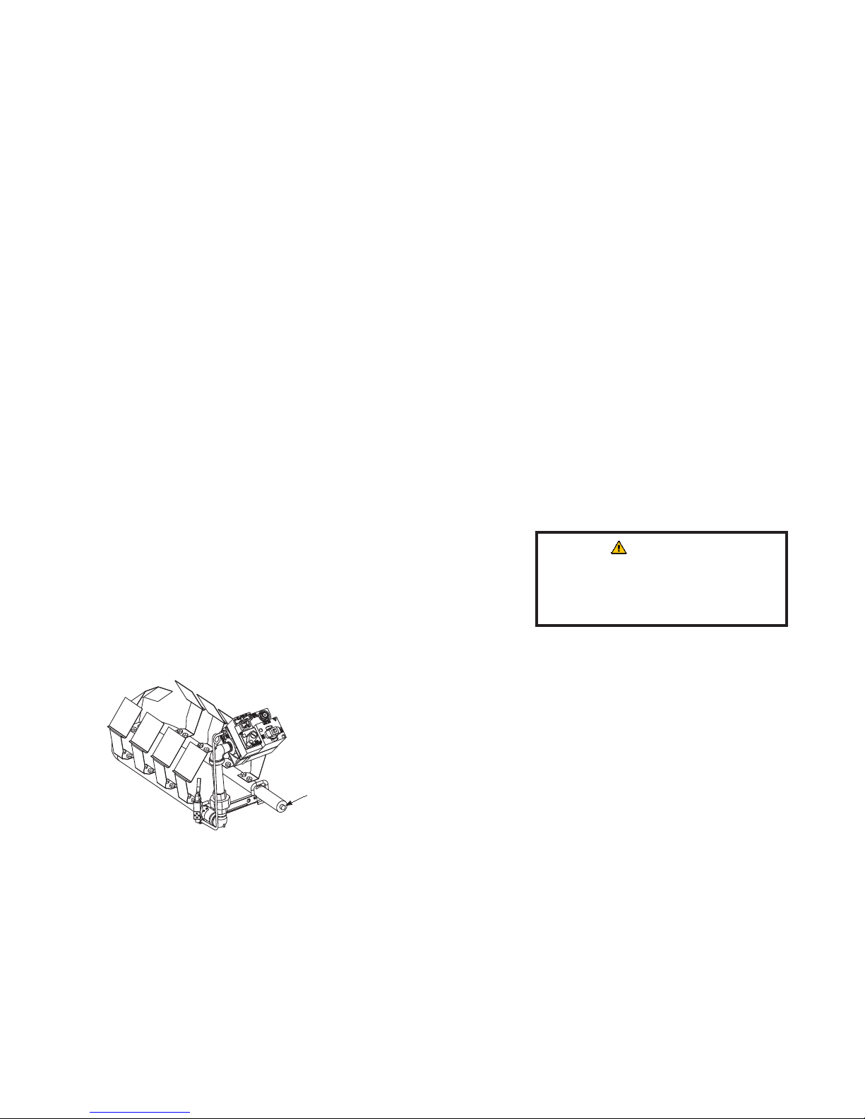
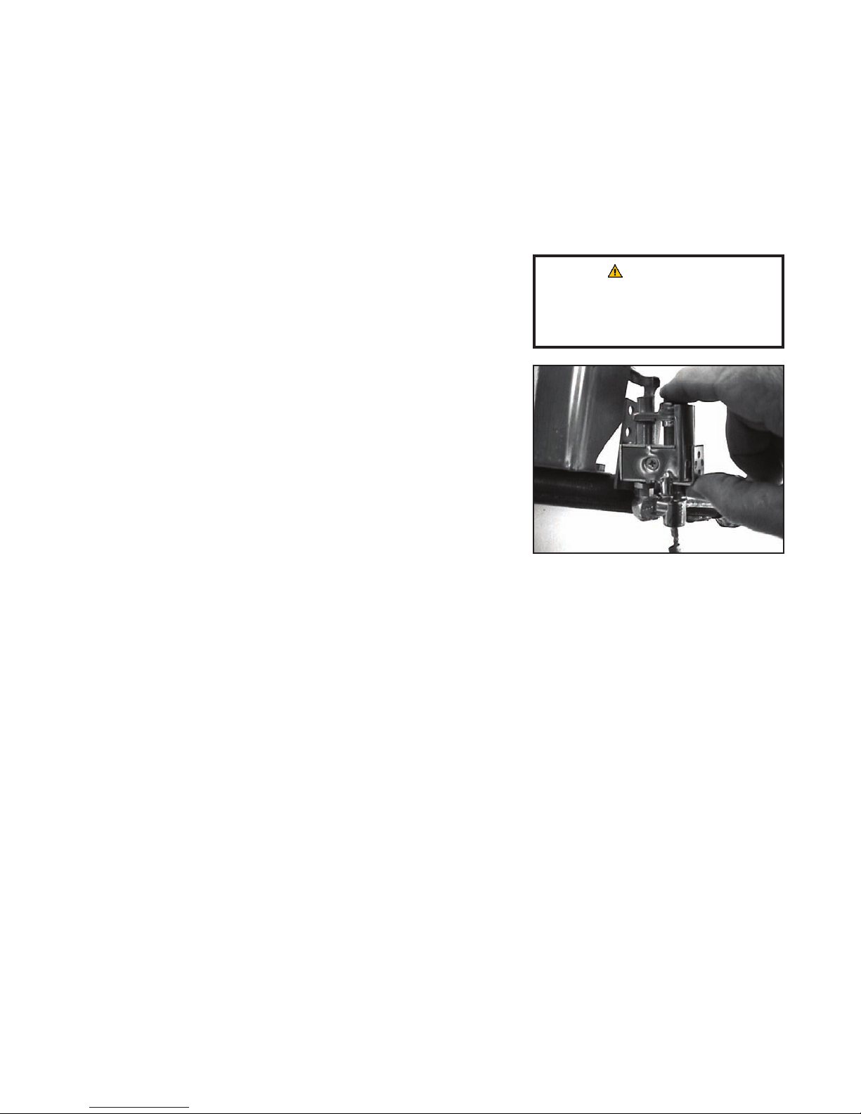
After servicing is complete:
Remove this plug and
connect a manometer or
pressure gauge to the
port.
5. Return the fryer to its original location, reconnect the unit to the gas supply, and open the gas supply
valve. Be sure to reattach all restraining devices and plug in all electrical cords.
6. Rellthefryerwithoil.
1.3 Diagnostic Procedures
1.3.1 Cleaning the Gas Valve Vent Tube
1. Carefullyunscrewtheventtubefromthegasvalve.
NOTE:Straightentheventtubeforeasyremoval.
2. Pass a piece of binding wire (.052-inch diameter) or equivalent through the tube to remove
obstructions.
3. Removethewireandblowthroughthetubetoensurethatitisclear.
4. Reinstallthetubeandbenditsothattheopeningispointingdown.
1.3.2 Checking the Burner Manifold Gas Pressure
1. Ensurethatthegasvalveknoborbutton isin theOFF
position.
2. Removethepressuretapplugfromtheendofthemanifold.
The frypot must be lled
with oil or water during this
WARNING
procedure.
3. Connectamanometerorpressuregaugetotheport.
4. PlacethegasvalveinthePILOTpositionandlight.Whentheburnerlightsandcontinuestoburn,
notethegaspressurereadingandcompareittotheaccompanyingtables.
To adjust burner gas pressure:
5. Onnon-CEvalves,removethecapfromtheregulatoradjustmentscrew.
6. Onallunits,increasethesettingonthethermostatuntiltheburnercomeson.
7. Monitorthegaspressurereadingonthemanometerorpressuregauge.
1-3
Page 9
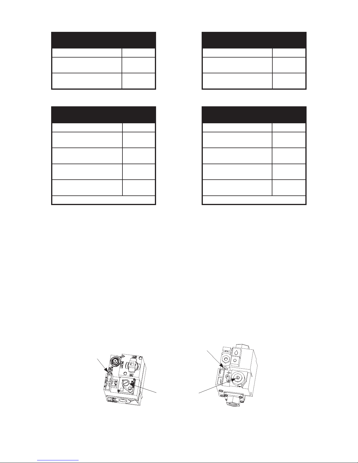
To access the pilot adjustment
screw on non-CE valves, this cap
must be removed.
Pilot Adjustment Screw
Honeywell Valve
(Non-CE Units)
Honeywell Valve
(CE Units)
Gas Valve Regulator
Adjustment Screw
35-Series Non-CE Standard
Burner Manifold Gas Pressures
Gas Pressure
Natural
Propane
4.0” W.C.
0.87 kPa
9.0” W.C.
2.24 kPa
35-Series CE Standard
Burner Manifold Gas Pressures
Gas Pressure
Natural Gas Lacq
(G20) under 20 mbar
Natural Gas Gronigue*
(G25) under 25 mbar
Natural Gas Gronigue*
(G20) under 20 mbar
Propane
(G31) under 37 or 50 mbar
* Belgian G25 and G20 = 9.0 mbar
9 mbar
11 mbar
11 mbar
22.5 mbar
45-Series Non-CE Standard
Burner Manifold Gas Pressures
Gas Pressure
Natural
Propane
45-Series CE Standard
Burner Manifold Gas Pressures
Gas Pressure
Natural Gas Lacq
(G20) under 20 mbar
Natural Gas Gronigue*
(G25) under 25 mbar
Natural Gas Gronigue
(G20) under 20 mbar
Propane
(G31) under 37 or 50 mbar
* Belgian G25 = 7.0 mbar
3.5” W.C.
0.73 kPa
8.25” W.C.
2.05 kPa
7.5 mbar
10 mbar
10 mbar
20.6 mbar
8. Use a at-head screwdriver to adjust the gas valve regulator adjustment screw to obtain the prescribed
pressure written on the rating plate or one of the charts above. (Use the diagram on below to locate
this screw.) Turn the screw clockwise to increase gas pressure and counterclockwise to decrease gas
pressure.
9. On non-CE units, reinstall the gas valve regulator cap screw when the correct manifold pressure is
obtained.
10. Place the gas valve in the OFF position. Remove the tting from the pressure tap hole and reinstall the
pressure tap plug.
11. Place the gas valve in the PILOT position. Re-light and check for any gas leaks.
12. Place the gas valve in the OFF position.
Locating the gas valve regulator adjustment screw and pilot adjustment screw.
1-4
Page 10
1.3.3 Adjusting the Pilot Flame
There should be approximately ¾-inch spacing between the top edge
of the targets and the side of the frypot.
¾-inch
1. On non-CE valves, remove the cap covering the pilot adjustment screw. On all valves, use a attipped screwdriver to turn the pilot adjustment screw counterclockwise to increase the length of the
ame or clockwise to decrease the length of the ame. (Use the diagram on the previous page to
locate this screw.) Adjust the ame to a length of 1- to 1½- inches (25 to 38 mm).
2. On non-CE valves, reinstall the pilot adjustment screw cap.
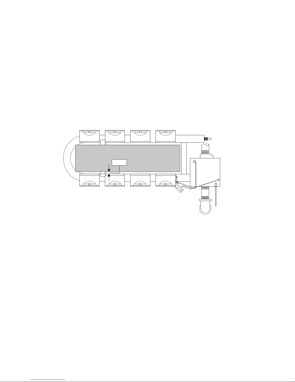
1.3.4 Adjusting Burner Ceramic Target Spacing and Alignment
Proper spacing of the top edge of the ceramic targets is ¾-inch (13 mm) from the frypot side. To adjust
target spacing, bend the brackets away or toward the frypot, as needed. A length of board ¾-inch thick is
useful as a gauge to verify spacing and alignment.
1.3.5 Calibrating the Thermostat
Fryers with thermostat access doors:
1. Fill the frypot to the lower OIL-LEVEL line with cooking oil. If using solid shortening, pack it
tightly into the frypot before starting the calibration procedure.
2. Light the pilot. (See Chapter 3 of the Installation and Operation manual for detailed lighting
instructions.)
3. Insert a thermometer or pyrometer into the frypot, about 1-inch from the thermostat.
4. Open the thermostat access door and set the thermostat on the fryer to 325°F (162°C).
5. When oil reaches 325°F (162°C), allow the burners to cycle on and off three times.
6. Take a temperature reading when the burners go off for the third time.
7. Loosen the setscrews in the thermostat knob and turn the knob to the temperature established by the
thermometer/pyrometer reading.
1-5
Page 11

8. Allow the burners to cycle on and off three more times and recheck the thermometer/pyrometer reading
against the thermostat setting. Temperature readings should be within 5°F (2.8°C) of setpoint.
Fryers with thermostat control panels:
NOTE: Remove the thermostat knob from its shaft to allow the control panel to hinge downward.
Follow the instructions in Section 1.4.2 to remove the knob and control panel.
1. Fill the frypot to the lower OIL-LEVEL line with cooking oil. If using solid shortening, pre-melt it
before starting the calibration procedure.
2. Ensure the fryer power switch is in the OFF position, and light the pilot. (Refer to Chapter 3 of the
Installation and Operation manual for detailed lighting instructions.)
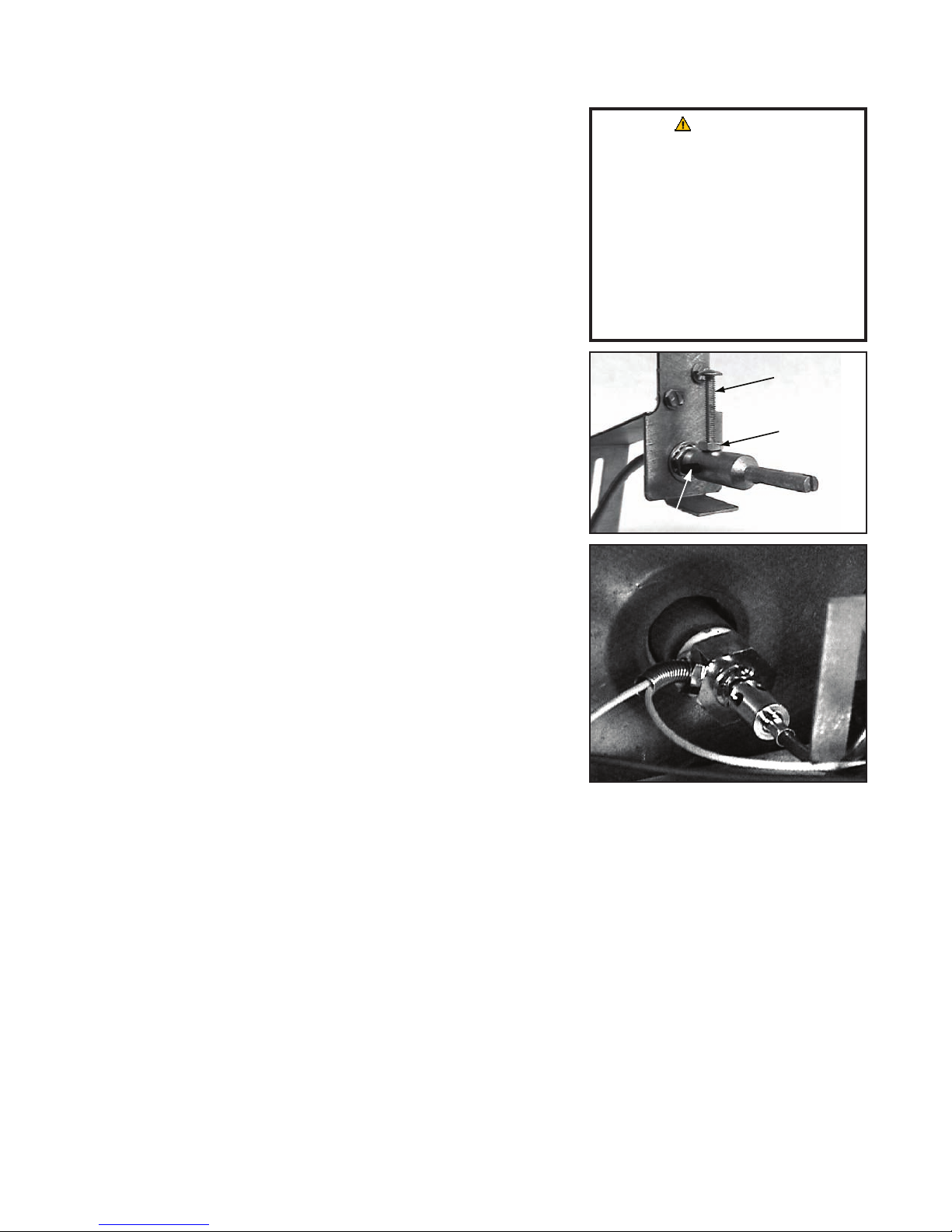
3. Insert a thermometer or pyrometer into the frypot so that it
touches the thermostat guard.
The thermostat exible shaft
CAUTION
must not be rotated while
4. Loosen the setscrew and stop screw securing the thermostat
shaft extension to the exible shaft. Remove the extension to
installing the thermostat
shaft extension!
expose the slot in the end of the exible shaft.
5. Place the fryer power switch in the ON position.
NOTE: If the burner does not light at this time, it does not
mean the thermostat is defective.
Use a small at-head screwdriver to
slowly turn the exible shaft counterclockwise until the burner
Do not rotate the exible shaft
more than two turns in either
direction. Doing so will cause
damage to the thermostat.
lights.
6. When the oil temperature reaches 325°F (162°C), slowly turn the exible shaft clockwise until the
burner turns off. Then, allow the fryer to sit for a few minutes.
7. Repeat Steps 5 and 6 at least three times to ensure that the setting is accurate. The thermostat control
is considered properly calibrated if the burner lights when the cooking oil cools to 325°F (162°C).
Do not take the reading when the burner shuts off after raising the temperature.
8. Once the thermostat is calibrated, allow the burner to cycle on and off at least three times to ensure
that it lights at the correct temperature.
9. After the calibration is complete, place the fryer power switch in the OFF position and disconnect
the fryer from the electrical supply.
10. Carefully replace the thermostat shaft extension so that the stop screw points straight up. Without
rotating the exible shaft, tighten the stop screw, locking nut, and setscrew.
11. Close the fryer control panel and replace the screws and bezel.
12. Reinstall the thermostat knob. Align its pointer with the 325°F (162°C) index mark on the temperature
dial.
13. Reconnect the fryer to the electrical supply.
1-6
Page 12

1.3.6 Testing the Temperature Probe
1. While it is still in the frypot, inspect the probe body for damage. Inspect the leads for fraying,
burning, breaks, or kinks. If the probe is bent, dented, or cracked, or if the leads are damaged, replace
the probe.
2. Determine the temperature of the cooking oil using a thermometer or pyrometer placed at the tip of
the probe.
3. Disconnect the 15-pin wiring harness from the interface board. Measure the probe resistance using
J2 pins 13 and 14.
4. Resistance should approximately equal the given probe resistance for the corresponding temperature
on the chart in Section 1.6, Page 1-23. If not, the probe has failed and must be replaced. Probes
cannot be calibrated.
NOTE:
A defective probe will cause inaccurate temperature measurements. If the temperature,
as measured by the probe, varies by more than 5°F! (2.8°C!) from the thermometer or pyrometer
reading, the probe should be replaced. Temperature probes cannot be calibrated.
1.4 Replacing Fryer Components
1.4.1 Replacing a Controller or Computer
1. Disconnect the fryer from the electrical power supply.
2. Slide the metal bezel up to disengage the lower tabs. Then, slide the bezel down to disengage the
upper tabs.
3. Remove the two screws holding the controller to the control panel frame.
4. Hinge the controller down to access the 15-pin wiring harness on the back and unplug it.
5. Lift the controller up and out of the hinged tab slots.
6. Use a 5/16-inch nut driver (P/N 802-0352) to remove the nut and green grounding wire from the back
of the controller.
7. If replacing the 15-pin wiring harness, do so now. Plug the new 15-pin wiring harness into the
interface board with the metal ring on the controller-end of the connector.
8. Connect the 15-pin wiring harness and the green ground wire to the new controller. When the
connector on the harness is completely engaged, the clips on either side will snap into place.
9. Re-hinge the controller by inserting the tabs on the bottom into the slots on the control frame panel.
10. Move it into the closed position against the control panel frame and replace the screws in the top
corners.
11. Insert the top tabs on the bezel into the slots on the underside of the top cap. Slide the bezel down to
engage the lower tabs in the lower slots.
1-7
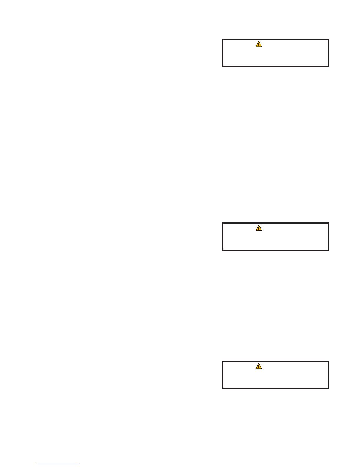
Page 13
1.4.2 Replacing the Operating Thermostat in Units with Thermostat Control Panels
stop screw
locking nut
setscrew
1. Disconnect the fryer from the electrical power supply. Turn
off the gas and disconnect the fryer.
2. Drain the frypot.
3. Loosen the setscrew securing the thermostat knob and remove
the knob. Remove the screws from the upper left and right
corners of the control panel. The control panel hinges at the
bottom and will swing open from the top.
4. Disconnect the 9-pin wiring harness and remove the control
panel from the fryer by disengaging its tabs from the hinge
slots in the mounting frame.
5. Loosen the setscrews securing the exible shaft to the thermostat
shaft. Slip the exible shaft off the thermostat shaft.
6. Remove the exible shaft guide by removing the two sheet
metal screws securing it to the upper frame.
7. Disconnect the thermostat leads from pin 14 in the 20-pin
terminal block and from the gas valve terminal.
CAUTION
The thermostat exible shaft
must not be rotated while
installing the thermostat
shaft extension!
Do not rotate the exible shaft
more than two turns in either
direction. Doing so will cause
damage to the thermostat.
NOTE: If the fryer has a melt cycle, the thermostat leads
connect to the PC board rather than to the terminal block and
gas valve. Disconnect the leads from the PC board if this is
the case.
8. Unscrew the thermostat from the frypot and remove it.
9. Apply Loctite™ PST56765 thread sealant or equivalent to the
threads of the replacement thermostat.
10. Reverse Steps 1-8 to install the replacement thermostat.
Loosen these setscrews and slip the
exible shaft off of the thermostat shaft.
1.4.3 Replacing the Operating Thermostat in Units with Thermostat Access Doors
1. Disconnect the fryer from the electrical power supply. Turn off the gas and disconnect the fryer.
2. Drain the frypot.
3. Use an allen wrench to loosen the setscrew at the side of the thermostat knob. Remove the knob.
4. Remove the two setscrews on both sides of the thermostat shaft and remove the dial plate.
5. Disconnect the thermostat wires from the gas valve.
6. Use a slotted socket to unscrew the thermostat from the frypot.
7. Apply Loctite™ PST56765 thread sealant or equivalent to the threads of the replacement thermostat.
8. Reverse Steps 1-7 to install the replacement thermostat.
1-8
Page 14
1.4.4 Replacing the Temperature Probe
1. Disconnect the fryer from the electrical supply.
CAUTION
Drain the frypot before pro-
2. Drain the frypot.
ceeding.
3. Remove the controller or computer according to the instructions in Section 1.4.1.
4. Unplug the 12-pin wiring harness from the front of the interface board.
5. Use a pin-pusher to remove the temperature probe wires (pins 1 and 2) from the 12-pin wiring harness
6. Unscrew the temperature probe from the frypot and remove.
7. Apply Loctite™ PST56765 thread sealant or equivalent to threads of the replacement probe.
8. Screw the new probe into the frypot.
9. Reverse Steps 1-5 to reassemble.
10. Check the probe according to the instructions in Section 1.3.6.
1.4.5 Replacing the High-Limit Thermostat in Fryers with Thermostat Controls
1. Disconnect the fryer from the electrical supply.
CAUTION
Drain the frypot before pro-
2. Drain the frypot.
ceeding.
3. Remove the thermostat knob and/or control panel as instructed in Section 1.4.2 or 1.4.3.
4. Disconnect the high-limit thermostat leads from the gas valve pilot coil.
5. Unscrew the high-limit thermostat from the fryer and remove.
6. Apply Loctite™ PST56765 thread sealant or equivalent to the threads of the replacement high-limit
thermostat.
7. Reverse Steps 1-5 to the install replacement high-limit.
1.4.6 Replacing the High-Limit Thermostat in Fryers with Other Controls
1. Disconnect the fryer from the electrical supply.
CAUTION
Drain the frypot before pro-
2. Drain the frypot.
ceeding.
3. Remove the bezel and controller as instructed in Section 1.4.1, Steps 2 and 3.
4. Unplug the 15-pin wiring harness and grounding wire from the controller.
5. Remove the high-limit thermostat wires from the gas valve pilot coil.
1-9
Page 15

6. Unscrew the high-limit thermostat from the fryer and remove it.
7. Attach the appropriate terminals (instructions furnished in the replacement kit) to the thermostat
leads.
8. Apply Loctite™ PST56765 thread sealant or equivalent to the threads of the replacement high-limit
thermostat.
9. Reverse Steps 1-6 to install the replacement high-limit.
1.4.7 Replacing the Heat Mode Indicator Light in Fryers with Thermostat Controls
1. Disconnect the fryer from the electrical power supply.
2. Remove the thermostat knob and control panel as instructed in Section 1.4.2 or 1.4.3, as appropriate.
3. Carefully press the light out from the back of the control panel.
4. Disconnect one wire at a time and reconnect it to the replacement light (before disconnecting the
next wire). Continue until all wires are transferred.
5. Carefully press the light back into the control panel.
6. Reinstall the thermostat knob and control panel by reversing Step 2.
7. Reconnect the fryer to the electrical power supply.
1.4.8 Replacing the Power or Melt Cycle Switch in Fryers with Thermostat Controls
1. Disconnect the fryer from the electrical power supply.
2. Remove the thermostat knob and control panel as instructed in Section 1.4.2.
3. Using a at-head screwdriver, disconnect the chrome bezel from the tabs on the switch and press the
switch out from the front.
4. Carefully press the new switch into the chrome bezel, making sure the tabs on the switch engage the
slots in the bezel.
5. Disconnect one wire at a time and reconnect it to the replacement switch (before disconnecting the
next wire). Continue until all wires are transferred.
6. Reinstall the thermostat knob and control panel by reversing Step 2.
7. Reconnect the fryer to the electrical power supply.
1-10
Page 16

1.4.9 Replacing Burner Ceramic Targets
1. Disconnect the fryer from the electrical power supply. Turn off the gas and disconnect the fryer.
2. Drain the frypot or remove the handle from the drain valve.
WARNING
Drain the frypot or remove the
3. Remove the round drain sections as necessary to expose the
burners and heat shield.
handle from the drain valve
before proceeding further.
4. Disconnect the wires from the gas valve terminal block, marking each wire to facilitate reconnection.
5. Remove the high-limit thermostat wires from the gas valve pilot coil.
6. Disconnect the pipe union collar located on the bottom of the gas valve.
7. Remove the burner heat shield hanger screws at the front of the burner and remove the heat shield.
In units with built-in ltration, there may be a second heat shield located under the burner manifold.
Remove the screws holding it in place and remove it.
8. Remove the lter pan by sliding it out of the unit and lifting it up and out of the roller track.
9. Remove the burner hanger screws and lower the front of the main burner. Pull it forward to clear the
rear burner hanger and lower the burner to the oor.
10. Raise the front of the fryer enough to slide the burner from under the fryer cabinet.
11. To replace only the ceramic targets, straighten the target
locking tabs with a pair of needle nose pliers or a screwdriver
and slide the target up and off the bracket. Slide the
replacement target onto the bracket and bend the locking tabs
down.
Avoid cross-threading and
stripping when reinstalling
the brass orices.
CAUTION
To replace the entire target assembly, use a ½-inch (13mm) box end wrench to remove the two brass
orices that hold the assembly to the burner manifold. Position the new assembly and replace the
orices.
12. Reverse Steps 1-9 to reinstall the burner assembly. Compare spacing and alignment of targets with
the parameters in Section 1.3.4.
1.4.10 Replacing the Gas Valve
1. Disconnect the fryer from the electrical power supply. Turn
off the gas and disconnect the fryer.
Drain the frypot or remove the
WARNING
handle from the drain valve
2. Drain the frypot or remove the handle from the drain valve.
before proceeding further.
3. Disconnect the wires from the gas valve terminal block, marking each wire to facilitate reconnection.
1-11
Page 17
4. Remove the high-limit thermostat wire from the gas valve pilot coil.
5. Disconnect the pilot gas line tting from the gas valve.
6. Disconnect both pipe union collars from the gas valve and remove the valve.
7. Remove the pipettings from the old gas valve and install them on the replacement valve. Use
Loctite™ PST56765 or equivalent pipe thread sealant on the threads.
8. Reverse Steps 1-6 to install the replacement gas valve.
1.4.11 Replacing the Pilot Assembly or Thermopile
WARNING
Drain the frypot or remove the
1. Remove the burner assembly in accordance with Steps 1-10
in Section 1.4.9.
handle from the drain valve
before proceeding further.
2. To replace only the thermopile:
a. Bend the clip at the bottom of the pilot assembly and press
the thermopile out of the pilot assembly from the top.
b. Disconnect the thermopile tting from the gas valve pilot coil.
c. Reverse Steps a and b to install the replacement thermopile.
3. To replace the complete pilot assembly:
Bend the clip to release the thermopile.
a. Disconnect the pilot tubing from the bottom of the pilot assembly.
b. Remove the screw from the pilot mounting bracket to release the pilot assembly.
c. Disconnect the thermopile tting from the gas valve pilot coil.
d. Reverse Steps a-c to install the replacement assembly.
4. Reinstall the burner assembly by reversing Steps 1-8 of Section 1.4.9.
1.4.12 Replacing the Frypot
1. Drain the frypot.
2. Disconnect the fryer from the electrical power supply. Turn off the gas supply and disconnect the
fryer.
3. Remove all accessories (i.e., frypot covers, basket lift arms, etc.) from the fryer.
4. If the fryer is equipped with a thermostat control, remove the thermostat knob and control panel
according to Steps 3-8 in Section 1.4.3.
NOTE: If the fryer is congured with a melt cycle, the thermostat leads will be connected to the PC board
rather than to the terminal block and gas valve. Disconnect the leads from the PC board if this is the case.
1-12
Page 18

5. If the fryer is not equipped with a thermostat control, remove the controller according to Steps 2-6
in Section 1.4.1.
6. Disconnect the 12-pin plug from the interface board. Use a pin-pusher to remove the temperature
probe wires (pins 1 and 2) and the high-limit thermostat leads (pins 6 and 8) from the plug. Leave
all other wires connected.
7. Remove the control panel frame by removing the screws in the upper left and right corners that
secure the control panel to the topcap. Remove the screws in the top and bottom holes of each brace
of the control panel that secure it to the fryer. Pull the control panel straight out of the fryer frame.
It may require a rubber mallet to loosen it.
8. Disconnect the wires from the components in the component shield and mark to facilitate reconnection.
9. Disconnect the wires from the gas valve terminal block and mark each to facilitate reconnection.
10. Remove the cover from the drain safety switch, disconnect the wires from the switch, and pull them
out of the switch box.
11. Pull up and forward on the component shield to clear the rear mounting stud on the front of the
frypot and remove it from the fryer by rotating its right side up and to the left.
12. Disconnect the pipe union on the bottom of the gas valve.
13. On units with ltration, disconnect the section of drain connected to the drain valve of the frypot to
be removed.
14. Take off the topcap by removing the pairs of screws from each tab in the upper corners. Pull up to
slide it off the fryer. It may require a rubber mallet to loosen it.
15. Remove the frypot hold-down bracket, which attaches the front of the frypot to the frame of the fryer.
It is held in place by three screws: two securing it to the frame and one securing it to the frypot.
16. Remove the ue cap:
CAUTION
a. Remove all of the screws attaching the back panels to the
fryer and remove the panels.
Clean all threads and apply
Loctite™ PST56765 thread
sealant or equivalent when
b. Remove the screws in the bottom left and right corners of
the ue cap.
c. Slide the ue cap up to remove it.
installing the drain valve,
high-limit, and thermostat
or temperature probe on the
replacement frypot.
17. Remove the oil return line from the front of the frypot to be removed.
18. Lift the complete frypot assembly (frypot, burner, gas valve, and ue) from the fryer cabinet.
19. Transfer the burner heat shield and burner to the replacement frypot.
20. Remove
the drain valve, thermostat or temperature probe, and high-limit thermostat and install them
on the replacement frypot.
1-13
Page 19

21. In units with multiple frypots, add a bead of silicon along the joint between the frypots to ensure a
seal. Then, insert the top connecting strip.
22. Reverse Steps 1-25 to reassemble the fryer.
1.5 Troubleshooting and Problem Isolation
Because it is not feasible to include every issue that might occur, this section is intended to provide
technicians with a general knowledge of the broad problem categories associated with this equipment
and the probable causes of each. With this knowledge, the technician should be able to isolate and correct
any problem encountered.
1.5.1 Typical Problems
You are likely to encounter problems in these broad categories:
1. Pilot Failure
2. Ignition Failure
3. Improper Burner Function
4. Improper Temperature Control
6. Computer Malfunction
7. Filtration Malfunction
8. Leakage
9. Basket Lift Malfunction
5. Gas Valve Malfunction
Read the following sections to learn more about each category. A series of troubleshooting guides is
also included at the end of the chapter to assist in identifying some of the more common problems. In
addition, Section 1.5.2 will guide technicians through interpretation of digital controller lights, helpful
in diagnosing problems.
Pilot Failure
There are two types of pilot failure: no pilot ame and unreliable pilot ame.
No pilot ame:
• Insufcient gas supply
• Clogged pilot orice
• Air in gas lines (usually in new installations).
Unreliable pilot ame:
• Open or grounded high limit
• Loose or corroded wire connections
• Low or no voltage out of thermopile
• Bad gas valve.
Ignition Failure
Ignition failure occurs when the gas valve no longer receives power, the gas supply stops, or the pilot
ame goes out. Solid-state controllers indicate ignition failure by illuminating the heat light and trouble
light simultaneously. Computers and digital timers will read HELP to indicate ignition failure. There
are three primary areas of focus in diagnosing and correcting ignition failure:
1. The gas and electrical power supplies
2. The electronic circuits
3. The gas valve.
1-14
Page 20

The Gas and Electrical Power Supplies
The main indicators that the gas or electrical power supply is the cause of ignition failure are as follows:
an entire battery of fryers fails to light, and/or there are no indicator lights illuminated on the fryer
experiencing ignition failure. Verify that the quick disconnect hose is properly connected, the fryer is
plugged in, the main gas supply valve is open, and the circuit breaker for the fryer electrical supply is
not tripped.
The Electronic Circuits
If the fryer is receiving gas and electrical power, the next most likely cause of ignition failure is a problem
in the 24 VAC circuit of the pilot system. If the fryer is equipped with a drain valve for ltration purposes,
check the drain valve to verify that it is fully closed. A microswitch attached to the valve must be closed
for power to reach the gas valve. Often, although the valve handle appears to be in the closed position, the
microswitch is still open. If the valve is fully closed, or the fryer is not equipped with a ltration system,
refer to Troubleshooting the 24 VAC Circuit in Section 1.7.1 of this manual.
The Gas Valve
If the problem is not in the 24 VAC circuit of the pilot system, it is most likely in the gas valve. However,
before replacing the gas valve, refer to Troubleshooting the Gas Valve in Section 1.7.2 of this manual.
Improper Burner Function
In these types of instances, the burner ignites but exhibits abnormal characteristics, such as popping,
incomplete lighting of the burner, uctuating ame intensity, and ames “rolling” out of the fryer.
Popping indicates delayed ignition. In most cases, the main gas valve is opening, but the burner is not
immediately lighting. When ignition does take place, excess gas bursts into ame suddenly, rather than
smoothly igniting.
The primary causes of popping are:
1. Incorrect or uctuating gas pressure
2. Misdirected or weak pilot ame
3. Clogged burner orices
4. Inadequate make-up air
5. Missing or misaligned burner deector targets
6. Clogged vent tube (causing incorrect gas pressure).
Incorrect or Fluctuating Gas Pressure
If popping occurs only during peak hours, the problem may be incorrect or uctuating gas pressure.
Verify that the incoming gas pressure (to the gas valve) is in accordance with the appropriate CE or non-
CE standard found in the table on Page 1-4 and the pressure remains constant throughout all hours of
usage. Refer to Checking the Burner Manifold Pressure in Section 1.3.2 for instructions on checking the
pressure of gas supplied to the burner.
1-15
Page 21

Misdirected or Weak Pilot Flame
If popping is consistent during all hours of operation, check position of the pilot above the burner orice
and verify that the pilot pressure is correct. A 1- to 1 ½-inch (25 to 38 mm) ame indicates correct pilot
pressure. Refer to Section 1.3.3 for information on pilot ame adjustment.
Clogged Burner Orices
Clogged burner orices, especially those near the pilot, are also likely causes of delayed ignition. Lack of
ame, ames that are orange in color, and ames that shoot out at an angle from the rest are indications
of clogged burner orices. If only one side of the burner is lighting, the rear deector target may be
misaligned or missing completely. Improper burner pressure may also cause this. If there are gaps in
burner ring, check for clogged burner orices.
Inadequate Make-up Air
Another cause of popping is an insufcient air supply or drafts that are blowing the pilot ame away
from the burner. Check for negative pressure conditions in the kitchen area. If air is owing into the
kitchen area, this indicates that more air is entering the kitchen than is leaving it. In a negative pressure
environment, the burners may not be receiving an adequate amount of air to maintain a strong pilot
ame.
Other Causes of Popping
Other causes of popping are more ambiguous and may have two or more possible causes to consider.
If the fryer’s gas and air supplies are okay, it is likely that the cause of the popping is one of the electrical
components. Examine the controller for signs of melting, distortion, and possibly discoloration due to
excessive heat buildup in the fryer (usually indicating improper ue performance). Automatically suspect
a discolored or distorted controller and replace it. However, it is important to diagnose and correct the
condition causing excessive heat in the fryer or the problem is likely to recur.
Fluctuating ame intensity is normally caused by improper or uctuating gas pressure or the result
of variations in the kitchen atmosphere. Verify incoming gas pressure in the same way as for popping,
discussed in the preceding paragraphs. Air condition and ventilation units (such as hoods) starting and
stopping throughout the day usually cause variations in the kitchen atmosphere. As they start and stop,
the pressure in the kitchen may change from positive or neutral to negative, or vice versa. They may also
cause changes in airow patterns that may affect ame intensity.
Flames “rolling” out of the fryer are usually an indication of negative pressure in the kitchen. The
negative air pressure is sucking air out of the fryer enclosure and the ames are following the air. If
negative pressure is not the cause, check for high burner manifold gas pressure in accordance with the
procedures in Section 1.3.2. An obstructed ue, which prevents the fryer from properly exhausting, may
also be the cause.
An unusually noisy burner, especially when ames are visible above the ue opening, may indicate
that the burner gas pressure is too high or that the gas valve vent tube is blocked. If the gas pressure is
correct and the vent tube is unobstructed, the gas valve regulator is probably defective.
1-16
Page 22

Occasionally, a burner may appear to be operating correctly, but it shows a slow recovery rate (discussed
on Page 1-18). The primary causes of this are low burner manifold pressure and misaligned or missing
deector targets. In some cases, the cause is a gas valve regulator that is out of adjustment. Refer to
Section 1.3.2 for instructions on checking the burner manifold pressure and Section 1.3.4 for adjusting
deector target positioning.
Improper Temperature Control
Temperature control—including that for the melt cycle—is a function of several interrelated components,
each of which must operate correctly. The principal component is the thermostat (in units equipped
with thermostat controls) or the temperature probe (in fryers equipped with other types of controllers).
Depending upon the specic conguration of the fryer, it may also include an interface board and
controller. Problems with improper temperature control can be categorized into those issues concerning
melt cycle malfunctions and those concerning a failure to control at setpoint.
Melt Cycle
In fryers equipped with thermostat controls, the melt cycle is controlled with a solid state melt cycle
board and a melt cycle switch on the control panel. In all cases, replace the defective component.
In fryers equipped with other types of controllers, the problem may originate in the controller, the
temperature probe, or a malfunctioning heat relay on the interface board. For problem isolation techniques,
refer to the troubleshooting guides, Troubleshooting the Thermostat and Troubleshooting the Temperature
Probe, in Section 1.7, Troubleshooting.
Failure to Control at Setpoint
In fryers equipped with thermostat controls, the problem will be in the thermostat. Refer to Section 1.3.5
for instructions on calibrating the thermostat. Possible causes are that
• the thermostat is out of calibration,
• the knob or exible shaft is loose on the thermostat shaft,
• a thermostat wire is disconnected or broken, or
• the thermostat is defective.
Refer to Section 1.3.5 for instructions on calibrating the thermostat. In fryers equipped with other types
of controls, the problem may originate in the temperature probe or probe circuit, the interface board, or
the controller. Refer to Troubleshooting the Temperature Probe, Section 1.7.4., for problem isolation
techniques.
Gas Valve Malfunction
Occasionally, a gas valve may malfunction. Use Section 1.7.2, Troubleshooting the Gas Valve, to
determine if the valve has failed.
Computer Malfunction
Before diagnosing problems related to a computer controller, it is important to understand the use and
signicance of sensitivity and recovery.
1-17
Page 23

Sensitivity and Recovery
Sensitivity—or “stretch time”—is a programmable feature, patented by Frymaster, which increases or
decreases the cook time countdown based on variation in the oil temperature from the setpoint. The
sensitivity for each product button has ten settings, 0-9. Setting sensitivity to “0” will disable the feature
completely, while a setting of “9” will provide the highest sensitivity or most change. The correct
sensitivity for any product is based on the type of product, its density, the setpoint temperature, and the
customer’s own requirements. A generic sensitivity chart is located on Page 1-5 of the Frymaster Fryer
Controllers manual (P/N 819-5916).
Recovery—or “rate of rise”— is a method of measuring a fryer’s performance. It is the time required for
the fryer to increase the oil temperature from 275°F to 325°F (135°C to 163°C). This range is the standard
since ambient kitchen temperatures can affect the test if lower ranges are used. The Computer Magic
computer controller performs the recovery test each day as the fryer heats-up. An operator can view the
results of the test any time the fryer is above 325°F (163°C) by pressing the button and entering the
code 1652. The test results display in the computer’s LED panel in minutes and seconds. The acceptable
recovery time is 2:30 or less. Extended recovery is a sign that the fryer is not being regularly maintained
or it is in need of servicing. The recovery time lengthens as fryer health declines. This is a useful tool for
gauging the condition of the fryer and should be checked regularly.
Common Computer Complaints
Most problems with Computer Magic controllers stem from programming issues. There are four common
complaints.
1. Fryer constantly displays HI.
Cause: Incorrect, low, or missing setpoint.
Fix: Press 1650, enter the correct setpoint using the keypad, then press to lock-in the new
setpoint.
2. Fryer constantly displays temperature.
Cause: The computer has been programmed to constantly display the temperature.
Fix: Press 165L.
3. Fryer displays temperature in Celsius.
Cause: The computer has been programmed to display in Celsius rather than Fahrenheit.
Fix: Press 1658.
4. Computer times down too slowly or too quickly.
Cause: The computer is compensating for oil temperature via the sensitivity setting.
Fix: Reprogram the sensitivity setting for each product by following the programming instructions in
the Installation and Operation manual or the Frymaster Fryers Controllers manual (P/N 819-5916).
1-18
Page 24
Filtration Malfunction
Up for reverse
Sediment
Particle
Oil Flow
Down for forward
Sediment
Particle
The majority of ltration malfunctions arise from operator error. One of the most common errors is
placing the lter paper on the bottom of the lter pan rather than over the lter screen.
Inspect the lter paper to ensure that it is correctly sized and placed. Incorrectly sized or installed lter
paper will allow particles and sediment to pass through the lter pan and into the pump. When sediment
enters the pump, the gears can bind and cause the motor to overheat. If the motor overheats, the thermal
overload will trip to protect the motor from further damage. Reset the motor by pressing the red reset
button the end of the motor nearest the operator. Sediment cannot enter the pump when the correct
lter paper is used properly.
While you are checking the lter paper, verify that the O-rings on the lter pan and connectors are
present and in good condition. Missing or worn O-rings will allow the pump to suck air and decrease its
efciency.
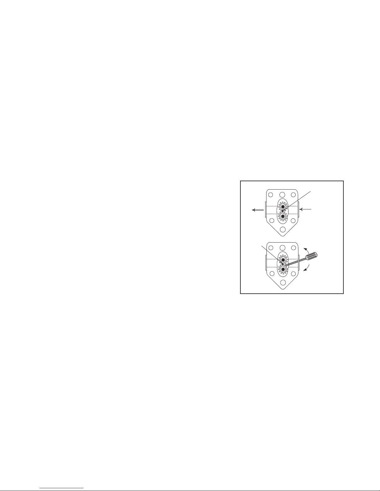
A pump seized by debris or hard shortening can usually be freed by manually moving the gears with a
screwdriver or other tool.
1. Disconnect power to the lter system.
2. Remove the input plumbing from the pump.
3. Use a screwdriver to manually turn the gears.
• Turn the pump gears backward to release a hard particle
and remove it.
• Turn the pump gears forward to push softer objects and
solid shortening through the pump and allow the gears to
move freely.
Removing debris or shortening from
a seized pump.
Incorrectly sized or installed paper will also allow food particles and sediment to pass through and clog
the suction tube on the bottom of the lter carriage. Particles large enough to block the suction tube may
indicate that the crumb tray is not being used during ltering.
Pan blockage can also occur if shortening remains in the pan and solidies. The heater strip on the
suction tube prevents solidication of residual shortening left in the tube. It will not melt or prevent
solidication of shortening in the pan. Remove blockages by forcing the item out with an auger or drain
snake. Compressed air or other pressurized gases should not be used to force out the blockage.
The Power Shower may need service for clogged openings, shortening solidied in the tubes, missing
clean-out plugs, and missing or worn O-rings. To correct these problems, clean the unit and replace
missing or worn plugs and O-rings.
1-19
Page 25

Leakage
When a frypot appears to be leaking, suspect the areas where high-limit thermostats, temperature probes,
and drain ttings attach to the frypot. When installed or replaced, seal each of these components with
Loctite PST56765 sealant or equivalent to prevent leakage.
If oil coats the sides or ends of the frypot, the most likely cause is spillage over the top of the frypot.
There may also be oil pooled on the oor below the fryer. This is not necessarily a sign that the frypot
is leaking.
It is important to check the joints between round drain sections and all of the ttings. If removing a section
of drain tube connected to the drain valve for any reason, make sure that the O-rings are in good condition
and properly tted within the drain during reinstallation. Ensure that the clamps are tight and that the
nut holding them onto the stud of the tube is not stripped or loose. Also, check that the drain tube runs
downward from the drain along its whole length and has no low points where oil may accumulate.
In very rare cases, a leak may develop along one of the welded edges of the frypot. When this type of leak
is suspected, thoroughly inspect the frypot. If it is denitely leaking, replace the frypot.
Basket Lift Malfunction
Performance Pro series gas fryers may be optionally equipped with automatic basket lifts to ensure uniform
cooking time. The lifts can be controlled manually or through a basket lift timer or Computer Magic
computer. Basket lifts will always come in pairs, although each operates independently.
Each basket lift consists of a basket lift arm attached to a toothed rod, a reversible-drive gear motor, and
a pair of roller-activated microswitches. The gear motor engages the teeth on the rod and moves it up or
down based on the motor’s rotation. Microswitches at the upper and lower limits of movement stop the
motor when the basket is fully up or down. They also reverse the direction of current ow to reverse the
motor direction. When the manually set or programmed cooking time has elapsed, the basket lift receives
current and raises the basket out of the oil.
In units congured for manual (push-button) controls, a mechanical or electrical timer controls voltage
to the system. Turning a rotary knob sets the cook time, and pressing the button in the middle of the knob
activates the motor. When the timer times down, power is supplied to the opposite pole of the motor
through the upper microswitch. The motor drives the rod upward until it loses contact with the upper
microswitch, cutting power to the motor and stopping the lift.
In units congured for basket lift timers or Computer Magic computers, the process is almost identical.
The difference is that the push button mechanical timer is replaced with timing circuitry in the computer
or controller. The operator programs the specic cook times (and other settings) into the computer or
controller. When the product button is pressed, the timing circuitry activates a coil in the basket lift relay
to supply power to the lower microswitch. As with the manually controlled units, the microswitches stop
the motor at the lift’s upper and lower travel limits and reverse the direction of current ow, reversing the
motor’s direction.
There are three basket lift problem types. They are
• binds and jams,
• motor and gear wear, and
• electronics failure.
1-20
Page 26

Binds and Jams
Noisy, jerky, or erratic movement of the lifts is usually due to lack of lubrication of the rods and their
bushings. Apply a light coat of Lubriplate™ or similar lightweight white grease to the rod and bushings
to correct the problem.
Another possible cause of binding is the improper positioning of the motor, which prevents the gear from
correctly engaging the teeth in the rod. To correct the problem, loosen the screws that hold the motor in
place and move it forward or backward until the rod has just enough slack to be rotated slightly.
Motor and Gear Wear
The most likely problem encountered in this category is erratic motion of the lift due to a worn drive
gear. Failure to keep the lift rod and bushings properly lubricated will cause unnecessary wear of the gear.
Correct the problem by replacing the worn gear.
If the lift cycles correctly but fails to remain in the “up” position (i.e., goes up, but then slowly settles back
down into the frypot), the problem is a failed motor brake. The brake cannot be repaired and the motor
must be replaced.
If the motor fails to run when power is reaching it, replace the motor because it has burned-out.
Electronics Failure
An electronics failure may be caused by relays, microswitches, capacitors, resistors, interface boards,
wiring, and controls. Troubleshooting electronics is a process of verifying current ow through the
individual components up to and including the motor. Using a multimeter set to the 250 VAC range, check
the connections on both sides of each component for the presence of 120 VAC. Examine the diagrams on
Pages 1-31 and 1-32 to identify components and wiring connection points. (See Page 1-22 for simplied
basket lift schematics.)
1-21
Page 27
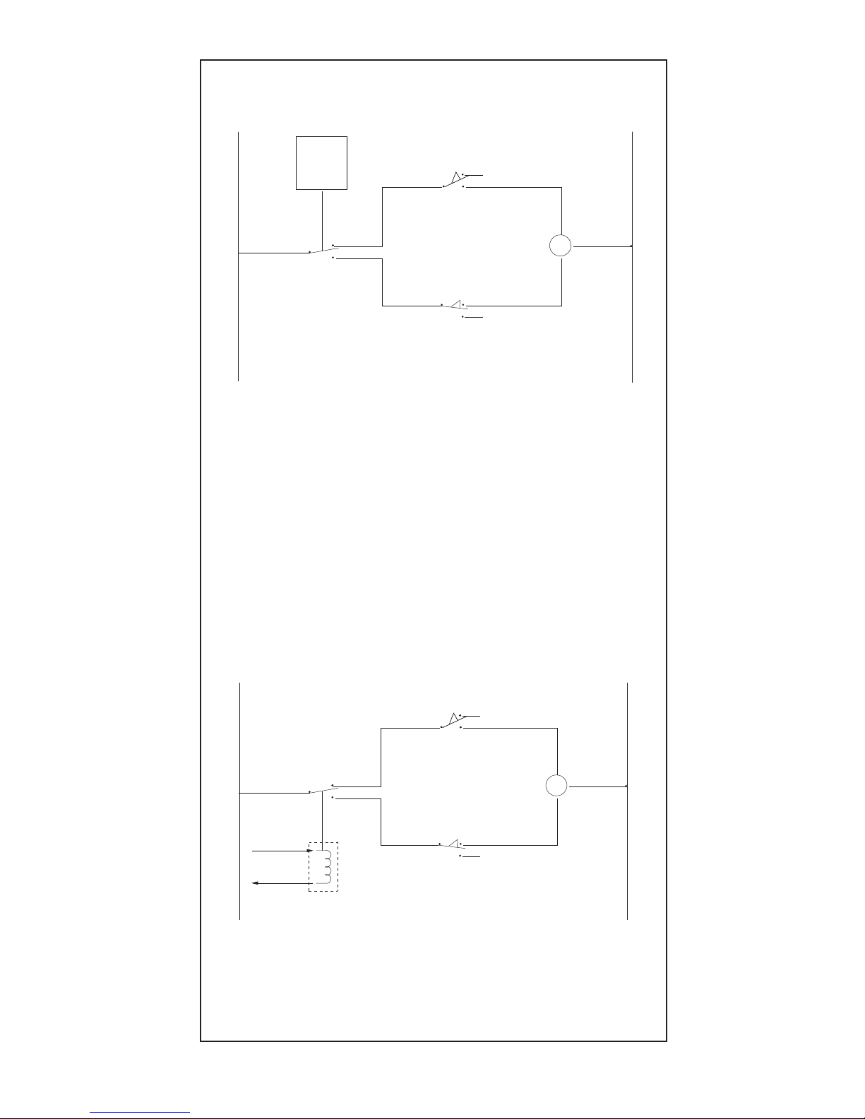
M
H N
N.O.
Upper Limit
Microswitch
N.C.
Lower Limit
Microswitch
6
Computer/Controller
Modular Basket Lift Simplified Schematic
To computer/controller
via interface board
Basket Lift
Relay
3
1 or 4
5
M
2-Pole
Mech
Timer
H N
N.O.
Upper Limit
Microswitch
N.C.
Lower Limit
Microswitch
4 or 6
3
1 or 5
Manual (Push-Button)
Modular Basket Lift Simplified Schematic
When the timer button is pushed, the lower circuit is activated. The basket lift lowers,
closing the normally open upper microswitch. The motor loses power when the basket
lift rod moves down and opens the lower, normally closed microswitch. When the timer
times-out, the upper circuit is activated. The basket lift rises, closing the lower
microswitch. When the rod clears the upper microswitch, it opens and power is again
cut to the motor. Pushing the timer button again restarts the cycle.
When the product button is pushed on the computer/controller, current flows through
a coil in the basket lift relay. The lower circuit is activated and the basket lift lowers,
closing the upper, normally open microswitch. The basket lift rod moves down,
opening the lower, normally closed microswitch and removing power from the motor.
When the computer/controller times-out, the relay coil loses current and the upper
circuit is activated. The basket lift rises, closing the lower microswitch. When the rod
opens the upper microswitch, power to the motor is lost again. Pushing the product
button again restarts the cycle.
1-22
Page 28
1.5.2 Interpretation of Analog Controller Lights
Power light ON, heat light cycling, trouble light OFF, and melt light ON:
• If the fryer oil temperature is below 180°F (82°C), the lights indicate that the unit is operating
normally.
• If the fryer oil temperature is above 180°F (82°C) and the heat light continues to cycle as if in the
melt cycle, this may indicate a defective probe circuit or low incoming 12 VAC to the controller.
Power light ON, heat light ON, trouble light OFF, and melt light OFF:
• If the fryer oil temperature is above 180°F (82°C) and below the setpoint temperature, the lights
indicate that the unit is operating normally.
• If the fryer oil temperature is above setpoint and the heat light remains lit, this may indicate a defective
probe circuit.
Power light ON, heat light OFF, trouble light ON, and melt light OFF:
• If the fryer oil temperature is below 410°F (210°C), the lights indicate one of the following:
a. The probe circuit is defective, or
b. There is a connection problem on pins 2 or 10 on the 15-pin wiring harness.
• If the fryer oil temperature is above 410°F (210°C), the lights indicate a “run-away” heating circuit.
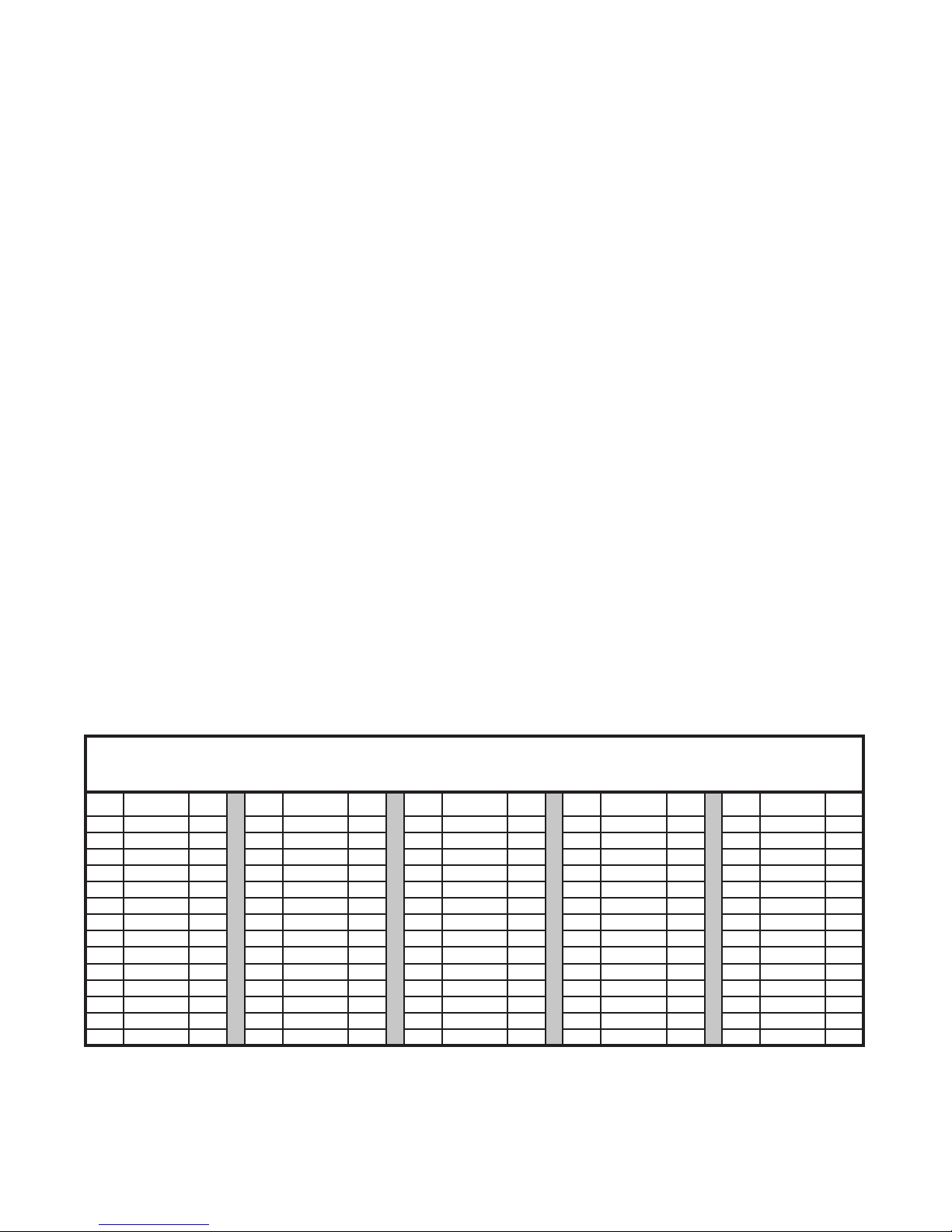
1.6 Probe Resistance Chart
Probe Resistance Chart
For use with 35- and 45-series fryers manufactured with Minco Thermistor probes only.
F OHMS C F OHMS C F OHMS C F OHMS C F OHMS C
60 1061 16 130 1206 54 200 1350 93 270 1493 132 340 1634 171
65 1070 18 135 1216 57 205 1361 96 275 1503 135 345 1644 174
70 1080 21 140 1226 60 210 1371 99 280 1514 138 350 1654 177
75 1091 24 145 1237 63 215 1381 102 285 1524 141 355 1664 179
80 1101 27 150 1247 66 220 1391 104 290 1534 143 360 1674 182
85 1112 29 155 1258 68 225 1402 107 295 1544 146 365 1684 185
90 1122 32 160 1268 71 230 1412 110 300 1554 149 370 1694 188
95 1133 35 165 1278 74 235 1422 113 305 1564 152 375 1704 191
100 1143 38 170 1289 77 240 1432 116 310 1574 154 380 1714 193
105 1154 41 175 1299 79 245 1442 118 315 1584 157 385 1724 196
110 1164 43 180 1309 82 250 1453 121 320 1594 160 390 1734 199
115 1174 46 185 1320 85 255 1463 124 325 1604 163 395 1744 202
120 1185 49 190 1330 88 260 1473 127 330 1614 166 400 1754 204
125 1195 52 195 1340 91 265 1483 129 335 1624 168 405 1764 207
1-23
Page 29

1.7 Troubleshooting Guides
The following are only guides. They are provided to assist the technician or service professional in the
isolation of failures in components and wiring on the fryer.
1.7.1 Troubleshooting the 24 VAC Circuit
Troubleshooting the 24 VAC Circuit: Analog Controller
Before troubleshooting, verify that the drain valve(s) is fully closed and move the power switch into the
ON position.
PROBLEM PROBABLE CAUSES
24 VAC not present at gas valve or the power switch. • Failed 24 volt transformer
Continuity across the power switch not equal to 0. • Failed power switch
Continuity across the thermostat not equal to 0. • Failed thermostat
• If 24 VAC is present at the gas valve, go to Troubleshooting the Gas Valve, Section 1.7.2.
Troubleshooting the 24 VAC Circuit: Electronic Ignition (Computer Controller)
Before troubleshooting, verify that the drain valve is fully closed, then turn on the controller.
PROBLEM PROBABLE CAUSES
No LEDs on the interface board are lit. • Failed 24 volt transformer
• Failed interface board
• Failed or open drain safety switch
• Failed wiring between components
24 volt LED on the interface board is lit, no others. • Failed interface board
• Failed or open drain safety switch
• Failed wiring between components
GV LED on the interface board is lit (with or without other LEDs). • Failed interface board
• Open high-limit thermostat
• Failed or open drain safety switch
• Failed wiring between interface board
and gas valve
• Failed gas valve
LED 3 is continually lit, but LED 2 and LED 4 are not lit. • Failed heat relay
• Failed interface board
LEDs 2, 3, and 4 are lit, but 24 VAC is not present at V1S (V1D and
V2D on dual-vat units).
LEDs 2, 3, and 4 are lit, and 24 VAC is present at V1S (V1D and
V2D on dual-vat units).
• Failed igition module
• Failed interface board
• Failed interface board
• If a failed ignition module is suspected, replace the questionable module with one known to be good to isolate the problem.
• If 24 VAC is present on pin 6 on J1, but the pilot will not light, go to Troubleshooting the Gas Valve, Section 1.7.2.
• If 24 VAC is present on pin 20 of the 20-pin terminal block, but not at the gas valve, go to Troubleshooting the Gas Valve,
Section 1.7.2.
1-24
Page 30

Troubleshooting the 24 VAC Circuit: Standing Pilot (Computer Controller)
Before troubleshooting, verify that the drain valve is fully closed, then turn on the controller.
PROBLEM PROBABLE CAUSES
No LEDs on the interface board are lit. • Failed 24 volt transformer
• Failed interface board
• Failed or open drain safety switch
• Failed wiring between components
24 volt LED on the interface board is lit, no others. • Failed interface board
• Failed or open drain safety switch
• Failed wiring between components
GV LED on the interface board is lit (with or without other LEDs). • Failed interface board
• Open high-limit thermostat
• Failed or open drain safety switch
• Failed wiring between interface board
and gas valve
• Failed gas valve
Continuity across drain safety switch(es) not equal to 0 • Failed or open drain safety switch.
24 VAC is not present at V1S (V1D and V2D on dual-vat units). • Failed interface board
• If 24 VAC is present all the way through to the high-limit, go to Troubleshooting the Gas Valve, Section 1.7.2.
1.7.2 Troubleshooting the Gas Valve
Before troubleshooting, verify that the gas main street valve is open and the fryer gasline cutoff valve is
open. Place the gas valve in the ON position.
PROBLEM PROBABLE CAUSES
Incoming gas pressure is too high or low. • Problem with gas supply
Pilot won’t remain lit, low millivolt output from thermopile. • Failed thermopile
Pilot won’t remain lit, good millivolt output from thermopile. • Failed gas valve
• Failed high-limit
• If 24 VAC is not present at the gas valve, go to Troubleshooting the 24 VAC Circuit, Section 1.7.1.
1.7.3 Troubleshooting the Thermostat
Check the calibration of the thermostat before troubleshooting, if possible.
PROBLEM PROBABLE CAUSES
The burner does not light when the thermostat is set to the maxi-
mum setting.
• Failed thermostat
• Failed wiring
• If 24 VAC is present at the gas valve, but the burner is not lighting, go to Troubleshooting the Gas Valve, Section 1.7.2.
1-25
Page 31

1.7.4 Troubleshooting the Temperature Probe
Follow these guidelines to troubleshoot the temperature probe:
1. While it is still in the frypot, inspect the probe body for damage. Inspect the leads for fraying, burning,
breaks, or kinks. If the probe is bent, dented, or cracked, or if the leads are damaged, replace the
probe.
2. Determine the temperature of the cooking oil using a thermometer or pyrometer placed at the tip of
the probe.
3. Disconnect the 15-pin wiring harness from the interface board. Measure the probe resistance using J2
pins 13 and 14.
4. Resistance should approximately equal the given probe resistance for the corresponding temperature
on the chart in Section 1.6, Page 1-23. If not, the probe has failed and must be replaced. Probes cannot
be calibrated.
5. If the resistance matches the corresponding temperature on the chart, measure the resistance through
J2 pin 13 and ground. Then, through J2 14 and ground. If the resistance of each pin is 5 megaohms
or greater, the probe is working correctly. If the resistance is less than 5 megaohms, it has failed and
must be replaced.
1-26
Page 32
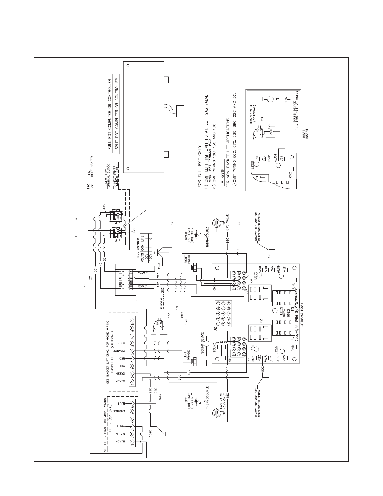
1.8 Wiring Diagrams
1.8.1 Standing Pilot
1-27
Page 33

1.8.2 Electronic Ignition
1-28
Page 34

1.8.3 Non-Computer Controlled Fryer
1-29
Page 35
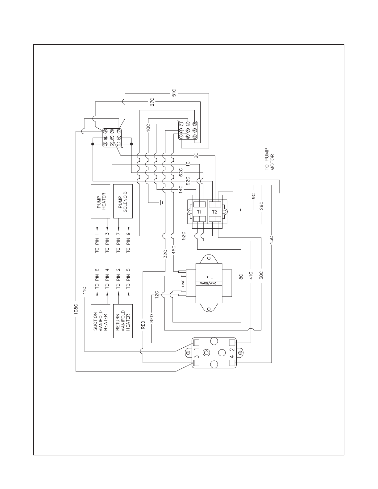
1.8.4 Filter Box
1-30
Page 36
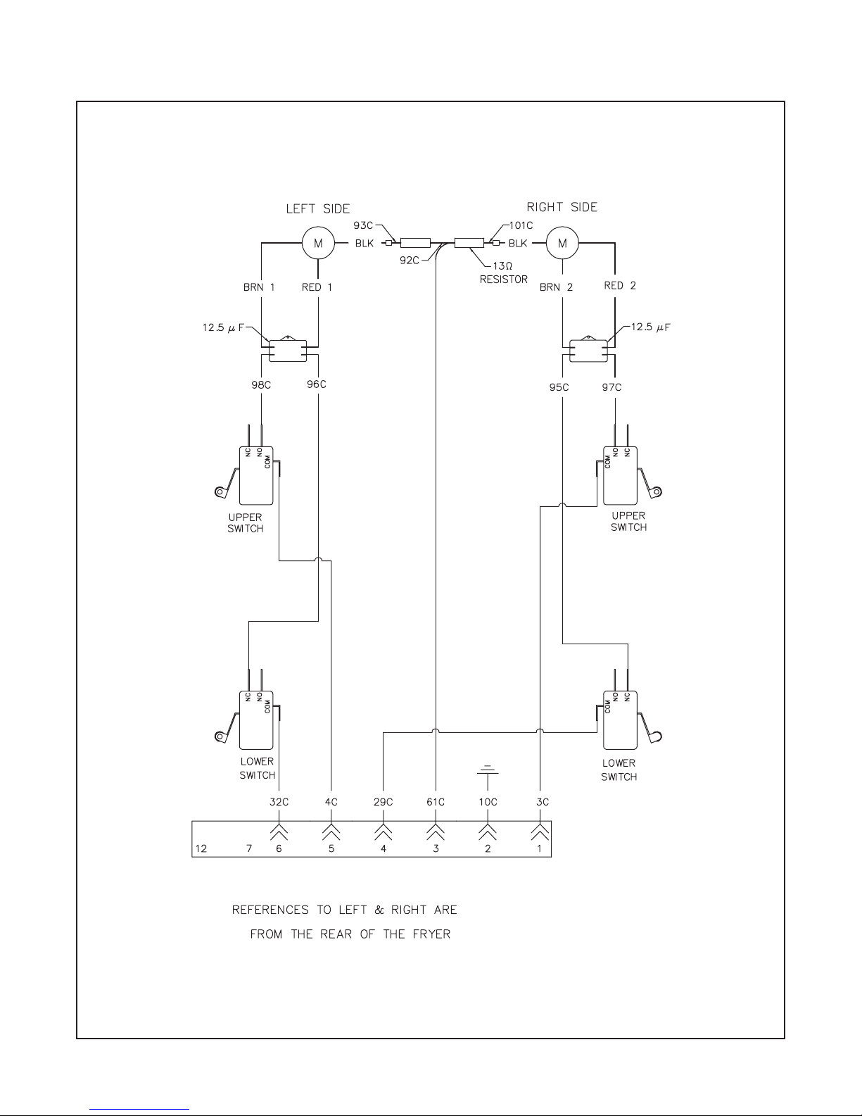
1.8.5 Modular Basket Lift 100/120V
1-31
Page 37

1.8.6 Modular Basket Lift 208/250V
1
12 - - - - - 7
2
3
4
5
6
1-32
Page 38
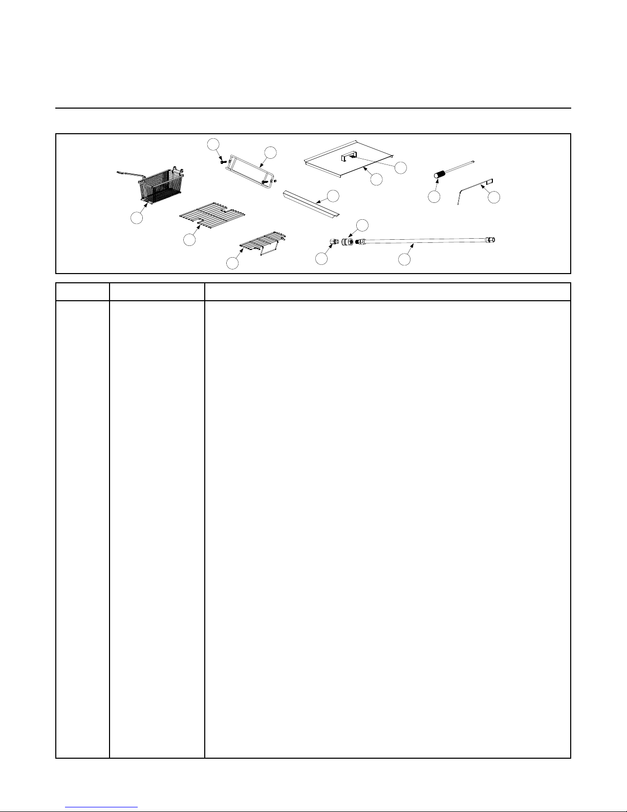
PERFORMANCE PRO SERIES GAS FRYERS MODELS 35 & 45
1
2
3
6
5
4
7
8
9
10
11
12
13
2.1 Accessories
ITEM PART # COMPONENT
1 810-2793 Wireform Basket Hanger
* 106-2186 Basket Hanger, Burger King
* 823-4447 Basket Hanger, Buffalo Wild Wings® and Jack in the Box
2 809-0171
* 803-0099 Full Basket
3 803-0271 Twin Basket
* 803-0198 Basket, 1.5 Fryer
4 803-0132 Wire Basket Support Rack, Full-vat (MJ 45)
5 803-0133 Wire Basket Support Rack, Dual-vat
* 803-0032 Wire Basket Support Rack, without Notches (MJ 35)
* 803-0136 Basket Support Screen (MJ 45)
* 803-0037 Basket Support Screen (MJ 35)
6 810-0088 Flexible Gas Line, 1-36
* 810-0084 Flexible Gas Line, ¾-48
7 810-0073 Quick Disconnect Fitting, 1” Female
8 810-0074 Quick Disconnect Fitting, 1” Male
* 803-0188 Sediment Tray, Full-vat (MJ 35)
* 803-0103 Sediment Tray, Full-vat, (MJ 45)
* 803-0107 Sediment Tray, Dual-vat, Left (MJ 45)
* 803-0108 Sediment Tray, Dual-vat, Right (MJ 45)
* 823-3660 Crumb Scoop
9 910-7443 Top Connecting Strip, Frypot
* 910-6650 Channel, Top Connecting Strip
* 823-1885 Top Connecting Strip and Channel, Burger King
* 210-9291 Top Connecting Strip, Fryer-to-Fryer
* 910-4617 Top Connecting Strip, Fryer-to-Spreader
10 806-5518 Cover, Frypot or Holding Station
11 826-0993SP Handle Kit, Frypot Cover
* 826-1351 Nut Retainer, ¼-20 Nutsert (pkg. of 10)
12 803-0197 Fryer Friend (Clean-out Rod), 27”
13 803-0209 Brush, Fryer
* OPT32686 Foodwarmer (with scoop pan)
* 806-6988 Foodwarmer Kit
* 106-4786 Spreader Storage Pan
* 910-3557
* 826-1017
* KIT3647
* Not illustrated.
Basket Hanger Screw (basket hanger spacer, 809-0921)
Flue Deector (See Section 2.6 for more information and associated items.)
Screw Kit, Flue Deector (See Section 2.6 for more information and associated items.)
Applebee’s® Heat Lamp (available as OPT33030)
CHAPTER 2: PARTS LIST
®
2-1
®
Page 39

2.2 Basket Lift and Associated Parts
1
3
2
5
4
26
7
9
10
12
11
13
8
11
25
14
15
13
14
15
15
15
16
23
24
100-120V Configuration
208-250V Configuration
17
18
19
20
6
25
20
25
22
(After 10/02)
Before (11/02)
27
NOTES:
1. Assemblies 106-1807SP (100-120V) and 106-1810 (230/240/250V) do not
include Items 1, 9, 17, 2, or 3. These items must be ordered separately.
2. For 100-120V units, each individual resistor (807-2661) may be replaced
or the entire resistor assembly (806-8530SP) may be replaced.
3. For 208-250V units, the entire resistor assembly (106-2771 or 806-9185)
must be replaced.
4. Wiring has been omitted for clarity.
2-2
Page 40

ITEM PART # COMPONENT
1 910-4776 Enclosure, Stainless Steel
* 900-4776 Enclosure, Cold-rolled Steel
* 826-1991 Kit, Cold-rolled Steel Enclosure (with 12 screws)
2 823-06931 Basket Lift Arm, Left
3 823-06932 Basket Lift Arm, Right
4 901-8499 Chassis, Left
5 902-8499 Chassis, Right
6 200-2942 Mount, Basket Lift
7 809-0082 Truarc Retaining Ring, ¾”
8 826-1361 Screw, 8-32 x 1” Slotted Truss Head (pkg. of 25)
9 809-0127 Screw, ¼-20 x ½” Slotted Round Head
10 809-0186 Lock Washer with External Teeth, #8
11 826-1366 Nut, 4-40 Hex Keps with External Tooth (pkg. of 25)
12 809-0247 Nut, 8-32 Hex Keps
13 826-1359 Screw, 4-40 x ¾” Slotted Round Head (pkg. of 25)
14 826-1371 Screw, #8 x ½” Hex Head Drill Point (pkg. of 25)
15 826-1374 Screw, #10 x ½” Hex Head (pkg. of 25)
16 809-0503 Screw, 8-32 x ½” Hex Head
17 810-0172 Plug, Stainless Steel, ⅝” Hole
18 810-1012 Toothed Rod, Basket Lift
19 812-0442 Insulation, Microswitch
20 813-0035 Bushing, Bronze, .640” ID
21 816-0033 Ty Wrap, Screw Mount
22 900-5529 Gusset, Basket Lift Motor
23 807-2513 Capacitor, Motor
24 807-2572 Microswitch
25 Resistor Assembly
806-8530SP 100-120V
106-2771 208-250V
26 806-5964SP Gear Motor Assembly
27 806-9257SP Roller Guide/Bracket Assembly
Basket Lift Assemblies
* 106-1807SP 100-120V (without relay)
* 106-1810SP 208-250V
* KIT6421 Complete 120V Basket Lift Assembly for FPP35/45
* KIT7193 Complete 230V Basket Lift Assembly for FPP35/45
* KIT7413 Complete 230V Basket Lift Assembly for PMJ35
* Not illustrated.
** Diagrams on Pages 1-22, 1-31, 1-32 in Chapter 1.
2-3
Page 41

1
7
8
10
13
23
3
4
6
5
2
9
11
14
15
16
17
18
19
22
21
24
20
12
2.3 Cabinetry
2.3.1 FPP/FMP Model Cabinetry
Front of fryer.
Rear of fryer.
Four station fryer shown.
2-4
Page 42

ITEM PART # COMPONENT
Cabinet Assemblies (see Section 2.3.3)
106-3783
106-4016
106-4017
106-4018
Two Station Fryer, Stainless (106-4031, Cold Rolled Steel)
Three Station Fryer, Stainless (106-4032, Cold Rolled Steel)
Four Station Fryer, Stainless (106-4033, Cold Rolled Steel)
Five Station Fryer, Stainless (106-4034, Cold Rolled Steel)
106-4525 Applebee’s® Dump Station
1
Base Assemblies
106-3785 Two Station Fryer
106-4019 Three Station Fryer
106-4020 Four Station Fryer
106-4021 Five Station Fryer
2
Brace, Top Cabinet
900-7730 Two Station Fryer
900-9430 Three Station Fryer
900-9318 Four Station Fryer
200-5474 Five Station Fryer
*
Back Panels, Upper (Use with cabinet assemblies.)
200-6901 Use with 106-3783, 106-4017, 106-4018, 106-4031, 106-4033, 106-4034.
200-6906 Use with 106-4016, 106-4018, 106-4032, 106-4034.
210-6608 Use with 106-3783, 106-4017, 106-4018.
210-6895 Use with 106-4016, 106-4018.
Back Panels, Lower
200-6905 Use with 106-3783, 106-4017, 106-4018, 106-4031, 106-4033, 106-4034.
200-6908 Use with 106-4016, 106-4018, 106-4032, 106-4034.
210-6897 Use with 106-4016, 106-4018.
210-6874 Use with 106-4034, 106-4032, 106-4016, 106-4018.
200-8567
3
Use with 106-4525 (Applebee’s® Dump Station).
Side, Left Cabinet
211-6893 Side, Left Cabinet, Stainless Steel
211-6933 Side, Left Cabinet, Stainless Steel (with hole)
201-6917 Side, Left Cabinet, Cold Rolled Steel
201-6934 Side, Left Cabinet, Cold Rolled Steel (with hole)
4
Side, Right Cabinet
212-6893 Side, Right Cabinet, Stainless Steel
212-6933 Side, Right Cabinet, Stainless Steel (with hole)
202-6917 Side, Right Cabinet, Cold Rolled Steel
202-6934 Side, Right Cabinet, Cold Rolled Steel (with hole)
Other Components
* 200-6908 Back, Lower Cabinet, Aluminized (three and ve station fryers)
* 210-6897 Back, Lower Cabinet, Stainless Steel (three and ve station fryers)
5 200-2235 Bracket, Component Box
6 200-1953 Brace, Front Cabinet
7 200-6057 Brace, Cabinet Cross
8 200-6062 Support, Upper Rear Cabinet
9 200-6310 Support, Rear Cabinet Rail
10 200-6346 Gusset, Rear Cabinet
11 200-6486 Brace, Front Cross
12 200-6892 Post, Front Door Long
13 200-6894 Post, Rear Cabinet Long
14 200-6911 Post, Front Cabinet Long
15 826-1389 Screw, ¼-20 x ¾” Hex Head (pkg. of 10)
* Not illustrated.
FPP/FMP Model Cabinetry continued on next page...
** Four station fryers use two backs made for two station fryers. Five station fryers use two backs: a three station fryer back and a two
station fryer back.
2-5
Page 43
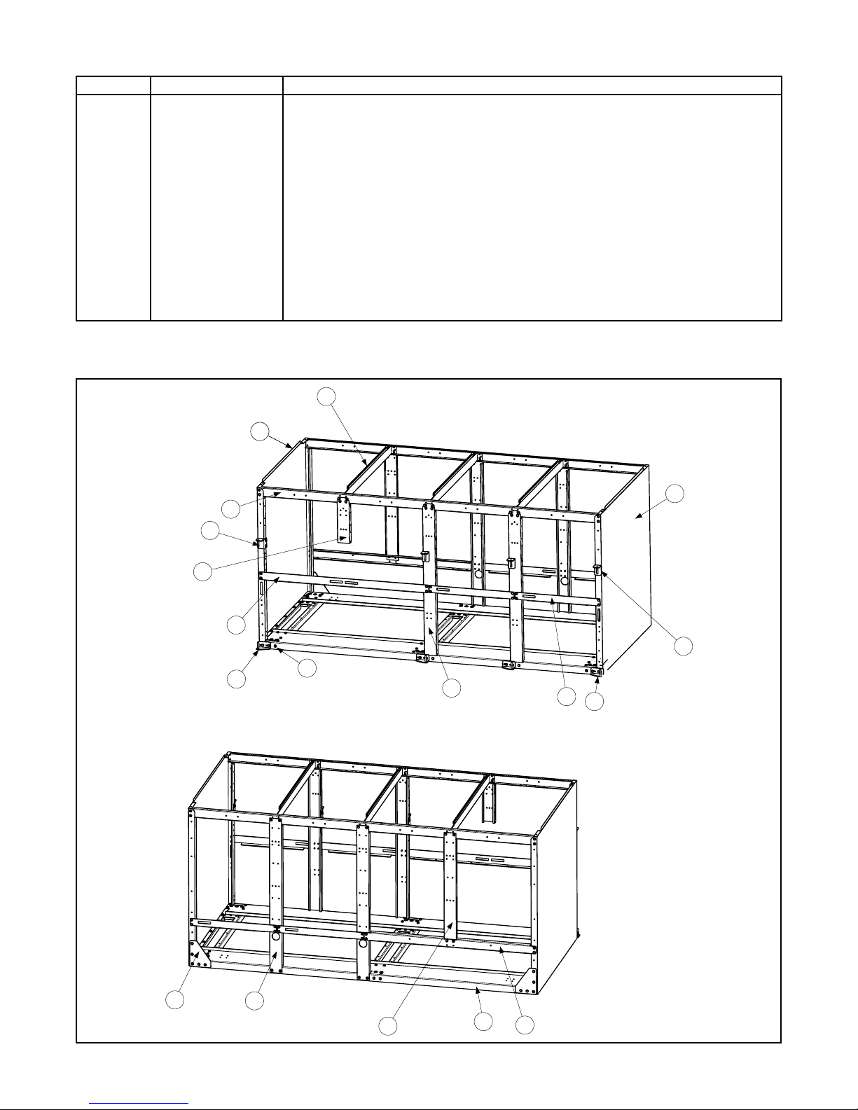
1
2
3
6
5
4
7
8
10
11
12
13
14
15
16
17
18
9
ITEM PART # COMPONENT
16 826-1374 Screw, #10 x ½” Washer Hex Head (pkg. of 25)
17 809-0417 Nut, Flange
18 823-4727 Hinge Assembly, Left Upper
19 823-4728 Hinge Assembly, Right Upper
20 823-4745 Hinge Assembly, Left Lower
21 823-4746 Hinge Assembly, Right Lower
22 823-4735 Rail Assembly, Left
23 823-4736 Rail Assembly, Right
* 200-6935 Stop, Filter Rail
24 900-7326 Divider
* KIT0293 Joiner Kit, Applesbee’s® Dump Station
* OPT33515 Scoop Pan/Rim/Cover (FMP 45)
* Not illustrated.
2.3.2 PMJ (Non-lter) Model Cabinetry
Front of fryer.
Rear of fryer.
Four station fryer shown.
2-6
Page 44

ITEM PART # COMPONENT
Cabinet Assemblies
106-4028
106-4036
106-4037
106-4038
106-4039
Single Station Fryer, Stainless (106-4030, Cold Rolled Steel)
Two Station Fryer, Stainless (106-4051, Cold Rolled Steel)
Three Station Fryer, Stainless (106-4052, Cold Rolled Steel)
Four Station Fryer, Stainless (106-4053, Cold Rolled Steel)
Five Station Fryer, Stainless (106-4054, Cold Rolled Steel)
106-4525 Applebee’s® Dump Station
1
Base Assemblies
106-5440 Single Station Fryer
106-4040 Two Station Fryer
106-4041 Three Station Fryer
106-4042 Four Station Fryer
106-4043 Five Station Fryer
*
Back Panels, Single
200-6903 Use with 106-4030, 106-4028.
200-6904 Use with 106-4030, 106-4028.
210-6817 Use with 106-4028.
210-6818 Use with 106-4028.
200-5867 Use with 105-4525 (Applebee’s®).
*
Back Panels, Upper (Use with cabinet assemblies.)
200-6901 Use with 106-4036, 106-4038, 106-4039, 106-4051, 106-4053.
200-6902 Use with 106-4036, 106-4051, 106-4053.
200-6906 Use with 106-4037, 106-4039, 106-4052.
200-6907 Use with 106-4052, 106-4037.
210-6608 Use with 106-4036. 106-4038. 106-4039.
210-6895 Use with 106-4037, 106-4039.
210-6896 Use with 106-4037.
210-6650 Use with 106-4036, 106-4038.
*
Back Panels, Lower (Use with cabinet assemblies.)
200-6905 Use with 106-4036, 106-4038, 106-4039, 106-4051, 106-4053.
200-6908 Use with 106-4037, 106-4039, 106-4052.
210-6874 Use with 106-4037, 106-4039, 106-4052.
210-6897 Use with 106-4037, 106-4039.
2
Brace, Top Cabinet
900-4813 Single Station Fryer
900-7730 Two Station Fryer
900-9430 Three Station Fryer
900-9318 Four Station Fryer
200-5474 Five Station Fryer
3
Side, Left Cabinet
211-6893 Side, Left Cabinet, Stainless Steel
211-6933 Side, Left Cabinet, Stainless Steel (with hole)
201-6917 Side, Left Cabinet, Cold Rolled Steel
201-6934 Side, Left Cabinet, Cold Rolled Steel (with hole)
4
Side, Right Cabinet
212-6893 Side, Right Cabinet, Stainless Steel
212-6933 Side, Right Cabinet, Stainless Steel (with hole)
202-6917 Side, Right Cabinet, Cold Rolled Steel
202-6934 Side, Right Cabinet, Cold Rolled Steel (with hole)
* Not illustrated.
PMJ (Non-lter) Model Cabinetry continued on next page...
** Four station fryers use two backs made for two station fryers. Five station fryers use two backs, a three station fryer back with a two
station fryer back.
2-7
Page 45

ITEM PART # COMPONENT
Other Components
* 200-6908 Back, Lower Cabinet, Aluminized (three and ve station fryers)
* 210-6897 Back, Lower Cabinet, Stainless Steel (three and ve station fryers)
5 200-2235 Bracket, Component Box
6 200-1953 Brace, Front Cabinet
7 200-6057 Brace, Cabinet Cross
8 200-6062 Support, Cabinet upper Rear
9 200-6346 Gusset, Rear Cabinet
10 200-6486 Brace, Front Cross
11 200-6894 Post, Rear Cabinet Long
12 200-6911 Post, Front Cabinet Long
13 826-1374 Screw, #10 x ½” Washer Hex Head (pkg. of 25)
14 823-4727 Hinge Assembly, Left Upper
15 823-4728 Hinge Assembly, Right Upper
16 823-4745
Hinge Assembly, Left Lower (823-4713 on single fryers)
17 823-4746 Hinge Assembly, Right Lower
18 900-7326 Divider
* KIT0293 Joiner Kit, Applesbee’s® Dump Station
* Not illustrated.
2-8
Page 46

2.4 Casters, Legs, and Associated Hardware
1
3
4
5
6
2
7
ITEM PART # COMPONENT
1
806-3811 Legs (pkg. of 4)
806-5043 Leg, Individual
2 826-1095 Anchor Strap Kit
3 810-0357 Caster, 5” Swivel with Brake
4 810-0356 Caster, 5” Swivel without Brake (with hardware, 826-1117)
5 810-0378 Caster, 5” Rigid
6 810-0651 Caster, 3” with Brake, Filter Cabinet (with hardware, 826-1130)
* 810-0750 Caster, 5” Rigid (PMJ units)
7 826-0900 Chain Restraint Kit
* 823-1113 Fastener Kit (one per caster or leg)
* Not illustrated.
Legs
Casters
2-9
Page 47

2.5 Component Boxes
Full-vat Component Box Assembly
(106-4117, 106-4118, 106-4119, 106-4120)
Dual-vat Component Box Assembly
(106-4121, 106-4122, 106-4123, 106-4124)
Component Box Cover
(200-6956)
1
2
3
6
5
4
7
8
9
10
11
12
13
1
2
6
5
4
7
8
9
10
2.5.1 Component Boxes without Melt Cycle
Illustrations may differ slightly from actual boxes depending upon the conguration of the fryer.
2-10
Page 48

ITEM PART # COMPONENT
Complete Box Assemblies
100-120V (Domestic)
106-4117 Full-vat
106-4121 Dual-vat
120V (Domestic)
106-4118 Full-vat
106-4122 Dual-vat
208-240V (Domestic)
106-4119 Full-vat
106-4123 Dual-vat
208-250V (Export)
106-4120 Full-vat
106-4124 Dual-vat
Components
1 200-6970 Component Box
2 200-6855 Bracket, Component Box Gap
3 200-6956 Cover, Component Box Hole
4 810-0045 Bushing, .875”
5 810-1164 Terminal Block, 1 Plc. Screwless Terminal
6 810-1168 Terminal Block, Screwless End
7 816-0217 Insulating Paper
Wiring
* WIR0162 Component Shield Wiring (FV, DV)
* WIR0349 Microswitch Wiring (DV)
* WIR0350 Microswitch Wiring (DV)
8 Transformers
807-2176 100-120V/12V & 24V
807-0855 120V/12V
807-0800 120V/24V
807-0680 208-240V/24V
807-1999 208-250V/12V & 24V
9 826-1365 Screw, 6-32 x ⅜ Trussed Slotted Head (pkg. of 25)
10 826-1359 Screw, 4-40 x ¾ Pan Slotted Head (pkg. of 25)
11 809-0360 Screw, #8 x ⅜ Type B Hex Washer
12 826-1366 Nut, 4-40 Hex Keps with External Tooth (pkg. of 25)
13 809-0250 Nut, 6-32 Hex Keps
* Not illustrated.
** See Section 2.17 for thermostats, timers, and associated knobs.
2-11
Page 49

2.5.2 Component Boxes with Melt Cycle
Component Box with Mechanical Timer
(106-4134)
Full-vat Component Box Assembly
(106-4125, 106-4126, 106-4127, 106-4128)
Dual-vat Component Box Assembly
(106-4129, 106-4130, 106-4131, 106-4132)
1
2
3
6
5
7
4
9
10
11
1
2
11
9
6
3
5
7
8
10
1
2
6
9
10
3
5
7
8
11
Illustrations may differ slightly from actual boxes depending upon the conguration of the fryer.
2-12
Page 50

ITEM PART # COMPONENT
Complete Box Assemblies
100-120V (Domestic)
106-4125 Full-vat with Melt Cycle
106-4129 Dual-vat with Melt Cycle
120V (Domestic)
106-4126 Full-vat with Melt Cycle
106-4130 Dual-vat with Melt Cycle
208-240V (Domestic)
106-4127 Full-vat with Melt Cycle
106-4131 Dual-vat with Melt Cycle
208-250V (Export)
106-4128 Full-vat with Melt Cycle
106-4132 Dual-vat with Melt Cycle
106-4134 With Mechanical Melt Cycle Timer (CE)
Components
1 200-6970 Component Box
2 200-6855 Bracket, Component Box Gap
* 200-6956
Cover, Component Box Hole (see illustration on Page 2-10)
3 810-0045 Bushing, .875”
4 826-1546 Melt Cycle Kit with Mechanical Timer
5 810-1164 Terminal Block, 1 Plc. Screwless Terminal
6 810-1168 Terminal Block, Screwless End
7 816-0217 Insulating Paper
8 806-9613 Board, Melt Cycle Timer
Wiring
* WIR0161 Component Shield (with Melt Cycle) Wiring (DV)
* WIR0164 Component Shield (with Melt Cycle) Wiring (FV, 240V and below)
* WIR0165 Component Shield (Std.) Wiring (FV, 208-250 Export only)
* WIR0148 Component Shield (with Mechanical Timer) Wiring
9 Transformers
807-2176 100-120V/12V & 24V
807-0855 120V/12V
807-0800 120V/24V
807-0680 208-240V/24V
807-1999 208-250V/12V & 24V
10 826-1365 Screw, 6-32 x ⅜ Trussed Slotted Head (pkg. of 25)
11 826-1359 Screw, 4-40 x ¾ Pan Slotted Head (pkg. of 25)
* Not illustrated.
2-13
Page 51
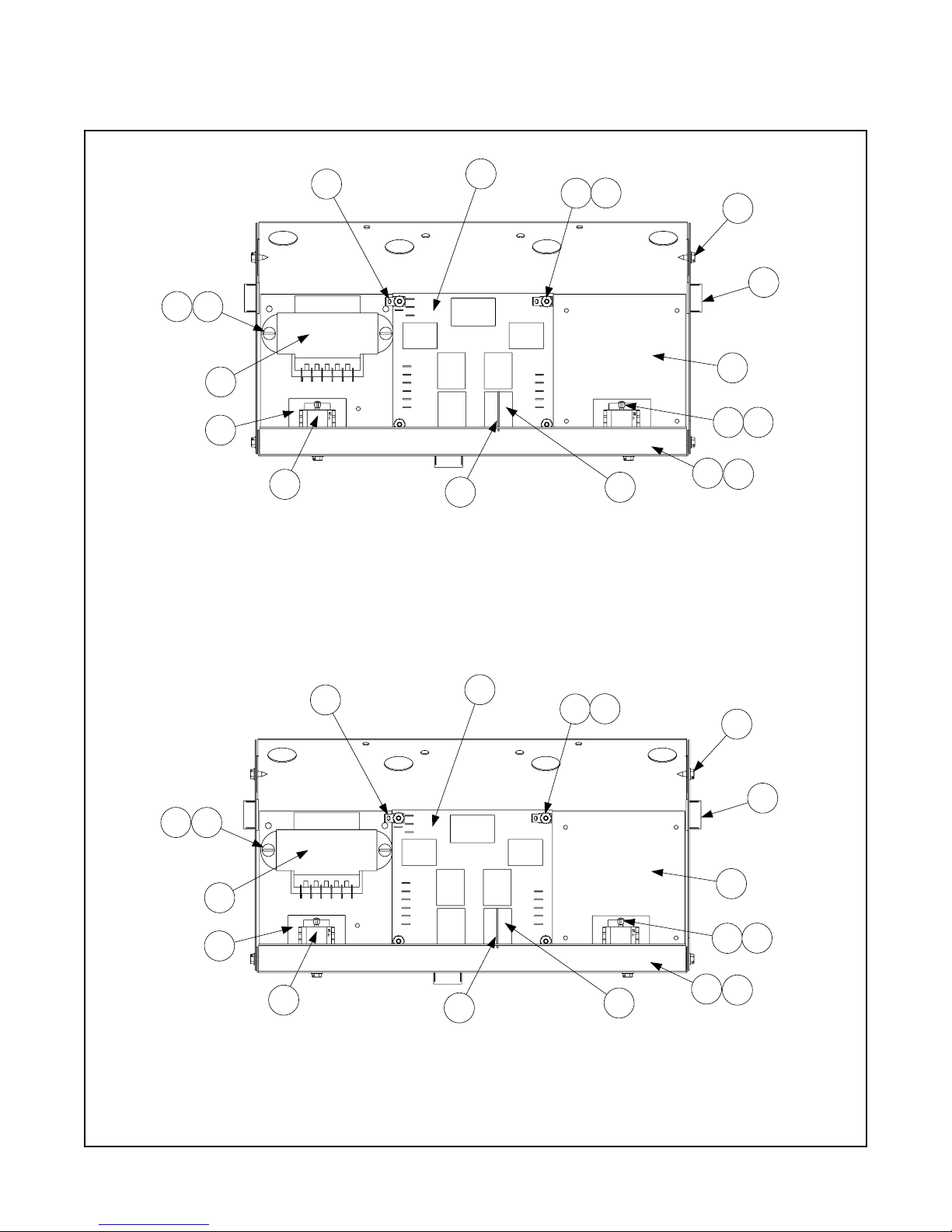
2.5.3 Component Boxes with Standing Pilot
Dual-vat Component Box Assembly
(106-4111, 106-4112, 106-4113, 106-4114)
1
3
2
17
4
18
16
14
10
13
12
7
8
9
11
15
5
6
Full-vat Component Box Assembly
(106-4084, 106-4085, 106-4086, 106-4087)
1
3
2
17
4
18
16
14
10
13
12
7
8
9
11
15
5
6
Illustrations may differ slightly from actual boxes depending upon the conguration of the fryer.
2-14
Page 52
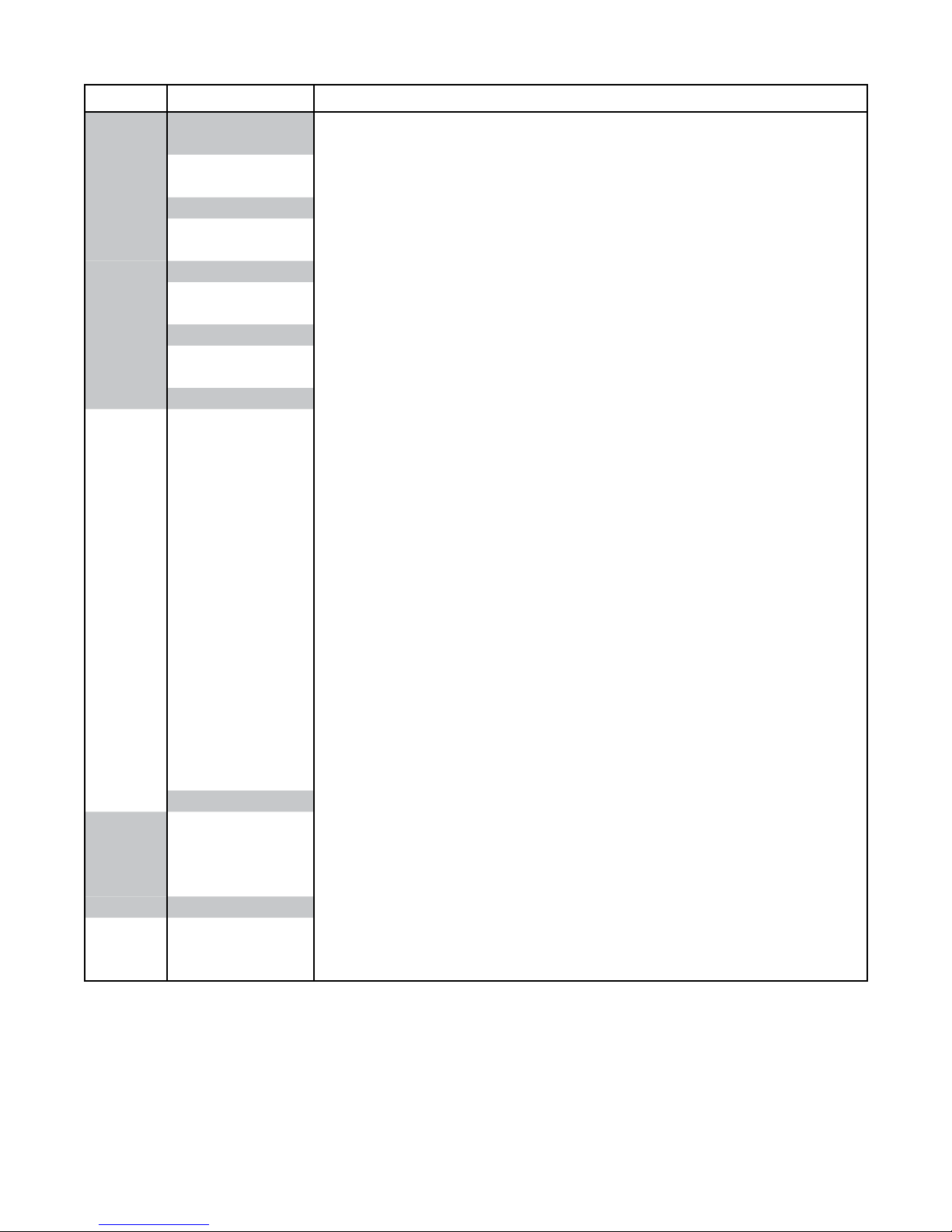
ITEM PART # COMPONENT
Complete Box Assemblies
100-120V (Domestic)
106-4084 Full-vat (Shield Assembly 106-4096)
106-4111 Dual-vat (Shield Assembly 106-4091)
120V (Domestic)
106-4085 Full-vat (Shield Assembly 106-4097)
106-4112 Dual-vat (Shield Assembly 106-4092)
208-240V (Domestic)
106-4086 Full-vat (Shield Assembly 106-4098)
106-4113 Dual-vat (Shield Assembly 106-4093)
208-250V (Export)
106-4087 Full-vat (Shield Assembly 106-4099)
106-4114 Dual-vat (Shield Assembly 106-4094)
Components
1 106-4088 Component Stud, Shield
2 826-1337 Tab, Terminal (pkg. of 5)
3 806-4549 PC Board Assembly
4 809-0349 Spacer, Interface Board
5 200-6855 Bracket, Component Box Gap
6 200-6956
Cover, Component Box Hole (see illustration on Page 2-10)
7 807-0833 Relay, Latch
* 807-0834 Relay, Basket Lift
8 810-2243 Spring, Relay Hold Down
9 810-1164 Terminal Block, 1 Plc. Screwless
10 816-0217 Insulating Paper
11 810-0045 Bushing
12 809-0247 Nut, 8-32 Hex Keps
13 809-0102 Screw, 8-32 x ⅜ Trussed Slotted Head
14 826-1359 Screw, 4-40 x ¾ Pan Slotted Head (pkg. of 25)
15 809-0360 Screw, #8 x ⅜ Type B Hex Washer
16 826-1366 Nut, 4-40 Hex Keps with External Tooth (pkg. of 25)
17 809-0250 Nut, 6-32 Hex Keps
18 Transformers
807-2176 100-120V/12V & 24V
807-0800 120V/24V
807-0680 208-240V/12V & 24V
807-1999 208-250V/12V & 24V
Wiring
* WIR0163 Component Shield Wiring (FV)
* WIR0160 Component Shield Wiring (DV)
* WIR0329 Component Shield Drainswitch Wiring (DV/FV)
* Not illustrated.
2-15
Page 53

2.5.4 Component Boxes with Electronic Ignition
5
4
12
17
1
2
13
11
22
21
19
10
9
18
16
Australian/250V Full-vat Component Box Assembly
(106-4066)
6
14
23
1
2
3
7
8
9
10
13
15
16
18
19
20
5
21
11
22
Full-vat Component Box Assembly
(106-4064, 106-4065)
14
23
6
Illustrations may differ slightly from actual shields depending upon the conguration of the fryer.
2-16
Page 54

ITEM PART # COMPONENT
Complete Box Assemblies
106-4064
106-4065
106-4066
Full-vat, 120V (Domestic; Shield Assembly 106-4075)
Full-vat, 208-240V (Domestic; Shield Assembly 106-4076)
Full-vat, 208-250V (Export; Shield Assembly 106-4077)
Components
1 106-4088 Component Stud
2 826-1337 Tab, Terminal (pkg. of 5)
3 807-4037 Ignition Module, Domestic (240V and below)
4 807-2971 Ignition Module, Export (208-250V)
5 806-5857 PC Board Assembly
6 810-0045 Bushing, .875
7 807-0670 Relay, 24V
8 200-7176 Bracket, Relay
9 810-1164 Terminal Block, 1 Plc. Screwless
10 816-0217 Insulating Paper
* WIR0258 Wiring, Component Shield
11 809-0349 Spacer, Interface Board
12 826-1346 Spacer, Ignition Module (pkg. of 10)
13 Transformers
807-2176 100-120V/12V & 24V
807-1999 208-240V/24V, 208-250V/12V & 24V
14 200-6855 Bracket, Component Box Gap
15 809-0328 Screw, 4-40 x ¼ Pan Slotted Head
16 809-0247 Nut, 8-32 Hex Keps
17 809-0164 Screw, #8 x 1 Hex Washer Slotted Head
18 809-0102 Screw, 8-32 x ⅜ Trussed Slotted Head
19 826-1359 Screw, 4-40 x ¾ Pan Slotted Head (pkg. of 25)
20 809-0360 Screw, #8 x ⅜ Type B Hex Washer
21 826-1366 Nut, 4-40 Hex Keps with External Tooth (pkg. of 25)
22 809-0250 Nut, 6-32 Hex Keps
23 200-6956
Cover, Component Box Hole (see illustration on Page 2-10)
* 806-5879SP Cable Assembly, Ignition Module
* 807-3483
Cable, Ignition (used with MJ45 ignition cable kit, 826-1721)
* 806-5830 Cable Assembly, Ignition
* 807-1928 Flame Sensor Electrode
* 807-3484 Connector, Rajah
* Not illustrated.
2-17
Page 55

2.6 Control Panel Assemblies, Flue Caps, and Related Items
3 2
1
24
25
4
5
20
22
21
27
18
26
23
6
11
16
7
12
17
8
13
18
9
14
19
10
15
20
32
32
33
34
28
29
30
31
35
2-18
Page 56

ITEM PART # COMPONENT
Control Panel Assemblies
1 106-4062 Single Station Fryer
2 106-3902 Two Station Fryer
3 106-3903 Three Station Fryer
4 106-3904 Four Station Fryer
5 106-3905 Five Station Fryer
* 106-4535 Applebee’s® Control Panel
Flue Caps
MJ 45
6 210-6812 Single Station Fryer
7 106-4012 Two Station Fryer
8 106-4013 Three Station Fryer
9 106-4014 Four Station Fryer
10 106-4015 Five Station Fryer
MJ 35
11 210-6811 Single Station Fryer
12 106-4008 Two Station Fryer
13 106-4009 Three Station Fryer
14 106-4010 Four Station Fryer
15 106-4011 Five Station Fryer
Burger King
16 106-4184
17 106-4185
18 106-4186
19 106-4187
* 824-1440 Applebee’s® Dump Station Flue Cap
20 910-3557
* 910-3207
* 900-3933 Heat Shield, Flue
* 826-1017 Screw Kit, Flue Deector
21 900-4253 Retaining Strip, Flue Cap
22 200-6584 Support, Flue Cap
Top Cap
23 824-1409 Single Station Fryer
24 824-1410 Two Station Fryer
25 823-4940 Three Station Fryer
26 823-4941 Four Station Fryer
27 823-4942 Five Station Fryer
* 823-4990 Applebee’s® Top Cap
Control Panel Assembly with Thermostat Access Door (MJ 35)
28 106-4050 Complete, with Toggle Switch
29 106-4049
Thermostat Access Door (MJ 35)
30 106-4386SP Toggle Switch Assembly
31 824-1394 Switch Guard
32 210-6930 Door Panel
33 210-8289 Frame, with Toggle
34 210-6832 Frame, without Toggle
* 106-4235 Control Panel, MV with Mechanical Timer (FPP)
35 210-6946 Control Panel, with holes (PMJ)
Two Station Fryer (with buttons, 106-4188)
Three Station Fryer (with buttons, 106-4189)
Four Station Fryer (with buttons, 106-4190)
Five Station Fryer (with buttons, 106-4191)
Deector, Flue (2 holes)
Deector, Flue (3 holes)
Complete, without Toggle Switch (see also 106-4591)
* Not illustrated.
2-19
Page 57
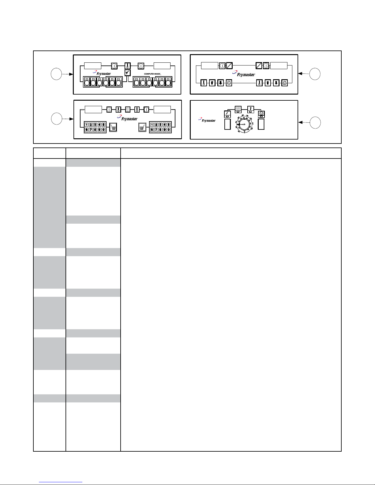
2.7 Controller Assemblies
1
2
3
4
C
F
C
F
L
1
2
3 4
5
6
7
8
9
0
R
SOLID STATE
ITEM PART # COMPONENT
1
106-4162 Full-vat
106-4164 Full-vat (CE)
106-4163 Dual-vat
106-4165 Dual-vat (CE)
106-1218 On-hood Remote Computer (FV, MJ 45)
106-1230 In-hood Remote Computer (FV, MJ 45)
106-4562
106-4561
106-4560
2
106-4170 Full-vat
106-4172 Full-vat (CE)
106-4171 Dual-vat
106-4173 Dual-vat (CE)
3
106-4174 Full-vat
106-4176 Full-vat (CE)
106-4175 Dual-vat
106-4177 Dual-vat (CE)
4
106-3375 Dual-vat
106-3369
* 210-5046 Single Station Fryer
* 210-5819 Two Station Fryer
* 210-6698 Three Station Fryer
* 210-6960 Single Station Fryer
* 210-6961 Two Station Fryer
* 210-6962 Three Station Fryer
* 210-6766 Applebee’s® Spreader
* 210-7002
* 806-3660 Sound Device
* Not illustrated.
Computer Magic III.5
Buffalo Wild Wings® Computer
Red (overlay, 807-4098)
Green (overlay, 807-4097)
Blue (overlay, 807-4096)
Basket Lift Timer
Digital Controller
Solid State (Analog Controller)
Full-vat (overlay, 807-0847)
Controller Bezel
Computer
No Computer
Blank Bezel (Applebee’s® spreader, 210-8578)
2-20
Page 58
WIRING ASSEMBLIES, HARNESSES, AND REMOTE CABLE ASSEMBLIES
Wiring Assemblies and Harnesses
806-2079SP 100-120V Basket Lift Universal Motor (6-Pin female w/6 wires plus 1 separate wire)
806-8555SP 208-240V Modular Basket Lift Motor (6-Pin female w/6 wires plus 4 separate wires)
106-1822SP 100-120V Modular Basket Lift Motor (12-pin female w/5 wires)
106-1804SP 208-250V Modular Basket Lift Motor (12-pin female w/5 wires plus 3 separate wires)
806-4798SP Basket Lift Power, Non-CE (6-pin male w/6 wires; connects to 806-2079SP or 806-8555SP)
806-6708SP Basket Lift Power, CE (6-pin male plus 806-4798)
807-3699 Basket Lift Power, Non-CE/CE (12-pin male w/6 wires, connects to 106-1822SP or 106-1804SP)
806-9777SP Thermostat Control Universal (control panel-end connections)
806-9778SP Thermostat Control Universal (component shield-end connections)
806-9779SP Basket Lift Universal (control panel-end connections)
806-9780SP Basket Lift Universal (basket lift-end connections)
806-9781SP Wiring Bundle, Component Shield to Controller and Fryer Components (21-wire bundle)
826-1560 Kit, 45 Series Wiring (contains 806-9777SP through 806-9781SP)
806-3549SP Interface Board (interface board to fryer components; 12-pin male w/5 wires)
806-6705SP CE Non-Direct Wiring Power Supply (power cords joined in junction box)
806-4214SP Fryer to Fryer Drain Safety Switch (2-pin male w/two wires and 2-pin female w/two wires)
806-4215SP Fryer to Filter Drain Safety Switch (2-pin male w/two wires and 2-pin female w/two wires)
NOTE: Assemblies 806-2079SP, 806-9777SP through 806-9781SP and kit 826-1560 are “universal” in
nature. That is, they contain all wires and connectors necessary for all congurations of the application
described. Consequently, there may be “extra” wires that are not needed in a particular conguration.
Any extra wires should be removed when the assemblies are installed to preclude later confusion.
Remote Computer/Controller to Interface Board Cables
Each of these assemblies has two 15-pin male connectors, and a 15-wire cable looped through a ferrite ring.
Only the length of the cable varies.
806-2071 1.0 foot (30.5cm) (For fryer mounted computer.)
806-3383 15.0 feet (4.6m)
806-3388 20.0 feet (6.1m)
806-4318 30.0 feet (9.1m)
Remote Computer/Controller Cable Assemblies
Each of these assemblies has one 15-pin male connector, one 15-pin female connector, and a 15-wire cable.
Only the length of the cable varies.
806-3528 7.5 feet (2.3m)
806-3529 8.5 feet (2.6m)
806-3530 10.5 feet (3.2m)
806-3531 12.6 feet (3.8m)
Remote Computer/Controller Cable Assemblies w/Junction Box and Mounting Bracket
Each of these assemblies consists of a 4 X 4-inch junction box and mounting bracket assembly with one to four
15-pin female connectors and one to four 15-wire cables with a 15-pin male connector on the free end of each
cable.
806-8350 One Computer/Controller
806-8349 Two Computers/Controllers
806-8348 Three Computers/Controllers
806-8351 Four Computers/Controllers
2-21
Page 59

2.8 Door Assembly
2
1
3
5
6
4
7
7
6
ITEM PART # COMPONENT
* 106-3965
1 200-6814 Liner, Door
2 824-1344 Panel, Door Outer
Door Assembly
3 210-9739 Handle
4 823-4728 Hinge Assembly, Right Upper
* 823-4727 Hinge Assembly, Left Upper
5 823-4746 Hinge Assembly, Right Lower
* 823-4745
6 210-6739
Hinge Assembly, Left Lower (823-4713 on single fryers)
Pin, Door Hinge (included in Hinge Assemblies)
7 809-0266 Screw, #10 x ½” Phillips Truss Head
* 810-1105 Magnet, Door (off-set)
* 810-2346 Magnet, Horizontal Mount (white)
* 106-3931 Door, Applebee’s® Filter/Dump Station
* Not illustrated.
2-22
Page 60

2.9 Drain System Components
1
6
7
6
1
7
5
2
2
3
3
4
4
2.9.1 Drain Tube System
ITEM PART # COMPONENT
* Not illustrated.
Drain Tubes
1 Tube, Left/Right End Short
823-4625 Full-vat
823-4624 Dual-vat
2 Tube, Left/Right Open Short
823-4643 Full-vat
823-4642 Dual-vat
3 Tube, Right End Long
823-4639 Full-vat
823-4638 Dual-vat
4 Tube, Left/Right Open Long
823-4641 Full-vat
823-4640 Dual-vat
* 200-6473 Spreader, Open Long
* 200-6474 Spreader, Open Short
5 823-4740 Drain Outlet, Both Ends Open
823-4741 Drain Outlet, One End Closed
6 816-0625 Boot
Miscellaneous
7 809-0969 Clamp
* 807-2484 Solenoid
* 811-0932 Tubing, ⅜” O.D., Plastic
* 810-1372 90° Fitting, ⅜” O.D.
* 811-1071 Tubing, ¼” O.D., Plastic
* 810-2493 90° Fitting, ¼” O.D.
* 810-2492 Straight Fitting, ¼” O.D.
* 816-0630 Vinyl Stud Cap
* KIT6214 Round Drain Boot Kit (includes 2 clamps and 1 boot)
2-23
Page 61

2.9.2 Drain Valves; FPP/FMP Models
Plastic Washer
Compression Washers
Full-vat Assembly
106-3760
Compression Washers
Flat Washer
Dual-vat, Right Assembly
106-4000
Flat Washer
Plastic Washer
Flat Washers
Dual-vat, Left Assembly
106-3999
14
17
13
5
3
6
9
1
4
18
17
12
10
7
8
13
13
12
2
2
4
3
5
20
19
15
9
18
18
17
4
3
10
16
5
20
19
9
11
2-24
Page 62
ITEM PART # COMPONENT
Drain Valve Assemblies
106-3760 Full-vat
106-3999 Dual-vat, Left
106-4000 Dual-vat, Right
Drain Valves
1 810-1018 Full-vat, 1.25-inch Drain Valve (without Handle)
2 810-1114 Dual-vat, 1-inch Drain Valve
Drain Safety Switch
3 807-2103 Microswitch
4 816-0220 Insulation
5 901-2348 Cover
Bracket
6 806-8137 Full-vat
7 106-2671 Dual-vat, Left
8 106-2672 Dual-vat, Right
Miscellaneous
9 200-6496 Support, Drain Tube
10 900-2934 Retainer, Nut
11 809-0540 Nut, 2-way Lock (FV)
12 809-0539 Nut, 2-way Lock (DV)
13 826-0237 Nut, 4-40 Keps Hex with External Tooth (pkg. of 25)
Handle, Valve
14 824-1602 Full-vat
15 824-1637 Dual-vat, Left
16 824-1636 Dual-vat, Right
17 816-0639 Sleeve, Handle
18 816-0135 O-ring
19 810-1165 Washer, Teon
20 809-0196 Washer, Flat
2-25
Page 63

2.9.3 Drain Valves; PMJ Models
Full-Vat
Dual-Vat Left Dual-Vat Right
1
4
2
3
5
ITEM PART # COMPONENT
1 810-1569 Valve, 1.25-inch Non-lter Full-vat Drain
2 806-7915SP Valve, 1-inch Non-lter Dual-vat Left Drain
3 806-7916SP Valve, 1-inch Non-lter Dual-vat Right Drain
4 812-1226SP Drain Extension, 1.25-inch, Full-vat
* 812-1227 Drain Extension, 1-inch, Dual-vat
5 810-1427 Handle, Drain Valve
* 816-0211 Sleeve, Handle
* Not illustrated.
2-26
Page 64
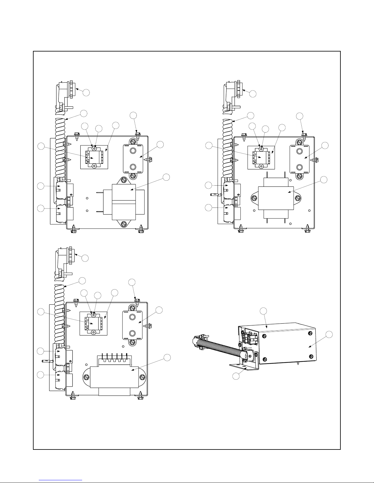
2.10 Filter Boxes
120V Assembly
(106-3981)
208-250V Assembly
(106-3988)
208-240V Assembly
(106-3989)
5
4
6
7
8
9
10
14
11
12
13
5
4
6
7
8
9
10
14
11
12
13
5
4
6
7
8
9
10
14
11
12
13
1
2
3
2-27
Page 65

ITEM PART # COMPONENT
Complete Box Assemblies
106-3981
120V (see also 806-6912)
106-3988 208-250V
106-3989 208-240V
Components
1 200-6836 Filter Box
2 200-6837 Lid
3 200-6838 Mount
4 806-7494 Plug Assembly, Non-Reversing
5 806-8021 Plug Assembly, Heater Plug
6 807-0012 Relay, 18 Amp
7 807-0141 Connector, ⅜” Right Angle
8 Transformers
807-0800 120V/24V
807-0680 208-240V/24V
807-1999 208-250V/12V & 24V
9 810-1164 Terminal Block, 1 Plc Screwless
10 812-1704 Conduit, Flex ⅜” x 13.5”
11 816-0217 Paper, Insulation
12 826-1366 Nut, 4-40 Keps Hex with External Tooth (pkg. of 25)
13 826-1359 Screw, 4-40 x ¾” Slotted Round Head (pkg. of 25)
14 809-0360 Screw, #8 x ⅜” Washer Slotted Hex Head
* 810-1421 Harness, Control Circuit
* Not illustrated.
2-28
Page 66
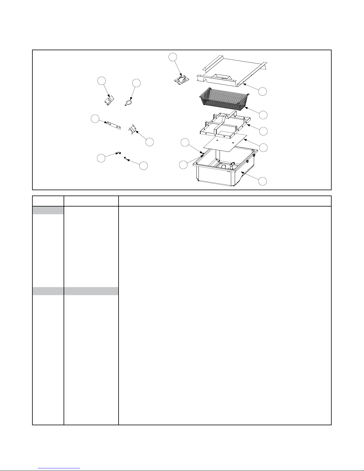
2.11 Filter Pan Assembly
7
2
6
5
1
4
3
8
9
10
11
14
12
13
ITEM PART # COMPONENT
106-3796SP
1 823-4532SP Filter Pan
2 810-2743 Crumb Tray
* 813-0568 Plug, ⅛” Socket-head Pipe
3 826-1372 Nut, Grip ¼-20 Hex (pkg. of 10)
* 816-0596 O-ring
4 810-2198 Roller, Filter Pan Rail
* 810-2012 Rail Set, Filter Pan Rail
* 826-1979 Kit, Filter Pan Roller
* 809-0191 Washer, Spring Lock, ¼”
5 200-2124 Screen, Sana Grid
6 810-2798 Ring, Hold Down
7 823-5291
8 823-5292
9 106-5141 Bracket, Shield Mounting (MJ35)
10 809-0173
11 200-9732
12 200-9715
14 826-1371 Screw, #8 x ½” Hex Head Drill Point (pkg. of 25)
13 809-0785 Screw, #14 x ¾” Slotted Head
* 824-0430 Crumb Screen
* 806-3177 Cover, Filter Cabinet
* 200-6310 Support, Rear Pan Rail
* 809-0743 Screw, 4-40 x 1 Pan Head, Stainless Steel
* 803-0170 Filter Paper, 16.5 x 25.75 (box of 100 sheets)
* 803-0002 Filter Powder (box of 80 individual packs)
* Not illustrated.
Pan Assembly, Complete (Includes 823-4532)
Other Filter Components
Lid, Filter Pan (included in kit 826-2109, 826-2110, and 826-2111)
Splash Shield (included in kit 826-2109, 826-2110, and 826-2111)
Clip, Tinnerman (included in kits 826-2109, 826-2110, and 826-2111)
Lip, Suction Fitting (included in kits 826-2109, 826-2110, and 826-2111)
Brace, Drain Spout (included in kits 826-2110 and 826-2111)
2-29
Page 67

2.12 Frypots
MJ35, Full-vat, SS
MJ45, Full-vat, CRS
MJ35, Full-vat, CRS
MJ45, Full-vat, SS
MJ45, Dual-vat, SS
4 53
21
MJ35, Full-vat, SS
(Front Flush)
7 86
MJ45, Full-vat, SS
(Front Flush)
MJ45, Dual-vat, SS
(Front Flush)
ITEM PART # COMPONENT
* Not illustrated.
Frypot Assemblies (without Insulation)
1 823-4599SP MJ 35, Full-vat, 439 Stainless Steel
2 823-3884SP MJ 45, Full-vat, 439 Stainless Steel
3 823-3871SP MJ 45, Dual-vat, 439 Stainless Steel
* 823-4492SP MJ 35, Full-vat, 439 Stainless Steel (FMP)
4 823-4754 MJ 35, Full-vat, Cold-rolled Steel
5 823-5114 MJ 45, Full-vat, Cold-rolled Steel
6 823-5644 MJ 35, Full-vat, 439 Stainless Steel (Front Flush)
7 823-5645 MJ 45, Full-vat, 439 Stainless Steel (Front Flush)
8 823-5646 MJ 45, Dual-vat, 439 Stainless Steel (Front Flush)
Frypot Assemblies (Complete)
106-4115 MJ 35, Full-vat, 439 Stainless Steel
106-2547SP MJ 45, Full-vat, 439 Stainless Steel
106-2545SP MJ 45, Dual-vat, 439 Stainless Steel
106-4116 MJ 35, Full-vat, Cold-rolled Steel
106-4838 MJ 45, Full-vat, Cold-rolled Steel
106-5867 MJ 35, Full-vat, 439 Stainless Steel (Front Flush)
106-5868 MJ 45, Full-vat, 439 Stainless Steel (Front Flush)
106-5869 MJ 45, Dual-vat, 439 Stainless Steel (Front Flush)
2-30
Page 68

2.13 Frypot Cabinetry
Frypot assemblies located in Section 2.12.
1
2
3
6
5
4
8
9
10
11
12
13
14
15
16
9
14
10
7
11
2.13.1 MJ45 Frypot Cabinetry
ITEM PART # COMPONENT
1 806-5778SP Flue Deector Box Assembly
2 810-0424
Deector, Rear Burner (integral component of Item 1)
3 806-5567SP Flue Assembly, MJ45
4 806-1095SP Front Bafe Assembly
* 106-5874 Front Bafe Assembly (Front Flush Full-vat)
* 106-5892 Front Bafe Assembly (Front Flush Dual-vat)
5 809-0409 Screw, Pilot Light Cover
6 810-0647 Holder, Pilot Light Cover Screw
7 823-5302
Cover with Sight-glass, Pilot Light (without sight-glass, 900-1090)
8 806-5566SP Rear Combustion Chamber Panel Assembly
9 900-6441 Panel, Combustion Chamber Side
10-13 816-0861
14 826-1374 Screw, #10 x ½” Washer Hex Head
Kit, Insulation (cut to t)
15 809-0173 Clip, Tinnerman
16 809-0170 Screw, #14 x ¾” Slotted Pan Head
* 210-0681 Probe Guard
* 816-0698 Insulation, Kaowool Blanket (Front Flush)
* 220-0927 Air/Heat Shield, 31”
* 220-0928 Air/Heat Shield, 15 ½”
* Not illustrated.
2-31
Page 69

2.13.2 MJ35 Frypot Cabinetry
Frypot assemblies located in Section 2.12.
All insulation is included in 826-0861 and should be cut to fit.
7
10
4
3
9
5
6
8
2
1
ITEM PART # COMPONENT
1 106-4430SP Flue Assembly, MJ35
2 900-3267 Flue Deector Box Assembly
3 806-4168SP Combustion Chamber, Front
* 106-5898 Front Bafe Assembly (Front Flush Full-vat)
4 809-0409 Screw, Pilot Light Cover
5 810-0647 Holder, Pilot Light Cover Screw
6 900-1090
7 823-0078SP Combustion Chamber, Side
* 826-0861
8 826-1374 Screw, #10 x ½” Washer Hex Head
9 809-0173 Clip, Tinnerman
10 809-0170 Screw, #14 x ¾” Slotted Pan Head
* 210-0681 Probe Guard
* 220-0927 Air/Heat Shield, 31”
* 220-0928 Air/Heat Shield, 15 ½”
* Not illustrated.
Cover, Pilot Light (with sight-glass, 823-5302)
Kit, Insulation (cut to t)
2-32
Page 70

2.14 Gas Valves and Burners
Gas Valve Conversion Kits:
Non-CE Natural to Propane: 826-1143
Non-CE Propane to Natural: 826-1144
CE Natural to Propane: 826-1200
CE Propane to Natural: 826-1201
NOTE: Red dot indicates propane/
butane pilot assembly; green dot
indicates manufactured gas; no dot
indicates natural gas.
NOTE: This style of burner heat
shield is only used with the burner
above the filter unit. All other
burners use 823-0574. See Item 6
in the parts list on the next page.
10
6
8
3
7
10
9
4
5
1
6
2
2.14.1 MJ45 Gas Valves and Burners
ITEM PART # COMPONENT
1 230-1177 Metal Deector (Target) without Stiffener, Individual
2 230-1206 Metal Deector (Target) Rear, Individual
807-1707 Ignitor, Natural
807-1708 Ignitor, Propane
3 826-1155 Ignitor Kit, Optional Piezo
4
Burner Manifold
810-2710
810-2708
810-2709
* Not illustrated.
FV (full assembly including targets, 106-3246SP)
DV, Left (full assembly including targets, 106-3245SP)
DV, Right (full assembly including targets, 106-3245SP)
MJ45 Gas Valves and Burners continued on next page
2-33
Page 71

ITEM PART # COMPONENT
5
826-1357 1.45 mm, Natural Gas (pkg. of 10)
826-1387 .86 mm, Propane/Butane Gas (pkg. of 10)
810-0407 2.15 mm, Manufactured Gas
812-1203 1.00 mm, MJ Orice
6
810-1830 Natural Gas with Thermopile (Twin Push-on Terminals)
106-1908SP Natural Gas with Thermopile (Twin Spade Terminals)
106-1909SP Pro./But. Gas with Thermopile (Twin Spade Terminals)
806-8688SP Natural Gas with Thermocouple (Co-axial Lead)
106-1911 Natural Gas, Australian (Co-axial Lead)
810-2071 Natural Gas, mV
806-8689SP Pro./But. Gas with Thermocouple (Co-axial Lead)
106-1912 Pro./But. Gas, Australian (Co-axial Lead)
810-2070 Pro./But. Gas, mV
7
823-5295
823-5296
823-0574
826-2109
826-2110
826-2111
8
810-2007 Pilot, Thermopile, Natural Gas
810-2022 Pilot, Thermopile, LP Gas
807-3485 Thermopile, Generator with Adaptor
810-1873 Thermopile 1TT (Non-CE Pilot Assemblies)
812-1284
826-1527 Kit, Thermocouple with Adapter (CE Pilot Assemblies)
810-1723 Thermocouple Adapter (CE Pilot Assemblies)
9 810-0705
812-0278
10
807-1603 mV Natural Gas
807-1604 mV Propane Gas
807-3294 24V Natural Gas (for 240V, use 807-0025)
807-3295 24V Propane Gas (for 240V, use 807-0759)
106-4214 E. I. Natural
106-4215 E. I. Propane
11
806-6710
806-6711
806-7101 mV Natural Gas
806-7102 mV Propane Gas
*
806-5895 Natural Gas, Right
806-5896 Natural Gas, Left
806-5897 Pro./But. Gas, Right
806-5894 Pro./But. Gas, Left
* 810-0691
NOTES: 1. A gas valve capacitor (P/N 806-4781) is required on gas valves used on units with thermostat controllers. 2. An
adapter kit (P/N 812-1256SP) is required to connect the high-limit thermostat to Item 11. It is included with Item 6 on Page 2-40.
Orices (for high altitude and special gasses contact Frymaster)
Pilot Assemblies, Non-CE
Pilot Assemblies, CE and Export
Burner Heat Shield Assemblies
Filter Burner Position, Left (includes bracket, 210-9729)
Filter Burner Position, Right (includes bracket, 210-9729)
Non-Filter Burner Position (includes bracket, 930-0075)
Kit, Retrot Filter Lid (includes 823-5295 and 823-5296, see Page 2-29)
Kit, Retrot Filter Lid, LH Spreader (includes 823-5295, see Page 2-29)
Kit, Retrot Filter Lid, RH Spreader (includes 823-5295, see Page 2-29)
Thermopile/Thermocouple
Thermocouple Assembly (CE, component of 826-1527)
Tube, Pilot Gas (Use with all burner assemblies except Hong Kong export units.)
Tube, Pilot Gas (Use with Hong Kong export units only.)
Gas Valves, Non-CE (see Note 1 below)
Gas Valves, CE
24V Natural Gas (see Note 2 below)
24V Propane Gas (see Note 2 below)
Mount Assembly (Ignitor, Electrode/Flame Sensor, Mount Plate)
Tube, Vent (CE, 810-1166)
2-34
Page 72

Gas Valve Conversion Kits:
(with Honeywell Pilots)
Non-CE Natural to Propane: 826-1964
Non-CE Propane to Natural: 826-1965
NOTE: Red dot indicates propane/
butane pilot assembly; green dot
indicates manufactured gas; no dot
indicates natural gas.
NOTE: This style of burner heat
shield is only used with the burner
above the filter unit. All other
burners use 823-0574. See Item 6
in the parts list on the next page.
1
10
9
6
7
4
5
6
8
3
2
2.14.2 MJ35 Gas Valves and Burners
2-35
Page 73
ITEM PART # COMPONENT
1 230-1178 Deector (Target) without Stiffener, Individual
2 230-1180 Deector (Target) Rear, Individual
807-1707 Ignitor, Natural
807-1708 Ignitor, Propane
3 826-1155 Ignitor Kit, Optional Piezo
4 810-1862
5
826-1353 1.7 mm, Natural Gas (pkg. of 10)
826-1354 1.05 mm, Propane/Butane Gas (pkg. of 10)
810-0407 2.15 mm, Manufactured Gas
812-1203 1.00 mm, MJ Orice
6
810-1830 Natural Gas with Thermopile (Twin Push-on Terminals)
106-1908SP Natural Gas with Thermopile (Twin Spade Terminals)
106-1909SP Pro./But. Gas with Thermopile (Twin Spade Terminals)
806-8688SP Natural Gas with Thermocouple (Co-axial Lead)
106-1911 Natural Gas, Australian (Co-axial Lead)
806-8689SP Pro./But. Gas with Thermocouple (Co-axial Lead)
106-1912 Pro./But. Gas, Australian (Co-axial Lead)
7 823-5295
823-5296
823-0574
826-2109
826-2110
826-2111
8
810-2007 Pilot, Thermopile, Natural Gas
810-2022 Pilot, Thermopile, LP Gas
807-3485 Thermopile, Generator with Adaptor
810-1873 Thermopile 1TT (Non-CE Pilot Assemblies)
9 810-0705
812-0278
10
807-1603 mV Natural Gas
807-1604 mV Propane Gas
807-3294 24V Natural Gas (for 240V, use 807-0025)
807-3295 24V Propane Gas (for 240V, use 807-0759)
810-0786 E. I. Natural
810-0787 E. I. Propane
* 810-0691 Tube, Vent
NOTE: A gas valve capacitor (P/N 806-4781) is required on gas valves used on units with thermostat controllers.
FV, Burner Manifold (full assembly including targets, 106-4205SP)
Orices (for high altitude and special gasses contact Frymaster)
Pilot Assemblies, Non-CE
Pilot Assemblies, CE and Export
Burner Heat Shield Assemblies
Filter Burner Position, Left (includes bracket, 210-9729)
Filter Burner Position, Right (includes bracket, 210-9729)
Non-lter Burner Position (includes bracket, 930-0075)
Kit, Retrot Filter Lid (includes 823-5295 and 823-5296, see Page 2-29)
Kit, Retrot Filter Lid, LH Spreader (includes 823-5295, see Page 2-29)
Kit, Retrot Filter Lid, RH Spreader (includes 823-5295, see Page 2-29)
Thermopile/Thermocouple
Tube, Pilot Gas (Use with all burner assemblies except Hong Kong export units.)
Tube, Pilot Gas (Use with Hong Kong export units only.)
Gas Valves, Non-CE (see note below)
2-36
Page 74

2.15 Oil Return Components
Filter Suction Manifold
Filter Return Manifold
10
6
7
8
9
11
12
13
5
9
10
12
13
4
115V Pump/Motor Assembly shown.
18
12
2
20
3
27
29
13
Dual-Vat
(106-4003)
Oil Return Handle
Full-Vat Assembly
(106-4002)
1
28
27
26
25
22
24
21
23
24
30
15
14
16
18
9
19
17
2-37
Page 75

ITEM PART # COMPONENT
1
106-4002SP FV Oil Return Assembly
106-4003SP DV Oil Return Assembly
2
826-1712
826-1756
826-1270
826-1755
3 826-1264 Pump, Viking 4 GPM 2-piece
106-3987
4 813-0251 Nipple, ½” x 3.5 BM
5 823-4739 Bracket, Suction Nipple
106-3986
6 813-0247 Nipple, ½” x 3.5 BM
7 823-4737 Bracket, Suction Nipple
8 810-1668 Adapter, Male
* 810-1339 Flexline, 4.5”
9 810-1669 Adapter, Female
10 810-1680 Flexline, 6.5”
11 810-1160 Flexline, ⅝” x 3”
12 813-0062 Elbow, ½” 90° BM
13 813-0165 Elbow, Street ½” NPT BM
14 807-2104
15 200-9065
16 816-0644
* 811-0746
* 811-0861
* 807-1472
* 807-1473
* 806-8065 100V, 25W, 18”
* 806-5933 120V, 25W, 18”
* 806-5934 208/240V, 25W, 18”
* 806-6733 250V, 70W, 56”
* 106-5011 Extension Harness
* 826-2100 Kit, Retrot 120V Heater
17 823-4743 Connector, Female Suction
* 813-0156 Pipe Plug, ½”
* 810-1003 Valve, 180° 3-way Ball
* 807-2484 Valve, Solenoid Vent
18 813-0275 Nipple, ½” x 9 NPT BM Pipe
19 813-0087 Nipple, ½” x 1.5 NPT BM
20 816-0093 Gasket, Pump and Motor
21 816-0220
22 900-2110
23 806-8342
24 806-9385
* Not illustrated.
Handle Assemblies, Oil Return Valve
Pump and Motor
100-120V, 60 Hz (motor and gasket)
208V, 50/60 Hz (motor and gasket)
230V, 50/60 Hz (motor and gasket)
250V, 50/60 Hz (motor and gasket)
Filter Return Manifold (see additional components below)
Filter Suction Manifold (see additional components below)
Included with Filter Return/Suction Manifolds
Oil Return Handle
Microswitch (included with Item 1)
Handle (included with Item 1)
Grip (included with Item 1)
Miscellaneous
Aluminum Tape (150’ roll)
Foam Tape (sold by the foot)
Heater Strip 120V-40W 56” (for 120V fryers)
Heater Strip 240V-70W 56” (for 208-240V fryers)
Heater Tape
Insulation, Drain Safety Box (included with Item 1)
Cover, Oil Return Microswitch (included with Item 1)
Support, Oil Return Valve (included with Item 1)
Support, Microswitch Mount, FV (included with Item 1)
Oil Return Components continued on next page . . .
2-38
Page 76

2
3
6
5
4
1
ITEM PART # COMPONENT
24 900-2112
25 826-1376 Nut, 10-32 Keps Hex (pkg. of 10)
26 826-1366 Nut, 4-40 Keps Hex with External Tooth (pkg. of 25)
27 809-0194 Washer, Flat 5/16” SAE
28 809-0056 Nut, 5/16”-18 Hex
29 809-0514 Capscrew, 5/16”-18NC Hex SAE
* WIR0220 Pump Wiring Assembly
30 826-1359 Screw, 4-40 x ¾” Keps Hex (pkg. of 25)
* 826-2118 Kit, 100 VAC, Rear Disposal
* 826-2119 Kit, 120 VAC, Rear Disposal
* 826-2120 Kit, 220/240 VAC, Rear Disposal
* 826-2121 Kit, 250 VAC, Rear Disposal
* Not illustrated.
Support, Microswitch Mount, DV (included with Item 1)
2.16 Power Shower
ITEM PART # COMPONENT
Power Shower Assembly
806-4542SP MJ35
806-4503SP MJ45
Components
1 823-1522 Power Shower Body, MJ35
2 823-1485 Power Shower Body, MJ45
3 809-0415 Screw, Clean-out
4 826-1344 O-ring
5 826-1390 Seal
6 814-0001 Grip
2-39
Page 77

2.17 Thermostats and Timers
5
8
6
7
NOTE: Leads on Items 1, 2, 3, 5, and 6
are depicted shorter than they actually are.
15
12
11
1111111111111111
1
1111111111111111
2
1111111111111111
3
16
17
19
4
18
9
10
20
14
13
ITEM PART # COMPONENT
Operating Thermostat Assembly, Fenwall 4”
1 806-0183 With Two Blue Insulated Push-on Terminals, 24V (MJ35 & 45, Non-CE)
2 806-7972 With One Wire Push-on, One Fork Spade Terminal, Millivolt (MJ35, CE)
* 106-7036 With One Wire Push-on, One Fork Spade Terminal, Millivolt (MJ45, CE)
3 806-9617 With One Blue Insulated Push-on, One Fork Spade Terminal (Millivolt, CE)
4 806-0087SP Thermostat Dial Plate Assembly
High-Limit Thermostat
5 806-7908 425°F High-limit (Non-CE)
6 806-7550 218°C High-limit (CE; includes adapter for gas valve hookup. See note on
Flex Shaft
* 810-0999
7 810-0345 Shaft, 7.25” Thermostat Flexible Extension
8 810-1651 Shaft, 5.50” Thermostat Flexible Extension
* 810-0276 Shaft, 2.25” Thermostat Flexible Extension
9 823-1330 Mounting Bracket
Timers, Basket Lift
10 826-1552 15-minute Electronic Timer, 120V-60Hz (Push-button)
* 826-1667 15-minute Electronic Timer, 240V
11 810-0585 15-minute Mechanical Timer
12 910-1551 15-minute Mechanical Timer Bezel
Knobs
13 810-1823 Push-Button, 15-minute Electronic Timer
14 810-1822 Knob, 15-minute Electronic Timer
15 810-1287 Knob, 15-minute Mechanical Timer
16 810-0110 Knob, Fenwal Thermostat with Two Allenhead Screws
17 810-0334 Knob, with Skirt
18 810-0387 Knob, Control
19 826-1395 Plug Button (pkg. of 10)
* 810-0388 Knob, 1” Black
* 826-1575 Kit, Retrot 5-minute Timer
20 807-4134 Buttery/Envelope Adapter (CE)
* 106-4386SP Toggle Switch, Optional
* 806-4206 Temperature Probe
* 210-0681 Probe Guard
* Not illustrated.
Page 2-34.)
Flex Shaft, Control Panel Mount Assembly, 9 ¼” overall (8”, 810-2863)
2-40
Page 78
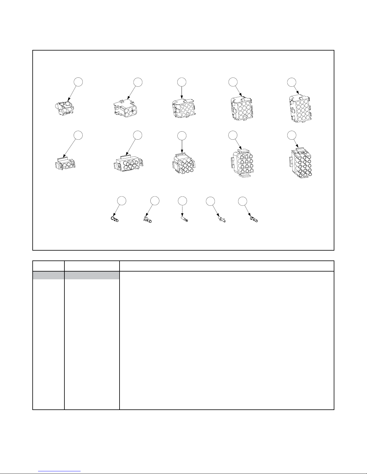
2.18 Wiring Harnesses, Pin Terminals, and Power Cords
14 15
13
11
12
9 10
8
6
7
4
5
3
1
2
ITEM PART # COMPONENT
1 807-1068 2-pin Female
2 807-0158 6-pin Female
3 807-0156 9-pin Female
4 807-0159 12-pin Female
5 807-0875 15-pin Female
6 807-1067 2-pin Male
7 807-0157 6-pin Male
8 807-0155 9-pin Male
9 807-0160 12-pin Male
10 807-0804 15-pin Male
11 826-1332 Terminal, Female Split Pin (pkg. of 25)
12 826-1333 Terminal, Male Split Pin (pkg. of 25)
13 807-2518 Plug, Mate-N-Lock (Dummy Pin)
14 826-1331 Terminal, M&L Female Split Pin (pkg. of 25)
15 826-1336 Terminal, M&L Male Split Pin (pkg. of 25)
* 807-0154 Cord Set
* Not illustrated.
Connectors
2-41
Page 79

2.19 Garland Range (S35) Parts
ITEM PART # COMPONENT
Cabinetry
* 806-6741 Cabinet Assembly, H35
* 900-2266 Cabinet, Back/Upper
* 823-2282 Fluecap
* 824-0517 Topcap
* 806-6765 Door Assembly
* 806-3943SP Frypot Assembly
* 106-4430 Flue Assembly
* 810-1195 Top Back Guard
* 806-6985 Wiring Harness
* 810-1306 1/2” Brass Manual Gas Valve
* KIT1653 Garland Piezo Ignitor Kit
* Not illustrated.
2-42
Page 80

Frymaster, L.L.C., 8700 Line Avenue, PO Box 51000, Shreveport, Louisiana 71135-1000
Shipping Address: 8700 Line Avenue, Shreveport, Louisiana 71106
TEL 1-318-865-1711 FAX (Parts) 1-318-219-7140 FAX (Tech Support) 1-318-219-7135
PRINTED IN THE UNITED STATES
SERVICE HOTLINE
1-800-551-8633
819-6092
APRIL 2006
 Loading...