


FREIGHTLINER FLD 120
CPL SYSTEMS // GROENEVELD
AUTOMATICIC GREASINGI SYSTEM
INSTALLATIONI I MANUAL FOR
CUSTOMER SERVICEI TECHNICIANSI I
May 6, 1999 |
1 |
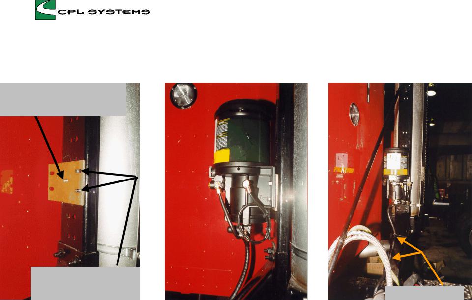
PUMP MOUNTING - FLD 120
Mount bracket with 5/16” - 18 x 1” bolt, 5/16” flat washer and lockwasher through existing hole
Use drill template DT003 to |
|
drill two 11/32” holes in stack |
|
support to mount pump |
large tyraps two spots |
Pump mounted on the exhaust stack support using ‘FREIGHT’ bracket, 5/16” - 18 x 1 1/2” bolts, nuts & washers
May 6, 1999 2
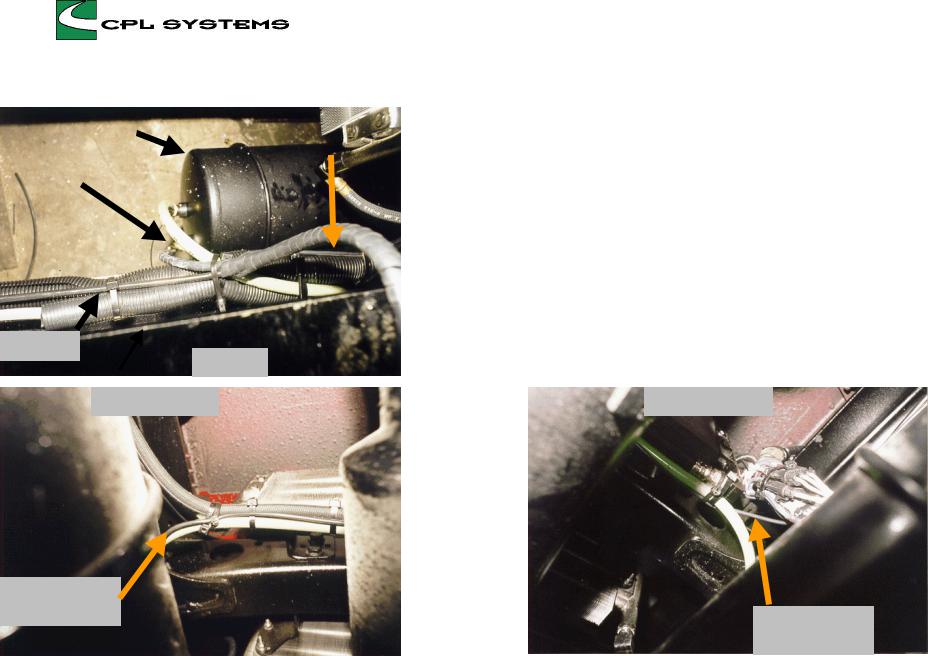
AIR & ELECTRICAL - FLD 120
secondary air tank |
|
electrical, timer |
|
|
|
|
to solenoid |
|
|
||
|
|
|
|
|
|
|
|
air supply |
|
|
|
|
|
|
|
main line
top view
bottom view L/S
Air Supply: take it from the highest outlet available in a ‘secondary’ air tank (i.e.. Top, end or side). Never connect to the bottom, never connect to a ‘wet’ tank, never connect to a ‘primary’ tank
Electrical - Timer to Solenoid: route with existing hoses etc. where possible - do not crush any air lines or wiring with tyraps
General: avoid sharp bends and corners, protect with spirap where necessary
bottom view R/S
electrical, timer
to solenoid
electrical, timer to solenoid
May 6, 1999 |
3 |
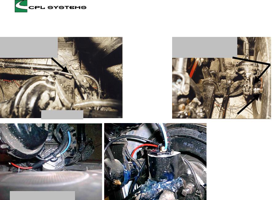
LEFT FRONT WHEEL - FLD 120
Most Freightliners have shocks - this routing will help avoid an interference
draglink, top view
kingpin & cam tube, top view
See note on right front wheel page about the direction of the slack fitting
|
cam tube, front |
|
|
|
|
|
|
|
Important: fill cam tube with |
||
|
grease before removing the zerk |
||
|
fitting. Fill until grease can be seen |
||
|
squeezing out between the cam |
||
|
tube bushing and the slack |
||
|
adjuster. Do Not assume it has been |
||
|
done already even if someone says |
||
|
it has. Make sure! Always cycle the |
||
|
steering from ‘lock to lock’ to make |
||
|
sure sufficient clearance is |
||
|
available between fittings and lines |
||
left knuckle |
|||
to all components |
|||
|
|||
May 6, 1999 |
4 |
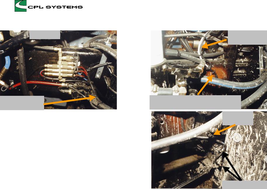
LEFT FRONT FRAME RAIL - FLD120
12 port block
follow brake hose to brake chamber
Electrical - timer to pressure switch: coil some extra wire at the manifold so the pressure switch and waterproof connector can be serviced easily.
General: grease lines are to be routed along the brake hose from end to end. Install a large tyrap on the brake hose fitting at the frame end, small tyraps every 3 or 4” along the brake hose and a large tyrap, double wrapped, on the brake hose fitting at the brake chamber end. Tyrap to the brake hose only,do not include any ABS wiring in CPL tyraps.
electrical, timer to pressure switch
triple grease line, blue and black to the spring shackle, red to the transmission cross shaft
large tyrap to huck bolt
spring shackle points
May 6, 1999 |
5 |

FIFTH WHEEL
(3500 series on a Freightliner FLD 120, manifold mounted at the front of the slide plate)
secondary lining |
|
These studs need to be ground off flush with the nuts |
|
|
|
large tyraps on main line
This mainline to manifolds on fifth wheel deck could be routed a little different to improve the installation
Lines to be spiraped back to where movement begins, tyrap there too
This blue line represents ideal routing to minimize movement and vibration
keep manifold mounted close to the frame rail, out of harm’s way. Never drill holes in the frame rail flange.
large tyraps
do not put anything between the torque rod / bracket and the fifth wheel deck - it may get crushed !
May 6, 1999 |
6 |
 Loading...