


ARGOSY®
Driver’s Manual
STI-385-2
A24-00879-000

Foreword
Introduction
This manual provides information needed to operate and understand the vehicle and its components. More detailed information is contained in the Owner’s Warranty Information for North America booklet, and in the vehicle’s workshop and maintenance manuals.
Custom-built Freightliner vehicles are equipped with various chassis and cab components. Not all of the information contained in this manual applies to every vehicle. For details about components in your vehicle, refer to the chassis specification pages included in all new vehicles and to the component information label, located inside the vehicle.
For your reference, keep this manual in the vehicle at all times.
IMPORTANT: Descriptions and specifications in this manual were in effect at the time of printing. Freightliner Trucks reserves the right to discontinue models and to change specifications or design at any time without notice and without incurring obligation. Descriptions and specifications contained in this publication provide no warranty, expressed or implied, and are subject to revisions and editions without notice.
Environmental Concerns and
Recommendations
Whenever you see instructions in this manual to discard materials, you should first attempt to reclaim and recycle them. To preserve our environment, follow appropriate environmental rules and regulations when disposing of materials.
Event Data Recorder
This vehicle is equipped with one or more devices that record specific vehicle data. The type and amount of data recorded varies depending on how the vehicle is equipped (such as the brand of engine,
if an air bag is installed, or if the vehicle features a collision avoidance system, etc.).
Customer Assistance Center
Having trouble finding service? Call the Customer Assistance Center at 1-800-385-4357 or 1-800-FTL- HELP. Call night or day, weekdays or weekends, for dealer referral, vehicle information, breakdown coordination, or Fleetpack assistance. Our people are knowledgeable, professional, and committed to following through to help you keep your truck moving.
© 2007–2015 Daimler Trucks North America LLC. All rights reserved. Daimler Trucks North America LLC is a Daimler
company.
No part of this publication, in whole or part, may be translated, reproduced, stored in a retrieval system, or transmitted in any form by any means, electronic, mechanical, photocopying, recording, or otherwise, without the prior written permission of Daimler Trucks North America LLC. For additional information, please contact Daimler Trucks North America LLC, Service Systems and Documentation, P.O. Box 3849, Portland OR 97208–3849 U.S.A. or refer to www.Daimler-TrucksNorthAmerica.comand www.FreightlinerTrucks.com.
STI-385-2 (11/14)
Part Number A24-00879-000
Printed in U.S.A.

Contents
Chapter |
|
Page |
|
Introduction, Environmental Concerns and Recommendations, |
Foreword |
|
Event Data Recorder, Customer Assistance Center . . . . . . . . . . . . . . . . . . . . . . . |
|
1 |
Vehicle Identification . . . . . . . . . . . . . . . . . . . . . . . . . . . . . . . . . . . . . . . . . . . . . . . . . |
. . . . . 1.1 |
2 |
Vehicle Access . . . . . . . . . . . . . . . . . . . . . . . . . . . . . . . . . . . . . . . . . . . . . . . . . . . . . |
. . . . . 2.1 |
3 |
Electrical System . . . . . . . . . . . . . . . . . . . . . . . . . . . . . . . . . . . . . . . . . . . . . . . . . . . . |
. . . . 3.1 |
4 |
Instruments . . . . . . . . . . . . . . . . . . . . . . . . . . . . . . . . . . . . . . . . . . . . . . . . . . . . . . . . . |
. . . . 4.1 |
5 |
Driver Controls . . . . . . . . . . . . . . . . . . . . . . . . . . . . . . . . . . . . . . . . . . . . . . . . . . . . . . |
. . . . 5.1 |
6 |
Climate Control . . . . . . . . . . . . . . . . . . . . . . . . . . . . . . . . . . . . . . . . . . . . . . . . . . . . . . |
. . . . 6.1 |
7 |
Seats and Restraints . . . . . . . . . . . . . . . . . . . . . . . . . . . . . . . . . . . . . . . . . . . . . . . . . |
. . . . 7.1 |
8 |
Cab and Sleeper Features . . . . . . . . . . . . . . . . . . . . . . . . . . . . . . . . . . . . . . . . . . . . . |
. . . . 8.1 |
9 |
Engine Starting, Operation, and Shutdown . . . . . . . . . . . . . . . . . . . . . . . . . . . . . . . . |
. . . . 9.1 |
10 |
Optional Engine Systems . . . . . . . . . . . . . . . . . . . . . . . . . . . . . . . . . . . . . . . . . . . . . . |
. . . 10.1 |
11 |
Emissions Reduction Components . . . . . . . . . . . . . . . . . . . . . . . . . . . . . . . . . . . . . . |
. . . 11.1 |
12 |
Brake System . . . . . . . . . . . . . . . . . . . . . . . . . . . . . . . . . . . . . . . . . . . . . . . . . . . . . . . |
. . . 12.1 |
13 |
Steering System . . . . . . . . . . . . . . . . . . . . . . . . . . . . . . . . . . . . . . . . . . . . . . . . . . . . . |
. . . 13.1 |
14 |
Manual Transmissions and Clutch . . . . . . . . . . . . . . . . . . . . . . . . . . . . . . . . . . . . . . . |
. . . 14.1 |
15 |
Automated Transmissions . . . . . . . . . . . . . . . . . . . . . . . . . . . . . . . . . . . . . . . . . . . . . |
. . . 15.1 |
16 |
Drive Axle Feature Operation . . . . . . . . . . . . . . . . . . . . . . . . . . . . . . . . . . . . . . . . . . |
. . . 16.1 |
17 |
Fifth Wheels . . . . . . . . . . . . . . . . . . . . . . . . . . . . . . . . . . . . . . . . . . . . . . . . . . . . . . . . |
. . . 17.1 |
18 |
Trailer Couplings . . . . . . . . . . . . . . . . . . . . . . . . . . . . . . . . . . . . . . . . . . . . . . . . . . . . . |
. . . 18.1 |
19 |
Headlight Aiming . . . . . . . . . . . . . . . . . . . . . . . . . . . . . . . . . . . . . . . . . . . . . . . . . . . . . |
. . . 19.1 |
20 |
Cab Appearance . . . . . . . . . . . . . . . . . . . . . . . . . . . . . . . . . . . . . . . . . . . . . . . . . . . . . |
. . . 20.1 |
21 |
In an Emergency . . . . . . . . . . . . . . . . . . . . . . . . . . . . . . . . . . . . . . . . . . . . . . . . . . . . |
. . . 21.1 |
22 |
Preand Post-Trip Checklists . . . . . . . . . . . . . . . . . . . . . . . . . . . . . . . . . . . . . . . . . . |
. . . 22.1 |
23 |
Preand Post-Trip Inspections and Maintenance . . . . . . . . . . . . . . . . . . . . . . . . . . . |
. . . 23.1 |
|
Index . . . . . . . . . . . . . . . . . . . . . . . . . . . . . . . . . . . . . . . . . . . . . . . . . . . . . . . . . . . . . . |
. . . . I.1 |

1
Vehicle IdentiÞcation
Component Information Label . . . . . . . . . . . . . . . . . . . . . . . . . . . . . . . . . . . . . . . . . . . . . . . . . . . . . . . |
1.1 |
Vehicle IdentiÞcation
Component Information Label
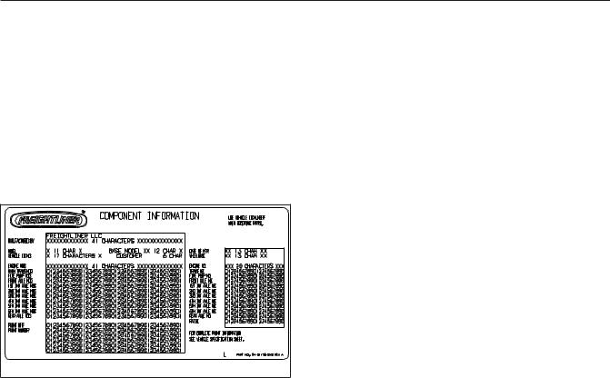
The component information label lists the vehicle model, identification number, and major component models. It also lists the major assemblies and installations shown on the chassis specification sheet. The component information label is typically attached to the passenger-side dash. An illustration of the label is shown in Fig. 1.1.
02/20/2012 |
f080176 |
Fig. 1.1, Component Information Label
1.1

2
Vehicle Access
Door Locks and Handles . . . . . . . . . . . . . . . . . . . . . . . . . . . . . . . . . . . . . . . . . . . . . . . . . . . . . . . . . . . 2.1 Cab Access, Fixed Steps . . . . . . . . . . . . . . . . . . . . . . . . . . . . . . . . . . . . . . . . . . . . . . . . . . . . . . . . . . . 2.1 Cab Access, Mobile Stairs . . . . . . . . . . . . . . . . . . . . . . . . . . . . . . . . . . . . . . . . . . . . . . . . . . . . . . . . . . 2.4 Back-of-Cab Access . . . . . . . . . . . . . . . . . . . . . . . . . . . . . . . . . . . . . . . . . . . . . . . . . . . . . . . . . . . . . . . 2.7 Opening the Grille . . . . . . . . . . . . . . . . . . . . . . . . . . . . . . . . . . . . . . . . . . . . . . . . . . . . . . . . . . . . . . . . 2.8 Cab Tilt System . . . . . . . . . . . . . . . . . . . . . . . . . . . . . . . . . . . . . . . . . . . . . . . . . . . . . . . . . . . . . . . . . . 2.9
Vehicle Access
Door Locks and Handles
One common key operates the ignition switch and all of the door locks.
IMPORTANT: Each key is numbered. Record the number so a duplicate key can be made, if needed.
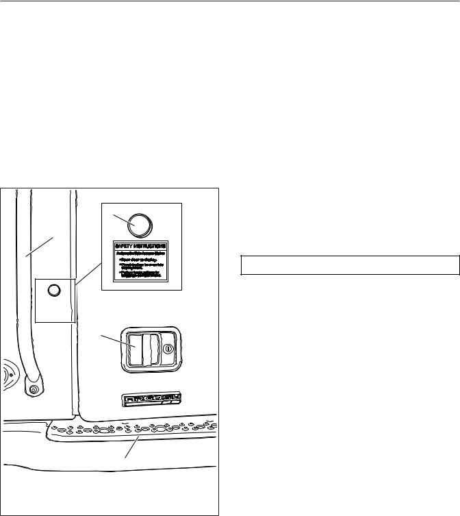
To unlock the right-hand door from outside the cab, insert the key in the lock and turn it one-quarter turn counterclockwise. Turn the key to the original position to remove it. See Fig. 2.1.
|
|
4 |
|
|
3 |
|
|
|
2 |
|
|
|
|
1 |
|
05/03/2012 |
|
f720751 |
|
1. |
Exterior Deck |
4. |
Mobile Stairs Override |
2. |
Door Handle |
|
Button |
3. |
Forward Grab Handle |
|
|
Fig. 2.1, Door Exterior (right side shown)
To unlock the left-hand door from outside the cab, insert the key in the lock and turn it one-quarter turn clockwise. Turn the key counterclockwise to the origi-
nal position to remove it. Pull out on the paddle handle to open the door.
NOTE: The cab door locks can be operated when the doors are open.
To lock a door from outside the cab, insert the key in the lock and turn it opposite the unlocking direction (counterclockwise for the left-hand door, clockwise for the right-hand door). See Fig. 2.2.
To lock a door from inside the cab, push the lock knob down or press the automatic lock button on the door armrest, depending on what the vehicle is equipped with. See Fig. 2.2. To unlock the door from inside, pull the lock knob up or press the unlock button on the door armrest, depending on what the vehicle is equipped with.
Cab Access, Fixed Steps
 WARNING
Wet or dirty shoes greatly increase the chance of slipping or falling. If your shoes are wet or dirty, be especially careful when entering or exiting the vehicle.
Always maintain three-point contact with the vehicle when entering or exiting the cab. Threepoint contact means both feet and one hand, or both hands and one foot.
Do not jump from the vehicle.
The grab handles, access steps, and steering wheel are all part of the cab access system. Use these "helping hands" when getting into or out of the cab to increase your security and comfort.
Left Side Entry
1.Open the left-hand door and place anything that you are carrying in the cab.
2.Grasp the aft grab handle with your right hand and the forward grab handle with your left hand. See Fig. 2.3.
3.Place your right foot on the bottom step and pull yourself up.
4.Place your left foot on the middle step, reaching higher on both grab handles.
2.1

Vehicle Access
|
2 |
3 |
4 |
|
|
|
1 |
04/16/2012 |
|
f720747 |
|
1. |
Door Pocket |
4. |
Upper Door Grab |
2. |
Lock Knob |
|
Handle |
3. |
Door Handle |
|
|
Fig. 2.2, Door Interior
5.Place your right foot on the top step and pull yourself up.
NOTE: The left side of the cab is equipped with an A-pillar grab handle or the steering wheel, depending on whether the vehicle is left-hand drive (LHD) or right-hand drive (RHD).
6.Move your right hand to the forward grab handle and your left hand to the steering wheel or A-pillar grab handle, then place your left foot on the deck.
|
|
|
4 |
5 |
6 |
1 |
2 |
3 |
|
|
|
|
|
7 |
|
|
|
|
|
8 |
|
|
|
|
|
9 |
|
|
|
04/27/2012 |
|
|
|
f720748 |
|
1. |
Upper Door Grab |
5. |
Forward Grab Handle |
||
|
Handle |
6 |
Aft Grab Handle |
|
|
2. |
Door Pocket |
7. |
Top Step |
|
|
3. |
Exterior Deck |
8. |
Middle Step |
|
|
4. |
A-Pillar Grab Handle |
9. |
Bottom Step |
|
|
Fig. 2.3, Fixed Steps and Grab Handles, Left Side (RHD
shown)
7.Step into the cab with your right foot first.
Left Side Exit
IMPORTANT: Do not attempt to exit the cab while carrying any items in your hands.
1.If you take items with you, place them in an accessible location on the seat or cab floor. Make sure they will not get in your way as you exit.
 WARNING
Always face in when exiting the cab. Do not attempt to exit with your back to the cab, as you
2.2
Vehicle Access
would going down a ßight of stairs. It is easier to slip or lose your balance. If you slip when exiting in this way, there is a greater likelihood of personal injury.
NOTE: The left side of the cab is equipped with an A-pillar grab handle or the steering wheel, depending on whether the vehicle is LHD or RHD.
2.Grasp the steering wheel or A-pillar grab handle with your left hand, place your right hand on the forward sidewall grab handle, and place both feet on the deck, facing into the cab.
3.Grasp the forward grab handle with your left hand and move your right hand to the aft grab handle.
4.Move your right foot to the top step.
5.Move your left foot to the middle step and lower your hands on both grab handles.
6.Move your right foot to the bottom step.
7.Step to the ground with your left foot first.
Right Side Entry
1.Open the right-hand door and place anything that you are carrying in the cab.
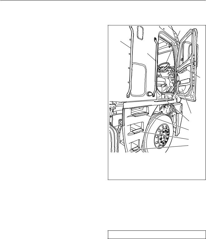
2.Grasp the aft sidewall grab handle with your left hand and the forward grab handle with your right hand. See Fig. 2.4.
3.Place your left foot on the bottom step and pull yourself up.
4.Place your right foot on the middle step, reaching higher on both grab handles.
5.Place your left foot on the top step and pull yourself up.
NOTE: The right side of the cab is equipped with an A-pillar grab handle or the steering wheel, depending on whether the vehicle is LHD or RHD.
6.Move your left hand to the forward grab handle and your right hand to the steering wheel or A-pillar grab handle, then place your right foot on the deck.
7.Step into the cab with your left foot first.
|
|
|
7 |
|
9 |
|
|
|
|
8 |
|
|
|
|
6 |
|
|
|
5 |
|
|
|
4 |
|
|
|
3 |
|
|
|
2 |
|
|
|
1 |
05/04/2012 |
|
f720749 |
|
1. |
Bottom Step |
6 |
Upper Door Grab |
2. |
Middle Step |
|
Handle |
3. |
Top Step |
7. |
Steering Wheel |
4. |
Exterior Deck |
8. |
Forward Grab Handle |
5. |
Door Pocket |
9. |
Aft Grab Handle |
Fig. 2.4, Fixed Steps and Grab Handles, Right Side (RHD shown)
Right Side Exit
IMPORTANT: Do not attempt to exit the cab while carrying any items in your hands.
1.If you take items with you, place them in an accessible location on the seat or cab floor. Make sure they will not get in your way as you exit.
 WARNING
Always face in when exiting the cab. Do not attempt to exit with your back to the cab, as you would going down a ßight of stairs. It is easier to slip or lose your balance. If you slip when exiting
2.3
Vehicle Access
in this way, there is a greater likelihood of personal injury.
NOTE: The right side of the cab is equipped with an A-pillar grab handle or the steering wheel, depending on whether the vehicle is LHD or RHD.
2.Grasp the steering wheel or A-pillar grab handle with your right hand, place your left hand on the forward sidewall grab handle, and place both feet on the deck, facing into the cab.
3.Grasp the forward grab handle with your right hand and move your left hand to the aft grab handle.
4.Move your left foot to the top step.
5.Move your right foot to the middle step and lower your hands on both grab handles.
6.Move your left foot to the bottom step.
7.Step to the ground with your right foot first.
Cab Access, Mobile Stairs
 WARNING
Wet or dirty shoes greatly increase the chance of slipping or falling. If your shoes are wet or dirty, be especially careful when entering or exiting the vehicle.
Always maintain three-point contact with the vehicle when entering or exiting the cab. Threepoint contact means both feet and one hand, or both hands and one foot.
Do not jump from the vehicle.
The grab handles, access steps, and steering wheel are all part of the cab access system. Use these "helping hands" when getting into or out of the cab. They will increase your security and comfort.
The mobile stairs will deploy when the cab door is opened. As the stairs deploy, an audible alert sounds outside the vehicle. If anything prevents deployment of the stairs, a buzzer will sound and an indicator will illuminate on the dash.
The cab stairs will not operate under the following conditions:
• parking brake is not set
•vehicle is in motion (stairs automatically stow if the vehicle begins to move)
•sensors detect weight on the stairs
•cab is tilted
•an obstacle is encountered in the stair travel path
•the disable button is pressed
To prevent deployment of the stairs from outside the vehicle, press the button on the side of the cab, directly above the stairs, before opening the door. See
Fig. 2.1.
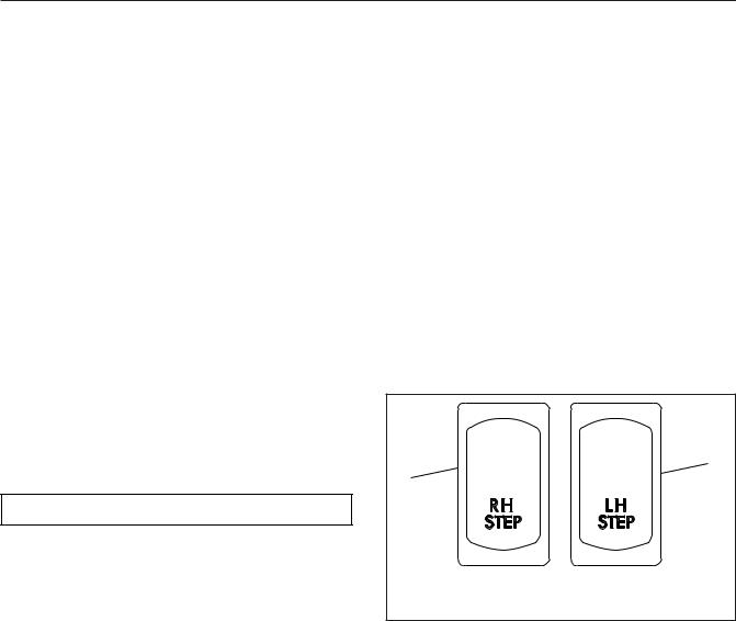
To prevent deployment of the stairs from inside the cab, press the dash rocker switch labeled RH STEP or LH STEP while opening the cab door. See
Fig. 2.5.
|
|
|
2 |
1 |
|
|
|
04/24/2012 |
|
f611182 |
|
1. |
Right-Hand Stairs |
2. |
Left-Hand Stairs |
|
Switch |
|
Switch |
Fig. 2.5, Mobile Stairs Deployment Switches
NOTE: Pressing the disable button or switch will disable the stairs for one cycle of opening and closing the door. You must press the disable button each time you want to prevent deployment of the stairs.
Left Side Entry
1.Open the left-hand door and place anything that you are carrying in the cab.
2.Grasp the aft grab handle (Fig. 2.6) with your right hand and grab the forward grab handle with your left hand, reaching up as far as is comfortable.
3.Place your right foot on the bottom step and pull yourself up.
2.4
Vehicle Access
7
6
5
4
3
2
1
08/10/98 |
|
f720309 |
|
1. |
Bottom Step |
5. |
Aft Grab Handle |
2. |
Middle Step |
6. |
Forward Grab Handle |
3. |
Top Step |
7. |
Steering Wheel |
4. |
Top Deck |
|
|
Fig. 2.6, Mobile Stairs, Left-Hand Side
4.Place your left foot on the middle step and pull yourself up.
5.Move your left hand to the forward grab handle, then place your left foot on the top step.
NOTE: The left side of the cab is equipped with an A-pillar grab handle or the steering wheel, depending on whether the vehicle is LHD or RHD.
6.Pull yourself up and place your right foot on the top deck and move your left hand to the A-pillar grab handle or steering wheel.
7.Move your right hand to the steering wheel or A-pillar grab handle.
8.With both hands gripping the steering wheel or A-pillar grab handle, move your right foot into the cab.
Left Side Exit
IMPORTANT: Do not attempt to exit the cab while carrying any items in your hands.
NOTE: The left side of the cab is equipped with an A-pillar grab handle or the steering wheel, depending on whether the vehicle is LHD or RHD.
1.Grasp the steering wheel or A-pillar grab handle with both hands, and stand on the deck at the top of the stairs facing into the cab.
2.With your right hand, grasp the forward grab handle.
3.Move your right foot to the top step.
4.Move your left hand to the forward grab handle and move your left foot to the middle step.
5.Move your right hand to the aft grab handle and move your right foot to the bottom step.
6.Step to the ground with your left foot.
Right Side Entry
1.Open the right-hand door and place anything that you are carrying in the cab.
2.Grasp the aft grab handle with your left hand and grab the forward grab handle with your right hand, reaching up as far as you’re comfortable. See Fig. 2.7.
3.Place your left foot on the bottom step and pull yourself up.
4.Place your right foot on the middle step and pull yourself up.
5.Move your right hand to the forward grab handle, then place your right foot on the top step.
NOTE: The right side of the cab is equipped with an A-pillar grab handle or the steering wheel, depending on whether the vehicle is LHD or RHD.
6.Pull yourself up and place your left foot on the top deck and move your right hand to the A-pillar grab handle or steering wheel.
7.Move your left hand to the steering wheel or A-pillar grab handle.
2.5
Vehicle Access
|
|
|
7 |
|
9 |
|
|
|
|
8 |
|
|
|
|
6 |
|
|
|
5 |
|
|
|
4 |
|
|
|
3 |
|
|
|
2 |
|
|
|
1 |
05/16/2012 |
|
f720750 |
|
1. |
Bottom Step |
6 |
Upper Door Grab |
2. |
Middle Step |
|
Handle |
3. |
Top Step |
7. |
Steering Wheel |
4. |
Exterior Deck |
8. |
Forward Grab Handle |
5. |
Door Pocket |
9. |
Aft Grab Handle |
Fig. 2.7, Mobile Stairs and Grab Handles, Right-Hand Side (RHD shown)
8.With both hands gripping the steering wheel or A-pillar grab handle, move your left foot into the cab.
Right Side Exit
IMPORTANT: Do not attempt to exit the cab while carrying any items in your hands.
NOTE: The right side of the cab is equipped with an A-pillar grab handle or the steering wheel, depending on whether the vehicle is LHD or RHD.
1.Grasp the steering wheel or A-pillar grab handle with both hands, and stand on the deck at the top of the stairs facing into the cab.
2.With your left hand, grasp the forward grab handle.
3.Move your left foot to the top step.
4.Move your right hand to the forward grab handle and move your right foot to the middle step.
5.Move your left hand to the aft grab handle and move your left foot to the bottom step.
6.Step to the ground with your right foot.
Mobile Stair Lock-Up Procedures
Access Stairs Will Not Fully Deploy
1.Close the cab door.
2.Ensure the parking brake is set.
3.Inspect for an obstruction in the travel path of the steps.
4.Start the engine to increase battery voltage.
5.If the vehicle is parked at an incline greater than 3.5 degrees in any direction, move it to a level surface (if conditions permit).
6.Open the door again. If the steps will not fully deploy, but will return to a fully stowed position, press the RH STEP or LH STEP switch while opening the cab door.
7.Enter and exit the cab using the access instructions for fixed steps.
Access Stairs Will Not Fully Stow
1.Open and close the door.
2.Inspect for an obstruction in the travel path of the steps.
3.Start the engine to increase battery voltage.
4.If the vehicle is parked at an incline greater than 3.5 degrees in any direction, move it to a level surface (if conditions permit).
2.6
Vehicle Access
5.Open and close the door again. If the steps still will not stow, leave the door open and exit the cab from the opposite side.
6.Place a hand on the exterior surface of the step, then apply light pressure to the step while closing the door.
7.If the step stows, press the yellow disable button next to the grab handle. This will disable the step for cycle of opening and closing the door.
8.If the steps will not fully stow, follow the instructions on the inside of the baggage door to safely stow the steps.
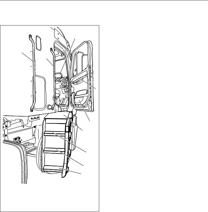
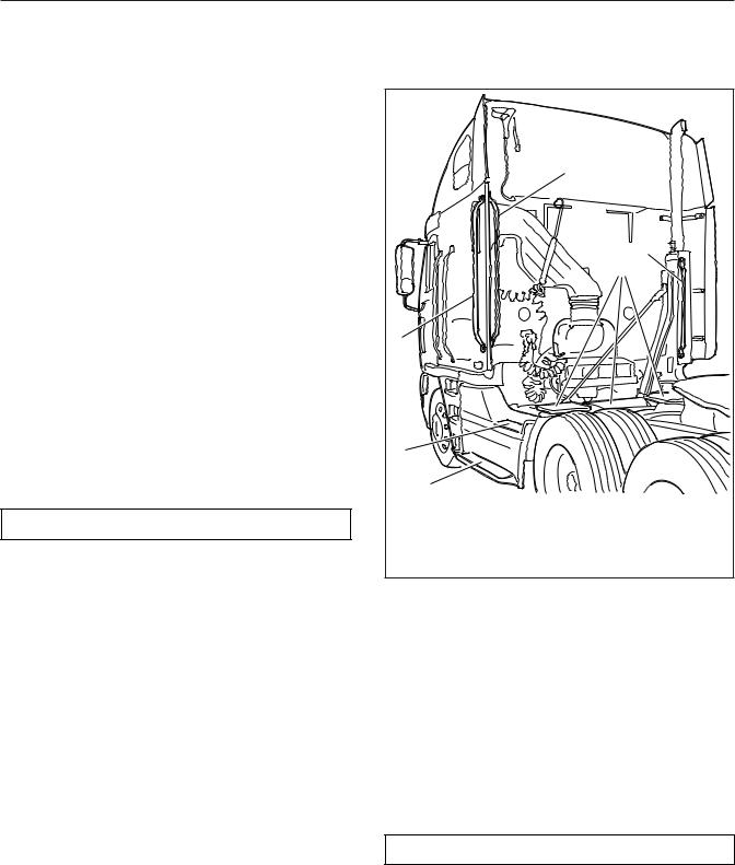
Back-of-Cab Access
Grab handles are typically located on the backwall of the cab or sleeper, or on the inside of the cab extender, if equipped. See Fig. 2.8. A grab handle may also be provided on the exhaust stack. Steps may be mounted on the fuel tank(s), battery or tool box(es), or on metal brackets secured to the frame rail. A deck plate is mounted across the top of the frame rails. All other areas are not meant to support back- of-cab access.
 WARNING
Follow these rules for back-of-cab access. Failing to follow these rules could lead to a fall, and possible personal injury.
Never step on any exterior part unless it has a slip-resistant surface meant for safe stepping. If the surface is movable, such as a battery box cover with a slip-resistant surface, be certain it is Þrmly secured.
Be careful not to trip on items such as chains or air lines in the back-of-cab area.
Always follow safety procedures for back-of-cab access, maintaining three-point contactÑboth hands and one foot, or both feet and one handÑ whenever moving around, and always face in toward the deck plate when climbing up or down.
Wet or dirty shoes, steps, or grab rails greatly increase the chance of slipping or falling. If your shoes or the contact areas are wet or dirty, clean and dry them as much as possible before accessing the back of cab area, and be especially careful when climbing or standing on the vehicle.
|
|
4 |
|
|
|
|
6 |
|
|
|
5 |
3 |
|
|
|
2 |
|
|
|
|
1 |
|
|
05/09/2012 |
|
f720752 |
|
1. |
Bottom Step |
4. |
Inboard Grab Handle |
2. |
Top Step |
5. |
Deck Plates |
3. |
Outboard Grab |
6. |
Exhaust-Mounted |
|
Handle |
|
Grab Handle |
Fig. 2.8, Back-of-Cab Access
Never jump onto, or off of, a vehicle; doing so creates a very high likelihood of a fall and personal injury.
Wet or dirty shoe soles greatly increase the chance of slipping or falling. If your soles are wet or dirty, be especially careful when accessing the back-of-cab area.
Be careful not to get hands or feet tangled in hoses or other back-of-cab equipment. Carelessness could cause a person to trip and fall, with possible injury.
Accessing Back-of-Cab Area
 WARNING
External surfaces of the exhaust system remain hot after the engine has been shut down. When accessing the back of the cab or sleeper, do not
2.7
Vehicle Access
touch any part of the exhaust system other than the exhaust-mounted grab handle, if equipped, or severe burns could occur.
1.Facing the center of the deck plate, grasp the grab handle with both hands. Reach up as far as is comfortable.
2.Place one foot on the bottom step and pull yourself up.
3.Place your other foot on the top step.
4.Move your lower hand to a higher position on the grab handle.
5.Step onto the deck plate.
Exiting the Back-of-Cab Area
1.Face the center of the vehicle and grasp the grab handle with both hands.
2.Place one foot at a time on the top step.
3.Move your upper hand to a lower position on the grab handle.
4.Move one foot to the bottom step.
5.Step to the ground with your upper foot first.
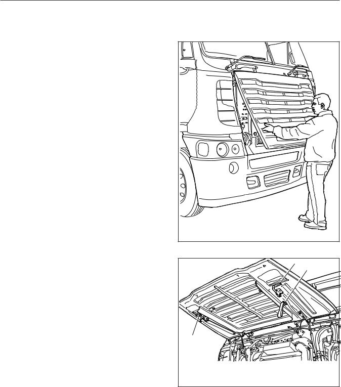
Opening the Grille

 CAUTION

Step back from the grille when opening it. The grille can open quickly and could hit a person, possibly resulting in personal injury.
Opening the grille allows the driver access to the engine oil dipstick, the coolant fill cap, and the windshield washer reservoir. To open the grille, face the front of the truck, reach through the latch access openings on either side of the grille, and release the two latches. See Fig. 2.9. Grip the grille firmly with both hands and lift. Pull the interior straps down to pull the grille shut. See Fig. 2.10.
Make sure the grille is shut and latched securely.
NOTE: On some vehicles, the access latches are located behind the lower corners of the grille.
05/23/2011 |
f602457 |
Fig. 2.9, Opening the Grille
1
A
1
05/23/2011 |
f602458 |
A. Use this strap to close the grille. 1. Grille Latches
Fig. 2.10, Grille (shown fully open)
2.8
Vehicle Access
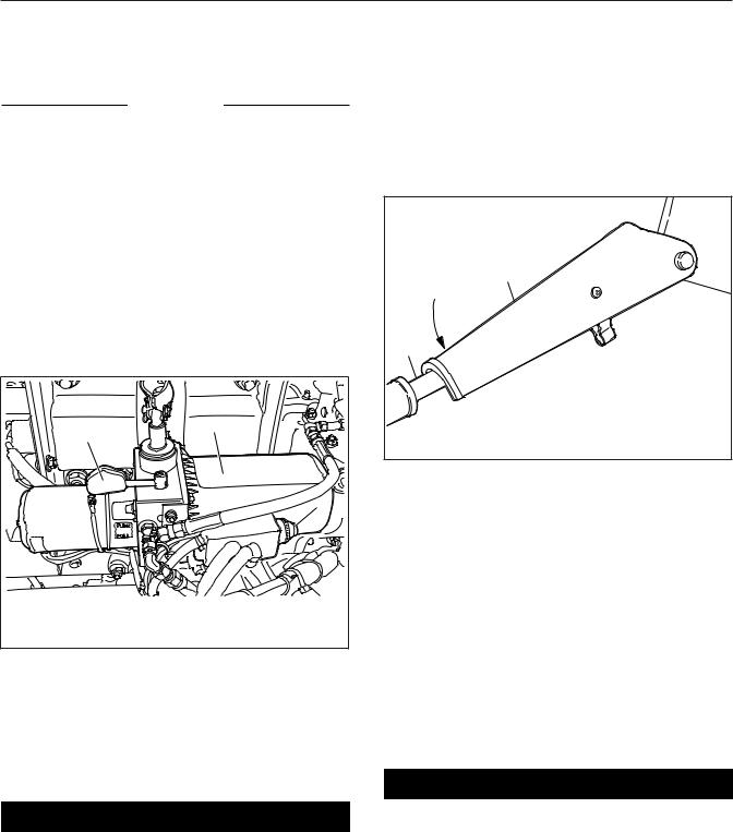
Cab Tilt System
The hydraulic tilt system is used to tilt and lower the cab. An electric motor is used to activate the hydraulic tilt pump. The tilt pump can also be operated manually if necessary. A pump handle is located in the baggage compartment for manually working the tilt pump.
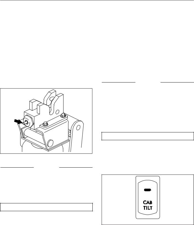
The hydraulic cab latches open automatically when the cab is tilted. When the cab is returned to the operating position, the latch hooks lock automatically. An indicator pin on the outboard side of each latch protrudes when the latch is unlocked, and recedes when the latch is locked. See Fig. 2.11.
10/19/94 |
f310441 |
Fig. 2.11, Indicator Pin
NOTICE
Do not use either the telescoping tube assembly or the hydraulic tilt cylinder as a step or handhold; you could damage the transmission, telescoping tube assembly, or the tilt cylinder.
Tilting the Cab
 WARNING
Before tilting the cab, make sure there is adequate clearance in front of the vehicle and that the area is free of people and objects.
Do not tilt the cab with the engine running. Tilting the cab could engage the transmission. If the engine is running, the vehicle could move, caus-
ing an accident that could result in personal injury or property damage.
The hydraulic tilt system is a cab-tilting, not a cab-holding device. Do not leave the vehicle unattended unless the cab is fully tilted or resting against the safety stop. Holding the cab in place with the hydraulic tilt system may result in personal injury or death and/or property damage.
IMPORTANT: Before tilting or lowering the cab, read the warning label on the tilt pump and the tilt instructions label on the exhaust stack.
NOTICE
Before tilting the cab, make sure the vehicle is parked on level ground, both side-to-side and fore-to-aft. Tilting the cab while the vehicle is parked on a slope may damage the cab mounts and prevent you from returning the cab to the operating position.
1.Park the vehicle on a level surface, place the vehicle in neutral, shut down the engine, and set the parking brake. Chock the tires.
 WARNING
Objects falling in the cab or a door ßying open could damage the vehicle or cause personal injury.
2.Secure all loose articles in the cab and bunk, then activate the tilt system power switch on the dash. See Fig. 2.12.
04/24/2012 |
f611179 |
Fig. 2.12, Cab Tilt Switch
3.Exit the cab and make sure the doors are fully latched.
2.9
Vehicle Access
NOTICE
Make sure the grille is open before tilting the cab (vehicles built from June 2011). Leaving the grille closed while tilting the vehicle will cause damage to the grille.
IMPORTANT: Vehicles built February 2012 and later are equipped with a safety mechanism that prevents the tilt pump from operating when the grille is not open.
4.Fully open the grille.
5.Check the cab travel path for obstructions.
6.Move the pump control lever to the TILT position. See Fig. 2.13.
|
1 |
|
2 |
|
|
|
|
|
|
|
3 |
05/07/2012 |
|
f602470 |
|
1. |
Pump Control Lever |
3. |
Pump Activation |
2. |
Hydraulic Tilt Pump |
|
Button |
Fig. 2.13, Cab Tilt Pump
7.Press and hold the button on the pump to disengage the hold-down latches and begin tilting the cab.
IMPORTANT: Check the indicator pin on each cab latch. The latches have disengaged if the pins are out. See Fig. 2.11.
 DANGER
Make sure the safety stop is engaged on the right tilt cylinder rod. If the safety stop isnÕt engaged, and the cab should drop, the result could be serious injury or death.
8.When the cab reaches a 30-degree angle, stop tilting the cab by letting go of the pump button. Engage the safety stop on the right tilt cylinder rod. See Fig. 2.14. The safety stop prevents the cab from accidentally dropping below this position.
|
2 |
|
|
1 |
|
|
|
04/15/93 |
|
f310357a |
|
1. |
Tilt Cylinder Rod |
2. |
Safety Stop |
Fig. 2.14, Safety Stop Engaged
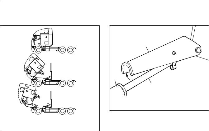
9.To tilt the cab all the way, press and hold the button on the pump until the cab nears a 45degree angle (the balance point). See Fig. 2.15. Once the cab goes beyond 45 degrees, release the button on the pump and move the tilt pump lever to the RETURN position in order to slow cab descent.
IMPORTANT: If the cab stops after it has gone beyond 45 degrees, don’t force it down with the tilt pump. The velocity fuses have locked the tilt cylinders. To unlock them, see Hydraulic Lockup, below.
Returning the Cab to Operating Position
 DANGER
Stay completely clear of the cabÕs travel path at all times. Once the safety stop has been released, donÕt lean over the frame rails, the engine, or the transmission for any reason. To do so could result in serious injury or death.
1.Move the pump lever to the RETURN position.
2.10
Vehicle Access
A
B
C
03/27/98 |
f000896 |
A.Upright or Operating Position
B.45° Tilted Position (balance position)
C.Full-Tilt Position
Fig. 2.15, Cab Tilt Positions
2.Check the cab travel path for obstructions.
3.Press and hold the button on the pump to begin moving the cab to the operating position.
NOTE: To slow the cab descent, reverse the tilt pump lever after the cab passes the balance point.
4.Allow the cab to lower to the safety stop, then move the safety stop away from the right tilt cylinder rod. See Fig. 2.16.
5.Press and hold the button on the pump until the cab nears a 45-degree angle (the balance point). See Fig. 2.15. Once the cab goes beyond 45 degrees, release the button on the pump and move the tilt pump lever to the TILT position in order to slow cab descent.
IMPORTANT: If the cab stops after it has gone beyond 45 degrees, don’t force it down with the tilt pump. The safety stop is in the locked position or, the velocity fuses have locked the tilt cylinders. Release the safety stop or, to unlock the fuses, see Hydraulic Lockup, below.
6.Move the pump lever to the RETURN position.
|
1 |
|
|
3 |
|
|
|
|
|
2 |
|
04/15/93 |
|
f310358a |
|
1. |
Safety Stop |
3. |
Tilt Cylinder |
2. |
Tilt Cylinder Rod |
|
|
Fig. 2.16, Safety Stop Disengaged
7.Check the indicator pin on each cab latch. The latches are locked when the pins have moved back into the piston and cylinder spring assembly.
NOTE: Maintain the hydraulic oil level at the oil fill plug. Add oil only when the cab is in the operating position. Use only Freightliner-approved hydraulic oil. See Group 60 of the Century Class Trucks Maintenance Manual.
8.Close the grille.
9.Switch off the tilt system dash switch.
Hydraulic Lockup
Hydraulic lockup can occur for the following reasons:
•very cold temperatures
•use of the wrong hydraulic fluid
•air in the system
•sudden cab movement
•ruptured hydraulic line
•continued pumping after the cab goes overcenter
•tilt strut in locked position while lowering the cab
2.11

Vehicle Access
Any of the above situations will lock the tilt cylinders. To unlock the cylinders, the cab must be moved in the opposite direction of travel.
For example, if the cab is moving toward the full-tilt position when the lockup occurs, move the control lever to RETURN and work the pump a few strokes to unlock the cylinders. Move the control lever to the TILT position and allow the cab to descend to a fulltilt position.
If the cab is moving toward the lowered (operating) position when the lockup occurs, move the control lever to TILT and work the pump a few strokes to unlock the cylinders. Move the control lever to RETURN and allow the cab to descend to the operating position.
2.12

3
Electrical System
Circuit Breaker/Relay Panel . . . . . . . . . . . . . . . . . . . . . . . . . . . . . . . . . . . . . . . . . . . . . . . . . . . . . . . . . 3.1 Low Voltage Disconnect Feature . . . . . . . . . . . . . . . . . . . . . . . . . . . . . . . . . . . . . . . . . . . . . . . . . . . . . 3.1 Cab Load Disconnect Switch . . . . . . . . . . . . . . . . . . . . . . . . . . . . . . . . . . . . . . . . . . . . . . . . . . . . . . . . 3.1 Battery Access . . . . . . . . . . . . . . . . . . . . . . . . . . . . . . . . . . . . . . . . . . . . . . . . . . . . . . . . . . . . . . . . . . . 3.1
Electrical System
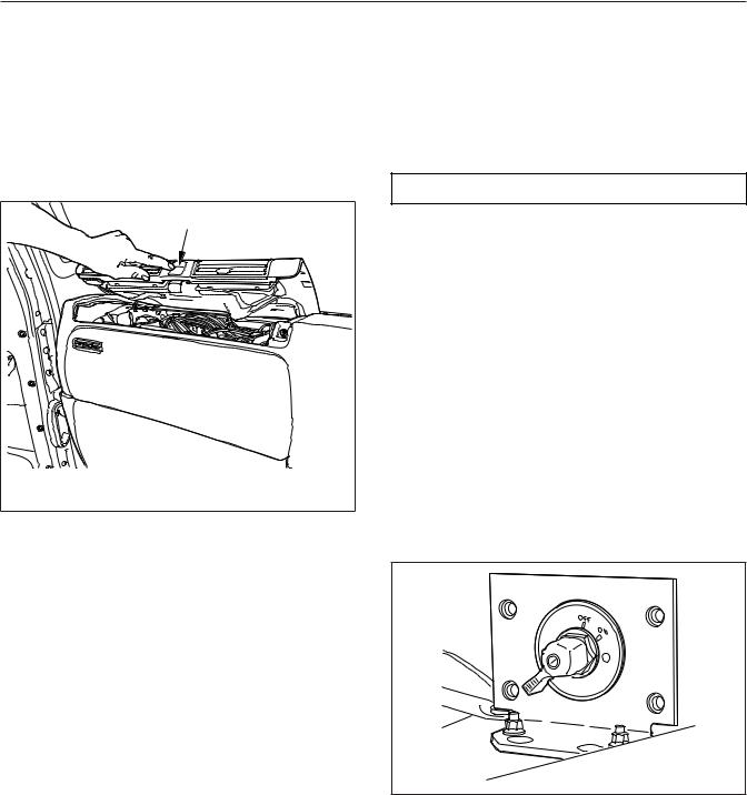
Circuit Breaker/Relay Panel
The circuit breaker/relay panel is located in the dash in front of the passenger seat. To access the compartment, press the button labeled PRESS and lift the top dash panel. See Fig. 3.1.
A |
|
05/07/2012 |
f545897 |
A. Press the button and lift the top dash panel |
|
Fig. 3.1, Circuit Breaker/Relay Panel (right-hand drive shown)
Low Voltage Disconnect
Feature
The low voltage disconnect (LVD) feature protects the batteries from excessive discharge by disconnecting certain circuits from battery power supply. This allows the batteries to maintain acceptable charge to restart the vehicle. The LVD system turns off cab and sleeper accessories when voltage drops to 12.3 volts. An alarm sounds for one minute before accessories are turned off. If no action is taken within that minute, the LVD module will shut off power to predetermined cab and sleeper circuits and illuminate an LED indicator on the LVD module located inside the right-hand door frame behind the seat. These circuits will remain off until the LVD measures 13.0 volts on the electrical system, which can be done by starting the engine. After the engine is started, the system will reset.
All vehicles equipped with LVD should have a sticker on the dash indicating the presence of the system.
Another sticker is located inside the right-hand door frame behind the seat, along with the LVD module.
Cab Load Disconnect Switch
 WARNING
Turning the cab load disconnect switch (CLDS) to the off position does not disconnect the connection between the battery and the starter. To work on the vehicle safely, the negative leads must be disconnected from the battery.
IMPORTANT: The ignition should be turned off before turning the CLDS to on or off.
The CLDS is used to avoid excessive draw on the battery when the vehicle is parked for an extended period of time by disconnecting (or opening) the connection between the battery and the most of the vehicle electrical system. See Fig. 3.2.
The CLDS may be mounted:
•inside the cab on the outboard side of the driver’s seat;
•at the battery box;
•outboard on the left frame rail.
06/19/2007 |
f545071 |
Fig. 3.2, Cab Load Disconnect Switch
Battery Access
NOTE: On vehicles with vertically-mounted mufflers, tilt the cab slightly to open the battery box.
3.1
Electrical System
The batteries are typically located aft wall of the cab/ sleeper compartment. To remove the cover from the battery box, release the latch and lift the cover.
3.2

4
Instruments
Instrumentation Control Units . . . . . . . . . . . . . . . . . . . . . . . . . . . . . . . . . . . . . . . . . . . . . . . . . . . . . . . 4.1
Warning and Indicator Lights . . . . . . . . . . . . . . . . . . . . . . . . . . . . . . . . . . . . . . . . . . . . . . . . . . . . . . . . 4.3
Instruments . . . . . . . . . . . . . . . . . . . . . . . . . . . . . . . . . . . . . . . . . . . . . . . . . . . . . . . . . . . . . . . . . . . . . . 4.7
Driver Message Center . . . . . . . . . . . . . . . . . . . . . . . . . . . . . . . . . . . . . . . . . . . . . . . . . . . . . . . . . . . 4.10
Overhead Instrument Panel . . . . . . . . . . . . . . . . . . . . . . . . . . . . . . . . . . . . . . . . . . . . . . . . . . . . . . . . 4.19
Instruments
Instrumentation Control Units
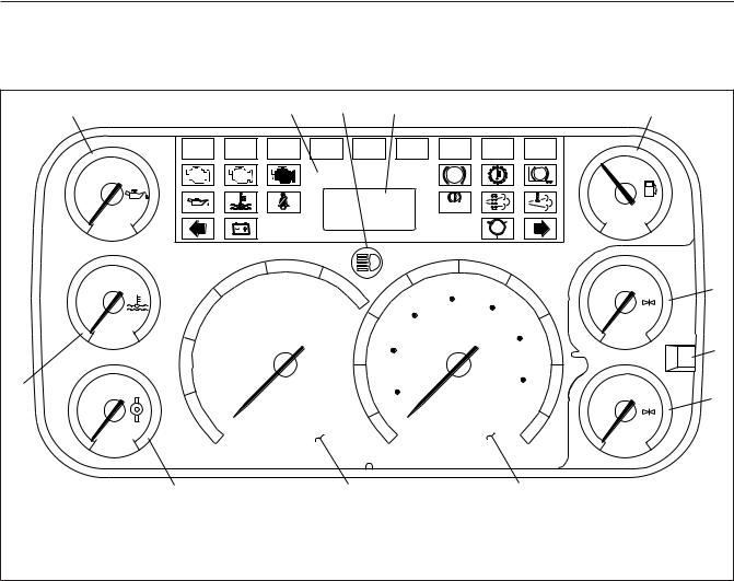
The instrumentation control unit (ICU) provides the driver with engine and vehicle information. It is comprised of standard and optional gauges, an audible warning, a driver message center, and a lightbar containing warning and indicator lamps (also known as telltales). Warning and indicator lamps illuminate in red (danger), amber (caution), green (status advisory), or blue (high-beam headlights activated).
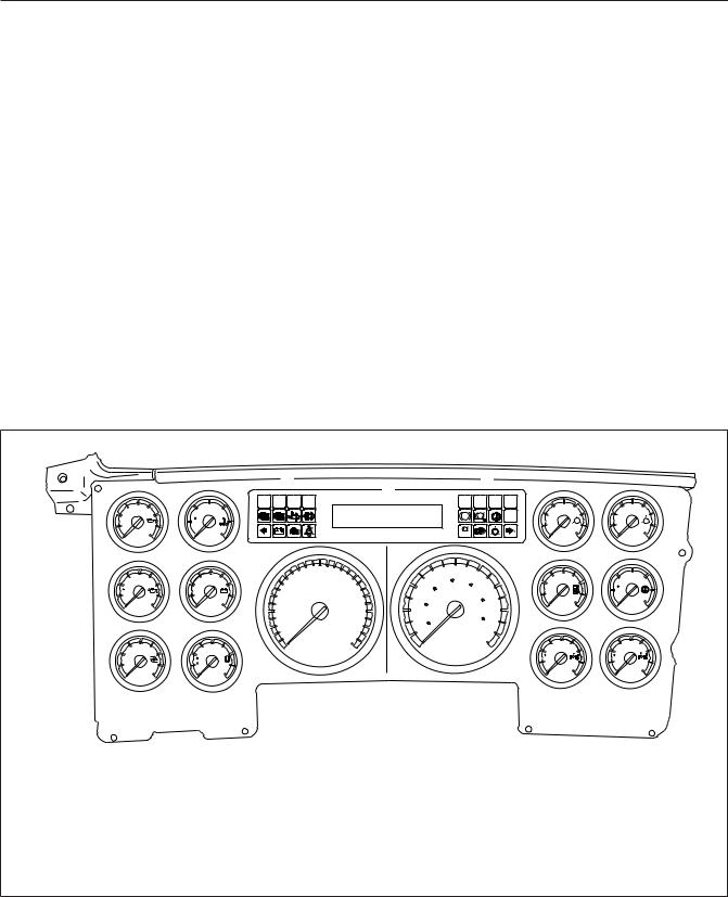
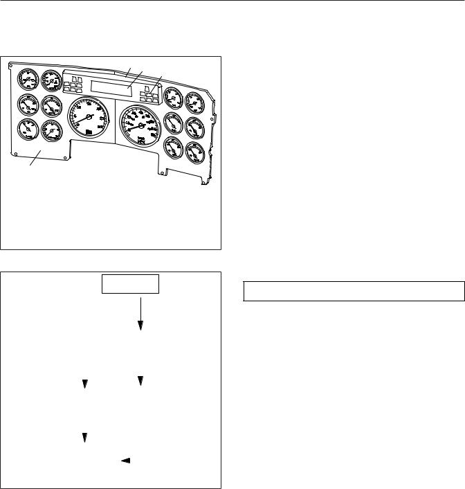
Argosy vehicles are equipped with either an ICU4M (Fig. 4.1), ICU3 (Fig. 4.2), or ICU2M (Fig. 4.3).
The following headings in this chapter provide additional information and operating instructions for ICU components:
•"Warning and Indicator Lights"
•"Instruments"
•"Driver Message Center"
Ignition Sequence
When the ignition is turned on, the ICU runs a selfcheck. See Fig. 4.4. Observing the ignition sequence is a good way to ensure the ICU is functioning properly.
IMPORTANT: Do not crank the engine until the ICU gauge sweep is complete.
NOTE: Air gauges do not complete a sweep of their dials during the ignition sequence.
When the ignition is turned on, the following actions should occur:
•electronic gauges complete a full sweep of their dials
•some warning and indicator lamps illuminate, then are extinguished
|
|
|
|
|
|
8 |
|
|
7 |
|
|
|
|
8 |
|
|
|
|
|
|
|
|
|
|
|
|
|
|
|
|
|
|
|
|
|
|
|
|
|
|
|
|
|
OPT |
OPT |
OPT |
OPT |
|
|
|
|
OPT |
OPT OPT |
OPT |
|
|
|
|
|
|
|
40 |
150 |
200 |
|
|
|
FASTEN SEATBELTS |
|
|
|
|
|
|
60 |
100 |
60 |
100 |
|
|
|
|
|
|
|
|
|
|
|
|
OPT |
||||||||
|
|
|
|
|
|
|
|
ABS |
ABS |
|
|
|
|
||||||
|
PSI |
|
F |
CHECK |
STOP |
|
|
0000432 MILES |
|
|
IDLE |
PSI |
P |
PSI |
S |
||||
|
|
|
|
|
|
|
|
|
|
|
|||||||||
|
0 |
100 |
100 |
250 |
|
|
|
|
|
|
|
|
! |
|
|
0 |
160 |
0 |
160 |
|
|
|
|
|
|
|
|
BRAKE |
|
|
|||||||||
|
|
OIL |
WATER |
|
|
|
|
|
|
|
|
|
|
AIR |
AIR |
|
|||
|
|
|
|
|
|
|
|
|
|
|
|
|
|
|
|||||
|
1 |
|
2 |
|
|
|
|
|
|
|
|
|
|
|
|
11 |
|
12 |
|
|
|
200 |
|
12 |
|
10 |
15 |
20 |
|
35 |
45 |
55 |
|
|
1/2 |
|
|
||
|
|
|
|
RPM |
|
|
|
|
|
190 |
270 |
||||||||
|
|
|
|
|
|
|
|
|
|
||||||||||
|
|
|
|
|
|
25 |
|
70 |
|
|
65 |
|
|
|
|||||
|
F |
|
|
|
|
X 100 |
50 |
|
90 |
|
|
|
F |
|
|||||
|
|
|
|
|
|
|
|
|
|
|
E |
F |
110 |
350 |
|||||
|
100 |
300 |
8 |
16 |
|
|
|
|
|
|
|
|
110 |
|
|||||
|
|
|
|
|
|
30 |
|
|
|
FUEL |
TRANS |
||||||||
|
|
OIL |
VOLTS |
5 |
|
|
25 |
15 |
|
|
|
75 |
|
||||||
|
3 |
4 |
|
|
|
|
|
|
|
13 |
|
14 |
|
||||||
|
|
|
|
|
|
|
|
10 |
|
|
130 |
|
|
|
|||||
|
|
|
|
|
|
|
5 |
|
|
|
85 |
|
|
|
|||||
|
|
|
|
|
|
0 |
|
30 |
|
|
|
|
|
|
|
|
|
||
|
|
40 |
|
|
|
|
|
|
|
|
|
|
|
200 |
200 |
|
|||
|
|
|
90 |
|
|
|
|
MPH |
|
|
|
km/h |
|
|
|||||
|
|
|
|
|
|
|
|
|
|
|
|
|
|
|
|||||
|
PSI |
|
F |
|
|
|
|
|
|
|
|
|
|
|
|
F |
|
F |
|
|
|
|
10 |
|
9 |
|
|
|
10 |
|
|
|
|
|
|
100 |
300 |
100 |
300 |
|
0 |
80 |
30 |
150 |
|
|
|
|
|
|
|
|
|
||||||
|
|
|
|
|
|
|
|
|
|
AXLE |
AXLE |
||||||||
|
|
TURBO |
|
PYRO |
|
|
|
|
|
|
|
|
|
|
|
|
|
||
|
5 |
|
6 |
|
|
|
|
|
|
|
|
|
|
|
|
15 |
|
16 |
|
09/29/2010 |
|
|
|
|
|
|
|
|
|
|
|
|
|
|
|
|
|
f610706b |
|
1. Engine Oil Pressure Gauge |
|
|
|
|
9. |
Tachometer |
|
|
|
|
|
|
|
||||||
2. Engine Coolant Temperature Gauge |
|
|
|
10. Speedometer |
|
|
|
|
|
||||||||||
3. Engine Oil Temperature Gauge |
|
|
|
11. Primary Air Pressure Gauge |
|
|
|
||||||||||||
4. |
Battery Voltage Gauge |
|
|
|
|
|
12. Secondary Air Pressure Gauge |
|
|
||||||||||
5. Turbo Boost Air Pressure Gauge |
|
|
|
13. Fuel Level Gauge |
|
|
|
|
|
||||||||||
6. |
Pyrometer |
|
|
|
|
|
|
14. Transmission Fluid Temperature Gauge |
|
||||||||||
7. |
Driver Message Center |
|
|
|
|
|
15. Forward Drive Axle Temperature Gauge |
|
|||||||||||
8. |
Warning and Indicator Lights |
|
|
|
|
16. Rearmost Drive Axle Temperature Gauge |
|
||||||||||||
Fig. 4.1, ICU4M Instrument Cluster (typical)
4.1
|
|
|
|
|
|
|
|
|
|
|
|
|
|
Instruments |
||
|
1 |
|
|
|
|
2 |
3 |
|
4 |
|
|
|
|
|
5 |
|
|
|
|
OPT |
OPT |
|
OPT |
OPT |
OPT |
|
OPT |
OPT |
OPT |
OPT |
|
|
|
|
|
50 |
|
|
|
|
|
|
|
|
ABS |
|
ABS |
|
1/2 |
|
|
|
|
CHECK |
STOP |
|
|
|
|
|
|
|
|
|
|
||
|
PSI |
|
|
|
|
|
|
|
|
|
|
|
|
|
|
|
|
0 |
100 |
|
|
|
|
|
|
|
|
BRAKE |
|
|
E |
F |
|
|
|
|
|
|
|
|
|
|
|
|
|
|
||||
|
OIL |
|
|
|
|
|
|
|
|
|
|
|
FUEL |
|
||
|
150 |
200 |
|
|
20 |
25 |
|
|
35 |
45 |
55 |
|
50 |
100 |
6 |
|
|
F° |
|
|
15 |
|
|
|
PSI |
|
|||||||
|
|
|
|
|
30 |
|
|
70 |
|
|
|
|||||
|
|
|
|
|
|
25 |
50 |
90 |
65 |
|
|
|
||||
|
100 |
250 |
|
|
|
|
|
0 |
150 |
|
||||||
|
10 |
|
|
|
|
|
|
|
||||||||
|
WATER |
|
|
|
|
|
|
|
|
110 |
|
|
AIR |
7 |
||
|
|
|
|
|
|
|
15 |
30 |
|
|
|
PUSH− |
||||
|
|
|
|
|
|
|
|
|
|
75 |
|
MODE |
|
|||
|
|
|
|
|
|
|
|
|
|
|
|
|
HOLD− |
|
||
|
|
|
|
|
|
|
|
|
|
|
|
|
RESET |
|
||
|
|
|
|
|
|
|
|
|
|
|
|
|
|
|
||
12 |
|
225 |
5 |
|
|
|
|
|
|
10 |
|
130 |
50 |
100 |
|
|
|
|
|
|
|
|
5 |
|
|
|
85 |
8 |
|||||
|
|
|
|
|
|
|
|
|
|
|
|
|
|
|||
|
F° |
|
|
0 |
RPM |
|
|
|
km/h |
|
PSI |
|
|
|||
|
|
|
|
|
|
|
|
|
|
|
|
|
||||
|
100 |
350 |
|
X100 |
|
|
|
|
MPH |
|
|
0 |
150 |
|
||
|
TRANS |
|
|
|
|
|
|
|
|
|
||||||
|
|
|
|
|
|
|
|
|
|
|
|
|
AIR |
|
||
10/26/2006 |
|
11 |
|
|
|
10 |
|
|
|
|
9 |
|
f610837b |
|||
1. Engine Oil Pressure Gauge |
|
6. |
Primary Air Pressure Gauge |
|
10. Tachometer |
|
|
|||||||||
2. |
Lightbar |
|
|
|
7. |
Mode/Reset Switch |
|
|
|
11. Tranismission Fluid Temperature |
|
|||||
3. |
Headlight High-Beam Indicator |
|
8. |
Secondary Air Pressure Gauge |
|
Gauge |
|
|
|
|||||||
4. |
Driver Message Center |
|
|
9. |
Speedometer |
|
|
|
|
12. Coolant Temperature Gauge |
|
|||||
5. |
Fuel Level Gauge |
|
|
|
|
|
|
|
|
|
|
|
|
|
|
|
Fig. 4.2, ICU3 Instrument Cluster
•audible alert sounds until sufficient air pressure builds up in the primary and secondary air systems
•software revision level of the ICU is displayed on the driver message center, followed by any active faults
IMPORTANT: If any red or amber warning or indicator lamps do not illuminate during the ICU self-check or do not extinguish after the selfcheck completes, take the action outlined in Table 4.1, or take the vehicle to an authorized Daimler Trucks service facility as soon as possible.
NOTE: If active faults are present, take the vehicle to an authorized Daimler Trucks service facility as soon as possible.
If the ICU receives active fault codes, it displays them one after the other until the parking brake is released or the ignition is turned off. Once the parking brake is completely released, the ICU displays the odometer. If there are no active faults, the ICU displays the odometer after the self-check completes.
When the self-check is complete on an ICU4M, the fasten seat belt screen displays if the engine is off. If the engine is running, the idle hours screen displays.
Audible Alerts
An audible alert sounds during the ignition sequence and whenever one of the following conditions exists:
•Engine oil pressure falls below the minimum preset value.
•Coolant temperature rises above the maximum preset value.
4.2
Instruments
|
2 |
3 |
|
|
4 |
|
1 |
|
09/27/95 |
f600991 |
|
1. |
Main Dash Panel |
|
2. |
Lightbar |
|
3. |
Driver Message Center |
|
4. |
Warning and Indicator Lights |
|
Fig. 4.3, ICU2M Instrument Cluster (typical)
IGNITION SWITCH
TURNED TO ON
|
|
|
|
|
|
ICU PERFORMS |
|
|||
|
|
|
|
|
|
|
SELF−TEST |
|
||
|
|
|
|
|
|
|
|
|
|
|
IF NO FAULTS |
|
|
|
|
|
IF FAULT DETECTED |
||||
|
|
|
|
|
||||||
WERE DETECTED |
|
|
|
|
|
|
|
|
||
|
|
|
|
|
|
|
|
|
|
|
|
|
|
|
|
|
|
|
|
|
|
|
|
|
|
|
|
|
APU 190 |
|
||
|
123456.7 |
|
|
|
|
|||||
|
|
|
|
|
|
|
|
|||
|
|
|
MI |
|
|
|
|
|
|
|
|
|
|
|
|
|
|
|
|
|
|
|
12.3 VOLTS |
|
|
|
|
|
|
|
||
|
|
|
|
|
|
|
|
|
||
|
|
|
|
|
|
|
|
|
|
|
|
|
|
|
|
|
|
|
|
|
|
PARKING BRAKE |
|
|
|
|
PARKING BRAKE |
|||||
RELEASED |
|
|
|
|
RELEASED |
|||||
|
|
|
|
|
|
|
|
|||
|
123456.7 |
|
|
|
|
|
|
|
||
|
|
|
MI |
|
|
|
|
|
|
|
|
|
|
|
|
|
|
|
|
|
|
|
12.3 VOLTS |
|
|
|
|
|
|
|
||
01/18/2012 |
|
|
|
|
|
|
|
|
|
f040420c |
Fig. 4.4, ICU Self-Check
•Air pressure falls below approximately 70 psi (483 kPa).
•Parking brake is set with the vehicle moving faster than two miles per hour.
•System voltage falls below 12 volts.
•Door is open or the headlights are on, with the parking brake off.
Warning and Indicator Lights
The ICU lightbar has three or four rows of warning and indicator lights with icon symbols, depending on the ICU. The positions of the lights may vary for the different ICU’s, but the telltales are standard for all applications. See Table 4.1 for a listing of standard and commonly used warning and indicator lamps.
Warning and indicator lamps illuminate in red (danger), amber (caution), green (status advisory), or blue (high-beam headlights active).
IMPORTANT: Depending upon local jurisdictional emissions guidelines, vehicles may not be equipped with all of the lamps shown in
Table 4.1.
Engine Protection System
 WARNING
When the red STOP engine lamp illuminates, most engines are programmed to shut down automatically within 30 seconds. The driver must immediately move the vehicle to a safe location at the side of the road to prevent causing a hazardous situation that could cause bodily injury, property damage, or severe damage to the engine.
See Fig. 4.5 for an explanation of the aftertreatment system (ATS) warning indicators, and actions required to avoid further engine protection steps.
The STOP engine lamp illuminates when the engine protection system is activated in one of two ways. On some engines, the engine protection system will derate the engine, allowing it to run at lower rpm and slower vehicle speed. Drive the vehicle to a safe location or to a service facility.
IMPORTANT: Safely bring the vehicle to a stop on the side of the road and shut down the engine as soon as the red light is seen. If the engine shuts down while the vehicle is in a hazardous location, turn the key to the OFF position for a few seconds, then restart the engine and move the vehicle to a safer location.
4.3
Instruments
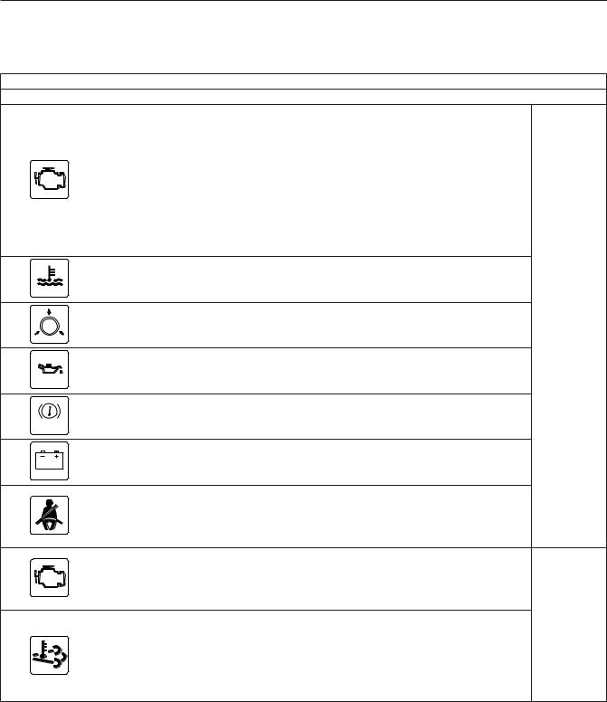
Common Warning and Indicator Lamps
Lamp Description Color
Indicates a serious fault that requires engine shutdown immediately. The engine protection system will reduce the maximum engine torque and speed, and, if the condition does not improve, will shut down the engine within 30 to 60 seconds.
STOP |
STOP Engine* |
Safely bring the vehicle to a stop on the side of the road |
|
|
and shut down the engine as soon as the red light is seen. |
IMPORTANT: If the engine shuts down while the vehicle is in a hazardous location, turn the key to the OFF position for a few seconds, then restart the engine and move the vehicle to a safer location.
Indicates the coolant temperature is above the maximum
High Coolant Temperature allowable temperature.
|
Low Air Pressure |
Indicates air pressure in the primary or secondary reservoir |
Red |
|
is below 70 psi (483 kPa). |
||
|
|
|
|
|
Low Engine Oil Pressure |
Indicates the engine oil pressure is below the minimum |
|
|
allowable pressure. |
|
|
|
|
|
|
|
|
Indicates the parking brake is engaged. An audible alert |
|
BRAKE |
Parking Brake |
activates when the vehicle is moving over 2 mph (3 km/h) |
|
|
with the parking brake set. |
|
|
|
|
|
|
|
Low Battery Voltage |
Indicates that battery voltage is 11.9 volts or less. |
|
|
|
Activates with an audible alert when the system detects that |
|
|
|
the parking brake is off and the driver seat belt is not |
|
|
Unfastened Seat Belt |
fastened on some vehicles. On other vehicles, this lamp |
|
|
|
illuminates for 15 seconds when the ignition is first turned |
|
|
|
on. |
|
|
|
Indicates an engine condition (low oil pressure, low coolant |
|
|
CHECK Engine* |
level, high coolant temperature, high DPF soot level, or |
|
CHECK |
uncontrolled DPF regeneration) that requires correction. |
|
|
|
|
Correct the condition as soon as possible. If the condition |
|
|
|
worsens, the STOP engine lamp will illuminate. |
|
|
|
Slow (10-second) flashing indicates a regeneration (regen) |
Amber |
|
|
is in progress. |
|
|
|
|
|
|
High Exhaust System |
IMPORTANT: When the HEST lamp is illuminated, do |
|
|
Temperature (HEST)* |
not park the vehicle near ßammable material. |
|
|
|
Solid illumination indicates high exhaust temperatures at the |
|
|
|
outlet of the tail pipe when speed is below 5 mph (8 km/h). |
|
4.4
Instruments
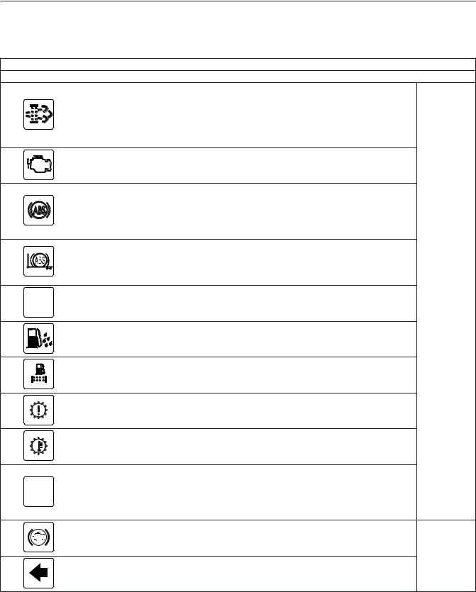
Common Warning and Indicator Lamps
|
|
Lamp Description |
Color |
|
|
|
Solid illumination indicates a regen is required. Change to a |
|
|
|
|
more challenging duty cycle (such as highway driving ) to |
|
|
|
Diesel Particulate Filter |
raise exhaust temperatures for at least twenty minutes, or |
|
|
|
perform a parked regen. |
|
||
|
(DPF) Status |
|
||
|
|
|
||
|
|
Blinking indicates that a parked regen is required |
|
|
|
|
immediately. An engine derate and shutdown will occur. |
|
|
|
Malfunction Indicator |
Indicates an emissions-related fault. See the engine |
|
|
|
Lamp (MIL) |
operation manual for details. |
|
|
|
|
Momentary illumination indicates the vehicle ABS is |
|
|
|
|
engaged. |
|
|
|
Vehicle ABS |
Solid illumination indicates a problem with the vehicle ABS. |
|
|
|
|
|
||
|
|
Repair the ABS immediately to ensure full braking |
|
|
|
|
capability. |
|
|
|
|
Momentary illumination indicates the trailer ABS is engaged. |
|
|
|
Trailer ABS |
Solid illumination indicates a problem with the trailer ABS. |
|
|
|
|
Repair the ABS immediately to ensure full braking |
|
|
|
|
capability. |
|
|
NO |
No Charge |
Indicates the alternator is not properly powering the |
Amber |
|
CHARGE |
electrical system. |
|||
|
|
Water in Fuel
Indicates the fuel may contain water. Drain any water collected in the fuel/water separators.
|
Fuel Filter Restriction |
Indicates the fuel filter is clogged and requires service. |
|
|
Check Transmission |
Indicates an undesirable transmission condition. |
|
|
Transmission Overheat |
Indicates high transmission temperature. |
|
|
|
Flashing indicates the ATC system is active, or the ATC |
|
WHEEL |
|
button has been pressed to allow wheel slip. |
|
Wheel Spin |
Solid illumination indicates a problem with the ATC system. |
||
SPIN |
|||
|
|||
|
|
Repair the ATC system immediately to ensure full braking |
|
|
|
capability. |
|
|
Engine Brake |
Indicates the engine brake is enabled. |
Green
Left-Turn Signal
Flashing indicates the outside left-turn signal lights are activated.
4.5
Instruments
Common Warning and Indicator Lamps
|
|
|
|
|
|
|
Lamp Description |
Color |
|
|
|
|
|
|
Right-Turn Signal |
Flashing indicates the outside right-turn signal lights are |
Green |
|
|
|
|
|
|
activated. |
||
|
|
|
|
|
|
|
|
|
|
|
|
|
|
|
|
|
|
|
|
|
|
|
|
|
|
|
|
|
|
|
|
|
High-Beam Headlights |
Indicates the high-beam headlights are on. |
Blue |
|
|
|
|
|
|
|||
|
|
|
|
|
|
|||
|
|
|
|
|
|
|||
|
|
|
|
|
|
|||
|
|
|
|
|
|
|||
|
|
|
|
|
|
|||
|
|
|
|
|
|
|||
|
|
|
|
|
|
|||
|
|
|
|
|
|
|
|
|
|
|
|
|
|
|
|
|
|
|
|
|
|
|
|
|
|
|
|
|
|
|
|
|
|
|
|
* See Fig. 4.5 for an explanation of the aftertreatment system (ATS) warning indicators, and actions required to avoid further engine protection steps.
Table 4.1, Common Warning and Indicator Lamps
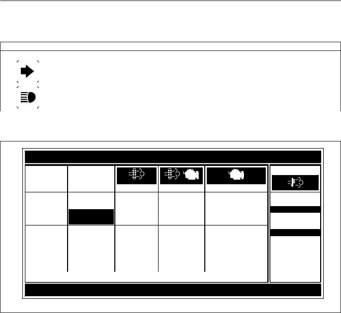
EXHAUST AFTERTREATMENT SYSTEM INFORMATION
INDICATOR |
|
|
|
|
|
CHECK |
|
STOP |
|
LAMP(S) |
|
|
|
|
|
|
|||
(Solid) |
|
|
(Flashing) |
|
(Flashing) |
|
|
||
|
|
|
|
|
|
|
|||
|
|
Level 1 |
|
|
Level 2 |
|
Level 3 |
|
Level 4 |
Indicator Lamp |
Filter Regeneration |
|
|
Filter |
|
Parked Regeneration |
|
Service Regeneration Required. |
|
Message(s) |
Recommended. |
|
|
Regeneration |
|
Required − Engine |
|
Engine Derate To Idle Only. |
|
|
|
|
|
|
Necessary |
|
Derate |
|
|
|
|
|
|
|
|
|
|
|
|
Diesel Particulate |
|
Filter is reaching |
|
|
Filter is now |
|
Filter has reached |
|
Filter has exceeded maximum |
Filter Condition |
|
capacity. |
|
|
reaching maximum |
|
maximum capacity. |
|
capacity. |
|
|
|
|
|
capacitySwitch. . |
|
|
|
|
Required Action |
Bring vehicle to |
|
|
To avoid engine |
|
Vehicle must be |
|
Vehicle must be parked, and a |
|
|
|
highway speeds to |
|
|
derate, bring vehicle |
|
parked, and a Parked |
|
Service Regeneration must be |
|
|
allow for an |
|
|
to highway speeds |
|
Regeneration must |
|
performed. Check engine |
|
|
Automatic |
|
|
to allow for an |
|
be performed. |
|
operator’s manual for details. |
|
|
Regeneration or |
|
|
Automatic |
|
Engine will begin |
|
Engine will shut down. |
|
|
perform a Parked |
|
|
Regeneration, or |
|
derate. |
|
|
|
|
Regeneration. |
|
|
perform a Parked |
|
|
|
|
|
|
|
|
|
Regeneration as |
|
|
|
|
|
|
|
|
|
soon as possible. |
|
|
|
|
 WARNING
HEST (High Exhaust
System Temperature)
Flashing
A regeneration is in progress.
Solid
Exhaust components and exhaust gas are at high temperature. When stationary, keep away from people and flammable materials or vapors.
For a driver performed Parked Regeneration, vehicle must be equipped with a dash mounted Regeneration Switch.
02/20/2009 |
f080156 |
Fig. 4.5, ATS Warning Lamps
On other engines, the engine protection system will shut down the engine. It will first derate the engine, then shut it down completely 30 to 60 seconds after the indicator illuminates (depending on the critical fault type) if the condition does not improve. Bring the vehicle to a stop on the side of the road before the engine shuts down.
Some vehicles may have a shutdown-override switch, which may be used to momentarily override the shutdown sequence. See Chapter 10 for detailed information regarding the shutdown process.
IMPORTANT: Do not attempt to restart the engine while the vehicle is moving. Bring the vehicle to a safe stop, then restart the engine.
To restart the engine, turn the ignition switch to OFF for a few seconds, then turn the ignition switch to ON and let the gauge sweep complete before starting the engine. The engine will run for a short period and shut down again if the condition does not improve.
4.6
Instruments
Instruments
Standard instruments are present on every vehicle. Optional instruments, typically located on the auxiliary dash panel or right-hand control panel, are not found on every vehicle. Instruments are listed here in alphabetical order to make the information easier to find.
Air Intake Restriction Gauge
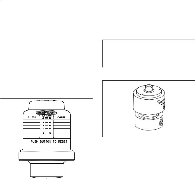
The air intake restriction gauge indicates the vacuum on the engine side of the air cleaner. On standard installations, it is mounted on the air cleaner. As an option for easier viewing, an air intake restriction indicator (see Fig. 4.6) can be mounted on the auxiliary dash panel.
10/10/2001 |
f610568 |
Fig. 4.6, Air Intake Restriction Indicator
NOTE: Rain or snow can wet the filter and cause a temporary high reading.
Air intake restriction vacuum is measured in inches of water (inH2O). For vehicles equipped with a graduated indicator or a restriction gauge on the dash, check the gauge with the engine off. If the yellow signal stays locked in the red zone once the engine is shut down, or is at or above the values shown in Table 4.2, the air cleaner element needs to be replaced.
Vehicles may be equipped with a go/no-go restriction indicator without graduations (see Fig. 4.7) instead of a graduated indicator.
Air Intake Maximum Restriction Values (inH2O)
Engine Make |
Pre-EPA07 (ADR |
EPA07 (ADR 80/ |
|
80/02) Engines |
03) Engines |
||
|
|||
Cummins |
25 |
25 |
|
Detroit |
20 |
22 |
|
Mercedes-Benz |
22 |
22 |
Table 4.2, Air Intake Maximum Restriction Values
04/08/2005 |
f090431 |
Fig. 4.7, Manual-Reset Air Restriction Indicator, Go/
No-Go
If air restriction exceeds the maximum allowable value, operate the vehicle for one more day, making sure not to run the engine over rated rpm. Refer to the engine operation manual for more information on rated rpm for your engine.
If air restriction exceeds the maximum value again, replace the air cleaner. For instructions, refer to
Group 09 of the Century Class Trucks Workshop Manual.
Application Air Pressure Gauge
An application air pressure gauge registers the air pressure being used to apply the brakes, and should be used for reference only. The gauge will not register air pressure until the foot brake pedal is depressed or the trailer hand brake is applied.
4.7

Instruments
Coolant Temperature Gauge
NOTICE
A sudden increase in coolant temperature may indicate engine or cooling system failure. Bring the vehicle to a safe stop and investigate the cause to prevent further damage. Do not operate the engine until the cause has been determined and corrected.
During normal engine operation, the coolant temperature gauge should read 175 to 195°F (79 to 91°C). If the temperature remains below 160°F (71°C), inspect the cooling system to determine the cause.
If coolant temperature rises above the maximum temperature listed in Table 4.3, the CHECK engine lamp will illuminate. If the condition does not improve, the STOP engine lamp will also illuminate and an audible warning will sound. The engine will then derate or shut down, depending on the type of engine protection system installed.
Maximum Coolant Temperature
Engine Make |
Temperature: ¡F (¡C) |
Cummins |
225 (107) |
Detroit |
215 (101) |
Mercedes-Benz |
221 (105) |
Table 4.3, Maximum Coolant Temperature
Drive Axle Oil Temperature Gauges
NOTICE
A sudden increase in oil temperature that is not caused by a load increase may indicate mechanical failure. Bring the vehicle to a safe stop and investigate the cause to prevent further damage. Do not operate the vehicle until the cause has been determined and corrected.
During normal operation, drive axle oil temperature gauges should read as follows:
•160 to 220°F (71 to 104°C) for Detroit™ and Meritor™ drive axles
•180 to 200°F (82 to 93°C) for Dana Spicer® drive axles
Under heavy loads, such as when climbing steep grades, temperatures that exceed the normal oil temperature range for a short period are not unusual. If the temperature returns to normal when the load decreases, there is no problem.
Engine Oil Pressure Gauge
NOTICE
A sudden decrease or absence of oil pressure may indicate mechanical failure. Bring the vehicle to a safe stop and investigate the cause to prevent further damage. Do not operate the engine until the cause has been determined and corrected.
The engine oil pressure gauge displays the current engine oil pressure. If engine oil pressure falls below the minimum levels shown in Table 4.4, the CHECK engine lamp will illuminate. If the condition does not improve, the STOP engine lamp will also illuminate and an audible warning will sound. The engine will then derate or shut down, depending on the type of engine protection system installed.
Minimum Oil Pressure*
Engine Model |
At Idle Speed: |
At Rated RPM: |
|
psi (kPa) |
psi (kPa) |
||
|
|||
Cummins |
15 (103) |
35 (241) |
|
Detroit |
14 (97) |
55 (350) |
|
Mercedes-Benz |
7 (50) |
36 (250) |
* Oil pressures are given with the engine at operating temperature. With the engine cold, oil pressure may be higher. Individual engines may vary from the listed pressures; observe and record pressures when the engine is new to create a guide for checking engine condition.
Table 4.4, Minimum Engine Oil Pressure
Engine Oil Temperature Gauge
NOTICE
A sudden increase in oil temperature that is not caused by a load increase may indicate mechanical failure. Bring the vehicle to a safe stop and investigate the cause to prevent further damage. Do not operate the engine until the cause has been determined and corrected.
During normal operation, the optional engine oil temperature gauge should read:
4.8
 Loading...