


Freightliner AMT3 and Mercedes-Benz Automated-Manual |
26.03 |
Transmissions |
General Troubleshooting
IMPORTANT: Always use ServiceLink when attempting to diagnose problems with the AGS (Automated Gear Shift) transmission.
How To Start
To gain a baseline for troubleshooting when there is no de®nite problem, when the malfunction is erratic or intermittent, or to determine the general health of the electrical system, start with the electrical pre-test in Subject 301.
In a few cases there will be a de®nite problem and no J1587 fault code will be sent (engine will not crank, no information on gear display, ¯uid level fault). For these problems, see the appropriate table in Subject 301.
But in most cases, the J1587 fault code is the starting point for the troubleshooting procedures. See Table 1 to ®nd information for SID fault codes. See Table 2 to ®nd information for PID fault codes.
Before starting any procedures, use ServiceLink to depressurize the AGS hydraulic system. For detailed procedures, see Subject 160.
Fault Code Guide
To troubleshoot a given fault code, look up the subject number in Table 1 (for SIDs) and Table 2 (for PIDs). Follow the procedures for that fault code until the fault is corrected.
Fault Code Guide (MID 130 SIDs)
SID |
FMI |
Text Message |
Failure Reason |
Procedure |
|
|
|
|
|
|
|
18 |
02 |
Prim Selector Erratic |
The shift lever does not shift gears. |
See Subject 302. |
|
|
|
|
|
|
|
33 |
03 |
MultiPress Ind Short Hi |
The hydraulic pressure sensor circuit is shorted to power. |
See Subject 303. |
|
|
|
|
|
|
|
33 |
04 |
MultiPress Ind Short Lo |
The hydraulic pressure sensor circuit is shorted to ground. |
See Subject 303. |
|
|
|
|
|
|
|
33 |
05 |
MultiPress Ind OPEN |
The hydraulic pressure sensor circuit is open. |
See Subject 303. |
|
|
|
|
|
|
|
52 |
05 |
Hydraulic Sys OPEN |
The hydraulic pump circuit is open. |
See Subject 304. |
|
|
|
|
|
|
|
52 |
07 |
Hydraulic Sys NoRESPONSE |
The hydraulic pressure does not increase even though the |
See Subject 304. |
|
hydraulic pump is activated. |
|||||
|
|
|
|
||
|
|
|
|
|
|
52 |
11 |
Clutch Act Not Known |
The hydraulic pump temperature is too high. |
See Subject 304. |
|
|
|
|
|
|
|
55 |
00 |
Clutch Act HIGH |
The clutch is too hot. |
See Subject 305. |
|
|
|
|
|
|
|
55 |
07 |
Clutch Act NoRESPONSE |
The clutch does not operate properly. |
See Subject 305. |
|
|
|
|
|
|
|
55 |
13 |
Clutch Act Calibrate |
The clutch needs to be calibrated. |
See Subject 305. |
|
|
|
|
|
|
|
231 |
02 |
SAE J1939 Datalink Erratic |
The J1939 datalink is not communicating properly. |
See Subject 306. |
|
|
|
|
|
|
|
231 |
09 |
SAE J1939 Datalink UPDATE |
The J1939 datalink has timed out. |
See Subject 306. |
|
|
|
|
|
|
|
231 |
12 |
SAE J1939 Datalink Bad |
The J1939 datalink is not communicating with the |
See Subject 306. |
|
transmission. |
|||||
|
|
|
|
||
|
|
|
|
|
|
251 |
00 |
POWER SUPPLY HIGH |
The power supply voltage is too high. |
See Subject 307. |
|
|
|
|
|
|
|
251 |
01 |
POWER SUPPLY Low |
The power supply voltage is too low. |
See Subject 307. |
|
|
|
|
|
|
|
251 |
05 |
POWER SUPPLY OPEN |
There is no power to the transmission with the engine |
See Subject 307. |
|
running. |
|||||
|
|
|
|
||
|
|
|
|
|
|
251 |
14 |
POWER SUPPLY RSRVD |
The power supply is not properly grounded. |
See Subject 307. |
|
|
|
|
|
|
|
253 |
02 |
Calibration Memory Erratic |
The transmission needs to be recalibrated. |
See Subject 308. |
|
|
|
|
|
|
|
253 |
12 |
Calibration Memory Bad |
The transmission needs to be recalibrated. |
See Subject 308. |
|
|
|
|
|
|
|
253 |
13 |
Calibration Memory Calibrate |
The transmission needs to be recalibrated. |
See Subject 308. |
|
|
|
|
|
|
|
253 |
14 |
Calibration Memory RSRVD |
The transmission needs to be recalibrated. |
See Subject 308. |
Business Class M2 Workshop Manual, Supplement 20, September 2011 |
300/1 |

Freightliner AMT3 |
and Mercedes-Benz Automated-Manual |
|
26.03 |
Transmissions |
|
General Troubleshooting |
|
|
Fault Code Guide (MID 130 SIDs)
SID |
FMI |
Text Message |
|
Failure Reason |
Procedure |
|
|
|
|
|
|
|
|
254 |
04 |
Controller Short Lo |
|
The TCU is shorted to ground. |
See Subject 309. |
|
|
|
|
|
|
|
|
254 |
05 |
Controller OPEN |
|
The TCU has an open circuit. |
See Subject 309. |
|
|
|
|
|
|
|
|
254 |
11 |
Controller Not Known |
|
The TCU AUTO mode software module has an error. |
See Subject 309. |
|
|
|
|
|
|
|
|
254 |
12 |
Controller Bad |
|
The TCU has a hardware problem. |
See Subject 309. |
|
|
|
|
|
|
|
|
254 |
13 |
Controller Calibrate |
|
The TCU has a software memory problem. |
See Subject 309. |
|
|
|
|
|
Table 1, Fault Code Guide (SIDs) |
|
|
|
|
|
|
|
|
|
|
|
|
|
Fault Code Guide (MID 130 PIDs) |
|
|
|
|
|
|
|
|
|
PID |
FMI |
Text Message |
|
Failure Reason |
Procedure |
|
|
|
|
|
|
||
33 |
02 |
Erratic |
The clutch position sensor gives invalid data. |
See Subject 310. |
||
|
|
|
|
|
||
33 |
03 |
Short Hi |
The clutch position sensor circuit is shorted to power. |
See Subject 310. |
||
|
|
|
|
|
||
33 |
04 |
Short Lo |
The clutch position sensor circuit is shorted to ground. |
See Subject 310. |
||
|
|
|
|
|
||
33 |
05 |
OPEN |
The clutch position sensor circuit is open. |
See Subject 310. |
||
|
|
|
|
|
||
33 |
14 |
RSRVD |
The clutch position sensor gives incorrect resistance |
See Subject 310. |
||
readings. |
||||||
|
|
|
|
|||
|
|
|
|
|
||
59 |
02 |
Shift FNGR Gear Erratic |
The shift rod position sensor gives invalid data. |
See Subject 311. |
||
|
|
|
|
|
||
59 |
03 |
Shift FNGR Gear Short Hi |
The gear position sensor circuit is shorted to power. |
See Subject 311. |
||
|
|
|
|
|
||
59 |
04 |
Shift FNGR Gear Short Lo |
The gear position sensor circuit is shorted to ground. |
See Subject 311. |
||
|
|
|
|
|
||
59 |
05 |
Shift FNGR Gear OPEN |
The gear position sensor circuit is open. |
See Subject 311. |
||
|
|
|
|
|
||
59 |
14 |
Shift FNGR Gear RSRVD |
The gear position sensor gives incorrect resistance readings. |
See Subject 311. |
||
|
|
|
|
|
||
60 |
02 |
Shift FNGR Rail Erratic |
The rail position sensor circuit gives invalid data. |
See Subject 312. |
||
|
|
|
|
|
||
60 |
03 |
Shift FNGR Rail Short Hi |
The rail position sensor circuit is shorted to power. |
See Subject 312. |
||
|
|
|
|
|
||
60 |
04 |
Shift FNGR Rail Short Lo |
The rail position sensor circuit is shorted to ground. |
See Subject 312. |
||
|
|
|
|
|
||
60 |
05 |
Shift FNGR Rail OPEN |
The rail position sensor circuit is open. |
See Subject 312. |
||
|
|
|
|
|
||
60 |
14 |
Shift FNGR Rail RSRVD |
The rail position sensor gives incorrect resistance readings. |
See Subject 312. |
||
|
|
|
|
|
||
64 |
09 |
Dir Switch Update |
The output shaft speed sensor is not providing accurate |
See Subject 313. |
||
directional information. |
||||||
|
|
|
|
|||
|
|
|
|
|
||
64 |
11 |
Dir Switch Not Known |
The output shaft speed sensor is not providing accurate |
See Subject 313. |
||
directional information. |
||||||
|
|
|
|
|||
|
|
|
|
|
||
158 |
00 |
Volts (BattSw) HIGH |
The voltage in the ignition power circuit is too high. |
See Subject 314. |
||
|
|
|
|
|
||
158 |
01 |
Volts (BattSw) Low |
The voltage in the ignition power circuit is too low. |
See Subject 314. |
||
|
|
|
|
|
||
161 |
02 |
In shaft SPEED Erratic |
The input shaft speed sensor circuit gives invalid data. |
See Subject 315. |
||
|
|
|
|
|
||
161 |
03 |
In shaft SPEED Short Hi |
The input shaft speed sensor circuit is shorted to power. |
See Subject 315. |
||
|
|
|
|
|
||
161 |
04 |
In shaft SPEED Short Lo |
The input shaft speed sensor circuit is shorted to ground. |
See Subject 315. |
||
|
|
|
|
|
||
161 |
05 |
In shaft SPEED OPEN |
The input shaft speed sensor circuit is open. |
See Subject 315. |
||
|
|
|
|
|
||
161 |
08 |
In shaft SPEED Update |
The input shaft speed sensor circuit is broadcasting an |
See Subject 315. |
||
abnormal frequency. |
||||||
|
|
|
|
|||
300/2 |
Business Class M2 Workshop Manual, Supplement 20, September 2011 |

Freightliner AMT3 and Mercedes-Benz Automated-Manual |
26.03 |
Transmissions |
General Troubleshooting
Fault Code Guide (MID 130 PIDs)
PID |
FMI |
Text Message |
Failure Reason |
Procedure |
|
|
|
|
|
|
|
162 |
02 |
RANGE Selected Erratic |
The transmission is not properly calibrated. |
See Subject 316. |
|
|
|
|
|
|
|
163 |
02 |
RANGE Attained Erratic |
The gears do not shift properly. |
See Subject 316. |
|
|
|
|
|
|
|
191 |
02 |
OUTPUT SPEED Erratic |
One or both of the output shaft speed sensor circuits give |
See Subject 317. |
|
invalid data. |
|||||
|
|
|
|
||
|
|
|
|
|
|
191 |
05 |
OUTPUT SPEED OPEN |
One or both of the output shaft speed sensor circuits are |
See Subject 317. |
|
open. |
|||||
|
|
|
|
||
|
|
|
|
|
|
191 |
08 |
OUTPUT SPEED SIGNAL |
There is no signal coming from one or both output shaft |
See Subject 317. |
|
speed sensors. |
|||||
|
|
|
|
||
|
|
|
|
|
|
191 |
14 |
OUTPUT SPEED RSRVD |
The output shaft speed sensor is providing invalid data. |
See Subject 317. |
|
|
|
|
Table 2, Fault Code Guide (PIDs) |
|
Business Class M2 Workshop Manual, Supplement 20, September 2011 |
300/3 |

Freightliner AMT3 and Mercedes-Benz Automated-Manual |
26.03 |
Transmissions |
Troubleshooting Without Fault Codes
IMPORTANT: Always use ServiceLink when attempting to diagnose problems with the automated gear shift (AGS) transmission.
In most cases, the J1587 fault code is the starting point for the troubleshooting procedures. See Subject 300 for a list of fault codes and the location of troubleshooting procedures for each code.
Use the electrical pre-test instructions given in
Table 1 as a baseline for troubleshooting when there is no de®nite problem, the malfunction is erratic or intermittent, or as an informational step to determine the general health of the electrical system. To record your ®ndings, a result sheet is provided at the end of this subject. For locations of serial numbers, see
Fig. 1 and Fig. 2.
Electrical Pre-Test Instructions
Before starting any procedures, use ServiceLink to depressurize the AGS hydraulic system. For detailed procedures, see Subject 160.
Electrical Pre-Test
Procedure |
Result |
|
|
Action |
|
|
|
|
|
Make sure that the selector switch on the |
The current gear indicator does not |
|
Troubleshoot the current gear |
|
SmartShift lever is set to N. Turn on the |
power up normally. No fault codes |
|
indicator. See Table 4. |
|
ignition switch to power up the |
display. |
|
|
|
transmission. |
|
|
|
|
NOTE: If the hydraulic pump starts up with |
|
|
|
|
The current gear indicator goes |
|
Turn off the ignition switch and go to |
||
its characteristic humming noise, this |
|
|||
through its normal power-up |
|
the next row in the table. |
||
means the main power cables are OK (see |
|
|||
sequence, ending by displaying "N." |
|
|
|
|
the steps below to check the X3 |
|
|
|
|
|
|
|
|
|
connector). |
|
|
|
|
|
|
|
|
|
With the ignition switch off, check the |
Voltage is less than 11 or greater |
|
Charge or replace the battery. For |
|
voltage at the battery. |
than 13 volts. |
|
battery charging procedures, see |
|
|
|
|
Section 54.12, Subject 150. |
|
|
|
|
|
|
|
Voltage is between 11 and 13 volts. |
|
Go to the next row in the table. |
|
|
|
|
|
|
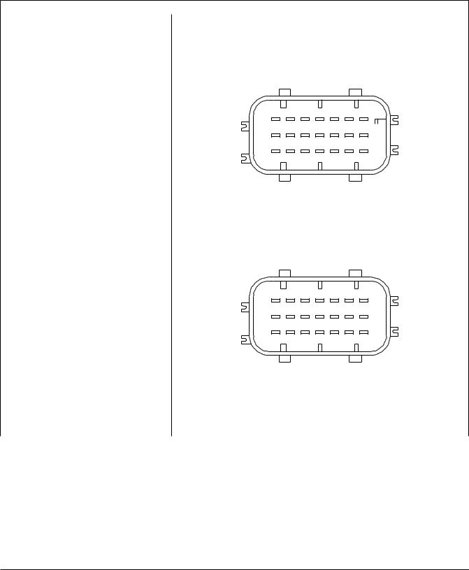
Remove the X3 (electric motor 2-pin) |
|
|
|
|
connector from the transmission control unit |
|
|
|
|
(TCU). Check the electric motor power |
|
|
|
|
circuit. |
|
|
|
|
|
2 |
|
|
1 |
|
06/01/2004 |
X3 |
f544485 |
|
|
|
|
|
|
Check for voltage between pin 1 (power |
Voltage drops more than 0.2 volts |
|
Repair or replace the wiring as |
|
circuit 232) of the X3 connector and the |
from the voltage measured at the |
|
needed. See Section 54.06, Subject |
|
battery ground terminal. |
battery. |
|
100. |
|
|
|
|
|
|
|
Voltage is within 0.2 volts of the |
|
Go to the next row in the table. |
|
|
voltage measured at the battery. |
|
|
|
Business Class M2 Workshop Manual, Supplement 20, September 2011 |
301/1 |
Freightliner AMT3 |
and Mercedes-Benz Automated-Manual |
26.03 |
Transmissions |
Troubleshooting Without Fault Codes
Electrical Pre-Test
Procedure |
Result |
|
|
|
|
Action |
|||||||||||
|
|
|
|
|
|
|
|
|
|
|
|
|
|
|
|
|
|
Check for resistance between pin 2 |
Resistance is greater than 0.3 ohms. |
|
Repair or replace the wiring as |
||||||||||||||
(ground) of the X3 connector and the |
|
|
|
|
|
|
|
|
|
|
|
|
|
needed. See Section 54.06, Subject |
|||
battery ground terminal. |
|
|
|
|
|
|
|
|
|
|
|
|
100. |
|
|
||
|
|
|
|
|
|
|
|
|
|
|
|
|
|
|
|
|
|
|
Resistance is 0.3 ohms or less. |
|
Go to the next row in the table. |
||||||||||||||
|
|
|
|
|
|
|
|
|
|
|
|
|
|
|
|
|
|
Remove the X1 (vehicle 21-pin) connector |
|
|
|
|
|
|
|
|
|
|
|
|
|
|
|
|
|
from the transmission control unit (TCU). |
|
|
|
|
|
|
|
|
|
|
|
|
|
|
|
|
|
Check the battery power circuit. |
|
|
|
|
|
|
|
|
|
|
|
|
|
|
|
|
|
|
|
|
|
|
|
|
|
|
|
|
|
|
|
|
|
|
|
|
21 |
18 |
15 |
12 |
9 |
6 |
3 |
|
|
|
|||||||||
|
|
|
20 |
17 |
14 |
11 |
8 |
5 |
2 |
|
|
|
|||||||
|
|
|
|
|
|
19 |
16 |
13 |
10 |
7 |
4 |
1 |
|
|
|
||||
|
|
|
|
|
|
|
|
|
|
|
|
|
|
|
|
|
|
|
|
|
07/16/2004 |
|
|
|
|
|
|
|
|
X1 |
|
|
|
|
|
|
f544483b |
||
|
|
|
|
|
|
|
|
|
|
|
|
|
|
|
|
||||
Check for voltage from pins 12 and 15 |
Voltage drops more than 0.2 volts |
|
|
Repair or replace the wiring as |
|||||||||||||||
(battery power circuit 232D) of the X1 |
from the voltage measured at the |
|
|
|
needed. See Section 54.06, Subject |
||||||||||||||
connector to the battery ground terminal. |
battery. |
|
|
|
|
|
100. |
|
|
|
|
|
|
||||||
|
|
|
|
|
|
|
|
|
|
|
|
|
|
|
|
|
|||
|
Voltage is within 0.2 volts of the |
|
|
|
Go to the next row in the table. |
||||||||||||||
|
voltage measured at the battery. |
|
|
|
|
|
|
|
|
|
|
|
|||||||
|
|
|
|
|
|
|
|
|
|
|
|
|
|
|
|
|
|
|
|
Turn on the ignition switch. Check the |
|
|
|
|
|
|
|
|
|
|
|
|
|
|
|
|
|
|
|
ignition power circuit. |
|
|
|
|
|
|
|
|
|
|
|
|
|
|
|
|
|
|
|
|
|
|
|
|
|
|
|
|
|
|
|
|
|
|
|||||
|
|
|
|
|
|
|
|
|
15 |
12 |
|
6 |
3 |
|
|
|
|||
|
21 |
18 |
9 |
|
|
|
|||||||||||||
|
|
|
|
||||||||||||||||
|
|
|
20 |
17 |
14 |
11 |
8 |
5 |
2 |
|
|
|
|||||||
|
|
|
|
19 |
16 |
13 |
10 |
7 |
4 |
1 |
|
|
|
||||||
|
|
|
|
|
|
|
|
|
|
|
|
|
|
|
|
|
|
|
|
|
07/16/2004 |
|
|
|
|
|
|
|
|
X1 |
|
|
|
|
|
|
f544483c |
||
|
|
|
|
|
|
|
|
|
|
|
|
|
|
|
|
||||
Check for voltage from pin 9 (ignition power |
Voltage drops more than 0.2 volts |
|
|
Repair or replace the wiring as |
|||||||||||||||
circuit 232E) of the X1 connector to the |
from the voltage measured at the |
|
|
|
needed. See Section 54.06, Subject |
||||||||||||||
battery ground terminal. |
battery. |
|
|
|
|
|
100. |
|
|
|
|
|
|
||||||
|
|
|
|
|
|
|
|
|
|
|
|
|
|
|
|
|
|||
|
Voltage is within 0.2 volts of the |
|
|
|
Go to the next row in the table. |
||||||||||||||
|
voltage measured at the battery. |
|
|
|
|
|
|
|
|
|
|
|
|||||||
301/2 |
Business Class M2 Workshop Manual, Supplement 20, September 2011 |

Freightliner AMT3 and Mercedes-Benz Automated-Manual |
26.03 |
Transmissions |
Troubleshooting Without Fault Codes
Electrical Pre-Test
Procedure |
Result |
|
|
|
Action |
||||||||||
|
|
|
|
|
|
|
|
|
|
|
|
|
|
|
|
Turn off the ignition switch. Check the |
|
|
|
|
|
|
|
|
|
|
|
|
|
|
|
ignition ground circuit. |
|
|
|
|
|
|
|
|
|
|
|
|
|
|
|
|
|
|
|
|
|
|
|
|
|
|
|
|
|
|
|
|
|
|
|
|
|
|
|
|
|
|
|
|
|
|
|
|
21 |
18 |
15 |
12 |
9 |
6 |
3 |
|
|
20 |
17 |
14 |
11 |
8 |
5 |
2 |
|
|
19 |
16 |
13 |
10 |
7 |
4 |
1 |
|
|
07/21/2004 |
|
|
X1 |
|
|
f544483d |
|
With the ignition switch off, check for |
Resistance is greater than 0.3 ohms. |
Repair or replace the wiring as |
||||||
resistance between pins 18 and 21 |
|
|
|
needed. See Section 54.06, Subject |
||||
(ground) of the X1 connector and the |
|
|
|
100. |
|
|
||
battery ground terminal. |
Resistance is 0.3 ohms or less. |
|
Go to the next row in the table. |
|||||
|
|
|||||||
Turn off the ignition switch. Check the |
|
|
|
|
|
|
|
|
J1587 wiring. |
|
|
|
|
|
|
|
|
|
21 |
18 |
15 |
12 |
9 |
6 |
3 |
|
|
20 |
17 |
14 |
11 |
8 |
5 |
2 |
|
|
19 |
16 |
13 |
10 |
7 |
4 |
1 |
|
|
07/21/2004 |
|
|
X1 |
|
|
f544483e |
|
Check for DC voltage from pins 11 and 14 |
Voltage is less than 1 or more than 4 |
Troubleshoot the J1587 datalink. |
||||||
(J1587 datalink) of the X1 connector to the |
volt(s) for DC (less than 1 or more |
|
|
|
|
|||
battery ground terminal. |
than 3 for AC). |
|
|
|
|
|
|
|
NOTE: If the meter cannot display the |
Voltage is between 1 and 4 volts for |
Go to the next row in the table. |
||||||
rapidly shifting DC voltage, measure AC |
||||||||
DC (1±3 volts AC). |
|
|
|
|
|
|
||
voltage instead. |
|
|
|
|
|
|
||
|
|
|
|
|
|
|
||
Turn off the ignition switch. Check the |
|
|
|
|
|
|
|
|
J1939 wiring. |
|
|
|
|
|
|
|
|
|
21 |
18 |
15 |
12 |
9 |
6 |
3 |
|
|
20 |
17 |
14 |
11 |
8 |
5 |
2 |
|
|
19 |
16 |
13 |
10 |
7 |
4 |
1 |
|
|
07/16/2004 |
|
|
X1 |
|
|
f544483a |
|
Business Class M2 Workshop Manual, Supplement 20, September 2011 |
301/3 |

Freightliner AMT3 |
and Mercedes-Benz Automated-Manual |
26.03 |
Transmissions |
Troubleshooting Without Fault Codes
Electrical Pre-Test
Procedure |
Result |
Action |
|
|
|
|
|
With the ignition switch off, remove the X1 |
Resistance is less than 55 or greater |
Troubleshoot the J1939 datalink. See |
|
connector from the TCU and check for |
than 65 ohms. |
Freightliner Service Bulletin 54-133. |
|
resistance between pins 7 and 13 (J1939 |
|
|
|
Resistance is between 55 and 65 |
The vehicle has passed the electrical |
||
datalink). |
|||
ohms. |
pre-test. Troubleshoot active fault |
||
|
|||
|
|
codes, if any. |
|
|
Table 1, Electrical Pre-Test |
|
NOTE: To see the identi®cation plate on the TCU it may be necessary to remove the splash guard.
|
|
|
|
0 0 3 |
2 0 0 4 |
|
|
4 7 7 |
0 0 1 |
0 0 6 |
0 |
|
|
|
|
A |
9 7 0 |
2 6 0 |
0 3 |
5 9 |
000525 |
||
|
|
|
|
3 |
|
|
4 |
5
1
2
10/05/2006 |
f261384 |
NOTE: The TCU and X-Y Actuator each have their own WABCO identi®cation plate (arrows) with unique serial numbers.
1. TCU (Transmission |
4. |
Serial Number |
Control Unit) |
5. |
X-Y Actuator |
2.Splash Guard
3.WABCO Identi®cation Plate
Fig. 1, Serial Numbers for TCU and X-Y Actuator
|
DaimlerChrysler |
|
1 |
|
|
|
|
|
Bez: G 60−6 |
|
2 |
|
IdNr 715053 123456 |
|
|
|
|
|
|
|
Code C07−00036−031 |
|
|
|
M−C |
|
|
|
Var. 041962 |
|
|
|
|
DaimlerChrysler |
|
|
|
Bez: G 60−6 |
|
|
|
IdNr 715053 123456 |
|
|
|
Code C07−00036−031 |
|
|
|
M−C |
|
|
|
Var. 041962 |
|
10/05/2006 |
|
f261383 |
|
1. |
Transmission |
2. |
Serial Number |
|
Identi®cation Plate |
|
|
Fig. 2, Transmission Serial Number
Troubleshooting Tables, No
Fault Codes
In a few cases there will be a de®nite problem and no J1587 fault code will be sent.
•If the engine will not crank and there are no transmission fault codes, see Table 2.
301/4 |
Business Class M2 Workshop Manual, Supplement 20, September 2011 |

Freightliner AMT3 and Mercedes-Benz Automated-Manual |
26.03 |
Transmissions |
Transmission Range Faults (PID 162 and 163)
Transmission Range Faults
Transmission Range-Selected
Faults (PID 162)
There is one transmission range-selected fault covered in these procedures.
•For PID 162, FMI 02, see Table 1 for procedures.
Transmission Range-Attained
Faults (PID 163)
There is one transmission range-attained fault covered in these procedures.
•For PID 163, FMI 02, see Table 2 for procedures.
PID 162, FMI 02ÐThe Transmission Is Not Properly Calibrated
Failure Reason:
•The gears are caught in an intermediate position.
•The transmission software does not allow shifting.
Problem |
Procedure |
Result |
Action |
|
|
|
|
There are other |
Check for other MID 130 fault codes. |
Other fault codes |
Troubleshoot the |
active transmission |
|
are active. |
other active fault |
faults. |
|
|
codes. |
|
|
|
|
|
|
No other fault |
Go to the next step |
|
|
codes are active. |
in the table. |
|
|
|
|
The transmission |
Complete a learning procedure using either ServiceLink or |
The fault is no |
No further action is |
needs to be |
the SmartShift control. |
longer active. |
needed. |
recalibrated. |
To complete a learning procedure using the SmartShift |
|
|
|
|
|
|
|
control: |
|
|
|
1. Ensure that the parking brake is set. |
|
|
|
2. With the ignition turned off, pull and hold the SmartShift |
|
|
|
control toward steering wheel. |
|
|
|
NOTE: The SmartShift control must be kept in this position |
|
|
|
until the gear display clears at the end of the procedure. |
|
|
|
3. Turn on the ignition. The normal warm up procedure will |
|
|
|
initiate and an 'X' will display on the current gear indicator. |
|
|
|
The fault is still |
Contact |
|
|
Your transmission may be heard shifting. |
||
|
active. |
Freightliner |
|
|
4. Wait until the current gear indicator displays an 'N' |
||
|
|
Technical Service |
|
|
(about 30 seconds) and an audible alert sounds. Start the |
|
Support. |
|
engine within 10 seconds of the audible alert. |
|
|
|
5. The engine will raise a few rpm, then fall back to idle, |
|
|
|
and an audible alert will sound. Turn off the engine within |
|
|
|
10 seconds of audible alert. When the gear display clears, |
|
|
|
this procedure is complete. |
|
|
|
NOTE: If during this procedure an 'SM' or 'X' (after the |
|
|
|
warm up procedure) appears in the gear display, stop, turn |
|
|
|
off the ignition, and wait for the gear display to go dark. |
|
|
|
Then start over. This may need to be repeated several |
|
|
|
times. |
|
|
Table 1, The Transmission Is Not Properly Calibrated
Business Class M2 Workshop Manual, Supplement 20, September 2011 |
316/1 |

Freightliner AMT3 |
and Mercedes-Benz Automated-Manual |
26.03 |
Transmissions |
Transmission Range Faults (PID 162 and 163)
PID 163, FMI 02ÐThe Gears Do Not Shift Properly
Failure Reason:
• There is a defect in the TCU.
• There is a defect in the speed sensor.
• There is a defect in the actuator.
• The transmission software is not properly programmed.
• The datalink does not recognize the transmission type.
Problem |
Procedure |
Result |
Action |
|
|
|
|
There are other |
Check for other MID 130 fault codes. |
Other fault codes are |
Troubleshoot the other |
active transmission |
|
active. |
active fault codes. |
faults. |
|
|
|
|
No other fault codes are |
Go to the next step in the |
|
|
|
||
|
|
active. |
table. |
|
|
|
|
There is a |
Using the ServiceLink diagnostics template, |
The x-y actuator |
No further action is needed. |
transmission |
view the different gear positions, check that |
responds properly and |
|
software problem. |
the clutch opens and closes, and that the |
the fault clears. |
|
|
x-y actuator moves from reverse, 1st, and |
|
|
|
The fault is still active. |
Go to the next step in the |
|
|
2nd gears. |
||
|
|
table. |
|
|
|
|
|
|
|
|
|
There is component |
Do a visual inspection of the x-y actuator, |
Damaged components |
Contact Mercedes-Benz |
damage in the |
the hydraulic system, and the transmission |
are found. |
Transmissions Service |
transmission. |
shift system. |
|
Support with the AGS |
|
|
|
codes and results of the |
|
|
|
electrical pre-test. |
|
|
|
NOTE: One hour of |
|
|
|
troubleshooting time is |
|
|
|
alloted for printing the AGS |
|
|
|
codes and completing the |
|
|
|
electrical pre-test. |
|
|
|
1. Using ServiceLink, print |
|
|
|
the AGS codes (130). |
|
|
No damaged |
2. Complete the electrical |
|
|
components are found. |
|
|
|
pre-test result sheet in |
|
|
|
|
|
|
|
|
Subject 301. |
|
|
|
3. With the results, contact |
|
|
|
Mercedes-Benz |
|
|
|
Transmissions Service |
|
|
|
Support by fax |
|
|
|
(503.961.8435), email |
|
|
|
(MBTServiceSupport@ |
|
|
|
Freightliner.com), or phone |
|
|
|
(503.745.4965 or |
|
|
|
503.745.4988). |
|
Table 2, The Gears Do Not Shift Properly |
|
|
316/2 |
Business Class M2 Workshop Manual, Supplement 20, September 2011 |

Freightliner AMT3 and Mercedes-Benz Automated-Manual |
26.03 |
Transmissions |
Output Shaft Speed Sensor Faults (PID 191)
Output Shaft Speed Sensor
Faults (PID 191)
There are four output shaft speed sensor faults covered in these procedures. One troubleshooting procedure is used to correct FMI 02, 05, and 08. A separate procedure is used for FMI 14.
•For PID 191, FMI 02, 05, and 08 see Table 1 for procedures and pin identi®cation.
•For PID 191, FMI 14, see Table 2 for procedures.
PID 191, FMI 02, 05, 08ÐThe Output Shaft Speed Sensor Circuit Gives Invalid Data, Is Open, or Not Broadcasting a Signal
Failure Reason: |
|
|
|
|
|
|
|
|
|
|
|
|
|
|
|
|
|
|
|
|
|
|
|
|
|
|
• The TCU has a hardware prob- |
|
|
|
|
|
|
|
|
|
|
|
|
|
|
|
|
|
|
|
|
|
|
|
|
|
|
lem. |
|
|
|
|
|
|
|
|
|
|
|
|
|
|
|
|
|
|
|
|
|
|
|
|
|
|
• The sensor is mounted too loose |
|
|
|
|
|
|
|
|
|
|
|
|
|
|
|
|
|
|
|
|
|
|
|
|
|
|
(air gap too big). |
|
|
|
1 |
|
|
4 |
7 |
|
|
10 |
13 |
|
|
|
|
|
|
||||||||
• The sensor connectors are dam- |
|
|
|
|
|
|
|
|
|
|
|
|
|
|
|
|||||||||||
|
|
|
|
|
|
|
|
|
|
|
|
|
|
|
|
|
||||||||||
2 |
|
|
5 |
8 |
|
|
11 14 |
|
|
|
|
|
|
|||||||||||||
aged or bent. |
|
|
|
|
|
|
|
|
|
|
|
|
|
|
|
|
|
|
|
|
|
|
|
|
|
|
• The wiring harness has had an |
3 |
|
|
6 |
9 |
|
|
12 |
15 |
|
|
|
|
|
|
|||||||||||
|
|
|
|
|
|
|
|
|
|
|
|
|
|
|
|
|
|
|
|
|
|
|
|
|
||
|
|
|
|
|
|
|
|
|
|
|
|
|
|
|
|
|
|
|
|
|
|
|
|
|
||
electrical failure. |
|
|
|
|
|
|
|
|
|
|
|
|
|
|
|
|
|
|
|
|
|
|
|
|
|
|
|
|
|
|
|
|
|
|
|
|
|
|
|
|
|
|
|
|
|
|
|
|
|
|
|
||
|
|
|
|
|
|
|
|
|
|
X2 |
|
|
|
|
|
|
|
|
|
|
|
|||||
• Either one of the sensors or the |
07/16/2004 |
|
|
|
|
|
|
|
|
|
|
|
|
|
|
|
|
|
|
|
f544484k |
|||||
TCU has failed. |
|
|
|
|
|
|
|
|
|
|
|
|
|
|
|
|
|
|
|
|
|
|
|
|
|
|
|
|
|
|
|
|
|
|
|
|
|
|
|
|
|
|
|
|
|
|
|
|
|
|
|
|
|
Procedure |
Results |
|
|
|
|
|
|
|
|
|
|
|
|
|
|
|
Action |
|||||||||
|
|
|
|
|
|
|
|
|
|
|
|
|
|
|
|
|
|
|
|
|
|
|
|
|||
Turn on the ignition switch and wait for |
Fault code SID 254, FMI 12 is active. |
|
Go to Subject 309 and troubleshoot |
|||||||||||||||||||||||
the current gear display to power up. |
|
|
|
|
|
|
|
|
|
SID 254, FMI 12. |
||||||||||||||||
|
|
|
|
|
|
|
|
|
|
|
|
|
|
|
|
|
|
|
|
|
|
|
|
|||
|
SID 254, FMI 12 is not active. |
|
Go to the next row in the table. |
|||||||||||||||||||||||
|
|
|
|
|
|
|
|
|
|
|
|
|
|
|
|
|
|
|
|
|
|
|
|
|||
Remove both output shaft speed |
The fault clears after a test drive. |
|
No further action needed. |
|||||||||||||||||||||||
sensors. Reinstall and tighten the sensor |
|
|
|
|
|
|
|
|
|
|
|
|
|
|
|
|
|
|
|
|
|
|
|
|
|
|
The fault remains active. |
|
Go to the next row in the table. |
||||||||||||||||||||||||
28 lbf´ft (38 N´m). |
|
|||||||||||||||||||||||||
|
|
|
|
|
|
|
|
|
|
|
|
|
|
|
|
|
|
|
|
|
|
|
|
|||
Turn off the ignition switch and wait for |
The connector pins are damaged or |
|
Repair or replace the damage. |
|||||||||||||||||||||||
the current gear display to power down. |
bent. |
|
|
|
|
|
|
|
|
|
|
|
|
|
|
|
|
|
||||||||
Remove both sensor connectors and |
|
|
|
|
|
|
|
|
|
|
|
|
|
|
|
|
|
|
|
|
|
|
|
|
|
|
There is no damage to either |
|
Go to the next row in the table. |
||||||||||||||||||||||||
visually inspect the pins. |
|
|||||||||||||||||||||||||
connector. |
|
|
|
|
|
|
|
|
|
|
|
|
|
|
|
|
|
|||||||||
|
|
|
|
|
|
|
|
|
|
|
|
|
|
|
|
|
|
|||||||||
|
|
|
|
|
|
|
|
|
|
|
|
|
|
|
|
|
|
|
|
|
|
|
|
|||
Check the upper sensor for continuity: |
There is an open circuit. |
|
Replace the transmission wiring |
|||||||||||||||||||||||
(1) X2 connector pin 1 to sensor pin 2; |
|
|
|
|
|
|
|
|
|
harness (see Subject 180). |
||||||||||||||||
(2) X2 connector pin 15 to sensor pin 1; |
|
|
|
|
|
|
|
|
|
|
|
|
|
|
|
|
|
|
|
|
|
|
|
|
|
|
The wiring is OK. |
|
Go to the next row in the table. |
||||||||||||||||||||||||
(3) X2 connector pin 14 to sensor pin 4. |
|
|||||||||||||||||||||||||
|
|
|
|
|
|
|
|
|
|
|
|
|
|
|
|
|
|
|
|
|
|
|
|
|||
Check the lower sensor for continuity: |
There is an open circuit. |
|
Replace the transmission wiring |
|||||||||||||||||||||||
(1) X2 connector pin 1 to sensor pin 2; |
|
|
|
|
|
|
|
|
|
harness (see Subject 180). |
||||||||||||||||
(2) X2 connector pin 15 to sensor pin 1; |
|
|
|
|
|
|
|
|
|
|
|
|
|
|
|
|
|
|
|
|
|
|
|
|
|
|
The wiring is OK. |
|
Go to the next row in the table. |
||||||||||||||||||||||||
(3) X2 connector pin 9 to sensor pin 3. |
|
|||||||||||||||||||||||||
|
|
|
|
|
|
|
|
|
|
|
|
|
|
|
|
|
|
|
|
|
|
|
|
|||
Check all four pins of each sensor |
Voltage or continuity is found. |
|
Replace the transmission wiring |
|||||||||||||||||||||||
connector for voltage and for continuity |
|
|
|
|
|
|
|
|
|
harness (see Subject 180). |
||||||||||||||||
to ground. |
|
|
|
|
|
|
|
|
|
|
|
|
|
|
|
|
|
|
|
|
|
|
|
|
|
|
There is zero voltage and no continuity. |
Go to the next row in the table. |
|||||||||||||||||||||||||
|
||||||||||||||||||||||||||
Business Class M2 Workshop Manual, Supplement 20, September 2011 |
317/1 |
Freightliner AMT3 |
and Mercedes-Benz Automated-Manual |
26.03 |
Transmissions |
Output Shaft Speed Sensor Faults (PID 191)
PID 191, FMI 02, 05, 08ÐThe Output Shaft Speed Sensor Circuit Gives Invalid Data, Is Open, or Not Broadcasting a Signal
Failure Reason:
•The TCU has a hardware problem.
•The sensor is mounted too loose
(air gap too big). |
|
|
|
|
1 |
|
4 |
7 |
|
|
10 |
13 |
|
|
|
|
|
|
|||||||
|
|
|
|
|
|
|
|
|
|
|
|||||||||||||||
• The sensor connectors are dam- |
|
|
|
|
|
|
|
|
|
|
|
|
|
|
|||||||||||
|
|
|
|
|
|
|
|
|
|
|
|
|
|
|
|
||||||||||
2 |
5 |
8 |
|
|
11 14 |
|
|
|
|
|
|
||||||||||||||
aged or bent. |
|
|
|
|
|
|
|
|
|
|
|
|
|
|
|
|
|
|
|
|
|
|
|
|
|
• The wiring harness has had an |
3 |
6 |
9 |
|
|
12 |
15 |
|
|
|
|
|
|
||||||||||||
|
|
|
|
|
|
|
|
|
|
|
|
|
|
|
|
|
|
|
|
|
|
|
|
|
|
|
|
|
|
|
|
|
|
|
|
|
|
|
|
|
|
|
|
|
|
|
|
|
|
|
|
electrical failure. |
|
|
|
|
|
|
|
|
|
|
|
|
|
|
|
|
|
|
|
|
|
|
|
|
|
|
|
|
|
|
|
|
|
|
|
|
|
|
|
|
|
|
|
|
|
|
|
|
|
|
|
|
|
|
|
|
|
|
|
|
|
X2 |
|
|
|
|
|
|
|
|
|
|
|
||||
• Either one of the sensors or the |
07/16/2004 |
|
|
|
|
|
|
|
|
|
|
|
|
|
|
|
|
|
|
|
f544484k |
||||
TCU has failed. |
|
|
|
|
|
|
|
|
|
|
|
|
|
|
|
|
|
|
|
|
|
|
|
|
|
|
|
|
|
|
|
|
|
|
|
|
|
|
|
|
|
|
|
|
|
|
|
|
|
|
|
Procedure |
Results |
|
|
|
|
|
|
|
|
|
|
|
|
|
|
|
|
|
Action |
||||||
|
|
|
|
|
|
|
|
|
|
|
|
|
|
|
|
|
|
|
|
|
|
|
|
||
Using a sensor known to be good, |
The fault becomes inactive. |
|
|
|
No further action needed. |
||||||||||||||||||||
replace each sensor in turn (see |
|
|
|
|
|
|
|
|
|
|
|
|
|
|
|
|
|
|
|
|
|
|
|
|
|
The fault is still active. |
|
|
|
Contact Mercedes-Benz Transmissions |
|||||||||||||||||||||
Subject 120 for procedures). |
|
|
|
||||||||||||||||||||||
|
|
|
|
|
|
|
|
|
Service Support with the AGS codes |
||||||||||||||||
|
|
|
|
|
|
|
|
|
|
||||||||||||||||
|
|
|
|
|
|
|
|
|
|
and results of the electrical pre-test. |
|||||||||||||||
|
|
|
|
|
|
|
|
|
|
NOTE: One hour of troubleshooting |
|||||||||||||||
|
|
|
|
|
|
|
|
|
|
time is alloted for printing the AGS |
|||||||||||||||
|
|
|
|
|
|
|
|
|
|
codes and completing the electrical |
|||||||||||||||
|
|
|
|
|
|
|
|
|
|
pre-test. |
|
|
|
|
|
|
|
|
|
|
|||||
|
|
|
|
|
|
|
|
|
|
1. Using ServiceLink, print the AGS |
|||||||||||||||
|
|
|
|
|
|
|
|
|
|
codes (130). |
|||||||||||||||
|
|
|
|
|
|
|
|
|
|
2. Complete the electrical pre-test |
|||||||||||||||
|
|
|
|
|
|
|
|
|
|
result sheet in Subject 301. |
|||||||||||||||
|
|
|
|
|
|
|
|
|
|
3. With the results, contact Mercedes- |
|||||||||||||||
|
|
|
|
|
|
|
|
|
|
Benz Transmissions Service Support |
|||||||||||||||
|
|
|
|
|
|
|
|
|
|
by fax (503.961.8435), email |
|||||||||||||||
|
|
|
|
|
|
|
|
|
|
(MBTServiceSupport@ |
|||||||||||||||
|
|
|
|
|
|
|
|
|
|
Freightliner.com), or phone |
|||||||||||||||
|
|
|
|
|
|
|
|
|
|
(503.745.4965 or 503.745.4988). |
|||||||||||||||
Table 1, The Output Shaft Speed Sensor Circuit Gives Invalid Data, Is Open, or Not Broadcasting a Signal
PID 191, FMI 14ÐThe Output Shaft Speed Sensor Is Providing Invalid Data
Failure Reason
•The antilock brake system (ABS) is not broadcasting wheel speed data.
•There is a defective output shaft speed sensor.
Procedure |
Result |
Action |
|
|
|
Check for other PID 191 fault codes. |
Other PID 191 fault codes |
Troubleshoot PID 191. See |
|
are active. |
Table 1. |
|
|
|
|
No other PID 191 fault |
Go to the next step in the |
|
codes are active. |
table. |
317/2 |
Business Class M2 Workshop Manual, Supplement 20, September 2011 |

Freightliner AMT3 and Mercedes-Benz Automated-Manual |
26.03 |
Transmissions |
Output Shaft Speed Sensor Faults (PID 191)
PID 191, FMI 14ÐThe Output Shaft Speed Sensor Is Providing Invalid Data
Failure Reason
•The antilock brake system (ABS) is not broadcasting wheel speed data.
•There is a defective output shaft speed sensor.
Procedure |
Result |
Action |
|
|
|
Check for active fault codes in MID 136 (ABS). |
Active MID 136 fault codes |
Troubleshoot the ABS system |
|
are found. |
(see the applicable section in |
|
|
Group 42). |
Table 2, The Output Shaft Speed Sensor Is Providing Invalid Data
Business Class M2 Workshop Manual, Supplement 20, September 2011 |
317/3 |

Freightliner AMT3 and Mercedes-Benz Automated-Manual |
26.03 |
Transmissions |
|
|
Speci®cations |
For a schematic of the AGS transmission wiring behind the X2 (transmission) connector, see Fig. 1. For a schematic of the AGS transmission wiring behind the X1 (main vehicle) and X3 (electric motor) connectors, see drawing G06-49466.
For a list of special tools, see Table 1.
Input Shaft Speed |
|
Output Shaft Speed Sensor |
|
Output Shaft Speed Sensor |
|||
|
Sensor |
|
|
(9:00 position) |
|
(11:00 position) |
|
|
|
|
3 |
2 |
|
S |
2 |
|
|
|
S |
GND |
|
GND |
|
|
|
|
|
+12V |
|
+12V |
|
2 |
1 |
|
|
1 |
|
1 |
|
13 |
11 |
|
9 |
|
14 |
15 |
1 |
|
|
|
X2 Connector |
|
|
|
|
7 |
3 |
2 |
6 |
10 |
5 |
4 |
12 |
2 |
1 |
2 |
1 |
2 |
1 |
2 |
1 |
Gear Position Sensor |
Rail Position Sensor |
Clutch Position Sensor |
Fluid Level Sensor |
||||
|
(Front) |
|
(Rear) |
|
|
(Pentosin) |
|
02/01/2005 |
|
|
|
|
|
Circuit is closed when full |
|
|
|
|
|
|
|
f544529 |
|
Fig. 1, AGS Transmission Wiring, X2 Connector
Special Tools for AGS Transmission
Tool |
Description |
Manufacturer |
Part Number |
Accumulator Torque Adaptor |
Kent-Moore |
J-47291 |
f580381
Low-Pressure Hose Disconnect Tool |
Kent-Moore |
J-47202 |
f580379a
Business Class M2 Workshop Manual, Supplement 20, September 2011 |
400/1 |

Freightliner AMT3 |
and Mercedes-Benz Automated-Manual |
|
26.03 |
Transmissions |
|
Speci®cations |
|
|
Special Tools for AGS Transmission
Tool |
Description |
Manufacturer |
Part Number |
High-Pressure Line Disconnect Tool |
Kent-Moore |
J-47201 |
f580379
Shift Finger Alignment Fork |
Kent-Moore |
J-47204 |
f580380
Shift Mechanism End Guide |
Kent-Moore |
J-47203 |
f580382
Table 1, Special Tools for AGS Transmission
For transmission installation torque values, see
Table 2.
Transmission Installation Torque Values
Description |
Size |
Class |
Torque: lbf´ft (N´m) |
||
|
|
|
|
||
Midship Bearing Bracket Capscrews |
3/4±11 |
Ð |
91 (123) |
||
|
|
|
|
||
Power Takeoff Unit (PTO) Mounting Capscrews |
M10 |
10.9 |
43 (58) |
||
|
|
|
|
|
|
Transmission Fluid Drain Plug |
M24 |
Ð |
42 |
(57) |
|
|
|
|
|
|
|
Transmission Fluid Fill Plug |
M24 |
Ð |
42 |
(57) |
|
|
|
|
|
||
Transmission Mounting Bolts |
M10 x 1.5 |
8.8 |
33 (45) |
||
|
|
|
|
||
U-Joint End Cap Bolts |
3/8±24 |
Ð |
50 (68) |
||
|
|
|
|
||
1/2±20 |
Ð |
110 |
(149) |
||
|
|||||
Table 2, Transmission Installation Torque Values
For AGS assembly torque values, see Table 3.
AGS Assembly Torque Values
Description |
Size |
Torque: lbf´ft (N´m) |
Torque: lbf´in (N´cm) |
|
|
|
|
Accumulator Hydraulic Fitting |
M30 |
59 (80) |
Ð |
|
|
|
|
X-Y Actuator Mounting Capscrews |
M8 |
17 (23) |
Ð |
400/2 |
Business Class M2 Workshop Manual, Supplement 20, September 2011 |

Freightliner AMT3 and Mercedes-Benz Automated-Manual |
26.03 |
Transmissions |
|
|
Speci®cations |
AGS Assembly Torque Values
Description |
Size |
Torque: lbf´ft (N´m) |
Torque: lbf´in (N´cm) |
|
|
|
|
AGS Central Unit Mounting Capscrews |
M8 |
17 (23) |
Ð |
|
|
|
|
Clutch Actuator Hydraulic Fittings |
M30 |
37 (50) |
Ð |
|
|
|
|
Clutch Actuator Mounting Capscrews |
M8 |
17 (23) |
Ð |
|
|
|
|
Pressure-Limiting Valve Adjusting Screw |
M6 |
Ð |
63±71 (700±800) |
|
|
|
|
Reservoir Base Fasteners |
M8 |
11 (15) |
Ð |
|
|
|
|
Reservoir Top Fasteners |
M6 |
Ð |
71 (800) |
|
|
|
|
Rotational Speed (RPM) Sensors |
Ð |
28 (38) |
Ð |
|
|
|
|
Shift Rod Setscrew |
M12 |
22 (30) |
Ð |
|
|
|
|
Transmission Control Unit (TCU) Mounting Screws |
M8 |
Ð |
44±53 (500±600) |
|
|
|
|
TCU Splash Guard Mounting Capscrews |
M8 |
17 (23) |
Ð |
Table 3, AGS Assembly Torque Values |
|
||
For AGS transmission gear ratios, see Table 4.
AGS Transmission Gear Ratios
Model |
Gear |
Ratio |
|
|
|
|
1 |
9.201 |
|
|
|
|
2 |
5.230 |
|
|
|
|
3 |
3.145 |
MBT520-6DA |
|
|
4 |
2.034 |
|
|
|
|
|
5 |
1.374 |
|
|
|
|
6 |
1.000 |
|
|
|
|
R |
8.649 |
|
|
|
|
1 |
6.700 |
|
|
|
|
2 |
3.810 |
|
|
|
|
3 |
2.290 |
MBT660-6OA |
|
|
4 |
1.480 |
|
|
|
|
|
5 |
1.000 |
|
|
|
|
6 |
0.730 |
|
|
|
|
R |
6.290 |
Table 4, AGS Transmission Gear Ratios
For a list of proprietary fault codes viewable on ServiceLink, see Table 5.
|
AGS Proprietary Fault Codes (J1708) |
|
|
Fault Code |
Description |
|
|
3000109 |
High voltage supply voltageÐexternal (connector X1/12 and X1/15) |
Business Class M2 Workshop Manual, Supplement 20, September 2011 |
400/3 |

Freightliner AMT3 |
and Mercedes-Benz Automated-Manual |
|
26.03 |
Transmissions |
|
Speci®cations |
|
|
|
AGS Proprietary Fault Codes (J1708) |
|
|
Fault Code |
Description |
|
|
3000113 |
High voltage ignition key lineÐexternal (connector X1/9) |
|
|
3000209 |
Low voltage supply voltageÐexternal (connector X1/12 and X1/15) |
|
|
3000213 |
Low voltage ignition key lineÐexternal (connector X1/9) |
|
|
3001210 |
EEPROM parameter values errorÐinternal |
|
|
3001510 |
Clutch displacement control module parameter errorÐinternal |
|
|
3001781 |
Clutch calibration offset off limitÐinternal |
|
|
3002009 |
Open load supply voltageÐexternal (connector X1/12 and X1/15) |
|
|
3002016 |
Open load/Short circuit VCC temperature sensor circuit boardÐinternal |
|
|
3002017 |
Open load/Short circuit VCC temperature sensor pumpÐinternal |
|
|
3002116 |
Short circuit GND temperature sensor circuit boardÐinternal |
|
|
3002117 |
Short circuit GND temperature sensor pumpÐinternal |
|
|
3002214 |
Short circuit VCC peripherals supplyÐexternal (connector X2/15) |
|
|
3003001 |
EBC1 message timeoutÐexternal (J1939) |
|
|
3003101 |
EEC1 message timeoutÐexternal (J1939) |
|
|
3003201 |
EEC2 message timeoutÐexternal (J1939) |
|
|
3003301 |
EEC3 message timeoutÐexternal (J1939) |
|
|
3003401 |
ERC1 message timeoutÐexternal (J1939) |
|
|
3003501 |
Wheel speed information message timeoutÐexternal (J1939) |
|
|
3003601 |
CruiseControl (VCU) message timeoutÐexternal (J1939) |
|
|
3003701 |
CruiseControl (bulkhead) message timeoutÐexternal (J1939) |
|
|
3003801 |
Engine con®guration message timeoutÐexternal (J1939) |
|
|
3003901 |
Retarder con®guration message timeoutÐexternal (J1939) |
|
|
3004001 |
Component identi®cation message timeoutÐexternal (J1939) |
|
|
3004101 |
PTO information message timeoutÐexternal (J1939) |
|
|
3006101 |
Incorrect engine dataÐexternal (J1939) |
|
|
3006201 |
Timeout converted engine data for clutch module (low priority)Ðinternal |
|
|
3006701 |
Incorrect retarder dataÐexternal (J1939) |
|
|
3006801 |
Incorrect ABS dataÐexternal (J1939) |
|
|
3006901 |
Incorrect internal dataÐinternal |
|
|
3007001 |
Incorrect clutch module dataÐinternal |
|
|
3007101 |
Incorrect automated gear shift module dataÐinternal |
|
|
3007201 |
Incorrect internal dataÐinternal |
|
|
3008881 |
Clutch overloadÐinternal |
|
|
3009280 |
Plausibility error actual transmission gear ratioÐinternal |
|
|
3009710 |
Test softwareÐinternal |
|
|
3009810 |
Test electronicÐinternal |
400/4 |
Business Class M2 Workshop Manual, Supplement 20, September 2011 |

Freightliner AMT3 and Mercedes-Benz Automated-Manual |
26.03 |
Transmissions |
|
|
Speci®cations |
|
AGS Proprietary Fault Codes (J1708) |
|
|
Fault Code |
Description |
|
|
3009910 |
Test bench mode activatedÐinternal |
|
|
3010390 |
Automatic module: signal group cruise control / retarderÐinternal |
|
|
3010690 |
Automatic module: signal output speedÐinternal |
|
|
3010790 |
Automatic module: signal group MRÐinternal |
|
|
3010890 |
Automatic module: signal group gear ratioÐinternal |
|
|
3010990 |
Automatic module: learning values engineÐinternal |
|
|
3011081 |
Plausibility error intended clutch position can not be reached within speci®ed timeÐinternal |
|
|
3011090 |
Automatic module: learning values transmissionÐinternal |
|
|
3011310 |
Clutch calibration data missing/errorÐinternal |
|
|
3011410 |
Clutch parameter errorÐinternal |
|
|
3011590 |
Automatic module: signal group shifting timeÐinternal |
|
|
3011690 |
Automatic module: signal group ABSÐinternal |
|
|
3011790 |
Automatic module: signal group pedal activationÐinternal |
|
|
3011890 |
Automatic module: signal group leverÐinternal |
|
|
3011990 |
Automatic module: error target systemÐinternal |
|
|
3012014 |
Open load peripherals supplyÐexternal (connector X2/15) |
|
|
3012019 |
Plausibility error valve relay V-V2 onÐinternal |
|
|
3012035 |
Open load power stage solenoid valve (clutch open 1)Ðinternal |
|
|
3012036 |
Open load power stage solenoid valve (clutch open 2)Ðinternal |
|
|
3012037 |
Open load power stage solenoid valve (clutch close 1)Ðinternal |
|
|
3012038 |
Open load power stage solenoid valve (clutch close 2)Ðinternal |
|
|
3012050 |
Open load speed sensor transmission output (DZ1)Ðexternal (connector X2/14) |
|
|
3012051 |
Open load speed sensor transmission inputÐexternal (connector X2/11) |
|
|
3012052 |
Open load speed sensor transmission output (D3)Ðexternal (connector X2/9) |
|
|
3012090 |
Automatic module: system identi®cation gearshift moduleÐinternal |
|
|
3012114 |
Short circuit to GND peripherals supplyÐexternal (connector X2/15) |
|
|
3012118 |
Plausibility error valve relay V-V1 offÐinternal |
|
|
3012119 |
Plausibility error valve relay V-V2 offÐinternal |
|
|
3012136 |
Short circuit GND power stage solenoid valve (clutch open 2)Ðinternal |
|
|
3012138 |
Short circuit GND power stage solenoid valve (clutch close 2)Ðinternal |
|
|
3012151 |
Short circuit GND speed sensor transmission inputÐexternal (connector X2/11 |
|
|
3012251 |
Short circuit VCC speed sensor transmission inputÐexternal (connector X2/11) |
|
|
3012461 |
Hydraulic level too low externalÐexternal |
|
|
3016201 |
Timeout converted engine data for clutch module (medium priority)Ðinternal |
|
|
3016401 |
Timeout driving direction informationÐinternal |
|
|
3016501 |
Timeout internal communication shift module to clutch module (medium priority)Ðinternal |
Business Class M2 Workshop Manual, Supplement 20, September 2011 |
400/5 |

Freightliner AMT3 |
and Mercedes-Benz Automated-Manual |
|
26.03 |
Transmissions |
|
Speci®cations |
|
|
|
AGS Proprietary Fault Codes (J1708) |
|
|
Fault Code |
Description |
|
|
3018681 |
Plausibility error clutch open request while inlet valves are closedÐinternal |
|
|
3018781 |
Plausibility error clutch open request while outlet valves are closedÐinternal |
|
|
3019480 |
Plausibility error driving directionÐinternal |
|
|
3019621 |
SmartShift lever data invalidÐexternal (connector X1/8, X1/11, X1/14) |
|
|
3019650 |
Tooth signal interruption speed sensor transmission output (DZ1)Ðexternal (connector X2/14) |
|
|
3019651 |
Tooth signal interruption speed sensor transmission inputÐexternal (connector X2/11) |
|
|
3019652 |
Tooth signal interruption speed sensor transmission output (D3)Ðexternal (connector X2/9) |
|
|
3020110 |
High voltage distance sensor supplyÐinternal |
|
|
3020111 |
Power supply high voltageÐexternal (connector X3/1) |
|
|
3020210 |
Low voltage distance sensor supplyÐinternal |
|
|
3020211 |
Power supply low voltageÐexternal (connector X3/1) |
|
|
3021010 |
Flash checksum errorÐinternal |
|
|
3021110 |
EEPROM calibration values errorÐinternal |
|
|
3021610 |
Clutch displacement offset failureÐinternal |
|
|
3022011 |
Supply voltage open loadÐexternal (connector X3/1) |
|
|
3022012 |
Open load GND connectionÐexternal (connector X1/18 and X1/21) |
|
|
3022015 |
Open load pressure sensor signalÐinternal |
|
|
3022018 |
Plausibility error valve relay V-V1 onÐinternal |
|
|
3022020 |
Open load GND pump motorÐexternal (connector X3/2) |
|
|
3022030 |
Open load power stage solenoid valve (selection direction R)Ðinternal |
|
|
3022031 |
Open load power stage solenoid valve (selection direction 5/6)Ðinternal |
|
|
3022032 |
Open load power stage solenoid valveÐinternal |
|
|
3022033 |
Open load power stage solenoid valve (gear direction 1,3,5)Ðinternal |
|
|
3022034 |
Open load power stage solenoid valve (pressure regulation)Ðinternal |
|
|
3022041 |
Open load distance sensor (gear)Ðinternal |
|
|
3022042 |
Open load distance sensor (selection)Ðinternal |
|
|
3022044 |
Open load distance sensor (clutch)Ðinternal |
|
|
3022060 |
Open loop power stage pump motorÐinternal |
|
|
3022115 |
Short circuit GND pressure sensor signalÐinternal |
|
|
3022130 |
Short circuit GND power stage solenoid valve (selection direction R)Ðinternal |
|
|
3022131 |
Short circuit GND power stage solenoid valve (selection direction 5/6)Ðinternal |
|
|
3022132 |
Short circuit GND power stage solenoid valve (gear direction R,2,4,6)Ðinternal |
|
|
3022133 |
Short circuit GND power stage solenoid valve (gear direction 1,3,5)Ðinternal |
|
|
3022134 |
Short circuit GND power stage solenoid valve (pressure regulation)Ðinternal |
|
|
3022135 |
Short circuit GND power stage solenoid valve (clutch open 1)Ðinternal |
|
|
3022137 |
Short circuit GND power stage solenoid valve (clutch close 1)Ðinternal |
400/6 |
Business Class M2 Workshop Manual, Supplement 20, September 2011 |

Freightliner AMT3 and Mercedes-Benz Automated-Manual |
26.03 |
Transmissions |
|
|
Speci®cations |
|
AGS Proprietary Fault Codes (J1708) |
|
|
Fault Code |
Description |
|
|
3022141 |
Short circuit GND distance sensor (gear)Ðinternal |
|
|
3022142 |
Short circuit GND distance sensor (selection)Ðinternal |
|
|
3022144 |
Short circuit GND distance sensor (clutch)Ðinternal |
|
|
3022160 |
Short circuit GND power stage pump motorÐinternal |
|
|
3022215 |
Short circuit VCC pressure sensor signalÐinternal |
|
|
3022241 |
Short circuit VCC distance sensor (gear)Ðinternal |
|
|
3022242 |
Short circuit VCC distance sensor (selection)Ðinternal |
|
|
3022244 |
Short circuit VCC distance sensor (clutch)Ðinternal |
|
|
3022317 |
Over temperature power stage pump motorÐinternal |
|
|
3022590 |
Automatic module: no signal vehicle speedÐinternal |
|
|
3022690 |
Automatic module: signal group MR (high priority)Ðinternal |
|
|
3022790 |
Automatic module: signal group gear ratio (high priority)Ðinternal |
|
|
3022890 |
Automatic module: learning values engine (high priority)Ðinternal |
|
|
3022990 |
Automatic module: learning values transmission (high priority)Ðinternal |
|
|
3024341 |
Erratic distance sensor (gear)Ðinternal |
|
|
3024342 |
Erratic distance sensor (selection)Ðinternal |
|
|
3024344 |
Erratic distance sensor (clutch)Ðinternal |
|
|
3024441 |
Wrong coil resistance value distance sensor (gear)Ðinternal |
|
|
3024442 |
Incorrect coil resistance value distance sensor (selection)Ðinternal |
|
|
3024444 |
Incorrect coil resistance value distance sensor (clutch)Ðinternal |
|
|
3024610 |
Timeout displacement sensor valueÐinternal |
|
|
3026001 |
CAN bus offÐexternal (connector X1/13 and X1/7) |
|
|
3026301 |
Timeout converted engine data for clutch module (high priority)Ðinternal |
|
|
3026501 |
Timeout internal communication shift module to clutch module (high priority)Ðinternal |
|
|
3027401 |
No J1939 communicationÐinternal / external (connector X1/13 and X1/7) |
|
|
3027501 |
Timeout internal communication shift module to clutch module (high priority)Ðinternal |
|
|
3028581 |
Clutch displacement control failureÐinternal |
|
|
3029180 |
No calculation of redundant transmission output speedÐinternal |
|
|
3029380 |
Incorrect transmission typeÐinternal |
|
|
3029580 |
Plausibility error pressure build upÐinternal |
|
Table 5, AGS Proprietary Fault Codes (J1708) |
For a list of learning procedure errors, see Table 6.
|
Learning Procedure Errors |
|
|
Error |
Description |
|
|
56 |
Offset of clutch position out of range |
Business Class M2 Workshop Manual, Supplement 20, September 2011 |
400/7 |

Freightliner AMT3 |
and Mercedes-Benz Automated-Manual |
|
26.03 |
Transmissions |
|
Speci®cations |
|
|
|
Learning Procedure Errors |
|
|
Error |
Description |
|
|
57 |
Offset of pressure modulation valve out of range |
|
|
58 |
Gear position "neutral" out of range |
|
|
61 |
Low gear position out of range |
|
|
62 |
High gear position out of range |
|
|
63 |
Low select position out of range |
|
|
66 |
High select position out of range |
|
|
68 |
Valve or sensor failure |
|
|
69 |
Vehicle is moving |
|
|
70 |
Low voltage or high voltage |
|
|
71 |
Clutch open/closed |
|
|
72 |
Stalk lever position changed during learning procedure |
|
|
73 |
Type of gear box invalid |
|
|
74 |
Park brake not activated |
|
|
76 |
Engine is running |
|
|
77 |
Engine torque invalid or out of range |
|
|
78 |
Engine was not started in time |
|
|
80 |
Accelerator pedal not idle |
|
|
82 |
Countershaft speed not zero |
|
Table 6, Learning Procedure Errors |
400/8 |
Business Class M2 Workshop Manual, Supplement 20, September 2011 |
Mercedes-Benz Manual Transmission |
26.04 |
General Information
The Mercedes-Benz transmission (MBT) is offered in two 6-speed models:
•MBT520S-6D, direct drive, 520 lb´ft torque rating
•MBT660S-6O, overdrive, 660 lb´ft torque rating
The gear case holds 9.5 quarts (9.0 liters) of oil. MobilTrans SHC® DC is the approved oil.
Both models are fully synchronized for reduced shifting effort. Equipped with six forward speeds and one reverse speed, both models show a particularly large overall ratio between low and top gear. See Speci®- cations, 400 for gear ratios for each model.
To reduce ¯uid change intervals and to increase bearing life, MBT transmissions are designed with "clean" bearings. These bearings have covers on both sides. They cannot be damaged by the wear particles that accumulate in the ¯uid. The geometry of the gear teeth has been optimized to provide lownoise operation and extended gear life.
The bell housing has been designed around standard SAE bolt patterns. SAE2 is standard on both MBT660S-6O and MBT520S-6D models.
Other features of the MBT transmissions include:
•Light metal gear cases with integrated bell housings;
•Low installation height (the shift interface is positioned laterally);
•Double synchronization from 1st gear to 4th gear;
•Electronic vehicle speed sensor;
•Longer oil change intervals;
•Full range of PTO units available.
Each model requires a hydraulic clutch system. No clutches with manual control can be installed for use on MBT transmissions. With the hydraulic system installed, the clutch linkage is self-adjusting.
The hydraulic clutch system consists of the following parts:
•Hydraulic ¯uid reservoir;
•Clutch pedal unit;
•Master cylinder;
General Information
•Slave cylinder;
•Hydraulic lines connecting the various parts of the system.
The MBT transmission removal and installation procedures have been moved to Subject 100 from their previous location in Section 26.00.
The teardown procedures included in this section also apply to the AGS automated transmission, with slight changes which are indicated at appropriate places in the procedures. If it is necessary to tear down the AGS transmission, be sure to remove the AGS assembly before proceeding. See Sec-
tion 26.03, Subject 200 for procedures.
On all transmissions, disassembly of the transmission main shaft is not recommended except when it is necessary to check for synchronizer wear. Disassembly of the countershaft is not recommended in any case.
It is important to check main shaft end play if either gear case half, the main shaft bearings, or the input shaft is replaced. For detailed procedures, see Subject 250.
To prevent premature tool wear, use extreme pressure lubricant such as Kent-Moore J 23444-A or equivalent on tool threads and at all friction and contact points.
Business Class M2 Workshop Manual, Supplement 10, September 2006 |
050/1 |

Mercedes-Benz Manual Transmission |
26.04 |
Transmission Removal and Installation
Removal
1.Park the vehicle on a level surface. Shut down the engine, set the parking brake, and chock the rear tires.
2.Drain the transmission ¯uid. SeeFig. 1 for the location of the drain plug.
1
3 |
2 |
f261102 |
05/22/2001 |
|
NOTE: The transmission is shown from the left-hand side.
1. |
Transmission |
3. Drain Plug |
2. |
Fill Plug |
|
Fig. 1, Transmission Drain and Fill Plugs
3.Disconnect the driveshaft from the transmission.
3.1Support the midship bearing.
3.2Remove the bolts from the U-joint end caps and slide the front of the driveshaft out of the transmission output yoke. See
Fig. 2.
3.3Remove the midship bearing bracket. See
Fig. 3.
3.4Support the disconnected driveshaft and chain it out of the way. See Fig. 4.
4.Remove the shift lever from the transmission.
4.1Before removing the shift lever, place the transmission in high gear.
4.2Remove the four screws from the retaining ring around the shift lever boot. See
Fig. 5. Remove the ring and the boot.
4.3Remove the head of the shift lever from the transmission. See Fig. 6. For ease of
|
|
1 |
|
|
|
2 |
3 |
|
|
|
|
06/05/2001 |
|
f261005 |
|
1. |
Transmission |
3. |
Driveshaft |
2. |
Output Yoke |
|
|
Fig. 2, Output Yoke
|
2 |
|
|
|
3 |
|
|
|
|
|
3 |
|
|
|
1 |
01/28/99 |
|
f261006 |
|
1. |
Midship Bracket |
3. |
Driveshaft |
2. |
Mounting Bolt |
|
|
Fig. 3, Midship Bearing Bracket
installation, mark the head of the shift lever and the attachment point on the transmission with a paint pen.
5.Remove the fuel lines and the fuel line standoff bracket from the transmission. See Fig. 7.
Business Class M2 Workshop Manual, Supplement 8, September 2005 |
100/1 |
26.04 Mercedes-Benz Manual Transmission
Transmission Removal and Installation
01/28/99 |
f261007 |
Fig. 4, Supporting the Driveshaft
07/14/94 |
f260074a |
Fig. 5, Shift Lever and Boot
|
1 |
|
|
|
1 |
|
2 |
|
|
3 |
|
|
4 |
|
06/06/2001 |
f261108 |
|
1. |
Shift Lever |
|
2. |
Shift Lever Mounting Bolt |
|
3. |
Thick Washer |
|
4. |
Head of Shift Lever |
|
Fig. 6, Shift Lever Connection
6.Disconnect the electrical connectors for the reverse gear switch and the optional starter lock switch (if installed). Mark with a paint pen for ease of installation.
 WARNING
Do not press down on the clutch pedal after removing the slave cylinder. Hydraulic brake ¯uid may squirt out, causing personal injury and damage to the vehicle.
7.Remove the bolts that attach the clutch slave cylinder to the mounting ¯ange on the gear case. Move the slave cylinder out of the way. See
Fig. 8.
100/2 |
Business Class M2 Workshop Manual, Supplement 8, September 2005 |

Mercedes-Benz Manual Transmission |
26.04 |
Transmission Removal and Installation
|
|
|
3 |
|
|
|
2 |
|
1 |
|
|
06/05/2001 |
|
f261009 |
|
1. |
Speedometer Sensor |
3. |
Standoff Bracket |
2. |
Fuel Line |
|
|
Fig. 7, Fuel Line Standoff Bracket and Speedometer
Sensor
|
|
1 |
2 |
|
|
|
|
|
|
|
3 |
05/24/2001 |
|
f261107 |
|
1. |
M8 Bolts |
3. |
Slave Cylinder |
2. |
Bleed Valve |
|
|
Fig. 8, Hydraulic Clutch Slave Cylinder
8.Bend back the nut retainers and remove the power take-off unit (PTO), if installed. See Fig. 9.
9.If the vehicle is equipped with optional dual fuel tanks, remove the fuel cross-over line and its support between the tanks.
10.Disconnect the electrical cable from the speedometer sensor and mark it with a paint pen for ease of installation. See Fig. 7.
11.Remove the battery cable bracket(s) around the transmission and move the battery cables out of the way. See Fig. 10.
05/14/2001 |
f261105 |
Bend back the nut retainer (arrow).
Fig. 9, Power Take-Off Unit (PTO) Nut Retainers
|
|
|
3 |
|
05/14/2001 |
1 |
2 |
||
f261106 |
||||
|
||||
1. |
Battery Cable |
|
|
|
2. |
Battery Cable Clamp |
|
||
3. |
Battery Cable Bracket |
|
||
Fig. 10, Battery Cable Routing
12.Remove the exhaust clamp at the exhaust elbow. For ease of transmission removal and installation, move the exhaust pipe to the side and out of the way.
13.Support the transmission with a jack. See
Fig. 11.
13.1Position a transmission jack under the transmission and raise its support plates against the base of the transmission.
13.2Adjust the support plates to cradle the transmission.
Business Class M2 Workshop Manual, Supplement 8, September 2005 |
100/3 |

26.04 Mercedes-Benz Manual Transmission
Transmission Removal and Installation
|
1 |
|
|
2 |
|
|
3 |
|
|
|
|
03/01/99 |
|
f261014 |
|
1. |
Transmission |
3. |
Jack |
2. |
Support Plate |
|
|
Fig. 11, Supporting the Transmission
13.3Using a chain, secure the transmission to the jack.
14.Remove the 16-mm transmission mounting capscrews that attach the timing case to the bell housing. See Fig. 12.
14.1Remove the eleven transmission mounting capscrews.
14.2After removing the transmission, insert the capscrews into the holes in the timing case, rather than in the bell housing.

 CAUTION
Do not allow the rear of the transmission to drop, and do not allow the transmission to hang unsupported. Keep the ¯ange of the bell housing parallel (all the way around) to the ¯ange of the timing case, until the input shaft is clear of the
01/29/99 |
f261011 |
Fig. 12, Capscrews Left in the Timing Case
¯ywheel. Taking these precautions will prevent damage to the input shaft, ¯ywheel, and clutch.
15.After making sure that the transmission is ®rmly secured and well supported, remove the transmission from the vehicle. See Fig. 13.
01/29/99 |
f261013 |
Make sure that the transmission is ®rmly secured and well supported.
Fig. 13, Transmission Ready To Remove
100/4 |
Business Class M2 Workshop Manual, Supplement 8, September 2005 |

Mercedes-Benz Manual Transmission |
26.04 |
Transmission Removal and Installation
15.1Pull the transmission and jack straight back until the transmission input shaft is clear of the clutch.
15.2Turn the left-hand front wheel to allow room for the transmission to pass. If necessary, lower the jack supporting the transmission. It might also be necessary to jack up the truck to get enough clearance to allow the transmission to pass.
IMPORTANT: Watch closely the clearance between the bell housing and the leaf spring.
15.3Pull the transmission out through the space behind the front wheel.
Installation
IMPORTANT: Before installing the transmission, make sure that the rear tires are chocked and that the transmission is securely chained to the support plates on the transmission jack.
1.Install the transmission. See Fig. 14.
1.1Align the jack and the transmission behind the engine.
1.2Raise the transmission and adjust the angle of the jack until the bell housing and the timing case ¯ange are parallel.
1.3Push the transmission and jack straight forward.
NOTE: While installing the transmission mounting capscrews, also install the battery cable bracket(s), as removed.
1.4Install the eleven M10 transmission mounting capscrews. Use a crossover pattern. Do a ®nal tightening of the capscrews to 33 lbf´ft (45 N´m).
1.5Remove the chain around the transmission and the jack; then remove the jack.
2.Install the exhaust clamp at the exhaust elbow, as removed.
3.If the vehicle is equipped with the optional dual fuel tanks, install the fuel cross-over line and its support between the tanks. Tighten the clamps
|
|
2 |
3 |
4 |
|
|
|
|
|
|
|
|
|
|
|
5 |
|
1 |
|
|
|
|
|
|
|
|
|
6 |
7 |
|
|
|
|
8 |
|
07/25/2005 |
12 |
11 |
10 |
9 |
|
|
|
|
f261103a |
||
NOTE: The transmission is shown from the left-hand side.
1.Transmission Mounting Capscrews
2.Reverse Gear Switch
3.Shift Lever Mounting Bolt
4.Starter Lock Switch
5.Nameplate
6.Output Yoke Pressure Plate Mounting Capscrew
7.U-Joint End Cap Bolts
8.Speedometer Sensor Lock
9.Transmission Fluid Fill Plug
10.Transmission Fluid Drain Plug
11.PTO Mounting Capscrews
12.Clutch Slave Cylinder Mounting Bolts
Fig. 14, Transmission Fasteners
40 lbf´ft (54 N´m) and the mounting bolts 95 lbf´ft (129 N´m).
4.If removed, coat the mating surface of the PTO cover with Loctite® 509 or equivalent sealing compound. Install the PTO cover on the transmission. Tighten the M10 hardened mounting capscrews 43 lbf´ft (58 N´m). Lock the nut retainers in place.
5.Connect the driveshaft.
5.1Slide the front of the driveshaft into the transmission output yoke.
5.2Install the U-joint end caps on the output yoke. Tighten the bolt heads 50 lbf´ft (68 N´m) for 3/8-inch end cap bolts and 110 lbf´ft (149 N´m) for 1/2-inch end cap bolts.
5.3Install the midship bearing bracket, as removed. Tighten the nuts 95 lbf´ft (129 N´m).
Business Class M2 Workshop Manual, Supplement 8, September 2005 |
100/5 |

26.04 Mercedes-Benz Manual Transmission
Transmission Removal and Installation
6.Install the fuel line standoff bracket and connect the fuel lines to the bracket.
7.Connect the electrical connectors. Connect the electrical cable to the speedometer sensor. Connect the electrical connector(s) on the shift lever.
8.Install the shift lever.
8.1Fit the shift lever over the cone of the transmission tower.
10/05/94 |
A |
B |
f260006b |
A. Full |
|
B. Low |
|
8.2Coat the hardened M10 x 20 shift lever mounting bolt with Loctite 242 or equivalent thread-locking compound.
8.3Insert the M10 bolt and a thick washer into the hole in the shift lever. See Fig. 6. Use the markings made during removal to install the shift lever in the correct orientation, so as to avoid cab ¯oor interference.
IMPORTANT: Don't forget to install the washer. Without the washer, the shift lever may loosen. The driver could lose control of the vehicle.
8.4Tighten the M10 bolt 50 lbf´ft (68 N´m).
8.5Work the shift lever around to make sure it shifts comfortably in all gears.
8.6Install the rubber boot and the metal retaining ring. Install the four screws and tighten against the cab ¯oor 28 lbf´ft (38 N´m). SeeFig. 5.
9.Fasten the clutch slave cylinder to the mounting ¯ange on the gear case and tighten the four M8 slave cylinder mounting bolts 15 lbf´ft (20 N´m).
10.If necessary, bleed the hydraulic clutch system. See Section 25.02, Subject 140 for detailed instructions.
11.Clean the transmission drain plug and install it in the gear case, along with a new aluminum gasket. Tighten the drain plug 42 lbf´ft (57 N´m).
12.Add Mobiltrans SHC® DC until the transmission ¯uid is level with the lower edge of the ®ll opening. See Fig. 1 for the location of the ®ll plug and Fig. 15 for checking the correct level. About 9.5 quarts (9.0 liters) is needed.
13.Clean the transmission ®ll plug and install it in the gear case, along with a new aluminum gasket. Tighten the ®ll plug 42 lbf´ft (57 N´m).
Fig. 15, Transmission Fluid Level Checking
14. Remove the chocks from the rear tires.
100/6 |
Business Class M2 Workshop Manual, Supplement 8, September 2005 |

Mercedes-Benz Manual Transmission |
26.04 |
Shift Mechanism Removal and Installation
NOTE: These procedures are for the manual transmission with shift lever only. For the automated AGS transmission, see Sec-
tion 26.03, Subject 200.
Removal
1.Remove the transmission. For detailed procedures, see Subject 100.
2.Secure the transmission on a wooden pallet, or other device to keep it from moving.
3.Make sure the transmission is in neutral.
4.Remove the four capscrews that attach the shift rod housing to the ¯ange on the front gear case. See Fig. 1.
|
1 |
|
|
|
2 |
|
|
03/01/2005 |
3 |
f261178 |
|
|
|||
1. |
Front Gear Case |
|
|
2. |
Shift Rod Housing Capscrew |
|
|
3. |
Shift Rod Housing |
|
|
Fig. 1, Shift Mechanism
5.Remove the shift rod from the front gear case.
5.1From the right-hand side of the transmission, remove the setscrew that holds the end of the shift rod. Discard the old setscrew.
5.2Remove and discard the shift rod cover from the right-hand side of the gear case.
5.3Pull the shift rod all the way out of the gear case.
Installation
NOTE: See the installation procedure in Section 26.03, Subject 200 for more information on the proper alignment of the shift ®nger in the shift rod.
1.Make sure that the indent in the shift rod end (shown by the arrow in Fig. 2) is facing aft for proper engagement with the setscrew.
2.Install the shift rod in the front gear case.
2.1Insert the shift rod into the front gear case.
2.2Turn the shift rod until the dimple is at the 9 o'clock position.
3.Install the shift rod housing on the front gear case.
3.1Push the housing in until the indent in the rod end is showing in the setscrew hole.
3.2Coat the threads of a new setscrew with Loctite® 242 or equivalent thread-locking compound. Insert the new setscrew and tighten it 30 lbf´ft (40 N´m). SeeFig. 3.
3.3Install a new shift rod cover in the shift cover housing.
3.4Position the shift rod housing over the ¯ange in the front gear case. Coat the mating surfaces with a bead of Loctite 509 or equivalent sealing compound.
3.5Install the four capscrews that attach the shift rod housing to the front gear case. Coat the threads of the two lower capscrews with Loctite 242 or equivalent thread-locking compound. Tighten all four capscrews 18 lbf´ft (25 N´m).
4.Install the transmission. For detailed procedures, see Subject 100.
Business Class M2 Workshop Manual, Supplement 8, September 2005 |
110/1 |

42.00 |
Meritor WABCO Pneumatic Antilock Braking System |
(ABS) |
Testing
6.Turn the ignition switch off.
7.If the voltage at the ECU is not within the speci- ®ed range, check the battery voltage and test the wiring to the ECU and to ground.
8.Connect the X1 connector to the ECU and remove the chocks from the tires.
ABS Pneumatic System Test
To check for air leaks in the ABS pneumatic system, listen for the sound of escaping air at each valve. To con®rm a slow air leak, apply a soap-and-water solution to air line ®ttings and watch for bubbles.
Wheel Speed Sensor Tests
Wheel Speed Sensor and Circuit
Resistance
To check the resistance in a wheel speed sensor circuit, perform the following test:
1.Park the vehicle on a level surface, set the parking brake, and shut down the engine. Chock the rear tires.
2.Disconnect the sensor cable connector from the ABS ECU. See Table 1.
ABS/ATC Circuit Pin and Wire Numbers
Pin |
Pin |
Wire |
Circuit Description |
|
Connector |
Number |
Number |
||
|
||||
|
|
|
|
|
|
1 |
376C |
ECU Ignition Supply |
|
|
|
|
|
|
|
2 |
376C |
ECU #2 Positive 12 Volt Supply |
|
|
|
|
|
|
|
3 |
376T |
Wheel Spin Light and ATC Switch |
|
|
|
|
|
|
|
4 |
1587+ |
J1587+ |
|
|
|
|
|
|
X1 |
5 |
376R |
Retarder Interrupt Signal |
|
|
|
|
||
6 |
1922-/1939- |
J1922±/1939± |
||
Gray |
||||
|
|
|
||
7 |
1922+/1939+ |
J1922+/1939+ |
||
|
||||
|
|
|
|
|
|
9 |
1587 |
J1587± |
|
|
|
|
|
|
|
10 |
376L |
ABS Light |
|
|
|
|
|
|
|
11 |
XGRD |
ECU Ground |
|
|
|
|
|
|
|
12 |
XGRD |
ECU Ground |
|
|
|
|
|
|
|
1 |
Ð |
Not used |
|
|
|
|
|
|
|
2 |
378LFI |
Left Front Modulator Valve, In |
|
|
|
|
|
|
|
3 |
378RF0 |
Right Front Modulator Valve, Out |
|
|
|
|
|
|
|
4 |
378RFI |
Right Front Modulator Valve, In |
|
|
|
|
|
|
|
5 |
377RF+ |
Right Front Sensor, High |
|
X2 |
|
|
|
|
6 |
377RF± |
Right Front Sensor, Low |
||
|
|
|
|
|
Black |
7 |
377LF± |
Left Front Sensor, Low |
|
|
|
|
|
|
|
8 |
377LF+ |
Left Front Sensor, High |
|
|
|
|
|
|
|
9 |
378RF± |
Right Front Modulator Valve, Ground |
|
|
|
|
|
|
|
10 |
378LF0 |
Left Front Modulator Valve, Out |
|
|
|
|
|
|
|
11 |
378LF± |
Left Front Modulator Valve, Ground |
|
|
|
|
|
|
|
12 |
Ð |
Not used |
170/2 |
Business Class M2 Workshop Manual, Supplement 0, January 2002 |

Meritor WABCO Pneumatic Antilock Braking System |
42.00 |
(ABS) |
|
|
|
|
Testing |
ABS/ATC Circuit Pin and Wire Numbers
Pin |
|
Pin |
Wire |
Circuit Description |
Connector |
|
Number |
Number |
|
|
|
|||
|
|
|
|
|
|
|
1 |
377LR+ |
Left Rear Sensor, High |
|
|
|
|
|
|
|
2 |
377LR± |
Left Rear Sensor, Low |
|
|
|
|
|
|
|
3 |
377RR+ |
Right Rear Sensor, High |
|
|
|
|
|
|
|
4 |
377RR± |
Right Rear Sensor, Low |
|
|
|
|
|
|
|
5 |
378T+ |
ATC Valve, High |
X3 |
|
|
|
|
|
6 |
378T± |
ATC Valve, Low |
|
|
|
|
|
|
Green |
|
7 |
378RR0 |
Right Rear Modulator Valve, Out |
|
|
8 |
378RR± |
Right Rear Modulator Valve, Ground |
|
|
|
|
|
|
|
9 |
378RRI |
Right Rear Modulator Valve, In |
|
|
|
|
|
|
|
10 |
378LR0 |
Left Rear Modulator Valve, Out |
|
|
|
|
|
|
|
11 |
378LR± |
Left Rear Modulator Valve, Ground |
|
|
|
|
|
|
|
12 |
378LRI |
Left Rear Modulator Valve, In |
|
Table 1, ABS/ATC Circuit Pin and Wire Numbers |
|||
3.Connect ohmmeter probes to the sensor connector terminals and read the resistance.
•If the resistance is 900 to 2000 ohms, the cable and the sensor circuit are good. Proceed to the "Wheel Speed Sensor Voltage" test.
•If the resistance is less than 900 ohms or greater than 2000 ohms, perform the next test, "Wheel Speed Sensor Resistance."
Wheel Speed Sensor Resistance
To check the resistance in a wheel speed sensor, perform the following test:
1.Park the vehicle on a level surface, set the parking brake, and shut down the engine. Chock the rear tires.
2.Disconnect the wheel sensor cable from the chassis harness.
3.Connect ohmmeter probes to the pins on the sensor and read the resistance.
•If the resistance reading is 900 to 2000 ohms but the resistance noted in the previous test, "Wheel Speed Sensor and Circuit Resistance" was not, repair or replace the chassis harness wiring.
•If the resistance is less than 900 ohms or greater than 2000 ohms, clean the terminals and check the resistance again.
•If the resistance reading is still not correct, replace the sensor. See Subject 110 for instructions.
4.Install the connectors and remove the chocks from the tires.
Wheel Speed Sensor Voltage
NOTE: PC diagnostics can be used for this test to compare speed signal output of all sensors. A problem will be indicated by low or erratic output.
To check the voltage output of a wheel speed sensor:
1.Park the vehicle on a level surface, set the parking brake, and shut down the engine.
2.Chock the tires of the axle not being tested. Raise the vehicle and put jack stands under the axle so the wheels can rotate.
3.Disconnect the applicable connector from the ABS ECU for the sensor being tested. See
Table 1.
Business Class M2 Workshop Manual, Supplement 0, January 2002 |
170/3 |
 Loading...