


114SD

108SD and 114SD
Part Number STI-496
Publication Number STI-496-6
Downloaded from www.Manualslib.com manuals search engine
Driver’s Manual

Introduction
This manual provides information needed to operate
and understand the vehicle and its components.
More detailed information is contained in the Owner’s
Warranty Information for North America booklet, and
in the vehicle’s workshop and maintenance manuals.
Custom-built Freightliner vehicles are equipped with
various chassis and cab components. Not all of the
information contained in this manual applies to every
vehicle. For details about components in your vehicle, refer to the chassis specification pages included in all new vehicles and to the vehicle specification decal, located inside the vehicle.
For your reference, keep this manual in the vehicle
at all times.
IMPORTANT: Descriptions and specifications in
this manual were in effect at the time of printing.
Freightliner Trucks reserves the right to discontinue models and to change specifications or
design at any time without notice and without
incurring obligation. Descriptions and specifications contained in this publication provide no
warranty, expressed or implied, and are subject
to revisions and editions without notice.
Environmental Concerns and
Recommendations
Whenever you see instructions in this manual to discard materials, you should first attempt to reclaim
and recycle them. To preserve our environment, follow appropriate environmental rules and regulations
when disposing of materials.
Event Data Recorder
This vehicle is equipped with one or more devices
that record specific vehicle data. The type and
amount of data recorded varies depending on how
the vehicle is equipped (such as the brand of engine,
if an air bag is installed, or if the vehicle features a
collision avoidance system, etc.).
This vehicle is equipped with an event data recorder
(EDR). The main purpose of an EDR is to record
data in certain crash or near-crash situations, such
as air bag deployment or hitting a road obstacle, that
will assist in understanding how a vehicle’s systems
performed. The EDR is designed to record data related to vehicle dynamics and safety systems for approximately 60 seconds. This data can help provide
a better understanding of the circumstances in which
crashes and injuries occur. Data recorded includes
the following items:
•
how various systems in the vehicle were operating
•
engine system information
•
how far (if at all) the driver was depressing the
accelerator
•
if the driver was depressing the brake pedal
•
how fast the vehicle was traveling
NOTE: Data is not recorded by the EDR under
normal driving conditions. Personal data such
as name, gender, age, and crash location are
not recorded. However, other parties such as
law enforcement could combine the EDR data
with the type of personally identifying data routinely acquired during a crash investigation.
To read data recorded by an EDR, special equipment
is required, and access to the vehicle or the EDR is
needed. In addition to the vehicle manufacturer, other
parties that have the special equipment, such as law
enforcement, can read the information if they have
access to the vehicle or the EDR.
Emissions and Fuel Efficiency
Compliance
This vehicle must be regularly inspected and maintained as indicated in the 108SD and 114SD Mainte-
nance Manual, and in the Pre- and Post-Trip Inspections and Maintenance chapter in this manual, in
order to continue satisfactory performance and ensure coverage of the vehicle under the manufacturer’s warranty. Many maintenance procedures ensure
that the vehicle and engine continue to comply with
applicable emissions standards. Maintenance procedures, using components engineered to comply with
greenhouse gas emissions and fuel efficiency regulations, may be performed by an authorized Daimler
Trucks North America dealer, an independent outlet,
or the vehicle owner or operator.
The vehicle owner is responsible for determining the
suitability of replacement components to maintain
Foreword
STI-496-6 (5/15)
Part Number STI-496
Printed in U.S.A.
Downloaded from www.Manualslib.com manuals search engine

compliance with federal and local jurisdictional regulations. Components including, but not limited to,
tires, cab/sleeper side extenders, chassis fairings,
bumper, hood, vehicle speed limiters, and idle reduction timers are specifically designed and manufactured to exacting standards for regulatory fuel efficiency and greenhouse gas emissions compliance. It
is important that these components are always replaced with components that meet or exceed the performance of the originally installed components.
Customer Assistance Center
Having trouble finding service? Call the Customer
Assistance Center at 1-800-385-4357 or 1-800-FTLHELP. Call night or day, weekdays or weekends, for
dealer referral, vehicle information, breakdown coordination, or Fleetpack assistance. Our people are
knowledgeable, professional, and committed to following through to help you keep your truck moving.
Reporting Safety Defects
If you believe that your vehicle has a defect which
could cause a crash or could cause injury or
death, you should immediately inform the National
Highway Traffic Safety Administration (NHTSA) in
addition to notifying Daimler Trucks North America
LLC.
If NHTSA receives similar complaints, it may open
an investigation, and if it finds that a safety defect
exists in a group of vehicles, it may order a recall
and remedy campaign. However, NHTSA cannot
become involved in individual problems between
you, your dealer, or Daimler Trucks North America
LLC.
To contact NHTSA, you may call the Vehicle
Safety Hotline toll-free at 1-888-327-4236 (TTY:
1-800-424-9153); go to
www.safercar.gov;or
write to: Administrator, NHTSA, 1200 New Jersey
Avenue, SE, Washington, DC 20590. You can also
obtain other information about motor vehicle safety
from
www.safercar.gov.
Canadian customers who wish to report a safetyrelated defect to Transport Canada, Defect Investigations and Recalls, may telephone the toll-free
hotline 1-800-333-0510, or contact Transport
Canada by mail at: Transport Canada, ASFAD,
Place de Ville Tower C, 330 Sparks Street, Ottawa, Ontario, Canada K1A 0N5.
For additional road safety information, please visit
the Road Safety website at:
www.tc.gc.ca/
roadsafety
.
© 2011-2015 Daimler Trucks North America LLC. All rights reserved. Daimler Trucks North America LLC is a Daimler
company.
No part of this publication, in whole or part, may be translated, reproduced, stored in a retrieval system, or transmitted
in any form by any means, electronic, mechanical, photocopying, recording, or otherwise, without the prior written permission of Daimler Trucks North America LLC. For additional information, please contact Daimler Trucks North
America LLC, Service Systems and Documentation, P.O. Box 3849, Portland OR 97208–3849 U.S.A. or refer to
www.Daimler-TrucksNorthAmerica.com and www.FreightlinerTrucks.com.
Foreword
Downloaded from www.Manualslib.com manuals search engine

Contents
Chapter Page
Introduction, Environmental Concerns and Recommendations,
Event Data Recorder, Emissions and Fuel Efficiency Compliance,
Customer Assistance Center, Reporting Safety Defects .................... Foreword
1 Vehicle Identification ...................................................... 1.1
2 Vehicle Access .......................................................... 2.1
3 Electrical System ........................................................ 3.1
4 Instruments ............................................................. 4.1
5 Driver Controls .......................................................... 5.1
6 Seats and Restraints ..................................................... 6.1
7 Climate Control .......................................................... 7.1
8 Cab Features ........................................................... 8.1
9 Engine Starting, Operation, and Shutdown .................................... 9.1
10 Optional Engine Systems ................................................. 10.1
11 Emissions and Fuel Efficiency ............................................. 11.1
12 Brake Systems ......................................................... 12.1
13 Manual Transmissions and Clutch .......................................... 13.1
14 Automated and Automatic Transmissions .................................... 14.1
15 Drive Axles ............................................................ 15.1
16 Steering System ........................................................ 16.1
17 Fifth Wheels ........................................................... 17.1
18 Trailer Couplings ........................................................ 18.1
19 Natural Gas Vehicle ..................................................... 19.1
20 Pre- and Post-Trip Checklists ............................................. 20.1
21 Pre- and Post-Trip Inspections and Maintenance .............................. 21.1
22 Cab Appearance ........................................................ 22.1
23 Headlight Aiming ........................................................ 23.1
24 In an Emergency ....................................................... 24.1
Index .................................................................. I.1
Downloaded from www.Manualslib.com manuals search engine

1
Vehicle Identification
Component Information Label ....................................................... 1.1
Federal Motor Vehicle Safety Standard Labels .......................................... 1.1
Canadian Motor Vehicle Safety Standard Labels ........................................ 1.1
Component GWR Label ............................................................ 1.1
Emissions Labels ................................................................. 1.1
Downloaded from www.Manualslib.com manuals search engine
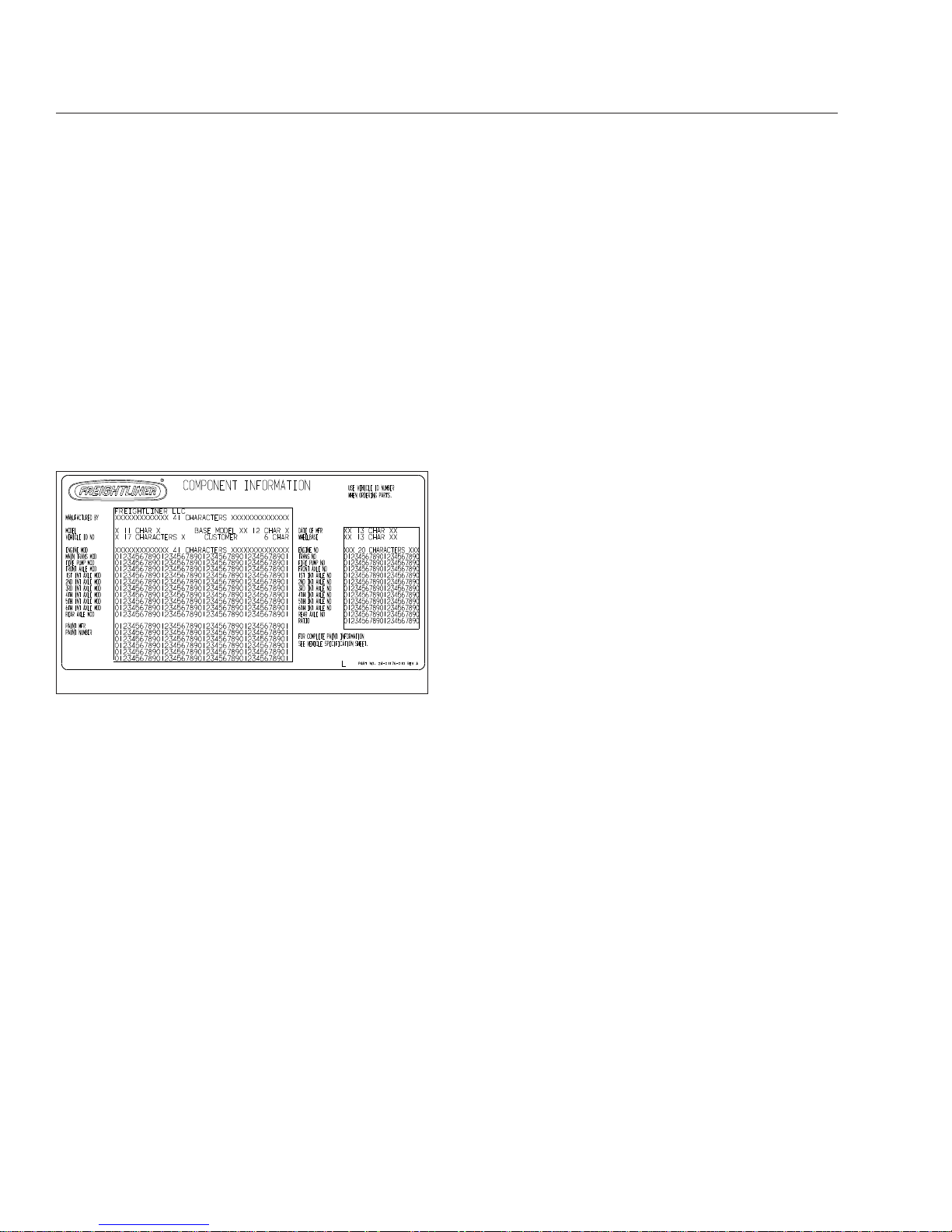
Component Information Label
NOTE: Labels shown in this chapter are examples only. Actual specifications may vary from
vehicle to vehicle.
The component information label lists the vehicle
model, identification number, and major component
models. It also lists the major assemblies and installations shown on the chassis specification sheet.
One copy of the component information label is attached to the inside of the glove box; another copy is
inside the rear cover of the Owner’s Warranty Infor-
mation for North America booklet. An illustration of
the label is shown in
Fig. 1.1.
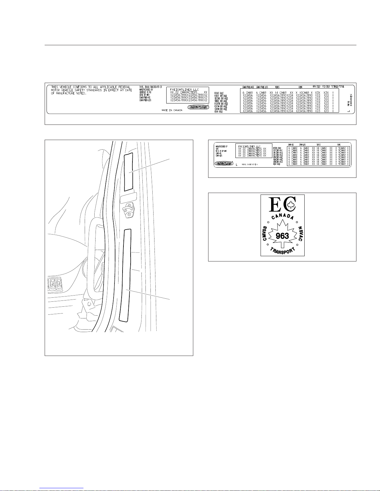
Federal Motor Vehicle Safety
Standard Labels
NOTE: Due to the variety of Federal Motor Vehicle Safety Standard (FMVSS) certification requirements, not all of the labels shown will apply
to your vehicle.
Tractors with or without fifth wheels purchased in the
U.S. are marked as certified by means of an FMVSS
certification label. See
Fig. 1.2. This label is attached
to the driver-side B-pillar, as shown in
Fig. 1.3.
The tire and rim portion of the FMVSS certification
label certifies suitable tire and rim combinations that
can be installed on the vehicle, for the given gross
axle weight rating. Tires and rims installed on the
vehicle at the time of manufacture may have a higher
load capacity than that certified by the tire and rim
label. If the tires and rims currently on the vehicle
have a lower load capacity than that shown on the
tire and rim label, then the tires and rims determine
the load limitations on each of the axles.
Trucks built without a cargo body that are intended
for service in the U.S. have an incomplete vehicle
certification label attached by the final-stage manufacturer. See
Fig. 1.4. This label will be attached to
the incomplete vehicle document included with the
vehicle, and certifies that the vehicle conforms to all
applicable FMVSS regulations in effect on the date of
completion.
Canadian Motor Vehicle Safety
Standard Labels
In Canada, tractors with fifth wheels are marked as
certified by means of a statement of compliance label
with the Canadian National Safety Mark attached to
the driver-side door frame B-pillar. See
Fig. 1.5.
Trucks built without a cargo body and tractors built
without a fifth wheel that are intended for service in
Canada have an incomplete vehicle certification label
attached to the driver-side B-pillar. After completion
of the vehicle, a complete certification label must be
attached by the final-stage manufacturer to certify
that the vehicle conforms to all applicable Canada
Motor Vehicle Safety Standard (CMVSS) regulations
in effect on the date of completion.
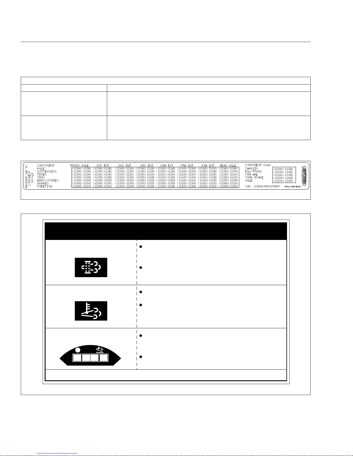
Component GWR Label
The component GWR label is located on the
passenger-side B-pillar. The label provides maximum
GWR ratings for each component.
See
Fig. 1.6 for a typical component GWR label.
Emissions Labels
Aftertreatment System Indicators
Label
Engines and vehicles manufactured after December
31, 2006 and domiciled in the U.S. or Canada are
required to meet all EPA regulations effective as of
the vehicle build date, and are equipped with an
emission aftertreatment system (ATS). Vehicles domiciled outside of the U.S. and Canada may not
have aftertreatment equipment, depending upon local
statutory emissions guidelines. See
Table 1.1.
02/20/2012 f080176
Fig. 1.1, Component Information Label
Vehicle Identification
1.1
Downloaded from www.Manualslib.com manuals search engine
A warning label on the driver-side visor contains important warning indicators in the instrument cluster
that pertain to the ATS. See
Fig. 1.7.
It is a violation of U.S. federal law to alter exhaust
plumbing, ATS, or other components in any way that
would bring the engine/vehicle out of compliance with
certification requirements [Ref: 42 U.S.C. S7522(a)
(3)]. It is the owner’s responsibility to maintain the
vehicle so that it conforms to EPA regulations.
EPA Noise Emission Control Label
A vehicle noise emission control label (Fig. 1.8)is
located on the driver-side B-pillar as shown in
Fig. 1.3. It is the owner’s responsibility to maintain
the vehicle so that it conforms to EPA regulations.
IMPORTANT: Certain Freightliner incomplete
vehicles may be produced with incomplete noise
control hardware. Such vehicles will not have a
vehicle noise emission control information label.
For such vehicles, it is the final-stage manufacturer’s responsibility to complete the vehicle in
conformity to U.S. EPA regulations (40 CFR Part
205) and label it for compliance.
02/20/2012 f080177
Fig. 1.2, Vehicle Certification Label
02/28/2012 f080182
1
2
1. EPA Noise Emission Control Label
2. FMVSS Certification Label
Fig. 1.3, Label Locations
f080180
02/28/2012
Fig. 1.4, Incomplete Vehicle Certification Label
f080024
10/10/2006
Fig. 1.5, Canadian National Safety Mark
Vehicle Identification
1.2
Downloaded from www.Manualslib.com manuals search engine
Applicable Emissions System Based on Build Date and EPA Regulations
Build Date Regulation: Emissions Components
January 1, 2010–December 31,
2012
EPA10 (reduce NOx emissions to 0.2 g/bhp-hr): Aftertreatment device (ATD)
containing a diesel particulate filter that traps soot and ash, with selective catalyst
reduction (SCR) technology that utilizes diesel exhaust fluid (DEF) to convert NOx to
nitrogen and water vapor.
From March 5, 2012
GHG14: Aerodynamic and fuel efficiency components including, but not limited to,
tires, cab/sleeper side extenders, chassis fairings, bumper, hood, vehicle speed
limiters, and idle reduction timers specifically designed to meet regulatory fuel
efficiency and greenhouse gas emissions standards.
Table 1.1, Applicable Emissions System Based on Build Date and EPA Regulations
02/20/2012 f080178
Fig. 1.6, Component GWR Label
DPF Regen Needed
Hot Exhaust
DEF Refill Needed
Diesel Particulate Filter (DPF)
regeneration is needed.
If flashing, regenerate as soon as
possible. Engine derate possible.
Hot exhaust can cause fire.
Keep flammables and people away
from exhaust.
Diesel Exhaust Fluid (DEF) level is
low. Engine derate likely.
Refill tank with certified DEF.
24−01656−000
IMPORTANT
DEF
11/30/2010 f080162
See operator’s manual for complete instructions.
Fig. 1.7, ATS Indicators
Vehicle Identification
1.3
Downloaded from www.Manualslib.com manuals search engine
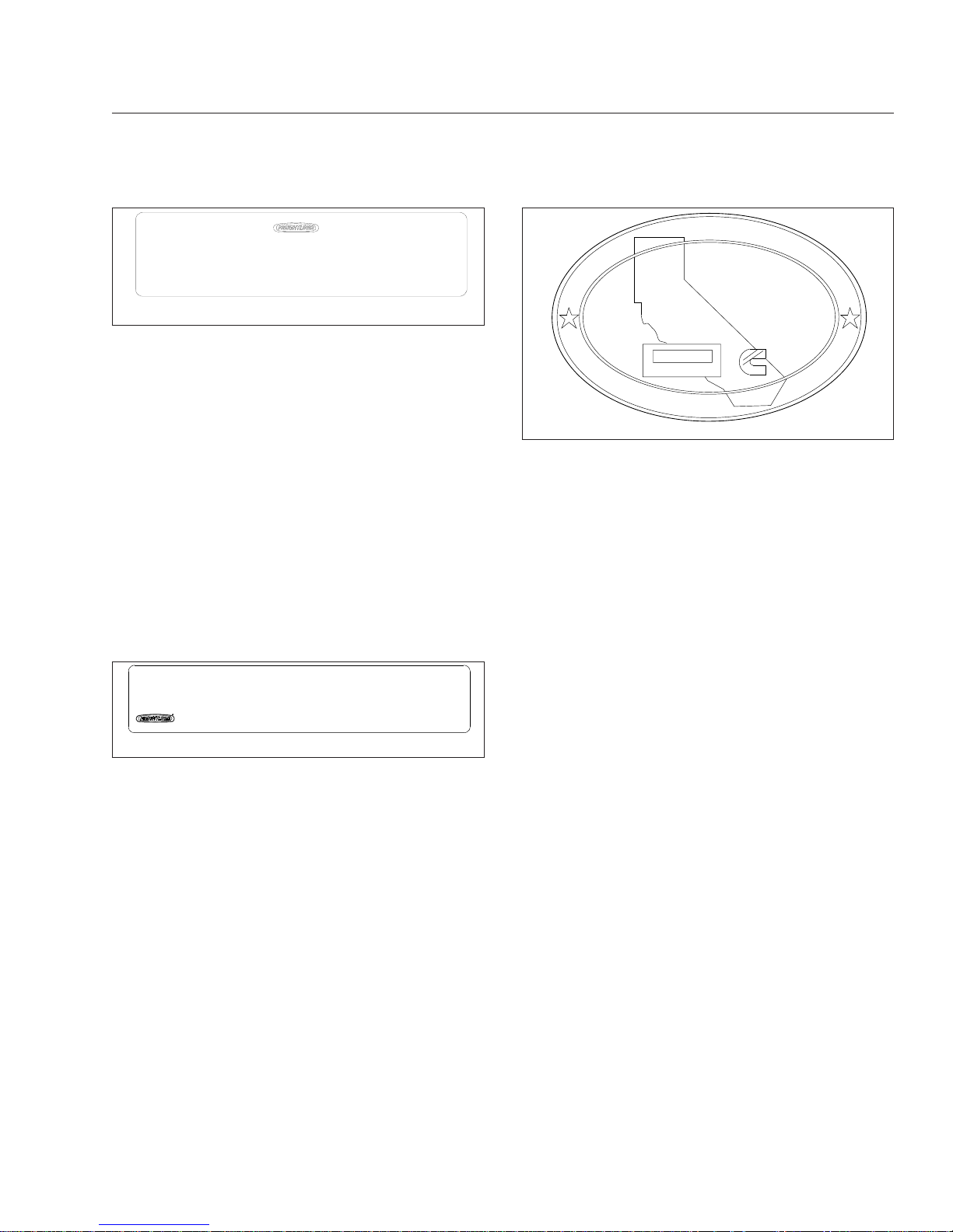
Vehicle Emission Control Information
Label
Model year 2013 and later vehicles meet additional
requirements as specified by federal greenhouse gas
and fuel efficiency regulations (GHG14). These vehicles are equipped with components that increase
fuel efficiency and reduce GHG emissions. Components may include, but are not limited to, low-rolling
resistance tires; aerodynamic devices such as hood,
cab side extenders, and fuel tank fairings; vehicle
speed limiters; and idle shutdown timers.
A Vehicle Emission Control Information Label is located on the driver-side door. See
Fig. 1.9.Itisthe
owner’s responsibility to maintain the vehicle so that
it conforms to EPA and NHTSA regulations.
Certified Clean Idle Label
The California Air Resources Board (CARB) requires
model year 2008 and newer heavy-duty diesel engines to be equipped with a non-programmable engine shutdown system that automatically shuts down
the engine after five minutes of idling in order to limit
emissions of particulate matter and NOx.
Certified vehicles are equipped with a label placed
near the bottom edge of the driver-side door. See
Fig. 1.10.
10/06/98
f080026
24−00273−020
VEHICLE NOISE EMISSION CONTROL INFORMATION
FREIGHTLINER CORPORATION
THIS VEHICLE CONFORMS TO U.S. EPA REGULATIONS FOR NOISE EMISSION
APPLICABLE TO MEDIUM AND HEAVY TRUCKS.
THE FOLLOWING ACTS OR THE CAUSING THEREOF BY ANY PERSON ARE PROHIBITED BY
THE NOISE CONTROL ACT OF 1972:
A. THE REMOVAL OR RENDERING INOPERATIVE, OTHER THAN FOR PURPOSES OF
MAINTENANCE, REPAIR, OR REPLACEMENT, OF ANY NOISE CONTROL DEVICE OR
ELEMENT OF DESIGN (LISTED IN THE OWNER’S MANUAL) INCORPORATED INTO THIS
VEHICLE IN COMPLIANCE WITH THE NOISE CONTROL ACT.
B. THE USE THIS VEHICLE AFTER SUCH DEVICE OR ELEMENT OF DESIGN HAS
BEEN REMOVED OR RENDERED INOPERATIVE.
DATE OF MANUFACTURE
01/96
Fig. 1.8, Vehicle Noise Emission Control Label
f080181
02/29/2012
MANUFACTURED BY:
VIN:
VEH FAMILY CD:
GVWR−KG
GVWR−LBS
REGULATORY CLASS:
EMISSION CONTROL IDENTIFIERS:
DATE OF MANUFACTURE:
VEHICLE EMISSION CONTROL INFORMATION
THIS VEHICLE COMPLIES WITH U. S. EPA REGULATIONS FOR XXXX HEAVY DUTY VEHICLES.
SEE OWNER’S MANUAL FOR PROPER MAINTENANCE OF THIS VEHICLE. U PART NO. 24−01177−060 REV A
Fig. 1.9, Vehicle Emission Control Information Label
CERTIFIED
CLEAN IDLE
02/20/2012 f080179
Fig. 1.10, CARB Clean Idle Label
Vehicle Identification
1.4
Downloaded from www.Manualslib.com manuals search engine

2
Vehicle Access
Door Locks and Handles ........................................................... 2.1
Cab Entry and Exit ................................................................ 2.2
Back-of-Cab Access ............................................................... 2.4
Hood Opening and Closing ......................................................... 2.5
Downloaded from www.Manualslib.com manuals search engine
Door Locks and Handles
One key operates the ignition switch and all of the
door locks.
IMPORTANT: Each key is numbered. Record
the number so a duplicate key can be made, if
needed.
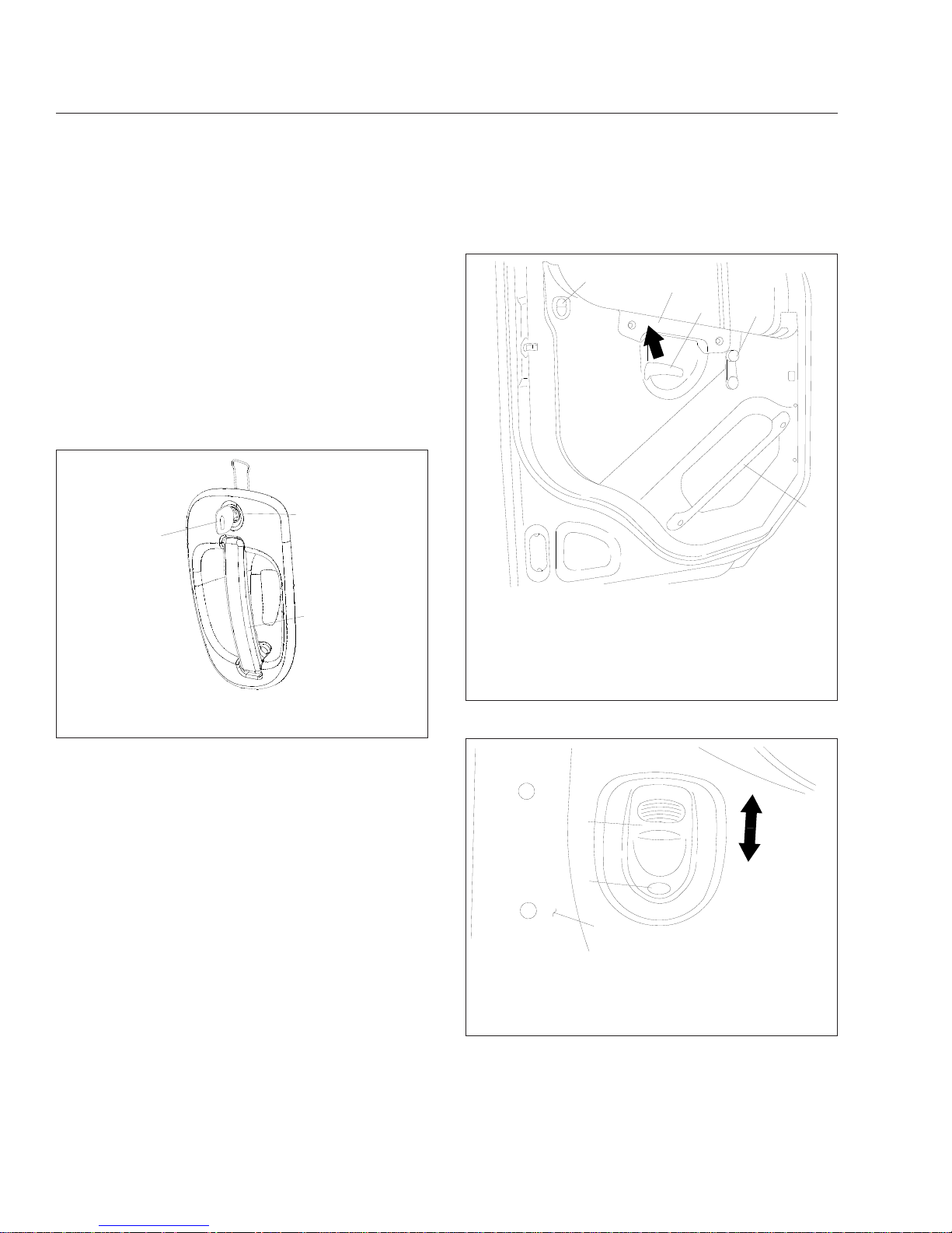
To unlock the driver’s door from outside the cab, insert the key in the lockset and turn it one-quarter turn
clockwise (
Fig. 2.1). To remove the key, turn it coun-
terclockwise to its original position. Pull out on the
door pull handle to open the door.
To unlock the passenger’s door from outside the cab,
insert the key in the lockset and turn it one-quarter
turn counterclockwise. Turn the key clockwise to the
original position to remove it.
To open the door from the inside, lift up on the door
lever. This will unlatch the door whether or not it is
locked. See
Fig. 2.2.
NOTE: The cab door locks can be operated
when the doors are open.
To lock a door from outside the cab, insert the key in
the lockset and turn it in the direction opposite to the
unlocking direction (counterclockwise for the driver’s
door, clockwise for the passenger’s door). Close the
door if it is open.
To lock either door from inside the cab, push the lock
button downwards (
Fig. 2.3). To unlock the door
without unlatching it, push the lock button upwards. A
red dot will show below the lock button when it is
unlocked.
10/22/2001
f720397
1
2
3
1. Key
2. Lock
3. Door Pull Handle
Fig. 2.1, Exterior Door Handle
10/25/2001
f720398
1
2
3
4
5
To open the door from the inside, lift up on the door lever
(arrow).
1. Lock Button
2. Armrest/Handle
3. Door Lever
4. Window Crank
5. Inner Door Grab
Handle (optional)
Fig. 2.2, Door Interior
10/24/2001
f720401
1
2
3
Move the button down to lock, and up to unlock (arrows).
The door is unlocked when the red dot shows.
1. Door
2. Lock Button
3. Red Dot
Fig. 2.3, Door Lock Button
Vehicle Access
2.1
Downloaded from www.Manualslib.com manuals search engine

Cab Entry and Exit
For ease of entry and exit, there are three grab
handles, one on the A-pillar, one on the inner B-pillar,
and an optional one on the inside of the door. In addition, the steering wheel may be used to provide
secure handholds. There are at least two access
steps to provide secure footholds.
NOTE: The A-pillar grab handle is not installed
on the driver’s side.
The grab handles, access steps, and steering wheel
are all part of the cab access system. Use these
"helping hands" when getting into, or out of, the cab.
They will increase your security and comfort.
Entering from the Driver’s Side
To enter the cab on the driver’s side, use the grab
handles and access steps as follows:
1.
Open the driver-side door and place anything
that you are carrying in the cab.
2.
Grasp the B-pillar grab handle with your right
hand. See
Fig. 2.4.
3.
Grasp the door grab handle with your left hand.
4.
Place your right foot on the bottom step, and pull
yourself up.
5.
Place your left foot on the top step.
6.
Grasp the steering wheel with your left hand, and
step up.
7.
Step into the cab with your right foot first, and
grasp the steering wheel with your right hand.
Exiting from the Driver’s Side
To exit the cab from the driver’s side, use the grab
handles and access steps as follows:
IMPORTANT: Do not attempt to exit the cab
while carrying any items in your hands.
1.
If you wish to take any items with you out of the
cab, place them in an accessible location on the
seat or cab floor. Make sure they will not get in
your way as you exit.
WARNING
Always face in when exiting the cab. Do not attempt to exit with your back to the cab, as you
would going down a flight of stairs. It is easier to
slip or lose your balance. If you slip when exiting
in this way, there is a greater likelihood of personal injury.
2.
Grasp the steering wheel with both hands, place
your left foot on the top step, then stand on the
threshold facing into the cab. See
Fig. 2.4.
3.
Using your right hand, grasp the B-pillar grab
handle.
4.
Move your right foot to the bottom step.
12/20/2010 f720726
1
2
3
4
5
6
7
1. Bottom Step
2. Top Step
3. Door Grab Handle
4. Armrest
5. Steering Wheel
6. Sidewall Grab Handle
7. B-Pillar Grab Handle
Fig. 2.4, Cab Access System, Driver’s Side
Vehicle Access
2.2
Downloaded from www.Manualslib.com manuals search engine

5.
Move your left hand to the door grab handle.
6.
Step to the ground with your left foot first.
7.
Retrieve from the cab any items that you wish to
take with you.
Entering from the Passenger’s Side
To enter the cab on the passenger side, use the grab
handles and access steps as follows:
1.
Open the passenger-side door and place anything that you are carrying in the cab.
2.
Using your left hand, grasp the B-pillar grab
handle. See
Fig. 2.5.
3.
Using your right hand, grasp the door grab
handle.
4.
Place your left foot on the bottom step.
5.
Place your right foot on the top step.
6.
Move your right hand to the A-pillar grab handle.
7.
Place your left foot on the top step, then move
your left hand to the A-pillar grab handle.
8.
Step into the cab with your left foot first.
Exiting from the Passenger’s Side
To exit the cab from the passenger side, use the
grab handles and access steps as follows:
IMPORTANT: Do not attempt to exit the cab
while carrying any items in your hands.
1.
If you wish to take any items with you out of the
cab, place them in an accessible location on the
seat or cab floor. Make sure they will not get in
your way as you exit.
WARNING
Always face in when exiting the cab. Do not attempt to exit with your back to the cab, as you
would going down a flight of stairs. It is easier to
slip or lose your balance. If you slip when exiting
in this way, there is a greater likelihood of personal injury.
2.
Grasp the A-pillar grab handle with both hands,
then place your right foot on the top step while
standing up from the seat facing inward. See
Fig. 2.5.
3.
Place your left foot on the top step.
4.
Move your left hand to the B-pillar grab handle.
5.
Move your left foot to the bottom step.
6.
Move your right hand to the door grab handle.
7.
Step to the ground with your right foot first.
8.
Retrieve from the cab any items that you wish to
take with you.
12/17/2010 f720727
1
2
3
4
5
6
7
1. Bottom Step
2. Top Step
3. B-Pillar Grab Handle
4. ATD Grab Handle
(optional)
5. A-Pillar Grab Handle
6. Armrest
7. Door Grab Handle
Fig. 2.5, Cab Access System, Passenger’s Side and
Back of Cab
Vehicle Access
2.3
Downloaded from www.Manualslib.com manuals search engine

Back-of-Cab Access
WARNING
External surfaces of the exhaust system remain
hot after the engine has been shut down. When
accessing the back of the cab or sleeper, do not
touch any part of the exhaust system, or severe
burns could occur.
When trailer air and electrical connections cannot be
reached conveniently from the ground, Federal Motor
Carrier Safety Regulations require commercial carriers to provide back-of-cab access.
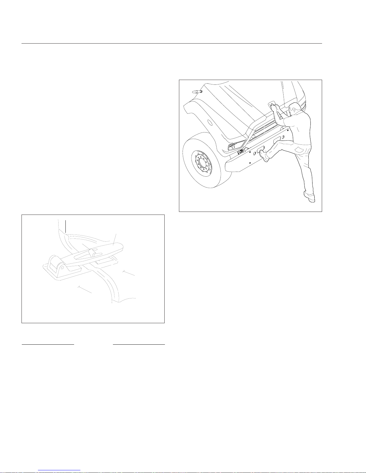
Optional grab handles are mounted on each cab
sidewall, or on the left sidewall only. See
Fig. 2.6.
Steps are mounted either on the fuel tank(s) or on
metal brackets. When a deck plate is necessary, it is
mounted across the top of the frame rails.
IMPORTANT: Climb onto, and down from, backof-cab access facing in toward the vehicle, as
you would on a ladder. Do not climb up or down
facing out away from the vehicle.
WARNING
Wet or dirty shoe soles greatly increase the
chance of slipping or falling. If your soles are wet
or dirty, be especially careful when climbing
onto, or leaving, the back-of-cab area.
Always maintain three-point contact with the
back-of-cab access supports while entering and
exiting the back-of-cab area. Three-point contact
means both feet and one hand, or both hands
and one foot, on the grab handles, steps, and
deck plates. Other areas are not meant to support back-of-cab access, and grabbing or stepping in the wrong place could lead to a fall, and
personal injury.
Be careful not to get hands or feet tangled in
hoses or other back-of-cab equipment. Carelessness could cause a person to trip and fall, with
possible injury.
Climbing Up to Back-of-Cab
When climbing onto the deck plate, do the following:
1.
Grasp the sidewall grab handle with both hands.
Reach up as far as is comfortable.
2.
Place one foot on the bottom step and pull yourself up.
3.
Place your other foot on the top step.
4.
Move your lower hand to a higher position on the
grab handle.
5.
Step onto the deck plate.
Climbing Down from Back-of-Cab
To climb down from the back-of-cab area:
1.
Grasp the sidewall grab handle with both hands.
2.
Step one foot at a time onto the top step.
3.
Move your upper hand to a lower position on the
grab handle.
4.
Move one foot to the bottom step.
12/17/2010 f602442
1
1
2
3
1. Steps
2. Grab Handle
3. Deck Plate
Fig. 2.6, Back-of-Cab Access Supports (typical)
Vehicle Access
2.4
Downloaded from www.Manualslib.com manuals search engine
5.
Move your upper hand to a lower position on the
grab handle.
6.
Step to the ground with your upper foot first.
Hood Opening and Closing
The hood can be raised to a full-open position. A
strut helps you to raise the hood, and to lower it to
the operating position. Hood restraint cables prevent
the hood from overtravel. The hood strut limits the
closing speed. In the operating position, the hood is
secured to the cab-mounted cowl by a hold-down
latch on each side of the hood.
To Tilt the Hood
1.
Apply the parking brakes.
2.
Release both hood hold-down latches by pulling
the ends outward. See
Fig. 2.7.
NOTICE
Do not let the hood free-fall to the full-open position. To do so could cause damage to the hood
or hood straps.
3.
Standing in front of the hood, raise the rear of
the hood upward until it reaches the over-center
position (45 degrees from vertical). See
Fig. 2.8.
Then slowly bring it to a stop.
To Return the Hood
1.
Push the hood over center.
2.
As the hood goes over center, the strut automatically slows its rate of descent. If needed, you
can also slow its descent with your hand.
3.
Make sure the hood is flush with the cowl, then
secure the hood by engaging both hood holddown latches.
IMPORTANT: Make sure that both hold-down
latches are fully engaged before operating the
vehicle.
10/24/2001
f880555
1
2
3
4
1. Fender
2. Latch Hook
3. Latch Handle
4. Cowl
Fig. 2.7, Hood Hold-Down Latch
02/02/2011 f602441
Fig. 2.8, Hood Tilting
Vehicle Access
2.5
Downloaded from www.Manualslib.com manuals search engine

3
Electrical System
Vehicle Power Distribution .......................................................... 3.1
Load Disconnect Switch ............................................................ 3.1
Battery Access ................................................................... 3.2
Downloaded from www.Manualslib.com manuals search engine
Vehicle Power Distribution
WARNING
Do not attempt to modify, add, splice, or remove
electrical wiring on this vehicle. Doing so could
damage the electrical system and result in a fire
that could cause serious personal injury or property damage.
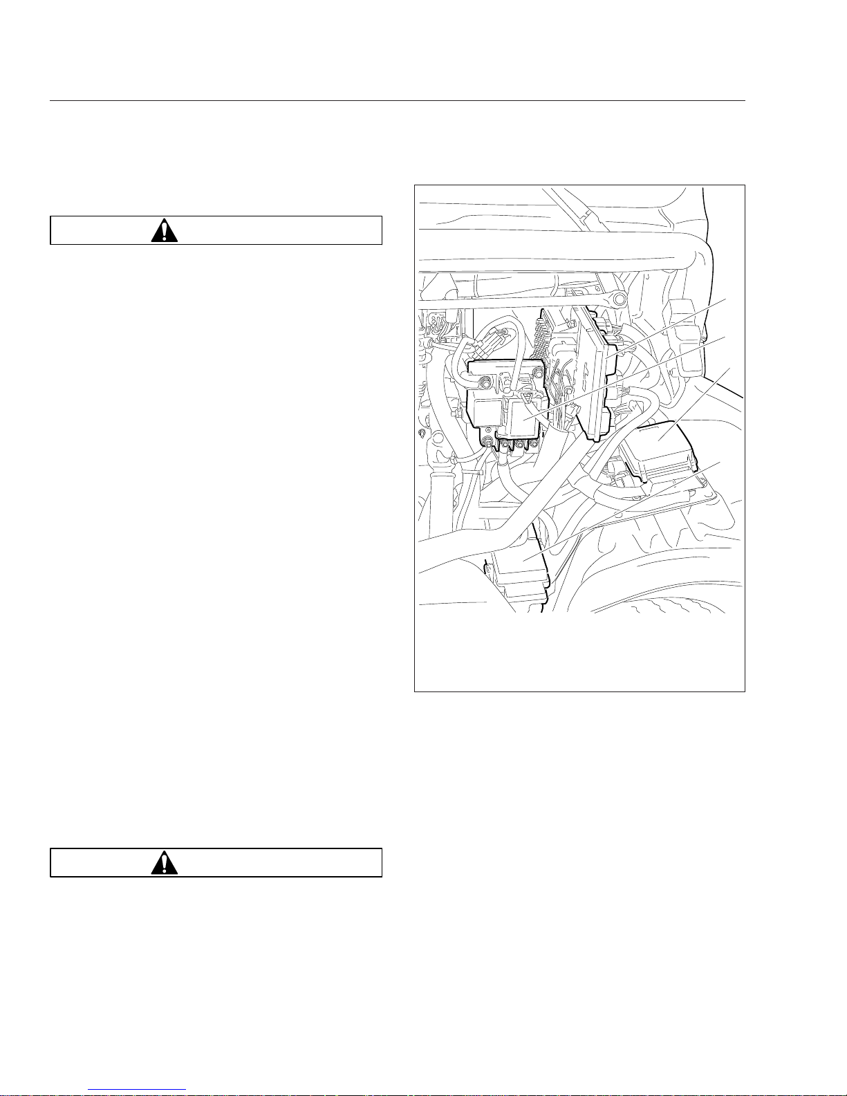
Power Distribution Modules
The main power distribution module (PDM) is located
under the hood on the driver-side splash shield. See
Fig. 3.1. The PDM contains the circuit breakers and
fuses required to protect the vehicle cab circuits. The
label on the inside of the PDM cover identifies typical
set of fuses.
The powertrain PDM (PTPDM) is mounted in the engine compartment near the main PDM. See
Fig. 3.1.
It controls power to the engine, aftertreatment system
(ATS), transmission, and other powertrain-related
circuits.
The auxiliary PDM is located on the cab back wall,
behind the driver’s seat. See
Fig. 3.2. The auxiliary
PDM may contain the auxiliary powernet distribution
box, the body lighting PDM, and the trailer PDM, if
so equipped.
Main Powernet Distribution Box
The main powernet distribution box (PNDB) is
mounted on the cab frontwall next to the bulkhead
module. See
Fig. 3.1. It supplies power to the
PTPDM and main PDM, and powers other vehicle
functions, including the clock. The label on the PNDB
fuse cover identifies typical circuits.
An auxiliary PNDB may also be located on the cab
back wall, behind the driver’s seat.
Load Disconnect Switch
WARNING
Turning the load disconnect switch to the OFF
position does not disconnect the connection between the battery and the starter. To work on the
vehicle safely, the negative leads must be disconnected from the battery.
The optional load disconnect switch (
Fig. 3.3)is
used to avoid excessive draw on the battery when
the vehicle is parked for an extended period of time.
When the load disconnect switch is set to OFF, it signals the PNDB to disconnect battery power to powertrain and accessory loads.
The load disconnect switch is mounted in one of two
locations:
•
inside the cab on the left side of the driver’s
seat;
•
on/near the battery box;
IMPORTANT: The ignition should be turned OFF
before using the load disconnect switch.
11/24/2010 f545704
1
2
3
4
1. Bulkhead Module
2. Powernet Distribution Box (PNDB)
3. Main Power Distribution Module (PDM)
4. Powertrain PDM (PTPDM)
Fig. 3.1, Power Distribution Module Locations
Electrical System
3.1
Downloaded from www.Manualslib.com manuals search engine
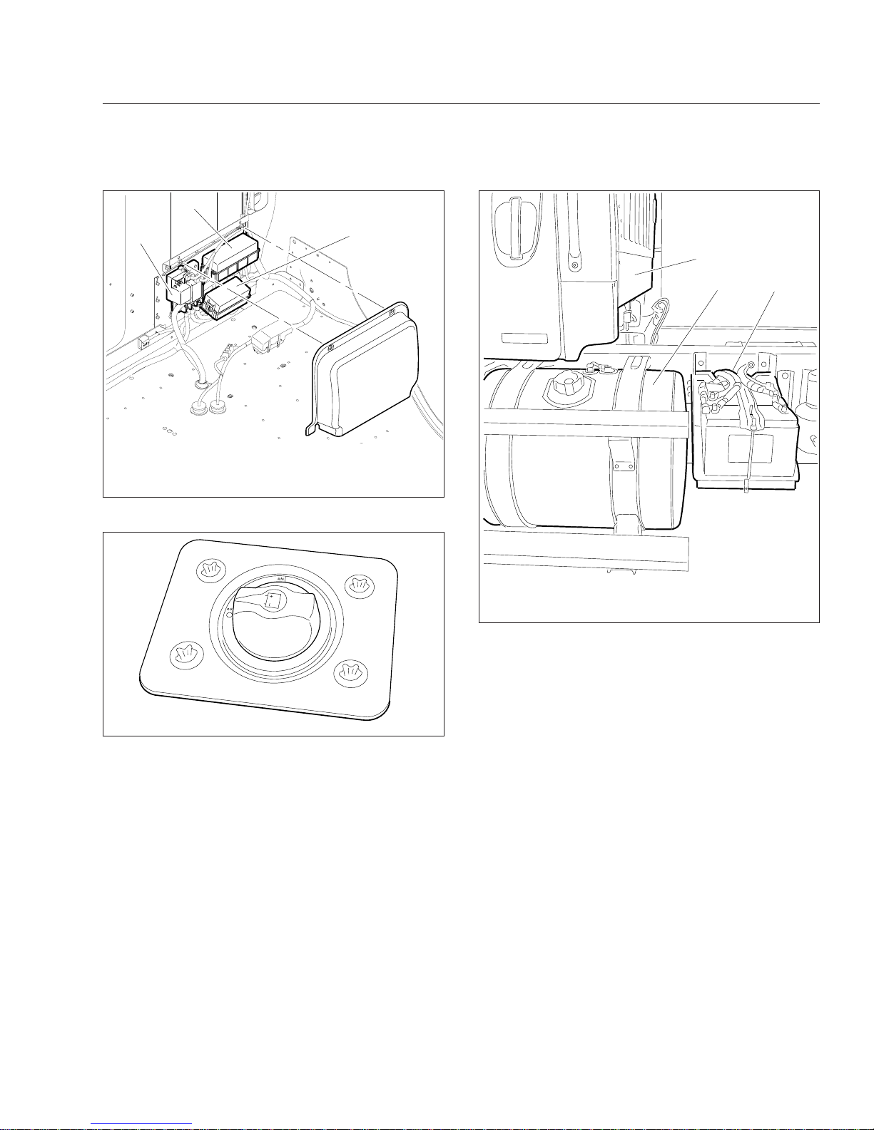
Battery Access
The batteries on a standard vehicle are located on
the driver’s side, behind the fuel tank. See Fig. 3.4.
To access the batteries, pull the cotter pin from the
latch on the battery box cover, then release the latch
and lift off the cover.
12/15/2010 f545719
1
2
3
1. Auxiliary PNDB
2. Trailer PDM
3. Body Lighting PDM
Fig. 3.2, Auxiliary Power Distribution Module
05/13/2009 f545527
Fig. 3.3, Load Disconnect Switch
12/03/2010 f545714
1
2
3
1. Back-of-Cab
2. Fuel Tank
3. Battery Compartment
Fig. 3.4, Standard Battery Compartment Location
Electrical System
3.2
Downloaded from www.Manualslib.com manuals search engine

4
Instruments
Instrumentation Control Unit ........................................................ 4.1
Warning and Indicator Lights ........................................................ 4.2
Driver Message Center ............................................................ 4.7
Instruments ...................................................................... 4.8
Overhead Instrument Panel ........................................................ 4.12
Downloaded from www.Manualslib.com manuals search engine
Instrumentation Control Unit
The instrumentation control unit (ICU) provides the
driver with engine and vehicle information. It is comprised of standard and optional gauges, an audible
warning, a driver message center, and a lightbar containing warning and indicator lamps (also known as
telltales). Warning and indicator lamps illuminate in
red (danger), amber (caution), green (status advisory), or blue (high-beam headlights active).
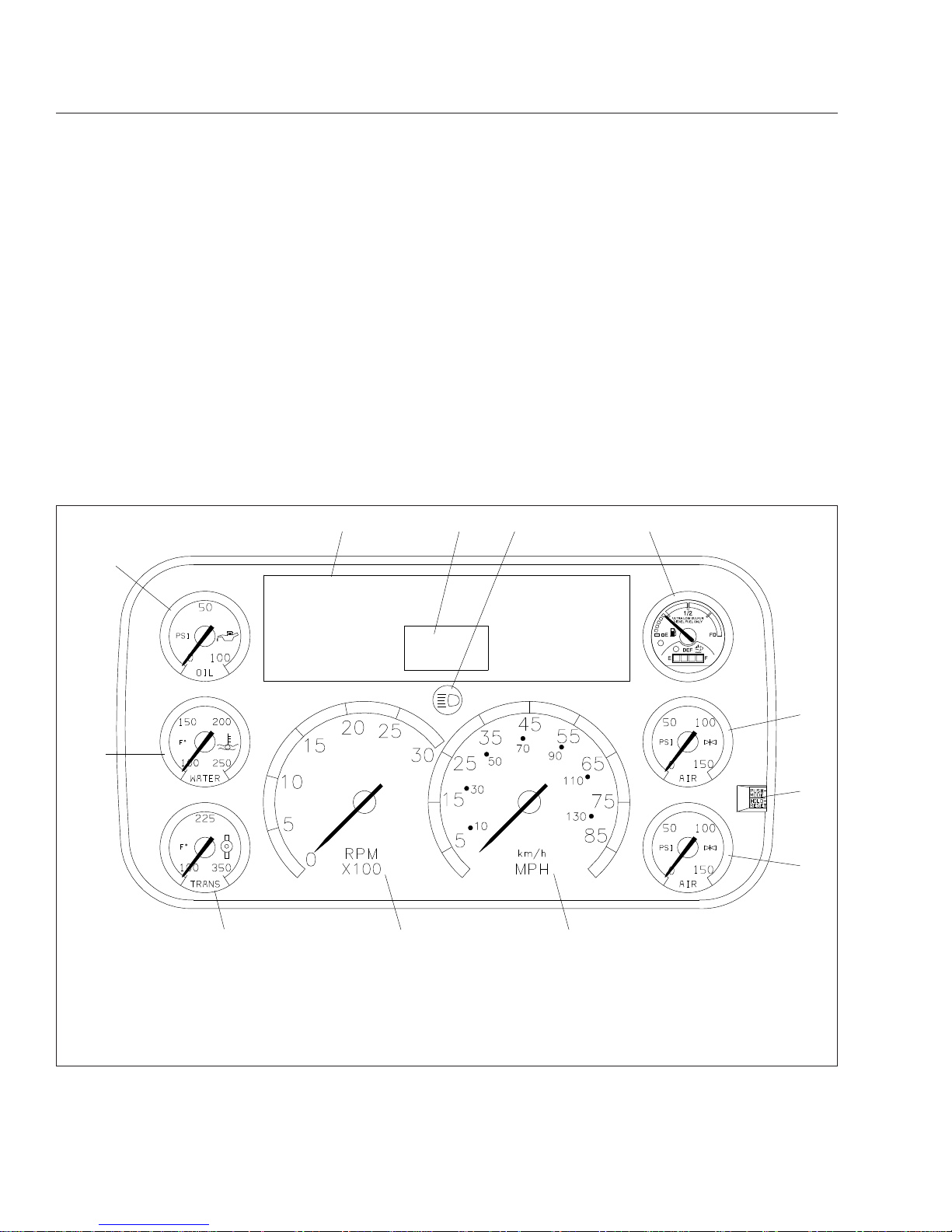
Figure 4.1 shows a typical ICU3 instrument cluster.
The following headings in this chapter provide additional information and operating instructions for ICU
components:
•
"Warning and Indicator Lights"
•
"Instruments"
•
"Driver Message Center"
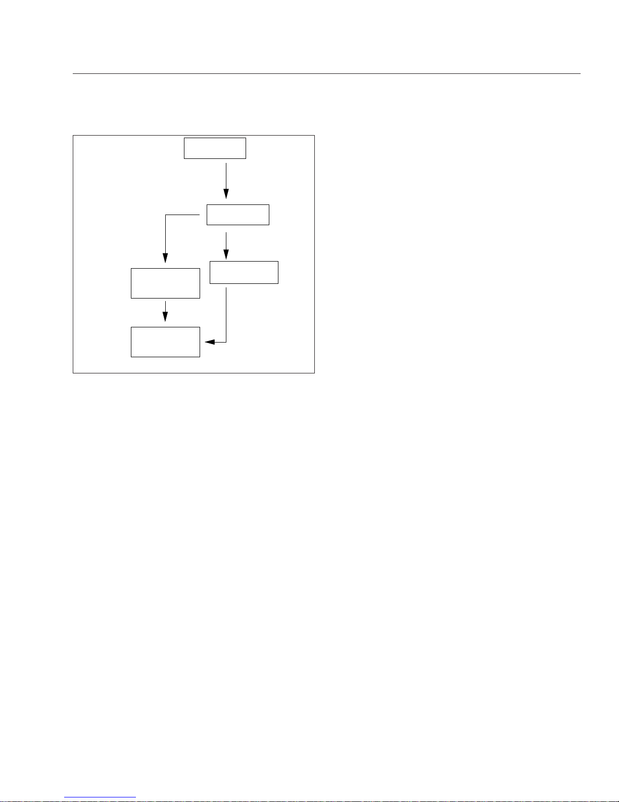
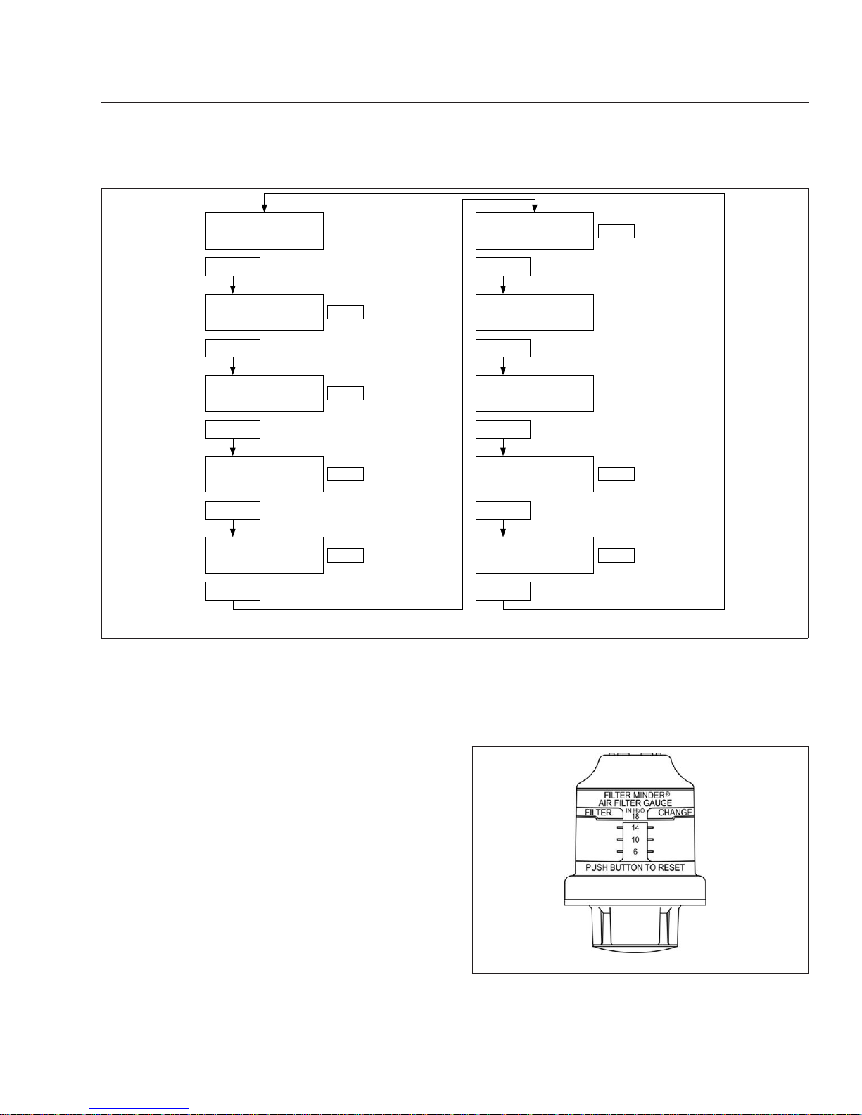
Ignition Sequence
When the ignition is turned on, the ICU runs a selfcheck. See Fig. 4.2. Observing the ignition sequence
is a good way to ensure the ICU is functioning
properly.
IMPORTANT: Do not crank the engine until the
ICU self-check is complete.
When the ignition is turned on, the following actions
should occur:
f610525a
1
234 5
6
7
8
12
11 10 9
09/10/2009
NOTE: This instrument cluster is shown with the U.S. speedometer, which shows miles per hour (mph) more prominently
than kilometers per hour (km/h).
1. Engine Oil Pressure Gauge
2. Lightbar
3. Driver Message Center
4. Headlight High-Beam Indicator
5. Fuel/DEF Level Gauge
6. Primary Air Pressure Gauge
7. Mode/Reset Button
8. Secondary Air Pressure Gauge
9. Speedometer (U.S. version)
10. Tachometer
11. Transmission Temperature Gauge
12. Coolant Temperature Gauge
Fig. 4.1, Typical ICU3 (U.S. shown)
Instruments
4.1
Downloaded from www.Manualslib.com manuals search engine
•
electronic gauges complete a full sweep of
their dials
•
some warning and indicator lamps illuminate,
then are extinguished
•
audible alert sounds until sufficient air pressure
builds up in the primary and secondary air systems
•
DEF level indicator illuminates all segments
green, then turns them off one at a time before
turning the leftmost segment amber, then red
•
software revision level of the ICU is displayed
on the driver message center, followed by active faults
NOTE: Air gauges do not complete a sweep of
their dials during the ignition sequence.
IMPORTANT: If any red or amber warning and
indicator lamps, or telltales, do not illuminate
during the ICU self-check, take the vehicle to an
authorized Freightliner service facility as soon
as possible. If any of the red or amber telltales
or do not go out after the self-check completes,
use
Table 4.1 to determine if the lamp illumi-
nated indicates a problem requiring service.
If the ICU receives active fault codes, it displays
them one after the other until the parking brake is
released or the ignition is turned off. Once the parking brake is completely released, the ICU displays
the odometer. If there are no active faults, the ICU
displays the odometer after the self-check completes.
NOTE: If active faults are present, take the vehicle to an authorized Freightliner service facility
as soon as possible.
Audible Alerts
An audible alert sounds during the ignition sequence
and whenever one of the following conditions exists:
•
Engine oil pressure falls below the minimum
preset value.
•
Coolant temperature rises above the maximum
preset value.
•
Air pressure falls below about 70 psi (483
kPa).
•
Parking brake is set with the vehicle moving
faster than two miles per hour.
•
System voltage falls below 12 volts.
•
Door is open with the headlights on and the
parking brake off.
•
Driver seat belt is not fastened with the parking
brake off (optional).
•
Outside temperature falls below 35°F (1.7°C)
(optional).
Warning and Indicator Lights
There can be up to 28 telltales installed in the ICU. If
an optional lamp is not requested, the position is
blank.
See
Table 4.1 for a list of standard and commonly
used warning and indicator lamps.
Warning and indicator lamps illuminate in red (danger), amber (caution), green (status advisory), or
blue (high-beam headlights active).
IGNITION SWITCH
PARKING BRAKE
RELEASED
IF NO FAULTS
WERE DETECTED
IF FAULT DETECTED
APU 190
123456.7
12.3 VOLTS
123456.7
12.3 VOLTS
MI
MI
01/18/2012 f040420c
PARKING BRAKE
RELEASED
TURNED TO ON
ICU PERFORMS
SELF−TEST
Fig. 4.2, Ignition Sequence
Instruments
4.2
Downloaded from www.Manualslib.com manuals search engine
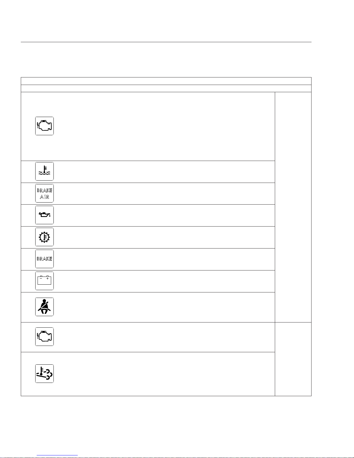
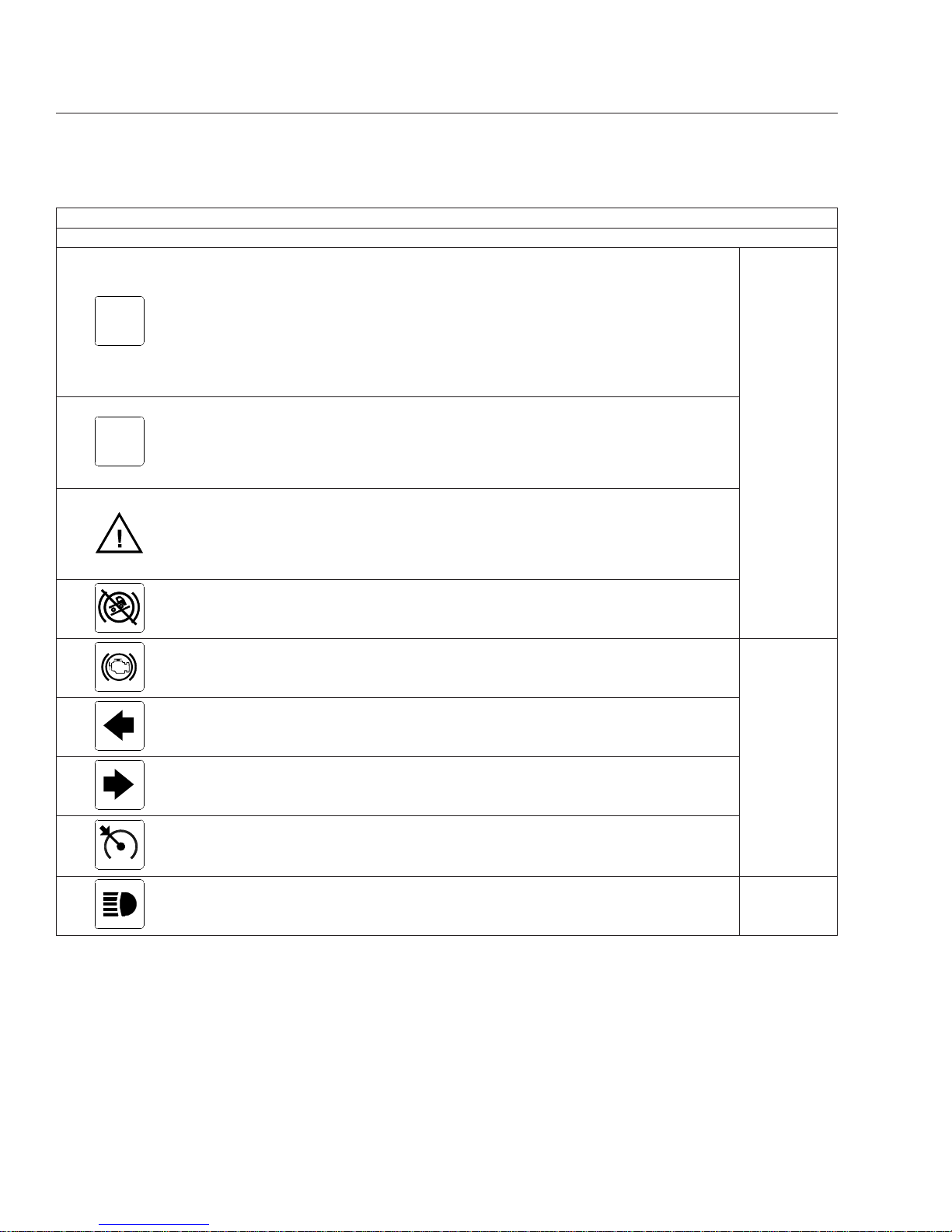
Common Warning and Indicator Lamps
Lamp Description Color
STOP
STOP Engine
*
Indicates a serious fault that requires engine shutdown
immediately. The engine protection system will reduce the
maximum engine torque and speed, and, if the condition
does not improve, will shut down the engine within 30 to 60
seconds.
Safely bring the vehicle to a stop on the side of the road
and shut down the engine as soon as the red light is seen.
If the engine shuts down while the vehicle is in a
hazardous location, turn the key to the OFF position for
a few seconds, then restart the engine and move the
vehicle to a safer location.
Red
High Coolant Temperature
Indicates the coolant temperature is above the maximum
allowable temperature.
Low Air Pressure
Indicates air pressure in the primary or secondary reservoir
has dropped below approximately 70 psi (483 kPa).
Low Engine Oil Pressure
Indicates the engine oil pressure is below the minimum
allowable pressure.
Transmission Overheat Indicates high transmission temperature.
Parking Brake Indicates the parking brake is engaged.
Low Battery Voltage Indicates that battery voltage is 11.9 volts or less.
Unfastened Seat Belt
Activates with an audible alert when the system detects that
the parking brake is off and the driver seat belt is not
fastened on some vehicles. On other vehicles, this lamp
illuminates for 15 seconds when the ignition is first turned
on.
CHECK
CHECK Engine
*
Indicates an engine condition (low oil pressure, low coolant
level, high coolant temperature, high DPF soot level, or
uncontrolled DPF regeneration) that requires correction.
Correct the condition as soon as possible. If the condition
worsens, the STOP engine lamp will illuminate.
Amber
High Exhaust System
Temperature (HEST)
*
Slow (10-second) flashing indicates a regeneration (regen)
is in progress.
IMPORTANT: When the HEST lamp is illuminated, do
not park the vehicle near flammable material.
Solid illumination indicates high exhaust temperatures at the
outlet of the tail pipe when speed is below 5 mph (8 km/h).
Instruments
4.3
Downloaded from www.Manualslib.com manuals search engine
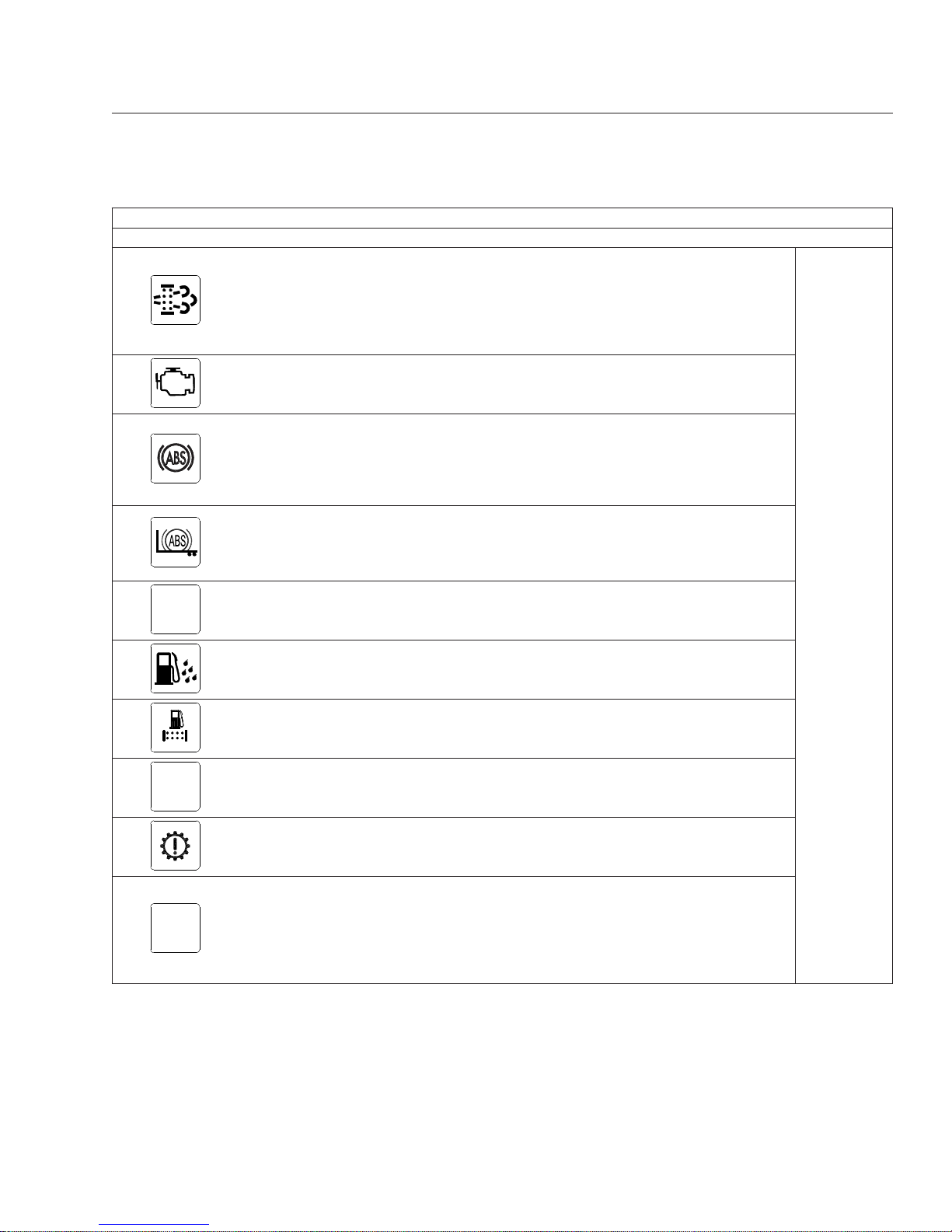
Common Warning and Indicator Lamps
Lamp Description Color
Diesel Particulate Filter
(DPF) Status
Solid illumination indicates a regen is required. Change to a
more challenging duty cycle (such as highway driving ) to
raise exhaust temperatures for at least twenty minutes, or
perform a parked regen.
Blinking indicates that a parked regen is required
immediately. An engine derate and shutdown will occur.
Amber
Malfunction Indicator
Lamp (MIL)
Indicates an emissions-related fault. See the engine
operation manual for details.
Vehicle ABS
Momentary illumination indicates the vehicle ABS is
engaged.
Solid illumination indicates a problem with the vehicle ABS.
Repair the ABS immediately to ensure full braking
capability.
Trailer ABS
Momentary illumination indicates the trailer ABS is engaged.
Solid illumination indicates a problem with the trailer ABS.
Repair the ABS immediately to ensure full braking
capability.
NO
CHARGE
No Charge
Indicates the alternator is not properly powering the
electrical system.
Water in Fuel
Indicates the fuel may contain water. Drain any water
collected in the fuel/water separators.
Fuel Filter Restriction Indicates the fuel filter is clogged and requires service.
IDLE
MGMT
Optimized Idle Indicates optimized idle is enabled.
Check Transmission Indicates an undesirable transmission condition.
WAIT
TO START
Wait To Start (EPA10)
Indicates that the system is preventing the starter from
cranking. This can occur when the ignition switch is turned
to START before the gauge sweep has completed, or if the
starter has overheated.
Turn the ignition switch back to ON, wait for the lamp to go
out, then turn the ignition switch to START again.
Instruments
4.4
Downloaded from www.Manualslib.com manuals search engine
Common Warning and Indicator Lamps
Lamp Description Color
START
BLOCKED
Start Blocked (GHG14)
Indicates that the system is preventing the starter from
cranking. This can occur when the ignition switch is turned
to START before the gauge sweep has completed, or if the
starter has overheated.
NOTE: Illumination of the Start Blocked lamp does not
indicate a problem with the starter.
Turn the ignition switch back to ON, wait for the lamp to go
out, then turn the ignition switch to START again.
Amber
WHEEL
SPIN
Wheel Spin
Flashing indicates the ATC system is active, or the ATC
button has been pressed to allow wheel slip.
Solid illumination indicates a problem with the ATC system.
Repair the ATC system immediately to ensure full braking
capability.
Roll Stability
Momentary illumination indicates that a stability event has
occurred.
On vehicles that are also equipped with ATC, flashing
indicates the ATC button has been pressed to allow wheel
slip.
Hill Start Aid (HSA)
Override
Indicates the HSA switch has been pressed to override the
hill start assist feature.
Engine Brake Indicates the engine brake is enabled.
Green
Left-Turn Signal
Flashing indicates the outside left-turn signal lights are
activated.
Right-Turn Signal
Flashing indicates the outside right-turn signal lights are
activated.
Cruise Control
Indicates the cruise control is enabled.
NOTE: The ICU4Me does not have a green cruise control
telltale.
High-Beam Headlights Indicates the high-beam headlights are on. Blue
*
See Fig. 4.3 for an explanation of the aftertreatment system (ATS) warning indicators, and actions required to avoid further engine protection steps.
Table 4.1, Common Warning and Indicator Lamps
Instruments
4.5
Downloaded from www.Manualslib.com manuals search engine

Engine Protection System
WARNING
When the red STOP engine lamp illuminates,
most engines are programmed to shut down automatically within 30 seconds. The driver must
immediately move the vehicle to a safe location
at the side of the road to prevent causing a hazardous situation that could cause bodily injury,
property damage, or severe damage to the engine.
See
Fig. 4.3 for an explanation of the aftertreatment
system (ATS) warning indicators, and actions required to avoid further engine protection steps.
The STOP engine lamp illuminates when the engine
protection system is activated in one of two ways. On
some engines, the engine protection system will derate the engine, allowing it to run at lower rpm and
slower vehicle speed. Drive the vehicle to a safe location or to a service facility.
IMPORTANT: Safely bring the vehicle to a stop
on the side of the road and shut down the engine as soon as the red light is seen. If the en-
gine shuts down while the vehicle is in a hazardous location, turn the key to the OFF position
for a few seconds, then restart the engine and
move the vehicle to a safer location.
On other engines, the engine protection system will
shut down the engine. It will first derate the engine,
then shut it down completely 30 to 60 seconds after
the indicator illuminates (depending on the critical
fault type) if the condition does not improve. Bring
the vehicle to a stop on the side of the road before
the engine shuts down.
Some vehicles may have a shutdown-override
switch, which may be used to momentarily override
the shutdown sequence. See
Chapter 10 for detailed
information regarding the shutdown process.
IMPORTANT: Do not attempt to restart the engine while the vehicle is moving. Bring the vehicle to a safe stop, then restart the engine.
To restart the engine, turn the ignition to OFF, leave
it there a few seconds, then turn the ignition to
START. The engine will run for a short period and
shut down again if the condition does not improve.
f080156
EXHAUST AFTERTREATMENT SYSTEM INFORMATION
Switch.
Level 1 Level 3Level 2 Level 4
Filter Regeneration
Recommended.
Filter is reaching
Bring vehicle to
highway speeds to
Filter
Regeneration
Filter is now
reaching maximum
capacity
.
To avoid engine
derate, bring vehicle
Parked Regeneration
Required − Engine
Derate
Filter has reached
maximum capacity
.
Vehicle must be
parked, and a Parked
Service Regeneration Required.
Engine Derate To Idle Only.
Filter has exceeded maximum
capacity.
Vehicle must be parked, and a
Service Regeneration must be
(Solid)
(Flashing) (Flashing)
CHECK
INDICATOR
LAMP(S)
Indicator Lamp
Message(s)
Diesel Particulate
Filter Condition
Required Action
capacity
.
STOP
allow for an
Automatic
Regeneration or
perform a Parked
to highway speeds
to allow for an
Automatic
Regeneration, or
perform a Parked
Regeneration as
soon as possible.
Regeneration must
be performed.
Engine will begin
derate.
performed. Check engine
operator’s manual for details.
Engine will shut down.
For a driver performed Parked Regeneration, vehicle must be equipped with a dash mounted Regeneration Switch.
02/20/2009
W
ARNING
HEST (High Exhaust
System Temperature)
Exhaust components
and exhaust gas are at
high temperature. When
stationary, keep away
from people and
flammable materials or
vapors.
A regeneration is in
progress.
Flashing
Solid
Regeneration.
Necessary
Fig. 4.3, ATS Warning Lamps
Instruments
4.6
Downloaded from www.Manualslib.com manuals search engine

Driver Message Center
The driver message center is controlled using the
mode/reset switch, located on the right side of the
ICU. See
Fig. 4.1. Tap the mode/reset switch to ad-
vance one screen; press and hold the switch to select a menu choice or reset the display. When the
display resets, an audible chirp sounds.
Driving Screens
The following screens are available when the parking
brake is off (when the vehicle is mobile) and no active fault codes are found. Use the mode/reset switch
to scroll through the screens. To reset any values,
press and hold the mode/reset switch. The driving
screens appear in the following order:
i.
Odometer
ii.
Trip distance
iii.
Trip hours
iv.
Outside temperature
Parked Screens/Menus
The parked screens and menus are available when
the parking brake is on and no active fault codes are
found. See
Fig. 4.4. Use the mode/reset switch to
scroll through the parked screens. To reset any values, press and hold the mode/reset switch. The
parked screens appear in the following order:
i.
Odometer
ii.
Trip distance
iii.
Trip hours
iv.
Outside temperature
v.
Select units
vi.
Temperature alert
vii.
Diagnostics
viii.
Engine miles
ix.
Engine hours
x.
Setup
Temperature Alert
When the outside temperature drops to 35°F (1.7°C)
or less, the ICU displays a caution text at onesecond intervals for five seconds, and an audible
alert sounds. Tap the mode/reset switch to acknowledge the message. The audible alert will not sound
again unless the temperature cycles above 37°F
(4°C) and back to 35°F (1.7°C) or less. This warning
only occurs while the ignition is on and the parking
brake is released.
The temperature alert message allows the driver to
enable or disable the ambient temperature warning.
Press and hold the mode/reset switch to toggle between on and off. Release the mode/reset switch,
then tap it to select the displayed choice.
Diagnostics
When the DIAG screen is displayed, press and hold
the mode/reset switch to access the various diagnostic screens.
The diagnostic screens are used by trained technicians to retrieve fault codes and other diagnostic information pertaining to the vehicle. If active fault
codes display during start-up or at any other time,
make a note of the fault code and take the vehicle to
an authorized Freightliner service facility
If fault codes are displayed, press and hold the
mode/reset switch to view the next fault code until
reaching the DIAG screen.
Engine Miles/Hours
When the engine miles/hours screen is displayed,
press and hold the mode/reset switch to access the
engines screen submenu.
Setup
The setup menu allows the driver to manage ICU
parameters. The setup screen submenu allows the
driver to enable and change service intervals.
If service intervals are enabled and service distance
or time has been exceeded, the text SERVICE
HOUR/MI (KM) will display at start-up to indicate vehicle service is required.
For each parameter, press and hold the mode/reset
switch to navigate to the parameter change screen.
In each change screen, tap the mode/reset switch to
toggle between options.
The last screen in the setup menu, RESET EE,isfor
resetting certain parameters to the original settings.
Press and hold the mode/reset switch to reset the
Instruments
4.7
Downloaded from www.Manualslib.com manuals search engine
antilock braking system (ABS), SAMs roll call, automated transmission display, transmission heartbeat,
sensor fault codes, seat belt switch learning, and engine oil level.
Instruments
Standard instruments are present on every vehicle.
They are listed here in alphabetical order to make
the information easier to find.
Optional instruments, typically located on the auxiliary dash panel or right-hand control panel, are not
found on every vehicle. They are listed here in alphabetical order, to make the information easier to find.
Air Intake Restriction Gauge
The air intake restriction gauge indicates the vacuum
on the engine side of the air cleaner. On standard
installations, it is mounted on the air intake duct in
the engine compartment. As an option for easier
viewing, the air intake restriction indicator (see
Fig. 4.5) can be mounted on the dash, usually on the
right-hand control panel.
03/26/2004 f040636a
Push
Push
123456.7
TRIP MI
12.3 VOLTS
Push
123456.7
MI
12.3 VOLTS
Push
123456.7
TRIP HOURS
12.3 VOLTS
SELECt
MI
dIAG
MI HOURS
n
Push
Push
123456.7
MI
EC
Push
CLEAr
Push
123456.7
HOURS
EC
EnG oIL
*Lo
SEtUP
**MI **HOURS
**no
Default Odometer
Dispay Screen
To Reset Trip Miles
Hold
To Reset Trip Hours
Hold
To Toggle between Units
Hold
Dispay Diagnostics
Hold
Dispay Oil Level
Hold
Dispay Service Interval
Cycle Screens
Hold
To Dispay Total Engine Hours
EC = Engine Control
To Dispay Total Engine Miles
EC = Engine Control
Clear Defaults
Hold
Push Push
n = Number of Active Fault Codes
MI = CYCLE Miles Enabled
HOURS = Cycle Hours Enabled
*Lo = Oil Level Low
HI = Oil Level High
Blank = Oil Level OK
− − = No Message
MI<−−−−>KM
**MI = CYCLE Miles Active Mode
**HOURS = CYCLE Hours Active Mode
**no = Service CYCLE Inactive
NOTE: The engine oil level screen displays for Mercedes-Benz engines only (if equipped and enabled).
Fig. 4.4, ICU3 Stationary Screens
02/12/2015 f090514
Fig. 4.5, Air Intake Restriction Indicator
Instruments
4.8
Downloaded from www.Manualslib.com manuals search engine

NOTE: Rain or snow can wet the filter and
cause a temporary high reading.
Air intake restriction vacuum is measured in inches
of water (inH
2
O). For vehicles equipped with a
graduated indicator or a restriction gauge on the
dash, check the gauge with the engine off. If the yellow signal stays locked in the red zone once the engine is shut down, or is at or above the values
shown in
Table 4.2, the air cleaner element needs to
be replaced.
Vehicles may be equipped with a go/no-go restriction
indicator without graduations (see
Fig. 4.6) instead of
a graduated indicator.
Air Intake Maximum Restriction Values (inH2O)
Engine Make EPA10 Engines GHG14 Engines
Cummins 25 25
Detroit 22 18
Table 4.2, Air Intake Maximum Restriction Values
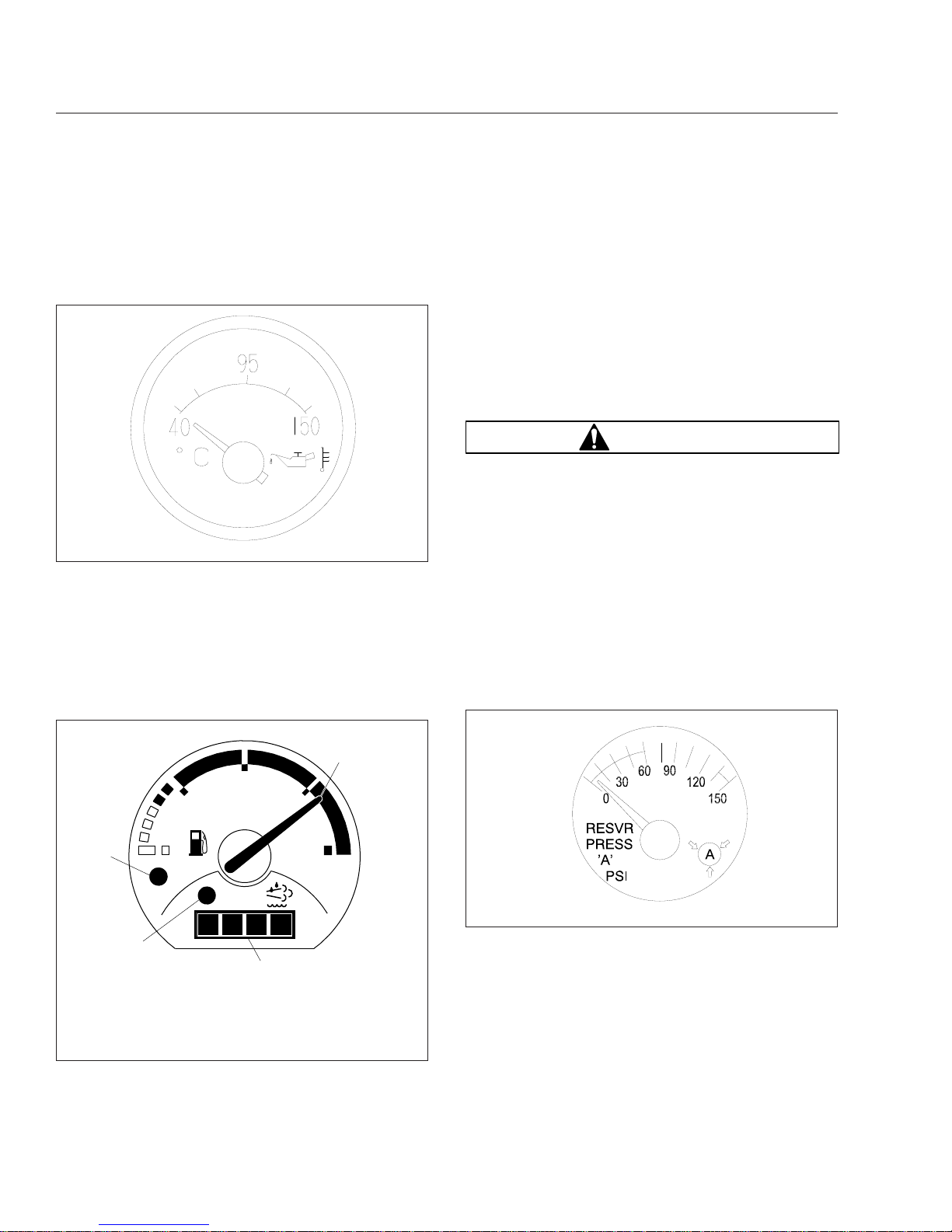
Coolant Temperature Gauge
NOTICE
A sudden increase in coolant temperature may
indicate engine or cooling system failure. Bring
the vehicle to a safe stop and investigate the
cause to prevent further damage. Do not operate
the engine until the cause has been determined
and corrected.
During normal engine operation, the coolant temperature gauge, as shown in
Fig. 4.7, should read
175 to 195°F (79 to 91°C). If the temperature remains below 160°F (71°C), inspect the cooling system to determine the cause.
If coolant temperature rises above the maximum
temperature listed in
Table 4.3, the CHECK engine
lamp will illuminate. If the condition does not improve, the STOP engine lamp will also illuminate and
an audible warning will sound. The engine will then
derate or shut down, depending on the type of engine protection system installed.
Maximum Coolant Temperature
Engine Make Temperature: °F (°C)
Caterpillar 230 (110)
Cummins 225 (107)
Detroit 215 (101)
Mercedes-Benz 222 (105)
Table 4.3, Maximum Coolant Temperature
Drive Axle Oil Temperature Gauges
NOTICE
A sudden increase in oil temperature that is not
caused by a load increase may indicate mechanical failure. Bring the vehicle to a safe stop and
investigate the cause to prevent further damage.
Do not operate the vehicle until the cause has
been determined and corrected.
During normal operation, drive axle oil temperature
gauges (see
Fig. 4.8) should read between 160 and
220°F (71 and 104°C).
04/08/2005 f090431
Fig. 4.6, Manual-Reset Air Restriction Indicator, Go/
No-Go
10/09/2001
f610565
WATER
100
150
200
250
F°
Fig. 4.7, Coolant Temperature Gauge
Instruments
4.9
Downloaded from www.Manualslib.com manuals search engine
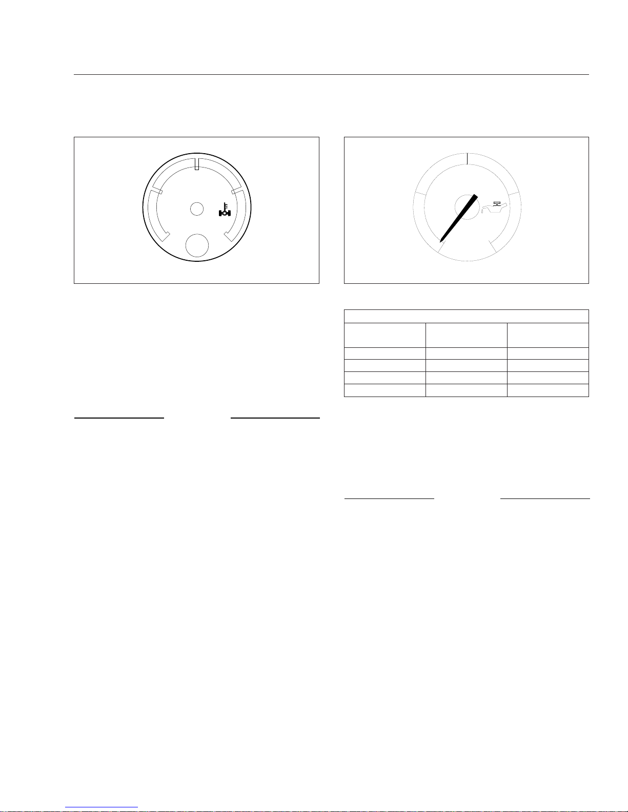
Under heavy loads, such as when climbing steep
grades, temperatures that exceed the normal oil temperature range for a short period are not unusual. If
the temperature returns to normal when the load decreases, there is no problem.
Engine Oil Pressure Gauge
NOTICE
A sudden decrease or absence of oil pressure
may indicate mechanical failure. Bring the vehicle
to a safe stop and investigate the cause to prevent further damage. Do not operate the engine
until the cause has been determined and corrected.
The engine oil pressure gauge, as shown in
Fig. 4.9,
displays the current engine oil pressure. If engine oil
pressure falls below the minimum levels shown in
Table 4.4, the CHECK engine lamp will illuminate. If
the condition does not improve, the STOP engine
lamp will also illuminate and an audible warning will
sound. The engine will then derate or shut down, depending on the type of engine protection system
installed.
Minimum Oil Pressure
*
Engine Model
At Idle Speed:
psi (kPa)
At Rated RPM:
psi (kPa)
Caterpillar 10–20 (69–138) 30–45 (207–310)
Cummins 15 (103) 35 (241)
Detroit 14 (97) 55 (350)
Mercedes-Benz 7 (50) 36 (250)
*
Oil pressures are given with the engine at operating temperature. With
the engine cold, oil pressure may be higher. Individual engines may vary
from the listed pressures; observe and record pressures when the engine
is new to create a guide for checking engine condition.
Table 4.4, Minimum Oil Pressure
Engine Oil Temperature Gauge
NOTICE
A sudden increase in oil temperature that is not
caused by a load increase may indicate mechanical failure. Bring the vehicle to a safe stop and
investigate the cause to prevent further damage.
Do not operate the engine until the cause has
been determined and corrected.
During normal operation, the optional engine oil temperature gauge (
Fig. 4.10) should read in the follow-
ing temperature ranges:
•
160 to 195°F (71 to 91°C) for Caterpillar engines
•
200 to 260°F (93 to 126°C) for Detroit and
Cummins engines
•
177 to 203°F (81 to 95°C) for Mercedes-Benz
engines
FWD
150 250
300100
°F
04/19/2013 f611205
Fig. 4.8, Forward-Rear Drive Axle Oil Temperature
Gauge
10/09/2001
0
100
50
PSI
OIL
f610528
Fig. 4.9, Engine Oil Pressure Gauge
Instruments
4.10
Downloaded from www.Manualslib.com manuals search engine
Under heavy loads, such as when climbing steep
grades, temperatures that exceed the normal oil temperature range for a short period are not unusual. If
the temperature returns to normal when the load decreases, there is no problem.
Fuel/Diesel Exhaust Fluid (DEF)
Gauge
For engines that are EPA10-compliant or newer, the
fuel and DEF levels are measured in a dual purpose
fuel/DEF level gauge. See
Fig. 4.11.
The diesel fuel level is indicated at the top of the
gauge, with a low-fuel warning lamp that illuminates
when the diesel fuel level registers 1/8th of capacity.
The DEF level is indicated in the lightbar on the
lower portion of the gauge. There is a low DEF level
warning lamp that illuminates amber when the DEF
level reaches 10% of capacity. See
Chapter 7 for
details of the DEF gauge functions.
Primary and Secondary Air Pressure
Gauges
WARNING
If air pressure falls below minimum pressure, the
braking ability of the vehicle will be limited. Slow
the vehicle down and bring it to a gradual stop.
Do not attempt to move the vehicle until air pressure has risen above the minimum level. Moving
a vehicle without adequate braking power could
cause an accident resulting in property damage,
personal injury, or death.
Air pressure gauges, as shown in
Fig. 4.12, register
the pressure in the primary and secondary air systems. The gauges are labeled for the A or B reservoir. Normal pressure with the engine running is 100
to 120 psi (689 to 827 kPa) in both systems.
A low-air-pressure warning light and audible alert,
connected to both the primary and secondary systems, activate when air pressure in either system
drops below approximately 70 psi (483 kPa).
When the engine is started, the warning light and
audible warning remain on until air pressure in both
systems exceeds minimum pressure.
10/10/2001
f610569
Fig. 4.10, Engine Oil Temperature Gauge
08/21/2009
1/2
ULTRA LOW SULFUR
DIESEL FUEL ONLY
EF
DEF
FE
f611045
1
2
3
4
1. Diesel Fuel Level Indicator
2. DEF Level Indicator
3. Low DEF Warning Lamp (amber below 10% DEF)
4. Low Fuel Warning Lamp (amber at 1/8 tank of fuel)
Fig. 4.11, Fuel/DEF Gauge, EPA10
05/14/2001
f610556
Fig. 4.12, Air Pressure Gauge (reservoir A shown)
Instruments
4.11
Downloaded from www.Manualslib.com manuals search engine
 Loading...