

Page 1

Foreword
Introduction
This manual provides information needed to operate
and understand the vehicle and its components.
More detailed information is contained in the
Warranty Information for North America
in the vehicle’s workshop and maintenance manuals.
Custom-built Freightliner vehicles are equipped with
various chassis and cab components. Not all of the
information contained in this manual applies to every
vehicle. For details about components in your vehicle, refer to the chassis specification pages included in all new vehicles and to the vehicle specification decal, located inside the vehicle.
For your reference, keep this manual in the vehicle
at all times.
IMPORTANT: Descriptions and specifications in this
manual were in effect at the time of printing. Freightliner Trucks reserves the right to discontinue models
and to change specifications or design at any time
without notice and without incurring obligation. Descriptions and specifications contained in this publication provide no warranty, expressed or implied,
and are subject to revisions and editions without notice.
Owner’s
booklet, and
Environmental Concerns and
Recommendations
Whenever you see instructions in this manual to discard materials, you should first attempt to reclaim
and recycle them. To preserve our environment, follow appropriate environmental rules and regulations
when disposing of materials.
Event Data Recorder
This vehicle is equipped with one or more devices
that record specific vehicle data. The type and
amount of data recorded varies depending on how
the vehicle is equipped (such as the brand of engine,
if an air bag is installed, or if the vehicle features a
collision avoidance system, etc.).
dination, or Fleetpack assistance. Our people are
knowledgeable, professional, and committed to following through to help you keep your truck moving.
Reporting Safety Defects
If you believe that your vehicle has a defect which
could cause a crash or could cause injury or
death, you should immediately inform the National
Highway Traffic Safety Administration (NHTSA) in
addition to notifying Daimler Trucks North America
LLC.
If the NHTSA receives similar complaints, it may
open an investigation, and if it finds that a safety
defect exists in a group of vehicles, it may order a
recall and remedy campaign. However, NHTSA
cannot become involved in individual problems
between you, your dealer, or Daimler Trucks North
America LLC.
To contact NHTSA, you may call the Vehicle
Safety Hotline toll-free at 1-888-327-4236 (TTY:
1-800-424-9153); go to www.safercar.gov;or
write to: Administrator, NHTSA, 1200 New Jersey
Avenue, SE, Washington, DC 20590. You can also
obtain other information about motor vehicle safety
from www.safercar.gov.
Canadian customers who wish to report a safetyrelated defect to Transport Canada, Defect Investigations and Recalls, may telephone the toll-free
hotline 1-800-333-0510, or contact Transport
Canada by mail at: Transport Canada, ASFAD,
Place de Ville Tower C, 330 Sparks Street,
Ottawa, Ontario, Canada K1A 0N5.
For additional road safety information, please visit
the Road Safety website at: www.tc.gc.ca/
roadsafety.
Customer Assistance Center
Having trouble finding service? Call the Customer
Assistance Center at 1-800-385-4357 or 1-800-FTLHELP. Call night or day, weekdays or weekends, for
dealer referral, vehicle information, breakdown coor-
STI-405-2 (10/11)
A24-01034-000
Printed in U.S.A.
Page 2

Foreword
© 2001–2011 Daimler Trucks North America LLC. All rights reserved. Daimler Trucks North America LLC is a Daimler
company.
No part of this publication, in whole or part, may be translated, reproduced, stored in a retrieval system, or transmitted
in any form by any means, electronic, mechanical, photocopying, recording, or otherwise, without the prior written permission of Daimler Trucks North America LLC. For additional information, please contact Daimler Trucks North
America LLC, Service Systems and Documentation, P.O. Box 3849, Portland OR 97208–3849 U.S.A. or refer to
www.Daimler-TrucksNorthAmerica.com and www.FreightlinerTrucks.com.
Page 3

Contents
Chapter Page
Introduction, Environmental Concerns and Recommendations,
Event Data Recorder, Customer Assistance Center, Reporting
Safety Defects ..................................................... Foreword
1 Vehicle Identification ...................................................... 1.1
2 Instruments and Controls Identification ....................................... 2.1
3 Vehicle Access .......................................................... 3.1
4 Heater and Air Conditioner ................................................. 4.1
5 Seats and Seat Belts ..................................................... 5.1
6 Steering and Brake Systems ............................................... 6.1
7 Engines and Clutches .................................................... 7.1
8 Transmissions ........................................................... 8.1
9 Rear Axles ............................................................. 9.1
10 Fifth Wheels and Trailer Couplings ......................................... 10.1
11 Pretrip and Post-Trip Inspections and Maintenance ............................ 11.1
12 Cab Appearance ........................................................ 12.1
13 In an Emergency ....................................................... 13.1
14 Headlight Aiming ........................................................ 14.1
Index .................................................................. I.1
Page 4

1
Vehicle Identification
Vehicle Specification Decal ......................................................... 1.1
Federal Motor Vehicle Safety Standard (FMVSS) Labels .................................. 1.1
Canadian Motor Vehicle Safety Standard (CMVSS) Labels ................................ 1.2
Tire and Rim Labels ............................................................... 1.2
EPA Emission Control ............................................................. 1.2
Page 5
Vehicle Identification
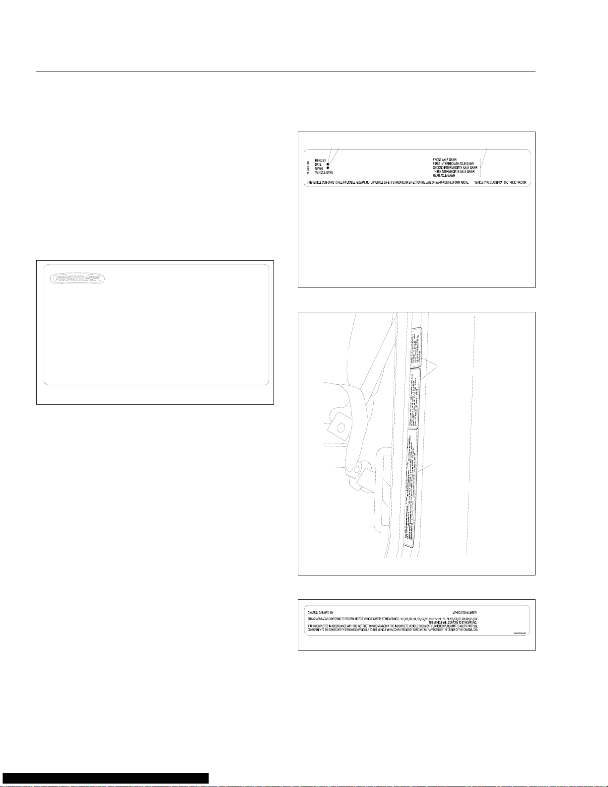
Vehicle Specification Decal
The vehicle specification decal lists the vehicle
model, identification number, and major component
models. It also recaps the major assemblies and installations shown on the chassis specification sheet.
One copy of the specification decal is attached to the
inside of the sliding storage/waste drawer; another
copy is inside the rear cover of the
Information for North America
of the decal is shown in Fig. 1.1.
COMPONENT INFORMATION
MANUFACTURED BY
MODEL
VEHICLE ID NO.
DATE OF MFR
ENGINE MODEL
TRANS MODEL MAIN
FRONT AXLE MODEL
REAR AXLE MODEL
IMRON PAINT−CAB
CAB COLOR A: WHITE (4775)
PAINT MFR
CAB COLOR B: BROWN (3295)
PAINT NO.
CAB COLOR C: BROWN (29607)
CAB COLOR D: DARK BROWN (7444)
11/21/96
Fig. 1.1, Vehicle Specification Decal (U.S.-built vehicle
shown)
Owner’s Warranty
booklet. An illustration
USE VEHICLE ID NO.
WHEN ORDERING PARTS
WHEELBASE
ENGINE NO.
TRANS NO.
FRT AXLE NO.
REAR AXLE NO.
REAR AXLE NO.
RATIO
FOR COMPLETE PAINT INFORMATION
SEE VEHICLE SPECIFICATION SHEET
PART NO. 24−00273−010
f080021
2
1
11/21/96
3
f080053
1. Date of Manufacture: by month and year
2. Gross Vehicle Weight Rating: developed by taking
the sum of all the vehicle’s gross axle ratings
3. Gross Axle Weight Ratings: developed by
considering each component in an axle system including suspension, axle, wheels, and tires - and
using the lowest component capacity as the value
for the system
Fig. 1.2, Certification Label, U.S.
1
NOTE: Labels shown in this chapter are examples only. Actual specifications may vary from
vehicle to vehicle.
Federal Motor Vehicle Safety
Standard (FMVSS) Labels
NOTE: Due to the variety of FMVSS certification
requirements, not all of the labels shown will
apply to your vehicle.
Tractors with or without fifth wheels purchased in the
U.S. are certified by means of a certification label
(Fig. 1.2) and the tire and rim labels. These labels
are attached to the left rear door post, as shown in
Fig. 1.3.
If purchased for service in the U.S., trucks built without a cargo body have a certification label (Fig. 1.4)
attached to the left rear door post. See Fig. 1.3.In
addition, after completion of the vehicle, a certification label similar to that shown in Fig. 1.2 must be
attached by the final-stage manufacturer. This label
will be located on the left rear door post and certifies
2
11/01/95
f601086
1. Tire and Rim Labels 2. Certification Label
Fig. 1.3, Labels Location
09/28/98
f080023
Fig. 1.4, Incomplete Vehicle Certification Label, U.S.
that the vehicle conforms to all applicable FMVSS
regulations in effect on the date of completion.
1.1
Page 6
Vehicle Identification
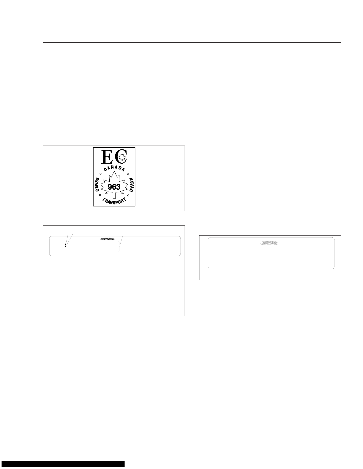
Canadian Motor Vehicle Safety
Standard (CMVSS) Labels
In Canada, tractors with fifth wheels are certified by
means of a "Statement of Compliance" label and the
Canadian National Safety Mark (Fig. 1.5), which are
attached to the left rear door post. In addition, tire
and rim labels (Fig. 1.6) are also attached to the left
rear door post.
f08002410/10/2006
Fig. 1.5, Canadian National Safety Mark
2
1
VEHICLE ID NO.
DATE OF MFR
GVWR
TIRES AND RIMS LISTED ARE NOT NECESSARILY THOSE INSTALLED ON THE VEHICLE.
10/31/95
FRONT AXLE
FIRST INTERMEDIATE AXLE
SECOND INTERMEDIATE AXLE
THIRD INTERMEDIATE AXLE
REAR AXLE
1. Date of Manufacture: by month and year
2. Gross Vehicle Weight Rating: developed by taking
the sum of all the vehicle’s gross axle ratings
3. Gross Axle Weight Ratings: developed by
considering each component in an axle system —
including suspension, axle, wheels, and tires — and
using the lowest component capacity as the value
for the system
Fig. 1.6, Tire and Rim Label
If purchased for service in Canada, trucks built without a cargo body and tractors built without a fifth
wheel are certified by a "Statement of Compliance"
label, similar to Fig. 1.2. This label must be attached
by the final-stage manufacturer after completion of
the vehicle. The label is located on the left rear door
post, and certifies that the vehicle conforms to all
applicable CMVSS regulations in effect on the date
of completion.
3
GAWR TIRES RIMS PSI COLD
24−00273−040
f080054
Tire and Rim Labels
Tire and rim labels certify suitable tire and rim combinations that can be installed on the vehicle, for the
given gross axle weight rating. Tires and rims installed on the vehicle at the time of manufacture may
have a higher load capacity than that certified by the
tire and rim label. If the tires and rims currently on
the vehicle have a lower load capacity than that
shown on the tire and rim label, then the tires and
rims determine the load limitations on each of the
axles.
See Fig. 1.6 for U.S. and Canadian tire and rim labels.
EPA Emission Control
Vehicle Noise Emission Control Label
A vehicle noise emission control label (Fig. 1.7)is
attached either to the left side of the dashboard or to
the top-right surface of the frontwall between the
dash and the windshield.
FREIGHTLINER CORPORATION
THIS VEHICLE CONFORMS TO U.S. EPA REGULATIONS FOR NOISE EMISSION
APPLICABLE TO MEDIUM AND HEAVY TRUCKS.
THE FOLLOWING ACTS OR THE CAUSING THEREOF BY ANY PERSON ARE PROHIBITED BY
THE NOISE CONTROL ACT OF 1972:
A. THE REMOVAL OR RENDERING INOPERATIVE, OTHER THAN FOR PURPOSES OF
MAINTENANCE, REPAIR, OR REPLACEMENT, OF ANY NOISE CONTROL DEVICE OR
ELEMENT OF DESIGN (LISTED IN THE OWNER’S MANUAL) INCORPORATED INTO THIS
VEHICLE IN COMPLIANCE WITH THE NOISE CONTROL ACT.
B. THE USE THIS VEHICLE AFTER SUCH DEVICE OR ELEMENT OF DESIGN HAS
BEEN REMOVED OR RENDERED INOPERATIVE.
10/06/98
VEHICLE NOISE EMISSION CONTROL INFORMATION
DATE OF MANUFACTURE
Fig. 1.7, Vehicle Noise Emission Control Label
IMPORTANT: Certain Freightliner incomplete
vehicles may be produced with incomplete noise
control hardware. Such vehicles will not have a
vehicle noise emission control information label.
For such vehicles, it is the final-stage manufacturer’s responsibility to complete the vehicle in
conformity to U.S. EPA regulations (40 CFR Part
205) and label it for compliance.
EPA07 Exhaust Emissions
To meet January 2007 emissions regulations, vehicles with engines manufactured after January 1,
2007, are equipped with an emission aftertreatment
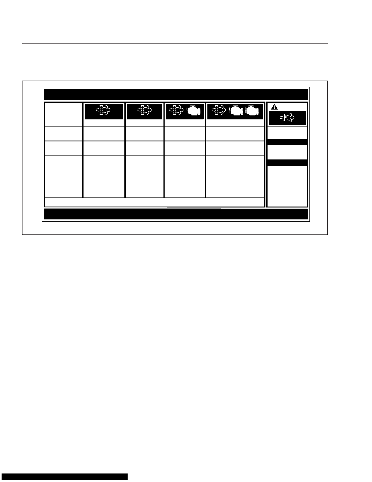
device. There is a warning label on the driver’s sunvisor, explaining important new warning indicators in
the driver’s message display, that pertain to the aftertreatment system. See Fig. 1.8.
01/96
24−00273−020
f080026
1.2
Page 7
Vehicle Identification
EXHAUST AFTERTREATMENT SYSTEM INFORMATION
INDICATOR
LAMP(S)
Indicator Lamp
Message(s)
Diesel Particulate
Filter Condition
Required Action
For a driver performed Parked Regeneration, vehicle must be equipped with a dash mounted Regeneration Switch.
(Solid)
Level 1 Level 3Level 2 Level 4
Filter Regeneration
Recommended
Filter is reaching
capacity
. .
Bring vehicle to
highway speeds to
allow for an Automatic
Regeneration or
perform a Parked
Regeneration.
(Flashing) (Flashing)
Filter Regeneration
Necessary
Filter is now
reaching maximum
capacity
Switch.
.
To avoid engine
derate bring vehicle
to highway speeds
to allow for an
Automatic
Regeneration or
perform a Parked
Regeneration as
soon as possible.
CHECK CHECK
Parked Regeneration
Required − Engine
Derate
Filter has reached
maximum capacity
Vehicle must be
parked and a Parked
Regeneration must
be performed −
engine will begin
derate.
(Flashing)
Parked Regeneration Required −
Engine Shut Down
Filter has exceeded
maximum capacity
.
Vehicle must be parked and a
Parked Regeneration or Service
Regeneration must be performed.
Check engine operator’s manual
for details −engine will shut down.
STOP
W
ARNING
HEST (High Exhaust
System Temperature)
Flashing
A regeneration is in
progress.
Solid
Exhaust Components
and exhaust gas are
at high temperature.
When stationary, keep
away from people and
flammable materials
or vapors.
See Engine Operator’s Manual for complete Regeneration Instructions.
06/29/2009
Fig. 1.8, Sunvisor Warning Label
It is a violation of federal law to alter exhaust plumbing or aftertreatment in any way that would bring the
engine out of compliance with certification requirements. (Ref: 42 U.S.C. S7522(a) (3).) It is the owner’s responsibility to maintain the vehicle so that it
conforms to EPA regulations.
24−01583−000B
f080147
1.3
Page 8

2
Instruments and Controls
Identification
Instrument and Control Panel ....................................................... 2.1
Instrumentation Control Unit 4 (ICU4 and ICU4-2) ....................................... 2.3
Instrumentation Control Unit 3 (ICU3 and ICU3 ’07) ...................................... 2.7
Instrumentation Control Unit 2L (ICU2L) .............................................. 2.11
Instruments ..................................................................... 2.12
Controls ........................................................................ 2.17
Collision Warning System (CWS), Eaton VORAD EVT–300, Optional ...................... 2.33
™
Lane Guidance
Roll Stability Control .............................................................. 2.39
System, Optional .................................................. 2.38
Page 9
Instruments and Controls Identification
Instrument and Control Panel
Engine Protection—Warning and
Shutdown Process
WARNING
When the red STOP engine or engine protection
light illuminates, most engines are programmed
to shut down automatically within 30 seconds.
The driver must immediately move the vehicle to
a safe location at the side of the road to prevent
causing a hazardous situation that could cause
bodily injury, property damage, or severe damage
to the engine.
The driver should be familiar with the vehicle warning
system, in order to bring the vehicle to a safe stop if
the engine malfunctions. If the driver doesn’t understand how the warning system works, an engine
shutdown could occur, causing a safety hazard.
If the engine coolant temperature, the coolant level,
the engine oil pressure, or the diesel particulate filter
for the exhaust aftertreatment system, (on some engines, the engine oil temperature, or the intake air
temperature also,) reach preset levels, the engine
will begin a warning and shutdown process. See the
engine manufacturer’s engine operation manual for
your vehicle, for specific details. See the "EPA07 Aftertreatment System" information in Chapter 7 in this
manual, for a description of the warning and shutdown modes associated with the exhaust aftertreatment system.
There are four customer-programmable levels for
electronic engine protection: OFF, WARNING, DERATE, and SHUTDOWN (factory default).
In the engine monitoring OFF mode, the individual
sensor indicator lights will illuminate if a problem exists, but no shutdown action will be started, and the
event will not be recorded.
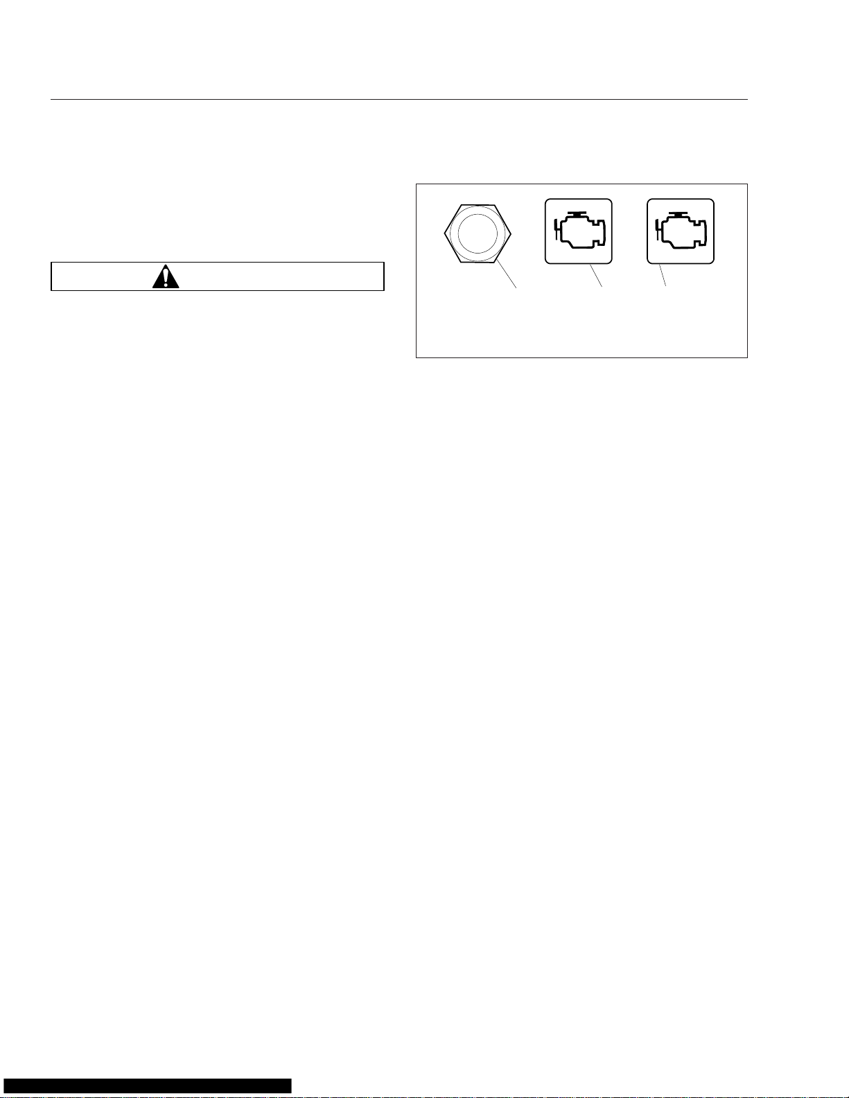
The WARNING mode warns the driver, and the engine electronics will log the event for diagnostic purposes. The amber Check Engine lamp will flash, and
the buzzer will sound. The amber Check Engine
lamp will go out if the problem stops. See Fig. 2.1
CHECK
03/20/2008 f611000
1. Stop Engine Override Switch
2. Amber Check Engine Warning Lamp
3. Red Stop Engine Lamp
The DERATE and SHUTDOWN modes will reduce
the power to the engine, then shutdown the engine,
to avoid engine damage. The red Stop Engine light,
(ENG PROT or SHUT DOWN for older vehicles), will
illuminate when the problem is serious enough to
reduce the power or speed. The engine power will
ramp down, then shut down, if the problem continues.
The driver has about 30 seconds, after the red Stop
Engine light illuminates, to move the vehicle safely
off the road. If the vehicle cannot be moved to a safe
location within that time, the engine can be restarted
by turning the ignition switch to the OFF position for
at least 5 seconds, then back ON, or by pushing the
stop-engine-overide button if the vehicle is equipped
with one. This action can be repeated until the vehicle is safely off the road. Do not operate the vehicle until the problem has been corrected.
123
Fig. 2.1, Engine Lamps
STOP
Warning and Indicator Lights
The dash lightbars have warning and indicator lights
that may be lettering or icons. Up until December 31,
2006, the warning and indicator lights are a mixture
of ISO icons, and lettering. Since January 2007, ISO
icons are used for all standard warning and indicator
lights on the dash lightbar. See the following table for
a full description of the icons used.
2.1
Page 10
CHECK
STOP
Instruments and Controls Identification
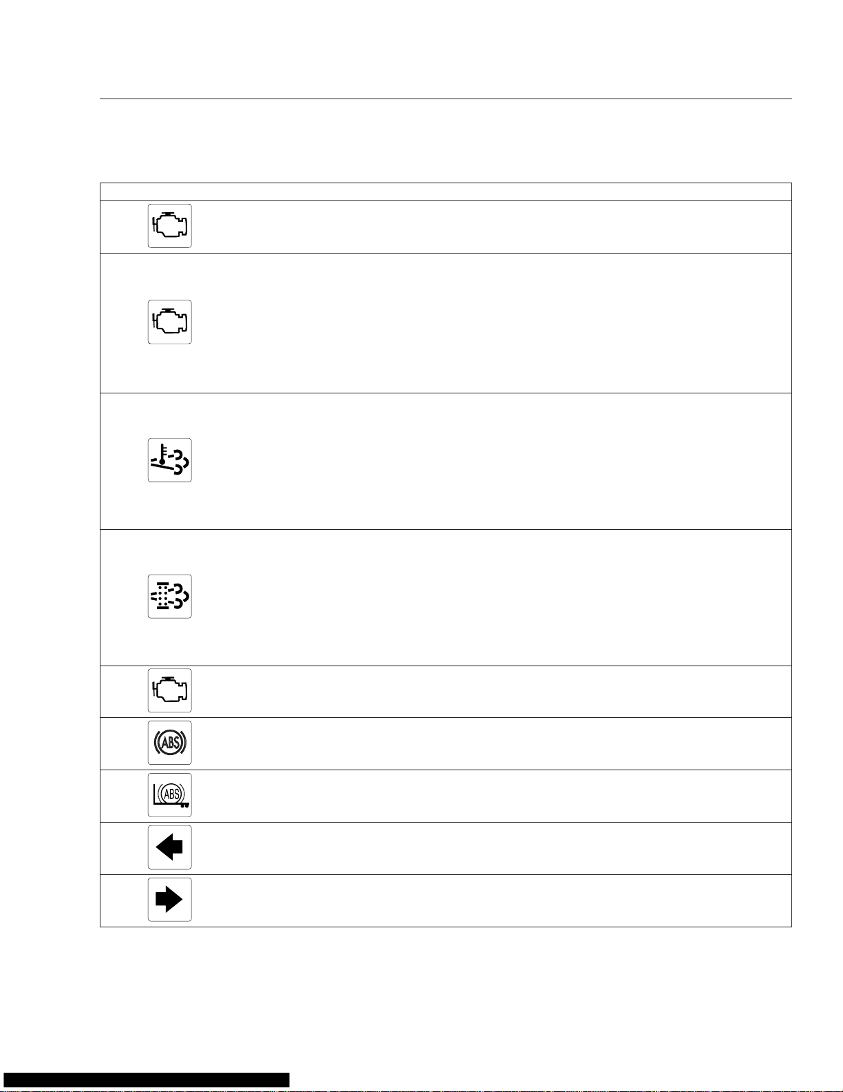
Warning and Indicator Lights
Check Engine Lamp (amber)
Stop Engine or Engine Protect
Lamp (red)
High Exhaust System Temperature
(HEST) Lamp (amber)
Diesel Particulate Filter (DPF)
Status Lamp (amber)
Malfunction Indicator Lamp (MIL)
(amber)
Indicates an undesirable engine condition is detected or
recorded. If the condition gets worse, the stop engine or
engine protection light will illuminate.
Indicates a serious fault that requires the engine shut down
immediately. The engine ECU will reduce the maximum
engine torque and speed, and, if the condition does not
improve, will shut down the engine within 30 seconds of the
light illuminating. The driver must safely bring the vehicle to
a stop on the side of the road and shut down the engine as
soon as the red light is seen. If the engine shuts down while
the vehicle is in a hazardous location, the engine can be
restarted after turning the key to the OFF position for a few
seconds.
Slow (10-second) flash, indicates a regeneration is in
progress, and the driver is not controlling the engine idle
speed.
Steadily illuminated indicates a regeneration is in progress,
with high exhaust temperatures at the outlet of the tail pipe,
if the speed is below 5 mph (8 km/h). It does not signify the
need for service; it only alerts the vehicle operator of high
exhaust temperatures. See the engine operation manual for
details.
Steadily illuminated indicates a regeneration is required.
Change to a more challenging duty cycle, such as highway
driving, to raise exhaust temperatures for at least 20
minutes, or perform a parked regeneration. See the engine
operation manual for details.
Blinking indicates that a parked regeneration is required
immediately.An engine derate and shutdown will occur. See
the instructions in the manufacturer’s
manual
Indicates an engine emissions-related fault, including, but not
limited to the aftertreatment system. See the engine
operation manual for details.
for instructions to perform a stationary regeneration.
engine operation
Tractor ABS Lamp (amber)
Trailer ABS Lamp (amber) Indicates a fault is detected with the trailer ABS.
Left-Turn Signal (green)
Right-Turn Signal (green)
Indicates a problem with the ABS is detected. Repair the
tractor ABS immediately to ensure full antilock braking
capability.
Flashes on and off whenever the outside turn signal lights
are flashing.
Flashes on and off whenever the outside turn signal lights
are flashing.
2.2
Page 11
Instruments and Controls Identification
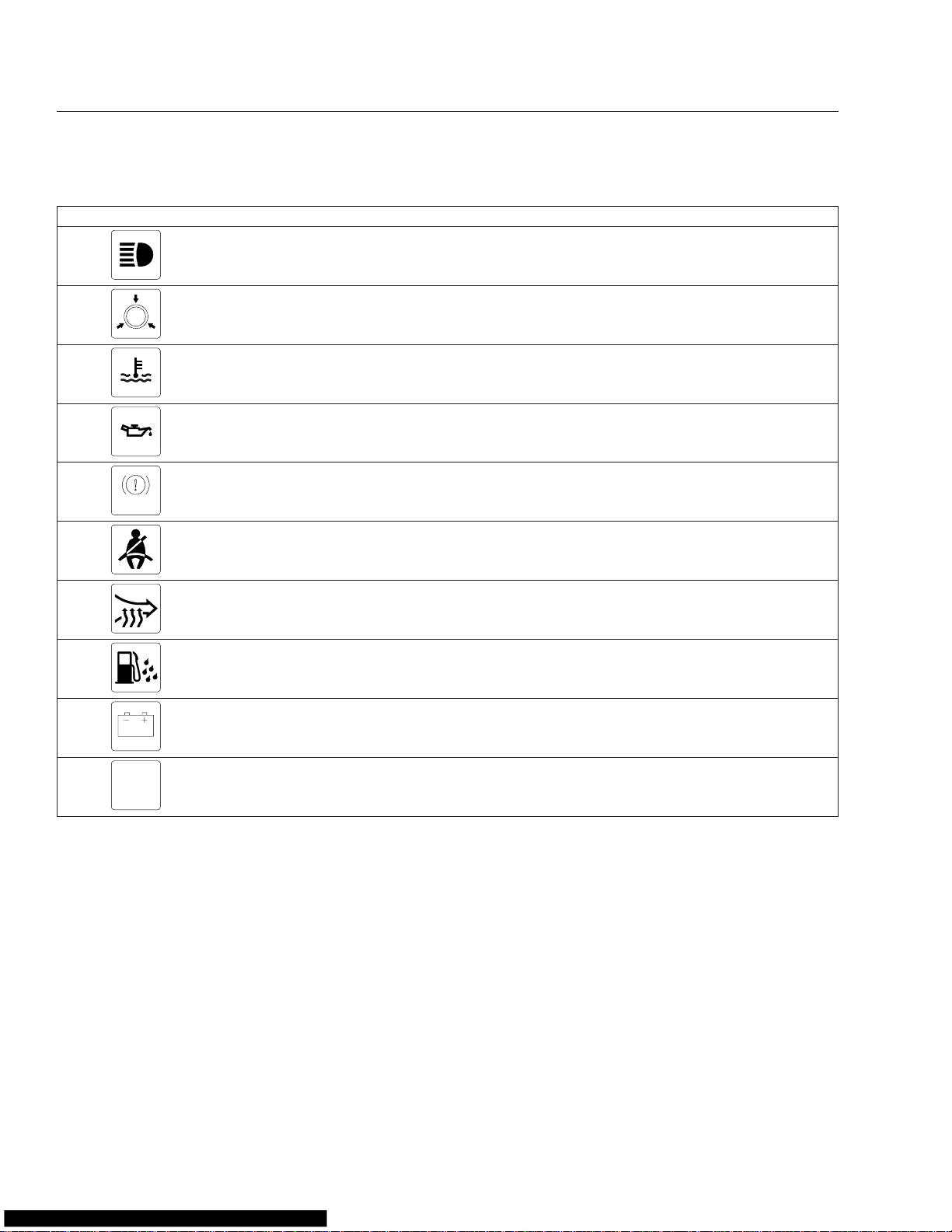
Warning and Indicator Lights
High-Beam Indicator (blue) Indicates the headlights are on high beam.
BRAKE
Low Air Pressure Warning Lamp
(red)
High Coolant Temperature Warning
Lamp (red)
Low Engine Oil Pressure Warning
Lamp (red)
Parking/Emergency Brake Lamp
(BRAKE!) (red)
Fasten Seat Belt Warning Lamp
(red)
Intake Heater Warning Lamp
(amber)
Water in Fuel Warning Lamp
(amber)
Low Battery Voltage Warning Lamp
(red)
Activates with a buzzer when air pressure in the primary or
secondary air reservoir falls below 64 to 76 psi (440 to 525
kPa).
Activates with a buzzer when the coolant temperature goes
above a maximum level specified by the engine
manufacturer (see the engine manual).
Activates with a buzzer when engine oil pressure goes below
a minimum level specified by the engine manufacturer (see
the engine manual).
Indicates the parking brake is engaged, or hydraulic brake
fluid pressure is low. A buzzer activates when the vehicle is
moving over 2 mph (3 km/h) with the parking brake set.
Illuminates for 15 seconds when the ignition key is turned to
the ON position.
Indicates the intake air heater is active.
Indicates that the fuel could contain water.
Indicates battery voltage is 11.9 volts or less.
NO
CHARGE
No Charge Warning Lamp (amber) Indicates an alternator charge output failure.
Instrumentation Control Unit 4
(ICU4 and ICU4-2)
The ICU4 and ICU4-2 instrument clusters are
individual-gauge clusters, with intelligent lightbars
(ILB) and integrated warning and indicator lights. See
Fig. 2.2 for a typical layout of the gauges. The ICU4
is on vehicles with engines that were manufactured
up until December 31, 2006, and the ICU4-2 is on
vehicles with engines that were manufactured January 1, 2007 or later, that are EPA07 compliant. They
can be differentiated by the ISO icons on the ICU4-2.
See Fig. 2.3 and Fig. 2.4. Also, on the ICU4, the
message display shows voltmeter readings.
2.3
Standard gauges are:
•
speedometer
•
engine coolant temperature
•
engine oil pressure
•
battery voltmeter
•
fuel level
Gauges with a warning light on the gauge are listed
below, with an indication of how the warning light is
activated:
•
engine coolant temperature (high)
•
engine oil pressure (low)
Page 12
Instruments and Controls Identification
40
PSI
0
100
OIL
200
150
F
100
250
WATER
12
200
F
100
300
OIL
3
90
F
10
30
150
PYRO
12
8
16
VOLTS
4
40
PSI
0
80
TURBO
56
10060
PSI
P
7
8
0 160
AIR
11 12
15
25
5
MPH
45
55
35
70
65
90
50
110
30
10
75
130
85
km/h
13
1/2
EF
FUEL
190
270
F
110
350
TRANS
15
RPM
X 100
20
25
30
10
10
5
0
9
15
14
16
PSI
0 160
200
F
100
AXLE
200
F
100
AXLE
10060
S
AIR
300
300
04/01/2004 f610706
1. Engine Oil Pressure Gauge
2. Engine Coolant Temperature
Gauge
3. Engine Oil Temperature Gauge
4. Battery Voltage Gauge
5. Pyrometer
6. Turbo Boost Air Pressure Gauge
7. Dash Message Center
8. Mode/Reset Switch
9. Tachometer
10. Speedometer
11. Primary Air Pressure Gauge
12. Secondary Air Pressure Gauge
13. Fuel Level Gauge
14. Axle Temperature Gauge
15. Transmission Oil Temperature
Gauge
16. Axle Temperature Gauge
Fig. 2.2, ICU4/ICU4-2 Instrument Cluster (ICU4 shown)
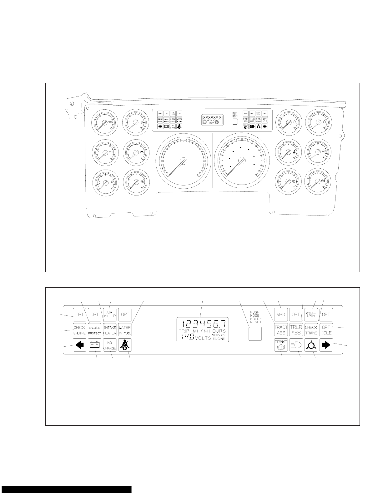
4
56
3
2
1
2122
06/22/2004
1. Left-Turn Signal
2. Check Engine Indicator
3. Optional Indicator
4. Engine Protection Indicator
5. Intake Heater Indicator
6. Air Filter Indicator
7. Water in Fuel Indicator
8. Message Display Screen
78
910
20
9. Mode/Reset Switch
10. Tractor ABS Indicator
11. Message Indicator
17. Low Air System Pressure Warning
18. High-Beam Indicator
19. Parking/Emergency Brake
12. Trailer ABS Indicator
13. Wheel Spin Indicator
14. Check Transmission Indicator
15. Optimized Idle Indicator
20. Fasten Seat Belt Warning
21. No Charge Indicator (alternator)
22. Low Vehicle Battery Voltage
16. Right-Turn Signal
Fig. 2.3, ICU4 Dash Message Center (typical), Pre-2007
11
19
Warning
12 13
14
15
16
1718
f610707
2.4
Page 13
Instruments and Controls Identification
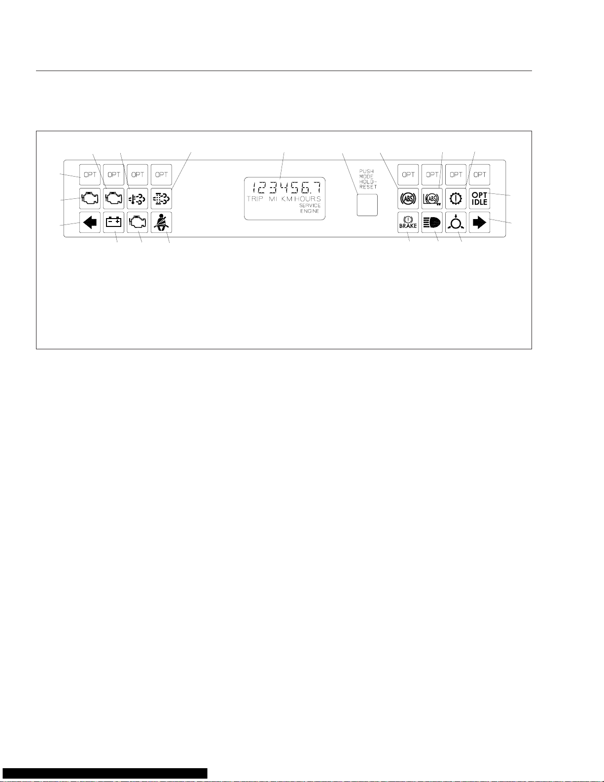
4
5
3
2
1
09/05/2006
1. Left-Turn Signal
2. Check Engine Indicator
3. Optional Indicator
4. Stop Engine Warning
5. High Exhaust System
6. Diesel Particulate Filter Status
•
•
CHECK STOP
1819
Temperature (HEST) Warning
Lamp (DPF)
Fig. 2.4, ICU4-2 Dash Message Center (typical), EPA07 Compliant
fuel level (low)
transmission oil temperature (high)
67
17
7. Message Display Screen
8. Mode/Reset Switch
9. Tractor ABS Indicator
10. Trailer ABS Indicator
11. Check Transmission Indicator
12. Optimized Idle Indicator
13. Right-Turn Signal
Other available gauges include:
•
tachometer
•
engine oil temperature
•
transmission oil temperature
•
axle temperature; forward-rear, and rear-rear
•
ammeter
•
air pressure; primary, secondary, application,
and suspension
•
pyrometer
•
turbo boost
Buzzer and Chime
A buzzer sounds for three seconds during the selftest at start-up, and when the following conditions
exist:
•
low air pressure
•
low oil pressure
•
high coolant temperature
89
16
14. Low Air System Pressure Warning
15. High-Beam Indicator
16. Parking/Emergency Brake
Warning
17. Fasten Seat Belt Warning
18. Malfunction Indicator Light (MIL)
19. Low Vehicle Battery Voltage
•
the parking brake is applied and the vehicle is
10
11
12
13
1415
f610817
moving at a speed of at least 2 mph (3 km/h)
A chime sounds when the parking brake is off and
the door is open, or when the headlights are on and
the door is open.
Ignition Sequence
When the ignition key is turned on, the ICU4/ICU4-2
begins a self-test. During this process, all gauges
controlled by the cluster sweep to full scale and return, the buzzer sounds for three seconds, the fasten
seat belt warning light illuminates for 15 seconds,
and the battery voltage, low air pressure, and parking
brake warning lights illuminate then turn off. Then the
software revision level of the ICU4/ICU4-2 is displayed, followed by active faults, if any, then the
odometer display.
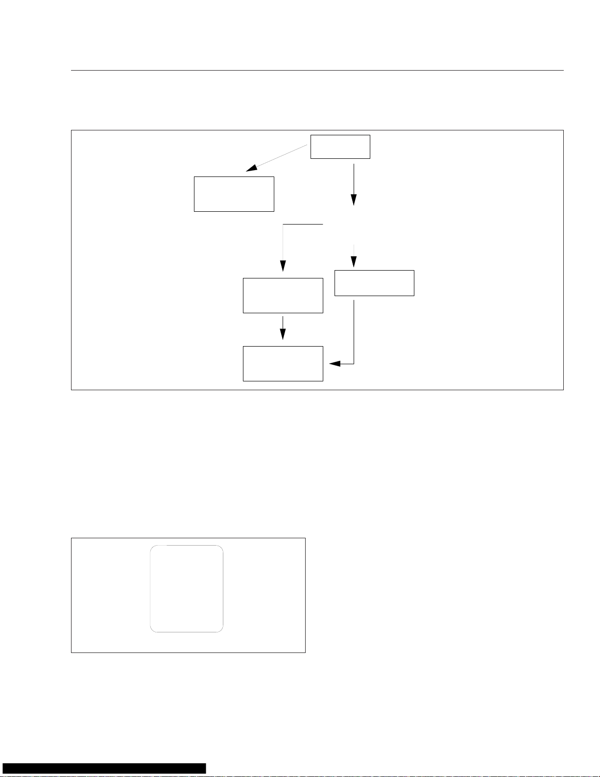
Mode/Reset Switch Functions
The mode/reset switch controls the display of the
odometer, trip miles and hours, engine miles and
hours, service cycle screens, fault code screens, and
oil level screens (on some Mercedes-Benz engines;
if equipped and enabled).
Push the switch to scroll through mode selections,
and hold the switch to reset trip miles or hours while
they are displayed. See Fig. 2.5. With the parking
2.5
Page 14
Instruments and Controls Identification
With park brake off
06/01/2004
Default Odometer
Display Screen
Push
Hold
Push
Hold
Push
With park brake on
If "SERVICE" is displayed Service Cycle screens are enabled and either "MI" or "HOURS" is also displayed.
On some vehicles "OIL LVL" appears in the top row of the display, if equipped and enabled.
Fig. 2.5, ICU4/ICU4-2 Mode/Reset Switch Basic Functions
To Reset Trip Miles
To Reset Trip Hours
Push
Push
Push
Hold
Go to the Diagnostic
Hold
Hold
For setup screens.
and Engine Display
Screens figure.
Go to the Diagnostic
and Engine Display
Screens figure.
f040693
brake released, only the odometer, trip miles, and trip
hours can be accessed. Park the vehicle and set the
parking brake to access additional screen functions.
See Fig. 2.6.
Trip Miles, Trip Hours
When the odometer is displayed, push the mode/
reset switch once to display trip distance. Push it
again to display trip hours. Both numbers are calculated from the last time the value was reset. Hold the
switch when each number is displayed to reset trip
miles or hours to zero.
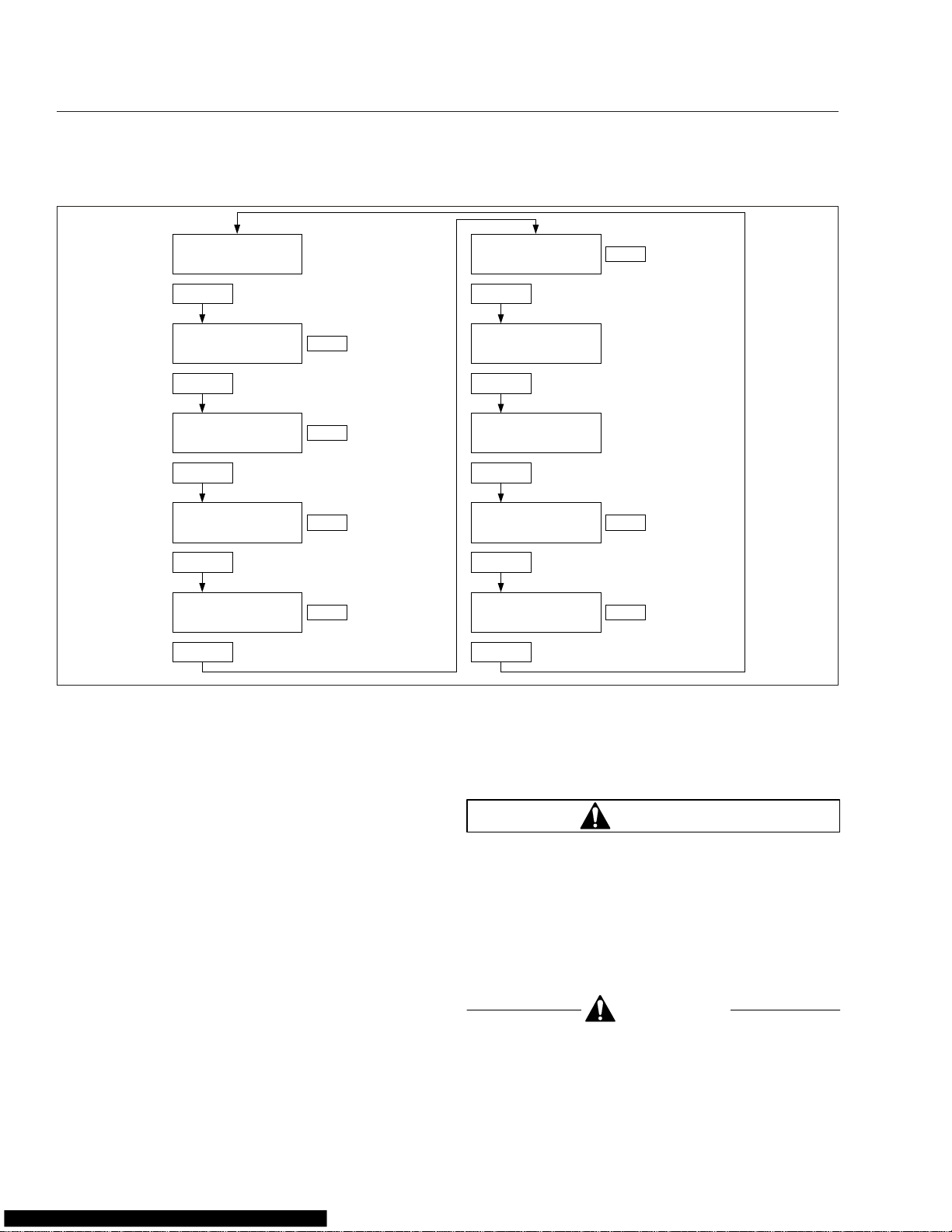
Diagnostic Screens
During vehicle start-up, with the parking brake on,
the ICU4 or ICU4-2 display any active fault codes for
three seconds each until the parking brake is released. With active fault codes on display, push the
mode/reset switch once to display the initial diagnostic screen (DIAG) and the total number of active
faults. If service cycle screens are enabled, and ser-
vice distance or time has been exceeded, the text
SERVICE will be displayed with the other fault messages. This will inform the vehicle operator that the
service interval has been exceeded and vehicle service is required.
Specific fault code information can be displayed only
with the vehicle parked and the parking brake set. If
the odometer screen is displayed, push the mode/
reset switch until the DIAG screen is displayed, then
hold the switch to enter the fault code screen sequence. Once the initial fault code is displayed, push
the switch to cycle through additional diagnostic
codes relating to the first fault. Hold the switch to display additional faults or return to the DIAG screen. If
service cycle screens are enabled, service interval
information is displayed before fault code information
is displayed.
If the word SERVICE appears on the DIAG message
display screen, service cycle screens are enabled.
Hold the mode/reset switch at the DIAG screen to
2.6
Page 15
Instruments and Controls Identification
If Service Cycle screens not enabled
Push
Or
Hold
Push
Hold
Service Cycle Screens (if enabled):
Holding the button displays Service
Miles or Service Hours, remaining or
exceeded, to service target. If
numbers flash, the service target is
exceeded and service is overdue.
Also, the "SERVICE" screen will be
displayed as an active Fault Code
when service miles or hours are ex−
ceeded.
Then
Hold
Push
Push
Hold
For additional faults,
if any, or return to
DIAG screen.
To display total
engine miles.
Hold
To display tolal
engine hours.
Hold
If "SERVICE" is displayed Service Cycle screens are enabled and either "MI" or "HOURS" is also displayed.
04/28/2004 f040695
On some vehicles "OIL LVL" appears in the top row of the display, if equipped and enabled.
To display OIL LVL
screens (if equipped
and enabled).
Hold
To display specific
OIL LVL amount
over or under full.
Push
Push
Fig. 2.6, ICU4/ICU4-2 Mode/Reset Switch Diagnostic and Engine Display Screens
display miles or hours remaining until the next scheduled service. If MI appears on the DIAG screen, service miles are enabled; if HOURS appears on the
screen, service hours are enabled. Either service
miles or hours can be enabled, but not both. If service miles or hours has been exceeded, the number
flashes to indicate service is overdue.
Engine Screens
Push the mode/reset switch once following the DIAG
screen and the word ENGINE is displayed in the
lower right corner of the digital display. Hold the
switch to display total engine miles. Hold it again to
display total engine hours. If OIL LVL is displayed
earlier with ENGINE (only on vehicles with
Mercedes-Benz engines; if equipped and enabled)
hold the switch again to access oil level screens.
Instrumentation Control Unit 3
(ICU3 and ICU3 ’07)
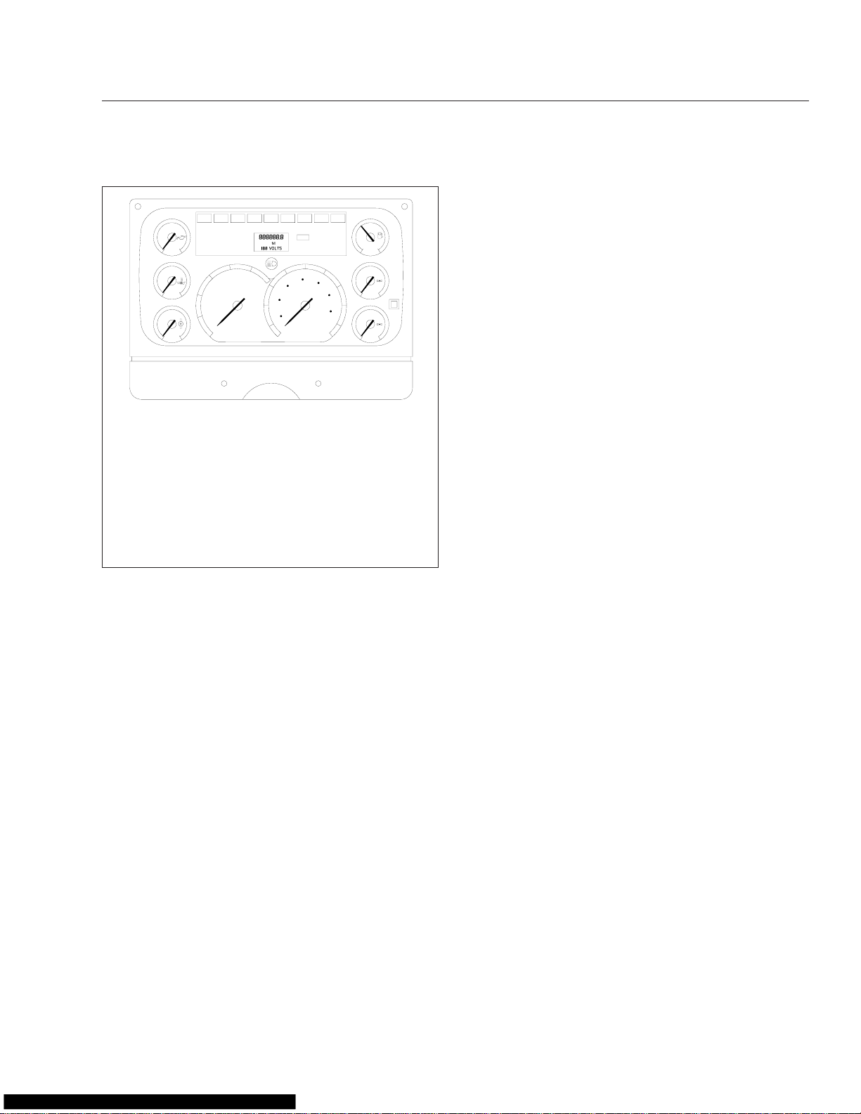
Figure 2.7 shows the instrument panel for Columbia
vehicles equipped with the ICU3 and ICU3 ’07. The
ICU3 is on vehicles with engines that were manufactured up until December 31, 2006, and the ICU3 ’07
is on vehicles with engines that were manufactured
January 1, 2007 or later. They can be differentiated
by the ISO icons used on the ICU3 ’07.
The ICU3 and ICU3 ’07 electronic dashboards can
accept information from the various sensors installed
on the vehicle and feed it to electronic gauges. Only
air gauges operate mechanically.
There can be up to eight gauges on the driver’s instrument panel (six electronic and two mechanical).
The ICU3 or ICU3 ’07 can not drive gauges located
on the auxiliary instrument panel.
The dash message center is the heart of the ICU3
and ICU3 ’07. It has a set of warning and indicator
2.7
Page 16
Instruments and Controls Identification
65
75
85
1/2
5
E
F
FUEL
6
50
100
PSI
150
0
AIR
50
100
PSI
8
150
0
AIR
f610205b06/02/99
™
System is
7
50
3
PSI
0
100
OIL
200
150
2
F°
100
250
WATER
225
1
F°
100
350
TRANS
4
20
25
15
10
5
0
RPM
X100
30
10
45
55
35
70
90
50
25
15
5
110
30
130
10
km/h
9
MPH
1. Transmission Temperature Gauge
2. Water Temperature Gauge
3. Engine Oil Pressure Gauge
4. Dash Message Center
5. Fuel Gauge
6. Primary Air Pressure Gauge
7. Optional Mode/Reset Push Button
8. Secondary Air Pressure Gauge
9. Speedometer
10. Tachometer
Fig. 2.7, ICU3/ICU3 ’07 Gauge Layout (ICU3 shown)
lights, and a driver display screen. The driver display
screen is a one-line by seven-character liquid crystal
display (LCD) that normally shows odometer readings.
There are four rows of lights in the dash message
center. Lights installed in the top row are optional
and their positions may vary. The lights in the bottom
three rows are installed in fixed positions on all vehicles. Most are standard, but a few are optional.
See Fig. 2.8 and Fig. 2.9.
NOTE: The functions of the ABS/ATC warning
lights are explained under "Meritor WABCO Antilock Braking System (ABS)", later in this chapter.
NOTE: The amber LANE SRCHNG warning
light for the optional Lane Guidance
explained later in this chapter.
Buzzer
A buzzer sounds for three seconds during the selftest at start-up, and when the following conditions
exist:
•
low air pressure
•
low oil pressure
•
high coolant temperature
•
the parking brake is applied and the vehicle is
moving at a speed of at least 2 mph (3 km/h)
ICU3/ICU3 ’07 Ignition Sequence
If the headlights are turned on, the screen displays
the odometer and waits for the ignition to be turned
on.
When the ignition is turned on, all the electronic
gauges complete a full sweep of their dials, the
warning and indicator lights light up, and the buzzer
sounds for three seconds.
NOTE: The air gauges do not sweep.
The following lights illuminate during the ignition sequence:
•
Fasten Seat Belt Warning
•
Low Battery Voltage Warning
•
High Coolant Temperature Warning
•
Low Engine Oil Pressure Warning
•
Low Air Pressure Warning
•
Parking Brake On Indicator
•
All engine warning lights, including engine protection, check engine, and (Cummins only)
stop engine
•
All ABS warning lights, including wheel spin,
tractor ABS, and (if installed) trailer ABS
See Fig. 2.10 for the ICU3/ICU3 ’07 ignition
sequence.
NOTE: Although the engine and ABS warning
lights illuminate during the ignition sequence,
they are not controlled by the ICU, but by their
own system ECU (electronic control unit).
When the ignition switch has been turned on, the
ICU3 performs a self-test, looking for active faults.
During the first half of the self-test, all segments of
the display illuminate as follows: 888888.8. The ICU3
voltmeter display also illuminates, but with the value
18.8. During the second half of the self-test, the software revision level is displayed.
2.8
Page 17
Instruments and Controls Identification
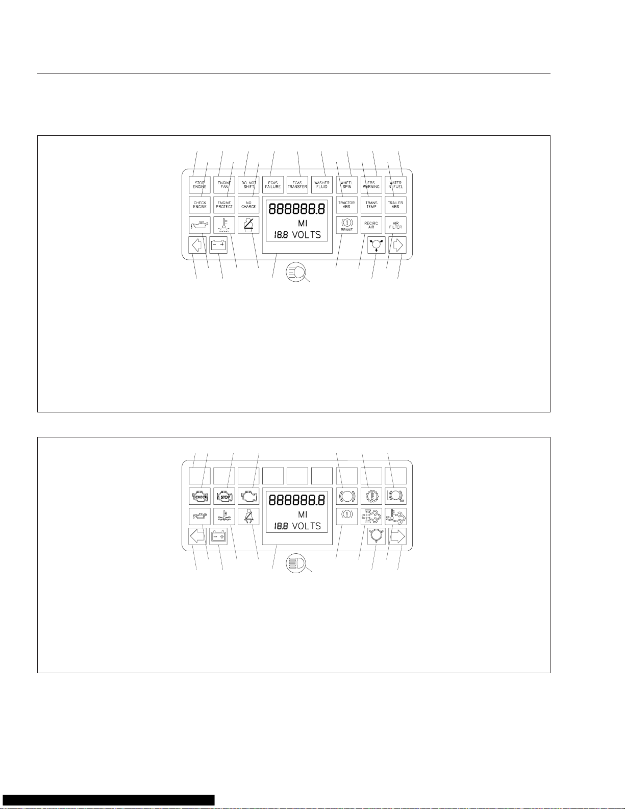
11/10/2006
1. Stop Engine Warning
2. Engine Fan On Indicator (optional)
3. Do Not Shift Indicator (optional)
4. ECAS Failure Warning (optional)
5. ECAS Transfer Indicator (optional)
6. Low Washer Fluid Indicator
(optional)
7. Wheel Spin Indicator (optional)
8. EBS Warning (optional)
9. Water In Fuel Indicator (optional)
10. Check Engine Indicator
3
4
12
18
24
22
2
1
10
11
16
17
23
11. Engine Protection Warning
(optional)
5
25
6
13 14
19
78
15
21
20
26 27
19. Parking Brake On Warning
20. Recirculated Air Indicator
12. No Charge Indicator (optional)
13. Tractor ABS Warning
14. Transmission Temperature
Warning (optional)
15. Trailer ABS Warning
16. Low Oil Pressure Warning
17. High Coolant Temperature
Warning
21. Air Restriction Indicator (optional)
22. Left-Turn Signal
23. Low Battery Voltage Warning
24. Dash Driver Display Screen
25. High Beams On Indicator
26. Low Air Pressure Warning
27. Right-Turn Signal
18. Fasten Seat Belt Warning
Fig. 2.8, ICU3 Dash Message Center, Pre-2007
9
f610231a
(optional)
4
3
10
9
Status Lamp
Temperature (HEST) Warning
08/31/2006
1. Optional Indicator
2. Check Engine Indicator
3. Stop Engine Indicator
4. Malfunction Indicator Light (MIL)
5. Tractor ABS Indicator
6. Transmission Temperature
Indicator
7. Trailer ABS Indicator
2
1
OPT OPT OPT OPT OPT OPT OPT OPT OPT
8
14
15
8. Low Oil Pressure Warning
9. High Coolant Temperature
10. Fasten Seat Belt Warning
11. Parking Brake On Warning
12. Diesel Particulate Filter (DPF)
13. High Exhaust System
Fig. 2.9, ICU3 ’07 Dash Message Center, EPA07 Compliant
If there are no active faults, the ICU3/ICU3 ’07 displays the odometer. However, if the ICU3/ICU3 ’07
16
56
11
17
ABS
BRAKE
12
7
ABS
13
18 19
f610836
14. Left-Turn Signal
15. Low Battery Voltage Warning
16. Driver Display Screen
17. High Beams On Indicator
18. Low Air Pressure Warning
19. Right-Turn Signal
has received active fault codes from other devices, it
displays them one after the other until the parking
2.9
Page 18
Instruments and Controls Identification
HEADLIGHTS ON
888888.8
MI
ODOMETER
SCREEN
IF NO FAULTS
WERE DETECTED
123456.7
MI
12.3 VOLTS
PARK BRAKE
RELEASED − MOVING
123456.7
MI
02/14/2003
Fig. 2.10, ICU3/ICU3 ’07 Ignition Sequence
12.3 VOLTS
brake is released or the ignition switch is turned off.
Once the parking brake is released, the ICU3/ICU3
’07 displays the odometer again.
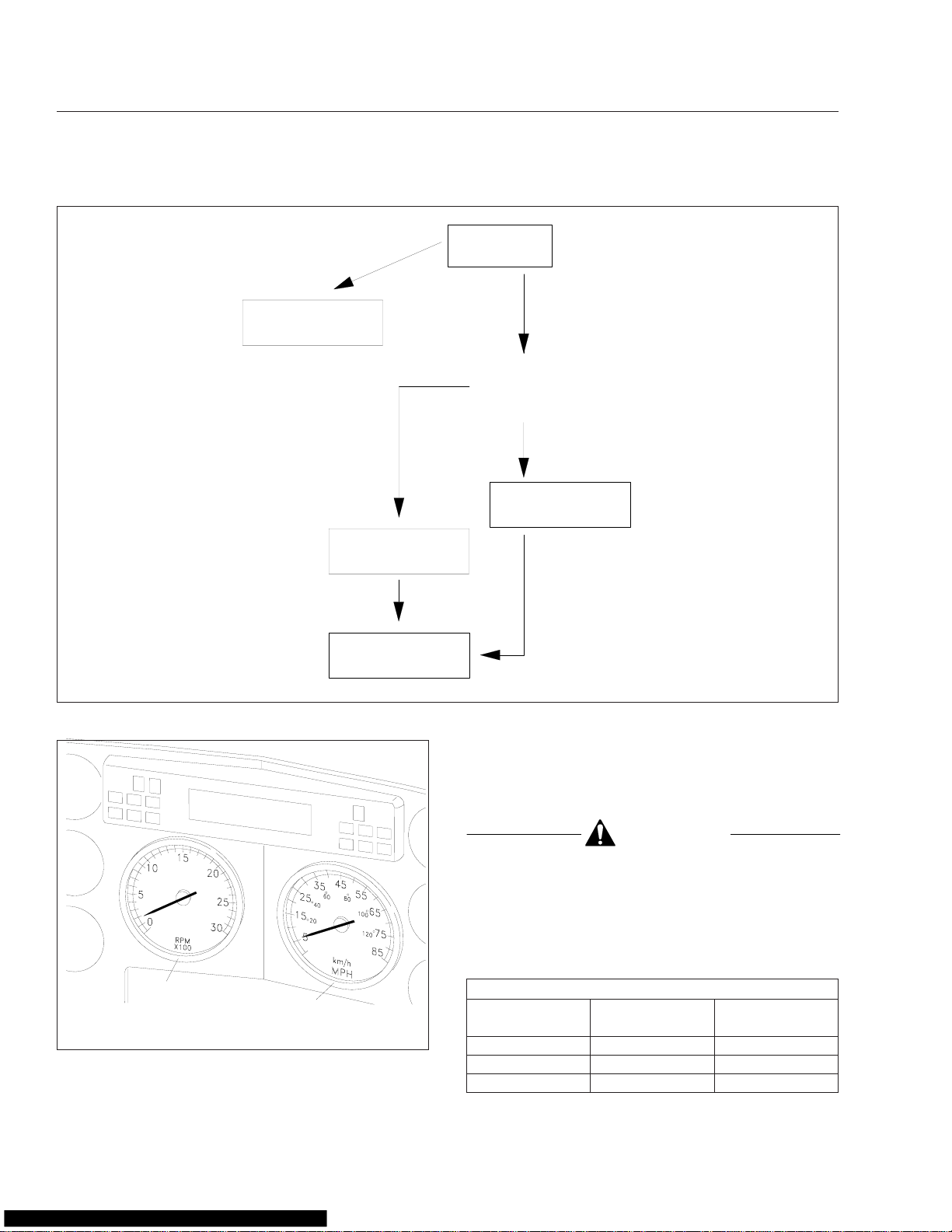
Mode/Reset Switch
The mode/reset switch (Fig. 2.11) is located on the
right side of the instrument cluster. The mode/reset
switch is used to scroll through the displays on the
message display screen, and to reset the trip distance and trip hours values to zero.
PUSH−
MODE
HOLD−
RESET
09/25/99
Fig. 2.11, ICU3/ICU3 ’07 Mode/Reset Switch
f610340
POWER ON
IGNITION ON
ICU INITIALIZES
ELECTRONIC GAUGE NEEDLES
SWEEP, WARNING/INDICATOR
LIGHTS COME ON, BUZZER SOUNDS
IF FAULT DETECTED
ABS 136
FAULT CODE
SCREEN
RELEASE PARK BRAKE
f040420a
See Fig. 2.12 for the state diagram for the LCD display cycle.
NOTE: The systems diagnostics test is used by
trained personnel to retrieve fault codes and
other diagnostic information pertaining to the
vehicle.
When the odometer reading is displayed and the
parking brake is applied:
•
Press the mode/reset switch once and the trip
distance will display.
•
Press the mode/reset switch a second time
and the trip hours (engine hours) will display.
•
Press the mode/reset switch a third time and
the SELECT screen and the current units, MI
or KM, will display.
•
Press the mode/reset switch a fourth time to
return to the odometer reading.
To reset trip miles and/or trip hours to zero, press the
mode/reset switch for 1 second or longer. To toggle
between MI (miles) and KM (kilometers), press the
mode/reset switch while in the SELECT screen.
2.10
Page 19
Instruments and Controls Identification
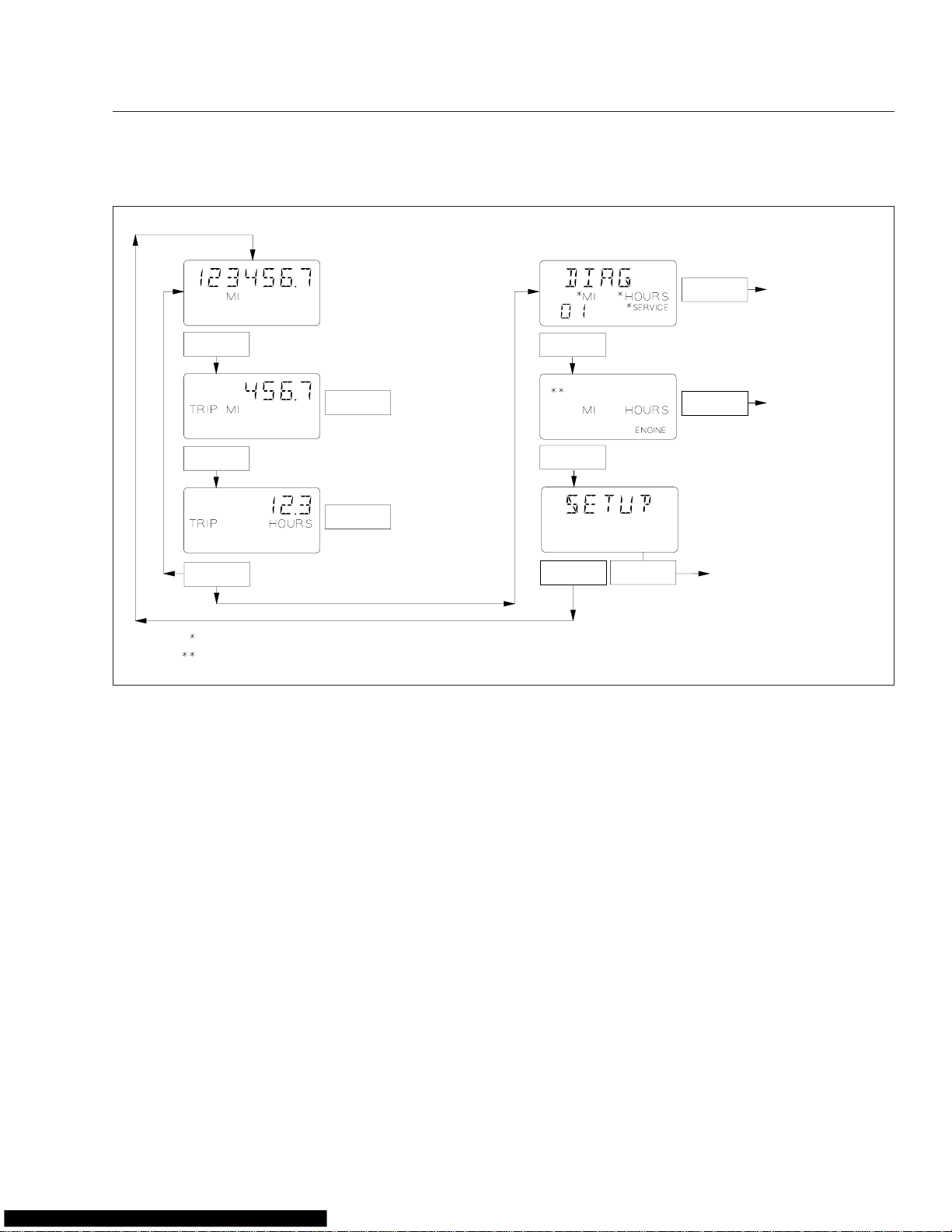
123456.7
MI
12.3 VOLTS
Push
123456.7
TRIP MI
12.3 VOLTS
Push
123456.7
TRIP HOURS
12.3 VOLTS
Push
SELECt
MI
Push
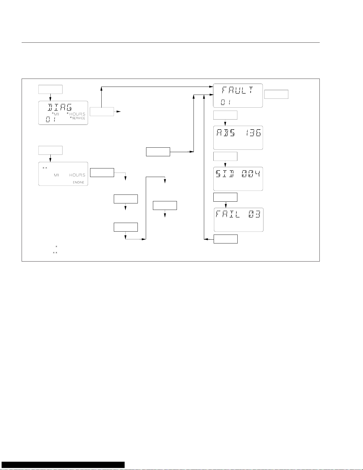
dIAG
MI HOURS
n
Push Push
03/26/2004 f040636a
Default Odometer
Dispay Screen
Hold
To Reset Trip Miles
Hold
To Reset Trip Hours
To Toggle between Units
Hold
MI<−−−−>KM
Hold
Dispay Diagnostics
n = Number of Active Fault Codes
MI = CYCLE Miles Enabled
HOURS = Cycle Hours Enabled
EC
EC
*Lo
**MI **HOURS
**no
Push
Push
Push
Push
CLEAr
123456.7
MI
123456.7
EnG oIL
SEtUP
Hold
Clear Defaults
To Dispay Total Engine Miles
EC = Engine Control
To Dispay Total Engine Hours
HOURS
EC = Engine Control
Hold
Dispay Oil Level
*Lo = Oil Level Low
HI = Oil Level High
Blank = Oil Level OK
− − = No Message
Dispay Service Interval
Hold
Cycle Screens
**MI = CYCLE Miles Active Mode
**HOURS = CYCLE Hours Active Mode
**no = Service CYCLE Inactive
Fig. 2.12, ICU3/ICU3 ’07 Mode Reset LCD Display Cycle
Instrumentation Control Unit
2L (ICU2L)
The ICU2L is a basic electronic dashboard. It can
accept information from the various sensors installed
on the vehicle and feed it to electronic gauges. Only
air gauges operate mechanically.
There can be up to 14 removable gauges on the
driver’s instrument panel (11 electronic, one electromechanical, and two mechanical). The ICU2L can
not drive gauges located on the auxiliary instrument
panel.
The dash message center is the heart of the ICU2L.
It has a set of 18 warning and indicator lights, and a
message display screen. The message display
screen is a one-line by six-character vacuum fluorescent display.
Warning and Indicator Lights
There can be up to 18 warning and indicator lights
installed in the ICU2L. See Fig. 2.13.
WARNING
When the red STOP engine lamp illuminates,
most engines are programmed to shut down automatically within 30 seconds. The driver must
immediately move the vehicle to a safe location
at the side of the road to prevent causing a hazardous situation that could cause bodily injury,
property damage, or severe damage to the engine.
CAUTION
Because operating the engine when the red engine protection light is illuminated can lead to
2.11
Page 20

Instruments and Controls Identification
1
4
7
06/26/98
Typical installation shown. Location and function of
optional lights may vary.
1. Left-Turn Indicator
2. Engine Protection
Warning and Indicator
3. Check Eng. Indicator
4. Stop Engine Warning
5. High Coolant Temp.
Warning (optional)
6. Low Oil Pressure
Warning (optional)
7. Optional Indicator 3
8. Optional Indicator 2
9. Optional Indicator 1
10. Message Display
Screen
3
2
5
6
9
8
Fig. 2.13, Dash Message Center, ICU2L
10
11. High-Beam Indicator
12. Low Air Warning
13. Right-Turn Indicator
14. Trailer ABS Warning
15. Tractor ABS Warning
16. Wheel Spin Warning
17. Park Brake On
Indicator
18. Recirc Air Warning
(optional)
19. Optional Indicator 4
11 12 13
14
15
18
17
19
16
f601458
severe engine damage, the driver must move the
vehicle to a safe location as quickly as possible.
NOTE: The functions of the ABS/ATC warning
lights are explained under "Meritor WABCO Antilock Braking System (ABS)", later in this chapter.
NOTE: The amber LANE SRCHNG warning
™
light for the optional Lane Guidance
System is
explained later in this chapter.
Ignition Sequence
If the headlights are turned on, the screen displays
the odometer and waits for the ignition to be turned
on. See Fig. 2.14.
When the ignition is turned on, all the electronic
gauges complete a full sweep of their dials, the
warning and indicator lights light up, and the buzzer
sounds for three seconds.
NOTE: The air gauges do not sweep.
The following lights illuminate during the ignition sequence:
•
Fasten Seat Belt Warning
•
Low Battery Voltage Warning
•
High Coolant Temperature Warning
•
Low Engine Oil Pressure Warning
•
Low Air Pressure Warning
•
Parking Brake On Indicator
•
All engine warning lights, including engine protection, check engine, and (Cummins only)
stop engine
•
All ABS warning lights, including wheel spin,
tractor ABS, and (if installed) trailer ABS
NOTE: Although the engine and ABS warning
lights illuminate during the ignition sequence,
they are not controlled by the ICU but by their
own system ECU (electronic control unit).
When the ignition switch has been turned on, the
ICU performs a self-test, looking for active faults.
During the first half of the self-test, all segments of
the display illuminate as follows: 888888.8. During
the second half of the self-test, the software revision
level is displayed.
Instruments
Tachometer
The tachometer indicates engine speed in revolutions
per minute (rpm) and serves as a guide for shifting
the transmission and keeping the engine in the appropriate rpm range. For low idle and rated rpm, see
the engine identification plate. The green band on
the tachometer indicates the best fuel economy
range. The yellow band indicates lower fuel
economy, the orange band indicates much lower fuel
economy, and the red band indicates poor fuel
economy. See Fig. 2.15.
Speedometer
The speedometer registers speed in both miles per
hour (mph) and kilometers per hour (km/h). See
Fig. 2.15.
2.12
Page 21
Instruments and Controls Identification
10/03/97
123456
ODOMETER
SCREEN
PARK BRAKE
RELEASED − MOVING
HEADLIGHTS ON
MI
IF NO FAULTS
WERE DETECTED
123456
123456
MI
MI
POWER ON
IGNITION ON
ICU PERFORMS SELFTEST:
ELECTRONIC GAUGE NEEDLES
SWEEP, WARNING/INDICATOR
LIGHTS COME ON, BUZZER SOUNDS
IF FAULT DETECTED
A/C 190
FAULT CODE
SCREEN
RELEASE PARK BRAKE
f040395
Fig. 2.14, ICU2L Ignition Sequence
1
2
1. Tachometer 2. Speedometer
Fig. 2.15, Instrument Panel, Level II (center)
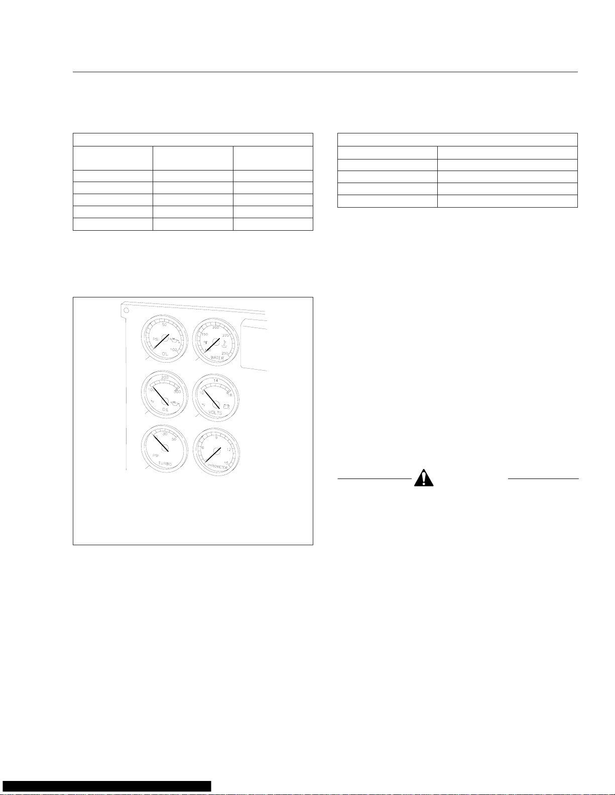
Engine Oil Pressure Gauge
The oil pressure gauge should read as shown in
Table 2.1. See Fig. 2.16.
CAUTION
A sudden decrease or absence of oil pressure
may indicate mechanical failure. Bring the vehicle
to a safe stop and investigate the cause to prevent further damage. Do not operate the engine
until the cause has been determined and corrected.
Oil Pressure
f60099309/25/95
Engine Model
Caterpillar C–10 10–20 (69–138) 30–45 (207–310)
Caterpillar C–12 10–20 (69–138) 30–45 (207–310)
Caterpillar 3406E 15 (100) min. 40 (275) min.
At Idle Speed:
psi (kPa)
*
At Rated RPM:
psi (kPa)
2.13
Page 22
Instruments and Controls Identification
Oil Pressure
Engine Model
Cummins ISX 10 (69) min. 35–45 (241–310)
Cummins ISM 10 (69) min. 35–45 (241–310)
Cummins N14 10 (69) min. 35–45 (241–310)
Detroit Diesel S60 12 (83) min. 50 (345) min.
MBE4000 7 (50) 36 (250) min.
*
Oil pressures are given with the engine at operating temperature. With
the engine cold, oil pressure may be higher. Individual engines may vary
from the listed pressures; observe and record pressures when the engine
is new to create a guide for checking engine condition.
Table 2.1, Oil Pressure Specifications
At Idle Speed:
psi (kPa)
1
3
*
At Rated RPM:
psi (kPa)
2
4
Maximum Coolant Temperature
Engine Make Temperature: °F (°C)
Caterpillar 215 (101)
Cummins 220 (104)
Detroit Diesel 215 (101)
Mercedes-Benz 221 (105)
Table 2.2, Maximum Coolant Temperature
Engine Oil Temperature Gauge,
Optional
During normal operation, the engine oil temperature
gauge should read:
•
190 to 220°F (88 to 104°C) for Caterpillar engines;
•
180 to 225°F (82 to 107°C) for Cummins engines;
•
200 to 230°F (93 to 110°C) for Detroit Diesel
engines;
•
181 to 203°F (83 to 95°C) for Mercedes-Benz
diesel engines.
Under heavy loads, such as when climbing steep
grades, temperatures that exceed the normal oil temperature range for a short period are not unusual.
See Fig. 2.16.
5
1. Engine Oil Pressure Gauge
2. Coolant Temperature Gauge
3. Engine Oil Temperature Gauge (optional)
4. Voltmeter
5. Turbocharger Boost Pressure Gauge (optional)
6. Pyrometer (optional)
Fig. 2.16, Instrument Panel Gauges (left side)
6
f60112602/12/96
Coolant Temperature Gauge
During normal engine operation, the coolant temperature gauge should read 175 to 195°F (79 to
91°C). See Fig. 2.16. If the temperature remains
below 160°F (71°C) or exceeds the maximum temperature shown in Table 2.2, inspect the cooling sys-
tem to determine the cause. See the
Workshop Manual
for troubleshooting and repair pro-
Columbia
cedures.
®
CAUTION
A sudden increase in oil temperature that is not
caused by a load increase may indicate mechanical failure. Bring the vehicle to a safe stop and
investigate the cause to prevent further damage.
Do not operate the engine until the cause has
been determined and corrected.
Voltmeter
The voltmeter indicates the vehicle charging system
voltage when the engine is running and the battery
voltage when the engine is stopped. By monitoring
the voltmeter, the driver can be aware of potential
charging system problems and have them fixed before the batteries discharge enough to create starting
difficulties. See Fig. 2.16.
The voltmeter will normally show approximately 13.7
to 14.1 volts when the engine is running. The voltage
of a fully charged battery is 12.7 to 12.8 volts when
2.14
Page 23
Instruments and Controls Identification
the engine is stopped. A completely discharged battery will produce only about 12.0 volts. The voltmeter
will indicate lower voltage as the vehicle is being
started or when electrical devices in the vehicle are
being used.
If the voltmeter shows an undercharged or overcharged condition for an extended period, have the
charging system and batteries checked at a repair
facility.
NOTE: Some vehicles may be equipped with a
digital display voltmeter integrated into the message display screen, instead of a voltmeter
gauge.
Turbocharger Boost Pressure Gauge,
Optional
A turbocharger boost pressure gauge measures the
pressure in the intake manifold, in excess of atmospheric pressure, being created by the turbocharger.
See Fig. 2.16.
Pyrometer, Optional
A pyrometer registers the exhaust temperature near
the turbocharger. See Fig. 2.16. Normal exhaust
temperatures are listed in Table 2.3.
Variations in engine load can cause exhaust temperatures to vary. If the pyrometer reading shows
that exhaust temperature exceeds normal, reduce
fuel to the engine until the exhaust temperature is
reduced. Shift to a lower gear if the engine is overloaded.
Exhaust Temperature
Engine Model
Caterpillar C–10, C–12 935–1290 (500–700)
Caterpillar 3406E 900–1100 (480–595)
Cummins M11 800–1000 (430–540)
Cummins N14 750–950 (400–510)
Detroit Diesel S60 700–950 (370–510)
MBE4000 750–1022 (400–550)
Table 2.3, Typical Pyrometer Exhaust Temperature
Readings
Exhaust Temperature:
°F (°C)
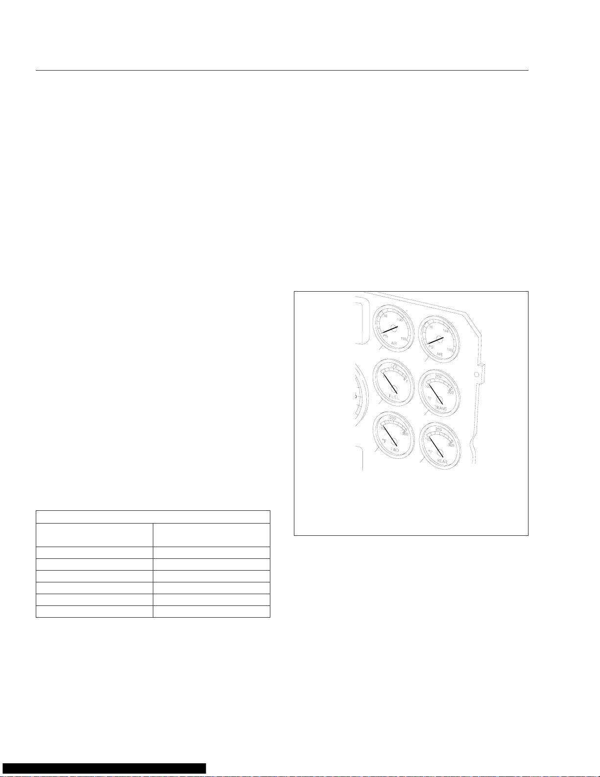
Primary and Secondary Air Pressure
Gauges
Air pressure gauges register the pressure in the primary and secondary air systems. See Fig. 2.17. Normal pressure, with the engine running, is 100 to 120
psi (689 to 827 kPa) in both systems. A low-airpressure warning light and buzzer, connected to both
the primary and secondary systems, activate when
air pressure in either system drops below a minimum
pressure of 64 to 76 psi (441 to 524 kPa). When the
engine is started, the warning light and buzzer remain on until air pressure in both systems exceeds
minimum pressure.
1
2
3
4
02/12/96
1. Primary Air Pressure Gauge
2. Secondary Air Pressure Gauge
3. Fuel Gauge
4. Transmission Oil Temperature Gauge (optional)
5. Forward Axle Oil Temperature Gauge (optional)
6. Rear Axle Oil Temperature Gauge (optional)
Fig. 2.17, Instrument Panel Gauges (right side)
5
6
f601127
Fuel Gauge
The fuel gauge indicates the level of fuel in the fuel
tank(s). See Fig. 2.17. If equipped with a second
(optional) fuel gauge, each fuel tank level is indicated
on a separate gauge.
Transmission Oil Temperature Gauge,
Optional
2.15
During normal operation, the transmission oil temperature gauge reading should not exceed 250°F
Page 24
Instruments and Controls Identification
(121°C) for Eaton®Fuller®transmissions. See
Fig. 2.17.
CAUTION
A sudden increase in oil temperature that is not
caused by a load increase may indicate mechanical failure. Bring the vehicle to a safe stop and
investigate the cause to prevent further damage.
Do not operate the engine until the cause has
been determined and corrected.
Forward and Rear Axle Oil
Temperature Gauges, Optional
During normal operation, forward and rear axle oil
temperature gauges should read between:
•
160 and 220°F (71 and 104°C) for Meritor
drive axles;
•
180 and 200°F (82 and 93°C) for Dana Spicer
drive axles.
Under heavy loads, such as when climbing steep
grades, temperatures up to a maximum of 250°F
(121°C) are not unusual. See Fig. 2.17.
™
vice inH
replaced.
O
,inTable 2.4, the air cleaner needs to be
2
NOTE: Rain or snow can wet the filter and
cause a higher than normal reading temporarily.
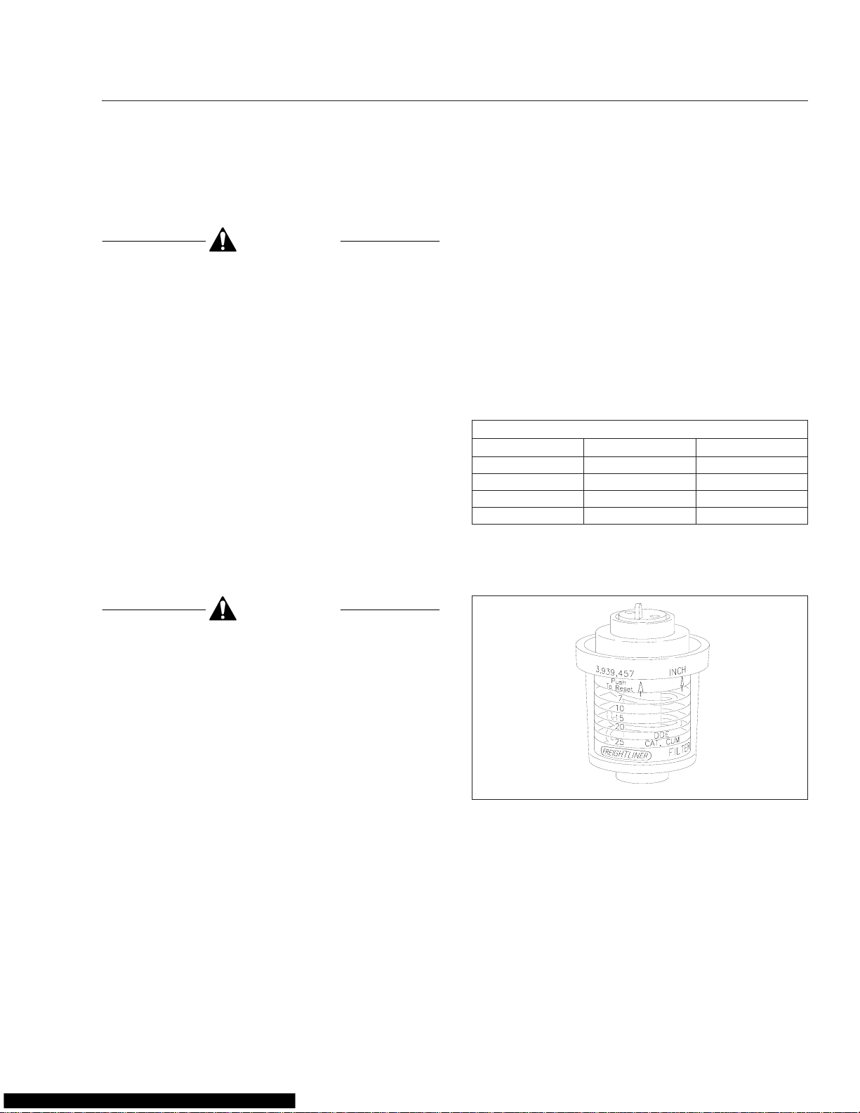
Intake-Air Restriction Indicator
An intake-air restriction indicator measures the
vacuum on the engine side of the air cleaner at the
air cleaner outlet. See Fig. 2.18. If the yellow signal
stays locked at or above the values shown in
Table 2.4 after the engine is shut down, the air
cleaner needs to be serviced. The indicator then
needs to be reset by pressing the yellow button.
Intake-Air Restriction Vacuum Readings
*
Engine Make
Cummins 12 25
Detroit Diesel 12 20
®
Caterpillar 15 25
Mercedes-Benz 10 22
*
Turbocharged engines must be checked at full load and governed en-
gine speed.
Table 2.4, Intake-Air Restriction Vacuum Readings
Initial inH2O
Service inH
O
2
CAUTION
A sudden increase in oil temperature that is not
caused by a load increase may indicate mechanical failure. Bring the vehicle to a safe stop and
investigate the cause to prevent further damage.
Do not operate the engine until the cause has
been determined and corrected.
Application Air Pressure Gauge,
Optional
An application air pressure gauge registers the air
pressure being used to apply the brakes and should
be used for reference only. The gauge will not register air pressure until the foot brake pedal is depressed or the trailer hand brake is applied.
Intake-Air Restriction Gauge, Optional
An intake-air restriction gauge measures the vacuum
on the engine side of the air cleaner at the air
cleaner outlet. Vacuum is measured in inH
of water). When the vacuum reading in normal operation equals the applicable level shown under
O (inches
2
Ser-
01/18/95
Fig. 2.18, Intake-Air Restriction Indicator
f600148a
NOTE: Rain or snow can wet the filter and
cause a higher than normal reading temporarily.
Ammeter, Optional
An ammeter measures current flowing to and from
the battery. When the batteries are being charged,
the meter needle moves to the plus side of the
gauge; when the batteries are being discharged, the
2.16
Page 25

Instruments and Controls Identification
needle moves to the minus side. A consistent negative reading when the engine is running indicates a
possible problem with the charging system.
Analog Clock
The analog clock features electronic setting. Do not
pull the set knob. The time can be set either forward
(turn knob to the right) or backward (turn the knob to
the left). A slight turn of the knob either right or left
will change the setting of the clock one minute at a
time. Holding the knob to either the right or the left
will allow accelerated sweeping of the hands for setting the hour.
Digital Clock, Optional
The digital clock has black characters on a constantly backlighted green display, with a brightness
that automatically adjusts for day or night. The clock
has a 24-hour alarm with a three-minute snooze feature.
1.
To set the time of day:
1.1
Push the run/set (lower) switch to the right
(TIME-SET position).
NOTE: When the hour setting is for a time
between noon and midnight, the small letters
PM will appear in the lower left corner of the
display; no PM indicates an a.m. setting.
1.2
Advance the hour setting to the correct
number by pushing and releasing the hour
button as many times as needed. Or if the
button is pressed and held in for longer
than two seconds, the numbers will continue to advance until the button is released.
1.3
Advance the minute setting by repeatedly
pushing, or pushing and holding the
minute button as needed.
1.4
Push the run/set switch to the middle
(RUN) position.
2.
To set the alarm time:
2.1
Push the run/set switch to the left
(ALARM-SET position).
2.2
Set the alarm time by using the same procedure that you used to set the time of
day. Remember to set the hour for a.m.
(no letters in the corner of the display) or
p.m. as desired.
2.3
Return the run/set switch to the middle
(RUN) position. The readout will return to
the time-of-day setting.
3.
To operate the alarm:
3.1
With the alarm time set, push the alarm
(upper) switch to the left. An alarm
symbol, and the letters AL, will appear in
the upper left corner of the display when
the alarm is on.
3.2
When the displayed time of day coincides
with the alarm time, the alarm will sound.
If the SNOOZ button is not pushed or the
alarm switch is not moved, the alarm will
automatically stop sounding after one
minute and will not sound again for 24
hours.
3.3
If desired, press the SNOOZ button while
the alarm is sounding to shut the alarm off
for three minutes. The alarm symbol will
flash in the display when the button is
pushed and will continue to flash until the
alarm switch is moved or the alarm has
sounded for one minute. The snooze procedure can be done as many times as
desired.
3.4
Move the alarm switch to the right when
you wish to shut off or cancel the alarm;
the alarm symbol will disappear.
wave
Controls
Ignition Switch and Key
The ignition switch has four positions: ACCESSORY,
OFF, ON, and START. The ignition key locks and unlocks the cab doors, baggage door(s), and if
equipped, the bunk door(s).
In the OFF position, the key slot is vertical; the key
can be inserted and removed only in this position.
The low-beam headlights, taillights, brake lights, road
lights, dome lights, clearance lights, turn signals,
hazard lights, refrigerator, fuel heater, electric oil pan
2.17
Page 26
Instruments and Controls Identification
heater, and electric or diesel-fired engine-coolant preheaters can be operated in the off position (regardless of whether the key is inserted).
In the ACCESSORY position, the key is turned counterclockwise. The auxiliary (bunk) fan, windshield
fan(s), radio or stereo system, mirror heat, ether start
system, air dryer, backup lights, and all of the electrical systems that are operable in the off position are
operable in the accessory position.
In the ON position, the key is turned clockwise and
all electrical systems are operable. The low air pressure and low oil pressure warning lights (or messages) and buzzer operate until the engine is started
and pressure is built up.
05/23/95
f260316
Cruise Control
IMPORTANT: On vehicles with Eaton VORAD
Collision Warning System (CWS) with SmartCruise, see the "Collision Warning System"
headings in this chapter before operating cruise
control.
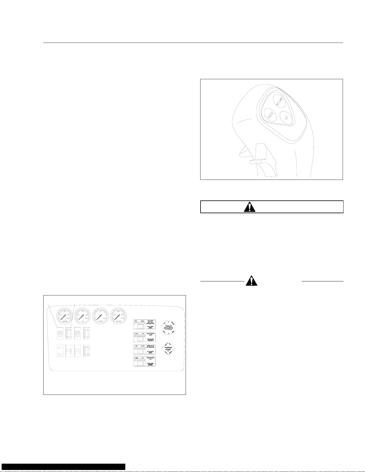
The cruise control is activated by the SPD CNTL (on/
off) and RSM/ACC–SET/CST switches on the dash
or
(Fig. 2.19),
SET buttons on the transmission shift knob
(Fig. 2.20). The minimum speed at which cruise control can be used is 30 mph (48 km/h). The minimum
and maximum speed cruise control set limits can be
programmed, by authorized personnel, into the engine electronics.
1
07/29/98
1. RSM/ACC–SET/CST Switch
2. SPD CNTL (On/Off) Switch
Fig. 2.19, Cruise Control Switches, Dash-Mounted
by optional PAUSE, RESUME, and
2
f541126
Fig. 2.20, Cruise Control, Transmission Shift Knob
Buttons
WARNING
Do not use the cruise control system when driving conditions do not permit maintaining a constant speed, such as in heavy traffic or on roads
that are winding, icy, snow-covered, slippery, or
roads with a loose driving surface. Failure to follow this precaution could cause a collision or
loss of vehicle control, possibly resulting in personal injury or property damage.
CAUTION
Do not attempt to shift gears without using the
clutch pedal when the cruise control is engaged.
Failure to follow this precaution will result in a
temporarily uncontrolled increase in engine
speed; transmission damage and gear stripping
could result.
1.
To cruise at a particular speed:
1.1
Press the upper half of the SPD CNTL
(on/off) rocker switch on the instrument
control panel.
1.2
Hold the throttle down until the speedometer reaches the desired speed.
1.3
Momentarily flip the RSM/ACC–SET/CST
paddle switch on the instrument control
panel down to SET/CST.
1.4
or
—Push the SET button on the transmis-
sion shift knob.
2.18
Page 27

Instruments and Controls Identification
2.
To disengage the cruise control:
2.1
Depress the brake pedal or clutch pedal.
2.2
or
—Press the lower half of the SPD CNTL
rocker switch on the instrument control
panel.
2.3
or
—Push the PAUSE button on the transmission shift knob.
3.
To resume a preselected cruise speed:
3.1
If the SPD CNTL rocker switch on the instrument control panel is off, turn it on.
3.2
Momentarily flip the RSM/ACC–SET/CST
paddle switch on the instrument control
panel to RSM/ACC.
3.3
or
—Push the RESUME button on the
transmission shift knob. Cruise will return
to the last speed selected.
NOTE: The resume vehicle speed memory is
not maintained if the ignition is shut off.
4.
To adjust cruise speed up or down:
4.1
Hold the paddle switch on the instrument
control panel at RSM/ACC to accelerate,
or at SET/CST to decelerate, until the desired speed is reached.
4.2
or
—Press the SET button on the transmission shift knob to accelerate, or the RESUME button to decelerate, until the desired speed is reached.
1.3
Momentarily flip the paddle switch on the
instrument control panel down to SET/
CST.
1.4
or
—Push the SET button on the transmis-
sion shift knob.
2.
To disengage the PTO:
2.1
Depress the brake pedal or clutch pedal.
2.2
or
—Press the lower half of the SPD CNTL
rocker switch on the instrument control
panel.
2.3
or
—Press the PAUSE button on the shift
knob.
3.
To resume a previously selected engine speed:
3.1
If the SPD CNTL switch on the instrument
control panel is turned off, turn it on.
3.2
Momentarily flip the paddle switch on the
instrument control panel up to RSM/ACC.
3.3
or
—Press the RESUME button on the
transmission shift knob.
4.
To adjust engine speed up or down:
4.1
Hold the RSM/ACC–SET/CST paddle
switch up to accelerate, or down to decelerate, until the desired speed is reached.
4.2
or
—Press the SET button on the transmission shift knob to accelerate, or the RESUME button to decelerate, until the desired speed is reached.
Power Takeoff (PTO) Governor
Caterpillar electronic engines may be equipped with
a PTO governor. This mode is used only when the
vehicle is parked. The PTO mode is activated by the
SPD CNTL and RSM/ACC–SET/CST switches on the
dash (Fig. 2.19) or by optional PAUSE, RESUME,
and SET buttons on the transmission shift knob
(Fig. 2.20).
1.
To engage the PTO:
1.1
Press the upper half of the SPD CNTL
rocker switch on the instrument control
panel.
1.2
Hold the throttle down until the tachometer
reaches the desired engine speed.
2.19
NOTE: The resume engine speed memory is
not maintained if the ignition is shut off.
Detroit Diesel Electronic Engine
Control (DDEC IV
IMPORTANT: This vehicle is equipped with an
Instrumentation Control Unit (ICU) that provides
warning messages and diagnostic fault codes.
See "Instrumentation Control Unit", depending
on the type of unit installed in your vehicle.
The DDEC IV system uses a computer that is programmed to automatically control engine timing and
fuel injection.
DDEC IV systems will shut down the engine if sensors indicate an emergency engine condition such as
low coolant level, high coolant temperature, or high
®
) Operator Control
Page 28
Instruments and Controls Identification
oil temperature. If such a condition occurs, the yellow
Check Engine light on the dash will illuminate. If the
problem gets bad enough to cause possible engine
damage, the DDEC IV will gradually cut engine
power down to 70 percent of original power. At that
point, the red Engine Protection (ENG PROT) light
will turn on and thirty seconds later, DDEC IV will
shut down the engine (if programmed). If DDEC IV
detects low oil pressure, both the Check Engine and
Engine Protection lights will come on, and the engine
will shut down in thirty seconds (if programmed). See
"Engine Protection—Warning and Shutdown Process" at the beginning of this chapter, for more information.
Optimized Idle
®
The Optimized Idle option on DDEC IV-equipped vehicles is a system that automatically stops and restarts the engine to accomplish the following:
•
Keep the engine oil temperature between 60 to
104°F (16 to 40°C)
•
Keep the battery charged
•
Keep the cab or sleeper at a constant, desired
temperature (if equipped with a thermostat)
The benefits of the system include reduced engine
idle time, fuel savings, reduction of exhaust emissions and noise, increased starter and engine life,
and less chance of dead batteries due to electrical
loads.
Optimized Idle operates in two modes. They are the
engine mode or the thermostat mode. The engine
mode keeps the battery charged and the engine oil
temperature within factory set limits. The thermostat
mode is the same as the engine mode, but also
keeps the cab and sleeper at a constant preset temperature.
The engine mode is always activated when the system is operated. The thermostat mode is activated
when the thermostat is turned on.
The thermostat mode controls the set point, which is
the desired temperature of the cab and sleeper, and
the comfort zone, which is the number of degrees
from the set point before the engine needs to heat or
cool the cab. There are three comfort zones: 4°F
(2°C), 7°F (4°C), or 10°F (6°C).
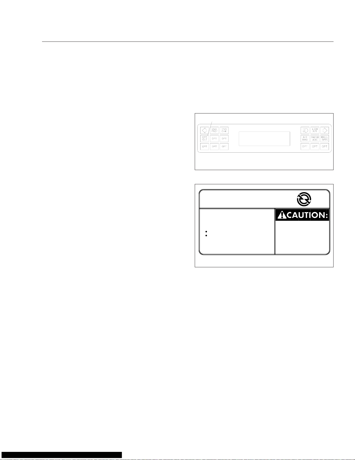
Vehicles equipped with Optimized Idle have a label
and a dash light. The dash light is on the dash mes-
sage center or the Driver Message Center, on the A
panel. See Fig. 2.21. See Fig. 2.22 for the dash
label detail. If equipped with the thermostat mode, a
thermostat is located in the sleeper, above the bunk.
See Fig. 2.23.
1
FASTEN SEATBELTS
0000432 MILES
02/11/97
1. Optimized Idle Light
Fig. 2.21, Optimized Idle Light Location
OPTIMIZED IDLE
TO USE:
− IDLE ENGINE
− CLOSE HOOD
− ENGAGE PARKING BRAKES
− PUT TRANSMISSION IN
NEUTRAL AND
HI RANGE (IF EQUIPPED)
− THEN, MOVE CRUISE SWITCH
FROM OFF TO ON
− IF DESIRED, TURN CAB
THERMOSTAT ON (IF EQUIPPED)
11/13/96
Fig. 2.22, Optimized Idle Dash Label
TM
TO AVOID
UNINTENTIONAL
VEHICLE MOVEMENT,
DO NOT MOVE SHIFT
LEVER OR RANGE
SELECTOR WHEN
OPTIMIZED IDLE IS ON
f601264
f080062
The thermostat consists of an LCD readout and four
buttons.
The display normally shows the temperature of the
sleeper, but changes accordingly as the buttons are
pressed.
The button functions are as follows:
•
Up button: increases the set point and comfort
zone.
•
Down button: decreases the set point and
comfort zone.
•
Cool/heat button: detects either cooling or
heating operation.
•
Mode button: scrolls through the various functions. It can also be used to set desired temperature values.
2.20
Page 29
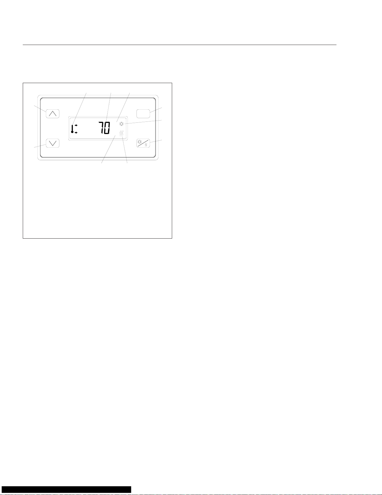
Instruments and Controls Identification
3 4
2
1
11/08/96
1. Down Button
2. Up Button
3. Upper/Lower Temperature Icon
4. Temperature Display
5. Degrees Fahrenheit Indicator
6. Mode Button
7. Cooling Icon
8. Cool/Heat Selection Button
9. Heating Icon
10. Degrees Celsius Indicator
Fig. 2.23, Optimized Idle Thermostat
1.
Activate Optimized Idle (engine mode) as fol-
10
5
MODE
°F
°C
9
lows:
1.1
Set the parking brake.
1.2
If it is tilted, close and secure the hood.
1.3
Start the engine and let it idle.
1.4
Put the transmission in neutral.
1.5
Turn on the cruise control.
IMPORTANT: The cruise control must be
after
turned on
the engine is idling. If it was
previously turned on, turn off the cruise control, then turn it on again.
1.6
The dash light will begin blinking, indicating that Optimized Idle is active. The system is now in the engine mode and after
an initial phase, in which the idle speeds
up to 1000 or 1500 rpm (depending on the
outside temperature), the engine will stop
and start automatically to keep the battery
charged and the engine oil warm. The
dash light stays on and shines steadily at
this point.
2.
Activate the thermostat mode (if so equipped) as
follows:
6
7
8
f601250
NOTE: When the system is in the thermostat
mode, it is also in the engine mode. It will
continue to operate in the engine mode even
if the thermostat mode is turned off.
2.1
With the system in the engine mode, set
the cab and sleeper heater or air conditioner controls to the highest setting.
2.2
Turn on the thermostat by touching any of
the four buttons. See Fig. 2.23.
The display will flash the current sleeper
temperature and the previous mode (cooling or heating) selected. If the cab needs
to be cooled or heated, the cool/heat icon
will flash.
2.3
Choose either cool or heat by pressing the
Cool/Heat
button. Make sure the selection
matches that of the cab controls.
IMPORTANT: If the heat or cool selection of
the thermostat does not match that of the
cab, the system will idle and cycle excessively.
2.4
Select Fahrenheit or Celsius by pressing
and holding the
the °F or °C is displayed.
2.5
Select the temperature set point by pressing either the
button, as applicable. Holding the button
will cause the display to count up or down
rapidly. When the desired set point is displayed, release the button. The set point
is stored in memory.
2.6
Select the temperature comfort zone by
pressing the
and lower temperature limit icon is displayed. Then use the
to select one of the three comfort zones of
4°F (2°C), 7°F (4°C), or 10°F (6°C).
3.
To change the display to either Fahrenheit or
Celsius, press the
or°Cicon is flashing. Press theUPor
button to change to the desired value. The main
display will appear 5 seconds after the button is
released.
4.
To deactivate the thermostat mode and return to
just the engine mode, press the
and hold it for 3 seconds.
Mode
UP
MODE
MODE
button until either
button or the
DOWN
button until the upper
UPorDOWN
button until only the
DOWN
MODE
button
°F
button
2.21
Page 30
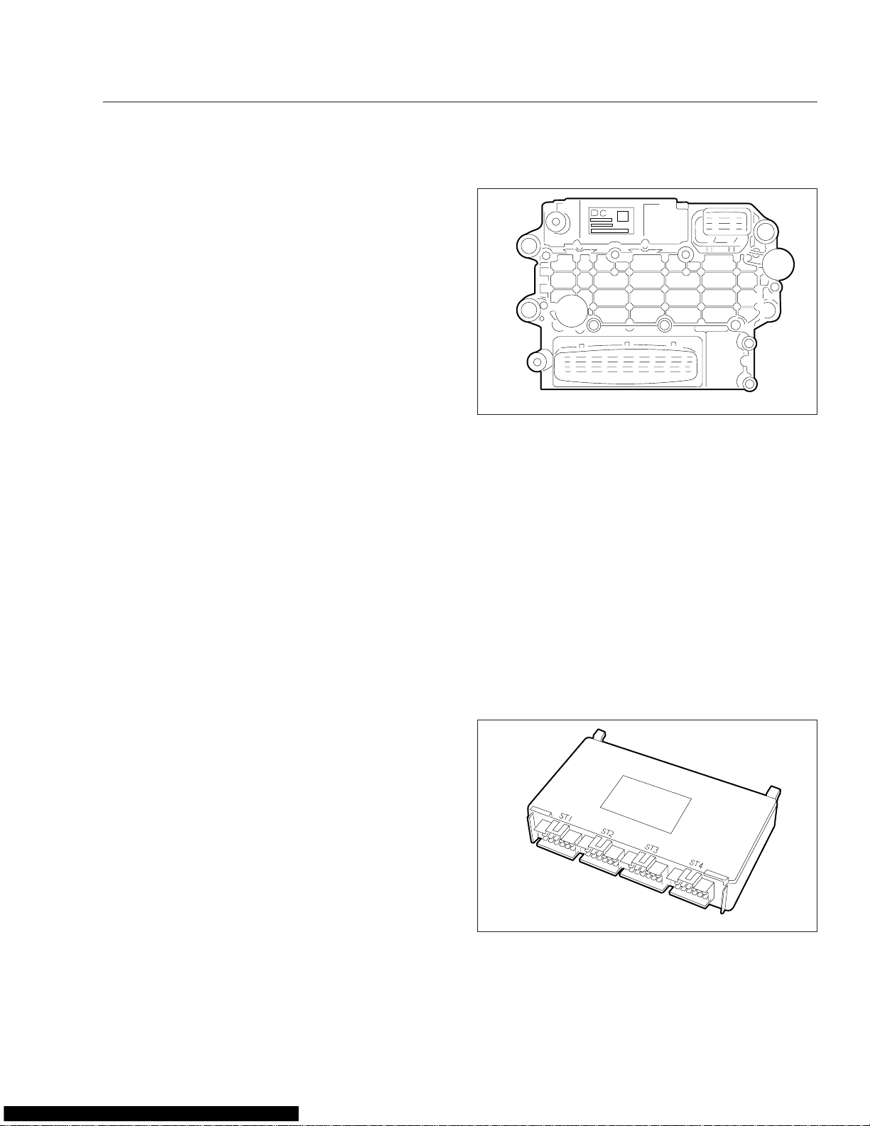
Instruments and Controls Identification
5.
To shut down Optimized Idle completely, either
turn off the ignition or use the drive away feature.
The drive away feature allows the use of all the
DDEC features. Use the drive away feature as
follows:
5.1
If the engine is running:
ing brakes or put the transmission in gear.
If the engine is not running:
gine. Release the parking brakes or put
the transmission into gear.
5.2
Let the engine return to base idle. The
active light will turn off. Optimized Idle is
now disabled and all the DDEC features
are available.
Release the park-
Start the en-
02/19/2008 f545236
Fig. 2.24, Motor Control Module (MCM)
Detroit Diesel Electronic Engine
Control (DDEC VI
Because the DDEC VI system is electronic, vehicle
battery power must be available to operate the computer. The system operates at 12 volts, however, in
the event of a power supply malfunction, the system
will continue to operate at reduced voltage. When
this occurs, the amber warning lamp (Check Engine)
will come on. The engine will operate only at reduced
rpm. When the battery reaches a point where the
Motor Control Module (MCM) hasn’t enough power to
function, the engine will shut down.
Besides the engine and its related sensors, the
DDEC VI system has two control modules:
•
a Motor Control Module (MCM) located on the
engine;
•
a Common Powertrain Controller (CPC) located in the vehicle cab.
The two control units are connected by a proprietary
datalink, through which all necessary data and information is exchanged. The CPC broadcasts information on the J1587 and J1939 datalinks, where it is
read by the diagnostic tool. The MCM monitors both
the engine and datalink. When a malfunction is detected, the system selects an appropriate response;
for example the emergency-running mode may be
activated.
®
) Operator Control
The MCM processes the data received from the
CPC; for example, the position of the accelerator
pedal, engine brake, etc. This data is evaluated together with the data from the sensors on the engine,
such as coolant and fuel temperature, and oil and
charge pressure. The data is then compared to the
characteristic maps stored in the MCM. From this
data, the quantity and timing of fuel injection are calculated.
Common Powertrain Controller (CPC)
The CPC is located in the vehicle cab. See
Fig. 2.25. The CPC communicates with the MCM,
over the J1939 datalink. Data for specific applications
is stored in the CPC. These include idle speed, maximum running speed, and speed limitation.
02/19/2008 f545235
Motor Control Module (MCM)
The MCM is located on the left-hand side of the engine. See Fig. 2.24.
Fig. 2.25, Common Powertrain Controller (CPC)
The CPC receives data from the following sources:
2.22
Page 31

Instruments and Controls Identification
•
the operator (accelerator pedal position, engine
brake switch, etc.);
•
other electronic control units (for example, the
antilock brake system);
•
the MCM (oil pressure, coolant temperature,
etc.).
California Engine Idle Limiting
In order to meet the California engine idle limiting
standard, an engine idle shutdown feature has been
built into the DDEC VI engine control strategy. When
the California engine idle limiting feature is enabled,
the engine will generally shut down after 5 minutes of
continuous idling when the transmission is in neutral
or park, and the parking brake is set, or after fifteen
minutes when the transmission is in neutral or park,
and the parking brake is not set.
Pressing the service-brake pedal, clutch pedal, stopengine override switch, and accelerator pedal, or
changing the parking brake status, during the final 30
seconds before a shutdown would otherwise occur,
will prevent the engine from shutting down, and reset
the shutdown timer. After an automatic shutdown, the
engine may be restarted and operated normally.
If a parked regen of the aftertreatment system is initiated, it will override the five-minute idle shutdown.
The HEST lamp will flash every ten seconds, indicating a regeneration is in progress, and the driver is
not controlling the engine idle.
The automatic shutdown feature is generally disabled
on engines certified by the U.S. EPA for use outside
California.
Idle Shutdown Timer
This feature is an optional 1-to-100 minute idle shutdown system. Its purpose is to conserve fuel by
eliminating excessive idling, and allowing a turbocharger cool-down period. To activate the shutdown,
the transmission must be in neutral with the vehicle
parking brakes set and the engine in idle or fast-idle
mode.
Data Recording Capability
DDEC VI contains the ability to extract detailed data
on the engine use and performance, using DDEC
Reports software. This data, known as DDEC Data,
is stored in the CPC and contains information on engine performance (such as fuel economy, idle time,
time in top gear), and critical incidents (such as detailed diagnostic data records and hard braking
events). DDEC Data can be downloaded using
DDEC Reports software to produce reports. See the
Detroit Diesel DD15 Engine Operator’s Guide
complete details.
for
Flashing Malfunction Codes
All malfunction codes are four digits. The malfunction
code recorded in the computer memory will remain
until it is erased by a technician. The flashing malfunction code can also be obtained by the operator.
See the
Guide
Detroit Diesel DD15 Engine Operator’s
for complete details.
Engine Brake
The engine brake is enabled by an ON/OFF switch,
with a separate intensity switch to select low, medium, or high braking power.
WARNING
To avoid injury from loss of vehicle control, do
not activate the engine brake system under the
following conditions:
•
on wet or slippery pavement, unless the vehicle is equipped with antilock braking system
(ABS) and you have had prior experience driving under these conditions;
•
when driving without a trailer or pulling an
empty trailer;
•
if the tractor drive wheels begin to lock, or
there is fishtail motion after the engine brake is
activated.
If the engine is equipped with both cruise control and
an engine brake, the engine brake can operate automatically while in cruise control mode. If the cruise
control/engine brake function is turned on in the
DDEC VI system programming, the engine brake will
come on "low" when the set road speed increases a
few miles-per-hour (kilometers-per-hour) above the
cruise set speed. The maximum amount of braking
(low, medium, high) is selected with the dash
switches. When the vehicle returns to the set cruise
speed, the engine brake will turn off.
The engine brake will only operate when the accelerator pedal is fully released. Disengaging the clutch
will prevent the engine brake from operating.
2.23
Page 32

Instruments and Controls Identification
Vehicles equipped with antilock braking systems
(ABS) have the ability to turn the engine brake off if
a wheel-slip condition is detected. The engine brake
will automatically turn itself back on once the wheel
slip is no longer detected. The DDEC VI system will
deactivate the engine brake system when the engine
speed falls below 1000 rpm or when the vehicle
slows down to a preset speed, depending on DDEC
programming. This prevents stalling the engine.
For safety reasons, do not use cruise control when it
is not possible to keep the vehicle at constant speed
due to:
•
Winding roads
•
Heavy traffic
•
Slippery pavement
•
Descending grades calling for engine brake
assistance
For a detailed explanation of the engine brake operation, see the
Guide
.
Detroit Diesel DD15 Engine Operator’s
Caterpillar C–10, C–12, and 3406E
Electronic Engine Operator Control
IMPORTANT: This vehicle is equipped with an
Instrumentation Control Unit (ICU) that provides
warning messages and diagnostic fault codes.
See "Instrumentation Control Unit", depending
on the type of unit installed in your vehicle.
The Caterpillar C–10, C–12, and 3406E electronic
engines use a computer (electronic control module)
to automatically control engine timing and fuel injection. The electronic features of these engines include
an electronic governor, fuel-to-air ratio control, programmable engine ratings, injection timing control,
fault analysis and recording, and a datalink used for
programming the electronic control module and
troubleshooting the system.
All Caterpillar electronic engines have an engine
check light located above the speedometer and tachometer. This warning light comes on or flashes if
the engine oil pressure is low, the coolant temperature is high, the intake manifold air temperature is
high, the coolant is low (optional), or whenever there
is a problem within the electronic engine system.
Some vehicles equipped with Caterpillar electronic
engines have an automatic engine shutdown option.
This option will shut off fuel to the engine if poten-
tially damaging conditions are detected. See "Engine
Protection—Warning and Shutdown Process" at the
beginning of this chapter, for more information. See
the Caterpillar electronic engine troubleshooting
manual for troubleshooting procedures.
BrakeSaver Control, Optional
The BrakeSaver (optional on Caterpillar 3406E engines) is operated by a lever mounted in the cab.
The lever controls the amount of oil being directed
through the BrakeSaver. The time required to fill the
BrakeSaver with oil pressure to the point of maximum braking in the BrakeSaver is approximately 1.8
seconds.
Cummins CELECT™Plus Electronic
Engines Operator Control
IMPORTANT: This vehicle is equipped with an
Instrumentation Control Unit (ICU) that provides
warning messages and diagnostic fault codes.
See "Instrumentation Control Unit", depending
on the type of unit installed in your vehicle.
Cummins CELECT Plus is an electronic fuel control
system. These electronic engines are controlled by a
microprocessor-based computer. This computer controls specific engine and vehicle speed modes of operation to maximize vehicle fuel economy and performance.
Vehicles with these engine systems have three indicator lights: a yellow check engine light, a red stop
engine light, and an engine protection (engine fluids)
light. These indicators are located in the lightbar
above the speedometer and tachometer. With the
ignition switch on, the indicator lights come on for
about two seconds; then, if there is no problem with
the engine system, the lights will go out. Whenever
there is a problem within the electronic engine system, one of the lights will come on and stay on as
long as the problem exists. See "Engine Protection—
Warning and Shutdown Process" at the beginning of
this chapter, for more information.
Suspension Seat Adjustment Controls
Due to the maximum adjustability of mid- and highback air suspension seats, it is possible to combine
the seat back recline adjustment and the seat slide
adjustment so that the seat back contacts the backwall. It is the responsibility of the driver to adjust the
2.24
Page 33

Instruments and Controls Identification
seat to prevent damage to the seat and the cab interior.
All adjustment controls for a suspension seat are located on the seat base. See Chapter 5 for complete
instructions.
Tilt Steering Wheel, Optional
The optional tilt steering wheel control pedal is located to the left of the clutch pedal. See Fig. 2.26.
2
Parking Brake Control Valve and
Trailer Air Supply Valve
The yellow diamond-shaped knob operates the parking brake valve. Pulling the knob applies both the
tractor and the trailer spring parking brakes. See
Fig. 2.27. Pushing the knob in releases the tractor
spring parking brakes. Before the spring parking
brakes can be released, the air pressure in either air
brake system must be at least 65 psi (447 kPa).
1
03/10/99
1. Trailer Air Supply Valve Knob
2. Parking Brake Control Valve Knob
Fig. 2.27, Brake Valve Knobs
2
f610291
A
11/14/95
A. Driver’s Door Opening
1. Adjustment Valve 2. Air Line Connections
Fig. 2.26, Tilt Steering Wheel Control Pedal
After adjusting the seat to the desired ride position,
unlock the steering column by pushing and holding
the control pedal all the way down. Tilt the steering
column to the desired position, then release the control pedal to lock the steering column in place.
1
f461069
WARNING
Make sure that the steering column is locked before driving the vehicle. Never tilt the column
while driving the vehicle. Doing so could cause
loss of vehicle control, personal injury, and property damage.
CAUTION
Do not step on the service brake pedal while the
parking brakes are applied. To do so can cause
damage to the brake mechanisms.
The red octagonal-shaped knob operates the trailer
air supply valve. See Fig. 2.27. After the vehicle and
its air hoses are connected to a trailer and the pressure in the air system is at least 65 psi (447 kPa),
the trailer air supply valve knob must be pushed in
(and should stay in) to charge the trailer air supply
system and release the trailer spring parking brakes.
Before disconnecting a trailer or when operating a
vehicle without a trailer, the trailer air supply valve
knob must be pulled out.
See Chapter 6 under the heading "Brake System"
for instructions regarding use of the trailer air supply
valve and parking brake valve.
Power Mirrors
Both outside mirrors can be equipped with an electrical remote control. Operate the driver door-mounted
switch to adjust the mirror.
2.25
Page 34

Instruments and Controls Identification
Mirror Heat Switch, Optional
One or both outside door mirrors can be heated to
keep them defrosted. When the mirror heat (MIRR
HEAT) switch is on, an amber indicator light illuminates in the switch.
Heater/Air-Conditioner Controls
Heater/air conditioner controls consist of a fourspeed fan switch, an air selection switch, a temperature control switch, and a fresh-air/recirculation
switch. See Fig. 2.28. See Chapter 4 for detailed
operating instructions of the heater/air conditioner.
1
10/26/95 f830717
5
1. Fan Switch
2. Air Selection Switch
3. Temperature Control Switch
4. Fresh-Air/Recirculation Switch
5. Auxiliary (sleeper bunk) Switch
Fig. 2.28, Heater/Air Conditioner Controls
4
2
3
Left and Right Windshield-Fan
Switches, Optional Ceiling-Mounted
Fans
Ceiling-mounted defogger fans are operated by
LOW/OFF/HIGH toggle switches located in the base
of the fan.
Turn Signal Lever
The turn signal lever is mounted on the steering column. See Fig. 2.29. Moving the lever counterclockwise turns on the left-turn signal lights; moving it
clockwise turns on the right-turn signal lights. When
one of the turn signal lights is on, a green indicator
light flashes at the far left or far right of the warning
and indicator light panel. To cancel the signal, move
the lever to the neutral position. Some style levers
may have automatic cancelling, and the turn signal
lever automatically returns to the neutral position
when the steering wheel returns to the straight-ahead
position after a turn.
1
3
9/26/95 f461056
1. Turn Signal Lever
2. Trailer Brake Hand Control Valve Lever
3. Hazard Warning Light Switch Tab
Fig. 2.29, Steering Column-Mounted Controls
2
Ether Start, Optional
For cold-weather starting, the vehicle may be
equipped with an automatic ether start system. Always see the instructions in the manufacturer’s engine operation manual for information before using
ether. Some electronic engines do not allow the use
of ether.
Cigarette Lighter
Push in the lighter to heat the element. The lighter
will stay in and will automatically pop out when the
element is hot.
CB Radio Connections
An antenna connection and positive (+) and negative
(–) power connections are provided for a CB radio.
Trailer Brake Hand Control Valve
Lever
The trailer brake hand control valve lever is used for
applying the trailer brakes without applying the truck
or tractor brakes and is mounted on the steering column. See Fig. 2.29. See Chapter 6 under the heading "Brake System" for operating instructions.
2.26
Page 35

Instruments and Controls Identification
Transmission Controls
If so equipped, the transmission range control valve
and splitter valve are attached to the gearshift knob.
Transmission shift pattern labels are located inside
the cab. For control of the automated mechanical
transmissions, use the Freightliner SmartShift
Transmission Shift Control mounted on the steering
column. See Chapter 8 for complete transmission
operating instructions.
Freightliner SmartShift™Transmission
Shift Control
The SmartShift transmission shift control is an electronic transmission control device. It is applicable to
both automated mechanical and automatic transmissions but must be mated to an Eaton
™
Shift or Meritor
Engine Synchro Shift (ESS) transmission. It replaces either the typical floor-mounted
shift lever or dash-mounted push button control. The
SmartShift control mounts to the right-hand side of
the steering column and is operated by the driver’s
right hand. See Fig. 2.30 and Fig. 2.31. SmartShift
accepts driver requests for transmission functions
and transmits them through hard wiring to the transmission control unit (TCU).
SmartShift offers advantages over conventional
transmission control devices; usable cab space is
increased and access to the sleeper is improved by
removing the shift lever from the floor. Also, because
of the steering column mounting, the transmission
control is within fingertip reach of the steering wheel,
which enhances safety.
SmartShift is a true shift-by-wire system. Manual
gearshifts (all ESS and AutoShift when in manual
mode) are accomplished by a momentary pull or
push on the control in the plane perpendicular to the
steering wheel. See Fig. 2.32. Pull upward (toward
you) on the control to upshift and push downward
(away from you) to downshift. For the Eaton Fuller
AutoShift transmission, a four-position (R, N, D, L)
linear mode selector switch is located at the end of
the control. See Fig. 2.30. For the Meritor ESS transmission, a three-position (R, N, F) linear mode selector switch is located at the end of the control. See
Fig. 2.31. The control is spring-loaded and returns to
mid-position when released after an upshift or
downshift.
®
™
Fuller®Auto-
5
4
3
1
11/23/99
1. SmartShift Control
2. Forward Driving Mode Switch (slide switch)
3. MAN Switch Position
4. AUTO Switch Position
5. Upshift Direction (in manual mode, pull upward)
6. Reverse Selector Position
7. Mode Selector Switch
8. Neutral Selector Position
9. Drive Selector Position
10. Low Selector Position
11. Downshift Direction (in manual mode, push
downward)
Fig. 2.30, SmartShift Control (for Eaton Fuller AutoShift
1
11/23/99
1. SmartShift Control
2. Upshift Direction (pull upward)
3. Reverse Selector Position
4. Mode Selector Switch
5. Neutral Selector Position
6. Forward Selector Position
7. Downshift Direction (push downward)
Fig. 2.31, SmartShift Control (for Meritor Engine
Synchro Shift transmissions)
2
transmission)
Smart
Shift
2
SHIFT
UP
PULL
PUSH
SHIFT
DOWN
6
7
8
9
10
11
f270082
3
4
5
6
7
f270081
Engine Brake Switch, Optional
The engine brake (ENG BRK) switch controls the
degree of engine braking. See Chapter 7 under the
2.27
Page 36

Instruments and Controls Identification
2
1
3
R
N
D
4
5
06/03/99
1. Upshift (in manual mode, pull upward)
2. Steering Wheel
3. Reverse Position
4. Neutral Position
5. Drive Position
6. Downshift (in manual mode, push downward)
7. Steering Column
Fig. 2.32, SmartShift Control Operation (Eaton Fuller
AutoShift control, showing only R, N, D positions)
6
7
f270065
heading "Engine Braking Systems" for additional
information.
Exhaust Brake Switch, Optional
The optional exhaust brake is controlled by a dashmounted paddle switch to help slow the vehicle when
the throttle is released.
Engine Fan Switch, Optional
10/02/2006
Fig. 2.33, Request/Inhibit Regen Switch
f610848
The style and function of switch will vary with the engine make and model. See the engine operation
manual for operation details.
Controlled Traction Differential Control
Valve Switch
A controlled traction differential feature is included or
available as an option on some rear axles. A control
valve switch engages and disengages the controlled
traction feature to cause the axle shafts to rotate together. See Fig. 2.34. The controlled traction, or differential lock, should only be engaged when the vehicle is moving slowly at low throttle to avoid causing
internal axle damage. The differential lock must only
be used for adverse road conditions. The use of the
lock increases the turning radius and affects the vehicle handling. A guard is positioned around the
switch to minimize accidental activation. See Chap-
ter 9 for complete operating instructions.
The engine cooling fan can be turned on by the engine fan (ENG FAN) switch. The fan will continue to
operate for a set amount of time and then turn off
unless the coolant temperature is high enough to
continue the fan operation.
Aftertreatment System (ATS)
Request/Inhibit Regen Switch
A parked regen of the ATS can be initiated with the
request/inhibit regen switch. It may also be used to
inhibit the vehicle from performing an automatic
regen. See Fig. 2.33.
09/26/95 f350142
Fig. 2.34, Controlled Traction Differential Switch
2.28
Page 37

Instruments and Controls Identification
Interaxle Differential Lockout Control
Valve Switch
CAUTION
The interaxle lock should only be engaged when
the vehicle is moving slowly at low throttle. Engagement at high speed or power can damage
the axle(s).
The interaxle lock, standard on all dual-drive vehicles, is driver-actuated by means of a LOCK/
UNLOCK control valve switch mounted on the control
panel. See Fig. 2.35. A red indicator light comes on
whenever the interaxle differential is locked out
(switch is in the lock position; no differential action
between the drive axles). A guard around the switch
minimizes accidental activation.
9/07/95 f310489
Fig. 2.36, Fifth Wheel Air Slide Switch
Do not activate the fifth wheel slide control valve
while the vehicle is in motion. To do so could
cause damage to the fifth wheel member, the
kingpin, the cab or trailer, and ultimately to the
drivetrain.
CAUTION
09/26/95
Fig. 2.35, Interaxle Differential Lockout Switch
f350141
Fifth Wheel Air Slide Control Valve
Switch, Optional Air-Operated Sliding
Fifth Wheel
The fifth wheel air slide valve permits repositioning of
the sliding fifth wheel from inside the cab. Moving the
air slide control valve switch to the lock position deactivates the control valve and locks the fifth wheel
to the baseplate. See Fig. 2.36. Moving the switch to
the unlock position activates the control valve and
unlocks the fifth wheel slide mechanism, allowing
changes to the total length of the tractor-trailer and
changes to axle loads to comply with varying state or
provincial laws. A red indicator light, if so equipped,
is illuminated whenever the fifth wheel slide is unlocked. A guard is positioned around the switch to
minimize accidental activation.
Air Suspension Dump Valve, Optional
The air suspension dump valve allows the air in the
vehicle air suspension to be quickly exhausted, lowering the rear of the vehicle. This makes it easier to
connect to or disconnect from a trailer. To exhaust air
from the suspension, move the switch to LOWER.
When the switch is moved back to the normal position, the suspension will return to the correct ride
height. A guard is positioned around the switch to
minimize accidental activation. See Fig. 2.37.
09/26/95
Fig. 2.37, Air Suspension Dump Valve
f350143
2.29
Page 38

Instruments and Controls Identification
CAUTION
Never exhaust air from the suspension while
driving. When the air is exhausted, the suspension will not absorb road shocks and could be
damaged.
Windshield Wiper/Washer Controls
The wipers are operated by a double-paddle WIPER/
WASH switch mounted on the auxiliary instrument
panel. The top paddle, when pushed in, turns the
wipers on (if they are off) or off (if they are on).
When it is pushed up, the top paddle switches the
wipers to high speed; when it is pushed down, it
switches them to low speed.
The bottom paddle, when pushed in, turns the
washers on. When pressed for less than 1/2-second,
the wipers will perform a single, low speed dry wipe
(mist function). When pressed for more than 1/2second, the wash cycle begins and continues for
three cycles or until the paddle is released. When the
bottom paddle is pushed up, the wipers operate in
fast delay. When the bottom paddle is pushed down,
the wipers operate in slow delay. With the wipers in
delay mode (fast or slow), push the bottom paddle
up to shorten the delay period or push the paddle
down to lengthen it.
lights, if equipped. The daytime running lights will
operate until the parking brakes are applied or the
headlights are turned on.
Headlight Dimmer
Pull the turn signal lever toward the steering wheel to
change from low-beam to high-beam headlights or
from high beam back to low beam.
When the headlights are on high beam, a blue light
on the indicator light panel comes on. For vehicles
built to operate in the United States, switching from
low beams to high beams will switch off the road
lights.
NOTE: The ignition switch must be on for the
high beams to work.
Hazard Warning Light Switch Tab
The hazard warning light switch tab is located underneath the turn signal lever. See Fig. 2.29. Hazard
warning lights are operated by pulling the tab out.
When the hazard warning light switch tab is pulled
out, all of the turn signal lights and both of the indicator lights on the control panel will flash. To cancel the
warning lights, move the turn signal lever up or
down.
Marker Lights Interrupt Switch
CAUTION
Do not move the wiper arms manually. Wiper
motor damage will occur if the arms are moved.
Headlight Switch and Daytime
Running Lights
A three-position headlight switch is used to operate
the exterior lights. When the switch is up, the headlights and all other vehicle lights are on. All vehicle
lighting is off when the switch is in the middle position. When down, the switch activates only the clearance, instrument panel, marker lights, and the taillights. The switch for the headlight high beams is
built into the turn signal lever. When the headlights
are on high beam, a blue light in the warning and
indicator light module goes on. The ignition switch
must be on for the high beams to operate.
Switching on the ignition and releasing the parking
brakes automatically activates the daytime running
The marker lights interrupt (MRKR INT) switch temporarily deactivates the marker lights and taillights.
With the vehicle lights on, raise and release the interrupt switch to briefly turn off the marker lights and
taillights. To alert the driver that the switch is functioning, the dash lights will flash with the marker
lights when the switch is actuated.
Road Light Switch, Optional
The road light (ROAD LAMP) switch operates the
road lights mounted on the bottom edge of the front
bumper or recessed in the front bumper.
For vehicles built to operate in the United States, the
low beam headlights must be turned on before the
road lights can be turned on. The road lights will not
illuminate if the high beam headlights are already on,
and switching from low beams to high beams will
switch off the road lights.
2.30
Page 39

Instruments and Controls Identification
For vehicles built to operate in Canada, the marker
lights must be on before the road lights can be
turned on.
Utility Light Switch, Optional
Utility lights can be swivel-mounted on top of the
cab, mounted on the intake/exhaust support, or flushmounted in the back of the cab or sleeper box. They
are operated by the utility light (UTLY LAMP) switch
which, when turned on, also illuminates a red indicator light in the switch (if equipped).
Panel Lamp Control Switch
The circuit to the panel lamps is activated by the
headlight switch. When the headlights are on, the
panel lamp switch controls the intensity of the instrument panel lamps. Slide the switch up to brighten
them and down to dim them.
07/14/97
Fig. 2.39, Dome Light with Red Map Light
Red Map Light Switches
Red map lights are available on all cabs. See
Fig. 2.38 and Fig. 2.39. They are located next to the
dome lights in the same fixture. Like the dome lights,
the map lights can be turned on by pressing in on
the light lens.
f541717
Interior Light Controls
The interior lights include dome lights, red map
lights, clear reading lights, and courtesy lights.
SleeperCabs have additional lights in the bunk area,
including bunk reading lights, under-bunk lights (baggage compartment lights), and fluorescent lights.
Dome Light Switches
Diffuse dome lights are installed on all cabs. See
Fig. 2.38 and Fig. 2.39. The dome lights are located
either on the overhead console, or on the cab roof (if
no overhead console is installed). Both dome lights
turn on when either the driver’s or passenger’s door
is opened. The dome lights can also be turned on by
pressing in on the light lens.
Clear Reading Light Switches, Optional—
SleeperCabs Only
Clear reading lights are available on SleeperCabs
only. See Fig. 2.38. They are located next to the
dome lights in the same fixture. Like the dome lights,
the reading lights can be turned on by pressing in on
the light lens.
Courtesy Light Switch, Optional
Courtesy lights are available on all cabs. They illuminate the footwell area on both sides of the cab. The
driver’s courtesy light is attached to the steering column and the passenger’s footwell light is located on
the lower right dash panel. To turn on the courtesy
lights, press the rocker switch on the dash. When the
lights are on, the switch is illuminated by a light inside it. See Fig. 2.40 and Fig. 2.41.
07/11/97
Fig. 2.38, Dome/Tray, Red Map, and Clear Reading
Lights (SleeperCab)
2.31
f541715
07/14/97
f541716
Fig. 2.40, Driver’s Floor Courtesy Light
Page 40

Instruments and Controls Identification
1
2
3
06/10/98
Fig. 2.41, Passenger’s Footwell Courtesy Light
f601053
Bunk Reading Light Switches, Optional—
SleeperCabs Only
Bunk reading lights are high-intensity reading lights
for use when reading in the bunk. They are located
on the bunk control panel for each bunk. To turn on
the bunk reading lights, press the rocker switch on
the bunk control panel that holds the light.
Baggage Compartment Light Switches
(SleeperCabs Only)
Baggage compartment lights are on all cabs. One
light is located on each side of the cab on the underside of the lower bunk and illuminates the baggage
compartment. Both lights turn on when either baggage compartment door is opened. The lights also
come on when the lower bunk is raised. See
Fig. 2.42.
Battery Disconnect Switch, Optional
An external battery disconnect switch cuts off all battery power to the vehicle. The switch is used whenever service operations require that the batteries be
disconnected. It is also used whenever the vehicle is
placed out of service for extended periods to prevent
battery discharge. See Fig. 2.43.
Low Voltage Disconnect, Optional
The optional Sure Power Low Voltage Disconnect
(LVD) system monitors battery power when accessories are being used while the engine is shut down.
09/29/95 f541139
1. Under-Bunk Light
2. Bunk
Fig. 2.42, Baggage Compartment Light
01/18/95
Fig. 2.43, Battery Disconnect Switch
The system automatically turns off cab and sleeper
accessories when voltage drops to 12.3 volts to ensure that there is enough battery power to start the
vehicle. An alarm sounds for one minute before accessories are turned off. If no action is taken within
that minute, the LVD module will shut off power to
3. Switch
f600150a
2.32
Page 41

Instruments and Controls Identification
predetermined cab and sleeper circuits. These circuits will remain off until the LVD measures 13.0
volts applied to the system, which can be done by
starting the engine. After the engine is started, the
system will reset.
All vehicles equipped with LVD have a sticker on the
dash indicating the presence of the system. Another
sticker is located inside the right-hand door frame
behind the seat, along with the LVD module. The
LVD module is located on the engine tunnel, behind
the lower right-hand dash panel.
Automatic Engine Idler/Timer,
Optional
A Henke automatic engine idler/timer allows the
driver to select the idle time required for engine shutdown. The driver can turn off the ignition, remove the
ignition key, lock the vehicle, and leave it with the
engine idling; the automatic timer will shut the engine
off at the end of the selected time.
Meritor™WABCO®Antilock Braking
System (ABS)
The Meritor WABCO Antilock Braking System (ABS)
has a tractor warning light (TRACTOR ABS) and, if
equipped with automatic traction control (ATC), a
wheel spin indicator light (WHEEL SPIN). See
Fig. 2.44.
while driving, repair the ABS system immediately to ensure full antilock braking capability.
Vehicles with ABS may also have automatic traction
control (ATC). On these vehicles, the ATC system
automatically limits wheel spin when power is applied
to the drive axles during reduced-traction situations.
If the vehicle has ATC, there will be a momentary
contact rocker switch on the dash labeled NORM/
SPIN and ATC.
When the ATC system is in the NORMAL mode, it
will apply gentle braking to the spinning wheel, to
force power to the wheel(s) with better traction. If
both wheels are spinning, the system will signal the
electronic engine to reduce power.
Pressing NORM/SPIN will temporarily allow more
drive wheel spin to help burn through a thin layer of
ice or to help throw off accumulated mud or snow.
SPIN mode is indicated by a flashing WHEEL SPIN
light. Pressing NORM/SPIN again will cycle the system back to normal operation.
See the brake system operating instructions in Chap-
ter 6 for more information.
Lane Guidance™System Rocker
Switch, Optional
The lane departure warning system is controlled by a
dash-mounted rocker switch that toggles the system
on and off. Additional information is detailed later in
this chapter.
FASTEN SEATBELTS
0000432 MILES
2
04/02/96
1. Tractor ABS Warning 2. Wheel Spin Indicator
Fig. 2.44, ABS Warning and Indicator Lights (standard)
After the ignition switch is turned on, the tractor
warning light (TRACTOR ABS) and (if equipped) the
wheel spin (WHEEL SPN) indicator light come on for
about three seconds. After three seconds, the lights
go out only if all of the tractor’s ABS components are
working.
1
f601125
IMPORTANT: If any of the ABS warning lights
do not work as described above or come on
2.33
Collision Warning System
(CWS), Eaton VORAD EVT–
300, Optional
The Eaton VORAD EVT–300 is a computerized collision warning system (CWS) that uses front-mounted
and side-mounted (optional) radar to continuously
monitor vehicles ahead and alongside your vehicle.
The system warns of potentially dangerous situations
by means of visual and audible alerts. The system
performs in fog, rain, snow, dust, smoke, and darkness. To be detected, objects must be within the
radar beam’s field of view and provide a surface area
that can reflect back the radar beam.
The front-looking antenna assembly transmits radar
signals to and receives them back from vehicles and
Page 42

Instruments and Controls Identification
objects ahead. This allows the determination of the
distance to, relative speed of, and angle to the target
of vehicles and objects ahead. The system uses this
information to warn the driver of potentially dangerous situations.
An optional side sensor(s), mounted on the side of
the vehicle, also transmits and receives radar signals
for a distance of 2 to 10 feet (0.5 to 3 meters) alongside your vehicle. The side sensor can detect unseen
vehicles and objects, moving and stationary, adjacent
to your vehicle.
WARNING
The Eaton VORAD EVT–300 Collision Warning
System (CWS) is intended solely as an aid for an
alert and conscientious professional driver. It is
not intended to be used or relied on to operate a
vehicle. Use the system in conjunction with rearview mirrors and other instrumentation to safely
operate the vehicle. Operate this vehicle,
equipped with the EVT–300 Collision Warning
System, in the same safe manner as if the EVT–
300 Collision Warning System were not present.
The EVT–300 Collision Warning System is not a
substitute for safe, normal driving procedures,
nor will it compensate for any driver impairment,
such as drugs, alcohol, or fatigue.
The EVT–300 Collision Warning System may provide little or no warning of hazards such as pedestrians, animals, oncoming vehicles, or cross
traffic.
On vehicles with SmartCruise, the vehicle will not
deactivate cruise control for stationary targets,
such as a car stopped in your traveling lane.
Failure to drive safely and use the system properly could result in personal injury and/or death
and severe property damage.
EVT–300 Driver Display Unit
tional driver’s identification card. Alert and indicator
lights advise of multiple warning levels, system
power, system failure, and if so configured, failure of
the driver to enter the identification card.
A light sensor automatically adjusts alert and indicator light brightness depending on lighting conditions.
A small speaker provides audible alert tones to warn
of closing on an object ahead and, when equipped
with an optional side sensor, of objects alongside
when the turn signal is activated in preparation for a
lane change. Additional tones indicate speaker volume, system failure, driver’s card status, and data
extraction pass or fail.
1.
The green power-on/driver’s card (optional) status indicator light illuminates when the system is
activated and the power-on LED test is complete.
If the system is configured to require that the
driver’s card be read, and it is not, the ON light
blinks continuously.
2.
Push in the volume control and power ON/OFF
knob to turn power on or off. Turn the knob left
or right to increase or decrease speaker volume.
Press and hold the knob for five seconds and
then release it to activate the failure display
mode.
NOTE: The system may be configured to have
no on/off capability.
3.
The speaker is located under the top cover of
the DDU. It sounds audible tones to alert the
driver to potential hazards. Volume may be restricted to a range above a minimum level.
NOTE: This is a configurable electronic parameter.
4.
Rotate the range knob to adjust the first alert detection range to between 3 and 2.25 seconds.
Push and hold the knob for 5 seconds to activate
the accident reconstruction function and freeze
the most recent data in half of the allocated
memory.
NOTE: All system controls are located on the
Driver Display Unit (DDU). See Fig. 2.45. Indicators to inform the driver about the system’s
operation are located on both the DDU and the
optional side sensor display.
The DDU controls system power, range for vehicle
warnings, and speaker volume. At the lower front
edge of the DDU, a slot is provided to insert the op-
NOTE: The system may be configured to prevent adjustment of the range levels.
5.
The red system failure indicator light illuminates
if a system problem is detected. Press and hold
the volume control knob for five seconds to display fault codes. The fault codes will be blinked
out as a pattern of flashes on this indicator light.
See Table 2.5 for fault codes.
2.34
Page 43

Instruments and Controls Identification
3
2
ON SC
FAIL
1
VOLUME ALERTS RANGE
EATON VORAD
TECHNOLOGIES
10/15/98
1. Red System Failure Indicator Light
2. Green Power ON/Driver’s Card Status Indicator Light
3. Volume Control and Power ON/OFF Knob
4. Speaker
5. Range Knob
6. Green SC Indicator Light
Fig. 2.45, Driver Display Unit (EVT-300)
Fault Codes
Fault Code Suspect Failure
11 Central Processing Unit (CPU)
12 CyberCard
13 Driver Display Unit (DDU)
14 Antenna Assembly
15 Right Side Sensor
16 Left Side Sensor
21 Right-Turn Signal
22 Left-Turn Signal
23 Brake
24 Speed
25 Cruise
31 J1587
32 J1939
33 VBUS
34 DDU Communications
35 Antenna Assembly Communications
41 No Fault or End of Fault Codes
Table 2.5, Fault Codes (EVT-300)
6.
The green SC indicator light will flash eight times
if the range knob is pressed to store accident
4
1011 9
12
7. Ambient Light Sensor
8. Driver’s Identification Card Slot
9. Red Alert Light
10. Orange Alert Light
11. YellowAlert Light
12. Distance/Danger Alert Lights
8
reconstruction information. It will also flash eight
times after the system is activated, after the
power-on LED test is finished, and if accident
reconstruction data was previously stored.
7.
The ambient light sensor senses lighting conditions and automatically adjusts the intensity of
the indicator and alert lights.
8.
If the system’s configuration requires, insert the
driver’s identification card in the slot at the lower
front edge of the DDU. A high-pitched tone will
sound when the driver’s identification card has
been successfully read. One low tone will sound
if the driver’s card has been unsuccessfully read.
If so configured, a repeated low tone will sound if
the system is on and the requested driver’s card
has not been inserted.
9.
The yellow alert light illuminates when an object
is detected within the system’s maximum range
of 350 feet (107 meters) on a straight road.
Range is reduced in curves by the turn radius of
the curve. This light also illuminates when the
proximity alarm threshold is crossed.
10.
The orange alert light illuminates, along with the
yellow alert light, when your vehicle is within a
5
6
7
f610258
2.35
Page 44

Instruments and Controls Identification
two- to three-second following interval behind
another vehicle in the same lane. If you are
within a two-second following interval and closing
on the vehicle ahead, a warning tone will also
sound.
11.
The red alert light illuminates, along with the yellow and orange alert lights, when you are less
than one second behind a vehicle. If the vehicle
ahead is opening the interval, no tone will sound.
If you are closing the interval, double tones will
sound. Within a 1/2-second or less following interval, opening or closing, the tones will repeat
twice per second.
12.
If a stationary vehicle or object, or an object
moving at least 20 percent slower than your vehicle is detected within 220 feet (67 meters) and
within three seconds, all three alert lights will illuminate and the double tones will sound. This
warning overrides all others and is not affected
by the range control knob setting.
IMPORTANT: The detection range will be reduced during a sharp turn.
13.
If your vehicle is traveling less than 5 mph
(8 km/h) and an object is detected less than 15
feet (4.5 meters) in front of your vehicle and the
closing rate is less than 2 mph (3 km/h) but more
than 1/2 mph (1 km/h), the yellow alert light will
illuminate and a low-frequency double tone will
sound.
NOTE: All warnings apply only to objects within
the maximum detection range and in your lane.
Proximity alert tones and vehicle-closing one- to
two-second following interval tones are configured items. All tones are disabled in sharp turns
or when the brakes are applied. If the configuration permits, the three-second alert level may be
adjusted with the range control knob. A single
low-frequency tone sounds when a system failure is detected. A medium-frequency tone
sounds when the volume control level is
changed. Successful downloading of Vehicle
Information Management System (VIMS) data
will cause a double tone to sound. Unsuccessful
downloading will cause a low-frequency tone to
sound.
14.
A failure of the optional side sensor(s) will cause
a continuous red light on the side sensor display
to appear.
EVT–300 Side Sensor Display
1.
The yellow indicator light illuminates continuously
when no vehicle is detected by the side sensor(s). See Fig. 2.46.
1
2
3
01/27/97
1. Red Alert Light (vehicle or object detected)
2. Ambient Light Sensor
3. Yellow Indicator Light (no vehicle or object detected)
Fig. 2.46, Side Sensor Display (EVT-300)
2.
The ambient light sensor senses lighting conditions and automatically adjusts the intensity of
indicator and alert lights.
3.
The red alert light illuminates when objects are
detected by the side sensor(s). If the right turn
signal is activated and the side sensor detects
an object, the red alert light will illuminate and
the DDU speaker will sound a high-frequency
double tone. This tone is sounded only once per
activation of the turn signal. The red light will
also illuminate and stay on if a failure of the side
sensor is detected. If objects are temporarily unable to be detected during heavy rain, both the
red and yellow lights will illuminate.
f601259
2.36
Page 45

Instruments and Controls Identification
EVT–300 Special Road Situations
WARNING
The Eaton VORAD EVT–300 Collision Warning
System (CWS) is intended solely as an aid for an
alert and conscientious professional driver. It is
not intended to be used or relied on to operate a
vehicle. Use the system in conjunction with rearview mirrors and other instrumentation to safely
operate the vehicle. This system will not warn of
many possible hazards. Do not assume it is "all
clear" if no alert lights are illuminated.
Failure to drive safely and use the system properly could result in personal injury and/or death
and severe property damage.
Certain special road situations may affect the system’s ability to detect objects. These situations include the effects of curves, dips, and hills that may
provide an unexpected result:
NOTE: A warning may sound when an object is
detected in front of the vehicle even though the
driver intends to turn away or stop before reaching the object.
•
When an object is detected in a very sharp
right- or left-hand turn, the audible alarm will
not sound.
•
When approaching a curve, before turning into
it, alarms may sound and lights illuminate because of an object off the road directly in line
with your vehicle. This will not occur when the
brakes are applied.
•
Elevated obstacles such as overpasses and
overhead signs may be detected when approaching a roadway descending to a lower
elevation.
•
Vehicles cannot be detected on the other side
of a hill. An alarm will not sound until the object
is within the antenna assembly’s field of view.
•
On approaching a steep hill, objects above the
beam cannot be detected. Generally, the beam
hitting the road surface does not cause an
alarm.
•
The side sensor only detects objects within its
field of view, next to the tractor. A vehicle far-
ther back, behind the field of view, will not be
detected.
•
The side sensor range is set to detect average
sized vehicles, 2 to 10 feet (0.5 to 3 meters)
away, in the adjacent lane.
•
The radar beam of the CWS will detect near
range cut-ins of approximately 30 feet (9
meters) or less, depending on the angle of entrance into the lane in front of your vehicle.
WARNING
Heavy rain or water spray at the side sensor may
cause both the yellow and red lights on the side
sensor display to illuminate at the same time.
Under these conditions the system is temporarily
unable to provide adequate warnings.
Failure to drive safely and use the system properly could result in personal injury and/or death
and severe property damage.
NOTE: A continuous fixed object on the right
side of the vehicle such as a guard rail, wall,
tunnel, or bridge may cause the side sensor
alert light to stay on.
EVT–300 Accident Reconstruction
The optional accident reconstruction capability provides two segments of system data, one of which
can be stored in system memory. Push and hold the
DDU range knob for about 5 seconds to store the
first segment. Within 6 seconds, the green SC indicator light will blink rapidly 8 times confirming that the
data has been saved. If the range knob is pushed
again, a fail tone will sound. After the first segment is
saved, the second segment runs continuously but
only contains the last 10 minutes (approximately) of
system data.
NOTE: Once the first memory segment is frozen, the other can’t be frozen. Only by disconnecting the main CPU connector can the second memory segment be preserved. You must
return the CPU to Eaton VORAD for downloading and interpretation of accident reconstruction
data.
2.37
Page 46

Instruments and Controls Identification
EVT–300 Maintenance and
Diagnostics
1.
Keep the antenna assembly and side sensor(s)
free of a buildup of mud, dirt, ice, or other debris
that might reduce the system’s range.
2.
The system tests itself continuously and evaluates the results every 15 seconds. If a problem
is detected with the front radar system, the red
FAIL light on the DDU illuminates continuously as
long as the failure is active. The corresponding
fault code is stored in the CPU’s memory.
3.
Both active and inactive fault codes can be indicated by the DDU when the system is placed in
failure display mode. Inactive faults are those
that have occurred and have cleared. Active
faults are still present. Fault codes provide the
driver the ability to record the system faults during a trip and to notify his/her maintenance department or Eaton VORAD. See "EVT–300 Failure Display Mode/Fault Codes" below. In this
mode, specific fault codes are indicated by the
pattern of blinks of the driver display unit red
FAIL light.
4.
Each fault code is a two-digit number, as shown
in Table 2.5. The red FAIL light blinks the same
number of times as the first digit, a pause of approximately 3/4 of a second follows, then the
light blinks the same number of times as the second digit.
5.
Additional fault codes are blinked out at intervals
of approximately eight seconds. After all the fault
codes have been displayed, a code 41 will be
flashed.
2.
Position the DDU range knob to the left to blink
active fault codes and to the right to blink inactive codes.
3.
Fault codes can only be reviewed, tested, and
cleared by using a Pro-Link
tool.
®
9000 diagnostic
Lane Guidance™System,
Optional
The Lane Guidance lane departure warning system
monitors the vehicle’s position within the roadway
lane markings and sounds a warning in the cab
when the vehicle is about to stray outside its lane,
provided the turn signal is not on and the vehicle is
traveling at least 40 mph (64 km/h). The system includes a digital camera mounted high near the center
of the windshield inside the cab, a central processing
unit in the overhead console, and a stereo speaker
above and behind each door that emits a sound similar to a rumble strip. See Fig. 2.47. The sound is
made on the side of the vehicle it’s straying toward,
prompting the driver to respond and steer away from
the sound and back into the center of the correct
lane.
3
EVT–300 Failure Display Mode/Fault
Codes
1.
Press and hold the DDU volume control and
power ON/OFF knob. Continue pressing the
knob until the FAIL light begins to blink in approximately five seconds. If so configured, the
system will turn off if you release the knob before
five seconds. After five seconds, the DDU FAIL
light begins to blink out the failure flash codes. A
code 41 will be displayed either if no faults are
found or when all fault codes have been displayed.
1
2
11/18/1999
1. Clock
2. Windshield
Fig. 2.47, Lane Departure Warning System Camera
3. Digital Camera
f610358
WARNING
The lane departure warning system is intended
only as an aid for a conscientious and alert
2.38
Page 47

Instruments and Controls Identification
driver. The system may not indicate lane departures under certain conditions. Read carefully the
information in this manual to understand the circumstances under which this system may not
provide adequate lane departure warnings. Do
not rely solely on the system to safely operate
the vehicle. The system does not warn of all possible hazards. For example, the system cannot
prevent an accident if the driver is impaired or
not driving safely.
The lane departure warning system is not a substitute for safe driving procedures.
Failure to drive safely and use the system properly could result in personal injury and/or death
and severe property damage.
IMPORTANT: It is still the responsibility of the
driver to change driving styles depending on
existing traffic and road conditions.
Starting the vehicle activates the system. On startup, the system performs a self-test, then sounds two
chirps through the speakers to indicate the system is
ready. The rocker switch on the B instrument panel
turns the system on and off. Once the vehicle is
started and the system is ready, the ON light at the
bottom of the switch illuminates. Pushing the top of
the rocker switch turns the system off; pushing the
switch again turns the system on. The top portion of
the switch reads LANE ALERT and is backlit with the
dash lights on.
The LANE SRCHNG amber warning light illuminates
to indicate the system is not fully functional. When
the warning light is on, the system audible alert may
not indicate a lane departure. Conditions that can
cause the warning light to come on include:
•
The system is unable to detect lane markings.
•
Vehicle speed is less than 40 mph (64 km/h).
•
Lane width is greater than 13 feet (4 m).
•
A dirty windshield or a similar problem is obscuring the camera.
•
A system problem is detected.
While the system is capable of detecting a number of
different types of lane markers, its performance may
be compromised or degraded by certain conditions,
including the following:
•
Weather conditions such as snow, heavy rain,
ice, or standing water.
•
Damaged, worn, or faded lane markings.
•
Broken pavement, dirt, sand, salt, gravel, or
skid marks.
•
Poor lighting, such as heavy glare or an inoperable headlight.
•
A cracked, dirty, or streaked windshield.
The lane guidance system is not meant for use in
city traffic or in heavy highway traffic. System alerts
are automatically disabled when vehicle speed drops
below 40 mph (64 km/h). The system may be manually turned off with the instrument panel rocker switch
if an unacceptable level of false alerts is reached.
NOTE: If the green light on the LANE ALERT
rocker switch remains off despite depressing the
switch and the LANE SRCHNG amber warning
light remains on, the system is not fully functional and needs service at a dealer or authorized service facility.
Roll Stability Control
Roll Stability Control is an onboard system capable
of automatically slowing the vehicle to reduce the risk
of rollover. The goal of the system is to reduce rollover accidents by reducing vehicle speed.
The system uses a lateral acceleration sensor that
monitors rollover risk. If the sensor detects the vehicle is at risk of rolling over, Roll Stability Control
intervenes and attempts to reduce vehicle speed by
reducing engine power, applying the engine brake,
and/or applying the tractor and trailer brakes.
WARNING
The Roll-Stability Control system is intended only
as an aid for a conscientious and alert driver.
Carefully read the information in this manual to
understand this system and its limitations. The
Roll-Stability Control system is not a substitute
for safe driving procedures. Failure to drive
safely, and use the system properly, could result
in personal injury and/or death and property
damage.
2.39
Page 48

Instruments and Controls Identification
A decal (Fig. 2.48) on the auxiliary dash panel and
an amber-colored dash indicator light (Fig. 2.49) indicate that the vehicle is equipped with the Roll Stability Control system. The dash indicator light illuminates whenever the Roll Stability Control system
intervenes.
SAFETY INSTRUCTIONS
lamp indicates traction
OR roll control event.
Follow instructions in
driver’s manual.
07/11/2003
Fig. 2.48, Roll Stability Control Dash Decal
24−01204−000
f080125
06/26/2003 f602128
Fig. 2.49, Roll Stability Control Dash Indicator Light
2.40
Page 49

3
Vehicle Access
Ignition and Lock Key .............................................................. 3.1
Cab Door Locks and Handles ....................................................... 3.1
Grab Handles and Access Steps ..................................................... 3.1
Door Windows ................................................................... 3.3
Sleeper Compartment Vents ........................................................ 3.3
Circuit Breaker/Relay Panel ......................................................... 3.3
Cab-to-Sleeper Access ............................................................. 3.3
Sleeper Bunk Latches ............................................................. 3.3
Sleeper Door ..................................................................... 3.3
Baggage Compartment Doors ...................................................... 3.4
Back-of-Cab Grab Handles, Steps, and Deck Plate ...................................... 3.4
Battery Box Cover ................................................................ 3.5
Hood Tilting ...................................................................... 3.5
Cab Amenities .................................................................... 3.6
Windshield Washer Reservoir ....................................................... 3.7
Page 50

Vehicle Access
Ignition and Lock Key
One key operates the ignition switch and all of the
door locks.
IMPORTANT: Each key is numbered. Record
the number so, if needed, a duplicate key can
be made.
1
Cab Door Locks and Handles
To unlock the driver’s door from outside the cab, insert the key in the lockset and turn it one-quarter turn
clockwise (Fig. 3.1). Turn the key counterclockwise
to the original position to remove it. Pull out on the
paddle handle to open the door (Fig. 3.1).
9/07/95 f600906
1. Lockset 2. Paddle Handle
Fig. 3.1, Exterior Door Handle
To unlock the passenger’s door from outside the cab,
insert the key in the lockset and turn it one-quarter
turn counterclockwise. Turn the key to the original
position to remove it.
NOTE: The cab door locks can be operated
when the doors are open.
To lock a door from outside the cab, insert the key in
the lockset and turn it opposite the unlocking direction, then close the door if it is open. Or, push down
the inside lock button (Fig. 3.2), then close the door.
To lock either door from inside the cab, push down
the lock button (Fig. 3.2), then close the door if it is
open. Pull the integral grab bar (Fig. 3.2) when closing the door.
To open the door from the inside, pull the door
handle toward you (Fig. 3.2). This will unlatch the
door whether or not it is locked. To unlock the door
without unlatching it, pull the lock button up.
3
2
10/27/95 f600910
1. Lock Button
2. Integral Grab Bar
Fig. 3.2, Door Interior
3. Door Handle
Grab Handles and Access
Steps
WARNING
Wet or dirty shoe soles greatly increase the
chance of slipping or falling. If your soles are wet
or dirty, be especially careful when climbing
onto, or down from, the back-of-cab area.
Always maintain three-point contact with the
back-of-cab access supports while entering and
exiting the back-of-cab area. Three-point contact
means both feet and one hand, or both hands
and one foot, on the grab handles, steps, and
deck plates. Other areas are not meant to support back-of-cab access, and grabbing or stepping in the wrong place could lead to a fall, and
personal injury.
3.1
Page 51

Vehicle Access
Be careful not to get hands or feet tangled in
hoses or other back-of-cab equipment. Carelessness could cause a person to trip and fall, with
possible injury.
Entering the Driver’s Side (Fig. 3.3)
1
2
3
4
Exiting the Driver’s Side (Fig. 3.3)
Exit the cab from the driver’s side as follows:
IMPORTANT: Do not attempt to exit the cab
while carrying any items in your hands.
1.
Grasp the steering wheel with both hands, place
your left foot on the top step, and stand on the
threshold, facing into the cab.
2.
Grasp the grab handle at the aft edge of the
door opening with your right hand.
3.
Move your right foot to the bottom step.
4.
Move your left hand to the grab handle.
5.
Step to the ground with your left foot first.
Entering the Passenger’s Side (Fig. 3.4)
1
02/12/96
1. Steering Wheel
2. Grab Handle
Fig. 3.3, Driver’s Side Steps and Grab Handle
3. Top Step
4. Bottom Step
f600911
When entering the cab from the driver’s side, use the
grab handle and access steps as follows:
1.
Open the driver’s door, and place anything that
you are carrying in the cab.
2.
Grasp the grab handle with both hands. Reach
up as far as is comfortable.
3.
Place your right foot on the bottom step, and pull
yourself up.
4.
Place your left foot on the top step.
5.
Grasp the steering wheel with your left hand, and
step up.
6.
Step into the cab with your right foot first, and
grasp the steering wheel with your right hand.
2
3
4
03/27/96
1. Upper Grab Handle
2. Lower Grab Handle
Fig. 3.4, Passenger’s Side Steps and Grab Handles
3. Top Step
4. Bottom Step
f601124
When entering the cab from the passenger’s side,
use the grab handles and access steps as follows:
1.
Open the passenger’s door, and place anything
that you are carrying in the cab.
3.2
Page 52

Vehicle Access
2.
Grasp the grab handle at the aft edge of the
door opening with your left hand.
3.
Grasp the handle on the door (Fig. 3.4) with your
right hand.
4.
Place your right foot on the bottom step and step
up to the upper step with your left foot.
5.
With your left hand, grasp the upper grab handle
on the windshield post.
6.
Place your right foot on the top step and step up.
7.
Move your right hand to the upper grab handle
on the windshield post.
8.
Step into the cab with your left foot first.
Circuit Breaker/Relay Panel
The circuit breaker/relay panel is located in front of
the passenger’s seat under the top cover of the instrument panel. To access the compartment, first remove the vertical panel located immediately below
the right hand adjustable louvers. Gently pry up the
lower edge by using your fingertips or a flat-bladed
screwdriver in the slots provided. Rotate the exposed
fastener one-quarter turn and lift off the cover. Removal of the smaller exposed duct might also be required.
Cab-to-Sleeper Access
Exiting the Passenger’s Side (Fig. 3.4)
Exit the cab from the passenger’s side as follows:
IMPORTANT: Do not attempt to exit the cab
while carrying any items in your hands.
1.
Grasp the grab handle on the windshield post
with both hands, and place your right foot on the
top step while standing up from the seat facing
inward.
2.
Place your left foot on the bottom step.
3.
Move your left hand to the grab handle at the aft
edge of the door opening.
4.
Move your right hand to the grab handle on the
door.
5.
Step to the ground with your right foot first.
Door Windows
The windows in both doors operate electrically (if so
equipped). Use the appropriate switch to raise or
lower a door window.
Sleeper Compartment Vents
To open any sleeper compartment vent, push the
vent handle outward and forward with your fingertips.
To close the vent, turn your hand so that your fingers
are pulling on the handle from the front edge, then
pull in and back on the handle. Use care to avoid
pinching your fingers.
WARNING
Place rigid or heavy objects in storage areas on
the floor or under the bunk. Sudden stops or
swerves could cause personal injury if items fall
from overhead storage shelves.
To open the sleeper access on vehicles with vinyl
sleeper curtains, unzip the sleeper curtains. If desired, unsnap the curtains all the way around the
sides and top and remove the curtains.
To open the sleeper access on vehicles with velour
sleeper curtains, unfasten the snaps at one side,
then push the curtain to the opposite side.
Sleeper Bunk Latches
To move the lower or upper sleeper bunk (if
equipped), disengage the latch at the front of the
lower bunk, or the latches on both sides of the upper
bunk. Lock the bunks into operating position, down
for the lower bunk and up or down for the upper
bunk, by engaging both the primary and secondary
latches.
Sleeper Door
The sleeper door (Fig. 3.5, Ref. 1) is not intended for
entry or exit. The door is intended only as a convenient means to stow or remove personal belongings
in and from the sleeper area. To open the door, push
down on the lever handle located inside the sleeper
compartment to the right of the door. The door can
be opened from the outside by pulling the release
cable strap inside the baggage door opening. To
close the door, push it closed until it latches.
3.3
Page 53

Vehicle Access
IMPORTANT: The sleeper doors are two-stage
latching. When closing the doors, ensure that
they are completely latched to prevent wind
noise and water intrusion.
1
2
02/12/96 f601031
1. Sleeper Door
2. Baggage Compartment Door
Fig. 3.5, Passenger-Side Sleeper and Baggage
Compartment Doors
Baggage Compartment Doors
touch any part of the exhaust system, or severe
burns could occur.
When trailer air and electrical connections cannot be
reached conveniently from the ground, Federal Motor
Carrier Safety Regulations require commercial carriers to provide back-of-cab access supports.
Optional grab handles are mounted either on both
cab sidewalls, or on the left sidewall only. See
Fig. 3.6. Steps are mounted either on the fuel tank(s)
or on metal brackets. When a deck plate is necessary, it is mounted across the top of the frame rails.
IMPORTANT: Climb onto, and down from, backof-cab access facing in toward the vehicle, as
you would on a ladder. Do not climb up or down
facing out away from the vehicle.
2
To unlock the baggage compartment door on the
passenger’s side, insert the ignition key in the lockset, and turn it one-quarter turn clockwise. See
Fig. 3.5. Turn the key to the original position to re-
move it. Pull up and outward on the baggage door
handle to open the door. To close the door, push it
closed until it latches. To lock the door, insert the ignition key in the lockset and turn it one-quarter turn
counterclockwise.
Use the same procedure to open the baggage compartment door on the driver’s side, but turn the key
counterclockwise to unlock the door and clockwise to
lock it.
Back-of-Cab Grab Handles,
Steps, and Deck Plate
WARNING
External surfaces of the exhaust system remain
hot after the engine has been shut down. When
accessing the back of the cab or sleeper, do not
3
1
1
09/24/2007 f602335
1. Steps 2. Grab Handle 3. Deck Plate
Fig. 3.6, Back-of-Cab Access
3.4
Page 54

Vehicle Access
WARNING
Wet or dirty shoe soles greatly increase the
chance of slipping or falling. If your soles are wet
or dirty, be especially careful when climbing
onto, or leaving, the back-of-cab area.
Always maintain three-point contact with the
back-of-cab access supports while entering and
exiting the back-of-cab area. Three-point contact
means both feet and one hand, or both hands
and one foot, on the grab handles, steps, and
deck plates. Other areas are not meant to support back-of-cab access, and grabbing or stepping in the wrong place could lead to a fall, and
personal injury.
Be careful not to get hands or feet tangled in
hoses or other back-of-cab equipment. Carelessness could cause a person to trip and fall, with
possible injury.
Entering Back-of-Cab
When climbing onto the deck plate, do the following:
1.
Grasp the sidewall grab handle with both hands.
Reach up as far as is comfortable.
2.
Place one foot on the bottom step and pull yourself up.
3.
Place your other foot on the top step.
4.
Move your lower hand to a higher position on the
grab handle.
5.
Step onto the deck plate.
Climbing Down from Back-of-Cab
To climb down from the back-of-cab area:
1.
Grasp the sidewall grab handle with both hands.
2.
Step one foot at a time onto the top step.
3.
Move your upper hand to a lower position on the
grab handle.
4.
Move one foot to the bottom step.
5.
Move your upper hand to a lower position on the
grab handle.
6.
Step to the ground with your upper foot first.
Battery Box Cover
To remove the cover from the frame rail-mounted
battery box, release the latches that attach the left
chassis fairing panel (if equipped) in front of the battery box. Remove the air fairing panel. See Group
60 of the
tions. If no air fairing panel is installed, remove the
step plate. Pull on the end of each hold-down latch
until the end clears the cover-mounted catch. Pivot
the latches out of the way, then lift off the cover.
When installing the cover, be sure it is positioned
properly before fastening the latches.
To remove the cover from the battery box mounted
between the frame rails, remove the deck plate and
lift the handle on the top of the battery box cover. If
equipped, remove the spring pin.
Columbia®Workshop Manual
for instruc-
Hood Tilting
The hood can be tilted to a full-open position. A grab
handle at the front of the hood provides a hand-hold
for hood tilting. A torsion bar helps you to tilt the
hood open, and to return it to the operating position.
A damper controls the closing rate of the hood and
hood straps prevent the hood from overtravel. In the
operating position, the hood is secured to the lower
cab side panels by a hold-down latch on each side of
the hood.
To Tilt the Hood
1.
Apply the parking brakes.
2.
Release both hood hold-down latches by pulling
the ends outward.
CAUTION
Do not let the hood free-fall to the full-open position. To do so could cause damage to the hood
or hood straps.
3.
Using the bumper step and grab handle, slowly
tilt the hood until the straps support it. See
Fig. 3.7.
To Return the Hood
1.
Grasp the grab handle, and lift the hood to the
45-degree position.
3.5
Page 55

11/15/1999
Fig. 3.7, Hood Tilting
2.
As the hood goes over center, the hood damper
controls the rate of descent to the operating position.
3.
Make sure the hood is flush with the cowl, then
secure the hood by engaging both hood holddown latches.
f880478
Vehicle Access
Dash Storage Bin
The dash storage bin is located under the cup holders on the center panel. The bin has a hinged cover
and can be used to store sunglasses.
Map Holder
An elastic-topped pouch is located above each door.
These are intended for holding maps and other
items.
Glove Box
Some vehicles have two glove boxes and two small
overhead bins, all located in the overhead console
assembly. See Fig. 3.8. Above the sun visors on
both the driver’s and the passenger’s sides are the
glove boxes with latched doors or netted openings.
In the middle section of the console assembly are
two small bins. The driver’s-side bin is often removed
and replaced with a CB radio. The grille underneath
this portion of the console allows the radio’s speaker
to be heard.
IMPORTANT: Make sure that both hold-down
latches are fully engaged before operating the
vehicle.
Cab Amenities
Waste Bin
To remove the waste bin, slide the waste bin out as
far as it will go. Reach in behind the bin and release
the bin from the stops on the bin sides. Remove the
bin. To install the bin, insert the bin onto the slides,
and then slide the bin into place.
Cup Holders
The Columbia vehicle features two cup holders
above the ash tray and waste bin on the center
panel.
Ash Tray and Cigar Lighter
The driver’s ash tray and cigar lighter assembly is on
the center panel. The tray is removable.
1
10/15/96
1. Driver’s Glove Box
2. Driver’s Overhead Storage Bin
3. Passenger’s Overhead Storage Bin
4. Passenger’s Glove Box
Fig. 3.8, Glove Boxes and Overhead Storage
2
3
4
f601244
Overhead Lights
Above both the driver’s and the passenger’s seats
are three oval-shaped lights mounted to the bottom
of the overhead console: a red light and two white
lights. The red light is mounted nearest to the windshield. Each light is activated by pushing on the lens
cover. Also, the center light, a white light, activates
when the doors to the vehicle are opened.
3.6
Page 56

Vehicle Access
Footwell Lights
There are optional red lights mounted underneath the
dash on the driver’s and the passenger’s sides of the
vehicle. These lights are activated by a rocker switch
on the lower dash panel next to the climate control
switches.
Windshield Washer Reservoir
The windshield washer reservoir is located on the
left-hand side of the frontwall between the surge tank
and the hood. See Fig. 3.9.
1
3
01/15/97
1. Surge Tank
2. Washer Reservoir
Fig. 3.9, Windshield Washer Reservoir
2
f820190
3. Drain
3.7
Page 57

4
Heater and Air Conditioner
Constant Discharge Temperature Control .............................................. 4.1
Cab Climate Control Panel .......................................................... 4.1
Sleeper Climate Control Panel ....................................................... 4.3
Parked HVAC .................................................................... 4.4
Air Outlets ....................................................................... 4.5
Page 58

Heater and Air Conditioner
Constant Discharge
Temperature Control
The cab heater and air conditioner system is a Constant Discharge Temperature Control (CDTC) system. The CDTC maintains a constant temperature of
airflow in the cab regardless of outside air temperature, selected fan speed, engine coolant temperature,
or engine coolant flow. Once the temperature control
switch is turned to the desired temperature, no other
adjustments are necessary. The CDTC system is disabled when the temperature control switch is in the
maximum cool or maximum warm position.
Cab Climate Control Panel
The climate control panel allows you to control the
heating and air conditioning functions of the heater
and air conditioner. See Fig. 4.1.
Fan Switch
The fan switch controls the fan speed and forces
fresh air or recirculated air through the selected air
outlets. The fan switch has eight fan speeds and an
off position.
To increase airflow, turn the switch clockwise or to a
higher number. To decrease the airflow, turn the
switch counterclockwise or to a lower number. Setting the fan switch to the off position disables the air
conditioner and places the air source in the fresh air
mode.
NOTE: When the fan switch on the cab climate
control panel is off and the sleeper air conditioner is on, the cab fan will operate at low
speed even though the cab fan switch is in the
off position. This is necessary to protect the
evaporator in the cab heater and air conditioner
system from freezing.
There is a two-second delay between the time the
engine is started and the blower is operational. It can
take an additional four seconds for the blower to
reach high speed. The blower motor performs a selftest immediately after the engine is started, which
causes the delay.
Air Selection Switch
The air selection switch allows you to control the flow
of air through the face outlets, the floor outlets, the
defrost (windshield) outlets, or a combination of
these outlets to give you nine air selection modes.
See Fig. 4.2.
1.
Face Mode: Directs all airflow through the face
or instrument panel outlets.
2.
Selection between Face Mode and Bi-Level
Mode: Directs 75 percent of the airflow through
the face outlets and 25 percent through the floor
outlets.
3.
Bi-Level Mode: Directs the airflow equally to the
face outlets and floor outlets.
BUNK
OVRD
1
06/21/2001
1. Bunk Override Switch
2. Fan Switch
4.1
2
1
3
4O
2
3
3. Recirculation Button
4. Air Selection Switch
Fig. 4.1, Cab Climate Control Panel
4
5
5. Air Conditioning Button
6. Temperature Control Switch
6
f610450
Page 59

4
3
2
1
06/21/2001
1. Face Mode
2. Selection Between Face Mode and Bi-Level Mode
3. Bi-Level Mode
4. Selection Between Bi-Level Mode and Floor Mode
5. Floor Mode
6. Selection Between Floor Mode and Floor/Defog
Mode
7. Defog Mode
8. Selection Between Defog Mode and Defrost Mode
9. Defrost Mode
5
6
7
8
f610502
Heater and Air Conditioner
9.
Defrost Mode: Directs all airflow through the
defrost outlets. The air conditioner automatically
turns on in this mode. The recirculation button
will not work in this mode.
Temperature Control Switch
The temperature control switch is used to select the
desired temperature. On the manual and CDTC cli-
9
mate control panel, turn the switch clockwise or to
the red area for warm air. Turn the switch counterclockwise or to the blue area for cool air.
Air Conditioning
The air conditioner cools and dehumidifies the air
inside the cab. Press the air conditioning button to
turn the air conditioner on and off. See Fig. 4.3.
1
Fig. 4.2, Air Selection Switch Modes
4.
Selection between Bi-Level Mode and Floor
Mode: Directs 25 percent of the airflow through
the face outlets and 75 percent through the floor
outlets.
5.
Floor Mode: Directs all airflow through the floor
outlets.
6.
Selection between Floor Mode and Floor/
Defog Mode: Directs 75 percent of the airflow
through the floor outlets and 25 percent through
the defrost outlets.
7.
Defog Mode: Directs the airflow equally to the
floor outlets and the defrost outlets. The air conditioner automatically turns on in this mode. The
recirculation button will not work in this mode.
8.
Selection between Defog Mode and Defrost
Mode: Directs 75 percent of the airflow through
the defrost outlets and 25 percent through the
floor outlets. The air conditioner automatically
turns on in this mode. The recirculation button
will not work in this mode.
06/21/2001
1. Amber Indicator
Fig. 4.3, Air Conditioning Button
f610505
When the air conditioner is operating, the amber indicator on the air conditioning button will be on
whether the request for air conditioning comes from
the cab climate control panel or the sleeper climate
control panel. When the instrument panel lights are
on, the snowflake indicator on the air conditioning
button will be on.
The air conditioner will be automatically disabled
when:
•
The outside air temperature is low enough to
make air conditioning ineffective;
•
The engine is running at low rpm;
•
Specific conditions exist that result in the
heater and air conditioner system going into
protection mode.
4.2
Page 60

Heater and Air Conditioner
Recirculation
The recirculation mode limits the amount of outside
air entering the cab. Press the recirculation button to
prevent dusty or smoky air from entering the cab.
See Fig. 4.4. The recirculation mode can also decrease the time required to cool or heat the cab interior during extreme outside temperature conditions.
When the recirculation mode is on, the amber indicator on the recirculation button will be on.
1
06/21/2001
1. Amber Indicator
Fig. 4.4, Recirculation Button
The recirculation button will not work when the air
selection switch is in one of the following modes:
•
defog mode
•
the selection between defog mode and defrost
mode
•
defrost mode
f610504
NOTE: To prevent the buildup of fumes or odors
and to prevent oxygen depletion inside the cab,
the system switches from full recirculation mode
to partial recirculation mode after 20 minutes. In
extremely dusty or smoky conditions, the partial
recirculation mode can be overridden by pressing the recirculation button twice to obtain full
recirculation mode. This resets the 20-minute
timer.
Bunk Override Switch, Optional
The bunk override (BUNK OVRD) switch allows the
driver to remotely control the fan speed and temperature settings in the sleeper. See Fig. 4.1. Press the
upper half of the bunk override switch to override the
sleeper settings with the cab settings. The amber
indicator on the switch is on when the bunk override
mode is on. If the fan speed or temperature setting
on the sleeper climate control panel is adjusted when
the bunk override mode is on, the bunk override
mode will be canceled.
When the heating and air conditioning system is in
the bunk override mode, the cab climate control
panel can be adjusted without affecting the sleeper
settings. To reset the sleeper settings, set the fan
speed and temperature settings on the cab climate
control panel to the desired sleeper settings and
press the upper half of the bunk override switch
again. The cab climate control panel can again be
adjusted without affecting the sleeper settings.
Press the lower half of the bunk override switch to
cancel the override mode. After the override mode is
canceled, the sleeper heater and air conditioner system will operate from the sleeper fan speed and temperature settings and the amber indicator will be off.
Sleeper Climate Control Panel
The sleeper heater and air conditioner system features Constant Discharge Temperature Control
(CDTC). The sleeper climate control panel is shown
in Fig. 4.5. The CDTC maintains a constant temperature of airflow in the sleeper regardless of outside air
temperature, selected fan speed, engine coolant temperature, or engine coolant flow. Once the temperature control switch is turned to the desired temperature, no other adjustments are necessary.
Fan Switch
The fan switch controls the sleeper heater and air
conditioner system fan speed. The sleeper climate
control panel has eight fan speeds and an off position. To increase airflow, turn the switch clockwise or
to a higher number. To decrease the airflow, turn the
switch counterclockwise or to a lower number.
NOTE: When the cab air conditioner is on, the
sleeper fan will operate at low speed even
though the sleeper fan switch is in the off position. This is necessary to protect the evaporator
in the sleeper heater and air conditioner system
from freezing.
Temperature Control Switch
The temperature control switch is used to select the
desired temperature in the sleeper. Turn the switch
clockwise or to the red area for warm air. Turn the
4.3
Page 61

1
2
3
1
4O
06/21/2001
1. Fan Switch
2. Temperature Control Switch
Fig. 4.5, Sleeper Climate Control Panel
2
f610503
switch counterclockwise or to the blue area for cool
air.
The air conditioner automatically turns on when necessary to maintain the selected temperature in the
sleeper. If the sleeper air conditioner automatically
turns on when the cab air conditioner is on, the cab
air conditioner fan speed and temperature settings
will override the sleeper air conditioner settings.
The CDTC system is disabled when the temperature
control switch is in the maximum cool or maximum
warm positions.
The bunk override switch allows the driver to remotely control the temperature and fan speed settings in the sleeper. The bunk override mode can be
canceled by changing the sleeper fan speed or temperature setting. After the override mode is canceled,
the sleeper heater and air conditioner system will
operate from the sleeper fan speed and temperature
settings and the amber indicator on the switch will be
off.
Parked HVAC
The parked HVAC system consists of a compact
electrical 3000-BTU air conditioning system, and a
diesel-fired heater unit.
Heater and Air Conditioner
Overview
The Bergstrom NITE (No Idle Thermal Environment)
parked, or no-idle, air conditioning system is a compact, electrically powered, 3000-BTU system. It is
designed to provide a means of air conditioning to
the sleeper area without having the engine running. It
is completely self-contained, and runs on 12-volt
deep-cycle batteries. The system is designed to
maintain cool air in the sleeper interior. For optimal
operation, the curtain between the cab and the
sleeper must be closed when using the A/C system.
The parked A/C unit will not cool down a hot sleeper
that has been sitting in the sun without the vehicle
A/C running. If the interior temperature is higher than
desired, start the engine and run the vehicle A/C system until the desired sleeper temperature is
achieved. This will help cool the sleeper to a temperature that the parked A/C system can maintain.
Once the sleeper temperature is lowered, the system
will maintain a comfortable setting.
The A/C unit is located under the lower bunk in the
sleeper compartment. The unit gets its intake air
from the under-bunk area through a grate in the top
panel. An air intake grille is located on the front panel
of the lower bunk. The outlet ducting runs from the
left side of the unit to an outlet near the bunk occupant’s face on the back wall of the sleeper. It is important to keep the air intake grille, and the area
under the bunk, free of objects that might block air
flow or put objectionable odors into the cooling air.
Air for the condenser is taken in from under the cab
and exhausted through another opening in the cab
floor.
The system receives power from four deep-cycle batteries located between the frame rails. These batteries are completely isolated from the starting batteries
to keep the starting batteries from being drawn down
during operation.
The heater unit is located under the lower bunk in
the sleeper compartment next to the A/C unit. The
unit gets its intake air through a duct attached to a
grille located on the right side of the front panel of
the lower bunk. The outlet ducting runs from the
back of the unit to a grille on the left side of the front
panel of the lower bunk.
Operation
IMPORTANT: Before operating the Parked
HVAC system, make sure that the intake and
4.4
Page 62

Heater and Air Conditioner
outlet vents for the A/C and heater units are
clear. Blocked vents will hamper the operation
of the unit.
The control panel for the parked A/C and heater is
located on the back wall of the sleeper near the left
side. It has a temperature control dial, and a fourposition mode selector switch. Turn the temperature
control dial to the left for cooling, and to the right for
heat. See Fig. 4.6. See Table 4.1 for a description of
the function of the mode switch.
The system must be turned off whenever it is not in
use, or the batteries may not charge properly. After
using the system, turn the mode switch to the OFF
position, even if the unit is not running.
Parked A/C and Heater Mode Switch Operation
Mode Function
Off Turns the unit off.
Allows the unit to automatically heat or
cool the sleeper, depending on the
AUTO
Heat Only
A/C Only
Table 4.1, Parked A/C and Heater Mode Switch
temperature setting and the sleeper
temperature. Adjusts the compressor,
heater, and fans to keep temperature
constant.
Allows only the heat portion of the system
to run. Adjusts the heater only to keep the
temperature constant.
Allows only the A/C portion of the system
to run. Adjusts compressor and fans only
to keep the temperature constant.
Operation
1
2
3
4
5
6
08/29/2007 f831760
1. Temperature Control
Dial
2. Mode Switch
3. A/C Only
Fig. 4.6, Parked A/C and Heater Control Panel
AUTO
4. Heat Only
5. AUTO
6. Off
Air Outlets
The face outlets on the instrument panel have louvers that can be moved right and left, and up and
down. Move the louvers to the desired location or to
close the outlet. The defrost (windshield) outlets and
the outlets that are directed at the doors are not
adjustable.
The sleeper has one or two air outlets on the right
side of the cab, depending on the height of the cab.
The sleeper air outlet pivots from side to side and
has louvers that can be moved up and down or
closed.
4.5
Page 63

5
Seats and Seat Belts
Seats ........................................................................... 5.1
Seat Belts and Tether Belts ......................................................... 5.4
Sleeper Compartment Restraints ..................................................... 5.7
Supplemental Restraint System, Optional .............................................. 5.8
Air Bag, Optional ................................................................. 5.8
SPACE System, Optional ........................................................... 5.9
Page 64

Seats and Seat Belts
Seats
General Information
Unless otherwise noted, all seat adjustments should
be made while seated and before the engine is
started.
Due to the maximum adjustability of mid- and highback air suspension seats, it is possible to combine
the seat back recline adjustment and the seat slide
adjustment so that the seat back contacts the backwall. It is the responsibility of the driver to adjust the
seat to prevent damage to the seat and the cab interior.
WARNING
Keep hands, tools, and other objects away from
the scissor points under the seats. Failure to do
so could cause personal injury.
Seat Adjustment
The following is a description of adjustments that can
be made to various Freightliner-installed seats. Not
all seats have all of the adjustments listed below.
See Fig. 5.1.
1.
Back Cushion Tilt: This adjustment enables the
back cushion to pivot forward or backward.
2.
Lumbar Support: Lumbar support changes the
shape of the seat back to give more or less support to the occupant’s lumbar (lower back) area.
This adjustment is either mechanical or air controlled, depending on make and model of the
seat.
3.
Isolator: This feature (also referred to as backslap isolator or Chugger-Snubber
amount of road shock by isolating the occupant
from the motion of the vehicle, and allowing the
upper seat to move in a simple pendulum motion. A lockout feature is used whenever the isolator is not desired.
®
) reduces the
1
5
10/26/2000
1. Back Cushion Tilt
2. Lumbar Support
3. Isolator Feature
4. Height Adjustment
3
2
6
5. Bottom Cushion Angle (fore and aft cushion height)
6. Fore and Aft Seat Adjustment (seat track adjustment)
7. Seat Tilt
8. Upper Back Cushion
Fig. 5.1, Seat Adjustments
4
8
7
f910149a
5.1
Page 65

4.
Height Adjustment: The entire seat moves up or
down when adjusting the height. The adjustment
is either manually or air controlled, depending on
the make of the seat.
5.
Bottom Cushion Angle or Fore and Aft Bottom
Cushion Height: This feature enables the occupant to raise or lower the front or back of the
bottom cushion. This adjustment is easier to perform when all weight is removed from the seat.
6.
Fore and Aft Seat or Seat Track Adjustment: The
entire seat moves forward or backward when this
adjustment is made.
7.
Seat Tilt: When this adjustment is made, the seat
assembly (back and bottom cushions) tilts forward or backward.
8.
Upper Back Cushion Adjustment: When this adjustment is made, the upper back cushion
changes angle to provide upper back support.
9.
Weight Adjustment: On those seats with weight
adjustment, the feature is fully automatic. When
you sit on the seat, a leveling valve places you in
the center of the ride zone. Additional adjustments are possible by using the height adjustment feature.
EzyRider®Seat
For seat adjustment controls on vehicles built before
November 28, 2005, see Fig. 5.2. For seat adjustment controls on vehicles built on or after November
28, 2005, see Fig. 5.3.
Back Cushion Tilt
Seats and Seat Belts
2
4
5
03/12/2001
1
1. Isolator and Fore/Aft Seat Adjustment Lever
2. Bottom Cushion Angle Guide
3. Armrest Adjustment Knob
4. Back Cushion Tilt Position Indicator
5. Back Cushion Tilt Lever
6. Height Adjustment and Lumbar Support Lever
7. Fore/Aft Seat Position Indicator
Fig. 5.2, EzyRider Seat Adjustment Controls (Vehicles
Built Before November 28, 2005)
Fore and Aft Seat Adjustment
Pull the fore and aft seat adjustment lever out to the
second stop and slide the seat forward or backward
to the desired position.
7
f910456
3
6
To tilt the back cushion, raise the back cushion tilt
lever and lean forward or backward. Release the
lever to lock the cushion in place.
Lumbar Support
To adjust the amount of support for your lower back,
use the lumbar support switch or lever on the side of
the seat.
Isolator
To engage the isolator, push in on the isolator lever.
To lock out the isolator, pull the isolator lever out to
the first stop.
Height Adjustment
To raise or lower the seat, use the height adjustment
switch or lever on the side of the seat.
Bottom Cushion Angle
To adjust the bottom cushion angle, pull the bottom
cushion up and forward or down and back. The bottom cushion angle is controlled by the guides on
each side of the seat.
Seat Position Indicators
Seats installed in vehicles built before November 28,
2005 are equipped with seat position indicators. A
back cushion tilt position indicator and a fore/aft seat
5.2
Page 66

Seats and Seat Belts
3
2
2
4
5
6
01/06/2006
1. Isolator and Fore/Aft Seat Adjustment Lever
2. Armrest Adjustment Knob
3. Bottom Cushion Angle Guide
4. Back Cushion Tilt Lever
5. Lumbar Support Switch
6. Height Adjustment Switch
Fig. 5.3, EzyRider Seat Adjustment Controls (Vehicles
Built on or After November 28, 2005)
1
f910565
position indicator allow the driver to see where the
seat is adjusted within the adjustment ranges.
Armrest Angle (optional armrests)
To adjust the vertical angle of the armrest, turn the
adjustment knob on the underside of the armrest.
Freightliner/Bostrom Seat
See Fig. 5.4 for seat adjustment controls.
Back Cushion Tilt
To tilt the back cushion, lean forward slightly to remove pressure from the cushion and hold the back
cushion tilt lever rearward. Lean backward slowly to
the desired position and release the lever to lock the
cushion in place.
7
6
10/10/96
1. Back Cushion Tilt Lever
2. Lumbar Support Switch (LSO models)
3. Damper Adjustment Switch
4. Weight and Height Adjustment Switch
5. Bottom Cushion Tilt Knob
6. Fore and Aft Adjustment and Isolator Lever
7. Lumbar Support Knob (non-LSO models)
Fig. 5.4, Freightliner/Bostrom Seat Adjustment Controls
5
4
1
2
3
f910131
Weight and Height Adjustment
To raise the seat, press the upper portion of the
weight and height adjustment switch. To lower the
seat, press the lower portion of the switch.
Isolator
To engage the isolator, put the isolator lever in the
center position. Lock out the isolator by moving the
lever to the right.
Fore and Aft Seat Adjustment
Hold the fore and aft adjustment lever to the left and
slide the seat forward or backward to the desired position.
Bottom Cushion Tilt Adjustment
Rotate the bottom cushion tilt knob to increase or
decrease bottom cushion tilt.
5.3
Page 67

Seats and Seat Belts
Lumbar Support
To increase lumbar support on LSO models, press
the plus sign on the lumbar support switch. To decrease lumbar support on LSO models, press the
minus sign on the switch. To increase lumbar support
on non-LSO models, rotate the lumbar support knob
forward. To decrease lumbar support on non-LSO
models, rotate the knob rearward.
Damper Adjustment
Press the damper adjustment switch to adjust the
damper.
National 2000 Series Seat
See Fig. 5.5 for seat adjustment controls.
7
Height Adjustment
To raise or lower the height of the seat, use the
height adjustment switch on the side of the seat.
Fore and Aft Seat Adjustment
To adjust the fore and aft position of the entire seat,
move the fore and aft seat adjustment lever to the
left and slide the seat forward or backward to the
desired position. Move the lever back to its original
position to lock the seat in place.
Rear Cushion Adjustment
To adjust the height of the rear of the seat cushion,
remove your weight from the seat and turn the rear
cushion adjustment knob to one of three positions.
Isolator
Also called a Chugger Snubber®, the isolator reduces
the amount of road shock by isolating the occupant
from the motion of the vehicle and allowing the seat
to move in a simple pendulum motion. To use the
isolator feature, turn the isolator handle to the horizontal position. Turn the isolator handle down when
the isolator feature is not desired.
6
5
4
11/14/2000
1. Back Cushion Tilt Knob
2. Lumbar Support Switch
3. Height Adjustment Switch
4. Fore and Aft Seat Adjustment Lever
5. Bottom Cushion Front Height Adjustment Handle
6. Isolator Handle
7. Rear Cushion Adjustment Knob
Fig. 5.5, National 2000 Series Seat Adjustment Controls
2
3
f910445
Back Cushion Tilt
To tilt the back cushion, turn the back cushion tilt
knob until the desired position is reached.
Lumbar Support
To adjust the lumbar support, use the lumbar support
1
switch on the side of the seat to give more or less
support to your lower back.
Bottom Cushion Front Height
To adjust the height of the front of the bottom cushion, lift the bottom cushion front height adjustment
handle, and pull forward or push back to the desired
setting.
Seat Belts and Tether Belts
General Information
Seat belt assemblies are designed to secure persons
in the vehicle to help reduce the chance of injury or
the amount of injury resulting from accidents or sudden stops. For this reason, Daimler Trucks North
all
America LLC urges that the driver and
gers, regardless of age or physical condition, use
seat belts when riding in the vehicle.
passen-
5.4
Page 68

Seats and Seat Belts
WARNING
Always use the vehicle’s seat belt system when
operating the vehicle. Failure to do so can result
in severe personal injury or death.
Seat belt assemblies in Daimler Trucks North
America (DTNA) vehicles meet Federal Motor Vehicle Safety Standard 209, "Type 1" and "Type 2" requirements.
When transporting a child, always use a child restraint system or the vehicle seat belts as appropriate. To determine whether a child restraint system is
required, review and comply with applicable state
and local laws. Any child restraint used must comply
with Federal Motor Vehicle Safety Standard 213,
"Child Restraint Systems." When providing a child
restraint system, always carefully read and follow all
instructions pertaining to installation and usage for
the child. Make certain the child remains in the restraint system at all times when the vehicle is in motion.
In addition to seat belt assemblies, tether belts are
installed on suspension-type seats. Tether belts help
secure the seat to the floor and are intended to restrain the seat and seat belt in case of an accident or
sudden stop.
IMPORTANT: Seat belts have a finite life which
may be much shorter than the life of the vehicle.
Regular inspections and replacement as needed
are the only assurance of adequate seat belt
security over the life of the vehicle.
Seat Belt Inspection
WARNING
Inspect and maintain seat belts. When any part of
a seat belt system needs replacement, the entire
seat belt must be replaced, both retractor and
buckle side. Any time a vehicle is involved in an
accident, and the seat belt system was in use,
the entire vehicle seat belt system must be replaced before operating the vehicle. Do not attempt to modify the seat belt system; doing so
could change the effectiveness of the system.
Failure to replace worn or damaged seat belts, or
making any modifications to the system, may result in personal injury or death.
Inspect the seat belts and tether belts (if so
equipped).
1.
Check the web for fraying, cuts, extreme dirt and
dust, or for severe fading from exposure to sunlight, especially near the buckle latch plate and in
the D-loop guide area.
2.
Check operation of the buckle, latch, Komfort
Latch or Sliding Komfort Latch (if equipped), web
retractor, and upper seat belt mount on the door
pillar. Check all visible components for wear or
damage.
3.
Check the seat belt and tether belt connection
points and tighten any that are loose.
Seat Belt Operation
Three-Point Seat Belt With Komfort Latch
NOTE: For vehicles not equipped with the Komfort Latch, see the seat belt operation under the
heading "Three-Point Seat Belt."
WARNING
Wear three-point seat belts only as described
below. Three-point seat belts are designed to be
worn by one person at a time. In case of an accident or sudden stop, personal injury or death
could result from misuse.
Fasten the seat belts before driving. Fastening a
three-point seat belt while driving creates a hazard.
1.
Slowly pull the link end of the three-point seat
belt out of the retractor and pull it across your
lap (from outboard to inboard) far enough to engage the buckle. If the retractor locks too soon,
allow the belt to retract slightly, then slowly pull it
out again.
2.
Fasten the three-point seat belt by pushing the
link into the buckle until it latches (Fig. 5.6). Give
the belt a tug at the buckle. If the buckle unlatches, repeat this step. If the problem continues, replace the three-point seat belt.
3.
Position the shoulder strap diagonally across
your chest with the adjustable D-loop bracket (if
equipped). The shoulder strap must be centered
on your shoulder and chest, away from your face
and neck. See Fig. 5.7. If desired, engage the
Komfort Latch as follows.
5.5
Page 69

Seats and Seat Belts
A
01/18/95
Fig. 5.6, Fastening the Three-Point Belt
ABC
08/09/2010 f910634
A. Correct—Belt is centered on your shoulder and
chest, away from your face and neck.
B. Wrong—Belt must not rub against face or neck.
C. Wrong—Belt must not hang off shoulder.
Fig. 5.7, Proper Shoulder Strap Fit
f910004a
Pull on the shoulder strap to lessen the pressure
of the strap on your shoulder and chest. Allow no
more than 1 inch (2.5 cm) of slack between your
chest and the shoulder harness. More slack can
significantly reduce the seat belt’s effectiveness
in an accident or a sudden stop. While holding
the belt slack, press the Komfort Latch lever up,
clamping the seat belt webbing (Fig. 5.8 and
Fig. 5.9).
4.
To unbuckle the three-point seat belt, push the
button on the buckle as shown in Fig. 5.10.Ifthe
Komfort Latch was used, release it by giving the
shoulder belt a quick tug. If you lean forward
against the shoulder belt, the Komfort Latch will
automatically release, and will need to be reset.
01/06/95
A. 1 Inch (2.5 cm) Maximum
Fig. 5.8, Adjusting Shoulder Harness Clearance
11/02/95
Fig. 5.9, Locking Komfort Latch
f910048a
f910144
NOTE: The Komfort Latch does not have to be
released in an emergency situation. The Komfort Latch will release by itself under rough road
or other abnormal conditions. Make sure the
three-point seat belt is completely retracted
when it is not in use.
Three-Point Seat Belt
NOTE: For vehicles equipped with the Komfort
Latch, see the seat belt operation under the
heading "Three-Point Seat Belt With Komfort
Latch."
5.6
Page 70

Seats and Seat Belts
01/18/95
Fig. 5.10, Releasing the Three-Point Seat Belt
WARNING
Wear three-point seat belts only as described
below. Three-point seat belts are designed to be
worn by one person at a time. In case of an accident or sudden stop, personal injury or death
could result from misuse.
Fasten the seat belts before driving. Fastening a
three-point seat belt while driving creates a hazard.
1.
Slowly pull the link end of the three-point seat
belt out of the retractor and pull it across your
lap (from outboard to inboard) far enough to engage the buckle. If the retractor locks too soon,
allow the belt to retract slightly, then slowly pull it
out again.
2.
Fasten the three-point seat belt by pushing the
latch into the buckle. Listen for an audible click.
See Fig. 5.6.
3.
Tug on the seat belt to make sure it is securely
fastened. If the buckle unlatches, repeat this
step. If the problem continues, replace the threepoint seat belt.
4.
Snug the seat belt to your waist.
5.
Position the shoulder strap diagonally across
your chest with the adjustable D-loop bracket (if
equipped). The shoulder strap must be centered
f910049a
on your shoulder and chest, away from your face
and neck. See Fig. 5.7.
6.
To unbuckle the three-point seat belt, press the
release button on the buckle; see Fig. 5.10.
NOTE: Make sure the three-point seat belt is
completely retracted when it is not in use.
Sleeper Compartment
Restraints
General Information
On vehicles equipped with a sleeper compartment,
bunk restraints should be used whenever the sleeper
compartment is occupied and the vehicle is moving.
Restraints are designed to lessen the chance of injury or the amount of injury resulting from accidents
or sudden stops. For this reason, Daimler Trucks
North America LLC urges the use of bunk restraints
when the sleeper compartment is occupied in a moving vehicle.
WARNING
Do not use the sleeper compartment while the
vehicle is in motion unless a bunk restraint is
installed and used. Not using the bunk restraint
increases the chance of injury, or the degree of
injury, from accidents or sudden stops to all occupants of the vehicle.
Bunk Restraint Adjustment
1.
Make sure the belt is attached to the bunk support and sleeper wall.
2.
To lengthen the belt, tip the link end downward
and pull the link until it connects with the buckle.
3.
After the belt is connected, shorten it by pulling
on the loose end until the belt is snug, but comfortable. Be sure the belts are not twisted. See
Fig. 5.11.
Bunk Restraint Operation
1.
Starting at the foot of the bunk, pull up the link
end of the belt far enough to engage the buckle.
See Fig. 5.12.
2.
Fasten the belt by pushing the link end into the
buckle until they latch. Make sure that the belt is
5.7
Page 71

Seats and Seat Belts
Supplemental Restraint
2
System, Optional
1
3
01/06/95
A. Pull on the loose end to shorten the belt.
1. Buckle
2. Belt Release Button
Fig. 5.11, Bunk Restraint Adjustment
2
1
02/14/96
1. Mattress
2. Sleeper Wall
3. Restraint
Fig. 5.12, Bunk Restraint
not twisted. Check the engagement by trying to
pull the link out of the buckle. If they come apart,
repeat this step. If the problem continues, replace the belt. Repeat steps 1 and 2 for the
other two belts located in the middle and upper
portion of the bunk to lock the restraint in place.
3.
To release the bunk restraint, push the release
button on the buckle at the head of the bunk and
pull the link from the buckle.
Repeat this step for the other two buckles to
completely release the bunk restraint.
3. Link
4. Belt Anchor
5. Buckle
A
5
f910068a
3
4
f910150
The supplemental restraint system can consist of an
air bag and SPACE system, or an air bag only system. Your vehicle may or may not have a supplemental restraint system.
Air Bag, Optional
The air bag, when used with seat belts, provides additional protection to the driver in severe frontal collisions. The operational readiness of the air bag system is indicated by the supplemental restraint system
(SRS) indicator on the dash. The SRS indicator
comes on when the engine is started and then goes
off. The indicator will remain on if there is a problem
with the air bag system. The vehicle should be serviced if the SRS indicator does not come on when
the engine is started or if the SRS indicator remains
on.
WARNING
Air bags are designed to inflate only in severe
frontal collisions. The driver and the passenger
should always wear seat belts. For maximum protection in a collision or rollover, always be in a
normal seated position with your back against
the seat back and your head upright. Fasten your
seat belt and ensure that it is properly positioned
on your body as described under the "Seat Belt
Operation" heading. Since the air bag inflates
with considerable speed and force, a proper seat
position will keep you a safe distance from the
inflating air bag.
Do not place objects on the steering wheel or between you and the steering wheel. Keep your
hands on the sides and lower portion of the
steering wheel. Any objects may cause harm during an accident.
Failure to follow these instructions may result in
death or personal injury.
Air Bag Safety Guidelines
The air bag system contains components that use
combustible chemicals. Because these chemicals are
combustible, care must be taken when replacing or
handling system components.
5.8
Page 72

Seats and Seat Belts
WARNING
Consider undeployed air bags to be dangerous
and capable of deploying at any time. Do not attempt to service the air bag system unless
trained to do so. Damaged air bag systems
should be examined by qualified personnel before any attempt is made to remove or to deploy
the air bag. All intentional deployments and testing of the system should be performed by trained
personnel. Unintentional or improper air bag deployment could cause severe bodily injury or
death.
Do not attempt to disassemble the air bag inflator
unit or breach the integrity of the sealed metallic
inflator case. Doing so could cause severe bodily
injury or death.
Do not allow system chemicals to contact other
liquids, combustibles, and flammable materials.
Doing so could cause chemical burns or personal injury.
The surface of the deployed air bag may contain
small amounts of sodium hydroxide (which is a
by-product of the gas generant combustion) and
metallic sodium. Sodium hydroxide may be irritating to the skin and eyes. Always wear rubber
gloves and safety glasses when handling a deployed air bag. Immediately wash your hands and
exposed skin areas with a mild soap and water.
Flush your eyes immediately if exposed to sodium hydroxide.
Review and comply with the following list of
warnings. Failure to do so could result in severe
injury or death.
•
Keep all liquids, acids, halogens, heavy
metals, and heavy salts away from the air
bag system.
•
Do not cut, drill, braze, solder, weld, strike,
or probe any part of the air bag system.
•
Do not expose the air bag module to electricity. Never probe a circuit.
•
Do not attempt to adapt, reuse, or install an
air bag system in any vehicle other than the
specific vehicle for which it is designed.
•
Do not cut wires or tamper with the connector between the vehicle wiring harness and
the air bag module. Cutting or removing the
connector from the system will disable the
safety shunt and could cause unintentional
deployment.
•
Allow deployed air bag systems to cool
after deployment.
•
Wear rubber gloves and safety glasses
when handling a deployed air bag.
•
Wash your hands and exposed skin surface
areas immediately after handling a deployed system.
•
Store, transport, dispose of, and recycle
deployed air bag system components in
accordance with all applicable federal,
state, and local regulations.
•
The air bag module may contain perchlorate material: special handling may apply,
see www.dtsc.ca.gov/hazardouswaste/
perchlorate.
•
Keep all heavy objects in the cab secured.
SPACE System, Optional
The Seat Pretensioner Activation for Crash survival
Enhancement (SPACE) system, when used with seat
belts, provides additional protection to the driver
and/or passenger in severe frontal collisions.
The SPACE system provides a significant increase in
seat stability during a severe, frontal collision. When
the SPACE module senses a severe, life-threatening
frontal impact, the module triggers two gas-cylinders
mounted at the base of the seat. See Fig. 5.13. The
gas cylinders activate the power cinches that then
tighten the lap and shoulder belts against the occupant of the seat and lower the seat suspension, moving the occupant down and away from the steering
wheel and ceiling. See Fig. 5.14. The air bag is activated simultaneously. This sequence of actions occurs in about a tenth of a second.
WARNING
The SPACE system will activate during a severe,
frontal collision even if the seat belts are not fastened, but the SPACE system only provides protection to the occupant when the seat belts are
fastened. Always use the seat belts when operating the vehicle. Failure to do so can result in severe personal injury or death.
5.9
Page 73

3
Seats and Seat Belts
1
2
1
2
2
1
5
4
09/03/97
1. Pretensioning Cable Tether
2. SPACE Module
3. Suspension Seat
4. Gas Cylinder
5. Sensor Bracket
Fig. 5.13, SPACE System Components
f910172
WARNING
Damaged seat belts or seat belts that were worn
in an accident must be replaced and their anchoring points must be checked. Do not attempt
to modify the SPACE system. Doing so could
change the effectiveness of the system. The
SPACE system must be replaced after being activated. Failure to do so may result in personal injury or death.
Infants and children must not be placed in seats
equipped with the SPACE system. The SPACE
system is designed for adults only. Failure to follow these instructions may result in personal injury or death.
The operational readiness of the SPACE system is
indicated by the supplemental restraint system (SRS)
indicator on the dash. The SRS indicator comes on
when the engine is started and then goes off. The
indicator will remain on if there is a problem with the
air bag or SPACE system. The vehicle should be
serviced if the SRS indicator does not come on when
the engine is started or if the SRS indicator remains
on.
8
A
4
5
6
7
07/29/97
A. Seat Tether Without the SPACE System
B. Seat Belt Assembly B-Pillar Components
1. Height Adjuster
2. Shoulder Loop
3. Seat Belt
4. Latch
Fig. 5.14, SPACE System Seat Belt Assembly
5. Buckle
6. Buckle Cable
7. SPACE Module
8. Seat Tether
3
B
f910235
Safety Guidelines for the SPACE
System
The SPACE system contains components that use
combustible chemicals. Because these chemicals are
combustible, care must be taken when replacing or
handling system components.
WARNING
Do not attempt to service the air bag/SPACE system. Damaged or deployed air bag/SPACE systems should be examined only by qualified personnel before any attempt is made to remove,
replace, or handle the air bag/SPACE system
components. All intentional deployments and
testing of the system should be performed by
trained personnel. Unintentional or improper deployment of the air bag/SPACE system could
cause severe bodily injury or death.
5.10
Page 74

Seats and Seat Belts
Do not attempt to service or to disassemble the
SPACE module. The SPACE module cannot be
serviced. Doing so could result in severe bodily
injury or death.
Although the air bag/SPACE system components
will not likely explode, self-deploy, or produce
shrapnel, take care when it is necessary to replace or perform work around the air bag/SPACE
system components. Review and comply with the
following list of warnings. Failure to do so could
result in severe injury or death.
•
Do not cut, drill, braze, solder, weld, strike,
or probe any part of the air bag/SPACE system.
•
Keep all liquids, acids, halogens, heavy
metals, and heavy salts away from the air
bag/SPACE system.
•
Do not expose the air bag/SPACE system
components to electricity.
•
Do not attempt to adapt, reuse, or install an
air bag/SPACE system in any vehicle other
than the specific vehicle for which it is designed.
•
Keep hands and tools away from the scissor points under the seats.
•
Do not cut wires or tamper with the connectors between the vehicle wiring harness
and the air bag/SPACE system. Cutting or
removing the electrical connectors could
cause unintentional deployment.
•
Do not expose the air bag/SPACE system to
electricity. Never probe a circuit.
•
Store, transport, dispose, and recycle deployed air bag/SPACE system components
in accordance with all applicable federal,
state, and local regulations.
•
Replace damaged seat belts or seat belts
that were worn in an accident, and check all
anchoring points. Only qualified personnel
familiar with air bag/SPACE systems should
replace the seat belts used in a vehicle with
an air bag/SPACE system.
•
The air bag/SPACE system requires a special seat belt. Care must be taken to be
sure the correct seat belt is used.
•
Keep all heavy objects in the cab secured.
5.11
Page 75

6
Steering and Brake Systems
Steering System .................................................................. 6.1
Brake System .................................................................... 6.1
Page 76

Steering and Brake Systems
Steering System
General Information
When there is no load on the vehicle, and the front
tires are pointed straight ahead, the steering wheel
spokes should be centered, ±10 degrees, as shown
in Fig. 6.1. See Group 46 of the
shop Manual
10°
1
10/15/98
1. 9 o’Clock 2. 3 o’Clock
Fig. 6.1, Proper Steering Wheel Position (with tires
for steering adjustment procedures.
10°
pointed straight ahead)
Columbia®Work-
10°
10°
f461694
the vehicle until the cause of the problem has been
corrected.
WARNING
Driving the vehicle without the power-assist feature of the steering system requires much greater
effort, especially in sharp turns or at low speeds,
which could result in an accident and possible
injury.
Drivers should carefully use the power available with
a power steering system. If the front tires become
lodged in a deep chuckhole or rut, drive the vehicle
out, instead of using the steering system to lift the
tires from the hole. Also, avoid turning the tires when
they are against a curb, as this places a heavy load
on steering components and could damage them.
2
Brake System
General Information
A dual air brake system consists of two independent
air brake systems that use a single set of brake controls. Each system has its own reservoirs, plumbing,
and brake chambers. The primary system operates
the service brakes on the rear axle; the secondary
system operates the service brakes on the front axle.
Service brake signals from both systems are sent to
the trailer.
CAUTION
Never steam clean or high-pressure wash the
steering gear. Internal damage to gear seals, and
ultimately the steering gear, can result.
Power Steering System
The power steering system consists of an integral
steering gear (which includes a manual steering
mechanism, a hydraulic control valve, and a hydraulic power cylinder), hydraulic hoses, power steering
pump, reservoir, and other components. Some
models are also equipped with a separate hydraulic
power cylinder on the right side of the front axle. The
power steering pump, driven by the engine, provides
the power assist for the steering system. If the engine is not running, there is no power assist. If the
power-assist feature does not work due to hydraulic
fluid loss, steering pump damage, or some other
cause, bring the vehicle to a safe stop. Do not drive
6.1
WARNING
Do not operate the vehicle with the front brakes
backed off or disconnected. Backing off or disconnecting the front brakes will not improve vehicle handling and may lead to loss of vehicle
control, resulting in property damage or personal
injury.
IMPORTANT: On TRACTORS, loss of air pressure in the primary system causes the rear service brakes to become inoperative; front brakes
will continue to be operated by secondary system air pressure. On TRUCKS, loss of air pressure in the primary system causes the rear
spring brakes to get modulated, controlled by a
secondary air signal. In addition, on TRACTORS
and TRUCKS, trailer brakes will be operated by
the secondary system.
Page 77

Steering and Brake Systems
Before driving your vehicle, allow time for the air
compressor to build up a minimum of 100 psi (689
kPa) pressure in both the primary and secondary
systems. Monitor the air pressure system by observing the dual system air pressure gauge and the lowair-pressure warning light and buzzer. The warning
light and buzzer shut off when air pressure in both
systems reaches 64 to 76 psi (441 to 524 kPa).
The warning light and buzzer come on if air pressure
drops below 64 to 76 psi (441 to 524 kPa) in either
system. If this happens, check the dual system air
pressure gauge to determine which system has low
air pressure. Although the vehicle’s speed can be
reduced using the foot brake control pedal, either the
front or rear service brakes will not be operating,
causing a longer stopping distance. Bring the vehicle
to a safe stop, and have the air system repaired before continuing.
IMPORTANT: In the event of a total loss of service brakes with full system air pressure, use
the parking brake control valve (yellow knob) to
bring the vehicle to a complete stop in the safest location possible.
On tractor-trailer vehicles, if both the primary and
secondary systems become inoperative, the trailer
service brakes or spring parking brakes will automatically apply when air pressure drops below 35 to 45
psi (242 to 310 kPa). The tractor spring parking
brakes will automatically apply when air pressure
drops below 20 to 30 psi (138 to 207 kPa). On
straight trucks, spring parking brakes will apply when
air pressure drops below 20 to 30 psi (138 to 207
kPa). Do not wait for the brakes to apply automatically. When the warning light and buzzer first come
on, immediately bring the vehicle to a safe stop. Before continuing operation of the vehicle, correct the
cause of the air loss.
Before the vehicle can be moved, the spring parking
brakes must be released by applying an external air
source at the gladhands, or by manually caging the
parking brake springs.
WARNING
Do not release the spring parking brakes and
then drive the vehicle. There would be no means
of stopping the vehicle, which could result in serious personal injury or vehicle damage. Before
releasing the spring parking brakes, make the
connection to a towing vehicle or chock the tires.
After correcting the brake system problem, uncage
the spring parking brakes before resuming normal
vehicle operation.
Brake System Operation
IMPORTANT: Before driving the vehicle, secure all
loose items in the cab so that they will not fly forward
during a full brake application. Make sure all passengers are wearing seat belts.
During normal brake stops, depress the foot brake
control pedal until braking action slows down the vehicle. Increase or decrease the pressure on the
pedal so that the vehicle comes to a smooth, safe
stop. Apply the spring parking brakes if the vehicle is
to be parked.
IMPORTANT: An air brake proportioning system
is used in tractor air brake systems when the
vehicle is not equipped with ABS. When operating in bobtail mode, the rear brake chambers
(whose axle load has been greatly reduced) receive reduced or proportional air pressure, while
the front axle brake chambers receive full (normal) air pressure. This results in a different
brake pedal "feel," as the pedal seems to require more travel and/or effort to slow or stop
the vehicle. However, the air brake proportioning
system actually improves vehicle control when
the tractor is in the bobtail mode of operation.
When the tractor is towing a trailer, the rear
brake chambers will receive full (normal) application air pressure.
NOTE: If equipped with main and auxiliary
transmissions, do not shift both transmissions
into neutral while the vehicle is rolling. Shifting
both transmissions back into gear would be difficult while the vehicle is rolling.
The trailer brake hand control valve (Fig. 6.2) actuates the trailer service brakes independently from the
vehicle chassis service brakes. The valve can be
partially or fully applied, but in any partially-on position it will be overridden by a full application of the
foot brake control pedal. Moving the valve handle
clockwise actuates the trailer brakes, while moving it
counterclockwise releases the trailer brakes. The
valve handle is spring-loaded and returns to it’s original, no-air application position when released.
6.2
Page 78

Steering and Brake Systems
1
3
9/26/95 f461056
1. Turn Signal Lever
2. Trailer Brake Hand Control Valve
3. Hazard Warning Light Tab
Fig. 6.2, Steering Column-Mounted Controls (left-hand
drive shown)
2
WARNING
Do not use the trailer service brakes for parking;
they are not designed for this purpose. If air
bleeds out of the trailer air tank during parking,
the vehicle could roll causing serious personal
injury or property damage.
The red octagonal-shaped knob (Fig. 6.3) in the control panel actuates the trailer air supply valve. After
the vehicle’s air hoses are connected to a trailer, and
the pressure in both air systems is at least 65 psi
(448 kPa), the red knob must be pushed in. It should
stay in, to charge the trailer air supply system and to
release the trailer spring parking brakes. It must be
pulled out before disconnecting a trailer. It must also
be pulled out when operating a vehicle without a
trailer. If pressure in both air systems drops to 35 to
45 psi (242 to 310 kPa), the red knob automatically
pops out, exhausting the trailer air supply, and applying the trailer service or spring parking brakes.
The yellow diamond-shaped knob (Fig. 6.3)inthe
control panel actuates the parking brake valve. Pulling out the knob applies both the tractor and trailer
spring parking brakes and automatically causes the
trailer air supply valve knob to pop out.
CAUTION
Do not use the spring parking brakes if the service brakes are hot, such as after descending a
steep grade. Also, do not use the spring parking
brakes during freezing temperatures if the ser-
1
03/10/99
1. Trailer Air Supply Valve Knob
2. Parking Brake Valve Knob
Fig. 6.3, Brake Valve Knobs
vice brakes are wet. To do so could damage the
brakes if hot, or cause them to freeze during cold
weather.
If the brakes are wet, drive the vehicle in low
gear and lightly apply the brakes to heat and dry
them. Allow hot brakes to cool before using the
spring parking brakes. Always chock the tires.
If the trailer is not equipped with spring parking
brakes, pulling out the yellow knob applies the tractor
spring parking brakes and the trailer service brakes.
When the tractor and trailer parking brakes (or trailer
service brakes) are both applied, the trailer brakes
are released by pushing in the red knob, leaving the
tractor parking brakes applied. Air pressure in the
primary or secondary reservoir must be at least 65
psi (447 kPa) before the tractor spring parking
brakes, or the trailer service or spring parking
brakes, can be released.
On trailers not equipped with spring parking brakes,
chock the trailer tires before disconnecting the truck
or tractor when parking just the trailer.
When parking a truck or tractor with a trailer (combination vehicle), and the trailer is not equipped with
spring parking brakes, apply the truck or tractor
spring parking brakes.
2
f610291
WARNING
If a trailer is not equipped with spring parking
brakes, do not park it or a combination vehicle
by pulling out only the trailer air supply valve
knob. This would apply only the trailer service
brakes. If air were to bleed from the trailer brake
system, the trailer brakes would release, possibly
causing an unattended runaway vehicle.
6.3
Page 79

Steering and Brake Systems
CAUTION
Never apply the service and spring parking
brakes simultaneously. To do so transmits excessive input force to the brake components, which
could damage or cause eventual failure of brake
actuating components.
Meritor WABCO®Antilock Braking
System (ABS)
The Meritor WABCO Antilock Braking System (ABS)
is an electronic wheel speed monitoring and control
system that works with the standard air brake system. ABS passively monitors vehicle wheel speed at
all times, and
gency stops. If equipped with Automatic Traction
Control, wheel spin is controlled during reducedtraction situations. In normal braking applications, the
standard air brake system is in effect.
controls
IMPORTANT: For proper ABS system operation,
do not change tire sizes. The sizes of the tires
installed during production are programmed into
the electronic control unit. Installing differentsized tires could result in a reduced braking
force, leading to longer stopping distances.
ABS includes signal-generating tone wheels and sensors located in the wheel hubs of each sensed
wheel. The sensors transmit vehicle wheel speed
information to an electronic control unit (located on
the frame rail). The control unit’s main circuit interprets the speed sensor signals and calculates wheel
speed, wheel retardation, and a vehicle reference
speed. If the calculations indicate wheel lockup, the
main circuit signals the appropriate solenoid control
valve to reduce braking pressure. During emergency
braking, the solenoid control valve alternately reduces, increases, or maintains air pressure supply in
the brake chamber to prevent front and rear wheel
lockup.
If equipped with Automatic Traction Control, an additional solenoid valve is installed. During reducedtraction situations, the valve increases or reduces air
pressure supply in the brake chamber to provide better traction whenever wheel spin occurs.
The electronic control unit also has a safety circuit
that constantly monitors the wheel sensors, traction
control valve (if equipped), solenoid control valves,
and the electrical circuitry.
wheel speed during emer-
After the ignition switch is turned on, the tractor
warning light (TRACTOR ABS) and, if equipped with
Automatic Traction Control, the wheel spin (WHEEL
SPIN) indicator light come on for about three seconds. After three seconds, the warning lights go out
only if all of the tractor’s ABS components are working.
Vehicles with electronic engines and ABS may have
automatic traction control (ATC). On these vehicles,
the ATC system automatically limits wheel spin during reduced-traction situations.
If the vehicle has ATC, there will be a momentary
contact rocker switch on the dash labeled NORM/
SPIN and ATC.
When the ATC system is in the NORMAL mode, it
will apply gentle braking to the spinning wheel, to
feed power to the wheel(s) with better traction. If
both wheels are spinning, the system will signal the
electronic engine to reduce power.
Pressing NORM/SPIN will temporarily allow more
drive wheel spin to help burn through a thin layer of
ice, or to help throw off accumulated mud or snow.
SPIN mode is indicated by a flashing WHEEL SPIN
light. Pressing NORM/SPIN again will cycle the system back to normal operation.
The Meritor WABCO ABS system combines one
front-axle control channel with one rear axle to form
one control circuit. For example, the sensor and solenoid control valve on the left-front axle form a control
circuit with the sensor and solenoid control valve on
the right rear axle. If, during vehicle operation, the
safety circuit senses a failure in any part of the ABS
system (a sensor, solenoid control valve, wiring connection, short circuit, etc.), the tractor warning light
(TRACTOR ABS) comes on and the control circuit
where the failure occurred is switched to normal
braking action. The remaining control circuit will retain the ABS effect. Even if the ABS system is completely inoperative, normal braking ability is maintained. An exception would be if a solenoid control
valve (or combination solenoid control valve) is damaged and inoperative. As these components are an
integral part of the air brake system, normal braking
may be impaired or inoperative.
IMPORTANT: If any of the ABS warning lights
do not work as described above, or come on
while driving, repair the ABS system immediately to ensure full antilock braking capability.
6.4
Page 80

Steering and Brake Systems
During emergency or reduced-traction stops, fully
depress the brake pedal until the vehicle comes to a
safe stop;
brake pedal fully depressed, the ABS system will
control all wheels to provide steering control and a
reduced braking distance.
Although the ABS system improves vehicle control
during emergency braking situations, the driver still
has the responsibility to change driving styles depending on the existing traffic and road conditions.
For example, the ABS system cannot prevent an accident if the driver is speeding or following too
closely.
do not pump
the brake pedal. With the
Trailer ABS Lamp Operation
Antilock Braking Systems (ABS) on tractors are designed to communicate with trailer ABS systems, if
they are compatible. Compatibility will result in the
illumination of the trailer ABS lamp during vehicle
start-up and fault detection.
The dash-mounted lamp will operate as follows when
a compatible trailer is properly connected to a tractor:
•
When the ignition key is turned to the ON position, the trailer ABS lamp will illuminate momentarily, then turn off.
•
If the lamp comes on momentarily during vehicle operation, then shuts off, a fault was detected and corrected.
•
If the lamp comes on and stays on during vehicle operation, there is a fault with the trailer
ABS. Repair the trailer ABS system immediately to ensure full antilock braking capability.
The Trailer ABS lamp will not illuminate unless a
compatible trailer is connected to the tractor.
IMPORTANT: If a compatible trailer is connected, and the lamp is not illuminating momentarily when the ignition key is turned to the ON
position, it is possible that the lamp is burnt out.
Meritor WABCO Electronic Braking
System (EBS)
The Meritor WABCO Electronic Braking System
(EBS) is designed to continuously monitor and coordinate all aspects of service braking.
The EBS pairs an electronic control system with a
pneumatic application system. Key braking data such
as driver brake demand, wheel speed, and vehicle
load is gathered by a network of electronic sensing
devices (including load sensors, and signal generating tone wheels and sensors located in the wheel
hubs of each sensing axle).
An electronic control unit, the central module, oversees the translation of electronic signals into pneumatic actuation. During a braking application,
electronic-pneumatic modulators control the brake
pressure of each wheel, as well as at the trailer coupling head. As a result, the same amount of vehicle
deceleration will occur for a given brake pedal travel,
regardless of vehicle load. During emergency stops
(i.e. wheel lockup), the EBS also activates the Antilock Braking System (ABS).
The EBS includes a system check for all modulators,
sensors, brake system electric circuits and data lines
and is thereby able to detect malfunctions in the
braking system. When a fault is detected, the central
module will disable the affected part of the EBS.
Under this safe status (i.e. fail-safe) mode, the nonaffected parts will continue to function. For example, in
the case of a sensor malfunction, the system works
without the sensor information but at a reduced performance level.
If a serious malfunction causes a total loss of one or
more electronic braking circuits, a pure pneumatic
backup system is available.
The following functions can be deactivated in the
event of a malfunction:
•
ABS can be deactivated at one individual
wheel, at one axle, or for the whole vehicle.
•
ATC control can be deactivated. If it is shut
down, then both the ATC brake control and the
ATC engine control will be shut down.
•
If electrical control is lost, the affected axle is
braked by means of the pneumatic redundancy
pressure. The driver must compensate by exerting more force on the brake pedal to stop
the vehicle.
This system has built-in diagnostics to ensure that all
components are operating properly. Under normal
conditions, the system performs a three second selfcheck when the ignition is turned on. The two warning lamps (EBS, ABS) and the information lamp
(ATC) should illuminate for three seconds and then
go out if all EBS components are working properly. If
all three lamps do not switch on or if all three lamps
6.5
Page 81

do not switch off after three seconds, the system
should be checked.
NOTE: If there is no bulb check and no displayed fault, most likely the brake pedal is partially depressed, either by the driver or by something holding the pedal down. This safety
feature alerts the driver that the brake pedal is
not fully in the released position.
Automatic Slack Adjusters
Automatic slack adjusters are required on all vehicles
equipped with air brakes manufactured after October
20, 1994. Automatic slack adjusters should never be
manually adjusted except during routine maintenance
of the foundation brakes (e.g., replacing shoes), during slack adjuster installation or in an emergency
situation.
When the brake pushrod stroke exceeds the legal
brake adjustment limit on a vehicle, there is likely a
mechanical problem with the foundation brake components or the adjuster is improperly installed.
Visit a repair facility as soon as possible when
brakes equipped with automatic slack adjusters are
determined to be out of adjustment.
Steering and Brake Systems
WARNING
Manually adjusting an automatic slack adjuster to
bring the pushrod stroke within legal limits is
likely masking a mechanical problem. Adjustment
is not repairing. In fact, continual adjustment of
automatic slack adjusters may result in premature wear of the adjuster itself. Further, the improper adjustment of some automatic slack adjusters may cause internal damage to the
adjuster, thereby preventing it from properly
functioning.
6.6
Page 82

7
Engines and Clutches
EPA07 Aftertreatment System (ATS) .................................................. 7.1
DD15 Heavy-Duty Engine .......................................................... 7.3
Engine Starting—CAT, Cummins, DDE S60, M-B ........................................ 7.6
Starting After Extended Shutdown or Oil Change—CAT, Cummins, DDE S60, M-B ............. 7.9
Engine Break-In—CAT, Cummins, DDE S60, M-B ...................................... 7.10
Engine Operation—CAT, Cummins, DDE S60, M-B ..................................... 7.10
Cold-Weather Operation—CAT, Cummins, DDE S60, M-B ............................... 7.13
High-Altitude Operation—CAT, Cummins, DDE S60, M-B ................................ 7.15
Engine Shutdown—CAT, Cummins, DDE S60, M-B ..................................... 7.15
Engine Braking Systems—CAT, Cummins, DDE S60, M-B ............................... 7.16
Exhaust Brake System—CAT, Cummins, DDE S60, M-B ................................. 7.19
Clutches ....................................................................... 7.20
Page 83

Engines and Clutches
EPA07 Aftertreatment System
(ATS)
On-road diesel engines built after December 31,
2006, are required to meet EPA07 guidelines for reduced exhaust emissions of particulate matter and
nitrogen oxides (NOx). NOx is limited to just over 1
gram per brake horsepower hour (g/bhp-hr), and particulate matter cannot exceed 0.01 g/bhp-hr.
EPA07-compliant engines require ultralow-sulfur diesel (ULSD) fuel, and they should never be run on
fuel with sulfur content higher than 15 ppm. In addition, they require low-ash engine oil. The following
guidelines must be followed, or the warranty may be
compromised.
•
Use ultralow-sulfur diesel (ULSD) with 15 ppm
sulfur content or less, based on ASTM D2622
test procedure.
•
Do not use fuel blended with used engine lube
oil.
•
Engine lube oil must have a sulfated ash level
less than 1.0 wt %, meeting the API CJ-4 index
specifications.
IMPORTANT: Using non-specification fuels or
oils can lead to shortened diesel particulate filter
(DPF) cleaning or exchange intervals. For example, using CI-4+ oil with 1.3% sulfated ash
(30% more ash content) may result in the need
for DPF cleaning or exchange 20 to 30% sooner
than would normally be required.
The "exhaust system" in EPA07-compliant vehicles is
called the aftertreatment system (ATS). The ATS varies according to engine manufacturer and vehicle
configuration, but instead of a muffler, an aftertreatment system has a device that outwardly resembles
a muffler, called the aftertreatment device (ATD).
IMPORTANT: See the manufacturer’s engine
operation manual for complete details and operation of the aftertreatment system.
Inside the ATD on Mercedes-Benz, Detroit Diesel,
and Cummins engines, the exhaust first passes over
the diesel oxidation catalyst (DOC), then it passes
through the DPF, which traps soot particles. If exhaust temperature is high enough, the trapped soot
is reduced to ash, in a process called passive regeneration (regen). Passive regeneration occurs as the
vehicle is driven normally under load; the driver is
not even aware that it is happening. The harder an
EPA07 engine works, the better it disposes of soot,
as the exhaust heat alone is enough to burn the soot
to ash. Over the course of a workday, however, passive regeneration cannot always keep the ATD filter
clean, so the filter must undergo active regenera-
tion. In active regeneration, extra fuel is injected into
the exhaust stream to superheat the soot trapped in
the DPF and turn it to ash. Active regeneration happens only when the vehicle is moving above a certain speed, determined by the engine manufacturer.
Consult manufacturers’ documentation for details.
Both active and passive regeneration happen automatically, without driver input.
NOTE: Caterpillar engines do not use a DOC;
CAT engines burn diesel fuel at the regeneration
head to superheat the exhaust and burn the
trapped soot to ash. Engine software monitors
and controls this process.
Only when operating conditions do not allow for ATD
filter cleaning by at-speed active or passive regeneration, the vehicle may require a parked regenera-
tion. The vehicle must be standing still, and the
driver must initiate the parked regen. Completing a
parked regen takes 20 minutes to an hour, depending on ambient conditions.
DANGER
During parked regeneration, exhaust temperatures are very high, and could cause a fire, heat
damage to objects or materials, or personal injury to persons near the exhaust outlet.
Before initiating a parked regeneration, make certain the exhaust outlets are directed away from
structures, trees, vegetation, flammable materials, and anything else that may be damaged or
injured by prolonged exposure to high heat.
The warning lamps in the driver message center alert
the driver of a regen in progress, high exhaust temperatures, the need to perform a parked regen either
soon or immediately, and of an engine fault that affects the emissions.
A slow (10-second) flashing of the high exhaust system temperature (HEST) lamp indicates that a
parked regeneration is in progress, and the engine’s
7.1
Page 84

Engines and Clutches
high idle speed is being controlled by the engine
software, not the driver.
A steadily illuminated high temperature (HEST) lamp
alerts the operator of high exhaust temperature during the regeneration process, if vehicle speed is
below 5 mph (8 km/h). See Fig. 7.1. The HEST lamp
does not signify the need for any kind of vehicle or
engine service; it only alerts the vehicle operator of
high exhaust temperatures. Make sure the engine
exhaust pipe outlet is not directed at any person, or
at any surface or material that will melt, burn, or
explode.
09/25/2006 f610816a
Fig. 7.1, High Exhaust System Temperature (HEST)
Lamp
Fig. 7.2. A DPF lamp blinking at the same time as a
steadily illuminated yellow Check Engine lamp, indicates that a parked regen must be performed immediately, or an engine derate will occur. If the red Stop
Engine lamp illuminates with the blinking DPF lamp
and the Check Engine lamp, a parked regen must
occur or an engine shutdown will occur. Park the vehicle and perform a parked regen. See Fig. 7.3.
09/25/2006 f610815a
Fig. 7.2, Diesel Particulate Filter (DPF) Status Lamp
CHECK
STOP
WARNING
Active regeneration can occur automatically anytime the vehicle is moving. The exhaust gas temperature could reach 1500°F (800°C), which is hot
enough to cause a fire, heat damage to objects
or materials, or personal injury to persons near
the exhaust outlet. See
in this chapter for instructions on preventing automatic regen if necessary.
The exhaust temperature can remain high even
after the vehicle has stopped. When stopping the
vehicle shortly after an automatic regen, ensure
the exhaust outlets are directed away from structures, trees, vegetation, flammable materials, and
anything else that may be damaged or injured by
exposure to high heat.
A steadily illuminated yellow diesel particulate filter
(DPF) lamp indicates that a regen may be required
soon. Bring the vehicle to highway speeds to allow
for an active regen, or a parked regen should be
scheduled for the earliest convenient time. See
Regen-Inhibit Switch
later
03/20/2008 f611000
1. Stop Engine Override Switch
2. Amber Check Engine Warning Lamp
3. Red Stop Engine Lamp
123
Fig. 7.3, Engine Lamps
A solid yellow malfunction indicator lamp (MIL) indicates an engine fault that affects the emissions. See
Fig. 7.4.
When diesel particulate filter servicing is needed, it
must be performed by an authorized technician, and
a record must be maintained for warranty purposes.
The record must include:
•
date of cleaning or replacement;
•
vehicle mileage;
•
particulate filter part number and serial number.
The regen switch (Fig. 7.5), located on the dash, is
used to initiate a parked regen of the aftertreatment
device.
7.2
Page 85

Engines and Clutches
09/25/2006 f610814a
Fig. 7.4, Malfunction Indicator Lamp (MIL)
10/02/2006
Fig. 7.5, Regen Switch
f610848
NOTE: The regen switch can start a parked
regen only when at least one of two conditions
exists: either the DPF light is illuminated, or the
engine software calls for it. If neither of those
conditions exist, the regen switch cannot cause
a regeneration to happen.
The regen-inhibit switch provides additional control
over the aftertreatment regeneration process. The
inhibit switch will stop a regeneration cycle in
progress, and prevent the start of a regeneration
cycle until the switch is no longer active. See
Fig. 7.6.
DD15 Heavy-Duty Engine
See Chapter 2 of this manual for information on the
DDEC VI operator controls. See the
DD15 Engine Operator’s Guide
of engine operation.
Detroit Diesel
for complete details
07/30/2009
Fig. 7.6, Regen-Inhibit Switch
f610944
Engine Protection
An engine protection system monitors all engine sensors and electronic components, and recognizes system malfunctions. If a critical fault is detected, an
amber Check Engine warning lamp and a red Stop
Engine lamp illuminate. See Fig. 7.3.
The standard parameters that are monitored for engine protection are: low coolant level, high coolant
temperature, low oil pressure, and high oil temperature.
Amber Check Engine Warning Lamp
When the amber Check Engine warning lamp comes
on for any reason, the vehicle can still be operated,
and the driver can proceed to the required destination. See Fig. 7.3. This condition should be reported
to an authorized service center as soon as possible.
Red Stop Engine Lamp
When the red Stop Engine lamp comes on, the computer has detected a major malfunction in the engine
that requires immediate attention. See Fig. 7.3. It is
the operator’s responsibility to shut down the
engine to avoid serious damage.This system fea-
tures a 30-second, stepped-down power-shutdown
sequence, or an immediate emergency-running
mode, in the event that a major engine malfunction
occurs. The conditions that will cause the red Stop
Engine lamp to come on are:
•
high coolant temperature
•
loss of coolant
•
high oil temperature
7.3
Page 86

Engines and Clutches
•
low oil pressure
•
auxiliary shutdown
Stop Engine Override Switch
In the event that the vehicle is operating in a critical
location when a shutdown is initiated, a Stop Engine
Override (SEO) switch can be used to override the
shutdown sequence. See Fig. 7.3. This override resets the shutdown timer, restoring power to the level
when the red stop engine lamp was illuminated. The
switch must be recycled after five seconds to obtain
a subsequent override.
CAUTION
Using the override button so the engine operates
for an extended period may result in engine damage. The operator has the responsibility to take
action to avoid engine damage.
DDEC VI Driving Tips
Accelerating the Vehicle
The accelerator pedal was designed to communicate
"percentage" of accelerator pedal travel to the engine
MCM. A throttle characteristic you may need time to
get used to, is the DDEC limiting speed governor.
This allows the driver to command total engine response between idle and rated speed, such as accelerating at half throttle—an advantage when driving
under slippery conditions. To obtain 100 percent fueling at any speed, the accelerator pedal must be depressed to the fully pressed position.
Shifting
Depending on your transmission model, the gear split
may vary from 400 to 500 rpm. The electronic governor provides almost no overrun capability; if the
transmission is downshifted too early, you will experience a temporary loss of pulling power until the engine speed falls below rated speed. In general, when
using a 9-speed transmission, you should always
downshift between 1000 and 1100 rpm. This is true
even on steep grades with heavy loads. When using
an 18-, 15-, or 13-speed transmission, you will need
to downshift at an rpm that allows "less than rated"
rpm, before throttle application in the next gear
down. You may want to limit engine speed to 1900
rpm in all gears.
The DD15 engine provides horsepower through 2100
rpm, but fuel economy is not as efficient above 1800
rpm. If you decide to drive at lower rpm for improved
fuel economy, don’t let different engine noises throw
you off guard. The DD15 engine sounds quiet at
1400 rpm, almost as if it had quit pulling. If you had
a boost gauge to look at while driving, you would notice the turbocharger maintaining steady intake manifold pressure, even as rpm falls. Depending on the
air intake arrangement, you may also hear a "chuffing" sound as the engine starts to pull hard at lower
rpm. This is normal, and caused by the velocity
changes of the air flow within the air intake plumbing.
Electronic engines can actually deliver more fuel at
lower engine speeds than at rated speed.
The DD15 engine has been designed for a very quiet
operation, but the air flow may be noticeable to the
tuned attentive ear. The turbocharger operates at
higher boost pressure, forcing exhaust to flow
through the exhaust gas recirculation plumbing. In
some situations the driver may believe they have experienced a charge air cooler system leak. Even
while connecting trailer lights and air hoses, the
driver may hear a different tone (exhaust and under
hood with the engine idling). If equipped with a turbo
boost gauge, the driver may occasionally note the
intake manifold pressure exceeds 35 psi (241 kPa).
Idling
The common belief that idling a diesel engine causes
no engine damage is wrong. Idling produces sulfuric
acid, that is absorbed by the lubricating oil, and eats
into bearings, rings, valve stems, and engine surfaces. If you must idle the engine for cab heat or
cooling, the high idle function of the cruise control
switches should be used. An idle speed of 900 rpm
should be enough to provide cab heat in above
freezing ambient temperatures.
Cold-Weather Operation
Precautions must be taken during cold weather to
protect your engine. Special cold-weather handling is
required for fuel, engine oil, coolant, and batteries.
The engine does not require starting aids down to
50°F (10°C). A grid heater is included for temperatures between 50°F (10°C) and –4°F (–20°C). Temperatures below –4°F (–20°C), will require a grid
heater, block heater, and oil pan heater.
7.4
Page 87

Engines and Clutches
CAUTION
NEVER use ether as a starting aid on a DD HD
engine. Doing so will result in injector damage.
A winterfront may be used to improve cab heating. At
least 25 percent of the grill opening should remain
open in sectioned stripes that run perpendicular to
the charge air cooler tube flow direction. This assures even cooling across each tube, and reduces
header-to-tube stress and possible failure. Winterfronts should only be used when the ambient temperature remains below 10°F (–12°C).
Driving on Flat, Dry Pavement
Use the following guidelines when driving on flat, dry
pavement.
•
If driving on flat, dry, open stretches, with a
light load, place the progressive braking switch
in the LOW position.
•
If you find you are still using the service
brakes, move the switch to a higher position
until you do not need to use the service brakes
to slow the vehicle.
•
If you are carrying a heavier load and road
traction is good, move the progressive braking
switch to the HIGH position.
•
Check your progressive braking switch often
for proper position, since road conditions can
change quickly. Never skip a step when operating the progressive braking switch. Always go
from OFF to LOW, and then to a higher position.
Descending a Long, Steep Grade
An explanation of "control speed" may be helpful in
understanding how to use the engine brake system
while descending a grade. Control speed is the constant speed at which the forces pushing the vehicle
forward on a grade, are equal to the forces holding it
back, without using the vehicle service brakes. In
other words, this is the speed the vehicle will maintain without using the service brakes or throttle.
CAUTION
use of the vehicle brakes will cause them to heat
up, reducing their stopping ability. This condition, referred to as “brake fade”, may result in
loss of braking, which could lead to loss of control of the vehicle, resulting in personal injury or
property damage.
Use the following guidelines when descending a
long, steep grade.
•
Before beginning the descent, determine if
your engine brake system is operating properly, by lifting your foot briefly off the accelerator pedal. You should feel the system activate.
•
Ensure the progressive braking switch is in the
appropriate power position. Check your progressive braking switch often for proper position, since road conditions can change quickly.
Never skip a step when operating the progressive braking switch. Always go from OFF to
LOW and then to a higher position when on
slippery roads.
•
Do not exceed the safe control speed of your
vehicle. Example: You could descend a 6 percent grade, under control at 10 mph (16 km/h)
without an engine brake, but at 25 mph (40
km/h) it requires an engine brake. You could
not descend that same hill at 50 mph (80
km/h) and still expect to remain under control.
Know how much slowing power your engine
brake can provide before descending hills, and
do not exceed a safe control speed.
Driving on Wet or Slippery Pavement
WARNING
To avoid injury from loss of vehicle control, do
not activate the engine brake system under the
following conditions:
•
on wet or slippery pavement
•
when driving without a trailer (bobtailing) or
pulling an empty trailer
•
if the tractor drive wheels begin to lock, or
there is fishtail motion after the engine
brake is activated
Do not over apply the vehicle service brakes
when descending a long, steep grade. Excessive
7.5
Page 88

Engines and Clutches
NOTE: On single trailers or combinations, a light
air application of the trailer brakes may be desirable to help keep the trailer stretched out. Follow the manufacturer’s recommended operating
procedure when using the trailer brakes.
On wet or slippery pavement, start with the master
switch in the OFF position and use the gear you
would normally use under these conditions. If the
vehicle is maintaining traction, place the selective
braking switch in the LOW position and turn ON the
engine brake system. If the drive wheels are maintaining traction and you desire greater slowing power,
move the braking switch to the next higher position.
However, if the tractor drive-wheels begin to lock, or
there is a fishtail motion, turn the engine brake system OFF immediately and do not activate it until road
conditions improve.
Check your progressive engine braking switch often
for proper position, since road conditions can change
quickly. Never skip a step when operating the progressive braking system. Always go from OFF to
LOW and then to a higher position. See Chapter 2
for the proper operation of the engine brake.
Engine Starting—CAT,
Cummins, DDE S60, M-B
Normal Starting
NOTE: Before starting the engine, read Chap-
ter 2 for detailed information on how to read the
instruments and operate the controls. Read the
operating instructions in the engine manufacturer’s operating manual before starting the engine.
IMPORTANT: Ring gear and starter pinion damage caused by improper starting procedures is
not warrantable.
CAUTION
When starting a vehicle equipped with a manual
transmission and clutch lockout switch, the
clutch pedal must be fully depressed during the
entire start sequence. Failure to do so can cause
the pinion to release and re-engage, which could
cause ring gear and starter pinion damage.
If a vehicle does not start on the first attempt,
make sure that the engine has completely
stopped rotating before reapplying the starter
switch. Failure to do so can cause the pinion to
release and re-engage, which could cause ring
gear and starter pinion damage.
Moving a vehicle with the starter and/or using the
starter to bump the engine for maintenance procedures is strictly prohibited. Use of these methods to bump the engine over or move the vehicle
can cause the pinion to release and re-engage,
which could cause ring gear and starter pinion
damage.
Prestart
NOTE: These prestart steps apply to all the following engines.
1.
Before engine start-up, perform the engine pretrip inspection and daily maintenance checks in
Chapter 11.
2.
Apply the parking brake.
3.
For manual transmissions, place the transmission in neutral and step on the clutch pedal. Do
not push the accelerator pedal.
NOTE: On vehicles equipped with a neutral start
switch, the transmission must be in neutral before the engine can be started. For air start systems, check the air supply before starting the
engine. There must be 100 psi (689 kPa) of air
pressure available.
Starting Precautions
CAUTION
Do not crank the engine for more than 30 seconds at a time. Wait two minutes after each try to
allow the starter to cool. Failure to do so could
cause starter damage.
NOTE: Some starters are equipped with optional overcrank protection. If overcranking occurs, a thermostat breaks the electrical circuit to
the starter motor until the motor has cooled.
7.6
Page 89

Engines and Clutches
CAUTION
Protect the turbocharger during the start-up by
not opening the throttle or accelerating the engine above 1000 rpm until normal engine idle oil
pressure registers on the gauge.
WARNING
Never pour fuel or other flammable liquid into the
air inlet opening in the air intake in an attempt to
start the vehicle. This could result in a flash fire
causing serious personal injury or property damage.
Caterpillar
NOTE: Before doing these steps, do the steps
in "Prestart."
1.
Turn the ignition switch to the on position. See
Fig. 7.7. All the electronic gauges on the ICU
(instrumentation control unit) complete a full
sweep of their dials, the warning and indicator
lights light up, and the buzzer sounds for 3
seconds.
2.1
If the engine does not start after 30 seconds of cranking, turn the ignition switch
off.
NOTE: Some starters are equipped with optional overcrank protection. If overcranking
occurs, a thermostat breaks the electrical
circuit to the starter motor until the motor
has cooled.
2.2
Wait two minutes to allow the starter
motor to cool. Turn the ignition switch
back to the on position and try again to
start the engine.
2.3
As soon as the engine starts, release the
ignition switch, allowing the engine to run
at a slow idle.
CAUTION
If the oil pressure is less than 5 psi (35 kPa), shut
down the engine immediately to prevent serious
damage. If the vehicle is equipped with an automatic shutdown system, the engine will shut
down after 30 seconds.
3.
Caterpillar C–10/C–12/C–15/C–16 engines may
be operated at low load and speed once the engine oil pressure has reached 10 to 20 psi (69 to
138 kPa). Caterpillar 3406E engines may be operated at low load and speed once the engine oil
pressure has reached 18 psi (124 kPa).
4.
When the engine has reached the normal operating temperature of 189°F (87°C), the engine may
be operated at full load.
OFF
ON
ACC
03/22/2001
Fig. 7.7, Ignition Switch Positions
START
f602079
NOTE: The engine electronics supply the correct amount of fuel for starting the engine. Pedal
pressure is unnecessary.
2.
Turn the ignition switch to the start position. Do
not press down on the throttle pedal. Release
the switch the moment the engine starts.
7.7
Detroit Diesel S60
NOTE: Before doing these steps, do the steps
in "Prestart."
1.
Turn the ignition switch to the on position. See
Fig. 7.7. All the electronic gauges on the ICU
(instrumentation control unit) complete a full
sweep of their dials, the warning and indicator
lights light up, and the buzzer sounds for three
seconds.
2.
When all the indicators go out, turn the ignition
switch to the start position. Without touching the
throttle pedal, start the engine. If the engine
won’t start within 15 seconds, release the ignition
switch and allow the starter motor to cool.
Page 90

Engines and Clutches
IMPORTANT: If the engine won’t start, check the
main engine power fuses. The fuses are located
along the main engine electrical harness on the
left frame rail, near the batteries. If the fuses are
blown, replace the fuses. Be sure to find the
cause of the blown fuses as soon as possible.
NOTE: Some starters are equipped with optional overcrank protection. If overcranking occurs, a thermostat breaks the electrical circuit to
the starter motor until the motor has cooled.
WARNING
Never pour fuel or other flammable liquid into the
air inlet opening in the air intake in an attempt to
start the vehicle. This could result in a flash fire
causing serious personal injury or property damage.
3.
Check the oil pressure gauge immediately after
starting the engine.
4.
If no pressure registers within 10 to 15 seconds
or the ENGINE PROTECT indicator comes on,
shut down the engine and check the lubricating
oil system.
sweep of their dials, the warning and indicator
lights light up, and the buzzer sounds for three
seconds.
IMPORTANT: On vehicles equipped with an intake air preheater, the INTAKE HEATER indicator stays on for a minimum of two seconds, regardless of coolant temperature. Wait until the
INTAKE HEATER indicator goes out before attempting to start the engine.
2.
Turn the ignition switch to the start position.
Without touching the throttle pedal, start the engine.
NOTE: Some starters are equipped with optional overcrank protection. If overcranking occurs, a thermostat breaks the electrical circuit to
the starter motor until the motor has cooled.
3.
It is not necessary to idle the engine before engaging or starting the operation, but load should
be applied gradually during the warm-up period
until the oil temperature reaches 140°F (60°C).
4.
Check the oil pressure gauge for any drop in lubricating oil pressure or mechanical malfunction
in the lubricating oil system. Minimum oil pressure at idle is 7 psi (50 kPa).
CAUTION
Protect the turbocharger during the start-up by
not opening the throttle or accelerating the engine above 1000 rpm until minimum engine idle
oil pressure of 12 psi (83 kPa) registers on the
gauge.
5.
Idle the engine for about five minutes at 1000
rpm before operating the engine under load.
Mercedes-Benz
NOTE: Before doing these steps, do the steps
in "Prestart."
CAUTION
Never attempt to start any Mercedes-Benz electronic engine using ether or any other starting
fluid. Serious engine damage could result.
1.
Turn the ignition switch to the on position. See
Fig. 7.7. All the electronic gauges on the ICU
(instrumentation control unit) complete a full
CAUTION
Do not rev the engine if the oil pressure gauge
indicates no oil pressure. Shut down the engine
if no oil pressure appears within approximately
ten seconds. Check to determine the cause of the
problem. Operating the engine with no oil pressure will damage the engine.
Cold-Weather Starting
Modern electronic engines do not normally require
special starting aids. At low temperatures, oil pan
heaters or water jacket heaters are sometimes used
to assist in starting.
Caterpillar
WARNING
If using a cold-weather-start system, be sure to
follow the manufacturer’s instructions regarding
7.8
Page 91

Engines and Clutches
its use, handling, and storage. Many starting fluids are in capsules or pressure cans, and improper usage can be dangerous.
Do not attempt to use any type of vaporcompound start system near heat or open flame.
Engine damage due to an explosion or fire in the
intake manifold could result.
Do not breathe the ether fumes; doing so could
result in personal injury.
Turn the ignition switch to the on position. See
Fig. 7.7.
If the engine doesn’t start after 30 seconds of cranking, turn the key to the off position and wait two minutes; then repeat the starting procedure.
If the coolant temperature is less than 64°F (18°C),
the engine will start up in the cold-start strategy. This
reduces the amount of fuel available to the injectors,
advances the timing, and controls white smoke emissions. The engine remains in the cold-start strategy
until the coolant temperature rises above 64°F
(18°C), or until it has been running for 12 minutes.
IMPORTANT: Do not move the vehicle when it
is in the cold-start strategy. Power will be noticeably reduced.
After a cold engine start of less than 64°F (18°C),
Caterpillar electronic engines automatically idle at
800 rpm (for C–10 and C–12 engines), or 600 rpm
(for 3406E, C–15, and C–16 engines). These electronic engine systems will adjust the idle speed to
700 to 750 rpm when the engine is warm enough to
drive the vehicle.
Detroit Diesel S60
The engine may require the use of a cold-weather
starting aid if the outside temperature falls below
40°F (4°C).
Turn the ignition switch to the on position and start
the engine.
If the engine doesn’t start after 30 seconds of cranking, turn the key to the off position and wait two minutes; then repeat the starting procedure.
Run the engine slightly above idle until oil pressure
shows on the gauge. If oil pressure doesn’t show on
the gauge within 30 seconds of starting, turn the key
to the off position and wait one minute; then repeat
the starting procedure.
Mercedes-Benz
CAUTION
Never attempt to start any Mercedes-Benz electronic engine using ether or any other starting
fluid. Serious engine damage could result.
The intake air preheater is activated by turning the
ignition switch to the on position. See Fig. 7.7.Ifthe
engine is at normal temperature, the INTAKE
HEATER indicator goes out after two seconds.
If the temperature is low enough to require the
heater, the INTAKE HEATER indicator stays on while
the intake air preheater warms up. After the indicator
goes out, start the engine. If the engine doesn’t start
after about 30 seconds of cranking, turn the key to
the off position and wait two minutes; then repeat the
starting procedure.
NOTE: If the engine doesn’t start on the second
try, wait at least five minutes before using the
intake air preheater again.
Starting After Extended
Shutdown or Oil Change—CAT,
Cummins, DDE S60, M-B
An engine in storage for an extended period of time
(over winter, for example) may accumulate water in
the oil pan. Oil diluted by water cannot provide adequate bearing protection at start-up. For this reason,
change the engine oil and filters after extended
storage.
Do the following steps after an oil change or after the
engine has been shut down for more than three
days:
1.
Make sure the transmission is filled with the correct type of fluid, as recommended by the transmission manufacturer.
2.
Make sure the fuel tank is full. If air has entered
the fuel system, prime the fuel system, using the
engine manufacturer’s instructions.
3.
If the engine is equipped with a fuel/water separator, drain off any accumulated water.
4.
Check the drive belts to make sure they are in
good condition and properly adjusted. Replace
any drive belts that are cracked, worn, or glazed.
7.9
Page 92

5.
Check the turbocharger for signs of oil or exhaust leaks. Correct any problems before starting
the engine.
6.
Check the engine mounting bolts for tightness.
Retighten them if necessary.
7.
Make sure the battery cable connections are
clean and tight. Check that the batteries are
charged.
8.
Start the engine. See "Engine Starting".
Engine Break-In—CAT,
Cummins, DDE S60, M-B
Caterpillar
Every Caterpillar engine must pass a full-load operation test on a dynamometer before shipment, eliminating the need for a break-in period. Only an initial
operational check is necessary.
Cummins
Cummins engines are run on a dynamometer before
being shipped from the factory. They do not require a
break-in period.
Detroit Diesel S60
Detroit Diesel S60 engines can be put to work upon
delivery without having to follow a formal break-in
schedule. The engine has been "run-in" on a factory
dynamometer during performance and quality assurance tests prior to shipment.
Mercedes-Benz
Each Mercedes-Benz engine must pass a full-load
operating test on a dynamometer before shipment,
thereby eliminating the need for a break-in. Before
running the engine for the first time, follow the instructions in Chapter 2 of the
erator’s Manual
.
MBE4000 Engine Op-
Engines and Clutches
Engine Operation—CAT,
Cummins, DDE S60, M-B
Safety and Environmental
Considerations
WARNING
Do not operate the engine in an area where flammable vapors such as gasoline or diesel fumes
are present. Shut off the engine when in an area
where flammable liquids or gases are being
handled. Failure to observe these precautions
could result in serious injury or death.
Operating vehicles with diesel engines in areas
where there are concentrated flammable vapors
(such as diesel, gasoline, natural gas, or propane
fumes) can create a hazardous situation. These vapors can be drawn into the engine through the air
intake, and cause engine overspeed. Be especially
cautious of low-lying or closed-in areas, and always
check for signs posted where flammable vapors may
be present.
All diesel engines for these vehicles have been built
to comply with the requirements of the Federal (U.S.)
Clean Air Act. Once an engine is placed in service,
the responsibility for meeting both state and local
regulations is with the owner/operator.
It is extremely important to use the correct fuel for
EPA07-compliant engines. The following requirements must be met, otherwise damage can occur to
the aftertreatment device, and the warranty may be
compromised.
•
Use ultralow-sulfur diesel (ULSD) with 15 ppm
sulfur content or less, based on ASTM D2622
test procedure.
•
Do not use fuel blended with used engine lube
oil.
•
Engine lube oil must have a sulfated ash level
less than 1.0 wt %, meeting the API CJ-4 index
specifications.
Adequate maintenance of the engine and the diesel
particulate filter are the responsibility of the owner/
operator, and are essential to keep the emission levels low. Good operating practices, regular maintenance, and correct adjustments are factors that will
help to stay within the regulations.
7.10
Page 93

Engines and Clutches
General Information
See the manufacturer’s engine operation manual
for specific reccomendations for your engine.
1.
Operate the engine at low load when the engine
is first started. After normal oil pressure is
reached and the temperature gauge needle begins to move, the engine may be operated at full
load.
Electronic engines automatically idle at a slightly
higher speed for the correct warm up time after a
cold engine start. These electronic engine systems will reduce the idle speed to normal rpm
when the engine has warmed sufficiently to operate the vehicle.
2.
Select a gear that allows a smooth, easy start
without increasing engine speed above low idle
or slipping the clutch. Engage the clutch
smoothly. Jerky starts waste fuel and put stress
on the drivetrain.
3.
It is seldom necessary to accelerate the engine
to governed speed in the lower gears to get the
vehicle moving, except in a high-power-demand
situation such as starting on a grade. To conserve fuel, start off in low gear, and develop only
the engine speed needed to get rolling. Then,
increase engine speed gradually as upward gear
shifting progresses. This technique will get the
vehicle up to the desired cruising speed while
minimizing noise emission and maximizing fuel
economy. A progressive shift pattern is illustrated
in Fig. 7.8.
Electronic engines can be programmed to limit
engine rpm while the vehicle is operated in the
lower and higher gears. This feature assists the
driver in following "progressive shifting"
techniques.
4.
For highway cruising, and for best fuel economy,
run the engine at 80 to 90 percent of rated rpm
to maintain highway speed. Proper gear selection should permit cruising in the economy range
with no appreciable sacrifice in desired highway
speed.
It is okay to operate below rated rpm at full
throttle if you are satisfied with the way the vehicle performs. However, there are times when
hilly terrain, high winds, or other conditions make
it impractical to operate without reserve power.
Such conditions are better met if the vehicle is
1
2
3
010
(16)20(32)
11/02/95
1. Governed RPM
2. Engine RPM
3. Idle RPM
4. Miles (kilometers) per Hour
Fig. 7.8, Progressive Shift Pattern
30
(48)40(64)50(80)60(97)
4
operated in a lower gear with reserve power
available for changes in terrain, wind, etc.
Driving on Hills
1.
When approaching a hill, open the throttle
smoothly to start the upgrade at full power, then
shift down as desired, to maintain the optimum
vehicle speed.
NOTE: A momentary hesitation in throttle response will occur when a vehicle with a turbocharged engine is started on a grade.
disengage the clutch. The rpm will recover, and
the vehicle will accelerate up the grade.
2.
On uphill grades, begin downshifting when the
engine rpm falls to 1200 rpm. Fuel economy will
be best if you let the engine lug back to around
this speed before you downshift. Downshift until
a gear is reached in which the engine will pull
the load. Let the engine lug down if you can
make it to the top of a hill without downshifting.
3.
If going up a hill causes a steady decline in engine rpm, downshift as required until the engine
can maintain a stable uphill speed. Make full use
of each gear before going to a lower gear. By
remaining in a gear until arriving at the speed of
the next lower gear, the vehicle will top the grade
in the best possible time on less fuel and fewer
shifts.
4.
The driver can greatly improve driving skill by
learning the vehicle’s shift points for all gears. By
knowing rather than guessing where the shift
points are, it is possible to avoid overspeeding
Do not
f250319
7.11
Page 94

Engines and Clutches
the engine when downshifting too soon or missing the full use of a gear by downshifting too
late. The shift points of any vehicle can be determined by a simple road-test method. Run the
vehicle, and determine the maximum road speed
possible in every gear at the engine governed
full-load speed setting.
The top road speed possible in a gear would be
the shift point for that gear. The results should be
recorded in the proper order of shifting and displayed inside the cab.
5.
For improved operating efficiency (fuel economy
and engine life), operate in the higher gear at
reduced rpm, rather than in the next lower gear
at the maximum rpm.
6.
Cruise at partial throttle whenever road conditions and speed requirements permit. This driving technique permits operating within the most
economical power range of the engine.
7.
The diesel engine is effective as a brake on
downhill grades, but care must be used not to
overspeed the engine going downhill. The governor has no control over engine speed when the
engine is being turned by the loaded vehicle. A
simple rule to follow for engine braking is to select the same gear (or one gear lower) that
would be needed to go up the grade.
Never turn off the ignition switch while going
downhill.
IMPORTANT: Do not let Caterpillar C–10, C–12,
C–15, C–16, and 3406E electronic engines exceed 2300 rpm (2100 rpm if equipped with an
exhaust brake).
rpm. However, during engine braking only, a
higher rpm can be used to increase retarding
power, if necessary. When using the engine
brake it is recommended to use engine speeds
up to 2300 rpm. The engine provides maximum
braking effect when running at 2500 rpm, but it
must not be allowed to exceed this speed.
9.
Continue to downshift as further reduction in vehicle speed is required. If the vehicle is above
the allowable maximum speed of a lower gear,
use the service brakes to slow the vehicle to an
acceptable speed where the transmission may
be downshifted safely. Again, the importance of
knowing the shift points is demonstrated.
Idling
CAUTION
Do not idle the engine for excessively long periods. Long periods of idling are not good for an
engine because the combustion chamber temperatures drop so low the fuel may not burn
completely. This will cause carbon to clog the
injector spray holes and piston rings, and may
result in stuck valves.
The common belief that idling a diesel engine causes
no engine damage is wrong. Idling produces sulfuric
acid, which breaks down the oil and eats into bearings, rings, valve stems, and engine surfaces. If you
must idle the engine for cab heat or cooling, the high
idle function of the cruise control switches should be
used. An idle speed of 900 rpm should be enough to
provide cab heat in above 32°F (0°C) ambients.
CAUTION
Do not allow the engine to exceed its governed
speed, or serious engine damage could result.
8.
To slow the vehicle on downgrades and curves
(using the engine), shift to a lower gear, and
allow the vehicle to decelerate in that gear. The
engine provides maximum braking effect when
running at the top end of the operating range,
but it must not be allowed to exceed its full-load
rated rpm.
IMPORTANT: For Mercedes-Benz engines, the
maximum speed in regular operation is 2000
WARNING
Do not leave the vehicle unattended with the engine running. If you leave the vehicle and the engine is running, the vehicle can move suddenly,
which could result in personal injury or property
damage.
If the engine is programmed with the idle shutdown
timer, ninety seconds before the preset shutdown
time, the CHECK ENGINE light will begin to flash at
a rapid rate. If the position of the clutch pedal or service brake changes during this final ninety seconds
(CHECK ENGINE lamp flashing) the idle shutdown
timer will be disabled until it is reset.
7.12
Page 95

Engines and Clutches
Cold-Weather Operation—CAT,
Cummins, DDE S60, M-B
Satisfactory performance of a diesel engine operating
in low ambient temperatures requires modification of
the engine, surrounding equipment, operating practices, and maintenance procedures. The lower the
temperatures, the greater the amount of modification
required; and yet with the modifications applied, the
engines must still be capable of operation in warmer
climates without extensive changes.
The following information is provided to engine owners, operators, and maintenance personnel on how
the modifications can be applied to get satisfactory
performance from their diesel engines.
There are three basic objectives:
•
Reasonable starting characteristics followed by
practical and dependable warm-up of the engine and equipment.
•
A unit or installation that is as independent as
possible from external influences.
•
Modifications that maintain satisfactory operating temperatures with a minimum increase in
maintenance of the equipment and accessories.
If satisfactory engine temperature is not maintained,
higher maintenance cost will result due to increased
engine wear. Special provisions to overcome low
temperatures are definitely necessary, whereas a
change to a warmer climate normally requires only a
minimum of revision. Most of the accessories should
be designed in such a way that they can be disconnected so there is little effect on the engine when
they are not in use.
IMPORTANT: If a winterfront is used on a vehicle with an electronic engine equipped with a
charge air cooler, make sure that there are slit
openings distributed across the face of the winterfront to allow airflow through the entire
charge-air-cooler core. Do not use a winterfront
with closed areas that block uniform air flow
across any sections of the charge-air-cooler
crossflow tubes. This will adversely affect the
operation and durability of the charge air cooler.
On all engines, the following steps are necessary
when operating in cold weather:
1.
Check for cracks in the battery cases, for corrosion of the terminals, and for tightness of the
cable clamps at the terminals.
2.
Charge the batteries to full capacity. Replace any
battery that is unable to hold full charge or is
physically damaged.
3.
Check the alternator output.
4.
Check the condition and tension of the drive
belts.
Caterpillar
If the engine is in good mechanical condition and the
precautions necessary for cold-weather operation are
taken, ordinary cold weather will not cause difficulty
in starting or loss of efficiency.
If the engine does not start, prime the fuel system.
When the use of unblended No. 2 diesel fuel in win-
ter cannot be avoided, install a thermostatically controlled fuel heater. Fuel heaters can prevent wax
from clogging the fuel filters and formation of ice
crystals from water in the fuel.
IMPORTANT: If a fuel heater is used, make sure
it has thermostatic controls to prevent excessive
heating of the fuel in warm weather. Excessive
heating of fuel can cause a loss of engine
power.
For cold weather operation, use the following guidelines:
1.
When starting the engine in temperatures below
32°F (0°C), use engine lubricants of lower viscosity. Refer to the Caterpillar
Maintenance Manual
2.
When the temperature is below freezing, use sufficient antifreeze solution in the cooling system to
prevent freezing.
3.
During cold weather, give more attention to the
condition of the batteries. Test them frequently to
ensure sufficient power for starting. See Group
15 of the
Manual
4.
If so equipped, turn off the battery disconnect
switch after the engine is shut down, to prevent
battery discharge.
For starting below 0°F (–18°C), an optional coldweather starting assist is recommended. For
Century Class Trucks Workshop
for detailed information.
for specifications.
Operation and
7.13
Page 96

Engines and Clutches
temperatures below –10°F (–23°C), consult your
Caterpillar dealer for recommendations.
5.
When customer parameters include cold-mode
operation and the coolant temperature is below
82°F (28°C), the system puts the engine into
cold mode. It adjusts the low idle to 600 rpm for
the 3406E, C–15, and C–16 engines, and 800
rpm for the C–10 and C–12 engines. It also advances the timing, to reduce white smoke emissions and improve warm-up time. The system will
keep the engine in cold mode until the coolant
temperature rises above 82°F (28°C). After cold
mode has been completed, operate the vehicle
at low load and low rpm until the engine coolant
reaches normal operating temperature of 189°F
(87°C).
6.
Fuel cloud point is the temperature at which wax
crystals become visible, which is generally above
the pour point of the fuel. To keep the fuel filter
elements from plugging with wax crystals, the
cloud point should be no higher than the lowest
ambient temperature at which the engine must
start.
Cummins
The two most commonly used terms associated with
preparation of equipment for low-temperature operation are "winterization" and "arctic specifications."
Winterization of the engine and/or components, so
that starting and operating are possible in the lowest
temperature to be encountered, requires:
•
Proper lubrication with low-temperature lubricating oils.
•
Protection from the low-temperature air. The
metal temperature does not change, but the
rate of heat dissipation is affected.
•
Fuel of the proper grade for the lowest temperature.
•
Heat to raise the engine block and component
temperatures to at least –25°F (–32°C) for
starting in lower temperatures.
•
Electrical equipment capable of operating in
the lowest expected temperature. All switches,
connections, and batteries in the electrical system should be inspected and kept in good condition to prevent losses through poor contacts.
Arctic specifications refer to the design of material
and specifications of components necessary for satisfactory engine operation in extremely low temperatures to –65°F (–54°C). Contact the nearest Freightliner dealer or Cummins engine dealer, to obtain the
special items required.
CAUTION
"Antileak" antifreezes are not recommended for
use in Cummins engines. Although these antifreezes are chemically compatible with DCA
water treatment, the "antileak" agents may clog
the coolant filters.
IMPORTANT: Fuel heaters used on vehicles
with Cummins CELECT Plus engine systems
could cause high fuel temperatures that affect
engine performance and operation of the electronic engine controls. If a fuel heater is used,
make sure it has thermostatic controls. If the
fuel heater has a timer, set the timer to activate
only for a limited period of time before the engine starts. Make sure the fuel heater is used
only for starting the engine.
For more information, see the Cummins
and Maintenance Manual
.
Operation
DDE S60
Preparations made in advance of winter and maintenance performed during the cold months will help to
ensure efficient engine starting and operation.
•
Engine oil thickens as it gets colder, slowing
cranking speed. When cold, multi-grade oil offers less resistance to the cranking effort of the
engine and permits sufficient rpm to be developed to start the engine. See "How to Select
Lubricating Oil" in the Detroit Diesel
Operator’s Guide
tions.
•
When an engine equipped with a DDEC system is started at temperatures below 25°F
(–4°C), the idle speed automatically increases
to 900 rpm. The injection timing is also advanced to decrease white smoke. As the engine oil warms up, the idle speed gradually decreases. When the oil temperature reaches
122°F (50°C), both the idle speed and the injection timing return to normal.
for specific recommenda-
Engine
7.14
Page 97

Engines and Clutches
•
A winterfront may be used to improve cab
heating while idling. At least 25% of the grille
opening should remain open in sectioned
stripes that run perpendicular to the charge air
cooler tube flow direction. This assures even
cooling across each tube and reduces headerto-tube stress, and possible failure. Winterfronts should only be used when the ambient
temperature remains below 10°F (–12°C).
•
During cold weather, the batteries should be
tested more frequently to ensure ample power
for starting. All electrical connections should be
tight and in good condition to prevent losses
through loose or corroded connections.
•
Ethylene-glycol-base antifreeze is recommended. An inhibitor system is included in this
type of antifreeze, and the corrosion protection
is sufficient as long as the recommended concentration range of 30 to 67 percent (antifreeze
to water by volume) is employed.
•
If the engine is to be operated in arctic temperatures, consult the nearest Freightliner
dealer or an authorized Detroit Diesel engine
dealer for information regarding availability of
special cold-weather equipment.
Mercedes-Benz
Special precautions must be taken during cold
weather. For service products to use in cold weather,
see Chapter 5 of the
Manual
.
IMPORTANT: At outside temperatures below
–4°F (–20°C), a coolant preheater is recommended.
1.
Periodically check the coolant mixing ratio (concentration of antifreeze in the coolant). Add more
if necessary. The coolant mixing ratio should
never rise above 60 percent antifreeze.
2.
Use low-viscosity lubricating oils for adequate
lubrication.
3.
At temperatures below 32°F (0°C), do not use
summer-grade (2-D) diesel fuel. To avoid fuel
problems due to paraffin separation, use wintergrade (1-D or winterized 2-D) diesel fuel only.
MBE4000 Engine Operator’s
WARNING
The addition of kerosene lowers the flash point
of diesel fuel. To prevent fire and risk of injuries
due to burning, do not smoke or use open flames
around fuel mixed with kerosene. Comply with all
appropriate safety regulations.
4.
When winter-grade diesel fuel is not adequate, it
is possible to mix kerosene with the diesel fuel. If
it is an EPA07 engine, ultralow-sulphur kerosene
must be used. Add the kerosene only when refilling the tank, and before adding the diesel fuel.
NOTE: Engine power may drop according to the
proportion of kerosene. For this reason, never
add more than 50 percent kerosene to the fuel.
High-Altitude Operation—CAT,
Cummins, DDE S60, M-B
Engines lose horsepower when operated at high altitude because the air is too thin to burn as much fuel
as at sea level. This loss is about three percent for
each 1000 feet (300 m) altitude above sea level for a
naturally aspirated engine. Most turbocharged engines are rated for higher altitudes than naturally aspirated engines.
An engine will have smoky exhaust at high altitudes
unless a lower gear is used. The engine will not demand full fuel from the fuel system unless the engine
is altitude-compensated by the use of a turbocharger.
Shift gears as needed to avoid excessive exhaust
smoke.
There is no restriction with respect to altitude operation for Mercedes-Benz MBE4000 engines. These
engines will perform properly between sea level and
13,000 ft (4000 m) above sea level.
Engine Shutdown—CAT,
Cummins, DDE S60, M-B
Caterpillar
CAUTION
Stopping the engine immediately after it has been
working under load can result in overheating and
7.15
Page 98

Engines and Clutches
accelerated wear of the engine components. Excessive temperatures in the turbocharger centerhousing will cause oil coking problems. Follow
the procedure, outlined below, to allow the engine to cool.
1.
With the vehicle stopped, apply the parking
brakes. Reduce the engine speed to low idle.
2.
Place the transmission shift lever in neutral.
NOTE: If the engine has been operating at low
loads, run it at low idle for 30 seconds before
stopping. If the engine has been operating at
highway speed or at high loads, run it at low
idle for three minutes to reduce and stabilize
internal engine temperatures before stopping.
3.
Turn off the ignition switch and shut down the
engine.
4.
After engine shutdown, fill the fuel tank.
5.
Check the crankcase oil level. Maintain the oil
level between the add and full marks on the dipstick.
6.
If equipped with an idle shutdown timer, it can be
set to shut the engine down after a preset
amount of time. Ninety seconds before the preset shutdown time, the CHECK ENGINE light will
begin to flash at a rapid rate. If the clutch pedal
or service brake indicate a position change during this final ninety seconds (diagnostic lamp
flashing), the idle shutdown timer will be disabled
until reset.
7.
If freezing temperatures are expected, allow the
engine jacket water expansion tank to cool, then
check the coolant for proper antifreeze protection. The cooling system must be protected
against freezing to the lowest expected outside
temperature. Add permanent-type antifreeze, if
required.
8.
Repair any leaks, perform minor adjustments,
tighten loose bolts, etc. Observe the vehicle mileage or the service meter reading, if so equipped.
Perform periodic maintenance as instructed in
the Maintenance Interval Schedule in the Caterpillar
Operation and Maintenance Manual
.
2.
Allow the engine to run at idle for four to five
minutes. This allows the engine to cool and the
turbocharger to slow down.
CAUTION
After high-speed operation, shutting down the
engine without idling may cause damage to the
turbocharger, as it will continue to turn without
an oil supply to the bearings.
3.
Turn off the ignition switch and shut down the
engine.
Mercedes-Benz
1.
With the vehicle stopped, apply the parking
brakes and put the transmission in neutral.
2.
Allow the engine to idle for one to 2 minutes before shutting it down.
3.
Shut down the engine by turning off the ignition.
Engine Braking Systems—CAT,
Cummins, DDE S60, M-B
Several types of engine braking systems are optionally available. Each of these systems uses the engine to retard the vehicle on downgrades and reduces the heat load on the service brakes. The
engine brakes are meant to be auxiliary vehicle braking systems in addition to the regular service brakes.
Jacobs®Engine Brake
A Jacobs engine brake is a hydraulic-electric engine
attachment that converts a diesel engine into an air
compressor. This is done by changing engine exhaust valve operation. An engine brake is not a substitute for a service braking system, except in emergencies, because it does not provide the precise
control available from the service brakes.
®
The Jake
mounted paddle switch with three positions: OFF,
LO, and HI.
Brake is controlled by a single, dash-
Detroit Diesel S60
1.
With the vehicle stopped, apply the parking
brakes, and place the transmission in neutral.
7.16
Page 99

Engines and Clutches
Jacobs Engine Brake Operation
WARNING
Do not use the engine brake if road surfaces are
slippery. Using the engine brake on wet, icy, or
snow-covered roads could result in loss of vehicle control, possibly causing personal injury
and property damage.
If the engine brake is engaged when the transmission is in neutral, the braking power of the
engine brake can stall the engine and result in
loss of vehicle control, possibly causing personal
injury and property damage.
To engage the engine brake, the dash switch must
be in the LO or HI position and both the clutch and
throttle pedals must be fully released. To disengage
the engine brake, depress the throttle or clutch
pedal, or move the dash switch to OFF. Use the LO
position when driving on flat, open stretches of road.
If you need to use the service brakes to slow down,
switch to a higher position until there is no need for
the service brakes.
WARNING
The control speed varies, depending on vehicle
weight and the downhill grade.
Below a set engine speed (set at the factory to 700
rpm), the engine control unit (ECU) will not engage
the engine brake. The engine brake will not work
below the set engine speed.
For faster descent, select a higher gear than that
used for control speed. Service brakes must then be
used intermittently to prevent engine overspeed and
to maintain desired vehicle speed.
IMPORTANT: When descending a grade, remember that frequent use of service brakes
causes them to become hot, which results in a
reduction of their stopping ability. Grade descent
speed should be such that the service brakes
are used infrequently and that they remain cool,
thus retaining their effectiveness.
A driver may descend slower than control speed by
selecting a lower gear, one that will not overspeed
the engine. The engine brake retarding force will
then be sufficient to cause vehicle deceleration. Occasional deactivation of the engine brake may be
necessary to maintain the designated road speed
under these conditions.
The engine brake must be disengaged when
shifting gears. The clutch must be used if the
dash switch is in the LO or HI position. If the engine brake is engaged when the transmission is
in neutral, the braking power of the engine brake
can stall the engine, which could result in loss of
vehicle control, possibly causing personal injury
and property damage.
Since the engine brake is most effective at rated engine speed, gear selection is very important. Gearing
down the vehicle within the limits of the rated engine
speed makes the engine brake more effective. Recommended engine braking speed is above 1800 rpm
and below the rated speed.
IMPORTANT: Maximum retarder performance is
obtained when you use the lowest possible gear
without exceeding the recommended engine
braking speed.
"Control speed" is the speed at which the engine
brake performs 100 percent of the required downhill
braking, resulting in a constant speed of descent.
WARNING
Using the engine brake as a primary braking system when the service brakes are operable is dangerous. This can cause long, unpredictable stopping distances, possibly resulting in personal
injury or property damage.
Whenever vehicle braking is required, the engine
brake may be used with the service brakes. There is
no time limit for operation of the engine brake.
1.
After the engine is warmed up and the vehicle is
in motion, move the paddle switch to the desired
position, LO or HI. Depending on the engine
model, LO will provide 1/3 or 1/2 of the full braking capacity of the engine. HI will provide maximum engine braking.
2.
The engine brake activates when the dash
switch is in LO or HI position and the driver’s
feet are removed from both the clutch and
throttle pedals. If it fails to activate, take the vehicle to an authorized Freightliner dealer for service.
7.17
Page 100

Engines and Clutches
3.
To obtain maximum retarding, maintain the top
governed speed of the engine through appropriate selection of gears when the engine brake is
in use.
CAUTION
If the engine brake fails to shut off when either
the throttle or clutch pedal is depressed, place
the dash switch in the OFF position and do not
use the engine brake until the throttle or clutch
switch system is repaired. If the engine brake
fails to shut off when the dash switch is turned
off, the engine should be shut down and the engine brake repaired before continuing operation.
Failure to do so could result in damage to the
engine.
4.
When either the clutch or throttle pedal is depressed, the engine brake is deactivated.
BrakeSaver
The BrakeSaver (optional on 3406E engines) permits
the operator to control the speed reduction of the
vehicle on grades, curves, or anytime speed reduction is necessary but long applications of the service
brakes are not desired.
During downhill operation, the crankshaft is turned by
the rear wheels (through the drivetrain). To reduce
the speed of the vehicle, an application of braking
force can be made to the crankshaft. The BrakeSaver does this by converting rotation energy into
heat, which is removed by the engine cooling system. The BrakeSaver is controlled by the driver, as
necessary, by operating a lever on the instrument
panel. Braking force increases as the lever is moved
toward the ON position. An air pressure gauge provides a relative indication of the braking force. An oil
temperature gauge indicates the heat in the BrakeSaver during its operation. If the temperature gauge
indicates HOT, the BrakeSaver control lever must be
moved to the OFF position. The oil temperature will
decrease rapidly with the BrakeSaver off. When the
temperature reaches normal, the BrakeSaver can be
used.
CAUTION
Do not engage the BrakeSaver and control the
wheel speed with the accelerator. The design of
the cooling system is for the control of the tem-
perature of the oil at full engine power or full
BrakeSaver capacity, but not both at the same
time.
Turbo Brake (MBE4000 only)
For high braking output, the Mercedes-Benz
MBE4000 engine can be equipped with an optional
turbo brake.
The turbo brake can be operated either manually or
automatically, through the cruise control function. If
the turbo brake is operated manually, there is a fourposition switch on the dashboard:
HIGH.
The turbo brake provides 600 brake horsepower at
2500 engine rpm. In the braking condition, the
MBE4000 turbo brake engine operates as a turbocharged compressor, resulting in high braking output.
It is recommended to operate the turbo brake up to
the 2300 rpm level. This provides approximately 550
brake horsepower which should cover most situations. If additional braking power is required, engine
speed can be increased to 2500 rpm maximum, resulting in 600 brake horsepower.
OFF/ LOW/ MED/
CAUTION
Do not allow the engine to exceed 2500 rpm. Serious engine damage could result.
Because the charge air pressure is maintained at a
high level during braking, full throttle response is
available immediately, if the operator desires it, without any turbo lag.
CAUTION
The turbo brake should only be operated when
the engine coolant temperature exceeds 140°F
(60°C). It cannot be engaged below this level. Be
aware that no engine retarding system is available during engine warm-up.
The MBE4000 turbo brake is combined with
Mercedes-Benz constant throttle technology, but an
exhaust flap is not used. The turbo brake emits very
low levels of noise, making it an environmentally
friendly system. It is maintenance-free, highly reliable, and adds virtually no weight to the engine.
7.18
 Loading...